KR20200023183A - Input device - Google Patents
Input device Download PDFInfo
- Publication number
- KR20200023183A KR20200023183A KR1020190088750A KR20190088750A KR20200023183A KR 20200023183 A KR20200023183 A KR 20200023183A KR 1020190088750 A KR1020190088750 A KR 1020190088750A KR 20190088750 A KR20190088750 A KR 20190088750A KR 20200023183 A KR20200023183 A KR 20200023183A
- Authority
- KR
- South Korea
- Prior art keywords
- input
- sensitivity
- key
- area
- touch panel
- Prior art date
Links
Images


Classifications
-
- G—PHYSICS
- G06—COMPUTING; CALCULATING OR COUNTING
- G06F—ELECTRIC DIGITAL DATA PROCESSING
- G06F3/00—Input arrangements for transferring data to be processed into a form capable of being handled by the computer; Output arrangements for transferring data from processing unit to output unit, e.g. interface arrangements
- G06F3/01—Input arrangements or combined input and output arrangements for interaction between user and computer
- G06F3/02—Input arrangements using manually operated switches, e.g. using keyboards or dials
- G06F3/0202—Constructional details or processes of manufacture of the input device
- G06F3/0216—Arrangements for ergonomically adjusting the disposition of keys of a keyboard
-
- G—PHYSICS
- G06—COMPUTING; CALCULATING OR COUNTING
- G06F—ELECTRIC DIGITAL DATA PROCESSING
- G06F3/00—Input arrangements for transferring data to be processed into a form capable of being handled by the computer; Output arrangements for transferring data from processing unit to output unit, e.g. interface arrangements
- G06F3/01—Input arrangements or combined input and output arrangements for interaction between user and computer
- G06F3/02—Input arrangements using manually operated switches, e.g. using keyboards or dials
- G06F3/023—Arrangements for converting discrete items of information into a coded form, e.g. arrangements for interpreting keyboard generated codes as alphanumeric codes, operand codes or instruction codes
- G06F3/0238—Programmable keyboards
-
- G—PHYSICS
- G06—COMPUTING; CALCULATING OR COUNTING
- G06F—ELECTRIC DIGITAL DATA PROCESSING
- G06F3/00—Input arrangements for transferring data to be processed into a form capable of being handled by the computer; Output arrangements for transferring data from processing unit to output unit, e.g. interface arrangements
- G06F3/01—Input arrangements or combined input and output arrangements for interaction between user and computer
- G06F3/03—Arrangements for converting the position or the displacement of a member into a coded form
- G06F3/041—Digitisers, e.g. for touch screens or touch pads, characterised by the transducing means
- G06F3/0416—Control or interface arrangements specially adapted for digitisers
- G06F3/04166—Details of scanning methods, e.g. sampling time, grouping of sub areas or time sharing with display driving
-
- G—PHYSICS
- G06—COMPUTING; CALCULATING OR COUNTING
- G06F—ELECTRIC DIGITAL DATA PROCESSING
- G06F3/00—Input arrangements for transferring data to be processed into a form capable of being handled by the computer; Output arrangements for transferring data from processing unit to output unit, e.g. interface arrangements
- G06F3/01—Input arrangements or combined input and output arrangements for interaction between user and computer
- G06F3/03—Arrangements for converting the position or the displacement of a member into a coded form
- G06F3/041—Digitisers, e.g. for touch screens or touch pads, characterised by the transducing means
- G06F3/044—Digitisers, e.g. for touch screens or touch pads, characterised by the transducing means by capacitive means
- G06F3/0445—Digitisers, e.g. for touch screens or touch pads, characterised by the transducing means by capacitive means using two or more layers of sensing electrodes, e.g. using two layers of electrodes separated by a dielectric layer
-
- G—PHYSICS
- G06—COMPUTING; CALCULATING OR COUNTING
- G06F—ELECTRIC DIGITAL DATA PROCESSING
- G06F3/00—Input arrangements for transferring data to be processed into a form capable of being handled by the computer; Output arrangements for transferring data from processing unit to output unit, e.g. interface arrangements
- G06F3/01—Input arrangements or combined input and output arrangements for interaction between user and computer
- G06F3/03—Arrangements for converting the position or the displacement of a member into a coded form
- G06F3/041—Digitisers, e.g. for touch screens or touch pads, characterised by the transducing means
- G06F3/045—Digitisers, e.g. for touch screens or touch pads, characterised by the transducing means using resistive elements, e.g. a single continuous surface or two parallel surfaces put in contact
-
- G—PHYSICS
- G06—COMPUTING; CALCULATING OR COUNTING
- G06F—ELECTRIC DIGITAL DATA PROCESSING
- G06F3/00—Input arrangements for transferring data to be processed into a form capable of being handled by the computer; Output arrangements for transferring data from processing unit to output unit, e.g. interface arrangements
- G06F3/01—Input arrangements or combined input and output arrangements for interaction between user and computer
- G06F3/048—Interaction techniques based on graphical user interfaces [GUI]
- G06F3/0487—Interaction techniques based on graphical user interfaces [GUI] using specific features provided by the input device, e.g. functions controlled by the rotation of a mouse with dual sensing arrangements, or of the nature of the input device, e.g. tap gestures based on pressure sensed by a digitiser
- G06F3/0488—Interaction techniques based on graphical user interfaces [GUI] using specific features provided by the input device, e.g. functions controlled by the rotation of a mouse with dual sensing arrangements, or of the nature of the input device, e.g. tap gestures based on pressure sensed by a digitiser using a touch-screen or digitiser, e.g. input of commands through traced gestures
- G06F3/04886—Interaction techniques based on graphical user interfaces [GUI] using specific features provided by the input device, e.g. functions controlled by the rotation of a mouse with dual sensing arrangements, or of the nature of the input device, e.g. tap gestures based on pressure sensed by a digitiser using a touch-screen or digitiser, e.g. input of commands through traced gestures by partitioning the display area of the touch-screen or the surface of the digitising tablet into independently controllable areas, e.g. virtual keyboards or menus
-
- H—ELECTRICITY
- H03—ELECTRONIC CIRCUITRY
- H03K—PULSE TECHNIQUE
- H03K17/00—Electronic switching or gating, i.e. not by contact-making and –breaking
- H03K17/94—Electronic switching or gating, i.e. not by contact-making and –breaking characterised by the way in which the control signals are generated
- H03K17/96—Touch switches
- H03K17/962—Capacitive touch switches
- H03K17/9622—Capacitive touch switches using a plurality of detectors, e.g. keyboard
-
- G—PHYSICS
- G06—COMPUTING; CALCULATING OR COUNTING
- G06F—ELECTRIC DIGITAL DATA PROCESSING
- G06F2203/00—Indexing scheme relating to G06F3/00 - G06F3/048
- G06F2203/048—Indexing scheme relating to G06F3/048
- G06F2203/04809—Textured surface identifying touch areas, e.g. overlay structure for a virtual keyboard
-
- H—ELECTRICITY
- H01—ELECTRIC ELEMENTS
- H01H—ELECTRIC SWITCHES; RELAYS; SELECTORS; EMERGENCY PROTECTIVE DEVICES
- H01H2201/00—Contacts
- H01H2201/022—Material
- H01H2201/032—Conductive polymer; Rubber
- H01H2201/036—Variable resistance
-
- H—ELECTRICITY
- H01—ELECTRIC ELEMENTS
- H01H—ELECTRIC SWITCHES; RELAYS; SELECTORS; EMERGENCY PROTECTIVE DEVICES
- H01H2239/00—Miscellaneous
- H01H2239/078—Variable resistance by variable contact area or point
-
- H—ELECTRICITY
- H03—ELECTRONIC CIRCUITRY
- H03K—PULSE TECHNIQUE
- H03K2217/00—Indexing scheme related to electronic switching or gating, i.e. not by contact-making or -breaking covered by H03K17/00
- H03K2217/94—Indexing scheme related to electronic switching or gating, i.e. not by contact-making or -breaking covered by H03K17/00 characterised by the way in which the control signal is generated
- H03K2217/9401—Calibration techniques
- H03K2217/94026—Automatic threshold calibration; e.g. threshold automatically adapts to ambient conditions or follows variation of input
Abstract
Description
본 발명은 입력 장치에 관한 것이다.The present invention relates to an input device.
태블릿이나 휴대 전화의 소프트웨어 키보드는, 표면이 평탄한 터치 패널에서 입력을 검지하여 입력 위치에 대응하는 키 데이터를 입력하고 있다. 메카니컬한 키보드에서는 키 배치가 고정되어 있지만, 소프트웨어 키보드에서는 키 영역의 배치를 변경 가능하다. 또한 키 영역으로의 입력 조작의 강도에 기초하여 입력 조작의 감도를 키 영역마다 상이하게 하는 기술도 개발되어 있다(예를 들어 특허문헌 1 및 2).The software keyboard of a tablet or a mobile phone detects an input on a touch panel with a flat surface and inputs key data corresponding to the input position. The key layout is fixed on the mechanical keyboard, but the key area can be changed on the software keyboard. Moreover, the technique which makes the sensitivity of an input operation different for every key area based on the intensity of the input operation to a key area is also developed (for example, patent document 1 and 2).
그러나 상기 기술에서는 유저의 조작감이 충분치 않다. 본 발명의 목적은, 조작감의 향상이 가능한 입력 장치를 제공하는 데에 있다.However, in the above technique, the user's feeling of operation is not sufficient. An object of the present invention is to provide an input device capable of improving the feeling of operation.
상기 목적을 달성하기 위하여 명세서에 개시된 입력 장치는, 복수의 키를 포함하는 입력부와, 상기 키에 대한 입력 조작의 감도를 정하는 감도 제어부와, 상기 입력 조작 및 상기 감도에 기초하여 상기 키로의 입력의 유무를 검출하는 입력 검출부와, 적어도 하나의 키를 포함하는 하나 또는 복수의 입력 영역을 상기 입력부에 정하는 영역 제어부를 구비하고, 상기 감도 제어부는 복수의 상기 입력 영역마다 상기 감도를 설정하는 것을 특징으로 한다.In order to achieve the above object, an input device disclosed in the specification includes an input unit including a plurality of keys, a sensitivity control unit for determining a sensitivity of an input operation to the key, an input of the input to the key based on the input operation and the sensitivity. And an input control unit for detecting the presence or absence, and an area control unit for defining one or a plurality of input areas including at least one key to the input unit, wherein the sensitivity control unit sets the sensitivity for each of the plurality of input areas. do.
상기 목적을 달성하기 위하여 명세서에 개시된 입력 장치는, 복수의 키를 포함하는 정전 용량 방식의 터치 패널과, 상기 키에 대한 입력 조작의 감도를 정하는 감도 제어부와, 상기 입력 조작에 의한 입력값이 역치 이상인 경우, 상기 키로의 입력을 검출하는 입력 검출부를 구비하고, 상기 복수의 키는 제1 키 및 제2 키를 포함하고, 상기 감도 제어부는, 상기 제1 키에 대응하는 역치를, 상기 제2 키에 대응하는 역치보다도 작게 하고, 또한 유저가 상기 제1 키에 소정 거리까지 접근하였을 때의 입력값보다 작게 하는 것을 특징으로 한다.In order to achieve the above object, the input device disclosed in the specification includes a capacitive touch panel including a plurality of keys, a sensitivity control unit for determining the sensitivity of an input operation to the key, and an input value by the input operation. In a case of abnormality, an input detection unit for detecting an input to the key is provided, and the plurality of keys include a first key and a second key, and the sensitivity control unit includes a threshold value corresponding to the first key. And smaller than the threshold value corresponding to the key, and smaller than the input value when the user approaches the first key to a predetermined distance.
본 발명의 입력 장치에 의하면 조작감의 향상이 가능하다.According to the input device of this invention, the operation feeling can be improved.
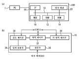
도 1의 (a)는 실시예 1에 따른 입력 장치의 블록도이다. (b)는 MCU의 기능 블록도이다.
도 2의 (a)는 터치 패널의 단면도이고, (b)는 터치 패널의 사시도이다.
도 3의 (a)는 도전막 간의 접촉 저항과 하중의 관계를 나타내는 도면이다. (b) 내지 (d)는 입력 조작을 도시하는 모식도이다.
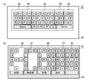
도 4의 (a) 내지 (c)는 키보드를 예시하는 평면도이다.
도 5의 (a) 및 (b)는 키보드를 예시하는 평면도이다.
도 6은 영역 설정의 처리를 예시하는 흐름도이다.
도 7은 입력 검출의 처리를 예시하는 흐름도이다.
도 8의 (a)는 터치 패널의 단면도이고, (b)는 터치 패널의 평면도이다.
도 9의 (a)는 정전 용량의 변화를 나타내는 도면이다. (b) 내지 (e)는 입력 조작을 도시하는 모식도이다.
도 10은 입력 검출의 처리를 예시하는 흐름도이다.1A is a block diagram of an input device according to the first embodiment. (b) is a functional block diagram of the MCU.
(A) is sectional drawing of a touch panel, (b) is a perspective view of a touch panel.
FIG. 3A is a diagram illustrating a relationship between contact resistance and load between conductive films. (b)-(d) is a schematic diagram which shows input operation.
4A to 4C are plan views illustrating keyboards.
5A and 5B are plan views illustrating keyboards.
6 is a flowchart illustrating a process of region setting.
7 is a flowchart illustrating a process of input detection.
(A) is sectional drawing of a touch panel, (b) is a top view of a touch panel.
9A is a diagram illustrating a change in capacitance. (b)-(e) is a schematic diagram which shows input operation.
10 is a flowchart illustrating a process of input detection.
이하, 도면을 참조하면서 본 발명의 실시 형태를 설명한다.EMBODIMENT OF THE INVENTION Hereinafter, embodiment of this invention is described, referring drawings.
실시예 1Example 1
도 1의 (a)는, 실시예 1에 따른 입력 장치(100)의 블록도이다. 도 1의 (a)에 도시하는 입력 장치(100)는, 서로 버스(18)로 접속된 MCU(Micro Control Unit)(10), RAM(Random Access Memory)(12), ROM(Read Only Memory)(14), IF(Interface)(16) 및 터치 패널(20)을 갖는다. 입력 장치(100)는, 예를 들어 스마트폰 또는 태블릿 단말기 등의 전자 기기이며, 퍼스널 컴퓨터(PC: Personal Computer)(1)에 접속할 수 있다. 터치 패널(20) 및 후술하는 터치 패널(70)은 입력부로서 기능한다.FIG. 1A is a block diagram of the
MCU(10)는, 입력 장치(100)를 제어하는 연산 장치이다. RAM(12)는 워킹 에어리어로서 기능한다. ROM(14)은 오퍼레이팅 시스템(OS), 애플리케이션 및 터치 패널 드라이버 등을 저장하고, 또한 후술하는 영역의 데이터 등을 저장하고 있다. IF(16)는 통신 인터페이스이며, IF(16)를 통하여 입력 장치(100)와 PC(1)의 통신이 행해진다.The
도 1의 (b)는, MCU(10)의 기능 블록도이다. 도 1의 (b)에 도시한 바와 같이, MCU(10)는 키 영역 제어부(30), 영역 제어부(32), 감도 제어부(34), 검출부(36) 및 입력 검출부(38)로서 기능한다. 키 영역 제어부(30)는, 터치 패널(20)에 표시되는 키보드의 키로 되는 영역의 설정 및 변경 등을 행한다. 영역 제어부(32)는, 표시되는 키보드 내에 적어도 하나의 영역을 정한다. 감도 제어부(34)는, 유저의 입력 조작에 대한 감도를 영역마다 설정한다. 검출부(36)는, 터치 패널(20)이 터치되었을 때의 접촉 저항 등 입력 조작의 강도를 취득한다. 입력 검출부(38)는 접촉 저항 및 감도에 따라 터치 패널(20)로의 입력을 검출한다.1B is a functional block diagram of the
도 2의 (a)는 터치 패널(20)의 단면도이고, 도 2의 (b)는 터치 패널(20)의 사시도이다. 터치 패널(20)은 저항막 방식의 터치 패널이며, 도 2의 (a)에 도시한 바와 같이 기판(41 및 43), 도전막(42 및 44), 접착층(45) 및 도트 스페이서(46)를 갖는다. 기판(41)의 하면에 도전막(42)이 부착되고, 기판(43)의 상면에 도전막(44)이 부착되어 있다. 도전막(42)과 도전막(44)은 이격되어, 사이에 복수의 도트 스페이서(46)가 마련되어 있다. 도전막(42)과 도전막(44)은, 주연부에 마련된 접착층(45)에 의하여 접착되어 있다.FIG. 2A is a cross-sectional view of the
기판(41 및 43)은 유리 또는 수지 등 투명한 재료로 형성되어 있다. 도전막(42 및 44)은, 예를 들어 산화인듐주석(ITO: Indium Tin Oxide)으로 형성된 투명한 도전막이다. 접착층(45) 및 도트 스페이서(46)는 절연체로 형성되어 있다.The
액정 디스플레이 등 표시부(40)가 기판(41 및 43)에 중첩되고, 유저는 터치 패널(20)을 통하여 표시부(40)의 화면을 시인할 수 있다. 터치 패널(20)에 키보드를 표시하여, 이하와 같은 방법으로 터치 패널(20)을 조작한 점의 X 좌표 및 Y 좌표를 검출함으로써, 유저에 의한 소프트웨어 키보드의 입력 조작을 접수하는 것이 가능하다.The
도 2의 (b)에 도시한 바와 같이, 도전막(42)의 X측의 2개의 변에는 전극(47)이 마련되어 있다. 도전막(44)의 Y측의 2개의 변에는 전극(48)이 마련되어 있다. 전극(47 및 48)은, 예를 들어 은(Ag) 등의 금속으로 형성되어 있다.As shown in FIG. 2B,
도전막(42)과 도전막(44)이 접촉한 점의 X 좌표를 검출하는 경우, 1쌍의 전극(47) 중 한쪽을 전원 Vcc에 접속하고 다른 쪽을 접지한다. 이것에 의하여 X 방향으로 전위 구배가 발생한다. 이때의 전위를 전극(48)에서 검출하여, 도시하지 않은 AD 컨버터 등을 통하여 MCU(10)에 입력한다. 접촉점의 Y 좌표를 검출하는 경우, 1쌍의 전극(48) 중 한쪽을 전원 Vcc에 접속하고 다른 쪽을 접지하고, 전극(47)에서 검출한 전위를 MCU(10)에 입력한다. 유저의 압박의 강도에 의하여 도전막 간의 접촉 저항이 변화되기 때문에, 전극에서 검출되는 전위도 압박의 강도에 따라 변화된다.When detecting the X coordinate of the point where the
도 3의 (a)는, 도전막(42)과 도전막(44) 간의 접촉 저항과 도전막(42)에 가해지는 하중의 관계를 나타내는 도면이다. 횡축은 도전막(42)에 가해지는 하중이고, 종축은 접촉 저항이다. 도 3의 (a)에 나타낸 바와 같이, 하중이 클수록 접촉 저항은 낮아진다. 달리 말하면, 유저가 터치 패널(20)을 약하게 압박하면 도전막끼리의 접촉 면적이 작기 때문에 접촉 저항은 높아지고, 강하게 압박하면 접촉 면적이 상대적으로 커지기 때문에 접촉 저항은 낮아진다. 도 3의 (a)에서는, 하중이 N1인 경우, 접촉 저항은 R1이다. Rth1 내지 Rth3은 역치이며, 후술하는 바와 같이 키보드 내의 영역마다 상이한 역치가 설정된다. 접촉 저항이, 각 키에 설정된 역치 이하로 되었을 때, 입력 검출부(38)는 그 영역 내에서의 키 입력을 검출한다. 또한 Rth1, R1, Rth2, R2, Rth3, R3의 순으로 접촉 저항은 작아진다.FIG. 3A is a diagram showing the relationship between the contact resistance between the
도 3의 (b) 내지 도 3의 (d)는, 입력 조작을 도시하는 모식도이며, 유저의 손가락(2), 도전막(42 및 44)을 도시하고 있다. 도 3의 (b) 내지 도 3의 (d)에 걸쳐 손가락(2)으로부터 가해지는 하중이 커지기 때문에, 도전막 간의 접촉 면적은 커져 접촉 저항은 낮아진다. 도 3의 (b)에서는, 손가락(2)으로부터 가해지는 하중이 도 3의 (a)의 N1이고 접촉 저항은 R1인 것으로 한다. 도 3의 (c)에서는, 하중이 N2이고 접촉 저항은 R2인 것으로 한다. 도 3의 (d)에서는, 하중이 N3이고 접촉 저항은 R3인 것으로 한다. 도 3의 (a) 내지 도 3의 (c) 중 어느 상태에 있는지는, 그때의 접촉 저항과 역치 Rth1 내지 Rth3을 비교함으로써 판별할 수 있다.3 (b) to 3 (d) are schematic diagrams illustrating the input operation, and illustrate the user's
도 4의 (a) 내지 도 5의 (b)는 키보드를 예시하는 평면도이다. 도 4의 (a)에 도시하는 키보드(50), 도 4의 (b)에 도시하는 키보드(51), 도 4의 (c)에 도시하는 키보드(52)는 각각 알파벳 입력용의 QWERTY 배열의 소프트웨어 키보드이며, 터치 패널(20)의 디스플레이에 표시된다. 키보드(50 내지 52)는, 알파벳 A 내지 Z의 키, 상하좌우 각각의 방향 키, Enter 키 및 스페이스 키 등 복수의 키를 포함한다. 도 4의 (c)는 키보드(50 및 51)보다도 소형이며, 예를 들어 어린이용이다.4A to 4B are plan views illustrating keyboards. The
또한 키의 배열은 QWERTY 배열에 한정되지 않는다. 도 5의 (a)의 키보드(60)는 ABC 배열을 가지며, 좌측부터 순서대로 알파벳의 키가 ABC순으로 배열된다. 도 5의 (b)의 키보드(62)는 50음 배열을 가지며, 히라가나의 키가 포함된다.Also, the array of keys is not limited to the QWERTY array. The
키마다 유저가 터치 패널(20)에 가하는 하중은 상이하다. 예를 들어 유저가 새끼손가락으로 압박하는 키가 배치되는 영역에서는, 하중이 작기 때문에 도 3의 (b)와 같이 접촉 면적도 작아져 접촉 저항은, 예를 들어 R1 정도로 된다. 유저가 집게손가락으로 압박하는 키가 배치되는 영역에서는, 하중이 크기 때문에 도 3의 (d)와 같이 접촉 면적도 커져 접촉 저항은, 예를 들어 R3 정도로 된다.The load that the user applies to the
그래서 실시예 1에서는, 키보드(50) 내에 복수의 영역을 설정하여, 손가락으로 터치 패널(20)을 누를 때의 하중에 따라 영역마다 입력 조작에 대한 감도를 상이하게 한다. 도 6은, 영역 설정의 처리를 예시하는 흐름도이다. 도 6의 처리는, 예를 들어 PC(1)과 입력 장치(100)를 접속하여 유저가 PC(1)로부터 설정 커맨드를 입력함으로써 실행할 수 있다.Therefore, in the first embodiment, a plurality of areas are set in the
도 6에 도시한 바와 같이, 키 영역 제어부(30)는 키보드에 키를 설정한다(S10). 이때는, 예를 들어 알파벳 A 내지 Z의 키, 방향 키, Enter 키, 스페이스 키 등의 영역이 설정된다. 영역 제어부(32)는 키보드 내에 복수의 영역을 설정한다(S12). 감도 제어부(34)는 영역마다 감도를 설정한다(S14). ROM(14)은 키보드에 설정되는 키, 영역 및 감도를 관련지어 기억한다(S16). 이상으로 처리는 종료된다.As shown in FIG. 6, the
예를 들어 키 영역 제어부(30)는, 도 4의 (a)에 도시한 바와 같이 QWERTY 배열의 키를 설정한다. 영역 제어부(32)는 영역(53 내지 55)을 설정한다. 도 4의 (a)에 있어서, 영역 간에는 점선으로 구획되어 있다. 영역(53)은 우하향의 사선으로 표시되며, 문자 Q, A 및 P의 키, Enter 키 등을 포함한다. 영역(54)은 우상향의 사선으로 표시되며, 문자 T, Y 등의 키, 방향 키 등을 포함한다. 영역(55)은 교차하는 사선으로 표시되며, 스페이스 키 등을 포함한다. 감도 제어부(34)는 영역(53 내지 55)마다 감도를 정한다. 이것에 의하여 키보드(50)에 감도가 상이한 영역(53 내지 55)이 설정된다.For example, the key
감도란, 도 3의 (a)에 나타내는 역치에 대응하며, 역치가 높을수록 감도는 높고 역치가 낮을수록 감도는 낮다. 감도 제어부(34)는 영역(53)의 감도를 높게 하고, 영역(54)의 감도를 영역(53)보다도 낮게 하고, 영역(55)의 감도를 영역(54)보다도 낮게 한다. 구체적으로 감도 제어부(34)는 영역(53)의 역치를 도 3의 (a)의 Rth1, 영역(54)의 역치를 Rth2, 영역(55)의 역치를 Rth3으로 정한다.The sensitivity corresponds to the threshold shown in Fig. 3A, and the higher the threshold, the higher the sensitivity, and the lower the threshold, the lower the sensitivity. The
도 4의 (b)의 키보드(51)에는, 키보드(50)와는 상이한 위치에 영역(53 내지 55)이 설정되며, 각각의 역치가 Rth1 내지 Rth3으로 설정되어 있다. 도 4의 (c)의 키보드(52)의 영역(53 내지 55)은, 키보드(50)의 각 영역과 동일한 키를 포함한다.In the
도 5의 (a)에 도시하는 키보드(60)에는 영역(63 내지 65)이 포함된다. 영역(63)은 키보드(60)의 단부측에 위치하고, 영역(65)은 중앙측에 위치하고, 영역(64)은 영역(63)과 영역(65) 사이에 위치한다. 도 5의 (b)에 도시하는 키보드(62)에는 영역(66 내지 68)이 포함된다. 키보드(62)의 단부로부터 중앙측에 걸쳐 영역(66, 67 및 68)이 배치된다. 영역(63 및 66)의 역치는 Rth1이고, 영역(64 및 67)의 역치는 Rth2이고, 영역(65 및 68)의 역치는 Rth3이다.The
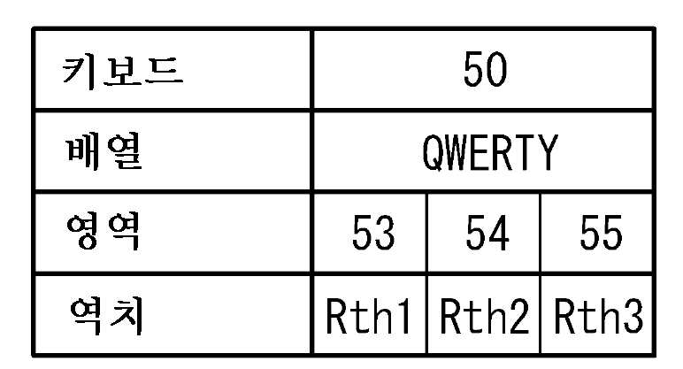
표 1 내지 표 5은, ROM(14)에 기억되는 데이터 테이블의 예이며, 각각 키보드(50 내지 52), 키보드(60 및 62)에 관한 키 배열, 설정된 영역, 및 영역마다의 역치를 나타내는 데이터를 포함한다.Tables 1 to 5 are examples of data tables stored in the


도 7은, 입력 검출의 처리를 예시하는 흐름도이다. MCU(10)는, ROM(14)으로부터 표시되는 키보드에 대응하는 데이터 테이블을 취득한다(S20). 검출부(36)는, 터치 패널(20)로의 입력 조작이 있었는지의 여부를 판정한다(S22). 부정 판정("아니오")이면 처리는 종료된다. 긍정 판정("예")이면 MCU(10)는 S24로 진행된다. 예를 들어 접촉 저항의 변화가 있으면, 검출부(36)는 입력 조작이 있었다고 판정한다.7 is a flowchart illustrating a process of input detection.
검출부(36)는, 터치 패널(20)의 입력 조작된 위치의 X 좌표 및 Y 좌표를 검출한다(S24). 입력 검출부(38)는 데이터 테이블을 참조하여, 입력 조작 위치가 포함되는 영역을 판별한다(S25). 다음으로, 입력 검출부(38)는, 입력 조작 시의 접촉 저항 R이 역치 Rth 이하인지의 여부를 판정한다(S26). 역치 Rth에는 영역에 따라 Rth1 내지 Rth3 중 어느 것이 대입된다.The
부정 판정의 경우, 입력 검출부(38)는 키의 입력이 없었다고 판정한다(S27). 한편, 긍정 판정의 경우, 입력 검출부(38)는 키의 입력이 있었다고 판정하고(S28), 조작된 키에 대응하는 문자나 정보가 입력된다. S27 또는 S28 후, 처리는 종료된다.In the case of a negative determination, the input detection unit 38 determines that there is no key input (S27). On the other hand, in the case of affirmation determination, the input detection part 38 determines that there was a key input (S28), and the character and information corresponding to the operated key are input. After S27 or S28, the process ends.
예를 들어 터치 패널(20)이, 도 4의 (a)에 도시하는 키보드(50)를 표시하고 있는 경우, MCU(10)는 ROM(14)으로부터 표 1의 데이터 테이블을 취득하여 영역(53 내지 55) 및 역치 Rth1 내지 Rth3을 판독한다. 유저가 키보드(50)의 문자 S를 터치하면, S24에서 S의 키에 대응하는 X 좌표 및 Y 좌표가 검출된다. S의 키는 영역(53)에 포함되기 때문에 입력 검출부(38)는 역치로서 Rth1을 선택한다. 입력 검출부(38)는, 키가 압박되었을 때의 접촉 저항 R이 역치 Rth1 이하인 경우, 문자 S의 입력을 검출한다.For example, when the
또한 유저가 스페이스 키를 터치하였을 때, 입력 검출부(38)는 역치로서 Rth3을 선택한다. 입력 검출부(38)는, 스페이스 키가 터치되었을 때의 접촉 저항이 Rth3보다 크면 키 입력을 검출하지 않는다. 한편, 도 3의 (d)와 같이, 손가락(2)이 터치 패널(20)에 강하게 접촉하여 접촉 저항이 Rth3 이하로 된 경우, 입력 검출부(38)는 입력을 검출한다.In addition, when the user touches the space key, the input detection unit 38 selects Rth3 as the threshold value. The input detector 38 does not detect key input when the contact resistance when the space key is touched is larger than Rth3. On the other hand, as shown in FIG. 3D, when the
실시예 1에 의하면, 감도 제어부(34)는 키보드(50)의 영역(53 내지 53)마다 역치를 상이하게 하고, 입력 검출부(38)는 접촉 저항과 각 영역에 설정된 역치에 기초하여 키의 입력을 검출한다. 예를 들어 영역(53)은 높은 역치를 갖고 감도가 높다. 이 때문에, 유저가 도 3의 (b)와 같이 터치 패널(20)에 가볍게 접촉하더라도 입력 검출부(38)는 입력을 검출한다. 한편, 영역(54)의 감도는 영역(53)에 비하여 낮기 때문에, 유저가 도 3의 (c)와 같이 강하게 접촉하였을 때 입력 검출부(38)는 입력을 검출한다. 영역(55)의 감도는 영역(54)보다도 더 낮다. 이 때문에, 유저가 도 3의 (d)와 같이 보다 강하게 접촉하였을 때 입력 검출부(38)는 입력을 검출한다. 이상과 같이, 감도가 상이한 영역을 설정함으로써 조작감이 향상된다.According to the first embodiment, the
도 4의 (a) 내지 도 5의 (b)에 도시한 바와 같이, 각 영역은 인접하는 2개 이상의 키를 포함하는 것이 바람직하다. 이것에 의하여, 복수의 인접하는 키에 동일한 감도가 설정되며, 유저는 그들 키를 같은 정도의 강도로 접촉함으로써 키 입력을 할 수 있어서 조작감이 향상된다. 또한 키마다 감도를 설정하는 경우에 비하여 데이터 테이블에 설정해야 할 데이터양이 감소하기 때문에, 점유하는 메모리 용량을 저감시킬 수 있다. 또한 설정 시의 유저의 부담도 경감된다.As shown in Figs. 4A to 5B, each region preferably includes two or more adjacent keys. As a result, the same sensitivity is set for a plurality of adjacent keys, and the user can input the keys by touching the keys with the same intensity, thereby improving the operation feeling. In addition, since the amount of data to be set in the data table is reduced as compared with the case where sensitivity is set for each key, the memory capacity occupied can be reduced. In addition, the burden on the user at the time of setting is also reduced.
키보드의 단부측에는 감도가 높은 영역을 마련하고, 중앙측에는 감도가 낮은 영역을 마련하는 것이 바람직하다. 유저는, 키보드의 중앙측의 키는 강하게 압박하고 단부측의 키는 약하게 압박하는 경우가 있다. 압박의 강도에 대응한 영역을 정함으로써 조작감이 보다 향상된다.It is preferable to provide an area with high sensitivity on the end side of the keyboard and an area with low sensitivity on the center side. The user may press the key on the center side of the keyboard strongly and the key on the end side weakly. The operation feeling is further improved by determining the area corresponding to the strength of the pressing.
영역 제어부(32)는, 터치 패널(20) 상에 있어서의 유저의 손가락의 배치에 기초하여 영역을 정해도 된다. 터치하는 손가락에 의하여 터치 패널(20)에 가해지는 하중이 상이하기 때문에, 각 영역에 설정하는 감도도 손가락에 따라 상이하게 한다. 이것에 의하여 조작감이 향상된다.The
예를 들어 도 4의 (a)에 도시하는 키보드(50)에서는, 유저의 새끼손가락에 가까운 Q나 P 등의 키는 약하게 압박될 것으로 생각된다. 그래서 영역 제어부(32)는 이들 키를 영역(53)으로 설정하고, 감도 제어부(34)는 영역(53)의 감도를 높게 한다. 한편, 집게손가락에 가까운 T의 키 및 엄지손가락에 가까운 스페이스 키 등은, 새끼손가락으로 조작되는 경우와 비교하여 강하게 압박될 것으로 생각된다. 그래서 영역 제어부(32)는 이들 키를 영역(55)으로 설정하고, 감도 제어부(34)는 영역(55)의 감도를 낮게 한다. 이것에 의하여 조작감이 향상된다.For example, in the
감도 제어부(34)는 영역의 감도를 적절히 변경해도 된다. 예를 들어 키보드(50)의 영역(53)에 대한 역치를 Rth1보다 높게 함으로써 영역(53)의 감도를 높일 수 있다. 또한 영역(55)의 역치를 Rth3보다 낮게 함으로써 영역(55)의 감도를 낮게 할 수도 있다. 유저가 사용하는 빈도가 높은 영역의 감도를 높이고, 빈도가 낮은 영역의 감도를 저하시킬 수도 있다. 이와 같이 유저가 영역마다의 감도를 임의로 변경할 수 있기 때문에 조작감이 향상된다.The
키 영역 제어부(30)가 키를 정함으로써, 도 4의 (a) 내지 도 5의 (b)에 도시하는 QWERTY 배열의 키보드(50 내지 52), ABC 배열의 키보드(60) 및 50음 배열의 키보드(62)를 터치 패널(20)에 표시시킬 수 있다. 또한 키보드(50)와 동일한 키 배열이고 또한 사이즈가 작은 키보드(52)를 구성할 수도 있다. 이것에 의하여, 유저가 입력하고자 하는 문자, 및 유저의 손 크기 등에 따라 키보드를 변경할 수 있어 조작감이 향상된다.The key
실시예 2Example 2
실시예 2는, 저항막 방식의 터치 패널(20) 대신 투영형 정전 용량 방식의 터치 패널(70)을 이용하는 예이다. 터치 패널 이외의 구성은 실시예 1과 동일하다. 도 8의 (a)는 터치 패널(70)의 단면도이고, 도 8의 (b)는 터치 패널(70)의 평면도이다. 도 8의 (a)에 도시한 바와 같이, 터치 패널(70)은 기판(71), 전극층(72) 및 보호층(73)을 갖는다. 기판(71) 상에 전극층(72)이 부착되고, 전극층(72) 상을 보호층(73)이 덮는다. 기판(71)은 유리 등으로 형성되고, 전극층(72)은 ITO 등으로 형성되고, 보호층(73)은 절연체로 형성되며, 각각 투명하다. 터치 패널(70)에는 실시예 1과 같이 키보드(50 내지 52, 60 및 62) 등이 표시된다.The second embodiment is an example of using the projected
도 8의 (b)에 도시한 바와 같이, 전극층(72)은 복수의 전극(74 및 76)의 패턴을 갖는다. 전극(74 및 76)의 평면 형상은, 예를 들어 마름모형이며, X축 방향 및 Y축 방향으로 배열되어 있다. 전극(74)은 X 좌표 검출용의 전극이고, 전극(76)은 Y 좌표 검출용의 전극이다. 터치 패널(70)의 가장 외측에 위치하는 전극(74 및 76)으로부터 배선이 연신되어 MCU(10)에 접속된다. 도면 중의 상하 방향에 있어서 인접하는 전극(74) 간은 배선에 의하여 전기적으로 접속되고, 좌우 방향에 있어서 인접하는 전극(76) 간은 배선에 의하여 전기적으로 접속되어 있다. 인접하는 전극(74)과 전극(76)은 전기적으로 접속되지 않으며 이격되어 있다.As shown in FIG. 8B, the
유저의 손가락이 터치 패널(20)의 표면에 접촉하면 전극(74 및 76)과 손가락 간에 용량이 발생한다. 이것에 의하여, 유저의 터치가 없는 경우에 비해 전극 간의 용량이 증가한다. 이러한 용량의 변화에 따라 입력 위치를 검출할 수 있다.When the user's finger contacts the surface of the
도 9의 (a)는, 정전 용량의 변화를 나타내는 도면이다. 횡축은 시간이고, 종축은 전극(74 및 76) 간의 정전 용량이다. 도 9의 (b) 내지 도 9의 (e)는, 입력 조작을 도시하는 모식도이며, 유저의 손가락(2)과 터치 패널(70)을 도시하고 있다. 도 9의 (b) 내지 도 9의 (d)에 걸쳐 손가락(2)과 터치 패널(70)의 접촉 면적이 커지고, 이에 따라 용량도 커진다. 도 9의 (b)에서는 손가락(2)과 터치 패널(70)의 접촉 면적이 작으며, 용량은 C1이다. 도 9의 (c)에서는 접촉 면적이 보다 크며, 용량은 C1보다도 큰 C2이다. 도 9의 (d)에서는 접촉 면적이 더욱 크며, 용량은 C2보다도 큰 C3이다.9A is a diagram illustrating a change in capacitance. The horizontal axis is time and the vertical axis is the capacitance between the
도 9의 (b) 내지 도 9의 (d)에서는, 손가락(2)이 터치 패널(70)에 접촉하고 있다. 한편, 도 9의 (e)에서는, 손가락(2)은 터치 패널(70)에 접촉하지 않고 거리 D까지 접근해 있다. 도 9의 (e)에 도시한 바와 같이, 유저가 터치 패널(70)에 접촉하지 않더라도 손가락(2)이 터치 패널(70)에 접근함으로써 용량은 변화되어 입력 조작을 검출할 수 있다. 도 9의 (e)에서는, 용량은 C1보다 작은 C4로 되는 것으로 한다.In FIGS. 9B to 9D, the
실시예 2에 있어서도 도 6에 도시한 처리가 행해져, 도 4의 (a) 내지 도 5의 (b)에 도시한 바와 같이 키보드에 감도가 상이한 영역이 형성된다. 감도란, 도 9의 (a)에 나타내는 정전 용량의 역치이다. 역치가 높을수록 감도가 낮고, 역치가 낮을수록 감도가 높다. 감도 제어부(34)는, 도 4의 (a)에 도시하는 키보드(50)의 영역(53)의 감도를 높게 하고, 영역(54)의 감도를 영역(53)보다도 낮게 하고, 영역(55)의 감도를 영역(54)보다도 낮게 한다. 구체적으로 감도 제어부(34)는 영역(53)의 역치를 Cth1, 영역(54)의 역치를 Cth2, 영역(55)의 역치를 Cth3으로 정한다. ROM(14)은 표 1 내지 표 5과 마찬가지로, 키보드의 배열 및 영역마다의 감도를 포함하는 데이터 테이블을 기억한다.Also in Example 2, the process shown in FIG. 6 is performed, and the area | region from which a sensitivity differs is formed in a keyboard as shown to FIG. 4 (a)-FIG. 5 (b). The sensitivity is a threshold value of the capacitance shown in FIG. 9A. The higher the threshold, the lower the sensitivity. The lower the threshold, the higher the sensitivity. The
도 10은, 입력 검출의 처리를 예시하는 흐름도이며, 도 7의 S26 대신 S26a의 처리를 행한다. S20 내지 S25까지는 도 7과 마찬가지이다. 입력 검출부(38)는, 입력 조작 시의 용량 C(입력값)이 역치 Cth 이상인지의 여부를 판정한다(S26a). 이 역치 Cth에는, 조작되고 있는 영역에 따라 Cth1 내지 Cth3 중 어느 것이 대입된다. 부정 판정의 경우, 입력 검출부(38)는 키 입력이 없었다고 판정한다(S27). 한편, 긍정 판정의 경우, 입력 검출부(38)는 키 입력이 있었다고 판정한다(S28). S27 또는 S28 후, 처리는 종료된다.FIG. 10 is a flowchart illustrating an input detection process, and the process of S26a is performed instead of S26 of FIG. 7. S20 to S25 are the same as in FIG. The input detection part 38 determines whether the capacitance C (input value) at the time of an input operation is more than the threshold value Cth (S26a). Any one of Cth1 to Cth3 is substituted into the threshold Cth according to the region being operated. In the case of a negative determination, the input detection unit 38 determines that there is no key input (S27). On the other hand, in the case of affirmation determination, the input detection part 38 determines that there was a key input (S28). After S27 or S28, the process ends.
실시예 2에 의하면, 실시예 1과 마찬가지로 조작감이 향상된다. 터치 패널(70)은 정전 용량 방식이기 때문에 감도 제어부(34)는 감도로서 용량의 역치를 정한다. 역치를 높게 함으로써 그 영역의 감도를 저하시키고, 역치를 낮게 함으로써 그 영역의 감도를 높일 수 있다. 특히 도 9의 (e)와 같이, 유저가 터치 패널(70)에 접촉하지 않더라도 거리 D까지 근접함으로써 용량은 C4로 된다. 역치 Cth1을 C4보다도 작게 함으로써, 유저가 터치하지 않더라도 입력을 검출할 수 있다. 이것에 의하여 조작감이 더욱 향상된다.According to the second embodiment, the operation feeling is improved in the same manner as in the first embodiment. Since the
실시예 2에 있어서도 실시예 1과 마찬가지로, 키보드의 단부와 중앙부에서 감도를 변화시켜도 되고, 유저의 손가락에 따라 감도를 변화시켜도 된다. 특히 감도를 높이고자 하는 영역에 대해서는, 역치를, 도 9의 (a)에 있어서 가장 작은 역치인 Cth1로 하는 것이 바람직하다. 이와 같은 영역에서는, 터치 패널(70)에 손가락을 근접시키기만 하면 키 입력이 가능해진다. 반대로 손가락이 터치 패널(70)에 접촉하지 않는 한 키 입력을 하지 못하도록 하기 위해서는, 그 영역에 대한 역치를 높게 하면 된다.Also in Example 2, sensitivity may be changed in the edge part and center part of a keyboard similarly to Example 1, and a sensitivity may be changed according to a user's finger. It is preferable to set the threshold value to Cth1 which is the smallest threshold value in FIG.9 (a) about especially the area | region to which sensitivity is to be raised. In such an area, key input is possible only by bringing a finger close to the
실시예 1 및 2에 있어서는, 키보드에 감도가 상이한 3개의 영역을 형성하였지만, 예를 들어 2개의 영역을 형성해도 되고, 4개 이상의 영역을 형성해도 된다. 또한 키보드의 문자 등의 키는 터치 패널의 디스플레이에 화상으로서 표시되어도 되며, 예를 들어 터치 패널의 표면에 부착하는 시트에 인쇄된 것이어도 된다. 저항막 방식 및 정전 용량 방식 이외의 터치 패널을 이용해도 된다. 유저는 손가락 등 신체로 터치 패널에 접촉해도 되고, 펜 등을 이용하여 입력해도 된다. 유저는 PC(1)로부터 입력 장치(100)의 감도 등의 설정을 행해도 되고, 입력 장치(100)를 조작함으로써 입력 장치(100)의 감도 등의 설정을 행해도 된다.In Examples 1 and 2, although three areas with different sensitivity are formed in a keyboard, two areas may be formed, for example, and four or more areas may be formed. In addition, keys, such as a character of a keyboard, may be displayed as an image on the display of a touch panel, for example, may be printed on the sheet | seat which affixes on the surface of a touch panel. You may use touch panels other than a resistive film type and a capacitive type. The user may contact the touch panel with a finger or the like, or input using a pen or the like. The user may set the sensitivity of the
또한 본 발명은 상술한 실시 형태에 한정되는 것은 아니며, 그 요지를 일탈하지 않는 범위 내에서 다양하게 변형하여 실시하는 것이 가능하다.In addition, this invention is not limited to embodiment mentioned above, It can be variously modified and implemented in the range which does not deviate from the summary.
1: PC
10: MCU
12: RAM
14: ROM
16: IF
20: 터치 패널
30: 키 영역 제어부
32: 영역 제어부
34: 감도 제어부
36: 검출부
38: 입력 검출부
41, 43, 71: 기판
42, 44: 도전막
47, 48, 74, 76: 전극
50 내지 52, 60, 62: 키보드
53 내지 55, 63 내지 65, 66 내지 68: 영역
72: 전극층
100: 입력 장치1: PC
10: MCU
12: RAM
14: ROM
16: IF
20: touch panel
30: key area control
32: area control unit
34: sensitivity control unit
36: detector
38: input detector
41, 43, 71: substrate
42, 44: conductive film
47, 48, 74, 76: electrode
50 to 52, 60, 62: keyboard
53 to 55, 63 to 65, 66 to 68: region
72: electrode layer
100: input device
Claims (4)
상기 키에 대한 입력 조작의 감도를 정하는 감도 제어부와,
상기 입력 조작 및 상기 감도에 기초하여 상기 키로의 입력의 유무를 검출하는 입력 검출부와,
적어도 하나의 키를 포함하는 하나 또는 복수의 입력 영역을 상기 입력부에 정하는 영역 제어부를 구비하고,
상기 감도 제어부는 복수의 상기 입력 영역마다 상기 감도를 설정하는 것을 특징으로 하는 입력 장치.An input unit including a plurality of keys,
A sensitivity control unit for determining the sensitivity of the input operation to the key;
An input detector for detecting the presence or absence of an input to the key based on the input operation and the sensitivity;
An area control unit for defining one or a plurality of input areas including at least one key to the input unit,
And the sensitivity control unit sets the sensitivity for each of the plurality of input areas.
상기 입력 영역은 2개 이상의 서로 인접하는 키를 포함하는, 입력 장치.The method of claim 1,
And the input area comprises two or more adjacent keys.
상기 영역 제어부는, 상기 입력부 상에 있어서의 유저의 손가락의 배치에 기초하여 상기 복수의 입력 영역을 정하는, 입력 장치.The method according to claim 1 or 2,
The area controller determines the plurality of input areas based on the arrangement of the user's fingers on the input unit.
상기 키에 대한 입력 조작의 감도를 정하는 감도 제어부와,
상기 입력 조작에 의한 입력값이 역치 이상인 경우, 상기 키로의 입력을 검출하는 입력 검출부를 구비하고,
상기 복수의 키는 제1 키 및 제2 키를 포함하고,
상기 감도 제어부는, 상기 제1 키에 대응하는 역치를, 상기 제2 키에 대응하는 역치보다도 작게 하고, 또한 유저가 상기 제1 키에 소정 거리까지 접근하였을 때의 입력값보다 작게 하는 것을 특징으로 하는 입력 장치.A capacitive touch panel including a plurality of keys,
A sensitivity control unit for determining the sensitivity of the input operation to the key;
An input detector for detecting an input to the key when the input value by the input operation is equal to or greater than a threshold value,
The plurality of keys comprises a first key and a second key,
The sensitivity control unit makes the threshold value corresponding to the first key smaller than the threshold value corresponding to the second key and smaller than the input value when the user approaches the first key to a predetermined distance. Input device.
Applications Claiming Priority (2)
| Application Number | Priority Date | Filing Date | Title |
|---|---|---|---|
| JP2018156897A JP2020030712A (en) | 2018-08-24 | 2018-08-24 | Input device |
| JPJP-P-2018-156897 | 2018-08-24 |
Publications (1)
| Publication Number | Publication Date |
|---|---|
| KR20200023183A true KR20200023183A (en) | 2020-03-04 |
Family
ID=69586875
Family Applications (1)
| Application Number | Title | Priority Date | Filing Date |
|---|---|---|---|
| KR1020190088750A KR20200023183A (en) | 2018-08-24 | 2019-07-23 | Input device |
Country Status (4)
| Country | Link |
|---|---|
| US (1) | US20200064961A1 (en) |
| JP (1) | JP2020030712A (en) |
| KR (1) | KR20200023183A (en) |
| CN (1) | CN110858112A (en) |
Families Citing this family (1)
| Publication number | Priority date | Publication date | Assignee | Title |
|---|---|---|---|---|
| US11740706B2 (en) * | 2020-05-11 | 2023-08-29 | Darfon Electronics Corp. | Keyboard touch electrode module and touch keyboard therewith |
Citations (2)
| Publication number | Priority date | Publication date | Assignee | Title |
|---|---|---|---|---|
| JP2012098828A (en) | 2010-10-29 | 2012-05-24 | Minebea Co Ltd | Input device and input control method for electronic device |
| JP2016162364A (en) | 2015-03-04 | 2016-09-05 | ソニー株式会社 | Input device and information processor |
Family Cites Families (5)
| Publication number | Priority date | Publication date | Assignee | Title |
|---|---|---|---|---|
| US6684166B2 (en) * | 2002-05-02 | 2004-01-27 | International Business Machines Corporation | Pressure sensitive keyboard |
| JP5561089B2 (en) * | 2010-10-15 | 2014-07-30 | ソニー株式会社 | Information processing apparatus, information processing method, and computer program |
| JP6006487B2 (en) * | 2011-12-19 | 2016-10-12 | ミネベア株式会社 | Input device |
| US9460029B2 (en) * | 2012-03-02 | 2016-10-04 | Microsoft Technology Licensing, Llc | Pressure sensitive keys |
| US10120506B2 (en) * | 2013-11-12 | 2018-11-06 | Microsoft Technology Licensing, Llc | Multi-touch capacitive sensing surface |
-
2018
- 2018-08-24 JP JP2018156897A patent/JP2020030712A/en active Pending
-
2019
- 2019-06-24 US US16/449,834 patent/US20200064961A1/en not_active Abandoned
- 2019-07-23 KR KR1020190088750A patent/KR20200023183A/en not_active Application Discontinuation
- 2019-08-08 CN CN201910727709.4A patent/CN110858112A/en active Pending
Patent Citations (2)
| Publication number | Priority date | Publication date | Assignee | Title |
|---|---|---|---|---|
| JP2012098828A (en) | 2010-10-29 | 2012-05-24 | Minebea Co Ltd | Input device and input control method for electronic device |
| JP2016162364A (en) | 2015-03-04 | 2016-09-05 | ソニー株式会社 | Input device and information processor |
Also Published As
| Publication number | Publication date |
|---|---|
| US20200064961A1 (en) | 2020-02-27 |
| JP2020030712A (en) | 2020-02-27 |
| CN110858112A (en) | 2020-03-03 |
Similar Documents
| Publication | Publication Date | Title |
|---|---|---|
| US7423635B2 (en) | Single-layer touchpad having touch zones | |
| US9575568B2 (en) | Multi-function keys providing additional functions and previews of functions | |
| US20100253630A1 (en) | Input device and an input processing method using the same | |
| KR101149980B1 (en) | Touch sensor for a display screen of an electronic device | |
| KR20130073824A (en) | Touch keypad module and mode switching method thereof | |
| JP2001222378A (en) | Touch panel input device | |
| US10289210B1 (en) | Enabling touch on a tactile keyboard | |
| US10558298B2 (en) | Touch control substrate, driving method thereof, display panel and display device | |
| JP2008225980A (en) | Composite touch sensor | |
| JP3132106U (en) | Combined touch sensor | |
| US9696576B2 (en) | Pen writing on one-dimensional capacitive touch sensor | |
| JP2011022958A (en) | Input device | |
| KR20200023183A (en) | Input device | |
| KR101585934B1 (en) | Capacitive type touch panel | |
| US20090135156A1 (en) | Touch sensor for a display screen of an electronic device | |
| JPH1027053A (en) | Keyboard device | |
| JP5759658B2 (en) | Input system and method of operating electronic device | |
| JP2015172799A (en) | touch operation input device | |
| KR101494259B1 (en) | Composite touch pannel with appendix and method for detecting touch using therefor | |
| US20230176681A1 (en) | Hovering touch panel and hovering touch device | |
| KR20170114298A (en) | Touch keyboard having touch sensor and touch location, keystroke verification method using touch keyboard | |
| CN110262703B (en) | Hybrid touch module | |
| KR200208104Y1 (en) | Data input device using touch pad | |
| KR20220157707A (en) | Touch screen integreated multiple sensor functions | |
| KR101230115B1 (en) | Apparatus for input keypad of capacitive overlay |
Legal Events
| Date | Code | Title | Description |
|---|---|---|---|
| A201 | Request for examination | ||
| E902 | Notification of reason for refusal | ||
| E90F | Notification of reason for final refusal | ||
| E601 | Decision to refuse application |