KR20200022505A - Wire to board terminal - Google Patents
Wire to board terminal Download PDFInfo
- Publication number
- KR20200022505A KR20200022505A KR1020207003944A KR20207003944A KR20200022505A KR 20200022505 A KR20200022505 A KR 20200022505A KR 1020207003944 A KR1020207003944 A KR 1020207003944A KR 20207003944 A KR20207003944 A KR 20207003944A KR 20200022505 A KR20200022505 A KR 20200022505A
- Authority
- KR
- South Korea
- Prior art keywords
- base
- leg
- crimp
- circuit board
- wire
- Prior art date
Links
Images


Classifications
-
- H—ELECTRICITY
- H01—ELECTRIC ELEMENTS
- H01R—ELECTRICALLY-CONDUCTIVE CONNECTIONS; STRUCTURAL ASSOCIATIONS OF A PLURALITY OF MUTUALLY-INSULATED ELECTRICAL CONNECTING ELEMENTS; COUPLING DEVICES; CURRENT COLLECTORS
- H01R12/00—Structural associations of a plurality of mutually-insulated electrical connecting elements, specially adapted for printed circuits, e.g. printed circuit boards [PCB], flat or ribbon cables, or like generally planar structures, e.g. terminal strips, terminal blocks; Coupling devices specially adapted for printed circuits, flat or ribbon cables, or like generally planar structures; Terminals specially adapted for contact with, or insertion into, printed circuits, flat or ribbon cables, or like generally planar structures
- H01R12/70—Coupling devices
- H01R12/71—Coupling devices for rigid printing circuits or like structures
- H01R12/75—Coupling devices for rigid printing circuits or like structures connecting to cables except for flat or ribbon cables
-
- H—ELECTRICITY
- H01—ELECTRIC ELEMENTS
- H01R—ELECTRICALLY-CONDUCTIVE CONNECTIONS; STRUCTURAL ASSOCIATIONS OF A PLURALITY OF MUTUALLY-INSULATED ELECTRICAL CONNECTING ELEMENTS; COUPLING DEVICES; CURRENT COLLECTORS
- H01R4/00—Electrically-conductive connections between two or more conductive members in direct contact, i.e. touching one another; Means for effecting or maintaining such contact; Electrically-conductive connections having two or more spaced connecting locations for conductors and using contact members penetrating insulation
- H01R4/10—Electrically-conductive connections between two or more conductive members in direct contact, i.e. touching one another; Means for effecting or maintaining such contact; Electrically-conductive connections having two or more spaced connecting locations for conductors and using contact members penetrating insulation effected solely by twisting, wrapping, bending, crimping, or other permanent deformation
- H01R4/18—Electrically-conductive connections between two or more conductive members in direct contact, i.e. touching one another; Means for effecting or maintaining such contact; Electrically-conductive connections having two or more spaced connecting locations for conductors and using contact members penetrating insulation effected solely by twisting, wrapping, bending, crimping, or other permanent deformation by crimping
- H01R4/183—Electrically-conductive connections between two or more conductive members in direct contact, i.e. touching one another; Means for effecting or maintaining such contact; Electrically-conductive connections having two or more spaced connecting locations for conductors and using contact members penetrating insulation effected solely by twisting, wrapping, bending, crimping, or other permanent deformation by crimping for cylindrical elongated bodies, e.g. cables having circular cross-section
- H01R4/184—Electrically-conductive connections between two or more conductive members in direct contact, i.e. touching one another; Means for effecting or maintaining such contact; Electrically-conductive connections having two or more spaced connecting locations for conductors and using contact members penetrating insulation effected solely by twisting, wrapping, bending, crimping, or other permanent deformation by crimping for cylindrical elongated bodies, e.g. cables having circular cross-section comprising a U-shaped wire-receiving portion
- H01R4/185—Electrically-conductive connections between two or more conductive members in direct contact, i.e. touching one another; Means for effecting or maintaining such contact; Electrically-conductive connections having two or more spaced connecting locations for conductors and using contact members penetrating insulation effected solely by twisting, wrapping, bending, crimping, or other permanent deformation by crimping for cylindrical elongated bodies, e.g. cables having circular cross-section comprising a U-shaped wire-receiving portion combined with a U-shaped insulation-receiving portion
-
- H—ELECTRICITY
- H01—ELECTRIC ELEMENTS
- H01R—ELECTRICALLY-CONDUCTIVE CONNECTIONS; STRUCTURAL ASSOCIATIONS OF A PLURALITY OF MUTUALLY-INSULATED ELECTRICAL CONNECTING ELEMENTS; COUPLING DEVICES; CURRENT COLLECTORS
- H01R12/00—Structural associations of a plurality of mutually-insulated electrical connecting elements, specially adapted for printed circuits, e.g. printed circuit boards [PCB], flat or ribbon cables, or like generally planar structures, e.g. terminal strips, terminal blocks; Coupling devices specially adapted for printed circuits, flat or ribbon cables, or like generally planar structures; Terminals specially adapted for contact with, or insertion into, printed circuits, flat or ribbon cables, or like generally planar structures
- H01R12/50—Fixed connections
- H01R12/51—Fixed connections for rigid printed circuits or like structures
- H01R12/53—Fixed connections for rigid printed circuits or like structures connecting to cables except for flat or ribbon cables
-
- H—ELECTRICITY
- H01—ELECTRIC ELEMENTS
- H01R—ELECTRICALLY-CONDUCTIVE CONNECTIONS; STRUCTURAL ASSOCIATIONS OF A PLURALITY OF MUTUALLY-INSULATED ELECTRICAL CONNECTING ELEMENTS; COUPLING DEVICES; CURRENT COLLECTORS
- H01R12/00—Structural associations of a plurality of mutually-insulated electrical connecting elements, specially adapted for printed circuits, e.g. printed circuit boards [PCB], flat or ribbon cables, or like generally planar structures, e.g. terminal strips, terminal blocks; Coupling devices specially adapted for printed circuits, flat or ribbon cables, or like generally planar structures; Terminals specially adapted for contact with, or insertion into, printed circuits, flat or ribbon cables, or like generally planar structures
- H01R12/50—Fixed connections
- H01R12/51—Fixed connections for rigid printed circuits or like structures
- H01R12/55—Fixed connections for rigid printed circuits or like structures characterised by the terminals
- H01R12/58—Fixed connections for rigid printed circuits or like structures characterised by the terminals terminals for insertion into holes
-
- H—ELECTRICITY
- H01—ELECTRIC ELEMENTS
- H01R—ELECTRICALLY-CONDUCTIVE CONNECTIONS; STRUCTURAL ASSOCIATIONS OF A PLURALITY OF MUTUALLY-INSULATED ELECTRICAL CONNECTING ELEMENTS; COUPLING DEVICES; CURRENT COLLECTORS
- H01R12/00—Structural associations of a plurality of mutually-insulated electrical connecting elements, specially adapted for printed circuits, e.g. printed circuit boards [PCB], flat or ribbon cables, or like generally planar structures, e.g. terminal strips, terminal blocks; Coupling devices specially adapted for printed circuits, flat or ribbon cables, or like generally planar structures; Terminals specially adapted for contact with, or insertion into, printed circuits, flat or ribbon cables, or like generally planar structures
- H01R12/70—Coupling devices
- H01R12/7082—Coupling device supported only by cooperation with PCB
-
- H—ELECTRICITY
- H01—ELECTRIC ELEMENTS
- H01R—ELECTRICALLY-CONDUCTIVE CONNECTIONS; STRUCTURAL ASSOCIATIONS OF A PLURALITY OF MUTUALLY-INSULATED ELECTRICAL CONNECTING ELEMENTS; COUPLING DEVICES; CURRENT COLLECTORS
- H01R4/00—Electrically-conductive connections between two or more conductive members in direct contact, i.e. touching one another; Means for effecting or maintaining such contact; Electrically-conductive connections having two or more spaced connecting locations for conductors and using contact members penetrating insulation
- H01R4/02—Soldered or welded connections
- H01R4/023—Soldered or welded connections between cables or wires and terminals
-
- H—ELECTRICITY
- H01—ELECTRIC ELEMENTS
- H01R—ELECTRICALLY-CONDUCTIVE CONNECTIONS; STRUCTURAL ASSOCIATIONS OF A PLURALITY OF MUTUALLY-INSULATED ELECTRICAL CONNECTING ELEMENTS; COUPLING DEVICES; CURRENT COLLECTORS
- H01R4/00—Electrically-conductive connections between two or more conductive members in direct contact, i.e. touching one another; Means for effecting or maintaining such contact; Electrically-conductive connections having two or more spaced connecting locations for conductors and using contact members penetrating insulation
- H01R4/10—Electrically-conductive connections between two or more conductive members in direct contact, i.e. touching one another; Means for effecting or maintaining such contact; Electrically-conductive connections having two or more spaced connecting locations for conductors and using contact members penetrating insulation effected solely by twisting, wrapping, bending, crimping, or other permanent deformation
- H01R4/18—Electrically-conductive connections between two or more conductive members in direct contact, i.e. touching one another; Means for effecting or maintaining such contact; Electrically-conductive connections having two or more spaced connecting locations for conductors and using contact members penetrating insulation effected solely by twisting, wrapping, bending, crimping, or other permanent deformation by crimping
-
- H—ELECTRICITY
- H01—ELECTRIC ELEMENTS
- H01R—ELECTRICALLY-CONDUCTIVE CONNECTIONS; STRUCTURAL ASSOCIATIONS OF A PLURALITY OF MUTUALLY-INSULATED ELECTRICAL CONNECTING ELEMENTS; COUPLING DEVICES; CURRENT COLLECTORS
- H01R4/00—Electrically-conductive connections between two or more conductive members in direct contact, i.e. touching one another; Means for effecting or maintaining such contact; Electrically-conductive connections having two or more spaced connecting locations for conductors and using contact members penetrating insulation
- H01R4/24—Connections using contact members penetrating or cutting insulation or cable strands
- H01R4/2495—Insulation penetration combined with permanent deformation of the contact member, e.g. crimping
-
- H—ELECTRICITY
- H01—ELECTRIC ELEMENTS
- H01R—ELECTRICALLY-CONDUCTIVE CONNECTIONS; STRUCTURAL ASSOCIATIONS OF A PLURALITY OF MUTUALLY-INSULATED ELECTRICAL CONNECTING ELEMENTS; COUPLING DEVICES; CURRENT COLLECTORS
- H01R12/00—Structural associations of a plurality of mutually-insulated electrical connecting elements, specially adapted for printed circuits, e.g. printed circuit boards [PCB], flat or ribbon cables, or like generally planar structures, e.g. terminal strips, terminal blocks; Coupling devices specially adapted for printed circuits, flat or ribbon cables, or like generally planar structures; Terminals specially adapted for contact with, or insertion into, printed circuits, flat or ribbon cables, or like generally planar structures
- H01R12/50—Fixed connections
- H01R12/51—Fixed connections for rigid printed circuits or like structures
- H01R12/55—Fixed connections for rigid printed circuits or like structures characterised by the terminals
- H01R12/58—Fixed connections for rigid printed circuits or like structures characterised by the terminals terminals for insertion into holes
- H01R12/585—Terminals having a press fit or a compliant portion and a shank passing through a hole in the printed circuit board
Landscapes
- Coupling Device And Connection With Printed Circuit (AREA)
- Multi-Conductor Connections (AREA)
Abstract
단자는 2개의 크림프 섹션을 포함하고, 하나는 나선 도체와 맞물리고 하나는 절연된 도체와 맞물린다. 단자는, 지지 회로 기판의 개구에 위치되도록 구성되는 2개의 다리를 포함한다. 따라서, 와이어는 낮은 프로파일(low profile) 방식으로 회로 기판에 전기적으로 연결될 수 있다.The terminal includes two crimp sections, one with a spiral conductor and one with an insulated conductor. The terminal includes two legs configured to be positioned in the opening of the support circuit board. Thus, the wire can be electrically connected to the circuit board in a low profile manner.
Description
관련 출원Related Applications
본 출원은 2012년 11월 27일자로 출원된 미국 가출원 제61/730,385호 및 2013년 5월 21일자로 출원된 미국 가출원 제61/825,666호에 대한 우선권을 주장하며, 이들 출원은 그 전체가 참조에 의해 본원에 통합된다. This application claims priority to US Provisional Application No. 61 / 730,385, filed November 27, 2012 and US Provisional Application No. 61 / 825,666, filed May 21, 2013, which are incorporated by reference in their entirety. Incorporated herein by.
발명의 분야Field of invention
본 발명은 단자의 분야에 관한 것으로, 특히 회로 기판 상에 탑재될 수 있는 단자의 분야에 관한 것이다.The present invention relates to the field of terminals, and more particularly to the field of terminals which can be mounted on a circuit board.
단자는 회로 기판에 대한 연결을 위해 제공되어 왔다. 디자인은 기판에 제공되는 비아(via) 안으로 압입(press-fit)되거나 솔더링되도록 구성될 수 있다. 강건성이 더 큰 가치를 갖는 용례의 경우, 디자인은 회로 기판에 솔더링될 수 있는 단자 디자인에 더 초점이 맞춰지는 경향이 있다. 2개의 기본적인 디자인이 가능한데, 하나는 하우징을 구비하는 것이고, 하나는 하우징을 구비하지 않는 것이다. 하우징은 다수의 이점을 제공하지만 더 비용이 많이 드는 경향이 있다. 결과적으로, 소정의 용례는 단자 전용 디자인이 더 알맞을 수도 있다.Terminals have been provided for connection to circuit boards. The design can be configured to be press-fit or soldered into vias provided in the substrate. For applications where the robustness is of greater value, the design tends to be more focused on terminal designs that can be soldered to the circuit board. Two basic designs are possible, one with housing and one without housing. Housings offer a number of advantages but tend to be more expensive. As a result, certain applications may be more suitable for terminal designs.
그러나, 기존 디자인은 낮은 프로파일(low profile)을 제공하지 못하는 경향이 있다. 따라서, 특정인들은 단자 디자인과 와이어-기판간 커넥터에 대한 추가적인 향상을 원할 수 있을 것이다.However, existing designs tend not to provide a low profile. Thus, certain people may wish to make further improvements to the terminal design and the wire-to-board connector.
도체를 둘러싸는 절연층으로 구성되는 와이어에 고정될 수 있는 단자가 개시되며 그 단자는 제1의 크림프부(crimp portion)와 제2의 크림프부를 포함한다. 제1의 크림프부는 절연층 및 도체와 맞물리도록 구성된다. 제2의 크림프부는 절연층이 제거된 도체와 맞물리도록 구성된다. 제1 및 제2의 크림프 각각은, 단자가 와이어에 고정될 때, 날개가 와이어의 대응하는 영역을 단단히 꼭 잡도록, 서로를 향해 접히는 한 쌍의 날개를 포함할 수 있다. 2개의 다리는, 개개의 다리가 단자의 대향측에 위치된 상태로 또는 두 다리가 단자의 동일 측에 위치된 상태로, 제1 및 제2의 크림프부 사이에 위치된다. 다리는 회로 기판에 솔더링되도록 구성되고 또한 바늘귀 구조로 구성될 수 있는 미부(tail) 또는 회로 기판에 대한 솔더링에 바람직한 임의의 다른 종래의 미부를 포함한다. 따라서, 와이어는 낮은 프로파일 방식으로 회로 기판에 전기적으로 연결될 수 있다.A terminal is disclosed that can be secured to a wire comprised of an insulating layer surrounding a conductor, the terminal comprising a first crimp portion and a second crimp portion. The first crimp portion is configured to engage the insulating layer and the conductor. The second crimp portion is configured to engage the conductor with the insulating layer removed. Each of the first and second crimps may include a pair of vanes that fold towards each other such that when the terminals are secured to the wire, the vanes firmly grip the corresponding area of the wire. The two legs are located between the first and second crimp portions, with the individual legs positioned on opposite sides of the terminals or with both legs positioned on the same side of the terminals. The legs include a tail or any other conventional tail that is desirable for soldering to the circuit board, which may be configured for soldering to the circuit board and may also be of a needle-eye structure. Thus, the wire can be electrically connected to the circuit board in a low profile manner.
본 발명에 따른 단자는 양측에 제1 단부 및 제2 단부를 갖는 베이스, 상기 제1 단부에 근접하고 상기 베이스로부터 외측으로 연장된 제1 크림프부로서, 와이어의 노출된 도체에 맞물리도록 구성된 제1 크림프부; 상기 제2 단부에 근접하고 상기 베이스로부터 외측으로 연장된 제2 크림프부로서, 와이어의 절연층에 맞물리도록 구성된 제2 크림프부; 및 상기 베이스로부터 외측으로 연장된 제1의 다리 및 제2의 다리를 포함하고, 상기 제1의 다리는 회로 기판의 대응되는 제1 개구 안으로 연장되도록 구성되고, 상기 제2의 다리는 상기 회로 기판의 대응되는 제2 개구 안으로 연장되도록 구성될 수 있다. 상기 단자는 상기 제1의 다리 및 제2의 다리 각각은 미부를 포함하고, 상기 제1의 다리 및 제2의 다리 각각의 미부는 바늘귀 구조를 갖고, 상기 미부는 상기 회로 기판의 대응되는 개구 안으로 압입(press-fit)되도록 구성될 수 있다. 상기 제1 크림프부는 상기 와이어의 노출된 도체의 양측의 주위로 연장되어 접히도록 구성된 제1 날개 및 제2 날개로 형성될 수 있다. 상기 제2 크림프부는 상기 와이어의 절연층의 양측의 주위로 연장되어 접히도록 구성된 제1 날개 및 제2 날개로 형성될 수 있다. 상기 제1의 다리 및 제2의 다리는 제1 크림프부 및 제2 크림프부 사이에서 상기 베이스로부터 외측으로 연장되고, 상기 제1 크림프부 및 제2 크림프부는 상기 베이스로부터 외측으로 연장될 수 있다. 상기 베이스는 마주하는 제1 및 제2 측부를 갖고, 상기 제1의 다리는 상기 베이스의 제1 측부로부터 외측으로 연장되고, 상기 제2의 다리는 상기 베이스의 제2 측부로부터 외측으로 연장되고, 상기 제1 및 제2 크림프부와 제1의 다리 및 제2의 다리는 각각 대체로 수직으로 상기 베이스로부터 외측으로 연장될 수 있다. 상기 베이스는 측부를 갖고, 상기 제1의 다리 및 제2의 다리 각각은 상기 베이스의 측부로부터 외측으로 연장되 고, 상기 제1 및 제2 크림프부 각각은 대체로 수직으로 상기 베이스로부터 외측으로 연장되고, 상기 제1의 다리 및 제2의 다리 각각은 대체로 수직으로 상기 베이스로부터 외측으로 연장될 수 있다. A terminal according to the invention is a base having a first end and a second end on both sides, a first crimp portion proximate to the first end and extending outward from the base, the first configured to engage an exposed conductor of the wire. Crimp part; A second crimp portion proximate said second end and extending outwardly from said base, said second crimp portion configured to engage an insulating layer of wire; And a first leg and a second leg extending outwardly from the base, the first leg configured to extend into a corresponding first opening in the circuit board, the second leg being the circuit board. Can be configured to extend into a corresponding second opening of the. The terminal has a tail portion each of the first leg and the second leg, the tail portion of each of the first leg and the second leg has a needle-eye structure, and the tail portion into a corresponding opening of the circuit board. It may be configured to be press-fit. The first crimp portion may be formed with a first wing and a second wing configured to extend and fold around both sides of the exposed conductor of the wire. The second crimp portion may be formed of first and second wings configured to extend and fold around both sides of the insulating layer of the wire. The first leg and the second leg may extend outwardly from the base between the first crimp portion and the second crimp portion, and the first crimp portion and the second crimp portion may extend outwardly from the base. The base has opposing first and second sides, the first leg extends outwardly from the first side of the base, the second leg extends outwardly from the second side of the base, The first and second crimp portions, the first leg and the second leg may extend outwardly from the base, respectively, generally vertically. The base has sides, the first and second legs each extending outward from the side of the base, each of the first and second crimp portions extending outwardly from the base in a substantially vertical direction; Each of the first and second legs may extend outwardly from the base generally vertically.
본 발명에 따른 와이어 조립체는 도체를 덮는 절연층을 갖는 와이어, 및 베이스, 제1 및 제2 크림프부, 제1의 다리 및 제2의 다리를 갖는 단자를 포함하고, 상기 와이어는 제1 부분 및 제2 부분을 갖고, 제1 부분은 도체와 절연층으로 형성되고, 제2 부분은 도체 만으로 형성되고, 상기 베이스는 양측에 제1 단부 및 제2 단부를 갖고, 상기 제1 크림프부는 상기 제1 단부에 근접하고 상기 베이스로부터 외측으로 연장되고, 상기 와이어의 제2 부분에 맞물리도록 구성되고, 상기 제2 크림프부는 상기 제2 단부에 근접하고 상기 베이스로부터 외측으로 연장되고, 상기 와이어의 제1 부분에 맞물리도록 구성되고, 상기 제1의 다리 및 제2의 다리는 상기 베이스로부터 외측으로 연장되고, 상기 제1의 다리는 회로 기판의 대응되는 제1 개구 안으로 연장되도록 구성되고, 상기 제2의 다리는 상기 회로 기판의 대응되는 제2 개구 안으로 연장되도록 구성될 수 있다. The wire assembly according to the invention comprises a wire having an insulating layer covering the conductor, and a terminal having a base, first and second crimp portions, a first leg and a second leg, the wire having a first portion and It has a second part, the first part is formed of a conductor and an insulating layer, the second part is formed of a conductor only, the base has a first end and a second end on both sides, the first crimp portion is the first Proximate an end and extend outwardly from the base, and engage the second portion of the wire, the second crimp portion proximate the second end and extend outwardly from the base, the first portion of the wire And the first leg and the second leg extend outwardly from the base, wherein the first leg is configured to extend into a corresponding first opening in the circuit board, Bridge of the second group may be configured so as to extend into the second opening corresponding to the circuit board.
본 발명에 따른 조립체는 지지 표면, 제1 개구 및 제2 개구를 갖는 회로 기판, 및 와이어 및 단자를 포함하는 와이어 조립체를 포함하고, 상기 와이어는 도체를 덮는 절연층을 갖고, 상기 와이어는 제1 부분 및 제2 부분을 갖고, 제1 부분은 도체와 절연층으로 형성되고, 제2 부분은 도체 만으로 형성되고, 상기 단자는 베이스, 제1 및 제2 크림프부, 제1의 다리 및 제2의 다리를 갖고, 상기 베이스는 양측에 제1 단부 및 제2 단부를 갖고, 상기 제1 크림프부는 상기 제1 단부에 근접하고 상기 베이스로부터 외측으로 연장되고, 상기 제1 크림프부는 상기 와이어의 제2 부분에 맞물리도록 구성되고, 상기 제1 크림프부는 상기 회로 기판의 지지 표면으로부터 이격되어 있고, 상기 제2 크림프부는 상기 제2 단부에 근접하고 상기 베이스로부터 외측으로 연장되고, 상기 제2 크림프부는 상기 와이어의 제1 부분에 맞물리도록 구성되고, 상기 제2 크림프부는 상기 회로 기판의 지지 표면에 위치하고, 상기 제1의 다리 및 제2의 다리는 상기 베이스로부터 외측으로 연장되고, 상기 제1의 다리는 상기 회로 기판의 제1 개구 안으로 연장되고, 상기 제2의 다리는 상기 회로 기판의 제2 개구 안으로 연장될 수 있다.The assembly according to the invention comprises a circuit board having a support surface, a first opening and a second opening, and a wire assembly comprising a wire and a terminal, the wire having an insulating layer covering the conductor, the wire having a first Having a portion and a second portion, the first portion is formed of a conductor and an insulating layer, the second portion is formed of only a conductor, and the terminal is formed of a base, first and second crimp portions, a first leg and a second A leg, said base having first and second ends on both sides, said first crimp portion proximate said first end and extending outwardly from said base, said first crimp portion being a second portion of said wire; And a first crimp portion spaced apart from a support surface of the circuit board, the second crimp portion proximate to the second end and extend outwardly from the base; A second crimp portion configured to engage a first portion of the wire, the second crimp portion located on a support surface of the circuit board, the first and second legs extending outwardly from the base, The leg of 1 may extend into the first opening of the circuit board and the second leg may extend into the second opening of the circuit board.
본 발명은 예를 통해 예시되며 또한 동일한 도면부호가 동일한 요소를 나타내는 첨부 도면에 제한되지 않으며, 도면에서:
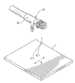
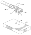
도 1은 단자 어셈블리의 실시형태의 사시도이다.
도 2는 도 1에 묘사된 크림프된(crimped) 단자의, 크림프된 단자가 회로 기판과 분리된 상태에서의 사시도이다.
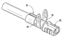
도 3은 도 2의 크림프된 단자의 사시도이다.
도 4는 도 3의 크림프되지 않은(un-crimped) 단자의 사시도이다.
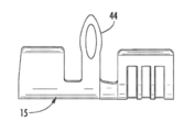
도 5는 단자의 사시도이다.
도 6a는 도 5의 단자의 평면도이다.
도 6b는 도 5의 단자의 측면도이다.
도 6c는 도 5의 단자의 정면도이다.
도 7은 단자 어셈블리의 제2의 실시형태의 사시도이다.
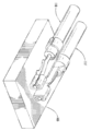
도 8은 도 7에 묘사된 크림프된 단자의, 크림프된 단자가 회로 기판과 분리된 상태에서의 사시도이다.
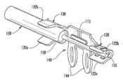
도 9는 도 8의 크림프되지 않은 단자의 사시도이다.
도 10은 도 8의 단자의 분해 사시도이다.
도 11은 단자 어셈블리의 실시형태의 사시도이다.The invention is illustrated by way of example and is not limited to the accompanying drawings, wherein like reference numerals designate like elements, wherein:
1 is a perspective view of an embodiment of a terminal assembly.
FIG. 2 is a perspective view of the crimped terminal depicted in FIG. 1 with the crimped terminal separated from the circuit board. FIG.
3 is a perspective view of the crimped terminal of FIG. 2.
4 is a perspective view of the un-crimped terminal of FIG. 3.
5 is a perspective view of a terminal.
6A is a plan view of the terminal of FIG. 5.
6B is a side view of the terminal of FIG. 5.
6C is a front view of the terminal of FIG. 5.
7 is a perspective view of a second embodiment of a terminal assembly.
8 is a perspective view of the crimped terminal depicted in FIG. 7 with the crimped terminal separated from the circuit board.
9 is a perspective view of the uncrimped terminal of FIG. 8.
10 is an exploded perspective view of the terminal of FIG. 8.
11 is a perspective view of an embodiment of a terminal assembly.
후속하는 상세한 설명은 예시적인 실시형태를 설명하며 명시적으로 개시되는 조합에 제한되도록 의도되는 것은 아니다. 따라서, 달리 언급이 없으면, 본원에서 개시되는 특징은 함께 결합되어, 간략화의 목적을 위해 달리 도시되지 않은 추가적인 조합을 형성할 수도 있다.The following detailed description describes exemplary embodiments and is not intended to be limited to the explicitly disclosed combination. Thus, unless stated otherwise, the features disclosed herein may be combined together to form additional combinations not otherwise shown for purposes of simplicity.
단자는, 첨부의 도면으로부터 알 수 있는 바와 같은 다양한 이점을 포함한다. 도 1 및 도 2에 도시된 바와 같이, 단자(10)는, 도체(55)와 절연층(58)을 포함하는 와이어(50)를 지지하며 개구(6)를 포함하는 회로 기판(5)에 탑재되도록 구성된다. 도 3 및 도 4에 더 예시된 바와 같이, 단자는 와이어와 단자를 함께 고정하도록 작용하는 베이스(15) 상의 제1의 크림프(20) 및 제2의 크림프(30)를 포함한다. 제1의 크림프(20)는 날개(22a, 22b)를 포함하고 제2의 크림프(30)는 와이어(50)를 단단히 꼭 잡도록 서로를 향해 각각 접히는 날개(32a, 32b)를 포함한다.The terminal includes various advantages as can be seen from the accompanying drawings. As shown in FIGS. 1 and 2, the
도 5에서 가장 잘 도시된 바와 같이, 한 쌍의 다리(40)는 제1의 크림프(20)와 제2의 크림프(30) 사이에 위치된다. 각각의 다리(40)는 미부(44)를 포함한다. 미부(44)는 바늘귀 디자인을 갖는 것으로 묘사되지만, 또한, 필요하다면, 단순한 관통공 디자인일 수 있을 것이다. 바늘귀 디자인의 이점은, 단자(10)가 리플로우 동작 이전에 회로 기판(5) 상에 더 확실히 위치될 수 있다는 것이다. 그러나, 종래의 바늘귀 디자인과 비교하면, 묘사된 실시형태는 바늘귀가 도금된 관통 구멍에 유지되지만 압입 구성을 제공하기 위해 사용되는 바늘귀 디자인보다는 억지 끼워맞춤(interference fit)이 덜하도록 구성될 수 있다. 예를 들면, 통상의 압입 구성은, 단자 미부 폭이 정합하는 비아의 직경보다 적어도 15% 더 크게 되도록(바람직하게는 적어도 20% 더 크게) 디자인된다. 대조적으로, 묘사된 디자인은 억지 끼워맞춤을 위해 디자인된 미부 폭을 가질 것이지만, 미부 폭이 도금된 관통 구멍의 직경보다 15% 더 큰 폭보다 더 작기 때문에, 통상적으로는 12% 더 큰 폭보다 작고 잠재적으로는 11% 더 큰 폭보다 작기 때문에, 억지 끼워맞춤은 감소된다. 또한, 유지력 외에, 미부의 개방부가 향상된 솔더 접속 및 증가된 표면적으로 인해 미부과 비아 사이에 더 나은 전기적 접속을 제공하는 데 도움이 되고, 따라서, 묘사된 디자인은 저항을 줄이고 커넥터 시스템의 성능을 향상시키는 데 도움이 되는 것으로 판명되었다.As best shown in FIG. 5, a pair of
그 디자인의 한 이점은, 크림프(30)가 절연층과 맞물리고, 이것은, 절연층(58)과 도체(55)의 조합체가 도체(55) 그 자체보다 더 강하기 때문에, 추가적인 구조적 이점을 제공한다는 것이다. 묘사된 디자인의 다른 이점은, 2개의 다리(40)가 제1의 크림프(20)와 제2의 크림프(30) 사이에서 회로 기판(5)과 맞물리고, 따라서 와이어에 인가되는 외력이 제1의 크림프(20)에 본질적으로 영향을 끼치지 않게 되는 것을 보장하는 데 도움이 된다(따라서 와이어와 단자 사이의 전기적 접속을 보호하는 데 도움이 된다). 또한, 베이스(15)의 양측 상의 2개의 미부(40)의 균형이 잡힌 구성은, 회로 기판에 대한 힘을 분산시키는 데 도움이 되고, 이것은 실제로 단자(10)와 지지 회로 기판(5) 사이의 접속을 보호할 것으로 예상된다. 한 실시형태에서, 단자(10)는, 제2의 크림프(30)는 직접적으로 회로 기판(5) 상에 위치되지만 제1의 크림프(20)는 회로 기판(5) 약간 위에 위치되도록 구성될 수 있다.One advantage of the design is that the
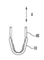
알 수 있는 바와 같이, 다리(40)는, 도 2와 도 6a 내지 도 6c에 예시된 바와 같이 회로 기판의 표면에 의해 정의되는 방향 B에 실질적으로 수직인 방향 A로 연장하는 미부(44)를 구비한다. 다르게 말하면, 미부(44)는 회로 기판(5)에 수직이거나 심지어 직교할 수 있다. 묘사된 바와 같이, 미부(44)는 지지 회로 기판(5)을 통해 연장한다. 이것은 단자(10)가 회로 기판(5)에 솔더링될 때 솔더 필릿(solder fillet)이 기판의 반대측 상에 형성되는 것을 허용하여, 유지력을 향상시키게 된다.As can be seen, the
제2의 크림프(30)는 직접적으로 회로 기판 상에 위치되지만 제1의 크림프(20)는 기판에 대해 상승되도록 베이스(15)가 구성될 수 있음을 유의해야 한다. 단자(10)에 대해 추가적인 지지를 제공하기 위해 회로 기판(5)을 사용하는 것은, 단자(10)가 회로 기판(5)으로부터 부주의하게 제거되지 않는 것을 추가로 보장하는 데 도움이 될 것으로 예상된다. 따라서, 베이스(15)는 하나의 수평면을 제공하고, 이 수평면으로부터 제1 및 제2의 크림프가 연장하지만, 묘사된 다리(40) 배향과 함께, 제2의 크림프(30)의 더 큰 크기는 제2 크림프가 지지 회로 기판과 먼저 접촉하게 하여 단자에 대해 추가적인 지지를 제공하는 것을 돕는다. 따라서, 묘사된 실시형태는 와이어가 낮은 프로파일 방식으로 지지 회로 기판에 전기적으로 연결되는 것을 허용한다.It should be noted that the
도 9 및 도 10은 다른 배치를 도시하며, 다리들(140)이 제1의 크림프(120) 및 제2의 크림프(130) 사이에 형성되고 두 다리(140)는 베이스(115)의 동일측으로부터 방향 C로 연장한다. 베이스(115)는 제1의 표면을 갖는 평판으로서 형성될 수 있고 또한 두 크림프는 이들이 제1의 표면으로부터 거리를 두고 떨어져 위치되도록 형성되어 지지될 수 있다. 이 배치에서, 단자(110)는, 다리(140)가 단자(110)의 베이스(115)와 동일 면 상에 놓여 있는 상태로 90도 회전되어 있다. 마찬가지로, 다리(140)는 수직 또는 직교 방식으로 회로 기판(105)에 형성된 도금된 구멍(106)에 수용되는 미부(144)를 구비한다. 추가적으로, 제1의 크림프(120)는 날개(122a, 122b)를 포함하고 제2의 크림프는 와이어(150)를 단단히 꼭 잡도록 서로를 향해 각각 접히는 날개(132a, 132b)를 포함한다.9 and 10 show different arrangements, in which
본질적으로, 도 7 및 도 8에 묘사된 바와 같이, 단자(110)는 제1의 크림프(120)가 회로 기판(105) 약간 위에 위치되고 제2의 크림프(130)가 직접적으로 회로 기판(105) 위에 위치되고 또한 회로 기판에 지지되는 상태로, 제1의 크림프(120)가 와이어(150)의 도체(155)와 맞물리고 제2의 크림프(130)가 와이어(150)의 도체(155)를 둘러싸는 절연층(158)과 맞물려서 옆으로 눕혀져 배치된다. 이 구성에서, 다리(140)는, 회로 기판(105)의 도금된 구멍(106) 안으로 가압되고 (위에서 논의된 바와 같이) 솔더링되도록 구성되는 바늘귀 디자인을 가지고 형성되는 미부(144)를 구비한다. 또한, 미부는 관통 구멍 구조 내에 제공될 수 있고, 여기서, 미부는 회로 기판의 반대 측에 배치된 패드와 접촉하도록 솔더링된다. 알 수 있는 바와 같이, 두 다리(140)는 베이스(115)의 동일 측에서 연장한다.In essence, as depicted in FIGS. 7 and 8, the terminal 110 has a
이전에 언급된 바와 같이, 단자(110)는 회로 기판으로부터 연장하는 단자(110)의 높이를 최소화하기 위한 낮은 프로파일 배치를 제공한다. 묘사된 바와 같이, 단자는 낮은 프로파일 구성을 유지하고, 또한 동작시, 회로 기판에 탑재되는 경우, 나란한 어레이로 배열될 때 단자 사이의 밀접한 간격을 유지한다. 도 10에 가장 잘 도시된 바와 같이, 두 다리(140)는 단자(110)의 베이스(115)로부터 방향 C로 연장하여, 리드 와이어(150)가 단자(110)로부터 멀어지는 제1의 방향으로 연장하는 것을 허용하는 것을 알 수 있다. 다른 구성에서, 다리(140)는 단자(110)의 베이스(115)의 반대측 상에서 방향 D로 연장하여 본질적으로 단자의 뒤집혀진 또는 경면 대칭 형태를 생성할 수도 있다. 이러한 경면 대칭 형태는 베이스에 대한 크림프의 위치가 경면 대칭이되게 하면서 리드 와이어(150)가 제1의 방향으로 연장될 수 있게 한다. 이 구성을 통해, 도 11에 묘사된 바와 같이, 인접한 단자는 회로 기판 상에서 등을 맞댄 배치(back-to-back arrangement)로 밀접하게 배치되어 단자 간격을 더 최소화할 수 있다. 따라서, 한 실시형태는 제1의 와이어 어셈블리와 제2의 와이어 어셈블리를 포함할 수 있고, 와이어 어셈블리들은 등을 맞댄 배향으로 회로 기판에 끼워지도록(mated) 구성되고 단자는 제1 및 제2의 다리가 양 구성에서 베이스의 동일 측으로부터 연장하도록 구성된다.As mentioned previously, the terminal 110 provides a low profile arrangement to minimize the height of the terminal 110 extending from the circuit board. As depicted, the terminals maintain a low profile configuration and, in operation, when mounted on a circuit board, maintain close spacing between the terminals when arranged in side by side arrays. As best shown in FIG. 10, the two
본원에서 제공되는 개시는 양호한 그리고 예시적인 그 실시형태의 관점에서 특징을 설명한다. 본 개시의 고찰로부터 종래기술의 당업자는, 첨부된 특허청구범위의 취지와 범위 내에 있는 수 많은 다른 실시형태, 수정예 및 변형예를 떠올릴 것이다.The disclosure provided herein describes the features in terms of their preferred and exemplary embodiments. Many other embodiments, modifications, and variations that occur within the spirit and scope of the appended claims will occur to those skilled in the art from consideration of the present disclosure.
Claims (19)
양측에 제1 단부 및 제2 단부를 갖는 베이스,
상기 제1 단부에 근접하고 상기 베이스로부터 외측으로 연장된 제1 크림프부로서, 와이어의 노출된 도체에 맞물리도록 구성된 제1 크림프부;
상기 제2 단부에 근접하고 상기 베이스로부터 외측으로 연장된 제2 크림프부로서, 와이어의 절연층에 맞물리도록 구성된 제2 크림프부; 및
상기 베이스로부터 외측으로 연장된 제1의 다리 및 제2의 다리를 포함하고,
상기 제1의 다리는 회로 기판의 대응되는 제1 개구 안으로 연장되도록 구성되고, 상기 제2의 다리는 상기 회로 기판의 대응되는 제2 개구 안으로 연장되도록 구성되는, 단자.Terminal
A base having a first end and a second end on both sides,
A first crimp portion proximate to the first end and extending outwardly from the base, the first crimp portion configured to engage an exposed conductor of a wire;
A second crimp portion proximate said second end and extending outwardly from said base, said second crimp portion configured to engage an insulating layer of wire; And
A first leg and a second leg extending outwardly from the base,
Wherein the first leg is configured to extend into a corresponding first opening of a circuit board and the second leg is configured to extend into a corresponding second opening of the circuit board.
상기 제1의 다리 및 제2의 다리 각각은 미부를 포함하고,
상기 제1의 다리 및 제2의 다리 각각의 미부는 바늘귀 구조를 갖고,
상기 미부는 상기 회로 기판의 대응되는 개구 안으로 압입(press-fit)되도록 구성된, 단자. The method according to claim 1,
Each of the first and second legs includes a tail;
Tail portions of each of the first leg and the second leg have a needle-ear structure,
The tail configured to be press-fit into a corresponding opening of the circuit board.
상기 제1 크림프부는 상기 와이어의 노출된 도체의 양측의 주위로 연장되어 접히도록 구성된 제1 날개 및 제2 날개로 형성되는, 단자. The method according to claim 1,
And the first crimp portion is formed of first and second wings configured to extend and fold around both sides of the exposed conductor of the wire.
상기 제2 크림프부는 상기 와이어의 절연층의 양측의 주위로 연장되어 접히도록 구성된 제1 날개 및 제2 날개로 형성되는, 단자. The method according to claim 1,
And the second crimp portion is formed with first and second wings configured to extend and fold around both sides of the insulating layer of the wire.
상기 제1의 다리 및 제2의 다리는 제1 크림프부 및 제2 크림프부 사이에서 상기 베이스로부터 외측으로 연장되고,
상기 제1 크림프부 및 제2 크림프부는 상기 베이스로부터 외측으로 연장되는, 단자.The method according to claim 1,
The first leg and the second leg extend outwardly from the base between the first crimp portion and the second crimp portion,
And the first crimp portion and the second crimp portion extend outwardly from the base.
상기 베이스는 마주하는 제1 및 제2 측부를 갖고,
상기 제1의 다리는 상기 베이스의 제1 측부로부터 외측으로 연장되고,
상기 제2의 다리는 상기 베이스의 제2 측부로부터 외측으로 연장되고,
상기 제1 및 제2 크림프부와 제1의 다리 및 제2의 다리는 각각 대체로 수직으로 상기 베이스로부터 외측으로 연장되는, 단자. The method according to claim 1,
The base has opposing first and second sides,
The first leg extends outward from the first side of the base,
The second leg extends outward from the second side of the base,
And the first and second crimp portions, the first and second legs, respectively, extend outwardly from the base substantially vertically.
상기 베이스는 측부를 갖고,
상기 제1의 다리 및 제2의 다리 각각은 상기 베이스의 측부로부터 외측으로 연장되고,
상기 제1 및 제2 크림프부 각각은 대체로 수직으로 상기 베이스로부터 외측으로 연장되고,
상기 제1의 다리 및 제2의 다리 각각은 대체로 수직으로 상기 베이스로부터 외측으로 연장되는, 단자.The method according to claim 1,
The base has sides,
Each of the first and second legs extends outwardly from the side of the base,
Each of the first and second crimp portions extend outwardly from the base substantially vertically;
And the first and second legs each extending outwardly from the base generally vertically.
도체를 덮는 절연층을 갖는 와이어, 및
베이스, 제1 및 제2 크림프부, 제1의 다리 및 제2의 다리를 갖는 단자를 포함하고,
상기 와이어는 제1 부분 및 제2 부분을 갖고, 제1 부분은 도체와 절연층으로 형성되고, 제2 부분은 도체 만으로 형성되고,
상기 베이스는 양측에 제1 단부 및 제2 단부를 갖고,
상기 제1 크림프부는 상기 제1 단부에 근접하고 상기 베이스로부터 외측으로 연장되고, 상기 와이어의 제2 부분에 맞물리도록 구성되고,
상기 제2 크림프부는 상기 제2 단부에 근접하고 상기 베이스로부터 외측으로 연장되고, 상기 와이어의 제1 부분에 맞물리도록 구성되고,
상기 제1의 다리 및 제2의 다리는 상기 베이스로부터 외측으로 연장되고,
상기 제1의 다리는 회로 기판의 대응되는 제1 개구 안으로 연장되도록 구성되고, 상기 제2의 다리는 상기 회로 기판의 대응되는 제2 개구 안으로 연장되도록 구성되는,
와이어 조립체.Wire assembly,
A wire having an insulating layer covering the conductor, and
A terminal having a base, first and second crimp portions, a first leg and a second leg,
The wire has a first portion and a second portion, the first portion is formed of a conductor and an insulating layer, the second portion is formed of only a conductor,
The base has a first end and a second end on both sides,
The first crimp portion proximate to the first end and extend outwardly from the base and configured to engage a second portion of the wire,
The second crimp portion proximate to the second end and extend outwardly from the base and configured to engage a first portion of the wire,
The first leg and the second leg extend outwardly from the base,
The first leg is configured to extend into a corresponding first opening of a circuit board, and the second leg is configured to extend into a corresponding second opening of the circuit board,
Wire assembly.
상기 제1의 다리 및 제2의 다리 각각은 미부를 포함하고,
상기 제1의 다리 및 제2의 다리 각각의 미부는 바늘귀 구조를 갖고,
상기 미부는 상기 회로 기판의 대응되는 적어도 하나의 개구 안으로 압입(press-fit)되도록 구성된, 와이어 조립체. The method according to claim 8,
Each of the first and second legs includes a tail;
Tail portions of each of the first leg and the second leg have a needle-ear structure,
And the tail portion is configured to press-fit into a corresponding at least one opening of the circuit board.
상기 제1 크림프부는 상기 와이어의 제2 부분의 양측의 주위로 연장되어 접히도록 구성된 제1 날개 및 제2 날개로 형성되고,
상기 제2 크림프부는 상기 와이어의 제1 부분의 양측의 주위로 연장되어 접히도록 구성된 제1 날개 및 제2 날개로 형성되는, 와이어 조립체The method according to claim 8,
The first crimp portion is formed of a first wing and a second wing configured to extend and fold around both sides of a second portion of the wire,
Wherein the second crimp portion is formed of a first wing and a second wing configured to extend and fold around both sides of the first portion of the wire
상기 제1의 다리 및 제2의 다리는 제1 크림프부 및 제2 크림프부 사이에서 상기 베이스로부터 외측으로 연장되고,
상기 제1 크림프부 및 제2 크림프부는 상기 베이스로부터 외측으로 연장되는, 와이어 조립체.The method according to claim 8,
The first leg and the second leg extend outwardly from the base between the first crimp portion and the second crimp portion,
The first crimp portion and the second crimp portion extend outwardly from the base.
상기 베이스는 마주하는 제1 및 제2 측부를 갖고,
상기 제1의 다리는 상기 베이스의 제1 측부로부터 외측으로 연장되고,
상기 제2의 다리는 상기 베이스의 제2 측부로부터 외측으로 연장되고,
상기 제1 및 제2 크림프부와 제1의 다리 및 제2의 다리는 각각 대체로 수직으로 상기 베이스로부터 외측으로 연장되는, 와이어 조립체. The method according to claim 8,
The base has opposing first and second sides,
The first leg extends outward from the first side of the base,
The second leg extends outward from the second side of the base,
Wherein the first and second crimp portions and the first and second legs extend generally outwardly from the base, generally vertically.
상기 베이스는 측부를 갖고,
상기 제1의 다리 및 제2의 다리 각각은 상기 베이스의 측부로부터 외측으로 연장되고,
상기 제1 및 제2 크림프부 각각은 대체로 수직으로 상기 베이스로부터 외측으로 연장되고,
상기 제1의 다리 및 제2의 다리 각각은 상기 베이스로부터 대체로 평행하게 외측으로 연장되는, 와이어 조립체.The method according to claim 8,
The base has sides,
Each of the first and second legs extends outwardly from the side of the base,
Each of the first and second crimp portions extend outwardly from the base substantially vertically;
Each of the first and second legs extend outwardly substantially parallel from the base.
지지 표면, 제1 개구 및 제2 개구를 갖는 회로 기판, 및
와이어 및 단자를 포함하는 와이어 조립체를 포함하고,
상기 와이어는 도체를 덮는 절연층을 갖고,
상기 와이어는 제1 부분 및 제2 부분을 갖고, 제1 부분은 도체와 절연층으로 형성되고, 제2 부분은 도체 만으로 형성되고,
상기 단자는 베이스, 제1 및 제2 크림프부, 제1의 다리 및 제2의 다리를 갖고,
상기 베이스는 양측에 제1 단부 및 제2 단부를 갖고,
상기 제1 크림프부는 상기 제1 단부에 근접하고 상기 베이스로부터 외측으로 연장되고, 상기 제1 크림프부는 상기 와이어의 제2 부분에 맞물리도록 구성되고, 상기 제1 크림프부는 상기 회로 기판의 지지 표면으로부터 이격되어 있고,
상기 제2 크림프부는 상기 제2 단부에 근접하고 상기 베이스로부터 외측으로 연장되고, 상기 제2 크림프부는 상기 와이어의 제1 부분에 맞물리도록 구성되고,
상기 제2 크림프부는 상기 회로 기판의 지지 표면에 위치하고,
상기 제1의 다리 및 제2의 다리는 상기 베이스로부터 외측으로 연장되고,
상기 제1의 다리는 상기 회로 기판의 제1 개구 안으로 연장되고,
상기 제2의 다리는 상기 회로 기판의 제2 개구 안으로 연장되는,
조립체.Assembly,
A circuit board having a support surface, a first opening and a second opening, and
A wire assembly comprising a wire and a terminal,
The wire has an insulating layer covering the conductor,
The wire has a first portion and a second portion, the first portion is formed of a conductor and an insulating layer, the second portion is formed of only a conductor,
The terminal has a base, first and second crimp portions, a first leg and a second leg,
The base has a first end and a second end on both sides,
The first crimp portion proximate to the first end and extend outwardly from the base, the first crimp portion configured to engage a second portion of the wire, the first crimp portion spaced apart from a support surface of the circuit board. It is,
The second crimp portion proximate to the second end and extend outwardly from the base, the second crimp portion configured to engage a first portion of the wire,
The second crimp portion is located on a support surface of the circuit board,
The first leg and the second leg extend outwardly from the base,
The first leg extends into the first opening of the circuit board,
The second leg extends into a second opening of the circuit board,
Assembly.
상기 제1의 다리 및 제2의 다리 각각은 미부를 포함하고,
상기 제1의 다리 및 제2의 다리 각각의 미부는 바늘귀 구조를 갖고,
상기 미부는 상기 회로 기판의 적어도 하나의 개구 안으로 압입(press-fit)되도록 구성된, 조립체. The method according to claim 14,
Each of the first and second legs includes a tail;
Tail portions of each of the first leg and the second leg have a needle-ear structure,
And the tail portion is configured to press-fit into at least one opening of the circuit board.
상기 제1 크림프부는 상기 와이어의 제2 부분의 양측의 주위로 연장되어 접히도록 구성된 제1 날개 및 제2 날개로 형성되고,
상기 제2 크림프부는 상기 와이어의 제1 부분의 양측의 주위로 연장되어 접히도록 구성된 제1 날개 및 제2 날개로 형성되는, 조립체The method according to claim 14,
The first crimp portion is formed of a first wing and a second wing configured to extend and fold around both sides of a second portion of the wire,
Wherein the second crimp portion is formed of first and second wings configured to extend and fold around both sides of the first portion of the wire
상기 제1의 다리 및 제2의 다리는 제1 크림프부 및 제2 크림프부 사이에서 상기 베이스로부터 외측으로 연장되고,
상기 제1 크림프부 및 제2 크림프부는 상기 베이스로부터 외측으로 연장되는, 조립체.The method according to claim 14,
The first leg and the second leg extend outwardly from the base between the first crimp portion and the second crimp portion,
And the first crimp portion and the second crimp portion extend outwardly from the base.
상기 베이스는 상기 회로 기판의 지지 표면에 대체로 평행하고,
상기 베이스는 마주하는 제1 및 제2 측부를 갖고,
상기 제1의 다리는 상기 회로 기판의 지지 표면을 향해 대체로 수직으로 상기 베이스의 제1 측부로부터 외부로 연장하고,
상기 제2의 다리는 상기 회로 기판의 지지 표면을 향해 대체로 수직으로 상기 베이스의 제2 측부로부터 외부로 연장하고,
상기 제1 및 제2 크림프부 각각은 상기 회로 기판의 지지 표면을 향해 대체로 수직으로 상기 베이스로부터 외측으로 연장되는, 조립체. The method according to claim 14,
The base is generally parallel to the support surface of the circuit board,
The base has opposing first and second sides,
The first leg extends outwardly from the first side of the base generally vertically towards the support surface of the circuit board,
The second leg extends outward from the second side of the base generally vertically towards the support surface of the circuit board,
Each of said first and second crimp portions extend outwardly from said base generally vertically toward a support surface of said circuit board.
상기 베이스는 상기 회로 기판의 지지 표면에 대체로 수직이고,
상기 베이스는 상기 회로 기판의 지지 표면을 마주하는 측부를 갖고,
상기 제1의 다리 및 제2의 다리 각각은 상기 회로 기판의 지지 표면을 향해 대체로 평행하게 상기 베이스의 측부로부터 외부로 연장하고,
상기 제1 및 제2 크림프부 각각은 대체로 수직으로 상기 베이스로부터 외측으로 연장되어, 상기 제1 및 제2 크림프부가 상기 회로 기판의 지지 표면에 대체로 평행인, 조립체.
The method according to claim 14,
The base is generally perpendicular to the support surface of the circuit board,
The base has a side facing the support surface of the circuit board,
Each of the first and second legs extend outwardly from the side of the base substantially parallel toward the support surface of the circuit board,
Each of said first and second crimp portions extending outwardly from said base generally vertically such that said first and second crimp portions are generally parallel to a support surface of said circuit board.
Applications Claiming Priority (5)
| Application Number | Priority Date | Filing Date | Title |
|---|---|---|---|
| US201261730385P | 2012-11-27 | 2012-11-27 | |
| US61/730,385 | 2012-11-27 | ||
| US201361825666P | 2013-05-21 | 2013-05-21 | |
| US61/825,666 | 2013-05-21 | ||
| PCT/US2013/072012 WO2014085458A1 (en) | 2012-11-27 | 2013-11-26 | Wire to board terminal |
Related Parent Applications (1)
| Application Number | Title | Priority Date | Filing Date |
|---|---|---|---|
| KR1020157016861A Division KR102173544B1 (en) | 2012-11-27 | 2013-11-26 | Wire to board terminal |
Publications (2)
| Publication Number | Publication Date |
|---|---|
| KR20200022505A true KR20200022505A (en) | 2020-03-03 |
| KR102188671B1 KR102188671B1 (en) | 2020-12-08 |
Family
ID=50828417
Family Applications (2)
| Application Number | Title | Priority Date | Filing Date |
|---|---|---|---|
| KR1020157016861A KR102173544B1 (en) | 2012-11-27 | 2013-11-26 | Wire to board terminal |
| KR1020207003944A KR102188671B1 (en) | 2012-11-27 | 2013-11-26 | Wire to board terminal |
Family Applications Before (1)
| Application Number | Title | Priority Date | Filing Date |
|---|---|---|---|
| KR1020157016861A KR102173544B1 (en) | 2012-11-27 | 2013-11-26 | Wire to board terminal |
Country Status (6)
| Country | Link |
|---|---|
| US (2) | US9362630B2 (en) |
| KR (2) | KR102173544B1 (en) |
| CN (1) | CN104995801B (en) |
| MY (1) | MY169412A (en) |
| TW (1) | TWI508385B (en) |
| WO (1) | WO2014085458A1 (en) |
Families Citing this family (11)
| Publication number | Priority date | Publication date | Assignee | Title |
|---|---|---|---|---|
| KR102173544B1 (en) * | 2012-11-27 | 2020-11-03 | 몰렉스 엘엘씨 | Wire to board terminal |
| CN104124543A (en) * | 2014-07-30 | 2014-10-29 | 株洲天利铁路机车车辆配件有限公司 | Connection method for crimping-to-welding circuit board, and connecting terminal |
| JP6621450B2 (en) * | 2017-09-13 | 2019-12-18 | 矢崎総業株式会社 | Conductor connection structure of plate-shaped wiring material |
| CN107731769A (en) * | 2017-09-27 | 2018-02-23 | 上海仪电智能电子有限公司 | A kind of package module of pin crimping |
| DE102018210234B3 (en) * | 2018-06-22 | 2019-09-19 | Würth Elektronik eiSos Gmbh & Co. KG | Contact for direct plug-in connection and direct plug-in connection |
| KR102059929B1 (en) * | 2018-10-08 | 2019-12-27 | 주식회사 유라 | Connector assembly and connector therefor |
| DE102019106022A1 (en) * | 2019-03-08 | 2020-09-10 | Alfmeier Präzision SE | Connector assembly, valve with connector assembly and method for connecting a wire to a crimp connector |
| EP4133603A4 (en) | 2020-04-07 | 2023-12-27 | Apptricity Corporation | Radio frequency (rf) location beacon with tunable antennas and cloud integration |
| US11915081B2 (en) | 2020-04-07 | 2024-02-27 | Apptricity Corporation | Flexible radio beacons and flexible delivery structures and system and method for using |
| CN112531441B (en) * | 2020-12-10 | 2022-05-17 | 深圳市创仁顺耀达精密电子有限公司 | Preparation process of wire-to-board connector terminal |
| CN113809597A (en) * | 2021-08-11 | 2021-12-17 | 中航光电科技股份有限公司 | Buckling structure and connector using same |
Citations (2)
| Publication number | Priority date | Publication date | Assignee | Title |
|---|---|---|---|---|
| CN201018025Y (en) * | 2007-03-27 | 2008-02-06 | 大同股份有限公司 | Improved structure of ring terminal |
| DE202010011546U1 (en) * | 2010-08-18 | 2010-11-04 | Erni Electronics Gmbh | Device for contacting an electrical conductor with a conductor track and contact carrier for such a device |
Family Cites Families (11)
| Publication number | Priority date | Publication date | Assignee | Title |
|---|---|---|---|---|
| US5374204A (en) * | 1993-11-30 | 1994-12-20 | The Whitake Corporation | Electrical terminal with compliant pin section |
| US5772454A (en) * | 1995-11-03 | 1998-06-30 | The Whitaker Corporation | Wire to board contact terminal |
| TW515587U (en) | 2001-05-24 | 2002-12-21 | Steve Han-Shi Hwang | Sleeved type terminal rivet and battery button using the same |
| JP4203956B2 (en) * | 2003-02-07 | 2009-01-07 | 富士通株式会社 | Power supply terminal |
| US7344388B2 (en) * | 2005-11-24 | 2008-03-18 | Hirschmann Automotive Gmbh | Press-in contact with crimp arms for a circuit board |
| US7413484B2 (en) * | 2006-08-02 | 2008-08-19 | Tyco Electronics Corporation | Electrical terminal having a compliant retention section |
| US20080166928A1 (en) * | 2007-01-10 | 2008-07-10 | Liang Tang | Compliant pin |
| KR101006562B1 (en) | 2008-06-27 | 2011-01-07 | 포항공과대학교 산학협력단 | Nucleic acid extraction method |
| KR20100011827A (en) * | 2008-07-25 | 2010-02-03 | 한국단자공업 주식회사 | Terminal |
| TWM356307U (en) | 2008-10-21 | 2009-05-01 | Alltop Technology Co Ltd | Crimp-to-connect type conductive terminal |
| KR102173544B1 (en) * | 2012-11-27 | 2020-11-03 | 몰렉스 엘엘씨 | Wire to board terminal |
-
2013
- 2013-11-26 KR KR1020157016861A patent/KR102173544B1/en active IP Right Grant
- 2013-11-26 CN CN201380061765.XA patent/CN104995801B/en active Active
- 2013-11-26 WO PCT/US2013/072012 patent/WO2014085458A1/en active Application Filing
- 2013-11-26 KR KR1020207003944A patent/KR102188671B1/en active IP Right Grant
- 2013-11-26 US US14/443,682 patent/US9362630B2/en active Active
- 2013-11-26 MY MYPI2015701622A patent/MY169412A/en unknown
- 2013-11-27 TW TW102143252A patent/TWI508385B/en not_active IP Right Cessation
-
2016
- 2016-04-19 US US15/132,370 patent/US9444164B2/en active Active
Patent Citations (2)
| Publication number | Priority date | Publication date | Assignee | Title |
|---|---|---|---|---|
| CN201018025Y (en) * | 2007-03-27 | 2008-02-06 | 大同股份有限公司 | Improved structure of ring terminal |
| DE202010011546U1 (en) * | 2010-08-18 | 2010-11-04 | Erni Electronics Gmbh | Device for contacting an electrical conductor with a conductor track and contact carrier for such a device |
Also Published As
| Publication number | Publication date |
|---|---|
| US9444164B2 (en) | 2016-09-13 |
| MY169412A (en) | 2019-04-01 |
| KR102188671B1 (en) | 2020-12-08 |
| CN104995801A (en) | 2015-10-21 |
| CN104995801B (en) | 2017-10-03 |
| TWI508385B (en) | 2015-11-11 |
| US20150288081A1 (en) | 2015-10-08 |
| KR102173544B1 (en) | 2020-11-03 |
| WO2014085458A1 (en) | 2014-06-05 |
| KR20150112936A (en) | 2015-10-07 |
| US20160233599A1 (en) | 2016-08-11 |
| TW201427188A (en) | 2014-07-01 |
| US9362630B2 (en) | 2016-06-07 |
Similar Documents
| Publication | Publication Date | Title |
|---|---|---|
| US9444164B2 (en) | Wire to board terminal | |
| US10862253B2 (en) | Circular power connectors | |
| US9204549B2 (en) | Socket, circuit board assembly, and apparatus having the same | |
| JP6951496B2 (en) | Compact high speed connector | |
| FI126231B (en) | Electrical Connector | |
| US10396481B2 (en) | Mezzanine electrical connector | |
| US9350091B2 (en) | Electrical connector and conductive terminal thereof | |
| CN106684618B (en) | Electric connector | |
| US9472905B2 (en) | Electric connector and cable connector assembly | |
| CN106329207A (en) | Electrical connector assembly and assembling method therefor | |
| US20070281507A1 (en) | IC contact for LGA socket | |
| JP2015046371A (en) | Connector | |
| US8574009B2 (en) | Compact electrical connector | |
| US7993145B1 (en) | Socket connector having electrical contact with low profile | |
| TWM376962U (en) | Electrical connector and the contact | |
| US7857627B2 (en) | Base board with golden fingers at one end and a plurality of wires attached at the other end | |
| TWI661616B (en) | Electrical connector | |
| JP2024037157A (en) | Electrical connection assemblies and electrical connection devices | |
| KR200429130Y1 (en) | Land grid array connector contact | |
| TW202025571A (en) | Electrical connector and electrical connector with the same | |
| JP2007242294A (en) | Electric connection structure |
Legal Events
| Date | Code | Title | Description |
|---|---|---|---|
| A107 | Divisional application of patent | ||
| A201 | Request for examination | ||
| E902 | Notification of reason for refusal | ||
| E701 | Decision to grant or registration of patent right | ||
| GRNT | Written decision to grant |