KR20200007794A - Surface Treatment Processing Method and Surface Treatment Processing Equipment - Google Patents
Surface Treatment Processing Method and Surface Treatment Processing Equipment Download PDFInfo
- Publication number
- KR20200007794A KR20200007794A KR1020197032031A KR20197032031A KR20200007794A KR 20200007794 A KR20200007794 A KR 20200007794A KR 1020197032031 A KR1020197032031 A KR 1020197032031A KR 20197032031 A KR20197032031 A KR 20197032031A KR 20200007794 A KR20200007794 A KR 20200007794A
- Authority
- KR
- South Korea
- Prior art keywords
- inspection
- processing
- treatment
- stress
- shot
- Prior art date
Links
Images


Classifications
-
- G—PHYSICS
- G05—CONTROLLING; REGULATING
- G05B—CONTROL OR REGULATING SYSTEMS IN GENERAL; FUNCTIONAL ELEMENTS OF SUCH SYSTEMS; MONITORING OR TESTING ARRANGEMENTS FOR SUCH SYSTEMS OR ELEMENTS
- G05B19/00—Programme-control systems
- G05B19/02—Programme-control systems electric
- G05B19/418—Total factory control, i.e. centrally controlling a plurality of machines, e.g. direct or distributed numerical control [DNC], flexible manufacturing systems [FMS], integrated manufacturing systems [IMS], computer integrated manufacturing [CIM]
- G05B19/41875—Total factory control, i.e. centrally controlling a plurality of machines, e.g. direct or distributed numerical control [DNC], flexible manufacturing systems [FMS], integrated manufacturing systems [IMS], computer integrated manufacturing [CIM] characterised by quality surveillance of production
-
- B—PERFORMING OPERATIONS; TRANSPORTING
- B24—GRINDING; POLISHING
- B24C—ABRASIVE OR RELATED BLASTING WITH PARTICULATE MATERIAL
- B24C1/00—Methods for use of abrasive blasting for producing particular effects; Use of auxiliary equipment in connection with such methods
- B24C1/10—Methods for use of abrasive blasting for producing particular effects; Use of auxiliary equipment in connection with such methods for compacting surfaces, e.g. shot-peening
-
- G—PHYSICS
- G01—MEASURING; TESTING
- G01B—MEASURING LENGTH, THICKNESS OR SIMILAR LINEAR DIMENSIONS; MEASURING ANGLES; MEASURING AREAS; MEASURING IRREGULARITIES OF SURFACES OR CONTOURS
- G01B21/00—Measuring arrangements or details thereof, where the measuring technique is not covered by the other groups of this subclass, unspecified or not relevant
- G01B21/30—Measuring arrangements or details thereof, where the measuring technique is not covered by the other groups of this subclass, unspecified or not relevant for measuring roughness or irregularity of surfaces
-
- G—PHYSICS
- G01—MEASURING; TESTING
- G01L—MEASURING FORCE, STRESS, TORQUE, WORK, MECHANICAL POWER, MECHANICAL EFFICIENCY, OR FLUID PRESSURE
- G01L1/00—Measuring force or stress, in general
- G01L1/25—Measuring force or stress, in general using wave or particle radiation, e.g. X-rays, microwaves, neutrons
-
- G—PHYSICS
- G05—CONTROLLING; REGULATING
- G05B—CONTROL OR REGULATING SYSTEMS IN GENERAL; FUNCTIONAL ELEMENTS OF SUCH SYSTEMS; MONITORING OR TESTING ARRANGEMENTS FOR SUCH SYSTEMS OR ELEMENTS
- G05B2219/00—Program-control systems
- G05B2219/30—Nc systems
- G05B2219/32—Operator till task planning
- G05B2219/32182—If state of tool, product deviates from standard, adjust system, feedback
-
- Y—GENERAL TAGGING OF NEW TECHNOLOGICAL DEVELOPMENTS; GENERAL TAGGING OF CROSS-SECTIONAL TECHNOLOGIES SPANNING OVER SEVERAL SECTIONS OF THE IPC; TECHNICAL SUBJECTS COVERED BY FORMER USPC CROSS-REFERENCE ART COLLECTIONS [XRACs] AND DIGESTS
- Y02—TECHNOLOGIES OR APPLICATIONS FOR MITIGATION OR ADAPTATION AGAINST CLIMATE CHANGE
- Y02P—CLIMATE CHANGE MITIGATION TECHNOLOGIES IN THE PRODUCTION OR PROCESSING OF GOODS
- Y02P90/00—Enabling technologies with a potential contribution to greenhouse gas [GHG] emissions mitigation
- Y02P90/02—Total factory control, e.g. smart factories, flexible manufacturing systems [FMS] or integrated manufacturing systems [IMS]
-
- Y—GENERAL TAGGING OF NEW TECHNOLOGICAL DEVELOPMENTS; GENERAL TAGGING OF CROSS-SECTIONAL TECHNOLOGIES SPANNING OVER SEVERAL SECTIONS OF THE IPC; TECHNICAL SUBJECTS COVERED BY FORMER USPC CROSS-REFERENCE ART COLLECTIONS [XRACs] AND DIGESTS
- Y02—TECHNOLOGIES OR APPLICATIONS FOR MITIGATION OR ADAPTATION AGAINST CLIMATE CHANGE
- Y02P—CLIMATE CHANGE MITIGATION TECHNOLOGIES IN THE PRODUCTION OR PROCESSING OF GOODS
- Y02P90/00—Enabling technologies with a potential contribution to greenhouse gas [GHG] emissions mitigation
- Y02P90/80—Management or planning
Abstract
표면 처리 가공 방법은, 처리 대상물에 대해서 투사재를 투사하는 쇼트 처리를 하는 쇼트 처리 공정과, 쇼트 처리가 이루어진 처리 대상물의 표면측의 상태 및 외형 치수 중 적어도 한쪽을 비파괴 검사하고, 그 검사 결과가 미리 정해진 제1 정상 범위 내이면 합격, 제1 정상 범위를 포함하도록 미리 정해진 제1 허용 범위로부터 벗어나 있으면 불합격, 제1 정상 범위로부터 벗어나 있지만 제1 허용 범위 내이면 추가 가공 대상으로 평가하는 제1 검사 공정과, 추가 가공 대상으로 평가된 처리 대상물에 대해서, 다시 쇼트 처리를 하는 추가 가공 공정을 포함한다. In the surface treatment processing method, a non-destructive inspection of at least one of a shot treatment step of performing a shot treatment for projecting a projection material onto a treatment target object, and a state and an external dimension of the surface side of the treatment target subjected to the shot treatment, and the inspection result is Passed if within the first predetermined normal range, failing if it is outside the first allowable range predetermined to include the first normal range, failing the first inspection, evaluating as an additional processing object out of the first normal range but within the first allowable range The process and the further processing process which short-processes again with respect to the process target evaluated as the further processing object are included.
Description
본 개시의 일 측면은 표면 처리 가공 방법 및 표면 처리 가공 장치에 관한 것이다.One aspect of the present disclosure relates to a surface treatment processing method and a surface treatment processing apparatus.
표면 처리 가공으로서는, 쇼트 피닝(shot peening) 가공(하기 특허 문헌 1 참조) 및 쇼트 블라스팅(shot blasting) 가공과 같은 쇼트 처리에 의한 가공(이하, 「쇼트 가공」이라고 약칭함)이 알려져 있다. 쇼트 처리는 처리 대상물에 대해서 투사재를 투사함으로써, 처리 대상물을 가공하는 처리이다. 이와 같이 처리 대상물을 가공하는 경우에 있어서는, 품질 관리를 위해서, 쇼트 처리 장치의 가동 상태를 감시하는 장치 가동 관리가 행해지거나, 쇼트 가공된 처리 대상물의 표면측의 상태 등을 측정하는 제품 관리가 행해지거나 하고 있다. As surface treatment, the processing by shot processing (henceforth abbreviating "shot processing"), such as shot peening processing (refer
그렇지만, 장치 가동 관리가 적절히 행해지고 있더라도, 예를 들면, 쇼트 가공 전의 처리 대상물의 상태가 적절하지 않은 것 등에 기인하여, 쇼트 가공된 처리 대상물에 원하는 효과가 부여되지 않는 경우도 있을 수 있다. 즉, 장치 가동 관리에서는, 쇼트 가공된 처리 대상물의 실제의 표면측의 상태 등을 직접 관리할 수 없다. 또, 제품 관리에 대해서는, 예를 들면 파괴 검사를 수반하는 경우에는 전수 검사가 아니고 일부 검사를 하지 않을 수 없어, 모든 제품에 대해 가공의 정도를 관리할 수는 없다. 이것은 시험편(試驗片) 등의 시험체를 이용하여 검사하는 경우 (예를 들면 상기 특허 문헌 1 참조)에도 마찬가지라고 할 수 있다. However, even if apparatus operation management is appropriately performed, the desired effect may not be imparted to the shot processed object, for example, due to the improper state of the processed object before shot processing. That is, in apparatus operation management, the state etc. of the actual surface side of the short process process object cannot be managed directly. In addition, about product management, when a destructive inspection is accompanied, for example, not only a whole inspection but a partial inspection is required, and the degree of processing cannot be managed about all the products. This can be said to be the same also when it examines using test bodies, such as a test piece (for example, said patent document 1).
또, 만일 쇼트 가공된 모든 처리 대상물에 대해서, 쇼트 가공의 정도를 관리할 수 있었다고 하더라도, 원하는 효과가 부여되어 있지 않은 처리 대상물을 일률적으로 폐기 대상으로 하면, 생산성이 저하된다. Moreover, even if the degree of shot processing can be managed for all the processed objects to be processed shortly, if the treated objects to which the desired effect is not given are uniformly disposed of, the productivity decreases.
본 개시의 일 측면은, 생산성을 향상시킬 수 있는 표면 처리 가공 방법 및 표면 처리 가공 장치를 제공한다. One aspect of the present disclosure provides a surface treatment processing method and a surface treatment processing apparatus that can improve productivity.
본 개시의 일 측면에 따른 표면 처리 가공 방법은, 처리 대상물에 대해서 투사재를 투사하는 쇼트 처리를 하는 쇼트 처리 공정과, 쇼트 처리가 이루어진 처리 대상물의 표면측의 상태 및 외형 치수 중 적어도 한쪽을 비파괴 검사하고, 그 검사 결과가 미리 정해진 제1 정상 범위 내이면 합격, 제1 정상 범위를 포함하도록 미리 정해진 제1 허용 범위로부터 벗어나 있으면 불합격, 제1 정상 범위로부터 벗어나 있지만 제1 허용 범위 내이면 추가 가공 대상으로 평가하는 제1 검사 공정과, 추가 가공 대상으로 평가된 처리 대상물에 대해서, 다시 쇼트 처리를 하는 추가 가공 공정을 포함한다. In the surface treatment method according to one aspect of the present disclosure, at least one of a shot treatment step of performing a shot treatment for projecting a projection material onto a treatment target object, and at least one of a state and an external dimension of the surface side of the treatment target subject to the shot treatment are non-destructive. Pass, if the test result is within the first predetermined normal range, pass, fail if it is out of the first predetermined allowable range to include the first normal range, or fail to deviate from the first normal range but further processing if within the first allowable range The 1st inspection process to evaluate as an object and the further processing process which short-processes again with respect to the process target evaluated as the further process object are included.
쇼트 처리에 의한 가공 부족이 원인으로, 처리 대상물에 원하는 효과가 부여되지 않는 경우가 있다. 이러한 경우, 재쇼트 처리에 의해 처리 대상물에 원하는 효과가 부여될 가능성이 있다. 그렇지만, 쇼트 처리에 의한 가공 부족 이외의 원인으로 원하는 효과가 부여되지 않은 처리 대상물에 대해서까지 일률적으로 재쇼트 처리가 이루어지면, 생산성이 저하된다. 상기 구성에 의하면, 쇼트 처리가 이루어진 처리 대상물의 표면측의 상태 및 외형 치수 중 적어도 한쪽이 비파괴 검사된다. 이 검사에서는, 재쇼트 처리에 의해 원하는 효과가 부여될 가능성이 있는 처리 대상물이 추가 가공 대상으로 된다. 이것에 의해, 쓸데없는 쇼트 처리를 억제하면서, 원하는 효과가 부여되는 처리 대상물의 수를 늘릴 수 있다. 따라서 생산성을 향상시킬 수 있다. Due to the shortage of processing due to the short treatment, a desired effect may not be imparted to the object to be treated. In such a case, there is a possibility that a desired effect is imparted to the object to be treated by the reshot treatment. However, if the reshot process is uniformly performed even on the object to which the desired effect is not given because of the lack of processing by the short process, productivity will fall. According to the said structure, at least one of the state and external dimension of the surface side of the process target object to which the short process was performed is non-destructive inspection. In this inspection, a further object to be processed is subject to a desired effect by the reshot treatment. As a result, it is possible to increase the number of objects to be subjected to a desired effect while suppressing unnecessary short processing. Therefore, productivity can be improved.
본 개시의 일 측면에 따른 표면 처리 가공 방법은, 제1 검사 공정에서의 검사 결과의 경시(經時) 변화의 경향에 기초하여, 제1 검사 공정에서의 검사 결과가 제1 정상 범위로부터 벗어나는 비율을 억제하도록 쇼트 처리 조건의 기준치를 재설정하는 기준치 재설정 공정을 추가로 포함해도 된다. 이 경우, 제1 검사 공정에서 합격으로 평가되는 처리 대상물의 수를 늘릴 수 있다. In the surface treatment processing method according to one aspect of the present disclosure, the rate at which the inspection result in the first inspection process deviates from the first normal range based on the tendency of the time-dependent change of the inspection result in the first inspection process. A reference value resetting step of resetting the reference value of the short treatment condition may be further included to suppress the condition. In this case, the number of objects to be evaluated as passing in the first inspection step can be increased.
본 개시의 일 측면에 따른 표면 처리 가공 방법에 있어서, 기준치 재설정 공정에서는, 제1 검사 공정에서의 검사 결과의 소정 기간마다의 평균치의 경시 변화의 경향에 기초하여, 평균치가 제1 정상 범위로부터 벗어나는 시기를 예측하여, 당해 시기보다도 전에 기준치를 재설정해도 된다. 이 경우, 제1 검사 공정에서 합격으로 평가되는 처리 대상물의 수를 효과적으로 늘릴 수 있다. In the surface treatment machining method according to one aspect of the present disclosure, in the reference value resetting step, the average value deviates from the first normal range on the basis of the tendency of the change over time of the average value for each predetermined period of the inspection result in the first inspection step. The timing may be predicted and the reference value may be reset before the timing. In this case, the number of the object to be evaluated as passing in the first inspection step can be effectively increased.
본 개시의 일 측면에 따른 표면 처리 가공 방법은, 제1 검사 공정에서의 검사 결과를 저장하는 저장 공정을 추가로 가져도 된다. 이 경우, 검사 결과의 이용성이 높아진다. The surface treatment processing method according to one aspect of the present disclosure may further have a storage step of storing the inspection result in the first inspection step. In this case, the usability of a test result becomes high.
본 개시의 일 측면에 따른 표면 처리 가공 방법은, 쇼트 처리가 이루어지기 전의 처리 대상물의 표면측의 상태 및 외형 치수 중 적어도 한쪽을 비파괴 검사하고, 그 검사 결과가 미리 정해진 제2 허용 범위로부터 벗어나 있으면 불합격으로 평가하는 제2 검사 공정을 추가로 포함해도 된다. 쇼트 처리 공정에서는, 불합격이 아니라고 평가된 처리 대상물에 대해서 쇼트 처리가 이루어져도 된다. 이 경우, 쇼트 처리가 이루어지기 전의 처리 대상물의 표면측의 상태 및 외형 치수 중 적어도 한쪽이 비파괴 검사된다. 이 검사에서는, 검사 결과가 미리 정해진 제2 허용 범위로부터 벗어나 있으면 불합격으로 평가된다. 불합격으로 평가된 처리 대상물은 미리 쇼트 처리의 대상에서 제외된다. 따라서 쓸데없는 쇼트 처리가 억제된다. In the surface treatment processing method according to one aspect of the present disclosure, at least one of the state and the outer dimensions of the surface side of the object to be treated before the short treatment is performed, and if the inspection result is out of the second predetermined allowable range, You may further include the 2nd inspection process evaluated as rejection. In the shot treatment step, the shot treatment may be performed on the treatment object evaluated as not failing. In this case, at least one of the state of the surface side and an external dimension of a process target object before a short process is performed is non-destructive inspection. In this test, if the test result deviates from the second predetermined allowable range, it is evaluated as fail. The treatment object evaluated as failing is previously excluded from the target of the short treatment. Therefore, useless short processing is suppressed.
본 개시의 일 측면에 따른 표면 처리 가공 방법은, 제2 검사 공정에서 불합격이 아니라고 평가된 처리 대상물을 대상으로 하여, 제2 검사 공정에서의 검사 결과에 따라 쇼트 처리 조건을 설정하는 조건 설정 공정을 추가로 포함해도 된다. 쇼트 처리 공정에서는, 조건 설정 공정에 있어서 설정된 쇼트 처리 조건으로 쇼트 처리가 이루어져도 된다. 이 경우, 처리 대상물에 따른 쇼트 처리를 할 수 있으므로, 생산성을 더욱 향상시킬 수 있다. The surface treatment processing method according to one aspect of the present disclosure is a condition setting step of setting a short treatment condition according to the inspection result in the second inspection process for a treatment object evaluated as not being rejected in the second inspection process. It may also be included. In the shot processing step, the shot processing may be performed under the shot processing conditions set in the condition setting step. In this case, since the short process according to a process target object can be performed, productivity can be improved further.
본 개시의 일 측면에 따른 표면 처리 가공 방법에 있어서는, 제1 검사 공정 및 제2 검사 공정은, 각각 검사 대상이 되는 처리 대상물의 표면측의 상태를 검사하기 위해서, 처리 대상물의 표면측의 잔류 응력을 측정하는 공정, 처리 대상물의 표면측을 와전류에 의해서 자성 평가하는 공정, 처리 대상물의 표면측의 색조(color tone)를 측정하는 공정 및 처리 대상물의 표면 조도(roughness)를 측정하는 공정 중 적어도 하나를 포함하고 있어도 된다. 이 경우, 쇼트 가공의 전후에 있어서의 처리 대상물의 표면측의 상태를 비파괴 검사할 수 있다. In the surface treatment processing method according to one aspect of the present disclosure, the first inspection step and the second inspection step are respectively used for residual stresses on the surface side of the object to be inspected in order to inspect the state of the surface side of the object to be inspected. At least one of a process for measuring the surface of the object to be magnetically evaluated by the eddy current, a process for measuring the color tone of the surface of the object to be treated, and a process for measuring the surface roughness of the object to be treated It may include. In this case, the non-destructive inspection can be performed on the surface side of the object to be treated before and after shot processing.
본 개시의 일 측면에 따른 표면 처리 가공 장치는, 처리 대상물에 대해서 투사재를 투사하는 쇼트 처리를 하는 투사 유닛과, 투사 유닛에 의해서 쇼트 처리가 이루어진 처리 대상물의 표면측의 상태 및 외형 치수 중 적어도 한쪽을 비파괴 검사하는 제1 검사부와, 제1 검사부의 검사 결과가 미리 정해진 제1 정상 범위 내이면 합격, 제1 정상 범위를 포함하도록 미리 정해진 제1 허용 범위로부터 벗어나 있으면 불합격, 제1 정상 범위로부터 벗어나 있지만 제1 허용 범위 내이면 추가 가공 대상으로 평가하는 제어 유닛을 구비하고 있다. 투사 유닛은 제어 유닛에 의해 추가 가공 대상으로 평가된 처리 대상물에 대해서 다시 쇼트 처리를 한다. The surface treatment apparatus according to one aspect of the present disclosure includes at least one of a projection unit that performs a shot process for projecting a projection material onto a target object, and a state and an outer dimension of the surface side of the target object that has been subjected to a short process by the projection unit. 1st inspection part which does nondestructive inspection of one side, and if the test result of a 1st inspection part is in a predetermined 1st normal range, it passes, and if it deviates from a 1st predetermined tolerance range which includes a 1st normal range, it fails from a 1st normal range. Although it deviates, it is equipped with the control unit which evaluates as an additional process object in the 1st tolerance range. The projection unit short-processes again the processing object evaluated by the control unit as a further processing object.
쇼트 처리에 의한 가공 부족이 원인으로, 처리 대상물에 원하는 효과가 부여되지 않는 경우가 있다. 이러한 경우, 재쇼트 처리에 의해 처리 대상물에 원하는 효과가 부여될 가능성이 있다. 그렇지만, 쇼트 처리에 의한 가공 부족 이외의 원인으로 원하는 효과가 부여되지 않은 처리 대상물에 대해서까지 일률적으로 재쇼트 처리가 이루어지면, 생산성이 저하된다. 상기 구성에 의하면, 쇼트 처리가 이루어진 처리 대상물의 표면측의 상태 및 외형 치수 중 적어도 한쪽이 비파괴 검사된다. 이 검사에서는, 재쇼트 처리에 의해 원하는 효과가 부여될 가능성이 있는 처리 대상물이 추가 가공 대상으로 된다. 이것에 의해, 쓸데없는 쇼트 처리를 억제하면서, 원하는 효과가 부여되는 처리 대상물의 수를 늘릴 수 있다. 따라서 생산성을 향상시킬 수 있다. Due to the shortage of processing due to the short treatment, a desired effect may not be imparted to the object to be treated. In such a case, there is a possibility that a desired effect is imparted to the object to be treated by the reshot treatment. However, if the reshot process is uniformly performed even on the object to which the desired effect is not given because of the lack of processing by the short process, productivity will fall. According to the said structure, at least one of the state and external dimension of the surface side of the process target object to which the short process was performed is non-destructive inspection. In this inspection, a further object to be processed is subject to a desired effect by the reshot treatment. As a result, it is possible to increase the number of objects to be subjected to a desired effect while suppressing unnecessary short processing. Therefore, productivity can be improved.
본 개시의 일 측면에 따른 표면 처리 가공 장치는, 제1 검사부에 의한 검사 결과를 저장하는 저장 유닛을 추가로 구비해도 된다. 이 경우, 검사 결과의 이용성이 높아진다. The surface treatment apparatus according to one aspect of the present disclosure may further include a storage unit that stores the inspection result by the first inspection unit. In this case, the usability of a test result becomes high.
본 개시의 일 측면에 따른 표면 처리 가공 방법 및 표면 처리 가공 장치에 의하면, 생산성을 향상시킬 수 있다. According to the surface treatment processing method and the surface treatment apparatus which concern on one aspect of this indication, productivity can be improved.
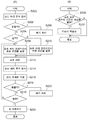
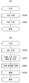
도 1의 (A)는 일련의 처리의 흐름을 나타내는 순서도이고, 도 1의 (B)는 매일의 가공 개시 전에 있어서 제어 유닛이 기동했을 때 실행되는 처리의 흐름을 나타내는 순서도이다.
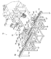
도 2는 제1 실시 형태에 따른 표면 처리 가공 방법에 이용되는 표면 처리 가공 장치를 나타내는 사시도이다.
도 3의 (A)는 도 2의 표면 처리 가공 장치의 제어계의 일부를 블록화하여 나타내는 모식도이다. 도 3의 (B)는 쇼트 피닝 가공 장치의 주요부를 간략화하여 나타내는 모식도이다.
도 4의 (A)는 자성 평가 장치의 회로 구성도이다. 도 4의 (B)는 검사 검출기의 구성을 투시 상태로 나타내는 사시도이다.
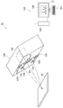
도 5는 도 2의 응력 측정 장치의 일부를 모식적인 사시도로 나타내는 개략 구성도이다.
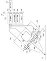
도 6은 도 2의 응력 측정 장치의 일부를 측면시(側面視)로 간략화하여 나타내는 개략 구성도이다.
도 7은 도 2의 응력 측정 장치의 검출 위치를 설명하기 위한 모식적인 도면이다.
도 8은 회절 X선에 의해서 그려지는 회절환을 설명하기 위한 도면이다.
도 9의 (A)는 잔류 응력 측정 전의 조정 처리를 나타내는 순서도이다. 도 9의 (B)는 검사 대상물의 표면측의 잔류 응력의 측정 방법을 나타내는 순서도이다.
도 10은 변형예에 따른 표면 처리 가공 장치의 제어계의 일부를 블록화하여 나타내는 모식도이다. FIG. 1A is a flowchart showing the flow of a series of processes, and FIG. 1B is a flowchart showing the flow of processes to be executed when the control unit is activated before the start of daily processing.
It is a perspective view which shows the surface treatment apparatus used for the surface treatment machining method which concerns on 1st Embodiment.
FIG. 3A is a schematic diagram showing a part of the control system of the surface treatment apparatus of FIG. 2 blocked. FIG. 3B is a schematic diagram schematically illustrating a main part of the shot peening apparatus. FIG.
4A is a circuit configuration diagram of the magnetic evaluation device. 4B is a perspective view showing the configuration of the inspection detector in a perspective view.
It is a schematic block diagram which shows a part of stress measuring apparatus of FIG. 2 in a schematic perspective view.
FIG. 6 is a schematic configuration diagram schematically showing a part of the stress measuring device of FIG. 2 in a side view. FIG.
FIG. 7: is a schematic diagram for demonstrating the detection position of the stress measuring apparatus of FIG.
8 is a diagram for explaining a diffraction ring drawn by diffraction X-rays.
9A is a flowchart showing an adjustment process before measuring residual stress. 9B is a flowchart showing a method of measuring residual stress on the surface side of an inspection object.
It is a schematic diagram which shows a block part of the control system of the surface treatment apparatus which concerns on a modification.
[제1 실시 형태][First embodiment]
본 개시의 제1 실시 형태에 따른 표면 처리 가공 방법을 도 1의 (A)~도 9의 (B)를 이용하여 설명한다. 도 2에는, 본 실시 형태에 따른 표면 처리 가공 방법에 이용되는 표면 처리 가공 장치(10)의 사시도가 도시되어 있다. 먼저, 이 표면 처리 가공 장치(10)에 대해 설명한다. 또한, 본 실시 형태의 표면 처리 가공 장치(10)에서 가공되는 처리 대상물 W로서는, 예를 들면, 금속 제품 등을 적용할 수 있다. 본 실시 형태에서는 일례로서 자동차의 트랜스미션용 기어가 적용된다. 또, 소성 가공 및 기계 가공에 의해서 제품 형상으로 된 처리 대상물(제품)이 일례로서 열처리 가공되고, 열처리 가공된 처리 대상물이, 표면 처리 가공 장치(10)에서 쇼트 피닝 가공(표면 처리 가공)되기 전의 처리 대상물 W로서, 이용된다. 그리고 이 처리 대상물 W에는, 일례로서 표면 처리 가공 장치(10)에 반입되는 단계에서 표면측에 압축 잔류 응력이 존재하고 있는 처리 대상물이 적용되고 있다. The surface treatment processing method which concerns on 1st Embodiment of this indication is demonstrated using FIG. 1 (A)-FIG. 9 (B). 2, the perspective view of the
(표면 처리 가공 장치(10)의 전체 구성)(Overall Configuration of Surface Treatment Apparatus 10)
도 2에 도시되는 것처럼, 표면 처리 가공 장치(10)는 반입측 컨베이어(12)와. 처리 전 검사 존(14)과, 두 개의 검사대(16A, 16B)와, 6축 로봇(18)과, 자성 평가 장치(20)와, 응력 측정 장치(22)를 구비하고 있다. 반입측 컨베이어(12)는 반입측 컨베이어(12)상에 재치되는 처리 대상물 W를 소정의 반송 방향(화살표 X1 참조)으로 반송한다. 반입측 컨베이어(12)의 반송 방향 중앙에는, 처리 전 검사 존(14)이 마련되어 있다. 이 처리 전 검사 존(14)에는 두 개의 검사대(16A, 16B)가 반입측 컨베이어(12)를 걸치도록 마련되어 있다. 처리 전 검사 존(14)에 있어서의 반입측 컨베이어(12)의 측방에는, 6축 로봇(18)이 배치되어 있다. As shown in FIG. 2, the
6축 로봇(18)은 처리 대상물 W를 들어 올려 이동시키는 것이 가능한 로봇이다. 6축 로봇(18)은 처리 대상물 W를 이동시켜 검사대(16A, 16B)의 위(즉 검사 위치)에 배치하는 것이 가능하다. 즉, 6축 로봇(18)은 반입측 컨베이어(12)의 위에 배치되어 있는 처리 대상물 W를 이동시켜 검사대(16A)의 위에 배치하는 것, 및 검사대(16A)의 위에 배치되어 있는 처리 대상물 W를 이동시켜 검사대(16B)의 위에 배치하는 것이 가능하다. 또, 6축 로봇(18)은 검사대(16B)의 위에 배치되어 있는 처리 대상물 W를 이동시켜 반입측 컨베이어(12)의 위(하류측)에 배치하는 것, 및 검사대(16B)의 위에 배치되어 있는 처리 대상물 W를 표면 처리 공정의 라인 밖으로 꺼내는 것이 가능하다. The 6-
또, 한쪽 검사대(16A)에는 검사 장치로서 자성 평가 장치(20)가 마련되어 있다. 다른 쪽 검사대(16B)에는 검사 장치로서 응력 측정 장치(22)가 인접 배치되어 있다. 자성 평가 장치(20) 및 응력 측정 장치(22)는, 처리 전 검사부(14E)를 구성하고 있다. 또한, 본 실시 형태에서는, 자성 평가 장치(20)가 응력 측정 장치(22)보다도 반송 방향(화살표 X1 참조)의 상류에 배치되어 있지만, 응력 측정 장치(22)가 자성 평가 장치(20)보다도 반송 방향(화살표 X1 참조)의 상류에 배치되어도 된다. Moreover, the
자성 평가 장치(20)는 검사대(16A)의 위에 배치된 처리 대상물 W에 있어서의 가공 대상부의 전체의 표면층의 상태를 검사한다. 자성 평가 장치(20)는, 예를 들면, 처리 대상물 W에 있어서의 얼룩의 유무 및 금속 조직의 상태에 대해서 와전류에 의한 평가를 행한다. 자성 평가 장치(20)는 자성 평가 장치(20)에서 행해진 검사의 결과로서, 전압치를 나타내는 신호를 출력해도 된다. 본 실시 형태의 자성 평가 장치(20)는 자성 평가 장치(20)에서 행해진 검사의 결과가, 미리 정해진 제2 정상 범위 내인지 여부를 평가(판정)한다. 자성 평가 장치(20)는 그 평가 결과를 나타내는 신호를 후술하는 제어 유닛(26)(도 3의 (A) 참조)에 출력한다. 응력 측정 장치(22)는 검사대(16B)의 위에 배치된 처리 대상물 W의 잔류 응력을, X선 회절법을 이용하여 측정한다. 본 실시 형태의 응력 측정 장치(22)는 처리 대상물 W의 전체의 응력 상태는 측정하지 않고, 지정된 측정점의 잔류 응력만을 측정한다. 응력 측정 장치(22)는 그 측정 결과(검사 결과)로서 응력치를 나타내는 신호를 후술하는 제어 유닛(26)(도 3의 (A) 참조)에 출력한다. The
이상과 같이, 처리 대상물 W가 쇼트 피닝 가공에 적합한지 여부를 판단하기 위해서, 자성 평가 장치(20)에서 처리 대상물 W의 가공 대상면 전체의 균질성이 평가됨과 아울러, 응력 측정 장치(22)에서 가공 대상 범위의 일부에 대해서 구체적인 잔류 응력이 측정된다. 또한, 자성 평가 장치(20) 및 응력 측정 장치(22)의 상세한 것에 대하여는, 후술한다. As described above, in order to determine whether the object to be processed W is suitable for shot peening, the homogeneity of the entire object surface of the object to be processed W is evaluated by the
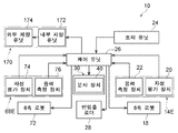
도 3의 (A)에는, 도 2의 표면 처리 가공 장치(10)의 제어계의 일부를 블록화한 구성이 모식도로 도시되어 있다. 도 3의 (A)에 도시되는 것처럼, 표면 처리 가공 장치(10)는 제어 유닛(26)을 추가로 구비하고 있다. 자성 평가 장치(20), 응력 측정 장치(22) 및 6축 로봇(18)은, 제어 유닛(26)(제어부)에 접속되어 있다. 제어 유닛(26)은, 예를 들면, 기억 장치, 및 연산 처리 장치 등을 가지고 있다. 상세 도시를 생략하지만, 상기 연산 처리 장치는, 예를 들면, CPU(Central Processing Unit), 메모리, 기억부, 및 통신 인터페이스(I/F)부를 구비하고, 이것들이 버스를 통해서 서로 접속되어 있다. 상기 기억부에는 연산 처리용 프로그램이 기억되어 있다. 또, 기억 장치와 연산 처리 장치는, 서로의 통신 인터페이스(I/F)부에 의해서 통신 가능하다. FIG. 3A is a schematic diagram showing a configuration in which a part of the control system of the
제어 유닛(26)은 자성 평가 장치(20)의 평가 결과를 자성 평가 장치(20)로부터 수신하고, 응력 측정 장치(22)의 검사 결과를 응력 측정 장치(22)로부터 수신한다. 자성 평가 장치(20)의 평가 결과는, 자성 평가 장치(20)의 검사 결과가 미리 정해진 제2 자성 정상 범위(자성에 대한 제2 정상 범위) 내인지 여부를 나타내는 정보이다. 자성 평가 장치(20)의 검사 결과가 제2 자성 정상 범위 내인지 여부에 대한 평가는, 후술하는 판단 수단(96)에 의해 행해진다. 제어 유닛(26)은 응력 측정 장치(22)에 의한 검사 결과가 미리 정해진 제2 응력 허용 범위 내(응력에 대한 제2 허용 범위)인지 여부, 및 응력 측정 장치(22)에 의한 검사 결과가 미리 정해진 제2 응력 정상 범위 내(응력에 대한 제2 정상 범위)인지 여부를 판정(평가)한다. 또한, 본 명세서에서는 「허용 범위」는, 「정상 범위」보다도 넓고, 「정상 범위」를 포함하도록 미리 설정되어 있다. 제어 유닛(26)은 자성 평가 장치(20) 및 응력 측정 장치(22)의 검사 결과가 모두 제2 정상 범위 내이면 「합격」즉 표준 쇼트 처리 조건(쇼트 피닝 가공의 조건)으로 가공 가능의 평가(판정)를 한다. 또, 제어 유닛(26)은 자성 평가 장치(20)에 의한 평가가 정상(표면이 균질한 상태)이고, 또한 응력 측정 장치(22)의 검사 결과가 규격치(제2 응력 정상 범위)를 약간 하회 또는 약간 상회하는 것의 표준 쇼트 처리 조건을 변경함으로써 정상으로 될 수 있는 처리 대상물 W에 대해서, 「조건부 합격」의 평가(판정)를 한다. 「조건부 합격」이란, 쇼트 처리 조건을 변경하여 가공 가능하다는 의미이다. 또한, 제어 유닛(26)은 「합격」에도 「조건부 합격」에도 해당하지 않는 경우(처리 전 검사부(14E)의 검사 결과가 미리 정해진 제2 허용 범위로부터 벗어나 있는 경우, 즉, 본 실시 형태에서는, 응력 측정 장치(22)의 검사 결과가 제2 응력 허용 범위로부터 벗어나 있는 경우)는 「불합격」(본 실시 형태에서는 폐기 대상)의 평가(판정)를 한다. The
즉, 제어 유닛(26)은 자성 평가 장치(20)의 검사 결과가 미리 정해진 제2 자성 정상 범위 내이고, 또한 응력 측정 장치(22)의 검사 결과가 미리 정해진 제2 응력 정상 범위 내인 경우, 「합격」으로 평가한다. 제어 유닛(26)은 자성 평가 장치(20)의 검사 결과가, 미리 정해진 제2 자성 정상 범위 내이고, 또한 응력 측정 장치(22)의 검사 결과가 미리 정해진 제2 응력 정상 범위로부터 벗어나 있지만, 미리 정해진 제2 응력 허용 범위 내인 경우, 「조건부 합격」으로 평가한다. 제어 유닛(26)은 자성 평가 장치(20)의 검사 결과가, 미리 정해진 제2 자성 정상 범위 밖인 경우, 또는 응력 측정 장치(22)의 검사 결과가 미리 정해진 제2 응력 허용 범위 밖인 경우, 「불합격」으로 평가한다. That is, when the test result of the
제어 유닛(26)은 「불합격」인 경우에는 처리 대상물 W를 표면 처리 공정의 라인 밖으로 꺼내도록, 6축 로봇(18)을 제어한다. 제어 유닛(26)은 「불합격」이외인 경우, 즉, 「합격」및 「조건부 합격」인 경우에는, 처리 대상물 W를 반입측 컨베이어(12)(도 2 참조)로 되돌리도록, 6축 로봇(18)을 제어한다. The
도 2에 도시되는 것처럼, 표면 처리 가공 장치(10)는 반입출 로더(28)와, 쇼트 피닝 가공 장치(30)(쇼트 처리 장치)를 추가로 구비하고 있다. 반입측 컨베이어(12)의 하류측에 있어서의 한쪽 측방(도면 중에서는 앞측)에는, 후술하는 반출측 컨베이어(66)의 상류측이 배치되어 있다. 반입측 컨베이어(12)의 하류측에 있어서의 다른 쪽 측방(도면 중에서는 안측)에는, 투사 유닛으로서의 쇼트 피닝 가공 장치(30)(쇼트 처리 장치)의 캐비넷(32)이 배치되어 있다. 반출측 컨베이어(66)의 반송 방향(화살표 X2 참조)은, 반입측 컨베이어(12)의 반송 방향(화살표 X1 참조)과 같은 방향으로 설정되어 있다. 캐비넷(32)은 상자 모양으로 형성되어 있다. 캐비넷(32)의 반입측 컨베이어(12) 쪽의 측벽(側壁)에는, 반입출용 개구부(32A)가 형성되어 있다. 또, 반입측 컨베이어(12)의 하류측에 있어서의 상방에는, 반입출 로더(28)(반입출 장치)가 마련되어 있다. 반입출 로더(28)는 반입측 컨베이어(12)의 위의 처리 대상물 W를 캐비넷(32)의 개구부(32A)로부터 캐비넷(32) 안으로 반입함과 아울러, 캐비넷(32) 안의 처리 대상물 W를 캐비넷(32)의 개구부(32A)로부터 반출측 컨베이어(66)의 위로 반출한다. As shown in FIG. 2, the
반입출 로더(28)는 한 쌍의 레일(28A)과, 대차(臺車, 28B)를 구비하고 있다. 한 쌍의 레일(28A)은 반입측 컨베이어(12) 및 반출측 컨베이어(66)의 각 반송 방향에 대해서 직교하는 방향으로 연장되어 있다. 대차(28B)는 한 쌍의 레일(28A)을 따라서 주행 가능하다. 대차(28B)는 도 3의 (A)에 도시되는 제어 유닛(26)에 접속되어 있다. 대차(28B)를 구동시키는 기구의 도시는 생략되어 있다. 대차(28B)의 구동은 제어 유닛(26)에 의해서 제어되고 있다. 또, 상세 설명을 생략하지만, 도 2에 도시되는 대차(28B)의 하면에는, 처리 대상물 W를 매달기 위한 현수 기구(도시 생략)가 마련되어 있다. 상기 현수 기구에 있어서 처리 대상물 W를 수취(受取) 및 주고받는 하부는, 승강 가능하다. The loading /
도 3의 (B)에는 쇼트 피닝 가공 장치(30)의 주요부가 간략화된 모식도로 도시되어 있다. 또한, 쇼트 피닝 가공 장치(30)의 기본 구성은, 일본 특개 2012-101304호 공보에 개시된 구성과 대체로 마찬가지이다. 도 3의 (B)에 도시되는 것처럼, 쇼트 피닝 가공 장치(30)는 쇼트 처리실(34)과, 제품 재치부(36)와, 분사 장치(40)를 구비하고 있다. 캐비넷(32)의 내부에는, 쇼트 처리실(34)이 형성되어 있다. 쇼트 처리실(34)에서는, 처리 대상물 W에 투사재(강구(鋼球) 등의 쇼트)를 충돌시킴으로써, 처리 대상물 W의 쇼트 피닝 가공(넓은 의미로는, 표면 가공)이 행해진다. 쇼트 처리실(34) 내의 하부에는, 처리 대상물 W가 재치되는 제품 재치부(36)가 마련되어 있다. In FIG. 3B, the principal part of the
또, 캐비넷(32) 내의 측부에는, 분사 장치(에어 노즐식 쇼트 피닝 가공기)(40)의 노즐(64)이 마련되어 있다. 분사 장치(40)는 투사재를 포함하는 압축 공기를 노즐(64)로부터 분사하여 쇼트 처리실(34)의 처리 대상물 W에 대해서 투사재를 충돌시킨다. 이하, 분사 장치(40)에 대해 간단하게 설명한다. Moreover, the nozzle 64 of the injection apparatus (air nozzle type short peening machine) 40 is provided in the side part in the
도 3의 (B)에 도시되는 것처럼, 분사 장치(40)는 투사재 탱크(42)와, 정량 공급 장치(44)와, 가압 탱크(46)를 구비한다. 투사재 탱크(42)는 정량 공급 장치(44)를 통해서 가압 탱크(46)에 접속되어 있다. 정량 공급 장치(44)는 가압 탱크(46)와의 사이에 마련된 포핏(poppet) 밸브(44I)를 가지고 있다. 포핏 밸브(44I)는 제어 유닛(26)(도 3의 (A) 참조)에 접속되어 있다. 또, 가압 탱크(46)에는, 가압 탱크(46) 내의 투사재의 양을 검지하는 도시하지 않은 레벨계가 장착되어 있다. 상기 레벨계는 제어 유닛(26)(도 3의 (A) 참조)에 접속되어 있다. 제어 유닛(26)(도 3의 (A) 참조)은 가압 탱크(46) 내의 투사재의 양이 소정치 미만이라고 상기 레벨계가 검지했을 경우에는, 정량 공급 장치(44)의 포핏 밸브(44I)를 열도록 제어한다. 포핏 밸브(44I)는 구동용 실린더(도시 생략)에 의해서 구동된다. 포핏 밸브(44I)의 개폐는 상기 레벨계의 검지 상태에 따라서 제어 유닛(26)(도 3의 (A) 참조)에 의해서 제어된다. 포핏 밸브(44I)가 열린 상태에서는, 투사재 탱크(42)로부터 정량 공급 장치(44)를 거쳐 적당량의 투사재가 가압 탱크(46)로 보내진다. As shown in FIG. 3B, the
가압 탱크(46)의 상부에는, 에어 유입구(46A)가 형성되어 있다. 이 에어 유입구(46A)에는 접속 배관(48)의 일단부가 접속되어 있다. 접속 배관(48)의 타단부는 접속 배관(50)의 유로 중간부에 접속되어 있다. 접속 배관(50)의 유로 상류측(도면 중 오른쪽)의 일단부는, 압축 공기의 공급용 컴프레서(52)(압축 공기 공급 장치)에 접속되어 있다. 즉, 가압 탱크(46)는 접속 배관(48, 50)을 통해서 컴프레서(52)에 접속되어 있다. 컴프레서(52)는 제어 유닛(26)(도 3의 (A) 참조)에 접속되어 있다. 또, 접속 배관(48)의 유로 중간부에는 에어 유량 제어 밸브(54)(전공(電空) 비례 밸브)가 마련되어 있다. 이 에어 유량 제어 밸브(54)가 열림으로써, 컴프레서(52)로부터의 압축 공기가 가압 탱크(46) 내에 공급된다. 이것에 의해, 가압 탱크(46) 내를 가압하는 것이 가능하다. An
또, 가압 탱크(46)의 하부에는, 컷 게이트(56)가 마련된 쇼트 유출구(46B)가 형성되어 있다. 이 쇼트 유출구(46B)에는 접속 배관(58)의 일단부가 접속되어 있다. 접속 배관(58)의 타단부는 접속 배관(50)의 유로 중간부에 접속되어 있다. 접속 배관(58)의 유로 중간부에는, 쇼트 유량 제어 밸브(60)가 마련되어 있다. 쇼트 유량 제어 밸브(60)로서는, 예를 들면, 마그나 밸브(magna valve) 및 믹싱 밸브 등이 적용된다. 접속 배관(50)에 있어서의 접속 배관(58)과의 합류부는, 믹싱부(50A)를 구성하고 있다. 접속 배관(50)에 있어서, 믹싱부(50A)보다도 유로 상류측(도면 중 오른쪽)으로 접속 배관(48)과의 접속부보다도 유로 하류측(도면 중 왼쪽)에는, 에어 유량 제어 밸브(62)(전공 비례 밸브)가 마련되어 있다.Moreover, the
즉, 가압 탱크(46) 내가 가압된 상태에서 컷 게이트(56) 및 쇼트 유량 제어 밸브(60)가 열리고, 또한 에어 유량 제어 밸브(62)가 열렸을 경우, 가압 탱크(46)로부터 공급된 투사재와, 컴프레서(52)로부터 공급된 압축 공기가, 믹싱부(50A)에서 혼합되어, 접속 배관(50)의 유로 하류측(도면 중 왼쪽)으로 흐른다. That is, when the
접속 배관(50)의 유로 하류측의 단부에는, 분사용(쇼트 피닝용)의 노즐(64)이 접속되어 있다. 이것에 의해, 믹싱부(50A)에 흐른 투사재는, 압축 공기와 혼합된 상태로 노즐(64)의 선단부로부터 분사된다. 에어 유량 제어 밸브(54, 62), 컷 게이트(56) 및 쇼트 유량 제어 밸브(60)는, 도 3의 (A)에 도시되는 제어 유닛(26)에 접속되어 있다. The nozzle 64 for injection (short peening) is connected to the edge part downstream of the flow path of the
도 3의 (A)에 도시되는 제어 유닛(26)에는, 처리 대상물 W를 분사 장치(40)로 쇼트 피닝 처리(쇼트 처리)하기 위한 프로그램이 미리 기억되어 있다. 표면 처리 가공 장치(10)는 제어 유닛(26)에 접속된 조작 유닛(24)을 추가로 구비하고 있다. 조작 유닛(24)은 처리 대상물 W(도 2 참조)를 쇼트 피닝 처리할 때의 쇼트 처리 조건의 기준치(표준 설정 기준치)를 입력 가능하다. 조작 유닛(24)은 입력 조작에 따른 신호를 제어 유닛(26)으로 출력한다. 그리고, 제어 유닛(26)은 조작 유닛(24)으로부터 출력된 신호, 및 자성 평가 장치(20) 및 응력 측정 장치(22)로부터 출력된 검사 결과의 신호에 기초하여, 도 3의 (B)에 도시되는 컴프레서(52), 에어 유량 제어 밸브(54, 62), 컷 게이트(56) 및 쇼트 유량 제어 밸브(60) 등을 제어한다. 즉, 도 3의 (A)에 도시되는 제어 유닛(26)은 분사 장치(40)에 의한 쇼트 처리 조건, 보다 구체적으로는 투사재의 단위 시간당 토출량(유량), 투사재를 분사하는 경우의 분사압, 분사의 타이밍, 또는 가공 시간 등을 제어한다. In the
본 실시 형태에서는, 제어 유닛(26)은 전술한 「불합격」이 아니라는 평가(판정)를 한 경우에는 그 검사 대상의 처리 대상물 W에 대해서 투사재를 투사할 때의 쇼트 처리 조건을 처리 전 검사부(14E)의 검사 결과에 따라 설정한다. 구체적으로는, 제어 유닛(26)은 「합격」판정을 받은 검사 대상의 처리 대상물 W에 대해서는 쇼트 처리 조건으로서 표준 쇼트 처리 조건(기준치)을 설정한다. 제어 유닛(26)은 「조건부 합격」 판정을 받은 검사 대상의 처리 대상물 W에 대해서는 표준 쇼트 처리 조건(기준치)을 수정한 쇼트 처리 조건을 설정한다. In this embodiment, when the
즉, 제어 유닛(26)은 「합격」판정을 받은 검사 대상의 처리 대상물 W에 대해서는 표준 쇼트 처리 조건으로 투사재를 분사(투사)하도록 분사 장치(40)를 제어한다. 제어 유닛(26)은 「조건부 합격」 판정을 받은 검사 대상의 처리 대상물 W에 대해서는 표준 쇼트 처리 조건을 수정한 쇼트 처리 조건으로 투사재를 분사(투사)하도록 분사 장치(40)를 제어한다. 보충 설명하면, 「조건부 합격」 판정을 받은 검사 대상의 처리 대상물 W 중 응력 측정 장치(22)의 검사 결과가 규격치(제2 응력 정상 범위)를 약간 하회하는 처리 대상물 W에 대해서는, 압축 잔류 응력을 보충하기 위해, 예를 들면, 분사압(투사압)이 높아지도록 표준 쇼트 처리 조건을 수정한 쇼트 처리 조건으로 투사재가 분사된다. 이것에 대해서, 「조건부 합격」 판정을 받은 검사 대상의 처리 대상물 W 중 응력 측정 장치(22)의 검사 결과가 규격치(제2 응력 정상 범위)를 약간 상회하는 처리 대상물 W에 대해서는, 압축 잔류 응력의 과대한 축적을 피하기 위해, 예를 들면, 분사압(투사압)이 낮아지도록 표준 쇼트 처리 조건을 수정한 쇼트 처리 조건으로 투사재가 분사된다. 또한, 투사재를 분사하는 경우의 분사압은, 도 3의 (B)에 도시되는 전공 비례 밸브인 에어 유량 제어 밸브(54, 62)의 입력치(에어 유량 제어 밸브(54, 62)의 개도(開度))를 제어함으로써 증감시키는 것이 가능하다. That is, the
상세 설명을 생략하지만, 제품 재치부(36)는 본 실시 형태에서는 일례로서 소위 멀티 테이블의 구조를 가지고 있다. 즉, 제품 재치부(36)에는 공전 테이블(36A)이 배치됨과 아울러, 공전 테이블(36A)상에는 공전 테이블(36A)의 동심원상의 위치에 복수의 자전 테이블(36B)이 배치되어 있다. 공전 테이블(36A)은 장치 상하 방향의 회전축(35X)을 구비하고 있다. 공전 테이블(36A)은, 회전축(35X) 둘레로 회전(공전) 가능하다. 공전 테이블(36A)은 분사 장치(40)에 의해 투사재가 분사되는 분사 범위와, 분사 범위 이외의 비분사 범위를 포함하는 위치에 배치되어 있다. 또, 자전 테이블(36B)의 직경은 공전 테이블(36A)의 직경보다도 짧다. 자전 테이블(36B)은 공전 테이블(36A)의 회전축(35X)과 평행한 회전축(35Z)을 구비하고 있다. 자전 테이블(36B)은 회전축(35Z) 둘레로 회전(자전) 가능하다. Although the detailed description is omitted, the product placement unit 36 has a so-called multi-table structure as an example in this embodiment. That is, 36 A of revolving tables are arrange | positioned at the product mounting part 36, and several rotating table 36B is arrange | positioned on the revolving table 36A in the concentric position of 36 A of revolving tables. The revolving table 36A includes a
자전 테이블(36B)에는 처리 대상물 W가 배치된다. 또, 공전 테이블(36A)에 있어서의 상기 분사 범위의 상방에는 도시하지 않은 누름 기구가 마련되어 있다. 상기 누름 기구의 누름부는 자전 테이블(36B)상의 처리 대상물 W를 상방에서 누르고 처리 대상물 W와 함께 회전 가능하다. 또, 공전 테이블(36A)을 회전(공전)시키는 공전 구동 기구(도시 생략) 및 자전 테이블(36B)을 회전(자전)시키는 자전 구동 기구(도시 생략)는, 각각 제어 유닛(26)(도 3의 (A) 참조)에 접속되어 있다. 공전 구동 기구 및 자전 구동 기구의 작동은, 각각 제어 유닛(26)(도 3의 (A) 참조)에 의해서 제어되고 있다. 이것들이 제어됨으로써, 쇼트 처리 조건의 하나인 처리 대상물 W에 대한 상대적인 투사 위치가 제어된다. The object to be processed W is disposed in the rotation table 36B. Moreover, the press mechanism not shown is provided above the said injection range in the idle table 36A. The pressing part of the pressing mechanism can press the object to be processed W on the rotating table 36B from above and can rotate with the object to be processed. Moreover, the revolving drive mechanism (not shown) which rotates (revolves) the revolving table 36A, and the rotating drive mechanism (not shown) which rotates (rotates) the rotating table 36B, respectively, are the control unit 26 (FIG. 3). Reference (A)). The operation of the idle drive mechanism and the autorotation drive mechanism are controlled by the control unit 26 (refer to FIG. 3 (A)), respectively. By controlling these, the projection position relative to the processing target W which is one of the short processing conditions is controlled.
도 2에 도시되는 것처럼, 표면 처리 가공 장치(10)는 반출측 컨베이어(66)와, 처리 후 검사 존(68)과, 두 개의 검사대(70A, 70B)와, 6축 로봇(72)과, 자성 평가 장치(74)와, 응력 측정 장치(76)를 구비하고 있다. 반출측 컨베이어(66)는 반출측 컨베이어(66)상에 재치되는 처리 대상물 W를 소정의 반송 방향(화살표 X2 참조)으로 반송한다. 반출측 컨베이어(66)의 반송 방향은 반입측 컨베이어(12)의 반송 방향(화살표 X1 참조)과 같은 방향으로 설정되어 있다. 반출측 컨베이어(66)의 반송 방향 중앙에는, 처리 후 검사 존(68)이 마련되어 있다. 이 처리 후 검사 존(68)에는, 두 개의 검사대(70A, 70B)가 반출측 컨베이어(66)를 걸치도록 마련되어 있다. 처리 후 검사 존(68)에 있어서의 반출측 컨베이어(66)의 측방에는, 6축 로봇(72)이 배치되어 있다. As shown in FIG. 2, the
6축 로봇(72)은 처리 대상물 W를 들어 올려 이동시키는 것이 가능한 로봇이다. 6축 로봇(72)은 처리 대상물 W를 이동시켜 검사대(70A, 70B)의 위(즉 검사 위치)에 배치하는 것이 가능하다. 즉, 6축 로봇(72)은 반출측 컨베이어(66)의 위에 배치되어 있는 처리 대상물 W를 이동시켜 검사대(70A)의 위에 배치하는 것, 및 검사대(70A)의 위에 배치되어 있는 처리 대상물 W를 이동시켜 검사대(70B)의 위에 배치하는 것이 가능하다. 또, 6축 로봇(72)은 검사대(70B)의 위에 배치되어 있는 처리 대상물 W를 이동시켜 반출측 컨베이어(66)의 위(하류측)에 배치하는 것, 및 검사대(70B)의 위에 배치되어 있는 처리 대상물 W를 표면 처리 공정의 라인 밖으로 꺼내는 것을 할 수 있다. The 6-
또, 한쪽 검사대(70A)에는 검사 장치로서 자성 평가 장치(74)가 마련되어 있다. 다른 쪽 검사대(70B)에는 검사 장치로서 응력 측정 장치(76)가 인접 배치되어 있다. 자성 평가 장치(74) 및 응력 측정 장치(76)는 처리 후 검사부(68E)(제1 검사부)를 구성하고 있다. 또한, 본 실시 형태에서는, 자성 평가 장치(74)가 응력 측정 장치(76)보다도 반송 방향(화살표 X2 참조)의 상류에 배치되어 있지만, 응력 측정 장치(76)가 자성 평가 장치(74)보다도 반송 방향(화살표 X2 참조)의 상류에 배치되어도 된다. Moreover, the
자성 평가 장치(74)는 검사대(70A)의 위에 배치된 처리 대상물 W에 있어서의 가공 대상부의 전체의 표면층의 상태를 검사한다. 자성 평가 장치(74)는, 예를 들면, 처리 대상물 W에 있어서의 얼룩의 유무 및 금속 조직의 상태에 대해서 와전류에 의한 평가를 행한다. 자성 평가 장치(74)는 자성 평가 장치(74)에서 행해진 검사의 결과로서, 전압치를 나타내는 신호를 출력해도 된다. 본 실시 형태의 자성 평가 장치(74)는 자성 평가 장치(74)에서 행해진 검사의 결과가, 미리 정해진 제1 자성 정상 범위(자성에 대한 제1 정상 범위) 내인지 여부를 평가(판정)한다. 자성 평가 장치(74)는 그 평가 결과를 나타내는 신호를 제어 유닛(26)(도 3의 (A) 참조)에 출력한다. 또한, 제1 자성 정상 범위는 제2 자성 정상 범위와 같아도 되고, 상이해도 된다. The
응력 측정 장치(76)는 검사대(70B)의 위에 배치된 처리 대상물 W의 잔류 응력을, X선 회절법을 이용하여 측정한다. 본 실시 형태의 응력 측정 장치(76)는 처리 대상물 W의 전체의 응력 상태는 측정하지 않고, 지정된 측정점만의 잔류 응력을 측정한다. 응력 측정 장치(76)는 그 측정 결과(검사 결과)로서 응력치를 나타내는 신호를 제어 유닛(26)(도 3의 (A) 참조)에 출력한다. 본 실시 형태에서는, 처리 후 검사 존(68)의 자성 평가 장치(74)는, 처리 전 검사 존(14)의 자성 평가 장치(20)와 마찬가지의 구성을 가지고 있다. 처리 후 검사 존(68)의 응력 측정 장치(76)는 처리 전 검사 존(14)의 응력 측정 장치(22)와 마찬가지의 구성을 가지고 있다. The
도 3의 (A)에 도시되는 것처럼, 자성 평가 장치(74), 응력 측정 장치(76) 및 6축 로봇(72)은 제어 유닛(26)에 접속되어 있다. 제어 유닛(26)은 자성 평가 장치(74)의 평가 결과를 자성 평가 장치(74)로부터 수신하고, 응력 측정 장치(76)의 검사 결과를 응력 측정 장치(76)로부터 수신한다. 자성 평가 장치(74)의 평가 결과는 자성 평가 장치(74)의 검사 결과가 미리 정해진 제1 자성 정상 범위(자성에 대한 제1 정상 범위) 내인지 여부를 나타내는 정보이다. 자성 평가 장치(74)의 검사 결과가 제1 자성 정상 범위 내인지 여부에 대한 평가는, 후술하는 판단 수단(96)에 의해 행해진다. 제어 유닛(26)은 응력 측정 장치(76)에 의한 검사 결과가 미리 정해진 제1 응력 허용 범위 내(응력에 대한 제1 허용 범위)인지 여부, 및 응력 측정 장치(76)에 의한 검사 결과가 미리 정해진 제1 응력 정상 범위 내(응력에 대한 제1 정상 범위)인지 여부를 판정(평가)한다. 또한, 제1 응력 허용 범위는, 제2 응력 허용 범위와 같아도 되고, 상이해도 된다. 또, 제1 응력 정상 범위는, 제2 응력 정상 범위와 같아도 되고, 상이해도 된다. 제1 응력 정상 범위는 응력 규격 범위라고도 불린다. As shown in FIG. 3A, the
제어 유닛(26)은 자성 평가 장치(74) 및 응력 측정 장치(76)의 검사 결과가 모두 제1 정상 범위 내(처리 후 검사부(68E)의 검사 결과가 미리 정해진 제1 정상 범위 내)이면 「합격」으로 평가(판정)한다. 제어 유닛(26)은 자성 평가 장치(74)의 검사 결과가 제1 자성 정상 범위 내이고, 또한 응력 측정 장치(76)의 검사 결과가 제2 응력 정상 범위를 벗어났지만 제1 응력 허용 범위 내이면 「추가 가공 대상」으로 평가(판정)한다. 제어 유닛(26)은 자성 평가 장치(74)의 검사 결과가 제1 자성 정상 범위 밖, 또는 응력 측정 장치(76)의 검사 결과가 제1 응력 허용 범위 밖이면 「불합격」(본 실시 형태에서는 폐기 대상)으로 평가(판정)한다. If the inspection results of the
즉, 제어 유닛(26)은 자성 평가 장치(74)의 검사 결과가, 미리 정해진 제1 자성 정상 범위 내이고, 또한 응력 측정 장치(76)의 검사 결과가 미리 정해진 제1 응력 정상 범위 내인 경우, 「합격」으로 평가한다. 제어 유닛(26)은 자성 평가 장치(74)의 검사 결과가 미리 정해진 제1 자성 정상 범위 밖인 경우, 또는 응력 측정 장치(76)의 검사 결과가 미리 정해진 제1 응력 허용 범위 밖인 경우, 「불합격」으로 평가한다. 제어 유닛(26)은 자성 평가 장치(74)의 검사 결과가 제1 자성 정상 범위 내이고, 응력 측정 장치(76)의 검사 결과가 제1 응력 정상 범위 밖이고, 또한, 제1 응력 허용 범위 내이면, 「추가 가공 대상」으로 평가한다. That is, when the test result of the
제어 유닛(26)은 「합격」인 경우에는, 처리 대상물 W를 반출측 컨베이어(66)(도 2 참조)로 되돌리도록, 6축 로봇(72)을 제어한다. 제어 유닛(26)은 「불합격」인 경우에는, 처리 대상물 W를 표면 처리 공정의 라인 밖으로 꺼내도록, 6축 로봇(72)을 제어한다. 반출측 컨베이어(66)(도 2 참조)로 되돌려진 처리 대상물 W는, 다음 공정으로 흘려 보내진다. 제어 유닛(26)은 「추가 가공 대상」인 경우에는, 당해 처리 대상물 W를 대상으로 하여, 처리 후 검사부(68E)의 검사 결과에 따라 표준의 쇼트 처리 조건(기준치)을 수정한 쇼트 처리 조건을 설정한다. 제어 유닛(26)은 「추가 가공 대상」의 판정이 된 처리 대상물 W를 리턴용 컨베이어(도시 생략) 위에 재치하도록, 6축 로봇(72)을 제어한다. 리턴용 컨베이어는 반입측 컨베이어(12)(도 2 참조) 및 반출측 컨베이어(66)(도 2 참조)와 평행하게 설치되며, 리턴용 컨베이어 상에 재치된 처리 대상물 W를 쇼트 피닝 가공 장치(30)(도 2 참조)의 정면까지 반송한다. 리턴용 컨베이어에 의해 반송된 처리 대상물 W는, 반입측 컨베이어(12)에 의해 반송된 미처리의 처리 대상물 W와 마찬가지로, 반입출 로더(28)(도 2 참조)에 의해서 캐비넷(32)(도 2 참조) 안으로 반입된다. 제어 유닛(26)은 「추가 가공 대상」의 판정이 된 처리 대상물 W에 대해서는, 표준의 쇼트 처리 조건을 수정한 쇼트 처리 조건으로 투사재를 분사(투사)하도록 분사 장치(40)를 제어한다. 이것에 의해, 「추가 가공 대상」으로 평가된 처리 대상물 W에 대해서, 분사 장치(40)가 다시 투사재를 투사하는 쇼트 처리가 실행된다. In the case of "pass", the
또, 제어 유닛(26)은 자성 평가 장치(74) 및 응력 측정 장치(76)의 검사 결과를 기억 장치에 대해 기억한다. 제어 유닛(26)은 기억 장치에 기억된 최근의 예를 들면 수십일분 (혹은 몇일분) 또는 수주간분 (본 실시 형태에서는 일례로서 20일분)의 처리 후 검사부(68E)(도 2 참조, 후술하는 처리 후 검사 공정)의 응력 측정 장치(76)에 의한 검사 결과(데이터)에 대해서, 하루마다(넓은 의미로는 「소정 기간마다」)의 평균치를 연산 처리 장치에서 연산한다. 이하, 당해 평균치를 간단하게 「응력 평균치」라고도 말한다. 응력 평균치의 연산시, 처리 후 검사부(68E)의 응력 측정 장치(76)에 의한 검사 결과 중, 후술하는 재쇼트 처리가 행해진(추가 가공 공정을 거친) 처리 대상물 W의 검사 결과가 제외된다. 또한, 재쇼트 처리가 행해진 처리 대상물 W의 검사 결과가 제외되지 않아도 된다. In addition, the
제어 유닛(26)은 추가로 응력 평균치와 응력 규격 중앙치(제1 응력 정상 범위의 중앙치)와의 차를 괴리량으로서 연산 처리 장치에서 연산한다. 제어 유닛(26)은, 연산 처리 장치에 있어서, 상기 괴리량의 증감 경향(경일(經日) 변화의 경향)을 나타내는 일차식의 기울기와 절편을, 일(가로축)과 일마다의 괴리량(세로축)으로부터 최소 이승법에 의해서 산출한다. 제어 유닛(26)은 중장기의 경향으로서 응력 측정 장치(76)의 검사 결과가 제1 응력 정상 범위(응력에 대한 제1 정상 범위)로부터 벗어나는 경향이 있는지 여부를 판단한다. 제어 유닛(26)은 응력 평균치가 미리 정해진 제1 응력 정상 범위(응력에 대한 제1 정상 범위)로부터 벗어날 것으로 예측되는 날(넓은 의미로는 「시기」)을 예측일로서 산출한다. 그리고 제어 유닛(26)은, 후술하는 소정의 타이밍에서, 처리 후 검사부(68E)(응력 측정 장치(76))에 의한 검사 결과의 경시 변화의 경향에 기초하여, 처리 후 검사부(68E)(응력 측정 장치(76))의 검사 결과가 제1 응력 정상 범위 밖이 되는 비율을 억제하도록 쇼트 처리 조건의 기준치(표준 설정 기준치)를 재설정한다. 또한, 제1 응력 정상 범위는, 제2 응력 정상 범위와 같아도 되고, 상이해도 된다. The
(자성 평가 장치(20, 74)에 대해)(About
다음에, 자성 평가 장치(20, 74)에 대해 도 4의 (A) 및 도 4의 (B)를 참조하면서 설명한다. 도 4의 (A)에는, 자성 평가 장치(20)(표면 특성 검사 장치)의 회로 구성이 도시되어 있다. 도 4의 (B)에는, 자성 평가 장치(20)의 검사 검출기(86)의 구성이 투시 상태의 사시도로 도시되어 있다. 또한, 도 2에 도시되는 자성 평가 장치(20) 및 자성 평가 장치(74)는, 마찬가지의 장치 구성이기 때문에, 도 4의 (A)의 자성 평가 장치에는 대표하여 부호 20을 부여하고 있다. Next, the
도 4의 (A)에 도시되는 것처럼, 자성 평가 장치(20)는 교류 전원(78), 교류 브릿지 회로(80) 및 평가 장치(90)를 구비하고 있다. 교류 전원(78)은 교류 브릿지 회로(80)에 가변의 주파수를 가지는 교류 전력을 공급 가능하다. As shown in FIG. 4A, the
교류 브릿지 회로(80)는 가변 저항기(82)와, 피검체(검사 대상)가 되는 처리 대상물 W(이하, 적당히 「피검체 W」라고 약칭함)에 와전류를 여기하도록 코일이 배치되는 검사 검출기(86)와, 검사 검출기(86)로부터의 출력과 비교할 때의 기준이 되는 기준 상태를 검출하는 기준 검출기(84)를 구비하고 있다. 가변 저항기(82)는 저항 RA을 저항 R1과 저항 R2로 분배비 γ로 분배할 수 있다. 분배비 γ는 가변이다. 저항 R1 및 저항 R2는, 기준 검출기(84) 및 검사 검출기(86)와 함께 브릿지 회로를 구성하고 있다. 본 실시 형태에서는 점 A 및 점 B가 자성 평가 장치(20)의 교류 전원(78)에 접속되고, 점 C 및 점 D가 증폭기(91)에 접속되어 있다. 점 A는 저항 R1과 저항 R2를 분배하는 점이다. 점 B는 기준 검출기(84)와 검사 검출기(86)의 사이에 위치하고 있다. 점 C는 저항 R1과 기준 검출기(84)의 사이에 위치하고 있다. 점 D는 저항 R2와 검사 검출기(86)의 사이에 위치하고 있다. 또, 노이즈의 저감을 위해서, 기준 검출기(84) 및 검사 검출기(86)측이 접지되어 있다. 또한, 가변 저항기(82) 및 기준 검출기(84)는 일례로서 회로 기판(88)상에 배치되어 있다. The
평가 장치(90)는 증폭기(91)와, 절대치 회로(92)와, 로우패스필터(LPF)(93)와, 위상 비교기(94)와, 주파수 조정기(95)와, 판단 수단(96)과, 표시 수단(97)과, 온도 측정 수단(98)을 구비하고 있다. 증폭기(91)는 교류 브릿지 회로(80)로부터 출력되는 전압 신호를 증폭한다. 절대치 회로(92)는 전파(全波) 정류를 행한다. LPF(93)는 직류 변환을 행한다. 위상 비교기(94)는 교류 전원(78)으로부터 공급되는 교류 전압과 증폭기(91)로부터 출력되는 전압의 위상을 비교한다. 주파수 조정기(95)는 교류 전원(78)으로부터 공급되는 교류 전압의 주파수를 조정한다. 판단 수단(96)은 저항 R1과 저항 R2의 분배를 최적화하는 비평형 조정을 행한다. 추가로 판단 수단(96)은 LPF(93)로부터의 출력을 자성 평가 장치(20, 74)의 검사 결과로서 수신한다. 판단 수단(96)은 당해 검사 결과에 기초하여 처리 대상물 W의 표면 상태의 양부(良否)를 판단한다. 구체적으로는, 판단 수단(96)은 당해 검사 결과가 미리 정해진 제2 자성 정상 범위 내 또는 제1 자성 정상 범위 내인지 여부를 평가(판정)한다. 처리 대상물 W의 표면 상태가 균질(均質)한 상태이면, 자성 평가 장치(20, 74)의 검사 결과는 제2 자성 정상 범위 내 또는 제1 자성 정상 범위 내가 된다. 표시 수단(97)은 판단 수단(96)에 의한 평가 결과를 표시 및 경고한다. 온도 측정 수단(98)은 평가 위치의 온도를 검출한다. The
증폭기(91)는 점 C 및 점 D에 접속되어 있다. 증폭기(91)에는 점 C와 점 D 사이의 전위차가 입력된다. 증폭기(91)의 출력은 절대치 회로(92)에 접속되어 있다. 절대치 회로(92)의 출력은 LPF(93)에 접속되어 있다. LPF(93)의 출력은 판단 수단(96)에 접속되어 있다. 위상 비교기(94)는 교류 전원(78), 증폭기(91) 및 판단 수단(96)에 접속되어 있다. 주파수 조정기(95)는 교류 전원(78) 및 증폭기(91)에 접속되어 있다. 또, 판단 수단(96)은 제어 신호를 출력함으로써, 교류 브릿지 회로(80)의 점 A의 위치, 즉, 저항 R1과 저항 R2의 분배비 γ를 변경할 수 있다.The
온도 측정 수단(98)은 비접촉식의 적외 센서 또는 열전쌍(thermocouple) 등으로 이루어지고, 피검체 W의 표면의 온도 신호를 판단 수단(96)에 출력한다. 판단 수단(96)은 온도 측정 수단(98)에서 검출된 피검체 W의 온도가 소정 범위 내인 경우에, 피검체 W의 표면 처리 상태의 양부를 판단한다. 판단 수단(96)은 온도 측정 수단(98)에서 검출된 온도가 소정 범위 밖인 경우, 피검체(처리 대상물) W의 표면 처리 상태의 양부의 판단을 행하지 않는다. The temperature measuring means 98 consists of a non-contact infrared sensor, a thermocouple, etc., and outputs the temperature signal of the surface of the to-be-tested object W to the determination means 96. FIG. The judging means 96 judges the quality of the surface treatment state of the subject W when the temperature of the subject W detected by the temperature measuring means 98 is in a predetermined range. When the temperature detected by the temperature measuring means 98 is outside the predetermined range, the judging means 96 does not judge whether the surface treatment state of the object (the object to be treated) W is in a good condition.
검사 검출기(86) 및 기준 검출기(84)는 마찬가지의 구성을 가지고 있다. 이들 검사 검출기(86) 및 기준 검출기(84)로서는, 피검체 W의 평가부를 삽입/통과 가능한 코어의 외주(外周)에 코일이 권회(卷回)되어 형성된 검출기가 이용된다. 이 검출기는 코일을 피검체 W의 표면과 대향시켜 근접시킴으로써, 피검체 W에 와전류를 여기 가능하다. 즉, 이 코일은 피검체 W의 표면 특성 검사 영역을 둘러싸도록 권회되고, 피검체 W의 표면 특성 검사 영역과 대향하고 있다. 여기서, 피검체 W의 표면 특성 검사 영역을 둘러싼다는 것은, 적어도 표면 특성 검사 영역의 일부를 포위함(에워싸도록 둘러쌈)으로써, 표면 특성 검사 영역에 와전류를 여기하는 것을 포함하는 것을 의미하고 있다.The
도 4의 (B)에 도시되는 것처럼, 검사 검출기(86)는 코어(86A)와, 코일(86B)을 구비하고 있다. 코어(86A)는 원통 모양이고, 피검체 W(도면 중에서는 모식화하여 원주체(圓柱體)로서 도시)를 덮도록 배치되어 있다. 코일(86B)은 코어(86A)의 외주면에 권회된 에나멜 동선(銅線)으로 이루어져 있다. 또한, 본 실시 형태에서는, 코일(86B)이 권회된 코어(86A)를 둘러싸도록, 원통 모양의 자기 실드(86C)가 마련되어 있다. 코어(86A)는 비자성 재료, 예를 들면, 수지에 의해 형성되어 있다. 또한, 코어(86A)의 형상은, 피검체 W를 내측에 배치할 수 있는 형상이면 원통 형상이 아니어도 된다. 또, 검사 검출기(86)는 코일(86B)이 형상을 유지할 수 있으면 코어(86A)를 구비하고 있지 않아도 된다. As shown in FIG. 4B, the
코일(86B)이 피검체 W의 검사 대상면(표면 특성 검사 영역)을 둘러쌈과 아울러, 코일(86B)이 피검체 W의 검사 대상면과 대향하도록, 검사 검출기(86)가 배치된다. 이 상태에서, 교류 전원(78)(도 4의 (A) 참조)에 의해 코일(86B)에 소정의 주파수의 교류 전력을 공급하면 교류 자계가 발생한다. 이 결과, 피검체 W의 표면에 교류 자계에 교차하는 방향으로 흐르는 와전류가 여기된다. 와전류는 잔류 응력층의 전자기 특성에 따라 변화한다. 이 때문에, 잔류 응력층의 특성(표면 처리 상태)에 따라 증폭기(91)(도 4의 (A) 참조)로부터 출력되는 출력 파형(전압 파형)의 위상 및 진폭(임피던스)이 변화한다. 이 출력 파형의 변화에 의해 표면 처리층의 전자기 특성을 검출하여, 검사를 행할 수 있다. The
즉, 도 4의 (A)에 도시되는 평가 장치(90)는 교류 브릿지 회로(80)로부터의 출력 신호에 기초하여, 피검체 W의 표면 특성을 평가한다. 이때, 교류 브릿지 회로(80)는 교류 브릿지 회로(80)에 교류 전력이 공급됨으로써, 검사 검출기(86)가 피검체 W의 전자기 특성을 검출하고, 또한 기준 검출기(84)가 기준 상태를 검출하고 있는 상태에 있다. 평가 장치(90)의 판단 수단(96)은, 제어 유닛(26)에 접속되어 있다. 판단 수단(96)은 평가 결과에 따른 신호를 제어 유닛(26)으로 출력한다. 또한, 판단 수단(96)은 온도 측정 수단(98)에서 검출된 온도가 소정 범위 밖으로서 판단을 회피했을 경우에 대해서는, 「검사 불가」인 취지의 신호를 제어 유닛(26)에 출력한다. 이것에 의해, 판단 수단(96)은 검사에 의한 판정 결과를 낼 수 없었던 것을 제어 유닛(26)에 통지한다.That is, the
판단 수단(96)은 「검사 불가」인 취지의 신호를 표시 수단(97)에 출력한다. 표시 수단(97)은 이 신호를 수신하여, 판단 수단(96)에 의한 평가 결과로서 「검사 불가」인 취지를 표시 및 경고한다. 이것에 의해, 예를 들면, 작업원이 자성 평가 장치(20, 74)를 점검하여, 필요에 따라서 동작 환경을 개선한 후, 자성 평가 장치(20, 74)를 다시 동작시켜도 된다. 또 예를 들면, 작업원이 평가 장치(90)에 의한 검사 결과를 무효화하고, 자성 평가 장치(20, 74)를 다시 동작시켜도 된다. 이것에 의해, 피검체 W의 표면 특성을 다시 평가할 수 있다. The judging means 96 outputs to the display means 97 the signal of "non-inspection". The display means 97 receives this signal, and displays and warns that "inspection is impossible" as an evaluation result by the determination means 96. Thereby, for example, a worker may check the
<자성 평가 장치(20)를 이용한 검사 방법><Inspection Method Using
다음에, 자성 평가 장치(20)를 이용한 검사 방법에 대해 개설(槪說)한다. 먼저, 교류 전원(78)으로부터 교류 브릿지 회로(80)에 교류 전력이 공급된 상태에서, 피검체 W에 와전류가 여기되도록, 피검체 W에 대해서 검사 검출기(86)를 배치, 또는 검사 검출기(86)에 대해서 피검체 W를 배치한다(배치 공정). 즉, 먼저 배치된 피검체 W를 포위하도록 검사 검출기(86)를 배치하던지, 먼저 배치된 검사 검출기(86) 안에 피검체 W를 삽입하여 배치한다. 다음에, 교류 브릿지 회로(80)로부터 출력된 출력 신호에 기초하여, 평가 장치(90)가 피검체 W의 표면 특성을 평가한다(평가 공정). 그리고, 평가된 결과가 평가 장치(90)로부터 제어 유닛(26)으로 출력된다. Next, an inspection method using the
또한, 와전류에 의한 자성 평가에 대해서는, 예를 들면, 일본 특표 2013-529286호 공보, 일본 특표 2015-525336호 공보, 또는 국제 공개 제2015/107725호 팜플렛 등에 개시된 장치를 적용하여 자성 평가하는 것이 가능하다. In addition, about the magnetic evaluation by eddy current, it is possible to apply magnetic evaluation by applying the apparatus disclosed in Unexamined-Japanese-Patent No. 2013-529286, 2015-525336, or international publication 2015/107725 pamphlet. Do.
(응력 측정 장치(22, 76)에 대해)(About stress measuring
다음에, 응력 측정 장치(22, 76)에 대해서, 도 5~도 9의 (B)를 참조하면서 설명한다. 또한, 도 2에 도시되는 응력 측정 장치(22) 및 응력 측정 장치(76)는, 마찬가지의 장치 구성이기 때문에, 도 5의 응력 측정 장치에는 대표하여 부호 22를 부여하고 있다. Next, the
도 5에는 응력 측정 장치(22)의 일부가 모식적인 사시도로 도시되어 있다. 도 6에는 응력 측정 장치(22)의 일부가 측면시로 간략화하여 도시되어 있다. 도 5에 도시되는 것처럼, 응력 측정 장치(22)는 장치 본체(100) 및 제어 장치(150)를 구비하고 있다. 5 shows a part of the
장치 본체(100)는 상자 모양의 케이스이다. 본 실시 형태에서는, 장치 본체(100)의 내부에 X선 발생원(102)이 수용되어 있다. X선 발생원(102)은 X선 관구(管球)를 구비하고, 소정 파장의 X선을 발생시키는 장치이다. 본 실시 형태에서는, X선 발생원(102)은 장치 본체(100)에 고정되어 있다. 응력 측정 장치(22)에서는, 검사 대상의 처리 대상물 W(이하, 적당히 「검사 대상물 W」라고 약칭함.)에 맞추어 적당한 파장의 X선이 이용된다. 장치 본체(100)의 전면(前面)(100F)에는, X선 조사용의 창(도시 생략)이 형성되어 있다. X선 발생원(102)에서 발생한 X선은, 상기 창을 통해서 검사 대상물 W로 조사된다. 또한, 도 5 및 도 6에서는, X선 발생원(102)으로부터 검사 대상물 W로의 X선의 경로 및 조사 방향(입사 방향)은, 화살표선 Xa로 나타내진다. The
장치 본체(100)는 제1 검출 소자(106) 및 제2 검출 소자(108)를 구비하고 있다. 제1 검출 소자(106) 및 제2 검출 소자(108)는, 여기에서는 장치 본체(100)의 전면(100F)측에 배치되어 있다. 제1 검출 소자(106) 및 제2 검출 소자(108)는, 검사 대상물 W의 회절 X선의 강도를 각각 검출한다. 제1 검출 소자(106)는 0차원의 X선 강도 측정 소자이다. 0차원이란 소자의 배치 위치에서 X선의 강도를 측정한다는 의미이다. 즉, 제1 검출 소자(106)는 복수의 소자가 직선을 따라서 배치된 1차원의 라인 센서 및 복수의 소자가 평면에 배치된 2차원의 이미징 플레이트와는 상이하다. 제2 검출 소자(108)도 0차원의 X선 강도 측정 소자이다. 제1 검출 소자(106) 및 제2 검출 소자(108)로서, 예를 들면, 신틸레이션 카운터가 이용된다. The apparatus
장치 본체(100)는 제1 검출 소자(106) 및 제2 검출 소자(108)를 X선의 입사 방향과 직교하는 방향을 따라서 (화살표 X3 방향 참조) 각각 이동시키는 이동 기구(120)를 구비하고 있다. 도 6에 도시되는 것처럼, 이동 기구(120)는 변위 구동용 전동 모터(122)와, 볼 나사 기구(124)를 가지고 있다. The apparatus
전동 모터(122)는 장치 본체(100)에 고정되어 있다. 볼 나사 기구(124)는 X선의 입사 방향과 직교하는 방향(화살표 X3 방향 참조)을 따라서 연장되는 직선 모양의 나사(126)와, 이 나사(126)에 나사 결합된 제1 너트(128) 및 제2 너트(130)를 가지고 있다. 나사(126)는 그 축선(軸線) 둘레로 회전 가능하게 지지되어 있다. 나사(126)는 전동 모터(122)가 구동되면, 구동력 전달 기구(도시 생략)를 통해서 구동력이 전달됨으로써, 자신의 축선 둘레로 회전한다. 또한, 나사(126)는 X선 발생원(102)으로부터의 입사 X선에 대해서 가로 방향으로(도 6의 지면(紙面)에 수직인 방향으로) 오프셋된 위치에 배치되어 있다. 제1 너트(128)에는 제1 슬라이더(132)가 고정되어 있다. 제2 너트(130)에는 제2 슬라이더(134)가 고정되어 있다. 제1 슬라이더(132) 및 제2 슬라이더(134)는 한 쌍의 레일(136)(도 5 참조)에 의해서 한 쌍의 레일(136)의 연장 방향으로 슬라이드 가능하게 지지되어 있다. 한 쌍의 레일(136)은 장치 본체(100)의 전면(100F)에 마련되고, 나사(126)와 평행한 방향(X선의 입사 방향과 직교하는 방향)으로 연장되어 있다. 또한, 도 5에서는 한 쌍의 레일(136)을 모식화하여 나타냈지만, 한 쌍의 레일(136)에는 공지의 한 쌍의 가이드 레일을 적용할 수 있다. The
도 6에 도시되는 것처럼, 제1 슬라이더(132)에는 제1 검출 소자(106)가 고정되어 있다. 제2 슬라이더(134)에는 제2 검출 소자(108)가 고정되어 있다. 전동 모터(122)가 구동되면, 제1 너트(128) 및 제1 슬라이더(132)와 제2 너트(130) 및 제2 슬라이더(134)가 나사(126)에 대해서 그 축선 방향으로 상대 이동한다. 이것에 의해, 제1 검출 소자(106) 및 제2 검출 소자(108)가, 동기하여 X선의 입사 방향과 직교하는 방향으로 (화살표 X3 방향 참조) 각각 이동된다. 즉, 이동 기구(120)에 의해서, 제1 검출 소자(106) 및 제2 검출 소자(108)는, X선 강도의 검출 위치를 직선상에서 변경할 수 있다. As shown in FIG. 6, the
제1 검출 소자(106)는 검사 대상물 W의 회절 X선의 강도를 제1 검출 위치에서 검출한다. 제2 검출 소자(108)는 검사 대상물 W의 회절 X선의 강도를 제1 검출 위치와는 상이한 제2 검출 위치에서 검출한다. 제1 검출 위치 및 제2 검출 위치는, 예를 들면, 검사 대상물 W의 재료 및 초점 거리에 따라 변화시킬 수 있다. 본 실시 형태에서는, 제1 검출 소자(106) 및 제2 검출 소자(108)는, 미리 설정된 동일한 거리를 동기하여 이동한다. 미리 설정된 거리는 필요한 회절 강도 분포를 얻을 수 있는 범위의 거리이다. The
이동 기구(120)는, 도 5에 도시되는 제어 장치(150)에 접속되어 있다. 제어 장치(150)는, 예를 들면, CPU, ROM(Read Only Memory), RAM(Random Access Memory) 및 HDD(Hard Disk Drive) 등을 구비한 범용적인 컴퓨터로 구성되어 있다. 제어 장치(150)는 처리 장치(152), 입력 장치(154)(예를 들면, 키보드 및 마우스) 및 출력 장치(156)(예를 들면, 디스플레이)를 구비하고 있다. 도 6에 도시되는 것처럼, 처리 장치(152)는 입출력부(160), 이동 제어부(162), 응력 산출부(164) 및 기억부(166)를 구비하고 있다. The moving
입출력부(160)는 네트워크 카드 등의 통신 기기 및 그래픽 카드 등의 입출력 장치이다. 예를 들면, 입출력부(160)는 전동 모터(122)와 통신 가능하게 접속되어 있다. 입출력부(160)는, 예를 들면, 도 5에 도시되는 입력 장치(154) 및 출력 장치(156)와 통신 가능하게 접속되어 있다. 또, 도 6에 도시되는 입출력부(160)는 X선 발생원(102), 제1 검출 소자(106) 및 제2 검출 소자(108)에 접속되어 있다. 후술하는 이동 제어부(162) 및 응력 산출부(164)는, 입출력부(160)를 통해서 각 구성요소와 정보의 교환을 행한다. The input /
이동 제어부(162)는 이동 기구(120)를 구동시켜(이동 기구(120)의 구동을 제어함으로써) 제1 검출 소자(106) 및 제2 검출 소자(108)의 각각의 검출 위치를 제어한다. 이동 제어부(162)는 검사 대상물 W를 구성하는 재료에 기초하여 정해지는 피크 출현 각도를 미리 취득하여, 피크 출현 각도를 포함하도록, 제1 검출 소자(106) 및 제2 검출 소자(108)의 각각의 검출 위치를 제어한다. 검사 대상물 W를 구성하는 재료에 기초하여 정해지는 피크 출현 위치는, 기억부(166)에 기억되어 있다. 또, 응력 산출부(164)는 이동 기구(120)에 의해 제1 검출 소자(106) 및 제2 검출 소자(108)가 각각 이동함으로써 각각 검출된 회절 X선의 강도 피크에 기초하여, 검사 대상물 W의 잔류 응력을 산출한다. 이하, 잔류 응력의 산출에 대해 상세하게 설명한다. The
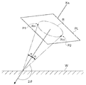
도 7은 본 실시 형태에 따른 응력 측정 장치(22)의 검출 위치를 설명하기 위한 개요도이다. 도 7에서는, 검사 대상물 W에 대해서 입사 X선 XIN가 조사되어, 회절각 2θ로 회절 X선이 출력되는 경우를 나타내고 있다. 이 경우, 소정 평면 PL에 있어서 회절 X선에 의해서 회절환 R이 그려진다. 여기서, 본 실시 형태에서는, 회절 X선의 회절환의 0°에 대응하는 검출 위치, 및 회절 X선의 회절환의 180°에 대응하는 검출 위치의 각각에서 강도 피크가 출현하고, 이 부분(즉 대칭이 되는 점)의 회절 강도를 취득하는 경우를 예로 한다. 7 is a schematic diagram for explaining a detection position of the
도 8은 회절환을 설명하기 위한 개요도이다. 도 7 및 도 8에 도시되는 것처럼, 회절환 R의 0°에 대응하는 제1 검출 위치 P1에서는, 회절 X선 XR1가 검출된다. 회절환 R의 180°에 대응하는 제2 검출 위치 P2에서는, 회절 X선 XR2가 검출된다. 이 경우, 이동 제어부(162)(도 6 참조)는 회절환 R의 0°에 대응하는 제1 검출 위치 P1를 포함하는 범위를 제1 검출 소자(106)(도 6 참조)가 이동하도록 설정한다. 마찬가지로, 이동 제어부(162)(도 6 참조)는 회절환 R의 180°에 대응하는 제2 검출 위치 P2를 포함하는 범위를 제2 검출 소자(108)(도 6 참조)가 이동하도록 설정한다. 이것에 의해, 한 번의 X선의 조사로 2각도의 회절 X선을 얻어, 두 개의 X선 회절 강도 분포를 얻을 수 있다.8 is a schematic diagram for explaining a diffraction ring. As shown in FIG. 7 and FIG. 8, at the first detection position P1 corresponding to 0 ° of the diffraction ring R, diffraction X-ray X R1 is detected. At the second detection position P2 corresponding to 180 ° of the diffraction ring R, diffraction X-ray X R2 is detected. In this case, the movement control unit 162 (see FIG. 6) sets the first detection element 106 (see FIG. 6) to move the range including the first detection position P1 corresponding to 0 ° of the diffraction ring R. . Similarly, the movement control unit 162 (see FIG. 6) sets the second detection element 108 (see FIG. 6) to move a range including the second detection position P2 corresponding to 180 ° of the diffraction ring R. Thereby, two angles of diffraction X-rays can be obtained by irradiation of one X-ray, and two X-ray diffraction intensity distributions can be obtained.
응력 산출부(164)(도 6 참조)는 제1 검출 위치 P1 및 제2 검출 위치 P2의 각각에서 검출된 X선 회절 강도 분포(각도 및 강도의 관계)에 기초하여, 회절 피크를 취득한다. 여기에서는, 회절환 R의 0°에 대응하는 강도 피크, 및 회절환 R의 180°에 대응하는 강도 피크의 두 개의 강도 피크를 얻을 수 있다. 도 8에 도시되는 2점 쇄선의 회절환 RR은, 검사 대상물 W에 잔류 응력이 존재하지 않는 경우의 회절환이다. 잔류 응력이 존재하는 경우의 회절환 R에서는, 잔류 응력이 존재하지 않는 경우의 회절환 RR에 비해, 잔류 응력에 따라 중심 위치가 어긋난다. The stress calculator 164 (see FIG. 6) acquires a diffraction peak based on the X-ray diffraction intensity distribution (relationship between angle and intensity) detected at each of the first detection position P1 and the second detection position P2. Here, two intensity peaks of an intensity peak corresponding to 0 ° of the diffraction ring R and an intensity peak corresponding to 180 ° of the diffraction ring R can be obtained. The diffraction ring R R of the two-dot chain line shown in FIG. 8 is a diffraction ring when no residual stress exists in the test object W. FIG. In the diffraction ring R when residual stress exists, the center position shifts according to the residual stress as compared with the diffraction ring R R when no residual stress exists.
응력 산출부(164)(도 6 참조)는 이 차를 이용하여 잔류 응력치를 산출한다. 예를 들면, 응력 산출부(164)(도 6 참조)는 cosα법을 이용하여 잔류 응력치를 산출한다. cosα법에서는,ε-cosα선도의 기울기로부터 잔류 응력이 얻어진다. ε-cosα선도는, cosα(α:회절 중심각)와 회절환상의 네 지점(α,π+α,-α,π-α)의 변형(distortion)(εα,επ + α,ε- α,επ -α)을 이용하여 나타내지는 변형 ε의 관계를 나타낸다. The stress calculator 164 (see FIG. 6) calculates the residual stress value using this difference. For example, the stress calculator 164 (see FIG. 6) calculates the residual stress value using the cosα method. In the cosα method, the residual stress is obtained from the slope of the ε-cosα diagram. The ε-cosα diagram is a distortion (ε α , ε π + α , ε - α , ε of cosα (α: diffraction center angle) and four points (α, π + α, -α, π-α) of the diffraction ring. The relationship of the deformation | transformation epsilon represented using ( pi )-( alpha )) is shown.
응력 산출부(164)(도 6 참조)는 α=0°, 180°의 2점을 이용하여 ε-cosα선도의 기울기(일차 함수의 기울기)를 산출한다. 그리고, 응력 산출부(164)(도 6 참조)는 일차 함수의 기울기에, X선 응력 측정 승수를 곱하여 잔류 응력을 얻는다. X선 응력 측정 승수는 영률(Young's modulus), 푸아송비(Poisson's ratio), 브랙각(Bragg angle)의 여각 및 X선 입사각에 의해서 정해지는 상수로서, 도 6에 도시되는 기억부(166)에 미리 기억되어 있다. 응력 산출부(164)는 산출한 잔류 응력치를, 입출력부(160)를 통해서 제어 유닛(26)으로 출력한다. 또한, 응력 산출부(164)에서 산출된 잔류 응력치는 제어 유닛(26)으로 출력됨과 아울러, 기억부(166)에 기억되어도 되고, 출력 장치(156)(도 5 참조)로 출력되어도 된다. The stress calculation unit 164 (see FIG. 6) calculates the slope (the slope of the linear function) of the epsilon -cosα diagram using two points of α = 0 ° and 180 °. The stress calculator 164 (see FIG. 6) multiplies the slope of the linear function by the X-ray stress measurement multiplier to obtain residual stress. The X-ray stress measurement multiplier is a constant determined by Young's modulus, Poisson's ratio, Bragg angle excitation angle and X-ray incidence angle, which is previously stored in the
<응력 측정 장치(22)를 이용한 잔류 응력 측정 방법><Residual stress measuring method using the
다음에, 응력 측정 장치(22)를 이용한 잔류 응력 측정 방법을 설명한다. 도 9의 (A) 및 도 9의 (B)는, 본 실시 형태에 따른 잔류 응력 측정 방법을 나타내는 순서도이다.Next, the residual stress measuring method using the
처음에, 잔류 응력 측정 전의 조정 처리가 실행된다. 도 9의 (A)는 잔류 응력 측정 전의 조정 처리를 나타내는 순서도이다. 도 9의 (A)에 도시되는 것처럼, 먼저, 각도 조정 처리(스텝 S240)가 실행된다. 이 처리에서는, 검사 대상물 W에 대한 입사 X선의 각도가 조정된다. 예를 들면, 도 6에 도시되는 것처럼, 장치 본체(100)를 기울여 플랩각(flap angle) θ1을 조정함으로써, 입사 X선의 각도가 조정된다. 또한, 장치 본체(100)를 기울이는 처리는, 일례로서, 별도의 장치(제어부 및 액츄에이터)가 행한다. 도 9의 (A)에 도시되는 각도 조정 처리(스텝 S240)에 의해, 측정 중의 입사 각도가 소정 각도(단일 각도)로 고정된다. Initially, the adjustment process before residual stress measurement is performed. 9A is a flowchart showing an adjustment process before measuring residual stress. As shown in Fig. 9A, first, an angle adjustment process (step S240) is performed. In this process, the angle of the incident X-ray with respect to the test object W is adjusted. For example, as shown in FIG. 6, the angle of the incident X-ray is adjusted by tilting the apparatus
다음에, 초점 조정 처리(스텝 S242)가 실행된다. 이 처리에서는, 검사 대상물 W에 대한 입사 X선의 초점이 조정된다. 예를 들면, 장치 본체(100)(도 6 참조)의 위치가 변경됨으로써, 입사 X선의 초점이 조정된다. 또한, 높이 및 위치를 변경하는 처리는, 일례로서, 별도의 장치(제어부 및 액츄에이터)가 행한다. Next, focus adjustment processing (step S242) is executed. In this process, the focus of the incident X-rays to the inspection object W is adjusted. For example, by changing the position of the apparatus main body 100 (see FIG. 6), the focus of the incident X-rays is adjusted. In addition, the process of changing a height and a position is performed by another apparatus (control part and actuator) as an example.
도 9의 (A)에 도시되는 순서도가 종료되면, 응력 측정 장치(22)는 검사 대상물 W의 표면측의 잔류 응력을 측정 가능한 상황이 된다. 도 9의 (B)는 검사 대상물 W의 표면측의 잔류 응력의 측정 방법을 나타내는 순서도이다.When the flowchart shown to FIG. 9A is complete | finished, the
도 9의 (B)에 도시되는 것처럼, 처음에 X선 조사 처리(스텝 S250:X선 조사 공정)가 실행된다. 이 X선 조사 처리(스텝 S250)에서는, X선 발생원(102)으로부터 검사 대상물 W에 X선을 조사한다. 다음에, 이 X선 조사 처리(스텝 S250)의 실행 중에 있어서 측정 처리(스텝 S252:이동 제어 공정)가 실행된다. 이 측정 처리(스텝 S252)에서는, 이동 제어부(162)에 의한 제어로 이동 기구(120)를 구동시켜 제1 검출 소자(106) 및 제2 검출 소자(108)를 이동시키고(이동 제어 공정), 이동 중인 제1 검출 소자(106) 및 제2 검출 소자(108)의 검출 결과에 기초하여, 두 개의 X선 회절 강도 분포를 얻는다. 이 공정에서는 제1 검출 소자(106)의 이동과 제2 검출 소자(108)의 이동을 동기시키고 있다. 측정 처리(스텝 S252)가 종료되었을 경우, X선의 조사를 종료해도 된다. As shown in FIG. 9B, an X-ray irradiation process (step S250: X-ray irradiation step) is first performed. In this X-ray irradiation process (step S250), X-rays are irradiated to the inspection object W from the
다음에, 잔류 응력 산출 처리(스텝 S254:응력 산출 공정)가 실행된다. 이 잔류 응력 산출 처리(스텝 S254)에서는, 측정 처리(스텝 S252:이동 제어 공정)의 실행 중에 제1 검출 소자(106) 및 제2 검출 소자(108)가 각각 검출한 검사 대상물 W의 회절 X선의 강도 피크에 기초하여, 검사 대상물 W의 잔류 응력이 산출된다. 즉, 잔류 응력 산출 처리(스텝 S254)에서는, 응력 산출부(164)에 의해, 이동 중에 얻어진 두 개의 X선 회절 강도 분포에 기초하여, 두 개의 강도 피크가 취득된다. 그리고, 응력 산출부(164)에 의해서, ε-cosα선도의 기울기가 산출되고, X선 응력 측정 승수가 곱해져 잔류 응력이 산출된다. 마지막으로, 응력 산출부(164)에 의해 산출된 잔류 응력이 제어 유닛(26)(도 3의 (A) 참조)으로 출력된다(스텝 S256). Next, a residual stress calculation process (step S254: stress calculation step) is performed. In this residual stress calculation process (step S254), the diffraction X-rays of the inspection object W detected by the
이상으로 도 9의 (B)에 도시되는 순서도가 종료된다. 도 9의 (B)에 나타내는 제어 처리를 실행함으로써, 제1 검출 소자(106) 및 제2 검출 소자(108)를 이동시켜 얻어진 데이터를 이용하여 잔류 응력을 산출하고, 산출한 잔류 응력을 제어 유닛(26)(도 3의 (A) 참조)으로 출력할 수 있다.This is the end of the flowchart shown in FIG. 9B. By performing the control process shown in FIG. 9B, the residual stress is calculated using the data obtained by moving the
이상과 같이, 도 6에 도시되는 응력 측정 장치(22)에서는, 회절 X선의 강도를 제1 검출 위치 P1(도 7 참조)에서 검출하는 제1 검출 소자(106), 및 회절 X선의 강도를 제1 검출 위치 P1(도 7 참조)과는 상이한 제2 검출 위치 P2(도 7 참조)에서 검출하는 제2 검출 소자(108)를 구비하므로, 한 번의 X선의 조사(단일 각도의 조사)로 2각도의 회절 X선을 얻을 수 있다. 또한, 제1 검출 소자(106) 및 제2 검출 소자(108)의 각각은, X선의 입사 방향과 직교하는 방향을 따라서 이동함으로써, X선 강도 분포(회절 피크)를 소자마다 취득할 수 있다. 또, 적어도 두 개의 회절 피크를 취득함으로써, 검사 대상물 W의 잔류 응력을 산출할 수 있다. 이 때문에, 이미징 플레이트를 회전시켜 회절환의 모든 데이터를 취득할 필요가 없다. 따라서 종래의 잔류 응력 측정 장치와 비교해서, 잔류 응력의 측정 시간의 단축을 도모할 수 있다. As described above, in the
또, 본 실시 형태에 따른 응력 측정 장치(22)는 이미징 플레이트를 회전시키는 기구 및 판독 기구를 구비할 필요가 없다. 이 때문에, 응력 측정 장치(22)는 그러한 기구를 구비하는 잔류 응력 측정 장치와 비교해서, 간략화되고 경량화되므로, 설치하기 쉽고, 다른 기계에 편입되기 쉬운 구조로 할 수 있다. 또한, 응력 측정 장치(22)에서는, 장치 구성이 간략화됨으로써, 종래의 잔류 응력 측정 장치와 비교해서, 장치의 제조 코스트를 저감시킬 수 있다. In addition, the
또한, 이동 제어부(162)가 제1 검출 소자(106)의 이동과 제2 검출 소자(108)의 이동을 동기시킴으로써, 제1 검출 소자(106)와 제2 검출 소자(108)를 개별적으로 제어하는 경우에 비해 잔류 응력의 측정 시간의 단축을 도모할 수 있다. In addition, the
(표면 처리 가공 장치(10)를 이용한 표면 처리 가공 방법에 대해)(About surface treatment processing method using surface treatment apparatus 10)
다음에, 도 2에 도시되는 표면 처리 가공 장치(10)를 이용한 표면 처리 가공 방법에 대해서, 도 1의 (A) 및 도 1의 (B)에 도시되는 순서도 및 도 2 등을 참조하면서 설명한다. 표면 처리 가공 장치(10)는, 도 4의 (A) 등에 도시되는 자성 평가 장치(20), 도 5 등에 도시되는 응력 측정 장치(22), 및 도 3의 (B) 등에 도시되는 쇼트 피닝 가공 장치(30) 등을 포함하고 있다. 또한, 도 2에 도시되는 표면 처리 가공 장치(10)에 반입되기 전의 처리 대상물 W로서, 소성 가공 및 기계 가공에 의해서 제품 형상으로 된 처리 대상물(제품)이 일례로서 열 처리 가공되어 있다. Next, the surface treatment method using the
도 2에 도시되는 표면 처리 가공 장치(10)에 반입된 처리 대상물 W는, 반입측 컨베이어(12)상에 재치되어 반송된다. 처리 대상물 W는 처리 전 검사 존(14)에 도달하면, 6축 로봇(18)에 의해서 검사대(16A)의 위에 배치되어 자성 평가 장치(20)에 의해 검사된다. 그 후, 처리 대상물 W는 6축 로봇(18)에 의해서 검사대(16B)의 위에 배치되어 응력 측정 장치(22)에 의해 검사된다. The process target object W carried in to the
즉, 검사대(16A, 16B)의 위에 있어서, 도 1의 (A)의 스텝 S200에 나타내는 쇼트 처리 전의 검사, 즉 처리 전 검사 공정(제2 검사 공정)이 실행된다. 이 처리 전 검사 공정에서는, 처리 대상물 W에 대해서 투사재를 투사하는 쇼트 처리가 행해지기 전의 당해 처리 대상물 W의 표면측의 상태가 비파괴 검사된다. 그 검사 결과가 미리 정해진 제2 허용 범위로부터 벗어나 있는 경우에 「불합격」으로 평가된다. That is, on the inspection tables 16A and 16B, the inspection before the short process shown in step S200 of FIG. 1A, that is, the inspection process before treatment (second inspection process) is executed. In this pre-processing inspection process, the non-destructive inspection of the state of the surface side of the said processing target object W before the short process which projects the projection material with respect to the processing target object W is performed. If the test result deviates from the second predetermined allowable range, it is evaluated as "failed".
먼저, 도 2에 도시되는 검사대(16A)상에서는, 자성 평가 장치(20)가 처리 대상물 W의 표면측을 와전류에 의해서 자성 평가하는 검사를 한다. 구체적인 검사 방법은 상술한 대로이다. 자성 평가 장치(20)에서는 검사 결과에 기초하여 판단 수단(96)이 표면 상태의 양부를 판단한다. 자성 평가 장치(20)는 검사 결과(즉, 판단 수단(96)의 평가 결과)를 제어 유닛(26)(도 3의 (A) 참조)에 출력한다. 다음에, 검사대(16B)상에서는, 응력 측정 장치(22)가 처리 대상물 W의 표면측의 잔류 응력을, X선 회절법을 이용하여 측정한다. 구체적인 측정 방법은 상술한 대로이다. 응력 측정 장치(22)는 측정 결과를 제어 유닛(26)(도 3의 (A) 참조)에 출력한다. 제어 유닛(26)은 자성 평가 장치(20) 및 응력 측정 장치(22)의 검사 결과에 기초하여, 전술한 것처럼 「합격」, 「조건부 합격」, 및 「불합격」 중 어느 하나의 평가를 한다. First, on the inspection stand 16A shown in FIG. 2, the
도 1의 (A)에 나타내는 스텝 S202에 있어서, 제어 유닛(26)은 처리 대상물 W가 「불합격」인지 여부를 판정한다. 제어 유닛(26)의 처리는, 스텝 S202의 판정이 긍정된 경우는, 스텝 S206으로 이행하고, 스텝 S202의 판정이 부정된 경우는 스텝 S204로 이행한다. 스텝 S206에 있어서, 제어 유닛(26)은 처리 대상물 W를 표면 처리 공정의 라인 밖으로 꺼내도록, 도 2에 도시되는 6축 로봇(18)을 제어한다. 라인 밖으로 꺼내진 처리 대상물 W는 폐기 처리된다. 즉, 처리 전 검사 공정에서 「불합격」으로 평가된 처리 대상물 W는 미리 쇼트 처리의 대상에서 제외된다. 이것에 의해, 무익한 쇼트 피닝 가공(불량 제품의 가공)이 미연에 억제된다. In step S202 shown in FIG. 1A, the
도 1의 (A)에 나타내는 스텝 S204에 있어서, 제어 유닛(26)은 처리 대상물 W가 「합격」인지 여부를 판정한다. 제어 유닛(26)의 처리는, 스텝 S204의 판정이 부정된 경우는 스텝 S210으로 이행하고, 스텝 S204의 판정이 긍정된 경우는 스텝 S208로 이행한다. 스텝 S208 및 스텝 S210에 있어서는, 조건 설정 공정이 실행된다. 처리 전 검사 공정의 후에 실행되는 조건 설정 공정에서는, 처리 전 검사 공정에서 「불합격이 아님」으로 평가된 처리 대상물 W를 대상으로 하여 처리 전 검사 공정에서의 검사 결과에 따라 제어 유닛(26)이 쇼트 처리 조건을 설정한다. In step S204 shown in FIG. 1A, the
스텝 S210에 있어서는, 제어 유닛(26)은 「조건부 합격」으로 판정된 처리 대상물 W의 쇼트 처리 조건으로서, 표준 쇼트 처리 조건을 수정한 조건(조정된 조건)을 설정한다(피드 포워드)(조건 설정 공정). 즉, 개별의 쇼트 피닝 가공 전의 처리 대상물 W(제품)의 성상(性狀)에 맞추어 개별로(하나의 부품마다) 쇼트 처리 조건이 조정된다. 이것에 의해, 표준 쇼트 처리 조건인 채로 가공했을 경우에 불량품이 될 수 있는 처리 대상물 W를 우량품으로 하는 것이 가능해진다. 이것에 의해, 폐기 처분되는 처리 대상물 W를 줄일 수 있다. 따라서 생산성을 향상시킬 수 있다. In step S210, the
「조건부 합격」으로 판정된 처리 대상물 W의 쇼트 처리 조건의 수정(조정)에 대해 보다 구체적으로 설명한다. 본 실시 형태에서는, 쇼트 처리 조건 중 일례로서 투사재를 분사하는 경우의 분사압에 대해 수정한 조건이 설정된다. 이 쇼트 처리 조건의 수정 조건(수정치)은, 이하와 같이 연산된다. 먼저, 제어 유닛(26)의 연산 처리 장치에 있어서, 그 기억부에 미리 기억되어 있은 연산식을 포함하는 프로그램이 읽어내져 메모리에 전개된다. 다음에, 메모리에 전개된 당해 프로그램이 CPU에 의해서 실행된다. 이것에 의해, 수정 조건이 연산된다. 연산식은 쇼트 처리 조건의 기준치를 포함한 식이다. 또한, 변형예로서, 조건 판별을 포함하는 프로그램을 제어 유닛(26)의 연산 처리 장치에 미리 기억시켜, 이 프로그램을 실행함으로써 쇼트 처리 조건의 수정 조건을 결정해도 된다.Correction (adjustment) of the short process conditions of the process target object W determined as "conditional acceptance" is demonstrated more concretely. In this embodiment, the modified condition about the injection pressure at the time of injecting a projection material is set as an example of shot processing conditions. The correction condition (correction value) of this short processing condition is calculated as follows. First, in the arithmetic processing unit of the
한편, 스텝 S208에 있어서는, 제어 유닛(26)은 「합격」으로 판정된 처리 대상물 W의 쇼트 처리 조건으로서, 표준 쇼트 처리 조건을 그대로 설정한다. 스텝 S210 및 스텝 S208에 의해 처리 대상물 W에 따른 쇼트 가공을 할 수 있다.On the other hand, in step S208, the
「합격」또는 「조건부 합격」으로 판정된 처리 대상물 W는, 도 2에 도시되는 6축 로봇(18)에 의해서, 검사대(16B)의 위로부터 반입측 컨베이어(12)의 위로 이동된다. 그 후, 처리 대상물 W는 반입측 컨베이어(12)의 하류측에서 반입출 로더(28)에 의해서 쇼트 피닝 가공 장치(30)의 캐비넷(32) 안으로 반입된다. The processing target W determined as "passed" or "conditionally passed" is moved from the top of the inspection table 16B to the carry-in
쇼트 피닝 가공 장치(30)의 캐비넷(32) 안에서는, 도 1의 (A)에 나타내는 스텝 S212, 즉 쇼트 처리 공정이 실행된다. 조건 설정 공정의 후에 실행되는 쇼트 처리 공정에서는, 처리 대상물 W에 대해서 도 3의 (B)에 도시되는 쇼트 피닝 가공 장치(30)의 분사 장치(40)가 투사재를 투사하는 쇼트 처리가 행해진다. 쇼트 처리 공정에 있어서의 쇼트 처리 조건은, 처리 전 검사 공정에서 제어 유닛(26)에 의해서 「불합격이 아님」으로 평가된 처리 대상물 W를 대상으로 하여, 조건 설정 공정에서 제어 유닛(26)에 의해서 설정된다.In the
여기서, 쇼트 처리에 대해 개략적으로 설명한다. 쇼트 처리로서는, 예를 들면 쇼트 피닝(가공) 및 쇼트 블라스팅(가공)이 있다. 이들 쇼트 처리에서는, 예를 들면 수십μm에서 수mm 정도의 대략 구형 투사재(쇼트(연마 입자를 포함함))가 처리 대상물 W를 향해서 고속으로 부딪혀진다. 이것에 의해, 처리 대상물 W의 부품 표면층의 개선 효과가 얻어진다. 쇼트 피닝 가공은 반복하여 하중을 받는 부품의 피로 강도(fatigue strength)(내구성) 개선 등을 목적으로 사용되고 있다. 반복 하중을 받는 부품으로서, 예를 들면, 자동차, 항공기, 선박, 건설 기계, 가공 기계, 및 강구조물 등을 들 수 있다. 쇼트 피닝 가공은 올바르게 실시되어 있지 않으면, 목표로 한 표면 경도(硬度), 경도 분포, 및 압축 잔류 응력 등이 부품에 부여되지 않아, 부품이 조기에 파괴되어 버리는 경우도 있다. 따라서 적절한 가공을 유지하기 위해서, 충분한 관리를 한 다음 쇼트 피닝 가공을 실시할 필요가 있다. 또, 쇼트 블라스팅 가공은 동일한 가공품에 대해서, 예를 들면 녹 및 스케일 등의 표면의 부착물의 제거, 표면 조도 등의 표면 형상의 조정, 도장(塗裝) 및 코팅 피막 등의 밀착성 향상, 또는 강구조물의 마찰 결합부에 있어서의 적절한 마모 계수의 확보를 위해서 사용되고 있다. 따라서 쇼트 피닝 가공과 마찬가지로 충분한 관리를 한 다음 쇼트 블라스팅 가공을 실시할 필요가 있다. 또한, 본 실시 형태에 있어서의 쇼트 처리의 가공은 쇼트 피닝 가공이다.Here, the short process will be described schematically. Examples of the shot treatment include shot peening (processing) and shot blasting (processing). In these shot treatments, a substantially spherical projection material (shot (including abrasive grains)) of, for example, several tens of micrometers to several mm is hit at high speed toward the object to be treated. Thereby, the improvement effect of the component surface layer of the process target object W is acquired. Shot peening is used for the purpose of improving the fatigue strength (durability) of parts which are repeatedly loaded. As a part which receives a cyclic load, an automobile, an aircraft, a ship, a construction machine, a processing machine, a steel structure, etc. are mentioned, for example. If the shot peening is not carried out correctly, the target surface hardness, hardness distribution, compressive residual stress, and the like are not imparted to the part, and the part may be destroyed prematurely. Therefore, in order to maintain proper processing, it is necessary to perform a short peening processing after sufficient management. In addition, shot blasting is performed on the same workpiece, for example, removal of deposits on the surface such as rust and scale, adjustment of surface shape such as surface roughness, improvement of adhesion such as coating and coating film, or steel structure. It is used to secure an appropriate wear factor in the frictional joint. Therefore, as with shot peening, it is necessary to perform sufficient management and then perform shot blasting. In addition, the process of the shot process in this embodiment is a shot peening process.
쇼트 처리된 처리 대상물 W는, 도 2에 도시되는 반입출 로더(28)에 의해서 쇼트 피닝 가공 장치(30)의 캐비넷(32) 안에서 반출측 컨베이어(66)의 상류측으로 반출된다. 처리 대상물 W는 반출측 컨베이어(66)에 의해서 반송된다. 처리 대상물 W는 처리 후 검사 존(68)에 도달하면, 6축 로봇(72)에 의해서 검사대(70A)의 위에 배치되어 자성 평가 장치(74)로 검사된다. 그 후, 처리 대상물 W는 6축 로봇(72)에 의해서 검사대(70B)의 위에 배치되어 응력 측정 장치(76)로 검사된다. The shot processing object W is carried out to the upstream side of the carrying-out
즉, 검사대(70A, 70B)의 위에 있어서, 도 1의 (A)의 스텝 S214에 나타내는 쇼트 처리 후의 검사, 즉 처리 후 검사 공정(제1 검사 공정)이 실행된다. 쇼트 처리 공정 후의 처리 후 검사 공정에서는, 처리 대상물 W의 표면측의 상태가 비파괴 검사된다. 그 검사 결과가 미리 정해진 제1 정상 범위 내이면 「합격」으로 평가되고, 미리 정해진 제1 허용 범위로부터 벗어나면 「불합격」으로 평가되고, 상기 제1 정상 범위로부터 벗어났지만, 상기 제1 허용 범위 내이면 「추가 가공 대상」으로 평가된다.That is, on the inspection tables 70A and 70B, the inspection after the shot process shown in step S214 of FIG. 1A, that is, the post-process inspection process (first inspection process) is executed. In the post-processing inspection process after the shot treatment process, the state on the surface side of the object to be treated is nondestructively inspected. If the test result is within the first predetermined range, the result is evaluated as "passed". If the test result falls outside the predetermined first allowable range, the result is evaluated as "failed", and is out of the first normal range, but within the first allowable range. It is evaluated as "the further processing object".
도 2에 도시되는 검사대(70A)상에서는, 자성 평가 장치(74)가 처리 대상물 W의 표면측을 와전류에 의해서 자성 평가하는 검사를 한다. 구체적인 검사 방법은 상술한 대로이다. 자성 평가 장치(74)에서는 검사 결과에 기초하여 판단 수단(96)이 표면 상태의 양부를 판단한다. 자성 평가 장치(74)는 검사 결과(즉, 판단 수단(96)의 평가 결과)를 제어 유닛(26)(도 3의 (A) 참조)에 출력한다. 다음에, 검사대(70B)상에서는, 응력 측정 장치(76)가 처리 대상물 W의 표면측의 잔류 응력을, X선 회절법을 이용하여 측정한다. 구체적인 측정 방법은 상술한 대로이다. 응력 측정 장치(76)는 측정 결과를 제어 유닛(26)(도 3의 (A) 참조)에 출력한다. 제어 유닛(26)은 자성 평가 장치(74) 및 응력 측정 장치(76)의 검사 결과에 기초하여, 전술한 것처럼 「합격」,「불합격」및 「추가 가공 대상」중 어느 하나의 평가를 한다.On the inspection stand 70A shown in FIG. 2, the
또, 도 1의 (A)에 나타내는 스텝 S214의 다음 스텝 S216에 있어서, 제어 유닛(26)은 응력 측정 장치(76)의 검사 결과(측정치)를 기억 장치에서 기억한다. 스텝 S216의 다음 스텝 S218에 있어서는, 제어 유닛(26)은 처리 대상물 W가 「불합격」인지 여부(즉, 처리 후 검사 공정의 검사 결과가 제1 허용 범위 내인지 여부)를 판정한다. 제어 유닛(26)의 처리는, 스텝 S218의 판정이 긍정된 경우는 스텝 S222로 이행하고, 스텝 S218의 판정이 부정된 경우는 스텝 S219로 이행한다.In addition, in step S216 of step S214 shown in FIG. 1A, the
스텝 S219에 있어서는, 제어 유닛(26)은 처리 대상물 W가 「합격」인지 여부(즉, 처리 후 검사 공정의 검사 결과가 제1 정상 범위 내인지 여부)를 판정한다. 스텝 S219의 판정이 긍정된 경우는, 제어 유닛(26)의 처리는, 스텝 S220으로 이행한다. 스텝 S219의 판정이 부정된 경우는, 제어 유닛(26)은 처리 대상물 W를 「추가 가공 대상」으로 판정한다. 그리고 제어 유닛(26)의 처리는 스텝 S208로 이행한다. 스텝 S208에 있어서는, 조건 설정 공정이 실행된다. 처리 후 검사 공정 후에 실행되는 조건 설정 공정에서는, 처리 후 검사 공정에서 「추가 가공 대상」으로 평가된 처리 대상물 W를 대상으로 하여, 제어 유닛(26)이 쇼트 처리 조건으로서, 표준의 쇼트 처리 조건을 설정한다. In step S219, the
「추가 가공 대상」으로 판정된 처리 대상물 W는, 6축 로봇(72), 리턴용 컨베이어 및 반입출 로더(28)에 의해서, 검사대(70B) 위에서 쇼트 피닝 가공 장치(30)로 반송된다. 쇼트 피닝 가공 장치(30)에서는, 스텝 S212, 즉 쇼트 처리 공정이 실행된다. 여기에서는, 스텝 S208의 조건 설정 공정에서 설정된 쇼트 처리 조건으로 쇼트 처리가 이루어진다. 이것에 의해, 「추가 가공 대상」으로 판정된 처리 대상물 W에 대해서, 추가 가공 공정이 실행된다. 또한, 「추가 가공 대상」으로 판정된 처리 대상물 W의 쇼트 처리 조건으로서, 표준의 쇼트 처리 조건을 수정한 조건이 설정되어도 된다(피드 포워드). 즉, 스텝 S219의 판정이 부정된 경우는, 제어 유닛(26)의 처리가 스텝 S210으로 이행해도 된다. 이 경우, 개별의 재쇼트 피닝 가공 전의 처리 대상물 W의 성상에 맞추어 개별로 쇼트 처리 조건의 조정이 이루어진다. 이 때문에, 표준의 쇼트 처리 조건인 채로 재쇼트 가공했을 경우에 불량품이 될 수 있는 처리 대상물 W를 우량품으로 하는 것이 가능해진다. 이것에 의해, 폐기 처분되는 처리 대상물 W를 줄일 수 있으므로, 생산성을 향상시킬 수 있다. 「추가 가공 대상」으로 판정된 처리 대상물 W의 쇼트 처리 조건의 수정(조정)의 상세는, 「조건부 합격」으로 판정된 처리 대상물 W의 경우와 같기 때문에, 설명을 생략한다. The processing object W determined as "additional processing object" is conveyed by the 6-
스텝 S222에 있어서, 제어 유닛(26)은 처리 대상물 W를 표면 처리 공정의 라인 밖으로 꺼내도록, 도 2에 도시되는 6축 로봇(72)을 제어한다. 라인 밖으로 꺼내진 처리 대상물 W는 폐기 처리된다. 또, 「합격」으로 판정된 처리 대상물 W는, 6축 로봇(72)에 의해서, 검사대(70B)의 위로부터 반출측 컨베이어(66)의 위로 이동된다. 그 후, 처리 대상물 W는 반출측 컨베이어(66)에 의해서 반송됨으로써, 후 공정으로 보내진다. 즉, 도 1의 (A)에 나타내는 스텝 S220이 실행된다. In step S222, the
이와 같이, 본 실시 형태에 의하면, 쇼트 처리 공정의 후에 실행되는 처리 후 검사 공정에 있어서 시험편이 아니라 실제의 처리 대상물 W의 검사가 실시된다. 이것에 의해, 처리 대상물 W에 쇼트 피닝 효과(쇼트 처리의 효과)가 부여되어 있는지 여부를 직접 판단할 수 있다. 그리고, 불완전한 처리 대상물 W가 표면 처리 가공 장치(10)에 있어서 실행되는 공정보다도 후의 공정으로 흐르는 것을 방지할 수 있다. 또, 본 실시 형태에서는, 쇼트 처리 공정의 전에 처리 전 검사 공정이 마련되어 있다. 이 때문에, 쇼트 피닝 가공에 적합하지 않은 (즉, 쇼트 피닝 가공을 행해도 쇼트 피닝 효과를 적절하게 부여할 수 없는) 처리 대상물 W를, 쇼트 처리 공정의 전에 판별하여 제거할 수 있다. 이것에 의해, 쇼트 처리 공정에 있어서 불량품이 발생하는 것을 미연에 방지 또는 효과적으로 억제할 수 있다. As described above, according to the present embodiment, the actual processing object W is inspected, not the test piece, in the post-processing inspection step performed after the short processing step. As a result, it is possible to directly determine whether the shot peening effect (the effect of the shot treatment) is applied to the object to be treated. And the incomplete process target W can be prevented from flowing to the process after the process performed in the
다음에, 쇼트 처리 조건의 기준치(표준 설정 기준치)의 재설정 처리, 즉 기준치 재설정 공정에 대해서, 도 1의 (B)을 참조하면서 설명한다. 이 처리는 일례로서, 매일의 가공 개시 전에 있어서 제어 유닛(26)이 기동했을 때 실행된다. Next, the resetting process of the reference value (standard setting reference value) of the short processing condition, that is, the reference value resetting process, will be described with reference to FIG. 1B. This process is an example and is executed when the
먼저, 도 1의 (B)에 나타내는 스텝 S230에 있어서, 제어 유닛(26)은 쇼트 처리 조건의 기준치의 재설정이 필요한지 여부를 판정한다. 본 실시 형태에서는 일례로서, 처음에, 제어 유닛(26)은, 상술한 응력 평균치의 경일 변화(넓은 의미로는 「경시 변화」)의 경향에 기초하여, 응력 평균치가 미리 설정된 제1 응력 정상 범위(응력에 대한 제1 정상 범위)로부터 벗어나는 날(넓은 의미로는 「시기」)을 예측일로서 예측한다. 다음에, 제어 유닛(26)은, 스텝 S230의 실행시가, 예측일에 대해서 미리 설정된 일수분만큼 전(예를 들면 3일전)의 날 이후인지 여부를 판정한다. 또한, 예측일을 산출하는 방법은, 이미 기술했기 때문에, 설명을 생략한다. 제어 유닛(26)의 처리는, 도 1의 (B)에 나타내는 스텝 S230의 판정이 부정된 경우에는 종료되고, 스텝 S230의 판정이 긍정된 경우는 스텝 S232로 이행한다. First, in step S230 shown in FIG. 1B, the
도 1의 (B)에 나타내는 스텝 S232의 기준치 재설정 공정에서는, 처리 후 검사 공정에서의 응력 측정 장치(76)에 의한 검사 결과의 경시 변화의 경향에 기초하여, 처리 후 검사 공정에서 「합격」으로 평가되지 않는 비율(처리 후 검사부(68E)의 검사 결과가 제1 정상 범위 밖이 되는 비율)을 억제하도록 쇼트 처리 조건의 기준치를 제어 유닛(26)이 재설정한다. 즉, 기준치 재설정 공정에서는, 처리 후 검사 공정에서의 검사 결과가 쇼트 처리 조건의 기준치에 피드백된다. 이 기준치 재설정 공정은, 응력 평균치의 경일 변화의 경향에 기초하여, 예측일보다도 전에 실행되게 된다. 이것에 의해, 처리 후 검사 공정에서 「합격」으로 평가되는 처리 대상물 W의 수를 효과적으로 늘릴 수 있다. 예측일의 산출 방법에 대해서는, 전술했기 때문에 설명을 생략한다. 본 실시 형태의 기준치 재설정 공정에서는, 쇼트 처리 조건 중 일례로서 투사재를 분사하는 경우의 분사압의 기준치가 제어 유닛(26)에 의해서 재설정된다. In the reference value resetting step of step S232 shown in FIG. The
이상에 의해, 도 3의 (B) 등에 도시되는 분사 장치(40)를 포함하는 쇼트 피닝 가공 장치(30)에 있어서의 중장기적인 변동, 즉 투사재의 입경(粒徑)의 변화, 투사재를 가속시키기 위한 기구(노즐 등)의 형상 변화, 컴프레서로부터 공급되는 압축 공기의 성상 변화 등의 변동의 경향에 따른 보정을 할 수 있다. 이것에 의해, 차회 이후의 처리 후 검사 공정에서의 「불합격」의 비율을 효과적으로 억제할 수 있다. 따라서 무익한 쇼트 피닝 가공을 억제할 수 있다.By the above, the medium and long term variation in the
이상 설명한 것처럼, 본 실시 형태에 따른 표면 처리 가공 방법 및 표면 처리 가공 장치(10)(도 2 참조)에 의하면, 무익한 쇼트 가공을 억제하면서 쇼트 가공된 모든 처리 대상물 W의 가공의 정도를 관리할 수 있다.As described above, according to the surface treatment processing method and the surface treatment apparatus 10 (refer FIG. 2) which concerns on this embodiment, the grade of the processing of all the process targets W processed by the short process can be managed, suppressing an unsuitable shot process. have.
여기서, 상기 실시 형태의 작용 및 효과에 대해 추가로 보충 설명한다. 쇼트 피닝 가공에 있어서의 품질 관리의 수법으로서는, 장치 가동 관리와, 제품 관리가 알려져 있다. 장치 가동 관리에서는, 가공 장치의 가동 상태가 감시된다. 장치 가동 관리에서는, 투사재의 속도에 관련하는 파라미터(구체적으로는 에어 노즐식 쇼트 피닝 가공에서는 분사압, 원심식 투사 장치에서는 투사용 임펠러의 회전수), 투사재의 유량, 가공 시간, 및 회전 테이블상의 처리 대상물 W(제품)의 회전수 및 회전 상태 등이 감시된다. 장치 가동 관리에서는, 이것들이 일정한 규정치 내에 있는 상태에서, 가공 장치를 가동할 수 있음으로써 쇼트 피닝 가공의 공정을 보증하고 있다. 이것에 대해서, 제품 관리에서는, 실제로 가공된 제품에 대해서, 쇼트 피닝 효과의 지표인, 압축 잔류 응력, 경도, 및 표면 조도 등의 측정이 행해진다. 또한, 장치 가동 관리와 제품 관리의 중간적인 역할로서, 쇼트 피닝 장치에 의한 가공 정도를, 알멘(almen)법에 따라 측정하는 방법이 있다. 알멘법에 따르는 방법은, 시험편을 이용한 휨량을 계측하는 방법으로, 장치의 가공 정도의 재현성을 계측할 수 있다. 그렇지만, 알멘법에 따르는 방법에서는, 현물의 제품으로의 가공 정도를 관리할 수 없다. Here, the action and effect of the said embodiment are further supplemented. As a method of quality control in shot peening, apparatus operation management and product management are known. In apparatus operation management, the operation state of a processing apparatus is monitored. In the apparatus operation management, parameters related to the speed of the projection material (specifically, the injection pressure in the air nozzle type short peening processing, the rotation speed of the projection impeller in the centrifugal projection device), the flow rate of the projection material, the processing time, and the rotation table The rotation speed and rotation state of the processing target W (product) are monitored. In apparatus operation management, the process of shot peening is assured by being able to operate a processing apparatus in the state which is in a predetermined | prescribed fixed value. On the other hand, in product management, the measurement of compressive residual stress, hardness, surface roughness, etc., which are indices of the shot peening effect, is performed on the actually processed product. Moreover, as an intermediate role of apparatus operation management and product management, there exists a method of measuring the machining degree by a shot peening apparatus by the Almen method. The method by the Almen method is a method of measuring the amount of warpage using a test piece, and can measure the reproducibility of the processing degree of an apparatus. However, in the method according to the Almen method, the degree of processing of the spot product cannot be managed.
그런데, 장치 가동 관리에 있어서는, 장치의 가동 상황만을 감시하는데 그친다. 이 때문에, 가공된 제품에 쇼트 피닝 효과가 부여되어 있는지 여부를 판단할 수 없다. 또, 쇼트 피닝 공정으로 넘어가는 처리 대상물 W(제품)의 대부분은 열 처리 등이 되어, 쇼트 피닝 가공에 의해 충분한 효과를 얻을 수 있는 상태가 되어 있을 필요가 있다. 그렇지만, 열 처리 상태의 트러블에 의해, 금속 조직의 상태가 적절하지 않고, 필요한 표면 경도 또는 경도 분포가 만족되지 않는 부적절한 처리 대상물 W(제품)가 투입되어 올 가능성도 있다. 장치 가동 관리에서 양호한 가공이 이루어진 제품이더라도, 합격품으로서 적합하지 않은 경우도 있을 수 있다. 한편, 제품 관리에 있어서는, 쇼트 피닝 효과는 표면 및 표면으로부터 수십μm~수백μm의 범위에서 부여된다. 이 때문에, 제품 관리는 제품의 내부를 깎아 내어 측정하는 파괴 검사를 수반하는 경우가 많다. 또 측정에 시간도 걸리기 때문에, 일반적으로는 가공 로트(lot) 중 일부가 검사되는데 그쳐 있다. By the way, in apparatus operation management, it only monitors the operation state of an apparatus. For this reason, it cannot be determined whether the shot peening effect is provided to the processed product. Moreover, most of the processing target W (product) which goes to the shot peening process becomes heat processing etc., and needs to be in the state which can fully acquire the effect by shot peening. However, due to the trouble of the heat treatment state, there is a possibility that an inappropriate treatment object W (product) in which the state of the metal structure is not appropriate and the required surface hardness or hardness distribution is not satisfied is introduced. Even if the product has been subjected to good processing in the device operation management, it may not be suitable as a passable product. On the other hand, in product management, the shot peening effect is provided in the range of several tens of micrometers-several hundred micrometers from a surface and a surface. For this reason, product management often entails the destruction test which cuts out the inside of a product, and measures it. In addition, since the measurement takes time, a part of the processing lot is generally inspected.
이것에 대해서, 본 실시 형태에 따른 표면 처리 가공 방법에서는, 처리 대상물 W가 전수 검사된다. 이것에 의해, 쇼트 가공된 모든 처리 대상물 W의 가공의 정도를 관리할 수 있다. 상술한 바와 같이, 쇼트 처리에 의한 가공 부족이 원인으로, 처리 대상물 W에 원하는 효과가 부여되지 않는 경우가 있다. 이러한 경우, 재쇼트 처리에 의해 처리 대상물 W에 원하는 효과가 부여될 가능성이 있다. 그렇지만, 쇼트 처리에 의한 가공 부족 이외의 원인으로 원하는 효과가 부여되지 않은 처리 대상물 W에 대해서까지 일률적으로 재쇼트 처리가 이루어지면, 생산성이 저하된다. 본 실시 형태에 의하면, 쇼트 처리가 이루어진 처리 대상물 W의 표면측의 상태가 비파괴 검사되고, 재쇼트 처리에 의해 원하는 효과가 부여될 가능성이 있는 처리 대상물 W가 「추가 가공 대상」으로 된다. 이것에 의해, 쓸데없는 쇼트 처리를 억제하면서, 원하는 효과가 부여되는 처리 대상물 W의 수를 늘릴 수 있다. 따라서 생산성을 향상시킬 수 있다. On the other hand, in the surface treatment processing method which concerns on this embodiment, the process target object W is totally inspected. Thereby, the grade of the process of all the process targets W processed by the shot process can be managed. As described above, due to the lack of processing due to the short treatment, a desired effect may not be imparted to the object to be treated. In such a case, there is a possibility that a desired effect can be imparted to the treatment target W by the reshot treatment. However, if a reshot process is uniformly performed even to the process target object W to which the desired effect is not given by the cause other than the shortage of process by a short process, productivity will fall. According to this embodiment, the state of the surface side of the process target object W which performed the short process is non-destructive test, and the process target object W which the possibility of a desired effect can be provided by the reshot process becomes a "additional process object." As a result, it is possible to increase the number of objects to be treated W to which a desired effect is given while suppressing unnecessary short processing. Therefore, productivity can be improved.
[제2 실시 형태][Second embodiment]
다음에, 제2 실시 형태에 따른 표면 처리 가공 방법에 대해서, 도 2를 원용하면서 설명한다. 본 실시 형태에 적용되는 처리 대상물 W는 판 스프링, 및 디스크 스프링 등의 박물(薄物) 제품이다. 또, 본 실시 형태에 적용되는 표면 처리 가공 장치의 구성은, 도 2에 도시되는 제1 실시 형태에 있어서의 표면 처리 가공 장치(10)와 거의 같지만, 자성 평가 장치(20, 74)를 대신하여, 도시하지 않은 비접촉식의 레이저 변위계가 배치됨과 아울러, 처리 전 검사부(14E)의 응력 측정 장치(22)가 배치되어 있지 않은 점에서, 제1 실시 형태에 있어서의 표면 처리 가공 장치(10)의 구성과 상이하다. 다른 점은, 제1 실시 형태와 실질적으로 같다. Next, the surface treatment processing method which concerns on 2nd Embodiment is demonstrated, using FIG. The treatment target W applied to this embodiment is a thin product, such as a leaf spring and a disk spring. In addition, although the structure of the surface treatment apparatus applied to this embodiment is substantially the same as the
상기 레이저 변위계는, 처리 대상물 W의 외형 치수를 비파괴 검사한다. 박물 제품은 쇼트 피닝 가공에 의해서 변형되기 쉽다. 이 때문에, 상기 레이저 변위계가 배치되어 있다. 처리 전 검사 존(14)의 상기 레이저 변위계는 처리 전 검사부를 구성하고 있다. 처리 후 검사 존(68)의 상기 레이저 변위계 및 응력 측정 장치(76)는 처리 후 검사부를 구성하고 있다.The said laser displacement meter non-destructively inspects the external dimension of the process target object W. FIG. Museum products are susceptible to deformation by shot peening. For this reason, the said laser displacement meter is arrange | positioned. The laser displacement meter of the
처리 전 검사 공정에서는, 레이저 변위계는 쇼트 처리가 행해지기 전의 처리 대상물 W의 외형 치수를 비파괴 검사(초기 변형을 측정)한다. 쇼트 처리에서는, 처리 대상물 W에 대해서 투사재가 투사된다. 제어 유닛(26)은, 레이저 변위계의 검사 결과를 접수하여, 그 검사 결과가 미리 정해진 제2 허용 범위(제2 변위 허용 범위)로부터 벗어나 있는 경우에 「불합격」으로 평가한다. 처리 전 검사 공정 후의 조건 설정 공정에서는, 처리 전 검사 공정에서 「불합격」이 아니라는 평가를 받은 처리 대상물 W를 대상으로 하여, 제어 유닛(26)은 처리 전 검사 공정에서의 검사 결과에 따라 쇼트 처리 조건을 설정한다. 구체적으로는, 제어 유닛(26)은 목표로 하는 형상과 초기 왜곡량의 차에 기초하여, 쇼트 처리 조건 중 가공 시간을 증감함으로써 변형량을 제어한다. 제어 유닛(26)은 쇼트 피닝 가공 후의 처리 대상물 W의 형상이 목표로 하는 형상에 가까워지도록, 쇼트 처리 조건을 설정한다. 처리 전 검사 공정 후의 쇼트 처리 공정에서는, 제1 실시 형태와 마찬가지로, 처리 전 검사 공정에서 「불합격」이 아니라는 평가를 받은 처리 대상물 W를 대상으로 하여 조건 설정 공정에서 설정된 쇼트 처리 조건으로 처리 대상물 W에 대해서 투사재를 투사하는 쇼트 처리가 행해진다. In the pre-treatment inspection step, the laser displacement meter performs nondestructive inspection (measurement of initial deformation) of the external dimensions of the object to be treated W before the shot treatment is performed. In the shot processing, the projection material is projected onto the processing target W. The
쇼트 처리 공정 후의 처리 후 검사 공정에서는, 레이저 변위계 및 응력 측정 장치(76)는, 처리 대상물 W의 표면측의 상태 및 외형 치수를 비파괴 검사한다. 제어 유닛(26)은, 그 검사 결과를 수신하여, 미리 정해진 제1 정상 범위(변위에 대해서는 제1 변위 정상 범위, 응력에 대해서는 제1 응력 정상 범위) 내이면 「합격」으로 평가한다. 즉, 처리 후 검사 공정에서는, 쇼트 피닝 가공 후의 형상이 적정한지 여부를 판별하기 위해서, 상기 레이저 변위계에 의해 가공 후의 변형이 측정된다. 이것과 함께, 응력 측정 장치(76)가 처리 대상물 W의 표면측의 잔류 응력을, X선 회절법을 이용하여 측정한다. 제어 유닛(26)(도 3의 (A) 참조)은, 상기 레이저 변위계 및 응력 측정 장치(76)의 검사 결과에 기초하여, 「합격」, 「불합격」및 「추가 가공 대상」 중 어느 하나의 평가를 한다. 보충 설명하면, 제어 유닛(26)(도 3의 (A) 참조)은, 상기 레이저 변위계 및 응력 측정 장치(76)의 검사 결과가 모두 미리 정해진 제1 정상 범위 내이면 「합격」으로 평가(판정)한다. 제어 유닛(26)은 상기 레이저 변위계의 검사 결과 및 응력 측정 장치(76)의 검사 결과 중 적어도 하나가 미리 정해진 제1 허용 범위(변위에 대해서는 제1 변위 허용 범위, 응력에 대해서는 제1 응력 허용 범위) 밖이면 「불합격」(폐기)으로 평가(판정)한다. 제어 유닛(26)은, 그 이외이면 「추가 가공 대상」으로 평가(판정)한다. In the post-processing inspection process after the shot treatment process, the laser displacement meter and the
또한, 기준치 재설정 공정에서는, 제1 실시 형태와 마찬가지로, 처리 후 검사 공정에서의 검사 결과의 경시 변화의 경향에 기초하여, 처리 후 검사 공정에서 「합격」으로 평가되지 않는 비율(처리 후 검사 공정에서의 검사 결과가, 제1 정상 범위 밖이 되는 비율)을 억제하도록 쇼트 처리 조건의 기준치가 재설정된다. 따라서 처리 후 검사 공정에서 「합격」으로 평가되는 처리 대상물 W의 수를 늘릴 수 있다. 본 실시 형태에 있어서, 기준치 재설정 공정에서 재설정되는 쇼트 처리 조건의 기준치(표준 설정 기준치)는, 가공 시간에 대한 기준치이다. In addition, in the reference value resetting step, as in the first embodiment, the ratio that is not evaluated as "pass" in the post-treatment inspection step based on the tendency of the change of the inspection results in the post-treatment inspection step (in the post-treatment inspection step) The reference value of the shot processing condition is reset so as to suppress the rate at which the inspection result of the value falls outside the first normal range. Therefore, the number of the process object W evaluated as "passed" in a post-processing test process can be increased. In this embodiment, the reference value (standard setting reference value) of the shot processing conditions reset in the reference value resetting step is a reference value for the machining time.
본 실시 형태에 의해서도, 전술한 제1 실시 형태와 대체로 같은 작용 및 효과가 얻어진다. Also in this embodiment, the same effects and effects as in the above-described first embodiment are obtained.
또한, 처리 대상물 W의 외경 치수의 측정에서는, 처리 대상물 W마다의 관리 치수를 측정할 수 있으면 되고, 마이크로 미터 등의 접촉식의 거리계 등이 적용되어도 된다. 또, 본 실시 형태의 변형예로서, 처리 전 검사 공정에 있어서 처리 대상물 W의 표면측의 상태 및 외형 치수가 비파괴 검사되여, 그 검사 결과가 미리 정해진 제2 허용 범위로부터 벗어나 있는 경우에, 제어 유닛(26)이 「불합격」으로 평가해도 된다. 즉, 처리 전 검사 공정에 있어서, 레이저 변위계에 더하여, 예를 들면, 자성 평가 장치(20) 또는 응력 측정 장치(22)에 의한 비파괴 검사가 행해져도 된다. 또, 본 실시 형태의 다른 변형예로서, 처리 후 검사 공정에 있어서 처리 대상물 W의 외형 치수만이 비파괴 검사되고, 그 검사 결과가, 미리 정해진 제1 정상 범위 내이면, 제어 유닛(26)은 「합격」으로 평가해도 된다. In addition, in the measurement of the outer diameter dimension of the process target object W, the management dimension for every process target object W should just be able to be measured, and the contact type distance meter etc., such as a micrometer, may be applied. Moreover, as a modification of this embodiment, when a state and an external dimension of the surface side of the process target object W are non-destructive inspection in the inspection process before a process, and the inspection result is out of a 2nd predetermined tolerance range, a control unit You may evaluate as (26) this "failure." That is, in the pre-processing inspection step, in addition to the laser displacement meter, for example, nondestructive inspection by the
또, 본 실시 형태에서는, 도 2에 도시되는 처리 전 검사부(14E)의 응력 측정 장치(22)가 배치되지 않고, 처리 후 검사부(68E)의 응력 측정 장치(76)가 배치되어 있다. 도 2에 도시되는 처리 후 검사부(68E)의 응력 측정 장치(76)가 배치되지 않고, 처리 전 검사부(14E)의 응력 측정 장치(22)가 배치되어도 된다. In addition, in this embodiment, the
[실시 형태의 보충 설명][Supplementary explanation of embodiment]
또한, 상기 실시 형태에서는, 투사 유닛으로서, 분사 장치(40)(에어 노즐식 쇼트 피닝 가공기)를 구비한 쇼트 피닝 가공 장치(30)가 이용되고 있다. 투사 유닛으로서 예를 들면, 투사재를 임펠러의 회전에 의해서 원심력으로 가속하여 투사하는 원심식 투사 장치를 포함하는 쇼트 블라스팅 장치 등과 같은 다른 투사 유닛이 이용되어도 된다. 원심식 투사 장치는, 주지 기술이기 때문에 상세 설명을 생략한다. 일례로서, 원심식 투사 장치는 컨트롤 게이지와, 복수의 브레이드를 구비하는 임펠러와, 상기 임펠러를 회전 구동시키기 위한 구동 모터를 구비한다. 컨트롤 게이지는 원통 모양으로 형성되어 있고, 그 내부에 투사재가 공급된다. 컨트롤 게이지의 외주벽(外周壁)에는, 투사재의 배출부로서 개구창이 관통 형성되어 있다. 복수의 브레이드는 컨트롤 게이지의 외주측에 배치되어 컨트롤 게이지의 원주 방향으로 회전한다. 또한, 그러한 원심식 투사 장치의 경우, 예를 들면 구동 모터의 단위 시간당 회전수를 제어함으로써 임펠러의 단위 시간당 회전수가 제어된다. In addition, in the said embodiment, the
또, 상기 실시 형태의 변형예로서, 처리 전 검사 공정 및 처리 후 검사 공정 중 적어도 한쪽에 있어서는, 검사 대상이 되는 처리 대상물 W의 표면측의 색조를 측정하는 검사, 및 검사 대상이 되는 처리 대상물 W의 표면 조도를 측정하는 검사 중 적어도 하나가 포함되어 있어도 된다. Moreover, as a modification of the said embodiment, in at least one of a pre-processing test process and a post-processing test process, the test | inspection which measures the hue of the surface side of the process target object W to be tested, and the process target object W to be tested At least one of the tests for measuring the surface roughness of may be included.
처리 전 검사 공정 및 처리 후 검사 공정 중 적어도 한쪽에 있어서, 처리 대상물 W의 표면 조도를 측정하는 검사가 이루어지는 경우에 있어서는, 촉침식(觸針式) 표면 조도계(粗度計) 외에, 광학계를 이용한 비접촉 레이저 변위계 등이 적용되어도 된다. In at least one of a pre-treatment inspection process and a post-treatment inspection process, when the inspection which measures the surface roughness of the process target object W is performed, it uses an optical system other than a stylus surface roughness meter. A non-contact laser displacement meter or the like may be applied.
또, 처리 전 검사 공정 및 처리 후 검사 공정 중 적어도 한쪽에 있어서, 처리 대상물 W의 표면측의 색조를 측정하는 검사가 이루어지는 경우에 있어서는, 예를 들면, 처리 대상물 W(제품)의 색감을 판별할 수 있으면 된다. JIS Z8722에 제시되는 방법을 이용한 색 계측 방법이 적용되어도 된다. 그 외에, 처리 대상물 W(대상 제품)는 금속제인 것이 많기 때문에 광택의 정도를 JIS Z8741에 제시되는 방법을 이용한 계측 방법 등이 적용되어도 된다. 이 경우, 광택 정도의 측정에, 화상 센서 또는 광택계 등이 이용되어도 된다. Moreover, when the inspection which measures the color tone of the surface side of the process target object W is made in at least one of a process process inspection process and a post-process inspection process, the color of the process object W (product) can be discriminated, for example. If you can. The color measurement method using the method shown in JIS Z8722 may be applied. In addition, since the object to be treated W (target product) is often made of metal, a measuring method or the like using the method shown in JIS Z8741 may be applied. In this case, an image sensor, a glossmeter, etc. may be used for the measurement of glossiness.
또한, 처리 전 검사 공정 및 처리 후 검사 공정에서 이용되는 검사 장치는, 측정한 결과를 기록 또는 연산하기 위해서, 측정한 결과를 외부의 연산 장치 및 제어 기기로 출력해도 된다. In addition, the inspection apparatus used in the pre-processing inspection process and the post-processing inspection process may output the measured results to external computing devices and control devices in order to record or calculate the measured results.
또, 상기 제1 실시 형태에 있어서의 처리 전 검사 공정 및 처리 후 검사 공정에서는, 같은 검사 항목이 검사되고 있지만, 상기 제2 실시 형태에 있어서의 처리 전 검사 공정 및 처리 후 검사 공정과 같이, 상이한 검사 항목이 검사되어도 된다. 처리 대상물 W(대상 제품), 전(前) 공정, 및 얻으려고 하는 쇼트 처리 효과(쇼트 피닝 효과)에 따른 검사 항목이 검사되면 된다. 또한, 처리 전 검사 공정 및 철 후 검사 공정에서는, 각각 복수의 검사 항목이 검사되어도 되고, 하나의 검사 항목이 검사되어도 된다. 검사 항목의 조합에는, 여러 가지의 패턴이 적용될 수 있다. 바꾸어 말하면, 처리 전 검사부 및 처리 후 검사부에는 각각, 단수의 검사 장치가 마련되어도 되고, 복수의 검사 장치가 마련되어도 된다. 검사 장치의 조합에는, 다양한 패턴이 적용될 수 있다. In addition, although the same test | inspection item is examined in the pre-processing inspection process and the post-processing inspection process in the said 1st Embodiment, it differs like the pre-processing inspection process and the post-processing inspection process in the said 2nd Embodiment. The inspection item may be inspected. The inspection item according to the processing target W (target product), the preprocess, and the shot treatment effect (short peening effect) to be obtained should just be inspected. In the pre-treatment inspection process and the post-inspection inspection process, a plurality of inspection items may be inspected or one inspection item may be inspected, respectively. Various patterns can be applied to the combination of inspection items. In other words, a single inspection device may be provided in the pre-processing inspection part and the post-processing inspection part, respectively, or a plurality of inspection devices may be provided. Various patterns can be applied to the combination of the inspection apparatus.
또, 제어 유닛(26)으로서는, PC, 시퀀서, 또는 마이크로 컴퓨터 등의 계산기 등을 포함하는 제어 유닛이 적용될 수 있다. 또, 상기 계산기 등은 투사 유닛(쇼트 피닝 가공 장치(30))에 마련되어도 처리 전 검사부(14E)에 마련되어도 된다. As the
또, 제1 실시 형태에서는, 자성 평가 장치(20, 74)의 판단 수단(96)이 자성 평가 장치(20, 74)의 검사 결과가 미리 정해진 제2 자성 정상 범위 또는 제1 자성 정상 범위 내인지 여부를 평가(판정)하여, 그 평가 결과를 제어 유닛(26)으로 출력하고 있다. 이것으로 한정되지 않고, 자성 평가 장치(20, 74)가 자성 평가 장치(20, 74)의 검사 결과(전압치)를 제어 유닛(26)으로 출력하고, 그 검사 결과가 미리 정해진 제2 자성 정상 범위 또는 제1 자성 정상 범위 내인지 여부를 제어 유닛(26)이 평가(판정)해도 된다.Moreover, in 1st Embodiment, if the determination means 96 of the
또, 응력 측정 장치(22, 76)가 판단 수단을 가져도 된다. 이 경우, 응력 측정 장치(22, 76)의 판단 수단이, 응력 측정 장치(22, 76)의 검사 결과에 대해 평가(판정)하여, 그 평가 결과를 제어 유닛(26)으로 출력해도 된다. Moreover, the
또, 제어 유닛(26)은 응력 측정 장치(76)의 검사 결과에 기초하여 「추가 가공 대상」의 평가(판정)를 하지만, 마찬가지로, 제어 유닛(26)은 자성 평가 장치(74)의 검사 결과에 기초하여, 「추가 가공 대상」의 평가(판정)를 해도 된다. 이 경우, 제어 유닛(26)은 자성 평가 장치(74)의 검사 결과가 제1 자성 정상 범위 내이고, 또한 응력 측정 장치(76)의 검사 결과가 제1 응력 정상 범위 내이면, 「합격」으로 평가한다. 또, 제어 유닛(26)은, 자성 평가 장치(74)의 검사 결과가 제1 자성 정상 범위를 벗어났지만 제1 자성 허용 범위 내이고, 또한 응력 측정 장치(76)의 검사 결과가 제1 응력 정상 범위 내이면 「추가 가공 대상」으로 평가(판정)한다. 제어 유닛(26)은, 자성 평가 장치(74)의 검사 결과가 제1 자성 허용 범위 밖, 또는 응력 측정 장치(76)의 검사 결과가 제1 자성 정상 범위 밖이면 「불합격」으로 평가(판정)한다. In addition, although the
또, 제어 유닛(26)은 자성 평가 장치(74) 및 응력 측정 장치(76)의 검사 결과의 양쪽에 기초하여, 「추가 가공 대상」의 평가(판정)를 해도 된다. 이 경우, 제어 유닛(26)은 자성 평가 장치(74)의 검사 결과가 제1 자성 정상 범위 내이고, 또한 응력 측정 장치(76)의 검사 결과가 제1 응력 정상 범위 내인 경우, 「합격」으로 평가한다. 제어 유닛(26)은, 자성 평가 장치(74)의 검사 결과가 제1 자성 정상 범위 내이고, 또한 응력 측정 장치(76)의 검사 결과가 제1 응력 정상 범위로부터 벗어나 있지만, 제1 응력 허용 범위 내인 경우, 「추가 가공 대상」으로 평가한다. 또, 제어 유닛(26)은, 자성 평가 장치(74)의 검사 결과가 제1 자성 정상 범위로부터 벗어나 있지만, 제1 자성 허용 범위 내이고, 또한 응력 측정 장치(76)의 검사 결과가 제1 응력 정상 범위 내인 경우에도, 「추가 가공 대상」으로 평가한다. 추가로, 제어 유닛(26)은, 자성 평가 장치(74)의 검사 결과가 제1 자성 정상 범위로부터 벗어나 있지만, 제1 자성 허용 범위 내이고, 또한 응력 측정 장치(76)의 검사 결과가 제1 응력 정상 범위로부터 벗어나 있지만, 제1 응력 허용 범위 내인 경우에도, 「추가 가공 대상」으로 평가한다. 제어 유닛(26)은, 자성 평가 장치(74)의 검사 결과가, 제1 자성 허용 범위 밖인 경우, 또는 응력 측정 장치(76)의 검사 결과가 제1 응력 허용 범위 밖인 경우, 「불합격」으로 평가한다. In addition, the
또, 제어 유닛(26)은 응력 측정 장치(22)의 검사 결과에 기초하여 「조건부 합격」즉 쇼트 처리 조건을 변경하여 가공 가능의 평가(판정)를 하지만, 마찬가지로, 제어 유닛(26)은 자성 평가 장치(20)의 검사 결과에 기초하여, 「조건부 합격」의 평가(판정)를 해도 된다. 이 경우, 제어 유닛(26)은 자성 평가 장치(20)의 검사 결과가 제2 자성 정상 범위 내이고, 또한 응력 측정 장치(22)의 검사 결과가 제2 응력 정상 범위 내인 경우, 「합격」으로 평가한다. 또, 제어 유닛(26)은 자성 평가 장치(20)의 검사 결과가 제2 자성 정상 범위를 벗어났지만 제2 자성 허용 범위 내이고, 또한 응력 측정 장치(22)의 검사 결과가 제2 응력 정상 범위 내이면 「조건부 합격」으로 평가(판정)한다. 제어 유닛(26)은 자성 평가 장치(20)의 검사 결과가 제2 자성 허용 범위 밖, 또는 응력 측정 장치(22)의 검사 결과가 제2 자성 정상 범위 밖이면 「불합격」으로 평가(판정)한다. In addition, the
또, 제어 유닛(26)은 자성 평가 장치(20) 및 응력 측정 장치(22)의 검사 결과의 양쪽에 기초하여, 「조건부 합격」의 평가(판정)를 해도 된다. 이 경우, 제어 유닛(26)은 자성 평가 장치(20)의 검사 결과가 제2 자성 정상 범위 내이고, 또한 응력 측정 장치(22)의 검사 결과가 제2 응력 정상 범위 내인 경우, 「합격」으로 평가한다. 제어 유닛(26)은 자성 평가 장치(20)의 검사 결과가, 제2 자성 정상 범위 내이고, 또한 응력 측정 장치(22)의 검사 결과가 제2 응력 정상 범위로부터 벗어나 있지만, 제2 응력 허용 범위 내인 경우, 「조건부 합격」으로 평가한다. 또, 제어 유닛(26)은 자성 평가 장치(20)의 검사 결과가 제2 자성 정상 범위로부터 벗어나 있지만, 제2 자성 허용 범위 내이고, 또한 응력 측정 장치(22)의 검사 결과가 제2 응력 정상 범위 내인 경우에도, 「조건부 합격」으로 평가한다. 또한, 제어 유닛(26)은 자성 평가 장치(20)의 검사 결과가 제2 자성 정상 범위로부터 벗어나 있지만, 제2 자성 허용 범위 내이고, 또한 응력 측정 장치(22)의 검사 결과가 제2 응력 정상 범위로부터 벗어나 있지만, 제2 응력 허용 범위 내인 경우에도, 「조건부 합격」으로 평가한다. 제어 유닛(26)은 자성 평가 장치(20)의 검사 결과가, 제2 자성 허용 범위 밖인 경우, 또는 응력 측정 장치(22)의 검사 결과가 제2 응력 허용 범위 밖인 경우, 「불합격」으로 평가한다. In addition, the
제어 유닛(26)은 「조건부 합격」으로 판정된 처리 대상물 W의 쇼트 처리 조건으로서, 표준 쇼트 처리 조건을 수정한 조건(조정된 조건)을 설정한다(피드 포워드). 이것에 의해, 폐기 처분되는 처리 대상물 W를 줄일 수 있다. 보충 설명하면, 「조건부 합격」 판정을 받은 검사 대상의 처리 대상물 W 중 자성 평가 장치(20)의 검사 결과가 제2 자성 정상 범위를 약간 하회하는 처리 대상물 W에 대해서는, 예를 들면, 분사압(투사압)이 높아지도록 표준 쇼트 처리 조건을 수정한 쇼트 처리 조건으로 투사재가 분사된다. 이것에 대해서, 「조건부 합격」 판정을 받은 검사 대상의 처리 대상물 W 중 자성 평가 장치(20)의 검사 결과가 제2 자성 정상 범위를 약간 상회하는 처리 대상물 W에 대해서는, 예를 들면, 분사압(투사압)이 낮아지도록 표준 쇼트 처리 조건을 수정한 쇼트 처리 조건으로 투사재가 분사된다. The
또, 처리 전 검사 공정에서 「조건부 합격」으로 판정된 처리 대상물 W에 대해서는, 쇼트 처리 조건 중, 예를 들면, 투사재를 분사하는 경우의 분사압 및 가공 시간 외에, 단위 시간당의 투사재의 토출량, 투사재의 투사 속도, 및 처리 대상물 W에 대한 상대적인 투사 위치 중 적어도 하나가 수정되어 설정되어도 된다. 투사재를 임펠러의 회전에 의해서 원심력으로 가속하여 투사하는 원심식 투사 장치의 경우에는, 임펠러의 단위 시간당 회전수가 수정되어 설정되어도 된다. 또한, 투사재의 투사 속도를 직접적으로 변경할 수 없는 경우는, 투사 속도와 관계성이 깊은 파라미터의 변화에 의해서 대체시키는 것이 가능하다. 그러한 파라미터로서, 에어 노즐식 쇼트 피닝 가공기이면 분사압, 및 원심식 투사 장치이면 임펠러의 단위 시간당 회전수를 들 수 있다. 또, 처리 대상물 W에 대한 상대적인 투사 위치는, 에어 노즐의 이동 범위, 처리 대상물 W(가공제품)의 이동량, 또는 처리 대상물 W가 배치되는 회전 테이블(공전 테이블, 자전 테이블)의 회전량 등에 의해 변화시키는 것이 가능하다.In addition, about the processing target W determined to be "conditional pass" in the pre-process inspection process, the discharge amount of the projection material per unit time, in addition to the injection pressure and processing time when the projection material is injected, for example, At least one of the projection speed of the projection material and the projection position relative to the processing object W may be modified and set. In the case of the centrifugal projection apparatus which accelerates and projects the projection material by centrifugal force by the rotation of the impeller, the rotation speed per unit time of the impeller may be corrected and set. In addition, when the projection speed of a projection material cannot be changed directly, it is possible to replace it by the change of the parameter which has a close relationship with a projection speed. As such a parameter, the injection pressure in the case of an air nozzle type short peening machine, and the rotation speed per unit time of an impeller in the case of a centrifugal projection apparatus are mentioned. Moreover, the projection position relative to the processing object W varies depending on the movement range of the air nozzle, the movement amount of the processing object W (processed product), or the rotation amount of the rotating table (orbital table, rotating table) on which the processing object W is disposed. It is possible to let.
또, 상기 실시 형태의 변형예로서, 처리 전 검사 공정에서의 검사 결과에 기초하여 「합격」및 「불합격」의 2단계로 평가하여 불합격의 처리 대상물 W(제품)를 폐기 등 해도 된다. 즉, 제어 유닛(26)은 「조건부 합격」및 「합격」을 구별하지 않는다. 제어 유닛(26)은 처리 전 검사 공정에서의 검사 결과가, 제2 허용 범위 내이면 「합격」, 제2 허용 범위 밖이면 「불합격」으로 판정한다. 이 경우에는, 제어 유닛(25)은 조건 설정 공정에 있어서, 「합격」의 처리 대상물 W에 대해서는 일률적으로 쇼트 처리 조건의 기준치를 설정하는 것이 아니라 처리 전 검사 공정에서의 검사 결과에 따라 쇼트 처리 조건을 설정해도 된다. Moreover, as a modification of the said embodiment, based on the test result in the pre-process test | inspection process, you may evaluate in two stages of "pass" and "fail", and may discard the process object W (product) which failed. That is, the
또, 상기 실시 형태에서는, 처리 전 검사 공정에 있어서 「불합격」으로 평가된 처리 대상물 W는 폐기되고 있지만, 처리 전 검사 공정에 있어서 「불합격」으로 평가된 처리 대상물 W는, 쇼트 처리 공정으로 보내지 않으면, 폐기 처분되지 않아도 되고, 재이용되어도 된다. 또, 재이용의 경우, 「불합격」으로 평가된 처리 대상물 W는, 다른 용도의 처리 대상물로서 재이용되어도 되고, 다른 공정에서 수정 가공된 후, 재차 같은 표면 처리 가공 장치(10)로 반입되어 가공되어도 된다. Moreover, in the said embodiment, although the process target object W evaluated by "failure" in the pre-process inspection process is discarded, the process target object W evaluated by "fail" in the pre-process inspection process is not sent to a short process process. It does not have to be disposed of or disposed of, and may be reused. In addition, in the case of reuse, the process object W evaluated as "failure" may be reused as a process object of another use, and after carrying out the correction process in another process, may be carried in the same
또, 상기 실시 형태에서는, 처리 전 검사 공정에 있어서 「불합격」으로 평가된 처리 대상물 W는 「불합격」으로의 판정 직후에 폐기됨과 아울러 「합격」또는 「조건부 합격」으로 평가된 처리 대상물 W만이 후 공정으로 보내지고 있다. 예를 들면, 생산 라인 구성의 형편 등으로부터, 「합격」으로 평가된 처리 대상물 W와 「불합격」으로 평가된 처리 대상물 W를 혼재시킨 상태로, 처리 대상물 W는 반송되어도 된다. 이 경우, 「불합격」으로 평가된 처리 대상물 W를 분별 제거함으로써, 「합격」으로 평가된 처리 대상물 W만이 추출되어, 쇼트 처리가 행해져도 된다.In the above embodiment, the treatment object W evaluated as "failure" in the pre-treatment inspection step is discarded immediately after the determination as "failure," and only the treatment object W evaluated as "pass" or "conditional pass" is later. It is sent to fair. For example, the processing object W may be conveyed in the state which mixed the processing object W evaluated by "pass" from the circumstances of a production line structure, etc., and the processing object W evaluated by "fail". In this case, only the treatment object W evaluated as "passed" may be extracted and the short process may be performed by fractionally removing the treatment object W evaluated as "failed".
또, 기준치 재설정 공정에서 재설정 가능한 쇼트 처리 조건의 기준치로서, 투사재의 단위 시간당 토출량, 투사재의 투사 속도, 투사재를 분사하는 경우의 분사압, 투사재를 임펠러의 회전에 의해서 원심력으로 가속하여 투사하는 경우의 임펠러의 단위 시간당 회전수, 가공 시간, 및 처리 대상물 W에 대한 상대적인 투사 위치에 관한 각 기준치 중 어느 하나 또는 복수가 포함되어도 된다. 또한, 기준치 재설정 공정에서는, 기준치가 보다 높은 값으로 재설정되는 경우 외에, 기준치가 보다 낮은 값으로 재설정되는 경우도 있을 수 있다. In addition, as a reference value of the short processing conditions that can be reset in the reference value resetting process, the amount of discharge per unit time of the projection material, the projection speed of the projection material, the injection pressure when the projection material is injected, and the projection material are accelerated and projected by centrifugal force by the rotation of the impeller. Any one or more of each reference value regarding the rotational speed per unit time of the impeller in the case, the processing time, and the relative projection position with respect to the object to be treated W may be included. In addition, in the reference value resetting process, the reference value may be reset to a lower value in addition to the case where the reference value is reset to a higher value.
또, 상기 실시 형태의 변형예로서, 도 3의 (A)에 도시되는 제어 유닛(26)은 응력 평균치로서, 1일마다의 평균치가 아니고, 반일(半日)마다의 평균치를 연산해도 된다. 그 경우에, 제어 유닛은 반일마다의 평균치인 응력 평균치의 경시 변화의 경향에 기초하여, 응력 평균치가 응력 규격 범위(응력에 대한 제1 정상 범위, 즉, 제1 응력 정상 범위)로부터 벗어난다고 예측되는 시기를 산출한다. 그리고, 기준치 재설정 공정에서는, 제어 유닛(26)은 예측되는 시기보다도 전에 쇼트 처리 조건의 기준치를 재설정한다. 즉, 「소정 기간마다의 평균치」는 상기 실시 형태와 같이 「1일마다의 평균치」여도 되고, 상기 실시 형태의 변형예와 같이 「반일마다의 평균치」여도 되고, 다른 소정 기간마다의 평균치(예를 들면, 일주일간마다의 평균치 등)여도 된다. Moreover, as a modification of the said embodiment, the
또, 상기 실시 형태의 변형예로서, 제어 유닛(26)은 처리 후 검사 공정에서의 응력 측정 장치(76)에 의한 검사 결과의 경시 변화의 경향이 아니라, 처리 후 검사 공정에서의 자성 평가 장치(74)에 의한 검사 결과의 경시 변화의 경향에 기초하여, 처리 후 검사 공정에서 「합격」으로 평가되지 않는 비율(처리 후 검사부(68E)의 검사 결과가 제1 정상 범위 밖이 되는 비율)을 억제하도록 쇼트 처리 조건의 기준치를 재설정해도 된다. 즉, 자성 평가 장치(74)의 검사 결과가, 쇼트 처리 조건의 기준치에 대해서 피드백되어도 된다. 또, 자성 평가 장치(74) 및 응력 측정 장치(76)의 검사 결과의 양쪽이, 쇼트 처리 조건의 기준치에 대해서 피드백되어도 된다. Moreover, as a modification of the said embodiment, the
또, 상기 실시 형태에서는, 응력 측정 장치(22, 76)가 도 6 등에 도시되는 제1 검출 소자(106) 및 제2 검출 소자(108)를 구비하고 있지만, 응력 측정 장치(22, 76)가 세 개 이상의 검출 소자를 구비하고 있어도 된다. Moreover, in the said embodiment, although the
또, 상기 실시 형태에 따른 응력 측정 장치(22, 76)(도 2 참조)에서는, 도 6에 도시되는 이동 기구(120)가, 제1 검출 소자(106) 및 제2 검출 소자(108)를 각각 이동시키기 위해서, 단일의 전동 모터(122)와, 단일의 전동 모터(122)에 의해서 작동되는 단일의 볼 나사 기구(124)를 가지지만, 제1 검출 소자(106) 및 제2 검출 소자(108)의 각각에 대응하는 전동 모터 및 볼 나사 기구를 가져도 된다. 이 경우, 제어 장치(150)는 제1 검출 소자(106) 및 제2 검출 소자(108)의 각각에 대응하는 전동 모터를 제어함으로써, 제1 검출 소자(106) 및 제2 검출 소자(108)의 이동을 제어할 수 있다. 제어 장치(150)는 두 개의 전동 모터를 제어하여, 제1 검출 소자(106) 및 제2 검출 소자(108)의 이동을 동기시킬 수도 있고, 동기시키지 않을 수도 있다. In addition, in the
또한, 상기 실시 형태에서는, 처리 전 검사 공정에서 검사되는 처리 대상물 W가 열 처리되고 있지만, 처리 전 검사 공정에서 검사되는 처리 대상물 W는, 예를 들면, 질화 처리된 처리 대상물 등과 같은 쇼트 처리도 열 처리도 아닌 처리가 된 처리 대상물 W여도 된다. 또, 상기 실시 형태의 변형예로서, 처리 전 검사 공정의 단계에서는 인장(引張) 잔류 응력을 가지는 처리 대상물 W의 표면측에, 쇼트 처리 공정에 있어서 쇼트 피닝 가공함으로써 압축 잔류 응력을 부여해도 된다. In addition, in the said embodiment, although the process target object W examined by the pre-process test | inspection process is heat-processed, the process target object W examined by the pre-process test | inspection process also heats a short process, such as a nitrided process target etc., for example. The processed object W may be processed instead of processed. Moreover, as a modification of the said embodiment, you may give a compressive residual stress to the surface side of the process target object W which has tensile residual stress by shot peening in the short process process in the step of a pre-process inspection process.
또, 상기 실시 형태의 변형예로서, 도 10에 도시되는 것처럼, 표면 처리 가공 장치(10)가 저장 유닛(170)을 추가로 구비해도 된다. 저장 유닛(170)은 표면 처리 가공 장치(10)에서 취득된 데이터로서, 처리 전 검사부(14E)에 의한 검사 결과, 처리 후 검사부(68E)에 의한 검사 결과, 및 쇼트 처리 조건 중 적어도 하나를 저장한다. 또한, 저장 유닛(170)은 처리 전 검사부(14E)에 의한 검사 결과 및 처리 후 검사부(68E)에 의한 검사 결과 중 적어도 한쪽을 저장해도 된다. 여기에서는, 저장 유닛(170)은, 예를 들면, 처리 전 검사부(14E)에 의한 검사 결과, 처리 후 검사부(68E)에 의한 검사 결과, 및 쇼트 처리 조건의 모두를 저장한다. In addition, as a modification of the above embodiment, as shown in FIG. 10, the
저장 유닛(170)은 내부 저장 유닛(172) 및 외부 저장 유닛(174)을 가지고 있다. 내부 저장 유닛(172)은 표면 처리 가공 장치(10) 전용의 저장 유닛이며, 다른 표면 처리 가공 장치(10)와 공유되지 않는다. 내부 저장 유닛(172)은, 예를 들면 제어 유닛(26)에 직접 접속된 SD 카드 등의 플래쉬 메모리 또는 HDD이다. 외부 저장 유닛(174)은, 다른 표면 처리 가공 장치(10)와 공유되는 저장 유닛이다. 또한, 외부 저장 유닛(174)은 다른 표면 처리 가공 장치(10)와 공유 가능한 구성을 가지고 있으면 되고, 실제로 다른 표면 처리 가공 장치(10)와 공유되고 있지 않아도 된다. 외부 저장 유닛(174)은, 예를 들면 인트라넷 또는 인터넷 회선을 통해서 제어 유닛(26)에 접속된 구내(공장 등의 시설 내) 또는 외부(공장 등의 시설 밖)의 서버이다. 외부 저장 유닛(174)은 다른 표면 처리 가공 장치(10)와 공유 가능한 구성을 가지고 있으면, 표면 처리 가공 장치(10) 내의 서버여도 된다. 서버는 클라우드 서버여도 된다. 외부 저장 유닛(174)은, 예를 들면, 복수의 표면 처리 가공 장치(10)에서 취득된 데이터를 저장할 수 있다.
도 10에 도시되는 표면 처리 가공 장치(10)를 이용한 표면 처리 가공 방법에서는, 저장 유닛(170)은 표면 처리 가공 장치(10)에서 취득된 데이터로서, 처리 전 검사 공정에서의 검사 결과, 처리 후 검사 공정에서의 검사 결과, 및 쇼트 처리 조건 중 적어도 하나를 저장한다(저장 공정). 또한, 저장 공정에서는, 저장 유닛(170)은 처리 전 검사 공정에서의 검사 결과 및 처리 후 검사 공정에서의 검사 결과 중 적어도 한쪽을 저장해도 된다. 이러한 저장 유닛(170) 및 저장 공정에 의해, 이들 데이터의 이용성이 높아진다. 예를 들면, 표면 처리 가공 장치(10), 또는 복수의 표면 처리 가공 장치(10)의 가동 상황의 경향 등을 사후적으로 데이터 해석할 수 있다.In the surface treatment processing method using the
표면 처리 가공 장치(10)에서 취득된 데이터는, 예를 들면, 일단, 내부 저장 유닛(172)에 저장된다. 그 후, 내부 저장 유닛(172)에 저장된 데이터는, 일정 기간마다(쇼트 가공마다 또는 1일마다) 외부 저장 유닛(174)에 보내져, 외부 저장 유닛(174)에서 저장된다. 이 때문에, 예를 들면, 이들 데이터를 내부 저장 유닛(172)에 일단 저장한 후, 임의의 타이밍에서 외부 저장 유닛(174)에 저장할 수 있다. 표면 처리 가공 장치(10)에서 취득된 데이터가, 예를 들면, 상술한 것처럼 쇼트 가공마다 저장되는 경우, 저장 공정은, 예를 들면, 도 1의 (A)의 스텝 S216의 공정 대신에 스텝 S217로서 행해져도 된다. 또한, 처리 전 검사부(14E)에 의한 검사 결과는, 스텝 S200의 처리 전 검사 공정에 있어서 내부 저장 유닛(172)에 저장되어도 되고, 처리 후 검사부(68E)에 의한 검사 결과는 스텝 S214의 처리 후 검사 공정에 있어서 내부 저장 유닛(172)에 저장되어도 되고, 쇼트 처리 조건은 스텝 S208 또는 스텝 S210의 조건 설정 공정에 있어서 내부 저장 유닛(172)에 저장되어도 된다. 또, 이들 데이터를 서버에 저장하는 경우는, 데이터를 서버에 송신하는 송신 공정을 거쳐서, 데이터가 서버에 저장되어도 된다. 즉, 표면 처리 가공 방법은, 처리 전 검사부(14E)에 의한 검사 결과를 서버에 송신하는 제1 송신 공정을 포함해도 되고, 처리 후 검사부(68E)에 의한 검사 결과를 서버에 송신하는 제2 송신 공정을 포함해도 되고, 쇼트 처리 조건을 서버에 송신하는 쇼트 처리 조건 송신 공정을 포함해도 된다. The data acquired by the
조건 설정 공정에서는, 제어 유닛(26)이 서버로부터 수신한 정보에 따라 쇼트 처리 조건을 설정해도 된다. 또, 기준치 설정 공정에서는, 제어 유닛(26)이 서버로부터 수신한 정보에 따라 기준치를 설정해도 된다. 구체적으로는, 제어 유닛(26)의 연산 처리 장치에 있어서의 기억부로부터 읽어내진 프로그램이 실행됨으로써, 쇼트 처리 조건의 수정 조건, 또는 쇼트 처리 조건의 기준치가 연산된다. 제어 유닛(26)은 통신 인터페이스부에 의해서, 서버와의 사이에서 정보를 송수신(출입력) 할 수 있다. 또, 서버에 의해 수신되는 정보는, 예를 들면, 데이터 해석에 의해 얻어진 표면 처리 가공 장치(10), 또는 복수의 표면 처리 가공 장치(10)의 가동 상황의 경향 등이어도 된다. 이러한 정보에 의하면, 쇼트 처리 조건을 최적화할 수 있다. In the condition setting step, the
또한, 상기 실시 형태의 구성에 더하여, 처리 전 검사 공정의 전, 또는 처리 전 검사 공정의 후이고 쇼트 처리 공정의 전에, 처리 대상물 W에 대해서, 레이저 마커로 제품 식별용의 식별 정보를 마킹(타각(打刻))해도 된다. 이 경우, 제어 유닛(26)은 그 마킹에 대응하는 식별 정보와, 처리 전 검사 공정에서의 검사 결과의 정보와, 처리 후 검사 공정에서의 검사 결과의 정보를 외부 기억 장치(기억부)에 기억시켜도 된다. 이것에 의해, 마크 판독용 리더를 이용하여 완성품의 이력 정보를 확인할 수 있는 트레이서빌리티(traceability) 시스템을 마련할 수 있다. 도 10에 도시되는 상술한 변형예에 따른 표면 처리 가공 장치(10)에서는, 저장 유닛(170)이 이들 정보를 저장해도 된다(저장 공정). In addition to the configuration of the above embodiment, the identification information for product identification is marked with a laser marker on the object to be processed before or after the pre-treatment inspection process or after the pretreatment inspection process and before the short treatment process. (Iii) may be used. In this case, the
또한, 처리 대상물 W에 대해서 시리얼 번호(등번호) 등의 식별 정보를 부여하는 방법은, 특히 한정되지 않고, 당해 식별 정보에 의해 처리 대상물 W를 특정할 수 있으면 된다. 부여 방법으로서, 예를 들면, 상술한 마킹 이외에도, 문자의 직접적인 기입, 바코드 및 이차원 코드 등의 코드의 정보를 가진 형상의 기입, 도료(塗料) 등에 의한 색조 식별이 가능해지는 기입, 및 정보를 가진 IC 칩 등의 부착 및 매립 등을 들 수 있다. 또, 외부 기억 장치 또는 저장 유닛(170)에 저장하는 데이터로서는, 상술한 처리 대상물 W의 식별 정보, 및 검사 결과를 포함하는 워크 정보 데이터 외에, 표면 처리 가공 장치(10)의 가동 데이터를 들 수 있다. 워크 정보 데이터는, 예를 들면, 검사 시각, 표면 처리 가공 장치(10)의 명칭(식별 정보), 및 가공 개시 시각을 추가로 포함해도 된다. 표면 처리 가공 장치(10)의 가동 데이터는, 예를 들면, 분사압(에어 압력), 가공 개시 시각, 단위 시간당 투사재의 토출량(쇼트 분사량), 에어 유량, 및 워크 자전 회전수를 포함한다. 표면 처리 가공 장치(10)가 복수의 에어 노즐을 가지는 경우, 표면 처리 가공 장치(10)의 가동 데이터는, 에어 노즐마다의 가동 데이터를 포함한다. 저장 유닛(170)은, 예를 들면, 측정의 타이밍에 따라서 이들 데이터를 다른 데이터 베이스에 저장해도 된다. In addition, the method of giving identification information, such as a serial number (equal number), to a process target object W is not specifically limited, What is necessary is just to be able to specify the process target object W by the said identification information. For example, in addition to the above-described marking, for example, in addition to the above-described marking, writing of a shape having information of codes such as barcodes and two-dimensional codes, writing of which color identification can be performed by paints, etc. Attachment, embedding, etc. of an IC chip etc. are mentioned. Moreover, as data to be stored in the external storage device or the
또한, 상기 실시 형태 및 상술한 복수의 변형예는, 적당히 조합되어 실시 가능하다. In addition, the said embodiment and the some modified example mentioned above can be implemented combining suitably.
이상, 본 개시의 일례에 대해 설명했다. 본 발명은 상기로 한정되지 않는다. 상기 이외에도, 그 주지를 일탈하지 않는 범위 내에 있어서 다양하게 변형하여 실시 가능하다는 것은 물론이다. In the above, an example of this indication was demonstrated. The present invention is not limited to the above. It goes without saying that various modifications can be made without departing from the scope of the present invention.
10…표면 처리 가공 장치
14E…처리 전 검사부
20…자성 평가 장치
22…응력 측정 장치
26…제어 유닛
30…쇼트 피닝 가공 장치(투사 유닛)
68E…처리 후 검사부
74…자성 평가 장치
76…응력 측정 장치
102…X선 발생원
106…제1 검출 소자
108…제2 검출 소자
120…이동 기구
162…이동 제어부
164…응력 산출부
170…저장 유닛
W…처리 대상물10...
20...
26...
68E...
76...
106... First detecting
120... Moving
164...
W… Object to be processed
Claims (9)
상기 쇼트 처리가 이루어진 상기 처리 대상물의 표면측의 상태 및 외형 치수 중 적어도 한쪽을 비파괴 검사하고, 그 검사 결과가 미리 정해진 제1 정상 범위 내이면 합격, 상기 제1 정상 범위를 포함하도록 미리 정해진 제1 허용 범위로부터 벗어나 있으면 불합격, 상기 제1 정상 범위로부터 벗어나 있지만 상기 제1 허용 범위 내이면 추가 가공 대상으로 평가하는 제1 검사 공정과,
추가 가공 대상으로 평가된 상기 처리 대상물에 대해서, 다시 상기 쇼트 처리를 하는 추가 가공 공정을 포함하는, 표면 처리 가공 방법.A shot treatment step of performing shot treatment for projecting the projection material onto the object to be treated;
At least one of a state and an external dimension of the surface side of the said process target object to which the said short process was performed non-destructive inspection, and if the test result is in a predetermined 1st normal range, the pass may be passed and the 1st predetermined | prescribed to include a said 1st normal range A first inspection step of evaluating as an additional machining object if it is out of the allowable range, but not in the first normal range, but out of the first normal range;
The surface treatment processing method containing the further processing process of performing said short process again with respect to the said process target object evaluated as the further processing object.
상기 제1 검사 공정에서의 검사 결과의 경시 변화의 경향에 기초하여, 상기 제1 검사 공정에서의 검사 결과가 상기 제1 정상 범위로부터 벗어나는 비율을 억제하도록 쇼트 처리 조건의 기준치를 재설정하는 기준치 재설정 공정을 추가로 포함하는, 표면 처리 가공 방법.The method according to claim 1,
A reference value resetting step of resetting a reference value of a short processing condition to suppress a rate at which the inspection result in the first inspection process deviates from the first normal range based on a tendency of the change of the inspection result in the first inspection process over time; Surface treatment processing method further comprising.
상기 기준치 재설정 공정에서는, 상기 제1 검사 공정에서의 검사 결과의 소정 기간마다의 평균치의 경시 변화의 경향에 기초하여, 상기 평균치가 상기 제1 정상 범위로부터 벗어나는 시기를 예측하여, 당해 시기보다도 전에 상기 기준치를 재설정하는, 표면 처리 가공 방법.The method according to claim 2,
In the reference value resetting step, the timing at which the average value deviates from the first normal range is predicted based on a tendency of the aging change of the average value for each predetermined period of the inspection result in the first inspection step, and the Surface treatment processing method to reset reference value.
상기 제1 검사 공정에서의 검사 결과를 저장하는 저장 공정을 추가로 가지는, 표면 처리 가공 방법.The method according to any one of claims 1 to 3,
The surface treatment processing method which further has a storage process which stores the test result in a said 1st inspection process.
상기 쇼트 처리가 이루어지기 전의 상기 처리 대상물의 표면측의 상태 및 외형 치수 중 적어도 한쪽을 비파괴 검사하고, 그 검사 결과가 미리 정해진 제2 허용 범위로부터 벗어나 있으면 불합격으로 평가하는 제2 검사 공정을 추가로 포함하고,
상기 쇼트 처리 공정에서는, 불합격이 아니라고 평가된 상기 처리 대상물에 대해서 상기 쇼트 처리가 이루어지는, 표면 처리 가공 방법.The method according to any one of claims 1 to 4,
And a second inspection step of nondestructively inspecting at least one of a state and an external dimension of the surface side of the object to be treated before the shorting treatment is performed, and evaluating failure if the inspection result is out of a second predetermined allowable range. Including,
In the shot treatment step, the shot treatment is performed on the treatment object evaluated as not being rejected.
상기 제2 검사 공정에서 불합격이 아니라고 평가된 상기 처리 대상물을 대상으로 하여, 상기 제2 검사 공정에서의 검사 결과에 따라 쇼트 처리 조건을 설정하는 조건 설정 공정을 추가로 포함하고,
상기 쇼트 처리 공정에서는, 상기 조건 설정 공정에 있어서 설정된 쇼트 처리 조건으로 상기 쇼트 처리가 이루어지는, 표면 처리 가공 방법.The method according to claim 5,
And a condition setting step of setting a short treatment condition according to the inspection result in the second inspection step, targeting the treatment object evaluated as not being rejected in the second inspection step,
In the shot treatment step, the shot treatment is performed under shot treatment conditions set in the condition setting step.
상기 제1 검사 공정 및 상기 제2 검사 공정은, 각각 검사 대상이 되는 상기 처리 대상물의 표면측의 상태를 검사하기 위해서, 상기 처리 대상물의 표면측의 잔류 응력을 측정하는 공정, 상기 처리 대상물의 표면측을 와전류에 의해서 자성 평가하는 공정, 상기 처리 대상물의 표면측의 색조를 측정하는 공정 및 상기 처리 대상물의 표면 조도를 측정하는 공정 중 적어도 하나를 포함하고 있는, 표면 처리 가공 방법.The method according to claim 5 or 6,
The said 1st inspection process and the said 2nd inspection process respectively measure the residual stress of the surface side of the said process target object, in order to test | inspect the state of the surface side of the said process target object to test | inspection, and the surface of the said process target object A surface treatment processing method comprising at least one of a step of magnetically evaluating the side by an eddy current, a step of measuring the color tone of the surface side of the treatment target, and a step of measuring the surface roughness of the treatment target.
상기 투사 유닛에 의해서 상기 쇼트 처리가 이루어진 상기 처리 대상물의 표면측의 상태 및 외형 치수 중 적어도 한쪽을 비파괴 검사하는 제1 검사부와,
상기 제1 검사부의 검사 결과가 미리 정해진 제1 정상 범위 내이면 합격, 상기 제1 정상 범위를 포함하도록 미리 정해진 제1 허용 범위로부터 벗어나 있으면 불합격, 상기 제1 정상 범위로부터 벗어나 있지만 상기 제1 허용 범위 내이면 추가 가공 대상으로 평가하는 제어 유닛을 구비하고,
상기 투사 유닛은, 상기 제어 유닛에 의해 추가 가공 대상으로 평가된 상기 처리 대상물에 대해서 다시 상기 쇼트 처리를 하는, 표면 처리 가공 장치.A projection unit which performs a short process of projecting the projection material onto the object to be treated,
A first inspection unit for non-destructively inspecting at least one of a state and an external dimension of the surface side of the object to be treated which has been subjected to the short processing by the projection unit;
If the test result of the first inspection unit is within the predetermined first normal range, pass; if the deviation from the first allowable range predetermined to include the first normal range, fail; fail, the deviation from the first normal range but the first allowable range If it is inside, it is provided with the control unit which evaluates as a further processing object,
The said projection unit performs the said short process again with respect to the said process target evaluated by the said control unit as a further process target.
상기 제1 검사부에 의한 검사 결과를 저장하는 저장 유닛을 추가로 구비하는, 표면 처리 가공 장치.
The method according to claim 8,
The surface treatment apparatus further equipped with the storage unit which stores the test result by a said 1st inspection part.
Applications Claiming Priority (3)
| Application Number | Priority Date | Filing Date | Title |
|---|---|---|---|
| JP2017097497 | 2017-05-16 | ||
| JPJP-P-2017-097497 | 2017-05-16 | ||
| PCT/JP2018/015554 WO2018211879A1 (en) | 2017-05-16 | 2018-04-13 | Surface treatment processing method and surface treatment processing device |
Publications (2)
| Publication Number | Publication Date |
|---|---|
| KR20200007794A true KR20200007794A (en) | 2020-01-22 |
| KR102493646B1 KR102493646B1 (en) | 2023-02-01 |
Family
ID=64274503
Family Applications (1)
| Application Number | Title | Priority Date | Filing Date |
|---|---|---|---|
| KR1020197032031A KR102493646B1 (en) | 2017-05-16 | 2018-04-13 | Surface treatment processing method and surface treatment processing device |
Country Status (9)
| Country | Link |
|---|---|
| US (1) | US11389930B2 (en) |
| EP (1) | EP3587033B1 (en) |
| JP (1) | JP6984655B2 (en) |
| KR (1) | KR102493646B1 (en) |
| CN (1) | CN110662628B (en) |
| BR (1) | BR112019015928A2 (en) |
| MX (1) | MX2019013332A (en) |
| TW (1) | TWI772412B (en) |
| WO (1) | WO2018211879A1 (en) |
Families Citing this family (4)
| Publication number | Priority date | Publication date | Assignee | Title |
|---|---|---|---|---|
| JP2019124481A (en) * | 2018-01-12 | 2019-07-25 | 株式会社神戸製鋼所 | Residual stress measurement method |
| JP7194707B2 (en) * | 2019-04-26 | 2022-12-22 | 芝浦機械株式会社 | Work processing method and work processing machine |
| DE112020002112T5 (en) | 2019-04-26 | 2022-01-27 | Shibaura Machine Co., Ltd. | Process and device for processing workpieces |
| CN214107934U (en) * | 2020-09-25 | 2021-09-03 | 鸿富锦精密电子(郑州)有限公司 | Detection device |
Citations (6)
| Publication number | Priority date | Publication date | Assignee | Title |
|---|---|---|---|---|
| JPH05279816A (en) | 1992-03-31 | 1993-10-26 | Mazda Motor Corp | Method for setting shot peening condition for member made of metal |
| JPH05322870A (en) * | 1992-05-19 | 1993-12-07 | Hitachi Ltd | Chromatographic device |
| JP2006086323A (en) * | 2004-09-16 | 2006-03-30 | I-Pulse Co Ltd | Method of creating inspecting data of packaging substrate, and method and apparatus for inspecting the packaging substrate |
| KR20120080582A (en) * | 2009-09-30 | 2012-07-17 | 신토고교 가부시키가이샤 | Shot peening treatment method for steel product |
| WO2012164757A1 (en) * | 2011-05-31 | 2012-12-06 | 新東工業株式会社 | Device for machining columnar member |
| JP2015182171A (en) * | 2014-03-24 | 2015-10-22 | 武蔵精密工業株式会社 | Method and device for fastening workpiece |
Family Cites Families (19)
| Publication number | Priority date | Publication date | Assignee | Title |
|---|---|---|---|---|
| JP2003127065A (en) * | 2001-10-19 | 2003-05-08 | Nkk Corp | Method for controlling surface shape of steel plate and steel plate |
| JP5004519B2 (en) * | 2006-06-22 | 2012-08-22 | 株式会社不二製作所 | Method and apparatus for nondestructive inspection of shot peened surface |
| CN101552130B (en) * | 2008-12-30 | 2011-04-20 | 江苏熙友磁电科技有限公司 | Method for processing alnico magnetic sheet |
| CN101560587B (en) * | 2009-05-22 | 2011-06-01 | 江苏大学 | Composite impact material surface strengthening method and device |
| CN101722228A (en) * | 2010-01-12 | 2010-06-09 | 北京航空航天大学 | Device for processing surface of metal workpiece and method thereof |
| JP5803918B2 (en) * | 2010-07-27 | 2015-11-04 | 新東工業株式会社 | Shot peening equipment |
| JP2012101304A (en) | 2010-11-09 | 2012-05-31 | Sintokogio Ltd | Shot-treatment apparatus |
| TWI530679B (en) | 2011-05-10 | 2016-04-21 | 新東工業股份有限公司 | Surface property inspection device and surface property inspection method |
| KR101830470B1 (en) * | 2012-03-30 | 2018-02-20 | 신토고교 가부시키가이샤 | Warp correction device and warp correction method for semiconductor element substrate |
| WO2014002917A2 (en) | 2012-06-27 | 2014-01-03 | Sintokogio, Ltd. | Shot peening method, shot peening evaluation method, and shot peening evaluation assembly structure |
| US9721044B2 (en) | 2013-05-10 | 2017-08-01 | General Electric Company | Systems and methods for non-destructive evaluation of molds and crucibles used in investment casting |
| CN105074450A (en) | 2013-05-30 | 2015-11-18 | 新东工业株式会社 | Surface property inspection apparatus, surface property inspection system, and surface property inspection method |
| JP6286643B2 (en) * | 2013-05-30 | 2018-03-07 | 東海光学株式会社 | Machining condition setting method to reduce machining error |
| KR102159779B1 (en) | 2014-01-20 | 2020-09-25 | 신토고교 가부시키가이샤 | Surface characteristic examination device and surface characteristic examination method |
| JP6176596B2 (en) * | 2014-02-21 | 2017-08-09 | 新東工業株式会社 | Surface characteristic inspection / selection device, surface characteristic inspection / selection system, and surface characteristic inspection / selection method |
| WO2015145833A1 (en) * | 2014-03-24 | 2015-10-01 | 新東工業株式会社 | Surface characteristic inspection method and surface characteristic inspection device |
| CN105127862B (en) | 2015-08-03 | 2017-08-18 | 华中科技大学无锡研究院 | Industrial robot blade grinding and polishing process based on abrasive band polished machine |
| CN105345672B (en) | 2015-11-09 | 2017-12-01 | 山东雷帕得汽车技术股份有限公司 | A kind of automobile leaf spring is surface-treated shot-blast apparatus |
| BR112018014159A2 (en) * | 2016-05-16 | 2018-12-11 | Sintokogio Ltd | surface treatment processing method and surface treatment processing device |
-
2018
- 2018-04-13 WO PCT/JP2018/015554 patent/WO2018211879A1/en unknown
- 2018-04-13 US US16/495,492 patent/US11389930B2/en active Active
- 2018-04-13 KR KR1020197032031A patent/KR102493646B1/en active IP Right Grant
- 2018-04-13 MX MX2019013332A patent/MX2019013332A/en unknown
- 2018-04-13 EP EP18802904.5A patent/EP3587033B1/en active Active
- 2018-04-13 BR BR112019015928-2A patent/BR112019015928A2/en active Search and Examination
- 2018-04-13 CN CN201880031391.XA patent/CN110662628B/en active Active
- 2018-04-13 JP JP2019519126A patent/JP6984655B2/en active Active
- 2018-05-03 TW TW107115001A patent/TWI772412B/en active
Patent Citations (6)
| Publication number | Priority date | Publication date | Assignee | Title |
|---|---|---|---|---|
| JPH05279816A (en) | 1992-03-31 | 1993-10-26 | Mazda Motor Corp | Method for setting shot peening condition for member made of metal |
| JPH05322870A (en) * | 1992-05-19 | 1993-12-07 | Hitachi Ltd | Chromatographic device |
| JP2006086323A (en) * | 2004-09-16 | 2006-03-30 | I-Pulse Co Ltd | Method of creating inspecting data of packaging substrate, and method and apparatus for inspecting the packaging substrate |
| KR20120080582A (en) * | 2009-09-30 | 2012-07-17 | 신토고교 가부시키가이샤 | Shot peening treatment method for steel product |
| WO2012164757A1 (en) * | 2011-05-31 | 2012-12-06 | 新東工業株式会社 | Device for machining columnar member |
| JP2015182171A (en) * | 2014-03-24 | 2015-10-22 | 武蔵精密工業株式会社 | Method and device for fastening workpiece |
Also Published As
| Publication number | Publication date |
|---|---|
| MX2019013332A (en) | 2020-01-15 |
| EP3587033A4 (en) | 2020-12-30 |
| TWI772412B (en) | 2022-08-01 |
| CN110662628B (en) | 2022-03-22 |
| EP3587033A1 (en) | 2020-01-01 |
| TW201900887A (en) | 2019-01-01 |
| WO2018211879A1 (en) | 2018-11-22 |
| US20200055164A1 (en) | 2020-02-20 |
| CN110662628A (en) | 2020-01-07 |
| BR112019015928A2 (en) | 2020-03-24 |
| US11389930B2 (en) | 2022-07-19 |
| JPWO2018211879A1 (en) | 2020-03-19 |
| JP6984655B2 (en) | 2021-12-22 |
| EP3587033B1 (en) | 2024-01-03 |
| KR102493646B1 (en) | 2023-02-01 |
Similar Documents
| Publication | Publication Date | Title |
|---|---|---|
| JP6756366B2 (en) | Surface treatment method and surface treatment equipment | |
| JP6984655B2 (en) | Surface treatment method and surface treatment equipment | |
| CN105785943B (en) | Compensate method, unit, the system, measurement facility, medium of error | |
| US11565324B2 (en) | System and method for in-situ inspection of additive manufacturing materials and builds | |
| TWI645188B (en) | Surface characteristics inspection method and surface characteristics inspection apparatus | |
| CN110869756A (en) | Surface property evaluation method, surface property evaluation device, and surface property evaluation system | |
| CN106030300B (en) | Surface characteristic inspection/sorting device, surface characteristic inspection/sorting system, and surface characteristic inspection/sorting method | |
| KR20120088802A (en) | Automated component verification system | |
| Heide et al. | Automated geometry measurement and deep rolling of butt welds | |
| Dandotiya et al. | Evaluation of abrasive wear measurement devices of mill liners | |
| Lavoie | A Guide to Industrial Metrologists: How the manufacturing industry can increase productivity with automated quality control | |
| JP2022140227A (en) | Management device, management method, management program and recording medium | |
| CN115081786A (en) | Management device, management method, management program, and storage medium | |
| Buschur | Evaluate Materials with Eddy Current |
Legal Events
| Date | Code | Title | Description |
|---|---|---|---|
| A201 | Request for examination | ||
| E902 | Notification of reason for refusal | ||
| E701 | Decision to grant or registration of patent right |