KR20200007786A - Air Chuck with Lock Mechanism - Google Patents
Air Chuck with Lock Mechanism Download PDFInfo
- Publication number
- KR20200007786A KR20200007786A KR1020197031573A KR20197031573A KR20200007786A KR 20200007786 A KR20200007786 A KR 20200007786A KR 1020197031573 A KR1020197031573 A KR 1020197031573A KR 20197031573 A KR20197031573 A KR 20197031573A KR 20200007786 A KR20200007786 A KR 20200007786A
- Authority
- KR
- South Korea
- Prior art keywords
- lock member
- cylinder tube
- fingers
- pair
- chuck
- Prior art date
Links
Images


Classifications
-
- B—PERFORMING OPERATIONS; TRANSPORTING
- B23—MACHINE TOOLS; METAL-WORKING NOT OTHERWISE PROVIDED FOR
- B23B—TURNING; BORING
- B23B31/00—Chucks; Expansion mandrels; Adaptations thereof for remote control
- B23B31/02—Chucks
- B23B31/10—Chucks characterised by the retaining or gripping devices or their immediate operating means
- B23B31/12—Chucks with simultaneously-acting jaws, whether or not also individually adjustable
- B23B31/1261—Chucks with simultaneously-acting jaws, whether or not also individually adjustable pivotally movable in a radial plane
- B23B31/1276—Chucks with simultaneously-acting jaws, whether or not also individually adjustable pivotally movable in a radial plane using fluid-pressure means to actuate the gripping means
-
- B—PERFORMING OPERATIONS; TRANSPORTING
- B25—HAND TOOLS; PORTABLE POWER-DRIVEN TOOLS; MANIPULATORS
- B25J—MANIPULATORS; CHAMBERS PROVIDED WITH MANIPULATION DEVICES
- B25J15/00—Gripping heads and other end effectors
- B25J15/08—Gripping heads and other end effectors having finger members
-
- B—PERFORMING OPERATIONS; TRANSPORTING
- B23—MACHINE TOOLS; METAL-WORKING NOT OTHERWISE PROVIDED FOR
- B23B—TURNING; BORING
- B23B31/00—Chucks; Expansion mandrels; Adaptations thereof for remote control
- B23B31/02—Chucks
- B23B31/10—Chucks characterised by the retaining or gripping devices or their immediate operating means
- B23B31/12—Chucks with simultaneously-acting jaws, whether or not also individually adjustable
- B23B31/16—Chucks with simultaneously-acting jaws, whether or not also individually adjustable moving radially
- B23B31/16195—Jaws movement actuated by levers moved by a coaxial control rod
-
- B—PERFORMING OPERATIONS; TRANSPORTING
- B23—MACHINE TOOLS; METAL-WORKING NOT OTHERWISE PROVIDED FOR
- B23B—TURNING; BORING
- B23B31/00—Chucks; Expansion mandrels; Adaptations thereof for remote control
- B23B31/02—Chucks
- B23B31/10—Chucks characterised by the retaining or gripping devices or their immediate operating means
- B23B31/12—Chucks with simultaneously-acting jaws, whether or not also individually adjustable
- B23B31/16—Chucks with simultaneously-acting jaws, whether or not also individually adjustable moving radially
- B23B31/16195—Jaws movement actuated by levers moved by a coaxial control rod
- B23B31/16216—Jaws movement actuated by levers moved by a coaxial control rod using fluid-pressure means to actuate the gripping means
-
- B—PERFORMING OPERATIONS; TRANSPORTING
- B23—MACHINE TOOLS; METAL-WORKING NOT OTHERWISE PROVIDED FOR
- B23B—TURNING; BORING
- B23B31/00—Chucks; Expansion mandrels; Adaptations thereof for remote control
- B23B31/02—Chucks
- B23B31/24—Chucks characterised by features relating primarily to remote control of the gripping means
- B23B31/30—Chucks characterised by features relating primarily to remote control of the gripping means using fluid-pressure means in the chuck
-
- B—PERFORMING OPERATIONS; TRANSPORTING
- B25—HAND TOOLS; PORTABLE POWER-DRIVEN TOOLS; MANIPULATORS
- B25B—TOOLS OR BENCH DEVICES NOT OTHERWISE PROVIDED FOR, FOR FASTENING, CONNECTING, DISENGAGING OR HOLDING
- B25B1/00—Vices
- B25B1/06—Arrangements for positively actuating jaws
- B25B1/08—Arrangements for positively actuating jaws using cams
-
- B—PERFORMING OPERATIONS; TRANSPORTING
- B25—HAND TOOLS; PORTABLE POWER-DRIVEN TOOLS; MANIPULATORS
- B25B—TOOLS OR BENCH DEVICES NOT OTHERWISE PROVIDED FOR, FOR FASTENING, CONNECTING, DISENGAGING OR HOLDING
- B25B1/00—Vices
- B25B1/06—Arrangements for positively actuating jaws
- B25B1/18—Arrangements for positively actuating jaws motor driven, e.g. with fluid drive, with or without provision for manual actuation
-
- B—PERFORMING OPERATIONS; TRANSPORTING
- B25—HAND TOOLS; PORTABLE POWER-DRIVEN TOOLS; MANIPULATORS
- B25B—TOOLS OR BENCH DEVICES NOT OTHERWISE PROVIDED FOR, FOR FASTENING, CONNECTING, DISENGAGING OR HOLDING
- B25B1/00—Vices
- B25B1/24—Details, e.g. jaws of special shape, slideways
-
- B—PERFORMING OPERATIONS; TRANSPORTING
- B25—HAND TOOLS; PORTABLE POWER-DRIVEN TOOLS; MANIPULATORS
- B25B—TOOLS OR BENCH DEVICES NOT OTHERWISE PROVIDED FOR, FOR FASTENING, CONNECTING, DISENGAGING OR HOLDING
- B25B5/00—Clamps
- B25B5/06—Arrangements for positively actuating jaws
- B25B5/08—Arrangements for positively actuating jaws using cams
- B25B5/087—Arrangements for positively actuating jaws using cams actuated by a hydraulic or pneumatic piston
-
- B—PERFORMING OPERATIONS; TRANSPORTING
- B25—HAND TOOLS; PORTABLE POWER-DRIVEN TOOLS; MANIPULATORS
- B25B—TOOLS OR BENCH DEVICES NOT OTHERWISE PROVIDED FOR, FOR FASTENING, CONNECTING, DISENGAGING OR HOLDING
- B25B5/00—Clamps
- B25B5/16—Details, e.g. jaws, jaw attachments
- B25B5/166—Slideways; Guiding and/or blocking means for jaws thereon
-
- B—PERFORMING OPERATIONS; TRANSPORTING
- B25—HAND TOOLS; PORTABLE POWER-DRIVEN TOOLS; MANIPULATORS
- B25J—MANIPULATORS; CHAMBERS PROVIDED WITH MANIPULATION DEVICES
- B25J15/00—Gripping heads and other end effectors
- B25J15/0095—Gripping heads and other end effectors with an external support, i.e. a support which does not belong to the manipulator or the object to be gripped, e.g. for maintaining the gripping head in an accurate position, guiding it or preventing vibrations
-
- B—PERFORMING OPERATIONS; TRANSPORTING
- B25—HAND TOOLS; PORTABLE POWER-DRIVEN TOOLS; MANIPULATORS
- B25J—MANIPULATORS; CHAMBERS PROVIDED WITH MANIPULATION DEVICES
- B25J15/00—Gripping heads and other end effectors
- B25J15/02—Gripping heads and other end effectors servo-actuated
- B25J15/0253—Gripping heads and other end effectors servo-actuated comprising parallel grippers
- B25J15/0266—Gripping heads and other end effectors servo-actuated comprising parallel grippers actuated by articulated links
- B25J15/0273—Gripping heads and other end effectors servo-actuated comprising parallel grippers actuated by articulated links comprising linear guide means
-
- B—PERFORMING OPERATIONS; TRANSPORTING
- B23—MACHINE TOOLS; METAL-WORKING NOT OTHERWISE PROVIDED FOR
- B23B—TURNING; BORING
- B23B2231/00—Details of chucks, toolholder shanks or tool shanks
- B23B2231/26—Detection of clamping
-
- B—PERFORMING OPERATIONS; TRANSPORTING
- B23—MACHINE TOOLS; METAL-WORKING NOT OTHERWISE PROVIDED FOR
- B23B—TURNING; BORING
- B23B2260/00—Details of constructional elements
- B23B2260/122—Safety devices
-
- B—PERFORMING OPERATIONS; TRANSPORTING
- B23—MACHINE TOOLS; METAL-WORKING NOT OTHERWISE PROVIDED FOR
- B23B—TURNING; BORING
- B23B2270/00—Details of turning, boring or drilling machines, processes or tools not otherwise provided for
- B23B2270/02—Use of a particular power source
- B23B2270/027—Pneumatics
Landscapes
- Engineering & Computer Science (AREA)
- Mechanical Engineering (AREA)
- Robotics (AREA)
- Manipulator (AREA)
- Jigs For Machine Tools (AREA)
- Actuator (AREA)
Abstract
실린더 튜브(11)의 내부의 피스톤(12)을 압축 공기의 작용에 의해 동작시키고, 상기 피스톤(12)에 연결된 로드(13)로 한쌍의 핑거(5, 5)를 개폐시켜서 워크(W)를 파지하는 척 기구(1)와, 상기 핑거(5, 5)를 워크 파지 위치에 고정하는 록 기구(2)를 갖고, 상기 록 기구(2)는, 상기 핑거(5, 5)의 개폐와 함께 변위하는 제 1 록 부재(47)와, 상기 제 1 록 부재(47)에 록킹함으로써 상기 핑거(5, 5)를 워크 파지 위치에 록킹하는 제 2 록 부재(48)와, 상기 제 1 록 부재(47)와 제 2 록 부재(48)를 록 위치와 언록 위치로 상대적으로 변위시키는 구동 장치(50)를 갖는다. 이에 따라, 한쌍의 핑거로 워크를 파지하고 있을 때에 압축 공기의 공급이 끊어진 경우에도, 워크의 낙하를 방지할 수 있게 된다.The piston 12 inside the cylinder tube 11 is operated by the action of compressed air, and the pair of fingers 5 and 5 are opened and closed by the rod 13 connected to the piston 12 to open the work W. It has a chuck mechanism 1 to hold | gripping and the lock mechanism 2 which fixes the said fingers 5 and 5 to a workpiece | work holding position, The said lock mechanism 2 with opening and closing of the said fingers 5 and 5 together. A first locking member 47 that is displaced, a second locking member 48 that locks the fingers 5 and 5 to a work holding position by locking the first locking member 47, and the first locking member And a drive device 50 for relatively displacing the 47 and the second lock member 48 to the locked position and the unlocked position. This makes it possible to prevent the workpiece from falling even when the compressed air is cut off while the workpiece is held by the pair of fingers.
Description
본 발명은 압축 공기의 작용에 의해 한쌍의 핑거를 개폐시켜서 워크를 파지하는 에어 척에 관한 것으로서, 더욱 상세하게는, 상기 한쌍의 핑거를 워크 파지 위치에 록킹하기 위한 록 기구를 구비한 록 기구 부착 에어 척에 관한 것이다.The present invention relates to an air chuck which grips a work by opening and closing a pair of fingers by the action of compressed air, and more particularly, with a lock mechanism having a lock mechanism for locking the pair of fingers to a work holding position. Relates to an air chuck.
압축 공기의 작용에 의해 한쌍의 핑거를 개폐시켜서 워크를 파지하도록 구성된 에어 척은, 특허문헌 1-3에 개시되어 있는 바와 같이 널리 알려져 있다. 이 에어 척은, 일반적으로, 바디의 내부에 에어 실린더 기구를 내장함과 아울러, 상기 바디의 외부에 상기 한쌍의 핑거를 개폐 가능하게 배치한 구성을 갖는 것으로, 상기 에어 실린더 기구의 피스톤을 압축 공기의 작용에 의해 동작시키고, 상기 피스톤에 연결된 로드로 상기 한쌍의 핑거를 변위시킴으로써 상기 한쌍의 핑거 사이에 워크를 파지하여, 상기 워크의 방향을 바꾸거나, 상기 워크를 다른 장소에 반송하거나 하는 것이다.An air chuck configured to open and close a pair of fingers by the action of compressed air and to hold the work is widely known as disclosed in Patent Documents 1-3. This air chuck generally has a structure in which an air cylinder mechanism is built into the body and the pair of fingers are opened and closed to the outside of the body, so that the piston of the air cylinder mechanism is compressed air. The workpiece is operated by the action of, and the workpiece is gripped between the pair of fingers by displacing the pair of fingers with a rod connected to the piston to change the direction of the workpiece or to convey the workpiece to another place.
그런데, 종래의 에어 척은, 상기 핑거로 워크를 파지하고 있을 때에 어떠한 원인으로 압축 공기의 공급이 끊어졌을 경우에, 상기 핑거의 파지력이 소실되어서 워크가 움직이거나 낙하하거나 해서, 상기 워크의 파손이나 주변 기기의 파손 등으로 연결되기 쉬울 뿐만 아니라, 작업자에게 있어서도 매우 위험하다는 문제를 갖고 있었다.By the way, in the conventional air chuck, when the supply of compressed air is cut off for some reason when the workpiece is held by the finger, the grip force of the finger is lost and the workpiece moves or falls, resulting in damage or damage to the workpiece. Not only is it easy to be connected to the damage of the equipment, but also has a problem that it is very dangerous for workers.
본 발명의 기술적 과제는, 한쌍의 핑거로 워크를 파지하고 있을 때에 압축 공기의 공급이 끊어진 경우에도, 상기 핑거를 워크 파지 위치에 록킹함으로써 워크의 낙하를 방지할 수 있는 안전성이 우수한 록 기구 부착 에어 척을 제공하는 것에 있다.The technical problem of this invention is the lock mechanism air which is excellent in safety which can prevent the fall of a workpiece | work by locking the finger in the workpiece | work holding position, even when supply of compressed air is interrupted when holding a workpiece | work with a pair of fingers. Is to provide a chuck.
상기 과제를 해결하기 위해서, 본 발명의 록 기구 부착 에어 척은, 실린더 튜브의 내부의 피스톤을 압축 공기의 작용에 의해 동작시키고, 상기 피스톤에 연결된 로드의 진퇴 이동에 의해 한쌍의 핑거를 개폐시켜서 워크를 파지하는 척 기구와, 상기 한쌍의 핑거를 워크 파지 위치에 고정하는 록 기구를 갖고, 상기 록 기구는 상기 한쌍의 핑거의 개폐와 함께 변위하는 제 1 록 부재와, 상기 제 1 록 부재에 록킹함으로써 상기 한쌍의 핑거를 워크 파지 위치에 록킹하는 제 2 록 부재와, 상기 제 1 록 부재와 제 2 록 부재를 서로 고정하는 록 위치와 서로 이간하는 언록 위치로 상대적으로 변위시키는 구동 장치를 갖는 것을 특징으로 한다.In order to solve the above problems, the air chuck with the lock mechanism of the present invention operates the piston inside the cylinder tube by the action of compressed air, and opens and closes a pair of fingers by moving the rod connected to the piston. And a locking mechanism for fixing the pair of fingers to a work gripping position, the locking mechanism locking a first lock member that is displaced with opening and closing of the pair of fingers, and locking the first lock member. Thereby having a second lock member for locking the pair of fingers to a work gripping position, a drive device for relatively displacing the first lock member and the second lock member to a lock position for fixing each other and an unlocked position apart from each other. It features.
본 발명에 있어서, 상기 실린더 튜브는 척 바디의 실린더 구멍 내에 축선을 중심으로 일정한 각도 범위를 왕복 회전 가능하도록 수용됨과 아울러 상기 구동 장치에 연결되고, 상기 제 1 록 부재 및 제 2 록 부재의 어느 한쪽이, 상기 구동 장치에 의해 상기 실린더 튜브를 통해서 상기 록 위치와 언록 위치로 구동된다.In the present invention, the cylinder tube is accommodated in the cylinder hole of the chuck body so as to reciprocally rotate a certain angle range about the axis and is connected to the drive device, and either one of the first lock member and the second lock member. This drive device drives the locked position and the unlocked position through the cylinder tube.
이 경우, 상기 실린더 튜브의 외주와 상기 실린더 구멍의 내주 사이에는, 상기 척 바디에 형성된 제 1 포트에 연통하는 제 1 환상 유로와, 상기 척 바디에 형성된 제 2 포트에 연통하는 제 2 환상 유로가 상기 실린더 튜브의 외주를 둘러싸도록 형성되고, 상기 실린더 튜브의 측면에는, 상기 피스톤의 일측의 제 1 압력실과 상기 제 1 환상 유로를 연결하는 제 1 통과 구멍과, 상기 피스톤의 타측의 제 2 압력실과 상기 제 2 환상 유로를 연결하는 제 2 통과 구멍이 형성되어 있는 것이 바람직하다.In this case, between the outer circumference of the cylinder tube and the inner circumference of the cylinder hole, a first annular flow passage communicating with the first port formed in the chuck body and a second annular flow passage communicating with the second port formed in the chuck body are provided. It is formed so as to surround the outer periphery of the cylinder tube, the side surface of the cylinder tube, the first passage hole for connecting the first pressure chamber on one side of the piston and the first annular flow path, and the second pressure chamber on the other side of the piston; It is preferable that the 2nd through hole which connects the said 2nd annular flow path is formed.
또한, 본 발명에 있어서, 상기 구동 장치는 요동형 액츄에이터에 의해 형성되고, 상기 요동형 액츄에이터는 압축 공기의 작용에 의해 일정한 각도 범위를 왕복 회전하는 출력축을 갖고, 상기 출력축이 상기 실린더 튜브에 연결되어 있는 것이 바람직하다.In addition, in the present invention, the drive device is formed by a rocking actuator, the rocking actuator has an output shaft for reciprocating a certain angle range by the action of compressed air, the output shaft is connected to the cylinder tube It is desirable to have.
본 발명의 하나의 구체적인 구성 형태에 의하면, 상기 한쌍의 핑거는 지지 레일에 개폐 가능하게 지지되고, 상기 제 1 록 부재는 상기 한쌍의 핑거에 각각 부착되고, 상기 제 2 록 부재는 상기 지지 레일의 주위에 설치된 지지 부재에 2개 부착되어 있고, 상기 지지 레일 및 지지 부재 중 어느 한쪽이 상기 실린더 튜브에 연결되어 있고, 상기 실린더 튜브로 상기 지지 레일 또는 지지 부재를 왕복 회전시킴으로써, 상기 제 1 록 부재 및 제 2 록 부재가 서로 록킹 및 이간하는 위치로 상대적으로 변위하도록 구성되어 있다.According to one specific configuration of the present invention, the pair of fingers are supported to open and close to the support rail, the first lock member is attached to the pair of fingers, respectively, and the second lock member is connected to the support rail. It is attached to the support member provided in the circumference | surroundings, either one of the said support rail and the support member is connected to the said cylinder tube, and the said 1st lock member by reciprocally rotating the said support rail or the support member with the said cylinder tube. And the second lock member is relatively displaced to a position where the second lock member is locked and separated from each other.
이 경우, 상기 제 1 록 부재 및 제 2 록 부재는 서로 록킹하는 쐐기면을 갖고, 상기 쐐기면은 상기 제 1 록 부재 또는 제 2 록 부재의 변위 방향인 원주방향을 향해서, 상기 원주 방향과 교차하는 방향으로 경사져 있는 것이 바람직하다.In this case, the first lock member and the second lock member have a wedge surface that locks each other, and the wedge surface intersects the circumferential direction toward the circumferential direction which is the displacement direction of the first lock member or the second lock member. It is preferable to incline in the direction to make.
또한, 상기 지지 부재는 링 형상을 이루고 있고, 상기 지지 레일의 외주를 둘러싸도록 설치되고, 상기 지지 부재의 직경 방향의 서로 대향하는 위치에 상기 제 2 록 부재가 부착되어 있는 것이 바람직하다.Moreover, it is preferable that the said support member is ring-shaped, is provided so that the outer periphery of the said support rail may be provided, and the said 2nd lock member is attached to the mutually opposing position of the support member in the radial direction.
본 발명의 다른 구체적인 구성 형태에 의하면, 상기 제 1 록 부재는 상기 로드에 축선과 직교하는 방향으로 설치된 샤프트 형상의 부재로 형성되고, 상기 제 2 록 부재는 상기 제 1 록 부재에 록킹 가능한 갈고리형 부재로 형성되어 있다.According to another specific configuration of the present invention, the first lock member is formed of a shaft-shaped member provided in the direction orthogonal to the axis of the rod, and the second lock member is hooked to lock the first lock member. It is formed by a member.
이 경우, 상기 로드와 제 1 록 부재는 상기 실린더 튜브가 회전해도 상기 실린더 튜브와 함께 회전하지 않도록 배치되고, 상기 제 2 록 부재는 상기 실린더 튜브에 상기 실린더 튜브와 함께 회전하도록 연결되어 있어도 좋다.In this case, the rod and the first lock member may be arranged so as not to rotate together with the cylinder tube even when the cylinder tube rotates, and the second lock member may be connected to the cylinder tube so as to rotate together with the cylinder tube.
본 발명에 의하면, 워크를 파지한 핑거를 록 기구에 의해 워크 파지 위치에 록킹할 수 있으므로, 워크의 파지 중에 어떠한 원인으로 척 기구에 대한 압축 공기의 공급이 끊어졌다고 해도, 상기 워크의 위치 어긋남이나 낙하 등이 방지된다. 이 때문에, 상기 워크가 낙하하는 것에 의한 상기 워크의 파손이나 주변기기의 파손 등이 방지되고, 작업자의 안전도 확보된다.According to the present invention, the finger holding the workpiece can be locked to the workpiece holding position by the locking mechanism. Thus, even if the supply of compressed air to the chuck mechanism is cut off for some reason during the holding of the workpiece, the position shift of the workpiece or Falling is prevented. For this reason, damage of the said workpiece | work, the damage of the peripheral apparatus, etc. by the fall of the said workpiece | work are prevented, and worker safety is also ensured.
도 1은 본 발명에 따른 에어 척의 제 1 실시형태를 나타내는 사시도이며, 한쌍의 핑거를 닫은 상태의 도면이다.
도 2는 도 1의 중앙 종단면도이다.
도 3은 도 2의 요부 확대도이다.
도 4는 도 1의 평면도이다.
도 5는 도 1의 분해 사시도이다.
도 6은 도 5의 요부 확대도이다.
도 7은 한쌍의 핑거를 연 상태의 상기 에어 척의 중앙 종단면도이다.
도 8은 도 7의 평면도이다.
도 9는 한쌍의 핑거를 워크 파지 위치에 록킹한 상태에서의 상기 에어 척의 평면도이다.
도 10은 본 발명에 따른 에어 척의 제 2 실시형태를 나타내는 중앙 종단면도이며, 한쌍의 핑거를 닫은 상태의 도면이다.
도 11은 도 10의 평면도이다.
도 12는 제 2 실시형태의 에어 척의 분해 사시도이다.
도 13은 한쌍의 핑거를 연 상태의 제 2 실시형태의 중앙 종단면도이다.
도 14는 도 13의 평면도이다.
도 15는 한쌍의 핑거를 워크 파지 위치에 록킹한 상태의 제 2 실시형태의 중앙 종단면도이다.
도 16은 도 15의 평면도이다.
도 17은 에어 척의 제 3 실시형태를 나타내는 사시도이다.
도 18은 도 17의 중앙 종단면도이다.
도 19는 제 3 실시형태의 에어 척의 분해 사시도이다.
도 20은 제 2 록 부재의 측면도이다.
도 21은 제 2 록 부재의 평면도이다.
도 22는 한쌍의 핑거를 연 상태의 에어 척을, 레일 홀더를 생략해서 나타내는 측면도이다.
도 23은 한쌍의 핑거를 닫아서 워크를 파지한 상태의 에어 척을, 레일 홀더를 생략해서 나타내는 측면도이다.
도 24는 도 23의 XXIV-XXIV를 따른 단면도이다.
도 25는 한쌍의 핑거를 워크 파지 위치에 록킹한 상태의 에어 척을, 레일 홀더를 생략해서 나타내는 측면도이다.
도 26은 도 25의 XXVI-XXVI를 따른 단면도이다.
도 27은 워크의 내경을 척한 핑거를 워크 파지 위치에 록킹한 상태의 에어 척을, 레일 홀더를 생략해서 나타내는 측면도이다.BRIEF DESCRIPTION OF THE DRAWINGS It is a perspective view which shows 1st Embodiment of the air chuck which concerns on this invention, and is a figure of the state which closed a pair of finger.
2 is a longitudinal cross-sectional view of FIG. 1.
3 is an enlarged view illustrating main parts of FIG. 2.
4 is a plan view of FIG. 1.
5 is an exploded perspective view of FIG. 1.
6 is an enlarged view illustrating main parts of FIG. 5.
7 is a central longitudinal cross-sectional view of the air chuck with a pair of fingers open.
8 is a plan view of FIG. 7.
Fig. 9 is a plan view of the air chuck in a state in which a pair of fingers are locked at the work holding position.
It is a center longitudinal cross-sectional view which shows 2nd Embodiment of the air chuck which concerns on this invention, and is a figure of a state in which a pair of finger was closed.
FIG. 11 is a plan view of FIG. 10.
12 is an exploded perspective view of the air chuck of the second embodiment.
It is a center longitudinal cross-sectional view of 2nd Embodiment with a pair of fingers open.
14 is a top view of FIG. 13.
FIG. 15 is a central longitudinal cross-sectional view of the second embodiment with the pair of fingers locked to the work gripping position. FIG.
FIG. 16 is a plan view of FIG. 15.
It is a perspective view which shows 3rd embodiment of an air chuck.
18 is a longitudinal cross-sectional view of FIG. 17.
19 is an exploded perspective view of the air chuck of the third embodiment.
20 is a side view of the second lock member.
21 is a plan view of the second lock member.
It is a side view which shows the air chuck in which the pair of fingers were opened, and the rail holder is omitted.
Fig. 23 is a side view of the air chuck in a state where the pair of fingers are closed and the workpiece is gripped with the rail holder omitted.
FIG. 24 is a sectional view along XXIV-XXIV in FIG. 23.
FIG. 25 is a side view of the air chuck in a state where the pair of fingers are locked at the work gripping position, with the rail holder omitted. FIG.
FIG. 26 is a cross-sectional view along XXVI-XXVI of FIG. 25.
It is a side view which omits the rail holder and shows the air chuck of the state which locked the finger which chucked the inner diameter of the workpiece | work to the workpiece | work holding position.
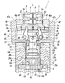
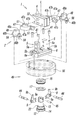
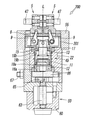
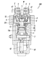
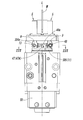
도 1~도 9에는, 본 발명에 따른 록 기구 부착 에어 척의 제 1 실시형태가 나타내어져 있다. 이 제 1 실시형태의 에어 척(100)은, 에어 실린더 장치(4)에 의해 한쌍의 핑거(5, 5)를 개폐시켜서 워크(W)의 파지 및 해방을 행하는 척 기구(1)와, 상기 한쌍의 핑거(5, 5)를 워크 파지 위치에 고정하는 록 기구(2)를, 네모난 블록형을 한 1개의 척 바디(3)에 상기 척 바디(3)의 중심을 지나는 축선(L)을 따라 일체로 장착한 것이다.1-9, the 1st Embodiment of the air chuck with a lock mechanism which concerns on this invention is shown. The
상기 척 기구(1)는, 도 1~도 6으로부터 분명하게 나타나 있는 바와 같이, 상기 에어 실린더 장치(4)와, 상기 한쌍의 핑거(5, 5)와, 상기 한쌍의 핑거(5, 5)를 개폐 가능하게 지지하는 지지 레일(8)과, 상기 에어 실린더 장치(4)의 로드(13)의 직선 동작을 상기 한쌍의 핑거(5, 5)의 개폐 동작으로 변환하는 한쌍의 개폐 레버(9, 9)를 갖는 것으로, 그 구체적 구성은 다음과 같다.As is apparent from FIGS. 1 to 6, the
상기 에어 실린더 장치(4)는, 일단(상단)이 개방되고 타단(하단)이 폐색된 원통형의 실린더 튜브(11)와, 상기 실린더 튜브(11)의 내부에 피스톤 패킹(14)을 통해서 축선(L) 방향으로 슬라이딩 가능하고 또한 상기 축선(L)을 중심으로 해서 상대적으로 회전 가능하도록 수용된 피스톤(12)과, 상기 피스톤(12)에 기단부를 연결하여 선단부가 상기 실린더 튜브(11)의 개방단으로부터 외부로 돌출하는 상기 로드(13)를 갖고 있다. 상기 실린더 튜브(11)의 개방단에는 링 형상을 한 로드 커버(15)가 기밀하게 고정되고, 상기 로드 커버(15)의 중심 구멍을 상기 로드(13)가, 로드 패킹(16)을 통해서 축선(L) 방향으로 슬라이딩 가능하고 또한 상기 축선(L)을 중심으로 상대적으로 회전 가능하도록 관통하고 있다.The
상기 피스톤 패킹(14)은 상기 피스톤(12)의 외주에 형성된 패킹 유지홈 내에 수용되고, 상기 로드 패킹(16)은 상기 로드 커버(15)의 내주에 형성된 패킹 유지홈 내에 수용되어 있다.The piston packing 14 is accommodated in a packing retaining groove formed in the outer circumference of the
또한, 상기 로드 커버(15)의 하단면에는 상기 로드 패킹(16)의 탈락이나 경사 등을 방지하기 위한 패킹 서포트(17)가 부착되고, 상기 피스톤(12)의 상단부에는 상기 피스톤(12)이 상기 로드 커버(15)의 패킹 서포트(17)에 접촉할 때의 충격을 완화하기 위한 댐퍼(22)가 부착되어 있다.In addition, a packing
상기 피스톤(12)과 상기 실린더 튜브(11)의 저벽(11a) 사이에는 제 1 압력실(18a)이 형성되고, 상기 피스톤(12)과 상기 로드 커버(15) 사이에는 제 2 압력실(18b)이 형성되고, 상기 실린더 튜브(11)의 측면에는 상기 제 1 압력실(18a)에 연통하는 제 1 통과 구멍(19a)과, 상기 제 2 압력실(18b)에 연통하는 제 2 통과 구멍(19b)이 형성되어 있다.A
또한, 상기 피스톤(12)의 상기 제 1 압력실(18a)측을 향하는 끝면에는, 상기 피스톤(12)의 동작 위치를 검출할 때의 피검체로 되는 링 형상의 마그넷(20)이 마그넷 홀더(21)를 통해서 부착되어 있다.Moreover, on the end surface of the said
상기 실린더 튜브(11)는 상기 척 바디(3)의 내부에 형성된 실린더 구멍(24)의 내부에 베어링(23)을 통해서 상기 축선(L)을 중심으로 일정한 각도 범위만 상대적으로 왕복 회전 가능하도록 수용되어 있다. 또한, 상기 실린더 튜브(11)의 외주와 상기 실린더 구멍(24)의 내주 사이에는 3개의 실린더 패킹(25a, 25b, 25c)이 설치되고, 이것들 3개의 실린더 패킹(25a, 25b, 25c) 사이에, 상기 제 1 통과 구멍(19a)에 연통하는 제 1 환상 유로(26a)와, 상기 제 2 통과 구멍(19b)에 연통하는 제 2 환상 유로(26b)가 상기 실린더 튜브(11)의 외주를 둘러싸도록 형성되고, 상기 척 바디(3)의 측면에는, 상기 제 1 환상 유로(26a)에 연통하는 제 1 포트(27a)와, 상기 제 2 환상 유로(26b)에 연통하는 제 2 포트(27b)가 형성되어 있다.The
따라서, 상기 제 1 포트(27a) 및 제 2 포트(27b)를, 도면에 나타내지 않은 전자 밸브에 의해 급기측과 배기측에 교대로 접속하면, 상기 제 1 환상 유로(26a) 및 제 2 환상 유로(26b)와, 상기 제 1 통과 구멍(19a) 및 제 2 통과 구멍(19b)을 통해서 상기 제 1 압력실(18a) 및 제 2 압력실(18b)에 압축 공기가 교대로 급배되기 때문에, 상기 피스톤(12) 및 로드(13)가 진퇴 이동(상하 이동)한다. 즉, 상기 제 1 포트(27a)를 압축 공기원에 접속함과 아울러 상기 제 2 포트(27b)를 대기에 개방하면, 상기 제 1 압력실(18a)에 압축 공기가 공급되기 때문에 피스톤(12) 및 로드(13)는 상승(도 7 참조)하고, 또한, 상기 제 2 포트(27b)를 압축 공기원에 접속함과 아울러 상기 제 1 포트(27a)를 대기에 개방하면, 상기 제 2 압력실(18b)에 압축 공기가 공급되기 때문에 피스톤(12) 및 로드(13)는 하강(도 2 참조)한다.Therefore, when the said
상기 핑거(5)는 측면으로 볼 때 형상이 L자형 또는 역T자형을 한 부재이고, 세로로 긴 파지부(5a)와, 상기 파지부(5a)의 기단부에 이어지는 가로로 긴 슬라이딩부(5b)를 갖고, 상기 파지부(5a)의 내측면에는 판 형상의 척 스페이서(6)가 나사(32)에 의해 부착되어, 서로 대향하는 척 스페이서(6, 6) 사이에 워크(W)를 파지하도록 구성되어 있다.The
상기 2개의 척 스페이서(6, 6)에는, 후술하는 제 1 록 부재(47, 47)가 1개씩 부착되어 있지만, 이 제 1 록 부재(47)의 구성에 대해서는 나중에 상세하게 설명한다.Although the
또한, 상기 지지 레일(8)은 좌우로 가늘고 긴 부재이며, 좌우로 연장되는 가이드홈(8a)을 상면에 갖고, 상기 가이드홈(8a) 내에 상기 핑거(5)의 슬라이딩부(5b)가 슬라이딩 가능하게 끼워맞추어져 있다. 상기 지지 레일(8)은 상기 척 바디(3)의 제 1 단(3a)측에 형성된 레일 홀더(37)에 고정적으로 부착되어 있다. 상기 레일 홀더(37)는 원통의 중앙 부분을 직경 방향으로 절제한 형태를 하고 있고, 원호 형상의 외주면을 갖는 한쌍의 부착벽(38, 38)과, 상기 한쌍의 부착벽(38, 38) 사이에 형성된 공간부(39)를 갖고 있다. 상기 한쌍의 부착벽(38, 38)의 대향면에는 나사 구멍(40a)을 갖는 단차부(40)가 형성되고, 상기 단차부(40) 상에 상기 지지 레일(8)을 적재하고, 상기 지지 레일(8)의 나사 삽입 통과 구멍에 레일 고정 나사(41)를 삽입 통과하여 상기 나사 구멍(40a)에 비틀어 넣음으로써, 상기 지지 레일(8)이 상기 한쌍의 부착벽(38, 38) 사이에 상기 공간부(39)를 덮도록 고정되어 있다.In addition, the
상기 레일 홀더(37)는 상기 척 바디(3)와 일체로 형성해도 좋지만, 상기 척 바디(3)와 별체로 형성하여, 나사로 상기 척 바디(3)에 부착해도 좋다.The
상기 개폐 레버(9, 9)는 L자형을 한 부재이며, 상기 지지 레일(8)로 덮여진 상기 공간부(39) 내에 수용되고, 각각의 개폐 레버(9)의 중간부가 레버 샤프트(44)에 의해 회전 가능하게 지지되어 있고, 상기 레버 샤프트(44)의 양단부는 상기 레일 홀더(37)의 한쌍의 부착벽(38, 38)에 형성된 지지 구멍(38a, 38a) 내에 끼워맞춤으로써 상기 레일 홀더(37)에 지지되어 있다. 또한, 상기 개폐 레버(9, 9)의 기단부에는 U자형을 한 절개(9a, 9a)가 형성되고, 이 절개(9a, 9a)가 상기 로드(13)의 선단의 맞물림 핀(45)에 맞물려 있고, 한편, 상기 개폐 레버(9, 9)의 선단부에는 원호 형상의 외면을 갖는 맞물림부(9b, 9b)가 형성되고, 이 맞물림부(9b, 9b)가 상기 핑거(5, 5)의 하면에 형성된 맞물림 오목부(5c, 5c) 내에 상기 지지 레일(8)에 형성된 개구(8b)를 통해서 요동 가능하게 끼워맞추어져 있다.The opening /
이 구성에 의해, 도 2~도 4에 나타내는 바와 같이, 상기 에어 실린더 장치(4)의 피스톤(12) 및 로드(13)가 하강하면, 상기 한쌍의 개폐 레버(9, 9)는 선단의 맞물림부(9b, 9b)가 서로 근접하는 방향으로 회전하기 때문에 상기 한쌍의 핑거(5, 5)는 닫히고, 도 7 및 도 8에 나타내는 바와 같이, 상기 피스톤(12) 및 로드(13)가 상승하면, 상기 한쌍의 개폐 레버(9, 9)는 선단의 맞물림부(9b, 9b)가 서로 멀어지는 방향으로 회전하기 때문에 상기 한쌍의 핑거(5, 5)는 열린다. 이러한 핑거(5, 5)의 개폐 동작에 의해, 상기 척 스페이서(6, 6) 사이에 워크(W)를 파지하거나, 파지한 워크(W)를 해방하거나 한다.By this structure, as shown in FIGS. 2-4, when the
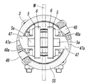
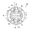
계속해서, 상기 록 기구(2)에 대하여 설명한다. 이 록 기구(2)는, 도 1~도 6으로부터 분명하게 나타나 있는 바와 같이, 상기 한쌍의 핑거(5, 5)에 설치된 한쌍의 상기 제 1 록 부재(47, 47)와, 상기 축선(L)을 중심으로 하는 원주 방향으로의 변위에 의해 상기 제 1 록 부재(47, 47)에 접촉/이간하는 한쌍의 제 2 록 부재(48, 48)와, 상기 제 2 록 부재(48, 48)를 상기 원주 방향으로 변위시키는 록 부재 변위 기구(49)와, 상기 록 부재 변위 기구(49)를 동작시키는 구동 장치(50)를 갖고 있다. 또, 이해하기 쉽게 하기 위해서, 도면에 있어서 상기 제 2 록 부재(48, 48)와, 상기 록 부재 변위 기구(49)를 구성하는 각 부품, 즉, 상기 제 2 록 부재(48, 48)와 일체로 되어서 변위(회전)하는 부품에는 도트가 붙여져 있다.Subsequently, the
상기 제 1 록 부재(47)는 상기 핑거(5)의 파지부(5a)가 끼워맞추어지는 오목부(47b)와, 상기 오목부(47b)의 양측에 형성된 부착부(47c)를 갖는 것으로, 상기 오목부(47b) 내에 상기 파지부(5a)를 끼워맞춘 상태에서 상기 부착부(47c)를 록 부재 고정 나사(51)로 상기 척 스페이서(6)에 고정함으로써 상기 한쌍의 핑거(5, 5)에 각각 부착되어 있고, 상기 한쌍의 핑거(5, 5)의 개폐와 함께 변위한다. 그리고, 상기 제 1 록 부재(47)의 외측면, 즉, 상기 제 2 록 부재(48)측을 향하는 면에는 상기 제 2 록 부재(48)의 변위 방향(원주 방향)을 향해서 상기 변위 방향과 교차하는 방향으로 경사지는 제 1 쐐기면(47a)이 형성되어 있다.The
한편, 상기 제 2 록 부재(48)는 네모난 블록형을 한 부재이며, 그 내측면, 즉, 상기 제 1 록 부재(47)측을 향하는 면에는 상기 제 1 록 부재(47)의 제 1 쐐기면(47a)과 같은 방향으로 경사지는 제 2 쐐기면(48a)이 형성되어 있다. 이들 제 2 쐐기면(48a) 및 제 1 쐐기면(47a)은 직선적으로 경사져 있어도 좋지만, 도시한 예에서는 모두 완만한 볼록 곡면 형상으로 경사져 있다.On the other hand, the
또한, 상기 제 2 록 부재(48)는 상기 척 바디(3)의 레일 홀더(37)의 주위 (따라서 한쌍의 핑거(5, 5)의 주위)에 설치된 링 형상의 지지 부재(55)의 상단에 부착부(48b)를 부착 나사(56)로 고정함으로써 부착되어 있다. 상기 지지 부재(55)는 상기 공간부(39)의 측면을 덮도록 설치되어 있고, 상기 척 기구(1)의 실린더 튜브(11)에 연결되고, 상기 실린더 튜브(11)에 의해 상기 축선(L)을 중심으로 해서 일정한 각도 범위를 왕복 회전시킬 수 있다. 상기 한쌍의 제 2 록 부재(48, 48)가 상기 지지 부재(55)에 부착되어 있는 위치는 상기 지지 부재(55)의 직경 방향의 서로 대향하는 위치이다.Further, the
따라서, 상기 제 1 록 부재(47)의 제 1 쐐기면(47a), 및, 상기 제 2 록 부재(48)의 제 2 쐐기면(48a)은 상기 지지 부재(55)의 원주와 교차하는 방향으로 경사져 있게 된다.Accordingly, the
상기 지지 부재(55)를 상기 실린더 튜브(11)에 연결하기 위해서, 상기 실린더 튜브(11)의 상단부에는 상기 실린더 튜브(11)의 직경 방향의 서로 대향하는 위치에 상기 축선(L)으로부터 멀어지는 방향으로 연장되는 한쌍의 지지 부재 부착부(57, 57)가 형성되어 있다. 상기 지지 부재 부착부(57)의 선단부는 상기 레일 홀더(37)에 형성된 요동용 절개부(39a)를 통해서 상기 레일 홀더(37)의 외측으로 돌출되어 있고, 상기 지지 부재 부착부(57)의 선단에 상기 지지 부재(55)가 지지 부재 고정 나사(58)로 고정되어 있다.In order to connect the
이 구성에 의해, 상기 실린더 튜브(11)를 일방향으로 회전시킴으로써 상기 지지 부재(55)를 축선(L)을 중심으로 소정의 각도 회전시켜, 도 4에 실선으로 나타내는 바와 같이, 상기 제 2 록 부재(48, 48)의 제 2 쐐기면(48a, 48a)을 상기 제 1 록 부재(47, 47)의 제 1 쐐기면(47a, 47a)에 쐐기 형상으로 접촉, 록킹시키면, 한쌍의 핑거(5, 5)는 그 위치에 록킹되어 개방할 수 없어진다. 이 때, 상기 제 1 쐐기면(47a)과 제 2 쐐기면(48a)이 접촉하는 것에 의한 쐐기 효과에 의해, 배력 작용이 일어나 록킹시의 유지력은 매우 커진다.By this structure, the said
또, 상기 실린더 튜브(11)의 회전시에, 상기 로드(13)는 그 선단이 맞물림 핀(45)으로 상기 한쌍의 개폐 레버(9, 9)에 실질적으로 연결된 상태에 있고, 이 개폐 레버(9, 9)가 회전하지 않기 때문에 상기 실린더 튜브(11)와 함께 회전할 일은 없다. 이 때 상기 실린더 튜브(11)와 함께 회전하는 것은, 상기 로드 커버(15), 로드 패킹(16), 및 패킹 서포트(17)이다.In addition, at the time of rotation of the
또한, 상기 실린더 튜브(11)를 역방향으로 회전시킴으로써 상기 지지 부재(55)를 역방향으로 회전시켜, 도 4에 쇄선으로 나타내는 바와 같이, 상기 제 2 록 부재(48, 48)를 상기 제 1 록 부재(47, 47)로부터 이간시키면, 한쌍의 핑거(5, 5)의 록은 해제되어 상기 핑거(5, 5)를 개방할 수 있게 된다.In addition, by rotating the
상기 실린더 튜브(11)는 상기 척 바디(3)의 하단인 제 2 단(3b)측에 나사(59)로 부착된 상기 구동 장치(50)에 연결되고, 이 구동 장치(50)에 의해 요동 회전된다.The
상기 구동 장치(50)는 베인형의 요동형 액츄에이터로 형성되어 있다. 이 요동형 액츄에이터는 제 1 바디 부분(60a) 및 제 2 바디 부분(60b)으로 이루어지는 액츄에이터 바디(60)와, 상기 액츄에이터 바디(60)의 내부에 형성된 베인실(61)과, 상기 베인실(61)의 내부에 일정한 각도 범위에서 요동 가능하도록 수용된 베인(62)과, 상기 축선(L) 상에 배치된 출력축(63)을 갖고, 상기 출력축(63)에 상기 베인(62)이 부착되어 있다. 또한, 상기 액츄에이터 바디(60)에는 상기 베인(62)의 양측의 압력실에 대하여 압축 공기를 공급 및 배출하는 제 3 포트(64a) 및 제 4 포트(64b)가 설치되어 있고, 상기 제 3 포트(64a) 및 제 4 포트(64b)를 통해서 상기압력실에 압축 공기를 급배함으로써 상기 베인(62)이 축선(L)을 중심으로 일정한 각도 범위를 왕복 회전하고, 그 회전력이 상기 출력축(63)을 통해서 인출된다.The
상기 출력축(63)은 상기 출력축(63)에 부착된 연계 부재(65)와, 상기 연계 부재(65)에 록킹하는 어저스트 부재(66)를 통해서 상기 실린더 튜브(11)에 연결되고, 상기 연계 부재(65) 및 어저스트 부재(66)를 통해서 상기 실린더 튜브(11)를 구동, 회전시킨다. 따라서, 상기 연계 부재(65) 및 어저스트 부재(66)와, 상기 실린더 튜브(11)와, 상기 지지 부재(55)는 상기 록 부재 변위 기구(49)를 구성하는 것이다.The
도면 중의 부호 69가 붙여진 부재는, 상기 어저스트 부재(66)를 실린더 튜브(11)의 저면에 연결하는 연결 나사, 마찬가지로 부호 59가 붙여진 부재는, 상기 액츄에이터 바디(60)의 제 2 바디 부분(60b)을 상기 척 바디(3)의 하단부에 부착하기 위한 부착 나사이다.In the drawing, a member denoted by 69 is a connecting screw for connecting the adjust
또한, 상기 어저스트 부재(66)는 상기 실린더 튜브(11)(따라서, 지지 부재(55) 및 제 2 록 부재(48))의 회전 각도의 설정 및 조정을 행하기 위한 부재이며, 2개의 스토퍼 레버(66a, 66a)를 갖고 있다. 이것에 대하여 상기 척 바디(3)에는, 2개의 어저스트 볼트(67, 67)가 진퇴 조작 가능하게 부착되어 있고, 상기 2개의 어저스트 볼트(67, 67)의 선단이 상기 2개의 스토퍼 레버(66a, 66a)에 개별적으로 대향하고 있다. 이것에 의해, 상기 실린더 튜브(11)는 상기 2개의 스토퍼 레버(66a, 66a)가 2개의 어저스트 볼트(67, 67)에 접촉하는 각도 범위 내에서 왕복 회전할 수 있고, 그 회전 각도는 상기 어저스트 볼트(67, 67)를 진퇴 조작함으로써 조정할 수 있다.In addition, the adjust
또한, 상기 척 바디(3)의 측면에는 자기 센서를 부착하기 위한 센서 부착홈(68)이 형성되어 있고, 상기 실린더 장치의 피스톤(12)에 부착된 마그넷(20)의 자기를 상기 자기 센서로 검출함으로써 상기 피스톤(12)의 동작 위치를 검출할 수 있다.In addition, a side surface of the
상기 구성을 갖는 에어 척(100)은, 예를 들면, 척 바디(3)를 자동 기계의 작업 암에 부착하여, 상기 한쌍의 핑거(5, 5)에 의해 워크(W)를 파지하고, 상기 워크(W)를 방향 전환하거나 다른 장소로 반송하거나 할 경우 등에 사용된다. 이 때, 상기 척 기구(1)의 에어 실린더 장치(4)와 록 기구(2)의 구동 장치(50)는 서로 별도의 공기압원에 접속된다. 상기 에어 척(100)에 의한 워크(W)의 파지 및 해방 동작은 다음과 같이 해서 행해진다.The
우선, 도 2 및 도 4에 나타내는 상태로부터, 상기 구동 장치(50)의 베인(62)을 압축 공기의 작용에 의해 도 4의 반시계 방향으로 회전시키고, 실린더 튜브(11)를 통해서 상기 지지 부재(55)를 같은 방향으로 회전시킴으로써, 상기 제 2 록 부재(48, 48)를 제 1 록 부재(47, 47)로부터 이간하는 쇄선 위치까지 변위시킨 뒤, 도 7 및 도 8에 나타내는 바와 같이, 상기 실린더 튜브(11)의 제 1 압력실(18a) 내에 압축 공기를 공급해서 상기 피스톤(12) 및 로드(13)를 상승시킴으로써 한쌍의 핑거(5, 5)를 개방시킨다.First, from the state shown in FIG. 2 and FIG. 4, the
다음으로, 도 8에 쇄선으로 나타내는 바와 같이, 파지해야 할 워크(W)를 상기 한쌍의 핑거(5, 5)의 척 스페이서(6, 6) 사이에 개재시키고, 그 상태에서, 상기 실린더 튜브(11)의 제 2 압력실(18b) 내에 압축 공기를 공급해서 상기 피스톤(12) 및 로드(13)를 하강시켜 상기 핑거(5, 5)를 폐쇄함으로써, 도 9에 나타내는 바와 같이, 상기 척 스페이서(6, 6) 사이에 워크(W)를 파지한다.Next, as shown by the broken line in FIG. 8, the workpiece W to be gripped is interposed between the
그 후, 상기 구동 장치(50)의 베인(62)을 압축 공기의 작용에 의해 회전시키고, 도 8의 위치에 있는 상기 지지 부재(55) 및 제 2 록 부재(48, 48)를 실린더 튜브(11)를 통해서 시계방향으로 회전시킴으로써, 도 9에 나타내는 바와 같이, 상기 제 2 록 부재(48, 48)의 제 2 쐐기면(48a, 48a)을 상기 제 1 록 부재(47, 47)의 제 1 쐐기면(47a, 47a)에 쐐기 형상으로 접촉시킨다. 그렇게 하면, 상기 한쌍의 핑거(5, 5)는 상기 제 2 록 부재(48, 48)에 의해 워크 파지 위치에 록킹되어 개방할 수 없게 된다.Thereafter, the
그렇게 해서 상기 핑거(5, 5)를 워크 파지 위치에 록킹한 상태에서, 상기 작업 암의 동작에 의해 상기 워크(W)의 방향을 바꾸거나 상기 워크(W)를 다른 장소로 반송하거나 하는 작업이 행해진다. 이 때, 어떠한 원인으로, 상기 척 기구(1) 즉 에어 실린더 장치(4)에 대한 압축 공기의 공급이 끊어졌다고 해도, 상기 한쌍의 핑거(5, 5)는 워크(W)를 파지한 상태를 그대로 유지하고, 파지력이 저하되지 않기 때문에, 상기 워크(W)의 위치 어긋남이나 낙하 등이 방지된다. 이 때문에, 상기 워크(W)가 낙하하는 것에 의한 상기 워크(W)의 파손이나 주변 기기의 파손 등이 방지되고, 작업자의 안전도 확보된다.In this state, the work of changing the direction of the work W or conveying the work W to another place by the operation of the work arm while the
상기 에어 척(100)이 파지하고 있는 워크(W)를 해방할 때는, 도 9의 상태로부터, 우선, 상기 구동 장치(50)에 의해 실린더 튜브(11)를 통해서 지지 부재(55)를 반시계 방향으로 회전시켜, 상기 제 2 록 부재(48, 48)를 제 1 록 부재(47, 47)로부터 이간하는 위치(도 8 참조)까지 변위시킴으로써 핑거(5, 5)의 록을 해제한다. 계속해서, 도 7 및 도 8에 나타내는 바와 같이, 에어 실린더 장치(4)의 로드(13)를 상승시켜서 상기 핑거(5, 5)를 개방함으로써 상기 워크(W)는 해방된다.When releasing the workpiece W held by the
상기 에어 척(100)은 상기 제 2 록 부재(48, 48)의 제 2 쐐기면(48a, 48a) 및 제 1 록 부재(47, 47)의 제 1 쐐기면(47a, 47a)이 각각 경사면을 하고 있기 때문에, 다른 두께의 워크(W)에도 대응할 수 있다. 이 경우, 도 9에 나타내는 워크(W)보다 두께가 두꺼운 워크(W)를 파지할 때는, 상기 제 2 록 부재(48)의 제 2 쐐기면(48a)과 제 1 록 부재(47)의 제 1 쐐기면(47a)이 맞물리는 정도는 도 9의 경우보다 작아지고, 그 반대로, 도 9에 나타내는 워크(W)보다 두께가 얇은 워크(W)를 파지할 때는, 상기 제 2 록 부재(48)의 제 2 쐐기면(48a)과 제 1 록 부재(47)의 제 1 쐐기면(47a)이 맞물리는 정도는 도 9의 경우보다 커진다.The
도 10~도 16에는, 본 발명에 따른 록 기구 부착 에어 척의 제 2 실시형태가 나타내어져 있다. 상술한 제 1 실시형태의 에어 척(100)에 있어서는, 상기 한쌍의 핑거(5, 5)를 워크 파지 위치에 록킹하기 위해서, 상기 제 1 록 부재(47, 47) 및 제 2 록 부재(48, 48) 중 제 2 록 부재(48, 48)를 회전시키도록 하고 있지만, 이 제 2 실시형태의 에어 척(200)에 있어서는, 상기 제 1 록 부재(47, 47)를 회전시키도록 하고 있다.10-16, 2nd Embodiment of the air chuck with lock mechanism which concerns on this invention is shown. In the
이 때문에, 상기 에어 척(200)에 있어서는, 도 10~도 12에 나타내는 바와 같이, 상기 제 1 록 부재(47, 47)가 부착되어 있는 핑거(5, 5)를 지지 레일(8)을 통해서 실린더 튜브(11)에 연결하고, 상기 실린더 튜브(11)로 상기 지지 레일(8) 및 핑거(5, 5)를 회전시킴으로써 상기 제 1 록 부재(47, 47)를 회전시키도록 하고 있고, 상기 제 2 록 부재(48, 48)가 부착되어 있는 지지 부재(55)는 척 바디(3)에 고정하고 있다.For this reason, in the said
또한, 상기 핑거(5, 5) 및 지지 레일(8)을 회전시킬 때, 개폐 레버(9, 9)와 로드(13) 및 피스톤(12)도 함께 회전할 수 있도록, 에어 실린더 장치(4)에 있어서는 상기 실린더 튜브(11)와 피스톤(12)에 회전 중지를 실시함으로써, 상기 실린더 튜브(11)와 피스톤(12)이 축선(L)을 중심으로 하는 회전 방향으로는 서로 일체화해서 상대적으로 회전하지 않지만, 축선(L) 방향으로는 상대적으로 변위 가능하도록 구성되어 있다.Further, when rotating the
이하, 제 2 실시형태의 상기 구성 및 작용에 대하여 설명하지만, 그 설명 중, 상기 제 1 실시형태와 공통되는 부품에는 상기 제 1 실시형태와 동일한 부호를 첨부하고, 상기 제 1 실시형태와 다른 구성에 새로운 부호를 첨부하는 것으로 한다.Hereinafter, although the said structure and operation | movement of 2nd Embodiment are demonstrated, in the description, the component which is common to the said 1st Embodiment is attached | subjected the same code | symbol as the said 1st Embodiment, and is a structure different from the said 1st Embodiment It is assumed that a new sign is attached to the.
또한, 이 제 2 실시형태의 도면에 있어서도, 이해하기 쉽게 하기 위해서, 상기 제 1 록 부재(47, 47)와 일체로 되어서 변위(회전)하는 부품에는 도트가 붙여져 있다.In addition, also in the figure of this 2nd Embodiment, in order to make it easy to understand, a dot is attached to the component which is integral with the said
상기 실린더 튜브(11)의 상단부에는 상기 실린더 튜브(11)보다 대경의 원통형을 한 레일 홀더(201)가 형성되어 있다. 상기 레일 홀더(201)의 상단부에는 상기 레일 홀더(201)의 직경 방향으로 연장되는 단차부(202)가 형성되고, 상기 단차부(202) 상에 상기 지지 레일(8)이 적재되고, 상기 지지 레일(8)의 나사 삽입 통과 구멍에 삽입 통과한 레일 고정 나사(41)를 상기 단차부(202)의 나사 구멍(204)에 비틀어 넣음으로써 상기 지지 레일(8)이 상기 실린더 튜브(11)에 고정되어 있다. 상기 단차부(202)의 폭 및 깊이는 상기 지지 레일(8)의 폭 및 높이와 거의 같은 정도이다.At the upper end of the
상기 레일 홀더(201)는 상기 실린더 튜브(11)와 일체로 형성되어 있지만, 상기 실린더 튜브(11)와 별체로 형성하고, 나사로 상기 실린더 튜브(11)에 부착해도 좋다.Although the said
또한, 척 바디(3)의 상단인 제 1 단(3a)에는 상기 지지 부재(55)의 내부에 끼워맞추는 링 형상의 끼워맞춤부(205)가 중앙에 형성됨과 아울러, 4개의 나사 구멍(206)이 네 모퉁이에 형성되어 있고, 상기 제 1 단(3a) 상에 상기 지지 부재(55)를 상기 끼워맞춤부(205)의 끼워맞춤에 의해 위치 결정된 상태로 적재하고, 상기 지지 부재(55)의 나사 삽입 통과 구멍에 삽입 통과한 고정 나사(207)를 상기 나사 구멍(206)에 나사 부착함으로써 상기 지지 부재(55)가 상기 척 바디(3)에 고정되어 있다.In addition, a ring-shaped
이 에어 척(200)에 있어서의 상기 이외의 구성은, 상기 제 1 실시형태의 에어 척(100)의 구성과 실질적으로 같기 때문에, 그 구성 중, 제 1 실시형태와 동일을 이루는 주요한 구성 부분에 상기 제 1 실시형태와 동일한 부호를 첨부해서 그 설명은 생략한다.Since the structure of that other than the above in this
상기 구성을 갖는 에어 척(200)에 있어서, 한쌍의 핑거(5, 5)로 워크를 파지할 때는, 도 10 및 도 11에 나타내는 바와 같이, 상기 실린더 튜브(11)를 구동 장치(50)에 의해 축선(L)을 중심으로 회전시킴으로써, 상기 핑거(5, 5)의 방향을 상기 제 1 록 부재(47, 47)가 제 2 록 부재(48, 48)에 대하여 비접촉으로 되는 위치를 차지하는 방향으로 한다. 이 때, 상기 실린더 튜브(11)와 함께, 상기 피스톤(12) 및 로드(13)와 개폐 레버(9)도 회전한다. 또, 도시한 예에서는, 상기 핑거(5, 5)의 방향을 상기 제 1 록 부재(47, 47)가 제 2 록 부재(48, 48)에 대하여 90도 다른 위치를 차지하는 방향으로 하고 있지만, 반드시 이러한 방향이 아니어도 상관 없다.In the
그리고, 상기 실린더 튜브(11)의 제 1 압력실(18a) 내에 압축 공기를 공급해서 상기 피스톤(12) 및 로드(13)를 상승시킴으로써, 도 13 및 도 14에 나타내는 바와 같이, 한쌍의 핑거(5, 5)를 개방시킨다.Then, by supplying compressed air into the
다음으로, 상기 한쌍의 핑거(5, 5)의 척 스페이서(6, 6) 사이에 워크(W)를 개재시킨 상태에서, 상기 실린더 튜브(11)의 제 2 압력실(18b) 내에 압축 공기를 공급해서 상기 피스톤(12) 및 로드(13)를 하강시켜, 상기 핑거(5, 5)를 폐쇄함으로써 상기 워크(W)를 파지한다.Next, compressed air is introduced into the
그 후, 도 15 및 도 16에 나타내는 바와 같이, 상기 구동 장치(50)에 의해 상기 실린더 튜브(11)를 축선(L)을 중심으로 회전시키고, 상기 제 1 록 부재(47, 47)의 제 1 쐐기면(47a, 47a)을 제 2 록 부재(48, 48)의 제 2 쐐기면(48a, 48a)에 쐐기 형상으로 접촉시킴으로써 상기 한쌍의 핑거(5, 5)는 워크 파지 위치에 록킹 된다.Then, as shown in FIG. 15 and FIG. 16, the said
상기 핑거(5, 5)가 파지한 워크(W)를 해방할 때는, 상기 워크(W)를 파지할 때의 상기 조작과는 역의 조작을 행하면 된다.When releasing the workpiece W held by the
제 2 실시형태의 에어 척(200)은 이와 같이 동작하기 때문에, 이 제 2 실시형태에 있어서 상기 제 1 록 부재(47, 47)를 변위시키기 위한 록 부재 변위 기구(49)는, 연계 부재(65) 및 어저스트 부재(66), 에어 실린더 장치(4), 개폐 레버(9, 9), 지지 레일(8), 핑거(5, 5), 및 척 스페이서(6, 6)에 의해 구성되어 있다고 할 수 있다.Since the
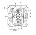
도 17~도 27에는 본 발명에 따른 록 기구 부착 에어 척의 제 3 실시형태가 나타내어져 있다. 이 제 3 실시형태의 에어 척(300)과 상기 제 1 실시형태의 에어 척(100)의 주요한 상위점은, 제 1 록 부재(47) 및 제 2 록 부재(48)의 형상 및 배치이다. 즉, 이 제 3 실시형태의 에어 척(300)에 있어서, 제 1 록 부재(47)는 샤프트 형상을 하고 있고, 한쌍의 핑거(5, 5)를 개폐시키는 로드(13)에 부착되어 있고, 상기 제 2 록 부재(48)는 상기 샤프트 형상의 제 1 록 부재(47)에 록킹 가능한 갈고리형을 하고 있고, 실린더 튜브(11)에 직접 부착되어 있다.17-27, 3rd embodiment of the air chuck with a lock mechanism which concerns on this invention is shown. The major difference between the
또한, 이것에 관련하여, 제 1 실시형태의 에어 척(100)에 있어서는 상기 제 2 록 부재(48)를 부착하기 위해서 필요한 링 형상의 지지 부재(55)가, 이 제 3 실시형태의 에어 척(300)에서는 생략되어 있고, 또한, 제 1 실시형태의 에어 척(100)에 있어서는 지지 레일(8)을 유지하는 레일 홀더(37)에 형성되어 있는 요동용 절개부(39a)가, 이 제 3 실시형태의 에어 척(300)의 레일 홀더(37)에는 형성되어 있지 않다.In addition, in this regard, in the
이하, 제 3 실시형태의 에어 척(300)의 구성 및 작용을 설명하지만, 그 때, 상기 제 1 실시형태의 에어 척(100)과 실질적으로 같은 구성을 갖는 주요한 부분 및 부품에 대해서는, 상기 제 1 실시형태와 동일한 부호를 첨부해서 그 구체적인 설명은 생략하고, 상기 제 1 실시형태와 다른 구성을 갖는 부분 및 부품에 대해서, 새로운 부호를 첨부해서 그 설명을 행하는 것으로 한다.Hereinafter, although the structure and operation | movement of the
또한, 이 제 3 실시형태의 도면에 있어서도, 이해하기 쉽게 하기 위해서, 상기 실린더 튜브(11)와 일체로 되어서 변위(회전)하는 부품에는 도트가 붙어 있다.In addition, also in the figure of this 3rd Embodiment, in order to make it easy to understand, the component which is integral with the said
도 18 및 도 19로부터 분명하게 나타내는 바와 같이, 상기 제 1 록 부재(47)는 로드(13)와 상기 한쌍의 개폐 레버(9, 9)를 연결하는 맞물림 핀(45)에 의해 형성되어 있다. 즉, 상기 제 1 록 부재(47)는 단면이 원형인 샤프트 형상을 하고 있고, 상기 축선(L)과 직교하는 방향으로 연장되어 상기 맞물림 핀(45)을 겸하고 있다. 또한, 상기 제 1 록 부재(47)의 길이는 상기 실린더 튜브(11)의 직경보다 길고, 상기 제 1 록 부재(47)의 양단은 상기 실린더 튜브(11)의 외주면보다 외측으로 돌출되어 있고, 이 돌출된 양단부에 상기 제 2 록 부재(48)가 고정되는 록킹부(47A)가 각각 형성되어 있다. 또한, 상기 제 1 록 부재(47)의 양단부는 상기 레일 홀더(37)의 내면에 형성된 가이드 홈(37a)(도 24 참조) 내에, 축선(L) 방향으로는 변위 가능하지만 축선(L)을 중심으로 하는 회전 방향으로는 고정적이도록 끼워맞추고 있다.As is apparent from FIGS. 18 and 19, the
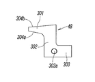
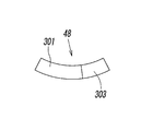
한편, 상기 제 2 록 부재(48)는, 도 20 및 도 21에 상세하게 나타내는 바와 같이, 측면에서 볼 때 대략 Z자형을 한 부재로서, 상기 록킹부(47A)에 록킹 및 이간하는 클로부(301)와, 상기 클로부(301)의 기단부로부터 하향(세로 방향)으로 연장되는 다리부(302)와, 상기 다리부(302)의 하단부로부터 가로 방향으로 가늘고 길게 신장되는 다리 저부(303)를 갖고, 전체가 상기 실린더 튜브(11)의 원주를 따른 형태로 만곡하고 있다.On the other hand, as shown in detail in Figs. 20 and 21, the
상기 클로부(301)는 상기 제 1 록 부재(47)와 교차하는 방향(가로 방향)으로 연장되고, 상하 양면에 쐐기면(304a, 304b)을 갖고 있고, 이 중, 하면에 형성된 하부 쐐기면(304a)은 상기 클로부(301)의 선단측을 향해서 점차로 상방, 즉 상부 쐐기면(304b)에 근접하는 방향으로 경사지고, 상면에 형성된 상부 쐐기면(304b)은 상기 클로부(301)의 선단측을 향해서 점차로 하방, 즉 상기 하부 쐐기면(304a)에 근접하는 방향으로 경사져 있다.The
상기 제 2 록 부재(48)는 실린더 튜브(11)의 상단부에 상기 제 1 록 부재(47)의 양단의 록킹부(47A, 47A)에 대응하도록 2개 부착되어 있다. 2개의 제 2 록 부재(48, 48)는 서로 동일 형상을 갖는 것으로, 상기 클로부(301)의 선단을 실린더 튜브(11)의 원주 방향을 향해서 서로 같은 방향으로 배치되어 있다. 이 제 2 록 부재(48)를 부착하기 위해서, 상기 실린더 튜브(11)의 상단부에는 플랜지 형상을 한 부착부(305)가 상기 실린더 튜브(11)의 직경 방향 외측으로 돌출하도록 형성되고, 상기 부착부(305)의 상면의 상기 축선(L)을 사이에 두고 서로 대향하는 위치에 상기 부착부(305)의 원주를 따라 만곡하는 긴 홈 형상을 한 2개의 부착홈(306)이 형성되고, 상기 부착홈(306)의 내부에 상기 다리 저부(303)를 끼워맞추고, 고정 핀(307)을 상기 부착부(305)의 측면 방향으로부터 상기 부착부(305) 및 상기 다리 저부(303)에 형성된 고정 구멍(303a)에 삽입함으로써 상기 제 2 록 부재(48)가 상기 실린더 튜브(11)에 고정되어 있다.The
상기 제 3 실시형태의 에어 척(300)이 상술한 점 이외로 제 1 실시형태의 에어 척(100)과 다른 점은, 레일 홀더(37)가 척 바디(3)의 제 1 단(3a)에 홀더 고정 나사(310)로 고정되어 있는 것, 및, 핑거(5, 5)를 지지하는 지지 레일(8)을 상기 레일 홀더(37)의 단차부(40)에 레일 고정 나사(41)로 고정할 경우에, 상기 레일 홀더(37)의 측면의 나사 구멍(308)에 위치 결정 나사(309)를 부착하고, 상기 위치 결정 나사(309)로 상기 지지 레일(8)을 상기 단차부(40)의 반대측의 측벽(40b)에 압박함으로써 상기 지지 레일(8)을 정확하게 위치 결정한 상태에서 고정되어 있는 것이다.The
또, 다른 상이점은, 척 바디에 어저스트 볼트(67)를 1개 부착하고, 이 1개의 어저스트 볼트(67)로 어저스트 부재(66)의 회전 각도 범위를 조정함으로써 상기 제 2 록 부재(48)의 록 해제 위치를 조정하도록 하고 있는 것이다.Another difference is that the second lock member (by attaching one adjust
이 에어 척(300)에 있어서의 상기 이외의 구성은, 상기 제 1 실시형태의 에어 척(100)의 구성과 실질적으로 같다.The configuration other than the above in the
또, 제 3 실시형태의 에어 척(300)에 있어서의 상기 위치 결정 나사(309) 및 1개의 어저스트 볼트(67)에 관한 구성은, 제 1 실시형태의 에어 척(100) 및 제 2 실시형태의 에어 척(200)에도 적용할 수 있다.Moreover, the structure regarding the said
다음으로, 상기 에어 척(300)의 작용에 대하여 설명하는 도 22는 한쌍의 핑거(5, 5)가 개방함으로써 워크(W)를 파지하지 않은 상태를 나타내고 있다. 이 때, 제 1 록 부재(47)는 로드(13)가 전진(상승)함으로써 상승 위치를 차지하고 있고, 제 2 록 부재(48)는 상기 제 1 록 부재(47)로부터 이간한 언록 위치를 차지하고 있다.Next, FIG. 22 which demonstrates the operation | movement of the said
이 상태로부터, 상기 한쌍의 핑거(5, 5)로 워크(W)를 파지할 때는, 도 23 및 도 24에 나타내는 바와 같이, 에어 실린더 장치(4)(도 18 참조)로 상기 로드(13)를 후퇴(하강)시킴으로써 상기 한쌍의 핑거(5, 5)를 닫도록 한다. 이 때, 상기 제 1 록 부재(47)도 로드(13)와 함께 하강한다.From this state, when holding the workpiece | work W with the said pair of
그 후, 도 25 및 도 26에 나타내는 바와 같이, 상기 구동 장치(50)로 상기 실린더 튜브(11)를 축선(L)을 중심으로 시계방향으로 회전시켜서 2개의 제 2 록 부재(48, 48)를 록 위치로 변위시키고, 상기 제 2 록 부재(48, 48)의 하부 쐐기면(304a)을 제 1 록 부재(47)의 양단의 록킹부(47A)의 상면에 록킹시킴으로써, 상기 한쌍의 핑거(5, 5)는 워크 파지 위치에 록킹된다.Then, as shown in FIG.25 and FIG.26, the said
상기 핑거(5, 5)가 파지한 워크(W)를 해방할 때는, 상기 워크(W)를 파지할 때의 조작과는 역의 조작을 행하면 된다.When releasing the workpiece | work W hold | gripped by the said
상기 에어 척(300)은, 도 27에 나타내는 바와 같이, 중심 구멍(H)을 갖는 워크(W)의 내경을 척할 수도 있다. 이 내경 척은 상기 에어 실린더 장치(4)로 로드(13)를 하강시켜서 한쌍의 핑거(5, 5)를 닫은 상태로 하고, 그 상태에서 상기 핑거(5, 5)를 상기 워크(W)의 중심 구멍(H) 내에 삽입한 뒤, 상기 로드(13)를 상승시켜서 상기 한쌍의 핑거(5, 5)를 개방시키고, 상기 핑거(5, 5)의 외측면을 상기 중심 구멍(H)의 내주에 록킹시킴으로써 행해진다. 이 때, 상기 제 2 록 부재(48, 48)는, 도 27에 쇄선으로 나타내는 바와 같이, 상기 제 1 록 부재(47)로부터 이간한 언록 위치를 차지하고 있다. As shown in FIG. 27, the
상기 워크(W)의 내경을 척한 뒤, 구동 장치(50)로 상기 실린더 튜브(11)를 회전시키고, 상기 제 2 록 부재(48, 48)를 도 27에 실선으로 나타내는 바와 같이 록 위치로 변위시킴으로써, 상기 제 2 록 부재(48, 48)의 상부 쐐기면(304b)이 제 1 록 부재(47)의 양단의 록킹부(47A, 47A)의 하면에 록킹되기 때문에, 상기 한쌍의 핑거(5, 5)는 워크 파지 위치에 록킹된다.After chucking the inner diameter of the workpiece W, the
또, 워크(W)의 내경을 척할 때는 상기 핑거(5, 5)에 척 스페이서(6)를 부착하지 않아도 좋다.In addition, when chucking the inner diameter of the workpiece | work W, it is not necessary to attach the
또한, 도시한 실시형태에서는 상기 제 1 록 부재(47)가 상기 맞물림 핀(45)과 겸용되어 있지만, 상기 제 1 록 부재(47)는 상기 맞물림 핀(45)과 별도로 설치해도 좋다.In addition, although the said
상기 제 3 실시형태의 에어 척(300)에서는, 상기 제 1 록 부재(47)를 비회전으로 하고, 상기 제 2 록 부재(48, 48)를 실린더 튜브(11)를 통해서 구동 장치(50)로 회전시키도록 하고 있지만, 그 반대로, 상기 제 2 록 부재(48, 48)를 비회전으로 하고, 상기 제 1 록 부재(47)를 실린더 튜브(11)를 통해서 구동 장치(50)로 회전시키도록 구성할 수도 있다. 이 경우, 제 2 실시형태의 에어 척(200)과 마찬가지로, 상기 제 2 록 부재(48, 48)를 적당한 지지 부재를 통해서 척 바디(3)에 고정하고, 상기 피스톤(12), 로드(13), 제 1 록 부재(47), 개폐 레버(9, 9), 지지 레일(8), 핑거(5, 5) 등을, 상기 실린더 튜브(11)와 함께 회전하도록 구성하면 좋다.In the
1 : 척 기구 2 : 록 기구
3 : 척 바디 5 : 핑거
8 : 지지 레일 11 : 실린더 튜브
12 : 피스톤 13 : 로드
18a : 제 1 압력실 18b : 제 2 압력실
19a : 제 1 통과 구멍 19b : 제 2 통과 구멍
24 : 실린더 구멍 26a : 제 1 환상 유로
26b : 제 2 환상 유로 27a : 제 1 포트
27b : 제 2 포트 47 : 제 1 록 부재
47a : 제 1 쐐기면 48 : 제 2 록 부재
48a : 제 2 쐐기면 50 : 구동 장치
55 : 지지 부재 63 : 출력축
100, 200, 300 : 에어 척 W : 워크
L : 축선1: Chuck Mechanism 2: Lock Mechanism
3: chuck body 5: finger
8: support rail 11: cylinder tube
12
18a:
19a: first through
24:
26b: second
27b: 2nd port 47: 1st lock member
47a: 1st wedge surface 48: 2nd lock member
48a: second wedge surface 50: drive device
55
100, 200, 300: Air Chuck W: Walk
L: axis
Claims (9)
상기 록 기구는 상기 한쌍의 핑거의 개폐와 함께 변위하는 제 1 록 부재와, 상기 제 1 록 부재에 록킹함으로써 상기 한쌍의 핑거를 워크 파지 위치에 록킹하는 제 2 록 부재와, 상기 제 1 록 부재와 제 2 록 부재를 서로 고정하는 록 위치와 서로 이간하는 언록 위치로 상대적으로 변위시키는 구동 장치를 갖고,
상기 제 1 록 부재 및 제 2 록 부재는, 상기 로드의 축선을 중심으로 하는 상대적인 회전에 의해 상기 록 위치와 언록 위치로 변위하는 것을 특징으로 하는 록 기구 부착 에어 척.A chuck mechanism for operating the piston inside the cylinder tube by the action of compressed air and opening and closing a pair of fingers by moving the rod connected to the piston to hold the workpiece, and fixing the pair of fingers at the work holding position. With a lock mechanism
The lock mechanism includes a first lock member that is displaced with the opening and closing of the pair of fingers, a second lock member that locks the pair of fingers to a work holding position by locking the first lock member, and the first lock member. And a drive device for relatively displacing the first lock member and the second lock member into a locked position spaced apart from each other,
And the first lock member and the second lock member are displaced to the locked position and the unlocked position by relative rotation about the axis of the rod.
상기 실린더 튜브는 척 바디의 실린더 구멍 내에 축선을 중심으로 일정한 각도 범위를 왕복 회전 가능하도록 수용됨과 아울러 상기 구동 장치에 연결되고, 상기 제 1 록 부재 및 제 2 록 부재의 어느 한쪽이, 상기 구동 장치에 의해 상기 실린더 튜브를 통해서 상기 록 위치와 언록 위치로 구동되도록 구성된 것을 특징으로 하는 에어 척.The method of claim 1,
The cylinder tube is accommodated in the cylinder hole of the chuck body so as to reciprocally rotate a predetermined angle range about an axis and is connected to the drive device, wherein either one of the first lock member and the second lock member is connected to the drive device. And is driven to the locked position and the unlocked position through the cylinder tube.
상기 실린더 튜브의 외주와 상기 실린더 구멍의 내주 사이에는, 상기 척 바디에 형성된 제 1 포트에 연통하는 제 1 환상 유로와, 상기 척 바디에 형성된 제 2 포트에 연통하는 제 2 환상 유로가 상기 실린더 튜브의 외주를 둘러싸도록 형성되고,
상기 실린더 튜브의 측면에는, 상기 피스톤의 일측의 제 1 압력실과 상기 제 1 환상 유로를 연결하는 제 1 통과 구멍과, 상기 피스톤의 타측의 제 2 압력실과 상기 제 2 환상 유로를 연결하는 제 2 통과 구멍이 형성되어 있는 것을 특징으로 하는 에어 척.The method of claim 2,
Between the outer circumference of the cylinder tube and the inner circumference of the cylinder bore, a first annular flow passage communicating with the first port formed in the chuck body and a second annular flow passage communicating with the second port formed in the chuck body are located in the cylinder tube. Is formed to surround the outer periphery of,
On the side surface of the cylinder tube, a first passage hole connecting the first pressure chamber on one side of the piston and the first annular flow passage, and a second passage connecting the second pressure chamber on the other side of the piston and the second annular flow passage. Air chuck, characterized in that the hole is formed.
상기 구동 장치는 요동형 액츄에이터에 의해 형성되고, 상기 요동형 액츄에이터는 압축 공기의 작용에 의해 일정한 각도 범위를 왕복 회전하는 출력축을 갖고, 상기 출력축이 상기 실린더 튜브에 연결되어 있는 것을 특징으로 하는 에어 척.The method of claim 2,
The drive device is formed by a rocking actuator, the rocking actuator has an output shaft for reciprocating rotation in a predetermined angular range by the action of compressed air, the output shaft is connected to the cylinder tube, characterized in that .
상기 한쌍의 핑거는 지지 레일에 개폐 가능하게 지지되고, 상기 제 1 록 부재는 상기 한쌍의 핑거에 각각 부착되며, 상기 제 2 록 부재는 상기 지지 레일의 주위에 설치된 지지 부재에 2개 부착되어 있고,
상기 지지 레일 및 지지 부재의 어느 한쪽이 상기 실린더 튜브에 연결되어 있고, 상기 실린더 튜브로 상기 지지 레일 또는 지지 부재를 왕복 회전시킴으로써, 상기 제 1 록 부재 및 제 2 록 부재가 서로 록킹 및 이간하는 위치로 상대적으로 변위하도록 구성된 것을 특징으로 하는 에어 척.The method of claim 2,
The pair of fingers are supported to open and close to the support rail, the first lock member is attached to the pair of fingers, respectively, and the second lock member is attached to two support members installed around the support rail, ,
One of the support rail and the support member is connected to the cylinder tube, and the first lock member and the second lock member are locked and separated from each other by reciprocally rotating the support rail or the support member with the cylinder tube. Air chuck, characterized in that configured to displace relatively.
상기 제 1 록 부재 및 제 2 록 부재는 서로 록킹하는 쐐기면을 갖고, 상기쐐기면은 상기 제 1 록 부재 또는 제 2 록 부재의 변위 방향인 원주 방향을 향해서, 상기 원주 방향과 교차하는 방향으로 경사져 있는 것을 특징으로 하는 에어 척.The method of claim 5, wherein
The first lock member and the second lock member have a wedge surface that locks each other, the wedge surface in a direction intersecting the circumferential direction toward a circumferential direction that is a displacement direction of the first lock member or the second lock member. Air chuck characterized in that the inclined.
상기 지지 부재는 링 형상을 이루고 있고, 상기 지지 레일의 외주를 둘러싸도록 배치되고, 상기 지지 부재의 직경 방향의 서로 대향하는 위치에 상기 제 2 록 부재가 부착되어 있는 것을 특징으로 하는 에어 척.The method of claim 5, wherein
The support member has a ring shape, is disposed to surround the outer circumference of the support rail, and the second lock member is attached to a position opposite to each other in the radial direction of the support member.
상기 제 1 록 부재는 상기 로드에 축선과 직교하는 방향에 설치된 샤프트 형상의 부재로 이루어지고, 상기 제 2 록 부재는 상기 제 1 록 부재에 록킹 가능한 갈고리형의 부재로 이루어지는 것을 특징으로 하는 에어 척.The method of claim 2,
The first lock member is made of a shaft-shaped member provided in a direction orthogonal to an axis on the rod, and the second lock member is made of a hook-shaped member which is lockable to the first lock member. .
상기 로드와 제 1 록 부재는 상기 실린더 튜브가 회전해도 상기 실린더 튜브와 함께 회전하지 않도록 배치되고, 상기 제 2 록 부재는 상기 실린더 튜브에 상기 실린더 튜브와 함께 회전하도록 연결되어 있는 것을 특징으로 하는 에어 척.The method of claim 8,
The rod and the first lock member are arranged not to rotate together with the cylinder tube even when the cylinder tube rotates, and the second lock member is connected to the cylinder tube so as to rotate together with the cylinder tube. chuck.
Applications Claiming Priority (5)
| Application Number | Priority Date | Filing Date | Title |
|---|---|---|---|
| JPJP-P-2017-098339 | 2017-05-17 | ||
| JP2017098339 | 2017-05-17 | ||
| JP2017165513 | 2017-08-30 | ||
| JPJP-P-2017-165513 | 2017-08-30 | ||
| PCT/JP2018/006098 WO2018211763A1 (en) | 2017-05-17 | 2018-02-21 | Air chuck provided with locking mechanism |
Publications (2)
| Publication Number | Publication Date |
|---|---|
| KR20200007786A true KR20200007786A (en) | 2020-01-22 |
| KR102414982B1 KR102414982B1 (en) | 2022-06-30 |
Family
ID=64273715
Family Applications (1)
| Application Number | Title | Priority Date | Filing Date |
|---|---|---|---|
| KR1020197031573A KR102414982B1 (en) | 2017-05-17 | 2018-02-21 | Air chuck with lock mechanism |
Country Status (10)
| Country | Link |
|---|---|
| US (1) | US10953477B2 (en) |
| JP (1) | JP7020619B2 (en) |
| KR (1) | KR102414982B1 (en) |
| CN (1) | CN110621454B (en) |
| BR (1) | BR112019023915A2 (en) |
| DE (1) | DE112018002553T5 (en) |
| MX (1) | MX2019013591A (en) |
| RU (1) | RU2751612C2 (en) |
| TW (1) | TWI744492B (en) |
| WO (1) | WO2018211763A1 (en) |
Families Citing this family (6)
| Publication number | Priority date | Publication date | Assignee | Title |
|---|---|---|---|---|
| JP6953336B2 (en) * | 2018-03-22 | 2021-10-27 | 本田技研工業株式会社 | Connector |
| TWI734454B (en) * | 2020-04-28 | 2021-07-21 | 鴻海精密工業股份有限公司 | Identity recognition device and identity recognition method |
| CN111975810B (en) * | 2020-09-11 | 2021-12-14 | 鹤壁职业技术学院 | Mechanical finger and mechanical arm |
| JP2022162616A (en) * | 2021-04-13 | 2022-10-25 | Smc株式会社 | air chuck |
| RU208230U1 (en) * | 2021-07-07 | 2021-12-08 | Федеральное государственное бюджетное образовательное учреждение высшего образования "Кубанский государственный аграрный университет им. И.Т. Трубилина" | Machine vice |
| CN113696211B (en) * | 2021-09-13 | 2023-12-01 | 北京理工大学 | Soft tongs of space arm |
Citations (6)
| Publication number | Priority date | Publication date | Assignee | Title |
|---|---|---|---|---|
| JPH07100785A (en) | 1993-10-05 | 1995-04-18 | Ckd Corp | Air chuck having switch |
| JPH10166290A (en) | 1997-06-30 | 1998-06-23 | Ckd Corp | Air chuck with switch |
| KR20010050582A (en) * | 1999-10-12 | 2001-06-15 | 다까다 요시유끼 | Electric hand with cushioning mechanism |
| KR20050078977A (en) * | 2004-02-03 | 2005-08-08 | 에스엠시 가부시키가이샤 | Air pressure driving chuck having gripping member with variable stroke |
| JP2009214204A (en) * | 2008-03-07 | 2009-09-24 | Ckd Corp | Robot hand |
| JP2010069570A (en) | 2008-09-18 | 2010-04-02 | Denso Corp | Air chuck device |
Family Cites Families (17)
| Publication number | Priority date | Publication date | Assignee | Title |
|---|---|---|---|---|
| JPS5347732Y2 (en) | 1973-04-06 | 1978-11-15 | ||
| US4530508A (en) * | 1982-07-14 | 1985-07-23 | Ferraro Thomas A | Jaw locking means for lathe chucks |
| EP0208827B1 (en) * | 1984-08-04 | 1990-06-06 | Robert Bosch Gmbh | Gripper |
| JPH0616685Y2 (en) | 1990-04-20 | 1994-05-02 | 有限会社エリー工業 | Parts gripper for parts handling equipment |
| RU2096167C1 (en) * | 1996-05-28 | 1997-11-20 | Московское авиационное производственное объединение "МИГ" | Gripping device for robot |
| US6588816B1 (en) * | 1996-10-07 | 2003-07-08 | Phd, Inc. | Modular stamped parts transfer gripper |
| JP4126333B2 (en) | 1997-02-12 | 2008-07-30 | Smc株式会社 | Linear guide type air chuck |
| JP3263373B2 (en) * | 1998-12-18 | 2002-03-04 | エービービー株式会社 | Automatic coating equipment |
| JP2000343473A (en) * | 1999-06-03 | 2000-12-12 | Smc Corp | Parallel opening/closing chuck |
| RU32423U1 (en) * | 2003-05-19 | 2003-09-20 | Московский государственный открытый университет | Industrial robot grab |
| JP2008272867A (en) | 2007-04-27 | 2008-11-13 | Kondo Seisakusho:Kk | Parallel hands with lock mechanism |
| JP4737456B2 (en) * | 2007-11-22 | 2011-08-03 | Smc株式会社 | Gripper mechanism |
| WO2012073723A1 (en) * | 2010-12-02 | 2012-06-07 | 株式会社コスメック | Clamp apparatus |
| DE102011115366A1 (en) | 2011-10-10 | 2013-04-11 | Günther Zimmer | Gripping device with holding device |
| CN203804634U (en) * | 2014-04-19 | 2014-09-03 | 建湖县海盛机械制造有限公司 | Wedge-push-type two-way spindle chuck of double-head lathe |
| JP6227578B2 (en) | 2015-02-25 | 2017-11-08 | Ckd株式会社 | Gripping device |
| JP6628076B2 (en) * | 2015-06-30 | 2020-01-08 | Smc株式会社 | Chuck device |
-
2018
- 2018-02-21 CN CN201880032184.6A patent/CN110621454B/en active Active
- 2018-02-21 JP JP2019519064A patent/JP7020619B2/en active Active
- 2018-02-21 KR KR1020197031573A patent/KR102414982B1/en active IP Right Grant
- 2018-02-21 MX MX2019013591A patent/MX2019013591A/en unknown
- 2018-02-21 BR BR112019023915-4A patent/BR112019023915A2/en not_active IP Right Cessation
- 2018-02-21 US US16/613,340 patent/US10953477B2/en active Active
- 2018-02-21 WO PCT/JP2018/006098 patent/WO2018211763A1/en active Application Filing
- 2018-02-21 DE DE112018002553.5T patent/DE112018002553T5/en active Pending
- 2018-02-21 RU RU2019141618A patent/RU2751612C2/en active
- 2018-02-27 TW TW107106504A patent/TWI744492B/en active
Patent Citations (6)
| Publication number | Priority date | Publication date | Assignee | Title |
|---|---|---|---|---|
| JPH07100785A (en) | 1993-10-05 | 1995-04-18 | Ckd Corp | Air chuck having switch |
| JPH10166290A (en) | 1997-06-30 | 1998-06-23 | Ckd Corp | Air chuck with switch |
| KR20010050582A (en) * | 1999-10-12 | 2001-06-15 | 다까다 요시유끼 | Electric hand with cushioning mechanism |
| KR20050078977A (en) * | 2004-02-03 | 2005-08-08 | 에스엠시 가부시키가이샤 | Air pressure driving chuck having gripping member with variable stroke |
| JP2009214204A (en) * | 2008-03-07 | 2009-09-24 | Ckd Corp | Robot hand |
| JP2010069570A (en) | 2008-09-18 | 2010-04-02 | Denso Corp | Air chuck device |
Also Published As
| Publication number | Publication date |
|---|---|
| KR102414982B1 (en) | 2022-06-30 |
| RU2019141618A (en) | 2021-06-17 |
| JPWO2018211763A1 (en) | 2020-03-19 |
| BR112019023915A2 (en) | 2020-06-02 |
| TW201900364A (en) | 2019-01-01 |
| JP7020619B2 (en) | 2022-02-16 |
| DE112018002553T5 (en) | 2020-01-30 |
| MX2019013591A (en) | 2020-01-13 |
| US10953477B2 (en) | 2021-03-23 |
| US20200130069A1 (en) | 2020-04-30 |
| CN110621454B (en) | 2023-05-16 |
| RU2019141618A3 (en) | 2021-06-17 |
| CN110621454A (en) | 2019-12-27 |
| WO2018211763A1 (en) | 2018-11-22 |
| RU2751612C2 (en) | 2021-07-15 |
| TWI744492B (en) | 2021-11-01 |
Similar Documents
| Publication | Publication Date | Title |
|---|---|---|
| KR20200007786A (en) | Air Chuck with Lock Mechanism | |
| KR101643374B1 (en) | Clamp apparatus | |
| KR100918497B1 (en) | Chuck apparatus | |
| JP4122490B2 (en) | Combined type air chuck with position detection mechanism | |
| US4594033A (en) | Boring tool for producing undercuts in holes | |
| EP1624201A2 (en) | Hook pin unit having weld slag protection | |
| JP3760429B2 (en) | 2-drive fluid pressure chuck | |
| US6491304B2 (en) | Cylinder having guide | |
| US20180207783A1 (en) | Portable Power Tool | |
| US6915868B1 (en) | Elevator apparatus and method for running well bore tubing | |
| JP5201619B2 (en) | Automatic tool changer lock mechanism | |
| US20120325498A1 (en) | Floating spider | |
| RU2558022C2 (en) | Tool for installation of valve cotters in engine valve | |
| JP2008272867A (en) | Parallel hands with lock mechanism | |
| US20040041322A1 (en) | Swing clamp | |
| US11572746B2 (en) | Rotary gripping apparatus for a power tong | |
| CN209924943U (en) | Centering and clamping device for automatic connection and buckling of drill rod | |
| FI81885B (en) | GRIPSAXANORDNING FOER GRIPNING OCH ROTERING. SIIRRETTY ALKUPAEIVAE-FOERSKJUTET DATUM PL 14 ç 19.10.87. | |
| CN107377795B (en) | Edge turning machine head | |
| CN102478030A (en) | Hydraulic automatic control reversing valve | |
| KR100563613B1 (en) | air chuck having a stroke adjuster | |
| WO2010140554A1 (en) | Clamp device | |
| CN115161599B (en) | Vacuum cavity opening structure and method | |
| AU2005231223A1 (en) | Clamping apparatus, drill string component and rock drilling rig | |
| KR200287087Y1 (en) | Turning work party for milring work |
Legal Events
| Date | Code | Title | Description |
|---|---|---|---|
| E701 | Decision to grant or registration of patent right | ||
| GRNT | Written decision to grant |