KR20200003385A - Acoustic Calibration Arrays for Tanks and Vessels - Google Patents
Acoustic Calibration Arrays for Tanks and Vessels Download PDFInfo
- Publication number
- KR20200003385A KR20200003385A KR1020197033638A KR20197033638A KR20200003385A KR 20200003385 A KR20200003385 A KR 20200003385A KR 1020197033638 A KR1020197033638 A KR 1020197033638A KR 20197033638 A KR20197033638 A KR 20197033638A KR 20200003385 A KR20200003385 A KR 20200003385A
- Authority
- KR
- South Korea
- Prior art keywords
- transducer
- acoustic
- sensors
- tof
- volume
- Prior art date
Links
- 238000003491 array Methods 0.000 title 1
- 238000000034 method Methods 0.000 claims abstract description 60
- 238000005259 measurement Methods 0.000 claims abstract description 40
- 238000004891 communication Methods 0.000 claims description 19
- 238000001514 detection method Methods 0.000 claims description 19
- 238000004458 analytical method Methods 0.000 claims description 18
- 238000000926 separation method Methods 0.000 claims description 8
- 230000001902 propagating effect Effects 0.000 claims description 5
- 238000002366 time-of-flight method Methods 0.000 claims description 5
- 238000012544 monitoring process Methods 0.000 claims description 4
- 239000008280 blood Substances 0.000 claims 1
- 210000004369 blood Anatomy 0.000 claims 1
- 238000007689 inspection Methods 0.000 abstract description 3
- 239000000463 material Substances 0.000 description 15
- 238000012937 correction Methods 0.000 description 11
- 238000010586 diagram Methods 0.000 description 10
- 230000008569 process Effects 0.000 description 9
- 230000006870 function Effects 0.000 description 8
- 238000004364 calculation method Methods 0.000 description 6
- 238000004590 computer program Methods 0.000 description 5
- 238000012360 testing method Methods 0.000 description 5
- 230000008859 change Effects 0.000 description 4
- 239000003921 oil Substances 0.000 description 4
- 230000003287 optical effect Effects 0.000 description 4
- 238000012545 processing Methods 0.000 description 4
- 230000014509 gene expression Effects 0.000 description 3
- 239000002184 metal Substances 0.000 description 3
- 229910052751 metal Inorganic materials 0.000 description 3
- 230000001066 destructive effect Effects 0.000 description 2
- 229930195733 hydrocarbon Natural products 0.000 description 2
- 150000002430 hydrocarbons Chemical class 0.000 description 2
- 230000007774 longterm Effects 0.000 description 2
- 239000000047 product Substances 0.000 description 2
- 238000013515 script Methods 0.000 description 2
- GPAAEXYTRXIWHR-UHFFFAOYSA-N (1-methylpiperidin-1-ium-1-yl)methanesulfonate Chemical compound [O-]S(=O)(=O)C[N+]1(C)CCCCC1 GPAAEXYTRXIWHR-UHFFFAOYSA-N 0.000 description 1
- 229910000831 Steel Inorganic materials 0.000 description 1
- 230000005856 abnormality Effects 0.000 description 1
- 230000032683 aging Effects 0.000 description 1
- 239000000956 alloy Substances 0.000 description 1
- 229910045601 alloy Inorganic materials 0.000 description 1
- 238000013459 approach Methods 0.000 description 1
- 230000015556 catabolic process Effects 0.000 description 1
- 230000001413 cellular effect Effects 0.000 description 1
- 239000002131 composite material Substances 0.000 description 1
- 230000007797 corrosion Effects 0.000 description 1
- 238000005260 corrosion Methods 0.000 description 1
- 239000010779 crude oil Substances 0.000 description 1
- 238000013500 data storage Methods 0.000 description 1
- 238000006731 degradation reaction Methods 0.000 description 1
- 230000001419 dependent effect Effects 0.000 description 1
- 230000004069 differentiation Effects 0.000 description 1
- 238000005516 engineering process Methods 0.000 description 1
- 230000003203 everyday effect Effects 0.000 description 1
- 230000002706 hydrostatic effect Effects 0.000 description 1
- 238000009434 installation Methods 0.000 description 1
- 239000007788 liquid Substances 0.000 description 1
- 239000012263 liquid product Substances 0.000 description 1
- 238000000691 measurement method Methods 0.000 description 1
- 150000002739 metals Chemical class 0.000 description 1
- 239000000203 mixture Substances 0.000 description 1
- 238000012986 modification Methods 0.000 description 1
- 230000004048 modification Effects 0.000 description 1
- 238000009659 non-destructive testing Methods 0.000 description 1
- 239000003208 petroleum Substances 0.000 description 1
- 239000000523 sample Substances 0.000 description 1
- 239000010959 steel Substances 0.000 description 1
- 230000035882 stress Effects 0.000 description 1
- 238000012546 transfer Methods 0.000 description 1
- 238000002604 ultrasonography Methods 0.000 description 1
- 239000002023 wood Substances 0.000 description 1
Images


Classifications
-
- G—PHYSICS
- G01—MEASURING; TESTING
- G01F—MEASURING VOLUME, VOLUME FLOW, MASS FLOW OR LIQUID LEVEL; METERING BY VOLUME
- G01F17/00—Methods or apparatus for determining the capacity of containers or cavities, or the volume of solid bodies
-
- G—PHYSICS
- G01—MEASURING; TESTING
- G01N—INVESTIGATING OR ANALYSING MATERIALS BY DETERMINING THEIR CHEMICAL OR PHYSICAL PROPERTIES
- G01N29/00—Investigating or analysing materials by the use of ultrasonic, sonic or infrasonic waves; Visualisation of the interior of objects by transmitting ultrasonic or sonic waves through the object
- G01N29/04—Analysing solids
- G01N29/043—Analysing solids in the interior, e.g. by shear waves
-
- G—PHYSICS
- G01—MEASURING; TESTING
- G01N—INVESTIGATING OR ANALYSING MATERIALS BY DETERMINING THEIR CHEMICAL OR PHYSICAL PROPERTIES
- G01N29/00—Investigating or analysing materials by the use of ultrasonic, sonic or infrasonic waves; Visualisation of the interior of objects by transmitting ultrasonic or sonic waves through the object
- G01N29/04—Analysing solids
- G01N29/07—Analysing solids by measuring propagation velocity or propagation time of acoustic waves
-
- G—PHYSICS
- G01—MEASURING; TESTING
- G01N—INVESTIGATING OR ANALYSING MATERIALS BY DETERMINING THEIR CHEMICAL OR PHYSICAL PROPERTIES
- G01N29/00—Investigating or analysing materials by the use of ultrasonic, sonic or infrasonic waves; Visualisation of the interior of objects by transmitting ultrasonic or sonic waves through the object
- G01N29/22—Details, e.g. general constructional or apparatus details
- G01N29/223—Supports, positioning or alignment in fixed situation
-
- G—PHYSICS
- G01—MEASURING; TESTING
- G01N—INVESTIGATING OR ANALYSING MATERIALS BY DETERMINING THEIR CHEMICAL OR PHYSICAL PROPERTIES
- G01N29/00—Investigating or analysing materials by the use of ultrasonic, sonic or infrasonic waves; Visualisation of the interior of objects by transmitting ultrasonic or sonic waves through the object
- G01N29/22—Details, e.g. general constructional or apparatus details
- G01N29/26—Arrangements for orientation or scanning by relative movement of the head and the sensor
- G01N29/265—Arrangements for orientation or scanning by relative movement of the head and the sensor by moving the sensor relative to a stationary material
-
- G—PHYSICS
- G01—MEASURING; TESTING
- G01N—INVESTIGATING OR ANALYSING MATERIALS BY DETERMINING THEIR CHEMICAL OR PHYSICAL PROPERTIES
- G01N29/00—Investigating or analysing materials by the use of ultrasonic, sonic or infrasonic waves; Visualisation of the interior of objects by transmitting ultrasonic or sonic waves through the object
- G01N29/34—Generating the ultrasonic, sonic or infrasonic waves, e.g. electronic circuits specially adapted therefor
- G01N29/341—Generating the ultrasonic, sonic or infrasonic waves, e.g. electronic circuits specially adapted therefor with time characteristics
- G01N29/343—Generating the ultrasonic, sonic or infrasonic waves, e.g. electronic circuits specially adapted therefor with time characteristics pulse waves, e.g. particular sequence of pulses, bursts
-
- G—PHYSICS
- G05—CONTROLLING; REGULATING
- G05D—SYSTEMS FOR CONTROLLING OR REGULATING NON-ELECTRIC VARIABLES
- G05D1/00—Control of position, course or altitude of land, water, air, or space vehicles, e.g. automatic pilot
- G05D1/02—Control of position or course in two dimensions
- G05D1/021—Control of position or course in two dimensions specially adapted to land vehicles
- G05D1/0255—Control of position or course in two dimensions specially adapted to land vehicles using acoustic signals, e.g. ultra-sonic singals
-
- G—PHYSICS
- G01—MEASURING; TESTING
- G01N—INVESTIGATING OR ANALYSING MATERIALS BY DETERMINING THEIR CHEMICAL OR PHYSICAL PROPERTIES
- G01N2291/00—Indexing codes associated with group G01N29/00
- G01N2291/01—Indexing codes associated with the measuring variable
- G01N2291/011—Velocity or travel time
-
- G—PHYSICS
- G01—MEASURING; TESTING
- G01N—INVESTIGATING OR ANALYSING MATERIALS BY DETERMINING THEIR CHEMICAL OR PHYSICAL PROPERTIES
- G01N2291/00—Indexing codes associated with group G01N29/00
- G01N2291/02—Indexing codes associated with the analysed material
- G01N2291/028—Material parameters
- G01N2291/02854—Length, thickness
-
- G—PHYSICS
- G01—MEASURING; TESTING
- G01N—INVESTIGATING OR ANALYSING MATERIALS BY DETERMINING THEIR CHEMICAL OR PHYSICAL PROPERTIES
- G01N2291/00—Indexing codes associated with group G01N29/00
- G01N2291/04—Wave modes and trajectories
- G01N2291/042—Wave modes
- G01N2291/0427—Flexural waves, plate waves, e.g. Lamb waves, tuning fork, cantilever
-
- G—PHYSICS
- G01—MEASURING; TESTING
- G01N—INVESTIGATING OR ANALYSING MATERIALS BY DETERMINING THEIR CHEMICAL OR PHYSICAL PROPERTIES
- G01N2291/00—Indexing codes associated with group G01N29/00
- G01N2291/10—Number of transducers
- G01N2291/102—Number of transducers one emitter, one receiver
-
- G—PHYSICS
- G01—MEASURING; TESTING
- G01N—INVESTIGATING OR ANALYSING MATERIALS BY DETERMINING THEIR CHEMICAL OR PHYSICAL PROPERTIES
- G01N2291/00—Indexing codes associated with group G01N29/00
- G01N2291/10—Number of transducers
- G01N2291/103—Number of transducers one emitter, two or more receivers
-
- G—PHYSICS
- G01—MEASURING; TESTING
- G01N—INVESTIGATING OR ANALYSING MATERIALS BY DETERMINING THEIR CHEMICAL OR PHYSICAL PROPERTIES
- G01N2291/00—Indexing codes associated with group G01N29/00
- G01N2291/10—Number of transducers
- G01N2291/105—Number of transducers two or more emitters, two or more receivers
-
- G—PHYSICS
- G01—MEASURING; TESTING
- G01N—INVESTIGATING OR ANALYSING MATERIALS BY DETERMINING THEIR CHEMICAL OR PHYSICAL PROPERTIES
- G01N2291/00—Indexing codes associated with group G01N29/00
- G01N2291/26—Scanned objects
- G01N2291/263—Surfaces
- G01N2291/2634—Surfaces cylindrical from outside
-
- G—PHYSICS
- G01—MEASURING; TESTING
- G01N—INVESTIGATING OR ANALYSING MATERIALS BY DETERMINING THEIR CHEMICAL OR PHYSICAL PROPERTIES
- G01N2291/00—Indexing codes associated with group G01N29/00
- G01N2291/26—Scanned objects
- G01N2291/269—Various geometry objects
- G01N2291/2695—Bottles, containers
Abstract
기계적 또는 음파 기반 검사 기술을 사용하여 저장 용기의 체적을 교정하기 위한 시스템 및 방법이 개시된다. 예시적인 교정 시스템은 용기의 외면 상의 각 위치에 제어 가능하게 배치된 측정 장치의 어레이를 포함한다. 측정 장치는 용기의 표면을 따라 신호를 전송하기 위한 변환기 및 그 신호를 검출하도록 구성된 센서를 포함한다. 측정 장치는 측정 장치의 위치 결정 및 동작을 제어하는 진단 컴퓨팅 장치와 통신하고, 다양한 장치 사이에서 이동하는 신호의 비행 시간을 결정하도록 더 구성된다. 또한, 측정 장치의 특정 배치 및 측정된 신호 정보에 따라, 제어 컴퓨터는 용기의 치수 및 내부 체적을 계산하도록 구성된다.Systems and methods are disclosed for calibrating the volume of a storage vessel using mechanical or sonic based inspection techniques. An exemplary calibration system includes an array of measurement devices that are controllably disposed at each location on the outer surface of the container. The measuring device comprises a transducer for transmitting a signal along the surface of the container and a sensor configured to detect the signal. The measuring device is further configured to communicate with a diagnostic computing device that controls the positioning and operation of the measuring device and to determine the flight time of a signal traveling between the various devices. In addition, according to the specific arrangement of the measuring device and the measured signal information, the control computer is configured to calculate the dimensions and the internal volume of the container.
Description
본 발명은 구조물의 비파괴 검사를 위한 시스템 및 방법에 관한 것으로, 특히 비파괴 방식으로 용기의 기하학적 구조의 음향 측정을 위한 시스템 및 방법에 관한 것이다.The present invention relates to systems and methods for nondestructive testing of structures, and more particularly to systems and methods for acoustic measurement of the geometry of a container in a nondestructive manner.
오일 및 가스 산업에서, 원유 및 정제 제품용 저장 탱크는 탄화수소의 공급 체인에서 핵심적인 역할을 한다. 이러한 저장 유닛의 정확한 체적을 인지하는 것은 제품을 탱크로 및/또는 탱크로부터 이송할 때 중요한 역할을 한다. 외부 및 내부 조건(즉, 온도)과 시효의 변화 및 액체 제품의 무게(즉, 정수압)의 결과로, 탱크 체적은 +/-0.2%만큼 변할 수 있다. 250,000배럴의 저장 탱크를 고려하면, 이러한 변화는 +/-500배럴의 양으로 체적 변경을 유발한다.In the oil and gas industry, storage tanks for crude oil and refined products play a key role in the supply chain of hydrocarbons. Knowing the exact volume of such a storage unit plays an important role when transferring product to and / or from the tank. As a result of changes in external and internal conditions (i.e. temperature) and aging and the weight of the liquid product (i.e. hydrostatic pressure), the tank volume may vary by +/- 0.2%. Considering a storage tank of 250,000 barrels, this change causes volume changes in an amount of +/- 500 barrels.
고가의 석유 탄화수소로 인해, 저장 탱크의 교정에 대한 필수 요건이 있다. 실물 이송 거래에서 사용되는 탱크는 이송된 체적이 매우 정확하게 인식되도록 교정되어야 한다(예를 들어, 0.1% 미만의 오차). 이를 수행하기 위해 가장 일반적으로 사용되는 기술은; 수동 스트래핑(API MPMS 2.2A), 광학 기술(광학 기준선 방법 ORLM-API 단원 2.2B, 광학 삼각 측량법(OTM)-API 단원 2.2C, 전기 광학 거리 측정법(EODR)-API 단원 2.2D) 및 액체 교정(API 표준 2555)이다. 그러나, 이러한 측정법은 오류를 생성하는 것으로 밝혀졌으며 비효율적인 것으로 여겨진다. 일부 경우에, 전술한 시험 기술은 탱크 정지 시간(예를 들어, 탱크를 비우거나 또는 다른 방법으로 탱크 작동을 일시적으로 정지시키는 것)을 필요로 하며, 이는 발생하는 손실에 대한 추가 비용을 축적시킨다. 더욱이, 전술한 여러 시험 기술은 탱크의 내부 체적에 접근할 필요가 있고 또한 파괴적일 수 있다는 점에서 침습적이다.Due to the high cost of petroleum hydrocarbons, there is an essential requirement for the calibration of storage tanks. Tanks used in physical transport transactions must be calibrated so that the transported volume is very accurately recognized (eg less than 0.1% error). The most commonly used techniques for doing this are; Manual Strapping (API MPMS 2.2A), Optical Technology (Optical Baseline Method ORLM-API Section 2.2B, Optical Triangulation (OTM) -API Section 2.2C, Electro-Optical Distance Measurement (EODR) -API Section 2.2D) and Liquid Calibration (API standard 2555). However, these measures have been found to produce errors and are considered inefficient. In some cases, the test techniques described above require tank down time (e.g., to empty the tank or otherwise temporarily stop tank operation), which adds to the additional cost of the losses incurred. . Moreover, the various test techniques described above are invasive in that they need to approach the internal volume of the tank and can be destructive.
오일 및 가스 산업에서, 초음파 프로브는 국한된 지점에서 파이프라인 및 베슬의 강건성 및 구조적 무결성을 결정하는 데 사용되어 왔다. 초음파를 사용하여 벽 두께를 측정하는 공지된 시스템은 이동된 거리를 결정하기 위해 벽의 외면과 내면 사이에서 이동하는 소리에 비행 시간(TOF)을 사용하는 개념에 기초한다. 이러한 구현예에서, 금속성 매체(즉, 파이프 또는 베슬)를 통한 초음파 펄스 복귀 이동의 TOF 분석은 벽의 두께, 및 이에 따라 부식의 결과로서 열화를 결정하는 데 사용된다. 유사하게, 파이프의 길이를 따라 음파를 전송하여 예상치 못한 반사를 야기할 수 있는 균열 또는 다른 이상이 있는 지를 결정하는 작업이 있었다. 그러나, 이러한 시스템은 공지되거나 추정된 파이프 치수에 의존하며 파이프의 기하학적 프로파일을 결정하도록 구성되지 않는다. 오히려, 용기의 기하학적 측정은 전술한 공지의 대안 방법을 사용하여 추정되거나 결정된다.In the oil and gas industry, ultrasonic probes have been used to determine the robustness and structural integrity of pipelines and vessels at localized points. Known systems for measuring wall thickness using ultrasound are based on the concept of using time of flight (TOF) for the sound traveling between the outer and inner surfaces of the wall to determine the distance traveled. In this embodiment, the TOF analysis of the ultrasonic pulse return movement through the metallic medium (ie pipe or vessel) is used to determine the thickness of the wall, and thus the degradation as a result of corrosion. Similarly, the task was to determine if there were cracks or other abnormalities that could transmit sound waves along the length of the pipe, causing unexpected reflections. However, such a system depends on known or estimated pipe dimensions and is not configured to determine the geometric profile of the pipe. Rather, the geometric measurement of the vessel is estimated or determined using the above known alternative methods.
탱크 검사의 경우, 전술한 방법은 높은 수준의 교정을 필요로 하고 또한 며칠 정도의 작업을 필요로 한다(예를 들어, 측정 시스템을 배치하고 측정법을 수행하기 위해 높은 비계의 현장 조립 및 사용을 포함함). 그러므로, 탱크의 교정/측정은 가끔씩 수행되어 잘못된 탱크 체적 및 판매 수익의 손실을 유발한다.In the case of tank inspection, the method described above requires a high level of calibration and also requires several days of work (e.g., field assembly and use of high scaffolding to place the measurement system and perform the measurement). box). Therefore, the calibration / measurement of the tanks is performed from time to time, resulting in the loss of wrong tank volume and sales revenue.
기존의 탱크 교정 방법은 상당한 단점이 있다. 예를 들어, 현재의 표준을 사용하면 교정을 수행하는 데 1-2일의 작업이 걸릴 수 있다. 그 결과, 저장 탱크의 교정은 가끔씩 수행되어 탱크 내에 저장되거나 또는 탱크로 그리고 탱크로부터 이송된 실제 체적의 부정확한 측정을 유발하여, 비용이 많이 들 수 있다. 예를 들어, 교정 간의 통상적인 기간은 5년에서 15년 사이일 수 있다.Existing tank calibration methods have significant drawbacks. For example, using current standards, calibration can take 1-2 days. As a result, the calibration of the storage tank can sometimes be expensive, resulting in inaccurate measurements of the actual volume stored in or transferred to and from the tank. For example, a typical period between calibrations can be between 5 and 15 years.
기존 시스템을 이용하여 교정을 수행하는 효율성과 관련된 한계를 해결하는 저장 탱크의 체적을 교정하기 위한 시스템 및 방법이 필요하다. 보다 구체적으로, 비교적 빠르고 저비용이며 비침습적인 방식으로 배치되고 작동될 수 있는 탱크 교정을 정확하게 수행하기 위한 시스템 및 방법이 필요하다. 또한, 신속하고 필요에 따라 배치될 수 있고 이에 따라 보다 빈번하게(예를 들어, 매일 또는 심지어 충전마다) 탱크 체적의 변화를 용이하게 검출하는 시스템이 필요하다.What is needed is a system and method for calibrating the volume of a storage tank that addresses the limitations associated with the efficiency of performing calibration with existing systems. More specifically, there is a need for a system and method for accurately performing tank calibration that can be deployed and operated in a relatively fast, low cost and non-invasive manner. There is also a need for a system that can be deployed quickly and as needed and thus more easily detect changes in tank volume more frequently (eg, every day or even every fill).
이들 및 다른 고려 사항과 관련하여 본 명세서에 개시된 내용이 제시된다.In connection with these and other considerations, the disclosures set forth herein are presented.
본 발명의 일 양태에 따르면, 변환기 및 하나 이상의 센서를 포함하는 복수의 음향 장치를 사용하여 저장 용기의 체적을 측정하기 위한 방법이 제공된다. 본 발명의 방법은 복수의 음향 장치를 저장 용기의 원주 벽의 외면 상의 각 위치에 배치하는 단계를 포함한다. 보다 구체적으로, 하나 이상의 센서는 표면에 음향적으로 결합되며 표면을 따라 전파되는 펄스를 검출하도록 구성된다. 마찬가지로, 변환기는 표면에 음향적으로 결합되며, 적어도 제1 원주 경로 및 제2 원주 경로에서 변환기로부터 멀어지고 하나 이상의 센서를 향해 표면을 따라 방사되는 하나 이상의 펄스를 생성하도록 구성된다. 본 발명의 방법은 또한 변환기를 사용하여 하나 이상의 펄스를 생성하는 단계를 포함하고, 각 펄스는 임펄스 시간에 생성된다. 또한, 본 발명의 방법은 하나 이상의 센서를 사용하여, 제1 원주 경로 및 제2 원주 경로를 따라 방사되는 하나 이상의 펄스를 검출하고 각 원주 경로를 따라 방사되는 하나 이상의 펄스가 검출되는 각 시간을 기록하는 단계를 포함한다. 본 발명의 방법은 또한 하나 이상의 센서와 전자 통신하는 컴퓨팅 장치에 의해 하나 이상의 펄스에 대한 각 비행 시간(TOF)을 계산하는 단계를 포함한다. 보다 구체적으로, TOF는 임펄스 시간 및 각 검출 시간에 기초하여 계산되고, 각각의 TOF는 특정 원주 경로를 따라 2개의 음향 장치 사이에서 펄스가 이동하는 경과 시간이다. 본 발명의 방법은 또한 컴퓨팅 장치로, 각 TOF에 기초하여 제1 및 제2 원주 방향 각각에서 음향 장치 간의 각 거리 및 벽을 통한 음속을 계산하는 단계를 포함한다. 마지막으로, 본 발명의 방법은 계산된 각 거리에 기초하여 컴퓨팅 장치로 저장 용기의 체적을 결정하는 단계를 포함한다.According to one aspect of the invention, a method is provided for measuring the volume of a storage container using a plurality of acoustic devices comprising a transducer and one or more sensors. The method includes placing a plurality of acoustic devices at each location on the outer surface of the circumferential wall of the storage container. More specifically, the one or more sensors are configured to detect pulses acoustically coupled to the surface and propagating along the surface. Similarly, the transducer is acoustically coupled to the surface and is configured to generate one or more pulses that are radiated along the surface toward the one or more sensors away from the transducer in at least the first and second circumferential paths. The method also includes generating one or more pulses using a transducer, each pulse being generated at an impulse time. In addition, the method of the present invention uses one or more sensors to detect one or more pulses emitted along the first and second circumferential paths and record each time the one or more pulses emitted along each circumferential path are detected. It includes a step. The method also includes calculating each time of flight (TOF) for one or more pulses by a computing device in electronic communication with the one or more sensors. More specifically, the TOF is calculated based on the impulse time and each detection time, and each TOF is the elapsed time that the pulse travels between two acoustic devices along a specific circumferential path. The method also includes computing, with the computing device, the sound velocity through the wall and the respective distance between the acoustic devices in each of the first and second circumferential directions based on each TOF. Finally, the method includes determining the volume of the storage container with the computing device based on the calculated angular distances.
본 발명의 다른 양태에 따르면, 저장 용기의 체적을 측정하기 위한 시스템이 제공된다. 본 발명의 시스템은 용기의 원주 벽의 외면 상의 각 위치에 배치되도록 구성된 복수의 음향 장치를 포함한다. 특히, 음향 장치는 원주 벽에 음향적으로 결합되고 또한 표면을 따라 방사되는 펄스를 검출하도록 구성된 복수의 센서를 포함한다. 음향 장치 중에는 표면에 음향적으로 결합되고 각 원주 경로를 따라 변환기로부터 멀어지고 복수의 센서를 향해 표면을 따라 방사되는 하나 이상의 펄스를 생성하도록 구성된 변환기가 또한 포함된다.According to another aspect of the invention, a system for measuring the volume of a storage container is provided. The system of the present invention includes a plurality of acoustic devices configured to be disposed at respective positions on the outer surface of the circumferential wall of the container. In particular, the acoustic device includes a plurality of sensors acoustically coupled to the circumferential wall and configured to detect pulses emitted along the surface. Among the acoustic devices are also included transducers configured to generate one or more pulses acoustically coupled to the surface and away from the transducer along each circumferential path and radiated along the surface towards the plurality of sensors.
본 발명의 시스템은 또한 비일시적 컴퓨터 판독 가능 저장 매체 및 복수의 음향 장치와 컴퓨터 판독 가능 저장 매체와 전자 통신하는 하나 이상의 프로세서를 포함하는 컴퓨팅 시스템을 포함한다. 컴퓨팅 시스템은 또한 저장 매체에 저장되고 프로세서에 의해 실행 가능한 실행 가능 명령을 포함하는 하나 이상의 소프트웨어 모듈을 포함한다. 특히, 소프트웨어 모듈은, 변환기를 사용하여, 각 임펄스 시간에 변환기를 사용하여 하나 이상의 펄스를 생성하도록 프로세서를 구성하는 신호 제어 모듈을 포함한다. 또한, 신호 제어 모듈은, 센서를 사용하여, 센서에 하나 이상의 펄스의 도착을 각각 검출하고, 각 검출 시간을 기록하도록 프로세서를 더 구성한다. 소프트웨어 모듈 중에는 각 임펄스 시간 및 각 검출 시간에 기초하여 하나 이상의 펄스에 대한 각 비행 시간(TOF)을 계산하도록 프로세서를 구성하는 신호 분석 모듈이 또한 포함된다. 보다 구체적으로, 각 TOF는 각 원주 경로를 따라 2개의 음향 장치 사이에서 펄스가 이동하는 경과 시간이다. 소프트웨어 모듈 중에는 각 TOF에 기초하여 음향 장치 간의 거리 및 벽을 통한 음속을 계산하고, 계산된 거리에 기초하여 저장 용기의 체적을 계산하도록 프로세서를 구성하는 기하학적 분석 모듈이 또한 포함된다.The system of the present invention also includes a computing system comprising a non-transitory computer readable storage medium and one or more processors in electronic communication with the plurality of acoustic devices and the computer readable storage medium. The computing system also includes one or more software modules that are executable on the storage medium and contain executable instructions executable by the processor. In particular, the software module includes a signal control module that uses the transducer to configure the processor to generate one or more pulses using the transducer at each impulse time. In addition, the signal control module further configures the processor to use the sensor to detect the arrival of one or more pulses, respectively, and to record each detection time. The software module also includes a signal analysis module that configures the processor to calculate each flight time (TOF) for one or more pulses based on each impulse time and each detection time. More specifically, each TOF is the elapsed time that a pulse travels between two acoustic devices along each circumferential path. The software module also includes a geometric analysis module that configures the processor to calculate the distance between sound devices and the speed of sound through the wall based on each TOF and to calculate the volume of the storage container based on the calculated distance.
본 발명의 또 다른 양태에 따르면, 저장 용기의 체적을 측정하기 위한 또 다른 시스템이 제공된다. 본 발명의 시스템은 용기의 원주 벽의 외면 상의 각 위치에 배치되도록 구성된 복수의 음향 장치를 포함한다. 특히, 음향 장치는 원주 벽에 음향적으로 결합되고 또한 표면을 따라 방사되는 펄스를 검출하도록 구성된 복수의 센서를 포함한다. 음향 장치 중에는 표면에 음향적으로 결합되고 각 원주 경로를 따라 변환기로부터 멀어지고 복수의 센서를 향해 표면을 따라 방사되는 하나 이상의 펄스를 생성하도록 구성된 변환기가 또한 포함된다. 본 발명의 시스템은 또한 원주 벽의 표면에 하나 이상의 음향 장치를 배치하도록 구성된 로봇을 포함한다. 보다 구체적으로, 로봇은 구동 시스템 및 로봇의 위치를 모니터링하기 위한 하나 이상의 위치 센서를 포함한다. 또한, 로봇은 하나 이상의 센서를 표면 상의 각 위치에 제어 가능하게 배치하도록 구성된다.According to another aspect of the invention, another system for measuring the volume of a storage container is provided. The system of the present invention includes a plurality of acoustic devices configured to be disposed at respective positions on the outer surface of the circumferential wall of the container. In particular, the acoustic device includes a plurality of sensors acoustically coupled to the circumferential wall and configured to detect pulses emitted along the surface. Among the acoustic devices are also included transducers configured to generate one or more pulses acoustically coupled to the surface and away from the transducer along each circumferential path and radiated along the surface towards the plurality of sensors. The system of the invention also includes a robot configured to place one or more acoustic devices on the surface of the circumferential wall. More specifically, the robot includes a drive system and one or more position sensors for monitoring the position of the robot. The robot is also configured to controllably place one or more sensors at each location on the surface.
특정 구현예에 따른 시스템은 비일시적 컴퓨터 판독 가능 저장 매체 및 복수의 음향 장치, 로봇과 컴퓨터 판독 가능 저장 매체와 전자 통신하는 하나 이상의 프로세서를 포함하는 컴퓨팅 시스템을 더 포함할 수 있다. 컴퓨팅 시스템은 또한 저장 매체에 저장되고 프로세서에 의해 실행 가능한 실행 가능 명령을 포함하는 하나 이상의 소프트웨어 모듈을 포함한다. 특히, 소프트웨어 모듈은, 변환기를 사용하여, 각 임펄스 시간에 변환기를 사용하여 하나 이상의 펄스를 생성하도록 프로세서를 구성하는 신호 제어 모듈을 포함한다. 또한, 신호 제어 모듈은, 센서를 사용하여, 센서에 하나 이상의 펄스의 도착을 각각 검출하고, 각 검출 시간을 기록하도록 프로세서를 더 구성한다. 소프트웨어 모듈 중에는 각 임펄스 시간 및 각 검출 시간에 기초하여 하나 이상의 펄스에 대한 각 비행 시간(TOF)을 계산하도록 프로세서를 구성하는 신호 분석 모듈이 또한 포함된다. 보다 구체적으로, 각 TOF는 각 원주 경로를 따라 2개의 음향 장치 사이에서 펄스가 이동하는 경과 시간이다. 소프트웨어 모듈 중에는 각 TOF에 기초하여 음향 장치 간의 거리 및 벽을 통한 음속을 계산하고, 계산된 거리에 기초하여 저장 용기의 체적을 계산하도록 프로세서를 구성하는 기하학적 분석 모듈이 또한 포함된다. 또한, 소프트웨어 모듈은, 로봇을 사용하여, 표면에서 하나 이상의 음향 장치의 각 위치를 반복해서 조정하고, 적어도 2개의 음향 장치가 횡 방향 및 종 방향 중 하나로 정렬될 때까지 각 TOF를 재계산하도록 프로세서를 구성하는 위치 제어 모듈을 포함한다. 보다 구체적으로, 적어도 2개의 음향 장치 사이에서 방사되는 펄스의 재계산된 TOF가 최소화될 때 적어도 두 장치의 정렬이 달성된다.The system according to certain embodiments may further comprise a computing system including a non-transitory computer readable storage medium and a plurality of acoustic devices, one or more processors in electronic communication with the robot and the computer readable storage medium. The computing system also includes one or more software modules that are executable on the storage medium and contain executable instructions executable by the processor. In particular, the software module includes a signal control module that uses the transducer to configure the processor to generate one or more pulses using the transducer at each impulse time. In addition, the signal control module further configures the processor to use the sensor to detect the arrival of one or more pulses, respectively, and to record each detection time. The software module also includes a signal analysis module that configures the processor to calculate each flight time (TOF) for one or more pulses based on each impulse time and each detection time. More specifically, each TOF is the elapsed time that a pulse travels between two acoustic devices along each circumferential path. The software module also includes a geometric analysis module that configures the processor to calculate the distance between sound devices and the speed of sound through the wall based on each TOF and to calculate the volume of the storage container based on the calculated distance. The software module also uses a robot to repeatedly adjust each position of one or more acoustic devices on the surface and recalculate each TOF until at least two acoustic devices are aligned in one of the transverse and longitudinal directions. It includes a position control module to configure. More specifically, alignment of at least two devices is achieved when the recalculated TOF of pulses radiated between at least two acoustic devices is minimized.
이들 및 다른 양태, 특징, 및 장점은 본 발명의 특정 실시예의 첨부된 설명 및 첨부된 도면과 청구 범위로부터 이해될 수 있다.These and other aspects, features, and advantages can be understood from the accompanying description of the specific embodiments of the present invention, the accompanying drawings, and the claims.
도 1은 본 발명의 일 실시예에 따른 저장 용기의 체적을 교정하기 위한 시스템의 예시적인 구성을 나타낸 개괄적인 도면이고;
도 2는 본 발명의 일 실시예에 따른 제어 컴퓨터의 예시적인 구성을 나타낸 블록도이고;
도 3은 본 발명의 일 실시예에 따른 저장 용기 체적을 교정하기 위한 시스템 및 방법을 나타내는 루틴을 도시한 흐름도이고;
도 4a는 본 발명의 일 실시예에 따른 예시적인 용기 체적 교정 시스템의 단순화된 평면도이고;
도 4b는 도 4a의 예시적인 용기 체적 교정 시스템의 측면도이고;
도 4c는 도 4a의 예시적인 용기 체적 교정 시스템의 편평한 2차원 도면을 도시하고 있고;
도 4d는 도 4a의 예시적인 용기 체적 교정 시스템에서 음향 신호 경로의 개념적인 선형 그래픽 도면이고;
도 5a는 본 발명의 일 실시예에 따른 예시적인 용기 체적 교정 시스템의 단순화된 평면도이고;
도 5b는 도 5a의 예시적인 용기 체적 교정 시스템에서 음향 신호 경로의 개념적인 선형 그래픽 도면이고;
도 6a는 본 발명의 일 실시예에 따른 예시적인 용기 체적 교정 시스템의 단순화된 측면도이고;
도 6b는 본 발명의 일 실시예에 따른 도 6a의 예시적인 용기 체적 교정 시스템의 편평한 2차원 도면으로서, 음향 신호 경로의 개념적 도면이고;
도 6c는 본 발명의 일 실시예에 따른 예시적인 용기 체적 교정 시스템의 단순화된 측면도이고;
도 6d는 본 발명의 일 실시예에 따른 도 6c의 예시적인 용기 체적 교정 시스템의 편평한 2차원 도면으로서, 음향 신호 경로의 개념적 도면이고;
도 6e는 본 발명의 일 실시예에 따른 도 6c의 예시적인 용기 체적 교정 시스템의 편평한 2차원 도면으로서, 음향 신호 경로의 개념적 도면이고;
도 7은 본 발명의 일 실시예에 따른 예시적인 용기 체적 교정 시스템의 편평한 2차원 도면이고;
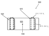
도 8은 본 발명의 일 실시예에 따른 예시적인 용기 체적 교정 시스템의 편평한 2차원 도면이고;
도 9는 본 발명의 일 실시예에 따른 예시적인 용기 체적 교정 시스템의 편평한 2차원 도면이다.1 is a schematic diagram showing an exemplary configuration of a system for calibrating a volume of a storage container according to an embodiment of the present invention;
2 is a block diagram showing an exemplary configuration of a control computer according to an embodiment of the present invention;
3 is a flow diagram illustrating a routine illustrating a system and method for calibrating a reservoir volume in accordance with one embodiment of the present invention;
4A is a simplified plan view of an exemplary container volume calibration system, in accordance with an embodiment of the present invention;
4B is a side view of the example vessel volume calibration system of FIG. 4A;
FIG. 4C shows a flat two-dimensional view of the exemplary container volume correction system of FIG. 4A;
FIG. 4D is a conceptual linear graphical representation of an acoustic signal path in the example vessel volumetric calibration system of FIG. 4A;
5A is a simplified top view of an exemplary vessel volume calibration system in accordance with an embodiment of the present invention;
FIG. 5B is a conceptual linear graphical representation of the acoustic signal path in the exemplary vessel volumetric calibration system of FIG. 5A;
6A is a simplified side view of an exemplary container volume calibration system, in accordance with an embodiment of the present invention;
FIG. 6B is a flat two-dimensional view of the exemplary container volume correction system of FIG. 6A in accordance with an embodiment of the present invention, conceptually illustrating an acoustic signal path; FIG.
6C is a simplified side view of an exemplary bin volume calibration system, in accordance with an embodiment of the present invention;
FIG. 6D is a flat two-dimensional view of the exemplary container volume correction system of FIG. 6C in accordance with an embodiment of the present invention, and is a conceptual diagram of an acoustic signal path; FIG.
FIG. 6E is a flat two-dimensional view of the exemplary container volume correction system of FIG. 6C in accordance with one embodiment of the present invention, conceptually illustrating an acoustic signal path; FIG.
7 is a flat two-dimensional view of an exemplary container volume correction system in accordance with one embodiment of the present invention;
8 is a flat two-dimensional view of an exemplary container volume correction system in accordance with one embodiment of the present invention;
9 is a flat two-dimensional view of an exemplary container volume correction system, in accordance with an embodiment of the present invention.
개요 및 소개를 통해, 저장 용기의 체적을 교정하기 위한 시스템 및 방법이 개시된다. 보다 구체적으로, 본 명세서에 개시된 시스템 및 방법은 음향 또는, 보다 일반적으로, 기계적 파동 기반 검사 기술을 사용하여 이러한 탱크의 체적을 계산하도록 대형 석유 저장 탱크의 치수를 측정하고 결정하는 것에 관한 것이다. 바람직하게는, 시스템은 현장에서 용기를 사용하는 동안 필요에 따라 용기의 외부로부터 교정을 수행하도록 구성된다.With an overview and introduction, a system and method for calibrating the volume of a reservoir is disclosed. More specifically, the systems and methods disclosed herein relate to measuring and determining the dimensions of large oil storage tanks to calculate the volume of such tanks using acoustic or, more generally, mechanical wave-based inspection techniques. Preferably, the system is configured to perform calibration from the outside of the container as needed while using the container in the field.
음향 시험은 시험 중인 재료(예를 들어, 용기의 벽)에서 음파의 전파를 분석하는 것에 기반한 비파괴 및 비침습 시험 기술이다. 본 명세서에 기술된 실시예에서, 측정 기술은 일반적으로 원통형이며 일반적으로 강철 또는 다른 금속 및 합금으로 이루어진 대형 저장 용기의 체적을 측정하기 위해 수행된다. 그러나, 개시된 기술 및 시스템은 콘크리트, 복합재, 천연 재료(예를 들어, 목재) 또는 이의 조합과 같은 다른 재료로 이루어진 구조물의 체적을 교정하기 위해 적용될 수도 있다. 또한, 본 명세서에 개시된 시스템 및 기술은 또한 상이한 크기 및 형상을 갖는 용기의 체적을 측정하기 위해 적용될 수 있다. 예를 들어, 예시적인 실시예는 다양한 크기의 개방 또는 폐쇄 베슬, 탱크 및 다른 용기 또는 도관의 체적을 측정하는 데 사용될 수 있다.Acoustic testing is a non-destructive and non-invasive test technique based on analyzing the propagation of sound waves in the material under test (eg, the wall of a container). In the embodiments described herein, the measurement technique is generally cylindrical and is performed to measure the volume of a large storage vessel, which is generally made of steel or other metals and alloys. However, the disclosed techniques and systems may be applied to calibrate the volume of structures made of other materials, such as concrete, composites, natural materials (eg wood) or combinations thereof. In addition, the systems and techniques disclosed herein may also be applied to measure the volume of containers having different sizes and shapes. For example, example embodiments may be used to measure the volume of open or closed vessels, tanks, and other vessels or conduits of various sizes.
일부 예시적인 구성에서, 용기 체적 교정 시스템은 그 동작을 제어하기에 적합한 관련된 전자 하드웨어 및/또는 소프트웨어를 갖는 측정 장치의 어레이를 포함한다. 측정 장치는 (예를 들어, 손, 로봇 등에 의해) 저장 용기의 외면(들)에 부착되도록 구성되어 장치의 어레이를 정의한다. 측정 장치는 음향 장치와 통신하는 진단 컴퓨팅 장치에 의해 용기의 체적을 결정할 수 있는 기계적 또는 음파 기반 측정을 수행하도록 구성된다. 보다 구체적으로, 장치의 어레이는 용기의 벽 내에 또는 벽을 따라 전파되는 신호를 수신, 측정 및 처리하도록 구성된 하나 이상의 센서를 포함한다. 장치의 어레이는 또한 용기의 벽을 따라 전파되는 신호를 생성하도록 구성된 적어도 하나의 신호 발생 요소 또는 "변환기"를 포함한다.In some exemplary configurations, the container volume calibration system includes an array of measurement devices having associated electronic hardware and / or software suitable for controlling their operation. The measuring device is configured to be attached to the outer surface (s) of the storage container (eg by hand, robot, etc.) to define an array of devices. The measuring device is configured to perform a mechanical or sound wave based measurement capable of determining the volume of the container by a diagnostic computing device in communication with the acoustic device. More specifically, the array of devices includes one or more sensors configured to receive, measure, and process signals propagating in or along the walls of the vessel. The array of devices also includes at least one signal generating element or “converter” configured to generate a signal that propagates along the wall of the container.
센서/발생 요소(통칭적으로, "측정 장치"라 함)는 진단 컴퓨팅 장치(이하, 제어기 또는 제어 컴퓨터라 함)에 연결되어 이를 사용하여 제어되고, 이는 소리 발생 요소를 사용한 음향 신호의 생성과 용기의 벽을 통해 센서에서 적어도 제1 음파의 도착(즉, 음향 신호의 "비행 시간"인 "TOF") 간의 시간을 결정하도록 구성된다. 이상적으로, 하나 이상의 센서(들)에 도달하는 추가적인 음파에 대한 유사한 TOF 정보가 또한 측정/수집된다(예를 들어, 용기를 중심으로 제1 파동의 반대 방향으로 이동하는 제2 음파에 대한 비행 시간). 따라서, 용기 벽의 치수(예를 들어, 용기의 원주, 체적, 높이 등)는 소리 임펄스와 방사 음파의 수신 간의 시간에 기초하고 벽의 재료를 통한 음속에 기초하여 제어기에 의해 이러한 기하학적 정보를 사용하여 계산될 수 있다. 더욱이, 용기의 내부 체적은 벽의 기하학적 측정 및 벽 두께와 같은 용기의 다른 기지의 특성에 기초하여 교정/측정될 수 있다.A sensor / generating element (collectively referred to as a "measuring device") is connected to and controlled using a diagnostic computing device (hereinafter referred to as a controller or control computer), which is responsible for the generation of acoustic signals using sound generating elements and And to determine the time between the arrival of at least the first sound wave (ie, "TOF", the "flight time" of the acoustic signal) at the sensor through the wall of the container. Ideally, similar TOF information for additional sound waves reaching one or more sensor (s) is also measured / collected (e.g., flight time for a second sound wave traveling in the opposite direction of the first wave about the vessel). ). Thus, the dimensions of the vessel wall (e.g. the circumference, volume, height, etc. of the vessel) use this geometric information by the controller based on the time between the reception of the sound impulse and the radiated sound waves and based on the speed of sound through the material of the wall. Can be calculated. Moreover, the interior volume of the vessel can be calibrated / measured based on the geometric measurements of the wall and other known properties of the vessel such as wall thickness.
일부 기본 구성에서, 저장 용기의 체적을 교정하기 위한 시스템은 하나의 변환기 및 하나의 센서를 포함한다. 보다 복잡한 구성에서, 시스템은 다중 레벨(즉, 수직 방향으로 상이한 높이)로 용기 상에 배치되고 및/또는 상이한 원주 위치에 배치된 (즉, 용기의 둘레에 대해 이격된, 예를 들어 평면도에서 용기를 볼 때 9시 위치에 하나의 장치 및 3시 위치에 다른 장치) 복수의 센서를 포함한다. 서로에 대한 센서의 배치에 기초하여, 검출된 신호 정보는 제어 컴퓨터(110)에 의해 각 위치의 각각 및 이에 따른 용기의 정확한 치수를 다차원으로 정확하게 삼각 측량하고 검증하는 데 사용될 수 있다. 그 결과, 용기의 2차원 맵 또는 3차원 맵은 용기의 외벽을 효과적으로 "펼침(unwrapping)"으로써 기하학적 원리를 이용하여 생성될 수 있다.In some basic configurations, the system for calibrating the volume of the reservoir includes one transducer and one sensor. In more complex configurations, the system is disposed on the container at multiple levels (ie, different heights in the vertical direction) and / or at different circumferential positions (ie, spaced apart about the perimeter of the container, for example in a plan view). When viewed, one device at the 9 o'clock position and a plurality of sensors) at the 3 o'clock position. Based on the placement of the sensors relative to each other, the detected signal information can be used by the
다른 현저한 양태에 따르면, 개시된 교정 시스템은 하나 이상의 전송 및 감지 장치를 용기 체적 교정 공정 이전 및/또는 동안의 위치로, 예를 들어 교정 중인 용기의 외부에 다양한 측정 장치를 배치하는 로봇을 사용하여, 제어 가능하게 이동시키도록 구성될 수 있다. 이러한 실시예에서, 다양한 상이한 방향/치수의 정렬은 용기의 체적 계산을 향상시키기 위해 측정 장치 중에 달성될 수 있다.According to another prominent aspect, the disclosed calibration system uses a robot to position one or more transfer and sensing devices to a position before and / or during a container volume calibration process, for example outside of the container under calibration, Controllable movement. In such embodiments, various different orientations / dimensions of alignment may be achieved during the measurement device to improve the volumetric calculation of the container.
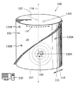
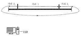
저장 용기(100)의 체적을 교정하기 위한 예시적인 시스템이 도 1에 도시되어 있다. 도 1에 도시된 바와 같이, 용기 체적 교정 시스템(100)은 원통형 형상을 갖는 금속 저장 용기(150)의 체적을 측정하도록 배치된 측정 장치의 "어레이"로서 구현된다. 전술한 바와 같이, 예시적인 실시예는 대체로 원통형 형상을 갖는 저장 용기(예를 들어, 150)의 체적을 측정하는 맥락에서 설명된다. 예를 들어, 제한 없이 실린더 둘레는 벽의 상이한 높이에서 다를 수 있고, 실린더는 벽의 불균일한 곡률을 가질 수 있고 기하학적으로 다른 변형을 가질 수 있음에 따라 원통형 용기는 반드시 정확한 실린더일 필요가 없다는 것을 이해할 수 있다.An exemplary system for calibrating the volume of the
"종축"(116)이라는 용어는 용기의 중심 축을 지칭하는 것으로 의도된다. 도 1에 도시된 바와 같이, 종축(116)은 (예를 들어, 용기가 지면에 고정되거나 배치되는) 용기의 베이스와 용기의 대향 상단 사이에서 연장되는 중심 축이다. 간략화를 위해, 개시된 실시예는 원통형 용기의 베이스가 편평한 지면에 고정되고 종 방향(즉, 용기의 지면/베이스에 대한 수직 방향)으로 상방을 향해 연장된다는 가정하에 설명된다. 따라서, "종 방향"(116)이라는 용어는 종축에 평행한 방향을 지칭하는 것으로 의도된다. 이해할 수 있는 바와 같이, 용기가 지면에 고정된 것으로 가정하고, 베이스로부터 멀어지면, 종축을 따라, 음향 장치가 용기 벽의 외면에 대해 배치될 수 있는 용기의 단면을 통해 연장되는 무한 세트의 횡 방향 또는 "위도" 평면이 존재한다.The term "vertical axis" 116 is intended to refer to the central axis of the container. As shown in FIG. 1, the
2개의 장치가 종축에 대해 수직하고 용기를 이등분하는 평면인 동일한 횡 방향 또는 위도 평면에 있는 용기의 표면에서 각 위치를 가질 때 이들 장치는 "종 방향"으로 (또는, "종 방향 정렬"이라고도 함) 정렬된다. 다시 말해서, "종 방향"으로 정렬된 것으로 지칭된 장치는 종축을 따라 용기의 베이스에 대해 측정된 것과 동일한 높이(즉, 위도)를 갖는다(예를 들어, 두 장치 모두 베이스로부터 종 방향으로 측정되었지만 각각 상이한 각도 위치를 갖는 것처럼 지면에서 9피트 떨어져 있다).When two devices have an angular position on the surface of the container in the same transverse or latitude plane, which is a plane that is perpendicular to the longitudinal axis and bisects the container, these devices are also referred to as "longitudinal" (or "longitudinal alignment"). ) Is sorted. In other words, a device referred to as being "aligned in the longitudinal direction" has the same height (i.e. latitude) as measured for the base of the container along the longitudinal axis (e.g., both devices were measured longitudinally from the base 9 feet from the ground as if each had a different angular position).
원통형 용기는 3차원 표면이기 때문에, "원주 방향"(118)이라는 용어는 용기의 둘레에 대해 그리고 종축(116)에 수직인 하나 이상의 각도 방향을 지칭하는 것으로 의도된다. 특히, 용기의 둘레에 대한 원주 방향은 반시계 방향(114) 및 시계 방향(112)을 포함한다. 원주 방향(118)은 횡 방향이며, 이는 각각의 위도에서 종 방향에 수직인 표면을 따른 하나 이상의 방향을 지칭하는 것으로 이해될 수 있다.Since the cylindrical container is a three-dimensional surface, the term “circumferential direction” 118 is intended to refer to one or more angular directions that are perpendicular to the perimeter of the container and perpendicular to the
표면(155) 상의 각각의 위치가 동일한 종 방향 평면(즉, 종축을 통해 그를 따라 연장되는 평면)에 있고, 그리고 바람직하게는, 장치가 용기의 반대편에 있을 때, 장치는 횡 방향 또는 "원주 방향"으로 정렬된 것으로 본 명세서에서 언급된다. 예를 들어, (원통형 용기(150)가 평면도에서 볼 때) 0도 기준 반경(102) 에 대해 각도 위치 +270도 및 +90에 각각 위치된 2개의 장치는 표면 상의 각각의 위도에 관계없이 원주 방향으로 정렬된다.Each position on the
용기의 원주 벽의 표면이 또한 본 명세서에서 2차원 공간에서 "펼쳐진" 2차원 표면으로 설명되기 때문에, 원주 방향(118)은 "수평 방향"(즉, 수직 방향에 수직이고 지면에 평행함)으로, 또는 더 일반적으로, 횡 방향으로 지칭될 수 있다.Since the surface of the circumferential wall of the container is also described herein as a "unfolded" two-dimensional surface in two-dimensional space, the
용기 체적을 측정하기 위한, 즉 원통 형상 및 금속 구조를 갖는 대형 오일 저장 용기의 체적을 측정하기 위한, 예시적인 시스템 및 방법이 특정한 실제 적용의 맥락에서 본 명세서에 추가로 설명되지만, 본 발명은 이러한 예시적인 적용에 한정되지 않는 것으로 이해되어야 한다. 예를 들어, 일부 구현예에서, 실린더는 중심 축이 지면에 대해 수평으로 연장되도록 배향될 수 있다. 본 명세서에 개시된 예시적인 기술은 다른 형상을 갖는 용기, 예를 들어 구형 탱크의 체적을 교정하는 데 유사하게 적용 가능하지만, 이러한 대안적인 용기 형상은 용기 체적을 계산하기 위해 상이한 세트의 기지의 파라미터(예를 들어, 측정 장치 간의 상대적인 배치 또는 거리)를 필요로 할 수 있음을 이해할 수 있다.Although the exemplary systems and methods for measuring the container volume, ie for measuring the volume of a large oil storage container having a cylindrical shape and a metal structure, are further described herein in the context of certain practical applications, the present invention provides such a It should be understood that it is not limited to the exemplary application. For example, in some embodiments, the cylinder can be oriented such that the central axis extends horizontally with respect to the ground. While the example techniques disclosed herein are similarly applicable for calibrating volumes of vessels with other shapes, such as spherical tanks, these alternative vessel shapes can be used to determine different sets of known parameters for calculating vessel volume. For example, relative arrangement or distance between the measuring devices).
다른 측면에서, 전술한 바는 용기 및 서로에 대한 장치의 위치 결정을 설명하고 장치가 이동되고 정렬될 수 있는 다양한 방향을 설명하기 위한 하나의 예시적인 관례를 설명한다는 것을 이해해야 한다. 본 발명의 개시된 실시예의 범위를 벗어나지 않고 장치의 위치 결정 및 이동을 설명하기 위해 다른 관례 및 용어가 사용될 수 있고, 예를 들어 일반적으로 동일한 위도를 갖는 두 점으로 위도 정렬(또한 원주 방향 정렬)을 나타낼 수 있지만, (서로 수직으로) 동일한 경도를 갖는 두 점으로 종 방향 정렬을 나타낼 수 있다. 이러한 관례에 따르면, 예를 들어 변환기를 원주/위도 방향으로 이동시키면 변환기가 원주 방향으로 정렬된 모든 센서를 통해 이동하여 그 센서와의 거리 측정을 획득할 수 있다.In other aspects, it should be understood that the foregoing describes one exemplary practice for describing the positioning of containers and devices relative to each other and for describing various directions in which the devices may be moved and aligned. Other conventions and terminology may be used to describe the positioning and movement of the device without departing from the scope of the disclosed embodiments of the present invention, for example, by latitude alignment (also circumferential alignment) with two points generally having the same latitude. It can be shown, but the longitudinal alignment can be represented by two points having the same hardness (vertically to each other). According to this convention, for example, moving a transducer in the circumferential / latitude direction allows the transducer to move through all the sensors arranged in the circumferential direction to obtain a distance measurement with the sensor.
시스템(100)은 용기(150)의 측벽(155)의 외면 상에 (예를 들어, 손, 로봇 등에 의해) 배치되도록 구성된 하나 이상의 센서를 포함한다. 도 1에 도시된 바와 같이, 복수의 음향 센서(120A, 120B 및 120C)(용기의 반대편에 도시됨)가 센서의 어레이를 정의하기 위해 측벽 상에 배치된다. 또한, 시스템(100)은 기계적 신호, 보다 구체적으로, 음향 신호를 센서에 의한 검출에 적합한 용기의 벽에 생성하고 인가하도록 구성되는 적어도 하나의 신호 발생 유닛(130A)(이하, "변환기"라 함)을 포함한다. 일부 구현예에서 추가적인 변환기(130B)가 사용될 수도 있다. 바람직하게는, 각 변환기(예를 들어, 130A)는 원점으로부터 방출되어 벽의 표면을 따라 이동하는 신호를 생성한다. "벽을 통해" 이동하는 용어는 벽의 전체 두께를 통과하고 벽과 경계를 이루는 용기의 내부 체적(160)을 가로지르는 신호와 반대로, 벽의 두께 내에서 또는 벽의 표면을 따라 전파되는 신호를 의미하는 것으로 의도된다. 신호는 벽이 연장되는 하나 이상의 방향으로(예를 들어, 용기의 둘레를 중심으로 원주 방향(118)으로, 종 방향(116)으로, 및/또는 이들의 조합 방향으로) 벽을 통해 전파된다. 도 1에 도시된 원통형 저장 용기 상의 시스템(100)의 예시적인 구현예에서, 신호는 일반적으로 시계 방향(112) 및 반시계 방향(114)으로 용기의 벽에 대하여 원주 방향으로 이동하는 것이 바람직하다. 그러나, 일부 구현예에서, 하나 이상의 변환기가 용기의 내부 체적을 통해 신호를 전송하도록 구성될 수 있음을 이해할 수 있다.
다양한 유형의 신호 또는 "파동"은 변환기와 센서를 사용하여 전송되고 검출될 수 있다. 언급한 바와 같이, 신호는 일반적으로 광범위한 범주의 기계적 파동 및, 본 명세서에 기술된 비제한적인 예시적인 구현예에서, 음파에 속한다. 일부 구현예에서, 센서가 하나 이상의 상이한 유형의 파동을 검출하도록 구성될 수 있기 때문에, 거리 측정은 재료 자체 내에서 이동하는 표면파 및/또는 압축파에 기초할 수 있다. 매체에서 파동 속도의 정확한 교정을 가정하면, 측정되는 특정 유형의 파동은, 파동의 추정 속도가 일정하게 유지되는 한, 해당 거리 측정에 반드시 영향을 미치지는 않는다.Various types of signals or "waves" can be transmitted and detected using transducers and sensors. As mentioned, signals generally belong to a broad range of mechanical waves and, in the non-limiting exemplary embodiments described herein, sound waves. In some implementations, because the sensor can be configured to detect one or more different types of waves, the distance measurement can be based on surface waves and / or compressed waves traveling within the material itself. Assuming correct calibration of the wave velocity in the medium, the particular type of wave being measured does not necessarily affect the distance measurement as long as the estimated velocity of the wave remains constant.
일부 구현예에서, 표면파에 기초한 측정은 가장 급격한 진폭을 갖는 표면에 대해 상하로 이동하고 더 용이하게 검출할 있으므로 바람직할 수 있다. 일반적으로, 1차 파동은 매체를 통해 이동하므로 2차 파동보다 더 빠르게 이동할 수 있으며, 표면파는 2차 파동보다 더 느리게 이동한다. 따라서, 센서를 이용하여 다수 유형의 파동이 검출되는 경우, 각 파동 유형이 센서에 도달하는 시간의 차이는 거리를 보다 정확하게 측정하는 데 이용될 수 있다. 예를 들어, 시스템은 센서에서 1차 파동과 2차 파동 도달 시간 간의 차이를 측정하여 거리를 결정한 후, 본 명세서에서 더 설명될 바와 같이, 각각의 장치 위치를 삼각 측량하도록 구성될 수 있다.In some embodiments, measurements based on surface waves may be desirable as they move up and down and are easier to detect for surfaces with the sharpest amplitudes. In general, the primary wave travels through the medium, so it can travel faster than the secondary wave, and the surface wave travels slower than the secondary wave. Thus, when multiple types of waves are detected using the sensor, the difference in the time each wave type reaches the sensor can be used to measure the distance more accurately. For example, the system may be configured to measure the difference between the primary wave and the secondary wave arrival time at the sensor to determine the distance, and then triangulate each device location, as described further herein.
도 1에 도시된 바와 같이, 센서 및 변환기(들)는 용기 체적 교정 시스템(100) 및 다양한 측정 장치의 작동을 조정하도록 구성된 제어 컴퓨터(110)에 전기적으로 연결된다(연결 수단 미도시). 제어 컴퓨터(110)는, 본 명세서에서 더 설명될 바와 같이, 시스템(100)의 다양한 장치와 통신하고, 전자 정보를 수신, 전송 및 저장하고 그 정보를 처리하여 저장 용기의 체적을 측정하고 교정할 수 있는 컴퓨팅 장치 및/또는 데이터 처리 장치이다. 도 2와 관련하여 더 설명된 바와 같이, 제어 컴퓨터는 기계 구현 가능 코드의 형태로 하나 이상의 소프트웨어 모듈을 실행하는 프로세서(미도시)를 포함하고, 그렇게 함으로써, 변환기 및 센서에 의한 신호의 송수신을 각각 제어하도록 구성된다. 또한, 소프트웨어는 변환기에 의해 생성되고 센서에 의해 측정된 바와 같은 신호 정보를 분석하고 용기의 다양한 치수(즉, 용기의 기하학적 구조)를 기하학적으로 계산하도록 제어 컴퓨터를 구성한다. 일부 구현예에서, 소프트웨어는 또한 용기의 구조적 조건뿐만 아니라 용기의 다른 동작 특성(예를 들어, 용기 내 내용물의 체적, 내용물을 분류하거나, 용기 벽의 구조적 무결성 등)을 평가하도록 프로세서를 구성할 수도 있다.As shown in FIG. 1, the sensor and transducer (s) are electrically connected to a
보다 구체적으로, 제어 컴퓨터는 변환기(130A)에 의한 하나 이상의 신호 또는 펄스의 생성과 하나 이상의 센서에서 용기의 벽을 통해 이동하는 적어도 제1 파동의 도달 간의 시간을 결정하도록 구성된다. 이상적으로, 센서(들)에 도달하는 추가 파동에 대한 유사한 "비행 시간" 정보는 마찬가지로 제어 컴퓨터(110) 및 장치를 이용하여 측정/수집된다(예를 들어, 제1 파동에 반대 방향으로 용기 주위에서 이동하는 제2 파동에 대한 비행 시간). 따라서, 제어 컴퓨터는 파동의 임펄스와 수신 간의 시간에 기초하고 벽의 재료를 통한 기지의 음속에 더 기초하여 신호에 의해 이동된 거리 및 용기의 치수를 계산하도록 더 구성된다. 벽을 통한 음속은 용기 벽의 재료 특성에 따라 달라질 수 있기 때문에, 일부 구현예에서, 음속은 재료에 기초하여 추정될 수 있다. 추가적으로 또는 대안적으로, 일부 구현예에서, 음속은 시스템(100)을 사용하여 동적으로 계산될 수도 있다. 예를 들어, 기지의 분리를 갖는 둘(2) 이상의 음향 센서는 용기 체적의 교정을 알려주는 음속 측정을 교정하는 데 사용될 수 있다.More specifically, the control computer is configured to determine the time between the generation of one or more signals or pulses by
바람직하게는, 어레이는 저장 용기의 벽에 다중 레벨로 (예를 들어, 같은 높이로 추정되는 용기(157)의 베이스로부터 종 방향(116)으로 측정된 바와 같은 상이한 높이로) 배치된 복수의 센서를 포함한다. 일부 구현예에서, 하나 이상의 종 방향(116) 및 원주 방향(118)으로 기지의 양만큼 이격된 센서 및/또는 임펄스 발생기가 용기에 적용될 수 있다. 예를 들어, 다수의 이격된 센서 스트립이 사용될 수 있다. 본 명세서에서 더 설명된 바와 같이, 기지의 간격을 갖는 적어도 2개의 측정 장치를 이용하면 시스템(100)을 사용하여 용기의 체적을 교정할 때 시스템(100)의 교정 및 정확도 확증을 도울 수 있다. 유사하게, 일부 구현예에서, 센서는 용기 주위의 기지의 높이로 개별적으로 배치될 수 있다. 그 결과, 계산의 정확성과 속도가 향상될 수 있다. 더욱이, 상이한 레벨로 제어된 다수 센서의 배치 및 원주 위치는 센서의 각 위치를 정확하게 삼각 측량하고 검증하는 역할을 한다. 따라서, 2차원 맵의 정확한 크기는 용기의 외벽을 펼쳐서 생성될 수 있다.Preferably, the array comprises a plurality of sensors disposed on the wall of the storage vessel at multiple levels (eg, at different heights as measured in the
일부 구현예에서, 하나 이상의 측정 장치는 장기 또는 영구 교정 시스템을 제공하도록 용기의 외부 상의 각 위치에 부착될 수 있다. 그러나, 일부 구현예에서, 하나 이상의 측정 장치는 일시적으로 배치되어 시스템은 필요에 따라 상이한 용기를 교정하는 데 사용될 수 있다. 또한, 일부 휴대용 교정 시스템 구성에서, 센서는 로봇을 사용하여 배치될 수 있으므로, 센서를 용기에 배치할 때 비계를 필요로 하지 않는다.In some embodiments, one or more measurement devices can be attached at each location on the exterior of the container to provide a long-term or permanent calibration system. However, in some embodiments, one or more measurement devices are temporarily placed so that the system can be used to calibrate different containers as needed. In addition, in some portable calibration system configurations, the sensor can be deployed using a robot, thus eliminating the need for scaffolding when placing the sensor in a container.
센서 : Sensor
센서(120A-120C)는, 당업자에게 이해될 수 있는 바와 같이, 용기의 외면에 장착되고, 용기의 벽으로부터 벽을 따라 방사되는 기계적 파동 신호를 검출 및 수신하고, 그러한 정보를 처리하는 데 적합한 임의의 다양한 센서 또는 송수신기일 수 있다. 바람직하게는, 센서는 표면과 접촉하는 매우 작은 팁을 가져 파동의 검출에 대한 위치 오차를 최소화한다. 팁의 크기는 시스템의 필요 정확도의 함수로 정의될 수 있다. 다양한 유형의 센서로는, 예를 들어 압전 센서, 광대역 음향 변환기 등이 사용될 수 있다.
예를 들어, 일부 구현예에서, 센서는 벽을 따라 전파되는 다양한 기계적 파동 유형, 예를 들어 제한 없이 1차 파동, 2차 파동, 표면파, 레일리 파동 등 중, 하나를 검출하도록 구성되는 압전 센서일 수 있다. 센서가 다수의 상이한 유형의 파동을 검출하도록 구성되는 구현예에서, 센서 및/또는 제어 컴퓨터는 센서에서 수신된 상이한 유형의 파동 간을 구별하는 것이 더 바람직할 수 있다. 또한, 일부 구현예에서, 센서는, 당업자에게 이해될 수 있는 바와 같이, 다양한 방법(예를 들어, 응력/변형, 압력, 진동 등)에 따라 표면의 측 방향 또는 반경 방향 이동을 측정하도록 구성될 수 있다.For example, in some embodiments, the sensor is a piezoelectric sensor configured to detect one of various types of mechanical waves propagating along the wall, for example, without limitation, primary waves, secondary waves, surface waves, Rayleigh waves, and the like. Can be. In embodiments where the sensor is configured to detect a number of different types of waves, it may be more desirable for the sensor and / or control computer to distinguish between different types of waves received at the sensor. Further, in some embodiments, the sensor may be configured to measure the lateral or radial movement of the surface according to various methods (eg, stress / strain, pressure, vibration, etc.), as will be appreciated by those skilled in the art. Can be.
바람직하게는, 센서는 제어 컴퓨터와 전자 통신하여 제어 컴퓨터는 센서의 동작을 제어할 수 있고 센서는 추가 처리를 위해 수신된 신호 데이터를 제어 컴퓨터에 제공할 수 있다.Preferably, the sensor is in electronic communication with the control computer so that the control computer can control the operation of the sensor and the sensor can provide the received signal data to the control computer for further processing.
신호 발생기 : Signal generator :
전술한 바와 같이, 신호 발생 장치(예를 들어, 변환기(130))는, 당업자에 의해 이해될 수 있는 바와 같이, 기계적 및/또는 음향 신호를 용기의 둘레에 대하여 용기의 벽을 통해 또는 벽을 따라 이동하도록 용기의 벽에 인가하기에 적합한 임의의 다양한 변환기 또는 송수신기일 수 있다.As mentioned above, the signal generating device (e.g., transducer 130) is capable of transmitting mechanical and / or acoustic signals through the wall of the container or through the wall of the container, as understood by one of ordinary skill in the art. It may be any of a variety of transducers or transceivers suitable for application to the walls of the vessel to move along.
보다 기본적인 구현예에서, 변환기는 기계적 펄스 또는 파동을 생성시키기 위해 단단한 물체로 용기의 표면을 제어 가능하게 타격하도록 구성된 전자 기계 장치일 수 있다. 추가로 또는 대안적으로, 임펄스 발생기는 음향 변환기일 수 있다. 다음의 설명에서, "음향"이라는 용어는 기계적인 파동 및 음향 신호, 예를 들어 100Hz 내지 50MHz의 주파수 범위, 보다 선택적으로 초음파 음향 방사 범위의 음향 신호를 포함하도록 광범위하게 해석되어야 한다. 그러나, 일부 구현예에서, 더 낮은 주파수를 갖는 신호가 사용될 수 있고, 예를 들어 신호의 원치 않는 반사를 최소화하고 신호의 특정 형태의 용이한 검출을 가능하게 하여 신호의 차별화를 용이하게 함으로써 정확도를 향상시킬 수 있다.In a more basic embodiment, the transducer may be an electromechanical device configured to controllably strike the surface of the container with a rigid object to produce a mechanical pulse or wave. Additionally or alternatively, the impulse generator may be an acoustic transducer. In the following description, the term “acoustic” should be interpreted broadly to include mechanical waves and acoustic signals, eg, acoustic signals in the frequency range of 100 Hz to 50 MHz, more optionally in the ultrasonic acoustic emission range. However, in some implementations, signals with lower frequencies may be used, for example, to improve accuracy by facilitating differentiation of signals by minimizing unwanted reflections of the signal and facilitating easy detection of certain forms of the signal. Can be improved.
각 변환기는 신호를 검출하도록 구성된 센서(들)를 향해 용기의 벽을 따라 이동하는 적어도 하나의 펄스를 포함하는 신호를 생성하도록 구성될 수 있다. 따라서, 각각의 위치에서 변환기(들)를 사용하여 적어도 하나의 기계적 펄스를 생성함으로써, 개별 펄스에 의해 이동된 해당 거리가 측정될 수 있다. 각 변환기는 개별 임펄스/펄스를 포함하는 신호를 전송하도록 구성될 수 있지만, 변환기는 파동, 예를 들어 특정 주파수, 형상, 파장 진폭 등을 갖는 펄스의 스트림을 생성하도록 구성될 수도 있다.Each transducer may be configured to generate a signal comprising at least one pulse traveling along the wall of the container towards the sensor (s) configured to detect the signal. Thus, by generating at least one mechanical pulse using the transducer (s) at each location, the corresponding distance traveled by the individual pulses can be measured. Each transducer may be configured to transmit a signal comprising individual impulses / pulses, but the transducer may also be configured to generate a stream of pulses with a specific frequency, shape, wavelength amplitude, and the like.
변환기는 신호가 펄스의 원점으로부터 멀리 방사되도록 용기의 벽에 신호를 인가하도록 구성될 수 있다. 바람직하게는, 변환기는 벽의 표면을 따라 원점으로부터 신호의 전파를 안내하기 위해 용기의 벽을 도파관으로 사용하도록 구성된다. 일부 구성에서, 변환기는 신호가 제어된 방식으로 용기의 둘레 주위로 전파되도록 하나 이상의 정의된 방향으로 신호가 전파되기 위해 신호를 유입하도록 구성된다.The transducer may be configured to apply the signal to the wall of the vessel such that the signal is radiated away from the origin of the pulse. Preferably, the transducer is configured to use the wall of the vessel as a waveguide to guide the propagation of the signal from the origin along the surface of the wall. In some configurations, the transducer is configured to introduce a signal for propagation in one or more defined directions such that the signal propagates around the perimeter of the container in a controlled manner.
바람직하게는, 변환기는 제어 컴퓨터와 전자 통신하여 제어 컴퓨터는 변환기의 동작을 제어할 수 있다. 일부 구현예에서, 변환기는 특정 특성, 즉 특정 주파수 또는 특정 범위의 주파수를 갖는 신호를 유입하도록 구성될 수 있다. 신호의 특성은 변환기의 특정 하드웨어 구성에 의해 정의될 수 있으며, 추가적으로 또는 대안적으로 제어 컴퓨터를 사용하여 제어될 수 있다.Preferably, the transducer is in electronic communication with the control computer such that the control computer can control the operation of the transducer. In some implementations, the transducer can be configured to introduce a signal having a particular characteristic, ie, a specific frequency or a range of frequencies. The characteristics of the signal can be defined by the specific hardware configuration of the transducer and can additionally or alternatively be controlled using a control computer.
보다 구체적으로, 바람직하게는, 파동은 벽의 한 표면과 다른 표면 사이에서 이동하지 않는데(즉, 에코)(예를 들어, 표면 사이에서 방사상으로 바운스), 이는 파동에 의해 이동된 거리를 인위적으로 증가시키고 리딩 에지 뒤에 이루어진 파동의 일부로 노이즈를 생성할 수 있기 때문이다. 따라서, 일부 구현예에서, 신호의 주파수는 재료 내의 반사를 최소화하도록 교정될 수 있다. 예를 들어, 저주파수 신호를 사용하면, 용기 벽의 두께로 인해 신호가 벽 내에서 바운스할 수 있으므로, 보다 정확한 결과를 초래할 수 있다. 추가의 예로서, 벽의 두께보다 긴 파장을 갖는 신호가 사용될 수 있고 신호가 벽의 두께 내에서 울리도록 유지할 수 있다. 따라서, (예를 들어, 하나(1)의 파장이 벽의 두께에 적합하지 않을 수 있도록) 주파수가 충분히 낮으면, 벽에서의 울림이 최소화되어야 하고, 이에 따라 신호의 전파는 표면을 따라 더 일관되어야 한다.More specifically, preferably, the wave does not move between one surface of the wall and the other surface (ie, echo) (eg, radially bounces between the surfaces), which artificially tracks the distance traveled by the wave. This is because it can increase and generate noise as part of the wave made behind the leading edge. Thus, in some implementations, the frequency of the signal can be calibrated to minimize reflections in the material. For example, using a low frequency signal may result in a more accurate result since the thickness of the vessel wall may cause the signal to bounce within the wall. As a further example, a signal having a wavelength longer than the thickness of the wall can be used and keep the signal ringing within the thickness of the wall. Thus, if the frequency is low enough (eg, one (1) wavelength may not be suitable for the thickness of the wall), ringing at the wall should be minimized so that signal propagation is more consistent along the surface. Should be.
일부 적용예에서, 음파는 특정 주파수에서 서로 간섭할 수 있다. 또한, 주파수가 높을수록 신호의 선명도를 높이고 정확한 검출을 도울 수 있지만, 전술한 바와 같이 신호의 진폭 및/또는 울림이 잠재적으로 손실될 수 있다. 따라서, 제어 컴퓨터 및 변환기는 용기 벽 두께, 둘레 등과 같은 특정 적용에 관한 제약을 고려하여 센서에 도달할 때 각 임펄스의 리딩 에지를 보다 정확하게 검출할 수 있도록 임펄스의 주파수를 변조하도록 구성될 수 있다. 다른 적합한 신호 특성은 본 명세서의 방법 및 시스템에서 선택되거나 변조될 수도 있으며, 예를 들어 펄스의 진폭 및 파장은 변조되거나 정의될 수 있다.In some applications, sound waves may interfere with each other at certain frequencies. In addition, higher frequencies can increase the sharpness of the signal and aid in accurate detection, but can potentially result in loss of amplitude and / or ringing of the signal, as described above. Thus, the control computer and transducer may be configured to modulate the frequency of the impulse to more accurately detect the leading edge of each impulse upon reaching the sensor, taking into account certain application constraints such as vessel wall thickness, perimeter, and the like. Other suitable signal characteristics may be selected or modulated in the methods and systems herein, for example, the amplitude and wavelength of the pulse may be modulated or defined.
로봇 배치 : Robot Placement :
전술한 바와 같이, 일부 구성에서, 시스템(100)은 일시적인 방식으로 교정되는 용기 상에 하나 이상의 측정 장치를 자율적으로 그리고 반자율적으로 배치하도록 구성된 하나 이상의 로봇을 포함할 수 있다. 도 1에 도시된 예시적인 구성에서, 음향 변환기(130A)는 로봇(160)을 사용하여 배치된다. 일부 구성에서, 로봇은 각각의 위치에서 용기에 장치를 부착함으로써 측정 장치를 배치할 수 있다. 따라서, 로봇은 다수의 상이한 측정 장치를 배치할 수 있다. 다른 구성에서, 측정 장치는 로봇에 장착될 수 있어서, 배치는 로봇이 위치로 이동하는 것을 포함하고 장치를 벽(155)과 연통하게 배치한 후 필요에 따라 다른 위치로 이동시킬 수 있다. 이러한 구성에서, 로봇은 시스템에 의해 구현된 코드의 프로그래밍 제어 하에서 그 자체를 재배치하고 선택적으로 장치를 용기와 치합하게 이동시킬 수 있다.As noted above, in some configurations, the
로봇 공학 분야의 당업자에 의해 이해될 수 있는 바와 같이, 각 로봇(160)은 동작 시 로봇을 이동시키기 위한 본체 및 모션 시스템을 포함하는 이동 로봇 장치이다. 로봇은, 예를 들어 태양 전지, 배터리, 또는 임의의 다른 적합한 전원에 의해 전력을 공급받을 수 있다. 로봇은 동작 작업을 용이하게 수행하도록 특별히 설계된 기능적 하드웨어 구성요소, 예를 들어 로봇의 높이, 위치, 배향 등을 검출하기 위한 센서를 포함할 수 있다. 로봇 하드웨어는 용기 체적 교정 공정에서 사용되는 온보드 음향 센서 및 변환기, 및 추가적으로 또는 대안적으로 독립형 방식으로 작동하도록 구성된 측정 장치를 운반하고 배치하기에 적합한 구성요소를 포함할 수도 있다. 로봇은 용기 체적 교정 작동의 성능을 용이하게 하는 구성 설정 및 하나 이상의 제어 프로그램과 같은 로봇의 동작과 관련된 정보를 저장하도록 구성된 메모리 및/또는 컴퓨터 판독 가능 저장 매체를 포함하는 전자 회로를 본체 내에 포함할 수 있다.As will be appreciated by those skilled in the art of robotics, each
현저한 측면에 따르면, 일부 실시예에서, 시스템(100)은 자동화된 방식으로 용기 체적을 정확하게 측정하도록 용기 체적 교정 공정의 구현 이전 및/또는 동안 측정 장치를 위치에 (예를 들어, 손으로 또는 로봇을 사용하여) 제어 가능하게 배치하도록 구성될 수 있다. 보다 구체적으로, 로봇 기반 배치 솔루션은 더 복잡한 교정 절차를 높은 정밀도로 자동 실행하도록 구현될 수 있어, 임의의 다수의 상이한 센서에 대한 기계적 또는 음파 기반 측정 및 변환기 배치 방식을 획득함으로써 용기 교정 결과의 정확성을 향상시킬 수 있다. 예를 들어, 로봇은 제어 컴퓨터(110)에 의해 제어되어 센서 및/또는 변환기를 용기 벽 상의 상이한 위치(예를 들어, 다양한 높이, 상대 위치, 절대 위치 등)로 체계적으로 이동시킬 수 있어, 음향 측정은 장치의 각 배치에 대해 이루어질 수 있고 이후 측정은 개별적으로 조합하여 용기의 형상, 보다 구체적으로 용기 체적의 상세한 맵을 생성하기 위해 분석될 수 있다.According to a remarkable aspect, in some embodiments, the
예시적인 제어 컴퓨터(110)를 도 2를 참조하여 더 설명한다. 도시된 바와 같이, 제어 컴퓨터(110)는 회로 보드(215), 프로세서(210), 메모리(220), 디스플레이(235), 사용자 인터페이스(225), 통신 인터페이스(250), 및 컴퓨터 판독 가능 저장 매체(290)를 포함하는 시스템(100)의 동작을 가능하게 하는 다양한 하드웨어 및 소프트웨어 구성요소로 배열될 수 있다.An
프로세서(210)는 스토리지(290)에 저장되어 메모리(220)에 로딩될 수 있는 소프트웨어 명령을 실행하는 역할을 한다. 프로세서(210)는 특정 구현에 따라 다수의 프로세서, 다중 프로세서 코어, 또는 일부 다른 유형의 프로세서일 수 있다. 디스플레이는 터치 스크린 또는 입력 장치(미도시)에 작동 가능하게 연결된 다른 디스플레이 상에 디스플레이될 수 있다.The
바람직하게는, 메모리(220) 및/또는 스토리지(290)는 프로세서(210)에 의해 접속 가능하여, 프로세서(210)가 메모리(220) 및/또는 스토리지(290)에 저장된 명령을 수신 및 실행할 수 있다. 메모리(220)는, 예를 들어 랜덤 액세스 메모리(RAM) 또는 임의의 다른 적합한 휘발성 또는 비휘발성 컴퓨터 판독 가능 저장 매체일 수 있다. 또한, 메모리(220)는 고정식 또는 이동식일 수 있다. 스토리지(290)는 특정 구현에 따라 다양한 형태를 취할 수 있다. 예를 들어, 스토리지(290)는 하드 드라이브, 플래시 메모리, 재기록 가능 광 디스크, 재기록 가능 자기 테이프, 또는 이들의 일부 조합과 같은 하나 이상의 구성요소 또는 장치를 포함할 수 있다. 스토리지(290)는 고정식 또는 이동식 로컬 스토리지, 또는 클라우드 기반 데이터 저장 시스템과 같은 원격 스토리지일 수 있다.Preferably,
하나 이상의 소프트웨어 모듈(230)은 스토리지(290) 및/또는 메모리(220)에 인코딩된다. 소프트웨어 모듈(230)은 컴퓨터 프로그램 코드, 스크립트, 또는 프로세서(210)에서 실행되는 한 세트의 해석 가능 명령을 갖는 하나 이상의 소프트웨어 프로그램 또는 응용 프로그램을 포함할 수 있다. 본 명세서에 개시된 시스템 및 방법의 동작을 수행하고 양태를 구현하기 위한 이러한 컴퓨터 프로그램 코드 또는 명령은 하나 이상의 프로그래밍 언어 또는 스크립트의 임의의 조합으로 작성될 수 있다. 프로그램 코드는 독립형 소프트웨어 패키지로서, 전체적으로 제어 컴퓨터(110) 상에서, 부분적으로는 제어 컴퓨터 상에서 그리고 부분적으로는 원격 컴퓨터/장치(예를 들어, 센서, 변환기 및/또는 로봇) 상에서 또는 전체적으로 이러한 원격 컴퓨터/장치 상에서 실행될 수 있다. 후자의 시나리오에서, 원격 컴퓨터 시스템은 근거리 통신망(LAN) 또는 광역 통신망(WAN)을 포함하는 임의 유형의 전자 데이터 연결 또는 네트워크를 통해 제어 컴퓨터(110)에 연결될 수 있거나, 또는 그 연결은 외부 컴퓨터(예를 들어, 인터넷 서비스 공급자를 이용하여 인터넷을 통해) 이루어질 수 있다.One or
바람직하게는, 소프트웨어 모듈(230) 중에는 프로세서(210)에 의해 실행되는 신호 제어 모듈(270), 신호 분석 모듈(272), 기하학적 분석 모듈(274), 위치 제어 모듈(276)이 포함된다. 소프트웨어 모듈(230)의 실행 동안, 프로세서(210)는 더 상세히 후술될 바와 같이 저장 용기의 교정과 관련된 다양한 동작을 수행하도록 구성된다.Preferably, the
당업자에게 알려진 바와 같이, 소프트웨어 모듈(230)의 프로그램 코드 및 하나 이상의 비일시적 컴퓨터 판독 가능 저장 장치(예를 들어, 메모리(220) 및/또는 스토리지(290))는 본 개시물에 따라 제조될 수 있고 및/또는 배포될 수 있는 컴퓨터 프로그램 제품을 형성한다고 말할 수도 있다.As is known to those skilled in the art, the program code of the
일부 예시적인 실시예에서, 하나 이상의 소프트웨어 모듈(230)은 필드 로봇(100)을 구성하기 위한 시스템 내에서 사용하기 위해 통신 인터페이스(250)를 통해 다른 장치 또는 시스템으로부터 네트워크를 통해 스토리지(290)로 다운로드될 수 있음을 이해해야 한다.In some demonstrative embodiments, one or
또한, 본 시스템 및 방법의 작동과 관련된 다른 정보 및/또는 데이터, 예를 들어 사용 시 측정 장치(예를 들어, 센서 및 변환기) 및/또는 로봇의 작동에 사용되는 다양한 제어 프로그램이 스토리지(290)에 저장될 수 있음에 유의해야 한다.In addition, various information and / or data related to the operation of the present systems and methods, such as various control programs used for the operation of measuring devices (eg sensors and transducers) and / or robots in use, may be stored in the
데이터베이스(285)는 스토리지(290)에 저장될 수도 있다. 데이터베이스(285)는 시스템(100)의 다양한 동작 전체에 걸쳐 이용되는 다양한 데이터 항목 및 요소를 포함하고 및/또는 유지할 수 있다. 데이터베이스(185)에 저장된 정보는 측정 장치의 동작을 조정하기 위한 소프트웨어 및 정보, 용기 교정 시 각 위치에 측정 장치를 배치하면서 로봇의 움직임을 조정하기 위한 소프트웨어 및 정보, 음향 측정을 수행하고 용기 치수(예를 들어, 용기 벽 두께, 용기 벽 재료 조성, 용기 내용물, 용기 높이, 용기의 개략적 치수)를 계산하는 데 사용되는 용기의 기지의 특성을 포함할 수 있지만, 이에 한정되는 것은 아니다. 데이터베이스(285)가 제어 컴퓨터(110)의 스토리지에 국부적으로 구성되는 것으로 도시되어 있지만, 특정 구현예에서, 데이터베이스(285) 및/또는 그에 저장된 다양한 데이터 요소는 원격으로 위치되고 당업자에게 공지된 방식으로 네트워크를 통해 제어 컴퓨터(110)에 연결될 수 있음을 유의해야 한다.
통신 인터페이스(250)는 또한 프로세서(210)에 작동 가능하게 연결되며, 제어 컴퓨터(110)와 외부 장치, 교정 동작과 관련하여 사용되는 변환기, 센서 및 로봇과 같은 기계 및/또는 요소 간의 통신을 가능하게 하는 임의의 인터페이스일 수 있다. 바람직하게, 통신 인터페이스(250)는 모뎀, 네트워크 인터페이스 카드(NIC), 통합 네트워크 인터페이스, 무선 주파수 송신기/수신기(예를 들어, 블루투스, 셀룰러, NFC), 위성 통신 송신기/수신기, 적외선 포트, USB 연결 장치, 및/또는 제어 컴퓨터(110)를 다른 컴퓨팅 장치 및/또는 사설 네트워크 및 인터넷과 같은 통신 네트워크에 연결하기 위한 임의의 다른 인터페이스를 포함하지만, 이에 한정되는 것은 아니다. 이러한 연결은 유선 연결 또는 무선 연결(예를 들어, IEEE 802.11 표준을 사용함)을 포함할 수 있지만, 통신 인터페이스(250)는 제어 컴퓨터와의 통신을 가능하게 하는 실질적으로 임의의 인터페이스일 수 있음을 이해해야 한다.The
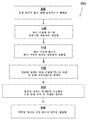
용기 체적을 교정하기 위한 시스템(100) 및 전술한 다양한 요소 및 구성요소의 작동은 도 3을 참조하면 더 이해될 것이다. 도 3은 본 발명의 실시예에 따른 저장 용기의 체적을 교정하기 위한 루틴(300)의 요소를 나타낸 개괄적인 흐름도이다. 도 3의 방법은 도 4a 내지 도 4d에 도시된 시스템(100)의 예시적인 실제 구현예를 참조하여 논의되지만, 루틴(300)은 도 5a 내지 도 9의 맥락에서 설명된 예시적인 교정 시스템 구성 및 공정과 관련하여 유사하게 적용될 수 있음을 이해해야 한다.Operation of the
루틴(300)은 음향 장치가 각 위치에서 용기에 물리적으로 배치될 때 단계 305에서 시작한다. 보다 구체적으로, 하나 이상의 음향 센서 및 하나 이상의 음향 변환기는 손으로 또는 로봇을 사용하여 용기 벽의 외면 상의 각 위치에 배치될 수 있다. 바람직하게는, 하나 이상의 센서는 벽에 음향적으로 결합되어 표면을 따라 이동하는 음향 신호를 검출하도록 구성된다. 변환기는 표면에 음향적으로 결합되고, 일 실시예에서, 원점에서 벽에 인가되는 하나 이상의 펄스를 생성하도록 구성되어 음파가 표면을 따라 변환기의 위치로부터 멀리 방사하게 된다. 음향 장치의 "위치"는 장치가 음향 신호를 송신 및/또는 수신하는 용기 표면 상의 위치(예를 들어, 지점 또는 영역)를 나타내는 것으로 이해되어야 한다. 또한, 바람직하게는, 음향 센서는 측정에서 요구되는 정확도를 달성하기 위해 적절한 크기를 갖는 표면과 접촉하는 팁을 가지며, 이에 따라 음파의 검출 오류를 최소화한다. 예를 들어, 센서 팁은 거리 기반 측정에 필요한 정확도 허용 오차보다 작은 직경을 가질 수 있다.The routine 300 begins at
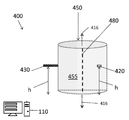
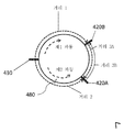
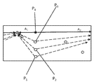
도 4a는 음향 장치, 즉 변환기(430) 및 원통형 용기(450)의 벽(455)의 외면 상에 배치된 제1 센서(420A)를 포함하는 예시적인 용기 체적 교정 시스템(400)의 단순화된 평면도이다. 음향 장치(430 및 420A)와 통신하고 그 동작을 조정하도록 구성된 제어 컴퓨터(110)가 또한 도시되어 있다. 용기(450) 상에 배치된 시스템(400)의 측면도인 도 4b에 도시된 바와 같이, 변환기(430) 및 제1 센서(420A)는 (종 방향(416)으로 측정되는) 용기의 벽 상의 동일한 높이(h)에 위치되어, 종 방향으로 (즉, 전술한 바와 같이 동일한 위도에서) 정렬된다. 변환기와 센서가 동일한 위도에 (즉, 음향 신호가 그들 사이에서 가장 직접/가장 짧은 원주 경로를 따라 변환기에서 센서로 이동할 수 있도록) 제공되는 것으로 가정하면, 다음의 예시적인 루틴(300)의 단계가 시스템(400)을 사용하여 수행되어 음향 장치의 주어진 위도에서 용기의 둘레를 계산할 수 있다. 추가 센서(420)(예를 들어, 420B, 420C 등)가 도 5a 내지 도 9와 관련하여 논의된 임의의 주어진 배치에서 이용될 수 있음을 이해해야 한다.4A is a simplified plan view of an exemplary container
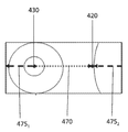
단계 310에서, 하나 이상의 펄스가 변환기를 사용하여 생성된다. 실제 적용에서, 예를 들어 제한 없이 신호 제어 모듈(270)을 사용하여 하나 이상의 소프트웨어 모듈을 실행함으로써 구성되는 제어 컴퓨터(110)는 변환기(430)가 펄스를 생성하게 할 수 있다. 제어 컴퓨터는, 예를 들어 임펄스 시간을 포함하는 펄스에 관한 다양한 파라미터를 기록할 수도 있다. 다른 파라미터는 세기, 주파수 등과 같은 펄스의 특성을 포함할 수 있다. 바람직하게는, 펄스는 변환기의 각 위치로부터 벽(455)에 인가되고 벽의 표면을 따라 원점으로부터 외측 방향으로 방사된다. 특히, 펄스의 제1 성분("제1 음파")은 시계 방향으로 표면을 따라 이동하고, 음파의 제2 성분("제2 음파")은 반시계 방향으로 용기의 표면을 따라 이동한다. 도 4c는 (벽이 도 4a 및 4b에 도시된 가상의 분할 선(480)을 따라 절단되고 펼쳐진/편평한 것처럼) 벽의 내면의 관점에서 용기 벽의 편평한 2차원 도면을 도시하고 있다. 도 4c는 펄스의 원점(즉, 변환기(430)의 위치)으로부터 방사되는 음파를 도시하고 있다. 효과적으로, 도 4c에 도시된 바와 같이, 제1 음파는 제1 경로(470)를 따라 원점으로부터 센서(420A)의 위치로 이동하고, 제2 음파는 제2 경로(475)를 따라 이동한다.In
이제 루틴(300)으로 돌아가면, 단계 315에서, 하나 이상의 펄스가 하나 이상의 센서를 사용하여 검출된다. 도 4a 내지 도 4d에 도시된 음향 장치의 특정한 상대 배치를 고려하면, 제1 음파는 제2 음파("거리 2")보다 센서(420A)에 도달하기 전에 더 긴 거리("거리 1")를 이동한다. 그 결과, 제2 음파의 도착은 제1 음파의 도착 전에 센서에 의해 검출된다. 또한, 단계 315에서, 검출된 음파에 관한 정보는 센서를 사용하여 측정될 수 있고 추가 처리를 위해 제어 컴퓨터(110)에 의해 기록될 수 있다. 바람직하게는, 이러한 정보는 센서가 음파의 도착을 각각 검출하는 특정 시간을 포함한다. 또한, 추가 분석을 위해 측정되고 기록된 정보는 세기, 주파수 등과 같은 음파의 특성을 포함할 수 있다. 예를 들어, 검출된 음파의 특성은 제어 컴퓨터를 사용하여 분석되어 펄스를 구별할 수 있고, 일부 구현예에서 용기의 다양한 작동 조건을 결정할 수 있다.Returning to routine 300 now, at
그 다음 단계 320에서, 제어 컴퓨터(110)는 임펄스 시간 및 하나 이상의 펄스에 대한 각 검출 시간에 기초하여 하나 이상의 펄스에 대한 각 비행 시간(TOF)을 계산한다. 각각의 TOF는 2개의 음향 장치 사이에서 펄스의 이동에 대한 경과 시간을 나타내고, 펄스에 의해 이동된 거리, 예를 들어 변환기의 위치에서 특정 센서에 의해 처음 검출된 지점까지의 이동 시간의 함수이다.In
보다 구체적으로, 도 4a 내지 도 4d에 도시된 예시적인 구현예에서, 예를 들어 제한 없이 신호 분석 모듈(272)을 포함하는 하나 이상의 소프트웨어 모듈(130)을 실행함으로써 구성되는 제어 컴퓨터(110)는, 임펄스 시간과 제1 및 제2 음파가 제1 센서(420A)에 의해 검출된 각 시간 간의 경과 시간에 기초하여, 각각 제1 및 제2 경로를 따라 이동하는 제1 및 제2 음파에 대한 TOF를 계산할 수 있다. 또한, 제어 컴퓨터는 제1 및 제2 파동에 대해 계산된 TOF를 합산함으로써 펄스가 용기의 전체 표면 주위를 이동하는 데 걸리는 총 시간을 추정할 수 있다.More specifically, in the example implementation shown in FIGS. 4A-4D, the
단계 325에서, 제어 컴퓨터(110)는 각 TOF 및 벽을 통한 음속에 기초하여 음향 장치 간의 각 거리를 계산한다. 보다 구체적으로, 예를 들어 제한 없이 기하학적 분석 모듈(274)을 포함하는 하나 이상의 소프트웨어 모듈(130)을 실행함으로써 구성되는 제어 컴퓨터는 계산된 TOF 및 용기의 재료를 통한 음속의 함수로서 그 각 경로를 따라 제1 및 제2 음파에 의해 이동된 거리를 계산하도록 구성될 수 있다. 예를 들어, 거리는 일반적으로 식(거리 = TOF * 재료를 통한 음속)에 따라 계산될 수 있다. 유사하게, 변환기와 센서가 종 방향(418)으로 정렬되는 것으로 가정하면, 용기의 둘레는 식(둘레 = (TOF 음파 1 + TOF 음파 2) * 재료를 통한 음속)에 따라 계산될 수 있다. 각 경로를 따라 제1 및 제2 음파에 의해 이동된 거리(즉, 펄스에 의해 이동된 원주 거리)의 "펼쳐진"선형 그래픽 도면이 도 4d에 도시되어 있다.At
단계 330에서, 제어 컴퓨터는 단계 325에서 계산된 거리의 함수로서 저장 용기의 체적을 결정한다. 보다 구체적으로, 도 4a 내지 도 4c에 도시된 예에서, 체적은 용기의 음향적으로 측정된 둘레 및 기지의 용기 높이(둘레가 높이에 따라 변하지 않는다고 가정함)에 기초하여 계산될 수 있다.In
용기의 둘레를 계산하기 위한 전술한 단계가 변환기(430) 및 제1 센서(420A)가 (예를 들어, 용기 상의 동일한 높이에서) 종 방향 정렬로 있다는 가정에 기초하지만, 그렇게 정렬되지 않은(예를 들어, 상이한 위도에 위치된) 음향 장치 간의 TOF 기반 거리 측정은, 음향 장치들 중 적어도 2개의 상대적인 위치(예를 들어, 횡 또는 종 방향 중 하나 이상의 방향으로 적어도 2개의 장치 간의 거리)가 알려져 있다면, 용기의 치수를 계산하는 데 유사하게 사용될 수 있다.The foregoing steps for calculating the circumference of the vessel are based on the assumption that the
나머지 도면 및 대응하는 논의는 본 발명의 개시된 실시예 중 하나 이상에 따른 용기 체적 교정 시스템(100)의 다양한 구성 및 개념을 더 도시하고 있다.The remaining figures and corresponding discussions further illustrate various configurations and concepts of vessel
도 5a는 도 4a에 도시된 시스템(400)의 평면도이지만, 제2 센서(420B)를 포함하도록 변형되어 있다. 도 5a에 도시되어 있지 않지만, 제2 센서(420B)는 제1 센서(420A)와 동일한 위도에 위치된다. 따라서, 작동 시, 제1 센서(420A) 및 제2 센서(420B)는 각각 시계 방향 및 반시계 방향으로 이동하는 펄스로부터의 음파가 검출되는 시간을 검출하도록 구성된다.FIG. 5A is a top view of the
일부 구현예에서, 제어 컴퓨터(110)는 변환기에 대한 제1 및 제2 센서의 일반적으로 기지의 위치에 기초하여 제1 및 제2 음파에 대응하는 검출 시간 사이를 구별하도록 구성될 수 있다. 이러한 일반적인 위치 정보는, 예를 들어 음향 장치에 제공된 GPS 또는 고도 센서를 사용하여 결정될 수 있거나, 또는 배치 중에, 예를 들어 센서를 배치하는 로봇 또는 장치를 용기에 수동으로 배치하는 작업자에 의해 측정될 수 있다. 예를 들어, 제1 센서가 (평면도에서 용기의 둘레를 볼 때) 대략 다섯(5)시 위치에 배치되고 제2 센서(420B)가 2시 위치에 배치되고 변환기가 아홉(9)시 위치에 있다는 이해에 기초하여, 제어 컴퓨터(110)는 제2 센서(420B)에 의해 검출된 음파의 제1 인스턴스가 시계 방향으로 이동하는 제1 음파이고 제1 거리(즉, 거리 1)를 갖는 경로에 대응하는 것으로 결정할 수 있다. 또한, 제어 컴퓨터는 제2 센서(420B)에 의해 검출된 음파의 제2 인스턴스가 반시계 방향으로(즉, 도 5a에 도시된 바와 같이 거리 2 + 거리 3B를 포함하는 경로를 따라) 용기를 중심으로 더 큰 거리를 이동하는 제2 음파에 대응하는 것으로 결정할 수 있다. 제1 센서(420A)를 사용하여 검출된 음향 신호를 사용하여 유사한 결정이 이루어질 수 있다.In some implementations, the
다수의 센서(즉, 센서(420A 및 420B))의 사용은 교정의 정확도를 더 증가시킬 수 있다. 특히, 제1 센서(420A) 및 제2 센서(420B)를 사용하여 측정된 (전술한 바와 같이 반시계 방향으로 이동하는) 제2 음파에 대한 각 검출 시간은 제2 음파가 제1 센서에서 제2 센서로 이동하는 데 걸리는 시간을 결정하는 데 사용될 수 있다. 제1 음파에 대한 센서(420A 및 420B)를 사용하여 측정된 각 검출 시간은 제2 센서(420B)로부터 제1 센서(420A)로 이동하는 제1 음파에 대한 TOF를 결정하는 데 유사하게 사용될 수 있다.The use of multiple sensors (ie,
도 5a에 도시된 바와 같이, 제1 펄스는 변환기와 제2 센서(420B) 사이의 거리 1을 이동하고, 제1 및 제2 음향 센서(420A와 420B) 사이의 거리 3A를 이동한다. 유사하게, 제2 음파는 변환기와 센서(420A) 사이의 거리 2를 이동하고, 제1 및 제2 음향 센서(420A와 420B) 사이의 거리 3B를 이동한다. 다양한 음향 장치 간의 각 경로를 따라 제1 및 제2 음파에 의해 이동된 거리의 "펼쳐진" 선형 그래픽 도면이 도 5b에 도시되어 있다.As shown in FIG. 5A, the first pulse travels the distance 1 between the transducer and the
일부 구현예에서, 두 센서 간의 거리를 사용하면 용기의 치수를 계산하기 위해 사용되는 변수를 교정하는 데 사용될 수 있다. 보다 구체적으로, 예를 들어 (예를 들어, 배치 동안 거리의 수동 측정에 의해) 실제 거리 3이 알려진 경우, 실험적으로 결정된 거리(예를 들어, 거리 3A 및/또는 거리 3B)와 비교함으로써 일정한 음속의 정확도를 보장하는 데 사용될 수 있다. 추가로 또는 대안적으로, 용기의 둘레를 계산하는 데 사용되는 음속은 하나 이상의 센서 기반 거리 측정에 기초하여 조정될 수 있다. 예를 들어, 거리 3A 및 거리 3B의 값이 더 가깝도록 음속은 조정될 수 있다.In some embodiments, the distance between two sensors can be used to calibrate the parameters used to calculate the dimensions of the container. More specifically, if the actual distance 3 is known (e.g., by manual measurement of the distance during placement), the constant sound velocity is compared by comparing it with the experimentally determined distance (e.g. distance 3A and / or distance 3B). Can be used to ensure accuracy. Additionally or alternatively, the speed of sound used to calculate the circumference of the vessel may be adjusted based on one or more sensor based distance measurements. For example, the speed of sound can be adjusted so that the values of distance 3A and distance 3B are closer.
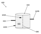
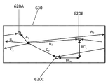
도 6a는 개시된 실시예 중 하나 이상에 따른 용기 체적 교정 시스템(600)의 예시적인 구성을 도시하고 있다. 시스템(600)은 표면(655) 상의 각 위치에 배치된 변환기(630) 및 3개의 센서(620A, 620B 및 620C)를 포함한다. 도시된 바와 같이, 센서는, 이러한 특정 구성에서, 변환기의 높이와도 다른 용기 상의 상이한 각 높이에 배치된다.6A illustrates an example configuration of a vessel
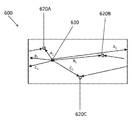
도 6b는 용기 벽(655)의 단순화된 2차원적인 "펼쳐진" 도면이다. 도 6b는, 벽이 도 6a에 도시된 가상의 분할 선(680)을 따라 절단되고 펼쳐지거나 편평한 것처럼, 용기 벽의 내면의 관점으로부터 도시되어 있다. 또한, 도 6b는 원점(즉, 변환기(630)의 위치)으로부터 센서를 향해 멀리 방사되는 음파에 의해 이동된 경로를 각각 도시하고 있다. 특히, 일반적으로 시계 방향으로 그리고 센서(620A, 620B 및 620C)를 향해 이동하는 음파의 경로는 각각 A1, B1, 및 C1으로 식별되고, 일반적으로 반시계 방향으로 이동하고 그리고 센서(620A, 620B 및 620C)를 향해 이동하는 음파의 경로는 각각 A2, B2, 및 C2로 식별된다.6B is a simplified two-dimensional “expanded” view of the
각 경로를 따라 이동하는 음파의 TOF 및 그 경로의 각 거리/길이는, 예를 들어 루틴(300)의 하나 이상의 단계에 따라 제어 컴퓨터(미도시)에 의해 계산될 수 있다. 또한, 용기의 둘레가 센서의 높이에 따라 변하지 않는다고 가정하면, 용기의 치수는, 예를 들어 다음 식의 시스템을 사용하여 수학적으로 계산될 수 있다:The TOF of the sound waves traveling along each path and each distance / length of the path may be calculated by a control computer (not shown), for example, in accordance with one or more steps of

전술한 솔루션을 사용한 계산은 둘 이상의 음향 장치 간의 기지의 위치 기반 관계를 요구할 수 있다. 예를 들어, 상기 기지의 관계는 2개의 음향 장치(예를 들어, 센서(620A) 및 변환기(630)) 간의 기지의 또는 독립적으로 측정된 거리일 수 있다. 일부 구현예에서, 기지의 관계는 종 방향 및/또는 횡 방향으로 표면 상의 적어도 2개의 음향 장치의 기지의 정렬일 수 있다. 또한, 용기 치수의 계산은, 당업자에 의해 이해될 수 있는 바와 같이, 추가적인 가정, 예를 들어 용기의 일정한 높이, 원통형 형상, 일정한 곡률 반경 등에 기초할 수 있다.Calculations using the solutions described above may require a known location based relationship between two or more acoustic devices. For example, the known relationship may be a known or independently measured distance between two acoustic devices (eg,
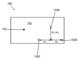
도 6c는 도 6a의 용기 체적 교정 시스템(600)의 측면도이고, 음향 변환기(630)는 종 방향으로 벽에서 상방 또는 하방으로 이동하도록 구성된다. 예를 들어, 변환기(630)는 제어 컴퓨터(110)(미도시)를 사용하여 제어될 수 있는 로봇(미도시)에 장착되어 음향 용기 체적 교정 공정 시 변환기(630)의 위치를 측정 가능하게 조정할 수 있다.FIG. 6C is a side view of the vessel
전술한 바와 같이, 변환기를 하나 이상의 음향 센서와 함께 종 방향 정렬로(즉, 같은 높이로 추정되는 원통형 용기 상의 동일한 종 방향 높이에) 위치 결정하면 정렬된 장치의 해당 높이에서 용기의 둘레를 정확하게 계산할 수 있다. 따라서, 하나 이상의 예시적인 실시예에서, 시스템은 (예를 들어, 로봇을 사용하여) 용기(650)의 벽(655)을 따라 종 방향으로 변환기(630)를 체계적으로 이동시키도록 구성될 수 있고, 변환기가 하나 이상의 센서와 같은 높이인 각 위치에 대해, 용기의 둘레가, 예를 들어 전술한 루틴(300)의 하나 이상의 단계에 따라 측정될 수 있다. 따라서, 상이한 높이에 위치된 다수의 센서를 포함하는 구성에서, 용기 둘레는 각 센서의 높이에서 결정될 수 있고, 궁극적으로 용기의 체적은 둘레의 임의의 높이 의존적 변화를 고려하여 보다 정확하게 계산될 수 있다. 추가 높이에서 용기의 둘레를 용이하게 측정하기 위해 음향 센서의 위치는 종 방향으로 유사하게 조정될 수 있음을 이해해야 한다.As noted above, positioning the transducer with one or more acoustic sensors in longitudinal alignment (ie, at the same longitudinal height on a cylindrical vessel presumed to be the same height) will accurately calculate the perimeter of the vessel at that height of the aligned device. Can be. Thus, in one or more illustrative embodiments, the system may be configured to systematically move the
개시된 실시예 중 하나 이상에 따르면, 용기 체적 교정 시스템은 용기의 원주 벽에 대해 하나 이상의 방향으로 둘 이상의 음향 장치를 자동 정렬하도록 구성될 수 있다. 정렬은 음향 기반 측정을 이용하여, 보다 구체적으로, 특정 장치 간의 계산된 음향 신호의 TOF에 기초하여 달성될 수 있다. 일반적으로, 장치가 정렬되어 있는 지를 검증하는 단계는 용기의 표면 상의 하나 이상의 음향 장치의 위치를 하나 이상의 횡 방향 및 종 방향으로 반복해서 조정하는 단계, 및 각 위치에 대해, 하나 이상의 재계산된 TOF가 적어도 2개의 음향 장치의 각 위치가 정렬된 것을 나타낼 때까지 TOF를 생성, 검출 및 계산하는 단계를 반복하는 단계를 포함할 수 있다.According to one or more of the disclosed embodiments, the vessel volume correction system may be configured to automatically align two or more acoustic devices in one or more directions with respect to the circumferential wall of the vessel. Alignment may be achieved using acoustic based measurements, more specifically based on the TOF of the calculated acoustic signal between specific devices. In general, verifying that the device is aligned includes repeatedly adjusting the position of one or more acoustic devices on the surface of the container in one or more transverse and longitudinal directions, and for each location, one or more recalculated TOFs. And repeating generating, detecting, and calculating TOF until s indicates that each position of the at least two acoustic devices is aligned.
보다 구체적으로, 일례로 비제한적으로, 예를 들어 제한 없이, 위치 제어 모듈(276)을 포함하는 하나 이상의 소프트웨어 모듈(230)을 실행함으로써 구성된 제어 컴퓨터(110)는 로봇을 사용하여 용기의 표면을 따라 종 방향으로 측정된 양만큼 변환기(630)를 위치시키고 재배치시킬 수 있다. 용기 표면에서 하나 이상의 방향으로 측정된 양만큼 변환기를 이동시키는 것은, 예를 들어 절대 위치 또는 상대 위치 및 로봇의 이동을 측정하기에 적합한 로봇에 탑재된 하나 이상의 센서(예를 들어, GPS 센서, 가속도계, 고도 센서 등)를 사용하여, 거의 실시간으로 수집된 위치 측정에 기초하여 제어될 수 있다. 로봇 및 그에 따른 변환기의 각각의 새로운 위치에 대해, 제어 컴퓨터는 변환기를 사용하여 하나 이상의 음향 펄스를 생성하는 단계, 하나 이상의 센서를 사용하여 표면을 따라 이동하는 음파를 검출하는 단계, 및 하나 이상의 펄스에 대해 TOF를 계산하는 단계를 수행할 수 있다. 바람직하게는, 변환기를 특정 센서, 예를 들어 센서(620A)와 정렬하려고 시도하면, TOF는 특정 센서(620A)에 의해 검출된 음파에 대해 계산된다. 변환기와 특정 센서 사이에서 이동하는 음파의 TOF는 거리에 정비례하기 때문에, 그 사이에서 이동하는 펄스에 대한 최소 값의 TOF가 식별될 때까지 변환기를 반복해서 이동시킴으로써 정렬이 달성된다. 언급된 바와 같이, 제어 컴퓨터는 변환기 또는 다른 음향 장치를 용기로부터 분리하고, 로봇을 재배치한 다음, 음향 장치를 새로운 위치에서 용기와 다시 치합하게 배치하도록 구성될 수 있다.More specifically, by way of example and not limitation,
도 6d는 변환기와 센서(620A)를 정렬하는 전체적인 과정을 통해 (벽이 도 6a에 도시된 가상의 분할 선(680)을 따라 절단되고 펼쳐진/편평한 것처럼) 벽의 내면의 관점에서 용기 벽(655)의 단면의 2차원적인 "펼쳐진" 도면이다. 도 6d는 정렬 공정 시 변환기(P1-P4)의 다중 위치, 및 각 변환기 위치에 대해, 변환기로부터 센서의 정지 위치 "A"로 음파에 의해 이동된 해당 경로를 도시하고 있다. 도 6d에 도시된 바와 같이, 변환기의 위치 P4와 센서 위치 A 사이의 경로 A1 및 A2가 가장 짧으므로, 위치 P4는 변환기가 위치 A를 갖는 센서와 정렬되는 변환기 위치인 것으로 결정될 수 있다. 도 6d는 일련의 수직 변환기(또는 로봇에 장착된 가동 변환기)가 각각의 장치 위치 간의 거리에 대한 솔루션을 야기할 수 있는 다중 경로를 생성함으로써 추가 정보를 제공할 수 있는 방법을 도 도시하고 있다. 구체적으로, 수평 라인 A1 및 A2는 센서 A에서 용기 둘레를 결정할 수 있기 때문에 중요하며, 이는 (수평 방향으로) 로봇/변환기 라인에 대해 탱크 상에 그 센서의 배치를 또한 제공하고, 이에 따라 연립 방정식의 해를 구할 수 있다.FIG. 6D illustrates the
도 6b와 같이, 도 6e는 용기 벽(655)의 2차원적인 "펼쳐진" 도면이며, 변환기(630)로부터 시스템(600)의 각 센서를 향해 멀리 방사되는 음파에 의해 이동된 경로를 도시하고 있다. 또한, 도 6e는 두 센서 사이 (또는 변환기와 하나의 센서 사이)의 기지의 거리가 연립 방정식을 해결하고 및/또는 재료에서 음속을 교정하는 데 도움이 되는 방법을 도시하고 있다. 이해할 수 있는 바와 같이, 용기 체적 교정 시스템의 교정은 결과적으로 용기 체적 측정의 정확도를 증가시킬 수 있다. 일부 구현예에서, 표면을 따라 또는 최단 경로를 따라 종 방향 및 횡 방향(x, y)으로 센서 간의 거리를 측정함으로써 교정이 달성될 수 있다. 예를 들어, 도 6e에 도시된 바와 같이, BCx 및 BCy가 측정되거나 알려진 경우, 다음 식은 참이다: By-Cy=BCy 및 Bx-Cx=BCx. 따라서, 다음과 같은 세트의 식은(이전에도 제공됨):As shown in FIG. 6B, FIG. 6E is a two-dimensional " expanded " view of the

해결될 수 있으며 또한 가정을 검증하기 위해 음속을 계산할 것이다. 전술한 바와 같이, 전술한 예시적인 연립 방정식은 용기가 그 높이 전체에 걸쳐 동일한 둘레를 갖는다는 가정에 기초하여 단순화된다.It can be solved and will also calculate the speed of sound to verify the hypothesis. As mentioned above, the exemplary simultaneous equations described above are simplified based on the assumption that the vessel has the same perimeter throughout its height.
하나 이상의 예시적인 실시예에서, 기지의 분리를 갖는 2개 이상의 센서로 구성된 용기 체적 교정 시스템은 교정의 정확성을 향상시키는 데 사용될 수 있다. 예를 들어, 도 7은 예시적인 용기 벽(755) 및 변환기(730)와 센서(720A, 720B 및 720C)를 포함하는 용기 체적 교정 시스템(700)의 2차원적인 "펼쳐진" 도면이다. 도 7은 두 센서 사이 (또는 변환기와 하나의 센서 사이)의 기지의 거리가 연립 방정식을 해결하고 및/또는 재료에서 음속을 교정하는 데 도움이 되는 방법을 도시하고 있다. 도 7에 도시된 특정 구성에서, 센서(720A)는 BCy=BAy 및 BCx=BAx 및 종 방향 및 횡 방향 거리가 서로 동일한 방식으로 용기의 벽에 부착된다.In one or more exemplary embodiments, a vessel volume calibration system consisting of two or more sensors with known separation can be used to improve the accuracy of the calibration. For example, FIG. 7 is a two-dimensional " expanded " view of a vessel
모든 센서가 이러한 예시적인 방식으로 그룹화되면, 바운싱 또는 다른 현상으로 인한 노이즈가 최소화될 수 있다. 또한, 시스템(700)은 그 자체를 교정하도록 구성될 수 있고, 센서 배치는 임의의 임펄스가 생성되는 방향을 계산하는 데 사용될 수 있다. 예를 들어, 파동의 방향성은 센서 간의 기지의 거리를 사용하여 계산될 수 있고, 이는 탱크 벽의 상부 및 하부 에지로부터 반사되는 것과 같은 바람직하지 않은 방향으로부터 전파되는 임의의 파동을 무시하는 데 사용될 수 있다. 음속에 대한 자체 교정은 기지의 간격을 갖는 두 센서 간의 TOF와 파동 전파 방향을 고려하여 수행될 수도 있다. 이러한 추가 정보는 제어 컴퓨터(110)에 의해 용기 기하학적 구조의 계산을 추가로 알릴 수 있고, 예를 들어 불량 데이터를 제거하고 선택적으로 국부적인 음속 측정을 제공함으로써 용기의 체적을 보다 정확하게 결정하는 데 사용될 수 있다.If all sensors are grouped in this exemplary manner, noise due to bouncing or other phenomena can be minimized. In addition, the
용기 체적 교정 시스템(800)의 예시적인 구성은 도 8에 도시되어 있는데, 도 8은 원통형 저장 용기의 벽(855)의 "펼쳐진" 2차원 도면이다. 도시된 바와 같이, 시스템(800)은 센서 세트가 둘레가 계산될 벽 상의 각 높이에 제공되도록 배치된 센서의 두 종 방향 행(행(825 및 820))을 포함한다. 시스템(800)은 하나 이상의 이동식 임펄스 발생기를 포함할 수도 있다. 일부 구성에서, 변환기(들)는 다양한 레벨에서 용기 둘레를 측정하기 위한 위치로 이동될 수 있도록 이동식 구성(예를 들어, 로봇에 장착됨)을 가질 수 있다. 도 8에 도시된 시스템(800)의 특정 구성에서, 복수의 변환기를 포함하는 종 방향 스트립(850)이 종 방향으로 벽에 장착된다. 작동 시, 각각의 높이에서의 센서는 임펄스를 수신할 수 있고, 제어 장치(110, 미도시)는 센서 간의 기지의 종 방향 거리(y)를 사용하여 변환기(들)와 센서 간의 임의의 오정렬을 보상할 수 있다. 예를 들어, 이러한 보상은 적용에 필요한 정확도에 따라 충분히 정확할 수 있는 작은 높이 차이 이상의 평균 둘레를 결정하는 것을 포함할 수 있다. 추가로 또는 대안적으로, 다음 측정으로 진행하기 전에, 전술한 바와 같이, 하나 이상의 센서와의 적절한 종 방향 정렬이 달성될 때까지 하나 이상의 변환기의 높이는 종 방향으로 조정될 수 있다.An exemplary configuration of the vessel
용기 체적 교정 시스템(900)의 예시적인 구성이 도 9에 도시되어 있는데, 도 9는 원통형 저장 용기의 벽(955)의 "펼쳐진" 2차원 도면이다. 시스템(900)은, 예를 들어 센서의 장기 설치일 수 있다. 도시된 바와 같이, 시스템(900)은 수평 방향으로 기지의 거리(x)만큼 이격된 센서의 두 종 방향 행을 각각 포함하는 두 세트인 "스트립"(925 및 920)을 포함한다. 따라서, 각 스트립은 둘레가 계산될 벽 상의 각 높이에 2개의 센서가 제공되도록 배치된다. 또한, 센서는 종 방향으로 기지의 거리(y)만큼 이격된다. 도시된 바와 같이, 시스템(900)은 임펄스 발생기(930)를 포함하기도 한다.An exemplary configuration of the vessel
도 9에 도시된 센서의 예시적인 구성은 증가된 정확도로 및/또는 변환기를 이동시킬 필요성을 제거하기 위해 둘레를 용이하게 결정할 수 있다. 예를 들어, 이동식 변환기를 사용하여 높은 정확도와 달리, 단일의 고정 임펄스 발생기를 갖는 것이 바람직한 경우, 3차원 공간에서 각 센서의 위치를 결정한 후에 변환기와 동일한 레벨을 갖는 2개의 센서를 사용하여 둘레의 측정이 도출되어 그 레벨에서 용기의 직경을 계산할 수 있다. 따라서, 제어 컴퓨터는, 단일 펄스를 사용하여, 한 쌍의 대향 센서를 포함하는 각 레벨의 직경을 계산하고, 이에 따라 용기의 해당 둘레 및/또는 총 체적을 결정하도록 구성될 수 있다. 이러한 예시적인 시스템 구성은 빈번한 모니터링이 필요한 경우에 유리할 수 있다. 더욱이, 두 세트의 센서가 용기의 대략 대향 측면에 위치되도록 (예를 들어, 시계 방향과 반시계 방향 양자로 원통형 용기에 대해 920과 926 사이에 일반적으로 동일한 원주 거리를 갖도록) 그 센서를 표면(955) 상에 배치함으로써 용기 기하학적 구조의 계산이 더욱 단순화될 수 있다는 점에 주목할 가치가 있다.The exemplary configuration of the sensor shown in FIG. 9 can easily determine the circumference with increased accuracy and / or to eliminate the need to move the transducer. For example, in contrast to high accuracy using mobile transducers, where it is desirable to have a single fixed impulse generator, after positioning each sensor in three-dimensional space, two sensors having the same level as the transducer A measurement can be derived to calculate the diameter of the vessel at that level. Thus, the control computer can be configured to calculate the diameter of each level comprising a pair of opposing sensors using a single pulse and thus determine the corresponding circumference and / or total volume of the vessel. This exemplary system configuration can be advantageous when frequent monitoring is required. Furthermore, the two sets of sensors are positioned on approximately opposite sides of the vessel (e.g., generally having the same circumferential distance between 920 and 926 for a cylindrical vessel in both clockwise and counterclockwise directions). It is worth noting that the calculation of the vessel geometry can be further simplified by placing on 955.
이러한 시점에서, 전술한 설명 중 많은 부분은 저장 용기의 체적을 교정하기 위한 시스템 및 방법에 관한 것이지만, 본 명세서에 개시된 시스템 및 방법은 시나리오, 상황, 참조된 시나리오를 넘는 설정으로 유사하게 배치되고 및/또는 구현될 수 있다. 예를 들어, 예시적인 시스템 및 방법은 다양한 유형의 기계적 파동을 사용하고 음향 장치에 제한 없이 용기의 체적을 측정하도록 구성될 수 있다.At this point, many of the foregoing descriptions relate to systems and methods for calibrating the volume of a storage container, although the systems and methods disclosed herein are similarly arranged in scenarios, situations, settings beyond the referenced scenarios, and And / or may be implemented. For example, the exemplary systems and methods can be configured to use various types of mechanical waves and to measure the volume of the vessel without limitation to the acoustic device.
도면에 도시되고 설명된 것보다 더 많거나 적은 작업이 수행될 수 있음을 이해해야 한다. 이러한 작업은 설명된 것과 다른 순서로 수행될 수도 있다. 도면에서 유사한 부호는 여러 도면을 통해 유사한 요소를 나타내고, 도면을 참조하여 설명되고 도시된 모든 구성요소 및/또는 단계가 모든 실시예 또는 배치에 필요한 것은 아니라는 것을 이해해야 한다.It should be understood that more or less work may be performed than shown and described in the drawings. Such operations may be performed in a different order than described. Like numbers in the drawings represent like elements throughout, and it should be understood that not all components and / or steps described and illustrated with reference to the drawings may be required in all embodiments or arrangements.
따라서, 본 시스템 및 방법의 예시적인 실시예 및 배치는 저장 용기의 체적을 교정하기 위한 시스템 및 컴퓨터 구현 방법, 컴퓨터 시스템, 및 컴퓨터 프로그램 제품을 제공한다. 도면의 흐름도 및 블록도는 다양한 실시예 및 배치에 따른 시스템, 방법 및 컴퓨터 프로그램 제품의 가능한 구현예의 구조, 기능 및 동작을 도시하고 있다. 이와 관련하여, 흐름도 또는 블록도의 각 블록은 특정된 논리 기능(들)을 구현하기 위한 하나 이상의 실행 가능한 명령을 포함하는 모듈, 세그먼트, 또는 코드의 일부를 나타낼 수 있다. 일부 대안적인 구현예에서, 블록에서 언급된 기능은 도면에서 언급된 순서를 벗어나서 일어날 수 있음을 유의해야 한다. 예를 들어, 연속으로 도시된 2개의 블록은 실제로 실질적으로 동시에 실행될 수 있거나, 또는 관련된 기능에 따라 블록이 때때로 역순으로 실행될 수 있다. 또한, 블록도 및/또는 흐름도의 각 블록 및 블록도 및/또는 흐름도의 블록의 조합은 특정 기능이나 동작, 또는 특수 목적 하드웨어 및 컴퓨터 명령의 조합을 수행하는 특수 목적의 하드웨어 기반 시스템에 의해 구현될 수 있다.Accordingly, exemplary embodiments and arrangements of the present systems and methods provide systems and computer implemented methods, computer systems, and computer program products for calibrating the volume of a storage container. The flow diagrams and block diagrams of the drawings illustrate the structure, function, and operation of possible implementations of systems, methods, and computer program products according to various embodiments and arrangements. In this regard, each block in the flowchart or block diagram may represent a module, segment, or portion of code that includes one or more executable instructions for implementing a specified logical function (s). In some alternative implementations, it should be noted that the functions noted in the blocks may occur out of the order noted in the figures. For example, two blocks shown in succession may actually be executed substantially concurrently, or blocks may sometimes be executed in reverse order, depending on the functionality involved. In addition, each block of the block diagrams and / or flowcharts and combinations of blocks in the block diagrams and / or flowcharts may be implemented by special purpose hardware-based systems that perform particular functions or operations or combinations of special purpose hardware and computer instructions. Can be.
본 명세서에서 사용된 용어는 단지 특정 실시예를 설명하기 위해 사용된 것으로, 본 발명을 한정하려는 의도가 아니다. 단수의 표현은 문맥 상 명백하게 다르게 뜻하지 않는 한, 복수의 표현을 포함한다. 본 명세서에서 사용될 때 "포함한다" 및/또는 "포함하는" 이라는 용어는 언급된 특징, 정수, 단계, 연산, 요소 및/또는 구성요소의 존재를 명시하지만, 하나 이상의 다른 특징, 정수, 단계, 연산, 요소, 구성요소 및/또는 이들의 그룹의 존재나 추가를 배제하지는 않는 것으로 더 이해될 것이다.The terminology used herein is for the purpose of describing particular embodiments only and is not intended to be limiting of the invention. Singular expressions include plural expressions unless the context clearly indicates otherwise. As used herein, the terms "comprises" and / or "comprising" specify the presence of a feature, integer, step, operation, element, and / or component that is mentioned, but one or more other features, integers, steps, It will be further understood that it does not exclude the presence or addition of operations, elements, components and / or groups thereof.
또한, 본 명세서에서 사용된 어구 및 용어는 설명을 위한 것으로 제한적인 것으로 간주되어서는 안된다. 본 명세서에서 "포함하는", "포함하는" 또는 "갖는", "함유하는", "포함하는" 및 그 변형의 사용은 그 이후에 열거된 항목 및 그의 등가물뿐만 아니라 추가 항목을 포함하는 것으로 의도된다.Also, the phraseology and terminology used herein is for the purpose of description and should not be regarded as limiting. The use of “comprising”, “comprising” or “having”, “comprising”, “comprising” and variations thereof herein is intended to include additional items as well as the items listed thereafter and their equivalents. do.
전술한 주제는 단지 예시를 위해 제공되며 제한적인 것으로 해석되어서는 안된다. 도시되고 설명된 예시적인 실시예 및 적용예를 따르지 않고, 다음의 청구 범위에 제시된 본 개시물의 진정한 사상 및 범위를 벗어남이 없이 본 명세서에 기술된 주제에 대해 다양한 수정 및 변경이 이루어질 수 있다.The foregoing subject matter is provided for illustrative purposes only and should not be construed as limiting. Various modifications and changes may be made to the subject matter described herein without departing from the illustrative embodiments and applications shown and described, without departing from the true spirit and scope of the disclosure as set forth in the following claims.
Claims (18)
상기 용기의 원주 벽의 외면 상의 각 위치에 상기 복수의 음향 장치를 배치하는 단계로서, 상기 하나 이상의 센서는 상기 표면에 음향적으로 결합되며 상기 표면을 따라 전파되는 펄스를 검출하도록 구성되고, 상기 변환기는 상기 표면에 음향적으로 결합되며 적어도 제1 원주 경로 및 제2 원주 경로에서 상기 변환기로부터 멀어지고 상기 하나 이상의 센서를 향해 상기 표면을 따라 방사되는 하나 이상의 펄스를 생성하도록 구성되는, 단계;
상기 변환기를 사용하여 하나 이상의 펄스를 생성하는 단계로서, 각 펄스는 임펄스 시간에 생성되는, 단계;
상기 하나 이상의 센서를 사용하여, 상기 제1 원주 경로 및 제2 원주 경로를 따라 방사되는 상기 하나 이상의 펄스를 검출하고, 각 원주 경로를 따라 방사되는 상기 하나 이상의 펄스가 검출되는 각 시간을 기록하는 단계;
상기 하나 이상의 센서와 전자 통신하는 컴퓨팅 장치에 의해, 상기 임펄스 시간 및 각 검출 시간에 기초하여, 상기 하나 이상의 펄스에 대한 각 비행 시간(TOF)을 계산하는 단계로서, 각 TOF는 상기 음향 장치들 중 2 개의 음향 장치 사이에서 특정 원주 경로를 따라 상기 펄스가 이동하는 경과 시간인, 단계;
상기 컴퓨팅 장치로, 상기 각 TOF 및 상기 벽을 통한 음속에 기초하여 상기 제1 및 제2 원주 방향의 각각에서 상기 음향 장치 간의 각 거리를 계산하는 단계; 및
상기 컴퓨팅 장치로, 상기 계산된 각 거리에 기초하여 상기 저장 용기의 체적을 결정하는 단계를 포함하는, 저장 용기의 체적을 측정하는 방법.A method of measuring the volume of a storage vessel using a plurality of acoustic devices including a transducer and one or more sensors, the method comprising:
Placing the plurality of acoustic devices at respective locations on the outer surface of the circumferential wall of the vessel, wherein the one or more sensors are configured to detect pulses acoustically coupled to the surface and propagating along the surface, the transducer Is acoustically coupled to the surface and configured to generate one or more pulses away from the transducer in at least a first circumferential path and a second circumferential path and emitted along the surface toward the one or more sensors;
Generating one or more pulses using the transducer, each pulse being generated at an impulse time;
Using the one or more sensors, detecting the one or more pulses emitted along the first and second circumferential paths and recording each time the one or more pulses emitted along each circumferential path are detected ;
Calculating, by the computing device in electronic communication with the one or more sensors, each flight time (TOF) for the one or more pulses, based on the impulse time and each detection time, wherein each TOF is one of the acoustic devices. The elapsed time that the pulse travels along a specific circumferential path between two acoustic devices;
Calculating, with the computing device, an angular distance between the acoustic devices in each of the first and second circumferential directions based on the respective sound velocity through the TOF and the wall; And
Determining, with the computing device, the volume of the storage container based on the calculated angular distances.
상기 컴퓨팅 장치로, 상기 기지의 분리 거리를 갖는 상기 제1 음향 센서와 제2 음향 센서 사이에서 방사되는 상기 펄스에 대한 TOF를 계산하는 단계; 및
상기 컴퓨팅 장치로, 상기 제1 음향 센서와 제2 음향 센서 사이에서 방사되는 펄스의 TOF 및 기지의 분리 거리에 기초하여 상기 벽을 통한 음속을 계산하는 단계를 더 포함하는, 저장 용기의 체적을 측정하는 방법.The method of claim 1, wherein disposing the plurality of acoustic devices comprises disposing at least a first acoustic sensor and a second acoustic sensor at each position separated by a known distance,
Calculating, with the computing device, a TOF for the pulse emitted between the first acoustic sensor and the second acoustic sensor having the known separation distance; And
Measuring, with the computing device, a volume of a storage container based on a TOF of a pulse emitted between the first acoustic sensor and a second acoustic sensor and a sound velocity through the wall based on a known separation distance. How to.
상기 계산된 TOF에 기초하여 상기 용기의 원주 벽에 대해 하나 이상의 횡 방향 및 종 방향으로 상기 음향 장치들 중 적어도 2개를 정렬하는 단계를 더 포함하는, 저장 용기의 체적을 측정하는 방법.The method of claim 1,
And aligning at least two of the acoustic devices in one or more transverse and longitudinal directions with respect to the circumferential wall of the vessel based on the calculated TOF.
상기 하나 이상의 횡 방향 및 종 방향으로 상기 표면 상에서 상기 음향 장치들 중 하나 이상의 각 위치를 반복해서 조정하는 단계; 및
상기 음향 장치들 중 적어도 2개의 각 위치가 하나 이상의 횡 방향 및 종 방향으로 정렬됨을 하나 이상의 재계산된 TOF가 나타낼 때까지 TOF를 생성, 검출 및 계산하는 단계를 반복하는 단계를 포함하는, 저장 용기의 체적을 측정하는 방법.The method of claim 3, wherein the aligning step,
Repeatedly adjusting each position of one or more of the acoustic devices on the surface in the one or more transverse and longitudinal directions; And
Generating, detecting and calculating a TOF until one or more recalculated TOFs indicate that each position of at least two of the acoustic devices is aligned in one or more transverse and longitudinal directions. How to measure the volume of the.
상기 컴퓨팅 장치 및 로봇을 사용하여 상기 변환기를 종 방향으로 소정 량 이동시키는 단계를 포함하되, 상기 변환기의 각 위치 및 상기 소정 량은 상기 로봇에 탑재된 하나 이상의 위치 센서를 사용하여 거의 실시간으로 측정되는, 저장 용기의 체적을 측정하는 방법.The method of claim 4, wherein repeatedly adjusting each position of one or more of the acoustic devices includes:
Moving the transducer in a longitudinal direction using the computing device and the robot, wherein each position and the quantity of the transducer are measured in near real time using one or more position sensors mounted on the robot. , Method of measuring the volume of a storage container.
상기 용기의 표면 상의 상이한 각 높이에 상기 복수의 센서를 배치하는 단계;
로봇을 사용하여 상기 용기의 표면을 따라 상기 종 방향으로 상기 변환기를 점진적으로 재배치하는 단계;
상기 변환기의 각 위치에 대해 상기 하나 이상의 펄스에 대한 TOF를 생성, 검출 및 계산하는 단계를 반복하는 단계;
상기 계산된 TOF에 기초하여, 상기 변환기가 상기 종 방향으로 상기 센서 중 하나 이상과 정렬되는 지를 결정하는 단계; 및
상기 계산된 TOF에 기초하여, 상기 변환기가 상기 복수의 센서 중 하나 이상과 정렬되는 것으로 결정되는 각 위치에서 상기 용기의 둘레를 계산하는 단계를 포함하는, 저장 용기의 체적을 측정하는 방법.The method of claim 1, wherein placing the plurality of sensors in each position on the surface of the container
Placing the plurality of sensors at different angular heights on the surface of the container;
Progressively relocating the transducer in the longitudinal direction along the surface of the vessel using a robot;
Repeating generating, detecting, and calculating a TOF for the one or more pulses for each position of the transducer;
Based on the calculated TOF, determining if the transducer is aligned with one or more of the sensors in the longitudinal direction; And
Based on the calculated TOF, calculating a circumference of the container at each location where the transducer is determined to be aligned with at least one of the plurality of sensors.
상기 용기의 원주 벽의 외면 상의 각 위치에 배치되도록 구성된 복수의 음향 장치로서,
상기 원주 벽에 음향적으로 결합되며 상기 표면을 따라 방사되는 펄스를 검출하도록 구성된 복수의 센서와,
상기 표면에 음향적으로 결합되며 각 원주 경로를 따라 상기 변환기로부터 멀어지고 상기 복수의 센서를 향해 상기 표면을 따라 방사되는 하나 이상의 펄스를 생성하도록 구성된 변환기를 포함하는, 복수의 음향 장치; 및
제어 컴퓨팅 시스템을 포함하되,
상기 제어 컴퓨팅 시스템은,
비일시적 컴퓨터 판독 가능 저장 매체,
상기 복수의 음향 장치, 상기 로봇 및 상기 컴퓨터 판독 가능 저장 매체와 전자 통신하는 하나 이상의 프로세서,
상기 저장 매체에 저장된 실행 가능 명령을 포함하는 하나 이상의 소프트웨어 모듈로서, 상기 하나 이상의 소프트웨어 모듈은 상기 프로세서에 의해 실행 가능한, 하나 이상의 소프트웨어 모듈을 포함하고,
상기 하나 이상의 소프트웨어 모듈은,
상기 변환기를 사용하여, 각 임펄스 시간에 상기 변환기를 사용하여 하나 이상의 펄스를 생성하도록 상기 프로세서를 구성하는 신호 제어 모듈로서, 상기 신호 제어 모듈은, 상기 센서를 사용하여, 상기 센서에 상기 하나 이상의 펄스의 도착을 각각 검출하고 각 검출 시간을 기록하도록 상기 프로세서를 더 구성하는, 신호 제어 모듈,
상기 각 임펄스 시간 및 각 검출 시간에 기초하여, 상기 하나 이상의 펄스에 대한 각 비행 시간(TOF)을 계산하도록 상기 프로세서를 구성하는 신호 분석 모듈로서, 각 TOF는 상기 음향 장치들 중 2 개의 음향 장치 사이에서 각 원주 경로를 따라 상기 펄스가 이동하는 경과 시간인, 신호 분석 모듈, 및
상기 각 TOF에 기초하여 상기 음향 장치 간의 거리 및 상기 벽을 통한 음속을 계산하고, 상기 계산된 거리에 기초하여 상기 저장 용기의 체적을 계산하도록 상기 프로세서를 구성하는 기하학적 분석 모듈을 포함하는, 저장 용기의 체적을 측정하기 위한 시스템.A system for measuring the volume of a storage container,
A plurality of acoustic devices configured to be disposed at respective positions on the outer surface of the circumferential wall of the container,
A plurality of sensors acoustically coupled to the circumferential wall and configured to detect pulses emitted along the surface;
A transducer, acoustically coupled to the surface, the transducer configured to generate one or more pulses away from the transducer along each circumferential path and emitted along the surface towards the plurality of sensors; And
Including a controlled computing system,
The control computing system,
Non-transitory computer readable storage media,
One or more processors in electronic communication with the plurality of acoustic devices, the robot and the computer readable storage medium,
One or more software modules including executable instructions stored on the storage medium, the one or more software modules including one or more software modules executable by the processor,
The one or more software modules,
A signal control module configured to use the transducer to configure the processor to generate one or more pulses using the transducer at each impulse time, wherein the signal control module uses the sensor to generate the one or more pulses to the sensor A signal control module, further configured to detect the arrival of each and record each detection time;
A signal analysis module that configures the processor to calculate each flight time (TOF) for the one or more pulses based on the respective impulse time and each detection time, each TOF being between two acoustic devices of the acoustic devices. A signal analysis module, wherein elapsed time the pulse travels along each circumferential path at
A geometric analysis module configured to calculate the distance between the acoustic devices and the speed of sound through the wall based on the respective TOFs, and to configure the processor to calculate the volume of the storage container based on the calculated distance. System for measuring the volume of the blood.
상기 원주 벽의 표면에 상기 음향 장치들 중 하나 이상을 배치하도록 구성된 로봇으로서, 상기 로봇은 구동 시스템 및 상기 로봇의 위치를 모니터링하기 위한 하나 이상의 위치 센서를 포함하고, 상기 로봇은 상기 표면에 상기 하나 이상의 음향 장치를 제어 가능하게 배치하도록 구성되는, 로봇; 및
상기 소프트웨어 모듈 중 위치 제어 모듈을 더 포함하되, 상기 위치 제어 모듈은, 상기 로봇을 사용하여, 상기 표면에서 상기 종 방향으로 상기 변환기의 각 위치를 반복해서 조정하고 상기 변환기가 상기 음향 센서들 중 적어도 하나와 상기 종 방향으로 정렬될 때까지 각 TOF를 재계산하도록 상기 프로세서를 구성하고, 상기 변환기와 상기 적어도 하나의 센서 사이에서 이동하는 펄스의 최소 재계산된 TOF가 상기 프로세서에 의해 식별될 때 정렬이 달성되는, 저장 용기의 체적을 측정하기 위한 시스템.The method of claim 8,
A robot configured to place one or more of the acoustic devices on a surface of the circumferential wall, the robot including a drive system and one or more position sensors for monitoring the position of the robot, the robot on the surface of the one A robot configured to controllably arrange the above acoustic devices; And
Further comprising a position control module of the software module, wherein the position control module, using the robot, repeatedly adjusts each position of the transducer in the longitudinal direction at the surface and the transducer is configured to perform at least one of the acoustic sensors. Configure the processor to recalculate each TOF until one and the longitudinal alignment, and align when a minimum recalculated TOF of pulses traveling between the transducer and the at least one sensor is identified by the processor. This is achieved, a system for measuring the volume of a storage container.
음향 센서의 어레이를 더 포함하되, 상기 어레이는 음향 센서의 적어도 2개의 평행한 종 방향 행을 포함하고, 종 방향 행의 상기 음향 센서는 기지의 종 방향 간격만큼 이격되고, 상기 2개의 행은 기지의 횡 방향 간격만큼 횡 방향으로 이격된, 저장 용기의 체적을 측정하기 위한 시스템.The method of claim 10,
Further comprising an array of acoustic sensors, the array comprising at least two parallel longitudinal rows of acoustic sensors, wherein the acoustic sensors of the longitudinal rows are spaced apart by a known longitudinal interval, and the two rows are known A system for measuring a volume of a storage container spaced laterally by a transverse interval of.
상기 용기의 원주 벽의 외면 상의 각 위치에 배치되도록 구성된 복수의 음향 장치로서,
상기 원주 벽에 음향적으로 결합되며 상기 표면을 따라 방사되는 펄스를 검출하도록 구성된 복수의 센서와,
상기 표면에 음향적으로 결합되며 각 원주 경로를 따라 상기 변환기로부터 멀어지고 상기 복수의 센서를 향해 상기 표면을 따라 방사되는 하나 이상의 펄스를 생성하도록 구성된 변환기를 포함하는, 복수의 음향 장치;
상기 원주 벽의 표면에 상기 음향 장치들 중 하나 이상을 배치하도록 구성된 로봇으로서, 상기 로봇은 구동 시스템 및 상기 로봇의 위치를 모니터링하기 위한 하나 이상의 위치 센서를 포함하고, 상기 로봇은 상기 표면에 상기 하나 이상의 음향 장치를 제어 가능하게 배치하도록 구성되는, 로봇; 및
제어 컴퓨팅 시스템을 포함하되,
상기 제어 컴퓨팅 시스템은,
비일시적 컴퓨터 판독 가능 저장 매체,
상기 복수의 음향 장치, 상기 로봇 및 상기 컴퓨터 판독 가능 저장 매체와 전자 통신하는 하나 이상의 프로세서,
상기 저장 매체에 저장된 실행 가능 명령을 포함하는 하나 이상의 소프트웨어 모듈로서, 상기 하나 이상의 소프트웨어 모듈은 상기 프로세서에 의해 실행 가능한, 하나 이상의 소프트웨어 모듈을 포함하고,
상기 하나 이상의 소프트웨어 모듈은,
상기 변환기를 사용하여, 각 임펄스 시간에 상기 변환기를 사용하여 하나 이상의 펄스를 생성하도록 상기 프로세서를 구성하는 신호 제어 모듈로서, 상기 신호 제어 모듈은, 상기 센서를 사용하여, 상기 센서에 상기 하나 이상의 펄스의 도착을 각각 검출하고 각 검출 시간을 기록하도록 상기 프로세서를 더 구성하는, 신호 제어 모듈,
상기 각 임펄스 시간 및 각 검출 시간에 기초하여, 상기 하나 이상의 펄스에 대한 각 비행 시간(TOF)을 계산하도록 상기 프로세서를 구성하는 신호 분석 모듈로서, 각 TOF는 상기 음향 장치들 중 2 개의 음향 장치 사이에서 각 원주 경로를 따라 상기 펄스가 이동하는 경과 시간인, 신호 분석 모듈,
상기 각 TOF에 기초하여 상기 음향 장치 간의 거리 및 상기 벽을 통한 음속을 계산하고, 상기 계산된 거리에 기초하여 상기 저장 용기의 체적을 계산하도록 상기 프로세서를 구성하는 기하학적 분석 모듈, 및
상기 로봇을 사용하여, 상기 표면에서 상기 음향 장치들 중 하나 이상의 각 위치를 반복해서 조정하고 상기 음향 장치들 중 적어도 2개가 횡 방향 및 종 방향 중 하나로 정렬될 때까지 각 TOF를 재계산하도록 상기 프로세서를 구성하는 위치 제어 모듈을 포함하고, 상기 적어도 두 장치의 정렬은 상기 적어도 두 음향 장치 사이에서 방사되는 펄스의 상기 재계산된 TOF가 최소화될 때 달성되는, 저장 용기의 체적을 측정하기 위한 시스템.A system for measuring the volume of a storage container,
A plurality of acoustic devices configured to be disposed at respective positions on the outer surface of the circumferential wall of the container,
A plurality of sensors acoustically coupled to the circumferential wall and configured to detect pulses emitted along the surface;
A transducer, acoustically coupled to the surface, the transducer configured to generate one or more pulses away from the transducer along each circumferential path and emitted along the surface towards the plurality of sensors;
A robot configured to place one or more of the acoustic devices on a surface of the circumferential wall, the robot including a drive system and one or more position sensors for monitoring the position of the robot, the robot on the surface of the one A robot configured to controllably arrange the above acoustic devices; And
Including a controlled computing system,
The control computing system,
Non-transitory computer readable storage media,
One or more processors in electronic communication with the plurality of acoustic devices, the robot and the computer readable storage medium,
One or more software modules including executable instructions stored on the storage medium, the one or more software modules including one or more software modules executable by the processor,
The one or more software modules,
A signal control module configured to use the transducer to configure the processor to generate one or more pulses using the transducer at each impulse time, wherein the signal control module uses the sensor to generate the one or more pulses to the sensor A signal control module, further configured to detect the arrival of each and record each detection time;
A signal analysis module that configures the processor to calculate each flight time (TOF) for the one or more pulses based on the respective impulse time and each detection time, each TOF being between two acoustic devices of the acoustic devices. A signal analysis module, wherein elapsed time the pulse travels along each circumferential path at
A geometric analysis module configured to calculate the distance between the acoustic devices and the speed of sound through the wall based on the respective TOFs, and calculate the volume of the storage container based on the calculated distance, and
Using the robot, the processor repeatedly adjusts each position of one or more of the acoustic devices on the surface and recalculates each TOF until at least two of the acoustic devices are aligned in one of the transverse and longitudinal directions. And a position control module, wherein said alignment of said at least two devices is achieved when said recomputed TOF of pulses radiated between said at least two acoustic devices is minimized.
Applications Claiming Priority (3)
| Application Number | Priority Date | Filing Date | Title |
|---|---|---|---|
| US15/491,588 | 2017-04-19 | ||
| US15/491,588 US10480982B2 (en) | 2017-04-19 | 2017-04-19 | Acoustic calibration array for tanks and vessels |
| PCT/US2018/023316 WO2018194784A1 (en) | 2017-04-19 | 2018-03-20 | Acoustic calibration array for tanks and vessels |
Publications (1)
| Publication Number | Publication Date |
|---|---|
| KR20200003385A true KR20200003385A (en) | 2020-01-09 |
Family
ID=61913572
Family Applications (1)
| Application Number | Title | Priority Date | Filing Date |
|---|---|---|---|
| KR1020197033638A KR20200003385A (en) | 2017-04-19 | 2018-03-20 | Acoustic Calibration Arrays for Tanks and Vessels |
Country Status (8)
| Country | Link |
|---|---|
| US (2) | US10480982B2 (en) |
| EP (1) | EP3612830B1 (en) |
| JP (1) | JP6907448B2 (en) |
| KR (1) | KR20200003385A (en) |
| CN (1) | CN110520723A (en) |
| SA (1) | SA519410187B1 (en) |
| SG (1) | SG11201909387TA (en) |
| WO (1) | WO2018194784A1 (en) |
Families Citing this family (16)
| Publication number | Priority date | Publication date | Assignee | Title |
|---|---|---|---|---|
| US10480982B2 (en) * | 2017-04-19 | 2019-11-19 | Saudi Arabian Oil Company | Acoustic calibration array for tanks and vessels |
| US10458831B2 (en) * | 2017-07-05 | 2019-10-29 | Saudi Arabian Oil Company | System and method for acoustic container volume calibration |
| US11097796B2 (en) * | 2018-11-29 | 2021-08-24 | Saudi Arabian Oil Company | Articulated magnet-bearing legs for UAV landing on curved surfaces |
| US11231311B2 (en) | 2019-05-31 | 2022-01-25 | Perceptive Sensor Technologies Llc | Non-linear ultrasound method and apparatus for quantitative detection of materials |
| EP3822660A1 (en) | 2019-11-13 | 2021-05-19 | ABB Schweiz AG | Integrity detection system for an ultrasound transducer |
| WO2022120074A1 (en) | 2020-12-02 | 2022-06-09 | Perceptive Sensor Technologies Llc | Variable angle transducer interface block |
| CN116829915A (en) | 2020-12-04 | 2023-09-29 | 感知传感器技术股份有限公司 | Acoustic temperature measurement in a layered environment |
| US11549839B2 (en) | 2020-12-04 | 2023-01-10 | Perceptive Sensor Technologies, Inc. | Systems and methods for determining floating roof level tilt and characterizing runoff |
| US11604294B2 (en) | 2020-12-04 | 2023-03-14 | Perceptive Sensor Technologies, Inc. | Determining layer characteristics in multi-layered environments |
| US11536696B2 (en) | 2020-12-04 | 2022-12-27 | Perceptive Sensor Technologies, Inc. | In-wall multi-bounce material property detection and acoustic signal amplification |
| CA3201086A1 (en) | 2020-12-04 | 2022-06-09 | Lazar Bivolarsky | Apparatus, system, and method for the detection of objects and activity within a container |
| US11585690B2 (en) * | 2020-12-04 | 2023-02-21 | Perceptive Sensor Technologies, Inc. | Multi-path acoustic signal improvement for material detection |
| US11788904B2 (en) | 2020-12-04 | 2023-10-17 | Perceptive Sensor Technologies, Inc. | Acoustic temperature measurement in layered environments |
| WO2022147234A1 (en) | 2020-12-30 | 2022-07-07 | Perceptive Sensor Technologies, Inc. | Evaluation of fluid quality with signals |
| WO2023154514A1 (en) | 2022-02-11 | 2023-08-17 | Perceptive Sensor Technologies, Inc. | Acoustic signal detection of material composition in static and dynamic conditions |
| US11940420B2 (en) | 2022-07-19 | 2024-03-26 | Perceptive Sensor Technologies, Inc. | Acoustic signal material identification with nanotube couplant |
Family Cites Families (24)
| Publication number | Priority date | Publication date | Assignee | Title |
|---|---|---|---|---|
| US4748846A (en) * | 1982-10-14 | 1988-06-07 | Gilbarco, Inc. | Tank gauging system and methods |
| US4805453A (en) * | 1982-10-14 | 1989-02-21 | Gilbarco, Inc. | Tank sonic gauging system and methods |
| US5456114A (en) | 1993-04-23 | 1995-10-10 | Panametrics, Inc. | Elastic wave sensing system |
| US5765433A (en) * | 1995-03-10 | 1998-06-16 | Arizona Instrument Corporation | Liquid measuring system and methods |
| US6573732B1 (en) * | 1999-05-04 | 2003-06-03 | Ssi Technologies, Inc. | Dynamic range sensor and method of detecting near field echo signals |
| US6363788B1 (en) | 2000-06-07 | 2002-04-02 | Digital Wave Corporation | Noninvasive detection of corrosion, mic, and foreign objects in containers, using guided ultrasonic waves |
| US7216536B2 (en) | 2001-06-22 | 2007-05-15 | Young Manufacturing & Engineering, Inc. | Acoustic volume indicator |
| US6938488B2 (en) * | 2002-08-21 | 2005-09-06 | Battelle Memorial Institute | Acoustic inspection device |
| US6925870B2 (en) * | 2003-09-23 | 2005-08-09 | Battelle Memorial Institute | Ultrasonic fill level device and method |
| DE10348676A1 (en) * | 2003-10-15 | 2005-05-12 | Flowtec Ag | Device for determining and / or monitoring the volume and / or mass flow of a medium in a pipeline |
| EP1959229A1 (en) | 2007-02-19 | 2008-08-20 | Nederlandse Organisatie Voor Toegepast-Natuurwetenschappelijk Onderzoek Tno | Ultrasonic surface monitoring |
| US8806944B2 (en) * | 2009-09-18 | 2014-08-19 | Conocophillips Company | High precision ultrasonic corrosion rate monitoring |
| US20120281096A1 (en) * | 2011-05-02 | 2012-11-08 | Honeywell-Enraf B.V. | Storage tank inspection system and method |
| US9052230B2 (en) * | 2011-05-13 | 2015-06-09 | Chevron U.S.A. Inc | Industrial process monitoring and imaging |
| US9188472B2 (en) | 2013-05-21 | 2015-11-17 | Saudi Arabian Oil Company | Enhanced reference line tank calibration method and apparatus |
| GB2521661A (en) | 2013-12-27 | 2015-07-01 | Xsens As | Apparatus and method for measuring flow |
| US20160041024A1 (en) * | 2014-08-11 | 2016-02-11 | Ssi Technologies, Inc. | Through-wall tank ultrasonic transducer |
| US20160320226A1 (en) * | 2015-04-30 | 2016-11-03 | Siemens Industry, Inc. | Determining height of a liquid level interface in a container from acoustic signal or echo time measurement |
| EP3115753B1 (en) * | 2015-07-06 | 2022-01-05 | ABB Schweiz AG | System and method for non-intrusive and continuous level measurement of a liquid |
| US10571328B2 (en) * | 2015-08-29 | 2020-02-25 | Mopeka Products Llc | Sensor arrangements, sensor systems, and methods for determining height of liquids in tanks |
| JP7152951B2 (en) * | 2015-10-12 | 2022-10-13 | ラブサイト インコーポレイテッド | Systems and methods for marking containers and acoustically identifying container properties |
| UA122259C2 (en) * | 2016-01-18 | 2020-10-12 | Гевееф Месзюстеме Аг | Improved beam shaping acoustic signal travel time flow meter |
| US10480982B2 (en) * | 2017-04-19 | 2019-11-19 | Saudi Arabian Oil Company | Acoustic calibration array for tanks and vessels |
| US10458831B2 (en) * | 2017-07-05 | 2019-10-29 | Saudi Arabian Oil Company | System and method for acoustic container volume calibration |
-
2017
- 2017-04-19 US US15/491,588 patent/US10480982B2/en active Active
-
2018
- 2018-03-20 KR KR1020197033638A patent/KR20200003385A/en unknown
- 2018-03-20 JP JP2019556253A patent/JP6907448B2/en active Active
- 2018-03-20 SG SG11201909387T patent/SG11201909387TA/en unknown
- 2018-03-20 WO PCT/US2018/023316 patent/WO2018194784A1/en unknown
- 2018-03-20 EP EP18716746.5A patent/EP3612830B1/en active Active
- 2018-03-20 CN CN201880025188.1A patent/CN110520723A/en active Pending
-
2019
- 2019-08-09 US US16/537,246 patent/US10942054B2/en active Active
- 2019-09-24 SA SA519410187A patent/SA519410187B1/en unknown
Also Published As
| Publication number | Publication date |
|---|---|
| EP3612830A1 (en) | 2020-02-26 |
| EP3612830B1 (en) | 2022-03-02 |
| JP6907448B2 (en) | 2021-07-21 |
| WO2018194784A1 (en) | 2018-10-25 |
| US20180306628A1 (en) | 2018-10-25 |
| JP2020517918A (en) | 2020-06-18 |
| SA519410187B1 (en) | 2022-07-20 |
| US10942054B2 (en) | 2021-03-09 |
| US20190360850A1 (en) | 2019-11-28 |
| US10480982B2 (en) | 2019-11-19 |
| CN110520723A (en) | 2019-11-29 |
| SG11201909387TA (en) | 2019-11-28 |
Similar Documents
| Publication | Publication Date | Title |
|---|---|---|
| US10942054B2 (en) | Acoustic calibration array for tanks and vessels | |
| US10935408B2 (en) | System and method for acoustic container volume calibration | |
| US11035669B2 (en) | Tilt and distance profiling vehicle | |
| CN105388457A (en) | Long-baseline hydroacoustic positioning method based on equivalent acoustic velocity gradient | |
| MX2011010162A (en) | Processing seismic data. | |
| US8576657B1 (en) | Method for calibrating a plurality of data channels in a vector sensor | |
| Darmon et al. | Main features of a complete ultrasonic measurement model: Formal aspects of modeling of both transducers radiation and ultrasonic flaws responses | |
| RU2629896C1 (en) | Method of ultrasonic control of pipeline and system for its implementation | |
| Tabatabaeipour et al. | A feasibility study on guided wave-based robotic mapping | |
| CN109341819A (en) | Self-correction ultrasonic measuring device and its measurement method | |
| EP2477042A1 (en) | Method and device for measuring distance and orientation using a single electro-acoustic transducer | |
| US20200108501A1 (en) | Robotic Platforms and Robots for Nondestructive Testing Applications, Including Their Production and Use | |
| EP4170339A1 (en) | Ultrasonic inspection of complex surfaces | |
| Gao et al. | Underwater acoustic positioning system based on propagation loss and sensor network | |
| KR101757067B1 (en) | Apparatus and method for mesuring speed and distance using two sensor | |
| CN108982666A (en) | A kind of water logging ultrasonic non-destructive measurement method to hardened structure reflection/transmission coefficient | |
| RU2736231C1 (en) | Method for determining sound velocity distribution | |
| US9417311B2 (en) | Method and device for phase-based localization of a target device using interval analysis | |
| US20200139404A1 (en) | Rayleigh wave positioning system (raps) | |
| WO2024052847A1 (en) | Hybrid sensor head for surface inspection and method of use | |
| Zhang et al. | Autofocus imaging: Experimental results in an anisotropic austenitic weld |