KR20200000736U - Apparatus of insulation hanger for lightning arrester in power distribution - Google Patents
Apparatus of insulation hanger for lightning arrester in power distribution Download PDFInfo
- Publication number
- KR20200000736U KR20200000736U KR2020180004527U KR20180004527U KR20200000736U KR 20200000736 U KR20200000736 U KR 20200000736U KR 2020180004527 U KR2020180004527 U KR 2020180004527U KR 20180004527 U KR20180004527 U KR 20180004527U KR 20200000736 U KR20200000736 U KR 20200000736U
- Authority
- KR
- South Korea
- Prior art keywords
- arrester
- hanger
- insulation
- insulating
- bracket
- Prior art date
Links
Images


Classifications
-
- H—ELECTRICITY
- H02—GENERATION; CONVERSION OR DISTRIBUTION OF ELECTRIC POWER
- H02G—INSTALLATION OF ELECTRIC CABLES OR LINES, OR OF COMBINED OPTICAL AND ELECTRIC CABLES OR LINES
- H02G13/00—Installations of lightning conductors; Fastening thereof to supporting structure
- H02G13/80—Discharge by conduction or dissipation, e.g. rods, arresters, spark gaps
-
- H—ELECTRICITY
- H01—ELECTRIC ELEMENTS
- H01C—RESISTORS
- H01C7/00—Non-adjustable resistors formed as one or more layers or coatings; Non-adjustable resistors made from powdered conducting material or powdered semi-conducting material with or without insulating material
- H01C7/10—Non-adjustable resistors formed as one or more layers or coatings; Non-adjustable resistors made from powdered conducting material or powdered semi-conducting material with or without insulating material voltage responsive, i.e. varistors
- H01C7/12—Overvoltage protection resistors
Abstract
배전용 피뢰기의 절연 행거 장치에 관한 고안이 개시된다. 본 고안에 따른 배전용 피뢰기의 절연 행거 장치는: 피뢰기; 피뢰기가 장착되는 절연행거; 및 절연행거와 브래킷에 의해 연결되고, 지주에 고정되는 완철을 포함하고, 절연행거는, 피뢰기와 브래킷을 연결하는 절연행거 몸체부; 및 절연행거 몸체부의 길이방향을 따라 복수개가 돌출되게 장착되는 절연 갓부를 포함하는 것을 특징으로 한다.Disclosure of the invention An insulating hanger device for a distribution arrester is disclosed. The insulation hanger device of the lightning arrester according to the present invention includes: an arrester; An insulation hanger equipped with an arrester; And an insulated hanger connected by an insulated hanger and a bracket and fixed to a prop, the insulated hanger comprising: an insulated hanger body portion connecting the arrester and the bracket; And it characterized in that it comprises an insulating hanger portion is mounted a plurality of protrusions along the longitudinal direction of the insulating hanger body portion.
Description
본 고안은 배전용 피뢰기의 절연 행거 장치에 관한 것으로, 보다 상세하게는 전력계통에서 뇌 서지(lightning surge) 또는 개폐시 발생하는 이상 전압을 제한하고, 상용주파 속류를 차단하는 배전용 피뢰기의 절연 행거 장치에 관한 것이다.The present invention relates to an insulation hanger device for a distribution arrester, and more specifically, to limit an abnormal voltage generated during a lightning surge or opening and closing in a power system, and an insulation hanger for a distribution arrester that blocks the rapid flow of commercial frequency. It is about the device.
배전용 피뢰기는 뇌 서지 또는 개폐시 발생하는 이상전압을 대지로 흘려보내고 속류를 차단하는 설비로서, 주로 배전용변압기와 배전용개폐기를 보호하기 위해서 설치한다.The distribution arrester is a facility that flows abnormal voltages generated during brain surges or opening and closing to the ground and blocks the rapid flow, and is mainly installed to protect the distribution transformers and distribution switch.
종래 기술에서 배전용 피뢰기를 설치하기 위해서 피뢰기의 절연행거에 내오손 결합애자를 추가로 부설하여 피뢰기의 두부와 접지된 완철 간의 거리를 최대한 이격한다. 내오손 결합애자는 피뢰기의 두부와 접지된 완철 간의 거리를 물리적으로 증대하여 까치, 까마귀 등의 조류로 인한 고장을 최소화하기 위한 것이다. In order to install a lightning arrester for distribution in the prior art, a distance between the head of the arrester and the grounded iron rod is spaced as much as possible by additionally installing an antifouling coupling insulator on the insulation hanger of the arrester. The anti-fouling insulator is intended to minimize the failure caused by birds such as magpies and crows by physically increasing the distance between the head of the arrester and the grounded iron rod.
최근에는 리드선 부착형 피뢰기가 개발되어 두부의 금속체가 직접 노출되는 것을 구조적으로 막고 있기 때문에 순간 고장은 많이 감소되고 있다. 그러나 피뢰기의 1차 리드선이나 두부에 철사나 나뭇가지 등이 장시간 접촉하면 방전이 지속되어 고장을 유발할 수 있다. 그로 인해 현장에서는 고장을 예방하기 위하여 배전용 피뢰기 설치시 절연행거에 내오손 결합애자를 추가로 취부하고 있다.In recent years, lead-wire-type arresters have been developed and structurally prevent the direct exposure of the metal body of the head, so instantaneous failure is greatly reduced. However, if a wire or a tree branch is in contact with the primary lead wire or head of the arrester for a long time, discharge may continue and cause a malfunction. For this reason, in order to prevent failure, in the field, when the distribution arrester is installed, an anti-fouling insulator is additionally installed on the insulation hanger.
배전용 피뢰기 설치시 내오손 결합애자를 추가로 취부하는 것은 별도의 자재비와 시공비가 발생하는 경제적인 손실이 발생된다. 또한 제조시 소성 불량에 의해서 자기 재질의 내오손 결합애자가 파손되거나, 제조 결함에 의해서 폴리머 재질의 내오손 결합애자의 금구가 파손되는 문제가 있다. 따라서 이를 개선할 필요성이 요청된다.When installing a distribution arrester, installing additional anti-fouling insulators results in an economical loss of material and construction costs. In addition, there is a problem in that the bonding resistance insulator of the magnetic material is damaged due to the poor plasticity during manufacturing, or the metal fitting of the fouling resistance insulator of the polymer material is damaged due to the manufacturing defect. Therefore, there is a need to improve this.
본 고안의 배경기술은 대한민국 등록실용신안공보 제20-0482717호(2017.02.20 등록, 고안의 명칭: 친환경 리드선 일체형 피뢰기)에 개시되어 있다.Background art of this design is disclosed in Republic of Korea Utility Model Publication No. 20-0482717 (registered on February 20, 2017, name of design: environmentally friendly lead wire type arrester).
본 고안은 상기와 같은 문제점을 해결하기 위해 안출된 것으로, 전력계통에서 뇌 서지 또는 개폐시 발생하는 이상전압을 제한하고, 상용주파 속류를 차단하는 배전용 피뢰기의 절연 행거 장치를 제공하는 것이다.The present invention was devised to solve the above problems, and to provide an insulation hanger device for a distribution arrester that limits the abnormal voltage generated during brain surges or opening and closing in the power system and blocks the rapid flow of commercial frequencies.
본 고안에 따른 배전용 피뢰기의 절연 행거 장치는: 피뢰기; 상기 피뢰기가 장착되는 절연행거; 및 상기 절연행거와 브래킷에 의해 연결되고, 지주에 고정되는 완철을 포함하고, 상기 절연행거는, 상기 피뢰기와 상기 브래킷을 연결하는 절연행거 몸체부; 및 상기 절연행거 몸체부의 길이방향을 따라 복수개가 돌출되게 장착되는 절연 갓부를 포함한다.The insulation hanger device of the lightning arrester according to the present invention includes: an arrester; An insulation hanger to which the arrester is mounted; And it is connected by the insulating hanger and a bracket, and includes a solid iron fixed to the support, the insulating hanger, the insulating hanger body portion connecting the arrester and the bracket; And an insulating lampshade in which a plurality of the insulating hanger body portions are mounted to protrude along the longitudinal direction.
본 고안에서 상기 절연행거 몸체부는, 절연행거 메인몸체부; 상기 절연행거 메인몸체부의 일측에 형성되고, 상기 피뢰기가 장착되는 피뢰기 고정부; 및 상기 절연행거 메인몸체부의 타측에 형성되고, 상기 브래킷과 연결되는 브래킷 고정부를 포함한다.In the present invention, the insulating hanger body portion, the insulating hanger main body portion; An arrester fixing part formed on one side of the main body of the insulating hanger and equipped with the arrester; And a bracket fixing part formed on the other side of the main body of the insulating hanger and connected to the bracket.
본 고안에서 상기 절연행거 몸체부는, 상기 절연행거 메인몸체부와 상기 피뢰기 고정부, 또는 상기 절연행거 메인몸체부와 상기 브래킷 고정부 사이에 형성되는 보강부를 더 포함한다.In the present invention, the insulation hanger body part further includes a reinforcement part formed between the insulation hanger main body part and the arrester fixing part, or between the insulation hanger main body part and the bracket fixing part.
본 고안에서 상기 보강부는 상기 피뢰기 고정부 또는 상기 브래킷 고정부에서 상기 절연행거 메인몸체부 측을 향할수록 폭이 증가되게 형성된다.In the present invention, the reinforcing part is formed such that the width increases as it goes toward the side of the main body of the insulating hanger from the arrester fixing part or the bracket fixing part.
본 고안에서 상기 절연행거는 표면에 방수 수지가 도포된다.In the present invention, the insulating hanger is coated with a waterproof resin on the surface.
본 고안에 따른 뇌 서지 또는 개폐시 발생되는 이상 전압을 대지로 흘려 보내고 속류를 차단할 수 있다.According to the present invention, an abnormal voltage generated during a brain surge or opening and closing can be flowed to the ground and blocking the rapid flow.
또한 본 고안에 따르면 피뢰기의 취부시 별도의 내오손 결합애자를 필요로 하지 않고, 절연행거에 의해 피뢰기와 완철의 브래킷을 연결함으로써, 자재비를 절감하고 시공시간을 단축할 수 있다.In addition, according to the present invention, a separate anti-fouling coupling insulator is not required when the lightning arrester is mounted, and by connecting the lightning arrester and the bracket of the steel rod by an insulation hanger, material costs can be reduced and construction time can be shortened.
도 1은 본 고안의 일 실시예에 따른 배전용 피뢰기의 절연 행거 장치를 개략적으로 나타내는 개념도이다.
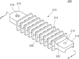
도 2는 본 고안의 일 실시예에 따른 절연행거를 개략적으로 나타내는 사시도이다.
도 3은 본 고안의 일 실시예에 따른 절연행거를 개략적으로 나타내는 단면도이다.
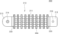
도 4는 본 고안의 일 실시예에 따른 절연행거를 개략적으로 나타내는 평면도이다.
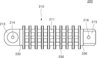
도 5는 본 고안의 일 실시예에 따른 절연행거를 개략적으로 나타내는 저면도이다.1 is a conceptual diagram schematically showing an insulating hanger device of a lightning arrester according to an embodiment of the present invention.
2 is a perspective view schematically showing an insulation hanger according to an embodiment of the present invention.
3 is a cross-sectional view schematically showing an insulation hanger according to an embodiment of the present invention.
4 is a plan view schematically showing an insulation hanger according to an embodiment of the present invention.
5 is a bottom view schematically showing an insulation hanger according to an embodiment of the present invention.
이하, 첨부된 도면들을 참조하여 본 고안에 따른 배전용 피뢰기의 절연 행거 장치의 일 실시예를 설명한다. 이러한 과정에서 도면에 도시된 선들의 두께나 구성요소의 크기 등은 설명의 명료성과 편의상 과장되게 도시되어 있을 수 있다. Hereinafter, an embodiment of an insulation hanger device for a lightning arrester according to the present invention will be described with reference to the accompanying drawings. In this process, the thickness of the lines or the size of components shown in the drawings may be exaggerated for clarity and convenience.
또한, 후술되는 용어들은 본 고안에서의 기능을 고려하여 정의된 용어들로써, 이는 사용자, 운용자의 의도 또는 관례에 따라 달라질 수 있다. 그러므로 이러한 용어들에 대한 정의는 본 명세서 전반에 걸친 내용을 토대로 내려져야 할 것이다.In addition, terms to be described later are terms defined in consideration of functions in the present invention, which may vary according to a user's or operator's intention or practice. Therefore, the definition of these terms should be made based on the contents throughout the present specification.
도 1은 본 고안의 일 실시예에 따른 배전용 피뢰기의 절연 행거 장치를 개략적으로 나타내는 개념도이고, 도 2는 본 고안의 일 실시예에 따른 절연행거를 개략적으로 나타내는 사시도이고, 도 3은 본 고안의 일 실시예에 따른 절연행거를 개략적으로 나타내는 단면도이고, 도 4는 본 고안의 일 실시예에 따른 절연행거를 개략적으로 나타내는 평면도이고, 도 5는 본 고안의 일 실시예에 따른 절연행거를 개략적으로 나타내는 저면도이다.1 is a conceptual diagram schematically showing an insulation hanger device of a distribution arrester according to an embodiment of the present invention, FIG. 2 is a perspective view schematically showing an insulation hanger according to an embodiment of the present invention, and FIG. 3 is the present invention 4 is a cross-sectional view schematically showing an insulation hanger according to an embodiment, FIG. 4 is a plan view schematically showing an insulation hanger according to an embodiment of the present invention, and FIG. 5 is a schematic view of the insulation hanger according to an embodiment of the present invention It is a bottom view represented by.
도 1 내지 도 5를 참조하면, 본 고안의 일 실시예에 따른 배전용 피뢰기의 절연 행거 장치는 피뢰기(100), 절연행거(200), 완철(300), 브래킷(500)을 포함한다.1 to 5, the insulation hanger device of the distribution arrester according to an embodiment of the present invention includes an
피뢰기(100)는 뇌 서지(lightning surge) 또는 개폐시 발생하는 이상 전압을 대지로 흘려보내고 속류를 차단하는 설비로, 배전용 변압기와 배전용 개폐기를 보호하기 위해서 설치된다. The
피뢰기(100)는 피뢰기 몸체부(110), 리드선(120), 두부(130)를 포함한다. 피뢰기 몸체부(110)는 절연행거(200)의 피뢰기 고정부(213)에 고정된다. 두부(130)는 금속 재질을 포함하고, 절연물에 의해 외측면에 덮혀져 있는 것으로, 피뢰기 몸체부(110)의 길이방향을 따라 복수개가 장착된다. 리드선(120)은 알루미늄 금속 전극 등으로 포함하여 이루어지고, 두부(130)에 연결된다.The
단로기(140)는 피뢰기(100)의 피뢰기 몸체부(110)의 단부(도 1 기준 하단부)에 연결되는 것으로, 피뢰기(100)에 용량 이상의 고전압이 인가되거나 습기의 침투로 절연이 파괴되어 표면에 고전압의 누설전류가 발생하는 경우 부하전류(load current)를 제거한 후 회로를 격리시킨다.The
접지선(150)은 단로기(140)의 단부(도 1 기준 하단부)에 연겨뢰는 것으로, 피뢰기(100)로부터의 고압전류를 유출시킨다. The
절연행거(200)는 피뢰기(100)의 피뢰기 몸체부(110)에 장착되는 것으로, 피뢰기(100)를 지주(400)에 고정된 완철(300)에 브래킷(500)에 의해 고정한다. 완철(300)은 절연행거(200)와 브래킷(500)에 의해 연결되고, 지주(400)에 고정된다.The
본 고안에서 절연행거(200)는 피뢰기(100)와 완철(300)의 이격된 거리를 연결할 수 있는 길이로 형성된다. 따라서 피뢰기(100)와 완철(300) 사이에 내오손 결합애자와 같은 별도의 구조물을 필요로 하지 않고, 절연할 수 있다.In the present invention, the
절연행거(200)는 절연행거 몸체부(210), 보강부(230), 절연 갓부(250)를 포함한다. 절연행거 몸체부(210)는 피뢰기(100)와 브래킷(500)을 연결한다. 절연행거 몸체부(210)는 피뢰기(100)와 브래킷(500)을 연결한다. 브래킷(500)은 단면의 형상이 'ㄱ'자 형상으로 이루어지고, 일측(도 1 기준 상측)이 절연행거 몸체부(210)에 제1체결부(610)에 의해 연결되고, 타측(도 1 기준 우측)이 완철(300)에 제2체결부(620)에 의해 연결된다. The
절연행거 몸체부(210)는 절연행거 메인몸체부(211), 피뢰기 고정부(213), 브래킷 고정부(215)를 포함한다. 절연행거 메인몸체부(211)는 피뢰기(100)와 브래킷(500) 사이에 배치되는 것으로, 양측에 피뢰기 고정부(213)와 브래킷 고정부(215)가 각각 형성된다.The insulation
피뢰기 고정부(213)는 절연행거 메인몸체부(211)의 일측(도 1 기준 좌측)에 형성되고, 피뢰기(100)가 장착된다. 피뢰기 고정부(213)에는 제1관통공부(214)가 관통 형성되어, 제1관통공부(214)에 피뢰기(100)의 피뢰기 몸체부(110)가 장착되고, 볼팅 등에 의해 고정된다. The
브래킷 고정부(215)는 절연행거 메인몸체부(211)의 타측(도 1 기준 우측)에 형성되고, 브래킷(500)과 연결된다. 브래킷 고정부(215)에는 제2관통공부(216)가 관통 형성되어, 제2관통공부(216)에 브래킷(500)을 관통한 제1체결부(610)에 의해 브래킷(500)과 브래킷 고정부(215)가 연결 고정된다. The
보강부(230)는 절연행거 메인몸체부(211)와 피뢰기 고정부(213), 또는 절연행거 메인몸체부(211)와 브래킷 고정부(215) 사이에 형성되는 것으로, 절연행거 메인몸체부(211)와 피뢰기 고정부(213) 사이, 또는 절연행거 메인몸체부(211)와 브래킷 고정부(215) 사이의 강도를 보강할 수 있다.The reinforcing
보강부(230)는 피뢰기 고정부(213)에서 절연행거 메인몸체부(211) 측을 향할수록 폭이 증가되게 형성된다. 또한 보강부(230)는 브래킷 고정부(215)에서 절연행거 메인몸체부(211) 측을 향할수록 폭이 증가되게 형성된다. 보강부(230)는 단면의 형상이 삼각형으로 형성되어, 사각형상에 비해 재료비는 절감되면서 유사한 강도를 보강할 수 있다.The reinforcing
피뢰기 고정부(213)와 절연행거 메인몸체부(211) 사이에 형성된 보강부(230)는, 브래킷 고정부(215)와 절연행거 메인몸체부(211) 사이에 형성된 보강부(230)는 각각 폭이 같거나 서로 다르게 형성될 수 있다.The reinforcing
절연 갓부(250)는 절연행거 몸체부(210)의 길이방향을 따라 복수개가 돌출되게 장착된다. 절연 갓부(250)는 실리콘 재질을 포함하여 이루어지고, 절연행거 몸체부(210)의 길이방향을 따라 돌출되게 장착되어, 방전시 방전현상이 절연 갓부(250)에서 발생되도록 구속한다.The
본 고안에서 절연행거 몸체부(210), 보강부(230), 절연 갓부(250)는 절연 재질을 포함하여 이루어진다. In the present invention, the insulation
또한 본 고안에서 절연행거 몸체부(210), 보강부(230), 절연 갓부(250)를 포함하는 절연행거(200)는 표면에 방수 수지가 도포된다. 방수 수지는 절연행거(200)에 비, 물 등이 투수되는 것을 차단할 수 있는 불투수성 재질을 포함하여 이루어진다.In addition, in the present invention, the
절연행거(200)의 표면에 방수 수지를 도포하여 절연 내력(dielectric strength)을 높이고 발수성을 강화하여 내트래킹성(tracking-resistivity)을 향상시킬 수 있다.A waterproof resin may be applied to the surface of the insulating
절연행거(200)에 수분이 발생되어 전도성이 향상되며, 불꽃이나 아크 등에 닿아 절연행거(200) 표면에 도전성의 통로가 생긴다. 이것을 트래킹이라 하고, 절연 파괴로 이어진다. 본 고안에서 절연행거(200)에 방수 수지가 도포되어, 내트래킹성을 향상시켜 트래킹 발생을 억제할 수 있다.Moisture is generated in the
본 고안에 따른 뇌 서지 또는 개폐시 발생되는 이상 전압을 대지로 흘려 보내고 속류를 차단할 수 있다.According to the present invention, an abnormal voltage generated during a brain surge or opening and closing can be flowed to the ground and blocking the rapid flow.
또한 본 고안에 따르면 피뢰기(100)의 취부시 별도의 내오손 결합애자를 필요로 하지 않고, 절연행거(200)에 의해 피뢰기(100)와 완철(300)의 브래킷(500)을 연결함으로써, 자재비를 절감하고 시공시간을 단축할 수 있다.In addition, according to the present invention, when the
본 고안은 도면에 도시되는 일 실시예를 참고로 하여 설명되었으나, 이는 예시적인 것에 불과하며, 당해 기술이 속하는 분야에서 통상의 지식을 가진 자라면 이로부터 다양한 변형 및 균등한 타 실시예가 가능하다는 점을 이해할 것이다. 따라서 본 고안의 진정한 기술적 보호범위는 아래의 청구범위에 의해서 정하여져야 할 것이다.The present invention has been described with reference to one embodiment shown in the drawings, but this is only an example, and those skilled in the art to which the art pertains may have various modifications and other equivalent embodiments. Will understand Therefore, the true technical protection scope of the present invention should be defined by the claims below.
100: 피뢰기
110: 피뢰기 몸체부
120: 리드선
130: 두부
140: 단로기
150: 접지선
200: 절연행거
210: 절연행거 몸체부
211: 절연행거 메인몸체부
213: 피뢰기 고정부
214: 제1관통공부
215: 브래킷 몸체부
216: 제2관통공부
230: 보강부
250: 절연 갓부
300: 완철
400: 지주
500: 브래킷
610: 제1체결부
620: 제2체결부100: arrester 110: arrester body portion
120: lead wire 130: tofu
140: disconnector 150: ground wire
200: insulation hanger 210: insulation hanger body
211: insulation hanger main body part 213: arrester fixing part
214: first through hole 215: bracket body
216: second through hole 230: reinforcement
250: insulated part 300: complete
400: strut 500: bracket
610: first fastening section 620: second fastening section
Claims (5)
상기 피뢰기가 장착되는 절연행거; 및
상기 절연행거와 브래킷에 의해 연결되고, 상기 지주에 고정되는 완철을 포함하고,
상기 절연행거는,
상기 피뢰기와 상기 브래킷을 연결하는 절연행거 몸체부; 및
상기 절연행거 몸체부의 길이방향을 따라 복수개가 돌출되게 장착되는 절연 갓부를 포함하는 것을 특징으로 하는 배전용 피뢰기의 절연 행거 장치.
lightning arrester;
An insulation hanger to which the arrester is mounted; And
It is connected by the insulating hanger and a bracket, and includes a solid iron fixed to the support,
The insulation hanger,
An insulating hanger body part connecting the arrester and the bracket; And
Insulating hanger device of the distribution arrester, characterized in that it comprises an insulated lampshade is mounted to protrude a plurality of along the longitudinal direction of the insulating hanger body portion.
상기 절연행거 몸체부는,
절연행거 메인몸체부;
상기 절연행거 메인몸체부의 일측에 형성되고, 상기 피뢰기가 장착되는 피뢰기 고정부; 및
상기 절연행거 메인몸체부의 타측에 형성되고, 상기 브래킷과 연결되는 브래킷 고정부를 포함하는 것을 특징으로 하는 배전용 피뢰기의 절연 행거 장치.
According to claim 1,
The insulating hanger body portion,
Insulation hanger main body part;
An arrester fixing part formed on one side of the main body of the insulating hanger and equipped with the arrester; And
Insulation hanger device of the distribution arrester, characterized in that it comprises a bracket fixing portion formed on the other side of the insulation hanger main body portion, and connected to the bracket.
상기 절연행거 메인몸체부와 상기 피뢰기 고정부, 또는 상기 절연행거 메인몸체부와 상기 브래킷 고정부 사이에 형성되는 보강부를 더 포함하는 것을 특징으로 하는 배전용 피뢰기의 절연 행거 장치.
According to claim 2,
Insulating hanger device for a distribution arrester, characterized in that it further comprises a reinforcing portion formed between the main body portion of the insulating hanger and the arrester fixing portion, or the main body of the insulating hanger and the bracket fixing portion.
상기 보강부는 상기 피뢰기 고정부 또는 상기 브래킷 고정부에서 절연행거 상기 메인몸체부 측을 향할수록 폭이 증가되게 형성되는 것을 특징으로 하는 배전용 피뢰기의 절연 행거 장치.
According to claim 3,
The reinforcing portion is an insulating hanger device of the distribution arrester, characterized in that the width increases as the direction toward the main body portion of the insulation hanger from the arrester fixing portion or the bracket fixing portion.
상기 절연행거는 표면에 방수 수지가 도포되는 것을 특징으로 하는 배전용 피뢰기의 절연 행거 장치.
According to claim 1,
The insulating hanger is an insulating hanger device of a lightning arrester, characterized in that a waterproof resin is applied to the surface.
Priority Applications (1)
| Application Number | Priority Date | Filing Date | Title |
|---|---|---|---|
| KR2020180004527U KR20200000736U (en) | 2018-10-02 | 2018-10-02 | Apparatus of insulation hanger for lightning arrester in power distribution |
Applications Claiming Priority (1)
| Application Number | Priority Date | Filing Date | Title |
|---|---|---|---|
| KR2020180004527U KR20200000736U (en) | 2018-10-02 | 2018-10-02 | Apparatus of insulation hanger for lightning arrester in power distribution |
Publications (1)
| Publication Number | Publication Date |
|---|---|
| KR20200000736U true KR20200000736U (en) | 2020-04-10 |
Family
ID=70224448
Family Applications (1)
| Application Number | Title | Priority Date | Filing Date |
|---|---|---|---|
| KR2020180004527U KR20200000736U (en) | 2018-10-02 | 2018-10-02 | Apparatus of insulation hanger for lightning arrester in power distribution |
Country Status (1)
| Country | Link |
|---|---|
| KR (1) | KR20200000736U (en) |
Cited By (2)
| Publication number | Priority date | Publication date | Assignee | Title |
|---|---|---|---|---|
| KR102272754B1 (en) * | 2021-04-12 | 2021-07-05 | 주식회사 청림이앤씨 | Assembled insulation hanger for distribution arrester |
| KR102370185B1 (en) | 2021-08-24 | 2022-03-04 | 주식회사 김이지엔지니어링 | Insulation hanger device for distribution lightning arrestors with excellent permeability |
-
2018
- 2018-10-02 KR KR2020180004527U patent/KR20200000736U/en unknown
Cited By (2)
| Publication number | Priority date | Publication date | Assignee | Title |
|---|---|---|---|---|
| KR102272754B1 (en) * | 2021-04-12 | 2021-07-05 | 주식회사 청림이앤씨 | Assembled insulation hanger for distribution arrester |
| KR102370185B1 (en) | 2021-08-24 | 2022-03-04 | 주식회사 김이지엔지니어링 | Insulation hanger device for distribution lightning arrestors with excellent permeability |
Similar Documents
| Publication | Publication Date | Title |
|---|---|---|
| EA024693B1 (en) | High-voltage insulator and a high-voltage electric power line using said insulator | |
| KR101166307B1 (en) | Setting structure of lightning arrester for electric pole | |
| KR20200000736U (en) | Apparatus of insulation hanger for lightning arrester in power distribution | |
| CN104952562A (en) | Anti-thunder and anti-icing pin type composite insulator for 10kV power transmission line | |
| CN104882876B (en) | A kind of extra-high voltage direct current ground electrode circuit guard system | |
| CN105788775A (en) | Needle type composite insulator for 10 kV transmission line | |
| US6717790B1 (en) | Creeping discharge lightning protection device | |
| CN202650738U (en) | Electric discharge clamping porcelain insulator | |
| US20190392965A1 (en) | High-voltage insulator having an arc protection ring | |
| US2866135A (en) | Lightning arresters | |
| CN104756337B (en) | Lightning protection device with insulated lead | |
| RU2378725C1 (en) | High-voltage transmission line and high-voltage insulator for said line | |
| CN102394159A (en) | Insulator capable of improving external insulating strength and provided with flexible shield mounting positions | |
| CN106684833A (en) | Power frequency current-prevention discharge gap device | |
| CN111630741B (en) | Transmission line conductor bridging device and application in method for modifying or manufacturing overhead line tower | |
| CN108231300B (en) | A kind of parallel connection clearance device of anti-thunder insulator | |
| US3360686A (en) | Lightning protection assembly for overhead lines | |
| KR102370185B1 (en) | Insulation hanger device for distribution lightning arrestors with excellent permeability | |
| CN205050656U (en) | Lightning -protection over -voltage protector | |
| KR102186000B1 (en) | High voltage direct current type tower | |
| RU199043U1 (en) | MULTI-CHAMBER ARRESTER WITH SECTOR RIBS | |
| CN204668040U (en) | 10kV insulated cable overvoltage protection lightning arrester | |
| CN105826892B (en) | For reducing the shielding line system of mountain area 750kV common-tower double-circuit lines shielding exposure arc | |
| CN213025619U (en) | Lightning flashover protector | |
| JP2004220903A (en) | Lightning conductor device |