KR20190136480A - Dental implant - Google Patents
Dental implant Download PDFInfo
- Publication number
- KR20190136480A KR20190136480A KR1020180062263A KR20180062263A KR20190136480A KR 20190136480 A KR20190136480 A KR 20190136480A KR 1020180062263 A KR1020180062263 A KR 1020180062263A KR 20180062263 A KR20180062263 A KR 20180062263A KR 20190136480 A KR20190136480 A KR 20190136480A
- Authority
- KR
- South Korea
- Prior art keywords
- protrusion
- abutment
- artificial tooth
- fixture
- hole
- Prior art date
Links
Images


Classifications
-
- A—HUMAN NECESSITIES
- A61—MEDICAL OR VETERINARY SCIENCE; HYGIENE
- A61C—DENTISTRY; APPARATUS OR METHODS FOR ORAL OR DENTAL HYGIENE
- A61C8/00—Means to be fixed to the jaw-bone for consolidating natural teeth or for fixing dental prostheses thereon; Dental implants; Implanting tools
- A61C8/0048—Connecting the upper structure to the implant, e.g. bridging bars
- A61C8/005—Connecting devices for joining an upper structure with an implant member, e.g. spacers
- A61C8/0069—Connecting devices for joining an upper structure with an implant member, e.g. spacers tapered or conical connection
-
- A—HUMAN NECESSITIES
- A61—MEDICAL OR VETERINARY SCIENCE; HYGIENE
- A61C—DENTISTRY; APPARATUS OR METHODS FOR ORAL OR DENTAL HYGIENE
- A61C8/00—Means to be fixed to the jaw-bone for consolidating natural teeth or for fixing dental prostheses thereon; Dental implants; Implanting tools
- A61C8/0003—Not used, see subgroups
- A61C8/0009—Consolidating prostheses or implants, e.g. by means of stabilising pins
-
- A—HUMAN NECESSITIES
- A61—MEDICAL OR VETERINARY SCIENCE; HYGIENE
- A61C—DENTISTRY; APPARATUS OR METHODS FOR ORAL OR DENTAL HYGIENE
- A61C8/00—Means to be fixed to the jaw-bone for consolidating natural teeth or for fixing dental prostheses thereon; Dental implants; Implanting tools
- A61C8/0048—Connecting the upper structure to the implant, e.g. bridging bars
- A61C8/005—Connecting devices for joining an upper structure with an implant member, e.g. spacers
- A61C8/0068—Connecting devices for joining an upper structure with an implant member, e.g. spacers with an additional screw
-
- A—HUMAN NECESSITIES
- A61—MEDICAL OR VETERINARY SCIENCE; HYGIENE
- A61C—DENTISTRY; APPARATUS OR METHODS FOR ORAL OR DENTAL HYGIENE
- A61C8/00—Means to be fixed to the jaw-bone for consolidating natural teeth or for fixing dental prostheses thereon; Dental implants; Implanting tools
- A61C8/0048—Connecting the upper structure to the implant, e.g. bridging bars
- A61C8/005—Connecting devices for joining an upper structure with an implant member, e.g. spacers
- A61C8/0074—Connecting devices for joining an upper structure with an implant member, e.g. spacers with external threads
Landscapes
- Health & Medical Sciences (AREA)
- Oral & Maxillofacial Surgery (AREA)
- Orthopedic Medicine & Surgery (AREA)
- Dentistry (AREA)
- Epidemiology (AREA)
- Life Sciences & Earth Sciences (AREA)
- Animal Behavior & Ethology (AREA)
- General Health & Medical Sciences (AREA)
- Public Health (AREA)
- Veterinary Medicine (AREA)
- Dental Prosthetics (AREA)
Abstract
Description
본 발명은 치과용 임플란트에 관한 것으로, 보다 상세하게는 어버트먼트에 인공치아를 결합할 때 접착제를 이용한 본딩 결합이 아니라 강제 압입 방식을 통해 결합하는 치과용 임플란트에 관한 것이다.The present invention relates to a dental implant, and more particularly to a dental implant that is coupled through a forced indentation method, rather than bonding using an adhesive when bonding the artificial tooth to the abutment.
임플란트(Implant)는 치아가 손실 또는 상실되었을 때 치조골에 이식되는 인공 치아이다. 임플란트를 이용한 시술은 손실 또는 상실된 치아에 인접한 치아를 손상시키지 않고 손실 또는 상실된 치아에만 시술이 가능하여 확대되고 있는 추세이다. 일반적으로 임플란트는 치조골에 식립되는 픽스쳐, 스크루에 의해 픽스쳐에 고정되는 어버트먼트(abutment) 및 어버트먼트에 씌워져 임플란트의 외형을 이루는 인공치아(크라운)로 구성된다.Implants are artificial teeth that are implanted into the alveolar bone when the teeth are lost or lost. Implantation is a trend that can be performed only on the lost or lost tooth without damaging the teeth adjacent to the lost or lost tooth. In general, the implant is composed of a fixture placed in the alveolar bone, an abutment fixed to the fixture by a screw, and an artificial tooth (crown) covered on the abutment to form the implant.
임플란트의 구성 요소들 중 어버트먼트는 인공치아를 통해 인가된 하중을 인공치근에 전달하는, 즉 하중을 턱뼈로 전달하는 역할을 한다 이를 위하여 어버트먼트를 가공할 때에는 인공치아의 크기, 모양 및 윤곽을 고려하여야 하며, 이외에도 주변치아 및 대합치(윗니 또는 아랫니)와의 교합, 잇몸의 상태 및 잇몸 라인을 모두 반영하여야 한다.Among the components of the implant, the abutment transmits the load applied through the artificial tooth to the artificial tooth, that is, the load to the jawbone. To do this, the size, shape and The contours should be taken into account and in addition to reflecting the occlusal and peripheral teeth (upper or lower teeth), the condition of the gums and the gum line.
따라서 어버트먼트는 환자의 개별적 특성을 고려하여 CAD(Computer Aided Design) 또는 CAM(Computer Aided Manufacturing) 시스템을 통해 맞춤형으로 가공되고 있다.Therefore, the abutment is customized through the computer aided design (CAD) or the computer aided manufacturing (CAM) system in consideration of the individual characteristics of the patient.
한편, 최근까지 어버트먼트는 인공 치아와 일체화함에 있어 통상 접착제를 이용한 본딩 처리에 의존하고 있으므로 사후 보정이 요구될 경우 탈/분리가 불가한 치명적인 문제점을 내포하고 있다.On the other hand, until recently, the abutment usually relies on the bonding process using an adhesive in integrating with artificial teeth, and thus, has a fatal problem that it is impossible to remove / separate when post-correction is required.
즉 인공 치아를 식립한 후 해당 식립 각도 내지 형상, 타 치아 대비 높이 적정 여부를 검수하게 되는데, 이러한 검수 결과에 따라 인공 치아의 보정 필요성 여부가 결정되고, 가령 보정이 요구되면 인공 치아 가공을 위해 해당 어버트먼트를 분리하여야 함에도 본딩 결합으로 인해 분리가 불가한 실정이다. 이를 보완하기 위해 특허문헌 1이 개시되어 있다. 특허문헌 1에는, 결합부가 상부 보철물의 인입홀 내경에 비해 001~01% 확장 형성된 외경으로 구성되는 것에 대해 개시되어 있으나, 이러한 결합부의 외경 확장은 그 확장 정도가 가변되지 않고 고정된 상태를 가지므로 임플란트 사용자가 장시간 사용하게 되면 결합부와 보철물 사이의 결합력이 약해질 수 있는 문제가 있다.In other words, after implanting the artificial teeth, it is inspected whether or not the angle, shape, and height of the other teeth are appropriate. According to the result of the inspection, the necessity of correction of the artificial teeth is determined. Although it is necessary to separate the abutment, it is impossible to separate due to bonding. In order to supplement this, Patent Document 1 is disclosed. Patent Literature 1 discloses that the coupling portion is configured with an outer diameter formed by expanding the 001 to 01% relative to the inside diameter of the inlet hole of the upper prosthesis. When the user of the implant is used for a long time, there is a problem that the bonding force between the coupling portion and the prosthesis may be weakened.
본 발명은 상술한 종래의 문제점을 해결하기 위하여 안출된 것으로서, 인공치아와 어버트먼트를 상호 결합할 때 어버트먼트의 외경을 시술 전 초기 상태에 비해 상대적으로 더욱 확장시킬 수 있는 구조를 채용함으로써 시술 후 인공치아와 어버트먼트 간의 결합력을 종래에 비해 증가시킬 수 있는 치과용 임플란트를 제공하는 것을 목적으로 한다.The present invention has been made to solve the above-mentioned conventional problems, by adopting a structure that can expand the outer diameter of the abutment relatively more than the initial state before the procedure when the artificial tooth and the abutment are mutually coupled It is an object of the present invention to provide a dental implant that can increase the bonding force between the artificial tooth and the abutment after the procedure compared to the conventional.
본 발명의 일 측면에 따르면, 잇몸 뼈에 식립되는 픽스쳐; 상기 픽스쳐의 체결홈에 삽입되는 삽입부와 상기 픽스쳐 상부로 돌출되는 돌출부로 구성되며 상기 삽입부와 돌출부를 관통하는 관통홀이 마련되되 상기 돌출부는 외력에 의해 일정 이상 외측으로 확장 가능하도록 그 원주 방향을 따라 서로 이격되게 복수의 절개홀이 마련되는 어버트먼트; 상기 어버트먼트의 돌출부 외측을 감싸는 방식으로 상기 돌출부에 결합되는 인공치아; 및 상기 관통홀에 삽입되어 일단부가 상기 픽스쳐에 결합됨으로써 상기 픽스쳐에 대해 상기 어버트먼트를 고정하는 고정 스크루를 포함하되, 상기 고정 스크루의 결합시 상기 어버트먼트의 돌출부가 외측으로 일정 이상 확장되며, 상기 인공치아는 상기 확장된 돌출부에 강제 압입되어 결합 가능한 치과용 임플란트가 제공된다.According to one aspect of the invention, the fixture is placed in the gum bone; Comprising an insertion portion inserted into the fastening groove of the fixture and a protrusion projecting to the upper portion of the fixture is provided with a through hole penetrating through the insertion portion and the protrusion is provided in the circumferential direction so that the protrusion can be extended to a predetermined or more by an external force Abutment is provided with a plurality of incision holes spaced apart from each other along; An artificial tooth coupled to the protrusion in such a manner as to surround the outside of the protrusion of the abutment; And a fixing screw inserted into the through hole and having one end coupled to the fixture to fix the abutment with respect to the fixture, wherein the protrusion of the abutment extends more than a predetermined time when the fixing screw is coupled to the fixture. The artificial teeth are forcibly pressed into the extended protrusions to provide a dental implant that can be coupled.
상기 관통홀은, 상기 삽입부와 대응하는 위치에 마련되는 제1 관통홀과 상기 돌출부에 대응하는 위치에 마련되는 제2 관통홀을 포함하고, 상기 제2 관통홀의 내면에는 그 둘레 방향을 따라 연속적으로 제1 경사면이 마련되고, 상기 고정 스크루의 헤드부 외면에는 상기 제1 경사면과 면접촉 가능하도록 그 둘레 방향을 따라 연속적으로 제2 경사면이 마련되되, 상기 제2 경사면의 경사각은 상기 제1 경사면의 경사각보다 큰 것이 바람직하다.The through hole may include a first through hole provided at a position corresponding to the insertion portion and a second through hole provided at a position corresponding to the protrusion portion, and the inner surface of the second through hole may be continuous along the circumferential direction thereof. A first inclined surface is provided, and a second inclined surface is continuously provided along the circumferential direction of the head portion of the fixed screw so as to be in surface contact with the first inclined surface, and the inclined angle of the second inclined surface is the first inclined surface. It is preferable that it is larger than the inclination angle of.
상기 인공치아에는 상기 어버트먼트의 돌출부가 삽입 가능하도록 삽입홀이 마련되고, 상기 삽입홀의 내면에는 그 둘레방향을 따라 연속적으로 제3 경사면이 마련되되, 상기 제3 경사면은 상기 돌출부를 향해 하향 경사지게 마련될 수 있다.The artificial tooth is provided with an insertion hole so that the protrusion of the abutment is insertable, and an inner surface of the insertion hole is continuously provided with a third inclined surface along the circumferential direction, and the third inclined surface is inclined downward toward the protrusion. Can be prepared.
상기 제3 경사면의 경사각은, 상기 고정 스크루의 결합에 의해 상기 돌출부가 외측으로 확장된 상태에서의 상기 돌출부의 외면 경사각과 동일하거나 그 미만인 것이 바람직하다.It is preferable that the inclination angle of the third inclined surface is equal to or less than the inclination angle of the outer surface of the protrusion in a state in which the protrusion is extended outward by engagement of the fixing screw.
상기 돌출부가 삽입되는 상기 삽입홀의 입구에는 둘레 방향을 따라 테이퍼진 테이퍼면이 마련될 수 있다.A tapered surface tapered along a circumferential direction may be provided at an inlet of the insertion hole into which the protrusion is inserted.
상기 돌출부와 상기 인공치아에는 상기 돌출부에 인공치아가 결합된 상태에서 인공치아의 회전을 방지하기 위한 회전방지부가 더 마련될 수 있다.The protrusion and the artificial tooth may further include an anti-rotation part for preventing rotation of the artificial tooth in a state where the artificial tooth is coupled to the protrusion.
상기 회전방지부는, 상기 돌출부의 외면에 적어도 하나로 마련되는 제1 회전방지면; 및 상기 인공치아의 삽입홀 내면에 상기 제1 회전방지면과 면접촉 가능하도록 적어도 하나로 마련되는 제2 회전방지면을 포함할 수 있다.The anti-rotation part, the first anti-rotation surface provided on at least one of the outer surface of the protrusion; And a second anti-rotation surface provided on at least one inner surface of the insertion hole of the artificial tooth so as to be in surface contact with the first anti-rotation surface.
상기 고정 스크루의 결합에 의해 확장된 돌출부 내측에 삽입되어 확장된 돌출부를 상기 인공치아의 삽입홀 내면에 밀착시키는 보조 확장 스크루를 더 포함할 수 있다.It may further include an auxiliary expansion screw inserted into the protrusion extended by the coupling of the fixing screw to close the extended protrusion to the inner surface of the insertion hole of the artificial tooth.
상기 돌출부의 내주면에는 나사산이 마련되고 상기 보조 확장 스크루의 외면에는 상기 나사산에 나사 결합 가능하도록 다른 나사산이 마련될 수 있다.A screw thread may be provided on an inner circumferential surface of the protrusion, and another screw thread may be provided on an outer surface of the auxiliary extension screw to be screwable to the screw thread.
상기 보조 확장 스크루의 단면적은 일단에서 타단으로 갈수록 점차 감소하도록 마련될 수 있다.The cross-sectional area of the auxiliary extension screw may be provided to gradually decrease from one end to the other end.
상기에서 설명한 본 발명의 치과용 임플란트에 의하면, 어버트먼트의 돌출부 내면에 마련된 경사면, 고정 스크루의 헤드부 외면에 마련된 경사면을 통해 돌출부 외면을 외측으로 더욱 확장시켜 단면적을 증가시키고 인공치아의 삽입홀 내면에 마찬가지로 경사면을 두어 돌출부 외면과 삽입홀 내면이 밀착되도록 하여 인공치아와 어버트먼트를 상호 결합할 때 어버트먼트의 외경을 시술 전 초기 상태에 비해 상대적으로 더욱 확장시킬 수 있으므로, 시술 후 인공치아와 어버트먼트 간의 결합력을 종래에 비해 월등하게 증가시킬 수 있다.According to the dental implant of the present invention described above, through the inclined surface provided on the inner surface of the protrusion of the abutment, the inclined surface provided on the outer surface of the head portion of the fixing screw to further extend the outer surface of the protrusion to increase the cross-sectional area and the insertion hole of the artificial tooth Similarly, the inner surface of the abutment and the insertion hole are in close contact with each other so that the outer diameter of the abutment can be expanded relatively more than the initial state before the procedure. The bonding force between the teeth and the abutments can be significantly increased as compared to the prior art.
또한, 어버트먼트의 돌출부 내측에 보조 확장 스크루를 추가 결합함으로써, 서로 이격된 복수의 돌출부 편을 일체로 연결하여 돌출부 편들이 거의 동일한 형상으로 확장되도록 할 뿐만 아니라 전체적으로 견고한 결합력을 유지할 수 있다. 이에 따라 인공치아의 삽입홀 내면의 원주 방향을 따라 실질적으로 균일한 접촉을 유지하게 할 수 있다.In addition, by additionally coupling the auxiliary extension screw inside the protrusion of the abutment, it is possible to integrally connect a plurality of protrusions spaced apart from each other to ensure that the protrusion pieces are expanded to almost the same shape as well as to maintain the overall firm bonding force. Accordingly, it is possible to maintain substantially uniform contact along the circumferential direction of the inner surface of the insertion hole of the artificial tooth.
또한, 고정 스크루의 결합을 통해 일차적으로 확장된 돌출부를 보조 확장 스크루의 결합을 통해 추가적으로 확장시켜(벌려서) 돌출부의 외면과 인공치아의 삽입홀 내면간의 밀착 상태를 더욱 안정적으로 유지시킬 수 있다.In addition, it is possible to further stably maintain a close contact state between the outer surface of the protrusion and the inner surface of the insertion hole of the artificial tooth by further expanding (opening) the first extended protrusion through the coupling of the auxiliary extension screw through the coupling of the fixing screw.
또한 돌출부와 인공치아에 회전방지부를 마련함으로써 돌출부에 인공치아가 결합된 상태에서 인공치아의 회전을 방지하여 추후 장기간 사용시에도 인공치아의 회전에 따른 불량 발생을 방지하게 된다.In addition, the anti-rotation part is provided on the protrusion and the artificial tooth to prevent the rotation of the artificial tooth in the state where the artificial tooth is coupled to the protrusion to prevent the occurrence of defects due to the rotation of the artificial tooth in the long term use.
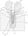
도 1은 본 발명의 실시예에 따른 치과용 임플란트가 설치된 상태를 나타내는 단면도이다.
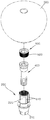
도 2는 본 발명의 실시예에 따른 치과용 임플란트의 분해 사시도이다.
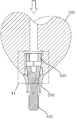
도 3은 본 발명의 실시예에 따른 치과용 임플란트의 분해 단면도이다.
도 4는 도 3에서 어버트먼트에 고정 스크루가 삽입된 상태를 나타내는 도면이다.
도 5는 본 발명의 실시예에 따른 치과용 임플란트의 일부 구성이 결합된 상태를 나타내는 단면도이다.
도 6은 도 5의 확대도이다.
도 7은 본 발명의 실시예에 따른 치과용 임플란트에서 인공치아의 회전 방지를 위한 구성을 보여주는 횡단면도이다.
도 8은 도 7의 다른 예를 나타내는 횡단면도이다.1 is a cross-sectional view showing a state in which a dental implant is installed according to an embodiment of the present invention.
2 is an exploded perspective view of a dental implant according to an embodiment of the present invention.
3 is an exploded cross-sectional view of a dental implant according to an embodiment of the present invention.
4 is a view showing a state that a fixing screw is inserted into the abutment in FIG.
5 is a cross-sectional view showing a state in which some components of the dental implant according to the embodiment of the present invention are coupled.
6 is an enlarged view of FIG. 5.
Figure 7 is a cross-sectional view showing a configuration for preventing rotation of the artificial tooth in the dental implant according to an embodiment of the present invention.
8 is a cross-sectional view illustrating another example of FIG. 7.
이하, 첨부된 도면을 참조하여 본 발명의 실시예를 더욱 상세히 설명하기로 한다. 그러나 본 발명은 이하에서 개시되는 실시예에 한정되는 것이 아니라 서로 다른 다양한 형태로 구현될 것이며, 단지 본 실시예들은 본 발명의 개시가 완전하도록 하며, 통상의 지식을 가진 자에게 발명의 범주를 완전하게 알려주기 위해 제공되는 것이다. 도면상에서 동일 부호는 동일한 요소를 지칭한다.Hereinafter, with reference to the accompanying drawings will be described an embodiment of the present invention in more detail. However, the present invention is not limited to the embodiments disclosed below, but will be implemented in various forms, and only the embodiments are intended to complete the disclosure of the present invention, and to those skilled in the art to fully understand the scope of the invention. It is provided to inform you. Like numbers refer to like elements in the figures.
본 발명의 바람직한 실시예에 따른 치과용 임플란트는, 인공치아와 어버트먼트를 상호 결합할 때 나사식 또는 접착제를 이용한 접착식 결합을 이용하지 않고 어버트먼트에 대해 인공치아를 강제 압입하여 견고히 고정할 수 있는 결합 방식을 채용함으로써 시술 시간을 단축하여 시술 경제성을 향상시킬 수 있을 뿐만 아니라 구성 부품을 감소하여 경제성을 증대시킬 수 있다.Dental implants according to a preferred embodiment of the present invention, when the artificial teeth and the abutment are mutually coupled to force the artificial teeth against the abutment firmly fixed without using the adhesive coupling using a screw or adhesive By adopting a coupling method capable of shortening the procedure time, the economical efficiency of the procedure can be improved, and the economical efficiency can be increased by reducing the component parts.
이하, 실시예를 참조하여 본 발명을 상세히 설명한다.Hereinafter, the present invention will be described in detail with reference to Examples.
도 1 내지 도 6에 도시한 바와 같이, 본 발명의 실시예에 따른 치과용 임플란트는, 픽스쳐(100), 어버트먼트(200), 인공치아(300), 고정 스크루(400)를 포함한다.As shown in FIGS. 1 to 6, the dental implant according to the embodiment of the present invention includes a
먼저, 픽스쳐(100)는 잇몸 뼈(치조골)에 나선 결합 방식을 통해 식립되어 어버트먼트(200)와 인공치아(300)를 전체적으로 지지하는 구조체 역할을 하게 된다. 픽스쳐(100)의 내부에는 체결홈(110)이 마련된다. 체결홈(110)은, 상대적으로 하측 영역에 마련되어 고정 스크루(400)와 나사 결합 가능하도록 나사산이 마련되는 제1 체결홈(111)과, 제1 체결홈(111)의 상측 영역에 마련되어 픽스쳐(100) 내측으로 어버트먼트(200)의 단부가 삽입되었을 때 어버트먼트(200)의 회전을 방지하도록 예를 들면 사각, 오각, 육각, 팔각 등의 다각형 단면 형상으로 이루어지는 제2 체결홈(112)을 포함한다.First, the
다음, 어버트먼트(200)는 픽스쳐(100)에 결합되어 인공치아(300)를 견고하게 지지하는 부분으로서, 픽스쳐(100)의 체결홈(110) 내측에 삽입되는 삽입부(210)와 픽스쳐(100) 상부로 돌출되는 돌출부(220)를 포함한다. 또한 삽입부(210)와 돌출부(220)를 관통하도록 길이 방향을 따라 관통홀(230)이 마련되며, 고정 스크루(400)는 관통홀(230)에 삽입되어 픽스쳐(100)에 나사 결합을 통해 고정됨으로써 픽스쳐(100)에 대해 어버트먼트(200)를 견고하게 고정하게 된다.Next, the
한편, 본 발명의 실시예에서는, 고정 스크루(400)를 관통홀(230)에 삽입하여 어버트먼트(200)를 픽스쳐(100)에 결합했을때 돌출부(220)의 외면이 초기 상태(고정 스크루 결합 전)에 비해 상대적으로 외측으로 더욱 확장된 상태, 즉 한층 벌어지는 상태가 되도록 한다. 후술하겠지만 본 발명은 어버트먼트(200)와 인공치아(300)가 별도의 시멘트 접착제를 이용하여 상호 결합되는 것이 아니라 강제 압입 방식을 통해 결합되며, 전술한 바와 같이 돌출부(220)의 외면이 확장되어 벌어진 상태에서 돌출부(220)에 인공치아(300)를 강제 압입하여 상호 결합 완료하게 된다.Meanwhile, in the embodiment of the present invention, when the
도 1 내지 도 4에 도시한 바와 같이, 돌출부(220)에는 그 원주 방향을 따라 서로 이격되게 복수의 절개홀(250)이 마련되어 있으며, 이러한 절개홀(250)을 통해 돌출부(220)의 외면 확장이 더욱 용이하게 실시 가능하게 된다.1 to 4, the
한편, 픽스쳐(100) 내측으로 삽입되는 어버트먼트(200)의 하부는 회전 방지를 위해 사각, 육각, 팔각 등의 다각형 형상으로 갖는 것이 바람직하고, 외측으로 돌출되는 돌출부(220)는 전체적으로 내부가 빈 원형 형상으로 이루어질 수 있다.On the other hand, the lower portion of the
다음, 인공치아(300)는 어버트먼트(200)의 돌출부(220) 외측을 감싸는 방식으로 돌출부(220)에 결합되며 구체적으로 강제 압입 방식을 통해 결합 가능하며, 이에 대한 구체적인 설명은 후술한다.Next, the
다음, 고정 스크루(400)는 관통홀(230)에 삽입되어 일단부가 픽스쳐(100)에 나사 결합을 통해 결합됨으로써 픽스쳐(100)에 대해 어버트먼트(200)를 견고하게 고정한다. 고정 스크루(400)를 어버트먼트(200)의 관통홀(230)에 완전히 삽입하고 픽스쳐(100)와 나사 결합을 완료했을 때 고정 스크루(400)에 의해 어버트먼트(200)의 돌출부(220)가 외측으로 벌어지면서 확장되며 이에 대한 구체적인 설명은 후술한다.Next, the fixing
본 발명은, 고정 스크루(400)가 어버트먼트(200)를 관통하여 픽스쳐(100)에 결합 완료됐을 때 어버트먼트(200)의 돌출부(220)가 외측으로 일정 이상 확장되며, 인공치아(300)는 확장된 돌출부(220)에 강제 압입되어 고정되는 방식을 채용하고 있으며, 이와 같이 강제 압입에 의한 고정 방식을 통해 기존의 나사식 또는 접착제를 이용한 접착식 결합을 이용하지 않게 되므로 시술 시간을 단축하여 시술 경제성을 향상시킬 수 있을 뿐만 아니라 구성 부품을 감소하여 경제성을 증대시킬 수 있다.According to the present invention, when the fixing
이하, 어버트먼트(200)의 돌출부(220) 확장과 확장된 돌출부(220)로의 인공치아(300) 강제 압입 결합에 대해 구체적으로 설명한다.Hereinafter, the extension of the
도 1 내지 도 4에 도시한 바와 같이, 어버트먼트(200)의 관통홀(230)은, 삽입부(210)와 대응하는 내면 위치에 마련되는 제1 관통홀(231)과 돌출부(220)에 대응하는 내면 위치에 마련되는 제2 관통홀(232)을 포함한다. 1 to 4, the through
여기서, 제1 관통홀(231)의 내주면에는 나사산이 마련되며, 고정 스크루(400)의 체결시 고정 스크루의 나사산과 일시적으로 상호 나사 결합 가능하다.Here, a screw thread is provided on the inner circumferential surface of the first through
본 발명에서, 제1 관통홀(231)은 어버트먼트(200)의 길이 방향을 따라 직선 형태로 마련되며, 제2 관통홀(232)은 마찬가지로 길이 방향을 따라 직선 형태로 마련되다가 특정 구간에서 경사면이 마련된다.In the present invention, the first through
부연해서, 도 2 내지 도 4에 도시한 바와 같이, 제2 관통홀(232)의 내면은 어버트먼트(200)와 고정 스크루(400)의 결합 완료시 고정 스크루(400)의 헤드부 외면과 접촉되는 영역에 마련되는 경사면을 포함한다.2 to 4, the inner surface of the second through
도 3 및 도 4에 도시한 바와 같이, 제2 관통홀(232)의 내면에는 그 둘레 방향을 따라 연속적으로 제1 경사면(260)이 마련되고, 고정 스크루(400)의 헤드부 외면에는 제1 경사면(260)과 면접촉 가능하도록 그 둘레 방향을 따라 연속적으로 제2 경사면(410)이 마련된다.As shown in FIGS. 3 and 4, the first
여기서, 제2 경사면(410)의 경사각(A2)은 제1 경사면(260)의 경사각(A1)보다 일정 이상 크게 형성된다. Here, the inclination angle A2 of the second
자세하게, 고정 스크루(400)의 길이 방향 중심축에 대해 헤드부 외면의 제2 경사면(410)의 경사각(A2)은 대략 14~16도로 형성된다. 또한, 어버트먼트(200)의 길이 방향 중심축에 대해 제1 경사면(260)의 경사각(A1)은 대략 12~13도로 형성된다.In detail, the inclination angle A2 of the second
이와 같이, 제2 경사면(410)의 경사각(A2)은 제1 경사면(260)의 경사각(A1)보다 일정 이상 크게 형성됨으로써 어버트먼트(200)의 관통홀(230)에 고정 스크루(400)를 완전히 삽입하여 픽스쳐(100)에 결합하게 되면 돌출부(220)의 외면은 일정 이상 벌어지면서 확장될 수 있으며 전술한 절개홀(250)로 인해 이러한 단면 확장은 더욱 용이하게 실시 가능하다.As such, the inclination angle A2 of the second
도 3 내지 도 6에 도시한 바와 같이, 인공치아(300)에는 어버트먼트(200)의 돌출부(220)가 삽입 가능하도록 삽입홀(310)이 마련되고, 삽입홀(310)의 내면에는 그 둘레방향을 따라 연속적으로 제3 경사면(320)이 마련된다. 삽입홀(310)의 단면 형상은 어버트먼트(200)의 돌출부(220)의 단면 형상과 대응하는 형상으로 이루어진다. 도면에서 삽입홀(310)과 연통하여 외부로 개방되는 홀은 드라이버 홀을 의미하며 드라이버 홀 내부는 별도의 충전재로 충진된다.As shown in FIGS. 3 to 6, the
본 발명의 실시예에서, 상호 결합되는 방향을 기준으로 봤을때, 제3 경사면(320)은 돌출부(220)를 향해 하향 경사지게 마련되는데 어버트먼트(200)에 대한 인공치아(300)의 삽입 방향 중심축을 기준으로 제3 경사면(320)은 돌출부(220), 즉 삽입홀(310)의 입구를 향해 하향 경사지게 마련된다.In an embodiment of the present invention, the third
본 발명에서 제3 경사면(320)의 경사각(A3)은, 고정 스크루(400)의 결합에 의해 돌출부(220)가 외측으로 확장된 상태에서의 돌출부(220)의 외면 경사각(A4)과 동일하거나 그 미만으로 형성된다.In the present invention, the inclination angle A3 of the third
여기서, 도 2 내지 도 4에 도시한 바와 같이, 확장된 상태의 돌출부(220)의 외면 경사각(A4)은 제1 경사면(260)의 경사각(A1), 제2 경사면(410)의 경사각(A2)과 상이하고 이들과는 특별한 수치적 관계를 갖지 않지만 인공치아(300)의 제3 경사면(320)의 경사각(A3)과는 전술한 바와 같이 수치적 관계를 갖는다.2 to 4, the inclination angle A4 of the outer surface of the
본 발명에서, 제3 경사면(320)의 경사각(A3)이 확장된 상태의 돌출부(220)의 외면 경사각(A4) 이하로 마련됨으로써, 시술자가 어버트먼트(200)의 상측에서 하측을 향해 인공치아(300)를 삽입할 때 단순히 인공치아(300)를 하측으로 가압하는 동작만으로도 어버트먼트(200)에 견고하게 결합할 수 있게 된다.In the present invention, the inclination angle (A3) of the third
구체적으로, 확장된 상태의 돌출부(220)의 외경은 삽입홀(310)의 입구 내경보다 일정 이상 큰 값을 갖게 되므로, 시술자에 의한 인공치아(300)의 삽입 초기시에 절개홀(250)을 통해 분리된 복수의 돌출부 편들은 내측으로 일정 이상 축소되는(오므라드는) 현상이 발생한다. 이어서 시술자가 인공치아(300)를 더욱 상측에서 가압하게 되면 돌출부(220)는 삽입홀(310) 내측으로 더 삽입될 수 있고 완전히 삽입된 상태에서는 돌출부(220)의 외면과 제3 경사면(320)은 서로 밀착하는 상태가 된다. Specifically, since the outer diameter of the
한가지 덧붙이자면, 인공치아(300)의 삽입 동작시, 돌출부(220)는 그 외면이 확장된 상태를 유지하도록 하는 탄성을 갖고 있고 돌출부(220)의 외면과 접촉되는 제3 경사면(320)은 고정 상태이므로, 시술자가 인공치아(300)를 초기에 일정 깊이로 삽입하게 되면 돌출부(220)의 탄성 복원력에 의해 인공치아(300)는 어버트먼트(200) 측으로 더욱 신속하게 이동하면서 결합될 수 있다.In addition, during the insertion operation of the
한편, 도 2 내지 도 4에 도시한 바와 같이, 삽입홀(310)의 입구 직경과 확장된 상태의 돌출부(220)의 외경 차이로 인해 인공치아(300)의 초기 삽입이 원활하지 않는 것을 보완하여 시술자가 좀 더 쉽게 인공치아(300)를 어버트먼트(200)로 초기 삽입할 수 있도록, 돌출부(220)가 삽입되는 삽입홀(310)의 입구에는 둘레 방향을 따라 테이퍼진 테이퍼면(340)이 마련된다. 마찬가지로, 인공치아(300) 내부로 삽입되는 돌출부(220)의 단부에도 경사진 테이퍼면이 마련되는 것이 바람직하다.On the other hand, as shown in Figures 2 to 4, due to the difference in the outer diameter of the inlet diameter of the
도 1 내지 도 6에 도시한 바와 같이, 본 발명은, 고정 스크루(400)의 결합에 의해 확장된 돌출부(220) 내측에 결합되는 보조 확장 스크루(500)를 더 포함한다.As shown in Figures 1 to 6, the present invention further includes an
전술한 바와 같이, 돌출부(220)는 복수의 돌출부 편으로 이루어지며 그 내측에 고정 스크루(400)가 관통 삽입되면 복수의 돌출부 편은 외측으로 확장되는 상태를 갖는다. 본 발명은, 이러한 돌출부 편들의 외측 확장을 더욱 안정적으로 유지시켜 확장된 돌출부(220)의 외면이 인공치아(300)의 삽입홀(310) 내면에 더욱 밀착되는 상태를 갖도록 보조 확장 스크루(500)가 추가된다. 이와 같이 돌출부(220)의 외면과 삽입홀(310) 내면간의 밀착 상태를 향상시킴으로써 어버트먼트(200)에 대한 인공치아(300)의 결합력을 증대시킬 수 있다.As described above, the
구체적으로, 돌출부(220)의 내주면에는 제1 나사산(510)이 마련되고 보조 확장 스크루(500)의 외면에는 제1 나사산(510)에 나사 결합 가능하도록 제2 나사산(520)이 마련된다. 즉, 복수의 돌출부 편을 포함하는 돌출부(220)와 보조 확장 스크루(500)는 서로 간에 나사 결합 방식을 통해 결합되며, 보조 확장 스크루(500)는 예를 들어 서로 이격된 4개의 돌출부 편을 일체로 연결하여 4개의 돌출부 편이 거의 동일한 형상을 갖도록 할 수 있고 견고한 결합력을 유지할 수 있다. 즉, 4개의 돌출부 편이 대략 서로 간에 동일한 상태(각도, 길이 등)로 확장된 상태를 유지하도록 할 수 있으며, 이에 따라 인공치아(300)의 삽입홀(310) 내면의 원주 방향을 따라 실질적으로 균일한 접촉을 유지하게 할 수 있다.In detail, a
또한, 도 2 내지 도 4에 도시한 바와 같이, 본 발명에서, 보조 확장 스크루(500)의 단면적은 일단(인공치아에 상대적으로 근접)에서 타단(인공치아로부터 상대적으로 이격)으로 갈수록 점차 감소하도록 마련된다. 이에 따라 고정 스크루(400)의 결합을 통해 일차적으로 확장된 돌출부(220)를 보조 확장 스크루(500)의 결합을 통해 추가적으로 확장시켜(벌려서) 돌출부(220)의 외면과 인공치아(300)의 삽입홀(310) 내면간의 밀착 상태를 더욱 안정적으로 유지시킬 수 있다.2 to 4, in the present invention, the cross-sectional area of the
도 7 및 도 8에 도시한 바와 같이, 본 발명에서, 돌출부(220)와 인공치아(300)에는, 돌출부(220)에 인공치아(300)가 결합된 상태에서 인공치아(300)의 회전을 방지하기 위한 회전방지부(600)가 더 마련된다.As shown in FIG. 7 and FIG. 8, in the present invention, the
구체적으로, 도 7에 도시한 바와 같이, 회전방지부(600)는, 돌출부(220)의 외면에 적어도 하나로 마련되는 제1 회전방지면(610)과 인공치아(300)의 삽입홀(310) 내면에 제1 회전방지면(610)과 면접촉 가능하도록 적어도 하나로 마련되는 제2 회전방지면(620)을 포함한다. 관련 도면에는 제1 회전방지면(610)과 제2 회전방지면(620)이 각각 1개씩 마련된 경우가 도시되어 있지만 반드시 이에 한정되지 않으며 둘 이상의 개수로 마련될 수도 있다. 돌출부(220)에 인공치아(300)를 삽입 완료한 상태에서, 돌출부(220)의 외면은 인공치아(300)의 삽입홀(310) 내면에 밀착하게 되는데 이때 제1 회전방지면(610) 또한 제2 회전방지면(620)에 밀착함으로써 인공치아(300)의 회전이 방지된다. Specifically, as shown in Figure 7, the
다른 예로, 도 8에 도시한 바와 같이, 돌출부(220)의 복수의 돌출부 편 외면에 각각 복수의 돌기(700)를 마련하고, 제3 경사면(320)에 그 길이 방향(어버트먼트에 대한 인공치아의 삽입 방향)을 따라 길게 상기 복수의 돌기(700)에 대응하여 복수의 돌기가 각각 삽입되도록 돌기 삽입홈(710)을 마련할 수 있다. 이러한 경우, 인공치아(300)와 어버트먼트(200)가 상호 결합된 상태에서 인공치아(300)의 회전 발생을 더욱 방지할 수 있다. 부연하자면, 돌기(700)는 기어 이빨처럼 돌출부(220)의 외면 원주방향을 따라 동일한 간격으로 반복 형성될 수 있고 마찬가지로 돌기 삽입홈(710) 또한 대응하게 형성되며, 일 예로 돌기(700)의 개수가 72개인 경우 시술자는 어버트먼트(200)에 대해 5도의 간격으로 인공치아(300)의 결합 방향을 조절할 수도 있다.As another example, as shown in FIG. 8, a plurality of
관련 도면에는 돌기(700)가 돌출부(220)의 외면 둘레 방향을 따라 전체적으로 연속적으로 마련되지 않고 부분적으로 마련된 경우가 도시되어 있으며, 이런 구조를 적용할 경우에도 마찬가지로 결합 방향 조절이 가능하게 되며, 전체 영역에 걸쳐 형성할 경우에 비해 가공 비용을 절감할 수 있다.In the related drawings, a case in which the
결합 순서에 대해 간략하게 설명하면, 먼저 픽스쳐(100)를 치조골에 고정하고 이어 픽스쳐(100)에 어버트먼트(200)를 삽입한다. 이어서 고정 스크루(400)를 어버트먼트(200) 내측에 삽입하여 결합하되 완전히 결합시키지 않고 돌출부(220)가 일정 부분 벌어질 정도로 결합한다. 이후 돌출부(220) 상측에 보조 확장 스크루(500)를 결합하고 돌출부(220)의 상측에 인공치아(300)를 강제 압입하여 고정한다. 이어서, 인공치아(300)의 삽입홀(310)과 연통되는 공구 삽입홀을 통해 렌치 등과 같은 체결도구를 삽입하여 고정 스크루(400)를 어버트먼트(200)에 더욱 결합하여 돌출부(220)가 더욱 확장되도록 한다. 이어서 인공치아(300)의 개구된 홀을 충진재 등으로 채워서 마무리한다.Briefly describing the coupling sequence, the
본 발명은, 첫째 돌출부(220)는 일정 이상의 탄성을 갖는 재질로 이루어짐과 더불어 그 둘레 방향으로 이격 형성된 복수의 절개홀(250)로 인해 외력에 대해 일정 이상의 탄성을 갖게 되고, 둘째 제3 경사면(320)의 경사각(A3)이 고정 스크루(400)의 결합에 의해 돌출부(220)가 외측으로 확장된 상태에서의 돌출부(220)의 외면 경사각(A4) 이하로 형성되고, 셋째 보조 확장 스크루(500)에 의한 돌출부(220)의 확장 상태 유지, 추가 확장과 같은 이유 등으로 인해, 인공치아(300)의 강제 압입 결합이 가능하게 되고 압입 완료시에는 제3 경사면(320)과 돌출부(220) 외면이 서로 밀착하여 견고한 결합 상태를 유지할 수 있다.According to the present invention, the
본 발명을 첨부 도면과 전술된 바람직한 실시예를 참조하여 설명하였으나, 본 발명은 그에 한정되지 않으며, 후술되는 특허청구범위에 의해 한정된다. 따라서, 본 기술분야의 통상의 지식을 가진 자라면 후술되는 특허청구범위의 기술적 사상에서 벗어나지 않는 범위 내에서 본 발명을 다양하게 변형 및 수정할 수 있다.Although the invention has been described with reference to the accompanying drawings and the preferred embodiments described above, the invention is not limited thereto, but is defined by the claims that follow. Accordingly, one of ordinary skill in the art may variously modify and modify the present invention without departing from the spirit of the following claims.
100: 픽스쳐
200: 어버트먼트
210: 삽입부
220: 돌출부
250: 절개홀
260: 제1 경사면
320: 제3 경사면
340: 테이퍼면
400: 고정 스크루
410: 제2 경사면
500: 보조 확장 스크루
600: 회전 방지부
610: 제1 회전방지면
620: 제2 회전방지면
A1, A2, A3: 경사각
A4: 외면 경사각100: fixture 200: abutment
210: insertion portion 220: protrusion
250: incision hole 260: first inclined surface
320: third inclined surface 340: tapered surface
400: fixed screw 410: second inclined surface
500: auxiliary expansion screw 600: anti-rotation unit
610: first anti-rotation surface 620: second anti-rotation surface
A1, A2, A3: Tilt Angle A4: External Tilt Angle
Claims (10)
상기 픽스쳐(100)의 체결홈(110)에 삽입되는 삽입부(210), 상기 픽스쳐(100) 상부로 돌출되는 돌출부(220) 및 상기 삽입부(210)와 돌출부(220)를 관통하는 관통홀(230)을 포함하며, 상기 돌출부(220)는 외력에 의해 일정 이상 외측으로 확장 가능하도록 그 원주 방향을 따라 서로 이격되게 복수의 절개홀(250)이 마련되는 어버트먼트(200);
상기 어버트먼트(200)의 돌출부 외측을 감싸는 방식으로 상기 돌출부(220)에 결합되는 인공치아(300); 및
상기 관통홀(230)에 삽입되어 일단부가 상기 픽스쳐(100)에 결합됨으로써 상기 픽스쳐(100)에 대해 상기 어버트먼트(200)를 고정하는 고정 스크루(400)를 포함하며,
상기 고정 스크루(400)의 결합시 상기 어버트먼트(200)의 돌출부가 외측으로 일정 이상 확장되며, 상기 인공치아(300)는 확장된 돌출부(220)에 강제 압입되어 결합 가능한 치과용 임플란트.A fixture 100 placed in the gum bone;
Insertion portion 210 to be inserted into the fastening groove 110 of the fixture 100, a protrusion 220 protruding into the fixture 100, and a through hole penetrating the insertion portion 210 and the protrusion 220 An abutment (200) comprising: abutments (200) provided with a plurality of incision holes (250) spaced apart from each other in the circumferential direction thereof so as to extend outward by a predetermined or more by an external force;
An artificial tooth 300 coupled to the protrusion 220 in such a manner as to surround the outside of the protrusion of the abutment 200; And
It is inserted into the through hole 230, one end is coupled to the fixture 100 includes a fixing screw 400 for fixing the abutment 200 with respect to the fixture 100,
When the fixing screw 400 is coupled to the protrusion of the abutment 200 is extended to a predetermined or more outward, the artificial tooth (300) is a dental implant that can be combined by forcibly pressed into the extended protrusion (220).
상기 관통홀(230)은, 상기 삽입부(210)와 대응하는 위치에 마련되는 제1 관통홀(231)과 상기 돌출부(220)에 대응하는 위치에 마련되는 제2 관통홀(232)을 포함하고,
상기 제2 관통홀(232)의 내면에는 그 둘레 방향을 따라 연속적으로 제1 경사면(260)이 마련되고, 상기 고정 스크루(400)의 헤드부 외면에는 상기 제1 경사면(260)과 면접촉 가능하도록 그 둘레 방향을 따라 연속적으로 제2 경사면(410)이 마련되되,
상기 제2 경사면(410)의 경사각(A2)은 상기 제1 경사면(260)의 경사각(A1)보다 큰 것을 특징으로 하는 치과용 임플란트.The method of claim 1,
The through hole 230 includes a first through hole 231 provided at a position corresponding to the insertion portion 210 and a second through hole 232 provided at a position corresponding to the protrusion 220. and,
The first inclined surface 260 is continuously provided in the inner surface of the second through hole 232 along the circumferential direction thereof, and the outer surface of the head of the fixing screw 400 may be in surface contact with the first inclined surface 260. The second inclined surface 410 is continuously provided along its circumferential direction,
Dental implant, characterized in that the inclination angle (A2) of the second inclined surface (410) is greater than the inclination angle (A1) of the first inclined surface (260).
상기 인공치아(300)에는 상기 어버트먼트(200)의 돌출부(220)가 삽입 가능하도록 삽입홀(310)이 마련되고, 상기 삽입홀(310)의 내면에는 그 둘레방향을 따라 연속적으로 제3 경사면(320)이 마련되되, 상기 제3 경사면(320)은 상기 돌출부(220)를 향해 하향 경사지게 마련되는 것을 특징으로 하는 치과용 임플란트.The method of claim 2,
The artificial tooth 300 is provided with an insertion hole 310 to insert the protrusion 220 of the abutment 200, the inner surface of the insertion hole 310 continuously in the circumferential direction of the third An inclined surface 320 is provided, wherein the third inclined surface 320 is inclined downward toward the protrusion 220.
상기 제3 경사면(320)의 경사각(A3)은, 상기 고정 스크루(400)의 결합에 의해 상기 돌출부(220)가 외측으로 확장된 상태에서의 상기 돌출부(220)의 외면 경사각(A4)과 동일하거나 그 미만인 것을 특징으로 하는 치과용 임플란트.The method of claim 3,
The inclination angle A3 of the third inclined surface 320 is the same as the inclination angle A4 of the outer surface of the protrusion 220 in a state in which the protrusion 220 is extended outward by engagement of the fixing screw 400. Dental implants, characterized in that less than or less.
상기 돌출부(220)가 삽입되는 상기 삽입홀(310)의 입구에는 둘레 방향을 따라 테이퍼진 테이퍼면(340)이 마련되는 것을 특징으로 하는 치과용 임플란트.The method of claim 3,
Dental implant, characterized in that the tapered surface 340 is provided at the inlet of the insertion hole 310 is inserted into the protrusion 220 along the circumferential direction.
상기 돌출부(220)와 상기 인공치아(300)에는 상기 돌출부(220)에 인공치아(300)가 결합된 상태에서 인공치아(300)의 회전을 방지하기 위한 회전방지부(600)가 더 마련되는 것을 특징으로 하는 치과용 임플란트.The method of claim 3,
The protrusion 220 and the artificial tooth 300 is further provided with an anti-rotation part 600 for preventing rotation of the artificial tooth 300 in a state where the artificial tooth 300 is coupled to the protrusion 220. Dental implant, characterized in that.
상기 회전방지부(600)는,
상기 돌출부(220)의 외면에 적어도 하나로 마련되는 제1 회전방지면(610); 및
상기 인공치아(300)의 삽입홀(310) 내면에 상기 제1 회전방지면(610)과 면접촉 가능하도록 적어도 하나로 마련되는 제2 회전방지면(620)을 포함하는 것을 특징으로 하는 치과용 임플란트.The method of claim 6,
The anti-rotation unit 600,
A first anti-rotation surface 610 provided on at least one outer surface of the protrusion 220; And
Dental implants, characterized in that it comprises a second anti-rotation surface 620 is provided on the inner surface of the insertion hole 310 of the artificial tooth 300 at least one to be in surface contact with the first anti-rotation surface 610. .
상기 고정 스크루(400)의 결합에 의해 확장된 돌출부(220) 내측에 결합되어 확장된 돌출부(220)를 상기 인공치아(300)의 삽입홀(310) 내면에 밀착시키는 보조 확장 스크루(500)를 더 포함하는 것을 특징으로 하는 치과용 임플란트.The method of claim 1,
The auxiliary extension screw 500 coupled to the inside of the extended protrusion 220 by the coupling of the fixing screw 400 to closely contact the inner surface of the insertion hole 310 of the artificial tooth 300. Dental implants further comprising.
상기 돌출부(220)의 내주면에는 나사산이 마련되고 상기 보조 확장 스크루(500)의 외면에는 상기 나사산에 나사 결합 가능하도록 다른 나사산이 마련되는 것을 특징으로 하는 치과용 임플란트.The method of claim 8,
A dental implant is provided on the inner circumferential surface of the protrusion 220 and another thread is provided on the outer surface of the auxiliary extension screw 500 to be screwable to the thread.
상기 보조 확장 스크루(500)의 단면적은 일단에서 타단으로 갈수록 점차 감소하도록 마련되는 것을 특징으로 하는 치과용 임플란트.
The method of claim 8,
Dental implant, characterized in that the cross-sectional area of the auxiliary expansion screw 500 is provided to gradually decrease from one end to the other end.
Priority Applications (1)
| Application Number | Priority Date | Filing Date | Title |
|---|---|---|---|
| KR1020180062263A KR102131972B1 (en) | 2018-05-31 | 2018-05-31 | Dental implant |
Applications Claiming Priority (1)
| Application Number | Priority Date | Filing Date | Title |
|---|---|---|---|
| KR1020180062263A KR102131972B1 (en) | 2018-05-31 | 2018-05-31 | Dental implant |
Publications (2)
| Publication Number | Publication Date |
|---|---|
| KR20190136480A true KR20190136480A (en) | 2019-12-10 |
| KR102131972B1 KR102131972B1 (en) | 2020-07-09 |
Family
ID=69002815
Family Applications (1)
| Application Number | Title | Priority Date | Filing Date |
|---|---|---|---|
| KR1020180062263A KR102131972B1 (en) | 2018-05-31 | 2018-05-31 | Dental implant |
Country Status (1)
| Country | Link |
|---|---|
| KR (1) | KR102131972B1 (en) |
Cited By (9)
| Publication number | Priority date | Publication date | Assignee | Title |
|---|---|---|---|---|
| KR102104765B1 (en) * | 2020-01-28 | 2020-05-29 | 고병욱 | Durable dental implant |
| KR102198234B1 (en) * | 2019-12-27 | 2021-01-05 | (주) 코웰메디 | Cenemtless dental implant |
| KR102198233B1 (en) * | 2019-12-16 | 2021-01-05 | (주) 코웰메디 | Cenemt-free dental implant |
| KR102198237B1 (en) * | 2020-01-14 | 2021-01-05 | (주) 코웰메디 | Cenemtless dental implant using elastic bushing |
| KR102343203B1 (en) * | 2021-04-22 | 2021-12-23 | 맹선호 | Implant for artificial teeth |
| KR102352797B1 (en) * | 2021-04-27 | 2022-01-17 | 김재경 | Implant for artificial teeth |
| KR102443916B1 (en) * | 2021-11-09 | 2022-09-16 | 주식회사 피엔유에드 | An integral implant structure with a link structure |
| KR20220140285A (en) * | 2021-04-09 | 2022-10-18 | 오스템임플란트 주식회사 | Abutment assembly |
| KR20230083490A (en) * | 2021-12-03 | 2023-06-12 | 주식회사 디오 | dental restoration set |
Families Citing this family (2)
| Publication number | Priority date | Publication date | Assignee | Title |
|---|---|---|---|---|
| KR102214900B1 (en) * | 2020-12-09 | 2021-02-10 | 이경택 | dental implant system with crown with good load-absorbing internal surface |
| KR102427069B1 (en) * | 2021-08-04 | 2022-07-29 | 덴탈오케이 주식회사 | Implant crown fastening structure and fastening method |
Citations (7)
| Publication number | Priority date | Publication date | Assignee | Title |
|---|---|---|---|---|
| KR20000056128A (en) * | 1999-02-12 | 2000-09-15 | 정필훈 | Controlled morphological osteocompressive implant for immediate loading |
| KR20030061625A (en) * | 2002-01-15 | 2003-07-22 | 장상건 | Implant System |
| KR20080112896A (en) * | 2007-10-24 | 2008-12-26 | 김재성 | Anti-screwloosening device for implant |
| KR101029068B1 (en) * | 2010-06-10 | 2011-04-15 | (주) 시원 | Frictional abutment |
| KR20160029875A (en) * | 2014-09-05 | 2016-03-16 | 장은수 | Dental implant apparatus and dental member for preventing loose |
| KR101608176B1 (en) * | 2015-06-08 | 2016-03-31 | 김광섭 | Implant unit |
| KR101768410B1 (en) | 2017-01-18 | 2017-08-17 | 박건제 | Locking link and assembling method thereof |
-
2018
- 2018-05-31 KR KR1020180062263A patent/KR102131972B1/en active IP Right Grant
Patent Citations (7)
| Publication number | Priority date | Publication date | Assignee | Title |
|---|---|---|---|---|
| KR20000056128A (en) * | 1999-02-12 | 2000-09-15 | 정필훈 | Controlled morphological osteocompressive implant for immediate loading |
| KR20030061625A (en) * | 2002-01-15 | 2003-07-22 | 장상건 | Implant System |
| KR20080112896A (en) * | 2007-10-24 | 2008-12-26 | 김재성 | Anti-screwloosening device for implant |
| KR101029068B1 (en) * | 2010-06-10 | 2011-04-15 | (주) 시원 | Frictional abutment |
| KR20160029875A (en) * | 2014-09-05 | 2016-03-16 | 장은수 | Dental implant apparatus and dental member for preventing loose |
| KR101608176B1 (en) * | 2015-06-08 | 2016-03-31 | 김광섭 | Implant unit |
| KR101768410B1 (en) | 2017-01-18 | 2017-08-17 | 박건제 | Locking link and assembling method thereof |
Cited By (10)
| Publication number | Priority date | Publication date | Assignee | Title |
|---|---|---|---|---|
| KR102198233B1 (en) * | 2019-12-16 | 2021-01-05 | (주) 코웰메디 | Cenemt-free dental implant |
| WO2021125544A1 (en) * | 2019-12-16 | 2021-06-24 | (주) 코웰메디 | Cementless type dental implant |
| KR102198234B1 (en) * | 2019-12-27 | 2021-01-05 | (주) 코웰메디 | Cenemtless dental implant |
| KR102198237B1 (en) * | 2020-01-14 | 2021-01-05 | (주) 코웰메디 | Cenemtless dental implant using elastic bushing |
| KR102104765B1 (en) * | 2020-01-28 | 2020-05-29 | 고병욱 | Durable dental implant |
| KR20220140285A (en) * | 2021-04-09 | 2022-10-18 | 오스템임플란트 주식회사 | Abutment assembly |
| KR102343203B1 (en) * | 2021-04-22 | 2021-12-23 | 맹선호 | Implant for artificial teeth |
| KR102352797B1 (en) * | 2021-04-27 | 2022-01-17 | 김재경 | Implant for artificial teeth |
| KR102443916B1 (en) * | 2021-11-09 | 2022-09-16 | 주식회사 피엔유에드 | An integral implant structure with a link structure |
| KR20230083490A (en) * | 2021-12-03 | 2023-06-12 | 주식회사 디오 | dental restoration set |
Also Published As
| Publication number | Publication date |
|---|---|
| KR102131972B1 (en) | 2020-07-09 |
Similar Documents
| Publication | Publication Date | Title |
|---|---|---|
| KR20190136480A (en) | Dental implant | |
| EP1862142B1 (en) | Healing abutment | |
| KR101173758B1 (en) | Implant unit using hook pin combination structure | |
| EP1333771B1 (en) | Positioning device for setting implanted bearing dental prostheses | |
| KR102303869B1 (en) | Dental implant | |
| JP6410602B2 (en) | Set of dental components | |
| KR101296741B1 (en) | Healing abutment | |
| KR20050042220A (en) | Components for improved impression making | |
| KR20010030908A (en) | Single stage implant system | |
| KR102173435B1 (en) | Dental prosthesis system | |
| KR102551331B1 (en) | Abutment assembly | |
| TWI644656B (en) | Implant structure and abutment | |
| KR101727732B1 (en) | Dental implant structure | |
| KR101089069B1 (en) | A connector and implant including the same | |
| KR100779227B1 (en) | Dental implant | |
| KR102470652B1 (en) | Implant impression coping with improved connecting structure | |
| KR20120017951A (en) | Multi abutment device | |
| KR102332598B1 (en) | Implant system with good internal load absorption | |
| KR101642743B1 (en) | Hybrid type dental implant structure | |
| KR101850798B1 (en) | Scanbody for mouth structure scan | |
| KR20200014558A (en) | Abutment assembly | |
| KR20240082185A (en) | Cementless abutment assembly | |
| KR101662279B1 (en) | Anti-loosing structure for implant | |
| KR101486851B1 (en) | Dental Implant Abutment | |
| KR20100090006A (en) | Fixture of dental implant |
Legal Events
| Date | Code | Title | Description |
|---|---|---|---|
| A201 | Request for examination | ||
| E902 | Notification of reason for refusal | ||
| E701 | Decision to grant or registration of patent right |