KR20190136174A - Band type pipe leakage detecting apparatus and pipe leakage detecting method using the same - Google Patents
Band type pipe leakage detecting apparatus and pipe leakage detecting method using the same Download PDFInfo
- Publication number
- KR20190136174A KR20190136174A KR1020180061498A KR20180061498A KR20190136174A KR 20190136174 A KR20190136174 A KR 20190136174A KR 1020180061498 A KR1020180061498 A KR 1020180061498A KR 20180061498 A KR20180061498 A KR 20180061498A KR 20190136174 A KR20190136174 A KR 20190136174A
- Authority
- KR
- South Korea
- Prior art keywords
- pipe
- band
- leak detection
- detection device
- hole
- Prior art date
Links
Images


Classifications
-
- G—PHYSICS
- G01—MEASURING; TESTING
- G01M—TESTING STATIC OR DYNAMIC BALANCE OF MACHINES OR STRUCTURES; TESTING OF STRUCTURES OR APPARATUS, NOT OTHERWISE PROVIDED FOR
- G01M3/00—Investigating fluid-tightness of structures
- G01M3/02—Investigating fluid-tightness of structures by using fluid or vacuum
- G01M3/04—Investigating fluid-tightness of structures by using fluid or vacuum by detecting the presence of fluid at the leakage point
- G01M3/16—Investigating fluid-tightness of structures by using fluid or vacuum by detecting the presence of fluid at the leakage point using electric detection means
- G01M3/18—Investigating fluid-tightness of structures by using fluid or vacuum by detecting the presence of fluid at the leakage point using electric detection means for pipes, cables or tubes; for pipe joints or seals; for valves; for welds; for containers, e.g. radiators
Abstract
Description
본 발명은 배관 누설 검출 장치 및 이를 이용한 배관 누설 검출 시스템에 관한 것으로, 더욱 상세하게는 배관에 고정되어 배관의 누설 여부 및 누설 위치를 신속하게 검출할 수 있고, 이를 통해 배관에서 발생하는 사고에 대한 확산 차단 및 복구를 신속하게 수행하도록 하는 밴드형 배관 누설 검출 장치 및 이를 이용한 배관 누설 검출 시스템에 관한 것이다.The present invention relates to a pipe leak detection apparatus and a pipe leak detection system using the same, and more particularly, it is fixed to a pipe to detect whether the pipe is leaking and the leak location quickly, and through this, The present invention relates to a band-type pipe leak detection device and a pipe leak detection system using the same.
일반적으로 배관은 유체 및 가스의 운반수단으로서 거의 모든 산업시설이나 일반 생활에서 매우 중요한 역할을 담당하고 있다.In general, piping plays a very important role in almost all industrial facilities and general life as a means of transporting fluids and gases.
이러한 배관은 사용 년 수가 증가함에 따라 크랙(crack) 등과 같은 배관 내부 벽면의 손상 또는 외부 하중에 의한 손상이 발생될 수 있으며, 이러한 배관의 손상에 따른 유체 및 가스의 누설은 심각한 경제적 및 인적 손실을 유발할 수 있으므로 배관의 누설 유무를 감지할 필요가 있다.These pipes can be damaged by internal loads or external loads such as cracks, etc. as the number of years of use increases, and leakage of fluids and gases due to such pipe damages can cause serious economic and human losses. It may be necessary to detect the leakage of pipes.
종래에는 제10-2009-0003195호, 제10-1836085호 등에서와 같이 배관 내부에 유동압력센서, 유량센서 또는 배관 외부에 부착한 음향센서, 진동센서 등을 설치하여, 상기 센서들의 감지값이 미리 설정된 기준치를 넘을 경우 배관이 누설되고 있는 것으로 판단하는 방법을 이용하고 있다.Conventionally, as in Nos. 10-2009-0003195 and 10-1836085, a flow pressure sensor, a flow sensor, or an acoustic sensor attached to the outside of a pipe, a vibration sensor, or the like are installed in a pipe, so that the detection values of the sensors are previously determined. If the standard value is exceeded, the pipe is considered to be leaking.
그러나, 배관 누설 시 신속한 대응을 위해서는 누설 여부와 동시에 누설 위치를 정확하게 감지할 필요가 있으며, 이를 위해서는 다양한 위치에 많은 센서를 부착할 필요가 있다. 기존의 유동압력센서와 유량센서의 경우 배관 천공이 필요하여 배관계 내 다양한 위치에 설치하는데 어려움이 있으며, 음향센서와 진동센서는 고가의 분석 장비를 사용하여도 누설 위치의 정확한 탐지가 쉽지 않고, 외부 충격 신호에 영향을 받는 등의 단점이 있다. However, in order to respond quickly when the pipe leaks, it is necessary to accurately detect the leak position at the same time as leaking, and for this purpose, it is necessary to attach many sensors at various positions. Existing flow pressure sensor and flow sensor need to be installed in various places in the piping system because the pipe is required for drilling, and the acoustic sensor and vibration sensor are not easy to detect the leak position even if expensive analysis equipment is used. There are disadvantages such as being affected by the impact signal.
이에, 본 발명의 기술적 과제는 이러한 점에서 착안된 것으로 본 발명의 목적은 배관에 고정되어 배관의 누설 여부 및 누설 위치를 신속하게 검출할 수 있고, 이를 통해 배관 누출 사고의 확산 차단 및 복구를 신속하게 수행하도록 하는 밴드형 배관 누설 검출 장치에 관한 것이다.Therefore, the technical problem of the present invention has been conceived in this regard, the object of the present invention is to be fixed to the pipe can quickly detect whether the leakage of the pipe and the leak location, through which the rapid blocking and recovery of the leak of pipe leakage accident It relates to a band-type pipe leak detection device to be performed.
본 발명의 다른 목적은 상기 밴드형 배관 누설 검출 장치를 이용한 배관 누설 검출 시스템에 관한 것이다.Another object of the present invention relates to a pipe leak detection system using the band-type pipe leak detection device.
상기한 본 발명의 목적을 실현하기 위한 일 실시예에 따른 배관 누설 검출 장치는, 배관에 고정되어 상기 배관의 누설을 검출하는 배관 누설 검출 장치에 있어서, 각각의 일단부가 서로 연결되고, 상기 일단부를 중심으로 회전하여 서로 링(ring) 형상으로 상기 배관에 탈착 가능하도록 결합하는 제1 및 제2 밴드부들, 상기 제1 및 제2 밴드부들 각각의 일단부에 결합되어 상기 제1 및 제2 밴드부들을 연결하는 체결수단 및 상기 제1 및/또는 제2 밴드부의 내부에 위치하여 상기 배관의 누설을 감지하는 누설감지센서를 포함한다.In the pipe leak detection device according to an embodiment for realizing the object of the present invention, the pipe leak detection device is fixed to the pipe to detect the leakage of the pipe, each one end is connected to each other, First and second band parts which are rotatably coupled to each other so as to be detachably coupled to the pipe in a ring shape, and are coupled to one ends of the first and second band parts, respectively. It includes a fastening means for connecting and a leak detection sensor located inside the first and / or second band portion to detect the leakage of the pipe.
일 실시예에서, 상기 체결수단은 상기 제1 및 제2 밴드부들 각각의 일단부 사이에 연장되는 연결부재 및 상기 연결부재를 관통하여 상기 제1 및 제2 밴드부들 각각의 일단부에 형성된 체결공에 삽입되는 나사체결부재를 포함할 수 있다.In one embodiment, the fastening means is a connecting member extending between one end of each of the first and second band portions and a fastening hole formed in one end of each of the first and second band portions through the connecting member It may include a screw fastening member inserted into.
일 실시예에서, 상기 제1 및 제2 밴드부들 각각의 제1 끝단에 서로 마주보도록 위치하며 관통된 제1 및 제2 관통공들이 각각 형성되고, 상기 제1 및 제2 밴드부들 각각의 제2 끝단에 서로 마주보도록 위치하며 관통된 제3 및 제4 관통공들이 각각 형성될 수 있다.In one embodiment, the first and second through-holes are formed at the first end of each of the first and second band portions to face each other, respectively, and the second of each of the first and second band portions The third and fourth through holes which are positioned to face each other at the end and are penetrated may be formed, respectively.
일 실시예에서, 상기 제1 및 제2 관통공들을 관통하여 상기 제1 및 제2 밴드부들 각각의 제1 끝단을 서로 고정시키는 제1 고정부재 및 상기 제3 및 제4 관통공을 관통하여 상기 제1 및 제2 밴드부들 각각의 제2 끝단을 서로 고정시키는 제2 고정부재를 더 포함할 수 있다.In one embodiment, the first fixing member for fixing the first end of each of the first and second band portion by passing through the first and second through holes and the third and fourth through holes through A second fixing member for fixing the second end of each of the first and second band portion may be further included.
일 실시예에서, 상기 제1 및 제2 밴드부들은 서로 소정 간격으로 갭을 형성하며, 상기 갭은 배관의 직경에 따라 조정될 수 있다.In one embodiment, the first and second band portions form a gap at a predetermined interval from each other, the gap may be adjusted according to the diameter of the pipe.
일 실시예에서, 상기 누설감지센서는 접촉압력센서, 변형률센서, 온도센서 중 어느 하나일 수 있다.In one embodiment, the leak detection sensor may be any one of a contact pressure sensor, a strain sensor, a temperature sensor.
일 실시예에서, 상기 누설감지센서는 상기 제1 및/또는 제2 밴드부의 내주면에 형성되며 일 측면이 플레이트 형상으로 형성되는 홈부에 위치할 수 있다.In one embodiment, the leak detection sensor is formed on the inner circumferential surface of the first and / or second band portion may be located in the groove portion one side is formed in a plate shape.
일 실시예에서, 상기 홈부의 내부에는 상기 홈부의 일 측면과 접하도록 상단면이 플레이트 형상으로 형성되고 상기 배관의 외면과 접하도록 하단면이 굴곡지게 형성된 블록(block)이 위치될 수 있다.In an embodiment, a block may be formed in the groove portion, the upper surface of which is formed in a plate shape to contact one side of the groove, and the lower surface of which is curved to contact the outer surface of the pipe.
일 실시예에서, 상기 누설감지센서는 상기 홈부의 일 측면 및 상기 블록의 상단면 사이의 갭에 위치되어, 상기 홈부의 일 측면 및 상기 블록의 상단면과 접촉될 수 있다.In one embodiment, the leak detection sensor is located in the gap between one side of the groove portion and the top surface of the block, it may be in contact with one side of the groove portion and the top surface of the block.
일 실시예에서, 상기 누설감지센서는 상기 제1 및/또는 제2 밴드부의 내부에 형성되며, 일 측면 및 타측면이 플레이트 형상으로 형성되는 홀(hole)에 위치할 수 있다.In one embodiment, the leak detection sensor may be formed inside the first and / or second band portion, and may be located in a hole in which one side and the other side are formed in a plate shape.
일 실시예에서, 상기 홀의 내부에는 상기 홀의 일 측면과 접하도록 상단면이 플레이트 형상으로 형성되고 상기 홀의 타 측면과 접하도록 하단면이 플레이트 형상으로 형성된 블록이 위치될 수 있다.In one embodiment, a block having an upper surface formed in a plate shape to contact one side of the hole and a lower surface formed in a plate shape to contact the other side of the hole may be located inside the hole.
일 실시예에서, 상기 누설감지센서는 상기 홀의 일 측면 및 상기 블록의 상단면 사이의 갭에 위치되거나, 또는 상기 홀의 타 측면 및 상기 블록의 하단면 사이의 갭에 위치될 수 있다.In one embodiment, the leak detection sensor may be located in the gap between one side of the hole and the top surface of the block, or in the gap between the other side of the hole and the bottom surface of the block.
상기한 본 발명의 다른 목적을 실현하기 위한 일 실시예에 따른 상기 배관 누설 검출 장치를 이용한 배관 누설 검출 시스템은, 배관에 고정되어 상기 배관의 누설을 검출하는 배관 누설 검출 장치, 상기 배관에서 누설이 발생하는 경우 누설된 배관에 관한 정보를 수집 및 변환하는 제어부 및 상기 제어부에서 수집 및 변환한 배관에 관한 정보를 외부 장치로 전송하는 데이터 전송부를 포함하고, 상기 배관 누설 검출장치는 각각의 일단부가 서로 연결되고, 상기 일단부를 중심으로 회전하여 서로 링(ring) 형상으로 상기 배관에 탈착 가능하도록 결합하는 제1 및 제2 밴드부들, 상기 제1 및 제2 밴드부들 각각의 일단부에 결합되어 상기 제1 및 제2 밴드부들을 연결하는 체결수단 및 상기 제1 및/또는 제2 밴드부의 내부에 위치하여 상기 배관의 누설을 감지하는 누설감지센서를 포함하는 것을 특징으로 한다.According to another aspect of the present invention, a pipe leak detection system using the pipe leak detection device includes a pipe leak detection device fixed to a pipe to detect a leak of the pipe, and a leak in the pipe. And a control unit for collecting and converting information about the leaked pipe, and a data transmission unit for transmitting information about the pipe collected and converted by the control unit to an external device. The first and second band parts connected to each other so as to be detachably coupled to the pipe in a ring shape by rotating about the one end part, and coupled to one ends of each of the first and second band parts. Fastening means for connecting the first and second band portion and the inside of the first and / or second band portion to detect the leakage of the pipe It characterized in that it comprises a leak detection sensor.
본 발명의 실시예들에 의하면, 제1 및 제2 밴드부들은 링(ring) 형태로 서로 결합하거나 회전을 통해 서로 개방될 수 있어 배관의 외면에 탈부착이 가능하여, 배관에 용이하게 고정할 수 있음은 물론 유지보수가 필요한 경우 배관으로부터 용이하게 분리될 수 있다.According to the embodiments of the present invention, the first and second band parts may be coupled to each other in a ring form or may be opened to each other by rotation, so that the first and second band parts may be detachably attached to the outer surface of the pipe, thereby being easily fixed to the pipe. Of course, it can be easily separated from the pipe when maintenance is required.
또한, 제1 및/또는 제2 밴드부들의 내측면에 형성된 홈부에 누설감지센서를 위치시키는 경우, 상기 누설감지센서 중 접촉압력센서와 변형률센서는 배관 내 유동압력의 변화를 감지하고, 온도센서는 주위 온도 변화를 감지하여 누설 여부를 용이하게 파악할 수 있다. In addition, when the leak detection sensor is located in the groove formed on the inner side of the first and / or second band portion, the contact pressure sensor and the strain sensor of the leak detection sensor detects the change in the flow pressure in the pipe, the temperature sensor By detecting changes in ambient temperature, it is easy to identify leaks.
나아가, 배관의 외면에 복수의 밴드형 배관 누설 검출 장치를 고정시켜, 복수의 밴드형 배관 누설 검출 장치들의 측정값을 상호 분석하여, 배관의 누설된 부위의 위치를 알 수 있으며 그 누설 정도를 정확하게 검사할 수 있다. Furthermore, by fixing a plurality of band-type pipe leak detection devices on the outer surface of the pipe and mutually analyzing the measured values of the plurality of band-type pipe leak detection devices, the position of the leaked part of the pipe can be known and the degree of leakage can be accurately determined. Can be checked
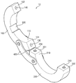
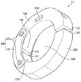
도 1은 본 발명의 일 실시예에 의한 밴드형 배관 누설 검출 장치를 도시한 사시도이다.
도 2는 도 1의 밴드형 배관 누설 검출 장치의 제1 및 제2 밴드부들이 서로 개방된 상태를 도시한 사시도이다.
도 3은 도 1의 밴드형 배관 누설 검출 장치를 도시한 단면도이다.
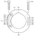
도 4는 도 3의 밴드형 배관 누설 검출 장치를 'A'방향에서 관측한 측단면도이다.
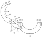
도 5는 도 3의 밴드형 배관 누설 검출 장치의 제1 및 제2 밴드부들이 서로 개방된 상태를 도시한 단면도이다.
도 6은 본 발명의 다른 실시예에 의한 밴드형 배관 누설 검출 장치를 도시한 단면도이다.
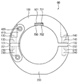
도 7은 본 발명의 또 다른 실시예에 의한 밴드형 배관 누설 검출 장치를 도시한 사시도이다.
도 8은 본 발명의 또 다른 실시예에 의한 밴드형 배관 누설 검출 장치를 도시한 단면도이다.
도 9는 도 1의 밴드형 배관 누설 검출 장치를 이용한 배관 누설 검출 시스템을 도시한 모식도이다.
도 10은 도 9의 배관 누설 검출 시스템에서 'B'부분을 확대한 모식도이다.1 is a perspective view showing a band-type pipe leak detection apparatus according to an embodiment of the present invention.
FIG. 2 is a perspective view illustrating a state in which the first and second band portions of the band type pipe leak detection apparatus of FIG.
3 is a cross-sectional view illustrating the band-type pipe leak detecting apparatus of FIG. 1.
4 is a side cross-sectional view of the band-type pipe leakage detecting device of FIG. 3 observed in the 'A' direction.
5 is a cross-sectional view illustrating a state in which the first and second band portions of the band-type pipe leak detection apparatus of FIG.
6 is a cross-sectional view showing a band-type pipe leak detection apparatus according to another embodiment of the present invention.
7 is a perspective view showing a band-type pipe leak detection apparatus according to another embodiment of the present invention.
8 is a cross-sectional view showing a band-type pipe leak detection apparatus according to another embodiment of the present invention.
FIG. 9 is a schematic diagram illustrating a pipe leak detection system using the band-type pipe leak detection device of FIG. 1.
FIG. 10 is an enlarged schematic view of a portion 'B' in the pipe leakage detection system of FIG. 9.
본 발명은 다양한 변경을 가할 수 있고 여러 가지 형태를 가질 수 있는 바, 실시예들을 본문에 상세하게 설명하고자 한다. 그러나 이는 본 발명을 특정한 개시 형태에 대해 한정하려는 것이 아니며, 본 발명의 사상 및 기술 범위에 포함되는 모든 변경, 균등물 내지 대체물을 포함하는 것으로 이해되어야 한다. 각 도면을 설명하면서 유사한 참조부호를 유사한 구성요소에 대해 사용하였다. 제1, 제2 등의 용어는 다양한 구성요소들을 설명하는데 사용될 수 있지만, 상기 구성요소들은 상기 용어들에 의해 한정되어서는 안 된다. As the inventive concept allows for various changes and numerous modifications, the embodiments will be described in detail in the text. However, this is not intended to limit the present invention to a specific disclosed form, it should be understood to include all modifications, equivalents, and substitutes included in the spirit and scope of the present invention. In describing the drawings, similar reference numerals are used for similar elements. Terms such as first and second may be used to describe various components, but the components should not be limited by the terms.
상기 용어들은 하나의 구성요소를 다른 구성요소로부터 구별하는 목적으로만 사용된다. 본 출원에서 사용한 용어는 단지 특정한 실시예를 설명하기 위해 사용된 것으로, 본 발명을 한정하려는 의도가 아니다. 단수의 표현은 문맥상 명백하게 다르게 뜻하지 않는 한, 복수의 표현을 포함한다. The terms are used only for the purpose of distinguishing one component from another. The terminology used herein is for the purpose of describing particular example embodiments only and is not intended to be limiting of the present invention. Singular expressions include plural expressions unless the context clearly indicates otherwise.
본 출원에서, "포함하다" 또는 "이루어진다" 등의 용어는 명세서상에 기재된 특징, 숫자, 단계, 동작, 구성요소, 부분품 또는 이들을 조합한 것이 존재함을 지정하려는 것이지, 하나 또는 그 이상의 다른 특징들이나 숫자, 단계, 동작, 구성요소, 부분품 또는 이들을 조합한 것들의 존재 또는 부가 가능성을 미리 배제하지 않는 것으로 이해되어야 한다. In this application, the terms "comprise" or "consist of" are intended to indicate that there is a feature, number, step, operation, component, part, or combination thereof described in the specification, and one or more other features. It is to be understood that the present invention does not exclude the possibility of the presence or the addition of numbers, steps, operations, components, parts, or combinations thereof.
다르게 정의되지 않는 한, 기술적이거나 과학적인 용어를 포함해서 여기서 사용되는 모든 용어들은 본 발명이 속하는 기술 분야에서 통상의 지식을 가진 자에 의해 일반적으로 이해되는 것과 동일한 의미를 가지고 있다. 일반적으로 사용되는 사전에 정의되어 있는 것과 같은 용어들은 관련 기술의 문맥 상 가지는 의미와 일치하는 의미를 가지는 것으로 해석되어야 하며, 본 출원에서 명백하게 정의하지 않는 한, 이상적이거나 과도하게 형식적인 의미로 해석되지 않는다.Unless defined otherwise, all terms used herein, including technical or scientific terms, have the same meaning as commonly understood by one of ordinary skill in the art. Terms such as those defined in the commonly used dictionaries should be construed as having meanings consistent with the meanings in the context of the related art and shall not be construed in ideal or excessively formal meanings unless expressly defined in this application. Do not.
이하, 첨부한 도면들을 참조하여, 본 발명의 바람직한 실시예를 보다 상세하게 설명하고자 한다.Hereinafter, with reference to the accompanying drawings, it will be described in detail a preferred embodiment of the present invention.
도 1은 본 발명의 일 실시예에 의한 밴드형 배관 누설 검출 장치를 도시한 사시도이다. 도 2는 도 1의 밴드형 배관 누설 검출 장치의 제1 및 제2 고리부들이 서로 개방된 상태를 도시한 사시도이다. 도 3은 도 1의 밴드형 배관 누설 검출 장치를 도시한 단면도이다. 도 4는 도 3의 밴드형 배관 누설 검출 장치를 도시한 측단면도이다.1 is a perspective view showing a band-type pipe leak detection apparatus according to an embodiment of the present invention. FIG. 2 is a perspective view illustrating a state in which the first and second annular portions of the band-type pipe leak detection apparatus of FIG. 1 are opened to each other. 3 is a cross-sectional view illustrating the band-type pipe leak detecting apparatus of FIG. 1. 4 is a side cross-sectional view showing the band-type pipe leak detection apparatus of FIG.
우선, 도 1 및 도 2를 참조하면, 본 실시예에 의한 밴드형 배관 누설 검출 장치(10)는 제1 및 제2 밴드부들(100, 200), 및 체결수단(400)을 포함한다.First, referring to FIGS. 1 and 2, the band-type pipe
상기 제1 및 제2 밴드부들(100, 200)은 도시된 바와 같이 만곡된 원호 형상으로 형성되며, 각각의 제1 끝단부들(101, 201)이 서로 소정 거리 이격되며 마주보도록 위치한 상태에서 각각의 일단부들(110, 210)이 체결수단(400)을 통해 서로 연결된다. The first and
이 경우, 상기 제1 및 제2 밴드부들(100, 200)은 상기 각각의 일단부들(110, 210)을 중심으로 각각의 제2 끝단부들(102, 202)이 서로 마주보도록 회전하여 내부에 중공부(300)가 형성된 전체적으로 링(ring) 형상을 형성할 수 있다. In this case, the first and
상기 제1 및 제2 밴드부들(100, 200)은 상기 중공부(300)를 통해 누설 검출 여부의 대상이 되는 배관(미도시)의 외주연에 끼워져 상기 배관의 누설 여부를 판단할 수 있으며, 앞서 설명한 바와 같이 각각이 만곡된 형상으로 형성됨으로써 상기 배관 표면에 보다 더 밀착될 수 있다. The first and
한편, 상기 밴드형 배관 누설 검출 장치(10)는 배관에 결합된 상태에서 유지 보수가 필요하여 상기 배관으로부터 탈착이 필요한 경우에는, 도 2에 도시된 바와 같이 상기 제1 및 제2 밴드부들(100, 200) 각각이 상기 각각의 일단부(110, 210)를 중심으로 상기 각각의 제2 끝단부(102, 202)가 서로 멀어지는 방향으로 회전하도록 함으로써 상기 배관으로부터 탈착될 수 있다.On the other hand, when the band-type pipe
이 경우, 상기 제1 및 제2 밴드부들(100, 200) 각각은 원호 방향의 일부가 개방 되어 있는 형태로서, 상기 각각의 일단부(110, 210)만이 연결된 상태에서 서로 개방(open)될 수 있다.In this case, each of the first and
한편, 상기 체결수단(400)은 앞서 설명한 바와 같이 상기 제1 및 제2 밴드부들(100, 200) 각각의 일단부(110, 210)를 서로 연결시키며, 연결부재(410) 및 나사체결부재(420)를 포함한다. Meanwhile, as described above, the fastening means 400 connects the
또한, 상기 체결수단(400)은 도시된 바와 같이 한 쌍으로 형성되어 상기 제1 및 제2 밴드부들(100, 200)의 일측 및 타측에 서로 마주보도록 위치하여 상기 제1 밴드부(100) 및 상기 제2 밴드부(200)를 서로 고정시킴으로써 고정력을 더욱 향상시킬 수 있다. In addition, the fastening means 400 is formed as a pair as shown to be positioned to face each other on one side and the other side of the first and second band portions (100, 200) the
상기 연결부재(410)는 상기 제1 및 제2 밴드부들(100, 200) 각각의 일단부(110, 210)에 결합되며 상기 제1 및 제2 밴드부들(100, 200) 각각의 일단부(110, 210) 사이에 연장되어 상기 제1 및 제2 밴드부들(100, 200) 각각의 일단부(110, 210)를 서로 연결시킨다.The
이 경우, 상기 제 1 및 제2 밴드부들(100, 200) 각각이 각각의 제1 끝단부들(101, 201)을 중심으로 회전하여 각각의 상기 제2 끝단부들(102, 202)이 서로 멀어지거나 가까워지는 방향으로 용이하게 회전할 수 있도록, 상기 연결부재(410)는 상기 제1 및 제2 밴드부들(100, 200) 각각의 상기 제1 끝단부들(101, 201)이 서로 소정 거리 이격된 상태에서 상기 제1 및 제2 밴드부들(100, 200) 각각의 일단부(110, 210)와 결합하며, 나아가, 상기 제1 밴드부(100) 및 제2 밴드부(200) 각각의 일단부(110, 210)와 유사한 형상으로 형성될 수 있다. 즉, 상기 연결부재(410)는 상기 제1 및 제2 밴드부들(100, 200)의 일단부와 같은 원호 형상으로 형성될 수 있다. In this case, each of the first and
상기 나사체결부재(420)는 상기 연결부재(410)를 상기 제1 및 제2 밴드부들(100, 200) 각각의 일단부(110, 210)에 결합시키는 역할을 한다. 즉, 상기 나사체결부재(420)는 상기 연결부재(410)에 형성된 관통홀(미도시)과 상기 제1 및 제2 밴드부들(100, 200) 각각의 일단부(110, 210)에 상기 관통홀과 마주보도록 형성된 체결공(미도시)에 관통 삽입되어 상기 연결부재(410)를 상기 제1 및 제2 밴드부들(100, 200)에 결합시킬 수 있다.The
한편, 도 2에 도시된 바와 같이, 상기 제1 밴드부(100)의 제1 끝단(101)에는 제1 관통공(130)이 형성되고 상기 제1 밴드부(100)의 제2 끝단(102)에는 제3 관통공(140)이 형성되며, 상기 제2 밴드부(200)의 제1 끝단(201)에는 제2 관통공(230)이 형성되고 상기 제2 밴드부(200)의 제2 끝단(202)에는 제4 관통공(240)이 형성된다.Meanwhile, as shown in FIG. 2, a first through
이 경우, 도 3 및 도 4를 참조하면, 제1 고정부재(610)가 상기 제1 및 제2 관통공들(130, 230)을 관통하여 상기 제1 및 제2 밴드부들(100, 200) 각각의 제1 끝단(101, 201)을 서로 고정시킬 수 있으며, 제2 고정부재(620)가 상기 제3 및 제4 관통공들(140, 240)을 관통하여 상기 제1 및 제2 밴드부들(100, 200) 각각의 제2 끝단(102, 202)을 서로 고정시킬 수 있다.In this case, referring to FIGS. 3 and 4, the first fixing member 610 penetrates the first and second through
나아가, 상기 제1 및 제2 고정부재들(610, 620)은 상기 제1 및 제2 밴드부(100, 200)들 각각의 제1 끝단부들(101, 201)이 서로 소정 간격으로 갭(gap)을 형성하도록 하고 각각의 제2 끝단부들(102, 202)도 동일한 간격으로 갭을 형성하도록 한 후, 상기 제1 밴드부(100) 및 상기 제2 밴드부(200)를 서로 고정시킬 수 있다.Further, the first and second fixing
즉, 상기 밴드형 배관 누설 검출 장치(10)는 배관의 직경에 따라 상기 갭의 간격 조정이 가능하며, 갭의 간격을 조정한 후 상기 제1 및 제2 고정부재들(610, 620)을 이용하여 상기 제1 및 제2 밴드부들(100, 200)을 배관에 고정시킬 수 있으므로 보다 다양한 직경을 가지는 배관에 적용될 수 있다. That is, the band type pipe
한편, 상기와 같이 상기 제1 및 제2 밴드부들(100, 200)이 서로 고정된 상태에서, 상기 제1 고정부재(610)를 상기 제1 및 제3 관통공들(130, 230)로 부터 분리시키고, 상기 제2 고정부재(620)를 상기 제2 및 제4 관통공들(140, 240)로부터 분리시켜 상기 제1 및 제2 밴드부들(100, 200) 각각을 회전시킴으로써 도 5에 도시된 바와 같이 상기 제1 및 제2 밴드부들(100, 200)을 서로 개방시킬 수 있다.Meanwhile, the first fixing member 610 from the first and third through
다시 도 1 및 도 2를 참조하면, 상기 제1 밴드부(100)의 내주면에는 소정 깊이를 형성하는 오목한 홈부(500)가 형성될 수 있다. 상기 홈부(500)는 상기 제1 밴드부(100)의 내주면에 수용 공간을 형성하여 누설감지센서(미도시)가 상기 수용 공간에 위치되도록 할 수 있다.Referring back to FIGS. 1 and 2, a
그리하여, 앞서 설명한 바와 같이 상기 제1 및 제2 밴드부들(100, 200)이 전체적으로 링 형상을 형성하여 배관에 고정되는 경우, 상기 누설감지센서가 상기 배관의 누설 여부를 감지할 수 있다.Thus, as described above, when the first and
이 경우, 상기 누설감지센서가 상기 수용 공간에 위치한 상태에서 상기 배관에 접촉하여 상기 배관의 누설 여부를 감지할 수 있도록, 상기 수용 공간의 깊이는 상기 누설감지센서의 형상, 크기, 구조 등을 고려하여 형성하는 것이 바람직하다.In this case, the depth of the accommodating space takes into account the shape, size, structure, etc. of the leak detecting sensor so that the leak detecting sensor can be in contact with the pipe in a state where the leak detecting sensor is located in the accommodating space. It is preferable to form.
또한, 상기 홈부(500)의 일 측면(501)은 도시된 바와 같이 플레이트(plate) 형상으로 형성되어, 도시하지 않았으나 일측면이 플레이트 형상으로 형성된 상기 누설감지센서가 상기 홈부(500)의 상기 일 측면(501)과 접하며 상기 홈부(500)의 수용 공간에 위치되도록 할 수 있다.In addition, one
상기 누설감지센서는 접촉압력센서, 변형률센서, 온도센서 중 적어도 어느 하나일 수 있으며, 이에 한정되지 않고 배관 누설 여부를 감지할 수 있는 센서들은 상기 누설감지센서로서 모두 사용이 가능하다.The leak detection sensor may be at least one of a contact pressure sensor, a strain sensor, and a temperature sensor, and the present disclosure is not limited thereto, and any sensors capable of detecting pipe leakage may be used as the leak detection sensor.
예를 들어, 상기 누설감지센서가 접촉압력센서인 경우, 상기 접촉압력센서는 배관과 밴드부 사이의 접촉 압력을 계측하여 배관 내부의 유체의 압력을 검출하고, 검출된 유체의 압력에 대한 압력 검출 신호를 외부 장치(미도시)로 출력한다. 예를 들면, 배관 내부의 유체의 압력이 증가할 경우 밴드와 배관 사이의 접촉압력이 증가하고, 배관 내부의 유체의 압력이 감소할 경우 밴드와 배관 사이의 접촉압력이 감소한다. For example, when the leak detection sensor is a contact pressure sensor, the contact pressure sensor measures the contact pressure between the pipe and the band part to detect the pressure of the fluid in the pipe, and a pressure detection signal for the detected pressure of the fluid. Outputs to an external device (not shown). For example, when the pressure of the fluid inside the pipe increases, the contact pressure between the band and the pipe increases, and when the pressure of the fluid inside the pipe decreases, the contact pressure between the band and the pipe decreases.
이 경우, 상기 접촉압력센서는 상기 홈부(500)의 상기 일 측면(501) 및 상기 배관의 외면에 접함으로써 상기 밴드부와 상기 배관 사이의 압력을 계측할 수 있게 된다. In this case, the contact pressure sensor can measure the pressure between the band portion and the pipe by contacting the one
또한, 배관 내 누설이 발생하지 않은 경우 상기 압력 검출 신호의 출력값에 큰 변화가 없으나, 상기 배관에 누설이 발생한 경우에는 상기 압력 검출 신호의 출력값에 뚜렷한 변화가 생기게 된다.In addition, when there is no leakage in the pipe, there is no significant change in the output value of the pressure detection signal. However, when leakage occurs in the pipe, a clear change occurs in the output value of the pressure detection signal.
그리하여 사용자는 상기 외부 장치를 통해 상기 배관 내부의 누설 여부를 판단할 수 있게 된다.Thus, the user can determine whether the inside of the pipe leaks through the external device.
다른 예로, 상기 누설감지센서가 온도센서인 경우, 상기 온도센서는 상기 홈부(500)에 위치된 상태에서 상기 배관의 온도를 감지하고 감지된 온도에 대한 온도 검출 신호를 외부 장치로 출력한다.As another example, when the leak detection sensor is a temperature sensor, the temperature sensor detects the temperature of the pipe in a state positioned in the
이 경우, 마찬가지로 고온 또는 저온의 가스 또는 유체가 상기 배관의 손상이 있는 부분으로 새어나올 경우 상기 온도 검출 신호의 출력값에 뚜렷한 변화가 생기게 되며, 사용자는 이를 통해 상기 배관 내부의 누설 여부를 판단할 수 있게 된다.In this case, similarly, when a high temperature or low temperature gas or fluid leaks out to the damaged part of the pipe, a distinct change occurs in the output value of the temperature detection signal, and the user can determine whether the inside of the pipe is leaked. Will be.
이상과 같은 상기 밴드형 배관 누설 검출 장치(10)는 하수관 또는 수도관 등의 다양한 매설배관에 적용될 수 있고, 지압 또는 지반 침하 등의 충격에 찌그러지기 쉬운 연성관 타입의 하수관에 적용될 수도 있다.The band-type pipe
한편, 도 1에 도시한 것과 같이 하나의 상기 홈부(500)를 상기 제1 밴드부(100)에 형성되는 것으로 도시하였으나, 상기 홈부(500)는 상기 제2 밴드부(200)에 형성될 수 있으며, 복수개로 형성되어 상기 제1 밴드부(100) 또는 상기 제2 밴드부(200)에 형성될 수 있고 상기 제1 및 제2 밴드부(100, 200)에 모두 형성될 수도 있다.Meanwhile, as illustrated in FIG. 1, one
이와 같이 상기 홈부(500)가 복수개로 형성되는 경우, 각각의 홈부(500)에 형성되는 누설감지센서를 통해 배관 누설 여부의 정확도를 향상시킬 수 있으며, 나아가 각각의 홈부(500)에 다양한 종류의 누설감지센서를 위치시킬 수 있어 다양한 종류의 누설감지센서를 통해 배관 누설 여부를 감지함으로써 배관 누설 여부의 정확도를 더욱 향상시킬 수 있다.As described above, when the
도 6은 본 발명의 다른 실시예에 의한 밴드형 배관 누설 검출 장치를 도시한 사시도이다.6 is a perspective view showing a band-type pipe leak detection apparatus according to another embodiment of the present invention.
본 실시예에 의한 밴드형 배관 누설 검출 장치(60)는 상기 홈부에 배관의 외면과 접촉하는 블록(block)이 형성되는 것을 제외하고는 도 1 내지 도 5를 참조하여 설명한 상기 밴드형 배관 누설 검출 장치(10)와 동일하므로, 동일한 참조번호를 사용하고 중복되는 설명은 생략한다.In the band-type pipe
앞서 설명한 바와 같이 상기 누설감지센서가 접촉압력센서인 경우, 상기 접촉압력센서는 배관과 밴드부 사이의 접촉 압력을 계측을 통해 상기 배관의 누설 여부를 감지할 수 있다.As described above, when the leak detection sensor is a contact pressure sensor, the contact pressure sensor may detect whether the pipe is leaking by measuring the contact pressure between the pipe and the band part.
이와 같이 상기 접촉압력센서가 배관의 누설 여부를 감지하기 위해서는 접촉 압력이 발생하여야 한다.Thus, in order for the contact pressure sensor to detect the leakage of the pipe, a contact pressure must be generated.
따라서, 상기 접촉압력센서가 크기 등으로 인해 상기 홈부에 위치하나, 상기 제1 및/또는 제2 밴드부의 내주면 및 상기 배관의 외면과 동시에 접촉되지 않을 경우, 도 6에 도시된 바와 같이 상기 홈부(500)에 배관(1)의 외면과 접촉하는 블록(700)을 형성할 수 있다.Therefore, when the contact pressure sensor is located in the groove part due to the size or the like, but is not simultaneously in contact with the inner circumferential surface of the first and / or second band part and the outer surface of the pipe, as shown in FIG. 6, the groove part ( A
이 경우, 상기 블록(700)의 크기, 구조 등은 상기 접촉압력센서가 상기 홈부(500)에 위치하며 상기 제1 및/또는 제2 밴드부(100, 200)의 내주면 및 상기 블록(700)과 동시에 접촉할 수 있도록, 상기 홈부(500)의 폭 및 높이, 상기 접촉압력센서의 크기 등을 고려하여 형성할 수 있다.In this case, the size, structure, and the like of the
또한, 앞서 설명한 바와 같이 상기 홈부(500)의 상기 일 측면(501)은 플레이트 형상으로 형성되고 상기 배관(1)은 원통 형상으로 형성되므로, 상기 블록(700)의 상단면(701)은 상기 일 측면(501)과 접하도록 플레이트 형상으로 형성되고 하단면(702)은 상기 배관(1)의 외면과 접하도록 굴곡진 형상으로 형성될 수 있다.In addition, as described above, the one
이 경우, 상기 접촉압력센서는 상기 블록(700)의 상기 상단면(701)과 상기 홈부(500)의 상기 일 측면(501) 사이에 형성된 갭(gap)에 끼워질 수 있으며, 그리하여 상기 접촉압력센서는 상기 제1 및/또는 제2 밴드부(100, 200)의 내주면과 상기 블록(700) 사이의 접촉 압력을 계측하여 상기 배관(1) 내부의 유체의 압력을 검출하고, 이를 통해 상기 배관(1)의 누설 여부를 감지할 수 있게 된다.In this case, the contact pressure sensor may be fitted into a gap formed between the
한편, 상기 접촉압력센서에서 계측되는 상기 접촉 압력은 상기 배관(1) 내 압력, 상기 배관(1)의 직경, 상기 제1 및/또는 제2 밴드부(100, 200)의 직경, 상기 배관(1)과 상기 제1 및/또는 제2 밴드부(100, 200)의 재질, 상기 배관(1)과 상기 제1 및/또는 제2 밴드부(100, 200)의 두께 등에 따라 변화될 수 있다.The contact pressure measured by the contact pressure sensor may include a pressure in the
도 7은 본 발명의 또 다른 실시예에 의한 밴드형 배관 누설 검출 장치를 도시한 사시도이다.7 is a perspective view showing a band-type pipe leak detection apparatus according to another embodiment of the present invention.
본 실시예에 의한 밴드형 배관 누설 검출 장치(70)는 상기 홈부가 홀의 형태로 상기 제1 밴드부(100)의 중앙을 관통하도록 형성된 것을 제외하고는 도 1 내지 도 5를 참조하여 설명한 상기 밴드형 배관 누설 검출 장치(10)와 동일하므로, 동일한 참조번호를 사용하고 중복되는 설명은 생략한다.The band type pipe
도 7을 참조하면, 본 실시예에서는 도시된 바와 같이 상기 제1 밴드부(100)의 내부에는 상기 제1 밴드부(100)의 중앙부를 관통하도록 홀(510)이 형성된다. Referring to FIG. 7, as shown in the present embodiment, a
이 경우, 앞서 설명한 상기 누설감지센서는 상기 홀(510)에 위치되어 상기 밴드형 배관 누설 검출 장치(70)가 배관에 결합되는 경우에 배관의 누설을 감지할 수 있게 된다.In this case, the leak detection sensor described above may be located in the
이 때, 상기 홀(510)의 도시된 바와 같은 일 측면(511) 및 타 측면(512)은 플레이트 형상으로 형성되며, 단면이 플레이트 형상으로 형성되는 누설감지센서가 상기 홀(510)의 내부에 삽입되며 상기 일 측(511) 및 상기 타 측면(512)과 접하도록 할 수 있다. At this time, one
보다 구체적으로, 상기 누설감지센서가 변형률센서인 경우, 상기 변형률 센서는 상기 홀(510)에 위치하여 상기 홀(510)의 상기 일 측면(511) 및 상기 타 측면(512)과 접하게 되며, 누설에 따른 배관 내 압력 감소에 따라 변화하는 제1 및/또는 제2 밴드부(100, 200)의 변형률 변화를 감지하여 배관 내 압력을 예측할 수 있으며 이를 바탕으로 배관의 누설 여부를 판단할 수 있게 된다.More specifically, when the leak detection sensor is a strain sensor, the strain sensor is located in the
나아가, 상기 누설감지센서가 온도센서인 경우, 상기 온도센서도 마찬가지로 상기 홀(510)에 위치될 수 있으며, 이 경우 상기 온도센서는 누설에 따른 배관주위의 온도 변화를 감지하여 배관의 누설 여부를 판단할 수 있게 된다.Furthermore, when the leak detection sensor is a temperature sensor, the temperature sensor may be located in the
더 나아가, 도시하지 않았으나 상기 홀(510)은 상기 제2 밴드부(200)에도 형성될 수 있으며, 복수개로 형성되어 상기 제1 밴드부(100) 또는 상기 제2 밴드부(200)에 형성될 수 있고 상기 제1 및 제2 밴드부(100, 200)에 모두 형성될 수도 있다.Furthermore, although not shown, the
도 8은 본 발명의 또 다른 실시예에 의한 밴드형 배관 누설 검출 장치를 도시한 단면도이다.8 is a cross-sectional view showing a band-type pipe leak detection apparatus according to another embodiment of the present invention.
본 실시예에 의한 밴드형 배관 누설 검출 장치(80)는 상기 홀에 블록이 형성되는 것을 제외하고는 도 7을 참조하여 설명한 상기 밴드형 배관 누설 검출 장치(70)와 동일하므로, 동일한 참조번호를 사용하고 중복되는 설명은 생략한다.Since the band-type pipe
도 7을 참조하면, 상기 홀(510)은 도시된 바와 같이 일 측면(511) 및 타 측면(512)이 플레이트한 형상으로 형성되므로, 상기 블록(710)은 상단면(711)이 상기 홀(510)의 상기 일 측면(511)에 접하고 하단면(712)이 상기 홀(510)의 상기 타 측면(512)에 접하도록, 상기 상단면(711) 및 상기 하단면(712)이 플레이트 형상으로 형성될 수 있다.Referring to FIG. 7, since the
이에 따라, 상기 홀(510)의 상기 일 측면(511)과 상기 블록(710)의 상기 상단면(711) 사이에 형성된 갭 또는 상기 홀(510)의 상기 타 측면(512)과 상기 블록(710)의 상기 하단면(712) 사이에 형성된 갭에 상기 누설감지센서가 끼워져 상기 밴드부와 상기 블록(710)과 접촉하거나 상기 블록(710)과 상기 배관(1)과 접촉하여 상기 배관의 누설 여부를 판단할 수 있게 된다.Accordingly, a gap formed between the one
도 8은 도 1의 밴드형 배관 누설 검출 장치를 이용한 배관 누설 검출 시스템을 도시한 모식도이다. 도 9는 도 8의 배관 누설 검출 시스템에서 'B'부분을 확대한 모식도이다.FIG. 8 is a schematic diagram illustrating a pipe leak detection system using the band-type pipe leak detection device of FIG. 1. 9 is an enlarged schematic view of a portion 'B' in the pipe leakage detection system of FIG. 8.
도 8 및 도 9를 참조하면, 본 실시예에 의한 배관 누설 검출 시스템(20)은 배관(1)에서 누설이 발생하면 밸브(30) 중 누설된 부분과 인접한 밸브(30)를 최우선으로 차단할 수 있으며, 상기 배관(1)에 끼워진 적어도 하나 이상의 상기 밴드형 배관 누설 검출 장치(10)를 통해 배관의 누설된 위치를 검출할 수 있다. 8 and 9, when a leak occurs in the
상기 밴드형 배관 누설 검출 장치(10)는 누설감지센서(11)가 접촉압력센서인 경우, 상기 누설감지센서(11)를 통해 상기 배관(1)의 압력을 감지할 수 있으며, 상기 배관(1)의 외면에 복수의 밴드형 배관 누설 검출 장치(10)가 고정된 경우 각각의 밴드형 배관 누설 검출 장치(10)의 누설감지센서(11)를 통해 측정한 압력값을 고려하여 상기 배관(1)에서 누설된 부분의 위치를 용이하게 검출할 수 있다.The band-type pipe
또한, 누설된 배관에서의 상기 누설감지센서(11)에 의해 검출된 압력값을 누설되지 않은 배관의 기준 설정 값과의 차이를 비교하여 누설된 배관의 누설 정도까지 파악할 수 있다.In addition, the pressure value detected by the
상기 배관(1)은 예를 들면 발전소 등에서 고온의 스팀, 유체 등을 이송하기 위한 배관일 수 있다.The
보다 구체적으로, 상기 배관 누설 검출 시스템(20)은 적어도 하나 이상의 상기 밴드형 배관 누설 검출 장치(10), 제어부(12), 데이터 전송부(13) 및 외부 장치(50)를 포함한다. More specifically, the pipe
상기 배관(1)에는 복수의 밴드형 배관 누설 검출 장치들이 고정되며, 상기 복수의 밴드형 배관 누설 검출 장치들은 상기 배관(1)에서 각각이 고정된 부분에서의 압력을 검출한다.A plurality of band type pipe leak detection devices are fixed to the
복수의 밴드형 배관 누설 검출 장치들 중 어느 하나의 밴드형 배관 누설 검출 장치(10)에서 검출한 압력값이 기설정된 압력값과 다른 경우, 상기 제어부(12)는 누설된 배관에 관한 정보를 수집하며, 이를 후술하는 외부 장치(50)에서 수신할 수 있도록 변환한다. When the pressure value detected by any one of the band-type pipe
이 경우, 상기 밴드형 배관 누설 검출 장치(10)의 위치를 알 수 있으므로 상기 배관(1)에서 상기 밴드형 배관 누설 검출 장치(10)가 고정된 부분의 위치 또한 알 수 있으며, 이에 따라 상기 제어부(12)에서 수집하는 상기 누설된 배관에 관한 정보에는 누설된 배관의 누설 위치에 관한 정보가 포함될 수 있다.In this case, since the position of the band-type pipe
상기 데이터 전송부(13)는 이와 같이 상기 제어부(12)에서 수집 및 변환한 상기 누설된 배관에 관한 정보를 상기 외부 장치(50)로 무선으로 전송한다.The
그러면 사용자는 상기 외부 장치(50)를 통해 상기 배관(1)에서의 누설 여부 및 누설 위치를 파악할 수 있게 된다.Then, the user can determine whether the leakage in the
본 발명의 실시예들에 의하면, 제1 및 제2 밴드부들은 링(ring) 형태로 서로 결합하거나 회전을 통해 서로 개방될 수 있어 배관의 외면에 탈부착이 가능하여, 배관에 용이하게 고정할 수 있음은 물론 유지보수가 필요한 경우 배관으로부터 용이하게 분리될 수 있다.According to the embodiments of the present invention, the first and second band parts may be coupled to each other in a ring form or may be opened to each other by rotation, so that the first and second band parts may be detachably attached to the outer surface of the pipe, thereby being easily fixed to the pipe. Of course, it can be easily separated from the pipe when maintenance is required.
또한, 제1 및/또는 제2 밴드부들의 내측면에 형성된 홈부에 누설감지센서를 위치시키는 경우, 상기 누설감지센서 중 접촉압력센서와 변형률센서는 배관 내 유동압력의 변화를 감지하고, 온도센서는 주위 온도 변화를 감지하여 누설 여부를 용이하게 파악할 수 있다. In addition, when the leak detection sensor is located in the groove formed on the inner side of the first and / or second band portion, the contact pressure sensor and the strain sensor of the leak detection sensor detects the change in the flow pressure in the pipe, the temperature sensor By detecting changes in ambient temperature, it is easy to identify leaks.
나아가, 배관의 외면에 복수의 밴드형 배관 누설 검출 장치를 고정시켜, 복수의 밴드형 배관 누설 검출 장치들 중 측정값이 다른 밴드형 배관 누설 검출 장치를 검출할 수 있으므로, 밴드형 배관 누설 검출 장치의 위치를 통해 배관의 누설된 부위의 위치를 알 수 있으며 그 누설 정도를 정확하게 검사할 수 있다.Furthermore, a plurality of band-type pipe leak detection devices can be fixed to the outer surface of the pipe to detect a band-type pipe leak detection device having a different measured value among the plurality of band-type pipe leak detection devices. The location of the pipe can identify the location of the leaked part of the pipe and can accurately check the degree of leakage.
상기에서는 본 발명의 바람직한 실시예를 참조하여 설명하였지만, 해당 기술 분야의 숙련된 당업자는 하기의 특허 청구 범위에 기재된 본 발명의 사상 및 영역으로부터 벗어나지 않는 범위 내에서 본 발명을 다양하게 수정 및 변경시킬 수 있음을 이해할 수 있을 것이다.While the foregoing has been described with reference to preferred embodiments of the present invention, those skilled in the art will be able to variously modify and change the present invention without departing from the spirit and scope of the invention as set forth in the claims below. It will be appreciated.
100 : 제1 밴드부
200 : 제2 밴드부
101, 201 : 제1 끝단부
102, 202 : 제2 끝단부
110, 210 : 일단부
300 : 중공부
400 : 체결수단
410 : 연결부재
420 : 나사체결부재
500 : 홈부
510 : 홀
700, 710 : 블록100: first band portion 200: second band portion
101, 201:
110, 210: one end 300: hollow part
400: fastening means 410: connecting member
420: screw fastening member 500: groove
510:
Claims (13)
각각의 일단부가 서로 연결되고, 상기 일단부를 중심으로 회전하여 서로 링(ring) 형상으로 상기 배관에 탈착 가능하도록 결합하는 제1 및 제2 밴드부들;
상기 제1 및 제2 밴드부들 각각의 일단부에 결합되어 상기 제1 및 제2 밴드부들을 연결하는 체결수단; 및
상기 제1 및/또는 제2 밴드부의 내부에 위치하여 상기 배관의 누설을 감지하는 누설감지센서를 포함하는 배관 누설 검출 장치. In the pipe leak detection device fixed to the pipe for detecting the leak of the pipe,
First and second band portions having one end connected to each other and rotatably coupled to the one end to be detachably coupled to the pipe in a ring shape;
Fastening means coupled to one end of each of the first and second band portions to connect the first and second band portions; And
Pipe leak detection apparatus including a leak detection sensor to be located inside the first and / or second band portion to detect the leakage of the pipe.
상기 제1 및 제2 밴드부들 각각의 일단부 사이에 연장되는 연결부재; 및
상기 연결부재를 관통하여 상기 제1 및 제2 밴드부들 각각의 일단부에 형성된 체결공에 삽입되는 나사체결부재를 포함하는 것을 특징으로 하는 배관 누설 검출 장치.The method of claim 1, wherein the fastening means,
A connection member extending between one end of each of the first and second band portions; And
And a screw fastening member inserted into a fastening hole formed at one end of each of the first and second band portions through the connection member.
상기 제1 및 제2 밴드부들 각각의 제1 끝단에 서로 마주보도록 위치하며 관통된 제1 및 제2 관통공들이 각각 형성되고,
상기 제1 및 제2 밴드부들 각각의 제2 끝단에 서로 마주보도록 위치하며 관통된 제3 및 제4 관통공들이 각각 형성되는 것을 특징으로 하는 배관 누설 검출 장치.The method of claim 1,
First and second through-holes are formed to face each other at the first end of each of the first and second band portions, respectively,
Pipe leakage detection device, characterized in that the third and fourth through holes are positioned to face each other at the second end of each of the first and second band portion are formed.
상기 제1 및 제2 관통공들을 관통하여 상기 제1 및 제2 밴드부들 각각의 제1 끝단을 서로 고정시키는 제1 고정부재; 및
상기 제3 및 제4 관통공을 관통하여 상기 제1 및 제2 밴드부들 각각의 제2 끝단을 서로 고정시키는 제2 고정부재를 더 포함하는 배관 누설 검출 장치.The method of claim 3,
A first fixing member penetrating the first and second through holes to fix the first ends of each of the first and second band portions to each other; And
And a second fixing member penetrating the third and fourth through holes to fix the second ends of each of the first and second band portions to each other.
상기 제1 및 제2 밴드부들은 서로 소정 간격으로 갭을 형성하며, 상기 갭은 배관의 직경에 따라 조정되는 것을 특징으로 하는 배관 누설 검출 장치.The method of claim 4, wherein
And the first and second band portions form a gap at a predetermined interval from each other, and the gap is adjusted according to the diameter of the pipe.
접촉압력센서, 변형률센서, 온도센서 중 어느 하나인 것을 특징으로 하는 배관 누설 검출 장치. The method of claim 1, wherein the leak detection sensor,
Pipe leakage detection device, characterized in that any one of contact pressure sensor, strain sensor, temperature sensor.
상기 누설감지센서는 상기 제1 및/또는 제2 밴드부의 내주면에 형성되며 일 측면이 플레이트 형상으로 형성되는 홈부에 위치하는 것을 특징으로 하는 배관 누설 검출 장치.The method of claim 1,
The leak detection sensor is a pipe leakage detection device, characterized in that located on the inner peripheral surface of the first and / or second band portion is located in the groove portion having one side is formed in a plate shape.
상기 홈부의 내부에는 상기 홈부의 일 측면과 접하도록 상단면이 플레이트 형상으로 형성되고 상기 배관의 외면과 접하도록 하단면이 굴곡지게 형성된 블록(block)이 위치되는 것을 특징으로 하는 배관 누설 검출 장치.The method of claim 7, wherein
The inside of the groove portion is a pipe leakage detection device, characterized in that the upper surface is formed in a plate shape so as to contact with one side of the groove portion and the lower surface is formed to be curved to contact the outer surface of the pipe.
상기 홈부의 일 측면 및 상기 블록의 상단면 사이의 갭에 위치되어, 상기 홈부의 일 측면 및 상기 블록의 상단면과 접촉되는 것을 특징으로 하는 배관 누설 검출 장치.The method of claim 8, wherein the leak detection sensor,
And a gap between the one side of the groove and the top surface of the block, wherein the pipe leakage detection device is in contact with one side of the groove and the top surface of the block.
상기 누설감지센서는 상기 제1 및/또는 제2 밴드부의 내부에 형성되며, 일 측면 및 타측면이 플레이트 형상으로 형성되는 홀(hole)에 위치하는 것을 특징으로 하는 배관 누설 검출 장치. The method of claim 1,
The leak detection sensor is formed in the first and / or second band portion, the pipe leakage detection device, characterized in that located in the hole (hole) formed in one side and the other side of the plate shape.
상기 홀의 내부에는 상기 홀의 일 측면과 접하도록 상단면이 플레이트 형상으로 형성되고 상기 홀의 타 측면과 접하도록 하단면이 플레이트 형상으로 형성된 블록이 위치되는 것을 특징으로 하는 배관 누설 검출 장치.The method of claim 10,
The inside of the hole is a pipe leakage detection device, characterized in that the upper surface is formed in a plate shape to contact with one side of the hole and the bottom surface is formed in a plate shape to contact the other side of the hole.
상기 홀의 일 측면 및 상기 블록의 상단면 사이의 갭에 위치되거나, 또는 상기 홀의 타 측면 및 상기 블록의 하단면 사이의 갭에 위치되는 것을 특징으로 하는 배관 누설 검출 장치.The method of claim 11, wherein the leak detection sensor,
And a gap located between one side of the hole and an upper end surface of the block, or a gap between the other side of the hole and the lower end surface of the block.
상기 배관에서 누설이 발생하는 경우 누설된 배관에 관한 정보를 수집 및 변환하는 제어부; 및
상기 제어부에서 수집 및 변환한 배관에 관한 정보를 외부 장치로 전송하는 데이터 전송부를 포함하고,
상기 배관 누설 검출장치는,
각각의 일단부가 서로 연결되고, 상기 일단부를 중심으로 회전하여 서로 링(ring) 형상으로 상기 배관에 탈착 가능하도록 결합하는 제1 및 제2 밴드부들;
상기 제1 및 제2 밴드부들 각각의 일단부에 결합되어 상기 제1 및 제2 밴드부들을 연결하는 체결수단; 및
상기 제1 및/또는 제2 밴드부의 내부에 위치하여 상기 배관의 누설을 감지하는 누설감지센서를 포함하는 것을 특징으로 하는 배관 누설 검출 시스템. A pipe leak detection device fixed to a pipe to detect a leak of the pipe;
A controller for collecting and converting information about the leaked pipe when a leak occurs in the pipe; And
It includes a data transmission unit for transmitting the information about the piping collected and converted by the control unit to an external device,
The pipe leak detection device,
First and second band portions having one end connected to each other and rotatably coupled to the one end to be detachably coupled to the pipe in a ring shape;
Fastening means coupled to one end of each of the first and second band portions to connect the first and second band portions; And
And a leak detection sensor positioned inside the first and / or second band part to detect a leak of the pipe.
Priority Applications (4)
| Application Number | Priority Date | Filing Date | Title |
|---|---|---|---|
| KR1020180061498A KR102106823B1 (en) | 2018-05-30 | 2018-05-30 | Band type pipe leakage detecting apparatus and pipe leakage detecting method using the same |
| CN201980036320.3A CN112204367B (en) | 2018-05-30 | 2019-05-30 | Pipe damage detection apparatus, pipe damage detection system using the same, and pipe damage detection method using the same |
| PCT/KR2019/006489 WO2019231251A1 (en) | 2018-05-30 | 2019-05-30 | Pipe damage detection apparatus, pipe damage detection system using same and pipe damage detection method using same |
| JP2020566680A JP7139458B2 (en) | 2018-05-30 | 2019-05-30 | PIPE DAMAGE DETECTION DEVICE, PIPE DAMAGE DETECTION SYSTEM USING THE SAME, AND PIPE DAMAGE DETECTION METHOD USING THE SAME |
Applications Claiming Priority (1)
| Application Number | Priority Date | Filing Date | Title |
|---|---|---|---|
| KR1020180061498A KR102106823B1 (en) | 2018-05-30 | 2018-05-30 | Band type pipe leakage detecting apparatus and pipe leakage detecting method using the same |
Publications (2)
| Publication Number | Publication Date |
|---|---|
| KR20190136174A true KR20190136174A (en) | 2019-12-10 |
| KR102106823B1 KR102106823B1 (en) | 2020-05-07 |
Family
ID=69002600
Family Applications (1)
| Application Number | Title | Priority Date | Filing Date |
|---|---|---|---|
| KR1020180061498A KR102106823B1 (en) | 2018-05-30 | 2018-05-30 | Band type pipe leakage detecting apparatus and pipe leakage detecting method using the same |
Country Status (1)
| Country | Link |
|---|---|
| KR (1) | KR102106823B1 (en) |
Cited By (2)
| Publication number | Priority date | Publication date | Assignee | Title |
|---|---|---|---|---|
| CN114112242A (en) * | 2021-11-30 | 2022-03-01 | 重庆重科大分析仪器有限公司 | Natural gas conveying pipeline gas leakage detection device convenient to remove |
| KR102639516B1 (en) | 2023-02-28 | 2024-02-23 | 한전케이피에스 주식회사 | Device for preventing leakage of pulverized coal |
Citations (6)
| Publication number | Priority date | Publication date | Assignee | Title |
|---|---|---|---|---|
| KR20090003195A (en) | 2006-03-03 | 2009-01-09 | 가부시키가이샤 후지킨 | Leakage inspecting method and leakage inspecting device for pipe lines |
| KR20130043822A (en) * | 2011-10-21 | 2013-05-02 | 씨에스텍 주식회사 | Device for gas leak detection |
| KR20130062761A (en) * | 2011-12-05 | 2013-06-13 | 현대중공업 주식회사 | Leak sensing device for pipe of marine structure |
| KR101545150B1 (en) * | 2015-05-07 | 2015-08-19 | 플루오르테크주식회사 | Sensing apparatus for toxic gas |
| KR101656426B1 (en) * | 2015-05-18 | 2016-09-12 | (주)지에스티산업 | Pipe connection device having a function of detecting for gas leakage and sensing for change of pressure |
| KR101836085B1 (en) | 2017-07-17 | 2018-03-09 | 주식회사 제이에스코리아 | Fluid leakage self-diagnosis system |
-
2018
- 2018-05-30 KR KR1020180061498A patent/KR102106823B1/en active IP Right Grant
Patent Citations (6)
| Publication number | Priority date | Publication date | Assignee | Title |
|---|---|---|---|---|
| KR20090003195A (en) | 2006-03-03 | 2009-01-09 | 가부시키가이샤 후지킨 | Leakage inspecting method and leakage inspecting device for pipe lines |
| KR20130043822A (en) * | 2011-10-21 | 2013-05-02 | 씨에스텍 주식회사 | Device for gas leak detection |
| KR20130062761A (en) * | 2011-12-05 | 2013-06-13 | 현대중공업 주식회사 | Leak sensing device for pipe of marine structure |
| KR101545150B1 (en) * | 2015-05-07 | 2015-08-19 | 플루오르테크주식회사 | Sensing apparatus for toxic gas |
| KR101656426B1 (en) * | 2015-05-18 | 2016-09-12 | (주)지에스티산업 | Pipe connection device having a function of detecting for gas leakage and sensing for change of pressure |
| KR101836085B1 (en) | 2017-07-17 | 2018-03-09 | 주식회사 제이에스코리아 | Fluid leakage self-diagnosis system |
Cited By (2)
| Publication number | Priority date | Publication date | Assignee | Title |
|---|---|---|---|---|
| CN114112242A (en) * | 2021-11-30 | 2022-03-01 | 重庆重科大分析仪器有限公司 | Natural gas conveying pipeline gas leakage detection device convenient to remove |
| KR102639516B1 (en) | 2023-02-28 | 2024-02-23 | 한전케이피에스 주식회사 | Device for preventing leakage of pulverized coal |
Also Published As
| Publication number | Publication date |
|---|---|
| KR102106823B1 (en) | 2020-05-07 |
Similar Documents
| Publication | Publication Date | Title |
|---|---|---|
| KR101753508B1 (en) | Pipe-sealing device for isolating a tank, a pipe or a set of tanks and pipes | |
| EP0991888B1 (en) | Method and apparatus for on-line detection of leaky emergency shut down or other valves | |
| EP3137868B1 (en) | System and method for detection of hydrocarbon leakage from an underwater pipeline in a body of water and hydrocarbon extraction unit | |
| GB2457277A (en) | Methods and apparatuses for detecting strain in structures | |
| WO2011130366A3 (en) | Integrated acoustic leak detection system using intrusive and non-intrusive sensors | |
| WO2008114049A3 (en) | Method and apparatus for pipe wall thickness testing | |
| NO313161B1 (en) | Method and apparatus for testing threaded pipe connections on an oil field | |
| NO311992B1 (en) | Device for leak detection by pressure testing of flange joints on the ends of pipelines included in the piping system | |
| GB2454220A (en) | Detecting strain in structures | |
| KR20190136174A (en) | Band type pipe leakage detecting apparatus and pipe leakage detecting method using the same | |
| KR20140067025A (en) | Retrievable pressure sensor | |
| EP3330479B1 (en) | Instrumented subsea flowline jumper connector | |
| GB2456830A (en) | Monitoring loads on pipes using collars and connecting elements with strain sensors | |
| KR20190066624A (en) | Piping-intrusion detection systems, devices, and methods | |
| US20180292289A1 (en) | Sensing pressure variations in pipelines | |
| KR102392595B1 (en) | Type pipe damage detecting apparatus, pipe damage detecting system using the same, and pipe damage detecting method using the same | |
| JP6760727B2 (en) | Probes for inspection systems for virtually round holes | |
| WO2009022286A3 (en) | Monitoring system and method | |
| NO314155B1 (en) | Device by pipe flanging | |
| KR101855162B1 (en) | Pipe connect structure and pipe water leak sensing method for watertightness check | |
| KR101185368B1 (en) | Leak detection apparatus | |
| KR102179062B1 (en) | Expansion joint with dislocation detection area | |
| KR101954163B1 (en) | Ball valve with external attachment type for leakage detection and wireless communication system at leakage | |
| KR20020039490A (en) | Leakout detection connector of the water service pipe | |
| JP7139458B2 (en) | PIPE DAMAGE DETECTION DEVICE, PIPE DAMAGE DETECTION SYSTEM USING THE SAME, AND PIPE DAMAGE DETECTION METHOD USING THE SAME |
Legal Events
| Date | Code | Title | Description |
|---|---|---|---|
| A201 | Request for examination | ||
| E902 | Notification of reason for refusal | ||
| E701 | Decision to grant or registration of patent right | ||
| GRNT | Written decision to grant |