KR20190134656A - Storage system with vertical transport - Google Patents
Storage system with vertical transport Download PDFInfo
- Publication number
- KR20190134656A KR20190134656A KR1020197029712A KR20197029712A KR20190134656A KR 20190134656 A KR20190134656 A KR 20190134656A KR 1020197029712 A KR1020197029712 A KR 1020197029712A KR 20197029712 A KR20197029712 A KR 20197029712A KR 20190134656 A KR20190134656 A KR 20190134656A
- Authority
- KR
- South Korea
- Prior art keywords
- stocker
- cargo
- standardized container
- storage system
- support
- Prior art date
Links
- 238000003860 storage Methods 0.000 title claims abstract description 26
- 238000000034 method Methods 0.000 claims abstract description 25
- 230000007246 mechanism Effects 0.000 claims description 7
- 238000004519 manufacturing process Methods 0.000 description 9
- 238000004320 controlled atmosphere Methods 0.000 description 4
- 239000004065 semiconductor Substances 0.000 description 4
- 238000011109 contamination Methods 0.000 description 2
- 239000000463 material Substances 0.000 description 2
- 230000008878 coupling Effects 0.000 description 1
- 238000010168 coupling process Methods 0.000 description 1
- 238000005859 coupling reaction Methods 0.000 description 1
- 238000010586 diagram Methods 0.000 description 1
- 238000012986 modification Methods 0.000 description 1
- 230000004048 modification Effects 0.000 description 1
- 235000012431 wafers Nutrition 0.000 description 1
Images


Classifications
-
- B—PERFORMING OPERATIONS; TRANSPORTING
- B65—CONVEYING; PACKING; STORING; HANDLING THIN OR FILAMENTARY MATERIAL
- B65G—TRANSPORT OR STORAGE DEVICES, e.g. CONVEYORS FOR LOADING OR TIPPING, SHOP CONVEYOR SYSTEMS OR PNEUMATIC TUBE CONVEYORS
- B65G1/00—Storing articles, individually or in orderly arrangement, in warehouses or magazines
- B65G1/02—Storage devices
- B65G1/04—Storage devices mechanical
-
- B—PERFORMING OPERATIONS; TRANSPORTING
- B65—CONVEYING; PACKING; STORING; HANDLING THIN OR FILAMENTARY MATERIAL
- B65D—CONTAINERS FOR STORAGE OR TRANSPORT OF ARTICLES OR MATERIALS, e.g. BAGS, BARRELS, BOTTLES, BOXES, CANS, CARTONS, CRATES, DRUMS, JARS, TANKS, HOPPERS, FORWARDING CONTAINERS; ACCESSORIES, CLOSURES, OR FITTINGS THEREFOR; PACKAGING ELEMENTS; PACKAGES
- B65D90/00—Component parts, details or accessories for large containers
- B65D90/0033—Lifting means forming part of the container
-
- B—PERFORMING OPERATIONS; TRANSPORTING
- B66—HOISTING; LIFTING; HAULING
- B66F—HOISTING, LIFTING, HAULING OR PUSHING, NOT OTHERWISE PROVIDED FOR, e.g. DEVICES WHICH APPLY A LIFTING OR PUSHING FORCE DIRECTLY TO THE SURFACE OF A LOAD
- B66F11/00—Lifting devices specially adapted for particular uses not otherwise provided for
-
- B—PERFORMING OPERATIONS; TRANSPORTING
- B66—HOISTING; LIFTING; HAULING
- B66F—HOISTING, LIFTING, HAULING OR PUSHING, NOT OTHERWISE PROVIDED FOR, e.g. DEVICES WHICH APPLY A LIFTING OR PUSHING FORCE DIRECTLY TO THE SURFACE OF A LOAD
- B66F9/00—Devices for lifting or lowering bulky or heavy goods for loading or unloading purposes
- B66F9/06—Devices for lifting or lowering bulky or heavy goods for loading or unloading purposes movable, with their loads, on wheels or the like, e.g. fork-lift trucks
- B66F9/075—Constructional features or details
- B66F9/12—Platforms; Forks; Other load supporting or gripping members
- B66F9/18—Load gripping or retaining means
-
- H—ELECTRICITY
- H01—ELECTRIC ELEMENTS
- H01L—SEMICONDUCTOR DEVICES NOT COVERED BY CLASS H10
- H01L21/00—Processes or apparatus adapted for the manufacture or treatment of semiconductor or solid state devices or of parts thereof
- H01L21/67—Apparatus specially adapted for handling semiconductor or electric solid state devices during manufacture or treatment thereof; Apparatus specially adapted for handling wafers during manufacture or treatment of semiconductor or electric solid state devices or components ; Apparatus not specifically provided for elsewhere
- H01L21/677—Apparatus specially adapted for handling semiconductor or electric solid state devices during manufacture or treatment thereof; Apparatus specially adapted for handling wafers during manufacture or treatment of semiconductor or electric solid state devices or components ; Apparatus not specifically provided for elsewhere for conveying, e.g. between different workstations
- H01L21/67763—Apparatus specially adapted for handling semiconductor or electric solid state devices during manufacture or treatment thereof; Apparatus specially adapted for handling wafers during manufacture or treatment of semiconductor or electric solid state devices or components ; Apparatus not specifically provided for elsewhere for conveying, e.g. between different workstations the wafers being stored in a carrier, involving loading and unloading
- H01L21/67769—Storage means
-
- B—PERFORMING OPERATIONS; TRANSPORTING
- B65—CONVEYING; PACKING; STORING; HANDLING THIN OR FILAMENTARY MATERIAL
- B65G—TRANSPORT OR STORAGE DEVICES, e.g. CONVEYORS FOR LOADING OR TIPPING, SHOP CONVEYOR SYSTEMS OR PNEUMATIC TUBE CONVEYORS
- B65G2201/00—Indexing codes relating to handling devices, e.g. conveyors, characterised by the type of product or load being conveyed or handled
- B65G2201/02—Articles
- B65G2201/0235—Containers
Abstract
표준화된 컨테이너를 보관하기 위해 제1 층에 위치되는 제1 스토커 및 제2 층에 위치되는 제2 스토커를 포함하는 화물 보관 시스템이 제공된다. 제1 및 제2 스토커는 각각 표준화된 컨테이너를 지지하기 위한 적어도 하나의 화물 지지대를 포함한다. 층바닥이 제1 스토커와 제2 스토커 사이에 위치된다. 층바닥은 제1 스토커와 제2 스토커 사이에 제1 스토커와 제2 스토커를 직접적으로 연결시켜주는 관문을 한정한다. 관문은 제1 및 제2 스토커 내의 화물 지지대들과 정렬된 상태로 위치된다. 수직 이송 장치가 제1 및 제2 스토커 내의 화물 지지대들과 정렬된 상태로 위치되고, 제1 및 제2 스토커 사이의 관문을 통해 표준화된 컨테이너를 이동시키도록 구성된다. 화물 보관 시스템을 작동시키는 방법도 제공된다. A cargo storage system is provided that includes a first stocker located at a first tier and a second stocker located at a second tier to store a standardized container. The first and second stockers each comprise at least one cargo support for supporting a standardized container. The floor is located between the first stocker and the second stocker. The layered floor defines a gateway that directly connects the first stocker and the second stocker between the first stocker and the second stocker. The gateway is located in alignment with the cargo supports in the first and second stockers. The vertical transport device is positioned in alignment with the cargo supports in the first and second stockers and is configured to move the standardized container through the gateway between the first and second stockers. A method of operating a cargo storage system is also provided.

Description
관련 출원에 대한 상호 참조Cross Reference to Related Application
이 PCT 국제 특허 출원은 그 출원의 전체 개시 내용이 이 PCT 국제 특허 출원의 개시 내용의 일부로 간주되어 참조로 포함되는 "수직 이송 장치(Vertical Transfer Device)"라는 명칭으로 2017년 4월 6일자로 출원된 미국 가특허출원 제62/482,395호의 우선권을 주장한다.This PCT International Patent Application is filed on April 6, 2017 under the name "Vertical Transfer Device", the entire disclosure of which is hereby incorporated by reference as if to be regarded as part of the disclosure of this PCT International Patent Application. US Patent Application Serial No. 62 / 482,395.
발명의 분야Field of invention
본 발명은 보관 시스템에 관한 것이다. 보다 상세하게는, 표준화된 컨테이너들을 건물의 다른 층바닥(floor)들 상의 스토커(stocker)(STK)들 사이에서 직접적으로 이동시키기 위한 수직 이송 장치를 포함하는 보관 시스템에 관한 것이다.The present invention relates to a storage system. More particularly, it relates to a storage system comprising a vertical transport device for moving standardized containers directly between stockers (STKs) on different floors of a building.
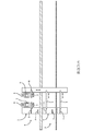
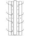
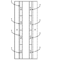
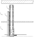
스토커(STK)는 표준화된 컨테이너, 제조 물품 또는 그 구성 요소들을 보관하기 위해 많은 산업에서 사용되는 일종의 보관 격실이다. 특수한 사양의 스토커는 특정 용례를 위한 특수한 피처(feature)를 포함할 수 있다. 예를 들어, 반도체 제조 플랜트에서 전방 개방 통합 포드(front opening unified pod)(FOUP)를 보관하기 위해 사용되는 스토커는 제어된 분위기를 유지시키기 위한 인클로저(enclosure) 및 자동화된 물류 처리 시스템(automated material handling system)(AMHS)과 상호 작용하기 위한 특수한 인터페이스를 포함할 수 있다. 일부 용례에서는, 건물의 다수의 다른 층들에서 스토커들이 필요하다. 도 1-4에 도시된 바와 같이, 표준화된 컨테이너(1)를 건물의 제2 층(4)의 스토커(2) 사이에서 제1 층(3)의 스토커(2)로 이동시키는 전통적인 방법은 표준화된 컨테이너(1)를 제2 층(4)의 스토커(2)의 선반(5)으로부터 별도의 리프팅 장치로 수평으로 이동시키는 것을 필요로 한다. 일단 표준화된 컨테이너(1)가 리프팅 장치(6) 상에 위치되면, 리프팅 장치(6)를 사용하여 제1 층(3)으로 수직으로 이동된다. 표준화된 컨테이너(1)는 그런 다음 컨베이어(7)를 통해 제1 층(3)의 스토커(2)의 선반(5)으로 수평으로 이동된다. 이 시스템은 또한 표준화된 컨테이너(1)를 스토커(2)의 상이한 영역들로 이동시키기 위한 오버헤드 이송 시스템(overhead transfer system)(8)을 포함할 수 있다. 따라서, 이 방법은 표준화된 컨테이너(1)를 이동시키는 데 다수의 단계를 필요로 하고, 다수의 장비 피스를 수반한다. 이 방법은 또한 표준화된 컨테이너(1)를 다수의 상이한 공간을 통해 이동시키는 것을 필요로 하여, 잠재적 오염의 위험성을 증가시킨다.Stockers (STKs) are a type of storage compartment used in many industries to store standardized containers, manufactured goods or components thereof. Special stockers may include special features for specific applications. For example, a stocker used to store front opening unified pods (FOUPs) in semiconductor manufacturing plants may include an enclosure and automated material handling system to maintain a controlled atmosphere. It may contain a special interface for interacting with the system (AMHS). In some applications, stockers are needed on many different floors of a building. As shown in FIGS. 1-4, the traditional method of moving the standardized container 1 from the stocker 2 of the second floor 4 of the building to the stocker 2 of the
전술한 사항을 고려하여, 화물 보관 시스템 내에서, 특히 건물의 다른 층들 상의 수직 랙들 사이에서 표준화된 컨테이너를 이동시키기 위한 시스템에 대한 개선의 필요성이 잔존한다.In view of the foregoing, there remains a need for improvements to the system for moving standardized containers within cargo storage systems, in particular between vertical racks on different floors of a building.
본 개시의 하나의 양태에 따라, 표준화된 컨테이너를 보관하기 위한 화물 보관 시스템이 제공된다. 이 화물 보관 시스템은 건물의 제1 층에 위치되는 제1 스토커 및 건물의 제2 층에 위치되는 제2 스토커를 포함한다. 제1 및 제2 스토커는 각각 표준화된 컨테이너를 지지하기 위한 적어도 하나의 화물 지지대를 포함한다. 층바닥이 제1 스토커와 제2 스토커 사이에 위치된다. 층바닥은 표준화된 컨테이너가 제1 스토커와 제2 스토커 사이에서 이동되는 것을 가능하게 해주기 위해, 제1 스토커와 제2 스토커 사이에, 제1 스토커와 제2 스토커를 직접적으로 연결시켜주는 관문(portal)를 한정한다. 관문은 제1 스토커 내의 화물 지지대들 중의 적어도 하나 및 제2 스토커 내의 화물 지지대들 중의 적어도 하나와 정렬된 상태로 위치된다. 수직 이송 장치가 제1 스토커 내의 화물 지지대들 중의 적어도 하나 및 제2 스토커 내의 화물 지지대들 중의 적어도 하나와 정렬된 상태로 위치되고, 제1 스토커와 제2 스토커 사이의 관문을 통해 표준화된 컨테이너를 이동시키도록 구성된다.According to one aspect of the present disclosure, a cargo storage system for storing standardized containers is provided. The cargo storage system includes a first stocker located on the first floor of the building and a second stocker located on the second floor of the building. The first and second stockers each comprise at least one cargo support for supporting a standardized container. The floor is located between the first stocker and the second stocker. The floor is a portal that connects the first stocker and the second stocker directly between the first stocker and the second stocker to enable the standardized container to be moved between the first stocker and the second stocker. ). The gateway is located in alignment with at least one of the cargo supports in the first stocker and at least one of the cargo supports in the second stocker. The vertical transport device is positioned in alignment with at least one of the cargo supports in the first stocker and at least one of the cargo supports in the second stocker, and moves the standardized container through the gateway between the first stocker and the second stocker. Is configured to.
본 개시의 다른 양태에 따라, 화물 보관 시스템 내에서 표준화된 컨테이너를 건물의 제1 층에 위치하여 제1 화물 지지대를 포함하는 제1 스토커와 제1 스토커 바로 위의 건물의 제2 층에 위치하여 제2 화물 지지대를 포함하는 제2 스토커 사이에서 직접적으로 이동시키기 위한 방법이 제공된다. 층바닥이 제1 스토커와 제2 스토커 사이에 위치된다. 관문이 층바닥에 의해 제1 스토커와 제2 스토커 사이에 제1 스토커의 제1 화물 지지대 및 제2 스토커의 제2 화물 지지대와 정렬된 상태로 한정된다. 이 방법은 제1 스토커 내의 화물 지지대 상에 표준화된 컨테이너를 배치시키는 단계, 표준화된 컨테이너를 수직 이송 장치와 결합시키는 단계, 수직 이송 장치로 표준화된 컨테이너를 관문을 통해 제1 스토커로부터 제2 스토커로 이동시키는 단계, 표준화된 컨테이너를 제2 스토커 내의 제2 화물 지지대 상에 위치시키는 단계, 및 수직 이송 장치로부터 표준화된 컨테이너를 결합해제시키는 단계를 포함한다.According to another aspect of the present disclosure, a standardized container within a cargo storage system is located on a first floor of a building, on a first stocker comprising a first cargo support and on a second floor of a building directly above the first stocker. A method is provided for moving directly between second stockers comprising a second cargo support. The floor is located between the first stocker and the second stocker. The gateway is defined by the floor floor in alignment with the first cargo support of the first stocker and the second cargo support of the second stocker between the first stocker and the second stocker. The method includes placing a standardized container on a cargo support in a first stocker, combining the standardized container with a vertical transport device, and connecting the standardized container with a vertical transport device from the first stocker to the second stocker via the gateway. Moving, positioning the standardized container on the second cargo support in the second stocker, and disengaging the standardized container from the vertical transport device.
따라서, 본 발명의 수직 이송 장치는, 다른 운송 장치에 의한 이송을 필요로 하지 않고 수직 이송 장치에 의해 관문을 통해 스토커들 사이에서 컨테이너를 직접적으로 이송시키기 때문에, 종래 기술의 시스템보다 신속하게 표준화된 컨테이너를 이송시킬 수 있다. 또한, 본 발명은 표준화된 컨테이너가 다수의 상이한 공간(예를 들어 컨베이어 또는 오버헤드 이송 장치 상의)을 통해 이동될 필요없이, 표준화된 컨테이너가 건물의 다른 층들 상의 수직 랙들 사이에서 직접적으로 이동되는 것을 가능하게 해주기 때문에, 잠재적 오염과 관련된 위험성이 최소화된다. 또한, 본 발명은 표준화된 컨테이너가 종래 기술의 방법보다 적은 다른 운송 장치들 사이에서의 이송으로 이동되는 것을 가능하게 해줌으로써, 각각의 이송으로 인해 초래될 수 있는 표준화된 컨테이너의 내용물에 대한 손상의 위험성을 최소화한다. Accordingly, the vertical conveying device of the present invention is standardized more quickly than the prior art system because the vertical conveying device transfers the container directly between the stockers through the gate by the vertical conveying device without requiring the conveying by another conveying device. The container can be transported. In addition, the present invention allows the standardized container to be moved directly between vertical racks on different floors of a building, without the need for the standardized container to be moved through a number of different spaces (eg on a conveyor or overhead conveying device). By making it possible, the risks associated with potential contamination are minimized. In addition, the present invention allows the standardized container to be moved in transfers between fewer different transportation devices than in the prior art methods, thereby avoiding damage to the contents of the standardized container that may be caused by each transfer. Minimize risk.
본 발명의 다른 장점들은 여기에 간단히 설명되는 첨부 도면과 관련하여 고려될 때 다음의 상세한 설명을 참조하여 더 쉽게 그리고 더 잘 이해될 수 있을 것이다.
도 1은 종래 기술의 화물 보관 시스템을 포함하는 제조 설비의 측단면도이다.
도 2는 도 1의 제조 설비의 상부 클린룸 층의 레이아웃 평면도이다.
도 3은 도 1의 제조 설비의 중간 서브팹/유틸리티 층(subfab/utility story)의 레이아웃 평면도이다.
도 4는 도 1의 제조 설비의 중간 서브팹/유틸리티 층의 스토커의 측단면도를 도시한 설계 도면이다.
도 5는 본 개시의 하나의 양태에 따른 수직 이송 장치의 제1 실시예를 포함하는 제조 설비의 개략적 측단면도이다.
도 6a는 본 개시의 하나의 양태에 따른 제1 설정에서의 분할형 선반 플레이트의 평면도이다.
도 6b는 본 개시의 하나의 양태에 따른 제2 설정에서의 도 6a의 분할 선반 플레이트의 평면도이다.
도 7은 본 개시의 하나의 양태에 따른 수직 이송 장치의 제2 실시예를 포함하는 제조 설비의 개략적 측단면도이다.
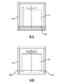
도 8a는 본 개시의 하나의 양태에 따른 표준화된 컨테이너를 둘러싸는 캡 프레임을 포함하는 화물 지지대의 측면도이다.
도 8b는 도 8a의 표준화된 컨테이너를 둘러싸는 캡 프레임을 포함하는 화물 지지대의 정면도이다.
도 9는 화물 보관 시스템 내에서 표준화된 컨테이너를 이동시키는 방법의 플로우차트이다.
도 10은 본 개시의 하나의 양태에 따른 도 9의 방법의 하위 단계를 포함하는 플로우차트이다.
도 11은 본 개시의 다른 양태에 따른 도 9의 방법의 하위 단계를 포함하는 플로우차트이다.
도 12는 본 개시의 다른 양태에 따른 도 9의 방법의 하위 단계를 포함하는 플로우차트이다. Other advantages of the present invention may be more readily and better understood with reference to the following detailed description when considered in connection with the accompanying drawings, which are briefly described herein.
1 is a side cross-sectional view of a manufacturing facility including a prior art cargo storage system.
FIG. 2 is a layout plan view of the upper clean room layer of the manufacturing facility of FIG. 1.
3 is a layout plan view of an intermediate subfab / utility story of the manufacturing facility of FIG. 1.
4 is a design diagram showing a side cross-sectional view of the stocker of the intermediate subfab / utility layer of the manufacturing facility of FIG. 1.
5 is a schematic side cross-sectional view of a manufacturing facility including a first embodiment of a vertical conveying apparatus according to one aspect of the present disclosure.
6A is a top view of a split shelf plate in a first setting in accordance with one aspect of the present disclosure.
6B is a top view of the split shelf plate of FIG. 6A in a second configuration, in accordance with one aspect of the present disclosure.
7 is a schematic side cross-sectional view of a manufacturing facility incorporating a second embodiment of a vertical transfer device in accordance with one aspect of the present disclosure.
8A is a side view of a cargo support including a cap frame surrounding a standardized container according to one aspect of the present disclosure.
FIG. 8B is a front view of the cargo support including a cap frame surrounding the standardized container of FIG. 8A.
9 is a flowchart of a method of moving a standardized container within a cargo storage system.
10 is a flowchart that includes substeps of the method of FIG. 9 in accordance with an aspect of the present disclosure.
FIG. 11 is a flowchart including substeps of the method of FIG. 9 in accordance with another aspect of the present disclosure.
12 is a flowchart that includes substeps of the method of FIG. 9 in accordance with another aspect of the present disclosure.
유사한 참조 번호가 여러 도면에 걸쳐 대응하는 부분을 지시하는 도면을 참조하면, 표준화된 컨테이너를 보관하기 위한 화물 보관 시스템(20, 120)이 제공된다. 도 5-8b에 가장 잘 도시된 바와 같이, 표준화된 컨테이너(22)는 반도체 웨이퍼를 보관 및 수송하기 위해 반도체 제조 설비에서 일반적으로 사용되는 바와 같은 전방 개방 통합 포드(front opening unified pod)(FOUP)(22)일 수 있다. 다른 컨테이너가 이용될 수도 있음을 이해해야 한다. 도시된 바와 같이, 시스템(20, 120)은 서로 상하로 수직으로 적층된 상부 룸(24), 중간 룸(26) 및 하부 룸(28)을 포함할 수 있다. 각각의 룸(24, 26, 28)은 지상 높이, 그 위 또는 그 아래의 임의의 물리적 높이에 위치할 수 있으며, 임의의 수의 룸이 제공될 수 있다. 또한, 룸은 보조 제작 룸, 유틸리티 룸 및 반도체 조립 작업을 위한 클린룸을 포함하여(이에 한정되지 않음) 다양한 목적으로 사용될 수 있다. 제1 다공성 플레이트(30) 또는 층바닥(floor)은 상부 및 중간 룸(24, 26)을 분할하고, 제2 다공성 플레이트(32) 또는 층바닥은 중간 및 하부 룸(26, 28)을 분할한다. 최하부 층바닥(34)이 하부 룸(28)에 제공되고, 천장(36)이 상부 룸(24)에 제공된다. 다공성 플레이트(30, 32), 층바닥(34) 및 천장(36)은 하방 유동 시스템에 의해 룸이 청정하게 유지되는 것을 가능하게 해주며, 청정 공기가 천장(36)을 통해 공급되어 제1 및 제2 다공성 플레이트(30, 32)를 통해 하방 유동하고 최종적으로 층바닥(34)을 통해 유동하여 제어된 분위기를 제공한다. 다른 유형의 층바닥/플레이트가 이용될 수도 있음을 이해해야 한다.Referring to the drawings, wherein like reference numerals designate corresponding parts throughout the several views, a
각각의 룸(24, 26, 28)은 스토커(stocker)(STK)(38, 40, 42)를 포함한다. 보다 구체적으로, 상부 룸(24)은 제1 스토커(38)를 포함하고, 중간 룸(26)은 제2 스토커(40)를 포함하며, 하부 룸(28)은 제3 스토커(42)를 포함한다. 각각의 스토커(38, 40, 42)는 전방 개방 통합 포드(FOUP)(22)와 같은 하나 이상의 표준화된 컨테이너(22)가 수용되는 영역이다. 스토커(38, 40, 42)는 각각 제어된 분위기를 유지시키기 위한 인클로저(enclosure) 및 자동화된 물류 처리 시스템(automated material handling system)(AMHS)과 상호 작용하기 위한 특수한 인터페이스를 포함할 수 있다. 추가적으로/대안적으로, 스토커(38, 40, 42)가 위치된 전체 룸이 상술한 바와 같이 제어된 분위기일 수 있다. 각각의 스토커(38, 40, 42)는 복수의 화물 지지대(44, 144)를 포함하고, 화물 지지대(44, 144)의 각각은 표준화된 컨테이너(22) 중의 적어도 하나를 유지시키도록 구성된다. 화물 지지대(44, 144)는 예를 들어 하나 이상의 표준화된 컨테이너(22)를 유지시키기 위한 선반(44, 144), 격실, 랙, 후크, 클램프, 또는 다른 구조나 기구를 포함할 수 있다. 예시적인 실시예에서, 화물 지지대(44, 144)는 선반(44, 144)이다. 스토커(38, 40, 42)의 각각은 또한 스토커(38, 40, 42) 내의 상이한 화물 지지대(44, 144) 사이에서 컨테이너를 이동시키도록 되어 있는 크레인(46)을 포함한다. 각각의 크레인(46)은 스토커(38, 40, 42) 내에서 컨테이너(22)를 이동시키기 위한 해당 풀리, 케이블 및/또는 다른 기구를 포함하는 암 어셈블리(48)(개략적으로 도시됨)를 포함할 수 있다.Each
제1 관문(portal)(50)이 상부 룸(24) 내의 제1 스토커(38)와 중간 룸(26) 내의 제2 스토커(40)를 연결시킨다. 제2 관문(51)이 중간 룸(26)의 제2 스토커(40)와 하부 룸(28)의 제3 스토커(42)를 연결시킨다. 제1 관문(50)은 제1 및 제2 스토커(38, 40) 사이의 직접적인 통로를 제공하고, 제2 관문(51)은 제2 및 제3 스토커(40, 42) 사이의 직접적인 통로를 제공한다. 제1 및 제2 관문(50, 51)은 제1 및 제2 다공성 플레이트(30, 32) 내의 개구 형태를 취한다. 관문(50, 51)은 표준화된 컨테이너(22)가 통과할 수 있도록 크기가 결정된다. 건물의 상부, 중간 및 하부 룸(24, 26, 28)은 도 5 및 7에 도시된 바와 같이 서로 바로 인접할 수 있다. 대안적으로, 상부, 중간 및 하부 룸(24, 26, 28)은 하나 이상의 중간 층 또는 캣워크(catwalk) 또는 플리넘(plenum)과 같은 다른 공간에 의해 이격될 수 있다. 이 경우, 관문(50, 51)은 상부, 중간 및 하부 룸(24, 26, 28)의 스토커(38, 40, 42) 사이에서 수직으로 연장되는 엘리베이터 샤프트(elevator shaft)와 유사한 하나 이상의 튜브 또는 다른 연장 통로의 형태를 취할 수 있다.A
스토커(38, 40, 42) 사이에서 관문(50)을 통해 표준화된 컨테이너를 이송시키기 위해 하나 이상의 수직 이송 장치(52, 152)가 제공된다. 수직 이송 장치(52, 152)는 선반(44, 144) 및 관문(50)과 수직 정렬된 상태로 제공되며, 표준화된 컨테이너(22)가 스토커(38, 40, 42) 사이에서 선형적으로 이동할 수 있도록 선반(44, 144)과의 수직 정렬을 유지한 채로 선형적으로 이동 가능하다.One or more vertical conveying
하나의 양태에 따라, 하나 이상의 화물 지지대(44, 144)는 표준화된 컨테이너(22)를 유지시키기 위한 제1 설정과 표준화된 컨테이너(22)가 수직 이송 장치(52, 152)에 의해 수직으로 통과하는 것을 가능하게 해주는 제2 설정 사이에서 가동적일 수 있다. 예를 들어, 도 5-6b에 도시된 시스템의 실시예에 따르면, 화물 지지대(44)는 서로에 대해 대체로 평행하고, 각각 지지 벽(56)으로부터 전방 방향으로 뻗어 있으며, 각각 전방 방향에 수직으로 측방향 바깥쪽으로 이동하도록 구성된 2개의 레그(leg)(54)를 포함하는 분할형 선반 플레이트(partitioned shelf plate)(44)일 수 있다. 이 분할형 선반 플레이트(44)는 표준화된 컨테이너(22)를 그 위에 유지시키기 위해 레그(54)가 서로 근접한 도 6a에 도시된 제1 설정과 표준화된 컨테이너(22)가 수직으로 통과하는 것을 가능하게 해주기 위해 레그(54)가 서로 이격된 도 6b에 도시된 제2 설정 사이에서 가동될 수 있다. 선형 운동(linear motion)(LM) 블록(58)이 각각의 레그(54)에 부착될 수 있고, 각각의 레그(40)가 제1 설정과 제2 설정 사이에서 측방향으로 이동되는 것을 가능하게 해주기 위해 지지 벽(56)을 따라 배치된 선형 모션 레일(60)을 따라 이동 가능하다.According to one aspect, the at least one
도 5에 도시된 바와 같이, 수직 이송 장치(52)는 스토커(38, 40, 42) 내에 배치되는 하나 이상의 호이스트(52)를 포함할 수 있다. 호이스트(52)는 표준화된 컨테이너(22) 중 하나에 대응하는 러그(49)를 선택적으로 결합시켜 그 표준화된 컨테이너(22) 중 하나를 호이스트(48) 아래에서 수직으로 수직 랙(26 30) 사이에서 이동시키기 위한 파지 기구(62)을 포함할 수 있다. 호이스트(48)는 종래 기술의 클린웨이 오버헤드 수송 차량(cleanway overhead transport vehicle)(CLW)에 사용된 유형과 유사할 수 있다. 도시된 바와 같이, 호이스트(48)는 호이스트(52)의 이동을 제공하기 위해 크레인(46)에 연결될 수 있으며, 또는 호이스트(48)는 별도의 작동 기구에 연결될 수도 있다.As shown in FIG. 5, the
도 7-8b에 도시된 시스템(120)의 실시예에 따르면, 화물 지지대(144) 중의 적어도 하나는 표준화된 컨테이너(22)를 둘러싸는 캡 프레임(cab frame)(64)을 포함할 수 있고, 화물 지지대(144)는 표준화된 컨테이너(22)를 운송하기 위해 스토커(38, 40, 42) 사이에서 이동 가능할 수 있다. 이러한 방식으로, 화물 지지대(144)는 표준화된 컨테이너(22)를 스토커(38, 40, 42) 사이에서 수직으로 운송하기 위한 엘리베이터 카(elevator car)와 유사하게 기능할 수 있다.According to the embodiment of the
도 8에 도시된 양태에 따르면, 수직 이송 장치(152)는 하나 이상의 화물 지지대(144)를 그 위에 배치된 대응하는 표준화된 컨테이너(22)와 함께 스토커(38, 4042) 사이에서 이동시키기 위한 선반 플레이트(152) 또는 레일을 포함할 수 있다. 선반 플레이트(152)는 예를 들어 2개 이상의 화물 지지대(144)의 이동을 함께 제공할 수 있다. 하나의 양태에 따라, 하나 이상의 화물 지지대(144)는 선반 플레이트(152)에 대해 수직으로 이동하도록 선반 플레이트(152)에 이동 가능하게 연결될 수 있다. 이러한 방식으로, 이동 가능한 선반 플레이트(152) 중 선택된 것은 스토커(38, 40, 42) 사이에서 이동될 수 있는 반면, 다른 것들은 정지 상태로 남을 수 있다. 대안적으로, 선반 플레이트(152)는 스토커(38, 40, 42)의 나머지 부분에 대해 이동 가능하도록 구성될 수 있고, 화물 지지대(144)는 선반 플레이트(152)에 고정되어 그와 함께 이동할 수 있다.According to the aspect shown in FIG. 8, a
도 9를 참조하면, 화물 보관 시스템(20, 120) 내에서 표준화된 컨테이너(22)를 건물의 제1 층(24)에 위치하여 제1 화물 지지대(44, 144)를 포함하는 제1 스토커(38)와 제1 스토커(38) 바로 위의 건물의 제2 층(26)에 위치하여 제2 화물 지지대(44, 144)를 포함하는 제2 스토커(40) 사이에서 직접적으로 이동시키기 위한 방법(100)이 제공되며, 층바닥 및/또는 플레이트(30)가 제1 및 제2 스토커(38, 40) 사이에 위치되고, 관문(50)이 층바닥(30)에 의해 제1 및 제2 스토커(38, 40) 사이에 제1 스토커(38) 내의 제1 화물 지지대(44, 144) 및 제2 스토커(40) 내의 제2 화물 지지대(44, 144)와 정렬된 상태로 한정된다. 이 방법(100)은 제1 스토커(38) 내의 화물 지지대(44, 144) 상에 표준화된 컨테이너를 배치시키는 단계(102)를 포함한다. 이 방법은 또한 표준화된 컨테이너를 수직 이송 장치(52, 152)와 결합시키는 단계(104)를 포함한다. 이 방법은 또한 수직 이송 장치(52, 152)로 표준화된 컨테이너(22)를 관문(50)을 통해 제1 스토커(38)로부터 제2 스토커(40)로 이동시키는 단계(106)를 포함한다. 이 방법은 또한 표준화된 컨테이너(22)를 제2 스토커(40) 내의 제2 화물 지지대(44, 144) 상에 위치시키는 단계(108)를 포함한다.With reference to FIG. 9, a first stocker having a
도 5에 도시되고, 도 10의 플로우차트에 도시된 실시예에 따르면, 표준화된 컨테이너를 수직 이송 장치(20)와 결합시키는 단계(104)는 호이스트(52)에 부착된 대응하는 파지 기구(62)를 이용하여 표준화된 컨테이너(22) 상에 러그(49)를 직접적으로 결합시키는 하위 단계(110)를 포함할 수 있다.According to the embodiment shown in FIG. 5 and shown in the flowchart of FIG. 10, the
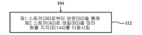
도 7에 도시되고, 도 11의 플로우차트에 도시된 시스템(120)의 실시예에 따르면, 표준화된 컨테이너를 수직 이송 장치(20)와 결합시키는 단계(104)는 제1 스토커(38)로부터 관문(50)을 통해 제2 스토커(40)로 레일(60)을 따라 화물 지지대(144)를 이동시키는 하위 단계(112)를 포함할 수 있다.According to an embodiment of the
도 12의 플로우차트에 따르면, 표준화된 컨테이너를 수직 이송 장치(20)와 결합시키는 단계(104)는 표준화된 컨테이너(22)를 유지시키기 위한 제1 설정과 표준화된 컨테이너(22)가 수직으로 통과하는 것을 가능하게 해주는 제2 설정 사이에서 하나 이상의 화물 지지대(44)를 가동시키는 하위 단계(114)를 포함할 수 있다. 구체적으로, 도 6a 및 6b에 도시된 바와 같이, 이 방법은 화물 지지대(44)의 2개의 레그(54)를 측방향 바깥쪽으로 이동시키는 단계를 포함할 수 있다.According to the flowchart of FIG. 12, the
명백히, 본 발명의 많은 수정 및 변형이 상기 교시에 비추어 가능하며, 첨부된 청구 범위의 범위 내에 있지만 구체적으로 설명된 것과 다른 방식으로 실시될 수 있다. 이러한 전제의 사항들은 신슈의 본 발명이 응용성을 발휘하는 임의의 조합을 포괄하도록 해석되어야 한다. 장치 청구항에서의 "상기"라는 단어의 사용은 청구항의 범위에 포함되는 것으로 간주되는 명백한 사항인 선행 사항을 지칭하는 반면, 단어 "그"는 청구항의 범위에 포함되지 않는 것으로 간주된다.Apparently, many modifications and variations of the present invention are possible in light of the above teachings and may be practiced otherwise than as specifically described, although within the scope of the appended claims. These prerequisites should be construed to cover any combination in which the present invention of Shinshu exhibits applicability. The use of the word "above" in a device claim refers to the foregoing, which is an obvious matter deemed to be included in the scope of the claims, while the word "he" is not considered to be within the scope of the claims.
Claims (15)
건물의 제1 층에 위치되는 제1 스토커 및 건물의 제2 층에 위치되는 제2 스토커로서, 각각이 표준화된 컨테이너를 지지하기 위한 적어도 하나의 화물 지지대를 포함하는 바의 제1 스토커 및 제2 스토커;
상기 제1 스토커와 상기 제2 스토커 사이에 위치되는 층바닥으로서, 상기 층바닥은 표준화된 컨테이너가 상기 제1 스토커와 상기 제2 스토커 사이에서 이동되는 것을 가능하게 해주기 위해, 상기 제1 스토커와 상기 제2 스토커 사이에, 상기 제1 스토커와 상기 제2 스토커를 직접적으로 연결시켜주는 관문을 한정하고, 상기 관문은 상기 제1 스토커 내의 상기 화물 지지대들 중의 적어도 하나 및 상기 제2 스토커 내의 상기 화물 지지대들 중의 적어도 하나와 정렬된 상태로 한정되는 바의 층바닥; 및
상기 제1 스토커 내의 상기 화물 지지대들 중의 적어도 하나 및 상기 제2 스토커 내의 상기 화물 지지대들 중의 적어도 하나와 정렬된 상태로 위치되고, 상기 제1 스토커와 상기 제2 스토커 사이의 상기 관문을 통해 표준화된 컨테이너를 이동시키도록 구성되는 수직 이송 장치를 포함하는 것을 특징으로 하는 화물 보관 시스템.In a cargo storage system for storing standardized containers,
A first stocker located on a first floor of a building and a second stocker located on a second floor of a building, wherein the first stocker and second bar of the bar each include at least one cargo support for supporting a standardized container stalker;
A layered floor positioned between the first stocker and the second stocker, the layered floor allowing the standardized container to be moved between the first stocker and the second stocker, the first stocker and the second stocker Between a second stocker, define a gate that directly connects the first stocker and the second stocker, the gate at least one of the cargo supports in the first stocker and the cargo support in the second stocker A floor of the bar defined in alignment with at least one of the two; And
Positioned in alignment with at least one of the cargo supports in the first stocker and at least one of the cargo supports in the second stocker, and standardized through the gateway between the first stocker and the second stocker A cargo storage system comprising a vertical conveying device configured to move a container.
제1 스토커 내의 제1 화물 지지대 상에 표준화된 컨테이너를 배치시키는 단계;
표준화된 컨테이너를 수직 이송 장치와 결합시키는 단계;
수직 이송 장치로 표준화된 컨테이너를 관문을 통해 제1 스토커로부터 제2 스토커로 이동시키고, 표준화된 컨테이너를 제2 스토커 내의 제2 화물 지지대 상에 위치시키는 단계; 및
수직 이송 장치로부터 표준화된 컨테이너를 결합해제시키는 단계를 포함하는 것을 특징으로 하는 방법.Within a cargo storage system, a standardized container is placed on a first floor of a building to include a first stocker comprising a first cargo support and a second cargo support located on a second floor of a building immediately above the first stocker. A method for moving directly between two stockers, wherein the floor is located between the first stocker and the second stocker, and the gateway is located between the first stocker and the second stocker by the floor, the first cargo support in the first stocker. And wherein the method is limited to being aligned with a second cargo support in the second stocker, the method comprising:
Placing a standardized container on a first cargo support in the first stocker;
Combining the standardized container with a vertical conveying device;
Moving the standardized container from the first stocker to the second stocker via a gateway with a vertical transfer device and placing the standardized container on a second cargo support in the second stocker; And
Decoupling the standardized container from the vertical conveying device.
11. The method of claim 10, wherein the first stocker comprises a plurality of first cargo supports positioned in vertical alignment with each other, and the second stocker includes a plurality of second cargo supports positioned in vertical alignment with each other. Cargo storage system.
Applications Claiming Priority (3)
| Application Number | Priority Date | Filing Date | Title |
|---|---|---|---|
| US201762482395P | 2017-04-06 | 2017-04-06 | |
| US62/482,395 | 2017-04-06 | ||
| PCT/US2018/025688 WO2018187208A1 (en) | 2017-04-06 | 2018-04-02 | Storage system including a vertical transfer device |
Publications (2)
| Publication Number | Publication Date |
|---|---|
| KR20190134656A true KR20190134656A (en) | 2019-12-04 |
| KR102633352B1 KR102633352B1 (en) | 2024-02-06 |
Family
ID=63712751
Family Applications (1)
| Application Number | Title | Priority Date | Filing Date |
|---|---|---|---|
| KR1020197029712A KR102633352B1 (en) | 2017-04-06 | 2018-04-02 | Storage system with vertical transport device |
Country Status (6)
| Country | Link |
|---|---|
| US (1) | US11235926B2 (en) |
| JP (1) | JP6861296B2 (en) |
| KR (1) | KR102633352B1 (en) |
| CN (1) | CN110475730B (en) |
| TW (1) | TWI746835B (en) |
| WO (1) | WO2018187208A1 (en) |
Families Citing this family (1)
| Publication number | Priority date | Publication date | Assignee | Title |
|---|---|---|---|---|
| SG11202106551XA (en) * | 2018-12-26 | 2021-07-29 | Murata Machinery Ltd | Storage system |
Citations (4)
| Publication number | Priority date | Publication date | Assignee | Title |
|---|---|---|---|---|
| KR20030019876A (en) * | 2001-08-31 | 2003-03-07 | 가부시키가이샤 다이후쿠 | Load storage apparatus |
| KR20130110056A (en) * | 2012-03-27 | 2013-10-08 | 가부시키가이샤 다이후쿠 | Article storage facility and article transport facility |
| KR20160008462A (en) * | 2014-07-14 | 2016-01-22 | 가부시키가이샤 다이후쿠 | Inter-floor transport facility |
| KR20160092488A (en) * | 2015-01-27 | 2016-08-04 | 가부시키가이샤 다이후쿠 | Article transport facility |
Family Cites Families (13)
| Publication number | Priority date | Publication date | Assignee | Title |
|---|---|---|---|---|
| CN1004919B (en) * | 1985-07-02 | 1989-08-02 | 贝洛克·阿兰 | Equipment and method for placing goods on goods-sales shelves |
| JPS63196050A (en) * | 1987-02-10 | 1988-08-15 | Hitachi Electronics Eng Co Ltd | Flexible set mechanism of leadframe magazine |
| JPH06115615A (en) * | 1992-10-01 | 1994-04-26 | Murata Mach Ltd | Storage |
| JP4470576B2 (en) * | 2003-05-20 | 2010-06-02 | ムラテックオートメーション株式会社 | Transport system |
| EP1801869A4 (en) * | 2004-09-24 | 2010-12-08 | Hirata Spinning | Container carrying equipment |
| US9834378B2 (en) | 2006-12-22 | 2017-12-05 | Brooks Automation, Inc. | Loader and buffer for reduced lot size |
| US20090081010A1 (en) * | 2007-09-20 | 2009-03-26 | Leelananda Jayasuriya | Inclined Conveyance for Multi-storied Automotive Parking |
| JP5228504B2 (en) * | 2008-01-24 | 2013-07-03 | 村田機械株式会社 | Storage and entry / exit methods |
| JP5500371B2 (en) * | 2010-07-23 | 2014-05-21 | 株式会社ダイフク | Goods transport equipment |
| JP5776947B2 (en) * | 2013-06-12 | 2015-09-09 | 株式会社ダイフク | Inert gas injector for storage shelves |
| JP5979089B2 (en) * | 2013-06-26 | 2016-08-24 | 株式会社ダイフク | Storage facilities |
| JP6304045B2 (en) | 2015-01-06 | 2018-04-04 | 株式会社ダイフク | Goods storage facility |
| JP6443264B2 (en) | 2015-08-12 | 2018-12-26 | 株式会社ダイフク | Goods storage equipment |
-
2018
- 2018-04-02 KR KR1020197029712A patent/KR102633352B1/en active IP Right Grant
- 2018-04-02 JP JP2019555146A patent/JP6861296B2/en active Active
- 2018-04-02 CN CN201880022807.1A patent/CN110475730B/en active Active
- 2018-04-02 US US16/603,052 patent/US11235926B2/en active Active
- 2018-04-02 WO PCT/US2018/025688 patent/WO2018187208A1/en active Application Filing
- 2018-04-09 TW TW107112094A patent/TWI746835B/en active
Patent Citations (4)
| Publication number | Priority date | Publication date | Assignee | Title |
|---|---|---|---|---|
| KR20030019876A (en) * | 2001-08-31 | 2003-03-07 | 가부시키가이샤 다이후쿠 | Load storage apparatus |
| KR20130110056A (en) * | 2012-03-27 | 2013-10-08 | 가부시키가이샤 다이후쿠 | Article storage facility and article transport facility |
| KR20160008462A (en) * | 2014-07-14 | 2016-01-22 | 가부시키가이샤 다이후쿠 | Inter-floor transport facility |
| KR20160092488A (en) * | 2015-01-27 | 2016-08-04 | 가부시키가이샤 다이후쿠 | Article transport facility |
Also Published As
| Publication number | Publication date |
|---|---|
| JP6861296B2 (en) | 2021-04-21 |
| TW201900523A (en) | 2019-01-01 |
| CN110475730B (en) | 2022-03-15 |
| US11235926B2 (en) | 2022-02-01 |
| CN110475730A (en) | 2019-11-19 |
| US20210078800A1 (en) | 2021-03-18 |
| JP2020512964A (en) | 2020-04-30 |
| WO2018187208A1 (en) | 2018-10-11 |
| TWI746835B (en) | 2021-11-21 |
| KR102633352B1 (en) | 2024-02-06 |
Similar Documents
| Publication | Publication Date | Title |
|---|---|---|
| US9548230B2 (en) | Temporary storage device, transport system, and temporary storage method | |
| US7780392B2 (en) | Horizontal array stocker | |
| KR100868247B1 (en) | Overhead traveling vehicle system | |
| KR102276842B1 (en) | Inter―floor transport facility | |
| EP3200221B1 (en) | Purging device and purging method | |
| KR20140010984A (en) | Load port apparatus, carrier system, and container conveyance method | |
| KR20090026099A (en) | Storage, transporting system and storage set | |
| KR20110097599A (en) | Transporting vehicle system | |
| US20090022575A1 (en) | Article storing apparatus | |
| JP2008019017A (en) | Article storage device | |
| KR102633352B1 (en) | Storage system with vertical transport device | |
| WO2013150841A1 (en) | Conveyance system | |
| WO2017043234A1 (en) | Transport system and transport method | |
| KR102306368B1 (en) | flat storage facility | |
| US8753061B2 (en) | Transport system having multilayer tracks and controlling method thereof | |
| KR102648735B1 (en) | high density stalker | |
| KR20210054992A (en) | Substrate processing apparatus and substrate receptacle storage method | |
| JPH0318405Y2 (en) | ||
| JP2024509925A (en) | automatic storage system | |
| EP3581521B1 (en) | Stocker | |
| JP2009062154A (en) | Storage and carrying system with storage | |
| KR20200101280A (en) | Article storage facility | |
| KR20040072221A (en) | Equipment and method for storing carriers | |
| JPH02270720A (en) | Conveying facility between process devices | |
| JP2009012965A (en) | Stocker device |
Legal Events
| Date | Code | Title | Description |
|---|---|---|---|
| E902 | Notification of reason for refusal | ||
| E701 | Decision to grant or registration of patent right | ||
| GRNT | Written decision to grant |