KR20190131031A - Systems and Methods for Noise Reduction in Imaging - Google Patents
Systems and Methods for Noise Reduction in Imaging Download PDFInfo
- Publication number
- KR20190131031A KR20190131031A KR1020197027630A KR20197027630A KR20190131031A KR 20190131031 A KR20190131031 A KR 20190131031A KR 1020197027630 A KR1020197027630 A KR 1020197027630A KR 20197027630 A KR20197027630 A KR 20197027630A KR 20190131031 A KR20190131031 A KR 20190131031A
- Authority
- KR
- South Korea
- Prior art keywords
- imaging
- band
- noise
- waveform
- detection
- Prior art date
Links
- 238000003384 imaging method Methods 0.000 title claims abstract description 1202
- 238000000034 method Methods 0.000 title claims abstract description 206
- 230000009467 reduction Effects 0.000 title claims description 143
- 238000001514 detection method Methods 0.000 claims abstract description 458
- 238000012512 characterization method Methods 0.000 claims description 313
- 238000012545 processing Methods 0.000 claims description 94
- 238000012937 correction Methods 0.000 claims description 80
- 238000001914 filtration Methods 0.000 claims description 68
- 230000001629 suppression Effects 0.000 claims description 44
- 238000004422 calculation algorithm Methods 0.000 claims description 41
- 238000005259 measurement Methods 0.000 claims description 40
- 230000003044 adaptive effect Effects 0.000 claims description 19
- 238000003909 pattern recognition Methods 0.000 claims description 16
- 230000026683 transduction Effects 0.000 claims description 10
- 238000010361 transduction Methods 0.000 claims description 10
- 230000035945 sensitivity Effects 0.000 claims description 7
- 230000007423 decrease Effects 0.000 claims description 5
- 238000012544 monitoring process Methods 0.000 claims description 4
- 230000008859 change Effects 0.000 claims description 3
- 230000001419 dependent effect Effects 0.000 claims description 3
- 230000001360 synchronised effect Effects 0.000 claims description 2
- 230000035807 sensation Effects 0.000 claims 2
- 238000003491 array Methods 0.000 description 60
- 239000000523 sample Substances 0.000 description 31
- 238000002604 ultrasonography Methods 0.000 description 23
- 230000006870 function Effects 0.000 description 19
- 230000002596 correlated effect Effects 0.000 description 17
- 230000000875 corresponding effect Effects 0.000 description 16
- 238000002679 ablation Methods 0.000 description 15
- 238000002595 magnetic resonance imaging Methods 0.000 description 12
- 230000002829 reductive effect Effects 0.000 description 12
- 230000008569 process Effects 0.000 description 11
- 230000000737 periodic effect Effects 0.000 description 10
- 238000003860 storage Methods 0.000 description 10
- 238000012285 ultrasound imaging Methods 0.000 description 9
- 238000013016 damping Methods 0.000 description 8
- 238000013507 mapping Methods 0.000 description 8
- 230000003595 spectral effect Effects 0.000 description 8
- 230000003287 optical effect Effects 0.000 description 7
- 238000002592 echocardiography Methods 0.000 description 6
- 230000000670 limiting effect Effects 0.000 description 6
- 230000002123 temporal effect Effects 0.000 description 6
- 238000012935 Averaging Methods 0.000 description 5
- 238000013459 approach Methods 0.000 description 5
- 230000005540 biological transmission Effects 0.000 description 5
- 230000002238 attenuated effect Effects 0.000 description 4
- 230000008901 benefit Effects 0.000 description 4
- 238000006243 chemical reaction Methods 0.000 description 4
- 238000001208 nuclear magnetic resonance pulse sequence Methods 0.000 description 4
- 230000004044 response Effects 0.000 description 4
- 238000001228 spectrum Methods 0.000 description 4
- 238000004458 analytical method Methods 0.000 description 3
- 239000004020 conductor Substances 0.000 description 3
- 238000002474 experimental method Methods 0.000 description 3
- 230000006872 improvement Effects 0.000 description 3
- 238000012886 linear function Methods 0.000 description 3
- 230000007246 mechanism Effects 0.000 description 3
- 230000036962 time dependent Effects 0.000 description 3
- 238000013519 translation Methods 0.000 description 3
- FAPWRFPIFSIZLT-UHFFFAOYSA-M Sodium chloride Chemical compound [Na+].[Cl-] FAPWRFPIFSIZLT-UHFFFAOYSA-M 0.000 description 2
- 238000004364 calculation method Methods 0.000 description 2
- 239000003990 capacitor Substances 0.000 description 2
- 238000004891 communication Methods 0.000 description 2
- 230000000694 effects Effects 0.000 description 2
- 230000007613 environmental effect Effects 0.000 description 2
- 238000011156 evaluation Methods 0.000 description 2
- 238000000605 extraction Methods 0.000 description 2
- 230000000004 hemodynamic effect Effects 0.000 description 2
- 238000001727 in vivo Methods 0.000 description 2
- 238000011503 in vivo imaging Methods 0.000 description 2
- 238000002955 isolation Methods 0.000 description 2
- 238000010801 machine learning Methods 0.000 description 2
- 238000004519 manufacturing process Methods 0.000 description 2
- 239000000463 material Substances 0.000 description 2
- 238000012986 modification Methods 0.000 description 2
- 230000004048 modification Effects 0.000 description 2
- 238000005457 optimization Methods 0.000 description 2
- 230000001902 propagating effect Effects 0.000 description 2
- 238000000926 separation method Methods 0.000 description 2
- 239000011780 sodium chloride Substances 0.000 description 2
- 239000004593 Epoxy Substances 0.000 description 1
- 244000208734 Pisonia aculeata Species 0.000 description 1
- 230000004913 activation Effects 0.000 description 1
- 230000002411 adverse Effects 0.000 description 1
- 206010003119 arrhythmia Diseases 0.000 description 1
- 230000006793 arrhythmia Effects 0.000 description 1
- 238000013528 artificial neural network Methods 0.000 description 1
- 238000005311 autocorrelation function Methods 0.000 description 1
- 230000000747 cardiac effect Effects 0.000 description 1
- 230000015556 catabolic process Effects 0.000 description 1
- 238000007635 classification algorithm Methods 0.000 description 1
- 230000001143 conditioned effect Effects 0.000 description 1
- 230000009849 deactivation Effects 0.000 description 1
- 238000006731 degradation reaction Methods 0.000 description 1
- 238000002059 diagnostic imaging Methods 0.000 description 1
- 230000005672 electromagnetic field Effects 0.000 description 1
- 230000005284 excitation Effects 0.000 description 1
- 239000000284 extract Substances 0.000 description 1
- 230000005669 field effect Effects 0.000 description 1
- 230000006698 induction Effects 0.000 description 1
- 238000001802 infusion Methods 0.000 description 1
- 238000002608 intravascular ultrasound Methods 0.000 description 1
- 238000003064 k means clustering Methods 0.000 description 1
- 230000004807 localization Effects 0.000 description 1
- 239000011159 matrix material Substances 0.000 description 1
- 230000002093 peripheral effect Effects 0.000 description 1
- 230000010287 polarization Effects 0.000 description 1
- 238000012805 post-processing Methods 0.000 description 1
- 238000003825 pressing Methods 0.000 description 1
- 238000003672 processing method Methods 0.000 description 1
- 230000005855 radiation Effects 0.000 description 1
- 238000007674 radiofrequency ablation Methods 0.000 description 1
- 230000000241 respiratory effect Effects 0.000 description 1
- 230000002441 reversible effect Effects 0.000 description 1
- 238000005070 sampling Methods 0.000 description 1
- 238000010183 spectrum analysis Methods 0.000 description 1
- 239000000758 substrate Substances 0.000 description 1
- 238000012706 support-vector machine Methods 0.000 description 1
- 238000012546 transfer Methods 0.000 description 1
- 230000009466 transformation Effects 0.000 description 1
- 230000001960 triggered effect Effects 0.000 description 1
- 238000012800 visualization Methods 0.000 description 1
Images


Classifications
-
- G—PHYSICS
- G06—COMPUTING; CALCULATING OR COUNTING
- G06T—IMAGE DATA PROCESSING OR GENERATION, IN GENERAL
- G06T5/00—Image enhancement or restoration
- G06T5/001—Image restoration
- G06T5/002—Denoising; Smoothing
-
- G—PHYSICS
- G01—MEASURING; TESTING
- G01S—RADIO DIRECTION-FINDING; RADIO NAVIGATION; DETERMINING DISTANCE OR VELOCITY BY USE OF RADIO WAVES; LOCATING OR PRESENCE-DETECTING BY USE OF THE REFLECTION OR RERADIATION OF RADIO WAVES; ANALOGOUS ARRANGEMENTS USING OTHER WAVES
- G01S7/00—Details of systems according to groups G01S13/00, G01S15/00, G01S17/00
- G01S7/52—Details of systems according to groups G01S13/00, G01S15/00, G01S17/00 of systems according to group G01S15/00
- G01S7/52017—Details of systems according to groups G01S13/00, G01S15/00, G01S17/00 of systems according to group G01S15/00 particularly adapted to short-range imaging
- G01S7/5205—Means for monitoring or calibrating
-
- G06T5/70—
-
- A—HUMAN NECESSITIES
- A61—MEDICAL OR VETERINARY SCIENCE; HYGIENE
- A61B—DIAGNOSIS; SURGERY; IDENTIFICATION
- A61B8/00—Diagnosis using ultrasonic, sonic or infrasonic waves
- A61B8/52—Devices using data or image processing specially adapted for diagnosis using ultrasonic, sonic or infrasonic waves
- A61B8/5207—Devices using data or image processing specially adapted for diagnosis using ultrasonic, sonic or infrasonic waves involving processing of raw data to produce diagnostic data, e.g. for generating an image
-
- A—HUMAN NECESSITIES
- A61—MEDICAL OR VETERINARY SCIENCE; HYGIENE
- A61B—DIAGNOSIS; SURGERY; IDENTIFICATION
- A61B8/00—Diagnosis using ultrasonic, sonic or infrasonic waves
- A61B8/52—Devices using data or image processing specially adapted for diagnosis using ultrasonic, sonic or infrasonic waves
- A61B8/5269—Devices using data or image processing specially adapted for diagnosis using ultrasonic, sonic or infrasonic waves involving detection or reduction of artifacts
-
- G—PHYSICS
- G01—MEASURING; TESTING
- G01R—MEASURING ELECTRIC VARIABLES; MEASURING MAGNETIC VARIABLES
- G01R33/00—Arrangements or instruments for measuring magnetic variables
- G01R33/20—Arrangements or instruments for measuring magnetic variables involving magnetic resonance
- G01R33/44—Arrangements or instruments for measuring magnetic variables involving magnetic resonance using nuclear magnetic resonance [NMR]
- G01R33/48—NMR imaging systems
- G01R33/54—Signal processing systems, e.g. using pulse sequences ; Generation or control of pulse sequences; Operator console
- G01R33/56—Image enhancement or correction, e.g. subtraction or averaging techniques, e.g. improvement of signal-to-noise ratio and resolution
- G01R33/5608—Data processing and visualization specially adapted for MR, e.g. for feature analysis and pattern recognition on the basis of measured MR data, segmentation of measured MR data, edge contour detection on the basis of measured MR data, for enhancing measured MR data in terms of signal-to-noise ratio by means of noise filtering or apodization, for enhancing measured MR data in terms of resolution by means for deblurring, windowing, zero filling, or generation of gray-scaled images, colour-coded images or images displaying vectors instead of pixels
-
- G—PHYSICS
- G01—MEASURING; TESTING
- G01S—RADIO DIRECTION-FINDING; RADIO NAVIGATION; DETERMINING DISTANCE OR VELOCITY BY USE OF RADIO WAVES; LOCATING OR PRESENCE-DETECTING BY USE OF THE REFLECTION OR RERADIATION OF RADIO WAVES; ANALOGOUS ARRANGEMENTS USING OTHER WAVES
- G01S7/00—Details of systems according to groups G01S13/00, G01S15/00, G01S17/00
- G01S7/52—Details of systems according to groups G01S13/00, G01S15/00, G01S17/00 of systems according to group G01S15/00
- G01S7/52017—Details of systems according to groups G01S13/00, G01S15/00, G01S17/00 of systems according to group G01S15/00 particularly adapted to short-range imaging
- G01S7/52077—Details of systems according to groups G01S13/00, G01S15/00, G01S17/00 of systems according to group G01S15/00 particularly adapted to short-range imaging with means for elimination of unwanted signals, e.g. noise or interference
-
- G—PHYSICS
- G06—COMPUTING; CALCULATING OR COUNTING
- G06T—IMAGE DATA PROCESSING OR GENERATION, IN GENERAL
- G06T5/00—Image enhancement or restoration
- G06T5/10—Image enhancement or restoration by non-spatial domain filtering
-
- A—HUMAN NECESSITIES
- A61—MEDICAL OR VETERINARY SCIENCE; HYGIENE
- A61B—DIAGNOSIS; SURGERY; IDENTIFICATION
- A61B5/00—Measuring for diagnostic purposes; Identification of persons
- A61B5/72—Signal processing specially adapted for physiological signals or for diagnostic purposes
- A61B5/7203—Signal processing specially adapted for physiological signals or for diagnostic purposes for noise prevention, reduction or removal
- A61B5/7217—Signal processing specially adapted for physiological signals or for diagnostic purposes for noise prevention, reduction or removal of noise originating from a therapeutic or surgical apparatus, e.g. from a pacemaker
-
- A—HUMAN NECESSITIES
- A61—MEDICAL OR VETERINARY SCIENCE; HYGIENE
- A61B—DIAGNOSIS; SURGERY; IDENTIFICATION
- A61B8/00—Diagnosis using ultrasonic, sonic or infrasonic waves
- A61B8/12—Diagnosis using ultrasonic, sonic or infrasonic waves in body cavities or body tracts, e.g. by using catheters
-
- A—HUMAN NECESSITIES
- A61—MEDICAL OR VETERINARY SCIENCE; HYGIENE
- A61B—DIAGNOSIS; SURGERY; IDENTIFICATION
- A61B8/00—Diagnosis using ultrasonic, sonic or infrasonic waves
- A61B8/46—Ultrasonic, sonic or infrasonic diagnostic devices with special arrangements for interfacing with the operator or the patient
-
- A—HUMAN NECESSITIES
- A61—MEDICAL OR VETERINARY SCIENCE; HYGIENE
- A61B—DIAGNOSIS; SURGERY; IDENTIFICATION
- A61B8/00—Diagnosis using ultrasonic, sonic or infrasonic waves
- A61B8/52—Devices using data or image processing specially adapted for diagnosis using ultrasonic, sonic or infrasonic waves
- A61B8/5269—Devices using data or image processing specially adapted for diagnosis using ultrasonic, sonic or infrasonic waves involving detection or reduction of artifacts
- A61B8/5276—Devices using data or image processing specially adapted for diagnosis using ultrasonic, sonic or infrasonic waves involving detection or reduction of artifacts due to motion
-
- G—PHYSICS
- G06—COMPUTING; CALCULATING OR COUNTING
- G06T—IMAGE DATA PROCESSING OR GENERATION, IN GENERAL
- G06T2207/00—Indexing scheme for image analysis or image enhancement
- G06T2207/10—Image acquisition modality
- G06T2207/10072—Tomographic images
- G06T2207/10088—Magnetic resonance imaging [MRI]
-
- G—PHYSICS
- G06—COMPUTING; CALCULATING OR COUNTING
- G06T—IMAGE DATA PROCESSING OR GENERATION, IN GENERAL
- G06T2207/00—Indexing scheme for image analysis or image enhancement
- G06T2207/10—Image acquisition modality
- G06T2207/10132—Ultrasound image
-
- G—PHYSICS
- G06—COMPUTING; CALCULATING OR COUNTING
- G06T—IMAGE DATA PROCESSING OR GENERATION, IN GENERAL
- G06T2207/00—Indexing scheme for image analysis or image enhancement
- G06T2207/20—Special algorithmic details
- G06T2207/20048—Transform domain processing
- G06T2207/20056—Discrete and fast Fourier transform, [DFT, FFT]
Abstract
대역내 노이즈의 검출 및/또는 추정에 기초하여 광대역 노이즈의 존재 시의 이미지들의 디노이징을 위한 시스템들 및 방법들이 제공된다. 다양한 예시적인 실시예들에 따르면, 이미징 대역 내에 있는 광대역 노이즈의 추정은 이미징 대역 밖에 있는 대역외 노이즈를 검출 또는 특성화하는 것에 의해 이루어진다. 이 추정된 대역내 노이즈는 검출된 이미징 파형을 디노이징하는 데 이용될 수 있다. 다른 예시적인 실시예들에 따르면, 이미징 대역 내의 노이즈에 민감하지만 이미징 에너지로부터 격리된 기준 수신 회로는 이미징 대역 내의 노이즈를 검출 및/또는 특성화하는 데 이용될 수 있다. 추정된 기준 노이즈는 검출된 대역내 이미징 파형을 디노이징하는 데 이용될 수 있다.Systems and methods are provided for denoising images in the presence of broadband noise based on detection and / or estimation of in-band noise. According to various exemplary embodiments, estimation of broadband noise within the imaging band is made by detecting or characterizing out-of-band noise outside the imaging band. This estimated in-band noise can be used to denoise the detected imaging waveform. According to other exemplary embodiments, reference receiving circuits that are sensitive to noise in the imaging band but isolated from the imaging energy may be used to detect and / or characterize noise in the imaging band. The estimated reference noise can be used to denoise the detected in-band imaging waveform.
Description
본 출원은, 그 전체 내용이 본 명세서에 참고로 포함되는, 2017년 2월 24일자로 출원된 발명의 명칭이 "SYSTEMS AND METHODS FOR NOISE REDUCTION IN IMAGING"인 미국 가출원 제62/463,431호에 대한 우선권을 주장한다.This application claims priority to US Provisional Application No. 62 / 463,431, entitled "SYSTEMS AND METHODS FOR NOISE REDUCTION IN IMAGING," filed February 24, 2017, the entire contents of which are incorporated herein by reference. Insist.
본 개시내용은 이미징 기술들 및 노이즈 제거를 위한 이미징 데이터의 프로세싱에 관한 것이다.The present disclosure relates to imaging techniques and processing of imaging data for noise cancellation.
초음파 및 MRI 이미징을 사용한 의료 이미징은, 전형적으로 2 MHz 내지 200MHz에 걸쳐 있는, 무선 주파수 스펙트럼에서의 저 진폭 신호들을 검출하는 것에 의존한다. 이미지 품질은 신호대 노이즈비(signal-to-noise ratio)에 의해 크게 영향을 받는다.Medical imaging using ultrasound and MRI imaging relies on detecting low amplitude signals in the radio frequency spectrum, typically spanning 2 MHz to 200 MHz. Image quality is greatly affected by the signal-to-noise ratio.
IVUS(intravascular ultrasound), ICE(intracardiac echocardiography) 및 다른 형태들의 최소 침습적 초음파(minimally invasive ultrasound)에서, 초음파 트랜스듀서는 주변 구조물들로부터의 초음파 신호들을 검출하고 음향 에너지를 전기 신호로 변환한다. 이 신호는 이어서 (동축 도체(coaxial conductor), 연선 도체(twisted pair conductor), 플렉스 회로(flex circuit) 등과 같은) 하나 이상의 전도성 채널을 따라 전송된다. (비용, 제조성(manufacturability), 안전성, 생체적합성(biocompatibility), 열 문제들, 및 전력 제공을 위한 요구사항들을 포함한) 많은 이유들로, 체내에(intracorporeally) 삽입될 수 있는 최소 침습적 이미징 프로브의 부분은 종종 신호 강도를 부스팅하기 위한 증폭기를 포함하지 않는다. 최소 침습적 초음파 트랜스듀서들에 의해 검출된 전기 신호들은 매우 작을 수 있으며(< 10mV 그리고 보다 전형적으로 < 1 mv), 초음파로 이미징될 수 있는 조직 구조(tissue structure)에 관한 정보의 상당 부분은 검출되는 전기 신호들의 다이내믹 레인지(dynamic range)의 하위 부분(lower portion)에 있는 경향이 있다. 수신된 초음파 신호의 신호 진폭은 트랜스듀서의 기계적 효율, 검출된 음향 신호들의 낮은 진폭, 트랜스듀서의 작은 크기 및 트랜스듀서로부터 신체 밖으로 전기 신호를 운반하는 도체들을 따른 감쇠에 의해 제한된다. 이것을 고려하면, 최소 침습적 초음파 이미징 시스템들에서의 신호들은 매우 약한 경향이 있다.In intravascular ultrasound (IVUS), intraracous echocardiography (ICE), and other forms of minimally invasive ultrasound, an ultrasonic transducer detects ultrasonic signals from surrounding structures and converts acoustic energy into electrical signals. This signal is then transmitted along one or more conductive channels (such as coaxial conductors, twisted pair conductors, flex circuits, etc.). Of minimally invasive imaging probes that can be inserted intracorporeally for many reasons (including cost, manufacturability, safety, biocompatibility, thermal issues, and requirements for providing power). The part often does not include an amplifier to boost the signal strength. The electrical signals detected by the minimally invasive ultrasound transducers can be very small (<10 mV and more typically <1 mv), and much of the information about tissue structures that can be imaged with ultrasound is detected. There is a tendency to be in the lower portion of the dynamic range of electrical signals. The signal amplitude of the received ultrasonic signal is limited by the mechanical efficiency of the transducer, the low amplitude of the detected acoustic signals, the small size of the transducer and the attenuation along the conductors carrying the electrical signal out of the body from the transducer. With this in mind, signals in minimally invasive ultrasound imaging systems tend to be very weak.
무선 송신기들, 전력 전자기기들, 전송 라인들, 스위칭 트랜지스터들 및 본 기술분야에 공지된 다른 것들을 포함한, 많은 소스들로부터 시스템에 노이즈가 유입될 수 있다. 전자기 간섭에 민감한 컴포넌트들의 유도를 통해 또는 전도 및 최적이 아닌 격리(suboptimal isolation)를 통해 직접적으로 노이즈가 유입될 수 있다. 노이즈 중 일부는, 스캐닝 액추에이터들, 모터 제어기들에 대한 펄스 폭 변조기들, 스위치 모드 전원들(switched mode power supplies), 클로킹 회로들 및 이미징 시스템의 전자 컴포넌트들 중 임의의 것에 있는 트랜지스터들과 같은, 이미징 시스템 자체 내의 컴포넌트들에 의해 생성될 수 있다. 게다가, 임피던스 모니터들, (Carto® 3, Carto® XP 또는 NavX™ 시스템들에서 발견되는 것들과 같은) 트래킹 시스템들, 온도 센서들, 주입 펌프들, 어블레이션 시스템들, ECG 및 혈류동태 모니터들(hemodynamic monitors)과 같은, 환자에 커플링된 또는 시술 환경(procedural environment)에 있는 다른 시스템들이 노이즈를 유입시킬 수 있다. 일부 임상 영역들(clinical areas)에서 사용되는 RFID 재고 관리 시스템들이 또한 노이즈를 유입시킬 수 있다.Noise can enter the system from many sources, including wireless transmitters, power electronics, transmission lines, switching transistors, and others known in the art. Noise can be introduced directly through the induction of components sensitive to electromagnetic interference or through conduction and suboptimal isolation. Some of the noise is such as transistors in any of the scanning actuators, pulse width modulators for motor controllers, switched mode power supplies, clocking circuits and electronic components of the imaging system, It may be generated by components within the imaging system itself. In addition, impedance monitors, tracking systems (such as those found in Carto ® 3, Carto ® XP or NavX ™ systems), temperature sensors, infusion pumps, ablation systems, ECG and hemodynamic monitors ( Other systems, such as hemodynamic monitors, coupled to the patient or in a procedural environment can introduce noise. RFID inventory management systems used in some clinical areas can also introduce noise.
몇 가지 접근법은, 최소의 RF 노이즈를 생성하는 시스템 내의 컴포넌트들의 선택, 전기적 격리, 실딩(shielding), 적절한 접지, 및 노이즈 생성 컴포넌트들을 전자기 노이즈에 취약한 컴포넌트들로부터 물리적으로 분리시키는 것을 포함한, 초음파 이미징 시스템들의 초음파 수신 회로부에 들어오는 노이즈 양을 감소시키는 것에 관한 것이다. 노이즈의 소스들이 종종 다른 이유들로 선호된 특성들을 갖거나(즉, 펄스 폭 변조 모터 제어기들은 에너지 효율적이고 양호한 응답 시간들을 가짐) 서로 물리적으로 격리하기 어렵기 때문에(즉, 이미징 프로브 또는 그와 연관된 회로부에 가깝게 근접하여 전력 전자기기들을 갖는 것이 바람직할 수 있음), 이 접근법들은 종종 구현하기가 어렵다.Some approaches include ultrasonic imaging, including the selection of components in the system that generate minimal RF noise, electrical isolation, shielding, proper grounding, and physical separation of noise generating components from components susceptible to electromagnetic noise. It is directed to reducing the amount of noise entering the ultrasonic receiving circuitry of systems. Sources of noise often have preferred characteristics for different reasons (ie, pulse width modulated motor controllers are energy efficient and have good response times) or are difficult to physically isolate from each other (ie, imaging probes or their associated It may be desirable to have power electronics in close proximity to the circuitry), these approaches are often difficult to implement.
초음파 신호 품질(따라서 초음파 이미지 품질)에 대한 노이즈의 영향을 감소시키기 위한 다른 접근법들은 필터링 및 이미지 프로세싱을 포함한다. 초음파 신호들은 전형적으로 알려진 대역폭을 가지며, 검출된 초음파 신호는 아날로그 또는 디지털 필터링 기술들(종종이 이 둘의 조합)을 사용하여 필터링될 수 있다. 초음파 수신 회로부로부터 출력되는 전기 신호의 부분들을 주파수들이 초음파 트랜스듀서의 동작 대역폭(또는 그 고조파들) 내에 있는 그 부분들로 제한하기 위해 아날로그 또는 디지털 필터링이 적용될 수 있다. 좁은 대역폭들 및 예리한 컷오프(sharp cutoff)를 갖는 필터들을 선택하는 것은 이미지들을 생성하거나 (초음파 신호의 도플러 측정치들 스펙트럼 분석, 또는 초음파 처리 필드(sonicated field)에서의 산란체들의 흐름의 평가에 대해서와 같이) 초음파 신호들을 다른 방식으로 사용하는 데 사용되는 신호들에 허용되는 노이즈 양을 감소시킬 수 있다. 노치(notch) 또는 콤(comb) 필터들은 이미징 주파수 범위 내에서 협대역 노이즈를 제거하는 데 도움이 된다. 지나치게 공격적인 필터링은 이미지들을 생성하는 데 또는 초음파 신호들의 다른 용도를 위해 받아들여지는 신호 전력의 양을 감소시키는 원하지 않는 효과를 가질 수 있다. 이는 또한, 해상도와 같은, 초음파 이미징 시스템의 다른 성능 측면들에 부정적인 영향을 미칠 수 있다. 그렇지만, 필터들의 통과 대역이 너무 크면, 보다 많은 노이즈가 시스템 내로 받아들여진다.Other approaches to reduce the impact of noise on ultrasonic signal quality (and thus ultrasonic image quality) include filtering and image processing. Ultrasonic signals typically have a known bandwidth and the detected ultrasonic signal can be filtered using analog or digital filtering techniques (often a combination of both). Analog or digital filtering may be applied to limit portions of the electrical signal output from the ultrasonic receiving circuitry to those portions whose frequencies are within the operating bandwidth (or their harmonics) of the ultrasonic transducer. Selecting filters with narrow bandwidths and sharp cutoff can be used to generate images (for Doppler measurements of an ultrasonic signal, spectral analysis, or for evaluation of the flow of scatterers in a sonicated field). Likewise) it is possible to reduce the amount of noise allowed for the signals used to use the ultrasonic signals in other ways. Notch or comb filters help to remove narrowband noise within the imaging frequency range. Over-aggressive filtering may have an undesirable effect of reducing the amount of signal power that is accepted for generating images or for other uses of ultrasonic signals. This may also negatively affect other performance aspects of the ultrasound imaging system, such as resolution. However, if the passbands of the filters are too large, more noise is taken into the system.
이미지 프로세싱은, 이상치 값들을 평균하거나 제거하는 것에 의해서와 같이, 생성된 이미지 데이터를 필터링하는 것에 의해 노이즈를 추가로 감소시킬 수 있다. 예를 들어, 그러한 필터링은 이미지에서의 임의의 랜덤한 노이즈를 블러링(blur)하거나 스무딩 아웃(smoothen out)하기 위해 픽셀 및 그 이웃 픽셀들에 가우시안 필터를 적용하는 것에 의해 공간 도메인에서 이미지 내에서 적용될 수 있다. 불행하게도, 이것은 이미지의 공간 해상도를 감소시키는 경향이 있다. 이와 유사하게, 공간 도메인 필터링이 이미징 모달리티(imaging modality)의 프레임 반복 빈도수에 대해 빠르게 움직이지 않는 이미징되는 구조들에서 적용될 수 있다. 예를 들어, 이미지 프레임에서의 픽셀은 하나 이상의 선행하는(preceding) 및/또는 후행하는(trailing) 프레임에서 유사한 위치들에 있는 픽셀들의 평균 또는 가우시안 필터링된 결과일 수 있다.Image processing may further reduce noise by filtering the generated image data, such as by averaging or removing outlier values. For example, such filtering is applied within the image in the spatial domain by applying a Gaussian filter to the pixel and its neighboring pixels to blur or smooth out any random noise in the image. Can be applied. Unfortunately, this tends to reduce the spatial resolution of the image. Similarly, spatial domain filtering can be applied in imaged structures that do not move quickly with respect to the frame repetition frequency of imaging modality. For example, a pixel in an image frame may be an average or Gaussian filtered result of the pixels at similar locations in one or more preceding and / or trailing frames.
유사한 문제들이 MRI 이미징 시스템들에 해당되며, 여기서 원하지 않는 무선 주파수 에너지 소스들로부터의 노이즈의 존재 시에 약한 신호들이 검출된다.Similar problems apply to MRI imaging systems, where weak signals are detected in the presence of noise from unwanted radio frequency energy sources.
매우 유용한 것은 노이즈를 식별하고 하나 이상의 이미징 신호로부터 노이즈를 능동적으로 제거하는 방법들, 시스템들 및 디바이스들이다.Very useful are methods, systems, and devices that identify noise and actively remove noise from one or more imaging signals.
많은 형태들의 노이즈가 초음파 수신 신호 체인(ultrasound receive signal chain)에 들어가고, 특히 노이즈가 성질상 광대역이면, 노이즈가 시스템에 일단 들어가면 제거하기가 어려워질 수 있는데, 여기서 노이즈의 일 부분은 초음파 시스템의 통과 대역 내에 있다. 예를 들어, 10 MHz의 중심 주파수, 및 7.5 내지 12.5MHz의 통과 대역을 갖는 트랜스듀서를 가지는 이미징 시스템에서, 이 시스템은 7.5MHz 미만의 노이즈의 임의의 부분들 및 12.5MHz 초과의 노이즈의 임의의 부분들을 크게 필터링 아웃(filter out)하도록 설계될 수 있다. 불행하게도, 7.5 내지 12.5MHz 대역 통과 내의 노이즈의 진폭은 검출되고 있는 초음파 신호의 진폭에 대해 종종 상당할 수 있다.Many forms of noise enter the ultrasonic receive signal chain, and especially if the noise is broadband in nature, it can be difficult to remove once the noise enters the system, where some of the noise passes through the ultrasonic system. Is in band. For example, in an imaging system with a transducer having a center frequency of 10 MHz, and a passband of 7.5-12.5 MHz, the system may be any portion of noise below 7.5 MHz and any portion of noise above 12.5 MHz. It can be designed to filter out parts greatly. Unfortunately, the amplitude of the noise within the 7.5-12.5 MHz band pass can often be significant for the amplitude of the ultrasonic signal being detected.
전계 효과 트랜지스터(field effect transistor) 또는 스위치가 턴 온 또는 오프될 때와 같이, 빠른 과도현상(rapid transient)의 결과로서 많은 노이즈 소스들이 발생한다. 빠른 과도현상들을 갖는 전기 신호는 필시 초음파 수신 신호 체인의 통과 대역의 전부 또는 일 부분에 걸쳐 있을 수 있는 매우 광범위한 주파수 도메인 표현을 갖는다. 이것은 노이즈가 검출되는 신호와 경쟁하기에 충분히 강한 진폭을 가질 수 있는 전원들 또는 펄스 폭 변조 회로들에서 특히 그렇다.Many noise sources occur as a result of rapid transients, such as when field effect transistors or switches are turned on or off. Electrical signals with fast transients have a very broad frequency domain representation that may possibly span all or part of the passband of the ultrasonic receive signal chain. This is especially true for power supplies or pulse width modulation circuits where noise can have an amplitude strong enough to compete with the detected signal.
광대역 노이즈를 감소시키기 위한 하나의 접근법은 이미징 에너지는 주로 선택적 이미징 대역 내에 있지만 광대역 노이즈는 이미징 대역 내에서도 이미징 대역 밖에서도 검출될 수 있다는 사실을 이용한다. 원칙적으로, 임의의 시점에서 이미징 대역 밖에서 노이즈를 검출 또는 특성화하는 것에 의해, 이미징 대역 내에 있을 수 있는 광대역 노이즈를 추정하고, 추정된 대역내 노이즈를 감소시키기 위해, 검출된 신호를 변경할 수 있다. 대역외 노이즈에 기초하여 대역내 노이즈의 추정치를 효과적으로 생성하는 것에 의해, 추정된 대역내 노이즈의 부재 시에 원하는 이미징 에너지를 추정하는 신호를 생성할 수 있다.One approach to reducing broadband noise takes advantage of the fact that while imaging energy is primarily in the selective imaging band, broadband noise can be detected both within and outside the imaging band. In principle, by detecting or characterizing noise outside the imaging band at any point in time, it is possible to alter the detected signal to estimate wideband noise that may be within the imaging band and reduce the estimated in-band noise. By effectively generating an estimate of in-band noise based on the out-of-band noise, it is possible to generate a signal that estimates the desired imaging energy in the absence of the estimated in-band noise.
이미징 대역 내의 노이즈를 감소시키는 다른 접근법은 이미징 대역 내의 노이즈에 민감하지만 이미징 에너지로부터 격리되어 있는 기준 수신 회로들(저항기들, 커패시터들, 인덕터들, 전송 라인들, 증폭기들, 변압기들, 비활성화된 트랜스듀서들 또는 트랜스듀서 수신 회로를 에뮬레이트할 수 있는 컴포넌트들을 포함함)를 사용하는 것이다. 기준 수신 회로에 의해 수신된 대역내 노이즈에 기초하여 대역내 이미징 노이즈를 추정하는 것에 의해, 추정된 대역내 노이즈의 부재 시에 원하는 이미징 에너지를 추정하는 신호들을 생성할 수 있다.Another approach to reducing noise in the imaging band is reference receiving circuits (resistors, capacitors, inductors, transmission lines, amplifiers, transformers, deactivated transformers) that are sensitive to noise in the imaging band but are isolated from the imaging energy. And components that can emulate the producers or the transducer receiving circuit. By estimating in-band imaging noise based on the in-band noise received by the reference receiving circuit, it is possible to generate signals that estimate the desired imaging energy in the absence of the estimated in-band noise.
일 양태에서, 광대역 노이즈의 존재 시에 검출된 이미징 신호들을 디노이징하는 방법이 제공되며, 이 방법은:In one aspect, a method of denoising detected imaging signals in the presence of broadband noise is provided, the method comprising:
이미징 에너지를 수신하지 않을 시에, 이미징 트랜스듀서 수신 회로로 에너지 파들을 검출하여, 그에 의해 노이즈 특성화 파형을 획득하고, 노이즈 특성화 파형을 필터링하여 이미징 대역 내에 존재하는 대역내 노이즈 특성화 파형 및 이미징 대역을, 적어도 부분적으로, 벗어나 있는 노이즈 검출 대역 내에 존재하는 대역외 노이즈 특성화 파형을 생성하는 단계;In the absence of receiving imaging energy, the imaging transducer receiving circuit detects energy waves, thereby obtaining a noise characterization waveform, and filtering the noise characterization waveform to remove the in-band noise characterization waveform and the imaging band present within the imaging band. Generating, at least in part, an out-of-band noise characterization waveform present within the out of range noise detection band;
하나 이상의 시간 윈도우에 따라 대역내 노이즈 특성화 파형 및 대역외 노이즈 특성화 파형을 세그먼트화하는 단계;Segmenting the in-band noise characterization waveform and the out-of-band noise characterization waveform according to one or more time windows;
적어도 하나의 시간 윈도우에 대해, 이미징 대역에서의 노이즈와 노이즈 검출 대역에서의 노이즈 사이의 관계를 결정하기 위해 대역내 노이즈 특성화 파형 및 대역외 노이즈 특성화 파형을 프로세싱하는 단계;Processing, for at least one time window, an in-band noise characterization waveform and an out-of-band noise characterization waveform to determine a relationship between noise in the imaging band and noise in the noise detection band;
이미징 트랜스듀서 수신 회로로 이미징 신호들을 검출하여, 그에 의해 하나 이상의 이미징 파형을 획득하는 단계;Detecting imaging signals with an imaging transducer receiving circuit, thereby obtaining one or more imaging waveforms;
적어도 하나의 이미징 파형에 대해:For at least one imaging waveform:
a) 이미징 파형을 필터링하여 이미징 대역 내에 존재하는 대역내 이미징 파형 및 노이즈 검출 대역 내에 존재하는 대역외 노이즈 검출 이미징 파형을 생성하는 단계;a) filtering the imaging waveform to generate an in-band imaging waveform present in the imaging band and an out-of-band noise detection imaging waveform present in the noise detection band;
b) 하나 이상의 시간 윈도우에 따라 대역내 이미징 파형 및 대역외 노이즈 검출 이미징 파형을 세그먼트화하는 단계;b) segmenting the in-band imaging waveform and the out-of-band noise detection imaging waveform according to one or more time windows;
c) 관계 및 대역외 노이즈 검출 이미징 파형을 이용하여, 적어도 하나의 시간 윈도우 내에서, 대역내 이미징 파형에서의 노이즈 양과 연관된 척도(measure)를 추정하는 단계; 및c) using a relationship and out-of-band noise detection imaging waveform to estimate a measure associated with the amount of noise in the in-band imaging waveform, within at least one time window; And
d) c)에서 프로세싱된 적어도 하나의 시간 윈도우에 대해, 시간 윈도우 내의 대역내 이미징 파형의 부분에 디노이징 보정(denoising correction)을 적용하는 단계를 포함한다.d) for at least one time window processed in c), applying a denoising correction to the portion of the in-band imaging waveform within the time window.
다른 양태에서, 노이즈의 존재 시에 검출된 이미징 신호들을 디노이징하는 방법이 제공되며, 이 방법은:In another aspect, a method of denoising detected imaging signals in the presence of noise is provided, the method comprising:
이미징 에너지를 수신하지 않을 시에:When not receiving imaging energy:
이미징 트랜스듀서 수신 회로로 에너지 파들을 검출하여, 그에 의해 노이즈 특성화 파형을 획득하고, 노이즈 특성화 파형을 필터링하여 이미징 대역 내에 존재하는 대역내 노이즈 특성화 파형을 생성하는 단계; 및Detecting energy waves with the imaging transducer receiving circuit, thereby obtaining a noise characterization waveform, and filtering the noise characterization waveform to generate an in-band noise characterization waveform present in the imaging band; And
이미징 트랜스듀서 수신 회로에 의해 수신된 노이즈를 검출하는 동안 이미징 에너지의 트랜스덕션(transduction)을 피하도록 구성된 기준 수신 회로로 노이즈를 검출하여, 그에 의해 기준 노이즈 특성화 파형을 획득하는 단계;Detecting noise with a reference receiving circuit configured to avoid transduction of imaging energy while detecting noise received by the imaging transducer receiving circuit, thereby obtaining a reference noise characterization waveform;
이미징 대역에서의 노이즈와 기준 수신 회로에 의해 검출된 노이즈 사이의 관계를 결정하기 위해 대역내 노이즈 특성화 파형 및 기준 노이즈 특성화 파형을 프로세싱하는 단계;Processing the in-band noise characterization waveform and the reference noise characterization waveform to determine a relationship between the noise in the imaging band and the noise detected by the reference receiving circuit;
이미징 트랜스듀서 수신 회로로 이미징 신호들을 검출하여, 그에 의해 하나 이상의 이미징 파형을 획득하는 단계;Detecting imaging signals with an imaging transducer receiving circuit, thereby obtaining one or more imaging waveforms;
적어도 하나의 이미징 파형에 대해:For at least one imaging waveform:
a) 이미징 파형을 필터링하여 이미징 대역 내에 존재하는 대역내 이미징 파형을 생성하는 단계;a) filtering the imaging waveform to generate an in-band imaging waveform present in the imaging band;
b) 기준 수신 회로로, 기준 노이즈 검출 파형을 검출하는 단계;b) detecting, by the reference receiving circuit, a reference noise detection waveform;
c) 하나 이상의 시간 윈도우에 따라 대역내 이미징 파형 및 기준 노이즈 검출 파형을 세그먼트화하는 단계;c) segmenting the in-band imaging waveform and the reference noise detection waveform according to one or more time windows;
d) 관계 및 기준 노이즈 검출 파형을 이용하여, 적어도 하나의 시간 윈도우 내에서, 대역내 이미징 파형에서의 노이즈 양과 연관된 척도를 추정하는 단계; 및d) using a relationship and reference noise detection waveform to estimate, within at least one time window, a measure associated with the amount of noise in the in-band imaging waveform; And
e) c)에서 프로세싱된 적어도 하나의 시간 윈도우에 대해, 시간 윈도우 내의 대역내 이미징 파형의 부분에 디노이징 보정을 적용하는 단계를 포함한다.e) for at least one time window processed in c), applying a denoising correction to the portion of the in-band imaging waveform within the time window.
다른 양태에서, 광대역 노이즈의 존재 시에 검출된 이미징 신호들을 디노이징하는 방법이 제공되며, 이 방법은:In another aspect, a method of denoising detected imaging signals in the presence of broadband noise is provided, the method comprising:
이미징 트랜스듀서 수신 회로로 에너지 파들을 검출하여, 그에 의해 이미징 파형을 획득하고, 이미징 파형을 필터링하여 이미징 대역 내에 존재하는 대역내 이미징 파형 및 이미징 대역을, 적어도 부분적으로, 벗어나 있는 노이즈 검출 대역 내에 존재하는 대역외 노이즈 검출 이미징 파형을 생성하는 단계;The imaging transducer receiving circuit detects energy waves, thereby obtaining an imaging waveform, and filtering the imaging waveform so that the in-band imaging waveform and the imaging band present in the imaging band are at least partially within the out-of-noise noise detection band. Generating an out-of-band noise detection imaging waveform;
대역내 이미징 파형의 대역내 이미징 엔벨로프를 검출하는 단계;Detecting an in-band imaging envelope of the in-band imaging waveform;
대역외 노이즈 검출 이미징 파형의 대역외 엔벨로프를 검출하는 단계;Detecting an out-of-band envelope of the out-of-band noise detection imaging waveform;
대역외 엔벨로프에 스케일링 인자를 적용하여, 그에 의해 수정된 대역외 엔벨로프를 획득하는 단계; 및Applying a scaling factor to the out-of-band envelope to obtain a modified out-of-band envelope thereby; And
수정된 대역외 엔벨로프와 대역내 이미징 엔벨로프를 결합시켜 노이즈 보정된 대역내 엔벨로프를 획득하는 단계를 포함하며;Combining the modified out-of-band envelope with the in-band imaging envelope to obtain a noise corrected in-band envelope;
여기서 스케일링 인자는 노이즈 보정된 대역내 엔벨로프에서의 대역내 노이즈의 기여분(contribution)을 감소시키도록 선택된다.Wherein the scaling factor is selected to reduce the contribution of in-band noise in the noise corrected in-band envelope.
다른 양태에서, 노이즈의 존재 시에 검출된 이미징 신호들을 디노이징하는 방법이 제공되며, 이 방법은:In another aspect, a method of denoising detected imaging signals in the presence of noise is provided, the method comprising:
이미징 트랜스듀서 수신 회로로 에너지 파들을 검출하여, 그에 의해 이미징 파형을 획득하고, 이미징 파형을 필터링하여 이미징 대역 내에 존재하는 대역내 이미징 파형 및 이미징 대역을, 적어도 부분적으로, 벗어나 있는 노이즈 검출 대역 내에 존재하는 대역외 노이즈 검출 이미징 파형을 생성하는 단계;The imaging transducer receiving circuit detects energy waves, thereby obtaining an imaging waveform, and filtering the imaging waveform so that the in-band imaging waveform and the imaging band present in the imaging band are at least partially within the out-of-noise noise detection band. Generating an out-of-band noise detection imaging waveform;
수정된 파형이 이미징 대역 내에 존재하는 주파수 성분들을 포함하도록, 대역외 노이즈 검출 이미징 파형에 주파수 시프트 및 진폭 스케일링 인자를 적용하여, 그에 의해 수정된 파형을 획득하는 단계; 및Applying a frequency shift and amplitude scaling factor to the out-of-band noise detection imaging waveform such that the modified waveform includes frequency components present within the imaging band, thereby obtaining the modified waveform; And
수정된 파형과 대역내 이미징 파형을 결합시켜 노이즈 보정된 대역내 이미징 파형을 획득하는 단계를 포함하며;Combining the modified waveform with the in-band imaging waveform to obtain a noise corrected in-band imaging waveform;
여기서 진폭 스케일링 인자는 노이즈 보정된 대역내 이미징 파형에서의 대역내 노이즈의 기여분을 감소시키도록 선택된다.Wherein the amplitude scaling factor is selected to reduce the contribution of in-band noise in the noise corrected in-band imaging waveform.
다른 양태에서, 노이즈의 존재 시에 검출된 이미징 신호들을 디노이징하는 방법이 제공되며, 이 방법은:In another aspect, a method of denoising detected imaging signals in the presence of noise is provided, the method comprising:
이미징 트랜스듀서 수신 회로로 에너지 파들을 검출하여, 그에 의해 이미징 파형을 획득하고, 이미징 파형을 필터링하여 이미징 대역 내에 존재하는 대역내 이미징 파형을 생성하는 단계; 및Detecting the energy waves with the imaging transducer receiving circuit, thereby obtaining an imaging waveform, and filtering the imaging waveform to generate an in-band imaging waveform present in the imaging band; And
이미징 트랜스듀서 수신 회로에 의해 수신된 노이즈를 검출하는 동안 이미징 에너지의 트랜스덕션을 피하도록 구성된 기준 수신 회로로 노이즈를 검출하여, 그에 의해 기준 노이즈 검출 파형을 획득하는 단계;Detecting noise with a reference receiving circuit configured to avoid transduction of imaging energy while detecting noise received by the imaging transducer receiving circuit, thereby obtaining a reference noise detection waveform;
대역내 이미징 파형의 대역내 이미징 엔벨로프를 검출하는 단계;Detecting an in-band imaging envelope of the in-band imaging waveform;
기준 노이즈 검출 파형의 기준 엔벨로프를 검출하는 단계;Detecting a reference envelope of the reference noise detection waveform;
기준 엔벨로프에 스케일링 인자를 적용하여, 그에 의해 수정된 기준 엔벨로프를 획득하는 단계; 및Applying a scaling factor to the reference envelope to obtain a modified reference envelope; And
수정된 기준 엔벨로프와 대역내 이미징 엔벨로프를 결합시켜 노이즈 보정된 대역내 엔벨로프를 획득하는 단계를 포함하며;Combining the modified reference envelope and the in-band imaging envelope to obtain a noise corrected in-band envelope;
여기서 스케일링 인자는 노이즈 보정된 대역내 엔벨로프에서의 대역내 노이즈의 기여분(contribution)을 감소시키도록 선택된다.Wherein the scaling factor is selected to reduce the contribution of in-band noise in the noise corrected in-band envelope.
다른 양태에서, 노이즈의 존재 시에 검출된 이미징 신호들을 디노이징하는 방법이 제공되며, 이 방법은:In another aspect, a method of denoising detected imaging signals in the presence of noise is provided, the method comprising:
이미징 트랜스듀서 수신 회로로 에너지 파들을 검출하여, 그에 의해 이미징 파형을 획득하고, 이미징 파형을 필터링하여 이미징 대역 내에 존재하는 대역내 이미징 파형을 생성하는 단계; 및Detecting the energy waves with the imaging transducer receiving circuit, thereby obtaining an imaging waveform, and filtering the imaging waveform to generate an in-band imaging waveform present in the imaging band; And
이미징 트랜스듀서 수신 회로에 의해 수신된 노이즈를 검출하는 동안 이미징 에너지의 트랜스덕션을 피하도록 구성된 기준 수신 회로로 노이즈를 검출하여, 그에 의해 기준 노이즈 검출 파형을 획득하는 단계;Detecting noise with a reference receiving circuit configured to avoid transduction of imaging energy while detecting noise received by the imaging transducer receiving circuit, thereby obtaining a reference noise detection waveform;
하나 이상의 적응 필터 파라미터에 따라 기준 노이즈 검출 파형을 적응적으로 필터링하는 단계; 및Adaptively filtering a reference noise detection waveform according to one or more adaptive filter parameters; And
필터링된 기준 노이즈 검출 파형과 대역내 이미징 파형을 결합시켜 노이즈 보정된 대역내 이미징 파형을 획득하는 단계를 포함하며;Combining the filtered reference noise detection waveform and the in-band imaging waveform to obtain a noise corrected in-band imaging waveform;
여기서 적응 필터 파라미터들은 노이즈 보정된 대역내 이미징 파형의 전력을 최소화하기 위해 노이즈 보정된 대역내 이미징 파형을 프로세싱하는 것에 의해 능동적으로 결정된다.The adaptive filter parameters here are actively determined by processing the noise corrected in-band imaging waveform to minimize the power of the noise corrected in-band imaging waveform.
다른 양태에서, 광대역 노이즈의 존재 시에 검출된 이미징 신호들을 디노이징하는 방법이 제공되며, 이 방법은:In another aspect, a method of denoising detected imaging signals in the presence of broadband noise is provided, the method comprising:
이미징 트랜스듀서 수신 회로로 에너지 파들을 검출하여, 그에 의해 이미징 파형을 획득하고, 이미징 파형을 필터링하여 이미징 대역 내에 존재하는 대역내 이미징 파형 및 이미징 대역을, 적어도 부분적으로, 벗어나 있는 노이즈 검출 대역 내에 존재하는 대역외 노이즈 검출 이미징 파형을 생성하는 단계;The imaging transducer receiving circuit detects energy waves, thereby obtaining an imaging waveform, and filtering the imaging waveform so that the in-band imaging waveform and the imaging band present in the imaging band are at least partially within the out-of-noise noise detection band. Generating an out-of-band noise detection imaging waveform;
대역내 이미징 파형의 대역내 이미징 엔벨로프를 검출하는 단계;Detecting an in-band imaging envelope of the in-band imaging waveform;
대역외 노이즈 검출 이미징 파형의 대역외 이미징 엔벨로프를 검출하는 단계;Detecting an out-of-band imaging envelope of the out-of-band noise detection imaging waveform;
하나 이상의 적응 필터 파라미터에 따라 대역외 이미징 엔벨로프를 적응적으로 필터링하는 단계; 및Adaptively filtering the out-of-band imaging envelope according to one or more adaptive filter parameters; And
필터링된 대역외 이미징 엔벨로프와 대역내 이미징 엔벨로프를 결합시켜 노이즈 보정된 대역내 이미징 엔벨로프를 획득하는 단계를 포함하며;Combining the filtered out-of-band imaging envelope with the in-band imaging envelope to obtain a noise corrected in-band imaging envelope;
여기서 적응 필터 파라미터들은 노이즈 보정된 대역내 이미징 엔벨로프의 전력을 최소화하기 위해 노이즈 보정된 대역내 이미징 엔벨로프를 프로세싱하는 것에 의해 능동적으로 결정된다.The adaptive filter parameters here are actively determined by processing the noise corrected in-band imaging envelope to minimize the power of the noise corrected in-band imaging envelope.
다른 양태에서, 광대역 노이즈의 존재 시에 검출된 이미징 신호들을 디노이징하는 방법이 제공되며, 이 방법은:In another aspect, a method of denoising detected imaging signals in the presence of broadband noise is provided, the method comprising:
이미징 트랜스듀서 수신 회로로 에너지 파들을 검출하여, 그에 의해 이미징 파형을 획득하고, 이미징 파형을 필터링하여 이미징 대역 내에 존재하는 대역내 이미징 파형 및 이미징 대역을, 적어도 부분적으로, 벗어나 있는 노이즈 검출 대역 내에 존재하는 대역외 노이즈 검출 이미징 파형을 생성하는 단계;The imaging transducer receiving circuit detects energy waves, thereby obtaining an imaging waveform, and filtering the imaging waveform so that the in-band imaging waveform and the imaging band present in the imaging band are at least partially within the out-of-noise noise detection band. Generating an out-of-band noise detection imaging waveform;
수정된 파형이 이미징 대역 내에 존재하는 주파수 성분들을 포함하도록, 대역외 노이즈 검출 이미징 파형에 주파수 시프트를 적용하여, 그에 의해 수정된 파형을 획득하는 단계;Applying a frequency shift to the out-of-band noise detection imaging waveform such that the modified waveform includes frequency components present within the imaging band, thereby obtaining the modified waveform;
하나 이상의 적응 필터 파라미터에 따라 대역외 노이즈 검출 이미징 파형을 적응적으로 필터링하는 단계; 및Adaptively filtering the out-of-band noise detection imaging waveform according to one or more adaptive filter parameters; And
필터링된 수정된 파형과 대역내 이미징 파형을 결합시켜 노이즈 보정된 대역내 이미징 파형을 획득하는 단계를 포함하며;Combining the filtered modified waveform with the in-band imaging waveform to obtain a noise corrected in-band imaging waveform;
여기서 적응 필터 파라미터들은 노이즈 보정된 대역내 이미징 파형의 전력을 최소화하기 위해 노이즈 보정된 대역내 이미징 파형을 프로세싱하는 것에 의해 능동적으로 결정된다.The adaptive filter parameters here are actively determined by processing the noise corrected in-band imaging waveform to minimize the power of the noise corrected in-band imaging waveform.
다른 양태에서, 광대역 노이즈의 존재 시에 검출된 이미징 신호들을 디노이징하는 방법이 제공되며, 이 방법은:In another aspect, a method of denoising detected imaging signals in the presence of broadband noise is provided, the method comprising:
이미징 트랜스듀서 수신 회로로 에너지 파들을 검출하여, 그에 의해 이미징 파형을 획득하고, 이미징 파형을 필터링하여 이미징 대역 내에 존재하는 대역내 이미징 파형 및 이미징 대역을, 적어도 부분적으로, 벗어나 있는 노이즈 검출 대역 내에 존재하는 대역외 노이즈 검출 이미징 파형을 생성하는 단계;The imaging transducer receiving circuit detects energy waves, thereby obtaining an imaging waveform, and filtering the imaging waveform so that the in-band imaging waveform and the imaging band present in the imaging band are at least partially within the out-of-noise noise detection band. Generating an out-of-band noise detection imaging waveform;
대역내 노이즈를 제거하기 위해 대역내 이미징 파형을 필터링하기 위한 동적 디지털 필터의 적당한 필터 파라미터들을 선택하기 위해 대역외 노이즈 검출 이미징 파형을 프로세싱하는 단계; 및Processing the out-of-band noise detection imaging waveform to select appropriate filter parameters of the dynamic digital filter for filtering the in-band imaging waveform to remove in-band noise; And
필터 파라미터들에 따라 동적 디지털 필터로 대역내 이미징 파형을 필터링하는 단계를 포함한다.Filtering the in-band imaging waveform with a dynamic digital filter in accordance with the filter parameters.
다른 양태에서, 하나 이상의 노이즈 소스에 의해 특징지어지는 검출 시스템에 의해 획득된 신호들에 대해 노이즈 감소를 수행하는 방법이 제공되며, 이 방법은:In another aspect, a method is provided for performing noise reduction on signals obtained by a detection system characterized by one or more noise sources, the method comprising:
이미징 에너지를 수신하지 않을 시에, 이미징 트랜스듀서 수신 회로로 에너지 파들을 검출하여, 그에 의해 노이즈 특성화 파형을 획득하고, 노이즈 특성화 파형을 필터링하여 이미징 대역 내에 존재하는 대역내 노이즈 특성화 파형 및 이미징 대역을, 적어도 부분적으로, 벗어나 있는 노이즈 검출 대역 내에 존재하는 대역외 노이즈 특성화 파형을 생성하는 단계;In the absence of receiving imaging energy, the imaging transducer receiving circuit detects energy waves, thereby obtaining a noise characterization waveform, and filtering the noise characterization waveform to remove the in-band noise characterization waveform and the imaging band present within the imaging band. Generating, at least in part, an out-of-band noise characterization waveform present within the out of range noise detection band;
하나 이상의 시간 윈도우에 따라 대역내 노이즈 특성화 파형 및 대역외 노이즈 특성화 파형을 세그먼트화하는 단계;Segmenting the in-band noise characterization waveform and the out-of-band noise characterization waveform according to one or more time windows;
적어도 하나의 시간 윈도우에 대해, 이미징 대역에서의 노이즈와 상관되는 노이즈 검출 대역 내의 노이즈 패턴을 식별하기 위해 패턴 인식 알고리즘에 따라 대역내 노이즈 특성화 파형 및 대역외 노이즈 특성화 파형을 프로세싱하는 단계;Processing, for at least one time window, an in-band noise characterization waveform and an out-of-band noise characterization waveform according to a pattern recognition algorithm to identify a noise pattern in a noise detection band that correlates with noise in the imaging band;
이미징 트랜스듀서 수신 회로로 이미징 신호들을 검출하여, 그에 의해 이미징 파형을 획득하고, 이미징 파형을 필터링하여 이미징 대역 내에 존재하는 대역내 이미징 파형 및 노이즈 검출 대역 내에 존재하는 대역외 노이즈 검출 이미징 파형을 획득하는 단계;Imaging imaging signals with an imaging transducer receiving circuit, thereby obtaining an imaging waveform, and filtering the imaging waveform to obtain an in-band imaging waveform present in the imaging band and an out-of-band noise detection imaging waveform present in the noise detection band. step;
하나 이상의 시간 윈도우에 따라 대역내 이미징 파형 및 대역외 이미징 파형을 세그먼트화하는 단계;Segmenting the in-band imaging waveform and the out-of-band imaging waveform according to one or more time windows;
적어도 하나의 시간 윈도우에 대해, 노이즈 패턴을 검출하기 위해 패턴 인식 알고리즘에 따라 대역외 노이즈 검출 이미징 파형을 프로세싱하는 단계; 및Processing, for at least one time window, an out-of-band noise detection imaging waveform in accordance with a pattern recognition algorithm to detect a noise pattern; And
노이즈 패턴의 검출의 경우에, 대역외 노이즈 검출 이미징 파형에서 검출된 노이즈 패턴에 특정적인 대역내 이미징 파형의 시간 윈도우에 디노이징 보정을 적용하는 단계를 포함한다.In the case of detection of a noise pattern, applying denoising correction to the time window of the in-band imaging waveform specific to the noise pattern detected in the out-of-band noise detection imaging waveform.
다른 양태에서, 하나 이상의 알려진 노이즈 소스에 의해 특징지어지는 검출 시스템에 의해 획득된 신호들에 대해 노이즈 감소를 수행하는 방법이 제공되며, 이 방법은:In another aspect, a method is provided for performing noise reduction on signals obtained by a detection system characterized by one or more known noise sources, the method comprising:
이미징 에너지를 수신하지 않을 시에:When not receiving imaging energy:
이미징 트랜스듀서로 에너지 파들을 검출하여, 그에 의해 노이즈 특성화 파형을 획득하고, 노이즈 특성화 파형을 필터링하여 이미징 대역 내에 존재하는 대역내 노이즈 특성화 파형을 생성하는 단계; 및Detecting energy waves with an imaging transducer, thereby obtaining a noise characterization waveform, and filtering the noise characterization waveform to generate an in-band noise characterization waveform present in the imaging band; And
이미징 트랜스듀서 수신 회로에 의해 수신된 노이즈를 검출하는 동안 이미징 에너지의 트랜스덕션(transduction)을 피하도록 구성된 기준 수신 회로로 노이즈를 검출하여, 그에 의해 기준 노이즈 특성화 파형을 획득하는 단계;Detecting noise with a reference receiving circuit configured to avoid transduction of imaging energy while detecting noise received by the imaging transducer receiving circuit, thereby obtaining a reference noise characterization waveform;
하나 이상의 시간 윈도우에 따라 대역내 노이즈 특성화 파형 및 기준 노이즈 특성화 파형을 세그먼트화하는 단계;Segmenting the in-band noise characterization waveform and the reference noise characterization waveform according to one or more time windows;
적어도 하나의 시간 윈도우에 대해, 이미징 대역에서의 노이즈와 기준 수신 회로에 의해 검출된 노이즈 사이의 관계를 결정하기 위해 대역내 노이즈 특성화 파형 및 기준 노이즈 특성화 파형을 프로세싱하는 단계;Processing, for at least one time window, an in-band noise characterization waveform and a reference noise characterization waveform to determine a relationship between noise in the imaging band and noise detected by the reference receiving circuit;
대역내 노이즈 특성화 파형에서의 노이즈와 상관되는 기준 노이즈 특성화 파형 내에서의 노이즈 패턴의 존재를 식별하기 위해 패턴 인식 알고리즘에 따라 대역내 노이즈 특성화 파형 및 기준 노이즈 특성화 파형을 프로세싱하는 단계;Processing the in-band noise characterization waveform and the reference noise characterization waveform according to a pattern recognition algorithm to identify the presence of a noise pattern in the reference noise characterization waveform that correlates with the noise in the in-band noise characterization waveform;
이미징 트랜스듀서 수신 회로로 이미징 신호들을 검출하여 이미징 파형을 획득하면서, 기준 수신 회로로 기준 노이즈 검출 파형을 또한 검출하고, 이미징 파형을 필터링하여 이미징 대역 내에 존재하는 대역내 이미징 파형을 획득하는 단계;Detecting the imaging signals with the imaging transducer receiving circuit to obtain an imaging waveform, while also detecting the reference noise detection waveform with the reference receiving circuit and filtering the imaging waveform to obtain an in-band imaging waveform present in the imaging band;
하나 이상의 시간 윈도우에 따라 대역내 이미징 파형 및 기준 노이즈 검출 파형을 세그먼트화하는 단계;Segmenting the in-band imaging waveform and the reference noise detection waveform according to one or more time windows;
적어도 하나의 시간 윈도우에 대해, 노이즈 패턴의 존재를 검출하기 위해 패턴 인식 알고리즘에 따라 기준 노이즈 검출 파형을 프로세싱하는 단계; 및Processing, for at least one time window, a reference noise detection waveform in accordance with a pattern recognition algorithm to detect the presence of a noise pattern; And
노이즈 패턴의 검출의 경우에, 기준 노이즈 검출 파형에서 검출된 노이즈 패턴에 특정적인 대역내 이미징 파형의 시간 윈도우에 디노이징 보정을 적용하는 단계를 포함한다.In the case of detection of a noise pattern, applying denoising correction to a time window of an in-band imaging waveform specific to the noise pattern detected in the reference noise detection waveform.
다른 양태에서, 노이즈의 존재 시에 검출된 이미징 신호들을 디노이징하는 방법이 제공되며, 이 방법은:In another aspect, a method of denoising detected imaging signals in the presence of noise is provided, the method comprising:
이미징 에너지를 수신하지 않을 시에, 이미징 트랜스듀서 수신 회로로 에너지 파들을 검출하여, 그에 의해 노이즈 특성화 파형을 획득하고, 노이즈 특성화 파형을 필터링하여 이미징 대역 내에 존재하는 대역내 노이즈 특성화 파형 및 이미징 대역을, 적어도 부분적으로, 벗어나 있는 노이즈 검출 대역 내에 존재하는 대역외 노이즈 특성화 파형을 생성하는 단계;In the absence of receiving imaging energy, the imaging transducer receiving circuit detects energy waves, thereby obtaining a noise characterization waveform, and filtering the noise characterization waveform to remove the in-band noise characterization waveform and the imaging band present within the imaging band. Generating, at least in part, an out-of-band noise characterization waveform present within the out of range noise detection band;
이미징 트랜스듀서 수신 회로로 이미징 신호들을 검출하여, 그에 의해 이미징 파형을 획득하고, 이미징 파형을 필터링하여 이미징 대역 내에 존재하는 대역내 이미징 파형 및 노이즈 검출 대역 내에 존재하는 대역외 노이즈 검출 이미징 파형을 생성하는 단계;The imaging transducer detects imaging signals, thereby obtaining an imaging waveform, and filtering the imaging waveform to generate an in-band imaging waveform present in the imaging band and an out-of-band noise detection imaging waveform present in the noise detection band. step;
최대 교차 상관과 연관된 시간 지연을 결정하기 위해 대역외 이미징 파형과 대역외 노이즈 특성화 파형 사이의 교차 상관을 수행하는 단계; 및Performing a cross correlation between the out of band imaging waveform and the out of band noise characterization waveform to determine a time delay associated with the maximum cross correlation; And
대역내 노이즈 특성화 파형에 시간 지연 및 진폭 조정을 적용하여, 그에 의해 수정된 대역내 노이즈 특성화 파형을 획득하고, 대역내 이미징 파형으로부터 수정된 대역내 노이즈 특성화 파형을 감산하는 단계를 포함한다.Applying time delay and amplitude adjustment to the in-band noise characterization waveform, thereby obtaining a modified in-band noise characterization waveform and subtracting the modified in-band noise characterization waveform from the in-band imaging waveform.
다른 양태에서, 노이즈의 존재 시에 검출된 이미징 신호들을 디노이징하는 방법이 제공되며, 이 방법은:In another aspect, a method of denoising detected imaging signals in the presence of noise is provided, the method comprising:
이미징 에너지를 수신하지 않을 시에:When not receiving imaging energy:
이미징 트랜스듀서 수신 회로로 에너지 파들을 검출하여, 그에 의해 노이즈 특성화 파형을 획득하고, 노이즈 특성화 파형을 필터링하여 이미징 대역 내에 존재하는 대역내 노이즈 특성화 파형을 생성하는 단계; 및Detecting energy waves with the imaging transducer receiving circuit, thereby obtaining a noise characterization waveform, and filtering the noise characterization waveform to generate an in-band noise characterization waveform present in the imaging band; And
이미징 트랜스듀서 수신 회로에 의해 수신된 노이즈를 검출하는 동안 이미징 에너지의 트랜스덕션을 피하도록 구성된 기준 수신 회로로 노이즈를 검출하여, 그에 의해 기준 노이즈 특성화 파형을 획득하는 단계;Detecting noise with a reference receiving circuit configured to avoid transduction of imaging energy while detecting noise received by the imaging transducer receiving circuit, thereby obtaining a reference noise characterizing waveform;
이미징 트랜스듀서 수신 회로로 이미징 신호들을 검출하여 이미징 파형을 획득하면서, 기준 수신 회로로 기준 노이즈 검출 파형을 또한 검출하고, 이미징 파형을 필터링하여 이미징 대역 내에 존재하는 대역내 이미징 파형을 획득하는 단계;Detecting the imaging signals with the imaging transducer receiving circuit to obtain an imaging waveform, while also detecting the reference noise detection waveform with the reference receiving circuit and filtering the imaging waveform to obtain an in-band imaging waveform present in the imaging band;
최대 교차 상관과 연관된 시간 지연을 결정하기 위해 기준 노이즈 검출 파형과 기준 노이즈 특성화 파형 사이의 교차 상관을 수행하는 단계; 및Performing a cross correlation between a reference noise detection waveform and a reference noise characterization waveform to determine a time delay associated with the maximum cross correlation; And
대역내 노이즈 특성화 파형에 시간 지연 및 진폭 조정을 적용하여, 그에 의해 수정된 대역내 노이즈 특성화 파형을 획득하고, 대역내 이미징 파형으로부터 수정된 대역내 노이즈 특성화 파형을 감산하는 단계를 포함한다.Applying time delay and amplitude adjustment to the in-band noise characterization waveform, thereby obtaining a modified in-band noise characterization waveform and subtracting the modified in-band noise characterization waveform from the in-band imaging waveform.
다른 양태에서, 노이즈의 존재 시에 검출된 이미징 신호들을 디노이징하는 방법이 제공되며, 이 방법은:In another aspect, a method of denoising detected imaging signals in the presence of noise is provided, the method comprising:
복수의 인접한 스캔 라인들(scan lines)을 따라 이미징 트랜스듀서 수신 회로로 이미징 신호들을 검출하여, 그에 의해 복수의 이미징 파형들을 획득하는 단계;Detecting imaging signals with an imaging transducer receiving circuit along a plurality of adjacent scan lines, thereby obtaining a plurality of imaging waveforms;
적어도 2개의 인접한 스캔 라인에 대해:For at least two adjacent scan lines:
그와 제각기 연관된 이미징 파형을 필터링하여 이미징 대역 내에 존재하는 대역내 이미징 파형 및 이미징 대역을, 적어도 부분적으로, 벗어나 있는 노이즈 검출 대역 내에 존재하는 대역외 노이즈 검출 이미징 파형을 생성하는 단계;Filtering the respective imaging waveforms associated therewith to produce an in-band imaging waveform and an imaging band that are within the imaging band, at least in part, an out-of-band noise detection imaging waveform that is within the out-of-band noise detection band;
일련의 시간 윈도우들에 따라 대역내 이미징 파형 및 대역외 노이즈 검출 이미징 파형을 세그먼트화하는 단계;Segmenting the in-band imaging waveform and the out-of-band noise detection imaging waveform according to a series of time windows;
적어도 하나의 윈도우에 대해:For at least one window:
대역내 이미징 파형의 대응하는 윈도우잉된 부분이 노이즈 보정되어야 하는지 여부를 결정하기 위해 대역외 노이즈 검출 이미징 파형을 프로세싱하는 단계; 및Processing the out-of-band noise detection imaging waveform to determine whether the corresponding windowed portion of the in-band imaging waveform should be noise corrected; And
시간 윈도우 내의 대역내 이미징 파형이 노이즈 보정에 적당한 것으로 간주되는 경우에, 시간 윈도우 내의 대역내 이미징 파형에 디노이징 보정을 적용하는 단계 - 윈도우 내의 각각의 샘플에 대한 디노이징 보정은 2개 이상의 인접한 윈도우로부터의 대역내 이미징 파형들에서의 샘플들과 연관된 하나 이상의 통계적 척도에 기초하고, 각각의 인접한 윈도우는 각자의 인접한 스캔 라인에 존재함 -; 및If the in-band imaging waveform in the time window is deemed suitable for noise correction, applying the denoising correction to the in-band imaging waveform in the time window, wherein the denoising correction for each sample in the window comprises two or more adjacent windows. Based on one or more statistical measures associated with the samples in in-band imaging waveforms from, each adjacent window being in a respective adjacent scan line; And
복수의 스캔 라인들과 제각기 연관된 디노이징된 대역내 이미징 파형들에 기초하여 이미지를 생성하는 단계를 포함한다.Generating an image based on the denoised in-band imaging waveforms respectively associated with the plurality of scan lines.
다른 양태에서, 노이즈의 존재 시에 검출된 이미징 신호들을 디노이징하는 방법이 제공되며, 이 방법은:In another aspect, a method of denoising detected imaging signals in the presence of noise is provided, the method comprising:
이미징 트랜스듀서 수신 회로로 에너지 파들을 검출하여, 그에 의해 이미징 파형을 획득하고, 이미징 파형을 필터링하여 이미징 대역 내에 존재하는 대역내 이미징 파형 및 이미징 대역을, 적어도 부분적으로, 벗어나 있는 노이즈 검출 대역 내에 존재하는 대역외 노이즈 검출 이미징 파형을 생성하는 단계;The imaging transducer receiving circuit detects energy waves, thereby obtaining an imaging waveform, and filtering the imaging waveform so that the in-band imaging waveform and the imaging band present in the imaging band are at least partially within the out-of-noise noise detection band. Generating an out-of-band noise detection imaging waveform;
복수의 인접한 스캔 라인들을 따라 이미징 트랜스듀서 수신 회로로 이미징 신호들을 검출하여, 그에 의해 복수의 이미징 파형들을 획득하는 단계;Detecting imaging signals with the imaging transducer receiving circuit along the plurality of adjacent scan lines, thereby obtaining a plurality of imaging waveforms;
노이즈 소스의 주기성을 결정하기 위해 하나 이상의 대역외 노이즈 검출 이미징 파형을 프로세싱하는 단계;Processing the one or more out of band noise detection imaging waveforms to determine a periodicity of the noise source;
인접한 스캔 라인들과 연관된 대역내 이미징 파형들에서 노이즈가 시간적으로 동기화되지 않도록 스캔 레이트(scan rate)를 조정하는 단계;Adjusting a scan rate such that noise is not temporally synchronized in in-band imaging waveforms associated with adjacent scan lines;
적어도 2개의 인접한 스캔 라인에 대해:For at least two adjacent scan lines:
일련의 시간 윈도우들에 따라 대역내 이미징 파형을 세그먼트화하는 단계;Segmenting the in-band imaging waveform according to a series of time windows;
적어도 하나의 윈도우에 대해:For at least one window:
시간 윈도우 내에서 대역내 이미징 파형에 디노이징 보정을 적용하는 단계 - 윈도우 내의 각각의 샘플에 대한 디노이징 보정은 2개 이상의 인접한 윈도우로부터의 대역내 이미징 파형들에서의 샘플들과 연관된 하나 이상의 통계적 척도에 기초하고, 각각의 인접한 윈도우는 각자의 인접한 스캔 라인에 존재함 -; 및Applying denoising correction to the in-band imaging waveform within the time window, wherein the denoising correction for each sample in the window is one or more statistical measure associated with the samples in the in-band imaging waveforms from two or more adjacent windows. Based on each adjacent window being in a respective adjacent scan line; And
복수의 스캔 라인들과 제각기 연관된 디노이징된 대역내 이미징 파형들에 기초하여 이미지를 생성하는 단계를 포함한다.Generating an image based on the denoised in-band imaging waveforms respectively associated with the plurality of scan lines.
다른 양태에서, 노이즈의 존재 시에 검출된 이미징 신호들을 디노이징하는 방법이 제공되며, 이 방법은:In another aspect, a method of denoising detected imaging signals in the presence of noise is provided, the method comprising:
적어도 2개의 인접한 스캔 라인에 대해:For at least two adjacent scan lines:
이미징 트랜스듀서 수신 회로로 이미징 신호들을 검출하여 이미징 파형을 획득하면서, 기준 수신 회로로 기준 노이즈 검출 파형을 또한 검출하고, 이미징 파형을 필터링하여 이미징 대역 내에 존재하는 대역내 이미징 파형을 획득하는 단계;Detecting the imaging signals with the imaging transducer receiving circuit to obtain an imaging waveform, while also detecting the reference noise detection waveform with the reference receiving circuit and filtering the imaging waveform to obtain an in-band imaging waveform present in the imaging band;
일련의 시간 윈도우들에 따라 대역내 이미징 파형 및 기준 노이즈 검출 파형을 세그먼트화하는 단계;Segmenting the in-band imaging waveform and the reference noise detection waveform according to a series of time windows;
적어도 하나의 윈도우에 대해:For at least one window:
대역내 이미징 파형의 대응하는 윈도우잉된 부분이 노이즈 보정되어야 하는지 여부를 결정하기 위해 기준 노이즈 검출 파형을 프로세싱하는 단계; 및Processing the reference noise detection waveform to determine whether the corresponding windowed portion of the in-band imaging waveform should be noise corrected; And
시간 윈도우 내의 대역내 이미징 파형이 노이즈 보정에 적당한 것으로 간주되는 경우에, 시간 윈도우 내의 대역내 이미징 파형에 디노이징 보정을 적용하는 단계 - 윈도우 내의 각각의 샘플에 대한 디노이징 보정은 2개 이상의 인접한 윈도우로부터의 대역내 이미징 파형들에서의 샘플들과 연관된 하나 이상의 통계적 척도에 기초하고, 각각의 인접한 윈도우는 각자의 인접한 스캔 라인에 존재함 -; 및If the in-band imaging waveform in the time window is deemed suitable for noise correction, applying the denoising correction to the in-band imaging waveform in the time window, wherein the denoising correction for each sample in the window comprises two or more adjacent windows. Based on one or more statistical measures associated with the samples in in-band imaging waveforms from, each adjacent window being in a respective adjacent scan line; And
복수의 스캔 라인들과 제각기 연관된 디노이징된 대역내 이미징 파형들에 기초하여 이미지를 생성하는 단계를 포함한다.Generating an image based on the denoised in-band imaging waveforms respectively associated with the plurality of scan lines.
본 개시내용의 기능적 및 유리한 양태들에 대한 추가적인 이해는 하기의 상세한 설명 및 도면들을 참조함으로써 실현될 수 있다.Further understanding of the functional and advantageous aspects of the present disclosure can be realized by reference to the following detailed description and drawings.
실시예들이 이제 도면들을 참조하여 예로서만 설명될 것이다:
도 1a는 노이즈 억제를 위해 구성된 초음파 이미징 시스템의 예를 도시하고 있다.
도 1b는 초음파 이미지로 변환하기 전에 초음파 신호를 프로세싱하기 위한 종래의 초음파 수신 신호 체인의 예를 도시하고 있다.
도 1c는 체내 이미징 프로브를 포함하는 초음파 이미징 시스템의 예를 도시하고 있다.
도 1d는 대역내 노이즈를 검출하기 위한 기준 트랜스듀서를 포함하는 초음파 이미징 시스템의 예를 도시하고 있다.
도 1e는 제1 이미징 트랜스듀서의 이미징 대역 밖에 있는 이미징 대역을 갖는 제2 이미징 트랜스듀서를 포함하는 초음파 이미징 시스템의 예를 도시하고 있다. 제2 이미징 트랜스듀서는 제1 이미징 트랜스듀서로부터 수신된 신호들에 영향을 미치는 대역내 노이즈를 검출하기에 적당한 회로의 일부일 수 있다.
도 1f는 대역내 노이즈를 검출하기 위한 기준 수신 회로를 포함하는 초음파 이미징 시스템의 예를 도시하며, 여기서 기준 수신 회로는 이미징 프로브 내의 위치로 연장된다.
도 1g는 대역내 노이즈를 검출하기 위한 기준 수신 회로를 포함하는 초음파 이미징 시스템의 예를 도시하며, 여기서 기준 수신 회로는 이미징 프로브 외부에 있는 시스템의 하나 이상의 부분에 위치된다.
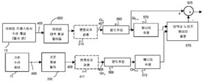
도 2a는 추정된 대역내 노이즈의 추정 및 억제를 통한 입력 파형의 엔벨로프에 대한 노이즈 감소를 위한 예시적인 시스템 구성을 예시하며, 여기서 대역내 노이즈는 대역외 파형의 엔벨로프 검출을 수행하는 것, 그에 뒤이은 감산 이전의 지연, 스케일 및 형상 조정에 의해 추정된다.
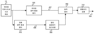
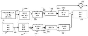
도 2b는 대역내 노이즈의 추정 및 감산을 통한 입력 파형에 대한 노이즈 감소를 위한 예시적인 시스템 구성을 예시하며, 여기서 대역내 노이즈는 대역외 파형을 주파수 시프팅시키는 것, 주파수 시프팅된 대역외 파형을 필터링하는 것, 그에 뒤이은 감산 이전의 지연, 스케일 및 형상 조정에 의해 추정된다.
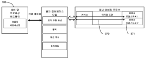
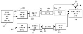
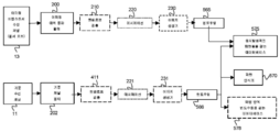
도 2c는 이미징 트랜스듀서 수신 회로가 민감해하지만 이미징 트랜스듀서 수신 회로에 의해 검출된 이미징 신호들로부터 적어도 부분적으로 격리된 대역내 노이즈의 일부 또는 전부에 민감한 기준 수신 회로를 사용한 노이즈 감소를 위한 시스템 구성의 예를 예시하고 있다. 기준 수신 회로에 의해 검출된 노이즈 신호들을 이미징 트랜스듀서 수신 회로에 의해 수신된 신호들로부터 감산하는 것은 출력 신호에서의 노이즈를 감소시킨다.
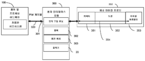
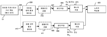
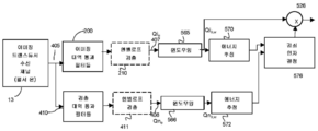
도 3a는 능동 노이즈 소거(active noise cancellation)를 통한 노이즈 감소를 위한 시스템 구성의 예를 예시하며, 여기서 능동 노이즈 소거를 위한 소거 파형은 기준 수신 회로로부터 획득된다.
도 3b는 능동 노이즈 소거를 통한 입력 파형에 대한 노이즈 감소를 위한 시스템 구성의 예를 예시하며, 여기서 능동 노이즈 소거를 위한 소거 파형은 대역외 파형의 엔벨로프 검출에 의해 획득된다.
도 3c는 능동 노이즈 소거를 통한 입력 파형에 대한 노이즈 감소를 위한 시스템 구성의 예를 예시하며, 여기서 능동 노이즈 소거를 위한 소거 파형은 대역외 파형을 주파수 시프팅시키고 주파수 시프팅된 대역외 파형을 필터링하는 것에 의해 획득된다.
도 4는 대역내 파형의 필터링을 통한 입력 파형에 대한 노이즈 감소를 위한 시스템 구성의 예를 예시하며, 여기서 필터링은 노이즈 검출 파형의 하나 이상의 특성에 기초하여 필터의 하나 이상의 파라미터를 결정하는 필터 업데이트 알고리즘에 의해 획득된 피드백 파라미터에 기초하여 제어된다.
도 5a는 이미징 신호의 부재 시에 제1 측정 스테이지 동안 획득된 노이즈 파라미터들에 기초하여, 그리고 이미징 신호들이 수집될 때 제2 측정 스테이지 동안 전술한 노이즈 파라미터들을 이용하는 하나 이상의 노이즈 감소 알고리즘의 적용에 의해 입력 파형에 대한 노이즈 감소를 위한 예시적인 시스템 구성을 개략적으로 예시하고 있다.
도 5b는 기준 수신 채널이 대역내 노이즈를 검출하는 데 이용되는 대안의 예시적인 시스템을 개략적으로 예시하고 있다.
도 6a 및 도 6c는 대역외 파형의 각자의 윈도우의 프로세싱에 기초하여, 대역내 파형의 상이한 시간 윈도우들이 억제되는, 대역외 파형에서의 노이즈의 검출에 기초한 입력 파형에 대한 노이즈 감소를 위한 예시적인 시스템 구성을 예시하며, 여기서 대역내 파형의 노이즈 윈도우들은 대역외 파형의 윈도우 내의 전력 양에 의존하는 감수 값(subtrahend value)을 사용하여 감산하는 것에 의해 보정된다.
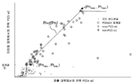
도 6b는 노이즈 특성화 스테이지에서 대역내 파형의 윈도우들의 신호 전력 대 대역외 파형의 각자의 윈도우들의 신호 전력을 보여주는 예시적인 산점도(scatter plot)를 예시하고 있다.
도 6d는 대역외 파형의 각자의 윈도우의 프로세싱에 기초하여, 대역내 파형의 상이한 시간 윈도우들이 억제되는, 대역외 파형에서의 노이즈의 검출에 기초한 입력 파형에 대한 노이즈 감소를 위한 예시적인 시스템 구성을 예시하며, 여기서 대역내 파형의 노이즈 윈도우들은 대역외 파형의 윈도우 내의 전력 양에 의존하는 감쇠 인자(attenuation factor)와 곱하는 것에 의해 보정된다.
도 6e 및 도 6f는 대역내 파형의 상이한 시간 윈도우들이 초기에 주로 신호 또는 노이즈인 것으로 식별되고, 그 후에 신호 윈도우들에 의해 둘러싸인 노이즈 윈도우들이 잘못된 것일 가능성이 있는 것으로 식별되어 재분류되고, 반대로 노이즈 윈도우들에 의해 둘러싸인 신호 윈도우들이 잘못된 것으로 식별되어 노이즈로서 재분류되는 방법에 관한 차트들을 도시하고 있다.
도 6g 및 도 6h는 기준 파형의 각자의 윈도우의 프로세싱에 기초하여, 대역내 파형의 상이한 시간 윈도우들이 억제되는, 기준 수신 채널로 측정되는 필터링된 기준 파형에서의 노이즈의 검출에 기초한 입력 파형에 대한 노이즈 감소를 위한 예시적인 시스템 구성을 예시하며, 여기서 대역내 파형의 노이즈 윈도우들은 필터링된 기준 파형의 윈도우 내의 전력 양에 의존하는 감수 값을 사용하여 감산하는 것에 의해 보정된다.
도 6i는 필터링된 기준 파형의 각자의 윈도우의 프로세싱에 기초하여, 대역내 이미징 파형의 상이한 시간 윈도우들이 보정되는, 기준 수신 채널로 측정되는 필터링된 기준 파형에서 측정된 노이즈에 기초한 입력 파형에 대한 노이즈 감소를 위한 예시적인 시스템 구성을 예시하며, 여기서 대역내 이미징 파형의 노이즈 윈도우들은 필터링된 기준 파형의 윈도우 내의 전력 양에 의존하는 감쇠 인자에 의해 보정된다.
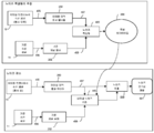
도 7a 및 도 7b는 하나 이상의 노이즈 검출 파형 - 이들 중 적어도 하나의 노이즈 검출 파형은 이미징 대역의 대역외에 있는 신호들을 포함함 - 에서 검출된 노이즈에 기초한 입력 파형에 대한 노이즈 감소를 위한 예시적인 시스템 구성을 예시하고 있다. 대역내 파형의 상이한 시간 윈도우들은 하나 이상의 노이즈 검출 파형을 프로세싱하는 것에 의해 식별된 하나 이상의 패턴에 따라 노이즈 감소를 겪는다.
도 7c 및 도 7d는 대역내 이미징 파형의 상이한 시간 윈도우들이 하나 이상의 기준 파형을 프로세싱하는 것에 의해 식별된 하나 이상의 패턴에 따라 노이즈 감소를 겪는, 기준 파형에서 검출된 노이즈에 기초한 입력 파형에 대한 감소를 위한 예시적인 시스템 구성을 예시하고 있다.
도 8a 및 도 8b는 대역내 파형의 상이한 시간 윈도우들이 감소 이전에 시간적으로 정렬되는 추정된 대역내 노이즈에 따라 노이즈 감소를 겪는, 대역외 파형에서 검출된 노이즈에 기초한 입력 파형에 대한 노이즈 감소를 위한 예시적인 시스템 구성을 예시하고 있다.
도 8c 및 도 8d는 대역내 파형의 상이한 시간 윈도우들이 감소 이전에 시간적으로 정렬되는 추정된 대역내 노이즈에 따라 노이즈 감소를 겪는, 필터링된 기준 파형에서 검출된 노이즈에 기초한 입력 파형에 대한 노이즈 감소를 위한 예시적인 시스템 구성을 예시하고 있다.
도 8e는 노이즈 보정을 수행할 때 인접 또는 복제(replicate) 스캔 라인들로부터의 척도들이 이용되는, 대역외 파형에서 검출된 노이즈에 기초한 입력 파형에 대한 노이즈 감소를 위한 예시적인 시스템 구성을 도시하고 있다.
도 8f는 노이즈 보정을 수행할 때 인접 또는 복제 스캔 라인들로부터의 척도들이 이용되는, 필터링된 기준 파형에서 검출된 노이즈에 기초한 입력 파형에 대한 노이즈 감소를 위한 예시적인 시스템 구성을 도시하고 있다.
도 9는 노이즈 억제를 위해 구성된 자기 공명 이미징 시스템의 예를 도시하고 있다.
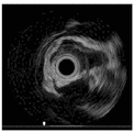
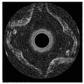
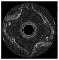
도 10a 내지 도 10c는 (A) 노이즈 소스의 부재 시에 획득된 이미지; (B) 전기해부학적 매핑 시스템(electroanatomic mapping system)을 통해 생성된 노이즈의 존재 시에 획득된 이미지; 및 (C) 어블레이션 생성기(ablation generator)로부터 생성된 노이즈의 존재 시에 획득된 이미지를 보여주는 심장내 초음파 시스템(intra-cardiac echo system)을 사용하여 획득된 예시적인 이미지들을 도시하고 있다.
도 11a 및 도 11b는, (A) 노이즈 감소를 갖지 않는 및 (B) 노이즈 감소를 갖는, 전기해부학적 매핑 시스템으로부터의 노이즈의 존재 시에 획득된 이미지들을 도시하고 있다.
도 11c 내지 도 11e는 감쇠에 의한 노이즈 감소 이후의 전기해부학적 매핑 시스템으로부터의 노이즈의 존재 시에 획득된 이미지들을ㄹ 도시하며, 여기서 완화 파라미터(relaxation parameter)는 0.5(C), 1(D) 및 1.5(E)로서 설정되었다.
도 12a 및 도 12b는, (A) 노이즈 감소 방법의 적용을 갖지 않는 및 (B) 노이즈 감소 방법의 적용을 갖는, 어블레이션 생성기로부터의 노이즈의 존재 시에 획득된 이미지들을 도시하고 있다.
도 13a 및 도 13b는, (A) 노이즈 감소 방법의 적용을 갖지 않는 및 (B) 노이즈 감소 방법의 적용을 갖는, 자기 트래킹 시스템으로부터의 노이즈의 존재 시에 획득된 이미지들을 도시하고 있다.
도 14는 이미징 대역, 노이즈 검출 대역에서의 파형들 및 기준 수신 회로로부터의 파형들을 지칭하는 데 사용되는 문구들을 도시하고 있다.Embodiments will now be described by way of example only with reference to the drawings:
1A shows an example of an ultrasonic imaging system configured for noise suppression.
FIG. 1B shows an example of a conventional ultrasonic receive signal chain for processing an ultrasonic signal prior to conversion to an ultrasonic image.
1C illustrates an example of an ultrasound imaging system that includes an in vivo imaging probe.
1D shows an example of an ultrasonic imaging system including a reference transducer for detecting in-band noise.
FIG. 1E shows an example of an ultrasound imaging system including a second imaging transducer having an imaging band outside the imaging band of the first imaging transducer. The second imaging transducer may be part of a circuit suitable for detecting in-band noise affecting signals received from the first imaging transducer.
1F shows an example of an ultrasonic imaging system that includes a reference receiving circuit for detecting in-band noise, where the reference receiving circuit extends to a location in the imaging probe.
1G shows an example of an ultrasonic imaging system that includes reference receiving circuitry for detecting in-band noise, where the reference receiving circuitry is located in one or more portions of the system outside of the imaging probe.
2A illustrates an example system configuration for noise reduction for an envelope of an input waveform through estimation and suppression of estimated in-band noise, where in-band noise is used to perform envelope detection of an out-of-band waveform. This is estimated by delay, scale and shape adjustment before subtraction.
2B illustrates an exemplary system configuration for noise reduction on an input waveform through estimation and subtraction of in-band noise, where in-band noise is a frequency shifting out-of-band waveform, a frequency shifted out-of-band waveform. Is estimated by filtering, followed by delay, scale and shape adjustment prior to subtraction.
FIG. 2C illustrates a system configuration for noise reduction using a reference receiving circuit, wherein the imaging transducer receiving circuit is sensitive but sensitive to some or all of the in-band noise at least partially isolated from the imaging signals detected by the imaging transducer receiving circuit. An example is given. Subtracting the noise signals detected by the reference receiving circuit from the signals received by the imaging transducer receiving circuit reduces the noise in the output signal.
3A illustrates an example of a system configuration for noise reduction through active noise cancellation, where an erase waveform for active noise cancellation is obtained from a reference receiving circuit.
3B illustrates an example of a system configuration for noise reduction on an input waveform through active noise cancellation, where the cancellation waveform for active noise cancellation is obtained by envelope detection of an out-of-band waveform.
3C illustrates an example of a system configuration for noise reduction on an input waveform through active noise cancellation, wherein the cancellation waveform for active noise cancellation frequency shifts the out-of-band waveform and filters the frequency shifted out-of-band waveform. Obtained by doing.
4 illustrates an example of a system configuration for noise reduction on an input waveform through filtering of an in-band waveform, where the filtering determines a one or more parameters of the filter based on one or more characteristics of the noise detection waveform. It is controlled based on the feedback parameter obtained by.
5A is based on noise parameters obtained during a first measurement stage in the absence of an imaging signal, and by application of one or more noise reduction algorithms using the noise parameters described above during a second measurement stage when imaging signals are collected. An exemplary system configuration for noise reduction on an input waveform is schematically illustrated.
5B schematically illustrates an alternative exemplary system in which a reference receive channel is used to detect in-band noise.
6A and 6C illustrate exemplary noise reduction for an input waveform based on detection of noise in an out-of-band waveform, wherein different time windows of the in-band waveform are suppressed based on processing of respective windows of the out-of-band waveform. Illustrates a system configuration wherein the noise windows of the in-band waveform are corrected by subtracting using a subtrahend value that depends on the amount of power in the window of the out-of-band waveform.
6B illustrates an example scatter plot showing the signal power of the windows of the in-band waveform versus the signal power of the respective windows of the out-of-band waveform in the noise characterization stage.
6D illustrates an example system configuration for noise reduction for an input waveform based on detection of noise in an out-of-band waveform, wherein different time windows of the in-band waveform are suppressed based on processing of respective windows of the out-of-band waveform. Illustrate, where the noise windows of the in-band waveform are corrected by multiplying by an attenuation factor that depends on the amount of power in the window of the out-of-band waveform.
6E and 6F show that different time windows of the in-band waveform are initially identified primarily as signal or noise, and then the noise windows surrounded by the signal windows are identified as likely to be wrong and vice versa. The charts depict how signal windows surrounded by windows are identified as erroneous and reclassified as noise.
6G and 6H illustrate an input waveform based on detection of noise in a filtered reference waveform measured with a reference receive channel, where different time windows of the in-band waveform are suppressed based on processing of respective windows of the reference waveform. Illustrates an exemplary system configuration for noise reduction, where noise windows of an in-band waveform are corrected by subtracting using a subtractive value that depends on the amount of power in the window of the filtered reference waveform.
6I illustrates noise for an input waveform based on measured noise in a filtered reference waveform measured with a reference receiving channel, based on processing of respective windows of the filtered reference waveform, with different time windows of the in-band imaging waveform corrected. Illustrates an exemplary system configuration for reduction, where the noise windows of the in-band imaging waveform are corrected by an attenuation factor that depends on the amount of power in the window of the filtered reference waveform.
7A and 7B illustrate exemplary system configurations for noise reduction on an input waveform based on noise detected in one or more noise detection waveforms, at least one of which includes signals outside the band of the imaging band. To illustrate. Different time windows of the in-band waveform undergo noise reduction according to one or more patterns identified by processing the one or more noise detection waveforms.
7C and 7D illustrate a reduction for an input waveform based on noise detected in a reference waveform, where different time windows of the in-band imaging waveform undergo noise reduction according to one or more patterns identified by processing the one or more reference waveforms. An example system configuration is illustrated.
8A and 8B illustrate noise reduction for an input waveform based on noise detected in an out-of-band waveform, where the different time windows of the in-band waveform undergo a noise reduction according to estimated in-band noise that is aligned in time before the reduction. An example system configuration is illustrated.
8C and 8D illustrate noise reduction for an input waveform based on noise detected in the filtered reference waveform, where the different time windows of the in-band waveform undergo a noise reduction in accordance with the estimated in-band noise that is aligned in time before the reduction. An example system configuration is illustrated.
FIG. 8E illustrates an example system configuration for noise reduction on an input waveform based on noise detected in an out-of-band waveform, in which measures from adjacent or replicate scan lines are used when performing noise correction. .
FIG. 8F illustrates an example system configuration for noise reduction on an input waveform based on noise detected in a filtered reference waveform, in which measures from adjacent or duplicate scan lines are used when performing noise correction.
9 shows an example of a magnetic resonance imaging system configured for noise suppression.
10A-10C are (A) an image obtained in the absence of a noise source; (B) an image obtained in the presence of noise generated via an electroanatomic mapping system; And (C) exemplary images obtained using an intra-cardiac echo system showing images acquired in the presence of noise generated from an ablation generator.
11A and 11B show images obtained in the presence of noise from an electroanalytical mapping system (A) without noise reduction and (B) noise reduction.
11C-11E show images obtained in the presence of noise from an electroanalytical mapping system after noise reduction by attenuation, where the relaxation parameters are 0.5 (C), 1 (D). And 1.5 (E).
12A and 12B show images obtained in the presence of noise from an ablation generator, with (A) no application of the noise reduction method and (B) with the application of the noise reduction method.
13A and 13B show images obtained in the presence of noise from a magnetic tracking system, with (A) no application of the noise reduction method and (B) with the application of the noise reduction method.
14 shows phrases used to refer to waveforms in an imaging band, noise detection band, and waveforms from a reference receiving circuit.
본 개시내용의 다양한 실시예들 및 양태들은 아래에서 논의되는 세부사항들을 참조하여 설명될 것이다. 이하의 설명 및 도면들은 본 개시내용을 예시하며, 본 개시내용을 제한하는 것으로 해석되어서는 안된다. 본 개시내용의 다양한 실시예들에 대한 철저한 이해를 제공하기 위해 수많은 특정 세부사항들이 설명된다. 그렇지만, 특정한 경우들에서, 본 개시내용의 실시예들의 간결한 논의를 제공하기 위해 잘 알려진 또는 종래의 세부사항들은 설명되지 않는다.Various embodiments and aspects of the disclosure will be described with reference to the details discussed below. The following description and drawings illustrate the present disclosure and should not be construed as limiting the disclosure. Numerous specific details are set forth in order to provide a thorough understanding of various embodiments of the present disclosure. However, in certain instances, well known or conventional details are not described in order to provide a concise discussion of embodiments of the present disclosure.
본 명세서에서 사용되는 바와 같이, 용어들 "포함한다" 및 "포함하는"은 포함적이고 개방적이며, 배타적이 아닌 것으로 해석되어야 한다. 구체적으로는, 명세서 및 청구범위에서 사용될 때, 용어들 "포함한다" 및 "포함하는" 및 그 변형들은 명시된 특징들, 단계들 또는 컴포넌트들이 포함된다는 것을 의미한다. 이 용어들은 다른 특징들, 단계들 또는 컴포넌트들의 존재를 배제하는 것으로 해석되어서는 안된다.As used herein, the terms "comprises" and "comprising" are to be interpreted as being inclusive, open, and not exclusive. Specifically, when used in the specification and claims, the terms "comprises" and "comprising" and variations thereof mean that the specified features, steps, or components are included. These terms should not be interpreted to exclude the presence of other features, steps or components.
본 명세서에서 사용되는 바와 같이, 용어 "예시적인"은 "예, 실례 또는 예시로서 역할하는"을 의미하며, 본 명세서에 개시된 다른 구성들보다 바람직하거나 유리한 것으로 해석되어서는 안된다.As used herein, the term "exemplary" means "serving as an example, illustration or illustration," and should not be construed as preferred or advantageous over the other configurations disclosed herein.
본 명세서에서 사용되는 바와 같이, 용어들 "약" 및 "대략"은 속성들, 파라미터들, 및 치수들의 변동들과 같은, 값들의 범위들의 상한 및 하한에 존재할 수 있는 변동들을 커버하는 것으로 의도된다. 달리 명시되지 않는 한, 용어들 "약" 및 "대략"은 +/- 25 % 이하를 의미한다.As used herein, the terms “about” and “approximately” are intended to cover variations that may exist in the upper and lower limits of the range of values, such as variations in attributes, parameters, and dimensions. . Unless otherwise specified, the terms "about" and "approximately" mean up to +/- 25%.
달리 명시하지 않는 한, 임의의 명시된 범위 또는 그룹이 각각의 모든 범위 또는 그룹의 멤버를 개별적으로 지칭하는 것은 물론, 그 안에 포괄되는 각각의 모든 가능한 서브-범위 또는 서브-그룹을 지칭하는 단축된 방식이고, 그 내의 임의의 서브-범위들 또는 서브-그룹들에 대해 이와 유사하다는 것이 이해되어야 한다. 달리 명시되지 않는 한, 본 개시내용은 서브-범위들 또는 서브-그룹들의 각각의 모든 특정 멤버 및 조합에 관련되고 이들을 명시적으로 포함한다.Unless otherwise specified, any shortened range or group refers individually to each and every member of each range or group, as well as to each and every possible sub-range or sub-group encompassed therein. And similar for any sub-ranges or sub-groups therein. Unless otherwise specified, the present disclosure relates to and explicitly includes all particular members and combinations of each of the sub-ranges or sub-groups.
본 명세서에서 사용되는 바와 같이, 용어 "~의 정도"는, 양 또는 파라미터와 관련하여 사용될 때, 언급된 양 또는 파라미터의 대략 10분의 1 내지 10배에 걸치는 범위를 지칭한다.As used herein, the term "degree of", when used in reference to an amount or parameter, refers to a range over approximately one tenth to ten times the stated amount or parameter.
초음파 이미징은, 임의로 매체에서 특정의 방향으로 좁은 음향 펄스를 송신한 후에, 매체로부터 에코들을 수신하는 것에 의존한다. 본 명세서에서 사용되는 바와 같이, 용어 "스캔 라인(scan line)"은 매체 - 이 매체로부터 이미징 에너지가 수신될 것임 - 에서의 공간 방향을 나타내는 라인을 지칭한다. 2D 이미지는 매체 내의 복수의 스캔 라인들로부터 에코들을 수신하는 것에 의해 획득된다. 본 발명자들은 초음파 취득 및/또는 프로세싱 시스템으로부터의 광대역 노이즈를 효과적으로 감소시키는 다양한 방법들 및 시스템들을 고안, 개발 및 테스팅하였다.Ultrasound imaging relies on receiving echoes from the medium, optionally after transmitting narrow acoustic pulses in a particular direction in the medium. As used herein, the term “scan line” refers to a line indicating the spatial direction in a medium, where imaging energy will be received from the medium. The 2D image is obtained by receiving echoes from the plurality of scan lines in the medium. We devised, developed, and tested various methods and systems that effectively reduce broadband noise from an ultrasound acquisition and / or processing system.
이제 도 1a를 참조하면, 하나 이상의 초음파 트랜스듀서(10)가 복수의 스캔 라인들(12)에 걸쳐 초음파 이미징을 수행하도록 제어되는, 예시적인 초음파 이미징 시스템이 도시되어 있다. 트랜스듀서(10)는 제어 및 프로세싱 하드웨어(100)와 인터페이싱하며, 제어 및 프로세싱 하드웨어(100)은 트랜스듀서(10)에 의한 이미징 에너지의 생성 및 방출을 위해 송신기(15)를 임의로 제어한다. 제어 및 프로세싱 하드웨어(100)는, 전형적으로 Tx/Rx(송수신) 스위치(25)를 통해, 하나 이상의 증폭기(20)로 라우팅되는, 트랜스듀서(10)에 의해 검출된 초음파 에너지 신호들을 수신하도록 구성된다.Referring now to FIG. 1A, an exemplary ultrasonic imaging system is shown in which one or more
초음파 트랜스듀서(들)(10)는, 예를 들어, 트랜스듀서(10)의 기계적 스캐닝을 통해, 또는, 예를 들어, 비제한적인 예시로서, 위상 어레이(phased array), 링 어레이(ring array), 선형 어레이(linear array), 매트릭스 어레이(matrix array) 또는 곡선형 어레이(curvilinear array)와 같은, 이미징 요소들의 어레이의 사용을 통한 전자 스캐닝을 통해, 복수의 스캔 라인들(12)과 연관된 공간 영역을 이미징하도록 임의로 구성될 수 있다. 후자의 경우에, 송신 빔포머(transmit beamformer)(26) 및 수신 빔포머(receive beamformer)(27)는 복수의 송신 신호들을 생성하고 복수의 수신된 신호들을 빔포밍하는 데 이용될 수 있다.The ultrasonic transducer (s) 10 may be, for example, through a mechanical scanning of the
본 명세서에서 사용되는 바와 같은, 용어 "수신 회로(receive circuit)"는 일반적으로 전송 라인(예컨대, 동축, PCB 트레이싱들, 다른 것들), 커넥터들, mux/demux, RX/TX 스위치들(25), 증폭기들(20), 슬립 링(slip ring), 변압기들 및 본 기술분야에 공지된 다른 컴포넌트들과 같은 컴포넌트들을 지칭한다. As used herein, the term “receive circuit” generally refers to a transmission line (eg, coaxial, PCB tracings, others), connectors, mux / demux, RX / TX switches 25 , Components such as
본 명세서에서 사용되는 바와 같은, 용어 "트랜스듀서 수신 회로(transducer receive circuit)"는 사용 시에 초음파 신호들을 수신하도록 구성된 하나 이상의 초음파 트랜스듀서 요소(10)에 접속된 수신 회로를 포함할 수 있다.As used herein, the term “transducer receive circuit” may include a receiving circuit connected to one or more
본 명세서에서 사용되는 바와 같은, 어구 "초음파 수신 신호 체인(ultrasound receive signal chain)"은 수신 회로를 포함하지만, 신호가 (스캔 변환(scan conversion)을 통하는 것과 같은) 이미지로 변환되는 프로세스 및 후속 이미지 프로세싱에 들어가기 전에, 아날로그-디지털 변환기들(ADC들)과 같은 부가의 컴포넌트들 및, 노이즈 제거 프로세싱 모듈(150)을 포함하지만, 이들로 제한되지 않는, 추가의 디지털 프로세싱 컴포넌트들 및/또는 프로세싱 로직을 포함할 수 있다.As used herein, the phrase “ultrasound receive signal chain” includes a receiving circuit, but the process and subsequent images in which the signal is converted into an image (such as through a scan conversion). Additional components, such as analog-to-digital converters (ADCs), and additional digital processing components and / or processing logic, including but not limited to noise canceling
본 명세서에서 사용되는 바와 같이, 용어 "채널(channel)"은 전도성 전기 회로들, 무선 채널들, 광학 채널들, 또는 다른 신호 경로들을 지칭할 수 있다. 예를 들어, 검출된 이미징 신호들에 의해 통과되는(traversed) 경로를 표기하는, 이미징 수신 채널이 도 1a에서 13에 도시되어 있다. 이 시스템은 (어레이 내의 각각의 압전 트랜스듀서 요소 또는 압전 트랜스듀서 요소 그룹들을 위한 채널이 있을 수 있는 어레이 트랜스듀서에 대해 그러할 수 있는 바와 같이) 트랜스듀서당 단일 수신 채널, 또는 트랜스듀서당 몇 개의 수신 채널을 이용할 수 있다. ASIC들 및 다른 디바이스들은 하나 초과의 압전 트랜스듀서 요소로부터의 채널을 따라 신호들을 다중화하기 위해 신호 수신 체인을 따라 사용될 수 있다.As used herein, the term “channel” may refer to conductive electrical circuits, wireless channels, optical channels, or other signal paths. For example, an imaging receive channel, which indicates the path traversed by detected imaging signals, is shown at 13 in FIG. 1A. The system is a single receive channel per transducer, or several receive per transducer (as may be the case for array transducers, where there may be a channel for each piezoelectric transducer element or piezoelectric transducer element groups in an array). Channels are available. ASICs and other devices can be used along a signal receive chain to multiplex signals along a channel from more than one piezoelectric transducer element.
"이미징 모드(imaging mode)"에서, 이 시스템은 에너지를 매체로 임의로 전송하도록해, 그리고 이미징 주파수 대역(이후 "이미징 대역(imaging band)"이라고 지칭됨) 내부의 이미징 에너지를 검출하도록 트랜스듀서(10)를 제어하도록 구성될 수 있다. 이미징 대역은, 이미징 에너지가 검출되는, 단일 연속 주파수 대역, 또는 (고조파 이미징에서와 같은) 2개 이상의 주파수 간격을 구성할 수 있다. 이미징 대역 내부의 이미징 에너지 또는 노이즈는 이후부터 "대역내(in-band)"인 것으로 지칭된다.In "imaging mode", the system allows the transducer to randomly transmit energy to the medium and to detect imaging energy inside the imaging frequency band (hereafter referred to as the "imaging band"). 10). The imaging band may constitute a single continuous frequency band, or two or more frequency intervals (as in harmonic imaging), in which imaging energy is detected. Imaging energy or noise inside the imaging band is hereinafter referred to as "in-band".
도 14는 다양한 파형들을 설명하는 데 사용되는 그룹화 및 용어의 표현이다.14 is a representation of groupings and terms used to describe various waveforms.
이 시스템은, 트랜스듀서에 접속된 하나 이상의 채널을 통해, 하나 이상의 부가의 주파수 대역에서 에너지를 검출하도록 또한 구성될 수 있으며, 여기서 적어도 하나의 주파수 대역은, 적어도 부분적으로, 이미징 대역을 벗어나 있다. 이러한 하나 이상의 부가의 주파수 대역은 이후부터 "검출 대역(detection band)"이라고 지칭된다. 이미징 대역을, 적어도 부분적으로, 벗어나 있는 파형은 이후부터 "대역외(out-of-band)"인 것으로 지칭된다. 일부 경우들에서, 검출 대역은 이미징 대역 내부에 존재할 수 있다. 주파수 성분들이 이미징 대역 전체 내부에 또는 이미징 대역 내부의 서브대역들에 있는, 전체적으로 이미징 대역 내부에 있는 파형은 이후부터 "대역 내부(within-band)"인 것으로 지칭된다. 노이즈 검출 대역들은 대역외 또는 대역 내부일 수 있다. 트랜스듀서가 이미징 모드에서 사용될 때(즉, 트랜스듀서가 이미징 에너지를 검출할 때) 검출 대역 내부에서의 신호대 노이즈비가 이미징 대역에서의 신호대 노이즈비보다 실질적으로 작도록 적어도 하나의 검출 대역이 선택될 수 있다. 예를 들어, 검출 대역은 이미징 대역의 반치전폭(full-width, half-maximum) 대역폭 또는 이용된 신호의 최대 세기 미만의 임계값에 대응하는 다른 대역폭 밖에 있을 수 있다.The system may also be configured to detect energy in one or more additional frequency bands, via one or more channels connected to the transducer, wherein at least one frequency band is at least partially out of the imaging band. One or more such additional frequency bands are hereinafter referred to as "detection bands". Waveforms that are at least partially out of the imaging band are hereinafter referred to as "out-of-band". In some cases, the detection band may exist inside the imaging band. Waveforms that are entirely within the imaging band, whose frequency components are within the entire imaging band or in subbands within the imaging band, are hereinafter referred to as "within-band". The noise detection bands may be out of band or in band. When the transducer is used in imaging mode (ie when the transducer detects imaging energy) at least one detection band may be selected such that the signal-to-noise ratio inside the detection band is substantially less than the signal-to-noise ratio in the imaging band. have. For example, the detection band may be outside the full-width, half-maximum bandwidth of the imaging band or other bandwidth corresponding to a threshold below the maximum intensity of the signal used.
본 명세서에서 사용되는 바와 같이, "이미징 파형(imaging waveform)"은 이미징 트랜스듀서가 이미징 에너지를 수신하고 있거나 이미징 에너지를 수신할 것으로 예상될 때 이미징 트랜스듀서 수신 회로로부터 획득되는 파형(아날로그 또는 디지털적으로 샘플링됨)을 지칭한다.As used herein, an "imaging waveform" is a waveform (analog or digital) obtained from an imaging transducer receiving circuit when the imaging transducer is receiving or is expected to receive imaging energy. Sampled as).
본 명세서에서 사용되는 바와 같이, 문구 "대역내 이미징 파형(in-band imaging waveform)"은 이미징 대역 내에 있는 이미징 파형(아날로그 또는 디지털적으로 샘플링됨)을 지칭한다. 대역내 이미징 파형은 이미징 에너지를 포함할 것으로 예상되며 원하지 않는 노이즈 에너지를 또한 포함할 수 있다. 본 개시내용의 다양한 예시적인 실시예들에서, 디노이징된 이미지의 생성을 위한 노이즈 에너지를 제거하기 위해 대역내 이미징 파형이 프로세싱된다.As used herein, the phrase “in-band imaging waveform” refers to an imaging waveform (analog or digitally sampled) within the imaging band. In-band imaging waveforms are expected to include imaging energy and may also include unwanted noise energy. In various exemplary embodiments of the present disclosure, an in-band imaging waveform is processed to remove noise energy for generation of a denoised image.
본 명세서에서 사용되는 바와 같이, 문구 "검출 대역 이미징 파형(detection-band imaging waveform)"은 이미징 트랜스듀서 수신 채널로부터 획득되고 하나 이상의 노이즈 검출 대역 내부에 존재하는 파형을 지칭한다. 검출 대역 이미징 파형은 대역외 또는 대역 내부일 수 있다. 예를 들어, 이미징 대역 내부에서의 노이즈의 존재를 확인하기 위해, 대역 내부 노이즈 검출 이미징 파형이 이용될 수 있다. 보다 구체적으로는, 이미징 대역 밖에 있는 노이즈 성분을 갖는 노이즈 소스가 이미징 대역 내부의 노이즈 성분을 또한 갖는다는 것을 확인하기 위해 "대역 내부 노이즈 검출 이미징 파형(within-band noise-detection imaging waveform)"이 이용될 수 있다. 적어도 부분적으로, 이미징 대역 밖에 있는 검출 대역 이미징 파형은 "대역외 노이즈 검출 파형(out-of-band noise-detection waveform)"이라고 지칭된다.As used herein, the phrase “detection-band imaging waveform” refers to a waveform obtained from an imaging transducer receive channel and present within one or more noise detection bands. The detection band imaging waveform can be out of band or in band. For example, in-band noise detection imaging waveforms may be used to confirm the presence of noise inside the imaging band. More specifically, the "within-band noise-detection imaging waveform" is used to confirm that noise sources with noise components outside the imaging band also have noise components inside the imaging band. Can be. At least in part, a detection band imaging waveform outside the imaging band is referred to as an "out-of-band noise-detection waveform."
도 1a를 참조하면, 이 시스템은 "노이즈 특성화 모드(noise-characterization mode)"에 있도록 구성될 수 있으며, 이 모드 동안 트랜스듀서(10)는 에너지를 매체로 전송하지 않고 매체로부터의 이미징 에너지를 검출하지 않는다.Referring to FIG. 1A, the system may be configured to be in a “noise-characterization mode” during which the
본 명세서에서 사용되는 바와 같이, 문구 "노이즈 특성화 파형(noise-characterization waveform)"은 이미징 트랜스듀서가 이미징 에너지를 수신하지 않을 때 획득되는 파형을 지칭한다.As used herein, the phrase “noise-characterization waveform” refers to the waveform obtained when the imaging transducer does not receive imaging energy.
본 명세서에서 사용되는 바와 같이, 문구 "대역내 노이즈 특성화 파형(in-band noise-characterization waveform)"은 이미징 트랜스듀서가 이미징 에너지를 수신하지 않을 때 이미징 트랜스듀서 수신 채널로부터 획득되는, 이미징 대역에 존재하는 파형을 지칭한다.As used herein, the phrase “in-band noise-characterization waveform” exists in the imaging band, which is obtained from the imaging transducer receiving channel when the imaging transducer does not receive imaging energy. Refers to the waveform.
본 명세서에서 사용되는 바와 같이, 문구 "검출 대역 노이즈 특성화 파형(detection-band noise-characterization waveform)"은 이미징 트랜스듀서가 이미징 에너지를 수신하지 않을 때 이미징 트랜스듀서 수신 채널로부터 획득되는, 노이즈 검출 대역에 존재하는 파형을 지칭한다. 적어도 부분적으로, 이미징 대역 밖에 있는 검출 대역 노이즈 특성화 파형은 "대역외 노이즈 특성화 파형(out-of-band noise characterization waveform)"이라고 지칭된다. 전체적으로 이미징 대역 내부에 있는 검출 대역 노이즈 특성화 파형은 "대역 내부 노이즈 특성화 파형(within-band noise characterization waveform)"이라고 지칭된다.As used herein, the phrase “detection-band noise-characterization waveform” refers to a noise detection band, which is obtained from an imaging transducer receiving channel when the imaging transducer does not receive imaging energy. Refers to a waveform present. At least in part, the detection band noise characterization waveform outside the imaging band is referred to as an "out-of-band noise characterization waveform." The detection band noise characterization waveform, which is entirely inside the imaging band, is referred to as a "with in-band noise characterization waveform".
본 명세서에서 사용되는 바와 같이, 문구 "베이스라인 노이즈 특성화 파형(baseline noise-characterization waveform)"은, 베이스라인 노이즈 특성화 파형이 선택된 노이즈 소스에 대한 베이스라인을 제공하도록, 이미징 트랜스듀서가 이미징 에너지를 수신하고 있지 않을 때, 그리고 선택된 노이즈 소스가 오프일 것으로 예상될 때(즉, 노이즈 생성의 부재) 획득되는 파형을 지칭한다, 이미징 대역 내에 있는 베이스라인 노이즈 특성화 파형을 "대역내 베이스라인 노이즈 특성화 파형(in-band baseline noise-characterization waveform)"이라고 지칭된다. 노이즈 검출 대역 내에 있는 베이스라인 노이즈 특성화 파형은 "검출 대역 베이스라인 노이즈 특성화 파형(detection-band baseline noise-characterization waveform)"이라고 지칭된다.As used herein, the phrase “baseline noise-characterization waveform” refers to the imaging transducer receiving imaging energy such that the baseline noise characterization waveform provides a baseline for the selected noise source. Refers to a waveform that is obtained when it is not doing, and when the selected noise source is expected to be off (ie, the absence of noise generation). in-band baseline noise-characterization waveform). The baseline noise characterization waveform within the noise detection band is referred to as a "detection-band baseline noise-characterization waveform."
도 1a를 다시 참조하면, 이미징 동안 하나 이상의 트랜스듀서 수신 회로에 커플링되는 노이즈와 유사한 노이즈 에너지를 검출할 수 있으면서, 이미징 동안 반사된 초음파 신호들을 수신하지 않도록 구성된 수신 회로를 포함하는 임의적 기준 수신 회로(11)가 제공될 수 있다. 기준 수신 회로는 트랜스듀서 수신 회로의 하나 이상의 컴포넌트를 이용할 수 있다(예를 들어, 기준 수신 회로 및 트랜스듀서 수신 회로는 증폭기 또는 ADC의 상이한 채널들을 이용할 수 있다).Referring again to FIG. 1A, an optional reference receiving circuit comprising a receiving circuit configured to not receive reflected ultrasonic signals during imaging while being capable of detecting noise energy similar to noise coupled to one or more transducer receiving circuits during imaging. (11) may be provided. The reference receiving circuit may use one or more components of the transducer receiving circuit (eg, the reference receiving circuit and the transducer receiving circuit may use different channels of the amplifier or ADC).
하나의 예시적인 구현에서, 이 시스템은, 반사된 초음파(reflected ultrasound wave)를 트랜스듀싱(transduce)하지 않도록 음향적으로 격리되거나 비활성화되지만 이미징 트랜스듀서 수신 회로에 의해 수신된 노이즈에 민감한 기준 초음파 트랜스듀서(도시되지 않음)에 임의로 접속되는, 하나 이상의 기준 수신 채널을 통해 이미징 대역 내부에서 노이즈를 검출하도록 구성될 수 있다. 하나 이상의 이미징 트랜스듀서(10) 및 하나 이상의 기준 트랜스듀서는 공통의 공간 방향으로 배향될 필요가 없다.In one exemplary implementation, the system is a reference ultrasonic transducer that is acoustically isolated or deactivated to not transduce the reflected ultrasound wave but is sensitive to noise received by the imaging transducer receiving circuitry. It may be configured to detect noise inside the imaging band via one or more reference receive channels, optionally connected to (not shown). One or
하나 이상의 기준 트랜스듀서 수신 회로 또는 기준 전기 수신 회로에 의해 (기준 수신 채널을 통해) 수신된 신호들은 이후부터 기준 파형들이라고 지칭된다. 기준 파형은 주로 노이즈이며 이미징 에너지가 아니다.Signals received (via a reference receiving channel) by one or more reference transducer receiving circuits or reference electrical receiving circuits are hereinafter referred to as reference waveforms. The reference waveform is mainly noise and not imaging energy.
본 명세서에서 사용되는 바와 같이, 문구 "기준 파형(reference waveform)"은 하나 이상의 기준 수신 채널로부터 획득된 파형을 지칭한다. 기준 파형은 이미징 대역 내부에 그리고/또는 이미징 대역 밖에 존재하도록 필터링될 수 있다.As used herein, the phrase “reference waveform” refers to a waveform obtained from one or more reference receive channels. The reference waveform may be filtered to be inside the imaging band and / or outside the imaging band.
본 명세서에서 사용되는 바와 같이, 문구 "기준 노이즈 검출 파형(reference noise-detection waveform)"은 이미징 트랜스듀서가 이미징 에너지를 수신하고 있거나 수신할 것으로 예상될 때 기준 수신 채널로부터 획득된 기준 파형을 지칭한다.As used herein, the phrase “reference noise-detection waveform” refers to a reference waveform obtained from a reference receive channel when the imaging transducer is or is expected to receive imaging energy. .
본 명세서에서 사용되는 바와 같이, 문구 "기준 노이즈 특성화 파형(reference noise-characterization waveform)"은 이미징 트랜스듀서가 이미징 에너지를 수신하고 있지 않을 때 기준 수신 채널로부터 획득된 기준 파형을 지칭한다.As used herein, the phrase “reference noise-characterization waveform” refers to a reference waveform obtained from a reference receive channel when the imaging transducer is not receiving imaging energy.
이 시스템은 검출 대역 파형들 및 기준 파형들의 조합을 사용하여 노이즈를 억제하도록 임의로 구성될 수 있다. 본 명세서에서 사용되는 바와 같이, 문구 "노이즈 검출 파형(noise-detection waveform)"은 기준 파형 또는 검출 대역 파형을 지칭한다. 이 시스템이 이미징 모드에 있고 이미징 트랜스듀서 수신 회로가 이미징 에너지를 수신하고 있거나 수신할 것으로 예상될 때, 노이즈 검출 파형은 "노이즈 검출 이미징 파형(noise-detection imaging waveform)"이라고 지칭된다. 이 시스템이 노이즈 특성화 모드에 있고 이미징 트랜스듀서 수신 회로가 이미징 에너지를 수신하고 있지 않을 때, 노이즈 검출 파형은 "노이즈 검출 특성화 파형(noise-detection characterization waveform)"이라고 지칭된다.The system can be arbitrarily configured to suppress noise using a combination of detection band waveforms and reference waveforms. As used herein, the phrase “noise-detection waveform” refers to a reference waveform or a detection band waveform. When the system is in imaging mode and the imaging transducer receiving circuit is or is expecting to receive imaging energy, the noise detection waveform is referred to as a "noise-detection imaging waveform." When this system is in a noise characterization mode and the imaging transducer receiving circuit is not receiving imaging energy, the noise detection waveform is referred to as a "noise-detection characterization waveform."
비록 도 1a가 단일 트랜스듀서 요소를 도시하고 있지만, 도 1a에 도시된 실시예가 단지 하나의 비제한적인 예시적인 구성을 제공할 뿐이고, 다수의 압전 요소들을 갖는 트랜스듀서들이 이용될 수 있음이 이해될 것이다. 예를 들어, 하나의 예시적인 실시예에서, 복수의 트랜스듀서 요소들은 위상 어레이 또는 선형 어레이 또는 2D 어레이로서 제어될 수 있다. 게다가, 트랜스듀서는 다차원 2D 단면 이미지들 또는 3D 볼륨들(시간에 따른 3D 이미지들을 포함하는 4D 이미징 데이터 세트들을 포함함)을 생성하는 목적을 위해 이미징 에너지를 전송하는 것으로 제한되지 않을 수 있고, 흐름의 도플러 평가에 사용되는 트랜스듀서들, (예컨대, 전체가 참고로 포함되는, 발명의 명칭이 "Active localization and visualization of minimally invasive devices using ultrasound"인 미국 특허 공개 제2016/0045184호에 설명된 바와 같은) 초음파 비컨들로서 사용되는 트랜스듀서들, 또는 (예컨대, 전체가 참고로 포함되는, 발명의 명칭이 "Ultrasonic probe with ultrasonic transducers addressable on common electrical channel"인 미국 특허 공개 제2012/0197113호에 설명된 바와 같은) 움직이는 요소들의 위치를 감지하는 데 사용되는 초음파 트랜스듀서들을 포함할 수 있다.Although FIG. 1A shows a single transducer element, it is to be understood that the embodiment shown in FIG. 1A provides only one non-limiting example configuration and that transducers having multiple piezoelectric elements may be used. will be. For example, in one exemplary embodiment, the plurality of transducer elements can be controlled as a phased array or a linear array or a 2D array. In addition, the transducer may not be limited to transmitting imaging energy for the purpose of generating multidimensional 2D cross-sectional images or 3D volumes (including 4D imaging data sets including 3D images over time), and flow Transducers used in Doppler evaluation of the same, as described in US Patent Publication No. 2016/0045184 (e.g., entitled "Active localization and visualization of minimally invasive devices using ultrasound", which is incorporated by reference in its entirety). Transducers used as ultrasonic beacons, or (such as described in US Patent Publication No. 2012/0197113, entitled "Ultrasonic probe with ultrasonic transducers addressable on common electrical channel", which is incorporated by reference in its entirety) And ultrasonic transducers used to sense the position of the moving elements.
트랜스듀서는 도 1a에 도시된 바와 같이 이미징 에너지를 전송하기도 하고 수신하기도 하는 것으로 제한되지 않을 수 있고, 광학 에너지(광음향 이미징(photoacoustic imaging))와 같은, 다른 수단에 의해, 또는 별개의 초음파 트랜스듀서에 의해 여기된 매체로부터 초음파 에너지를 수신하는 트랜스듀서들을 포함할 수 있다. 게다가, 비록 도 1a가 상이한 방향들로 복수의 스캔 라인들과 연관된 공간 영역을 이미징하기 위한 구성을 도시하지만, 스캔 라인들은, M-모드 이미징에서 또는, 흐름을 평가하기 위한 펄스파 또는 연속파 도플러와 같은, 특정한 도플러 모달리티들 동안과 같이, 단방향일 수 있다.The transducer may not be limited to transmitting or receiving imaging energy, as shown in FIG. 1A, and may be by other means, such as optical energy (photoacoustic imaging), or by separate ultrasonic transducers. And transducers for receiving ultrasonic energy from a medium excited by the transducer. In addition, although FIG. 1A shows a configuration for imaging a spatial region associated with a plurality of scan lines in different directions, the scan lines are in M-mode imaging or with pulsed or continuous wave Doppler for evaluating flow. May be unidirectional, such as during certain Doppler modalities.
하나의 예시적인 실시예에서, 단일 트랜스듀서 수신 채널은 이미징 대역 내부에서 이미징 에너지를 수신하도록, 그리고 동시발생적으로(coincidentally) 또한 하나 이상의 노이즈 검출 대역 - 이들 중 적어도 하나는 대역외 노이즈를 포함함 - 내부에서 부가의 에너지를 수신하도록 구성된다. 다른 예에서, 하나 이상의 이미징 트랜스듀서 수신 채널은 이미징 대역 내부에서 이미징 에너지를 수신하는 데 이용될 수 있고, 하나 이상의 트랜스듀서 수신 채널은 하나 이상의 노이즈 검출 대역 - 이들 중 적어도 하나는 대역외 노이즈를 포함함 - 내부에서 부가의 에너지를 수신하는 데 이용될 수 있다. 또 다른 예에서, 하나 이상의 기준 수신 채널은 이미징 대역에서 이미징 에너지로부터 격리되어 있으면서 노이즈 에너지(즉, 기준 노이즈 검출 파형들)를 수신하는 데 이용될 수 있다. 기준 수신 채널은 이미징 대역 통과 필터를 사용하여 이미징 트랜스듀서 수신 채널과 유사한 방식으로 필터링될 수 있다. 대안적으로, 몇몇 실시예들에서, 기준 수신 채널이 전혀 필터링되지 않을 수 있거나, 이미징 대역 내부의 노이즈의 추정을 보다 잘 용이하게 하기 위해 이미징 대역 통과 필터와 상이한 필터들을 가질 수 있다.In one exemplary embodiment, a single transducer receive channel is configured to receive imaging energy within the imaging band and simultaneously and at least one noise detection band, at least one of which includes out-of-band noise. Configured to receive additional energy therein. In another example, one or more imaging transducer receive channels can be used to receive imaging energy within the imaging band, wherein the one or more transducer receive channels comprise one or more noise detection bands, at least one of which includes out-of-band noise. May be used to receive additional energy internally. In another example, one or more reference receive channels may be used to receive noise energy (ie, reference noise detection waveforms) while being isolated from imaging energy in the imaging band. The reference receive channel can be filtered in a similar manner to the imaging transducer receive channel using an imaging band pass filter. Alternatively, in some embodiments, the reference receive channel may not be filtered at all, or may have filters different from the imaging bandpass filter to better facilitate estimation of noise inside the imaging band.
제어 및 프로세싱 하드웨어(100)는, 예를 들어, 하나 이상의 프로세서(110), 메모리(115), 시스템 버스(105), 하나 이상의 입/출력 디바이스(120), 및 통신 인터페이스(135), 데이터 취득 인터페이스(140), 디스플레이(125), 및 외부 스토리지(130)와 같은 복수의 임의적인 부가 디바이스들을 포함할 수 있다.Control and
도 1a에 도시된 예시적인 시스템이 비제한적인 예시적인 실시예를 예시하고, 도시된 컴포넌트들로 제한되는 것으로 의도되지 않음이 이해되어야 한다. 예를 들어, 이 시스템은 하나 이상의 부가의 프로세서 및 메모리 디바이스를 포함할 수 있다. 게다가, 제어 및 프로세싱 하드웨어(100)의 하나 이상의 컴포넌트는 프로세싱 디바이스와 인터페이싱되는 외부 컴포넌트로서 제공될 수 있다. 예를 들어, 도면에 도시된 바와 같이, 임의적 송신 빔포머(26) 및 임의적 수신 빔포머(27)가 (파선 내에 도시된 바와 같이) 제어 및 프로세싱 하드웨어(100)의 컴포넌트로서 포함될 수 있거나, 하나 이상의 외부 디바이스로서 제공될 수 있다.It should be understood that the example system shown in FIG. 1A illustrates a non-limiting example embodiment and is not intended to be limited to the illustrated components. For example, the system may include one or more additional processors and memory devices. In addition, one or more components of control and
본 개시내용의 일부 양태들은, 컴퓨팅 시스템 상에서 실행될 때, 컴퓨팅 시스템을 본 명세서에 개시된 신호 프로세싱 및 노이즈 감소 방법들, 또는 그의 변형들을 수행할 수 있는 특수 목적 컴퓨팅 시스템으로서 구성하는 소프트웨어로, 적어도 부분적으로, 구체화될(embodied) 수 있다. 즉, 이 기술들은 컴퓨터 시스템 또는 다른 데이터 프로세싱 시스템에서, 마이크로프로세서, CPU 또는 GPU와 같은, 그의 프로세서가, ROM, 휘발성 RAM, 비휘발성 메모리, 캐시, 자기 및 광학 디스크들, 클라우드 프로세서들, 또는 원격 저장 디바이스들과 같은, 메모리에 들어 있는 명령어들의 시퀀스들을 실행하는 것에 응답하여 수행될 수 있다. 게다가, 명령어들은, 컴파일된 및 링크된 버전의 형태로와 같이, 데이터 네트워크를 통해 컴퓨팅 디바이스로 다운로드될 수 있다. 대안적으로, 위에서 논의된 바와 같은 프로세스들을 수행하는 로직은, LSI들(large-scale integrated circuits), ASIC들(application-specific integrated circuits)로서의 개별 하드웨어 컴포넌트들, 또는 EEPROM들(electrically erasable programmable read-only memory) 및 FPGA들(field-programmable gate arrays)과 같은 펌웨어와 같은, 부가의 컴퓨터 및/또는 머신 판독가능 매체들에서 구현될 수 있다.Some aspects of the disclosure are, at least in part, software that, when executed on a computing system, configures the computing system as a special purpose computing system capable of performing the signal processing and noise reduction methods disclosed herein, or variations thereof. Can be embodied. That is, these techniques can be used in computer systems or other data processing systems, where a processor, such as a microprocessor, CPU or GPU, can be used for ROM, volatile RAM, nonvolatile memory, cache, magnetic and optical disks, cloud processors, or remote. It may be performed in response to executing sequences of instructions contained in memory, such as storage devices. In addition, the instructions may be downloaded to the computing device via a data network, such as in the form of compiled and linked versions. Alternatively, logic to perform the processes as discussed above may be used for large-scale integrated circuits (LSIs), individual hardware components as application-specific integrated circuits (ASICs), or electrically erasable programmable read-outs. and may be implemented in additional computer and / or machine readable media, such as firmware such as only memory and field-programmable gate arrays (FPGAs).
컴퓨터 판독가능 매체는 데이터 프로세싱 시스템에 의해 실행될 때 이 시스템으로 하여금 다양한 방법들을 수행하게 하는 소프트웨어 및 데이터를 저장하는 데 사용될 수 있다. 실행가능 소프트웨어 및 데이터는, 예를 들어, ROM, 휘발성 RAM, 비휘발성 메모리 및/또는 캐시를 포함한 다양한 장소들에 저장될 수 있다. 이 소프트웨어 및/또는 데이터의 부분들은 이러한 저장 디바이스들 중 임의의 것에 저장될 수 있다. 일반적으로, 머신 판독가능 매체는 머신(예컨대, 컴퓨터, 네트워크 디바이스, 개인 휴대 정보 단말(personal digital assistant), 제조 툴(manufacturing tool), 하나 이상의 프로세서들의 세트를 갖는 임의의 디바이스 등)에 의해 액세스가능한 형태로 정보를 제공하는(즉 저장 및/또는 전송하는) 임의의 메커니즘을 포함한다.Computer-readable media can be used to store software and data that, when executed by a data processing system, cause the system to perform various methods. Executable software and data may be stored in various places including, for example, ROM, volatile RAM, nonvolatile memory, and / or cache. Portions of this software and / or data may be stored in any of these storage devices. Generally, a machine readable medium is accessible by a machine (eg, computer, network device, personal digital assistant, manufacturing tool, any device having a set of one or more processors, etc.). And any mechanism for providing (ie storing and / or transmitting) information in the form.
컴퓨터 판독가능 매체들의 예들은, 그 중에서도, 휘발성 및 비휘발성 메모리 디바이스들, 판독 전용 메모리(ROM), 랜덤 액세스 메모리(RAM), 플래시 메모리 디바이스들, 플로피 및 다른 이동식 디스크들, 자기 디스크 저장 매체들, 광학 저장 매체들(예컨대, CD들(compact discs), DVD들(digital versatile disks) 등), 네트워크 어태치 스토리지(network attached storage), 클라우드 스토리지와 같은 기록가능(recordable) 및 비-기록가능(non-recordable) 유형 매체들을 포함하지만 이들로 제한되지 않는다. 명령어들은 전기, 광학, 음향 또는, 캐리어 파들(carrier waves), 적외선 신호들, 디지털 신호들, 및 이와 유사한 것과 같은, 다른 형태들의 전파 신호들을 위한 디지털 및 아날로그 통신 링크들에서 구체화될 수 있다. 본 명세서에서 사용되는 바와 같이, 어구들 "컴퓨터 판독가능 재료" 및 "컴퓨터 판독가능 저장 매체"는, 일시적 전파 신호(transitory propagating signal) 그 자체를 제외한, 모든 컴퓨터 판독가능 매체들을 지칭한다.Examples of computer readable media include, among others, volatile and nonvolatile memory devices, read only memory (ROM), random access memory (RAM), flash memory devices, floppy and other removable disks, magnetic disk storage media. Recordable and non-writable, such as optical storage media (e.g. compact discs, digital versatile disks, etc.), network attach storage, cloud storage, non-recordable) media, including but not limited to. The instructions may be embodied in digital and analog communication links for other forms of propagation signals, such as electrical, optical, acoustical, or carrier waves, infrared signals, digital signals, and the like. As used herein, the phrases “computer readable material” and “computer readable storage medium” refer to all computer readable media, except for the transitory propagating signal itself.
본 명세서에 설명된 실시예들 중 다수는 환경에서 감지된 노이즈에 기초한 노이즈 감소 필터의 조정을 이용한다. 일부 예시적인 구현들에서, 아래의 예시적인 실시예들에서 설명된 파형들, 데이터, 필터 파라미터들 및 다른 관련 정보 중 하나 이상은 네트워크로 전송가능할 수 있고 노이즈 감소 필터 구현의 추가 분석 및/또는 최적화를 위해 원격으로 평가될 수 있다. 일단 최적화되면, 개선된 노이즈 감소를 가능하게 해주기 위해 노이즈 감소 필터 알고리즘들 및/또는 파라미터들이 이어서 이 시스템으로 전송될 수 있다.Many of the embodiments described herein utilize adjustment of a noise reduction filter based on noise sensed in the environment. In some example implementations, one or more of the waveforms, data, filter parameters and other related information described in the example embodiments below may be transmitable to the network and further analysis and / or optimization of the noise reduction filter implementation. Can be evaluated remotely. Once optimized, noise reduction filter algorithms and / or parameters may then be sent to this system to enable improved noise reduction.
도 1a에 도시된 바와 같이, 예시적인 제어 및 프로세싱 하드웨어(100)는 이미징 프로세싱 모듈(145) 및 노이즈 억제 모듈(150)을 포함한다. 이미지 프로세싱 엔진(145)은, 스캔 변환(scan conversion)과 같은, 알려진 이미지 프로세싱 방법들을 실행하도록 구성 또는 프로그래밍될 수 있다.As shown in FIG. 1A, example control and
본 실시예들 중 몇몇이 실시간 노이즈 감소를 가능하게 해주는 방식으로 예시되고 설명되었지만, 노이즈 감소가 포스트-프로세싱(post-processing) 방식으로 발생할 수 있음이 이해되어야 한다. 예를 들어, 트랜스듀서 수신 채널 또는 기준 수신 채널 상의 데이터는 본 발명의 설명된 실시예들에서의 임의의 필터링, 엔벨로프 검출, 시프팅, 형상/위상 또는 지연 조정들, 신호 특성화, 감쇠, 감산 또는 다른 단계들 이전에 또는 그 이후에 디지털화 및 저장될 수 있다.Although some of the embodiments have been illustrated and described in a manner that enables real-time noise reduction, it should be understood that noise reduction may occur in a post-processing manner. For example, data on the transducer receive channel or reference receive channel may be filtered, envelope detected, shifted, shape / phase or delay adjustments, signal characterization, attenuation, subtraction or any of the described embodiments of the invention. It may be digitized and stored before or after other steps.
도 1b는 이미지 생성 이전에 이미징 트랜스듀서 수신 채널로부터의 검출된 대역내 이미징 파형을 프로세싱하기 위해 제어 및 프로세싱 하드웨어(100) 및 수신 채널에 의해 이용될 수 있는 단계들의 예를 예시하고 있다. 이미징 트랜스듀서 수신 회로로부터의 검출된 파형은 아날로그-디지털 변환(203) 이전에 증폭(201)되고 필터링(202)될 수 있다. 일단 디지털화되면, (다수의 통과 대역들 및 저지 대역들을 이용할 수 있는) 대역 통과 필터(200)는 검출된 파형을 필터링하고 이미징 대역에서의 신호를 유지하는 데 이용된다. 필터링된 파형의 엔벨로프는 이어서 엔벨로프 검출기(210)를 통해 생성된다. 결과적인 엔벨로프 검출된 파형은 이어서 임의로 데시메이트(decimated) 또는 확장(expanded)(220)되고 이미지의 생성을 위해 이미지 프로세싱 모듈(230)에 제공된다.1B illustrates an example of steps that may be used by the control and
도 1a를 다시 참조하면, 예시적인 제어 및 프로세싱 하드웨어(100)는 하나 이상의 노이즈 억제 모듈(150)을 포함하고, 노이즈 억제 모듈(150)은, 아래에서 상세히 설명되는 노이즈 감소 알고리즘들에 따라, 노이즈의 기여분을 감소시키기 위해 검출된 데이터(예컨대, 원시 RF 데이터, 엔벨로프 데이터, 또는 이미지 데이터)를 프로세싱하기 위한 명령어들을 포함한다. 아래에서 설명되는 바와 같이, 본 명세서에 개시된(및 도 1a에 노이즈 억제 모듈(150)로 나타내어진) 노이즈 억제 알고리즘들은, 하나 이상의 노이즈 검출 파형을 프로세싱한 것에 기초하여, 도 1b에 도시된 프로세싱 흐름 동안 몇 개의 잠재적 단계에서 노이즈를 제거 또는 감소시키는 데 이용될 수 있다. 어레이 트랜스듀서들을 사용하는 시스템들의 경우에, 빔포밍 이전에 또는 그 이후에(또는 둘 다에서) 노이즈 억제가 발생할 수 있다. 아래에서 상세히 설명되는 다양한 예시적인 실시예들에서, 이미징 데이터(원시 파형들, 샘플링된 파형들, 엔벨로프 파형들, 푸리에 변환된 신호들, 및 프로세싱된 이미지 데이터를 포함하지만, 이들로 제한되지 않음)의 노이즈 감소가 신호 에너지(전력, 진폭, 강도, 또는 신호 세기의 다른 척도들)의 측정치들 또는 (이미징 수신 채널을 통해 검출된 대역외 노이즈 검출 이미징 파형 또는 기준 수신 채널 상에서 검출된 기준 노이즈 검출 파형과 같은) 노이즈 검출 파형의 파형 패턴들에 기초하여 수행된다. 많은 실시예들에서 실질적으로 이미징 에너지가 없는 노이즈 검출 파형은 이미징 대역(또는 이미징 대역들) 내부의 노이즈와 상관되거나 이미징 대역(또는 이미징 대역들) 내부의 노이즈와 동시발생적인(coincidental) 노이즈를 포함할 수 있다. 이미징 대역 노이즈와 노이즈 검출 파형에 의해 검출된 노이즈 사이의 하나 이상의 관계는 이미징 대역 노이즈의 제거 또는 감소(예컨대, 억제)를 위한 이미징 대역 신호들의 보정을 위해 이용될 수 있다.Referring again to FIG. 1A, example control and
체내 이미징을 위한 기준 수신 회로의 구현들Implementations of Reference Receive Circuits for In Vivo Imaging
이제 도 1c를 참조하면, 환자 인터페이스 모듈(patient interface module, PIM)(300)을 통해 제어 및 프로세싱 하드웨어(100)에 접속되는 체내 이미징 프로브(intracorporeal imaging probe)(350)를 사용한 영역의 초음파 이미징을 위한 예시적인 시스템이 도시되어 있다. 체내 초음파 이미징 디바이스는, 임의로 기계적 또는 전자적 스캐닝을 통해, 1차원, 2차원 또는 3차원 영역으로부터 음향 이미징 에너지를 수신하도록 구성될 수 있다.Referring now to FIG. 1C, ultrasound imaging of an area using an
이미징 프로브(350)는 그의 길이의 적어도 일 부분을 따라 임의적 도관(conduit)(354)을 통과하는 전기 및/또는 광학 채널(354)을 갖는 그의 근위 단부로부터 멀리 떨어진 이미징 어셈블리(353), 및 그의 근위 단부에 있는 커넥터(351)를 포함한다. 본 개시내용의 목적들을 위해, 이미징 어셈블리(353)는 일반적으로 이미징 어셈블리에 인접한 영역을 이미징하는 목적들을 위해 이미징 에너지(예컨대, 음향 또는 광학 신호들)가 검출되는 이미징 프로브(350)의 컴포넌트 또는 컴포넌트들의 집합체를 지칭한다. 이미징 어셈블리는 임의로 하나 이상의 이미징 에너지 방출기를 포함할 수 있고, 적어도 하나의 이미징 에너지 수신기를 포함한다. 예를 들어, 이미징 어셈블리는 음향 에너지의 방출기 및 수신기 둘 다인 초음파 이미징 트랜스듀서(10)를 포함할 수 있다. 초음파 이미징 트랜스듀서는 기계적 스캐닝을 용이하게 하기 위해 체내 초음파 이미징 프로브의 중공 시스(hollow sheath) 내에 하우징된 회전가능한 도관 또는 샤프트(예컨대, 토크 케이블(torque cable))(352)에 임의로 부착되거나 다른 방식으로 접속된 이미징 어셈블리 상에 장착될 수 있다.
임의적 PIM(300)은, 이미징 프로브(350)가 제어 및 프로세싱 하드웨어(100)에 직접 접속되지 않을 때와 같이, PIM 케이블(320)을 통해 임의의 와이어들 또는 도관들 내에서 신호들을 적절한 이미지 프로세싱 유닛(100)으로 전송하는 것을 용이하게 한다. PIM은 하나 이상의 트랜스듀서 수신 채널로부터의 신호들을 증폭시키기 위해 하나 이상의 증폭기(20)를 포함할 수 있다. PIM은 회전가능한 도관(354)에 회전 운동을 부여하는 모터 구동 유닛(301)을 임의로 포함할 수 있다. 모터 구동 유닛(301)은 프로브(350)의 신호들을 제어 및 프로세싱 하드웨어(100)에 커플링시키는 슬립 링, 로터리 변압기(rotary transformer) 또는 다른 컴포넌트를 포함할 수 있는데, 따라서 PIM 케이블(320)이 회전하지 않는 동안 이미징 도관이 회전할 수 있게 해준다. PIM(300)은 이미징 어셈블리(353)의 종방향 병진(longitudinal translation)을 용이하게 하기 위해 풀백(pullback) 메커니즘(302) 또는 왕복 푸시-풀(reciprocating push-pull) 메커니즘을 또한 임의로 포함할 수 있다. 이미징 어셈블리의 그러한 종방향 병진은 이미징 도관을 둘러싸는 외부 샤프트의 종방향 병진과 함께 발생할 수 있거나, 비교적 정지된 외부 샤프트 내에서 발생할 수 있다.The
이미징 시스템 내의 많은 전기 컴포넌트들은 환경 노이즈 소스들로부터 원하지 않는 에너지를 픽업(pick up)할 수 있다. 그러한 컴포넌트들의 예들은 이미징 어셈블리(353), 이미징 도관(352), 모터 구동 유닛(301) 및 PIM 케이블(320)을 포함한다. 이미징 수신 회로에 의해 검출된 노이즈와 상관된 노이즈를 검출하는 하나 이상의 기준 수신 회로는 대역내 노이즈를 억제하는 데 유용할 수 있다. 이하는 초음파 이미징 시스템에서의 이미징 신호의 노이즈 감소를 위한 기준 수신 회로들의 예시적인 구현들이다.Many electrical components in the imaging system can pick up unwanted energy from environmental noise sources. Examples of such components include
도 1d는 이미징 트랜스듀서가 이미징 프로브(350) 내에 존재하는 하나 이상의 비-이미징 기준 트랜스듀서(361)에 의해 복제되는 예시적인 실시예를 도시한다. 기준 트랜스듀서는 임의적 도관(352) 및 커넥터(351)를 통과하는 그 자신의 전기 채널(360)을 갖는다. 기준 트랜스듀서(361)는, 이미징 에너지를 수신하는 것으로부터 음향적으로 격리되도록, 에폭시로 또는 어떤 다른 음향 댐핑 재료(362)로 코팅될 수 있다. 대안적으로, 압전기(piezoelectric)는 압전기를 비활성으로 만들기 위해 디폴링될(de-poled) 수 있거나, 음향적으로 민감하지 않은 기판으로 다른 방식으로 대체될 수 있다. 이 구현은, 음향 이미징 에너지를 수신하도록 구성된 복수의 초음파 트랜스듀서 요소들이 있을 수 있는, 어레이 트랜스듀서들로 확장될 수 있다. 어레이의 하나 이상의 요소는 음향 이미징 에너지를 트랜스듀싱하지 않도록 음향적으로 둔감(insensitive)할 수 있고 기준 트랜스듀서 수신 회로로서 기능할 수 있다.1D illustrates an example embodiment in which the imaging transducer is replicated by one or more
도 1e는 이미징 프로브가, 각각이 개별적인 전기 채널(370 및 354)을 갖는, 2개 이상의 이미징 트랜스듀서를 포함하는 예시적인 실시예를 예시하고 있다. 2개 이상의 이미징 트랜스듀서는 실질적으로 비-오버랩하는 스펙트럼 대역폭들에서 음향 이미징 에너지를 수신하도록 민감할 수 있다. 예를 들어, 제1 트랜스듀서는 10MHz를 중심으로 한 주파수들에 대한 음향 에너지를 수신하도록 구성될 수 있고, 제2 이미징 트랜스듀서는 40MHz를 중심으로 한 주파수들에 대한 이미징 에너지를 수신하도록 구성될 수 있다. 10MHz 트랜스듀서의 40MHz 대역은 40MHz 트랜스듀서에 대한 기준 노이즈 채널로서 기능할 수 있고, 이와 유사하게, 40MHz 트랜스듀서의 10MHz 대역은 10MHz 트랜스듀서에 대한 기준 노이즈 채널로서 기능할 수 있다.1E illustrates an example embodiment wherein the imaging probe includes two or more imaging transducers, each having separate
도 1f는 이미징 트랜스듀서 수신 채널이 이미징 프로브 내에 존재하는 기준 수신 회로에 의해 복제되는 예시적인 실시예를 예시하고 있다. 기준 수신 회로는, 기준 전기 회로(381)의 전기적 임피던스가 이미징 트랜스듀서 수신 회로의 임피던스와 매칭되도록 또는 노이즈에 대한 기준 전기 회로의 감도가 노이즈에 대한 트랜스듀서 수신 채널의 감도와 보다 유사하게 되도록 구성된, 저항기들, 인덕터들, 커패시터들 및/또는 다른 컴포넌트들의 어떤 조합을 임의로 가질 수 있다. 그러한 실시예들의 장점은 실제 초음파 트랜스듀서를 요구하지 않는 것에 의해 기준 전기 회로(381)의 컴포넌트들 중 일부보다 더 저렴하고, 제조하기 더 쉬우며, 소형화하기 더 쉬을 수 있다는 것이다. 게다가, 기준 수신 회로의 일 부분은 (자기 액추에이터와 같은, 그러나 이로 제한되지 않는) 액추에이터를 구동하기 위해 에너지를 전송하는 것, 또는 (온도, 압력 또는 위치 감지를 위해 전자기 필드로부터 생성된 전류를 포함하지만, 이로 제한되지는 않는) 신호를 전달하는 것과 같은, 부가의 목적들에 기여할 수 있다. 이미징 신호에서의 노이즈를 감소시키기 위해 기준 노이즈 검출 파형을 단지 수집하는 것 이외의 부가의 목적들을 위한 기준 수신 회로의 그러한 사용은 보다 용이한 소형화, 보다 낮은 비용 및/또는 개선된 기능성을 가능하게 해줄 수 있다.1F illustrates an example embodiment in which the imaging transducer receive channel is replicated by reference receiving circuitry present in the imaging probe. The reference receiving circuit is configured such that the electrical impedance of the reference
도 1g는 기준 수신 회로(391)가, 이미징 수신 채널과 유사하게, 모터 구동 유닛 및 PIM 케이블에 의해 수신된 노이즈의 영향을 받는 PIM 내에서 종단되는 예시적인 실시예를 예시하고 있다. 여기서 트랜스듀서 수신 회로의 일 부분만이 복제된다. 기준 노이즈 검출은 이미징 트랜스듀서 수신 채널로부터의 대역내 이미징 파형의 노이즈를 추가로 감소시키기 위해 검출 대역(대역외 또는 대역 내부) 노이즈 검출과 조합하여 임의로 사용될 수 있다.1G illustrates an exemplary embodiment in which the reference receive
검출 대역 파형이 노이즈 검출 파형으로서 이용되는 실시예들이 기준 파형을 생성하기 위해 기준 회로 또는 기준 트랜스듀서의 사용을 이용하는 것들보다 생성하기가 더 저렴할 수 있는데, 그 이유가 이미징 프로브 또는 그 일부가 상이한 환자들에 걸쳐 반복적으로 사용되지 않는 경우들에서와 같이, 전자가 기준 채널의 물리적 구현을 요구하지 않기 때문이라는 점에 유의해야 한다. 기준 채널로부터의 노이즈 검출 파형은, 이미징 대역 내부에 존재하는 노이즈에 관한 정보를 제공할 수 있기 때문에, 일부 이미징 시스템에서 노이즈를 감소시키는 데 보다 효과적일 수 있는 반면, 대역외 노이즈 검출 파형은 대역내 노이즈의 직접 추정치를 제공하지 않고 그 대신에, 자신의 대역내 속성들이 자신의 대역외 속성들에, 적어도 부분적으로, 기초하여 예측될 수 있는 노이즈에 의존한다는 점에 또한 유의한다.Embodiments in which the detection band waveform is used as the noise detection waveform may be cheaper to produce than those that use the use of a reference circuit or reference transducer to generate the reference waveform, because the imaging probe or part thereof is a different patient. It should be noted that the former does not require a physical implementation of the reference channel, as in the cases where it is not used repeatedly across the board. Noise detection waveforms from the reference channel can be more effective in reducing noise in some imaging systems because they can provide information about noise present within the imaging band, while out-of-band noise detection waveforms are in-band. It is also noted that instead of providing a direct estimate of noise, instead, its in-band properties depend on noise that can be predicted based, at least in part, on its out-of-band properties.
검출 대역 파형 또는 기준 노이즈 검출 파형 중 어느 하나를 사용하여 획득된 노이즈 추정치들이 하나 초과의 이미징 채널에서의 노이즈를 감소시키는 데 사용될 수 있음에 또한 유의한다. 예를 들어, 복수의 압전 요소들이 있는 위상 어레이 트랜스듀서에서, 압전 요소들 전부 또는 서브세트에 의해 수집될 수 있는 노이즈를 추정하고, 따라서 동일한 노이즈 추정 스킴을 압전 요소들의 전부 또는 서브세트로부터 수집된 신호들에 적용하기 위해 단일 기준 수신 채널 또는 단일 대역외 노이즈 검출 파형을 사용하는 것이 가능하다.It is also noted that noise estimates obtained using either the detection band waveform or the reference noise detection waveform can be used to reduce noise in more than one imaging channel. For example, in a phased array transducer having a plurality of piezoelectric elements, estimate noise that may be collected by all or a subset of the piezoelectric elements, and thus the same noise estimation scheme is collected from all or a subset of the piezoelectric elements. It is possible to use a single reference receive channel or a single out-of-band noise detection waveform to apply to the signals.
노이즈 측정들Noise measurements
본 개시내용의 이하의 섹션들은 대역외 노이즈 검출, 또는 기준 채널 노이즈 검출, 또는 대역외 노이즈 검출(어쩌면 대역내 노이즈 검출에 의해 추가로 보완됨)과 기준 채널 노이즈 검출 둘 다의 조합에 기초하여 대역내 이미지 데이터의 노이즈 감소를 수행하기 위한 몇몇 상이한 예시적인 실시예들을 설명한다.The following sections of the present disclosure describe bands based on out-of-band noise detection, or reference channel noise detection, or a combination of both out-of-band noise detection (maybe further complemented by in-band noise detection) and reference channel noise detection. Several different example embodiments are described for performing noise reduction of my image data.
이하의 예시의 예시적인 실시예들과 관련하여 설명될 바와 같이, 이미징 대역 내부에서의 신호대 노이즈비를 증가시키기 위해 노이즈 검출 파형에서의 측정치들로부터 다양한 노이즈 측정치들 및/또는 노이즈 특성들이 결정될 수 있다. 노이즈 측정치들의 비제한적인 예들은 다음 중 하나 이상을 포함한다:As will be described in connection with example embodiments below, various noise measurements and / or noise characteristics may be determined from measurements in a noise detection waveform to increase the signal-to-noise ratio within the imaging band. . Non-limiting examples of noise measurements include one or more of the following:
![]()
![]()
![]()
![]()
![]()
![]()
![]()
![]()
![]()
![]()
일부 예시적인 실시예들에서, 이미징 트랜스듀서가 이미징 에너지를 수신하고 있지 않을 때(예컨대, 초음파 펄스의 가장 최근의 방출로부터의 초음파 에너지가 환경으로부터 소멸될 것으로 예상된 후에) 노이즈 특성들의 추정이 수행될 수 있다. 대안적으로, 노이즈 특성들의 추정은, 이미징 에너지가 검출될 것으로 예상될 때(예컨대, 트랜스듀서가 이미지 취득 모드에 있을 때) 이미징 동안 수행될 수 있다. 노이즈 특성들이 이미징 에너지의 부재 시에 측정되는 일부 예시적인 실시예들에서, 그러한 노이즈 특성들은 노이즈 특성들의 시간 의존적 변화들에 적응하고 이를 보상하기 위해 간헐적으로 업데이트될 수 있다.In some example embodiments, estimation of noise characteristics is performed when the imaging transducer is not receiving imaging energy (eg, after the ultrasonic energy from the most recent emission of the ultrasonic pulse is expected to be extinguished from the environment). Can be. Alternatively, estimation of noise characteristics may be performed during imaging when imaging energy is expected to be detected (eg, when the transducer is in image acquisition mode). In some example embodiments in which noise characteristics are measured in the absence of imaging energy, such noise characteristics may be updated intermittently to adapt to and compensate for time dependent changes in noise characteristics.
이미징 에너지의 부재 시의 측정치들을 사용한 노이즈 감소Noise reduction using measurements in the absence of imaging energy
비록 일부 노이즈 감소 실시예들이 이미징 트랜스듀서가 이미징 에너지를 수신하고 있는 동안 노이즈 검출 파형으로부터의 에너지의 측정 및 사용을 수반하지만, 대안의 실시예들은 이미징 에너지의 부재가 있는 시간 기간들 동안 획득되는 노이즈 검출 파형으로부터의 측정을 이용할 수 있거나 또는 이 둘의 조합일 수 있다.Although some noise reduction embodiments involve measuring and using energy from a noise detection waveform while the imaging transducer is receiving imaging energy, alternative embodiments may obtain noise obtained during periods of time in the absence of imaging energy. The measurement from the detection waveform can be used or a combination of both.
도 5a는 트랜스듀서 수신 채널이 이미징 에너지를 수신하고 있지 않는 동안 노이즈 특성화가 수행되고, 결과적인 노이즈 특성화가 트랜스듀서 수신 채널이 이미징 에너지를 수신하고 있는 동안 취득된 대역내 이미징 파형들의 노이즈 감소를 가능하게 해주는 데 이용될 수 있는 그러한 실시예의 예를 예시하고 있다. 전형적으로, 노이즈 특성화 단계는 노이즈 감소된 이미징 데이터의 취득 및 프로세싱 이전에 발생하지만, 이미징 데이터의 적절한 기록으로, 노이즈 특성화 동안 수집된 정보가 기록된 이미징 데이터에 대해 사후에(post-hoc) 이용될 수 있다.5A shows that noise characterization is performed while the transducer receive channel is not receiving imaging energy, and the resulting noise characterization enables noise reduction of in-band imaging waveforms acquired while the transducer receive channel is receiving imaging energy. An example of such an embodiment may be used which may be used to facilitate this. Typically, the noise characterization step occurs prior to the acquisition and processing of the noise reduced imaging data, but with proper recording of the imaging data, the information collected during the noise characterization is used post-hoc for the recorded imaging data. Can be.
본 예시적인 방법에 따르면, 이미징 트랜스듀서 수신 채널(13)에 의해 검출된 파형이 노이즈(405)인 것으로 생각되도록, 적어도 하나의 트랜스듀서 수신 회로가 이미징 에너지를 수신하고 있지 않을 것으로 예상되거나 알려져 있을 때 제1 시간 윈도우 동안 트랜스듀서 수신 회로에서 에너지가 검출된다. 검출된 파형은 200 및 410에서 필터링되어 대역내 노이즈 특성화 파형(407) 및 검출 대역 노이즈 특성화 파형(408)을 생성한다.According to the present exemplary method, at least one transducer receiving circuit is not expected or known to be receiving imaging energy such that the waveform detected by the imaging
대역내 노이즈 특성화 파형 및 검출 대역 노이즈 특성화 파형은, 420에 도시된 바와 같이, 그들의 노이즈 속성들을 특성화하기 위해 프로세싱된다. 노이즈 특성화(420)는, 예를 들어, 노이즈를 특성화하는 특성 파라미터들(430)을 생성하는 데 이용될 수 있다. 적당한 노이즈 특성화 파라미터들의 예들은 후속하는 예시적인 실시예들에서 제공된다.The in-band noise characterization waveform and the detection band noise characterization waveform are processed to characterize their noise properties, as shown at 420.
임의로, 이미징 트랜스듀서 수신 채널(13)에 의해 검출된 파형이 선택된 노이즈 소스에 대한 베이스라인 노이즈인 것으로 생각되도록, 적어도 하나의 트랜스듀서 수신 회로가 이미징 에너지를 수신하고 있지 않을 것으로 예상되거나 알려져 있고, 특정한 노이즈 소스가 선택적으로 오프인 것으로 알려져 있을 때 부가의 베이스라인 노이즈 특성화 스테이지 동안 트랜스듀서 수신 회로에서 에너지가 검출될 수 있다. 검출된 베이스라인 노이즈 특성화 파형은 200 및 410에서 필터링되어 대역내 베이스라인 노이즈 특성화 파형(407) 및 검출 대역 베이스라인 노이즈 특성화 파형을 생성한다. 노이즈 파라미터들(430)이 베이스라인 노이즈 특성화 스테이지 동안 획득된 파라미터들을 포함할 수 있음이 이해되어야 한다.Optionally, it is expected or known that at least one transducer receiving circuit is not receiving imaging energy such that the waveform detected by the imaging
특성 노이즈 파라미터들은 이미징 세션 이전 또는 이미징 세션 동안 계산될 수 있거나, 로컬 또는 원격 스토리지 드라이브(네트워크 드라이브, 클라우드 등)에 위치된 미리 저장된 데이터베이스로부터 검색될 수 있다.The characteristic noise parameters can be calculated before or during the imaging session or retrieved from a prestored database located on a local or remote storage drive (network drive, cloud, etc.).
이미징 에너지의 부재 시에 노이즈를 특성화한 후에, 특성 파라미터들(430)은 트랜스듀서들이 이미징 에너지를 수신하고 있는 동안 검출된 대역내 이미징 파형(437)의 노이즈 감소를 수행하는 데 이용될 수 있다. 이미징 에너지 및 노이즈를 포함하는, 이미징(435) 동안 이미징 트랜스듀서 수신 채널로부터 검출된 파형은 200 및 410에서 필터링되어 대역내 이미징 파형(437) 및 검출 대역 이미징 파형(438)을 생성한다. 따라서, 대역내 이미징 파형(437)은 검출된 이미징 에너지 및 노이즈를 포함하고, 검출 대역 이미징 파형(438)은 대역내 이미징 파형(437)에서의 노이즈의 존재 가능성과 연관된 정보를 포함한다. 노이즈 특성화 스테이지 동안 획득된 특성 파라미터들(430)은 이어서 대역내 이미징 파형 내에서의 노이즈(440)의 검출 및/또는 추정을 위해 그리고 대역내 이미징 파형의 노이즈 억제(500)를 수행하기 위해 이용될 수 있다. 적당한 노이즈 특성화 파라미터들의 예들은 이들이 노이즈를 감소시키기 위해 어떻게 사용되는지이고 후속하는 예시적인 실시예에서 제공된다.After characterizing the noise in the absence of imaging energy, the
도 5b는, 도 1a를 참조하여 설명된 기준 수신 채널과 같은, 기준 수신 채널이 노이즈를 검출하고 기준 노이즈 특성화 파형(406)을 생성하는 데 이용되는 대안의 실시예를 예시하고 있다. 이 기준 노이즈 특성화 파형은 202에서 필터링되어 필터링된 기준 노이즈 특성화 파형(409)을 생성한다. 하나의 예시적인 실시예에서, 기준 채널 필터는 이미징 대역 통과 필터일 수 있다. 대안적으로, 노이즈 추정이 대역외 노이즈의 입력으로부터 이득을 본다면, 기준 채널 필터는 이미징 대역 통과 필터와 상이할 수 있다. 기준 노이즈 특성화 파형(409), 및 임의로 대역내 노이즈 특성화 파형(407)은 노이즈 특성화 파라미터들(430)을 제공하기 위해 단계(420)에서 프로세싱된다.FIG. 5B illustrates an alternative embodiment where a reference receive channel, such as the reference receive channel described with reference to FIG. 1A, is used to detect noise and generate a reference
이미징 동안, 기준 파형(436)이 검출되고 임의로 필터링되어 필터링된 기준 노이즈 검출 파형(439)을 생성한다. 노이즈 특성화 스테이지 동안 획득된 특성 파라미터들(430)은 이어서 대역내 이미징 파형(437) 내에서의 노이즈(440)의 검출 및/또는 추정을 위해 그리고 대역내 이미징 파형(437)의 노이즈 억제(500)를 수행하기 위해 이용될 수 있다. 다른 예시적인 실시예에서, 검출 대역 이미징 파형(438)(도 5a에 도시됨) 및 필터링된 기준 노이즈 검출 파형(439) 둘 다는 대역내 이미징 파형(437)에서의 노이즈의 존재 가능성에 관한 정보를 제공하기 위해 프로세싱된다.During imaging,
일부 예시적인 실시예들에서, 노이즈 억제는 이하의 방법들: : 이미징 대역에서의 신호로부터 추정된 노이즈를 감산하는 것; 이미징 대역에서의 신호를 감쇠 인자와 곱하는 것에 의한 추정된 노이즈 에너지의 감쇠; 및 이미징 대역에서의 신호를 필터링하는 것 중 하나 이상을 사용하여 대역내 이미징 파형을 프로세싱하는 것에 의해 달성될 수 있다. 예를 들어, 감수 값은 대역외 노이즈 검출 이미징 파형 내에서 검출된 전력 양에 비례할 수 있다. 다른 예에서, 감쇠 인자는 대역내 이미징 파형에서의 노이즈 양과 연관된 척도에 반비례할 수 있어, 그에 의해 노이즈와 연관된 대역내 이미징 파형의 부분들을 감쇠시킬 수 있다.In some example embodiments, noise suppression may be performed by the following methods: subtracting estimated noise from a signal in the imaging band; Attenuation of the estimated noise energy by multiplying the signal in the imaging band by the attenuation factor; And processing the in-band imaging waveform using one or more of filtering the signal in the imaging band. For example, the susceptibility value may be proportional to the amount of power detected within the out-of-band noise detection imaging waveform. In another example, the attenuation factor may be inversely proportional to the measure associated with the amount of noise in the in-band imaging waveform, thereby attenuating portions of the in-band imaging waveform associated with the noise.
(예를 들어, 도 5a 및 도 5b에서 420에 도시된 바와 같은) 노이즈 특성화는 한 번 수행될 수 있거나, 대안적으로 여러 번 또는 연속적으로 수행될 수 있다. 예를 들어, 노이즈 특성들의 시간-의존적 변화들에 적응하고 이를 보상하기 위해 노이즈 특성화가 시간에 따라 간헐적으로(예컨대, 주기적 또는 비주기적 간격들로) 수행될 수 있다.Noise characterization (eg, as shown at 420 in FIGS. 5A and 5B) may be performed once, or alternatively may be performed several times or continuously. For example, noise characterization may be performed intermittently over time (eg, at periodic or aperiodic intervals) to adapt to and compensate for time-dependent changes in noise characteristics.
노이즈 특성화가 발생하고 있을 때, 노이즈 특성화를 위해 수집된 노이즈 특성화 파형들은 각각이 초음파 이미징에서 단일 스캔 라인을 따라 이미징 데이터를 저장하기에 충분히 긴 어레이들과 같은, 다수의 개별 어레이들에서 디지털화되고 수집될 수 있거나, 큰 어레이, 원형 버퍼 또는 다른 데이터 구조에 저장되는 하나 이상의 데이터 스트림으로서 보다 연속적인 방식으로 수집될 수 있다.When noise characterization is occurring, the noise characterization waveforms collected for noise characterization are digitized and collected in multiple individual arrays, such as arrays each long enough to store imaging data along a single scan line in ultrasound imaging. Or may be collected in a more continuous manner as one or more data streams stored in a large array, circular buffer or other data structure.
일부 예시적인 구현들에서, 노이즈 특성화는, 예를 들어, 이미징 세션의 시작에서 또는 사용자가 이미지 품질의 저하를 관찰하거나 의심할 때 (예컨대, 버튼을 누르는 것에 의해) 사용자 개시될(user initiated) 수 있다.In some example implementations, noise characterization can be user initiated (eg, by pressing a button) at the beginning of an imaging session or when the user observes or suspects a degradation in image quality. have.
다른 예시적인 구현들에서, 이미징 에너지의 부재가 검출될 때, 자동으로 또는 사용자를 프롬프트한 후와 같이, 노이즈 특성화가 트리거될 수 있다. 예를 들어, 대역내 이미징 파형과 노이즈 검출 이미징 파형 사이의 상대 에너지가 미리 정해진 시간 기간 동안 변하지 않고 미리 정의된 범위 내에 있을 때, 이미징 에너지의 부재의 기간들이 검출될 수 있다. 예를 들어, 501에서의 노이즈 보정 이후의 대역내 이미징 파형에서의 에너지가 미리 정의된 임계값 미만일 때 - 이는 이미징 에너지의 부재를 나타냄 -, 이미징 에너지의 부재의 기간들이 또한 결정될 수 있다.In other example implementations, noise characterization can be triggered when an absence of imaging energy is detected, such as automatically or after prompting a user. For example, periods of absence of imaging energy may be detected when the relative energy between the in-band imaging waveform and the noise detection imaging waveform remains within a predefined range without changing for a predetermined time period. For example, when the energy in the in-band imaging waveform after noise correction at 501 is below a predefined threshold, which indicates the absence of imaging energy, the periods of absence of imaging energy may also be determined.
노이즈 특성화 단계(420)는 노이즈 감소 알고리즘으로 하여금 시스템에 악영향을 주게 할 수 있는 방식으로 노이즈 프로파일이 변경되었음을 사용자 또는 시스템에 경고하는 데 또한 유용할 수 있다(새로운 격리된 노이즈 소스가 검출되면, 노이즈 억제 모듈(500)은 잘못하여 대역내 신호의 억제를 야기하거나 대역내 노이즈를 억제하는 데 덜 효과적일 수 있다). 예를 들어, 노이즈 특성들이 변경되었다고 결정하기 위해 노이즈-검출 파형(예컨대, 도 5a의 대역외 노이즈 검출 파형(438) 또는 도 5b의 기준 노이즈 검출 파형(439))이 프로세싱될 수 있다. 예를 들어, 노이즈 감소를 수행하는 동안, 노이즈 검출 파형의 (피크 에너지, 전력, 주파수 성분 기울기(frequency content slope), 스큐(skew), 첨도(kurtosis), 히스토그램 또는 어떤 다른 메트릭들과 같은) 특성들을 모니터링하는 임의적 노이즈 모니터링 모듈이 이용될 수 있다. 노이즈 검출 파형의 특성들이 변하면(예컨대, 피크 에너지가 임계 값을 초과하면), 노이즈 모니터링 모듈은 노이즈 내용물(noise content)이 변했다는 것을 경고하기 위해 (메시지, 인터럽트, 경보 또는 다른 것을 통해서와 같이) 시스템의 다른 부분들과 통신할 수 있다.
다른 구현에서, 노이즈 특성화 스테이지에서 에러 값이 평가될 수 있으며, 여기서 이미징 에너지의 부재 시에 대역내 이미징 파형에 대해 노이즈 억제가 수행되고 에러 값은 노이즈 보정 이후의 대역내 이미징 파형의 에너지이다. 에러 값이 미리 정의된 임계값을 초과하면, 경고가 생성된다. 경고는 노이즈의 재특성화(re-characterization)를 프롬프트할 수 있거나, 이 시스템이 자신의 노이즈 제거 알고리즘에서 하나 이상의 대역외 노이즈 검출 대역 또는 하나 이상의 기준 수신 채널을 무시하기로 선택할 수 있다.In another implementation, the error value can be evaluated at the noise characterization stage, where noise suppression is performed on the in-band imaging waveform in the absence of imaging energy and the error value is the energy of the in-band imaging waveform after noise correction. If the error value exceeds a predefined threshold, an alert is generated. The alert may prompt for re-characterization of noise, or the system may choose to ignore one or more out-of-band noise detection bands or one or more reference receive channels in its noise cancellation algorithm.
노이즈 특성화(420)는 환경에서의 노이즈 소스들을 결정하는 데 또한 유용할 수 있다. 노이즈 소스들은, 예를 들어, 도 7a의 단계(570)에서 설명된 것과 같은, 패턴 인식기에 의해 결정될 수 있다(실시예 4에서 더욱 상세히 설명됨). 예를 들어, 데이터베이스(로컬 또는 네트워크화된)에 액세스하여 노이즈 억제를 위한 파라미터들을 선택하기 위해 또는 사용될 노이즈 감소 방법들의 시퀀스를 결정하기 위해, 노이즈 소스들에 대한 정보가 사용될 수 있다. 예를 들어, (실시예 6에서 상세히 설명되는 바와 같이, 도 8a 내지 도 8d) 주기적인 노이즈를 먼저 제거하고, 그에 뒤이어 덜 주기적인 노이즈를 제거하는 것이 바람직할 수 있다.
추가의 예로서, 노이즈 특성화는 어블레이션 절차 동안 사용되는 전기해부학적 매핑 시스템의 유형을 검출하거나, 부정맥(arrhythmias)을 치료하기 위해 어블레이션을 수행하는 데 무선 주파수 에너지를 사용하는 카테터와 같은, 어블레이션 카테터(ablation catheter)의 활성화 및 비활성화를 검출하는 데 유용할 수 있다. 이것은, 예를 들어, 도 7a의 단계(570)에 설명된 것과 같은 패턴 인식기에 의해, 달성될 수 있다. 하나 이상의 노이즈 검출 파형은 추가로 적용되는 어블레이션 에너지의 지속기간 또는 상대 강도 또는 주파수를 검출할 수 있다. 그러한 정보는 심장내 이미징 시스템(intracardiac imaging system)에 유용할 수 있는데, 그 이유는 그것이, 어블레이션 카테터와 같은, 노이즈 소스가 절차 동안 언제 활성화되었는지에 관한 정보로 이미징 데이터 세트에 주석 첨부하는 것을 용이하게 할 수 있기 때문이다.As a further example, noise characterization can be used to detect the type of electroanatomical mapping system used during the ablation procedure, or an catheter that uses radio frequency energy to perform ablation to treat arrhythmias. It may be useful for detecting activation and deactivation of an ablation catheter. This may be accomplished, for example, by a pattern recognizer as described in
(예를 들어, 도 5a 및 도 5b에서 500에 도시된 바와 같은) 노이즈 억제는 한 번 수행, 여러 번, 간헐적으로 또는 연속적으로 수행될 수 있다. 예를 들어, 노이즈 억제가 사용자 개시될 수 있다. 대안적으로, 시간-의존적 노이즈 소스를 보상하기 위해 노이즈 억제가 시간에 따라 간헐적으로(예컨대, 주기적 또는 비주기적 간격들로) 수행될 수 있다. 다른 예에서, 노이즈 억제는 노이즈를 발산하는 외부 디바이스에 의해 제어될 수 있다. 예를 들어, RF 에너지가 전달되고 있을 때 노이즈 억제가 수행되도록, 노이즈 억제는 RF 어블레이션 생성기의 컨트롤들에 의해 인에이블 또는 디스에이블될 수 있다.Noise suppression (eg, as shown at 500 in FIGS. 5A and 5B) may be performed once, several times, intermittently or continuously. For example, noise suppression may be user initiated. Alternatively, noise suppression may be performed intermittently over time (eg, at periodic or aperiodic intervals) to compensate for a time-dependent noise source. In another example, noise suppression can be controlled by an external device emitting noise. For example, noise suppression may be enabled or disabled by the controls of the RF ablation generator so that noise suppression is performed when RF energy is being delivered.
이하의 실시예들은 하나의 이미징 파형 및 하나의 노이즈 검출 파형에 대해 설명된다. 이 실시예들이 복수의 이미징 파형들 및/또는 복수의 노이즈 검출 파형들로 확장될 수 있음이 이해되어야 한다.The following embodiments are described for one imaging waveform and one noise detection waveform. It should be understood that these embodiments may be extended to a plurality of imaging waveforms and / or a plurality of noise detection waveforms.
실시예 1: 임의적 진폭, 형상 및 지연 보정을 사용하여 엔벨로프 검출된 대역외 노이즈를 억제하는 것에 기초한 노이즈 감소Example 1: Noise Reduction Based on Suppressing Envelope Detected Out-of-Band Noise Using Arbitrary Amplitude, Shape, and Delay Correction
이제 도 2a를 참조하면, 대역외 노이즈 검출 파형(438)이 억제 연산자(suppression operator)(525)를 통해 대역내 이미징 파형(437)의 노이즈 감소를 수행하는 데 이용되는 예시적인 방법이 예시되어 있다. 하나의 예시적인 실시예에서, 억제 연산자는 대역내 이미징 파형(437)으로부터 추정된 노이즈를 감산하는 감산기(subtractor)일 수 있다. 다른 예시적인 실시예에서, 억제 연산자는 추정된 노이즈로부터 도출되는 감쇠 인자로 대역내 이미징 파형을 감쇠시키는 감쇠기(attenuator)일 수 있다. 하나 이상의 트랜스듀서 수신 채널이 이미징 에너지를 검출하는 데 이용되며, 여기서 검출된 에너지는 이미징 대역 및 노이즈 검출 대역 둘 다를 포함한다. 파형들은 디지털 샘플링되고, 분할되며(또는 복사되며) 필터링될 수 있어, 그에 의해 샘플링된 대역내 이미징 파형(437) 및 샘플링된 대역외 노이즈 검출 이미징 파형(438)을 획득할 수 있다. 샘플링된 파형들은 시간 윈도우(리스닝 윈도우(listening window))에서 수신되는 샘플들의 세트로서 검출될 수 있다. 예를 들어, 초음파 이미징의 경우에, 초음파 트랜스듀서가 인접한 환경으로 에너지를 방출하도록, 초음파 트랜스듀서를 펄싱한 직후에 또는 얼마 후에 리스닝 윈도우가 발생될 수 있다. 펄싱은 하나 이상의 펄스를 송출하는 것에 대응할 수 있다.Referring now to FIG. 2A, an example method is illustrated in which the out-of-band
도 2a에 도시된 예시적인 실시예에서, 이미징 파형(435)은 이미징 대역 통과 필터(200) 및 이미징 대역 밖의 주파수들에 걸쳐 있는 노이즈 검출 대역 필터(410)를 사용하여(디지털적으로 또는 아날로그) 필터링된다. 210 및 411에, 제각기, 도시된 바와 같이, 대역내 이미징 파형(437) 및 대역외 노이즈 검출 이미징 파형(438)에 대해 엔벨로프 검출이 이어서 수행될 수 있다.In the example embodiment shown in FIG. 2A, the
도 2a에 도시된 예시적인 실시예에서, 대역외 노이즈 검출 이미징 파형(438)은 대역내 이미징 파형(437)의 노이즈를 감소시키는 데 이용된다. 억제 이전에, 엔벨로프 검출된 대역외 노이즈 검출 이미징 파형(438)의 진폭은 이미징 대역 내부의 노이즈 전력과 노이즈 검출 대역 내부의 노이즈 전력의 차이들을 보상하기 위해, 510에 도시된 바와 같이, 진폭 조정 인자를 통해 임의로 스케일링된다. 하나의 예시적인 구현에서, 진폭 조정 인자는 이미징 에너지의 부재 시에, 즉 노이즈 특성화 스테이지에서 결정된 바와 같은, 노이즈의 전력 스펙트럼에 기초하여 결정될 수 있다. 다른 예시적인 구현에서, 진폭 조정 인자는 원하는 레벨의 노이즈 감소를 제공하기 위해, 조작자에 의해 선택, 또는 수정될 수 있거나, 또는 580(아래에서 설명됨)에서의 교차 상관 이후에 결정될 수 있다.In the exemplary embodiment shown in FIG. 2A, out-of-band noise
억제 이전에, 이미징 대역과 노이즈 검출 대역 사이의 노이즈 파형들의 형상의 차이들을 보상하기 위해, 510에 도시된 바와 같이, 엔벨로프 검출된 대역외 이미징 파형은 어떤 다른 선형 또는 비선형 시간 스케일링 함수를 사용하여 시간적으로 확장, 압축 또는 형상 조정될 수 있다. Prior to suppression, to compensate for differences in the shape of the noise waveforms between the imaging band and the noise detection band, as shown at 510, the envelope-detected out-of-band imaging waveform may be temporally tempered using some other linear or nonlinear time scaling function. Can be expanded, compressed or shaped.
510에 도시된 바와 같이, 억제 이전에 엔벨로프 검출된 대역외 노이즈 검출 이미징 파형에 지연 보정을 적용하는 것이 또한 유리할 수 있다. 예를 들어, 2개의 대역 통과 필터(200 및 410)는 입력 파형들을 유사하게 변환하지 않을 수 있다. 대역 통과 필터들 또는 노이즈 자체의 속성들 중 어느 하나는 대역 통과 필터들을 통해 전파될 때 노이즈의 오프셋을 결과할 수 있다. 지연 보정의 부재 시에, 노이즈는 억제 이에 잘못하여 시프팅될 있고, 이는 노이즈 감소된 신호에 부정적인 영향을 미칠 수 있다.As shown at 510, it may also be advantageous to apply delay correction to an out-of-band noise detection imaging waveform that has been enveloped prior to suppression. For example, the two band pass filters 200 and 410 may not similarly convert the input waveforms. Either of the band pass filters or the properties of the noise itself may result in an offset of the noise as it propagates through the band pass filters. In the absence of delay correction, noise may be shifted erroneously, which may negatively affect the noise reduced signal.
하나의 예시적인 구현에서, 지연 조정은 대역내 이미징 파형과 대역외 이미징 파형 사이의 교차 상관을 계산하고, 교차 상관이 최대인 지점에서 파형들을 정렬시키는 것에 의해 달성될 수 있다. 환언하면, 대역내 이미징 파형 및 대역외 이미징 파형의 엔벨로프들의 상대적 시간 오정렬(relative temporal misalignment)을 보정하기 위한 시간 지연 보정 값을 결정하기 위해 교차 상관이 이용될 수 있다.In one example implementation, delay adjustment may be achieved by calculating the cross correlation between the in-band imaging waveform and the out-of-band imaging waveform and aligning the waveforms at the point where the cross correlation is maximum. In other words, cross correlation may be used to determine a time delay correction value for correcting relative temporal misalignment of the envelopes of the in-band imaging waveform and the out-of-band imaging waveform.
시간 지연 보정 값 및 진폭 보정 값은 복수의 샘플링된 대역내 이미징 파형들 및 (동시발생적인) 샘플링된 대역외 노이즈 검출 이미징 파형들("어레이들"이라고 지칭될 수 있음)을 사용하여, 또는 샘플링된 대역내 이미징 파형 및 (동시발생적인) 샘플링된 대역외 노이즈 검출 이미징 파형에서의 하나 이상의 시간 윈도우에서 계산될 수 있다.The time delay correction value and the amplitude correction value are sampled using a plurality of sampled in-band imaging waveforms and (simultaneously) sampled out-of-band noise detection imaging waveforms (which may be referred to as "arrays"). In-band imaging waveforms and (simultaneously) sampled out-of-band noise detection imaging waveforms.
하나의 예시적인 구현에서, 대역외 노이즈는 복수의 노이즈 검출 대역들로서 조사될(interrogated) 수 있고, 복수의 노이즈 검출 대역들 간의 주파수에 대한 전력의 의존성은 단계(525)에서 억제를 위해 이미징 대역에 존재하는 노이즈 전력을 추정하기에 적당한 진폭 조정을 선택하는 데 이용될 수 있다. 예를 들어, 다수의 노이즈 검출 대역들 내부의 평균 노이즈 전력은 이미징 대역 내부의 노이즈 전력을 추정하기 위해, 선형 피팅(linear fit)과 같은, 주파수에 대한 함수적 의존성에 따라 피팅될 수 있다. 주파수에 대한 이러한 함수적 의존성은 이미징 에너지의 부재 시에, 즉 노이즈 특성화 스테이지(420)에서 결정될 수 있다.In one exemplary implementation, out-of-band noise may be interrogated as a plurality of noise detection bands, and the dependence of power on frequency between the plurality of noise detection bands is dependent upon the imaging band for suppression at
대안의 실시예들: 임의적 진폭, 형상 및 지연 보정과 함께 주파수 시프팅된 대역외 노이즈 검출 파형들을 사용하는 것에 기초한 노이즈 감소Alternative embodiments: noise reduction based on using frequency shifted out-of-band noise detection waveforms with arbitrary amplitude, shape, and delay correction
도 2b는 대역외 노이즈 검출 이미징 파형이 지연 및 진폭 조정 이전에 주파수 시프팅되는 감산적 또는 신호 감쇠 노이즈 보정 방법의 대안의 예시적인 실시예를 예시하고 있다. 530에 도시된 바와 같이, 대역외 노이즈 검출 이미징 파형에 대해 (예를 들어, 복소 지수를 곱하는 것에 의한) 주파수 시프트 연산이 수행되어, 대역외 노이즈 검출 이미징 파형의 스펙트럼을, 이미징 대역 내부에 있거나 이미징 대역과 오버랩하도록, 시프팅시킨다.2B illustrates an exemplary embodiment of an alternative subtractive or signal attenuated noise correction method in which the out-of-band noise detection imaging waveform is frequency shifted prior to delay and amplitude adjustment. As shown at 530, a frequency shift operation (eg, by multiplying a complex exponential) is performed on the out-of-band noise detection imaging waveform to image the spectrum of the out-of-band noise detection imaging waveform within or within the imaging band. Shift to overlap band.
주파수 시프트 연산(530)은 주파수 시프팅된 노이즈 검출 파형의 중심 주파수가 이미징 대역의 중심 주파수와 일치하거나 대략 동일하도록 수행될 수 있다. 예를 들어, 이미징 대역이 7 내지 13MHz의 범위에 있다면, 중심 주파수는 fc1=10 MHz이다. 노이즈 검출 대역이 15 내지 25 MHz의 범위에 있다면, 노이즈 검출 대역의 중심 주파수는 fc2= 20 MHz이다. 그에 따라, 대역외 노이즈 검출 이미징 파형이 fc2-fc1= -10 MHz만큼 시프팅되도록 주파수 시프트 연산이 수행될 수 있다. 대안적으로, 주파수 시프트 연산은 주파수 시프팅된 대역외 노이즈 검출 이미징 파형의 중심 주파수가 대역내 노이즈의 일 부분이 존재하는 것으로 예견되거나 알려진 이미징 대역 내부의 주파수와 일치하거나, 또는 거의 동일하도록 수행될 수 있다.The
주파수 시프팅 이후에, 합산 주파수 아티팩트(전술된 예에서, 합산 주파수는 fc2+10 MHz = 30 MHz임)를 필터링 아웃하기 위해 다른 대역 통과 필터링 스테이지(203)가 수행된다. 주파수 시프팅이 이미징 대역과 노이즈 검출 대역에서의 노이즈 사이의 보다 나은 상관을 결과할 수 있고, 이는 보다 양호한 노이즈 억제를 결과할 수 있기 때문에, 주파수 시프팅은 도 2a에 예시된 엔벨로프 검출 실시예에 비해 유리할 수 있다. 도 2b에 도시된 예시적인 실시예에서, 노이즈 감소된 신호 엔벨로프(520)를 획득하기 위해 출력 신호(501)가 노이즈 감소를 겪은 후에 엔벨로프 검출(210)이 출력 신호(501)에 적용될 수 있음에 유의한다.After frequency shifting, another band
기준 노이즈 신호의 사용에 기초한 대안의 실시예들Alternative embodiments based on the use of a reference noise signal
이제 도 2c를 참조하면, (기준 수신 회로를 사용하여) 기준 수신 채널을 통해 검출된 대역내 노이즈가 억제 연산자(즉, 감산기 또는 감쇠기)를 통해 대역내 이미징 파형에서의 노이즈를 감소시키기 위해 이용되는 예시적인 방법이 예시되어 있다. 하나 이상의 이미징 트랜스듀서 수신 채널은 이미징 에너지를 수신하는 데 이용되고, 하나 이상의 기준 수신 채널은 이미징 트랜스듀서 수신 채널에 의해 수신된 노이즈 에너지와 상관될 것으로 예견되는 노이즈 에너지(즉, 기준 파형들)를 수신하는 데 이용된다.Referring now to FIG. 2C, in-band noise detected through a reference receive channel (using a reference receive circuit) is used to reduce noise in the in-band imaging waveform through a suppression operator (ie, a subtractor or attenuator). An exemplary method is illustrated. One or more imaging transducer receive channels are used to receive the imaging energy, and the one or more reference receive channels produce noise energy (ie, reference waveforms) that is expected to be correlated with the noise energy received by the imaging transducer receive channel. Used to receive.
이 파형들은 디지털적으로 샘플링되어, 그에 의해 샘플링된 대역내 이미징 파형들및 샘플링된 필터링된 기준 노이즈 검출 파형들을 획득할 수 있다. 대안적으로, 노이즈 억제는, 기준 수신 회로로부터 가산기로의 입력이 지연, 스케일 및 형상 조정 블록(510)에서 반전되는 것과 함께 아날로그 신호 가산기를 사용하는 것에 의해서와 같이, 아날로그 전자기기들로 수행될 수 있으며, 따라서 추정된 노이즈의 감산을 결과할 수 있다. 아날로그 신호 억제를 위한 추가의 대안적인 실시예로서, 억제는 시변 이득을 갖는 증폭기로서 구체화될 수 있으며, 여기서 이득은 기준 수신 채널에서 검출된 노이즈에 의해 변조된다.These waveforms can be digitally sampled to thereby obtain sampled in-band imaging waveforms and sampled filtered reference noise detection waveforms. Alternatively, noise suppression may be performed with analog electronics, such as by using an analog signal adder with the input from the reference receiving circuit to the adder inverted in delay, scale and
도 2c에 도시된 예시적인 실시예에서, 이미징 트랜스듀서 수신 채널 및 기준 수신 채널로부터의 입력 파형들은 이미징 대역 통과 필터(200) 및 임의적 기준 채널 필터(202)를 사용하여 (디지털적으로 또는 아날로그) 필터링되어, 그에 의해, 제각기, 대역내 이미징 파형 및 필터링된 기준 노이즈 검출 파형을 제공한다. 이전에 언급된 바와 같이, 기준 채널 필터(202)는 이미징 대역 통과 필터(200)와 유사할 수 있다. 210 및 411에 도시된 바와 같이, 엔벨로프 검출이 이어서 필터링된 신호들에 대해 임의로 수행된다. 도 2c에 도시된 예시적인 실시예에서, 기준 수신 채널에 의해 측정된, 기준 노이즈 검출 파형은 대역내 이미징 파형에서의 노이즈를 감소시키는 데 이용된다. 대역내 이미징 파형(또는 그의 엔벨로프)으로부터의 감산 또는 대역내 이미징 파형(또는 그의 엔벨로프)의 감쇠 이전에, 필터링된 기준 노이즈 검출 파형 및 대역내 이미징 파형 내부의 노이즈 전력의 차이들을 보상하기 위해, 510에 도시된 바와 같이, 필터링된 기준 노이즈 검출 파형(또는 그의 엔벨로프)의 진폭이 진폭 조정 인자를 통해 임의로 스케일링된다. 하나의 예시적인 구현에서, 진폭 조정 인자는 이미징 에너지의 부재 시에, 즉 노이즈 특성화 스테이지에서 결정된 바와 같은, 노이즈의 전력 스펙트럼에 기초하여 결정될 수 있다. 다른 예시적인 구현에서, 진폭 조정 인자는 원하는 레벨의 노이즈 감소를 제공하기 위해 조작자에 의해 선택될 수 있거나, 또는 580에서의 교차 상관 이후에 결정될 수 있다.In the example embodiment shown in FIG. 2C, the input waveforms from the imaging transducer receive channel and the reference receive channel are (digitally or analog) using an imaging
510에 도시된 바와 같이, 감산 이전에 엔벨로프 검출된 필터링된 기준 노이즈 검출 파형에 지연 보정을 적용하는 것이 또한 유리할 수 있다. 하나의 예시적인 구현에서, 지연 조정은 대역내 이미징 파형과 필터링된 기준 노이즈 검출 파형 사이의 교차 상관을 계산하고, 교차 상관이 최대인 지점에서 파형들을 정렬시키는 것에 의해 달성될 수 있다. 이전 실시예와 유사하게, 시간 지연 보정 값 및 진폭 보정 값은 복수의 대역내 이미징 파형들 및 (동시발생적인) 기준 노이즈 검출 파형들을 사용하여 또는 대역내 이미징 파형 및 (동시발생적인) 기준 노이즈 검출 파형의 하나 이상의 시간 윈도우를 사용하여 계산될 수 있다.As shown at 510, it may also be advantageous to apply delay correction to the filtered reference noise detection waveform enveloped prior to subtraction. In one example implementation, delay adjustment may be achieved by calculating a cross correlation between the in-band imaging waveform and the filtered reference noise detection waveform and aligning the waveforms at the point where the cross correlation is maximum. Similar to the previous embodiment, the time delay correction value and the amplitude correction value may be determined using a plurality of in-band imaging waveforms and (simultaneous) reference noise detection waveforms or in-band imaging waveform and (simultaneous) reference noise detection. It can be calculated using one or more time windows of the waveform.
실시예 2: 기준 수신 채널로부터의 기준 노이즈 검출 파형을 적응 필터에 대한 입력으로서 사용한 노이즈 감소Example 2: Noise Reduction Using a Reference Noise Detection Waveform from a Reference Receive Channel as Input to an Adaptive Filter
도 3a는, 능동 노이즈 제어(active noise control. ANC) 스킴에서, 기준 노이즈 검출 파형에 기초하여 대역내 이미징 파형에 노이즈 감소 보정을 적용하는 것에 의해, 적응 필터가 이용되는 노이즈 보정 방법의 예시적인 실시예를 예시하며, 여기서 기준 노이즈 검출 파형은 이미징 트랜스듀서 수신 회로에 의해 검출된 노이즈와 상관된다. 기준 노이즈 검출 파형은 202에서 필터링되고 이미징 트랜스듀서 수신 채널로부터의 파형은 200에서 필터링된다. 바람직한 실시예에서, 대역내 이미징 파형 및 기준 노이즈 검출 파형은 동일한 대역(예컨대, 예시적인 심장내 심장초음파 이미징 시스템(intracardiac echocardiography imaging system)의 경우 7 내지 13 MHz) 내부에서 필터링된다.3A illustrates an exemplary implementation of a noise correction method in which an adaptive filter is employed by applying noise reduction correction to an in-band imaging waveform based on a reference noise detection waveform in an active noise control (ANC) scheme. Illustrate an example, wherein the reference noise detection waveform is correlated with noise detected by the imaging transducer receiving circuit. The reference noise detection waveform is filtered at 202 and the waveform from the imaging transducer receive channel is filtered at 200. In a preferred embodiment, the in-band imaging waveform and the reference noise detection waveform are filtered inside the same band (eg, 7-13 MHz in the case of an exemplary intracardiac echocardiography imaging system).
적응 필터는 변수 파라미터들에 의해 제어되는 전달 함수 및 최적화 알고리즘에 따라 그 파라미터들을 조정하는 수단을 가지는 선형 필터이다. 적응 필터들은 전형적으로 디지털 유한 임펄스 응답(finite-impulse-response, FIR) 또는 무한 임펄스 응답(infinite-impulse-response, IIR) 필터들이다. 신호와 상관되지 않은 노이즈(N)의 존재에 의해 손상되는(corrupted) 신호 소스로부터의 신호(S)를 수신하는 1차 입력(primary input)에 대해 능동 노이즈 제어(ANC) 스킴이 제공된다. 기준 입력은 신호와는 상관되지 않지만 1차 입력 노이즈(N)와는 어떤 방식으로든 상관되는 노이즈(Nr)를 수신한다. 기준 노이즈는 적응 필터를 통과하여 1차 입력 노이즈(N)의 추정치인 출력 노이즈(Nestimate)를 생성한다. 노이즈 추정치가 손상된 신호로부터 감산되어 노이즈 감소된 신호의 추정치(Sestimate)를 생성한다. 적응 필터는 출력 전력 E[sestimate 2]를 최소화하기 위해 그의 계수들을 능동적으로 조정한다. 신호(S)는 N 및 Nr과 상관되지 않는 반면, 노이즈(N)는 노이즈(Nr)와 상관되기 때문에, 총 출력 전력을 최소화하는 것은 신호대 노이즈비를 최대화한다. 확률론적(stochastic) 최소 평균 제곱(Least Mean Squares, LMS) 알고리즘 또는 결정론적(deterministic) 재귀 최소 제곱(Recursive Least Squares, RLS) 알고리즘과 같은, 최소화 알고리즘들이 출력 노이즈 전력을 최소화하는 필터 계수들을 찾는 데 사용될 수 있다.An adaptive filter is a linear filter having means for adjusting those parameters according to an optimization algorithm and transfer function controlled by variable parameters. Adaptive filters are typically digital finite-impulse-response (FIR) or infinite impulse-response (IIR) filters. An active noise control (ANC) scheme is provided for a primary input that receives a signal S from a signal source that is corrupted by the presence of noise N that is not correlated with the signal. The reference input receives noise N r that is not correlated with the signal but in any way correlates with the primary input noise N. The reference noise passes through an adaptive filter to produce an output noise (N estimate ) that is an estimate of the primary input noise (N). The noise estimate is subtracted from the corrupted signal to produce an S estimate of the noise reduced signal. The adaptive filter actively adjusts its coefficients to minimize the output power E [s estimate 2 ]. Since signal S is not correlated with N and N r , while noise N is correlated with noise N r , minimizing the total output power maximizes the signal-to-noise ratio. Minimization algorithms, such as stochastic least mean squares (LMS) algorithms or deterministic recursive least squares (RLS) algorithms, are used to find filter coefficients that minimize output noise power. Can be used.
도 3a에 도시된 예시적인 ANC 스킴에서, 기준 노이즈는 이미징 에너지로부터 격리된 기준 수신 회로를 사용하여 기준 수신 채널을 통해 측정된다. 1차 입력은 이미징 대역 통과 필터(200)를 이미징 트랜스듀서 수신 채널(13)로부터의 입력 파형에 적용하는 것에 의해 획득된다. 기준 입력(Nr)은 기준 수신 채널을 통해 획득된 기준 노이즈 검출 파형에 기준 채널 필터(202)를 적용하는 것에 의해 획득된다.In the example ANC scheme shown in FIG. 3A, reference noise is measured over a reference receive channel using a reference receive circuit isolated from imaging energy. The primary input is obtained by applying the imaging
대안의 실시예들: 대역외 노이즈를 사용한 능동 노이즈 소거Alternative embodiments: active noise cancellation using out-of-band noise
기준 노이즈 검출 파형 및 대역내 이미징 파형이 오버랩하는 주파수 대역들(및 잠재적으로 공통 주파수 대역) 내부에서 검출되고 프로세싱될 수 있는 위에서 설명된 능동 노이즈 제어의 형태와 달리, 도 3b 및 도 3c는 대역외 노이즈 검출 이미징 파형을 사용하여 대역내 이미징 파형에 노이즈 감소 보정을 적용하는 데 적응 필터(540)가 이용되는 노이즈 보정 방법들의 예시적인 실시예들을 예시하고 있다.Unlike the form of active noise control described above, in which the reference noise detection waveform and the in-band imaging waveform can be detected and processed inside overlapping frequency bands (and potentially common frequency bands), FIGS. 3B and 3C are out of band. Illustrative exemplary embodiments of noise correction methods in which
1차 입력은 이미징 대역 통과 필터(200)를 이미징 트랜스듀서 수신 채널로부터의 입력 파형에 적용하는 것, 및 그의 엔벨로프를 획득하는 것(210)에 의해 획득된다. 도 3b 및 도 3c에 예시된 예시적인 실시예들에서, 대역외 노이즈 검출 이미징 파형은 검출 대역 필터(410)를 이미징 트랜스듀서 수신 채널로부터의 입력 파형에 적용하는 것에 의해 획득된다.The primary input is obtained by applying imaging
도 3b에서, 대역외 노이즈 검출 이미징 파형은 (도 2a에 도시된 실시예와 유사한 방식으로) 엔벨로프 검출(411)을 통해 복조되어 ANC에 대한 기준 입력을 획득한다.In FIG. 3B, the out-of-band noise detection imaging waveform is demodulated via envelope detection 411 (in a manner similar to the embodiment shown in FIG. 2A) to obtain a reference input to the ANC.
도 3c에서, 대역외 이미징 파형은 도 2b에 도시된 실시예와 유사한 방식으로 이미징 대역(예컨대, 7 내지 13 MHz)으로 (530에서) 주파수 시프팅되고 이미징 대역 통과 필터(203)를 사용하여 필터링되어 ANC에 대한 기준 입력을 획득한다.In FIG. 3C, the out-of-band imaging waveform is frequency shifted (at 530) to the imaging band (eg, 7 to 13 MHz) in a similar manner to the embodiment shown in FIG. 2B and filtered using an imaging
실시예 3: 대역내 파형의 가변 필터에 대한 입력으로서 검출 대역 파형을 사용한, 주파수 시프트에 기초한 노이즈 감소Example 3 Noise Reduction Based on Frequency Shift Using Detection Band Waveforms as Input to Variable Filter of In-Band Waveforms
도 4는 대역내 이미징 파형을 필터링하기 위해 동적 필터(dynamic filter)(550)가 이용되는 노이즈 보정 방법의 예시적인 실시예를 예시하고, 여기서 동적 필터는 대역외 노이즈를 포함하는 대역외 노이즈 검출 이미징 파형 및 임의로, 이미징 대역의 전부 또는 일부 내부의 노이즈를 포함하는 대역 내부 노이즈 검출 이미징 파형을 프로세싱한 후에 필터 계수들을 업데이트하는 필터 업데이트 알고리즘(560)에 의해 제어된다. 이전 실시예들(도 2b 및 도 3b)에서와 같이, 도 4에 도시된 바와 같이, 입력 파형은 이미징 대역 통과 필터(200) 및 노이즈 검출 대역 통과 필터(410)로 개별적으로 필터링되어, 그에 의해 대역내 이미징 파형(437) 및 대역외 노이즈(438)을 포함하는 적어도 하나의 대역외 노이즈 검출 이미징 파형을 생성한다. 하나 이상의 대역외 노이즈 검출 이미징 파형은 560에서 필터 업데이트 알고리즘에 의해 프로세싱된다.4 illustrates an exemplary embodiment of a noise correction method in which a
필터 업데이트 알고리즘은 대역외 노이즈를 분석하고, 파형 어레이에 대해 푸리에 변환을 수행하고 스펙트럼 최댓값들(spectral maxima) 및 이들이 발생하는 빈도수들을 식별하는 것에 의해서와 같이, 신호 특성들을 평가할 수 있다. 필터 업데이트 알고리즘은 이 정보를 사용하여 550에서 이미징 파형을 필터링하는 동적 디지털 필터의 계수들을 제어할 수 있다.The filter update algorithm can evaluate signal characteristics, such as by analyzing out-of-band noise, performing Fourier transforms on the waveform array, and identifying spectral maxima and the frequencies at which they occur. The filter update algorithm can use this information to control the coefficients of the dynamic digital filter that filters the imaging waveform at 550.
하나의 예시적인 구현에서, 본 방법은 고조파 노이즈를 포함하는 신호에서의 노이즈를 감소시키는 데 이용될 수 있다. 예를 들어, 주파수 도메인에서, 스펙트럼 라인들의 간격(spacing)이 펄스 반복 주파수에 의존하는 스위칭 직사각형 펄스 소스(switching rectangular pulse source)로부터 고조파 노이즈가 발생될 수 있다. 펄스 폭 변조 소스가 3 내지 40MHz 대역에 걸쳐 있는 노이즈를 생성하고, 여기서 이미징 대역이 7 내지 13MHz 내에 있고 동적 필터(550)가 콤 또는 다중 노치 필터이면, 필터 업데이트 알고리즘(560)은 노이즈 검출 대역으로부터의 신호들을 프로세싱(예컨대, 15 내지 25 MHz 범위에서 보이는 바와 같은 스펙트럼 라인 간격 및 위치들을 평가)할 수 있고 고조파 노이즈를 제거하거나 감소시키기 위해 이 정보를 사용하여 동적 대역내 필터(550)에서의 저지 대역들을 제어할 수 있다.In one exemplary implementation, the method can be used to reduce noise in a signal that includes harmonic noise. For example, in the frequency domain, harmonic noise may be generated from a switching rectangular pulse source whose spacing of spectral lines depends on the pulse repetition frequency. If the pulse width modulation source produces noise that spans the 3 to 40 MHz band, where the imaging band is within 7 to 13 MHz and the
대역외 노이즈가 동적 필터를 업데이트하는 데 사용되는 것에 부가하여, 필터 업데이트 알고리즘(560) 및/또는 동적 필터(550)는 노이즈를 제거하거나 감소시키기 전에 이미징 대역 내의 하나 이상의 선택된 서브대역에서 대역내 노이즈의 존재를 확인하기 위해 대역내 노이즈 검출 이미징 파형을 또한 임의로 프로빙할 수 있다. 예를 들어, 이미징 대역이 7 내지 13MHz 내에 있고 필터 업데이트 알고리즘이 15MHz, 18MHz, 21MHz, 24MHz 및 24MHz(15 내지 25MHz 범위에서의 정수 배수들)에서 고조파 노이즈가 있음을 인식하면, 필터 업데이트 알고리즘은 9 MHz 및 12 MHz(이미징 대역 내에서의 3MHz의 정수 배수들)에서의 신호들을 필터링 아웃하도록 동적 필터를 설정할 수 있다. 하나의 예시적인 구현에서, 그러한 필터는 9 및 12 MHz에서의 신호의 존재가 이미징 대역 내부의 다른 신호들에 대해 예상된 것다 큰 경우에만 임의로 적용될 수 있다. 다른 예시적인 구현에서, 이미징 대역 내부에 고조파 노이즈가 존재하는지 여부를 결정하기 위해, 이미징 에너지의 부재 시에, 노이즈 특성화 단계가 수행될 수 있다.In addition to the out-of-band noise being used to update the dynamic filter, the
실시예 4: 패턴 인식에 기초한 노이즈 감소Example 4 Noise Reduction Based on Pattern Recognition
도 7a 및 도 7b는 패턴 인식이 노이즈를 검출하는 데 그리고 대역내 이미징 파형들에 대해 노이즈 감소를 수행하는 데 이용되는 노이즈 보정 방법의 예시적인 실시예를 예시하고 있다. 이 예시적인 실시예에서, 검출 대역 노이즈 특성화 파형들(이들 중 적어도 하나는, 적어도 부분적으로, 이미징 대역 밖에 있음)에서의 매칭된 패턴 세트들 및 관련 대역내 노이즈 특성화 파형들은 초기에, 도 7a에 도시된 바와 같이, 이미징 에너지를 수신하지 않은 경우에 노이즈 특성화 기간 동안 식별된다. 노이즈 검출 패턴들을 노이즈 특성화 스테이지를 통해 대역내 노이즈 패턴들과 상관시킨 후에, 이러한 상관들은, 하나 이상의 검출 대역 이미징 파형에서의 패턴들의 식별에 기초하여, 대역내 이미징 파형들의 노이즈 감소를 수행하기 위해 이미징 동안 이용될 수 있다.7A and 7B illustrate an example embodiment of a noise correction method in which pattern recognition is used to detect noise and to perform noise reduction on in-band imaging waveforms. In this exemplary embodiment, the matched pattern sets and associated in-band noise characterization waveforms in the detection band noise characterization waveforms (at least one of which is at least partially outside the imaging band) are initially shown in FIG. 7A. As shown, it is identified during the noise characterization period when no imaging energy is received. After correlating the noise detection patterns with the in-band noise patterns through a noise characterization stage, these correlations are imaged to perform noise reduction of the in-band imaging waveforms based on the identification of the patterns in one or more detection band imaging waveforms. Can be used while.
본 예시적인 방법의 제1 스테이지에 따르면, 노이즈 특성화 스테이지에서, (비-이미징 노이즈 특성화 스테이지 동안과 같은) 이미징 에너지의 부재 시에 이미징 대역(대역내) 및 노이즈 검출 대역 둘 다 내부에서 에너지가 검출되어, 그에 의해 대역내 및 검출 대역 노이즈 특성화 파형들의 상관된 측정치들을 획득한다. 대역내 노이즈 특성화 파형 및 검출 대역 노이즈 특성화 파형으로부터의 샘플들은 어레이 쌍들로서 기록되며, 여기서 어레이 쌍은 샘플링된 대역내 파형 및 동시에 기록된 제2 대응하는 샘플링된 검출 대역 노이즈 검출 파형을 지칭한다.According to the first stage of the present exemplary method, in the noise characterization stage, energy is detected internally in both the imaging band (in-band) and the noise detection band in the absence of imaging energy (such as during the non-imaging noise characterization stage). Thereby obtaining correlated measurements of the in-band and detection band noise characterization waveforms. Samples from the in-band noise characterization waveform and the detection band noise characterization waveform are recorded as array pairs, where the array pair refers to the sampled in-band waveform and simultaneously recorded second corresponding sampled detection band noise detection waveform.
검출 대역 노이즈 특성화 어레이 및 대역내 노이즈 특성화 어레이는 566 및 565에서 윈도우잉될 수 있다. 윈도우들은, 임의적 오버랩을 갖는, 슬라이딩 윈도우들일 수 있다. 임의로, 윈도우들은 피크 노이즈 진폭에 중심을 둘 수 있거나, 노이즈 진폭 임계값에 시간 고정될(time-locked) 수 있다. 윈도우들은 또한, 해밍(Hamming) 윈도우, 블랙맨(Blackman) 윈도우 또는 신호 프로세싱 기술 분야에 잘 알려진 다른 윈도우 함수들과 같은, 윈도우 함수를 적용하는 것에 의해서와 같이, 윈도우잉에 의해 유발되는 아티팩트들을 감소시키도록 컨디셔닝될 수 있다. 570에서 하나 이상의 노이즈 패턴의 존재를 식별하기 위해 어레이 데이터(또는 그의 윈도우들)가 프로세싱될 수 있다.The detection band noise characterization array and the in-band noise characterization array can be windowed at 566 and 565. The windows can be sliding windows, with arbitrary overlap. Optionally, the windows may be centered at the peak noise amplitude or time-locked to the noise amplitude threshold. Windows also reduce artifacts caused by windowing, such as by applying window functions, such as Hamming windows, Blackman windows, or other window functions well known in the signal processing art. Can be conditioned. Array data (or windows thereof) may be processed to identify the presence of one or more noise patterns at 570.
이제 도 7a를 참조하면, 하나 이상의 검출 대역 노이즈 특성화 어레이는 대역내 노이즈 특성화 파형들에서의 패턴들과 연관된 파형 패턴들을 식별하기 위해 프로세싱된다. 단계(570)에서의 패턴 인식기는 검출 대역 특성화 어레이들로부터 특징들을 추출하고 예측 모델을 사용하여 특징들을 노이즈 '클래스들'로 분류한다. 추출된 특징들은 시간 도메인, 주파수 도메인(예컨대, 피크 주파수), 시간-주파수 도메인(예컨대, 웨이블릿 계수들)에서의 통계적 특징들(분산, 표준 편차, 검정력(power), 왜도(skewness), 및 첨도를 포함하지만, 이로 제한되지 않음)일 수 있다. 추출될 특징들의 선택은 순방향 선택 또는 역방향 제거 방법들과 같은 특징 선택 알고리즘들을 사용하여 미리 이루어질 수 있다.Referring now to FIG. 7A, one or more detection band noise characterization arrays are processed to identify waveform patterns associated with the patterns in the in-band noise characterization waveforms. The pattern recognizer at
추출된 특징들은 단계(570)에서 예측 모델에 피드되며, 예측 모델은 검출 대역 파형에서의 패턴을 식별하고 이 패턴을 노이즈 클래스에 할당하도록 트레이닝될 수 있다. 예를 들어, 추출된 특징들을 사용하여 검출 대역 노이즈 특성화 어레이에서의 패턴들을 인식하도록 예측 모델을 트레이닝시키기 위해 머신 러닝 방법들이 사용될 수 있다. 예측 모델은 (k-평균 클러스터링(k-means clustering)과 같은) 비지도 학습 모델(unsupervised learning model), 또는 (선형 분류기, 인공 신경 네트워크 또는 최근접 이웃 분류기와 같은) 지도 학습 모델(supervised learning model)을 포함할 수 있다. 노이즈 소스들에 관한 사전 정보(prior information)가 알려져 있으면 지도 학습이 사용될 수 있으며, 예를 들어, 노이즈 패턴들의 소스들 및 시퀀스가 미리 알려질 수 있고 노이즈 클래스 라벨들이 검출 대역 노이즈 특성화 파형에서의 파형 패턴에 할당될 수 있다. 단계(570)에서의 예측 모델은 또한 클래스 가중치들(class weights) 또는 선험 확률들(a priori probabilities)을 입력으로서 받을 수 있다. 클래스의 선험 확률 또는 가중치가 높을수록, 클래스가 인식될 가능성이 높다.The extracted features are fed to a prediction model at
단계(575)에 도시된, 데이터베이스는 검출 대역 노이즈 특성화 파형 패턴들과 동시발생적인 것으로 알려져 있는 대역내 노이즈 특성화 파형 패턴들을 저장할 수 있다. 예를 들어, 데이터베이스는 동시발생적인 검출 대역 노이즈 특성화 패턴들 및 노이즈 클래스 라벨들의 특징들과 페어링되는, 예시적인 또는 평균 시간(average temporal) 대역내 노이즈 특성화 파형 패턴들을 저장할 수 있다. 검출 대역 노이즈 특성화 파형 패턴들 및 그들의 동시발생적인 대역내 노이즈 특성화 파형 패턴들은 윈도우별로 또는 다른 방식으로 결정될 수 있다. 단계들(230 및 231)에서의 이미지 생성 이후에 시간 도메인에서 또는 공간 도메인에서 추가의 노이즈 특성화가 수행될 수 있으며, 이 경우에 단계(570)에서 공간 특징들이 또한 추출될 수 있다. 데이터베이스는, 룩업 테이블들과 같은, 컴퓨팅에서 사용되는 임의의 적절한 포맷일 수 있다.The database, shown at
검출 대역 노이즈 패턴들을 위에서 설명된 노이즈 특성화 스테이지를 통해 대역내 파형 노이즈 패턴들과 상관시킨 후에, 이러한 상관들은, 하나 이상의 검출 대역 이미징 파형에서의 패턴들의 식별에 기초하여, 대역내 이미징 파형들의 노이즈 감소를 수행하기 위해 이미징 동안 이용될 수 있다.After correlating the detection band noise patterns with the in-band waveform noise patterns through the noise characterization stage described above, these correlations reduce noise of the in-band imaging waveforms based on the identification of the patterns in the one or more detection band imaging waveforms. It can be used during imaging to perform.
도 7b를 참조하면, 대역내 이미징 파형은, 트랜스듀서가 이미징 에너지를 수신하고 있는 동안 이미징 트랜스듀서 수신 채널에 의해 검출된 파형에 이미징-대역 대역 통과 필터(200)를 적용하고, 임의로 엔벨로프 검출(210)을 수행하는 것에 의해 획득된다. 검출 대역 이미징 파형은, 이미징 트랜스듀서 수신 채널에 의해 검출된 파형에 노이즈 검출 대역 통과 필터(410)를 적용하고, 임의로 엔벨로프 검출(411)을 수행하는 것에 의해 획득된다. 검출 대역 이미징 파형들 및 대역내 이미징 파형들은, 노이즈 특성화 스테이지에서의 윈도우잉 단계와 유사하게, 566 및 565에서 윈도우잉될 수 있다. 파형들은 샘플링되어 어레이들로서 표현될 수 있다.Referring to FIG. 7B, an in-band imaging waveform may be applied to an imaging-band
노이즈 특성화 스테이지에서의 특징 추출 단계와 유사하게, 검출 대역 이미징 어레이(또는 그의 윈도우들)로부터 특징들이 추출될 수 있다. 검출 대역 이미징 파형에서의 하나 이상의 패턴의 존재를 식별하기 위해, 추출된 특징들 및 임의로 클래스 가중치들이, 노이즈 특성화 스테이지(위에서 설명됨)에서 트레이닝된, 패턴 인식기(570)에 의해 이용된다.Similar to the feature extraction step in the noise characterization stage, features may be extracted from the detection band imaging array (or windows thereof). To identify the presence of one or more patterns in the detection band imaging waveform, the extracted features and optionally class weights are used by the
노이즈 패턴의 주기(즉, 반복 빈도수)는 570에서 패턴 분류 알고리즘을 적용하는 동안 그 패턴 클래스의 선험 확률을 조정하는 데(예컨대, 베이즈(Bayes) 분류기의 경우) 또는 그 클래스의 가중치를 조정하는 데(예컨대, 서포트 벡터 머신(Support Vector Machine)의 경우) 사용될 수 있다. 클래스의 선험 확률 또는 가중치가 높을수록, 클래스가 인식될 가능성이 높다. 패턴의 반복 간격(repetition interval)이 알려져 있다면, 패턴이 주어진 시간들에 보다 높은 확률로 존재할 것으로 예상된다. 그 클래스의 선험 확률 또는 가중치는 그 시간들에 보다 높도록 조정될 수 있어, 패턴 분류기가 그 노이즈 패턴을 인식할 가능성을 증가시킬 수 있다. 이 반복 간격은 노이즈 특성화 스테이지에서 결정되어 데이터베이스(578)에 저장될 수 있거나, 미리 저장된 데이터베이스(로컬, 네트워크화된, 클라우드 스토리지)로부터 로딩될 수 있다.The period of the noise pattern (i.e., the repetition frequency) is used to adjust the prior probability of the pattern class (e.g., for the Bayes classifier) or to adjust the weight of the class while applying the pattern classification algorithm at 570. (Eg, in the case of a Support Vector Machine). The higher the prior probability or weight of the class, the more likely the class is to be recognized. If the repetition interval of the pattern is known, it is expected that the pattern will exist with a higher probability at given times. The prior probability or weight of the class can be adjusted to be higher at those times, increasing the likelihood that the pattern classifier will recognize the noise pattern. This repetition interval may be determined at the noise characterization stage and stored in the
단계(570)에서 하나 이상의 노이즈 클래스와 연관되는 것으로 식별된 검출 대역 이미징 파형에서의 패턴들은 이어서 대역내 이미징 파형(예컨대, 대역내 이미징 어레이)에 대한 노이즈 보정들을 생성하는 데 이용된다. 이러한 보정들은 단계(575)에서 상관된 대역내 패턴을 발견하는 것에 기초하여 생성될 수 있으며, 여기서 검출 대역 노이즈 특성화 파형 패턴들, 대역내 노이즈 특성화 파형 패턴들 및 노이즈 클래스 라벨들의 매칭된 특징 세트들은 탐색가능한 데이터베이스에 또는 다른 분류 스킴으로 저장된다.The patterns in the detection band imaging waveform identified as being associated with one or more noise classes in
도 7b에 예시된 예시적인 방법에서, 대역내 노이즈 보정은 윈도우별로 생성되고, 임의로, 데이터베이스(575) 또는 다른 분류 스킴으로부터 검색된 대역내 노이즈 패턴을 대역내 파형과 시간적으로 정렬시키는, 지연 및/또는 진폭 조정 및/또는 형상 조정(510) 이후에, 윈도우별로 525에서 대역내 이미징 파형으로부터 감산된다.In the example method illustrated in FIG. 7B, in-band noise correction is generated window-by-window, optionally aligning the in-band noise pattern retrieved from the
하나의 예시적인 구현에서, 노이즈 특성화 스테이지 동안(이미징 에너지를 수신하지 않을 시에), 검출 대역 노이즈 특성화 어레이가 먼저 프로세싱되어 하나 이상의 특징을 추출하고 이 특징은 이어서 저장된다. 주어진 노이즈 패턴이 검출되는 시간 간격들은 또한 이 스테이지에서 결정되어 578에 저장될 수 있다. 대역내 노이즈 특성화 어레이에서의 대응하는 상관된 시간 패턴이 또한 575에(예컨대, 룩업 테이블에) 저장된다.In one exemplary implementation, during the noise characterization stage (when not receiving imaging energy), a detection band noise characterization array is first processed to extract one or more features, which are then stored. The time intervals at which a given noise pattern is detected may also be determined at this stage and stored at 578. The corresponding correlated time pattern in the in-band noise characterization array is also stored at 575 (eg, in a lookup table).
본 예에 따르면, 노이즈 제거가 구현되어야 하는 이미징 스테이지 동안, 하나 이상의 검출 대역 이미징 파형에 대한 검출 대역 이미징 어레이들은 주로 노이즈를 포함하고, 동일한 특징 추출 프로세스를 통해 프로세싱된다. 각각의 클래스의 노이즈 패턴들에 대한 가중치들(또는 선험 확률들)을 할당하는 가중치 벡터가 임의로 획득될 수 있다. 각각의 패턴의 반복 빈도수는 노이즈 특성화 스테이지에서 생성된 데이터베이스(578)로부터 또는 미리 저장된 데이터베이스로부터 로딩될 수 있다. 각각의 클래스에 대한 가중치는, 그 패턴의 반복 빈도수, 그 패턴이 이전에 검출된 시간 인스턴스, 및 그 패턴이 이전에 검출된 확실성(certainty)에 의존하도록, 동적으로 조정될 수 있다. 검출 대역 이미징 파형으로부터 추출된 특징들, 및 임의로 클래스 가중치들은, 검출 대역 이미징 파형에서의 노이즈 패턴을 식별하고 그에 클래스를 할당할 수 있는, 트레이닝된 예측 모델(노이즈 특성화 스테이지에서 트레이닝됨)에 또다시 피드된다. 노이즈 클래스에 대한 대응하는 상관된 대역내 노이즈 패턴은 이어서 575에서의 데이터베이스로부터 획득되며, 여기서, 예를 들어, 대역내 노이즈 파형 패턴들 및 각각의 노이즈 클래스에 대한 검출 대역 파형 패턴들의 특징들은 노이즈 특성화 스테이지 동안 저장될 수 있다(예컨대, 대역내 시간 파형들은 룩업 테이블에 저장됨). 클래스 비교로부터 추출된 대역내 노이즈 파형 패턴은, 예를 들어, 현재 노이즈 클래스에 대한 모든 동시발생적인 대역내 노이즈 패턴들의 평균, 또는 동시발생적인 검출 대역 패턴 특징들이, 예를 들어, 최근접 이웃 계산을 통해 결정된, 현재 검출 대역 이미징 어레이의 특징들에 가장 가까운, 대역내 노이즈 패턴일 수 있다. 이 동시발생적인 패턴은 이어서 노이즈 감소된 대역내 이미징 파형을 획득하기 위해 진폭 및 지연 조정 이후에 입력으로부터 감산된다.According to this example, during the imaging stage where noise cancellation must be implemented, the detection band imaging arrays for one or more detection band imaging waveforms mainly contain noise and are processed through the same feature extraction process. A weight vector that arbitrarily assigns weights (or a priori probabilities) for each class of noise patterns may be obtained. The repetition frequency of each pattern may be loaded from a
도 7a 및 도 7b는 단일 검출 대역 파형(적어도 부분적으로, 이미징 대역을 벗어나 존재하는 에너지를 포함함)이 단일 검출 대역 통과 필터(410) - 이로부터 패턴 인식기(570)로의 입력이 도출됨 - 에 의해 생성되는 예시적인 구현을 도시하고 있다. 대안적으로, 다수의 검출 대역 파형들이 다수의 검출 대역 통과 필터들 - 이들 중 적어도 하나의 검출 대역 파형은 대역외임 - 에 의해 생성될 수 있다.7A and 7B show a single detection band waveform (at least in part comprising energy present outside the imaging band) in a single detection
대역외 노이즈를 운반하는 적어도 하나의 검출 대역 파형에 부가하여, 하나 이상의 검출 대역 파형은 이미징 대역의 전부 또는 일부 내부의 노이즈(즉, 대역 내부 노이즈 검출 파형들)를 운반할 수 있다. 그러한 대역 내부 데이터(within-band data)는 패턴 인식기(570)가 대역외 노이즈 검출 파형들에 의해 예측된 노이즈가 실제로 (노이즈 특성화 스테이지 동안 또는 이미징 동안 중 어느 하나에서) 이미징 대역에 존재하는 것을 확인하는 데 유용할 수 있다.In addition to the at least one detection band waveform that carries out-of-band noise, the one or more detection band waveforms may carry noise in all or part of the imaging band (ie, in-band noise detection waveforms). Such with-band data confirms that the
예를 들어, 대역 내부 노이즈 검출 이미징 파형들은 노이즈 소스를 식별하기 위해 패턴 인식기에 의해 또한 이용될 수 있다. 예를 들어, 이미징 대역의 일부 서브대역들에서의 에너지가 이미징 대역의 하나 이상의 다른 서브대역에 대해, 또는 이미징 대역 내부의 순 에너지(net energy)에 대해 실질적으로 상이하면, 이미징 서브대역과 연관된 노이즈 소스가 식별될 수 있다. 예를 들어, 8MHz에 중심을 둔 피크 필터가 7 내지 13 MHz의 범위에 있는 이미징 대역 내부에서 대역 내부 노이즈 검출 파형을 획득하는 데 사용될 수 있고, 15 내지 25MHz의 통과 대역을 갖는 검출 대역 통과 필터가 대역외 노이즈 검출 파형을 획득하는 데 사용될 수 있다. 8MHz 대역 내부 노이즈 검출 파형이 15 내지 25MHz 범위에서 대역외 노이즈 검출 파형에서의 에너지에 비해 에너지의 증가를 검출하면, 패턴 인식기는 특정 노이즈 소스(즉, 노이즈 클래스)를 우선적으로 검출하기 위해 자신의 가중치들을 조정할 수 있다. 이 시스템은 이미징 대역에 대해 대역외인 정보에만 의존했을 경우보다 그 8 MHz 피크를 제거하기 위해 573에서 데이터베이스로부터 상관된 대역내 노이즈 패턴을 보다 잘 선택할 수 있다.For example, in-band noise detection imaging waveforms may also be used by the pattern recognizer to identify the noise source. For example, if the energy in some subbands of the imaging band is substantially different for one or more other subbands of the imaging band, or for net energy within the imaging band, then the noise associated with the imaging subbands. The source can be identified. For example, a peak filter centered at 8 MHz may be used to obtain in-band noise detection waveforms within an imaging band in the range of 7 to 13 MHz, and a detection band pass filter having a pass band of 15 to 25 MHz may be used. It can be used to obtain an out-of-band noise detection waveform. When the 8 MHz band internal noise detection waveform detects an increase in energy relative to the energy in the out of band noise detection waveform in the range of 15 to 25 MHz, the pattern recognizer has its weight to preferentially detect a particular noise source (i.e. noise class). You can adjust them. The system can better select correlated in-band noise patterns from the database at 573 to remove its 8 MHz peak than if it only relied on out-of-band information for the imaging band.
비록 원시 또는 엔벨로프 프로세싱된 신호들에서의 시간적 패턴들(temporal patterns)을 검출하는 것의 맥락 내에서 선행하는 예시적인 실시예들이 개시되었지만, 선행하는 알고리즘이 대안적으로 이미지 데이터를 사용한 구현을 위해 적합화될 수 있음이 이해될 것이다. 예를 들어, 이미지 데이터(예컨대, B-모드 이미지 데이터)가 시간 도메인(예컨대, RF 또는 엔벨로프 검출된) 신호들을 프로세싱하는 대신에 공간적 노이즈 패턴들을 결정하기 위해 프로세싱될 수 있다. 이 대안의 실시예들은 도 7b에서 점선 경로로 도시되어 있으며, 여기서 데시메이션(220 및 221) 및 B-모드 이미지 라인 생성(230 및 231)이 570 및 575 이전에 수행된다.Although the preceding example embodiments have been disclosed within the context of detecting temporal patterns in raw or enveloped signals, the preceding algorithm is alternatively adapted for implementation using image data. It will be understood. For example, image data (eg, B-mode image data) may be processed to determine spatial noise patterns instead of processing time domain (eg, RF or envelope detected) signals. These alternative embodiments are shown with dashed paths in FIG. 7B, where
대안적으로, 공간 도메인에서 이미지들을 프로세싱할 때, 2D 이미징 윈도우들이, B-모드 이미지 데이터에 대해서와 같이, 공간적 패턴들을 검출하는 데 사용될 수 있다. B-모드 데이터의 경우, 공간 도메인(예컨대, 그레이 레벨 동시발생 매트릭스들(gray level co-occurrence matrices)), 주파수 도메인(예컨대, 푸리에 스펙트럼 측정치들), 또는 공간 주파수 도메인(예컨대, 2D 웨이블릿 계수들의 에너지)에서 텍스처 특징들이 추출될 수 있다.Alternatively, when processing images in the spatial domain, 2D imaging windows can be used to detect spatial patterns, such as for B-mode image data. For B-mode data, the spatial domain (eg, gray level co-occurrence matrices), frequency domain (eg, Fourier spectral measurements), or spatial frequency domain (eg, 2D wavelet coefficients) Texture features can be extracted.
이제 도 7d를 참조하면, 이미징 동안 패턴 인식을 수행할 때, 도 7b의 검출 대역 이미징 파형 대신에, 기준 노이즈 검출 파형이 이용되는 대안의 예시적인 실시예가 도시되어 있다. 이와 유사하게, 이제 도 7c를 참조하면, 이미징 신호의 부재 시에 수행되는 초기 패턴 인식 스테이지 동안 기준 노이즈 특성화 파형이 이용될 수 있다. 도 7a 및 도 7b를 참조하여, 위에서 설명된 알고리즘들 또는 스키마가 따라서 검출 대역 노이즈 특성화 파형(및 연관된 어레이 척도들)을 기준 노이즈 특성화 파형(도 7c에 도시됨)으로 대체하는 것, 및 검출 대역 이미징 파형(및 연관된 어레이 척도들)을 기준 노이즈 검출 파형(도 7d에 도시됨)으로 대체하는 것에 의해 본 예시적인 실시예에 맞게 적합화될 수 있다.Referring now to FIG. 7D, an alternative exemplary embodiment is shown in which a reference noise detection waveform is used instead of the detection band imaging waveform of FIG. 7B when performing pattern recognition during imaging. Similarly, referring now to FIG. 7C, a reference noise characterization waveform can be used during an initial pattern recognition stage performed in the absence of an imaging signal. 7A and 7B, the algorithms or schemas described above thus replace the detection band noise characterization waveform (and associated array measures) with a reference noise characterization waveform (shown in FIG. 7C), and detection bands. It may be adapted for this exemplary embodiment by replacing the imaging waveform (and associated array measures) with a reference noise detection waveform (shown in FIG. 7D).
실시예 5: 상대 에너지 척도들에 기초한 노이즈 감소Example 5: Noise Reduction Based on Relative Energy Measures
본 예시적인 실시예에서, 하나 이상의 검출 대역 이미징 파형 - 이들 중 적어도 하나는 대역외 이미징 파형임 - 으로부터의 측정치들에 따라 평가되는 기준들에 기초하여, 대역내 이미징 파형의 윈도우잉된 부분을 선택적으로 감쇠시키는 것에 의해 노이즈 감소가 수행된다. 감쇠는, 예를 들어, 도출된 감수 값을 윈도우잉된 대역내 이미징 파형의 엔벨로프로부터 감산하는 것, 및/또는 윈도우잉된 대역내 이미징 파형 또는 그의 엔벨로프를 감쇠 인자와 곱하는 것을 지칭할 수 있으며, 여기서 감수 값 및/또는 감쇠 인자는 노이즈 검출 이미징 파형들 또는 기준 노이즈 검출 파형들에 대한 측정치들로부터 결정된다.In the present exemplary embodiment, the windowed portion of the in-band imaging waveform is selectively selected based on criteria evaluated according to measurements from one or more detection band imaging waveforms, at least one of which is an out-of-band imaging waveform. Noise reduction is performed by attenuating with. Attenuation can refer, for example, to subtracting the derived susceptibility value from the envelope of the windowed in-band imaging waveform, and / or multiplying the windowed in-band imaging waveform or its envelope by an attenuation factor, Wherein the subtraction value and / or attenuation factor are determined from measurements for noise detection imaging waveforms or reference noise detection waveforms.
본 예시적인 방법의 제1 스테이지에 따르면, 노이즈 특성화 스테이지에서, (비-이미징 노이즈 특성화 스테이지 동안과 같은) 이미징 에너지의 부재 시에 이미징 대역(대역내) 및 노이즈 검출 대역 둘 다 내부에서 에너지가 검출되어, 그에 의해 대역내 노이즈 및 검출 대역 노이즈의 상관된 측정치들을 획득한다. 적어도 하나의 노이즈 검출 대역은 대역외이다. 대역내 노이즈 특성화 파형 및 검출 대역 노이즈 특성화 파형으로부터의 샘플들은 어레이 쌍들로서 기록되며, 여기서 어레이 쌍은 샘플링된 대역내 파형 및 동시에 기록된 제2 대응하는 샘플링된 검출 대역 파형을 지칭한다.According to the first stage of the present exemplary method, in the noise characterization stage, energy is detected internally in both the imaging band (in-band) and the noise detection band in the absence of imaging energy (such as during the non-imaging noise characterization stage). Thereby obtaining correlated measurements of in-band noise and detection band noise. At least one noise detection band is out of band. Samples from the in-band noise characterization waveform and the detection band noise characterization waveform are recorded as array pairs, where the array pair refers to a sampled in-band waveform and a simultaneously recorded second corresponding sampled detection band waveform.
임의로, 노이즈 특성화 스테이지는, 이미징 트랜스듀서 수신 회로가 이미징 에너지를 수신하지 않고 노이즈 에너지를 수신하지 않는 것으로 알려지거나 예상될 때, 베이스라인 노이즈 특성화 스테이지라고 지칭되는, 부가의 스테이지를 포함할 수 있다. 도 6a에 도시된 바와 같이, 대역내 베이스라인 노이즈 특성화 어레이는 이미징 에너지를 수신하지 않을 시에 그리고 노이즈 에너지를 수신하지 않을 시에 이미징 트랜스듀서 수신 채널(13)로부터 검출된 입력 파형에 이미징 대역 통과 필터(200)를 적용하고, 210에서 필터링된 파형의 엔벨로프를 임의로 검출하는 것에 의해 획득될 수 있다. 검출 대역 베이스라인 노이즈 특성화 어레이는 이미징 트랜스듀서 수신 채널(13)로부터의 입력 파형에 검출 대역 필터(410)를 적용하고, 411에서 필터링된 파형의 엔벨로프를 임의로 검출하는 것에 의해 획득될 수 있다. 이미징 에너지의 부재 시에 그리고 노이즈 에너지의 부재 시에 측정된, 대역내 베이스라인 노이즈 특성화 어레이 및 검출 대역 베이스라인 노이즈 특성화 어레이는, 제각기, Gi 및 Gn으로 표기되어 있다. 주어진 어레이 쌍은 Giw 및 Gnw로 표기된, 윈도우잉된 어레이 쌍들을 획득하기 위해, 도 6a에서 565 및 566에 예시된 바와 같이, 복수의 시간 윈도우들에 따라 임의로 세그먼트화될 수 있다. 윈도우들은, 인접한 윈도우들 사이에 임의적 오버랩을 갖는, 슬라이딩 윈도우들일 수 있다. 베이스라인 노이즈 특성화 스테이지에서 윈도우별 에너지 측정치들로부터 하나 이상의 노이즈 측정치가 계산될 수 있다. 예를 들어, 윈도우잉된 대역내 베이스라인 노이즈 특성화 어레이 내의 최대 전력은 Ti로서 표기될 수 있다. 이와 유사하게, 윈도우잉된 대역외 베이스라인 노이즈 특성화 어레이 내의 최대 전력은 Tn으로서 표기될 수 있다.Optionally, the noise characterization stage may include an additional stage, referred to as a baseline noise characterization stage, when the imaging transducer receiving circuitry is known or expected to not receive imaging energy and receive no noise energy. As shown in FIG. 6A, the in-band baseline noise characterization array passes the imaging band through the input waveform detected from the imaging transducer receive
노이즈 특성화 스테이지는 이미징 트랜스듀서 수신 회로가 이미징 에너지를 수신하고 있지 않고 노이즈 에너지를 수신할 것으로 예견되는 스테이지를 포함한다. 도 6a를 다시 참조하면, 대역내 노이즈 특성화 어레이(407)는 이미징 에너지를 수신하지 않을 시에 이미징 트랜스듀서 수신 채널(13)로부터 검출된 입력 파형에 이미징 대역 통과 필터(200)를 적용하고, 210에서 필터링된 파형의 엔벨로프를 임의로 검출하는 것에 의해 획득될 수 있다. 검출 대역 노이즈 특성화 어레이는 이미징 트랜스듀서 수신 채널(13)로부터의 입력 파형에 노이즈 검출 대역 필터(410)를 적용하고, 411에서 필터링된 파형의 엔벨로프를 임의로 검출하는 것에 의해 획득될 수 있다. 이미징 에너지의 부재 시에 측정된, 대역내 노이즈 특성화 어레이(407) 및 검출 대역 노이즈 특성화 어레이(408)는 (도 6a에 도시된 바와 같이), 제각기, Ci 및 Cn으로서 표기되어 있다.The noise characterization stage includes a stage where the imaging transducer receiving circuit is expected to receive noise energy without receiving imaging energy. Referring again to FIG. 6A, the in-band
주어진 어레이 쌍은 Ciw 및 Cnw로 표기된, 윈도우잉된 어레이 쌍들을 획득하기 위해, 도 6a에서 565 및 566에 예시된 바와 같이, 복수의 시간 윈도우들에 따라 임의로 세그먼트화될 수 있다. 윈도우들은, 인접한 윈도우들 사이에 임의적 오버랩을 갖는, 슬라이딩 윈도우들일 수 있다. 다른 예에서, 윈도우들은 하나 이상의 검출 대역에서 그리고/또는 이미징 대역에서 노이즈 파형들의 피크 진폭에 중심을 둘 수 있다. 또 다른 예에서, 시간 윈도우들은 하나 이상의 검출 대역 및/또는 이미징 대역에서의 노이즈의 진폭이 미리 정의된 임계값들을 초과할 때 결정되는 노이즈 개시들(noise onsets)에 시간 고정될 수 있다. 예를 들어, 임계값은 베이스라인 노이즈 특성화 스테이지 동안 획득된 파라미터들 Tn 및/또는 Ti에 비례할 수 있다.A given array pair may be arbitrarily segmented according to a plurality of time windows, as illustrated at 565 and 566 in FIG. 6A, to obtain windowed array pairs, denoted Ci w and C n w . The windows can be sliding windows, with arbitrary overlap between adjacent windows. In another example, the windows may be centered on the peak amplitude of the noise waveforms in one or more detection bands and / or in the imaging band. In another example, the time windows can be time locked to noise onsets that are determined when the amplitude of noise in one or more detection bands and / or imaging bands exceeds predefined thresholds. For example, the threshold may be proportional to the parameters Tn and / or Ti obtained during the baseline noise characterization stage.
대역내 및 검출 대역 노이즈 특성 배열 쌍들(Ciw 및 Cnw)은, 2개의 대역 내부에서의 노이즈의 상대 강도를 특성화하기 위해, 각각의 시간 윈도우에 대한 이미징 대역 및 노이즈 검출 대역에서의 에너지와 연관된 하나 이상의 척도를 획득하기 위해 프로세싱된다. 예를 들어, 도 6a에 도시된 바와 같이, 각각의 윈도우 쌍(Ciw 및 Cnw)에 대해, 이미징 대역에서의 전력 및 노이즈 검출 대역에서의 전력이 570 및 572에서 계산될 수 있다.In-band and detection band noise characteristic arrangement pairs Ci w and Cn w are associated with the energy in the imaging band and the noise detection band for each time window to characterize the relative strength of the noise within the two bands. Processed to obtain one or more measures. For example, as shown in FIG. 6A, for each window pair Ci w and Cn w , the power in the imaging band and the power in the noise detection band can be calculated at 570 and 572.
노이즈 특성화 측정치들은 임의로 선택 윈도우들(select windows)로부터만 계산될 수 있으며, 여기서 선택 기준들은 대역내 에너지 측정치들, 및 임의로 검출 대역 에너지 측정치들에 따라 평가될 수 있다. 예를 들어, 대역내 전력이 미리 정의된 임계값을 초과하는 윈도우들만이, 도 6b에 도시된 바와 같이, 노이즈 특성화 측정치들을 획득하기 위해 선택될 수 있다. 임계값은 베이스라인 노이즈 특성화 스테이지 동안 획득된 Ti에 비례할 수 있다. 다른 예에서, 대역외 전력이 미리 정의된 임계값을 초과하는 윈도우들만이 노이즈 특성화 측정치들을 획득하기 위해 선택될 수 있다. 임계값은 베이스라인 노이즈 특성화 스테이지 동안 획득된 Tn으로부터 도출될 수 있다.Noise characterization measurements may optionally be calculated only from select windows, where the selection criteria may be evaluated according to in-band energy measurements, and optionally detection band energy measurements. For example, only windows where the in-band power exceeds a predefined threshold may be selected to obtain noise characterization measurements, as shown in FIG. 6B. The threshold may be proportional to Ti obtained during the baseline noise characterization stage. In another example, only windows whose out-of-band power exceeds a predefined threshold may be selected to obtain noise characterization measurements. The threshold may be derived from the Tn obtained during the baseline noise characterization stage.
진행 중인 예들에서, 최대 및 최소 값들이 상한 및 하한 백분위수들, 또는 실제 최대 및 최소 값들 중 어느 하나를 지칭할 수 있음이 이해되어야 한다. 예를 들어, 제98 및 제2 백분위수 값들이 최대 및 최소 값들 대신에 사용될 수 있다. 제95 및 제5 백분위수들, 제90 및 제10 백분위수들 그리고 제80 및 제20 백분위수들 또는 다른 것들과 같은, 다른 통계적 임계값들이 특성화 목적들을 위해 최대 및 최소 값들을 나타내는 데 사용될 수 있다.In ongoing examples, it should be understood that the maximum and minimum values may refer to either the upper and lower percentiles, or the actual maximum and minimum values. For example, the 98th and second percentile values may be used instead of the maximum and minimum values. Other statistical thresholds, such as the 95th and fifth percentiles, the 90th and 10th percentiles, and the 80th and 20th percentiles, or others, may be used to indicate the maximum and minimum values for characterization purposes. have.
하나 이상의 노이즈 측정치들은 노이즈 특성화 스테이지에서 윈도우별 에너지 측정치들로부터 계산될 수 있고, 노이즈 소스의 존재 시에 이미징 대역에서의 전력과 검출 대역에서의 전력 사이의 관계를 정의하는 데 사용될 수 있다. 예를 들어, 대역내 및 검출 대역 전력 값들의 하나 이상의 쌍은, 도 6b에 도시된 바와 같이, 노이즈 소스의 존재 시에 이미징 대역에서의 전력과 검출 대역에서의 전력 사이의 관계를 정의하기 위해 구분적 선형 함수(piece-wise linear function)를 생성하기 위한 변곡점들(inflection points)로서 선택될 수 있다.One or more noise measurements may be calculated from window-specific energy measurements in the noise characterization stage and may be used to define the relationship between power in the imaging band and power in the detection band in the presence of a noise source. For example, one or more pairs of in-band and detection band power values are divided to define the relationship between power in the imaging band and power in the detection band in the presence of a noise source, as shown in FIG. 6B. It can be selected as inflection points for generating a piece-wise linear function.
일 예에서, 도 6b에 도시된 바와 같이, 노이즈 소스의 존재 시에 대역내 전력과 검출 대역 전력 사이의 관계를 정의하는 구분적 선형 함수는 노이즈 특성화 스테이지에서 획득된 최대 및 최소 전력 값들에 기초하여 생성될 수 있다. 노이즈 특성화 스테이지로부터의 최소 및 최대 대역내 전력 값들이 (예컨대, 절대 최대/최소 값들로서 또는 통계적 척도들을 사용하여) 평가될 수 있고, 제각기, Pimin 및 Pimax로서 표기될 수 있다. 하나의 예시적인 구현에서, 대역내 전력이 Pimin을 기준으로(relative to) 미리 선택된 범위 내에(예컨대, 백분위수 범위 내에) 속하는 윈도우들의 세트가 식별될 수 있고, 식별된 윈도우들의 세트 중에서, 최소 검출 대역 전력이 Pnmin으로서 선택될 수 있다. 이와 유사하게, 대역내 전력이 Pimax를 기준으로 미리 선택된 범위 내에 속하는 윈도우들의 세트가 식별될 수 있고, 식별된 윈도우들의 세트 중에서, 최소 검출 대역 전력이 Pnmax로서 선택될 수 있다. 전력 쌍들 (Pnmin, Pimin) 및 (Pnmax, Pimax)는 대역내 전력과 검출 대역 전력 사이의 추정된 관계를 정의하는 함수의 피팅(fitting)에 사용될 수 있다. 예시적인 구현이 대역내 전력과 검출 대역 전력 사이의 적당한 피팅 포인트들(fitting points) 및/또는 함수 관계(functional relationship)를 제공하기 위해 대역내 및 검출 대역 전력들의 값들을 선택하는 하나의 비제한적인 예일 뿐이고, 다른 방법들이 대안적으로 이용될 수 있다.In one example, as shown in FIG. 6B, the fractional linear function that defines the relationship between in-band power and detection band power in the presence of a noise source is based on the maximum and minimum power values obtained at the noise characterization stage. Can be generated. The minimum and maximum in-band power values from the noise characterization stage can be evaluated (eg, as absolute maximum / minimum values or using statistical measures) and denoted as Pi min and Pi max , respectively. In one example implementation, a set of windows in which the in-band power falls within a preselected range (eg, within a percentile range) relative to Pi min may be identified and, among the identified sets of windows, the minimum The detection band power can be selected as Pn min . Similarly, a set of windows in which in-band power falls within a preselected range based on Pi max can be identified, and among the set of identified windows, the minimum detection band power can be selected as Pn max . The power pairs (Pn min , Pi min ) and (Pn max , Pi max ) can be used for fitting a function that defines an estimated relationship between in-band power and detection band power. One non-limiting example implementation selects values of in-band and detection band powers to provide suitable fitting points and / or functional relationships between in-band power and detection band power. Only an example and other methods may alternatively be used.
임의로, 검출 대역 노이즈 특성화 파형에서의 전력에 대한 대역내 노이즈 특성화 파형에서의 전력의 비는 창별로 계산될 수 있고, 복수의 윈도우들에 걸친 최대 비(Roff)(이미징 동안 노이즈 보정을 적용할지 여부를 결정할 때의 이 양의 예시적인 사용이 아래에서 설명됨)가 획득될 수 있다.Optionally, the ratio of the power in the in-band noise characterization waveform to the power in the detection band noise characterization waveform may be calculated window-by-window, and the maximum ratio (R off ) over a plurality of windows (whether noise correction is to be applied during imaging). Exemplary use of this amount in determining whether or not described below) can be obtained.
대역내 노이즈 특성화 파형에서의 전력(Pi)과 검출 대역 노이즈 특성화 파형에서의 전력(Pn) 사이의 하나 이상의 관계 f(Pn)가 획득될 수 있다. 예를 들어, 도 6b에 도시된 바와 같이, f(Pn)은 기울기, 절편 및/또는 변곡점들이 노이즈 특성화 스테이지에서 계산된 점들 (Pnmin , Pimin) 및 (Pnmax , Pimax)에 의해 정의되는 구분적 선형 함수일 수 있다. 다른 예에서, f(Pn)은 비선형 다항식, 또는 하나 이상의 선형 또는 비선형 다항식의 조합일 수 있다. 또 다른 예에서, f()는 Pn 값들의 하나 이상의 범위에 대해 정의된 값들의 세트일 수 있다. 예를 들어, f(Pn)은 a1≤Pn<a2에 대해 값 Pia를 할당받을 수 있고, f(Pn)은 b1≤Pn<b2에 대해 값 Pib를 할당받을 수 있으며, 이하 마찬가지이고, 여기서 [a1, a2] 및 [b1, b2] 등은 Pn의 비-오버랩하는 간격들이다. 전력이 a1과 a2 사이에 있는 검출 대역 노이즈 특성화 어레이의 윈도우들의 세트가 식별될 수 있고, 대역내 노이즈 특성화 어레이의 연관된 윈도우들이 간격 [a1, a2]에 대한 Pia의 값을 결정하는 데 이용될 수 있다. 예를 들어, Pia는 검출 대역 전력(Pn)이 범위 [a1, a2] 내에 있는 모든 윈도우들의 대역내 전력 측정치들로부터 계산된 (최댓값(maximum), 평균(mean), 메디안(median) 또는 어떤 다른 척도와 같은) 대표적인 전력 값일 수 있다.One or more relationships f (Pn) between the power Pi in the in-band noise characterization waveform and the power Pn in the detection band noise characterization waveform can be obtained. For example, as shown in FIG. 6B, f (Pn) is defined by points (Pn min , Pi min ) and (Pn max , Pi max ) where the slope, intercept and / or inflection points were calculated at the noise characterization stage. It can be a delimited linear function. In another example, f (Pn) can be a nonlinear polynomial or a combination of one or more linear or nonlinear polynomials. In another example, f () may be a set of values defined for one or more ranges of Pn values. For example, f (Pn) can be assigned the value Pi a for a 1 ≤ Pn <a 2 , f (Pn) can be assigned the value Pi b for b 1 ≤ Pn <b 2 , Likewise below, where [a 1 , a 2 ] and [b 1 , b 2 ] and the like are non-overlapping intervals of Pn. A set of windows of the detection band noise characterization array whose power is between a 1 and a 2 can be identified, and the associated windows of the in band noise characterization array determine the value of Pi a for the interval [a 1 , a 2 ]. It can be used to. For example, Pi a is calculated from the in-band power measurements of all windows whose detection band power Pn is in the range [a 1 , a 2 ] (maximum, mean, median). Or a representative power value (such as some other measure).
노이즈 특성화 스테이지에서 획득된 노이즈 측정치들은, 도 6c 및 도 6d에 도시된 바와 같이, 이미징 동안 획득된 대역내 이미징 파형의 노이즈 감소를 수행하는 데 이용될 수 있다. 임의로 210 및 411에서의 엔벨로프 검출 이후에, 대역내 이미징 파형(407) 및 검출 대역 이미징 파형(408)을 제공하기 위해, 입력 파형들이 200 및 410에 도시된 바와 같이 필터링된다. 대역내 이미징 어레이들 및 검출 대역 이미징 어레이들을 획득하기 위해 파형들이 샘플링될 수 있다.The noise measurements obtained at the noise characterization stage can be used to perform noise reduction of the in-band imaging waveform obtained during imaging, as shown in FIGS. 6C and 6D. Optionally, after envelope detection at 210 and 411, input waveforms are filtered as shown at 200 and 410 to provide in-
본 예시적인 실시예들에서, 용어 "대역내 이미징 어레이(in-band imaging array)"는 샘플링된 대역내 이미징 파형을 지칭하는 데 이용된다. 용어 "검출 대역 이미징 어레이(detection-band imaging array)"는 샘플링된 검출 대역 이미징 파형을 지칭하는 데 이용된다. 어레이들의 세트가 기록될 수 있으며, 여기서 각각의 어레이는 주어진 스캔 라인과 제각기 연관될 수 있다. 예를 들어, 제1 대역내 이미징 어레이는 제1 스캔 라인과 연관될 수 있고, 제2 대역내 이미징 어레이는 제2 스캔 라인과 연관될 수 있으며, 이하 마찬가지이다. 대역내 및 검출 대역 이미징 어레이들은, 제각기, ![]()
![]()
![]()
![]()
![]()
![]()
어레이들은, 특성화 스테이지에서 노이즈 특성화 어레이들을 윈도우잉하는 데 이용된 것들과 동일한 윈도우 속성들을 이용하는 것과 같이, 도 6c에서 565 및 566에 도시된 바와 같이, 윈도우잉될 수 있다. 윈도우들에 따라 시간적으로 세그먼트화된, 대역내 이미징 어레이들 및 검출 대역 이미징 어레이들은, 제각기, ![]()
![]()
![]()
![]()
![]()
![]()
![]()
![]()
도 6c에 도시된, 하나의 예시적인 구현에서, 525에서 전력 값을 대역내 이미징 어레이 ![]()
![]()
![]()
![]()
![]()
![]()
![]()
![]()
![]()
![]()
![]()
![]()
![]()
![]()
![]()
![]()
![]()
![]()
![]()
![]()
![]()
![]()
![]()
![]()
![]()
![]()
도 6d에 도시된 다른 예시적인 구현에서, 526에서 대역내 이미징 어레이 ![]()
![]()
![]()
![]()
![]()
![]()
![]()
![]()
![]()
![]()
![]()
![]()
![]()
![]()
![]()
![]()
![]()
![]()
![]()
![]()
![]()
![]()
일부 예시적인 구현들에서, 스케일링 계수 β는 0과 1(unity) 사이에 있도록 선택될 수 있다. 초음파에서, 초음파 에너지의 감쇠가 이미징 에너지를 시간에 따라 감소시키는 경우, β의 결정은 파형 내에서의 윈도우의 깊이에 의존할 수 있다(따라서 이미징된 조직 내에서의 깊이에 대응함). 파라미터 β는 임의로 사용자 제어될(user-controlled) 수 있다. 감쇠 인자는, 1, 0.95, 0.9, 또는 0.8과 같은, 그러나 이로 제한되지 않는, 상한 미만으로 임의로 클램핑될 수 있다. 감쇠 인자는 추가적으로 또는 대안적으로, 0, 0.01, 0.05, 또는 0.1과 같은, 그러나 이로 제한되지 않는, 하한 초과로 클램핑될 수 있다. 노이즈 감소된 어레이를 획득하기 위해 526에서 감쇠 인자가 어레이 ![]()
![]()
클래스 특정 노이즈 감소를 위한 패턴 인식Pattern Recognition for Class-Specific Noise Reduction
노이즈 특성화 스테이지(예컨대, 도 6a 참조) 동안, 이 시스템은 임의로 어레이 쌍들 Cnw 및 Ciw를, 클래스들이라고 지칭되는, 하나 이상의 카테고리로 그룹화하도록 구성될 수 있다. 도 7a의 단계(570)에 설명된 패턴 인식기를 다시 참조하면, 하나 이상의 검출 대역 노이즈 특성화 파형은 하나 이상의 노이즈 패턴 클래스를 식별하기 위해 그리고 클래스를 식별된 노이즈 패턴과 연관된 시간 윈도우들에 할당하기 위해 패턴 인식기에 의해 프로세싱될 수 있다. 클래스 k에 속하는 검출 대역 노이즈 특성화 파형의 윈도우들의 세트가 선택되고 {w_k}로서 표기될 수 있다. 세트 {w_k} 내의 윈도우들에 대한 대역내 및 대역외 전력 척도들이, 선행하는 단락들에서 설명된 것들과 유사한 방법들을 사용하여, 클래스 k에 특정적인 함수 관계 ![]()
![]()
이 시스템은 이미징 트랜스듀서 회로가 이미징 에너지를 수신하고 있을 때 노이즈 패턴들을 식별하기 위해 패턴 인식기를 사용하도록 구성될 수 있다. 도 7b의 단계(570)에 대해 설명된 것들과 유사한 방법들을 사용하여, 하나 이상의 검출 대역 이미징 파형은 하나 이상의 노이즈 패턴 클래스를 식별하기 위해 그리고 클래스를 식별된 노이즈 패턴과 연관된 시간 윈도우들에 할당하기 위해 패턴 인식기에 의해 프로세싱될 수 있다. 추정된 대역내 노이즈 전력은 식별된 클래스에 특정적인 함수 관계 f()로부터 도출될 수 있다. 예를 들어, 클래스 1에 속하는 윈도우들에 대해, 함수 f1()은 추정된 대역내 노이즈(즉, ![]()
![]()
![]()
![]()
![]()
![]()
![]()
![]()
![]()
![]()
다른 예에서, 노이즈 추정 및 억제를 위해 어느 함수 관계를 사용할지를 결정하기 위해 노이즈를 발산하는 시스템들이 모니터링될 수 있다. 예를 들어, 어블레이션 생성기가 에너지(및 연관된 노이즈)를 능동적으로 생성할 때 이진 게이팅 신호(binary gating signal)가 인에이블되도록 어블레이션 생성기의 컨트롤들이 모니터링될 수 있다. 이 게이팅 신호는 함수 f2()가 대역내 노이즈 추정에 사용되어야 하는 시간 기간들을 결정하는 데 사용될 수 있다.In another example, systems that emit noise may be monitored to determine which functional relationship to use for noise estimation and suppression. For example, the controls of the ablation generator may be monitored such that a binary gating signal is enabled when the ablation generator actively generates energy (and associated noise). This gating signal can be used to determine the time periods in which the function f 2 () should be used for in-band noise estimation.
노이즈 감소를 선택적으로 수행하기Performing noise reduction selectively
대역내 이미징 어레이가 낮은 신호대 노이즈비를 나타낼 가능성이 있는지 여부를 추정하기 위해 에너지 측정치들이 임의로 이용될 수 있다. 환언하면, (감산 또는 감쇠 인자와 곱하는 것을 통해) 노이즈 감소 보정을 적용할지 여부에 대해 윈도우들을 분류하기 위해 에너지 측정치들이 사용될 수 있다.Energy measurements can optionally be used to estimate whether the in-band imaging array is likely to exhibit a low signal-to-noise ratio. In other words, energy measurements can be used to classify windows as to whether to apply noise reduction correction (via multiply by a subtraction or attenuation factor).
하나의 예시적인 구현에서, 주어진 윈도우(w)에 대해 노이즈 감소 보정을 적용할지 여부에 관한 결정은 노이즈 검출 대역에서 검출된 전력에 기초하여 이루어질 수 있다. ![]()
![]()
![]()
![]()
다른 경우들에서, 주어진 윈도우에 대해 노이즈 감소 보정을 적용할지 여부에 관한 결정은 노이즈 검출 대역에서의 전력에 대한 이미징 대역에서의 전력의 비에 기초하여 이루어질 수 있다. 예를 들어, 노이즈 특성화 스테이지에서, 대역내 노이즈 특성화 어레이들과 검출 대역 노이즈 특성화 어레이들의 쌍들의 각각의 윈도우에 대해, 검출 대역에서의 전력에 대한 이미징 대역에서의 전력의 비가 획득될 수 있다. ROff로 표기되는, 모든 윈도우들에 걸친 대표적인 최대 비는, 아래에 설명된 바와 같이, 이미징 트랜스듀서 수신 회로가 이미징 에너지를 수신하고 있을 때 노이즈 감소 보정을 적용할지 여부를 결정하는 데 임계값으로서 사용될 수 있다.In other cases, a determination as to whether to apply noise reduction correction for a given window may be made based on the ratio of power in the imaging band to power in the noise detection band. For example, at the noise characterization stage, for each window of pairs of in-band noise characterization arrays and pairs of detection band noise characterization arrays, a ratio of power in the imaging band to power in the detection band may be obtained. The representative maximum ratio across all windows, denoted as R Off , is a threshold for determining whether to apply noise reduction correction when the imaging transducer receiving circuit is receiving imaging energy, as described below. Can be used.
대역내 이미징 파형의 주어진 윈도우(w)에 대해 노이즈 감소 보정을 적용할지 여부에 관한 결정은, ROn w로서 표기되는, 노이즈 검출 대역에서의 전력에 대한 이미징 대역에서의 전력의 비에 기초하여 이루어질 수 있다. 하나의 예시적인 구현에서, ROn w가 ![]()
![]()
![]()
![]()
![]()
![]()
![]()
![]()
![]()
![]()
![]()
![]()
일부 예시적인 구현들에서, ![]()
![]()
![]()
![]()
![]()
![]()
노이즈 감소를 위해 식별되는 윈도우들에 대해, 윈도우 내의 대역내 이미징 어레이의 노이즈를 감소시키기 위해 임의의 적당한 노이즈 감소 또는 억제 방법이 이용될 수 있다. 도 6c에 도시된 바와 같은 감산 및/또는 도 6d에 도시된 바와 같은 감쇠 인자와 곱하는 것을 수반하는 보정들과 같은, 그러나 이로 제한되지 않는, 매우 다양한 노이즈 감소 보정들이 적용될 수 있음이 이해될 것이다.For windows identified for noise reduction, any suitable noise reduction or suppression method may be used to reduce the noise of the in-band imaging array within the window. It will be appreciated that a wide variety of noise reduction corrections may be applied, such as, but not limited to, corrections involving subtraction as shown in FIG. 6C and / or multiplying with an attenuation factor as shown in FIG. 6D.
일부 경우들에서, 노이즈 억제는 창별로 잘못된 노이즈 감소를 야기할 수 있다. 예를 들어, 소량의 이미징 에너지를 포함하는 일부 윈도우들은 부주의로 윈도우에서의 낮은 신호대 노이즈비의 잘못된 결정(즉, 틀린 윈도우 분류)에 기초하여 노이즈 감소를 겪을 수 있다. 이것은 이미지의 주변의 균질한 신호 영역에 얼마간의 작은 이미지 "홀들"을 결과할 수 있거나, 이미지의 주변의 저-노이즈 영역에 잔류 노이즈 픽셀들을 결과할 수 있다. 하나의 예시적인 실시예에서, 인접한 윈도우들(즉, 공간적 이웃에 있는 윈도우들)의 상태는 노이즈 감소에 적당한 것으로 식별되는 윈도우가 실제로 그러한 프로세스를 거쳐야 하는지 여부를 결정하는 데 이용될 수 있다. 주어진 윈도우가 전술한 방법들에 따라 노이즈 감소에 적당한 것으로 식별되면, 하나 이상의 인접한 어레이(즉, 인접한 스캔 라인들에 대응하는 어레이들)의 인접한 윈도우들은 주어진 윈도우의 진폭 감쇠에 의한 노이즈 감소가 수행되어야 하는지 여부를 평가하는 데 이용될 수 있다.In some cases, noise suppression can cause false noise reduction per window. For example, some windows that contain a small amount of imaging energy may inadvertently experience noise reduction based on an incorrect determination of the low signal-to-noise ratio in the window (ie, incorrect window classification). This may result in some small image “holes” in the homogeneous signal area around the image, or may result in residual noise pixels in the low-noise area around the image. In one exemplary embodiment, the state of adjacent windows (ie, windows that are in spatial neighboring) can be used to determine whether a window identified as suitable for noise reduction should actually go through such a process. If a given window is identified as suitable for noise reduction according to the methods described above, adjacent windows of one or more adjacent arrays (ie, arrays corresponding to adjacent scan lines) must be subjected to noise reduction by amplitude attenuation of the given window. It can be used to evaluate whether or not.
예를 들어, 주어진 스캔 라인에 대해, 주어진 윈도우가 노이즈 감소에 적당하지 않은 것으로 식별되지만, 하나 이상의 인접한 윈도우가 노이즈 감소에 적당한 것으로 식별되면, 이 윈도우는 오분류될(misclassified) 가능성이 있는 것으로 플래깅될 수 있다. 주어진 윈도우의 상태가 오버라이드될(overridden) 수 있고, 주어진 윈도우에 노이즈 감소가 적용되도록, 주어진 윈도우가 그 대신에 노이즈 감소에 적당한 것으로 식별될 수 있다. 반대로, 주어진 윈도우가 노이즈 감소에 적당한 것으로 식별되지만, 인접한 어레이들 내의 인접한 윈도우들이 노이즈 감소에 적당하지 않은 것으로 식별되면, 주어진 윈도우가 그 대신에 노이즈 감소에 적당하지 않은 것으로 식별되고 오분류될 가능성이 있는 윈도우로서 플래깅되도록, 주어진 윈도우의 상태에 대한 초기 결정이 오버라이드될 수 있다. 오분류된 윈도우들의 샘플들은, 임의로 지연 및 진폭 조정들을 수행한 후에, 하나 이상의 노이즈 없는(non-noisy) 이웃 윈도우의 샘플들로 대체될(즉, 전술한 방법들에 따라 노이즈 감소에 적당하지 않은 것으로 식별된 인접한 윈도우들의 샘플들에 의해 대체되거나 이들로부터 보간될) 수 있다.For example, for a given scan line, if a given window is identified as not suitable for noise reduction, but one or more adjacent windows are identified as suitable for noise reduction, this window is likely to be misclassified. Can be logged. The state of a given window may be overridden and a given window may instead be identified as suitable for noise reduction so that noise reduction is applied to a given window. Conversely, if a given window is identified as suitable for noise reduction, but adjacent windows in adjacent arrays are identified as not suitable for noise reduction, there is a possibility that the given window is instead identified as not suitable for noise reduction and misclassified. The initial determination of the state of a given window may be overridden to be flagged as a window that is present. Samples of misclassified windows are to be replaced with samples of one or more non-noisy neighbor windows, after arbitrarily performing delay and amplitude adjustments (ie, not suitable for noise reduction according to the methods described above). May be replaced by or interpolated from samples of adjacent windows identified as being one of the following.
이 방법의 예시적인 구현이 도 6e에 예시되어 있으며, 여기서 현재 윈도우의 분류가 인접한 어레이들에서의 그의 주변 윈도우들과 일치하는지 여부를 결정하기 위해 인접한 어레이들에서의 인접한 윈도우들이 조사된다. 주로 노이즈를 포함하는 것으로 분류된 2개의 창(배열 2, 윈도우 4 및 윈도우 5)("N"으로 마킹됨)은 노이즈 감소의 필요성을 피하기 위해 충분히 높은 신호 전력을 갖는 것으로 분류된 윈도우들("S"로 마킹됨)에 의해 둘러싸여 있기 때문에, 도 6f에 도시된 바와 같이, 2개의 "N" 윈도우는 (예컨대, 복사에 의해 또는 진폭 조정 및/또는 형상 조정을 사용한 보간에 의해) 이웃하는 "S" 윈도우들로부터의 샘플들로 대체될 수 있고, 이 윈도우들에 대해 노이즈 추정에 의한 노이즈 감소가 수행되지 않을 것이다. 비록 본 예시적인 구현이 주어진 윈도우의 상태를 확인할 때 어레이의 양측에 있는 2개의 인접한 윈도우를 이용하지만, 다른 실시예들은 임의의 수의 인접한 윈도우를 이용할 수 있다.An exemplary implementation of this method is illustrated in FIG. 6E, where adjacent windows in adjacent arrays are examined to determine whether the classification of the current window matches its peripheral windows in the adjacent arrays. The two windows (
주어진 윈도우의 분류가 변경되어야 하는지를 평가할 때 주어진 윈도우 전후의 하나 이상의 시간적으로 인접한 윈도우가 또한 이용될 수 있다. 예를 들어, 도 6e에서, 어레이의 선행하는 윈도우 및 진행 중인 윈도우는 "N"으로 마킹되기 때문에, 초기에 "S"로 마킹된, 어레이 5의 윈도우 4는, 도 6f에 도시된, "N"으로서 재분류될 수 있다.One or more temporally adjacent windows before and after a given window may also be used when evaluating whether the classification of a given window should be changed. For example, in FIG. 6E, since the preceding window and the ongoing window of the array are marked with “N”,
비록 본 예시적인 실시예가 이미지 프로세싱 이전에 신호들의 프로세싱을 수반하지만, 본 예시적인 실시예는 시간 도메인 신호들의 프로세싱과 달리 이미지 데이터를 프로세싱하도록 적합화될 수 있다. 예를 들어, 복수의 인접한 스캔 라인들을 나타내는, 복수의 대역내 및 검출 대역 이미징 어레이들은 대역내 이미지 및 검출 대역 이미지 프레임들을 획득하기 위해 취득되고 포스트-프로세싱될(post-processed) 수 있다. 대역내 및 검출 대역 이미지 픽셀들은, 제각기, ![]()
![]()
![]()
![]()
![]()
![]()
![]()
![]()
![]()
![]()
![]()
![]()
![]()
![]()
이제 도 6g, 도 6h 및 도 6j를 참조하면, 노이즈 특성화(도 6g)를 수행할 때 그리고 이미징 동안 노이즈 억제에 적당한 감수 값(도 6h) 또는 감쇠 인자(도 6i)의 결정을 위해 기준 수신 채널이 사용되는 대안의 예시적인 실시예들이 도시되어 있다. 도 6g에서, 노이즈 특성화를 수행할 때, 도 6a의 검출 대역 노이즈 특성화 파형 대신에, 기준 노이즈 특성화 파형(409)이 이용된다. 기준 채널 필터는 이미징 대역 통과 필터일 수 있다. 대안적으로, 노이즈 추정이 대역외 노이즈의 입력으로부터 이득을 본다면, 기준 채널 필터는 이미징 대역 통과 필터와 상이할 수 있다. 도 6h에서, 감수 값들을 결정하고 감산에 의한 노이즈 감소를 적용하기 위해, 도 6b의 검출 대역 이미징 파형 대신에, 기준 노이즈 검출 파형(439)이 이용된다. 이와 유사하게, 도 6i에서, 노이즈 감소를 위한 감쇠 인자를 결정하고 적용하기 위해, 도 6b의 검출 대역 이미징 파형 대신에, 기준 노이즈 검출 파형(439)이 이용된다. 도 6a 내지 도 6f를 참조하여, 위에서 설명된 방법들은 따라서 검출 대역 노이즈 특성화 파형(408)(및 연관된 전력 척도들)을 도 6g에 도시된 기준 노이즈 특성화 파형(409)으로 대체하는 것, 및 검출 대역 이미징 파형(438)(및 연관된 어레이 및 전력 척도들)을 도 6h 및 도 6i에 도시된 기준 노이즈 검출 파형(439)으로 대체하는 것에 의해 본 예시적인 실시예에 맞게 적합화될 수 있다.Referring now to FIGS. 6G, 6H, and 6J, reference reception channels for performing noise characterization (FIG. 6G) and for determining a susceptibility value (FIG. 6H) or attenuation factor (FIG. 6I) suitable for noise suppression during imaging. Illustrative exemplary embodiments of this used are shown. In FIG. 6G, when performing noise characterization, instead of the detection band noise characterization waveform of FIG. 6A, a reference
실시예 6: 의사-주기적인(Pseudo-Periodic) 노이즈 소스들의 노이즈 감소Example 6: Noise Reduction of Pseudo-Periodic Noise Sources
본 예시적인 실시예에서, 노이즈 감소는 대역내 노이즈를 추정 및 감산하는 것에 의해 수행되며, 여기서 노이즈는 의사-주기적인 노이즈 소스 또는 의사-주기적인 노이즈 소스들의 시퀀스로부터 유래될 것으로 예상된다. 이미징 트랜스듀서 수신 회로가 이미징 에너지를 수신하고 있지 않을 때는 대역내 노이즈가 노이즈 특성화 스테이지 동안 이루어진 측정들에 기초하여 추정된다.In this example embodiment, noise reduction is performed by estimating and subtracting in-band noise, where the noise is expected to be derived from a pseudo-periodic noise source or a sequence of pseudo-periodic noise sources. When the imaging transducer receiving circuit is not receiving imaging energy, in-band noise is estimated based on measurements made during the noise characterization stage.
본 예시적인 방법의 제1 스테이지에 따르면, 파형들은 이미징 에너지의 부재 시에(예컨대, 초음파 트랜스듀서가 이미징 에너지를 수신하고 있지 않을 때) 이미징 대역 및 노이즈 검출 대역 둘 다 내에서 검출되고 샘플링되어, 그에 의해 한 쌍의 동시발생적인 대역내 및 검출 대역(대역외) 노이즈 특성화 어레이들을 획득한다.According to the first stage of the present exemplary method, the waveforms are detected and sampled in both the imaging band and the noise detection band in the absence of imaging energy (eg, when the ultrasound transducer is not receiving imaging energy), Thereby obtaining a pair of concurrent in-band and detection band (out-band) noise characterization arrays.
도 8a에 도시된 바와 같이, 대역내 노이즈 특성화 파형(590)은 이미징 트랜스듀서 수신 채널(13)로부터 검출된 입력 파형에 이미징 대역 통과 필터(200)를 적용하고, 필터링된 데이터의 엔벨로프(210)를 임의로 검출하는 것에 의해 획득될 수 있다. 검출 대역 노이즈 특성화 파형(595)은 노이즈 검출 대역 통과 필터(410)를 이미징 트랜스듀서 수신 채널(적어도 하나의 노이즈 검출 대역이 이미징 대역 외부로부터의 신호를 포함함)로부터의 입력 파형에 적용하고, 필터링된 데이터의 엔벨로프(411)를 임의로 검출하는 것에 의해 획득될 수 있다. 이미징 에너지의 부재 시에 측정된, 대역내 노이즈 특성화 파형들및 검출 대역 노이즈 특성화 파형들은, 제각기, Ci 및 Cn로 표기된, 대역내 노이즈 특성화 어레이들 및 검출 대역 노이즈 특성화 어레이들을 획득하기 위해 샘플링될 수 있다. Ci(및 Cn)는 주기적인 노이즈 소스의 하나 이상의 주기를 캡처해야 한다.As shown in FIG. 8A, in-band
노이즈 특성화 스테이지에서 대역내 및 검출 대역 노이즈 특성화 어레이들을 획득한 후에, 검출 대역 특성화 어레이와 검출 대역 이미징 어레이 사이의 상관은 대역내 특성화 어레이를 대역내 이미징 어레이로부터 감산하기 위한 조정 파라미터들을 추정하는 데 사용될 수 있다.After obtaining the in-band and detection band noise characterization arrays at the noise characterization stage, the correlation between the detection band characterization array and the detection band imaging array can be used to estimate adjustment parameters for subtracting the in-band characterization array from the in-band imaging array. Can be.
도 8b에 도시된 바와 같이, 이미징을 수행할 때, 이미징 트랜스듀서 수신 회로(13)로부터의 입력 파형들은 200 및 410에 도시된 바와 같이 필터링되어 대역내 이미징 파형들 및 검출 대역 이미징 파형들을 제공한다. 이 파형들은 대역내 이미징 어레이(537) 및 검출 대역 이미징 어레이(538)를 획득하기 위해 (엔벨로프 검출을 수행하기 이전에 또는 그 에후에) 샘플링될 수 있다. 대역내 및 검출 대역 이미징 어레이들은, 제각기, Qi 및 Qn으로서 표기된다.As shown in FIG. 8B, when performing imaging, the input waveforms from the imaging
본 방법에 따르면, 대역내 노이즈 특성화 어레이(Ci)를 사용하여 노이즈 감소를 위해 각각의 대역내 이미징 어레이가 프로세싱되어, 노이즈를 대역내 이미징 어레이(Qi)로부터 감산한다. 그렇지만, 감산을 통해 노이즈 감소를 수행하기 위해, 노이즈가 동시발생적이도록 대역내 노이즈 특성화 어레이(Ci)가 대역내 이미징 어레이(Qi)와 시간적으로 정렬되어야 한다. 그러한 정렬은 노이즈 검출 대역에서의 노이즈와 상관되는 이미징 대역에서의 노이즈를 생성하는 주기적인 노이즈 소스의 경우에 가능하다.According to the method, each in-band imaging array is processed for noise reduction using an in-band noise characterizing array Ci to subtract noise from the in-band imaging array Qi. However, in order to perform noise reduction through subtraction, the in-band noise characterization array Ci must be aligned in time with the in-band imaging array Q i such that the noise is simultaneous. Such alignment is possible in the case of periodic noise sources that produce noise in the imaging band that correlates with noise in the noise detection band.
시간 정렬(temporal alignment)은 565 및 566에서(선행하는 예시적인 실시예들에서 설명된 바와 같이), 예를 들어, 대역내 및 검출 대역 이미징 어레이들(Qi 및 Qn)을 복수의 시간 윈도우들로 세그먼트화하는 것에 의해 달성될 수 있다. 윈도우들은 바람직하게는 주기적인 노이즈 소스의 하나 이상의 주기를 캡처하기에 충분히 길어야 한다. 윈도우들에 따라 시간적으로 세그먼트화된, 이미징 어레이들은 Qiw 및 Qnw로서 표기되고, 여기서 아래 첨자 w는 윈도우 번호를 표기하는 정수이다.Temporal alignment is performed at 565 and 566 (as described in the preceding exemplary embodiments), eg, in-band and detection band imaging arrays Qi and Qn into a plurality of time windows. By segmenting. The windows should preferably be long enough to capture one or more periods of a periodic noise source. Imaging arrays, temporally segmented according to windows, are denoted as Qi w and Qn w , where the subscript w is an integer indicating the window number.
하나의 예시적인 실시예에서, 시간 정렬은 윈도우별로 달성될 수 있다. 본 예시적인 구현에서, 시간 정렬은, 각각의 윈도우 내에서, 검출 대역 노이즈 특성화 어레이(Cn)와 검출 대역 이미징 어레이(Qnw) 사이의 교차 상관을 계산하고, 580에 도시된 바와 같이, 최대 교차 상관에 대응하는 상대 시간 지연 을 선택하는 것에 의해 달성될 수 있다. 이미징 대역에서의 노이즈와 노이즈 검출 대역에서의 노이즈 사이의 동시발생적 관계로 인해, 이 시간 지연 가, 510에 도시된 바와 같이 윈도우별로, 대역내 노이즈 특성화 어레이(Ci)를 대역내 이미징 어레이(Qiw)에 대해 정렬시키기 위해 또한 적용될 수 있다. 스케일링 계수가 정렬된 대역내 노이즈 특성화 어레이에 또한 적용될 수 있다.In one exemplary embodiment, time alignment may be accomplished window by window. In this example implementation, the time alignment computes the cross correlation between the detection band noise characterization array Cn and the detection band imaging array Qn w , within each window, and as shown at 580, the maximum crossover. By selecting a relative time delay corresponding to the correlation. Due to the simultaneous relationship between the noise in the imaging band and the noise in the noise detection band, this time delay causes the in-band noise characterization array Ci to be converted into the in-band imaging array Qi w , as shown at 510. ) Can also be applied to align. Scaling coefficients may also be applied to the aligned in-band noise characterization array.
Ci w에 의해 표기되는, 정렬된 대역내 노이즈 특성화 어레이의 윈도우잉된 부분은 이어서 대역내 이미징 어레이(Qiw)로부터 감산되어, 임의로 감산후 절대 값을 취하거나 음수 값들을 제거하기 위해 바닥 함수(floor function)를 적용한 후에, 노이즈 감소된 대역내 이미징 어레이(Qi w)를 결과한다. 이 프로세스는 이어서 노이즈 감소가 요망되는 각각의 부가의 윈도우마다 반복될 수 있다.The windowed portion of the aligned in-band noise characterization array, denoted by Ci w , is then subtracted from the in-band imaging array Q i w , optionally subtracting the bottom function (to remove absolute values or remove negative values). After applying the floor function, it results in a noise reduced in-band imaging array Q i w . This process may then be repeated for each additional window for which noise reduction is desired.
인접한 윈도우들이 오버랩하는 하나의 예시적인 구현에서, 대역내 노이즈 특성화 어레이(Ci w)의 정렬된 윈도우잉된 세그먼트를 대역내 이미징 어레이(Qiw)로부터 감산할 때 스케일링 인자가 적용될 수 있다. 예를 들어, 감산(및 임의적 모듈러스(modulus))는 이하에 따라 계산될 수 있고: ![]()
![]()
![]()
![]()
![]()
![]()
![]()
![]()
![]()
![]()
![]()
![]()
이제 도 8c 및 도 8d를 참조하면, 노이즈 특성화(도 6g)를 수행할 때 그리고 이미징 동안 노이즈 억제에 적당한 진폭 조정의 결정을 위해 기준 수신 채널이 사용되는 대안의 예시적인 실시예가 도시되어 있다. 도 8c에서, 노이즈 특성화를 수행할 때, 도 8a의 검출 대역 노이즈 특성화 파형(595) 대신에, 기준 노이즈 특성화 파형(596)이 이용된다. 이와 유사하게, 도 8d에서, 진폭 조정을 결정하고 적용하기 위해, 도 8b의 검출 대역 이미징 파형 대신에, 필터링된 기준 노이즈 검출 파형(439)이 이용된다. 도 8a 및 도 8b를 참조하여, 위에서 설명된 방법들은 따라서 검출 대역 노이즈 특성화 파형(408)을 도 8c에 도시된 기준 노이즈 특성화 파형(409)으로 대체하는 것, 및 검출 대역 이미징 파형(438)(및 연관된 어레이들)을 도 8d에 도시된 기준 노이즈 검출 파형(439)으로 대체하는 것에 의해 본 예시적인 실시예에 맞게 적합화될 수 있다.Referring now to FIGS. 8C and 8D, there is shown an alternative embodiment in which a reference receive channel is used when performing noise characterization (FIG. 6G) and for determining appropriate amplitude adjustments for noise suppression during imaging. In FIG. 8C, when performing noise characterization, instead of the detection band
실시예 7: 스캔 레이트를 변경하는 것에 의한 복수의 스캔들을 사용한 노이즈 감소Example 7: Noise Reduction Using Multiple Scans by Changing the Scan Rate
이 시스템은 동일한 스캔 라인으로부터의 이미징 에너지와 연관되거나 또는 실질적인 공간 오버랩을 갖는 스캔 라인들과 연관된 2개 이상의 대역내 이미징 어레이들의 세트가 획득되도록 구성될 수 있다. 대역내 이미징 어레이들의 세트 내의 이미징 에너지는 중복적인 시간/깊이 의존성을 가질 것이다. 중복적인 대역내 이미징 어레이들의 세트를 평균화하는 것(또는 최소 값을 평가하는 것과 같은, 어떤 다른 통계 프로세싱을 수행하는 것)은 노이즈 자체가 각각의 스캔 라인에 대한 이미징 에너지를 수신하기 시작하도록 이미징 트랜스듀서 수신 회로를 프롬프트하는 트리거에 시간 고정되지 않으면 노이즈를 억제할 수 있다. 예를 들어, 이미징 초음파 트랜스듀서를 여기시키는 전압 펄스의 펄스 반복 주파수가 200us이면, 매 2us마다 반복되는 주기적 노이즈는 각각의 대역내 이미징 어레이에 대해 0us, 2us, 4us 등에서의 성분을 항상 가질 것이다. 그렇지만, 펄스 반복 주파수가 199us로 조정되면, 제1 이미징 어레이는 0us, 2us, 4us 등에서의 노이즈 성분들을 가질 것이고, 제2 이미징 어레이는 1us, 3us, 5us 등에서의 노이즈 성분들을 가질 것이다. 임의로 엔벨로프 검출을 수행한 후에, 2개의 연속적인 중복적인 대역내 이미징 어레이를 평균화하는 것에 의해 노이즈가 억제될 수 있다.The system can be configured such that a set of two or more in-band imaging arrays associated with imaging energy from the same scan line or associated with scan lines having substantial spatial overlap is obtained. Imaging energy in a set of in-band imaging arrays will have redundant time / depth dependencies. Averaging a set of redundant in-band imaging arrays (or performing some other statistical processing, such as evaluating a minimum value) may cause the imaging transformer to begin receiving imaging energy for each scan line. Noise can be suppressed if it is not time locked to a trigger that prompts the producer receive circuitry. For example, if the pulse repetition frequency of the voltage pulse that excites the imaging ultrasound transducer is 200us, then the periodic noise repeated every 2us will always have components at 0us, 2us, 4us, etc. for each in-band imaging array. However, if the pulse repetition frequency is adjusted to 199us, the first imaging array will have noise components at 0us, 2us, 4us, etc., and the second imaging array will have noise components at 1us, 3us, 5us, etc. After optionally performing envelope detection, noise can be suppressed by averaging two consecutive redundant in-band imaging arrays.
이 예시적인 실시예에서, 검출 대역 파형(대역외)에서의 노이즈가 하나 이상의 대역내 노이즈 소스의 주기를 결정하는 데 사용될 수 있다. 이미징 스캔 주기가 노이즈 소스의 주기의 정수배가 되지 않도록 이 시스템은 자신의 스캔 레이트를 조정하도록 프롬프트될 수 있다. 예를 들어, 이미징 트랜스듀서 수신 회로가 이미징 에너지를 수신하고 있는 동안 검출 대역 이미징 파형에서 주기성을 검출하기 위해 자기 상관 함수(auto-correlation function)가 사용될 수 있다. 대안적으로, 하나 이상의 노이즈 소스의 주기는 이미징 트랜스듀서가 이미징 에너지를 수신하고 있지 않을 때 노이즈 특성화 스테이지에서 검출 대역 노이즈 특성화 파형 또는 기준 노이즈 특성화 파형으로부터 결정될 수 있거나, 또는 미리 저장된 데이터베이스로부터 로딩될 수 있다. 이미징 스캔 주기가 노이즈 소스의 주기의 정수배가 되지 않도록 이 시스템은 이어서 자신의 스캔 레이트를 조정하도록 프롬프트될 수 있다.In this exemplary embodiment, noise in the detection band waveform (out-band) may be used to determine the period of one or more in-band noise sources. The system may be prompted to adjust its scan rate so that the imaging scan period is not an integer multiple of the period of the noise source. For example, an auto-correlation function may be used to detect periodicity in the detection band imaging waveform while the imaging transducer receiving circuit is receiving imaging energy. Alternatively, the period of one or more noise sources may be determined from the detection band noise characterization waveform or the reference noise characterization waveform at the noise characterization stage when the imaging transducer is not receiving imaging energy, or may be loaded from a pre-stored database. have. The system may then be prompted to adjust its scan rate so that the imaging scan period is not an integer multiple of the period of the noise source.
최적의 스캔 레이트가 결정되고 스캔 레이트가 조정되면, 복수의 스캔 라인들로부터 획득된 대역내 이미징 파형들이 엔벨로프 검출을 수행한 후에 샘플링되어 대역내 이미징 어레이들의 세트를 획득한다. 대역내 이미징 어레이는 ![]()
![]()
![]()
![]()
![]()
![]()
![]()
![]()
![]()
![]()
![]()
![]()
![]()
![]()
![]()
![]()
![]()
![]()
그러한 스킴은, 로컬 환경에서 노이즈 소스들의 타이밍 또는 주기성과 상관되지 않는 시간들에서 RF 여기 펄스가 개시되도록 보장하는 것에 의해, 주기적인 노이즈 소스의 존재 시에 MRI 이미징에 또한 유용할 수 있다.Such a scheme may also be useful for MRI imaging in the presence of a periodic noise source by ensuring that an RF excitation pulse is initiated at times that do not correlate with the timing or periodicity of the noise sources in the local environment.
부가의 특징: 복수의 스캔들을 사용할 때 노이즈 감소를 겪을 샘플들을 선택적으로 선택하기Additional Features: Selectively selecting samples that will experience noise reduction when using multiple scans
본 예시적인 실시예에서, 스캔 레이트는 위에서 설명된 바와 같이 조정되고, 노이즈 감소는 복수의 인접한 스캔 라인들로부터의 어레이들로부터의 (평균(average) 또는 최솟값과 같은) 통계적 측정치들에 기초하여 대역내 이미징 어레이의 부분들을 선택적으로 대체하는 것에 의해 수행되고, 여기서 인접한 스캔 라인들과 연관된 스캔 영역에서 충분한 오버랩이 있다. 검출 대역 측정치들을 사용하여 노이즈 있는 것으로 평가되는 대역내 이미징 어레이의 세그먼트들만이 대체된다.In this exemplary embodiment, the scan rate is adjusted as described above, and noise reduction is band based on statistical measurements (such as average or minimum) from arrays from a plurality of adjacent scan lines. Performed by selectively replacing portions of the imaging array, where there is sufficient overlap in the scan area associated with adjacent scan lines. Only segments of the in-band imaging array that are evaluated to be noisy using the detection band measurements are replaced.
도 8e에 도시된 바와 같이, 대역내 파형들 및 검출 대역 파형들을 제공하기 위해 200 및 410에 도시된 바와 같이 필터링된, 입력 파형들이 엔벨로프 검출을 수행한 후에 샘플링되어, 대역내 이미징 어레이들 및 검출 대역 이미징 어레이들을 획득할 수 있다.As shown in FIG. 8E, input waveforms filtered as shown at 200 and 410 to provide in-band waveforms and detection band waveforms are sampled after performing envelope detection, thereby in-band imaging arrays and detection. Band imaging arrays can be obtained.
복수의 스캔 라인들에 대응하는 데이터는 각각의 스캔 라인에 대한 어레이들의 세트로서 기록된다. 각각의 스캔 라인에 대한 어레이들의 세트가 획득되고, 여기서 각각의 스캔 라인에 대해 이미징 대역에서 하나의 대역내 이미징 어레이가 획득되고, 각각의 스캔 라인에 대해 적어도 하나의 대역외 이미징 어레이가 획득된다. 쌍 내의 대역내 및 검출 대역 이미징 어레이들은, 제각기, ![]()
![]()
![]()
![]()
![]()
![]()
![]()
![]()
![]()
![]()
검출 대역 이미징 어레이들은, 각각이 ![]()
![]()
![]()
![]()
![]()
![]()
![]()
![]()
![]()
![]()
600에 도시된 바와 같이, 노이즈의 존재 또는 부재에 대해 검출 대역에서의 각각의 윈도우 ![]()
![]()
본 예시적인 실시예에 따르면, 노이즈 있는 것으로 분류된 각각의 검출 대역 어레이 윈도우 ![]()
![]()
![]()
![]()
윈도우들이 오버랩할 때, 주어진 샘플 ![]()
![]()
노이즈 감소에 적당한 것으로 간주되는 샘플들은, 610에서 도시된 바와 같이 계산된, 인접한 스캔 라인들과 연관된 어레이들로부터의 샘플들로부터의 (중복 값들(duplicate values), 평균(average), 최솟값, 및 이와 유사한 것과 같은) 통계적 척도들을 사용하여 620에서 대체될 수 있다. 예를 들어, 샘플 ![]()
![]()
![]()
![]()
![]()
![]()
![]()
![]()
이제 도 8f를 참조하면, 이미징 동안 노이즈 감소를 수행할 때, 도 8e의 검출 대역 이미징 파형 대신에, 기준 파형이 이용되는 대안의 예시적인 실시예가 도시되어 있다. 도 8d를 참조하여, 위에서 설명된 방법들은 따라서 검출 대역 이미징 파형(및 연관된 어레이들)을 필터링된 기준 노이즈 검출 파형으로 대체하는 것에 의해 본 예시적인 실시예에 맞게 적합화될 수 있다.Referring now to FIG. 8F, an alternative exemplary embodiment is shown in which a reference waveform is used instead of the detection band imaging waveform of FIG. 8E when performing noise reduction during imaging. With reference to FIG. 8D, the methods described above may thus be adapted for this exemplary embodiment by replacing the detection band imaging waveform (and associated arrays) with a filtered reference noise detection waveform.
시간 도메인 대 주파수 도메인 프로세싱Time Domain vs. Frequency Domain Processing
선행하는 예시적인 실시예들은 시간 도메인 프로세싱의 맥락 내에서 개시되었다. 그렇지만, 본 명세서에 개시된 예시적인 실시예들 중 다수는 하나 이상의 단계 동안 주파수 도메인 또는 시간 주파수 도메인 프로세싱을 이용할 수 있다. 예를 들어, 도 6a 및 6c에서, 단계들(570 및 572)에서, 이미징 대역과 노이즈 감지 대역에서의 최대 전력 및 최대 전력의 비를 사용하는 대신에, 단기(short-term) 푸리에 변환 또는 웨이블릿 변환들이 윈도우별로 또는 어레이별로 대역내 파형 및 대역외 파형에 대해 수행될 수 있다. 변환 계수들의 분석(예컨대, 평균(average), 평균 제곱(mean square), 및 이와 유사한 것)은 노이즈가 존재하거나 부재할 때 노이즈를 특성화하거나 윈도우들을 검출하는 데 사용될 수 있다. 노이즈가 검출될 때, 526에서 시간 도메인에서 신호를 감쇠시키는 대신에, 현재 윈도우에 대한 변환 계수들이 감쇠될 수 있다. 이어서, 노이즈 감소된 시간 도메인 신호를 획득하기 위해 감쇠된 주파수 도메인 신호에 대해 역변환이 수행될 수 있다.The preceding exemplary embodiments have been disclosed within the context of time domain processing. However, many of the example embodiments disclosed herein may utilize frequency domain or time frequency domain processing during one or more steps. For example, in FIGS. 6A and 6C, in
도 2a(단계(510)), 도 8b 및 도 8d(단계(580)), 또는 2개의 시계열 파형(time-series waveforms) 사이의 교차 상관이 요구되는 임의의 다른 실시예에서, 교차 상관의 효율적인 계산을 위해 푸리에 변환 알고리즘들이 사용될 수 있다.2A (step 510), 8B and 8D (step 580), or in any other embodiment where cross correlation between two time-series waveforms is required, efficient cross correlation. Fourier transform algorithms can be used for the calculation.
게다가, 도 7a 내지 도 7d를 참조하여 위에서 설명된 바와 같이, 단계(570)에서 노이즈 패턴들을 분류하기 위해 머신 러닝 알고리즘들이 사용될 수 있다. 이 패턴들은 주파수 도메인 및/또는 시간 주파수 도메인 특징들에 의해 정의될 수 있으며, 이는 시계열 파형들의 주파수 도메인 또는 시간 주파수 도메인 프로세싱을 요구할 것이다.In addition, machine learning algorithms may be used to classify the noise patterns at
초음파를 넘어선 일반화Generalization Beyond Ultrasound
이미지 노이즈 감소를 위한 선행하는 예시적인 시스템들 및 방법들이 초음파 이미징의 맥락 내에서 예시되었지만, 본 명세서에 개시된 실시예들이 매우 다양한 이미징 디바이스들, 시스템들 및 방법들에 맞게 적합화될 수 있음이 이해될 것이다.Although the foregoing exemplary systems and methods for image noise reduction have been illustrated within the context of ultrasonic imaging, it is understood that the embodiments disclosed herein may be adapted to a wide variety of imaging devices, systems and methods. Will be.
전술한 실시예들에 따른 노이즈 감소에 적합화될 수 있는 이미징 시스템의 다른 예는 자기 공명 이미징 시스템이다. 이제 도 9를 참조하면, 노이즈 감소를 겪는 신호들이 자기 공명(MR) 시스템으로부터 획득되는 대안의 예시적인 시스템이 예시되어 있다. 예시적인 시스템은, 환자(60) 또는 검사 대상(examined subject)에서 분극(polarization)을 생성하는, 주 자기 필드(main magnetic field)(B0)를 생성하기 위해 주 자석(main magnet)(52)을 이용하는 자기 공명 스캐너(50)를 포함한다. 예시적인 시스템은 자기 필드 그레이디언트들(magnetic field gradients)을 생성하기 위한 그레이디언트 코일들(gradient coils)(54)을 포함한다. 수신 코일(reception coil)(58)은 환자(60)로부터의 MR 신호들을 검출한다. 수신 코일(58)은 전송 코일(transmission coil)로서 또한 사용될 수 있다. 대안적으로, 본체 코일(body coil)(56)은 무선 주파수(RF) 펄스드을 방사 및/또는 검출하는 데 이용될 수 있다. RF 펄스들은 RF 유닛(65)에 의해 생성되고, 자기 필드 그레이디언트들은 그레이디언트 유닛(70)에 의해 생성된다. RF 펄스들 및 자기 필드 그레이디언트들의 시퀀스를 사용하여 MR 신호들이 검출되는 방식, 및 MR 이미지들이 일반적으로 어떻게 재구성되는지는 본 기술분야의 통상의 기술자에게 공지되어 있다.Another example of an imaging system that may be adapted to noise reduction according to the embodiments described above is a magnetic resonance imaging system. Referring now to FIG. 9, an alternative exemplary system is illustrated in which signals that undergo noise reduction are obtained from a magnetic resonance (MR) system. Exemplary systems utilize a
기준 수신 회로는 스캐너와 동일한 방에 있지만, 원하는(sought-after) MRI 신호들이 방출되고 있는 (환자와 같은) 이미징되는 샘플에 바로 인접하여 위치되지 않는 코일을 포함할 수 있다. MRI 머신 근방을 진행하는 전자기 노이즈는 이미징 수신 코일(58) 및 기준 수신 회로 둘 다에 의해 검출될 것이다. 기준 수신 회로의 코일은 이미징 수신 코일과 동일한 노이즈 중 일부를 수신할 가능성이 있도록 배향되고 위치될 수 있지만, 기준 수신 회로에 의해 검출되는 무시할 만한 이미징 에너지가 있도록 이미징되는 샘플로부터 충분히 멀리 떨어져 있을 수 있다.The reference receiving circuit may comprise a coil in the same room as the scanner but not located immediately adjacent to the sampled sample (such as the patient) from which the desired-after MRI signals are being emitted. Electromagnetic noise traveling near the MRI machine will be detected by both the
기준 수신 회로 코일은 이미징 수신 코일(58)과 동일한 대역폭을 갖도록 튜닝될 수 있거나, 이미징 수신 코일에 커플링될 수 있는 노이즈와 상관되는 환경에서의 노이즈 신호들을 여전히 수집할 수 있는 상이한 대역폭을 가질 수 있다.The reference receive circuit coil may be tuned to have the same bandwidth as the imaging receive
기준 수신 회로는, 서로 직교하게 정렬되는 3개의 코일과 같은, 수신 코일들의 집합체를 더 포함할 수 있다. 이것은 3개의 코일 각각에서 수집되는 노이즈의 가중 합이 이미징 수신 코일에서 수집되는 노이즈와 보다 가깝게 매칭할 수 있는 방식으로 전자기 노이즈의 수집을 가능하게 해줄 것이며, 따라서 MRI 환경에서의 우세한 전자기 노이즈 소스들의 방향성(directionality)을 고려한다.The reference receiving circuit can further include an assembly of receiving coils, such as three coils aligned perpendicular to each other. This will enable the collection of electromagnetic noise in such a way that the weighted sum of the noise collected at each of the three coils can more closely match the noise collected at the imaging receiver coil and thus the directionality of the prevailing electromagnetic noise sources in the MRI environment. Consider directionality.
MR 시스템이 부가의 제어 또는 입력 디바이스들과 같은, 그러나 이로 제한되지 않는, 명확성을 위해 도시되지 않은 부가의 유닛들 또는 컴포넌트들, 및 심장 및/또는 호흡 게이팅을 위한 디바이스들과 같은, 부가의 감지 디바이스들을 가질 수 있음이 이해될 것이다. 게다가, 개별 유닛들의 묘사된 분리 이외의 다양한 유닛들이 실현될 수 있다. 상이한 컴포넌트들이 유닛들에 어셈블링되거나 상이한 유닛들이 서로 결합되는 것이 가능하다. 다양한 유닛들(기능 유닛들로서 묘사됨)이 하드웨어, 소프트웨어 또는 하드웨어와 소프트웨어의 조합으로서 설계될 수 있다.Additional sensing, such as additional units or components not shown for clarity, such as, but not limited to, additional control or input devices, and devices for cardiac and / or respiratory gating. It will be appreciated that it can have devices. In addition, various units other than the depicted separation of the individual units can be realized. It is possible for different components to be assembled in units or for different units to be combined with one another. Various units (depicted as functional units) can be designed as hardware, software or a combination of hardware and software.
도 9에 도시된 예시적인 시스템에서, 제어 및 프로세싱 하드웨어(100)는 적당한 펄스 시퀀스에 따라 환자(60)의 자기 공명 이미지들을 획득한다. 제어 및 프로세싱 하드웨어(100)는 취득된 이미지들을 수신하고 이미지들의 취득을 제어하기 위해 자기 공명 이미징 스캐너(50)와 인터페이싱된다. 제어 및 프로세싱 하드웨어(100)는 RF 유닛(65)으로부터 이미지 데이터를 수신하고 아래에서 설명되는 방법들에 따라 이미징 데이터를 프로세싱한다.In the example system shown in FIG. 9, the control and
제어 및 프로세싱 하드웨어(100)는, 프로세서에서 실행될 때, 이 시스템으로 하여금 자기 공명 이미징 시스템으로부터 획득된 신호들에서의 노이즈를 감소시키기 위해 본 개시내용에서 설명된 하나 이상의 방법을 수행하게 하는 명령어들의 세트로 프로그래밍될 수 있다. 예를 들어, 도 9에 도시된 바와 같이, 제어 및 프로세싱 하드웨어(100)는, 펄스 시퀀스 생성 모듈(도시되지 않음), 이미지 취득 모듈(도시되지 않음), 이미지 프로세싱 모듈(145), 및 노이즈 억제 모듈(150)과 같은, 그러나 이로 제한되지 않는, 실행가능 이미지 프로세싱 모듈들의 세트의 형태의 명령어들로 프로그래밍될 수 있다. 펄스 시퀀스 생성, 이미지 취득 및 이미지 프로세싱 모듈들은, 제각기, 펄스 시퀀스 생성, 이미지 취득, 및 이미지 재구성에 대해 본 기술분야의 통상의 기술자에게 공지된 알고리즘들을 사용하여 구현될 수 있다. RF 데이터는 RF 코일(56 및/또는 58), 및 임의로 하나 이상의 기준 수신 회로로부터 수신된다. 데이터가 샘플링되고 필터링되어 대역내 파형을 획득할 수 있다. 그에 부가하여, 기준 수신 회로를 통한 기준 파형 또는 코일들(56 및/또는 58)로부터의 RF의 필터링을 통해 측정된 노이즈 검출 대역 파형이 수집된다. 도 2 내지 도 8에 설명된 하나 이상의 노이즈 억제 방법이 100에서 노이즈 억제를 위해 이용될 수 있다. 펄스 생성 모듈은 원하는 이미징 시퀀스에 따라 RF 펄스들의 시퀀스 및 자기 필드 그레이디언트들을 확립하고, 이미지 취득 모듈은 코일들(56 및/또는 58)에 의해 검출된 MR 신호들을 원시 데이터 공간(raw data space)에 저장한다. 이미지 프로세싱 모듈(145)은 획득된 임의로 노이즈 억제된 RF 데이터를 프로세싱하여 MR 이미지의 이미지 재구성을 수행한다.The control and
(기준 수신 채널 또는 노이즈 검출 대역을 통해) 이미징 신호의 대역폭에서의 노이즈와 상관되는 노이즈를 검출할 수 있는 것에 의해, 대역내 노이즈를 추정하고 추정된 노이즈를 이미징 신호로부터 제거하는 것에 의해 이미징 신호를 개선시키는 능력이 제공된다.By detecting noise correlated with noise in the bandwidth of the imaging signal (via a reference receiving channel or noise detection band), estimating the in-band noise and removing the estimated noise from the imaging signal. The ability to improve is provided.
이것은 MRI를 환경 노이즈로부터 실딩하기 위한 전형적인 케이지(cage)에서 개선된 SNR을 가능하게 해주거나, 또는 전형적으로 노이즈에 보다 더 영향을 받는 보다 개방된/비실딩된 환경에서의 MRI 시스템의 동작을 가능하게 해준다.This allows for improved SNR in typical cages for shielding MRI from environmental noise, or operation of an MRI system in a more open / unshielded environment, which is typically more affected by noise. Let's do it.
예들Example
이하의 예들은 본 기술분야의 통상의 기술자가 본 개시내용의 실시예들을 이해하고 실시할 수 있게 해주기 위해 제시된다. 이들은 본 개시내용의 범위에 대한 제한으로서 간주되어서는 안되며, 단지 그를 예시하고 대표하는 것으로서 간주되어야 한다.The following examples are presented to enable those skilled in the art to understand and to practice the embodiments of the present disclosure. They should not be considered as limiting the scope of the disclosure, but merely as illustrative and representative thereof.
예 1: 감쇠 인자를 통한 알려지지 않은 노이즈 소스의 노이즈 감소(실시예 5의 예)Example 1: Noise Reduction of an Unknown Noise Source Through an Attenuation Factor (Example of Example 5)
본 예는, 2개의 노이즈 소스의 존재 시에, ICE(intra-cardiac echo) 시스템을 사용하여 초음파 데이터를 수집하는 것을 수반하였다. 트랜스듀서는 9MHz의 주파수의 초음파 에너지를 검출하도록 구성되었다. 무선 주파수(RF) 신호를 7 내지 13 MHz의 이미징 대역 및 방출된 초음파의 주파수 범위를 벗어난 15 내지 25 MHz의 노이즈 검출 대역으로 분리시키기 위해 2개의 대역 통과 필터가 병렬로 사용되었다.This example involved collecting ultrasound data using an intra-cardiac echo (ICE) system in the presence of two noise sources. The transducer was configured to detect ultrasonic energy at a frequency of 9 MHz. Two bandpass filters were used in parallel to separate the radio frequency (RF) signal into an imaging band of 7 to 13 MHz and a noise detection band of 15 to 25 MHz outside the frequency range of the emitted ultrasound.
첫 번째 노이즈 소스는 전기해부학적 매핑 시스템(Carto® 3)이었다. 이 시스템은 전자기 트래킹 모듈 및 임피던스 기반 트래킹 모듈을 가지며, 이를 위해 임피던스를 측정하고 디바이스 위치를 추정하기 위한 패치들(patches)이 환자에 부착된다. 이러한 패치들은 상당한 양의 노이즈를 ICE 이미지들의 이미징 대역에 커플링시킬 수 있다. 본 실험들에서, 심장 팬텀(heart phantom)이 식염수 욕조에서 사용되었다. 임피던스 패치들로부터의 전극들이 배스(bath)에 침지되었다. 두 번째 노이즈 소스는 Carto® 3 콘솔에 접속된 어블레이션 생성기의 전원을 켜는 것이었다. 이 두 번째 노이즈 소스로부터 생성된 노이즈는, 생성기가 전원이 켜졌을 때, 어블레이션 생성기로부터 Carto® 3 콘솔을 통해 그리고 패치 전극들을 통해 식염수 배스로 전파되는 노이즈일 가능성이 있는 것으로 결정되었다.The first noise source was an electroanatomical mapping system (Carto ® 3). The system has an electromagnetic tracking module and an impedance-based tracking module for which patches are attached to the patient for measuring impedance and estimating device location. Such patches can couple a significant amount of noise into the imaging band of ICE images. In these experiments, heart phantoms were used in saline baths. Electrodes from the impedance patches were immersed in a bath. The second noise source was to power up the ablation generator connected to the
도 10a는 노이즈 소스의 부재 시에 수집된 초음파 이미지를 도시하는 반면, 도 10b 및 도 10c는, 제각기, 이미징 품질에 대한 제1 및 제2 노이즈 소스들의 영향을 도시하고 있다.FIG. 10A shows the ultrasound image collected in the absence of the noise source, while FIGS. 10B and 10C show the influence of the first and second noise sources on imaging quality, respectively.
ICE 콘솔의 초음파 트랜스듀서에 의해 검출된 초음파 파형들의 노이즈 감소는 도 6a 및 도 6d에 예시된 방법의 구현에 따라 수행되었다.Noise reduction of the ultrasonic waveforms detected by the ultrasonic transducer of the ICE console was performed according to the implementation of the method illustrated in FIGS. 6A and 6D.
본 실험의 제1 베이스라인 노이즈 특성화 스테이지 동안, 이미징 에너지가 수신되지 않을 시와 노이즈 에너지가 수신되지 않을 시에 이미징 대역 내에서 에너지가 검출되어, Gi로 표기된, 대역내 베이스라인 노이즈 특성화 어레이를 획득하였다. 대역내 베이스라인 노이즈 특성화 어레이는 200MS/s에서 125us에 대한 대역내 파형을 샘플링하는 것으로부터 획득되었다. 슬라이딩하고 오버랩하는 윈도우(윈도우 크기 = 64 샘플, 20% 오버랩)가 이용되었고, 대역내 전력 척도들이 각각의 윈도우에 대해 계산되었다. 대표적인 최대 전력(모든 윈도우들에 걸친 제90 백분위수)이 계산되었고, 그 값이 임계값 Ti에 할당되었다.During the first baseline noise characterization stage of this experiment, energy is detected in the imaging band when no imaging energy is received and no noise energy is received to obtain an in-band baseline noise characterization array, denoted Gi. It was. An in-band baseline noise characterization array was obtained from sampling the in-band waveform for 125us at 200MS / s. Sliding and overlapping windows (window size = 64 samples, 20% overlap) were used, and in-band power measures were calculated for each window. A representative maximum power (90th percentile over all windows) was calculated and the value assigned to the threshold Ti.
본 실험의 제2 노이즈 특성화 스테이지 동안, 이미징 에너지의 수신의 부재 시에(즉, 트랜스듀서가 전압으로 펄싱되지 않고, 따라서 초음파 에너지를 수신하지 않을 때) 이미징 대역 및 노이즈 검출 대역 둘 다 내에서 에너지가 검출되어, 그에 의해, Ci 및 Cn으로서 표기되는, 대역내 노이즈 및 노이즈 검출 대역 노이즈의 상관되는 측정치들을 획득하였다. 노이즈 검출 대역은 대략 15 내지 25 MHz에 걸쳐 있는 주파수 대역으로서 구성되었다.During the second noise characterization stage of this experiment, energy in both the imaging band and the noise detection band in the absence of the reception of imaging energy (ie, when the transducer is not pulsed to voltage and therefore not receiving ultrasonic energy). Was detected, thereby obtaining correlated measurements of in-band noise and noise detection band noise, denoted as Ci and Cn. The noise detection band was configured as a frequency band spanning approximately 15 to 25 MHz.
ICE 시스템을 포함하는 본 예시적인 구현에서, 512개의 파형(각각은 200MS/s로 샘플링되어 지속기간이 125us임)이 획득되었다. 그에 따라, 512개의 대역내 및 검출 대역 노이즈 특성화 파형 쌍이 노이즈 특성들을 추정하는 데 이용되었다. Ciw 및 Cnw로서 표기되는, 대역내 및 검출 대역 노이즈 특성화 어레이들의 윈도우잉된 쌍들을 획득하기 위해 이미징 대역 및 노이즈 검출 대역 둘 다에 대해 슬라이딩하고 오버랩하는 윈도우(윈도우 크기 = 64, 20% 오버랩)가 이용되었으며, 여기서 아래 첨자 w는 윈도우 번호를 표기하는 정수이다. Ciw 및 Cnw의 각각의 쌍에 대해, 이미징 대역에서의 전력 및 노이즈 검출 대역에서의 전력이 계산되었다. 추가의 노이즈 특성화를 위해 대역내 전력이 임계값 Ti보다 큰 윈도우들만이 선택되었다.In this example implementation involving an ICE system, 512 waveforms (each sampled at 200 MS / s with a duration of 125 us) were obtained. Accordingly, 512 in-band and detection band noise characterization waveform pairs were used to estimate the noise characteristics. Window sliding and overlapping for both imaging and noise detection bands to obtain windowed pairs of in-band and detection band noise characterization arrays, denoted as Ci w and Cn w (window size = 64, 20% overlap) ), Where the subscript w is an integer representing the window number. For each pair of Ci w and Cn w , the power in the imaging band and the power in the noise detection band were calculated. Only windows with in-band power greater than the threshold Ti were selected for further noise characterization.
통계적 노이즈 전력 측정치들이 노이즈 특성화 동안 계산되었다. 전력이 대역내 노이즈 특성화 어레이 전력 값들의 제96 백분위수와 제99 백분위수 사이에 속하는 대역내 노이즈 특성화 어레이의 윈도우들의 세트가 선택되었다. 이 세트 내에서, 거의 최소의 노이즈 검출 대역 전력을 갖는 윈도우(세트 내의 제20 백분위수)가 w_max로서 선택되었고, 전력 값들 P(Cnw_max) 및 P(Ciw_max)이 계산되고, 제각기, Pnmax 및 Pimax로서 표기되었다. 이와 유사하게, 대역내 전력이 대역내 노이즈 특성화 어레이 전력 값들의 제1 백분위수와 제5 백분위수 사이에 속하는 대역내 노이즈 특성화 어레이의 윈도우들의 세트가 선택되었다. 이 세트 내에서, 거의 최소의 노이즈 검출 대역 전력을 갖는 윈도우(세트 내의 제20 백분위수)가 w_min으로서 선택되었고, 전력 값들 P(Cnw_min) 및 P(Ciw_min)이 계산되고, 제각기, Pnmin 및 Pimin으로서 표기되었다.Statistical noise power measurements were calculated during noise characterization. A set of windows of the in-band noise characterization array in which power falls between the 96th and 99th percentiles of the in-band noise characterization array power values has been selected. Within this set, a window with a near minimum noise detection band power (20th percentile in the set) was selected as w_max, and the power values P (Cn w_max ) and P (Ci w_max ) were calculated, respectively, Pn max , respectively. And Pi max . Similarly, a set of windows of the in-band noise characterization array in which the in-band power falls between the first and fifth percentiles of the in-band noise characterization array power values has been selected. Within this set, a window with a near minimum noise detection band power (20th percentile in the set) was selected as w_min, and the power values P (Cn w_min ) and P (Ci w_min ) are calculated, respectively, Pn min , respectively. And Pi min .
도 6b에 도시된 바와 같이, 점들 (Pnmax , Pimax ) 및 (Pnmin , Pimin )을 통과하는 라인의 기울기(m), 및 y-절편(c). 완화 파라미터 β는 1로 설정되었다. 함수 f는 다음과 같이 정의되었고:As shown in FIG. 6B, the slope m of the line passing through the points Pn max , Pi max and Pn min , Pi min , and y-intercept (c). The relaxation parameter β was set to one. The function f is defined as follows:

여기서 Pnw는 검출 대역에서의 전력이다. 본 구현이 이미징 및 검출 대역들에서의 상대 전력들 사이의 함수 관계를 선택하기 위한 예시적인 알고리즘을 예시하기 위해 제공되고, 다른 함수 형태들이 대안적으로 이용될 수 있음이 이해될 것이다.Where Pn w is the power in the detection band. It is to be understood that this implementation is provided to illustrate an example algorithm for selecting a functional relationship between relative powers in imaging and detection bands, and other functional forms may alternatively be used.
이미징 동안(즉, 펄서가 이미징 에너지를 주기적으로 방출하고, 초음파 에너지가 트랜스듀서 수신 회로에 의해 수신될 때) 획득된 대역내 이미징 파형들의 노이즈 감소를 수행하기 위해 f() 함수가 이용되었다. The f () function was used to perform noise reduction of the in-band imaging waveforms obtained during imaging (ie, when the pulser emits imaging energy periodically and ultrasonic energy is received by the transducer receiving circuit).
![]()
![]()
![]()
![]()
![]()
![]()
![]()
![]()
![]()
![]()
![]()
![]()
![]()
![]()
![]()
![]()
![]()
![]()
각각의 윈도우에 대해, 대역외 이미징 전력 ![]()
![]()
![]()
![]()
![]()
![]()
![]()
![]()
![]()
![]()
![]()
![]()
![]()
![]()
![]()
![]()
![]()
![]()
![]()
![]()
![]()
![]()
![]()
![]()
제1 노이즈 및 제2 노이즈 소스들의 존재 시에 이미징을 수행할 때 대역내 이미징 파형들에서의 노이즈를 감소시키기 위해 전술한 알고리즘이 이용되었다. 도 11a 및 도 11b는, (A) 본 노이즈 감소 알고리즘의 적용을 갖지 않는 및 (B) 본 노이즈 감소 알고리즘의 적용을 갖는, 제1 노이즈 소스의 존재 시에 획득된 이미지들을 도시하고 있다. 도 12a 및 도 12b는, (A) 본 노이즈 감소 알고리즘의 적용을 갖지 않는 및 (B) 본 노이즈 감소 알고리즘의 적용을 갖는, 제2 노이즈 소스의 존재 시에 획득된 이미지들을 도시하고 있다. 양쪽 경우에서 신호대 노이즈비의 명확한 개선(대략 6dB 개선)이 관찰되었다. 추가의 예시를 위해, 도 11c, 도 11d 및 도 11e는 함수 f()의 완화 파라미터 β가 0.5(C), 1(D) 및 1.5(E)로 설정될 때 본 노이즈 감소 방법의 적용을 갖는, 제1 노이즈 소스의 존재 시에 획득된 이미지들을 도시하고 있다.The algorithm described above has been used to reduce noise in in-band imaging waveforms when performing imaging in the presence of first and second noise sources. 11A and 11B show images obtained in the presence of a first noise source, (A) without the application of the present noise reduction algorithm and (B) with the application of the present noise reduction algorithm. 12A and 12B show images obtained in the presence of a second noise source, with (A) no application of the present noise reduction algorithm and (B) with the application of the present noise reduction algorithm. In both cases, a clear improvement of the signal-to-noise ratio (approximately 6 dB improvement) was observed. For further illustration, FIGS. 11C, 11D and 11E have application of the present noise reduction method when the relaxation parameter β of the function f () is set to 0.5 (C), 1 (D) and 1.5 (E). , The images obtained in the presence of the first noise source.
예 2: 지연 보정을 갖는 주기적 노이즈 소스의 노이즈 감소(실시예 6)Example 2: Noise Reduction of Periodic Noise Sources with Delay Compensation (Example 6)
본 예에서, ICE 콘솔의 초음파 트랜스듀서에 의해 검출된 초음파 파형들의 노이즈 감소는 도 8a 및 도 8b에 예시된 방법의 구현에 따라 수행되었다. 이 예에 대한 데이터는 전자기 트래커가 존재하는 ICE 콘솔로 수집되었다. 전자기 트래커의 제어 유닛은, 도 13a에 도시된 바와 같이, 초음파 이미지 데이터에서 의사-주기적 노이즈 패턴을 생성하는 것으로 관찰되었다.In this example, noise reduction of the ultrasonic waveforms detected by the ultrasonic transducer of the ICE console was performed according to the implementation of the method illustrated in FIGS. 8A and 8B. Data for this example was collected on an ICE console with an electromagnetic tracker. The control unit of the electromagnetic tracker was observed to generate a pseudo-periodic noise pattern in the ultrasound image data, as shown in FIG. 13A.
ICE 시스템을 수반하는 본 예시적인 구현에서, 이미징 트랜스듀서가 이미징 에너지를 수신하고 있지 않는 동안 원시/RF 모드에서 데이터를 수집할 때 하나의 파형(200MS/s로 샘플링되어 길이가 125us임)이 획득되었다.In this example implementation involving an ICE system, one waveform (sampled at 200MS / s and 125us in length) is acquired when the imaging transducer is collecting data in raw / RF mode while the imaging transducer is not receiving imaging energy. It became.
데이터는 한 쌍의 어레이(즉, 샘플링된 파형들)로서 저장되었고, 첫 번째 어레이는 엔벨로프 검출을 수행한 후에 샘플링된 대역내 노이즈 특성화 파형(7 내지 13 MHz)으로 이루어져 있고, 대응하는 어레이는 엔벨로프 검출을 수행한 후에 샘플링된 15 내지 25MHz 대역에서의 대역외 노이즈 특성화 파형으로 이루어져 있다. 이 대역내 및 검출 대역 노이즈 특성화 어레이들은, 제각기, Ci 및 Cn으로서 표기된다.The data was stored as a pair of arrays (i.e. sampled waveforms), the first array consisting of in-band noise characterization waveforms (7 to 13 MHz) sampled after performing envelope detection and the corresponding array being enveloped. After detection is performed, it consists of an out-of-band noise characterization waveform in the sampled 15 to 25 MHz band. These in-band and detection band noise characterization arrays are denoted as Ci and Cn, respectively.
상관된 대역내 노이즈 및 대역외 노이즈는 이어서 이미징 데이터의 취득 동안, 즉 초음파 트랜스듀서가 초음파 에너지를 수신하고 있는 동안, 대역내 이미징 파형의 노이즈 감소를 수행하는 데 사용되었다.Correlated in-band noise and out-of-band noise were then used to perform noise reduction of the in-band imaging waveform during acquisition of the imaging data, that is, while the ultrasound transducer was receiving ultrasound energy.
이미징하는 동안, 대응하는 몇개의 취득 기간들에 대한 한 쌍의 어레이가 획득되었으며, 각각의 기간은 스캔 라인 ![]()
![]()
![]()
![]()
![]()
![]()
대역내 노이즈 특성화 어레이를 사용하여 노이즈 감소를 위해 각각의 대역내 이미징 어레이가 프로세싱되어, 대역내 이미징 어레이로부터의 노이즈를 감소시켰다.Each in-band imaging array was processed for noise reduction using an in-band noise characterization array to reduce noise from the in-band imaging array.
대역내 및 대역외 이미징 어레이들 ![]()
![]()
![]()
![]()
![]()
![]()
![]()
![]()
![]()
![]()
![]()
![]()
![]()
![]()
![]()
![]()
![]()
![]()
대역내 노이즈 특성화 어레이(Ci w)가 대역내 이미징 어레이 ![]()
![]()
![]()
![]()
![]()
![]()
![]()
![]()
![]()
![]()
이 프로세스는 각각의 부가의 윈도우에 대해, 각각의 스캔 라인에 대해 반복되었다.This process was repeated for each scan line, for each additional window.
전술한 방법은 노이즈 소스로서 기능한, AuroraTM 전자기 트래킹 시스템(Northern Digital Inc)의 존재 시에 이미징을 수행할 때 획득된 데이터의 노이즈를 감소시키기 위해 이용되었다. 도 13a 및 도 13b는, (A) 본 노이즈 감소 방법의 적용을 갖지 않는 및 (B) 본 노이즈 감소 방버의 적용을 갖는, 노이즈 소스의 존재 시에 획득된 이미지들을 도시하고 있다. 노이즈 감소 방법이 구현될 때 신호대 노이즈비의 명백한 개선(대략 5dB)이 관찰되었다.The method described above has been used to reduce noise in data obtained when performing imaging in the presence of an Aurora ™ electromagnetic tracking system (Northern Digital Inc), which served as a noise source. 13A and 13B show images obtained in the presence of a noise source, (A) without the application of the present noise reduction method and (B) with the application of the present noise reduction method. Obvious improvement of the signal-to-noise ratio (approximately 5 dB) was observed when the noise reduction method was implemented.
앞서 설명된 특정 실시예들은 예로서 도시되었으며, 이러한 실시예들이 다양한 수정들 및 대안의 형태들로 가능할 수 있음이 이해되어야 한다. 청구항들이 개시된 특정의 형태들로 제한되는 것으로 의도되지 않고, 오히려 본 개시내용의 사상 및 범위 내에 속하는 모든 수정들, 등가물들, 및 대안들을 커버하는 것으로 의도되어 있음이 추가로 이해되어야 한다.The specific embodiments described above have been shown by way of example, and it should be understood that such embodiments may be possible in various modifications and alternative forms. It is to be further understood that the claims are not intended to be limited to the particular forms disclosed, but rather to cover all modifications, equivalents, and alternatives falling within the spirit and scope of the disclosure.
Claims (77)
이미징 에너지를 수신하지 않을 시에, 이미징 트랜스듀서 수신 회로로 에너지 파들을 검출하여, 그에 의해 노이즈 특성화 파형을 획득하고, 상기 노이즈 특성화 파형을 필터링하여 이미징 대역 내에 존재하는 대역내 노이즈 특성화 파형 및 상기 이미징 대역을, 적어도 부분적으로, 벗어나 있는 노이즈 검출 대역 내에 존재하는 대역외 노이즈 특성화 파형을 생성하는 단계;
하나 이상의 시간 윈도우에 따라 상기 대역내 노이즈 특성화 파형 및 상기 대역외 노이즈 특성화 파형을 세그먼트화하는 단계;
적어도 하나의 시간 윈도우에 대해, 상기 이미징 대역에서의 노이즈와 상기 노이즈 검출 대역에서의 노이즈 사이의 관계를 결정하기 위해 상기 대역내 노이즈 특성화 파형 및 상기 대역외 노이즈 특성화 파형을 프로세싱하는 단계;
상기 이미징 트랜스듀서 수신 회로로 이미징 신호들을 검출하여, 그에 의해 하나 이상의 이미징 파형을 획득하는 단계;
적어도 하나의 이미징 파형에 대해,
a) 상기 이미징 파형을 필터링하여 상기 이미징 대역 내에 존재하는 대역내 이미징 파형 및 상기 노이즈 검출 대역 내에 존재하는 대역외 노이즈 검출 이미징 파형을 생성하는 단계;
b) 하나 이상의 시간 윈도우에 따라 상기 대역내 이미징 파형 및 상기 대역외 노이즈 검출 이미징 파형을 세그먼트화하는 단계;
c) 상기 관계 및 상기 대역외 노이즈 검출 이미징 파형을 이용하여, 적어도 하나의 시간 윈도우 내에서, 상기 대역내 이미징 파형에서의 노이즈 양과 연관된 척도(measure)를 추정하는 단계; 및
d) c)에서 프로세싱된 적어도 하나의 시간 윈도우에 대해, 상기 시간 윈도우 내의 상기 대역내 이미징 파형의 부분에 디노이징 보정(denoising correction)을 적용하는 단계
를 포함하는, 이미징 신호들을 디노이징하는 방법.A method of denoising the detected imaging signals in the presence of broadband noise,
In the absence of receiving imaging energy, the imaging transducer receiving circuit detects energy waves, thereby acquiring a noise characterization waveform, filtering the noise characterization waveform, and in-band noise characterization waveform present in the imaging band and the imaging. Generating an out-of-band noise characterization waveform at least partially within the out-of-band noise detection band;
Segmenting the in-band noise characterization waveform and the out-of-band noise characterization waveform according to one or more time windows;
Processing, for at least one time window, the in-band noise characterization waveform and the out-of-band noise characterization waveform to determine a relationship between noise in the imaging band and noise in the noise detection band;
Detecting imaging signals with the imaging transducer receiving circuit, thereby obtaining one or more imaging waveforms;
For at least one imaging waveform,
a) filtering the imaging waveform to generate an in-band imaging waveform present in the imaging band and an out-of-band noise detection imaging waveform present in the noise detection band;
b) segmenting the in-band imaging waveform and the out-of-band noise detection imaging waveform according to one or more time windows;
c) using the relationship and the out-of-band noise detection imaging waveform, estimating a measure associated with the amount of noise in the in-band imaging waveform, within at least one time window; And
d) applying, to at least one time window processed in c), a denoising correction to a portion of the in-band imaging waveform within the time window.
And denoising imaging signals.
이미징 신호들을 검출하는 단계는 복수의 스캔 라인들을 따라 상기 이미징 트랜스듀서 수신 회로로 이미징 신호들을 검출하는 단계를 포함하고, 상기 방법은,
상기 복수의 스캔 라인들과 제각기 연관된 복수의 이미징 파형들을 획득하는 단계; 및
상기 복수의 스캔 라인들과 제각기 연관된 디노이징된 대역내 이미징 파형들에 기초하여 이미지를 생성하는 단계
를 더 포함하는 것인, 이미징 신호들을 디노이징하는 방법.The method of claim 1,
Detecting imaging signals includes detecting imaging signals with the imaging transducer receiving circuit along a plurality of scan lines, the method comprising:
Obtaining a plurality of imaging waveforms each associated with the plurality of scan lines; And
Generating an image based on de-nosed in-band imaging waveforms respectively associated with the plurality of scan lines.
The method of denoising imaging signals, further comprising.
단계 d)는 상기 척도가 임계값보다 클 때 수행되는 것인, 이미징 신호들을 디노이징하는 방법.The method of claim 1,
Step d) is performed when the scale is greater than a threshold.
상기 이미징 대역에서의 노이즈와 상기 노이즈 검출 대역에서의 노이즈 사이의 상기 관계는 상기 대역내 노이즈 특성화 파형 및 상기 대역외 노이즈 특성화 파형에서의 상대 에너지의 척도와 연관된 것인, 이미징 신호들을 디노이징하는 방법.The method of claim 1,
The relationship between noise in the imaging band and noise in the noise detection band is associated with a measure of relative energy in the in-band noise characterization waveform and the out-of-band noise characterization waveform. .
상기 이미징 대역에서의 노이즈와 상기 노이즈 검출 대역에서의 노이즈 사이의 상기 관계를 결정하기 위해 2개 이상의 시간 윈도우가 프로세싱되는 것인, 이미징 신호들을 디노이징하는 방법.The method of claim 4, wherein
At least two time windows are processed to determine the relationship between noise in the imaging band and noise in the noise detection band.
상기 대역내 이미징 파형에서의 노이즈 양과 연관된 상기 척도는 상기 관계 및 상기 대역내 노이즈 특성화 파형의 전력 양에 기초하는 것인, 이미징 신호들을 디노이징하는 방법.The method according to any one of claims 1 to 5,
And the measure associated with the amount of noise in the in-band imaging waveform is based on the relationship and the amount of power of the in-band noise characterization waveform.
상기 디노이징 보정은 감수 값(subtrahend value)을 포함하는 것인, 이미징 신호들을 디노이징하는 방법.The method according to any one of claims 1 to 6,
Wherein the denoising correction comprises a subtrahend value.
주어진 시간 윈도우와 연관된 상기 감수 값은 상기 주어진 시간 윈도우에 대한 상기 대역외 노이즈 검출 이미징 파형 내에서 검출된 에너지 양에 따라 증가하는 것인, 이미징 신호들을 디노이징하는 방법.The method of claim 7, wherein
And wherein said sensation value associated with a given time window increases with an amount of energy detected within said out-of-band noise detection imaging waveform for said given time window.
상기 디노이징 보정은 감쇠 인자(attenuation factor)와 곱하는 것을 포함하는 것인, 이미징 신호들을 디노이징하는 방법.The method according to any one of claims 1 to 6,
Wherein said denoising correction comprises multiplying with an attenuation factor.
주어진 시간 윈도우와 연관된 상기 감쇠 인자는 상기 주어진 시간 윈도우에 대한 상기 대역내 이미징 파형에서의 노이즈 양과 연관된 상기 척도에 따라 감소하여, 그에 의해 노이즈와 연관된 상기 대역내 이미징 파형의 부분들을 감쇠시키는 것인, 이미징 신호들을 디노이징하는 방법.The method of claim 9,
The attenuation factor associated with a given time window decreases according to the measure associated with the amount of noise in the in-band imaging waveform for the given time window, thereby attenuating portions of the in-band imaging waveform associated with noise. A method of denoising imaging signals.
상기 디노이징 보정들을 적용하기 전에, 상기 임계값을 초과하는 척도를 가지는 각각의 시간 윈도우가 공간적으로 인접한 스캔 라인들에 대응하는 공간적으로 인접한 시간 윈도우들과 관련하여 재평가됨으로써, 초기에 노이즈의 존재와 연관된 것으로 추정되는 주어진 시간 윈도우에 대응하는 샘플들이, 공간적으로 인접한 시간 윈도우들이 노이즈의 부재와 연관된 것으로 추정되는 경우에, 상기 인접한 시간 윈도우들로부터의 샘플들로 대체되도록 하는 것인, 이미징 신호들을 디노이징하는 방법.The method of claim 3,
Prior to applying the denoising corrections, each time window having a measure exceeding the threshold is re-evaluated with respect to spatially adjacent time windows corresponding to spatially adjacent scan lines, thereby initially affecting the presence of noise. Dino imaging signals, such that samples corresponding to a given time window estimated to be associated, are replaced with samples from the adjacent time windows if spatially adjacent time windows are estimated to be associated with the absence of noise. How to ize.
상기 디노이징 보정들을 적용하기 전에, 상기 임계값을 초과하는 척도를 가지는 각각의 시간 윈도우가 시간적으로 인접한 시간 윈도우들과 관련하여 재평가됨으로써, 초기에 노이즈의 부재와 연관된 것으로 추정된 주어진 시간 윈도우가, 상기 인접한 시간 윈도우들이 노이즈의 존재와 연관된 것으로 추정되는 경우에, 노이즈의 존재와 연관된 것으로 재평가되도록 하는 것인, 이미징 신호들을 디노이징하는 방법.The method of claim 3,
Prior to applying the denoising corrections, each time window having a measure above the threshold is re-evaluated with respect to temporally adjacent time windows, such that a given time window initially estimated to be associated with the absence of noise, If said adjacent time windows are assumed to be associated with the presence of noise, causing it to be reevaluated to be associated with the presence of noise.
주어진 시간 윈도우에 대해 적용되는 상기 디노이징 보정은 상기 대역내 이미징 파형 내에서의 상기 주어진 시간 윈도우의 깊이(depth)에 의존하는 것인, 이미징 신호들을 디노이징하는 방법.The method according to any one of claims 1 to 12,
And wherein the denoising correction applied for a given time window is dependent on the depth of the given time window within the in-band imaging waveform.
상기 임계값은 이미징 에너지 및 노이즈의 부재 시에 이루어진 베이스라인 측정들에 기초하여 결정되는 것인, 이미징 신호들을 디노이징하는 방법.The method of claim 3,
And wherein the threshold is determined based on baseline measurements made in the absence of imaging energy and noise.
상기 이미징 대역에서의 노이즈와 상기 노이즈 검출 대역에서의 노이즈 사이의 상기 관계를 재확립(re-establish)하기 위해 노이즈 특성화를 반복하는 단계
를 더 포함하는, 이미징 신호들을 디노이징하는 방법.The method according to any one of claims 1 to 14,
Repeating noise characterization to re-establish the relationship between noise in the imaging band and noise in the noise detection band
The method of claim 2 further comprising denoising the imaging signals.
상기 노이즈 특성화는 사용자 입력에 따라 반복되는 것인, 이미징 신호들을 디노이징하는 방법.The method of claim 15,
And wherein said noise characterization is repeated in accordance with user input.
상기 노이즈 특성화는 이미징 에너지의 부재가 검출될 때 자동으로 반복되는 것인, 이미징 신호들을 디노이징하는 방법.The method of claim 15,
Wherein the noise characterization is automatically repeated when an absence of imaging energy is detected.
상기 노이즈 검출 대역 내에서의 상기 노이즈의 변화들을 검출하기 위해 상기 대역외 노이즈 검출 이미징 파형과 연관된 하나 이상의 파라미터를 모니터링하는 단계
를 더 포함하는, 이미징 신호들을 디노이징하는 방법.The method according to any one of claims 1 to 17,
Monitoring one or more parameters associated with the out-of-band noise detection imaging waveform to detect changes in the noise within the noise detection band.
The method of claim 2 further comprising denoising the imaging signals.
적어도 하나의 파라미터의 변화가 검출되었을 때 경보 또는 메시지를 생성하는 단계
를 더 포함하는, 이미징 신호들을 디노이징하는 방법.The method of claim 18,
Generating an alert or message when a change in at least one parameter is detected
The method of claim 2 further comprising denoising the imaging signals.
이미징 에너지의 부재 동안 상기 대역내 이미징 파형에 대해 노이즈 억제를 수행하는 단계;
노이즈 보정 이후에 상기 대역내 이미징 파형에서의 에너지에 기초하여 에러 값을 생성하는 단계; 및
상기 에러 값이 미리 선택된 임계값을 초과할 때 상기 노이즈 특성화를 반복하기 위한 경보를 생성하는 단계
를 더 포함하는, 이미징 신호들을 디노이징하는 방법.The method according to any one of claims 1 to 17,
Performing noise suppression on the in-band imaging waveform during the absence of imaging energy;
Generating an error value based on energy in the in-band imaging waveform after noise correction; And
Generating an alert to repeat the noise characterization when the error value exceeds a preselected threshold
The method of claim 2 further comprising denoising the imaging signals.
상기 이미징 트랜스듀서 수신 회로는 초음파 트랜스듀서를 포함하는 것인, 이미징 신호들을 디노이징하는 방법.The method according to any one of claims 1 to 20,
And the imaging transducer receiving circuit comprises an ultrasonic transducer.
상기 이미징 트랜스듀서 수신 회로는 자기장을 검출하기 위한 코일을 포함하는 것인, 이미징 신호들을 디노이징하는 방법.The method according to any one of claims 1 to 20,
And the imaging transducer receiving circuit comprises a coil for detecting a magnetic field.
이미징 에너지를 수신하지 않을 시에,
이미징 트랜스듀서 수신 회로로 에너지 파들을 검출하여, 그에 의해 노이즈 특성화 파형을 획득하고, 상기 노이즈 특성화 파형을 필터링하여 이미징 대역 내에 존재하는 대역내 노이즈 특성화 파형을 생성하는 단계; 및
상기 이미징 트랜스듀서 수신 회로에 의해 수신된 노이즈를 검출하는 동안 이미징 에너지의 트랜스덕션(transduction)을 피하도록 구성된 기준 수신 회로로 노이즈를 검출하여, 그에 의해 기준 노이즈 특성화 파형을 획득하는 단계;
상기 이미징 대역에서의 노이즈와 상기 기준 수신 회로에 의해 검출된 노이즈 사이의 관계를 결정하기 위해 상기 대역내 노이즈 특성화 파형 및 상기 기준 노이즈 특성화 파형을 프로세싱하는 단계;
상기 이미징 트랜스듀서 수신 회로로 이미징 신호들을 검출하여, 그에 의해 하나 이상의 이미징 파형을 획득하는 단계;
적어도 하나의 이미징 파형에 대해,
a) 상기 이미징 파형을 필터링하여 상기 이미징 대역 내에 존재하는 대역내 이미징 파형을 생성하는 단계;
b) 상기 기준 수신 회로로, 기준 노이즈 검출 파형을 검출하는 단계;
c) 하나 이상의 시간 윈도우에 따라 상기 대역내 이미징 파형 및 상기 기준 노이즈 검출 파형을 세그먼트화하는 단계;
d) 상기 관계 및 상기 기준 노이즈 검출 파형을 이용하여, 적어도 하나의 시간 윈도우 내에서, 상기 대역내 이미징 파형에서의 노이즈 양과 연관된 척도를 추정하는 단계; 및
e) c)에서 프로세싱된 적어도 하나의 시간 윈도우에 대해, 상기 시간 윈도우 내의 상기 대역내 이미징 파형의 부분에 디노이징 보정을 적용하는 단계
를 포함하는, 이미징 신호들을 디노이징하는 방법.A method of denoising detected imaging signals in the presence of noise, the method comprising:
When not receiving imaging energy,
Detecting energy waves with an imaging transducer receiving circuit, thereby obtaining a noise characterization waveform, and filtering the noise characterization waveform to generate an in-band noise characterization waveform present in the imaging band; And
Detecting noise with a reference receiving circuit configured to avoid transduction of imaging energy while detecting noise received by the imaging transducer receiving circuit, thereby obtaining a reference noise characterization waveform;
Processing the in-band noise characterization waveform and the reference noise characterization waveform to determine a relationship between noise in the imaging band and noise detected by the reference receiving circuit;
Detecting imaging signals with the imaging transducer receiving circuit, thereby obtaining one or more imaging waveforms;
For at least one imaging waveform,
a) filtering the imaging waveform to generate an in-band imaging waveform present in the imaging band;
b) detecting, by the reference receiving circuit, a reference noise detection waveform;
c) segmenting the in-band imaging waveform and the reference noise detection waveform according to one or more time windows;
d) using the relationship and the reference noise detection waveform to estimate a measure associated with the amount of noise in the in-band imaging waveform, within at least one time window; And
e) applying denoising correction to the portion of the in-band imaging waveform within the time window, for at least one time window processed in c)
And denoising imaging signals.
단계 e)는 상기 척도가 임계값보다 클 때 수행되는 것인, 이미징 신호들을 디노이징하는 방법.The method of claim 23, wherein
Step e) is performed when the measure is greater than a threshold.
상기 기준 수신 회로는 이미징 에너지에 대한 감도가 부족하도록 구성된 비활성화된(de-activated) 이미징 트랜스듀서를 포함하는 것인, 이미징 신호들을 디노이징하는 방법.The method of claim 23 or 24,
And the reference receiving circuit comprises a de-activated imaging transducer configured to lack sensitivity to imaging energy.
상기 기준 수신 회로는 이미징 에너지에 대한 감도가 부족한 동안 노이즈를 검출할 수 있는 하나 이상의 회로 컴포넌트를 포함하는 것인, 이미징 신호들을 디노이징하는 방법.The method of claim 23 or 24,
And the reference receiving circuit comprises one or more circuit components capable of detecting noise while lacking sensitivity to imaging energy.
상기 디노이징 보정은 감수 값을 포함하는 것인, 이미징 신호들을 디노이징하는 방법.The method according to any one of claims 23 to 26,
And wherein said denoising correction comprises a subtractive value.
주어진 시간 윈도우와 연관된 상기 감수 값은 상기 주어진 시간 윈도우에 대한 상기 기준 노이즈 검출 파형 내에서 검출된 에너지 양에 따라 증가하는 것인, 이미징 신호들을 디노이징하는 방법.The method of claim 27,
Wherein the sensation value associated with a given time window increases with an amount of energy detected within the reference noise detection waveform for the given time window.
상기 디노이징 보정은 감쇠 인자와 곱하는 것을 포함하는 것인, 이미징 신호들을 디노이징하는 방법.The method according to any one of claims 23 to 26,
Wherein the denoising correction comprises multiplying by an attenuation factor.
주어진 시간 윈도우와 연관된 상기 감쇠 인자는 상기 주어진 시간 윈도우에 대한 상기 대역내 이미징 파형에서의 노이즈 양과 연관된 상기 척도에 따라 감소하여, 그에 의해 노이즈와 연관된 상기 대역내 이미징 파형의 부분들을 감쇠시키는 것인, 이미징 신호들을 디노이징하는 방법.The method of claim 29,
The attenuation factor associated with a given time window decreases according to the measure associated with the amount of noise in the in-band imaging waveform for the given time window, thereby attenuating portions of the in-band imaging waveform associated with noise. A method of denoising imaging signals.
주어진 시간 윈도우에 대해 적용되는 상기 디노이징 보정은 상기 대역내 이미징 파형 내에서의 상기 주어진 시간 윈도우의 깊이에 의존하는 것인, 이미징 신호들을 디노이징하는 방법.The method according to any one of claims 23 to 30,
Wherein the denoising correction applied for a given time window is dependent on the depth of the given time window within the in-band imaging waveform.
상기 이미징 대역에서의 노이즈와 상기 기준 수신 회로에 의해 검출된 노이즈 사이의 상기 관계를 재확립하기 위해 노이즈 특성화를 반복하는 단계
를 더 포함하는, 이미징 신호들을 디노이징하는 방법.The method according to any one of claims 23 to 31,
Repeating noise characterization to reestablish the relationship between noise in the imaging band and noise detected by the reference receiving circuit
The method of claim 2 further comprising denoising the imaging signals.
상기 노이즈 특성화는 사용자 입력에 따라 반복되는 것인, 이미징 신호들을 디노이징하는 방법.33. The method of claim 32,
And wherein said noise characterization is repeated in accordance with user input.
상기 노이즈 특성화는 이미징 에너지의 부재가 검출될 때 자동으로 반복되는 것인, 이미징 신호들을 디노이징하는 방법.33. The method of claim 32,
Wherein the noise characterization is automatically repeated when an absence of imaging energy is detected.
상기 검출된 노이즈의 변화들을 검출하기 위해 상기 기준 노이즈 검출 파형과 연관된 하나 이상의 파라미터를 모니터링하는 단계
를 더 포함하는, 이미징 신호들을 디노이징하는 방법.The method according to any one of claims 23 to 34, wherein
Monitoring one or more parameters associated with the reference noise detection waveform to detect changes in the detected noise.
The method of claim 2 further comprising denoising the imaging signals.
적어도 하나의 파라미터의 변화가 검출되었을 때 경보 또는 메시지를 생성하는 단계
를 더 포함하는, 이미징 신호들을 디노이징하는 방법.36. The method of claim 35 wherein
Generating an alert or message when a change in at least one parameter is detected
The method of claim 2 further comprising denoising the imaging signals.
이미징 에너지의 부재 동안 상기 대역내 이미징 파형에 대해 노이즈 억제를 수행하는 단계;
노이즈 보정 이후에 상기 대역내 이미징 파형에서의 에너지에 기초하여 에러 값을 생성하는 단계; 및
상기 에러 값이 미리 선택된 임계값을 초과할 때 상기 노이즈 특성화를 반복하기 위한 경보를 생성하는 단계
를 더 포함하는, 이미징 신호들을 디노이징하는 방법.The method according to any one of claims 23 to 34, wherein
Performing noise suppression on the in-band imaging waveform during the absence of imaging energy;
Generating an error value based on energy in the in-band imaging waveform after noise correction; And
Generating an alert to repeat the noise characterization when the error value exceeds a preselected threshold
The method of claim 2 further comprising denoising the imaging signals.
이미징 트랜스듀서 수신 회로로 에너지 파들을 검출하여, 그에 의해 이미징 파형을 획득하고, 상기 이미징 파형을 필터링하여 이미징 대역 내에 존재하는 대역내 이미징 파형 및 상기 이미징 대역을, 적어도 부분적으로, 벗어나 있는 노이즈 검출 대역 내에 존재하는 대역외 노이즈 검출 이미징 파형을 생성하는 단계;
상기 대역내 이미징 파형의 대역내 이미징 엔벨로프를 검출하는 단계;
상기 대역외 노이즈 검출 이미징 파형의 대역외 엔벨로프를 검출하는 단계;
상기 대역외 엔벨로프에 스케일링 인자를 적용하여, 그에 의해 수정된 대역외 엔벨로프를 획득하는 단계; 및
상기 수정된 대역외 엔벨로프와 상기 대역내 이미징 엔벨로프를 결합시켜 노이즈 보정된 대역내 엔벨로프를 획득하는 단계
를 포함하며;
상기 스케일링 인자는 상기 노이즈 보정된 대역내 엔벨로프에서의 대역내 노이즈의 기여분(contribution)을 감소시키도록 선택되는 것인, 이미징 신호들을 디노이징하는 방법.A method of denoising the detected imaging signals in the presence of broadband noise, the method comprising:
An imaging transducer receiving circuit detects energy waves, thereby obtaining an imaging waveform, and filtering the imaging waveform to remove, at least in part, an out-of-band imaging waveform that is within the imaging band and the imaging band. Generating an out-of-band noise detection imaging waveform present within;
Detecting an in-band imaging envelope of the in-band imaging waveform;
Detecting an out-of-band envelope of the out-of-band noise detection imaging waveform;
Applying a scaling factor to the out-of-band envelope to obtain a modified out-of-band envelope thereby; And
Combining the modified out-of-band envelope with the in-band imaging envelope to obtain a noise corrected in-band envelope
It includes;
And said scaling factor is selected to reduce the contribution of in-band noise in said noise corrected in-band envelope.
상기 수정된 대역외 엔벨로프와 상기 대역내 이미징 엔벨로프를 결합시키기 전에 상기 수정된 대역외 엔벨로프와 상기 대역내 이미징 엔벨로프 사이의 상대 지연을 조정하는 단계
를 더 포함하는, 이미징 신호들을 디노이징하는 방법.The method of claim 38,
Adjusting the relative delay between the modified out-of-band envelope and the in-band imaging envelope before combining the modified out-of-band envelope and the in-band imaging envelope.
The method of claim 2 further comprising denoising the imaging signals.
상기 상대 지연은 상기 대역내 이미징 엔벨로프와 상기 수정된 대역외 엔벨로프 사이의 교차 상관(cross-correlation)을 계산하는 것에 의해 결정되는 것인, 이미징 신호들을 디노이징하는 방법.The method of claim 39,
Wherein the relative delay is determined by calculating a cross-correlation between the in-band imaging envelope and the modified out-of-band envelope.
상기 이미징 트랜스듀서 수신 회로는 초음파 트랜스듀서를 포함하는 것인, 이미징 신호들을 디노이징하는 방법.The method according to any one of claims 22 to 40,
And the imaging transducer receiving circuit comprises an ultrasonic transducer.
상기 이미징 트랜스듀서 수신 회로는 자기장을 검출하기 위한 코일을 포함하는 것인, 이미징 신호들을 디노이징하는 방법.The method according to any one of claims 22 to 40,
And the imaging transducer receiving circuit comprises a coil for detecting a magnetic field.
이미징 트랜스듀서 수신 회로로 에너지 파들을 검출하여, 그에 의해 이미징 파형을 획득하고, 상기 이미징 파형을 필터링하여 이미징 대역 내에 존재하는 대역내 이미징 파형 및 상기 이미징 대역을, 적어도 부분적으로, 벗어나 있는 노이즈 검출 대역 내에 존재하는 대역외 노이즈 검출 이미징 파형을 생성하는 단계;
수정된 파형이 상기 이미징 대역 내에 존재하는 주파수 성분들을 포함하도록, 상기 대역외 노이즈 검출 이미징 파형에 주파수 시프트 및 진폭 스케일링 인자를 적용하여, 그에 의해 상기 수정된 파형을 획득하는 단계; 및
상기 수정된 파형과 상기 대역내 이미징 파형을 결합시켜 노이즈 보정된 대역내 이미징 파형을 획득하는 단계
를 포함하며;
상기 진폭 스케일링 인자는 상기 노이즈 보정된 대역내 이미징 파형에서의 대역내 노이즈의 기여분을 감소시키도록 선택되는 것인, 이미징 신호들을 디노이징하는 방법.A method of denoising detected imaging signals in the presence of noise, the method comprising:
An imaging transducer receiving circuit detects energy waves, thereby obtaining an imaging waveform, and filtering the imaging waveform to remove, at least in part, an out-of-band imaging waveform that is within the imaging band and the imaging band. Generating an out-of-band noise detection imaging waveform present within;
Applying a frequency shift and amplitude scaling factor to the out-of-band noise detection imaging waveform such that the modified waveform includes frequency components present within the imaging band, thereby obtaining the modified waveform; And
Combining the modified waveform with the in-band imaging waveform to obtain a noise corrected in-band imaging waveform
It includes;
And the amplitude scaling factor is selected to reduce the contribution of in-band noise in the noise corrected in-band imaging waveform.
상기 수정된 파형과 상기 대역내 이미징 파형을 결합시키기 전에 상기 수정된 파형과 상기 대역내 이미징 파형 사이의 상대 지연을 조정하는 단계
를 더 포함하는, 이미징 신호들을 디노이징하는 방법.The method of claim 43,
Adjusting the relative delay between the modified waveform and the in-band imaging waveform before combining the modified waveform and the in-band imaging waveform.
The method of claim 2 further comprising denoising the imaging signals.
이미징 트랜스듀서 수신 회로로 에너지 파들을 검출하여, 그에 의해 이미징 파형을 획득하고, 상기 이미징 파형을 필터링하여 이미징 대역 내에 존재하는 대역내 이미징 파형을 생성하는 단계; 및
상기 이미징 트랜스듀서 수신 회로에 의해 수신된 노이즈를 검출하는 동안 이미징 에너지의 트랜스덕션을 피하도록 구성된 기준 수신 회로로 노이즈를 검출하여, 그에 의해 기준 노이즈 검출 파형을 획득하는 단계;
상기 대역내 이미징 파형의 대역내 이미징 엔벨로프를 검출하는 단계;
상기 기준 노이즈 검출 파형의 기준 엔벨로프를 검출하는 단계;
상기 기준 엔벨로프에 스케일링 인자를 적용하여, 그에 의해 수정된 기준 엔벨로프를 획득하는 단계; 및
상기 수정된 기준 엔벨로프와 상기 대역내 이미징 엔벨로프를 결합시켜 노이즈 보정된 대역내 엔벨로프를 획득하는 단계
를 포함하며;
상기 스케일링 인자는 상기 노이즈 보정된 대역내 엔벨로프에서의 대역내 노이즈의 기여분(contribution)을 감소시키도록 선택되는 것인, 이미징 신호들을 디노이징하는 방법.A method of denoising detected imaging signals in the presence of noise, the method comprising:
Detecting energy waves with an imaging transducer receiving circuit, thereby obtaining an imaging waveform, and filtering the imaging waveform to generate an in-band imaging waveform present within the imaging band; And
Detecting noise with a reference receiving circuit configured to avoid transduction of imaging energy while detecting noise received by the imaging transducer receiving circuit, thereby obtaining a reference noise detection waveform;
Detecting an in-band imaging envelope of the in-band imaging waveform;
Detecting a reference envelope of the reference noise detection waveform;
Applying a scaling factor to the reference envelope, thereby obtaining a modified reference envelope; And
Combining the modified reference envelope and the in-band imaging envelope to obtain a noise corrected in-band envelope
It includes;
And said scaling factor is selected to reduce the contribution of in-band noise in said noise corrected in-band envelope.
상기 수정된 기준 엔벨로프와 상기 대역내 이미징 엔벨로프를 결합시키기 전에 상기 수정된 기준 엔벨로프와 상기 대역내 이미징 엔벨로프 사이의 상대 지연을 조정하는 단계
를 더 포함하는, 이미징 신호들을 디노이징하는 방법.The method of claim 45,
Adjusting the relative delay between the modified reference envelope and the in-band imaging envelope before combining the modified reference envelope and the in-band imaging envelope.
The method of claim 2 further comprising denoising the imaging signals.
상기 상대 지연은 상기 대역내 이미징 엔벨로프와 상기 수정된 기준 엔벨로프 사이의 교차 상관을 계산하는 것에 의해 결정되는 것인, 이미징 신호들을 디노이징하는 방법.The method of claim 46,
Wherein the relative delay is determined by calculating a cross correlation between the in-band imaging envelope and the modified reference envelope.
이미징 트랜스듀서 수신 회로로 에너지 파들을 검출하여, 그에 의해 이미징 파형을 획득하고, 상기 이미징 파형을 필터링하여 이미징 대역 내에 존재하는 대역내 이미징 파형을 생성하는 단계; 및
상기 이미징 트랜스듀서 수신 회로에 의해 수신된 노이즈를 검출하는 동안 이미징 에너지의 트랜스덕션을 피하도록 구성된 기준 수신 회로로 노이즈를 검출하여, 그에 의해 기준 노이즈 검출 파형을 획득하는 단계;
하나 이상의 적응 필터 파라미터에 따라 상기 기준 노이즈 검출 파형을 적응적으로 필터링하는 단계; 및
상기 필터링된 기준 노이즈 검출 파형과 상기 대역내 이미징 파형을 결합시켜 노이즈 보정된 대역내 이미징 파형을 획득하는 단계
를 포함하며;
상기 적응 필터 파라미터들은 상기 노이즈 보정된 대역내 이미징 파형의 전력을 최소화하기 위해 상기 노이즈 보정된 대역내 이미징 파형을 프로세싱하는 것에 의해 능동적으로 결정되는 것인, 이미징 신호들을 디노이징하는 방법.A method of denoising detected imaging signals in the presence of noise, the method comprising:
Detecting energy waves with an imaging transducer receiving circuit, thereby obtaining an imaging waveform, and filtering the imaging waveform to generate an in-band imaging waveform present within the imaging band; And
Detecting noise with a reference receiving circuit configured to avoid transduction of imaging energy while detecting noise received by the imaging transducer receiving circuit, thereby obtaining a reference noise detection waveform;
Adaptively filtering the reference noise detection waveform according to one or more adaptive filter parameters; And
Combining the filtered reference noise detection waveform with the in-band imaging waveform to obtain a noise-corrected in-band imaging waveform
It includes;
Wherein the adaptive filter parameters are actively determined by processing the noise corrected in-band imaging waveform to minimize power of the noise corrected in-band imaging waveform.
상기 기준 수신 회로는 이미징 에너지에 대한 감도가 부족하도록 구성된 비활성화된 이미징 트랜스듀서를 포함하는 것인, 이미징 신호들을 디노이징하는 방법.The method of claim 48,
Wherein the reference receiving circuit comprises an inactive imaging transducer configured to lack sensitivity to imaging energy.
상기 기준 수신 회로는 이미징 에너지에 대한 감도가 부족한 동안 노이즈를 검출할 수 있는 하나 이상의 회로 컴포넌트를 포함하는 것인, 이미징 신호들을 디노이징하는 방법.The method of claim 48,
And the reference receiving circuit comprises one or more circuit components capable of detecting noise while lacking sensitivity to imaging energy.
이미징 트랜스듀서 수신 회로로 에너지 파들을 검출하여, 그에 의해 이미징 파형을 획득하고, 상기 이미징 파형을 필터링하여 이미징 대역 내에 존재하는 대역내 이미징 파형 및 상기 이미징 대역을, 적어도 부분적으로, 벗어나 있는 노이즈 검출 대역 내에 존재하는 대역외 노이즈 검출 이미징 파형을 생성하는 단계;
상기 대역내 이미징 파형의 대역내 이미징 엔벨로프를 검출하는 단계;
상기 대역외 노이즈 검출 이미징 파형의 대역외 이미징 엔벨로프를 검출하는 단계;
하나 이상의 적응 필터 파라미터에 따라 상기 대역외 이미징 엔벨로프를 적응적으로 필터링하는 단계; 및
상기 필터링된 대역외 이미징 엔벨로프와 상기 대역내 이미징 엔벨로프를 결합시켜 노이즈 보정된 대역내 이미징 엔벨로프를 획득하는 단계
를 포함하며;
상기 적응 필터 파라미터들은 상기 노이즈 보정된 대역내 이미징 엔벨로프의 전력을 최소화하기 위해 상기 노이즈 보정된 대역내 이미징 엔벨로프를 프로세싱하는 것에 의해 능동적으로 결정되는 것인, 이미징 신호들을 디노이징하는 방법.A method of denoising the detected imaging signals in the presence of broadband noise, the method comprising:
An imaging transducer receiving circuit detects energy waves, thereby obtaining an imaging waveform, and filtering the imaging waveform to remove, at least in part, an out-of-band imaging waveform that is within the imaging band and the imaging band. Generating an out-of-band noise detection imaging waveform present within;
Detecting an in-band imaging envelope of the in-band imaging waveform;
Detecting an out-of-band imaging envelope of the out-of-band noise detection imaging waveform;
Adaptively filtering the out-of-band imaging envelope according to one or more adaptive filter parameters; And
Combining the filtered out-of-band imaging envelope with the in-band imaging envelope to obtain a noise corrected in-band imaging envelope.
It includes;
Wherein the adaptive filter parameters are actively determined by processing the noise corrected in-band imaging envelope to minimize power of the noise corrected in-band imaging envelope.
이미징 트랜스듀서 수신 회로로 에너지 파들을 검출하여, 그에 의해 이미징 파형을 획득하고, 상기 이미징 파형을 필터링하여 이미징 대역 내에 존재하는 대역내 이미징 파형 및 상기 이미징 대역을, 적어도 부분적으로, 벗어나 있는 노이즈 검출 대역 내에 존재하는 대역외 노이즈 검출 이미징 파형을 생성하는 단계;
수정된 파형이 상기 이미징 대역 내에 존재하는 주파수 성분들을 포함하도록, 상기 대역외 노이즈 검출 이미징 파형에 주파수 시프트를 적용하여, 그에 의해 상기 수정된 파형을 획득하는 단계;
하나 이상의 적응 필터 파라미터에 따라 상기 대역외 노이즈 검출 이미징 파형을 적응적으로 필터링하는 단계; 및
상기 필터링된 수정된 파형과 상기 대역내 이미징 파형을 결합시켜 노이즈 보정된 대역내 이미징 파형을 획득하는 단계
를 포함하며;
상기 적응 필터 파라미터들은 상기 노이즈 보정된 대역내 이미징 파형의 전력을 최소화하기 위해 상기 노이즈 보정된 대역내 이미징 파형을 프로세싱하는 것에 의해 능동적으로 결정되는 것인, 이미징 신호들을 디노이징하는 방법.A method of denoising the detected imaging signals in the presence of broadband noise, the method comprising:
An imaging transducer receiving circuit detects energy waves, thereby obtaining an imaging waveform, and filtering the imaging waveform to remove, at least in part, an out-of-band imaging waveform that is within the imaging band and the imaging band. Generating an out-of-band noise detection imaging waveform present within;
Applying a frequency shift to the out-of-band noise detection imaging waveform such that the modified waveform includes frequency components present within the imaging band, thereby obtaining the modified waveform;
Adaptively filtering the out-of-band noise detection imaging waveform according to one or more adaptive filter parameters; And
Combining the filtered modified waveform with the in-band imaging waveform to obtain a noise corrected in-band imaging waveform
It includes;
Wherein the adaptive filter parameters are actively determined by processing the noise corrected in-band imaging waveform to minimize power of the noise corrected in-band imaging waveform.
이미징 트랜스듀서 수신 회로로 에너지 파들을 검출하여, 그에 의해 이미징 파형을 획득하고, 상기 이미징 파형을 필터링하여 이미징 대역 내에 존재하는 대역내 이미징 파형 및 상기 이미징 대역을, 적어도 부분적으로, 벗어나 있는 노이즈 검출 대역 내에 존재하는 대역외 노이즈 검출 이미징 파형을 생성하는 단계;
대역내 노이즈를 제거하기 위해 상기 대역내 이미징 파형을 필터링하기 위한 동적 디지털 필터의 적당한 필터 파라미터들을 선택하기 위해 상기 대역외 노이즈 검출 이미징 파형을 프로세싱하는 단계; 및
상기 필터 파라미터들에 따라 상기 동적 디지털 필터로 상기 대역내 이미징 파형을 필터링하는 단계
를 포함하는, 이미징 신호들을 디노이징하는 방법.A method of denoising the detected imaging signals in the presence of broadband noise, the method comprising:
An imaging transducer receiving circuit detects energy waves, thereby obtaining an imaging waveform, and filtering the imaging waveform to remove, at least in part, an out-of-band imaging waveform that is within the imaging band and the imaging band. Generating an out-of-band noise detection imaging waveform present within;
Processing the out-of-band noise detection imaging waveform to select appropriate filter parameters of a dynamic digital filter for filtering the in-band imaging waveform to remove in-band noise; And
Filtering the in-band imaging waveform with the dynamic digital filter in accordance with the filter parameters.
And denoising imaging signals.
상기 동적 디지털 필터의 적당한 필터 파라미터들을 선택하기 위해 상기 대역외 노이즈 검출 이미징 파형을 프로세싱하는 단계는,
상기 대역외 노이즈 검출 이미징 파형에 기초하여, 고조파 노이즈와 연관된 하나 이상의 주파수를 식별하는 단계; 및
상기 동적 디지털 필터의 저지 대역들(stop bands)이 상기 이미징 대역 내의 상기 고조파 노이즈를 제거하거나 감소시키도록 상기 저지 대역들을 제어하기 위해 상기 필터 파라미터들을 선택하는 단계
를 포함한 것인, 이미징 신호들을 디노이징하는 방법.The method of claim 53,
Processing the out-of-band noise detection imaging waveform to select appropriate filter parameters of the dynamic digital filter,
Based on the out-of-band noise detection imaging waveform, identifying one or more frequencies associated with harmonic noise; And
Selecting the filter parameters to control the stop bands so that stop bands of the dynamic digital filter remove or reduce the harmonic noise in the imaging band.
Which comprises the imaging signals.
상기 이미징 대역 내의 하나 이상의 서브대역에 따라 상기 대역내 이미징 파형을 필터링하는 단계 - 상기 하나 이상의 서브대역은 상기 노이즈의 주파수들과 연관됨 -; 및
상기 이미징 대역 내에서의 상기 노이즈의 존재를 검출하기 위해 상기 결과적인 필터링된 대역내 이미징 파형을 프로세싱하는 단계
를 더 포함하며;
상기 대역내 이미징 파형은 상기 노이즈가 상기 이미징 대역 내에서 검출될 때 상기 필터 파라미터들에 따라 상기 동적 디지털 필터로 필터링되는 것인, 이미징 신호들을 디노이징하는 방법.The method of claim 54,
Filtering the in-band imaging waveform according to one or more subbands in the imaging band, wherein the one or more subbands are associated with frequencies of the noise; And
Processing the resulting filtered in-band imaging waveform to detect the presence of the noise in the imaging band.
Further comprising;
The in-band imaging waveform is filtered with the dynamic digital filter in accordance with the filter parameters when the noise is detected within the imaging band.
이미징 에너지를 수신하지 않을 시에, 이미징 트랜스듀서 수신 회로로 에너지 파들을 검출하여, 그에 의해 노이즈 특성화 파형을 획득하고, 상기 노이즈 특성화 파형을 필터링하여 이미징 대역 내에 존재하는 대역내 노이즈 특성화 파형 및 상기 이미징 대역을, 적어도 부분적으로, 벗어나 있는 노이즈 검출 대역 내에 존재하는 대역외 노이즈 특성화 파형을 생성하는 단계;
하나 이상의 시간 윈도우에 따라 상기 대역내 노이즈 특성화 파형 및 상기 대역외 노이즈 특성화 파형을 세그먼트화하는 단계;
적어도 하나의 시간 윈도우에 대해, 상기 이미징 대역에서의 노이즈와 상관되는 상기 노이즈 검출 대역 내의 노이즈 패턴을 식별하기 위해 패턴 인식 알고리즘에 따라 상기 대역내 노이즈 특성화 파형 및 상기 대역외 노이즈 특성화 파형을 프로세싱하는 단계;
상기 이미징 트랜스듀서 수신 회로로 이미징 신호들을 검출하여, 그에 의해 이미징 파형을 획득하고, 상기 이미징 파형을 필터링하여 상기 이미징 대역 내에 존재하는 대역내 이미징 파형 및 상기 노이즈 검출 대역 내에 존재하는 대역외 노이즈 검출 이미징 파형을 획득하는 단계;
하나 이상의 시간 윈도우에 따라 상기 대역내 이미징 파형 및 상기 대역외 이미징 파형을 세그먼트화하는 단계;
적어도 하나의 시간 윈도우에 대해, 상기 노이즈 패턴을 검출하기 위해 상기 패턴 인식 알고리즘에 따라 상기 대역외 노이즈 검출 이미징 파형을 프로세싱하는 단계; 및
상기 노이즈 패턴의 검출의 경우에, 상기 대역외 노이즈 검출 이미징 파형에서 검출된 상기 노이즈 패턴에 특정적인 상기 대역내 이미징 파형의 상기 시간 윈도우에 디노이징 보정을 적용하는 단계
를 포함하는, 신호들에 대해 노이즈 감소를 수행하는 방법.A method of performing noise reduction on signals obtained by a detection system characterized by one or more noise sources,
In the absence of receiving imaging energy, the imaging transducer receiving circuit detects energy waves, thereby acquiring a noise characterization waveform, filtering the noise characterization waveform, and in-band noise characterization waveform present in the imaging band and the imaging. Generating an out-of-band noise characterization waveform at least partially within the out-of-band noise detection band;
Segmenting the in-band noise characterization waveform and the out-of-band noise characterization waveform according to one or more time windows;
Processing, for at least one time window, the in-band noise characterization waveform and the out-of-band noise characterization waveform according to a pattern recognition algorithm to identify a noise pattern in the noise detection band that correlates with noise in the imaging band. ;
Detecting imaging signals with the imaging transducer receiving circuit, thereby obtaining an imaging waveform, and filtering the imaging waveform to detect in-band imaging waveforms within the imaging band and out-of-band noise detection imaging within the noise detection band. Obtaining a waveform;
Segmenting the in-band imaging waveform and the out-of-band imaging waveform according to one or more time windows;
Processing, for at least one time window, the out-of-band noise detection imaging waveform according to the pattern recognition algorithm to detect the noise pattern; And
In the case of detection of said noise pattern, applying denoising correction to said time window of said in-band imaging waveform specific to said noise pattern detected in said out-of-band noise detection imaging waveform;
And performing noise reduction on the signals.
상기 노이즈 패턴은 공간 노이즈 패턴인 것인, 신호들에 대해 노이즈 감소를 수행하는 방법.The method of claim 56, wherein
And the noise pattern is a spatial noise pattern.
상기 디노이징 보정을 적용하는 단계는 상기 대역내 이미징 파형에 보정 파형을 가산하는 단계를 포함하고, 상기 방법은 상기 보정 파형을 상기 대역내 이미징 파형과 결합시키기 전에 상기 보정 파형과 상기 대역내 이미징 파형 사이의 상대 지연을 조정하는 단계를 더 포함하는 것인, 신호들에 대해 노이즈 감소를 수행하는 방법.The method of claim 56, wherein
Applying the denoising correction includes adding a correction waveform to the in-band imaging waveform, the method further comprising combining the correction waveform and the in-band imaging waveform before combining the correction waveform with the in-band imaging waveform. Adjusting the relative delay between.
상기 패턴 인식 알고리즘에 따라 상기 대역외 노이즈 검출 이미징 파형을 프로세싱하는 단계는,
상기 이미징 대역 내의 하나 이상의 서브대역에 따라 상기 대역내 이미징 파형을 필터링하여, 그에 의해 하나 이상의 서브대역 필터링된 대역내 이미징 파형을 획득하는 단계;
상기 서브대역들 중 하나 이상의 서브대역 내에서 알려진 노이즈 기여분을 가지는 노이즈 패턴의 상기 검출을 확인하기 위해, 상기 대역외 노이즈 검출 이미징 파형에 부가하여 상기 하나 이상의 서브대역 필터링된 대역내 이미징 파형을 프로세싱하는 단계
를 더 포함하는 것인, 신호들에 대해 노이즈 감소를 수행하는 방법.The method of any one of claims 56-58,
Processing the out-of-band noise detection imaging waveform according to the pattern recognition algorithm,
Filtering the in-band imaging waveform according to one or more subbands in the imaging band, thereby obtaining one or more subband filtered in-band imaging waveforms;
Processing the one or more subband filtered in-band imaging waveforms in addition to the out of band noise detection imaging waveform to confirm the detection of a noise pattern having a known noise contribution within one or more of the subbands. step
Further comprising noise reduction on the signals.
특성 반복 빈도수(characteristic repetition frequency)를 갖는 하나 이상의 노이즈 패턴의 확률들 또는 가중치들은 특정 시간들에서 증가되는 것인, 신호들에 대해 노이즈 감소를 수행하는 방법.The method according to any one of claims 56 to 59,
Wherein the probabilities or weights of one or more noise patterns with a characteristic repetition frequency are increased at certain times.
하나 이상의 윈도우는 상이한 노이즈 클래스들(noise classes)과 연관되고, 각각의 노이즈 클래스는 그와 연관된 상이한 디노이징 보정을 갖는 것인, 신호들에 대해 노이즈 감소를 수행하는 방법.The method according to any one of claims 56 to 59,
One or more windows are associated with different noise classes, each noise class having a different denoise correction associated therewith.
상기 노이즈 클래스들 중 2개 이상은 상이한 노이즈 소스들과 연관된 것인, 신호들에 대해 노이즈 감소를 수행하는 방법.62. The method of claim 61,
At least two of the noise classes are associated with different noise sources.
이미징 에너지를 수신하지 않을 시에,
이미징 트랜스듀서로 에너지 파들을 검출하여, 그에 의해 노이즈 특성화 파형을 획득하고, 상기 노이즈 특성화 파형을 필터링하여 이미징 대역 내에 존재하는 대역내 노이즈 특성화 파형을 생성하는 단계; 및
상기 이미징 트랜스듀서 수신 회로에 의해 수신된 노이즈를 검출하는 동안 이미징 에너지의 트랜스덕션을 피하도록 구성된 기준 수신 회로로 노이즈를 검출하여, 그에 의해 기준 노이즈 특성화 파형을 획득하는 단계;
하나 이상의 시간 윈도우에 따라 상기 대역내 노이즈 특성화 파형 및 상기 기준 노이즈 특성화 파형을 세그먼트화하는 단계;
적어도 하나의 시간 윈도우에 대해, 상기 이미징 대역에서의 노이즈와 상기 기준 수신 회로에 의해 검출된 노이즈 사이의 관계를 결정하기 위해 상기 대역내 노이즈 특성화 파형 및 상기 기준 노이즈 특성화 파형을 프로세싱하는 단계;
상기 대역내 노이즈 특성화 파형에서의 노이즈와 상관되는 상기 기준 노이즈 특성화 파형 내에서의 노이즈 패턴의 존재를 식별하기 위해 패턴 인식 알고리즘에 따라 상기 대역내 노이즈 특성화 파형 및 상기 기준 노이즈 특성화 파형을 프로세싱하는 단계;
상기 이미징 트랜스듀서 수신 회로로 이미징 신호들을 검출하여 이미징 파형을 획득하면서, 상기 기준 수신 회로로 기준 노이즈 검출 파형을 또한 검출하고, 상기 이미징 파형을 필터링하여 상기 이미징 대역 내에 존재하는 대역내 이미징 파형을 획득하는 단계;
하나 이상의 시간 윈도우에 따라 상기 대역내 이미징 파형 및 상기 기준 노이즈 검출 파형을 세그먼트화하는 단계;
적어도 하나의 시간 윈도우에 대해, 상기 노이즈 패턴의 존재를 검출하기 위해 상기 패턴 인식 알고리즘에 따라 상기 기준 노이즈 검출 파형을 프로세싱하는 단계; 및
상기 노이즈 패턴의 검출의 경우에, 상기 기준 노이즈 검출 파형에서 검출된 상기 노이즈 패턴에 특정적인 상기 대역내 이미징 파형의 상기 시간 윈도우에 디노이징 보정을 적용하는 단계
를 포함하는, 신호들에 대해 노이즈 감소를 수행하는 방법.A method of performing noise reduction on signals obtained by a detection system characterized by one or more known noise sources,
When not receiving imaging energy,
Detecting energy waves with an imaging transducer, thereby obtaining a noise characterization waveform, and filtering the noise characterization waveform to generate an in-band noise characterization waveform present within the imaging band; And
Detecting noise with a reference receiving circuit configured to avoid transduction of imaging energy while detecting noise received by the imaging transducer receiving circuit, thereby obtaining a reference noise characterizing waveform;
Segmenting the in-band noise characterization waveform and the reference noise characterization waveform according to one or more time windows;
Processing, for at least one time window, the in-band noise characterization waveform and the reference noise characterization waveform to determine a relationship between noise in the imaging band and noise detected by the reference receiving circuit;
Processing the in-band noise characterization waveform and the reference noise characterization waveform according to a pattern recognition algorithm to identify the presence of a noise pattern within the reference noise characterization waveform that correlates to noise in the in-band noise characterization waveform;
While detecting imaging signals with the imaging transducer receiving circuit to obtain an imaging waveform, the reference noise detecting waveform is also detected with the reference receiving circuit, and the imaging waveform is filtered to obtain an in-band imaging waveform existing within the imaging band. Making;
Segmenting the in-band imaging waveform and the reference noise detection waveform according to one or more time windows;
Processing, for at least one time window, the reference noise detection waveform according to the pattern recognition algorithm to detect the presence of the noise pattern; And
In the case of detecting the noise pattern, applying denoising correction to the time window of the in-band imaging waveform specific to the noise pattern detected in the reference noise detection waveform
And performing noise reduction on the signals.
상기 노이즈 패턴은 공간 노이즈 패턴인 것인, 신호들에 대해 노이즈 감소를 수행하는 방법.The method of claim 63, wherein
And the noise pattern is a spatial noise pattern.
상기 디노이징 보정을 적용하는 단계는 상기 대역내 이미징 파형에 보정 파형을 가산하는 단계를 포함하고, 상기 방법은 상기 보정 파형을 상기 대역내 이미징 파형과 결합시키기 전에 상기 보정 파형과 상기 대역내 이미징 파형 사이의 상대 지연을 조정하는 단계를 더 포함하는 것인, 신호들에 대해 노이즈 감소를 수행하는 방법.The method of claim 63, wherein
Applying the denoising correction includes adding a correction waveform to the in-band imaging waveform, the method further comprising combining the correction waveform and the in-band imaging waveform before combining the correction waveform with the in-band imaging waveform. Adjusting the relative delay between.
상기 패턴 인식 알고리즘에 따라 상기 기준 노이즈 검출 파형을 프로세싱하는 단계는,
상기 이미징 대역 내의 하나 이상의 서브대역에 따라 상기 대역내 이미징 파형을 필터링하여, 그에 의해 하나 이상의 서브대역 필터링된 대역내 이미징 파형을 획득하는 단계;
상기 서브대역들 중 하나 이상의 서브대역 내에서 알려진 노이즈 기여분을 가지는 노이즈 패턴의 상기 검출을 확인하기 위해, 상기 기준 노이즈 검출 파형에 부가하여 상기 하나 이상의 서브대역 필터링된 대역내 이미징 파형을 프로세싱하는 단계
를 더 포함하는 것인, 신호들에 대해 노이즈 감소를 수행하는 방법.The method of any one of claims 63-65,
Processing the reference noise detection waveform according to the pattern recognition algorithm,
Filtering the in-band imaging waveform according to one or more subbands in the imaging band, thereby obtaining one or more subband filtered in-band imaging waveforms;
Processing the one or more subband filtered in-band imaging waveforms in addition to the reference noise detection waveform to verify the detection of a noise pattern having a known noise contribution within one or more of the subbands
Further comprising noise reduction on the signals.
특성 주파수를 갖는 하나 이상의 노이즈 패턴의 확률들 또는 가중치들은 특정 시간들에서 증가되는 것인, 신호들에 대해 노이즈 감소를 수행하는 방법.The method of any one of claims 63-66,
Wherein the probabilities or weights of the one or more noise patterns with the characteristic frequency are increased at specific times.
상기 패턴 인식 알고리즘에 따라 상기 기준 노이즈 검출 파형을 프로세싱하는 단계는 윈도우별로(on a per-window basis) 수행되고, 하나 이상의 윈도우는 상이한 노이즈 클래스들과 연관되고, 각각의 노이즈 클래스는 그와 연관된 상이한 디노이징 보정을 갖는 것인, 신호들에 대해 노이즈 감소를 수행하는 방법.The method of any one of claims 63-66,
Processing the reference noise detection waveform according to the pattern recognition algorithm is performed on a per-window basis, one or more windows associated with different noise classes, each noise class being associated with a different noise class. Method for performing noise reduction on signals, having denoising correction.
상기 노이즈 클래스들 중 2개 이상은 상이한 노이즈 소스들과 연관된 것인, 신호들에 대해 노이즈 감소를 수행하는 방법.The method of claim 68,
At least two of the noise classes are associated with different noise sources.
이미징 에너지를 수신하지 않을 시에, 이미징 트랜스듀서 수신 회로로 에너지 파들을 검출하여, 그에 의해 노이즈 특성화 파형을 획득하고, 상기 노이즈 특성화 파형을 필터링하여 이미징 대역 내에 존재하는 대역내 노이즈 특성화 파형 및 상기 이미징 대역을, 적어도 부분적으로, 벗어나 있는 노이즈 검출 대역 내에 존재하는 대역외 노이즈 특성화 파형을 생성하는 단계;
상기 이미징 트랜스듀서 수신 회로로 이미징 신호들을 검출하여, 그에 의해 이미징 파형을 획득하고, 상기 이미징 파형을 필터링하여 상기 이미징 대역 내에 존재하는 대역내 이미징 파형 및 상기 노이즈 검출 대역 내에 존재하는 대역외 노이즈 검출 이미징 파형을 생성하는 단계;
최대 교차 상관과 연관된 시간 지연을 결정하기 위해 상기 대역외 이미징 파형과 상기 대역외 노이즈 특성화 파형 사이의 교차 상관을 수행하는 단계; 및
상기 대역내 노이즈 특성화 파형에 상기 시간 지연 및 진폭 조정을 적용하여, 그에 의해 수정된 대역내 노이즈 특성화 파형을 획득하고, 상기 대역내 이미징 파형으로부터 상기 수정된 대역내 노이즈 특성화 파형을 감산하는 단계
를 포함하는, 이미징 신호들을 디노이징하는 방법.A method of denoising detected imaging signals in the presence of noise, the method comprising:
In the absence of receiving imaging energy, the imaging transducer receiving circuit detects energy waves, thereby acquiring a noise characterization waveform, filtering the noise characterization waveform, and in-band noise characterization waveform present in the imaging band and the imaging. Generating an out-of-band noise characterization waveform at least partially within the out-of-band noise detection band;
Detecting imaging signals with the imaging transducer receiving circuit, thereby obtaining an imaging waveform, and filtering the imaging waveform to detect in-band imaging waveforms within the imaging band and out-of-band noise detection imaging within the noise detection band. Generating a waveform;
Performing a cross correlation between the out of band imaging waveform and the out of band noise characterization waveform to determine a time delay associated with a maximum cross correlation; And
Applying the time delay and amplitude adjustments to the in-band noise characterization waveform, thereby obtaining a modified in-band noise characterization waveform and subtracting the modified in-band noise characterization waveform from the in-band imaging waveform.
And denoising imaging signals.
상기 교차 상관 및 상기 수정된 대역내 노이즈 특성화 파형의 상기 감산은 상기 대역내 이미징 파형 및 상기 대역외 이미징 파형을 복수의 시간 윈도우들로 분할한 후에 시간 윈도우별로 수행되는 것인, 이미징 신호들을 디노이징하는 방법.The method of claim 70,
Denoising the imaging signals, wherein the subtraction of the cross correlation and the modified in-band noise characterization waveform is performed by time window after dividing the in-band imaging waveform and the out-of-band imaging waveform into a plurality of time windows. How to.
이미징 에너지를 수신하지 않을 시에,
이미징 트랜스듀서 수신 회로로 에너지 파들을 검출하여, 그에 의해 노이즈 특성화 파형을 획득하고, 상기 노이즈 특성화 파형을 필터링하여 이미징 대역 내에 존재하는 대역내 노이즈 특성화 파형을 생성하는 단계; 및
상기 이미징 트랜스듀서 수신 회로에 의해 수신된 노이즈를 검출하는 동안 이미징 에너지의 트랜스덕션을 피하도록 구성된 기준 수신 회로로 노이즈를 검출하여, 그에 의해 기준 노이즈 특성화 파형을 획득하는 단계;
상기 이미징 트랜스듀서 수신 회로로 이미징 신호들을 검출하여 이미징 파형을 획득하면서, 상기 기준 수신 회로로 기준 노이즈 검출 파형을 또한 검출하고, 상기 이미징 파형을 필터링하여 상기 이미징 대역 내에 존재하는 대역내 이미징 파형을 획득하는 단계;
최대 교차 상관과 연관된 시간 지연을 결정하기 위해 상기 기준 노이즈 검출 파형과 상기 기준 노이즈 특성화 파형 사이의 교차 상관을 수행하는 단계; 및
상기 대역내 노이즈 특성화 파형에 상기 시간 지연 및 진폭 조정을 적용하여, 그에 의해 수정된 대역내 노이즈 특성화 파형을 획득하고, 상기 대역내 이미징 파형으로부터 상기 수정된 대역내 노이즈 특성화 파형을 감산하는 단계
를 포함하는, 이미징 신호들을 디노이징하는 방법.A method of denoising detected imaging signals in the presence of noise, the method comprising:
When not receiving imaging energy,
Detecting energy waves with an imaging transducer receiving circuit, thereby obtaining a noise characterization waveform, and filtering the noise characterization waveform to generate an in-band noise characterization waveform present in the imaging band; And
Detecting noise with a reference receiving circuit configured to avoid transduction of imaging energy while detecting noise received by the imaging transducer receiving circuit, thereby obtaining a reference noise characterizing waveform;
While detecting imaging signals with the imaging transducer receiving circuit to obtain an imaging waveform, the reference noise detecting waveform is also detected with the reference receiving circuit, and the imaging waveform is filtered to obtain an in-band imaging waveform existing within the imaging band. Making;
Performing a cross correlation between the reference noise detection waveform and the reference noise characterization waveform to determine a time delay associated with a maximum cross correlation; And
Applying the time delay and amplitude adjustments to the in-band noise characterization waveform, thereby obtaining a modified in-band noise characterization waveform and subtracting the modified in-band noise characterization waveform from the in-band imaging waveform.
And denoising imaging signals.
상기 교차 상관 및 상기 수정된 대역내 노이즈 특성화 파형의 상기 감산은 상기 대역내 이미징 파형 및 상기 기준 노이즈 검출 파형을 복수의 시간 윈도우들로 분할한 후에 시간 윈도우별로 수행되는 것인, 이미징 신호들을 디노이징하는 방법.The method of claim 72,
Denoising the imaging signals, wherein the subtraction of the cross correlation and the modified in-band noise characterization waveform is performed for each time window after dividing the in-band imaging waveform and the reference noise detection waveform into a plurality of time windows. How to.
상기 기준 노이즈 특성화 파형 및 상기 기준 노이즈 검출 파형은 상기 이미징 대역 내에 존재하도록 필터링되는 것인, 이미징 신호들을 디노이징하는 방법.The method of claim 72,
Wherein the reference noise characterization waveform and the reference noise detection waveform are filtered to be within the imaging band.
복수의 인접한 스캔 라인들을 따라 이미징 트랜스듀서 수신 회로로 이미징 신호들을 검출하여, 그에 의해 복수의 이미징 파형들을 획득하는 단계;
적어도 2개의 인접한 스캔 라인에 대해,
그와 제각기 연관된 상기 이미징 파형을 필터링하여 이미징 대역 내에 존재하는 대역내 이미징 파형 및 상기 이미징 대역을, 적어도 부분적으로, 벗어나 있는 노이즈 검출 대역 내에 존재하는 대역외 노이즈 검출 이미징 파형을 생성하는 단계;
일련의 시간 윈도우들에 따라 상기 대역내 이미징 파형 및 상기 대역외 노이즈 검출 이미징 파형을 세그먼트화하는 단계;
적어도 하나의 윈도우에 대해,
상기 대역내 이미징 파형의 대응하는 윈도우잉된 부분이 노이즈 보정되어야 하는지 여부를 결정하기 위해 상기 대역외 노이즈 검출 이미징 파형을 프로세싱하는 단계; 및
상기 시간 윈도우 내의 상기 대역내 이미징 파형이 노이즈 보정에 적당한 것으로 간주되는 경우에, 상기 시간 윈도우 내의 상기 대역내 이미징 파형에 디노이징 보정을 적용하는 단계 - 상기 윈도우 내의 각각의 샘플에 대한 상기 디노이징 보정은 2개 이상의 인접한 윈도우로부터의 상기 대역내 이미징 파형들에서의 샘플들과 연관된 하나 이상의 통계적 척도에 기초하고, 각각의 인접한 윈도우는 각자의 인접한 스캔 라인에 존재함 -; 및
상기 복수의 스캔 라인들과 제각기 연관된 디노이징된 대역내 이미징 파형들에 기초하여 이미지를 생성하는 단계
를 포함하는, 이미징 신호들을 디노이징하는 방법.A method of denoising detected imaging signals in the presence of noise, the method comprising:
Detecting imaging signals with the imaging transducer receiving circuit along the plurality of adjacent scan lines, thereby obtaining a plurality of imaging waveforms;
For at least two adjacent scan lines,
Filtering the imaging waveforms associated therewith to produce an in-band imaging waveform that is within the imaging band and an out-of-band noise detection imaging waveform that is at least partially within the out-of-band noise detection band;
Segmenting the in-band imaging waveform and the out-of-band noise detection imaging waveform according to a series of time windows;
For at least one window,
Processing the out-of-band noise detection imaging waveform to determine whether a corresponding windowed portion of the in-band imaging waveform should be noise corrected; And
If the in-band imaging waveform in the time window is deemed suitable for noise correction, applying denoising correction to the in-band imaging waveform in the time window—the denoising correction for each sample in the window. Is based on one or more statistical measures associated with samples in the in-band imaging waveforms from two or more adjacent windows, each adjacent window being in a respective adjacent scan line; And
Generating an image based on de-nosed in-band imaging waveforms respectively associated with the plurality of scan lines.
And denoising imaging signals.
이미징 트랜스듀서 수신 회로로 에너지 파들을 검출하여, 그에 의해 이미징 파형을 획득하고, 상기 이미징 파형을 필터링하여 이미징 대역 내에 존재하는 대역내 이미징 파형 및 상기 이미징 대역을, 적어도 부분적으로, 벗어나 있는 노이즈 검출 대역 내에 존재하는 대역외 노이즈 검출 이미징 파형을 생성하는 단계;
복수의 인접한 스캔 라인들을 따라 이미징 트랜스듀서 수신 회로로 이미징 신호들을 검출하여, 그에 의해 복수의 이미징 파형들을 획득하는 단계;
노이즈 소스의 주기성을 결정하기 위해 하나 이상의 대역외 노이즈 검출 이미징 파형을 프로세싱하는 단계;
인접한 스캔 라인들과 연관된 대역내 이미징 파형들에서 노이즈가 시간적으로 동기화되지 않도록 스캔 레이트(scan rate)를 조정하는 단계;
적어도 2개의 인접한 스캔 라인에 대해,
일련의 시간 윈도우들에 따라 상기 대역내 이미징 파형을 세그먼트화하는 단계;
적어도 하나의 윈도우에 대해,
상기 시간 윈도우 내에서 상기 대역내 이미징 파형에 디노이징 보정을 적용하는 단계 - 상기 윈도우 내의 각각의 샘플에 대한 상기 디노이징 보정은 2개 이상의 인접한 윈도우로부터의 상기 대역내 이미징 파형들에서의 샘플들과 연관된 하나 이상의 통계적 척도에 기초하고, 각각의 인접한 윈도우는 각자의 인접한 스캔 라인에 존재함 -; 및
상기 복수의 스캔 라인들과 제각기 연관된 디노이징된 대역내 이미징 파형들에 기초하여 이미지를 생성하는 단계
를 포함하는, 이미징 신호들을 디노이징하는 방법.A method of denoising detected imaging signals in the presence of noise, the method comprising:
An imaging transducer receiving circuit detects energy waves, thereby obtaining an imaging waveform, and filtering the imaging waveform to remove, at least in part, an out-of-band imaging waveform that is within the imaging band and the imaging band. Generating an out-of-band noise detection imaging waveform present within;
Detecting imaging signals with the imaging transducer receiving circuit along the plurality of adjacent scan lines, thereby obtaining a plurality of imaging waveforms;
Processing the one or more out of band noise detection imaging waveforms to determine a periodicity of the noise source;
Adjusting a scan rate such that noise is not temporally synchronized in in-band imaging waveforms associated with adjacent scan lines;
For at least two adjacent scan lines,
Segmenting the in-band imaging waveform according to a series of time windows;
For at least one window,
Applying denoising correction to the in-band imaging waveform within the time window, wherein the de-noising correction for each sample in the window comprises: samples in the in-band imaging waveforms from two or more adjacent windows; Based on one or more associated statistical measures, each adjacent window being in a respective adjacent scan line; And
Generating an image based on de-nosed in-band imaging waveforms respectively associated with the plurality of scan lines.
And denoising imaging signals.
적어도 2개의 인접한 스캔 라인에 대해,
이미징 트랜스듀서 수신 회로로 이미징 신호들을 검출하여 이미징 파형을 획득하면서, 기준 수신 회로로 기준 노이즈 검출 파형을 또한 검출하고, 상기 이미징 파형을 필터링하여 상기 이미징 대역 내에 존재하는 대역내 이미징 파형을 획득하는 단계;
일련의 시간 윈도우들에 따라 상기 대역내 이미징 파형 및 상기 기준 노이즈 검출 파형을 세그먼트화하는 단계;
적어도 하나의 윈도우에 대해,
상기 대역내 이미징 파형의 대응하는 윈도우잉된 부분이 노이즈 보정되어야 하는지 여부를 결정하기 위해 상기 기준 노이즈 검출 파형을 프로세싱하는 단계; 및
상기 시간 윈도우 내의 상기 대역내 이미징 파형이 노이즈 보정에 적당한 것으로 간주되는 경우에, 상기 시간 윈도우 내의 상기 대역내 이미징 파형에 디노이징 보정을 적용하는 단계 - 상기 윈도우 내의 각각의 샘플에 대한 상기 디노이징 보정은 2개 이상의 인접한 윈도우로부터의 상기 대역내 이미징 파형들에서의 샘플들과 연관된 하나 이상의 통계적 척도에 기초하고, 각각의 인접한 윈도우는 각자의 인접한 스캔 라인에 존재함 -; 및
상기 복수의 스캔 라인들과 제각기 연관된 디노이징된 대역내 이미징 파형들에 기초하여 이미지를 생성하는 단계
를 포함하는, 이미징 신호들을 디노이징하는 방법.A method of denoising detected imaging signals in the presence of noise, the method comprising:
For at least two adjacent scan lines,
Detecting an imaging signal with an imaging transducer receiving circuit to obtain an imaging waveform, while also detecting a reference noise detection waveform with a reference receiving circuit, and filtering the imaging waveform to obtain an in-band imaging waveform present within the imaging band. ;
Segmenting the in-band imaging waveform and the reference noise detection waveform according to a series of time windows;
For at least one window,
Processing the reference noise detection waveform to determine whether a corresponding windowed portion of the in-band imaging waveform should be noise corrected; And
If the in-band imaging waveform in the time window is deemed suitable for noise correction, applying denoising correction to the in-band imaging waveform in the time window—the denoising correction for each sample in the window. Is based on one or more statistical measures associated with samples in the in-band imaging waveforms from two or more adjacent windows, each adjacent window being in a respective adjacent scan line; And
Generating an image based on de-nosed in-band imaging waveforms respectively associated with the plurality of scan lines.
And denoising imaging signals.
Priority Applications (1)
| Application Number | Priority Date | Filing Date | Title |
|---|---|---|---|
| KR1020237002915A KR20230020570A (en) | 2017-02-24 | 2018-02-23 | Systems and methods for noise reduction in imaging |
Applications Claiming Priority (3)
| Application Number | Priority Date | Filing Date | Title |
|---|---|---|---|
| US201762463431P | 2017-02-24 | 2017-02-24 | |
| US62/463,431 | 2017-02-24 | ||
| PCT/CA2018/050212 WO2018152643A1 (en) | 2017-02-24 | 2018-02-23 | Systems and methods for noise reduction in imaging |
Related Child Applications (1)
| Application Number | Title | Priority Date | Filing Date |
|---|---|---|---|
| KR1020237002915A Division KR20230020570A (en) | 2017-02-24 | 2018-02-23 | Systems and methods for noise reduction in imaging |
Publications (1)
| Publication Number | Publication Date |
|---|---|
| KR20190131031A true KR20190131031A (en) | 2019-11-25 |
Family
ID=63252434
Family Applications (3)
| Application Number | Title | Priority Date | Filing Date |
|---|---|---|---|
| KR1020237002915A KR20230020570A (en) | 2017-02-24 | 2018-02-23 | Systems and methods for noise reduction in imaging |
| KR1020237024799A KR20230116072A (en) | 2017-02-24 | 2018-02-23 | Systems and methods for noise reduction in imaging |
| KR1020197027630A KR20190131031A (en) | 2017-02-24 | 2018-02-23 | Systems and Methods for Noise Reduction in Imaging |
Family Applications Before (2)
| Application Number | Title | Priority Date | Filing Date |
|---|---|---|---|
| KR1020237002915A KR20230020570A (en) | 2017-02-24 | 2018-02-23 | Systems and methods for noise reduction in imaging |
| KR1020237024799A KR20230116072A (en) | 2017-02-24 | 2018-02-23 | Systems and methods for noise reduction in imaging |
Country Status (8)
| Country | Link |
|---|---|
| US (5) | US10482582B2 (en) |
| EP (1) | EP3586303A4 (en) |
| JP (2) | JP7138113B2 (en) |
| KR (3) | KR20230020570A (en) |
| CN (1) | CN110537201B (en) |
| AU (1) | AU2018225834B2 (en) |
| CA (1) | CA3054383C (en) |
| WO (1) | WO2018152643A1 (en) |
Cited By (1)
| Publication number | Priority date | Publication date | Assignee | Title |
|---|---|---|---|---|
| WO2023249411A1 (en) * | 2022-06-22 | 2023-12-28 | 주식회사 에어스 메디컬 | Data processing method, computer program and device |
Families Citing this family (28)
| Publication number | Priority date | Publication date | Assignee | Title |
|---|---|---|---|---|
| EP3586303A4 (en) * | 2017-02-24 | 2020-12-30 | Sunnybrook Research Institute | Systems and methods for noise reduction in imaging |
| US10705166B2 (en) * | 2017-05-18 | 2020-07-07 | Synaptive Medical (Barbados) Inc. | Transmit coil frequency response correction for magnetic resonance imaging |
| US11255588B2 (en) * | 2018-08-03 | 2022-02-22 | Hoshizaki America, Inc. | Ultrasonic bin control in an ice machine |
| EP3633534A1 (en) * | 2018-10-04 | 2020-04-08 | Thales Dis France SA | A connected device adapted to measure at least a physical quantity |
| CN109360173B (en) * | 2018-11-23 | 2021-09-03 | 珠海医凯电子科技有限公司 | Color Doppler blood flow image noise reduction method based on improved variance |
| CN109639931B (en) * | 2018-12-25 | 2022-08-19 | 努比亚技术有限公司 | Photographing noise reduction method, mobile terminal and computer readable storage medium |
| CN111507931B (en) * | 2019-01-14 | 2023-04-18 | 阿里巴巴集团控股有限公司 | Data processing method and device |
| JP7336760B2 (en) * | 2019-02-04 | 2023-09-01 | 国立大学法人富山大学 | Ultrasonic tomographic image generation method, ultrasonic tomographic image generation apparatus, and program |
| US11954578B2 (en) * | 2019-04-24 | 2024-04-09 | University Of Virginia Patent Foundation | Denoising magnetic resonance images using unsupervised deep convolutional neural networks |
| CN110430340B (en) * | 2019-06-28 | 2020-08-25 | 北京大学 | Method and system for reducing noise of pulse array signal |
| TWI734252B (en) * | 2019-11-08 | 2021-07-21 | 立積電子股份有限公司 | Radar and method of updating background components of echo signal for radar |
| WO2021181242A1 (en) * | 2020-03-09 | 2021-09-16 | Marvell Asia Pte Ltd | Noise mitigation in an automotive ethernet network |
| CN113567959B (en) * | 2020-07-27 | 2022-09-16 | 北京一径科技有限公司 | Detection method and device of repetition frequency signal, processing equipment and storage medium |
| CN112328949B (en) * | 2020-10-26 | 2024-02-27 | 中科上声(苏州)电子有限公司 | Reference signal generation method and device for active noise reduction system of automobile engine |
| CN114494028B (en) * | 2020-11-12 | 2022-12-09 | 生物岛实验室 | Particle beam imaging noise reduction method and device |
| CN112698256B (en) * | 2020-12-07 | 2023-08-29 | 深圳航天科技创新研究院 | Noise reduction method of active noise reduction system for reducing electromagnetic noise of magnetic resonance imaging equipment |
| EP4264254A1 (en) * | 2020-12-16 | 2023-10-25 | Evident Canada, Inc. | 3d image enhancement for flaw detection |
| CN112826494B (en) * | 2020-12-30 | 2023-05-23 | 上海联影医疗科技股份有限公司 | MR device vibration and acoustic noise reduction method, system, device and storage medium |
| US20220254980A1 (en) * | 2021-02-10 | 2022-08-11 | Cirrus Logic International Semiconductor Ltd. | Driver circuitry |
| CN113537147B (en) * | 2021-08-09 | 2022-04-12 | 桂林电子科技大学 | Night lane line detection method based on illumination compensation |
| US20230112763A1 (en) * | 2021-09-24 | 2023-04-13 | Microsoft Technology Licensing, Llc | Generating and presenting a text-based graph object |
| JP2023059145A (en) * | 2021-10-14 | 2023-04-26 | Hoya株式会社 | electronic endoscope system |
| WO2023131574A1 (en) * | 2022-01-08 | 2023-07-13 | Koninklijke Philips N.V. | Physiology sensing intraluminal device with index for spectral flow assessment, and associated devices, systems, and methods |
| EP4209179A1 (en) * | 2022-01-08 | 2023-07-12 | Koninklijke Philips N.V. | Physiology sensing intraluminal device with index for spectral flow assessment and associated devices, systems and methods |
| US20230233178A1 (en) * | 2022-01-26 | 2023-07-27 | Boston Scientific Scimed, Inc. | Reducing catheter rotation motor pwm interference with intravascular ultrasound imaging |
| CN115163052B (en) * | 2022-06-18 | 2023-07-28 | 杭州丰禾石油科技有限公司 | Parameter measurement method of ultrasonic well diameter and ultrasonic well diameter logging while drilling device |
| CN115587291B (en) * | 2022-09-26 | 2023-05-30 | 华中科技大学 | Denoising characterization method and system based on crack ultrasonic scattering matrix |
| CN117052380B (en) * | 2023-10-10 | 2024-01-02 | 四川宏大安全技术服务有限公司 | Wireless pressure measurement device and method |
Family Cites Families (48)
| Publication number | Priority date | Publication date | Assignee | Title |
|---|---|---|---|---|
| JPS62270138A (en) * | 1986-05-20 | 1987-11-24 | 富士通株式会社 | Ultrasonic diagnostic apparatus |
| JPH0712358B2 (en) * | 1988-11-16 | 1995-02-15 | 株式会社東芝 | Ultrasonic diagnostic equipment |
| JP2770391B2 (en) * | 1989-03-31 | 1998-07-02 | 株式会社日立メディコ | Ultrasound imaging device |
| JP2797616B2 (en) * | 1990-03-16 | 1998-09-17 | 松下電器産業株式会社 | Noise suppression device |
| JP3961290B2 (en) * | 1999-09-30 | 2007-08-22 | 富士通株式会社 | Noise suppressor |
| US6678209B1 (en) | 2001-11-21 | 2004-01-13 | Luc Peng | Apparatus and method for detecting sonar signals in a noisy environment |
| JP4219611B2 (en) * | 2002-05-01 | 2009-02-04 | 独立行政法人理化学研究所 | Noise removal system and noise removal method |
| DE60235127D1 (en) * | 2002-10-31 | 2010-03-04 | Zte Corp | METHOD AND SYSTEM FOR BROADBAND PRE-DECAYING LINEARIZATION |
| FR2848742B1 (en) * | 2002-12-17 | 2005-02-04 | Thales Sa | CORRECTION METHOD AND CORRECTION LOOP OF A COMPLEX DIGITAL SIGNAL |
| US8326621B2 (en) | 2003-02-21 | 2012-12-04 | Qnx Software Systems Limited | Repetitive transient noise removal |
| US6814701B1 (en) | 2003-04-16 | 2004-11-09 | Aloka Co., Ltd. | Method and apparatus for ultrasound diagnostic imaging |
| US7513873B2 (en) | 2004-10-08 | 2009-04-07 | Supertex, Inc. | Low-noise ultrasound method and beamformer system for doppler processing |
| CN101107608B (en) | 2005-02-16 | 2011-01-12 | 埃克森美孚上游研究公司 | Estimating noise at one frequency by sampling noise at other frequencies |
| CN100525713C (en) | 2005-06-10 | 2009-08-12 | 深圳迈瑞生物医疗电子股份有限公司 | Method for extracting envelope curve of sound spectrogram |
| US7946990B2 (en) | 2005-09-30 | 2011-05-24 | Siemens Medical Solutions Usa, Inc. | Ultrasound color flow imaging at high frame rates |
| DE102006005803A1 (en) * | 2006-02-08 | 2007-08-09 | Siemens Ag | Method for noise reduction in imaging methods |
| CN101138507B (en) | 2006-09-05 | 2010-05-12 | 深圳迈瑞生物医疗电子股份有限公司 | Doppler bloodstream aural signal processing method and device thereof |
| JP2008111062A (en) | 2006-10-31 | 2008-05-15 | Toray Ind Inc | Thermoplastic resin composition and method for producing the same |
| US8711249B2 (en) * | 2007-03-29 | 2014-04-29 | Sony Corporation | Method of and apparatus for image denoising |
| US7532079B2 (en) * | 2007-06-18 | 2009-05-12 | Nanoamp Solutions, Inc. (Cayman) | Digital tuning of crystal oscillators |
| JP2009091756A (en) | 2007-10-05 | 2009-04-30 | Yamaha Livingtec Corp | Interlocking sliding door |
| CA2706717A1 (en) * | 2007-11-27 | 2009-06-04 | Arjae Spectral Enterprises, Inc. | Noise reduction by means of spectral parallelism |
| JP5459975B2 (en) * | 2008-04-22 | 2014-04-02 | 日立アロカメディカル株式会社 | Ultrasonic diagnostic equipment |
| JP2010240131A (en) * | 2009-04-06 | 2010-10-28 | Toshiba Corp | Ultrasonograph and method for controlling the ultrasonograph |
| US8666092B2 (en) | 2010-03-30 | 2014-03-04 | Cambridge Silicon Radio Limited | Noise estimation |
| US8970217B1 (en) * | 2010-04-14 | 2015-03-03 | Hypres, Inc. | System and method for noise reduction in magnetic resonance imaging |
| US8660226B2 (en) | 2011-01-19 | 2014-02-25 | General Electric Company | Systems and methods for multichannel noise reduction |
| WO2012103650A1 (en) | 2011-01-31 | 2012-08-09 | Sunnybrook Health Sciences Centre | Ultrasonic probe with ultrasonic transducers addressable on common electrical channel |
| JP5835333B2 (en) * | 2011-09-07 | 2015-12-24 | 株式会社島津製作所 | Image processing apparatus and radiation imaging apparatus including the same |
| JP5745085B2 (en) * | 2011-11-01 | 2015-07-08 | 富士フイルム株式会社 | Radiographic apparatus, radiographic system, and radiographic method |
| US9332239B2 (en) * | 2012-05-31 | 2016-05-03 | Apple Inc. | Systems and methods for RGB image processing |
| US9105078B2 (en) * | 2012-05-31 | 2015-08-11 | Apple Inc. | Systems and methods for local tone mapping |
| JP6049314B2 (en) * | 2012-06-11 | 2016-12-21 | キヤノン株式会社 | Radiation imaging apparatus and image processing method |
| JP6091181B2 (en) * | 2012-11-21 | 2017-03-08 | キヤノン株式会社 | Radiation image capturing apparatus, control method therefor, and program |
| US9251595B2 (en) * | 2013-03-15 | 2016-02-02 | Drs Network & Imaging Systems, Llc | Method of shutterless non-uniformity correction for infrared imagers |
| BR112015023723A2 (en) * | 2013-03-15 | 2017-07-18 | Colibri Tech Inc | methods for forming a composite visual display, for calculating changes to a position and / or orientation of an imaging device, and for identifying and highlighting a region in a volume |
| WO2014139005A1 (en) | 2013-03-15 | 2014-09-18 | Colibri Technologies Inc. | Active localization and visualization of minimally invasive devices using ultrasound |
| US9070405B2 (en) * | 2013-09-30 | 2015-06-30 | Seagate Technology Llc | Signal noise rejection |
| JP5952975B2 (en) * | 2013-10-02 | 2016-07-13 | オリンパス株式会社 | Imaging apparatus and imaging method |
| CN106164694B (en) * | 2014-03-31 | 2019-07-02 | 皇家飞利浦有限公司 | Magnetic resonance imaging with RF noise measuring coil |
| WO2016097758A1 (en) * | 2014-12-19 | 2016-06-23 | Apical Limited | Sensor noise profile |
| JP6671109B2 (en) * | 2015-05-15 | 2020-03-25 | キヤノン株式会社 | Radiation imaging apparatus, radiation imaging method, and program |
| JP6609119B2 (en) * | 2015-06-03 | 2019-11-20 | キヤノン株式会社 | Radiographic apparatus, radiographic method, radiographic system, and program |
| JP6491545B2 (en) * | 2015-06-12 | 2019-03-27 | キヤノン株式会社 | Image processing apparatus, radiation imaging apparatus, image processing method, program, and storage medium |
| JP6570330B2 (en) * | 2015-06-12 | 2019-09-04 | キヤノン株式会社 | Image processing apparatus, radiation imaging apparatus, image processing method, program, and storage medium |
| JP2019508116A (en) * | 2016-02-08 | 2019-03-28 | コーニンクレッカ フィリップス エヌ ヴェKoninklijke Philips N.V. | Device, system and method for beat detection |
| KR20170107252A (en) * | 2016-03-15 | 2017-09-25 | 삼성전자주식회사 | A method for removing noise of image data |
| EP3586303A4 (en) * | 2017-02-24 | 2020-12-30 | Sunnybrook Research Institute | Systems and methods for noise reduction in imaging |
-
2018
- 2018-02-23 EP EP18756578.3A patent/EP3586303A4/en active Pending
- 2018-02-23 KR KR1020237002915A patent/KR20230020570A/en active IP Right Grant
- 2018-02-23 KR KR1020237024799A patent/KR20230116072A/en not_active Application Discontinuation
- 2018-02-23 KR KR1020197027630A patent/KR20190131031A/en not_active Application Discontinuation
- 2018-02-23 WO PCT/CA2018/050212 patent/WO2018152643A1/en unknown
- 2018-02-23 CN CN201880024819.8A patent/CN110537201B/en active Active
- 2018-02-23 CA CA3054383A patent/CA3054383C/en active Active
- 2018-02-23 AU AU2018225834A patent/AU2018225834B2/en active Active
- 2018-02-23 JP JP2019546178A patent/JP7138113B2/en active Active
- 2018-02-23 US US15/904,134 patent/US10482582B2/en active Active
-
2019
- 2019-11-15 US US16/685,050 patent/US10902564B2/en active Active
-
2021
- 2021-01-25 US US17/157,551 patent/US11538137B2/en active Active
-
2022
- 2022-09-05 JP JP2022140465A patent/JP2022172285A/en active Pending
- 2022-12-22 US US18/086,789 patent/US11769230B2/en active Active
-
2023
- 2023-08-30 US US18/239,863 patent/US20230401676A1/en active Pending
Cited By (1)
| Publication number | Priority date | Publication date | Assignee | Title |
|---|---|---|---|---|
| WO2023249411A1 (en) * | 2022-06-22 | 2023-12-28 | 주식회사 에어스 메디컬 | Data processing method, computer program and device |
Also Published As
| Publication number | Publication date |
|---|---|
| US10902564B2 (en) | 2021-01-26 |
| KR20230116072A (en) | 2023-08-03 |
| JP7138113B2 (en) | 2022-09-15 |
| US20230117435A1 (en) | 2023-04-20 |
| CA3054383A1 (en) | 2018-08-30 |
| JP2022172285A (en) | 2022-11-15 |
| US20230401676A1 (en) | 2023-12-14 |
| KR20230020570A (en) | 2023-02-10 |
| EP3586303A4 (en) | 2020-12-30 |
| AU2018225834A1 (en) | 2019-10-03 |
| EP3586303A1 (en) | 2020-01-01 |
| US20210217141A1 (en) | 2021-07-15 |
| US11538137B2 (en) | 2022-12-27 |
| WO2018152643A1 (en) | 2018-08-30 |
| CA3054383C (en) | 2023-07-11 |
| CN110537201A (en) | 2019-12-03 |
| AU2018225834B2 (en) | 2022-12-01 |
| US11769230B2 (en) | 2023-09-26 |
| JP2020508168A (en) | 2020-03-19 |
| US10482582B2 (en) | 2019-11-19 |
| US20200082509A1 (en) | 2020-03-12 |
| US20180253830A1 (en) | 2018-09-06 |
| CN110537201B (en) | 2024-04-09 |
Similar Documents
| Publication | Publication Date | Title |
|---|---|---|
| US11769230B2 (en) | Systems and methods for noise reduction in imaging | |
| Limaye et al. | ECG noise sources and various noise removal techniques: A survey | |
| US8597196B2 (en) | Cardiac signal processing apparatus and cardiac signal processing method | |
| JP6055862B2 (en) | Intravascular ultrasound system for co-register imaging | |
| JP6253879B2 (en) | Precise time annotation of intracardiac electrocardiograph signals | |
| EP2640274B1 (en) | Interference reduction and signal to noise ratio improvement for ultrasound cardiac ablation monitoring | |
| US20140378809A1 (en) | Systems and methods for extracting physiological characteristics using frequency harmonics | |
| US20160143543A1 (en) | Patient Signal Filtering | |
| CN109359506A (en) | A kind of mcg-signals noise-reduction method based on wavelet transformation | |
| JP2009261441A (en) | Ultrasonic diagnostic apparatus | |
| CN109984738B (en) | Method and apparatus for measuring body fluid and its change and for measuring blood flow change | |
| Khaliq et al. | Comparison of adaptive noise cancelers for ECG signals in wireless biotelemetry system | |
| EP4275612A1 (en) | Improvements in ultrasound based blood flow velocity measurements | |
| RU2588285C2 (en) | Reduced noise and improved signal-noise ratio for ultrasonic ablation cardiac monitoring | |
| WO2023088760A1 (en) | Improvements in ultrasound based blood flow velocity measurements | |
| Thakur et al. | Comparison of ECG Signal Denoising Algorithms in Fir and Wavelet Domains |
Legal Events
| Date | Code | Title | Description |
|---|---|---|---|
| E902 | Notification of reason for refusal | ||
| E601 | Decision to refuse application | ||
| J201 | Request for trial against refusal decision | ||
| J301 | Trial decision |
Free format text: TRIAL NUMBER: 2023101000162; TRIAL DECISION FOR APPEAL AGAINST DECISION TO DECLINE REFUSAL REQUESTED 20230125 Effective date: 20230524 |