KR20190109596A - A test cartridge with integrated transfer module - Google Patents
A test cartridge with integrated transfer module Download PDFInfo
- Publication number
- KR20190109596A KR20190109596A KR1020197027359A KR20197027359A KR20190109596A KR 20190109596 A KR20190109596 A KR 20190109596A KR 1020197027359 A KR1020197027359 A KR 1020197027359A KR 20197027359 A KR20197027359 A KR 20197027359A KR 20190109596 A KR20190109596 A KR 20190109596A
- Authority
- KR
- South Korea
- Prior art keywords
- chamber
- delivery module
- sample
- port
- ports
- Prior art date
Links
Images


Classifications
-
- B—PERFORMING OPERATIONS; TRANSPORTING
- B01—PHYSICAL OR CHEMICAL PROCESSES OR APPARATUS IN GENERAL
- B01L—CHEMICAL OR PHYSICAL LABORATORY APPARATUS FOR GENERAL USE
- B01L3/00—Containers or dishes for laboratory use, e.g. laboratory glassware; Droppers
-
- B—PERFORMING OPERATIONS; TRANSPORTING
- B01—PHYSICAL OR CHEMICAL PROCESSES OR APPARATUS IN GENERAL
- B01L—CHEMICAL OR PHYSICAL LABORATORY APPARATUS FOR GENERAL USE
- B01L3/00—Containers or dishes for laboratory use, e.g. laboratory glassware; Droppers
- B01L3/50—Containers for the purpose of retaining a material to be analysed, e.g. test tubes
- B01L3/502—Containers for the purpose of retaining a material to be analysed, e.g. test tubes with fluid transport, e.g. in multi-compartment structures
- B01L3/5027—Containers for the purpose of retaining a material to be analysed, e.g. test tubes with fluid transport, e.g. in multi-compartment structures by integrated microfluidic structures, i.e. dimensions of channels and chambers are such that surface tension forces are important, e.g. lab-on-a-chip
- B01L3/502715—Containers for the purpose of retaining a material to be analysed, e.g. test tubes with fluid transport, e.g. in multi-compartment structures by integrated microfluidic structures, i.e. dimensions of channels and chambers are such that surface tension forces are important, e.g. lab-on-a-chip characterised by interfacing components, e.g. fluidic, electrical, optical or mechanical interfaces
-
- B—PERFORMING OPERATIONS; TRANSPORTING
- B01—PHYSICAL OR CHEMICAL PROCESSES OR APPARATUS IN GENERAL
- B01L—CHEMICAL OR PHYSICAL LABORATORY APPARATUS FOR GENERAL USE
- B01L3/00—Containers or dishes for laboratory use, e.g. laboratory glassware; Droppers
- B01L3/50—Containers for the purpose of retaining a material to be analysed, e.g. test tubes
- B01L3/502—Containers for the purpose of retaining a material to be analysed, e.g. test tubes with fluid transport, e.g. in multi-compartment structures
- B01L3/5025—Containers for the purpose of retaining a material to be analysed, e.g. test tubes with fluid transport, e.g. in multi-compartment structures for parallel transport of multiple samples
-
- B—PERFORMING OPERATIONS; TRANSPORTING
- B01—PHYSICAL OR CHEMICAL PROCESSES OR APPARATUS IN GENERAL
- B01L—CHEMICAL OR PHYSICAL LABORATORY APPARATUS FOR GENERAL USE
- B01L3/00—Containers or dishes for laboratory use, e.g. laboratory glassware; Droppers
- B01L3/50—Containers for the purpose of retaining a material to be analysed, e.g. test tubes
- B01L3/502—Containers for the purpose of retaining a material to be analysed, e.g. test tubes with fluid transport, e.g. in multi-compartment structures
- B01L3/5027—Containers for the purpose of retaining a material to be analysed, e.g. test tubes with fluid transport, e.g. in multi-compartment structures by integrated microfluidic structures, i.e. dimensions of channels and chambers are such that surface tension forces are important, e.g. lab-on-a-chip
- B01L3/50273—Containers for the purpose of retaining a material to be analysed, e.g. test tubes with fluid transport, e.g. in multi-compartment structures by integrated microfluidic structures, i.e. dimensions of channels and chambers are such that surface tension forces are important, e.g. lab-on-a-chip characterised by the means or forces applied to move the fluids
-
- B—PERFORMING OPERATIONS; TRANSPORTING
- B01—PHYSICAL OR CHEMICAL PROCESSES OR APPARATUS IN GENERAL
- B01L—CHEMICAL OR PHYSICAL LABORATORY APPARATUS FOR GENERAL USE
- B01L3/00—Containers or dishes for laboratory use, e.g. laboratory glassware; Droppers
- B01L3/50—Containers for the purpose of retaining a material to be analysed, e.g. test tubes
- B01L3/502—Containers for the purpose of retaining a material to be analysed, e.g. test tubes with fluid transport, e.g. in multi-compartment structures
- B01L3/5027—Containers for the purpose of retaining a material to be analysed, e.g. test tubes with fluid transport, e.g. in multi-compartment structures by integrated microfluidic structures, i.e. dimensions of channels and chambers are such that surface tension forces are important, e.g. lab-on-a-chip
- B01L3/502738—Containers for the purpose of retaining a material to be analysed, e.g. test tubes with fluid transport, e.g. in multi-compartment structures by integrated microfluidic structures, i.e. dimensions of channels and chambers are such that surface tension forces are important, e.g. lab-on-a-chip characterised by integrated valves
-
- B—PERFORMING OPERATIONS; TRANSPORTING
- B01—PHYSICAL OR CHEMICAL PROCESSES OR APPARATUS IN GENERAL
- B01L—CHEMICAL OR PHYSICAL LABORATORY APPARATUS FOR GENERAL USE
- B01L3/00—Containers or dishes for laboratory use, e.g. laboratory glassware; Droppers
- B01L3/50—Containers for the purpose of retaining a material to be analysed, e.g. test tubes
- B01L3/502—Containers for the purpose of retaining a material to be analysed, e.g. test tubes with fluid transport, e.g. in multi-compartment structures
- B01L3/5027—Containers for the purpose of retaining a material to be analysed, e.g. test tubes with fluid transport, e.g. in multi-compartment structures by integrated microfluidic structures, i.e. dimensions of channels and chambers are such that surface tension forces are important, e.g. lab-on-a-chip
- B01L3/502769—Containers for the purpose of retaining a material to be analysed, e.g. test tubes with fluid transport, e.g. in multi-compartment structures by integrated microfluidic structures, i.e. dimensions of channels and chambers are such that surface tension forces are important, e.g. lab-on-a-chip characterised by multiphase flow arrangements
-
- C—CHEMISTRY; METALLURGY
- C12—BIOCHEMISTRY; BEER; SPIRITS; WINE; VINEGAR; MICROBIOLOGY; ENZYMOLOGY; MUTATION OR GENETIC ENGINEERING
- C12M—APPARATUS FOR ENZYMOLOGY OR MICROBIOLOGY; APPARATUS FOR CULTURING MICROORGANISMS FOR PRODUCING BIOMASS, FOR GROWING CELLS OR FOR OBTAINING FERMENTATION OR METABOLIC PRODUCTS, i.e. BIOREACTORS OR FERMENTERS
- C12M23/00—Constructional details, e.g. recesses, hinges
- C12M23/42—Integrated assemblies, e.g. cassettes or cartridges
-
- C—CHEMISTRY; METALLURGY
- C12—BIOCHEMISTRY; BEER; SPIRITS; WINE; VINEGAR; MICROBIOLOGY; ENZYMOLOGY; MUTATION OR GENETIC ENGINEERING
- C12Q—MEASURING OR TESTING PROCESSES INVOLVING ENZYMES, NUCLEIC ACIDS OR MICROORGANISMS; COMPOSITIONS OR TEST PAPERS THEREFOR; PROCESSES OF PREPARING SUCH COMPOSITIONS; CONDITION-RESPONSIVE CONTROL IN MICROBIOLOGICAL OR ENZYMOLOGICAL PROCESSES
- C12Q1/00—Measuring or testing processes involving enzymes, nucleic acids or microorganisms; Compositions therefor; Processes of preparing such compositions
- C12Q1/68—Measuring or testing processes involving enzymes, nucleic acids or microorganisms; Compositions therefor; Processes of preparing such compositions involving nucleic acids
- C12Q1/6806—Preparing nucleic acids for analysis, e.g. for polymerase chain reaction [PCR] assay
-
- C—CHEMISTRY; METALLURGY
- C12—BIOCHEMISTRY; BEER; SPIRITS; WINE; VINEGAR; MICROBIOLOGY; ENZYMOLOGY; MUTATION OR GENETIC ENGINEERING
- C12Q—MEASURING OR TESTING PROCESSES INVOLVING ENZYMES, NUCLEIC ACIDS OR MICROORGANISMS; COMPOSITIONS OR TEST PAPERS THEREFOR; PROCESSES OF PREPARING SUCH COMPOSITIONS; CONDITION-RESPONSIVE CONTROL IN MICROBIOLOGICAL OR ENZYMOLOGICAL PROCESSES
- C12Q1/00—Measuring or testing processes involving enzymes, nucleic acids or microorganisms; Compositions therefor; Processes of preparing such compositions
- C12Q1/68—Measuring or testing processes involving enzymes, nucleic acids or microorganisms; Compositions therefor; Processes of preparing such compositions involving nucleic acids
- C12Q1/6844—Nucleic acid amplification reactions
- C12Q1/686—Polymerase chain reaction [PCR]
-
- G—PHYSICS
- G01—MEASURING; TESTING
- G01N—INVESTIGATING OR ANALYSING MATERIALS BY DETERMINING THEIR CHEMICAL OR PHYSICAL PROPERTIES
- G01N33/00—Investigating or analysing materials by specific methods not covered by groups G01N1/00 - G01N31/00
- G01N33/48—Biological material, e.g. blood, urine; Haemocytometers
- G01N33/50—Chemical analysis of biological material, e.g. blood, urine; Testing involving biospecific ligand binding methods; Immunological testing
- G01N33/53—Immunoassay; Biospecific binding assay; Materials therefor
- G01N33/5302—Apparatus specially adapted for immunological test procedures
- G01N33/5304—Reaction vessels, e.g. agglutination plates
-
- G—PHYSICS
- G01—MEASURING; TESTING
- G01N—INVESTIGATING OR ANALYSING MATERIALS BY DETERMINING THEIR CHEMICAL OR PHYSICAL PROPERTIES
- G01N33/00—Investigating or analysing materials by specific methods not covered by groups G01N1/00 - G01N31/00
- G01N33/48—Biological material, e.g. blood, urine; Haemocytometers
- G01N33/50—Chemical analysis of biological material, e.g. blood, urine; Testing involving biospecific ligand binding methods; Immunological testing
- G01N33/53—Immunoassay; Biospecific binding assay; Materials therefor
- G01N33/536—Immunoassay; Biospecific binding assay; Materials therefor with immune complex formed in liquid phase
-
- G—PHYSICS
- G01—MEASURING; TESTING
- G01N—INVESTIGATING OR ANALYSING MATERIALS BY DETERMINING THEIR CHEMICAL OR PHYSICAL PROPERTIES
- G01N35/00—Automatic analysis not limited to methods or materials provided for in any single one of groups G01N1/00 - G01N33/00; Handling materials therefor
- G01N35/10—Devices for transferring samples or any liquids to, in, or from, the analysis apparatus, e.g. suction devices, injection devices
- G01N35/1081—Devices for transferring samples or any liquids to, in, or from, the analysis apparatus, e.g. suction devices, injection devices characterised by the means for relatively moving the transfer device and the containers in an horizontal plane
-
- B—PERFORMING OPERATIONS; TRANSPORTING
- B01—PHYSICAL OR CHEMICAL PROCESSES OR APPARATUS IN GENERAL
- B01L—CHEMICAL OR PHYSICAL LABORATORY APPARATUS FOR GENERAL USE
- B01L2200/00—Solutions for specific problems relating to chemical or physical laboratory apparatus
- B01L2200/02—Adapting objects or devices to another
- B01L2200/025—Align devices or objects to ensure defined positions relative to each other
-
- B—PERFORMING OPERATIONS; TRANSPORTING
- B01—PHYSICAL OR CHEMICAL PROCESSES OR APPARATUS IN GENERAL
- B01L—CHEMICAL OR PHYSICAL LABORATORY APPARATUS FOR GENERAL USE
- B01L2200/00—Solutions for specific problems relating to chemical or physical laboratory apparatus
- B01L2200/02—Adapting objects or devices to another
- B01L2200/026—Fluid interfacing between devices or objects, e.g. connectors, inlet details
- B01L2200/027—Fluid interfacing between devices or objects, e.g. connectors, inlet details for microfluidic devices
-
- B—PERFORMING OPERATIONS; TRANSPORTING
- B01—PHYSICAL OR CHEMICAL PROCESSES OR APPARATUS IN GENERAL
- B01L—CHEMICAL OR PHYSICAL LABORATORY APPARATUS FOR GENERAL USE
- B01L2200/00—Solutions for specific problems relating to chemical or physical laboratory apparatus
- B01L2200/02—Adapting objects or devices to another
- B01L2200/028—Modular arrangements
-
- B—PERFORMING OPERATIONS; TRANSPORTING
- B01—PHYSICAL OR CHEMICAL PROCESSES OR APPARATUS IN GENERAL
- B01L—CHEMICAL OR PHYSICAL LABORATORY APPARATUS FOR GENERAL USE
- B01L2200/00—Solutions for specific problems relating to chemical or physical laboratory apparatus
- B01L2200/04—Exchange or ejection of cartridges, containers or reservoirs
-
- B—PERFORMING OPERATIONS; TRANSPORTING
- B01—PHYSICAL OR CHEMICAL PROCESSES OR APPARATUS IN GENERAL
- B01L—CHEMICAL OR PHYSICAL LABORATORY APPARATUS FOR GENERAL USE
- B01L2200/00—Solutions for specific problems relating to chemical or physical laboratory apparatus
- B01L2200/06—Fluid handling related problems
- B01L2200/0689—Sealing
-
- B—PERFORMING OPERATIONS; TRANSPORTING
- B01—PHYSICAL OR CHEMICAL PROCESSES OR APPARATUS IN GENERAL
- B01L—CHEMICAL OR PHYSICAL LABORATORY APPARATUS FOR GENERAL USE
- B01L2200/00—Solutions for specific problems relating to chemical or physical laboratory apparatus
- B01L2200/10—Integrating sample preparation and analysis in single entity, e.g. lab-on-a-chip concept
-
- B—PERFORMING OPERATIONS; TRANSPORTING
- B01—PHYSICAL OR CHEMICAL PROCESSES OR APPARATUS IN GENERAL
- B01L—CHEMICAL OR PHYSICAL LABORATORY APPARATUS FOR GENERAL USE
- B01L2200/00—Solutions for specific problems relating to chemical or physical laboratory apparatus
- B01L2200/16—Reagents, handling or storing thereof
-
- B—PERFORMING OPERATIONS; TRANSPORTING
- B01—PHYSICAL OR CHEMICAL PROCESSES OR APPARATUS IN GENERAL
- B01L—CHEMICAL OR PHYSICAL LABORATORY APPARATUS FOR GENERAL USE
- B01L2300/00—Additional constructional details
- B01L2300/06—Auxiliary integrated devices, integrated components
- B01L2300/0627—Sensor or part of a sensor is integrated
-
- B—PERFORMING OPERATIONS; TRANSPORTING
- B01—PHYSICAL OR CHEMICAL PROCESSES OR APPARATUS IN GENERAL
- B01L—CHEMICAL OR PHYSICAL LABORATORY APPARATUS FOR GENERAL USE
- B01L2300/00—Additional constructional details
- B01L2300/06—Auxiliary integrated devices, integrated components
- B01L2300/0681—Filter
-
- B—PERFORMING OPERATIONS; TRANSPORTING
- B01—PHYSICAL OR CHEMICAL PROCESSES OR APPARATUS IN GENERAL
- B01L—CHEMICAL OR PHYSICAL LABORATORY APPARATUS FOR GENERAL USE
- B01L2300/00—Additional constructional details
- B01L2300/08—Geometry, shape and general structure
- B01L2300/0803—Disc shape
-
- B—PERFORMING OPERATIONS; TRANSPORTING
- B01—PHYSICAL OR CHEMICAL PROCESSES OR APPARATUS IN GENERAL
- B01L—CHEMICAL OR PHYSICAL LABORATORY APPARATUS FOR GENERAL USE
- B01L2300/00—Additional constructional details
- B01L2300/08—Geometry, shape and general structure
- B01L2300/0861—Configuration of multiple channels and/or chambers in a single devices
- B01L2300/0864—Configuration of multiple channels and/or chambers in a single devices comprising only one inlet and multiple receiving wells, e.g. for separation, splitting
-
- B—PERFORMING OPERATIONS; TRANSPORTING
- B01—PHYSICAL OR CHEMICAL PROCESSES OR APPARATUS IN GENERAL
- B01L—CHEMICAL OR PHYSICAL LABORATORY APPARATUS FOR GENERAL USE
- B01L2300/00—Additional constructional details
- B01L2300/08—Geometry, shape and general structure
- B01L2300/0861—Configuration of multiple channels and/or chambers in a single devices
- B01L2300/0867—Multiple inlets and one sample wells, e.g. mixing, dilution
-
- B—PERFORMING OPERATIONS; TRANSPORTING
- B01—PHYSICAL OR CHEMICAL PROCESSES OR APPARATUS IN GENERAL
- B01L—CHEMICAL OR PHYSICAL LABORATORY APPARATUS FOR GENERAL USE
- B01L2300/00—Additional constructional details
- B01L2300/08—Geometry, shape and general structure
- B01L2300/0861—Configuration of multiple channels and/or chambers in a single devices
- B01L2300/087—Multiple sequential chambers
-
- B—PERFORMING OPERATIONS; TRANSPORTING
- B01—PHYSICAL OR CHEMICAL PROCESSES OR APPARATUS IN GENERAL
- B01L—CHEMICAL OR PHYSICAL LABORATORY APPARATUS FOR GENERAL USE
- B01L2300/00—Additional constructional details
- B01L2300/08—Geometry, shape and general structure
- B01L2300/0861—Configuration of multiple channels and/or chambers in a single devices
- B01L2300/0877—Flow chambers
-
- B—PERFORMING OPERATIONS; TRANSPORTING
- B01—PHYSICAL OR CHEMICAL PROCESSES OR APPARATUS IN GENERAL
- B01L—CHEMICAL OR PHYSICAL LABORATORY APPARATUS FOR GENERAL USE
- B01L2300/00—Additional constructional details
- B01L2300/18—Means for temperature control
-
- B—PERFORMING OPERATIONS; TRANSPORTING
- B01—PHYSICAL OR CHEMICAL PROCESSES OR APPARATUS IN GENERAL
- B01L—CHEMICAL OR PHYSICAL LABORATORY APPARATUS FOR GENERAL USE
- B01L2400/00—Moving or stopping fluids
- B01L2400/04—Moving fluids with specific forces or mechanical means
- B01L2400/0475—Moving fluids with specific forces or mechanical means specific mechanical means and fluid pressure
- B01L2400/0487—Moving fluids with specific forces or mechanical means specific mechanical means and fluid pressure fluid pressure, pneumatics
-
- B—PERFORMING OPERATIONS; TRANSPORTING
- B01—PHYSICAL OR CHEMICAL PROCESSES OR APPARATUS IN GENERAL
- B01L—CHEMICAL OR PHYSICAL LABORATORY APPARATUS FOR GENERAL USE
- B01L2400/00—Moving or stopping fluids
- B01L2400/06—Valves, specific forms thereof
- B01L2400/0622—Valves, specific forms thereof distribution valves, valves having multiple inlets and/or outlets, e.g. metering valves, multi-way valves
-
- B—PERFORMING OPERATIONS; TRANSPORTING
- B01—PHYSICAL OR CHEMICAL PROCESSES OR APPARATUS IN GENERAL
- B01L—CHEMICAL OR PHYSICAL LABORATORY APPARATUS FOR GENERAL USE
- B01L2400/00—Moving or stopping fluids
- B01L2400/06—Valves, specific forms thereof
- B01L2400/0633—Valves, specific forms thereof with moving parts
- B01L2400/065—Valves, specific forms thereof with moving parts sliding valves
-
- B—PERFORMING OPERATIONS; TRANSPORTING
- B01—PHYSICAL OR CHEMICAL PROCESSES OR APPARATUS IN GENERAL
- B01L—CHEMICAL OR PHYSICAL LABORATORY APPARATUS FOR GENERAL USE
- B01L2400/00—Moving or stopping fluids
- B01L2400/06—Valves, specific forms thereof
- B01L2400/0694—Valves, specific forms thereof vents used to stop and induce flow, backpressure valves
-
- B—PERFORMING OPERATIONS; TRANSPORTING
- B01—PHYSICAL OR CHEMICAL PROCESSES OR APPARATUS IN GENERAL
- B01L—CHEMICAL OR PHYSICAL LABORATORY APPARATUS FOR GENERAL USE
- B01L3/00—Containers or dishes for laboratory use, e.g. laboratory glassware; Droppers
- B01L3/50—Containers for the purpose of retaining a material to be analysed, e.g. test tubes
- B01L3/502—Containers for the purpose of retaining a material to be analysed, e.g. test tubes with fluid transport, e.g. in multi-compartment structures
- B01L3/5029—Containers for the purpose of retaining a material to be analysed, e.g. test tubes with fluid transport, e.g. in multi-compartment structures using swabs
-
- B—PERFORMING OPERATIONS; TRANSPORTING
- B01—PHYSICAL OR CHEMICAL PROCESSES OR APPARATUS IN GENERAL
- B01L—CHEMICAL OR PHYSICAL LABORATORY APPARATUS FOR GENERAL USE
- B01L7/00—Heating or cooling apparatus; Heat insulating devices
- B01L7/52—Heating or cooling apparatus; Heat insulating devices with provision for submitting samples to a predetermined sequence of different temperatures, e.g. for treating nucleic acid samples
-
- G—PHYSICS
- G01—MEASURING; TESTING
- G01N—INVESTIGATING OR ANALYSING MATERIALS BY DETERMINING THEIR CHEMICAL OR PHYSICAL PROPERTIES
- G01N35/00—Automatic analysis not limited to methods or materials provided for in any single one of groups G01N1/00 - G01N33/00; Handling materials therefor
- G01N35/10—Devices for transferring samples or any liquids to, in, or from, the analysis apparatus, e.g. suction devices, injection devices
- G01N2035/1027—General features of the devices
- G01N2035/1048—General features of the devices using the transfer device for another function
- G01N2035/1058—General features of the devices using the transfer device for another function for mixing
Abstract
일 실시예에 따른, 카트리지 하우징 및 중공 전달 모듈을 포함하는 시스템이 본원에서 설명된다. 카트리지 하우징은 적어도 하나의 샘플 입구, 복수의 보관 챔버, 복수의 반응 챔버, 및 유체 네트워크를 추가로 포함한다. 유체 네트워크는 적어도 하나의 샘플 입구, 복수의 보관 챔버들 중 일부, 및 복수의 반응 챔버들 중 일부를 카트리지 하우징의 내측 표면 상에 위치된 제1 복수의 포트에 연결하도록 설계된다. 중공 전달 모듈은 전달 모듈 내의 중심 챔버로 이어지는 전달 모듈의 외측 표면을 따른 제2 복수의 포트를 포함한다. 전달 모듈은 카트리지 하우징 내에서 측방향으로 이동하도록 설계된다. 전달 모듈의 측방향 이동은 제1 복수의 포트들 중 적어도 일부를 제2 복수의 포트들 중 적어도 일부와 정렬시킨다.According to one embodiment, a system comprising a cartridge housing and a hollow delivery module is described herein. The cartridge housing further comprises at least one sample inlet, a plurality of storage chambers, a plurality of reaction chambers, and a fluid network. The fluid network is designed to connect at least one sample inlet, some of the plurality of storage chambers, and some of the plurality of reaction chambers to a first plurality of ports located on an inner surface of the cartridge housing. The hollow delivery module includes a second plurality of ports along the outer surface of the delivery module leading to the central chamber in the delivery module. The delivery module is designed to move laterally within the cartridge housing. Lateral movement of the delivery module aligns at least some of the first plurality of ports with at least some of the second plurality of ports.

Description
본 발명의 실시예는 임상 진단 도구의 분야에 관한 것이다.Embodiments of the invention relate to the field of clinical diagnostic tools.
분자 시험 및 면역 검정 기술의 자동화의 복잡성이 주어지면, 환자 근접 시험 설비 내에서 임상적으로 사용 가능하기에 적절한 성능을 제공하는 제품이 없다. 전형적인 분자 시험은 시약의 정확한 용량, 샘플 도입, DNA 또는 RNA를 추출하기 위한 세포의 용해, 정제 단계, 및 그의 이후의 검출을 위한 증폭을 수반하는 다양한 공정을 포함한다. 이러한 공정들을 자동화하는 중앙 실험실 로봇 플랫폼이 있지만, 짧은 소요 시간을 요구하는 많은 테스트에 대해, 중앙 실험실은 필요한 시간 요건 내에 결과를 제공할 수 없다.Given the complexity of automating molecular testing and immunoassay techniques, there is no product that provides adequate performance for clinical use in patient proximity testing facilities. Typical molecular tests include various processes involving the correct dose of reagents, sample introduction, lysis of cells to extract DNA or RNA, purification steps, and amplification for subsequent detection. There is a central laboratory robotic platform that automates these processes, but for many tests that require short lead times, the central laboratory cannot provide results within the required time requirements.
그러나, 적당한 비용으로 정확하고, 믿을 만한 결과를 제공하는 임상 설비 내에서 시스템을 구현하는 것은 어렵다. 다양한 분자 시험 기술의 복잡한 특질이 주어지면, 결과는 시험 파라미터들이 신중하게 제어되지 않거나 환경 조건이 이상적이지 않으면, 오류를 일으키기 쉽다. 예를 들어, PCR 기술을 위한 기존의 기기는 DNA의 외부 공급원에 의해 발생되는 배경으로 인해 임상 진단 용도에 대해 높은 진입 장벽을 경험하였다. 병원체의 특정 테스트의 경우에, 우세한 오염원은 피펫, 튜브, 또는 일반적인 실험실 장비 내에서 수행된 이전의 반응의 결과이다. 추가로, 미생물 병원체의 검출을 위한 분자 기술의 사용은 위음성을 생성할 수 있다. 위음성은, 예를 들어, 헤모글로빈, 소변, 또는 객담과 같은 폴리머레이즈 연쇄 반응(PCR)을 억제하는 제제의 부적절한 처리; 세포로부터의 DNA의 비효율적인 방출; 또는 DNA 또는 RNA의 추출 및 정제의 낮은 효율로부터 생성될 수 있다.However, it is difficult to implement a system in a clinical facility that provides accurate, reliable results at a reasonable cost. Given the complex nature of various molecular test techniques, the results are prone to error if the test parameters are not carefully controlled or environmental conditions are not ideal. For example, existing instruments for PCR techniques have experienced high barriers to entry for clinical diagnostic applications due to the background generated by external sources of DNA. In the case of certain tests of pathogens, the predominant source of contamination is the result of previous reactions performed in pipettes, tubes, or general laboratory equipment. In addition, the use of molecular techniques for the detection of microbial pathogens can produce false negatives. False negatives include, for example, inappropriate treatment of agents that inhibit polymerase chain reaction (PCR), such as hemoglobin, urine, or sputum; Inefficient release of DNA from cells; Or from low efficiency of extraction and purification of DNA or RNA.
분자 기술이 이전의 기준 방법보다 낮은 농도에서 우수한 감도 수준을 갖는 사실은 위양성을 갖는 잘못된 결정을 회피하면서, 임상적으로 유의한 결론을 얻는 것을 상당히 어렵게 만든다. 이러한 문제를 최소화하기 위해, 특히 병원체 미생물의 검출에 대해, 테스트는 정량 능력을 가져야 한다. 그러므로, 확신있는 결론을 얻기 위해 충분한 데이터를 확보하기 위해 다중화 검정 및 테스트의 어레이를 수행하는 것이 점점 더 필요하다. 하나의 예로서, 기존의 PCR 기반 테스트의 주요 제한들 중 하나는 상이한 목표 유전자들의 증폭을 동시에 수행하지 못하는 것이다. 미량 검정과 같은 기술이 매우 높은 다중화 능력을 제공하지만, 그의 주요 제한은 결과를 획득하는데 있어서 낮은 속도이고, 이는 흔히 환자 관리에 대한 긍정적인 효과를 갖지 않는다.The fact that molecular technology has superior sensitivity levels at lower concentrations than previous reference methods makes it quite difficult to draw clinically significant conclusions, while avoiding false decisions with false positives. To minimize this problem, especially for the detection of pathogen microorganisms, the test should have a quantitative capacity. Therefore, it is increasingly necessary to carry out arrays of multiplexed tests and tests to ensure sufficient data to obtain confident conclusions. As one example, one of the major limitations of existing PCR based tests is the inability to simultaneously perform amplification of different target genes. While techniques such as trace assays provide very high multiplexing capabilities, their main limitation is the low rate of obtaining results, which often do not have a positive effect on patient care.
임상 진단 플랫폼은 오차, 비용, 및 시험 시간을 감소시키기 위해 다양한 분석 시험 공정을 통합할 수 있다.The clinical diagnostic platform can integrate various analytical test processes to reduce errors, costs, and test time.
일 실시예에서, 시스템은 카트리지 하우징 및 중공 전달 모듈을 포함한다. 카트리지 하우징은 적어도 하나의 샘플 입구, 복수의 보관 챔버, 복수의 반응 챔버, 및 유체 네트워크를 추가로 포함한다. 유체 네트워크는 적어도 하나의 샘플 입구, 복수의 보관 챔버들 중 일부, 및 복수의 반응 챔버들 중 일부를 카트리지 하우징의 내측 표면 상에 위치된 제1 복수의 포트에 연결하도록 설계된다. 중공 전달 모듈은 전달 모듈 내의 중심 챔버로 이어지는 전달 모듈의 외측 표면을 따른 제2 복수의 포트를 포함한다. 전달 모듈은 카트리지 하우징 내에서 측방향으로 이동하도록 설계된다. 전달 모듈의 측방향 이동은 제1 복수의 포트들 중 적어도 일부를 제2 복수의 포트들 중 적어도 일부와 정렬시킨다.In one embodiment, the system includes a cartridge housing and a hollow delivery module. The cartridge housing further comprises at least one sample inlet, a plurality of storage chambers, a plurality of reaction chambers, and a fluid network. The fluid network is designed to connect at least one sample inlet, some of the plurality of storage chambers, and some of the plurality of reaction chambers to a first plurality of ports located on an inner surface of the cartridge housing. The hollow delivery module includes a second plurality of ports along the outer surface of the delivery module leading to the central chamber in the delivery module. The delivery module is designed to move laterally within the cartridge housing. Lateral movement of the delivery module aligns at least some of the first plurality of ports with at least some of the second plurality of ports.
일 실시예에서, 전달 모듈은 중심 챔버를 에워싸는 내측 하우징 및 내측 하우징 둘레에 형성된 재킷을 포함한다. 재킷은 재킷의 외측 표면을 따른 패턴화된 리지를 포함한다. 패턴화된 리지는 전달 모듈이 패턴화된 리지와 접촉하게 되는 엔클로저 내에 위치될 때, 재킷의 외측 표면을 따라 복수의 밸브 영역을 생성하도록 설계된다. 재킷은 재킷 및 내측 하우징을 통해 중심 챔버 내로 연장하는 복수의 포트를 추가로 포함한다. 복수의 포트는 패턴화된 리지에 의해 생성된 복수의 밸브 영역들 중 하나 이상 내에 위치된다. 중심 챔버 내로 연장하는 대응하는 포트를 구비한 복수의 밸브 영역들 중 하나는 복수의 밸브 영역 내의 다른 영역으로부터 분리되어 가압되도록 설계되어, 가압은 복수의 포트들 중 하나 이상을 거쳐 중심 챔버 내로의 또는 그의 외부로의 유체 유동을 발생시킨다.In one embodiment, the delivery module includes an inner housing surrounding the central chamber and a jacket formed around the inner housing. The jacket includes a patterned ridge along the outer surface of the jacket. The patterned ridge is designed to create a plurality of valve regions along the outer surface of the jacket when the delivery module is located in an enclosure that is in contact with the patterned ridge. The jacket further includes a plurality of ports extending into the central chamber through the jacket and the inner housing. The plurality of ports are located in one or more of the plurality of valve regions created by the patterned ridges. One of the plurality of valve regions having a corresponding port extending into the central chamber is designed to be pressurized separately from other regions within the plurality of valve regions such that the pressurization is through or into the central chamber via one or more of the plurality of ports. Generating a fluid flow out of it.
예시적인 방법이 설명된다. 방법은 중심 챔버를 갖는 전달 모듈의 제1 포트를 제1 챔버의 포트에 정렬시키기 위해 전달 모듈을 측방향으로 병진 이동시키는 단계를 포함한다. 방법은 샘플을 제1 압력차에 의해 제1 챔버로부터 중심 챔버 내로 흡인하는 단계를 추가로 포함한다. 샘플이 중심 챔버 내에 있으면, 방법은 전달 모듈의 제2 포트를 제2 챔버의 포트에 정렬시키기 위해 전달 모듈을 측방향으로 병진 이동시키는 단계, 및 샘플을 제2 압력차에 의해 중심 챔버로부터 제2 챔버 내로 흡인하는 단계를 포함한다.An exemplary method is described. The method includes translating the delivery module laterally to align the first port of the delivery module with the central chamber to the port of the first chamber. The method further includes aspirating the sample from the first chamber into the central chamber by the first pressure difference. If the sample is in the central chamber, the method includes translating the delivery module laterally to align the second port of the delivery module with the port of the second chamber, and moving the sample from the central chamber by the second pressure difference. Aspirating into the chamber.
다른 예시적인 방법이 설명된다. 방법은 전달 모듈의 외측 표면 상의 구조물을 제1 챔버와 관련된 제1 포트 및 제2 챔버와 관련된 제2 포트와 정렬시키기 위해 하우징 내에서 전달 모듈을 측방향으로 병진 이동시키는 단계를 포함한다. 방법은 샘플을 적어도 제1 포트 및 제2 포트 위에 정렬된 구조물을 거쳐 제1 챔버로부터 제2 챔버로 흡인하는 단계를 추가로 포함한다. 방법은 샘플을 전달 모듈의 벽을 통한 포트를 거쳐 제2 챔버로부터 전달 모듈 내에 위치된 제3 챔버로 흡인하는 단계로 계속된다.Another exemplary method is described. The method includes translating the delivery module laterally within the housing to align the structure on the outer surface of the delivery module with a first port associated with the first chamber and a second port associated with the second chamber. The method further includes aspirating the sample from the first chamber to the second chamber via a structure aligned over at least the first port and the second port. The method continues with aspirating a sample from a second chamber through a port through a wall of the delivery module to a third chamber located in the delivery module.
본원에 통합되고 명세서의 일부를 형성하는 첨부된 도면은 본 발명의 실시예를 도시하고, 아울러 설명과 함께, 본 발명의 원리를 설명하며 관련 기술 분야의 당업자가 본 발명을 이루고 사용하는 것을 가능케 하도록 역할한다.The accompanying drawings, which are incorporated herein and form part of the specification, illustrate embodiments of the invention and, together with the description, explain the principles of the invention and enable those skilled in the art to make and use the invention. Role.
본 발명은 오차, 비용, 및 시험 시간을 감소시키기 위해 다양한 분석 시험 공정을 통합할 수 있다.The present invention can incorporate various analytical test processes to reduce errors, cost, and test time.
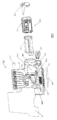
도 1은 일 실시예에 따른, 테스트 카트리지 시스템의 모식도를 도시한다.
도 2a - 도 2d는 일 실시예에 따른, 테스트 카트리지 시스템의 다양한 도면을 도시한다.
도 3a - 도 3d는 일 실시예에 따른, 전달 모듈의 내측 하우징의 다양한 도면을 도시한다.
도 4a - 도 4c는 일 실시예에 따른, 전달 모듈의 재킷의 3개의 도면을 도시한다.
도 5a 및 도 5b는 일 실시예에 따른, 테스트 카트리지 시스템의 모식도를 도시한다.
도 6a 및 도 6b는 일 실시예에 따른, 테스트 카트리지 시스템의 다양한 도면을 도시한다.
도 7a - 도 7f는 일 실시예에 따른, 전달 모듈의 다양한 도면을 도시한다.
도 8a 및 도 8b는 몇몇 실시예에 따른, 테스트 카트리지 시스템 내의 스왑을 도시한다.
도 9는 일 실시예에 따른, 테스트 카트리지 시스템에 의해 수행되는 방법을 도시하는 선도이다.
도 10은 일 실시예에 따른, 테스트 카트리지 시스템에 의해 수행되는 방법을 도시하는 선도이다.1 shows a schematic diagram of a test cartridge system, according to one embodiment.
2A-2D show various views of a test cartridge system, according to one embodiment.
3A-3D show various views of the inner housing of the delivery module, according to one embodiment.
4A-4C show three views of a jacket of a delivery module, according to one embodiment.
5A and 5B show schematic diagrams of a test cartridge system, according to one embodiment.
6A and 6B show various views of a test cartridge system, according to one embodiment.
7A-7F illustrate various views of a delivery module, according to one embodiment.
8A and 8B illustrate swap in a test cartridge system, in accordance with some embodiments.
9 is a diagram illustrating a method performed by a test cartridge system, according to one embodiment.
10 is a diagram illustrating a method performed by a test cartridge system, according to one embodiment.
본 발명의 실시예들이 첨부된 도면을 참조하여 설명될 것이다.Embodiments of the present invention will be described with reference to the accompanying drawings.
특정 구성 및 배열이 설명되지만, 이는 단지 예시적인 목적으로 이루어짐을 이해하여야 한다. 관련 기술 분야의 당업자는 다른 구성 및 배열이 본 발명의 사상 및 범주로부터 벗어남이 없이 사용될 수 있음을 인식할 것이다. 본 발명은 또한 다양한 다른 용도에서 채용될 수 있음이 관련 기술 분야의 당업자에게 명백할 것이다.While specific configurations and arrangements are described, it should be understood that this is for illustrative purposes only. Those skilled in the relevant art will recognize that other configurations and arrangements may be used without departing from the spirit and scope of the invention. It will be apparent to those skilled in the art that the present invention may also be employed in a variety of other applications.
명세서에서의 "하나의 실시예", "일 실시예", "예시적인 실시예" 등에 대한 참조는 설명되는 실시예가 특정 특징, 구조, 또는 특성을 포함할 수 있음을 표시하지만, 모든 실시예가 특정 특징, 구조, 또는 특성을 반드시 포함하지는 않을 수 있음을 알아야 한다. 또한, 그러한 문구는 동일한 실시예를 반드시 지칭하지는 않는다. 아울러, 특정 특징, 구조, 또는 특성이 일 실시예와 관련하여 설명될 때, 그러한 특징, 구조, 또는 특성을 명확하게 설명되는지의 여부와 관계없이 다른 실시예와 관련하여 달성하는 것이 본 기술 분야의 당업자의 지식 내에 있다.Reference to "one embodiment", "one embodiment", "exemplary embodiment", etc., in the specification indicates that the described embodiments may include particular features, structures, or characteristics, but not all embodiments are specific. It should be understood that the feature, structure, or characteristic may not necessarily be included. Moreover, such phrases are not necessarily referring to the same embodiment. In addition, when a particular feature, structure, or characteristic is described in connection with one embodiment, it is one of the skill in the art to achieve that, regardless of whether such feature, structure, or characteristic is clearly described. It is within the knowledge of those skilled in the art.
본원에서 설명되는 실시예들은 다양한 분자, 면역 검정, 또는 생화학적 테스트 등을 수행하기 위한 테스트 카트리지 시스템에 관한 것이다. 일 실시예에서, 테스트 카트리지는 그러한 테스트를 수행하기 위해 필요한 구성요소들 전부를 하나의 1회용 포장 내로 통합한다. 테스트 카트리지는 테스트 카트리지 내에서 발생하는 반응에 관련된 데이터를 제공하는 외부 측정 시스템에 의해 분석되도록 구성될 수 있다.Embodiments described herein relate to test cartridge systems for performing various molecules, immunoassays, biochemical tests, and the like. In one embodiment, the test cartridge integrates all of the components needed to perform such a test into one disposable package. The test cartridge may be configured to be analyzed by an external measurement system that provides data relating to the reactions occurring within the test cartridge.
하나의 예에서, 단일 테스트 카트리지가 주어진 샘플에서 다중화 면역 검정을 수행하기 위해 사용될 수 있다. 테스트 카트리지는 면역 검정을 수행하기 위해 카트리지 내로 통합된 밀봉된 챔버 내에 유지되는 필요한 완충제, 시약, 및 라벨 전부를 포함한다.In one example, a single test cartridge can be used to perform a multiplexed immunoassay on a given sample. The test cartridge contains all of the necessary buffers, reagents, and labels maintained in a sealed chamber integrated into the cartridge to perform an immunoassay.
다른 예에서, 단일 테스트 카트리지가 PCR을 수행하기 위해 사용될 수 있다. DNA 및/또는 RNA는 테스트 카트리지 내로 통합된 박막을 거쳐 샘플의 나머지(용해물)로부터 정제될 수 있다. 샘플은 박막을 통해 압출될 수 있고, 이때 분리되어 보관된 용출 액체가 DNA 및/또는 RNA를 제거하여 이를 온도 사이클링의 과정을 시작하기 위해 다른 챔버 내로 보낼 수 있다.In another example, a single test cartridge can be used to perform PCR. DNA and / or RNA can be purified from the remainder of the sample (lysate) via a thin film integrated into the test cartridge. The sample can be extruded through a thin film where the separated and stored elution liquid can be sent to another chamber to remove DNA and / or RNA and begin the process of temperature cycling.
위에서 설명된 것과 같은 임의의 테스트는 일정 형태의 액체 운반이 발생할 것을 요구한다. 일 실시예에서, 테스트 카트리지는 카트리지 하우징의 측면을 따른 포트에 정렬되는 복수의 포트를 포함하는 이동 가능한 중공 전달 모듈을 포함한다. 액체가 시스템에 압력차를 인가함으로써, 카트리지 하우징의 다른 다양한 챔버들 사이에서 중공 전달 모듈 내로 또는 그의 외부로 전달될 수 있다. 하나의 예에서, 외부 액추에이터가 압력차를 인가하기 위해 이용된다.Any test as described above requires some form of liquid delivery to occur. In one embodiment, the test cartridge includes a movable hollow delivery module that includes a plurality of ports aligned with the ports along the sides of the cartridge housing. By applying a pressure differential to the system, liquid can be delivered into or out of the hollow delivery module between the various other chambers of the cartridge housing. In one example, an external actuator is used to apply a pressure difference.
분자 진단 기기의 주요 제한들 중 하나는 교차 오염, 이월 오염 등과 같은 오염과 관련된 문제이다. 본원에서 설명되는 실시예들은 기구에 대한 샘플의 오염을 설계에 의해 실질적으로 제거한다.One of the major limitations of molecular diagnostic devices is the problem associated with contamination such as cross contamination, carryover contamination and the like. The embodiments described herein substantially eliminate contamination of the sample by design.
하나의 실시예에서, 테스트 카트리지는 제조 공정 중에 밀봉되는 자납식 액체를 제공한다. 시약 또는 샘플은 환경 또는 기구의 임의의 부분과 접촉하며 진입하지 않는다. 테스트 카트리지의 이러한 특징은 또한 제품을 그의 사용 후에 안전하게 폐기하기 위한 많은 실험실 및 병원에 대해 중요하다.In one embodiment, the test cartridge provides a self-supporting liquid that is sealed during the manufacturing process. The reagent or sample is not in contact with any part of the environment or instrument. This feature of the test cartridge is also important for many laboratories and hospitals for safely disposing of the product after its use.
테스트 카트리지 시스템의 구성요소에 관련된 추가의 세부는 도면을 참조하여 본원에서 설명된다. 각각의 물리적 구성요소의 예시는 제한적인 것으로 의미되지 않고, 관련 기술 분야(들)의 당업자는 본원의 설명이 주어지면, 본 발명의 범주 또는 사상으로부터 벗어남이 없이 임의의 구성요소를 재배열하거나 달리 변경하는 방식을 인식할 것임을 이해하여야 한다.Further details relating to the components of the test cartridge system are described herein with reference to the drawings. The illustration of each physical component is not meant to be limiting, and one of ordinary skill in the relevant art (s) should, given the description herein, rearrange or otherwise rearrange any component without departing from the scope or spirit of the invention. It is to be understood that the manner in which changes are made will be recognized.
제1 테스트 카트리지 실시예First Test Cartridge Embodiment
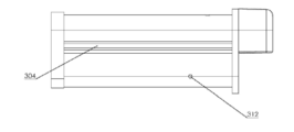
도 1 - 도 4는 일 실시예에 따른 테스트 카트리지 시스템의 다양한 도면 및 구성요소를 도시한다. 도 1은 카트리지 하우징(102) 및 전달 모듈(104)을 포함하는 테스트 카트리지 시스템(100)을 도시한다. 분석기 모듈 또는 펌프 또는 가열기와 같은 다양한 능동 구성요소와 같은 다른 구성요소도 테스트 카트리지 시스템(100) 내에 포함되도록 고려될 수 있다.1-4 illustrate various views and components of a test cartridge system according to one embodiment. 1 shows a
전달 모듈(104)은 내측 하우징(110), 재킷(108), 및 뚜껑(106)을 포함한다. 재킷(108)은 일 실시예에 따르면, 내측 하우징(110) 둘레에 끼워지도록 설계된다. 하나의 예에서, 내측 하우징(110)은 금속 또는 플라스틱과 같은 경질 재료로 만들어지고, 재킷(108)은 고무 또는 연질 플라스틱과 같은 순응성 재료로 만들어진다. 다른 예에서, 재킷(108) 및 내측 하우징(110) 모두가 동일한 재료이거나 상이한 재료일 수 있는 연질의 순응성 재료로 만들어진다. 다른 예에서, 재킷(108) 및 내측 하우징(110) 모두가 사출 공정을 거쳐 만들어진다. 뚜껑(106)은 누출을 방지하기 위해 전달 모듈(104)의 단부를 밀봉하도록 설계된다. 전달 모듈(104)의 구성요소에 관한 추가의 세부는 도 3 및 도 4를 참조하여 이후에 설명된다.The
전달 모듈(104)은 챔버 베이(120)를 거쳐 카트리지 하우징(102) 내로 삽입되도록 설계된다. 하나의 실시예에서, 전달 모듈(104)은 외부 액추에이터(도시되지 않음)에 연결되도록 구성된다. 외부 액추에이터는 전달 모듈(104) 상의 포트를 카트리지 하우징(102) 상의 포트에 정렬시키기 위해 카트리지 하우징(102) 내에서 전달 모듈(104)을 측방향으로 이동시킬 수 있다. 다른 실시예에서, 전달 모듈(104)은 사용자에 의한 외부 슬라이더의 작동을 거쳐 카트리지 하우징(102) 내에서 이동하도록 구성된다.The
카트리지 하우징(102)은 다양한 유체 채널, 챔버, 및 저장소를 포함한다. 예를 들어, 카트리지 하우징(102)은 검정 또는 PCR 프로토콜 중에 사용되는 다양한 완충제 또는 다른 시약을 담을 수 있는 복수의 보관 챔버(116)를 포함할 수 있다. 보관 챔버(116)는 최종 사용자가 분석기 내로 테스트 카트리지 시스템(100)을 위치시키기 전에 보관 챔버(116)를 충전할 필요가 없도록, 다양한 액체로 미리 충전될 수 있다. 카트리지 하우징(102)은 카트리지 하우징(102)의 일 측면을 따른 유체 채널에 연결된 하나 이상의 처리 챔버(124A - 124C)를 추가로 포함할 수 있다. 처리 챔버(124A - 124C)는 다양한 처리 및/또는 폐기물 용도를 위해 사용될 수 있다. 하나의 예에서, 챔버(124A)는 폐기물 챔버이고, 챔버(124B)는 PCR 프로토콜을 위한 용출 챔버이고, 챔버(124C)는 스왑 용출 챔버이다. 일 실시예에서, 카트리지 하우징(102)은 테스트 카트리지 시스템(100)의 더 용이한 취급을 제공하기 위한 파지 구조물(117)을 포함한다.
일 실시예에 따르면, 샘플이 샘플 포트(114)를 거쳐 카트리지 하우징(102) 내로 도입된다. 하나의 예에서, 샘플 포트(114)는 일반적인 의료용 스왑의 길이를 완전히 수납하도록 치수 설정된다. 따라서, 사용자는 스왑을 정지 지점까지 또는 샘플 포트(114) 내에 완전히 위치시키고, 이어서 포트 뚜껑(112)으로 포트를 밀봉할 수 있다. 다른 예에서, 샘플 포트(114)는 고체, 반고체, 또는 액체 샘플을 수납한다. 일 실시예에서, 카트리지 하우징(102)은 샘플을 도입하기 위한 하나를 초과하는 입구를 포함한다.According to one embodiment, the sample is introduced into the
카트리지 하우징(102)은 필터, 겔, 박막 등과 같은, 테스트를 수행하기 위한 하나 이상의 유용한 구조물을 포함할 수 있다. 예를 들어, 카트리지 하우징(102)은 공동(122) 내에 수용된 박막을 포함할 수 있다. 하나의 실시예에서, 박막은 카트리지 하우징(102)의 외부를 따른 유체 채널과 결합된다. 다른 실시예에서, 박막은 처리 챔버(124A - 124C)들 중 임의의 하나 내에 배치될 수 있다.
카트리지 하우징(102) 둘레의 다양한 챔버 및 채널이 커버(118, 126, 128)의 사용에 의해 밀봉될 수 있다. 커버는 카트리지 하우징(102) 내에 유체를 밀봉할 수 있는 필름일 수 있다. 다른 예에서, 커버는 플라스틱 시트 또는 임의의 다른 밀봉 수단일 수 있다. 하나의 예에서, 커버들 중 하나 이상이 투명하다.Various chambers and channels around the
통합 테스트 카트리지 시스템(100)은 사용자가 샘플을, 예를 들어, 샘플 포트(114) 내로 위치시킨 다음, 테스트 카트리지 시스템(100)을 분석기 내로 위치시키도록 허용한다. 실시예에서, 예를 들어, 재현탁 용해, 정제, 혼합, 가열, 결합, 라벨링, 및/또는 검출을 포함한, 수행되어야 하는 반응 단계들은 모두 최종 사용자가 개입할 임의의 필요가 없이 분석기와의 상호 작용을 거쳐 테스트 카트리지 시스템(100) 내에서 수행될 수 있다. 추가로, 모든 액체가 테스트 카트리지 시스템(100) 내에서 밀봉 유지되므로, 테스트가 완료된 후에, 테스트 카트리지 시스템(100)은 분석기로부터 제거되어 분석기의 오염이 없이 안전하게 폐기될 수 있다.The integrated
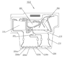
도 2a - 도 2d는 실시예에 따른, 카트리지 하우징(102)의 다양한 도면을 도시한다. 각각의 도면의 설명은 카트리지 하우징(102) 상에 존재할 수 있는 특징부를 설명하기 위해 기술되지만, 특징부들의 배치 또는 치수 특성에 관하여 제한적이지 않아야 한다.2A-2D show various views of the
도 2a는 카트리지 하우징(102)의 측면도의 하나의 예를 제공한다. 이와 같이, 도면은 유체 네트워크에 의해 연결된 복수의 챔버, 및 카트리지 하우징(102) 내로 연장하는 일련의 포트를 도시한다. 이러한 그룹들 각각은 본원에서 더 상세하게 설명될 것이다.2A provides one example of a side view of a
복수의 처리 챔버는 폐기물 챔버(218), 용출 챔버(220), 및 스왑 용출 챔버(206)를 포함할 수 있다. 본원의 설명이 주어지면 관련 기술 분야(들)의 당업자에 의해 고려되는 바와 같은 다른 유형의 챔버들이 또한 포함될 수 있다. 또한, 각각의 챔버의 목적은 본원에서 규정되는 명칭과 상이할 수 있다.The plurality of processing chambers may include a
복수의 반응 챔버(216)가 또한 도시되어 있다. 그러한 챔버들은, 예를 들어, 원심분리기 튜브와 유사하게 성형될 수 있다. 하나의 실시예에서, 액체가 반응 챔버(216)들 내로 흡인되어, 각각의 반응 챔버 내로 미리 장입된 시약과 혼합될 수 있다. 예를 들어, 각각의 반응 챔버는 상이한 DNA 프로브 또는 실시간 PCR 주혼합물로 장입될 수 있고, 액체가 각각의 챔버 내에서 별개의 혼합물을 생성하도록 각각의 반응 챔버 내로 흡인될 수 있다. 시약은 장입되기 전에 동결 건조될 수 있거나, 반응 챔버(216) 내에서 동결 건조될 수 있다. 다른 실시예에서, 반응 챔버(216)는 또한 샘플 검출을 위해 사용된다. 따라서, 하나의 실시예에서, 반응 챔버(216)는 또한 검출 챔버인 것으로 간주될 수 있다. 검출은 테스트 카트리지 시스템(100)이 위치되는 분석기에 결합된 외부 광원 및 광검출기를 사용하여 발생할 수 있다. 따라서, 반응 챔버(216)의 임의의 벽 또는 커버가 광학 검출을 허용하기 위해 투명할 수 있다. 하나의 예에서, 광검출기는 하나 이상의 파장에서 반응 챔버 내의 액체를 통한 흡수율을 측정한다. 다른 예에서, 광검출기는 반응 챔버 내의 형광 화합물로부터 발생되는 형광 신호를 측정한다. 일 실시예에서, 형광 측정은 반응 챔버(216) 아래로부터 취해진다. 반응 챔버(216)는 다른 검출 수단, 예컨대, 전기화학적, 전기기계적, 표면 플라즈몬 공명 등을 위해 구성될 수 있다.A plurality of
일 실시예에 따르면, 소형 채널 확대부(214)의 세트가 반응 챔버(216)로부터 상류에서 관찰된다. 채널 확대부(214)는 액체 감지 영역으로서 작용할 수 있다. 이와 같이, 채널 확대부(214)는 액체가 채널 확대부(214) 내에 존재하는지의 여부를 결정하기 위해 외부 광학 프로브와 함께 사용될 수 있다. 이러한 결정은 테스트 카트리지 시스템(100)의 다른 기능을 활성화하기 위해 사용될 수 있다. 다른 실시예에서, 채널 확대부(214)는 유체의 존재 또는 유량을 표시하기 위해, 패턴화된 저항식 센서와 같은 집적 센서를 포함할 수 있다.According to one embodiment, a set of
다양한 유체 채널이 각각의 챔버에 또는 카트리지 하우징(102) 내의 다른 요소에 연결된다. 각각의 채널은 또한 전달 모듈(104) 상의 포트 또는 밸브 영역과 접속하는 포트에서 종결하도록 설계된다. 일 실시예에서, 카트리지 하우징(102)은 액체 포트(210)의 열 및 통기/흡입 포트(212)의 열과 같은, 2개의 주요 포트의 열을 포함한다. 액체 포트(210)는 유체가 도 2a에 도시된 임의의 챔버로 유동하거나 필터(222)를 통해 유동하도록 허용한다. 액체 포트(210)는 액체가 카트리지 하우징(102)으로부터 전달 모듈(104) 내로 흡인되게 하기 위한 입구 포트로서, 또는 액체가 전달 모듈(104)로부터 카트리지 하우징(102)의 유체 네트워크로 방출되게 하기 위한 출구 포트로서, 작용할 수 있다. 통기/흡입 포트(212)는 액체가 그의 대응하는 챔버 내로 흡입될 수 있도록, 특정 유체 채널을 대기로 개방하기 위해 사용될 수 있다. 예를 들어, 진공 압력이 통기/흡입 포트(212)들의 열의 가장 좌측 상에 도시된 포트에 인가될 수 있고, 이는 액체가 액체 포트(210)들의 열 상의 좌측의 제2 포트를 거쳐 폐기물 챔버(218) 내로 진입하도록 허용한다. 다른 예에서, 통기/흡입 포트(212)들의 열 상의 좌측의 제2 포트로부터 인가되는 진공 압력이 액체를 좌측의 제3 액체 포트로부터 용출 챔버(220) 내로 흡인한다. 다른 실시예에서, 통기/흡입 포트(212)는 대기로 개방될 수 있다.Various fluid channels are connected to each chamber or to other elements within the
카트리지 하우징(102)의 다른 섹션 내로 이어지는 다른 처리 포트(204)가 관찰될 수 있다. 처리 포트(204)는 내측 처리 챔버 내로 또는 그의 외부로 이어질 수 있다. 예를 들어, 내측 처리 챔버는 샘플 내의 임의의 세포를 용해시키기 위한 비드 비터(bead beater) 챔버일 수 있다. 다른 예에서, 고체, 반고체, 또는 액체 물질을 함유하는 샘플이 제2 샘플 입구를 거쳐 내측 처리 챔버 내로 직접 위치될 수 있다. 물질은 내측 처리 챔버에 의해 균질화되거나 용해될 수 있고, 결과적인 액체 샘플은 내측 처리 챔버의 내측 포트(도시되지 않음)를 거쳐 내측 처리 챔버로부터 전달 모듈(104)로 흡인될 수 있다.
포트가 카트리지 하우징(102)의 두께를 통해 연장하는 작은 구멍일 수 있다. 일 실시예에서, 액체 포트(210)들 각각은 다양한 액체 포트(210)들 사이에서 측방향으로 이동할 수 있는 전달 모듈(104) 상에 위치된 다른 포트에 정렬되도록 설계된다. 일 실시예에서, 통기/흡입 포트(212)들 각각은 포트가 대기로 통기되거나 가압되도록 허용하는 전달 모듈(104) 둘레의 영역에 정렬되도록 설계된다. 다양한 포트들은 임의의 인가되는 압력의 부재 시에 포트를 통한 누출을 방지하기 위해, 소수성 재료를 포함할 수 있거나 특정 기하학적 구성을 가질 수 있다.The port may be a small hole extending through the thickness of the
필터(222)가 도시된 바와 같이 유체 네트워크 내에 통합될 수 있다. 이와 같이, 액체가 압력차로 인해 필터(222)를 통해 통과할 수 있다. 필터(222)는, 예를 들어, 핵산 서열을 포착하기 위해 사용되는 실리케이트 매트릭스를 포함할 수 있다. 다른 예에서, 필터(222)는 전혈 샘플로부터 혈장을 추출하기 위한 박막일 수 있다. 역삼투압 필터와 같은 다른 필터 유형도 고려될 수 있다. 다른 예에서, 필터(222)는, 예를 들어, 단백질 정제 프로토콜을 수행하기 위한 친화성 크로마토그래피 칼럼에 대해 적합한 재료를 포함할 수 있다.
도 2b는 카트리지 하우징(102)의 다른 예시적인 실시예를 도시한다. 이러한 실시예는 폐기물 챔버(218), 용출 챔버(220), 및 스왑 용출 챔버(206)를 포함하는 도 2a에 도시된 예시적인 카트리지 하우징과 동일한 많은 특징을 포함한다. 그러나, 액체 포트(210)에 연결된 유체 네트워크는 이제 반응 챔버(224), 챔버(225), 및 복수의 검출 챔버(226a - 226e)를 포함한다. 하나의 예에서, 단일 유체 경로가 반응 챔버(224), 챔버(225), 및 검출 챔버(226a - 226e) 각각을 함께 연결한다. 다른 예에서, 유체 경로는 폐기물 챔버(218)에서 종결한다. 일련의 채널 확대부(214)들이 또한 도시되어 있고, 도 2a에서 위에서 설명된 실시예의 것과 동일한 목적을 이룰 수 있다. 이러한 실시예에서 설명되는 챔버들의 배열은 면역 검정 또는 다른 유형의 결합 친화성 검정에 대해 유용할 수 있다.2B shows another exemplary embodiment of a
반응 챔버(224)는 검출 챔버(226a - 226e) 상으로 통과하기 전에 샘플과 혼합되는 시약을 담을 수 있다. 시약은 먼저 동결 건조되어 반응 챔버(224) 내로 위치되거나, 반응 챔버 내에서 동결 건조되어, 액체 샘플과 접촉 시에 재수화될 수 있다. 챔버(225)는 동결 건조된 시약의 새로운 세트를 담을 수 있고, 핵산 서열의 추가의 증폭을 수행하기 위한 PCR 프로토콜 중에 이용될 수 있다. 다른 예에서, 챔버(225)는 샘플과 혼합되는 추가의 시약을 담을 수 있다. 대안적으로, 챔버(225)는 샘플이 검출 챔버(226a - 226e) 상으로 통과하기 전에, 샘플로부터 소정의 화합물을 분리하기 위한 필터 또는 포획 프로브를 포함할 수 있다.The
검출 챔버(226a - 226e)는 도 2a에서 위에서 설명된 바와 같은 반응 챔버(216)와 유사하게 광학적 호출을 허용하도록 구성된다. 하나의 예에서, 각각의 검출 챔버(226a - 226e)는 다양한 결합 친화성 검정을 수행하기 위한 고정 프로브를 포함한다. 검출 챔버(226a - 226e)의 적어도 하나의 벽이 형광 측정을 위한 가시광에 대해 투명하게 만들어진다. 하나의 예에서, 형광 측정은 검출 챔버(226a - 226e) 아래로부터 취해진다.
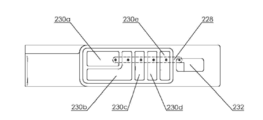
도 2c는 일 실시예에 따른, 카트리지 하우징(102)의 평면도를 도시한다. 복수의 보관 챔버(230A - 230E)가 관찰되고, 도 1에서 이전에 설명된 바와 같은 보관 챔버(116)와 유사할 수 있다. 샘플 입구 창(232)이 또한 일 실시예에 따르면, 카트리지 하우징(102)의 상부에 배치된다. 샘플 입구 창(232)은 내측 처리 챔버 내로 샘플을 위치시키기 위해 사용될 수 있다. 예를 들어, 고체 샘플은 시험이 시작할 수 있기 전에 균질화될 필요가 있을 수 있다. 이러한 고체 샘플은 샘플 입구 창(232) 내로 위치되어, 내측 처리 챔버 내로 직접 진입할 수 있다.2C shows a top view of a
입구 포트(228)들의 열이 일 실시예에 따르면, 각각의 포트가 고유한 보관 챔버 내에 놓이도록 제공된다. 다양한 보관 챔버(230A - 230E) 내에 보관된 용액은 시험 절차 중에 적절한 시점에서 대응하는 입구 포트를 통해 전달 모듈(104) 내로 흡인될 수 있다. 따라서, 전달 모듈(104)은 또한 입구 포트(228)들 각각과 정렬될 수 있는 전달 모듈(104)의 상부에 위치된 다른 포트를 갖는다. 하나의 예에서, 전달 모듈(104)의 측방향 이동은 입구 포트(228)들 중 어떤 포트가 전달 모듈(104)의 상부 포트에 정렬되는지를 변화시킨다. 다른 예에서, 입구 포트(228)는 전달 모듈(104)에 도달하기 전에 카트리지 하우징(102) 내의 유체 네트워크로 직접 이어질 수 있다.A row of
보관 챔버(230A - 230E)들 중 적어도 하나가 샘플 포트(114)를 거쳐 카트리지 하우징(102) 내로 위치된 샘플을 수납하도록 구성될 수 있다. 예를 들어, 보관 챔버(230B)는 샘플 면봉을 수납하도록 치수 설정될 수 있다. 다른 예에서, 보관 챔버(230B)는 샘플이 도입되면 샘플을 현탁하기 위한 용액을 담는다.At least one of the storage chambers 230A-230E may be configured to receive a sample located into the
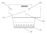
도 2d는 (도 2a에 도시된 측면으로부터 대향하는) 카트리지 하우징(102)의 다른 측면의 도면을 도시한다. 추가로, 카트리지 하우징(102)은 일 실시예에 따르면, 가압 포트(236) 및 통기 포트(234)를 포함한다. 가압 포트(236)는 외부 압력 공급원, 예컨대, 진공 펌프, 시린지 펌프, 압력 펌프 등에 연결될 수 있다. 하나의 예에서, 외부 압력 공급원은 테스트 카트리지 시스템(100)이 위치되는 분석기와 통합된다. 가압 포트(236)를 거쳐 시스템에 인가되는 압력차는 카트리지 하우징(102) 및 전달 모듈(104) 내의 다양한 영역 전반에 걸쳐 액체를 운반하기 위해 사용될 수 있다. 통기 포트(234)는 일 실시예에 따르면, 대기로 개방되도록 구성될 수 있다. 이와 같이, 통기/흡입 포트(212)는 통기 포트(234)에 또한 결합되는 전달 모듈(104) 둘레의 영역으로 이어질 수 있다. 다른 예에서, 가압 공급원이 통기/흡입 포트(212)를 통해 액체를 당기기 위해 가압 포트(236)에 연결된다. 임의의 개수의 포트가 카트리지 하우징(102) 및 전달 모듈(104) 내의 그리고 그 둘레의 다양한 영역을 가압할 목적으로 포함될 수 있다.FIG. 2D shows a view of another side of the cartridge housing 102 (opposite from the side shown in FIG. 2A). Additionally,
하나의 실시예에서, 카트리지 하우징(102)은 자동화된 분석기 내에서 테스트 카트리지 시스템(100)을 중심 설정하도록 구성된 구조를 제공한다. 예를 들어, 복수의 오리피스(235a - 235b)가 외부 정밀 위치 설정 시스템에 관하여 테스트 카트리지 시스템(100)을 중심 설정하는 것을 보조하기 위해 분석기 상의 대응하는 핀과 결합하도록 카트리지 하우징(102) 상에 존재할 수 있다. 장방형 돌출부가 자동화된 분석기 내에서 테스트 카트리지 시스템(100)을 중심 설정하기 위해 또한 사용될 수 있다. 도 2d의 카트리지 하우징(102)의 하부 부분에, 광학 접근 영역(240)이 일 실시예에 따르면, 반응 챔버(216) 아래에 배치된다. 광학 접근 영역(240)은 광학 검출 과정 중에 사용되는 모든 파장에 대해 실질적으로 투명하도록 구성된다. 하나의 예에서, 각각의 개별 반응 챔버는 그 자신의 광학 접근 영역을 갖는다. 다른 예에서, 단일 광학 접근 영역이 복수의 반응 챔버(216)를 가로질러 걸친다.In one embodiment, the
하나의 필름 또는 복수의 필름이 일련의 반응 챔버(216) 위에 위치될 수 있다. 필름은 적절한 밀봉을 여전히 제공하기에 충분히 얇을 수 있으며, 또한 외부 공급원에 의한 반응 챔버(216) 내의 내용물의 더 용이한 가열 및/또는 냉각을 허용할 수 있다. 예를 들어, 필름은 열전 장치, 저항식 가열기, 및 강제 순환 공기 중 임의의 하나 또는 이들의 조합에 의해 열적으로 제어되는 표면과 접촉할 수 있다.One film or a plurality of films may be positioned above the series of
도 3a - 도 3d는 일 실시예에 따른, 전달 모듈(104)의 내측 하우징(110) 둘레 및 내부의 다양한 도면을 도시한다. 도 3a는 일 실시예에 따른, 내측 하우징(110)의 사시도를 도시한다. 내측 하우징(110)은 강성 재료일 수 있는 케이스(302)로부터 형성된다. 예를 들어, 케이스(302)는 경질 플라스틱 또는 금속 재료일 수 있다. 다른 예에서, 케이스(302)는 가요성 플라스틱 재료일 수 있다.3A-3D show various views around and inside the
내측 하우징(110)은 케이스(302)의 두께를 통해 연장하는 하나 이상의 포트를 포함한다. 포트는 1차 입구 포트(306) 및 전달 압력 포트(308)를 포함할 수 있다. 일 실시예에서, 1차 입구 포트(306)는 도 2c에 도시된 바와 같이 입구 포트(228)들 중 다양한 것들과 정렬된다.
일 실시예에서, 트랙(304)이 밸브 재킷(108)을 내측 하우징(110) 둘레에서 제 위치에 유지하기 위해 사용된다. 밸브 재킷(108)은 도 4a - 도 4c에서 분리되어 설명될 것이다. 케이스(302)는 또한 전달 모듈(104)을 액추에이터에 연결하기 위한 결합 영역(310)을 포함할 수 있다. 액추에이터는 가동되어, 전달 모듈(104) 상에 힘을 인가하여 이동을 일으킬 수 있다. 다른 실시예에서, 결합 영역(310)은 사용자가 구조물에 힘을 인가하여 결과적으로 전달 모듈(104)을 이동시키도록 허용하는 임의의 방식의 구조물에 연결될 수 있다.In one embodiment, a
도 3b는 내측 하우징(110)의 측면도를 도시한다. 도시된 도면은 도 3a에서 멀리 향하는 측면이다. 유사한 트랙(304)이 또한 내측 하우징(110)의 이러한 측면 상에 도시되어 있다. 다른 실시예에서, 내측 하우징(110)은 단일 트랙 구조물만을 포함한다. 또한, 1차 출구 포트(312)가 도시되어 있다. 일 실시예에서, 1차 출구 포트(312)는 도 2a에 도시된 바와 같이 액체 포트(210)들 중 다양한 것들과 정렬된다. 내측 하우징(110)은 케이스(302)의 표면 둘레에서 임의의 개수의 포트를 포함할 수 있고, 본원에서 도시된 도면들은 그들의 배치 및 포트의 개수에 있어서 제한적인 것으로 의미되지 않음을 이해하여야 한다.3B shows a side view of the
도 3c는 일 실시예에 따른, 내측 하우징(110)의 내부의 단면도를 도시한다. 케이스(302)는 전달 챔버(316)를 에워싼다. 또한, 유체 또는 임의의 다른 샘플 유형을 전달 챔버(316) 내에 밀봉하기 위한 챔버 커버(318)가 포함된다.3C shows a cross-sectional view of the interior of the
1차 출구 포트(312)는 전달 챔버(316) 내의 최저 지점에 또는 그 부근에 도시되어 있다. 배치는 전달 챔버(316) 내의 임의의 액체가 1차 출구 포트(312)를 통해 적절하게 배출되도록 허용한다. 적절한 배출을 더욱 용이하게 하기 위해, 전달 챔버(316)의 내벽은 일 실시예에 따르면, 하방으로 경사진다. 하나의 예에서, 전달 챔버(316)의 하나 이상의 벽이 경사진다. 하나의 예에서, 쐐기(320)가 경사 표면을 제공하기 위해 전달 챔버(316) 내에 배치된다.
일 실시예에서, 전달 챔버(316)는 교반 요소(324)를 포함한다. 예를 들어, 교반 요소(324)는 자석 교반 막대일 수 있다. 교반 요소(324)는 전달 챔버(316)의 내용물을 효과적으로 혼합하기 위해 사용될 수 있다. 하나의 예에서, 교반 요소(324)는 외부 자기장을 거쳐 여기된다. 일 실시예에서, 카트리지 하우징(102)은 전달 모듈(104)의 이동 경로를 따라 배치된 하나 이상의 자석을 포함한다. 자석의 존재는 교반 요소(324) 상에서 자력을 유도하여, 교반 요소가 전달 챔버(316) 내에서 이동하게 할 수 있다. 다른 예에서, 교반 요소(324)는 교반 요소(324)를 이동시키도록 구성된 액추에이터에 물리적으로 결합된다.In one embodiment, the
도 3d는 일 실시예에 따른, 뚜껑(106)의 사시도를 도시한다. 뚜껑(106)은 챔버 커버(318) 및 챔버 커버(318)에 결합된 쐐기(320)를 포함할 수 있다. 쐐기(320)의 챔버 커버(318)와의 통합은 더 용이한 제조 공정을 허용한다.3D shows a perspective view of the
도 3a로 돌아가면, 내측 하우징(110) 둘레에 배치된 다양한 포트가 카트리지 하우징(102)의 다양한 챔버들과 전달 챔버(316) 사이에서 액체를 전달하기 위해 이용될 수 있다. 예시적인 공정에서, 전달 모듈(104)은 1차 입구 포트(306)를 카트리지 하우징(102)의 복수의 내측 포트(228)들 중 하나와 정렬시키기 위해 측방향으로 이동된다. 정렬되면, 진공 압력이 전달 압력 포트(308)를 거쳐 인가될 수 있고, 이는 액체를 카트리지 하우징(102)의 보관 챔버로부터 전달 모듈(104)의 전달 챔버(316) 내로 흡인할 것이다. 전달 모듈(104)의 추가의 측방향 이동은 1차 입구 포트(306)를 카트리지 하우징(102)의 복수의 입구 포트(228)들 중 상이한 하나와 정렬시킨다. 제2의 인가되는 진공 압력이 액체를 카트리지 하우징(102)의 다른 보관 챔버로부터 전달 챔버(316) 내로 흡인한다. 전달 챔버(316) 내의 2개의 액체는 필요하다면 교반 요소(324)에 의해 더욱 혼합될 수 있다. 전달 모듈(104)의 제3 측방향 이동은 1차 출구 포트(312)를 카트리지 하우징(102)의 액체 포트(210)들 중 하나와 정렬시킨다. 전달 압력 포트(308)에 인가되는 양압이 액체를 전달 챔 버(316)로부터 1차 출구 포트(312)를 통해, 정렬된 액체 출구 포트를 거쳐 카트리지 하우징(102)의 유체 네트워크 내로 방출한다. 더 많은 액체 흡인 및 방출 절차가 수행될 수 있고, 액체는 또한 1차 출구 포트(312)를 거쳐 전달 챔버(316) 내로 흡인될 수 있음을 이해하여야 한다.Returning to FIG. 3A, various ports disposed around the
특정 유체 채널을 따른 유체 유동을 제어하고, 전달 모듈(104)의 외부 둘레의 어떤 영역이 가압되는지를 제어하기 위해, 밸브 시스템이 내측 하우징(110) 둘레에서 구현된다. 도 4a - 도 4c는 내측 하우징(110) 둘레에 배치된 밸브 재킷(108)의 다양한 도면을 도시한다.A valve system is implemented around the
도 4a는 일 실시예에 따른, 밸브 재킷(108)의 사시도를 도시한다. 밸브 재킷(108)은 내측 하우징(110) 둘레에 끼워지는 순응성 케이싱(402)을 포함한다. 순응성 케이싱(402)은 고무와 같은 가요성 재료일 수 있다. 일 실시예에서, 순응성 케이싱(402)의 외측 표면은 순응성 케이싱(402)의 두께를 통해 연장하며 내측 하우징(110) 상의 포트와 정렬되는 포트를 포함한다. 예를 들어, 제1 포트(410)가 1차 출구 포트(312)와 정렬될 수 있고, 제2 포트(412)가 1차 입구 포트(306)와 정렬될 수 있다.4A shows a perspective view of a
순응성 케이싱(402)의 외측 표면은 또한 일 실시예에 따르면, 다양한 패턴화된 리지 및 형상을 포함할 수 있다. 예를 들어, 밸브 재킷(108)의 측면을 따른 환상 리지(404)가 복수의 통기/흡입 포트(212)들 중 다양한 것들과 정렬될 수 있다. 추가의 환상 구조물(414)이 밸브 재킷(108)의 상부를 따라 관찰된다. 중실 환상 구조물(414)은 각각의 포트를 원치 않게 가압되는 것으로부터 보호하기 위해 복수의 입구 포트(228)들 중 다양한 것들 위에 정렬될 수 있다. 중실 환상 구조물(414)은 보관 챔버(230a - 230e) 내에서의 장기간 액체 보관에 대해 바람직하다. 중공 환상 형상이 전달 모듈(104)이 카트리지 하우징(102) 내에서 이동할 때 마찰을 감소시키는 이점을 제공한다.The outer surface of the
다른 패턴화된 리지가 또한 존재할 수 있다. 예를 들어, 가리비형 리지(406)가 제1 포트(410)와 정렬되지 않은 임의의 복수의 액체 포트(210)를 밀봉하기 위해 밸브 재킷(108)의 길이를 따라 연장할 수 있다. 다른 예에서, 직선 리지(408)가 카트리지 하우징(102)의 내측 표면 상에서의 균질 압력을 보장한다.Other patterned ridges may also be present. For example, the
다양한 리지 패턴은 카트리지 하우징(102)의 내벽에 대해 가압하도록 설계된다. 이는 서로로부터 밀봉되는 전달 모듈(104)의 외측 표면 둘레의 복수의 영역을 생성한다. 따라서, 하나의 영역 내의 인가되는 압력차는 다른 영역 내의 압력에 영향을 주지 않을 것이다. 이러한 예시적인 설계는 도 4b에서 더 명확하게 관찰될 수 있다.The various ridge patterns are designed to press against the inner wall of the
도 4b는 일 실시예에 따른, 전달 챔버(102) 내의 전달 모듈(104)의 단면을 도시한다. 전달 모듈(104)의 내측 하우징(302) 및 밸브 재킷(108)이 도시되어 있고, 아울러 밸브 재킷(108)의 돌출부(416)가 도시되어 있다. 돌출부(416)는 도 4a를 참조하여 이전에 설명된 바와 같은 리지 및 환상 형상과 유사할 수 있다. 돌출부(416)는 일 실시예에 따르면, 영역(418A - 418C)과 같은, 복수의 밸브 영역을 생성하기 위해 카트리지 하우징(102)의 내벽에 대해 가압된다. 예를 들어, 영역(418B)은 돌출부(416)로 인해 영역(418A, 418C)으로부터 분리되고, 이와 같이, 영역(418A, 418C)으로부터 분리되어 가압될 수 있다.4B shows a cross section of the
하나의 예에서, 영역(418B)은 카트리지 하우징(102)의 일 측면 상의 가압 포트(236)(도 2d)와 관련된다. 가압 포트(236)(도 2d)를 거쳐 인가되는 압력차는 또한 돌출부(416)에 의해 분리된 주위 영역들을 가압하지 않고서, 영역(418B)을 가압할 것이다.In one example,
단면도는 또한 전달 모듈(104)의 제1 포트(410)가 어떻게 카트리지 하우징(102)의 액체 포트(210)들 중 하나와 정렬될 수 있는지를 도시한다. 돌출부(416)는 유체의 누출 또는 포트 영역의 원치 않는 가압을 방지하기 위해 포트(410)를 둘러쌀 수 있다.The cross-sectional view also shows how the
도 4c는 일 실시예에 따른, 밸브 재킷(108)의 측면도를 도시한다. 도시된 측면도는 도 4a에서 멀리 향하는 측면이다. 밸브 재킷(108)은 일 실시예에 따르면, 내측 하우징(110)의 전달 압력 포트(308)와 정렬될 수 있는 압력 포트(420)를 추가로 포함한다. 압력 포트(420)는 직선 리지(428) 및 사행 리지(422)와 같은 다양한 리지에 의해 형성된 가압 영역(424) 내에 배치된다. 리지의 패턴 및/또는 형상은 도시된 것으로 제한되지 않는다. 다른 영역(426)이 일 실시예에 따르면, 사행 리지(422)의 다른 측면 상에 존재한다. 도 4c를 참조하여 설명된 영역은 도 4b를 참조하여 위에서 설명된 영역과 유사한 것으로 고려될 수 있다.4C shows a side view of the
가압 영역(424)은 일 실시예에 따르면, 카트리지 하우징(102)의 포트와 관련된다. 예를 들어, 전달 모듈(104)이 카트리지 하우징(102) 내에 위치되었을 때, 가압 포트(236)는 가압 영역(424) 내에 위치될 수 있다. 하나의 예에서, 가압 포트는 사행 리지(422)의 중간 수평 부분 아래에 위치된다. 전달 모듈(104)이 카트리지 하우징(102) 내에서 병진 이동할 때, 가압 영역(424)은 하나의 예에 따르면, 가압 포트(236)와 관련되어 유지된다. 다른 예에서, 전달 모듈(104)의 병진 이동은 사행 리지(422)와 관련된 사행 형상으로 인해, 통기 포트(234)를 가압 영역(424) 내에 그리고 가압 포트(236)를 영역(426) 내에 정렬시킬 수 있다. 가압 영역(424) 내에 정렬된 포트를 거쳐 인가되는 압력차는 또한 압력 포트(420)를 거쳐 전달 챔버(316) 내에 동일한 압력차를 인가할 것이다. 다른 예에서, 전달 모듈(104)의 병진 이동은 가압 포트(236)를 밸브 재킷(108)의 외부 표면 둘레의 다양한 영역과 정렬시킨다.The
영역(426)은 또한 일 실시예에 따르면, 카트리지 하우징(102)의 포트와 관련된다. 예를 들어, 통기 포트(234)가 사행 리지(422)의 중간 수평 부분 바로 위와 같은, 영역(426) 내에 위치될 수 있다. 이러한 예에서, 영역(426)은 대기압으로 개방된다. 대안적으로, 가압 포트(236)가, 예를 들어, 사행 리지(422)의 굽힘부 사이에서, 영역(426) 내에 위치될 수 있다. 진공 압력이 가압 포트(236)에 인가될 수 있고, 이는 유사하게 영역(426)을 가압한다.
영역(426)은 일 실시예에 따르면, 밸브 재킷(108)의 다른 측면(도 4a에 도시된 측면)에 감길 수 있다. 따라서, 환상 리지(404)를 둘러싸는 영역 및 환상 구조물(414)은 모두 영역(426)과 동일한 영역으로 간주될 수 있다. 예시적인 실시예에서, 전달 모듈(104)이 별개의 단차들 사이에서 카트리지 하우징(102) 내에서 이동할 때, 환상 리지(404)는 일 실시예에 따르면, 통기/흡입 포트(212)들 중 하나를 제외한 전부를 덮는다. 환상 리지(404)에 의해 덮이지 않는 하나의 통기/흡입 포트는 그 다음 대기압 또는 영역(426)에 인가된 압력차를 받는다.
제2 테스트 카트리지 실시예Second Test Cartridge Embodiment
도 5 - 도 8은 다른 실시예에 따른 테스트 카트리지 시스템의 다양한 도면 및 구성요소를 도시한다. 도 5a - 도 5b는 카트리지 하우징(502) 및 전달 모듈(504)을 포함하는 테스트 카트리지 시스템(500)에 대한 단순화된 표현의 도면을 도시한다. 전달 모듈(504)은 제1 테스트 카트리지 실시예로부터의 전달 모듈(104)과 실질적으로 동일한 기능을 시스템 내에서 갖는다. 양 전달 모듈(504, 104)은 몇몇 실시예에 따르면, 전달 모듈의 외부 상의 포트를 하우징(502, 102)의 측면들 상의 포트와 정렬시키기 위해 시스템 내에서 측방향으로 이동한다. 또한, 전달 모듈(504)은 재킷(508)에 의해 둘러싸여서 뚜껑(506)에 의해 캡핑되는 내부 챔버를 갖는 내측 하우징(510)을 구비하여, 전달 모듈(104)과 유사한 구성을 갖는다. 전달 모듈(504)의 추가의 세부가 도 7a - 도 7d를 참조하여 이후에 설명된다.5-8 illustrate various views and components of a test cartridge system according to another embodiment. 5A-5B show a simplified representation of a
하우징(502)은 몇몇 실시예에 따르면, 하우징(102)과 많은 동일한 특징을 포함한다. 예를 들어, 하우징(502)은 복수의 처리 챔버(524a - 524b), 전달 모듈(504)을 수납하기 위한 챔버 베이(520), 및 포트 뚜껑(512)을 구비한 샘플 포트(514)를 포함한다. 하나의 예에서, 챔버(524a)는 폐기물 챔버이고, 챔버(524b)는 스왑 리셉터클 챔버이다. 샘플 포트(514)는 하나의 실시예에 따르면, 의료용 스왑의 길이를 수납하도록 치수 설정될 수 있는 챔버(524b) 내로 이어진다. 하우징(502)은 또한 일 실시예에 따르면, 하우징(502) 둘레의 다양한 챔버 및 채널을 밀봉하기 위한 다양한 커버(518, 526, 527, 528)를 포함한다. 하나의 예에서, 커버(526, 518)들 각각은 하우징(502)과 실질적으로 동일한 재료로부터 만들어진다. 일 실시예에서, 커버(526, 528, 518)들 중 임의의 하나가 실질적으로 투명하다. 커버(527)는 하우징(502) 내의 샘플로의 더 효율적인 열 전달을 허용하기 위해, 높은 열 전도율을 갖는 재료, 예컨대, 알루미늄 호일일 수 있다. 개방부(513)가 커버(526) 내로 절단될 수 있어서, 열이 커버(527)로부터 개방부(513)를 거쳐 하우징(502)의 내측 처리 챔버로 더 효율적으로 전도될 수 있다. 내측 처리 챔버는 또한 커버(532)를 구비한 그 자신의 입구를 가질 수 있다. 일 실시예에서, 하우징(502)은 하우징(502) 내로 위치되는 다양한 유형의 필터를 수납하기 위한 상부 개방부(522)를 포함한다. 하나의 예에서, 박막 또는 실리카 비드와 같은 고체상 추출 재료가 상부 개방부(522)를 거쳐 하우징(502)의 챔버 내로 위치될 수 있다. 복수의 개방부가 몇몇 실시예에 따르면, 커버(526, 527) 내에서 관찰된다. 커버(526)의 개방부는, 예를 들어, 건조 시약을 위한 더 많은 공간이 작은 챔버 내로 위치되도록 허용하기 위해, 하우징(502)의 다양한 소형 챔버들 위에 정렬될 수 있다. 다른 예에서, 커버(527)의 개방부는 하우징(502)의 채널의 감지 영역으로의 광학적 접근을 제공할 수 있다.
하우징(502)은 또한 일 실시예에 따르면, 내측 처리 챔버 내로의 개방부(515)를 포함한다. 고체, 반고체, 또는 액체 샘플과 같은 임의의 유형의 샘플이 개방부(515)를 거쳐 내측 처리 챔버 내로 위치될 수 있다. 개방부(515)는 내측 처리 챔버 내로 위치된 샘플로부터의 임의의 누출을 방지하기 위해 커버(532)에 의해 캡핑될 수 있다. 내측 처리 챔버는, 예를 들어, 세포를 용해시키거나 샘플을 균질화하기 위한 비드 비터 챔버일 수 있다. 하우징(502)은 비드 비터 모듈의 다양한 크기를 통합하도록 치수 설정될 수 있다. 일 실시예에서, 하우징(502) 내의 비드 비터 모듈은 10 내지 5000마이크로리터 범위의 액체 체적을 수용한다. 다른 실시예에서, 비드 비터 모듈의 수용 체적은 100과 1000마이크로리터 사이의 범위이다.
도 6a 및 도 6b는 몇몇 실시예에 따른, 하우징(502)의 측면도를 더 상세하게 도시한다. 도 6a는 하우징(502)의 일 측면 상의 다양한 보관 챔버를 도시한다. 하우징(502)은 일 실시예에 따르면, 7개의 보관 저장소(630a - 630g)를 포함한다. 다른 개수의 보관 저장소가 또한 가능하다. 다양한 보관 저장소(630a - 630g)의 도시된 형상 및 크기는 제한적인 것으로 의도되지 않고, 사실상 임의의 형상 및 크기를 포함하도록 변경될 수 있음을 또한 이해하여야 한다. 다양한 보관 저장소(630a - 630g)들 각각은 저장소 내로의 2개의 개방부를 포함할 수 있다. 제1 개방부가 저장소 내로 또는 그의 외부로 유체를 전달하기 위해 유체 채널에 결합될 수 있고, 제2 개방부가 저장소의 대가압으로의 통기를 허용할 수 있다. 저장소를 통기시키는 능력은 유체가 저장소로부터 흡인될 때 저장소가 더 효율적으로 비워지도록 허용할 수 있다. 또한, 공기가 통기 개방부의 외부로 탈출하는 능력을 가지면, 유체가 저장소 내로 이동될 때, 공기가 저장소 내에 포착되지 않을 수 있다.6A and 6B show side views of the
또한, 2개의 챔버, 제1 완충제 챔버(642) 및 제2 완충제 챔버(643)가 도시되어 있다. 각각의 완충제 챔버는 일 실시예에 따르면, 액체가 테스트 카트리지 시스템의 유체 기반 구조물을 진출하는 것을 방지하는 것을 돕기 위해 사용될 수 있다. 예를 들어, 제1 완충제 챔버(642)는 시스템을 통기시키기 위해 사용되는 채널을 따라 우발적으로 유동한 임의의 "유출" 액체를 유지하도록 설계될 수 있다. 통기 채널은 또한 액체 감지 영역을 포함할 수 있다. 액체가 액체 감지 영역을 횡단하면, 센서는 액체가 통기 포트의 외부로 탈출할 수 있기 전에 액체를 정지시키기 위해 유체가 유동하게 하는 임의의 인가되는 힘을 차단하도록 설계될 수 있다. 유사하게, 제2 완충제 챔버(643)는 시스템에 압력을 인가하기 위해 사용되는 채널을 따라 우발적으로 유동한 임의의 "유출" 액체를 유지하도록 설계될 수 있다. 몇몇 실시예에서, 인가되는 압력은 테스트 카트리지 시스템(500)의 다양한 채널 및 챔버를 통해 액체를 흡입하기 위한 진공 압력이다. 압력 채널은 또한 통기 채널 내의 이전에 설명된 센서와 유사한 방식으로 작동하도록 설계된 관련 센서를 구비한 액체 감지 영역을 포함할 수 있다. 추가로, 제1 완충제 챔버(642) 및 제2 완충제 챔버(643)와 관련된 각각의 포트는 몇몇 실시예에 따르면, 필터(641a, 641b)를 포함할 수 있다. 필터(641a, 641b)는 시스템을 통기 및/또는 가압하기 위해 포트를 사용할 때 시스템의 잔여부에 대한 오염을 방지하기 위한 에어로졸 필터일 수 있다.Also shown are two chambers, a
일 실시예에서, 하우징(502)은 더 큰 분석기 시스템 내에서 하우징(502)을 지지하기 위한 클램프 지점(635a, 635b)을 포함한다. 테스트 카트리지는 시스템을 가열 및/또는 냉각하고, 소정의 챔버를 광학적으로 측정하고, 진공 또는 펌프 공급원을 제공하고, 전달 모듈(504)의 이동을 일으키기 위한 구성요소들을 포함하는 분석기 내로 위치될 수 있다. 테스트 카트리지 시스템(500)의 하우징(502)은 분석기의 다양한 작업들이 수행되고 있을 때 하우징(502)이 이동하지 않도록, 클램프 지점(635a, 635b)을 거쳐 분석기 내에서 제 위치에 유지될 수 있다.In one embodiment, the
폐기물 통로(641)가 또한 유체 및 임의의 다른 폐기물 샘플을, 예를 들어, 챔버(524a)와 같은 폐기물 챔버로 안내하기 위해 하우징(502) 내에 포함될 수 있다. 폐기물 챔버 내로의 진입부는 유체가 챔버 내로만 유동하고 챔버의 외부로는 유동하지 않게 허용하도록 설계될 수 있다.
도 6b는 하우징(502)의 대향 측면의 다른 예시적인 실시예를 도시한다. 예시적인 유체 배열이 전달 모듈(504)의 포트와의 유체 결합을 위해 정렬된 복수의 포트(610)를 구비하여 제시된다. 또한, 압력 포트(636) 및 통기 포트(634)가 도시되어 있다. 압력 포트(636)는 일 실시예에 따르면, 시스템 전반에 걸쳐 양 또는 음의 압력차를 인가하기 위해 외부 압력 공급원에 연결될 수 있다. 통기 포트(634)는 대기로 개방될 수 있거나 다른 압력 공급원에 연결될 수 있다. 예를 들어, 시스템의 결합된 채널들을 통한 액체의 더 빠른 이동을 일으키기 위해, 양의 압력차가 하나의 포트에 인가되며 음의 압력차가 다른 포트에 인가될 수 있다.6B shows another exemplary embodiment of opposite sides of the
하우징(502)은 또한 도 2a에 관하여 이전에 설명된 반응 챔버(216)와 유사하게 작동할 수 있는 반응 챔버(616)를 포함한다. 일 실시예에서, 반응 챔버(616)로 이어지는 다양한 채널이 예비 혼합 챔버(631)를 포함한다. 예비 혼합 챔버(631)는 건조되거나 동결 건조된 시약과 같은 건조 화학 물질을 포함할 수 있다. 다른 예에서, 예비 혼합 챔버(631)는 건조 화학 물질 비드 또는 생물학적 샘플을 포함한다. 그러한 생물학적 또는 화학적 화합물은 사용 전에 장기간 동안 예비 혼합 챔버(631) 내에 보관될 수 있다. 예비 혼합 챔버(631)의 치수는 일 실시예에 따르면, 보통 직경이 수 밀리미터 정도인, 건조 화학 물질 비드의 크기에 특히 맞도록 설계될 수 있다. 하나의 예에서, 반응 챔버(616)를 향해 흡인되는 유체는 예비 혼합 챔버(631) 내에 보관된 샘플과 혼합된다. 다양한 채널은 또한 일 실시예에 따르면, 센서 영역(614)을 포함한다. 센서 영역(614)은 대응하는 채널 내의 액체의 존재 및/또는 유량을 결정하기 위해 사용될 수 있다. 외부 광학 프로브가 결정을 이루기 위해 센서 영역(614)과 함께 이용될 수 있다. 다른 예에서, 저항식 센서와 같은 통합형 센서가 액체의 존재 또는 유량을 표시할 수 있다. 제어 시스템이 테스트 카트리지 시스템(500)의 다양한 기능을 활성화하기 위해 또는 센서 영역(614)을 갖는 각각의 채널 내의 액체의 유량을 제어하기 위해, 센서 영역(614)으로부터의 데이터 출력을 사용할 수 있다.The
또한, 복수의 프릿(633)이 하우징(502)의 측면 상에 도시되어 있다. 각각의 프릿(633)은 다양한 입자 크기를 여과 또는 포착하도록 설계된 다양한 재료를 포함할 수 있다. 하나의 예에서, 프릿(633)은 0.1마이크로미터 내지 500마이크로미터 사이의 범위일 수 있는 선택 가능한 기공 크기를 구비한 얇은 메시를 갖는 플라스틱 재료이다. 하나의 실시예에서, 프릿(633)은 대략 20마이크로미터의 기공 크기를 갖는다.Also, a plurality of
도 6b의 카트리지 하우징(502)의 하부 부분에서, 광학 접근 영역(640)이 일 실시예에 따르면, 반응 챔버(616) 아래에 배치된다. 광학 접근 영역(640)은 광학 검출 과정 중에 사용되는 모든 파장에 대해 실질적으로 투명하도록 설계된다. 하나의 예에서, 각각의 개별 반응 챔버는 그 자신의 광학 접근 영역을 갖는다. 다른 예에서, 단일 광학 접근 영역이 복수의 반응 챔버(616)를 가로질러 걸친다. 하나의 예에서, 광검출기가 하나 이상의 파장에서 반응 챔버(616) 내의 액체를 통한 흡수율을 측정한다. 다른 예에서, 광검출기는 반응 챔버(616) 내의 형광 화합물로부터 발생되는 형광 신호를 측정한다. 형광 측정은 반응 챔버(616) 아래로부터 또는 반응 챔버(616)의 측면으로부터 취해질 수 있다. 반응 챔버(216)는 다른 검출 수단, 예컨대, 전기화학적, 전기기계적, 표면 플라즈몬 공명 등을 위해 구성될 수 있다.In the lower portion of the
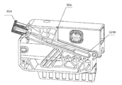
도 7a - 도 7f는 몇몇 실시예에 따른, 전달 모듈(504) 내의 그리고 그 둘레의 다양한 도면을 제공한다. 전달 모듈(504)의 많은 일반적인 특징들은 제1 테스트 카트리지 실시예의 전달 챔버(104)와 실질적으로 유사하다. 예를 들어, 양 전달 모듈은 경질의 내측 하우징 둘레에 감긴 순응성 재료를 포함하고, 중심 챔버를 향해 내측으로 이어지는 외부 상의 포트를 갖는다. 그러나, 전달 모듈(504) 상의 소정의 특징부들의 배열 및 설계는 도 7a - 도 7f에 관하여 본원에서 제공되는 바와 같이, 추가의 설명을 요구한다.7A-7F provide various views within and around the
전달 모듈(504)의 상이한 측면들로부터의 2개의 등각 개략도가 몇몇 실시예에 따라, 도 7a 및 도 7b에 도시되어 있다. 전달 모듈(504)은 내측 하우징(510) 둘레에 감긴 재킷(508)을 포함한다. 전달 모듈(504)은 또한 2개의 포트(712a, 712b)를 포함한다. 일 실시예에서, 포트(712a, 712b)들 각각은 전달 모듈(504)의 하부 부분 상에 배치된다. 하나의 예에서, 포트(712a, 712b)들은 실질적으로 서로 마주한다. 전달 모듈(504)은 또한 전달 모듈(504)의 상부 부분을 따른 제3 포트(706)를 포함할 수 있다. 일 실시예에서, 포트(712a, 712b, 706)는 전달 모듈(504) 내부의 중심 챔버 내로 이어진다. 각 포트(712a, 712b, 706)는 유체 전달을 위해 하우징(502)의 다양한 포트에 결합하기 위해 사용될 수 있다. 다른 예에서, 각 포트(712a, 712b, 706)는 테스트 카트리지 시스템(500) 내의 유체에 압력차를 인가하기 위해 가압 공급원에 결합될 수 있다. 하나의 실시예에서, 포트(712a, 712b)만이 유체를 전달하기 위해 사용되고, 포트(706)는 전달 모듈(504)의 중심 챔버를 가압 또는 감압하기 위해 사용된다.Two conformal schematics from different aspects of the
전달 모듈(504)은 또한 일 실시예에 따르면, 다양한 패턴화된 리지 및 형상을 포함한다. 전달 모듈(104) 상의 재킷(108)의 패턴화된 구조와 유사하게, 전달 모듈(504) 상의 패턴화된 영역은 하우징(502)의 다양한 포트에 정렬되어, 전달 모듈(504) 둘레에서 다양한 가압 영역 또는 밸브 영역을 형성할 수 있다. 예를 들어, 환상 구조물(704)이 하우징(502) 상의 포트 위에 정렬되어 그러한 포트를 밀봉할 수 있다. 일 실시예에 따르면, 환상 구조물(714)들의 군집체가 또한 제공된다. 환상 구조물(714)들의 군집체는 전달 모듈(504)의 위치에 기초하여 동시에 하우징(502)의 다양한 포트들 위에 정렬되도록 배열될 수 있다. 하나의 실시예에서, 환상 구조물(714)들의 군집체로부터의 환상 구조물은 하우징(502)의 적어도 2개의 포트들 사이에서 유체 다리로서 역할한다. 하나의 예에서, 유체는 동일한 환상 구조물 위에 정렬되는 2개의 포트를 통해 유동함으로써 하나의 채널로부터 다른 채널로 유동할 수 있다. 이러한 방식으로, 전달 모듈(504)의 중심 챔버를 통해 유체를 통과시킬 필요가 없이 하우징(502)의 상이한 채널들을 통해 유체를 이동시키는 것이 가능하다. 유체는 또한 일 실시예에 따르면, 임의의 포트(712a, 712b, 706)를 거쳐 전달 모듈(504)의 중심 챔버 내로 그리고 그의 외부로 여전히 유동할 수 있다.The
전달 모듈(504)의 재킷(508)은 또한 다양한 리지(707, 709)를 포함할 수 있다. 일 실시예에서, 리지(707)는 하우징(502)의 다양한 포트(610) 위에서 밀봉하도록 사용되고, 포트(610)들 중 하나의 포트만이 포트(712a)와 정렬된다. 리지(709)는, 예를 들어, 영역(711, 713)들과 같은 복수의 영역들 사이를 구분하기 위해 사용될 수 있다. 하나의 실시예에서, 영역(711, 713)들은 분리되어 가압될 수 있는 영역들을 나타낸다. 예를 들어, 영역(711)은 하우징(502) 내의 전달 모듈(504)의 위치로 인해 압력 포트(636)를 거쳐 가압될 수 있다. 가압 영역(711)은 포트(706)를 거쳐 전달 모듈(504)의 중심 챔버를 대응하여 가압하고, 전달 모듈(504)의 중심 챔버 내로 액체를 흡인하거나 그로부터 액체를 방출할 수 있다.
또한, 일 실시예에 따르면, 전달 모듈(504)을 액추에이터에 연결하기 위한 결합 영역(702)이 전달 모듈(504) 상에 도시되어 있다. 액추에이터는 이전에 설명된 제1 테스트 카트리지 시스템과 실질적으로 유사하게 하우징(502) 내에서 전달 모듈(504)을 측방향으로 병진 이동시키도록 설계될 수 있다.In addition, according to one embodiment, a
도 7c는 일 실시예에 따른, 전달 모듈(504)의 길이를 따른 전달 모듈(504)의 단면도를 도시한다. 전달 모듈(504)은 중심 챔버(716)를 포함한다. 뚜껑(506)이 중심 챔버(716)의 단부를 밀봉하기 위해 사용된다. 하나의 실시예에서, 뚜껑(506)은 제거 가능하도록 설계된다. 뚜껑(506)은 일 실시예에 따르면, 중심 챔버(716) 내의 임의의 액체를 배출하는 것을 돕기 위한 경사 표면(들)을 제공하기 위해 중심 챔버(716) 내로 연장한다. 구멍(708)이 액체를 하우징(502)의 다른 영역으로부터/으로 중심 챔버(716)로/로부터 전달하기 위해 중심 챔버(716) 내의 뚜껑(506)의 실질적으로 중간에 배치된다. 전달 채널(710)이 포트(712a, 712b)들 중 하나 또는 모두를 향해 액체를 보낼 수 있다.7C shows a cross-sectional view of the
도 7d는 일 실시예에 따른, 패널(718) 및 경사 구조물(720)을 포함하는 뚜껑(506)의 도면을 제공한다. 패널(718)은 중심 챔버(716)의 단부를 밀봉하기 위해 사용될 수 있고, 경사 구조물(720)은, 예를 들어, 중심 챔버(716) 내의 액체 샘플의 각 포트(712a 또는 712b)를 향한 이동을 용이하게 하도록 경사 표면을 제공한다. 구멍(708)이 또한 일 실시예에 따르면, 중심 챔버(716)를 소기시킬 때, 액체 전부를 적절하게 배출하기 위해 경사 구조물(720)의 최저 지점에 도시되어 있다.7D provides a view of a
도 7e는 일 실시예에 따른, 구멍(708) 및 전달 채널(710)을 도시하는 뚜껑(506) 아래로부터의 다른 도면을 도시한다. 하나의 예는 액체를 전달 모듈(504)의 측면들 상의 포트(712a, 712b)와 정렬시키기 위한 측면 채널(715)을 포함한다. 도시된 채널 구성은 유체를 중심 챔버(716) 내로 그리고 그의 외부로 유도하기 위한 단지 하나의 예이고, 제한적으로 간주되지 않아야 한다.FIG. 7E shows another view from under the
도 7f는 일 실시예에 따른, 전달 모듈(504)의 폭을 따른 전달 모듈(504)의 단면도를 도시한다. 재킷(508)이 내측 하우징(510) 둘레에 감겨서 관찰된다. 재킷(508)은 일 실시예에 따르면, 다양한 돌출부(724)를 포함한다. 돌출부(724)는 재킷(508) 상의 다양한 패턴화된 구조물을 나타낼 수 있다. 하나의 예에서, 돌출부(724)는 하우징(502)의 내벽에 대해 가압하여 다양한 영역(722a, 722b, 722c)을 생성한다. 각각의 영역은 하우징(502) 내에서의 전달 모듈(504)의 위치에 기초하여 분리되어 가압될 수 있다. 포트(712a, 712b)들은 일 실시예에 따르면, 각각 하우징(502)의 포트(610)들 중 하나 및 압력 포트(636)와 관련된 포트와 정렬되는 것으로 도시되어 있다. 전달 모듈(504)이 하우징(502) 내에서 측방향으로 이동할 때, 포트(712a 및/또는 712b)는 하우징(502)의 상이한 포트(610)들과 정렬될 수 있다. 또한, 일 실시예에 따르면, 경사 구조물(720) 및 측면 채널(715)이 중심 챔버(716) 내에 도시되어 있다. 예시적인 실시예에서, 측면 채널(715)은 U-형상으로 포트(712a, 712b)들 각각에 연결된다.7F shows a cross-sectional view of the
도 8a 및 8b는 몇몇 실시예에 따른, 분석을 위해 테스트 카트리지 시스템 내로 위치되는 스왑을 도시한다. 도 8a는 카트리지 하우징의 챔버(524b) 내에 위치된 스왑(802)을 도시한다. 챔버는 포트 뚜껑(512)으로 밀봉된다. 하나의 예에서, 스왑(802)은 80mm 정도의 길이를 갖는다. 챔버(524b)는 본 발명의 범주 또는 사상으로부터 벗어남이 없이 스왑의 임의의 길이를 수납하도록 치수 설정될 수 있다.8A and 8B illustrate a swap placed into a test cartridge system for analysis, in accordance with some embodiments. 8A shows a
도 8b는 더 긴 스왑(806)이 챔버(524b) 내로 위치되어 연장된 뚜껑(804)으로 밀봉되는 다른 실시예를 도시한다. 연장된 뚜껑(804)은 챔버(524b)보다 더 길고 챔버 개방부로부터 돌출한 스왑 위에서 밀봉하도록 사용될 수 있다. 하나의 예에서, 더 긴 스왑(806)은 길이가 대략 100mm이다. 더 긴 스왑(806)은 챔버(524b) 내에서 만곡되고 그리고/또는 구부러질 수 있다.8B illustrates another embodiment in which a
예시적인 작동 방법Example operation
카트리지 하우징 및 그의 대응하는 전달 챔버의 양 실시예의 다양한 챔버들 사이에서 유체 전달을 수행하기 위한 예시적인 방법이 아래에서 설명된다.An exemplary method for performing fluid transfer between the various chambers of both embodiments of the cartridge housing and its corresponding delivery chamber is described below.
도 9는 테스트 카트리지 시스템(100)의 제1 실시예를 통해 액체를 운반하기 위한 예시적인 방법(900)의 흐름도를 도시한다. 방법(900)은 테스트 카트리지 시스템(100)에서 수행될 수 있는 하나의 예시적인 작동 시퀀스를 설명하고, 제한적으로 간주되지 않아야 함을 이해하여야 한다. 또한, 방법(900)은 테스트 카트리지 시스템(500)의 제2 실시예를 사용하여 수행될 수도 있다.9 shows a flowchart of an
블록(902)에서, 전달 모듈(104)은 일 실시예에 따르면, 전달 모듈(104)의 입구 포트를 제1 챔버의 출구 포트에 정렬시키기 위해 카트리지 하우징(102) 내에서 측방향으로 이동된다. 전달 모듈(104)의 입구 포트는, 예를 들어, 1차 입구 포트(306)일 수 있다. 제1 챔버의 출구 포트는, 예를 들어, 입구 포트(228)들의 열 중 임의의 하나일 수 있다.In
블록(904)에서, 샘플이 일 실시예에 따르면, 인가되는 제1 압력차에 의해 제1 챔버로부터 전달 챔버(316) 내로 흡인된다. 일 실시예에서, 인가되는 압력차는 전달 압력 포트(308)에 인가된다. 인가되는 압력차는 샘플을 전달 챔버(316) 내로 흡인하기 위한 진공 압력일 수 있다. 샘플은 면봉 또는 액체로부터 제1 챔버로 도입될 수 있다. 제1 챔버는, 예를 들어, 내측 처리 챔버 또는 샘플 포트(114)와 관련된 처리 챔버일 수 있다. 추가로, 샘플은 액체, 반고체, 고체 등의 임의의 혼합물일 수 있다.In
블록(906)에서, 전달 모듈(104)은 일 실시예에 따르면, 전달 챔버(316)의 출구 포트를 제2 챔버의 입구 포트와 정렬시키기 위해 카트리지 하우징(102) 내에서 다시 측방향으로 이동된다. 전달 챔버(316)의 출구 포트는, 예를 들어, 1차 출구 포트(312)일 수 있다. 제2 챔버의 입구 포트는, 예를 들어, 액체 포트(210)들의 열 중 임의의 하나일 수 있다. 이와 같이, 제2 챔버의 입구 포트는 폐기물 챔버(218), 반응 챔버(216), 스왑 용출 챔버(206) 등과 같은, 카트리지 하우징(102)의 임의의 챔버로 이어질 수 있다.In
블록(908)에서, 샘플은 일 실시예에 따르면, 인가되는 제2 압력차에 의해 전달 챔버(316)로부터 제2 챔버로 흡인된다. 제2 압력차는 전달 압력 포트(308)에 인가되는 양압일 수 있다. 대안적으로, 제2 압력차는 액체를 대응하는 통기/흡입 포트(212)와 관련된 챔버 내로 흡인하기 위해 통기/흡입 포트(212)에 인가되는 진공 압력일 수 있다.At
본원의 설명이 주어지면 관련 기술 분야(들)의 당업자에 의해 이해되는 바와 같이 더 많은 액체 흡인 절차가 수행될 수 있음을 이해하여야 한다. 예를 들어, 블록(904) 이후에, 전달 챔버는 다른 보관 챔버 내에 보관된 다른 액체를 흡인하기 위해 그의 입구 포트를 카트리지 하우징(102)의 상부를 따른 제2 출구 포트에 정렬시킬 수 있다. 이러한 절차는 특정 분자 테스트에 대해 필요한 프로토콜에 의존하여 원하는 만큼 많은 회수로 반복될 수 있다.Given the description herein, it should be understood that more liquid aspiration procedures may be performed as understood by those skilled in the art. For example, after
다른 실시예에서, 블록(908)에 이어서, 추가의 단계가 샘플을 다시 전달 챔버 내로 흡인하고, 액체를 제3 챔버 내로 방출하기 위해 수행될 수 있다. 예를 들어, 제2 챔버는 스왑 용출 챔버(206)일 수 있고, 제3 챔버는 검출 챔버(216)들 중 하나일 수 있다. 임의의 개수의 챔버가 원하는 만큼 많은 회수로 흡인되거나 추출되는 액체를 가질 수 있다. 따라서, 시스템은 다양한 챔버들 사이에서 수많은 액체 전달 패턴을 허용한다.In another embodiment, following
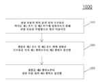
도 10은 테스트 카트리지 시스템(500)의 제2 실시예를 통해 액체를 운반하기 위한 예시적인 방법(1000)의 흐름도를 도시한다. 방법(1000)은 테스트 카트리지 시스템(500)에서 수행될 수 있는 하나의 예시적인 작동 시퀀스를 설명하며, 제한적으로 간주되지 않아야 함을 이해하여야 한다.10 shows a flowchart of an
블록(1002)에서, 전달 모듈(504)은 일 실시예에 따르면, 전달 모듈(504)의 외측 표면 상의 구조물을 적어도 제1 챔버와 관련된 제1 포트 및 제2 챔버와 관련된 제2 포트에 정렬시키기 위해 카트리지 하우징(502) 내에서 측방향으로 이동된다. 제1 챔버는, 예를 들어, 입구 저장소(622)일 수 있고, 제2 챔버는 보관 저장소(630a - 630g)들 중 하나일 수 있다. 전달 모듈(504)의 외측 표면 상의 구조물은 일 실시예에 따르면, 제1 포트 및 제2 포트 둘레에 끼워지는 환상 형상을 가질 수 있다.In
블록(1004)에서, 샘플이 일 실시예에 따르면, 적어도 전달 모듈(504)의 외측 표면 상의 구조물을 거쳐 제1 챔버로부터 제2 챔버로 흡인된다. 이러한 방식으로, 샘플은, 예를 들어, 전달 모듈(504)의 중심 챔버를 통과하지 않고서, 제1 챔버와 제2 챔버 사이에서 이동할 수 있다.In
블록(1006)에서, 샘플은 일 실시예에 따르면, 제2 챔버로부터 제3 챔버로 흡인된다. 제3 챔버는 전달 모듈(504)의 중심 챔버(716)일 수 있고, 액체는 전달 모듈(504)의 벽을 통한 포트를 거쳐 중심 챔버(716)로 진입할 수 있다. 포트는, 예를 들어, 도 7a 및 도 7b에 도시된 임의의 유체 포트(706, 712a, 712b)일 수 있다. 제3 챔버는 샘플을 혼합 또는 여과하기 위한 구성요소를 포함할 수 있다. 다른 실시예에서, 전달 모듈(504)은 전달 모듈(504)의 포트를 하우징(502)의 다른 포트에 정렬시키고 그의 중심 챔버 내의 샘플을 정렬된 포트를 통해 방출하기 위해, 측방향으로 이동할 수 있다. 본원의 설명이 주어지면 관련 기술 분야(들)의 당업자에 의해 이해되는 바와 같이 더 많은 액체 흡인 절차가 수행될 수 있음을 이해하여야 한다.At
예Yes
테스트 카트리지 시스템(100)을 사용하여 수행되는 2개의 예시적인 프로토콜이 이제 설명된다. 제1 예시적인 프로토콜은 실시간 PCR 검출에 관한 것이고, 제2 예시적인 프로토콜은 면역 검정에 관한 것이다. 여기서 언급되는 단계들은 각각의 테스트를 수행하는 것은 물론, 시스템을 사용하기 위한 가능한 예를 제공함을 이해하여야 한다.Two exemplary protocols performed using the
PCR 프로토콜PCR protocol
예시적인 PCR 프로토콜은 카트리지 하우징(102) 둘레의 반응 챔버는 물론 많은 처리 챔버를 이용한다. 하나의 예에서, PCR 프로토콜은 도 2a에 도시된 카트리지 하우징 실시예를 사용한다. 프로토콜은 또한 도 6a - 도 6b에 도시된 카트리지 하우징 실시예를 사용하여 수행될 수 있음을 이해하여야 한다. 이러한 예에서, 5개의 보관 챔버가 사용되고, 각각은 미리 장입된 용액을 담는다. 보관 챔버는 다음과 같이 라벨링된다:Exemplary PCR protocols utilize many process chambers as well as reaction chambers around
R1: 세척-2 완충제를 담음R1: contains wash-2 buffer
R2: 용해 완충제를 담음R2: contains lysis buffer
R3: 용출 완충제를 담음R3: contains elution buffer
R4: 세척-3 완충제를 담음R4: contains Wash-3 buffer
R5: 세척-1 완충제를 담음R5: contains Wash-1 buffer
예시적인 PCR 절차는 위에서 설명된 예시적인 테스트 카트리지 시스템(100)을 참조하여 본원에서 설명된 작업 흐름을 사용하여 수행될 수 있다. 유사한 단계들이 또한 테스트 카트리지 시스템(500) 상에 도시된 다양한 챔버 및 채널을 사용하여 수행될 수 있다. 샘플은 스왑 리셉터클(114) 내의 스왑을 거쳐 테스트 카트리지 시스템(100) 내로 도입된다. 대안적으로, 샘플은 통합형 비드 비터 시스템에 의해 용해되도록 제2 입구를 거쳐 직접 내측 처리 챔버 내로 도입될 수 있다.Exemplary PCR procedures can be performed using the workflow described herein with reference to the exemplary
샘플이 테스트 카트리지 시스템(100) 내로 도입되면, 전체 테스트 카트리지는 분석기 내로 위치된다. 분석기는 전달 모듈(104)을 이동시키기 위한 액추에이터, PCR 반응을 수행하기 위한 하나 이상의 가열 요소, 및 광학 측정 구성요소를 제공한다. 분석기는 아울러 카트리지 하우징(102) 둘레의 압력 포트에 결합하여, 필요한 압력차를 인가할 수 있다.Once the sample is introduced into the
전달 모듈(104)은 용해 완충제를 R2로부터 전달 챔버 내로 흡인하도록 정렬된다. 전달 모듈(104)은 용해 완충제를 스왑 용출 챔버(206)로 이동시키도록 정렬되고, 여기서 스왑으로부터의 샘플이 용해 완충제 내에서 재현탁된다. 샘플은, 용해 완충제와 함께, 그 다음 처리 포트(204)를 거쳐 내측 처리 챔버 내로 이동되어, 샘플 내의 세포에 대한 용해를 수행하고 DNA 및/또는 RNA를 방출할 수 있다. 용해 절차에 이어서, 샘플은 이후에 "용해물"로 불린다.
용해물은 전달 챔버에 인가되는 진공 압력에 의해 내측 처리 챔버로부터 전달 챔버 내로 다시 흡인된다. 그 다음, 전달 모듈(104)은 그의 출구 포트를 폐기물 챔버와 관련된 포트에 정렬시키기 위해 측방향으로 이동된다. 그러나, 필터가 DNA 서열을 포착하기 위해 폐기물 챔버로부터 상류에 배치된다. 따라서, 전달 챔버에 양압을 인가한 후에, 용해물은 필터를 통해 계속하여 폐기물 챔버로 통과한다. DNA는 필터 내에 잔류할 것이고, 다량의 임의의 원치 않는 물질은 폐기물 챔버로 통과할 것이다. 필터는, 예를 들어, 핵산 서열을 포획하기 위한 실리케이트 매트릭스 또는 복수의 실리카 비드일 수 있다.The melt is drawn back from the inner processing chamber into the delivery chamber by the vacuum pressure applied to the delivery chamber. The
전달 모듈(104)은 R5와 정렬되도록 이동하여, 세척-1 완충제를 전달 챔버 내로 흡인한다. 이어서, 세척-1 완충제가 필터 내에서 임의의 원치 않는 물질을 추가로 제거하기 위해 필터를 통과한다. 완충제는 폐기물 챔버로 통과한다. 제2 세척 단계가 그 다음 세척-2 완충제에 의해 수행된다. 전달 모듈(104)은 R1과 정렬되어 세척-2 완충제를 흡인하고, 필터를 포함하는 유체 채널과 정렬되도록 다시 이동한다. 세척-2는 필터를 통해 폐기물 챔버 상으로 통과한다.The
이러한 스테이지에서, DNA가 전달 챔버 내로 복귀될 수 있기 전에 전달 챔버를 세척하는 것이 요구될 수 있다. 이와 같이, 전달 모듈(104)은 R4와 정렬되고, 세척-3 완충제가 전달 챔버 내로 흡인된다. 세척 완충제는 전달 챔버 둘레에서 혼합될 수 있다. 추가로, 세척-3 완충제는, 예를 들어, 내측 처리 챔버로 전달될 수 있다.At this stage, it may be necessary to wash the delivery chamber before DNA can be returned into the delivery chamber. As such,
전달 모듈(104)은 그의 상부 입구 포트를 R3의 출구 포트에 정렬시키기 위해 측방향으로 이동된다. 진공 압력이 용출 완충제를 전달 챔버 내로 흡인하기 위해 인가된다. 그 후에, 전달 모듈(104)은 그의 출구 포트를 카트리지 하우징(102) 상의 용출 챔버(220)와 관련된 포트에 정렬시키기 위해 측방향으로 이동된다. 용출 완충제는 전달 챔버에 인가되는 양압에 의해 또는 용출 챔버(220)에 연결된 통기/흡입 포트로부터의 진공 압력에 의해, 용출 챔버(220) 내로 이동된다.The
DNA는 이제 필터로부터 제거되어 전달 챔버 내로 복귀될 준비가 된다. 카트리지 하우징(102)의 용출 챔버(220)로부터의 용출 완충제는 DNA 용액을 수납하기 위해, 필터를 통해 진공 압력을 사용하여 다시 올바른 포트에 정렬된 전달 챔버 내로 흡인된다. 전달 모듈(104)은 이제 다양한 반응 챔버들의 포트들 사이에서 순차적으로 이동하여, 인가되는 양압에 의해, 액체를 각각의 챔버 내로 전달할 수 있다.The DNA is now removed from the filter and ready to return to the delivery chamber. Elution buffer from the
각각의 반응 챔버는 DNA에서 PCR을 수행하기 위해 필요한 시약을 담을 수 있다. 일 실시예에서, 시약은 PCR을 수행하기 위해 필요한 임의의 시약을 함유하는 미리 장입된, 동결 건조 펠릿이다. 시약은 DNA 용액이 각각의 챔버 내로 보내질 때, 빠르게 재수화될 것이다.Each reaction chamber may contain the reagents needed to perform PCR on DNA. In one embodiment, the reagent is a preloaded, lyophilized pellet containing any reagent needed to perform the PCR. The reagent will quickly rehydrate when the DNA solution is sent into each chamber.
DNA 용액이 최종적으로 반응 챔버들 중 하나 이상 내로 전달되면, 나머지 과정이 분석기에 의해 수행될 수 있다. 즉, DNA를 활성화하고, 변성시키고, 풀고, 연장시키는 것 중 적어도 하나를 위한 가열 및 냉각 단계의 사이클링이 수행될 수 있다. 사이클링이 완료되면, 분석기의 광학 측정 시스템은 각각의 반응 챔버로부터 데이터를 수집하여 테스트 결과를 최종 사용자에게 제공할 수 있다.Once the DNA solution is finally delivered into one or more of the reaction chambers, the rest of the process can be performed by the analyzer. That is, cycling of heating and cooling steps for at least one of activating, denaturing, unwinding, and extending DNA can be performed. Once cycling is complete, the analyzer's optical measurement system can collect data from each reaction chamber and provide test results to the end user.
면역 검정Immunoassay
예시적인 면역 검정은 카트리지 하우징(102) 둘레의 다양한 처리 챔버들은 물론 보관 챔버들 중 적어도 3개를 이용한다. 하나의 예에서, 면역 검정은 도 2b에 도시된 카트리지 하우징 실시예를 사용한다. PCR 프로토콜과 유사하게, 보관 챔버는 검정을 수행하기 위한 미리 장입된 용액을 담는다. 추가로, 특정 포착 항체가 관심 항원에 대한 결합 부위를 제공하기 위해 검출 챔버(226) 내에 고정될 수 있다. 형광 표지된 항체가 또한 동결 건조된 상태로 반응 챔버(224) 내로 미리 장입될 수 있다. 이러한 예에서, 보관 챔버는 다음과 같이 라벨링된다:An exemplary immunoassay utilizes at least three of the storage chambers as well as the various processing chambers around the
R1: 세척-1 완충제R1: Wash-1 Buffer
R2: 검정 완충제R2: assay buffer
R3: 세척-2 완충제R3: wash-2 buffer
면역 검정은 명확하게 하기 위해 예시적인 테스트 카트리지 시스템(100)을 참조하여 본원에서 설명된 작업 흐름을 사용하여 수행될 수 있다. 샘플은 내측 처리 챔버로 직접 이어지는 입구를 통해 카트리지 하우징(102) 내로 도입될 수 있다. 도입되면, 테스트 카트리지 시스템(100)은 분석기 내로 위치된다. 나머지 프로토콜은 분석기 시스템에 의해 자동으로 수행될 수 있다. 전달 모듈(104)이 내측 처리 챔버와 측방향으로 정렬되고, 샘플은 인가되는 진공 압력에 의해 전달 챔버 내로 흡인된다.Immunoassay may be performed using the workflow described herein with reference to exemplary
샘플이 전달 챔버 내부에 있으면, 전달 모듈(104)은 그의 출구 포트를 용출 챔버로 이어지는 포트에 정렬시키기 위해 다시 측방향으로 이동한다. 용출 챔버로부터의 샘플은 그 다음 전혈로부터 혈장을 획득하기 위해 박막을 통과함으로써 전달 챔버로 이동된다. (관심 항원을 함유하는) 혈장 샘플이 다시 전달 챔버 내에 있으면, 전달 모듈(104)은 R2와 정렬되어, 검정 완충제를 전달 챔버 내로 흡인할 수 있다. 검정 완충제와 혈장 샘플이 전달 챔버 내에서 혼합된다.Once the sample is inside the delivery chamber, the
혈장 샘플과 검정 완충제가 혼합되면, 전달 모듈(104)은 그의 출구 포트를 동결 건조된 형광 표지 항체를 갖는 반응 챔버(224)로 이어지는 포트에 정렬시키기 위해 다시 측방향으로 이동한다. 샘플 + 검정 완충제 혼합물은 반응 챔버(224) 내에서 형광 표지된 항체를 재수화하도록 작용한다. 재수화된 형광 항체, 샘플 혈장, 및 검정 완충제가 모두 함께 조합되어 혼합된다. 이러한 스테이지에서, 관심 항원이 혼합물 내에 존재하면, 형광 표지된 항체가 그에 결합될 것이다. 일 실시예에서, 가열 및/또는 혼합이 반응을 향상시키기 위해 수행될 수 있다.Once the plasma sample and assay buffer are mixed, the
결과적인 혼합물은 반응 챔버(224)로부터 검출 챔버(226)들 각각으로 운반된다. 다시 한번, 혼합물은 고정된 포착 항체와 혼합물 내의 항원 사이의 상호 작용을 보장하기 위해 각각의 검출 챔버(226) 내에서 온화하게 혼합되거나 가열될 수 있다.The resulting mixture is transferred from the
혼합이 완료되면, 전달 모듈(104)은 R1과 정렬되어, 세척-1 완충제를 전달 챔버 내로 흡인한다. 세척-1 완충제는 먼저 반응 챔버 내로 그리고 이어서 혼합물을 담은 각각의 검출 챔버 내로 전달될 수 있다. 세척-1 완충제는 임의의 미결합 물질을 제거한다. 세척-1 완충제는 계속하여 검출 챔버를 통해 폐기물 챔버 내로 통과한다.Once mixing is complete, the
제2 세척 단계가 수행될 수 있다. 전달 모듈(104)은 R3와 정렬되어, 세척-2 완충제를 전달 챔버 내로 흡인한다. 세척-2 완충제는 먼저 반응 챔버 내로 그리고 이어서 혼합물을 담은 각각의 검출 챔버 내로 전달될 수 있다. 세척-2 완충제는 임의의 미결합 물질을 제거한다. 세척-2 완충제는 계속하여 검출 챔버를 통해 폐기물 챔버 내로 통과한다. 이러한 스테이지에서, 고정된 항체에 대한 임의의 결합된 물질은 결합된 형광 표지 항체와 함께 있는 관심 항원이어야 한다.A second wash step can be performed.
분석기의 광학 측정 시스템은 이제 수신된 형광 신호에 기초하여 항원의 양을 정량하기 위해 각각의 검출 챔버에 대해 사용될 수 있다. 수집된 데이터는, 예를 들어, 최종 사용자를 위한 정량 결과를 획득하기 위해 보정기에 의해 이전에 수행된 표준 곡선에 대해 플로팅될 수 있다.The analyzer's optical measurement system can now be used for each detection chamber to quantify the amount of antigen based on the received fluorescence signal. The collected data can be plotted against a standard curve previously performed by a calibrator, for example to obtain quantitative results for the end user.
위에서 설명된 각 프로토콜의 종료 시에, 전체 테스트 카트리지 시스템(100)은 분석기로부터 제거되어 안전하게 폐기될 수 있음을 이해하여야 한다. 다른 실시예에서, 검출 챔버들 중 하나 이상 내의 결과적인 용액은 추가의 분석을 위해 추출될 수 있다. 시스템이 자납식이므로, 많은 테스트 카트리지가 실험들 사이에서 교차 오염 또는 오손에 대한 우려가 없이 동일한 분석기에서 사용될 수 있다.At the end of each protocol described above, it should be understood that the entire
'발명의 내용' 및 '요약서' 부분이 아닌 '발명을 실시하기 위한 구체적인 내용' 부분이 특허청구범위를 해석하기 위해 사용되도록 의도됨을 이해하여야 한다. '발명의 내용' 및 '요약서' 부분은 본 발명자(들)에 의해 고려되는 본 발명의 전부는 아니지만 하나 이상의 예시적인 실시예를 설명할 수 있고, 따라서 본 발명 및 첨부된 특허청구범위를 어떠한 방식으로도 제한하도록 의도되지 않는다.It is to be understood that the "specifications for carrying out the invention" part, rather than the "inventions" and "summary" parts, are intended to be used to interpret the claims. The 'Invention' and 'Summary' sections may describe one or more exemplary embodiments, but not all of the inventions contemplated by the inventor (s), and therefore, in no way may the invention and the appended claims. It is not intended to be limiting either.
본 발명의 실시예는 규정된 기능들의 구현예 및 이들의 관계를 예시하는 기능적 구성 블록의 도움으로 위에서 설명되었다. 이러한 기능적 구성 블록의 경계는 설명의 편의를 위해 본원에서 임의로 한정되었다. 대안적인 경계가 규정된 기능들 및 이들의 관계가 적절하게 수행되는 한 한정될 수 있다.Embodiments of the present invention have been described above with the aid of functional building blocks illustrating implementations of defined functions and their relationships. The boundaries of these functional building blocks have been arbitrarily defined herein for the convenience of the description. Alternative boundaries may be defined so long as the defined functions and their relationships are properly performed.
구체적인 실시예의 상기 설명은, 타인인 본 기술 분야의 통상의 기술 내의 지식을 적용함으로써, 본 발명의 일반적인 개념으로부터 벗어남이 없이, 부적당한 실험이 없이, 그러한 특정 실시예를 쉽게 변형하고 그리고/또는 다양한 용도에 대해 적응시킬 수 있을 정도로 본 발명의 일반적인 특질을 완전히 드러낼 것이다. 그러므로, 그러한 적응 및 변형은 본원에서 제시되는 교시 및 안내에 기초하여, 개시되는 실시예의 등가물들의 의미 및 범위 내에 있도록 의도된다. 본원의 문구 또는 용어는 설명의 목적이며 제한의 목적이 아니어서, 본 명세서의 용어 또는 문구는 교시 및 안내에 비추어 당업자에 의해 해석되어야 함을 이해하여야 한다.The above description of specific embodiments can be readily modified and / or modified to such specific embodiments without departing from the general concept of the invention, without undue experimentation, by applying knowledge within the ordinary skill of the art as others. It will fully reveal the general features of the present invention to the extent that it is adaptable to its use. Therefore, such adaptations and modifications are intended to be within the meaning and scope of equivalents of the disclosed embodiments based on the teachings and guidance presented herein. It is to be understood that the phrase or terminology herein is for the purpose of description and not of limitation, that the term or phrase herein is to be interpreted by one of ordinary skill in the art in light of the teaching and guidance.
본 발명의 범위 및 사상은 임의의 전술한 예시적인 실시예에 의해 제한되지 않아야 하고, 다음의 특허청구범위 및 그의 등가물에 따라서만 한정되어야 한다.The scope and spirit of the present invention should not be limited by any of the above-described exemplary embodiments, but should be defined only in accordance with the following claims and their equivalents.
100: 테스트 카트리지 시스템
102: 카트리지 하우징
104: 전달 모듈
106: 뚜껑
108: 재킷
110: 내측 하우징100: test cartridge system
102: cartridge housing
104: delivery module
106: lid
108: jacket
110: inner housing
Claims (29)
중심 챔버를 에워싸는 내측 하우징; 및
재킷의 외측 표면을 따른 패턴화된 리지 - 패턴화된 리지는 전달 모듈이 패턴화된 리지와 접촉하게 되는 엔클로저 내에 배치될 때, 재킷의 외측 표면을 따라 복수의 밸브 영역을 형성하도록 구성됨 -; 및 재킷 및 내측 하우징을 통해 중심 챔버 내로 연장하는 복수의 포트를 포함하는, 내측 하우징 둘레에 형성된 재킷
을 포함하고,
복수의 밸브 영역들 중 하나는 복수의 밸브 영역 내의 다른 영역으로부터 분리되어 가압되도록 구성되는,
전달 모듈.A delivery module configured to store and transport a liquid sample,
An inner housing enclosing the central chamber; And
Patterned ridges along the outer surface of the jacket, wherein the patterned ridges are configured to form a plurality of valve regions along the outer surface of the jacket when the delivery module is disposed in an enclosure into contact with the patterned ridges; And a plurality of ports extending into the central chamber through the jacket and the inner housing.
Including,
One of the plurality of valve regions is configured to be pressurized separately from another region in the plurality of valve regions,
Delivery module.
중심 챔버를 갖는 전달 모듈의 제1 포트를 제1 챔버의 포트에 정렬시키기 위해 전달 모듈을 측방향으로 병진 이동시키는 단계;
샘플을 제1 압력차에 의해 제1 챔버로부터 중심 챔버 내로 흡인하는 단계;
전달 모듈의 제2 포트를 제2 챔버의 포트에 정렬시키기 위해 전달 모듈을 측방향으로 병진 이동시키는 단계; 및
샘플을 제2 압력차에 의해 중심 챔버로부터 제2 챔버 내로 흡인하는 단계
를 포함하는 방법.Using a test cartridge,
Translating the delivery module laterally to align the first port of the delivery module with the central chamber to the port of the first chamber;
Sucking the sample from the first chamber into the central chamber by the first pressure difference;
Translating the delivery module laterally to align the second port of the delivery module to the port of the second chamber; And
Aspirating the sample from the central chamber into the second chamber by the second pressure difference
How to include.
샘플을 제2 챔버 내에서 처리하는 단계;
샘플을 제3 압력차에 의해 제2 챔버로부터 중심 챔버 내로 흡인하는 단계;
전달 모듈의 제2 포트를 제3 챔버의 포트에 정렬시키기 위해 전달 모듈을 측방향으로 병진 이동시키는 단계;
샘플을 제4 압력차에 의해 중심 챔버로부터 제3 챔버 내로 흡인하는 단계; 및
제3 챔버 내에 있을 때 샘플들의 하나 이상의 정성(quality)을 측정하는 단계
를 추가로 포함하는 방법.The method of claim 12,
Processing the sample in a second chamber;
Drawing the sample into the central chamber from the second chamber by a third pressure difference;
Translating the delivery module laterally to align the second port of the delivery module with the port of the third chamber;
Sucking the sample from the central chamber into the third chamber by a fourth pressure difference; And
Measuring one or more qualities of the samples when in the third chamber
How to further include.
샘플을 제2 챔버 내에서 처리하는 단계;
샘플을 제3 압력차에 의해 제2 챔버로부터 중심 챔버 내로 흡인하는 단계;
전달 모듈의 제2 포트를 제3 챔버의 포트에 정렬시키기 위해 전달 모듈을 측방향으로 병진 이동시키는 단계;
샘플을 제4 압력차에 의해 중심 챔버로부터 제3 챔버 내로 흡인하는 단계;
샘플을 제3 챔버 내에서 처리하는 단계;
전달 모듈의 제2 포트를 제4 챔버의 포트에 정렬시키기 위해 전달 모듈을 측방향으로 병진 이동시키는 단계;
샘플을 제5 압력차에 의해 중심 챔버로부터 제4 챔버 내로 흡인하는 단계; 및
제4 챔버 내에 있을 때 샘플들의 하나 이상의 정성을 측정하는 단계
를 추가로 포함하는 방법.The method of claim 12,
Processing the sample in a second chamber;
Drawing the sample into the central chamber from the second chamber by a third pressure difference;
Translating the delivery module laterally to align the second port of the delivery module with the port of the third chamber;
Sucking the sample from the central chamber into the third chamber by a fourth pressure difference;
Processing the sample in a third chamber;
Translating the delivery module laterally to align the second port of the delivery module to the port of the fourth chamber;
Sucking the sample from the central chamber into the fourth chamber by a fifth pressure difference; And
Measuring one or more qualitative of the samples when in the fourth chamber
How to further include.
전달 모듈의 외측 표면 상의 구조물을 제1 챔버와 관련된 제1 포트 및 제2 챔버와 관련된 제2 포트와 정렬시키기 위해 하우징 내에서 전달 모듈을 측방향으로 병진 이동시키는 단계;
샘플을 적어도 제1 포트 및 제2 포트 위에 정렬된 구조물을 거쳐 제1 챔버로부터 제2 챔버로 흡인하는 단계; 및
샘플을 전달 모듈의 벽을 통한 포트를 거쳐 제2 챔버로부터 전달 모듈 내에 위치된 제3 챔버로 흡인하는 단계
를 포함하는 방법.Using a test cartridge,
Translating the delivery module laterally within the housing to align the structure on the outer surface of the delivery module with the first port associated with the first chamber and the second port associated with the second chamber;
Aspirating the sample from the first chamber to the second chamber via a structure aligned over at least the first port and the second port; And
Aspirating the sample from the second chamber to a third chamber located in the delivery module via a port through the wall of the delivery module
How to include.
Applications Claiming Priority (3)
| Application Number | Priority Date | Filing Date | Title |
|---|---|---|---|
| US201261611784P | 2012-03-16 | 2012-03-16 | |
| US61/611,784 | 2012-03-16 | ||
| PCT/EP2013/055432 WO2013135878A1 (en) | 2012-03-16 | 2013-03-15 | A test cartridge with integrated transfer module |
Related Parent Applications (1)
| Application Number | Title | Priority Date | Filing Date |
|---|---|---|---|
| KR1020147028632A Division KR102059004B1 (en) | 2012-03-16 | 2013-03-15 | A test cartridge with integrated transfer module |
Publications (2)
| Publication Number | Publication Date |
|---|---|
| KR20190109596A true KR20190109596A (en) | 2019-09-25 |
| KR102168912B1 KR102168912B1 (en) | 2020-10-23 |
Family
ID=47915188
Family Applications (2)
| Application Number | Title | Priority Date | Filing Date |
|---|---|---|---|
| KR1020197027359A KR102168912B1 (en) | 2012-03-16 | 2013-03-15 | A test cartridge with integrated transfer module |
| KR1020147028632A KR102059004B1 (en) | 2012-03-16 | 2013-03-15 | A test cartridge with integrated transfer module |
Family Applications After (1)
| Application Number | Title | Priority Date | Filing Date |
|---|---|---|---|
| KR1020147028632A KR102059004B1 (en) | 2012-03-16 | 2013-03-15 | A test cartridge with integrated transfer module |
Country Status (14)
| Country | Link |
|---|---|
| US (4) | US9062342B2 (en) |
| EP (2) | EP2825309B1 (en) |
| JP (4) | JP6153951B2 (en) |
| KR (2) | KR102168912B1 (en) |
| CN (4) | CN104411406B (en) |
| AU (1) | AU2013234281B2 (en) |
| BR (1) | BR112014022962B1 (en) |
| CA (1) | CA2867414C (en) |
| DK (1) | DK2825309T3 (en) |
| ES (1) | ES2682281T3 (en) |
| HK (1) | HK1243724A1 (en) |
| RU (2) | RU2767695C2 (en) |
| WO (1) | WO2013135878A1 (en) |
| ZA (1) | ZA201500088B (en) |
Families Citing this family (45)
| Publication number | Priority date | Publication date | Assignee | Title |
|---|---|---|---|---|
| US8448499B2 (en) | 2008-12-23 | 2013-05-28 | C A Casyso Ag | Cartridge device for a measuring system for measuring viscoelastic characteristics of a sample liquid, a corresponding measuring system, and a corresponding method |
| EP2825309B1 (en) | 2012-03-16 | 2018-05-16 | Stat-Diagnostica & Innovation, S.L. | A test cartridge with integrated transfer module |
| DE102012222828A1 (en) * | 2012-12-11 | 2014-06-12 | Agilent Technologies, Inc. - A Delaware Corporation - | Pre-filled liquid cartridge for supplying a sample separator with a working fluid |
| US11187713B2 (en) * | 2013-01-14 | 2021-11-30 | Stratec Se | Laboratory module for storing and feeding to further processing of samples |
| KR102094496B1 (en) | 2013-03-11 | 2020-03-30 | 큐 헬스 인코퍼레이티드 | Systems and methods for detection and quantification of analytes |
| EP3042196A4 (en) * | 2013-09-06 | 2017-04-05 | Theranos, Inc. | Devices, systems, methods and kits for receiving a swab |
| ES2887222T3 (en) | 2014-04-24 | 2021-12-22 | Lucira Health Inc | Colorimetric detection of nucleic acid amplification |
| USD745423S1 (en) | 2014-05-12 | 2015-12-15 | Cue Inc. | Automated analyzer test cartridge and sample collection device for analyte detection |
| JP2017527288A (en) | 2014-09-04 | 2017-09-21 | セラノス, インコーポレイテッドTheranos, Inc. | Pathogen and antimicrobial resistance test |
| CN110038652B (en) * | 2014-09-11 | 2021-12-07 | 克忧健康公司 | Systems and methods for detecting and quantifying analytes |
| US10775370B2 (en) * | 2015-07-17 | 2020-09-15 | Stat-Diagnostica & Innovation, S.L. | Fluidic system for performing assays |
| BR122020004273B1 (en) | 2015-07-17 | 2022-11-29 | Cue Health Inc | SAMPLE ANALYSIS CARTRIDGE |
| US10413902B2 (en) | 2015-07-17 | 2019-09-17 | Stat-Diagnostica & Innovation, S.L. | Apparatus for sample separation and collection |
| US10300486B2 (en) | 2015-07-17 | 2019-05-28 | Stat-Diagnostica & Innovation, S.L. | Dry chemistry container |
| WO2017160836A1 (en) | 2016-03-14 | 2017-09-21 | Diassess Inc. | Systems and methods for performing biological assays |
| US11291995B2 (en) | 2016-03-14 | 2022-04-05 | Lucira Health, Inc. | Selectively vented biological assay devices and associated methods |
| CA3015376C (en) | 2016-03-14 | 2023-11-14 | Diassess Inc. | Devices and methods for biological assay sample preparation and delivery |
| WO2017191691A1 (en) * | 2016-05-02 | 2017-11-09 | インテグリカルチャー株式会社 | Growth induction system, growth induction control apparatus, growth induction control method, and growth induction control program |
| JP7131833B2 (en) * | 2016-05-17 | 2022-09-06 | インテグレーテッド ナノ-テクノロジーズ,インコーポレイティド | Filtration column assemblies for diagnostic assay systems |
| US10450144B2 (en) * | 2016-05-27 | 2019-10-22 | Biomerieux, Inc. | System and method for transferring specimen containers between detection instruments |
| CN106226254B (en) * | 2016-08-03 | 2019-06-07 | 天津喜诺生物医药有限公司 | A kind of micro-fluidic chip and preparation method thereof for biological detection |
| US11237161B2 (en) | 2017-01-25 | 2022-02-01 | Cue Health Inc. | Systems and methods for enhanced detection and quantification of analytes |
| EP3354342A1 (en) * | 2017-01-26 | 2018-08-01 | Eidgenössische Anstalt für Wasserversorgung, Abwasserreinigung und Gewässerschutz, Eawag | Device and method for producing individually processed fluid samples |
| US11080848B2 (en) | 2017-04-06 | 2021-08-03 | Lucira Health, Inc. | Image-based disease diagnostics using a mobile device |
| USD839447S1 (en) * | 2017-04-20 | 2019-01-29 | Hemosonics Llc | Hemostasis measurement cartridge |
| USD841184S1 (en) * | 2017-06-06 | 2019-02-19 | Hemosonics Llc | Transparent hemostasis measurement cartridge |
| US10549275B2 (en) | 2017-09-14 | 2020-02-04 | Lucira Health, Inc. | Multiplexed biological assay device with electronic readout |
| US20190217292A1 (en) * | 2018-01-18 | 2019-07-18 | Stat-Diagnostica & Innovation S.L. | Dry Chemistry Container |
| USD878622S1 (en) * | 2018-04-07 | 2020-03-17 | Precision Nanosystems Inc. | Microfluidic chip |
| US11925932B2 (en) | 2018-04-24 | 2024-03-12 | Hewlett-Packard Development Company, L.P. | Microfluidic devices |
| WO2020018074A1 (en) | 2018-07-17 | 2020-01-23 | Hewlett-Packard Development Company, L.P. | Droplet ejectors to provide fluids to droplet ejectors |
| WO2019209374A1 (en) | 2018-04-24 | 2019-10-31 | Hewlett-Packard Development Company, L.P. | Sequenced droplet ejection to deliver fluids |
| DE102018111834A1 (en) * | 2018-05-16 | 2019-11-21 | Mildendo Gesellschaft für mikrofluidische Systeme mbH | Microfluidic device and method of using same for separating, purifying and concentrating components of fluidic media, |
| US11547993B2 (en) | 2018-07-17 | 2023-01-10 | Hewlett-Packard Development Company, L.P. | Droplet ejectors with target media |
| EP3647781B1 (en) | 2018-10-29 | 2024-05-01 | EXIAS Medical GmbH | Measuring cartridge for measuring a liquid sample |
| USD910200S1 (en) | 2018-12-21 | 2021-02-09 | Lucira Health, Inc. | Test tube |
| KR20220147633A (en) * | 2020-02-27 | 2022-11-03 | 원 바이오메드 피티이 엘티디. | Devices, systems and methods for isolating biological material |
| WO2021219533A1 (en) | 2020-04-29 | 2021-11-04 | Boehringer Ingelheim Vetmedica Gmbh | Cartridge, system and method for amplification of at least one analyte |
| USD953561S1 (en) | 2020-05-05 | 2022-05-31 | Lucira Health, Inc. | Diagnostic device with LED display |
| USD962470S1 (en) | 2020-06-03 | 2022-08-30 | Lucira Health, Inc. | Assay device with LCD display |
| WO2022132134A1 (en) * | 2020-12-15 | 2022-06-23 | Hewlett-Packard Development Company, L.P. | Sample swab including a heating instrument |
| WO2022139812A1 (en) * | 2020-12-22 | 2022-06-30 | Hp Health Solutions Inc. | Dual mechanical heating control |
| WO2022140447A1 (en) * | 2020-12-23 | 2022-06-30 | Nextgen Jane, Inc. | Systems and methods for preservation of a cervicovaginal fluid sample |
| WO2022251508A1 (en) * | 2021-05-28 | 2022-12-01 | Proof Diagnostics | Reaction cartridge |
| KR102483098B1 (en) * | 2022-04-06 | 2023-01-02 | 남택신 | Sample insertion type diagnostic kit |
Citations (7)
| Publication number | Priority date | Publication date | Assignee | Title |
|---|---|---|---|---|
| US20020106787A1 (en) * | 1999-04-29 | 2002-08-08 | James Benn | Device for repid DNA sample processing with integrated liquid handling, thermocycling, and purification |
| JP2005180983A (en) * | 2003-12-17 | 2005-07-07 | Hitachi High-Technologies Corp | Chemical analyzer and structure for chemical analysis |
| US20050161669A1 (en) * | 2002-08-02 | 2005-07-28 | Jovanovich Stevan B. | Integrated system with modular microfluidic components |
| US20050176037A1 (en) * | 2003-12-12 | 2005-08-11 | Ubaldo Mastromatteo | Integrated semiconductor microreactor for real-time monitoring of biological reactions |
| US20060030038A1 (en) * | 1999-05-28 | 2006-02-09 | Chpheid | Apparatus and method for cell disruption |
| US20070154355A1 (en) * | 2004-08-18 | 2007-07-05 | Manfred Berndt | Microfluidic assembly with coupled microfluidic devices |
| WO2011047494A1 (en) * | 2009-10-21 | 2011-04-28 | Biocartis Sa | Manifold for a fluidic cartridge |
Family Cites Families (210)
| Publication number | Priority date | Publication date | Assignee | Title |
|---|---|---|---|---|
| SE454115B (en) | 1982-09-13 | 1988-03-28 | Wallac Oy | HOMOGENIC PHASE ANALYSIS WITH LANTANIDE KELAT AS BRAND SUBSTANCE |
| SE8301395L (en) | 1983-03-15 | 1984-09-16 | Wallac Oy | KELATIZING COMPOUNDS WITH FUNCTIONAL GROUPS WHICH ALLOW COVALENT COUPLING TO BIO-ORGANIC MOLECULES |
| US4680275A (en) | 1985-02-11 | 1987-07-14 | Becton, Dickinson And Company | Homogeneous fluorescence immunoassay using a light absorbing material |
| US5144139A (en) | 1985-08-05 | 1992-09-01 | Biotrack, Inc. | Capillary flow device |
| EP0244471A4 (en) | 1985-10-24 | 1988-01-28 | Siska Diagnostics Inc | Lanthanide chelate-tagged nucleic acid probes. |
| CA1296604C (en) | 1986-03-20 | 1992-03-03 | Kathleen Murphy | Method for releasing rna and dna from cells |
| WO1988000767A1 (en) | 1986-06-09 | 1988-01-28 | Kabushiki Kaisha Komatsu Seisakusho | Multi-mode narrow-band oscillation excimer laser |
| US4729875A (en) | 1986-06-26 | 1988-03-08 | Allelix Inc. | Device for performing immunochemical assays |
| SE454781B (en) | 1986-10-17 | 1988-05-30 | Wallac Oy | HYBRIDIZATION PROCEDURE FOR THE DETECTION OF POLYNUCLEOTIDE SEQUENCE |
| WO1988007670A2 (en) | 1987-03-27 | 1988-10-06 | Chimerix Corporation | Time-resolved fluorescence apparatus and immunoassay |
| US4923819A (en) | 1987-03-27 | 1990-05-08 | Chimerix Corporation | Time-resolved fluorescence immunoassay |
| US4855930A (en) | 1987-03-27 | 1989-08-08 | Chimerix Corporation | Method and appartatus for improved time-resolved fluorescence spectroscopy |
| SE8703682L (en) | 1987-09-24 | 1989-03-25 | Wallac Oy | HOMOGENIC DETERMINATION METHOD USING AFFINITY REACTIONS |
| AU2714988A (en) | 1987-10-23 | 1989-06-01 | Siska Diagnostics, Inc. | Lanthanide chelate-tagged nucleic acid probes |
| GB8728639D0 (en) | 1987-12-08 | 1988-01-13 | Scient Generics Ltd | Device for analytical determinations |
| US5162237A (en) | 1988-04-11 | 1992-11-10 | Miles Inc. | Reaction cassette for preforming sequential analytical assays by noncentrifugal and noncapillary manipulations |
| SE8801702D0 (en) | 1988-05-05 | 1988-05-05 | Pharmacia Ab | SET FOR DETERMINATION OF ENZYMATIC ACTIVITY |
| SE8802573D0 (en) | 1988-07-08 | 1988-07-08 | Wallac Oy | MULTI-LABEL TIME-RESOLVED FLUORESCENCE ANALYSIS OF NUCLEIC ACID SEQUENCES USING LANTHANIDE CHELATES |
| SE8802575D0 (en) | 1988-07-08 | 1988-07-08 | Wallac Oy | TERPYRIDINE DERIVATIVES |
| US5096669A (en) | 1988-09-15 | 1992-03-17 | I-Stat Corporation | Disposable sensing device for real time fluid analysis |
| US5061076A (en) | 1989-01-31 | 1991-10-29 | Enzo Diagnostics, Inc. | Time-resolved fluorometer |
| US5219526A (en) | 1990-04-27 | 1993-06-15 | Pb Diagnostic Systems Inc. | Assay cartridge |
| RU1778693C (en) * | 1990-09-12 | 1992-11-30 | Конструкторское Проектно-Технологическое Бюро Росплемобъединения | Device for placing liquid components into plate hollows |
| DE69221404T2 (en) | 1991-02-14 | 1998-02-05 | Dade Microscan Inc | NEW OLIGONUCLEOTIDS CONJUGATED TO LANTHANIDE CHELATES |
| FI88654C (en) | 1991-03-15 | 1993-06-10 | Datacity Center Oy | Fluorescenshoejningsmetod |
| EP0515211A3 (en) | 1991-05-23 | 1993-04-07 | Becton Dickinson And Company | Apparatus and method for phase resolved fluorescence lifetimes of independent and varying amplitude pulses |
| US5571897A (en) | 1991-12-05 | 1996-11-05 | Wallac Oy | Luminescent lanthanide chelates |
| CA2082770A1 (en) | 1992-02-25 | 1993-08-26 | Denis Banville | Engineered protein chelates suitable for fluorescent lanthanide (e.g. terbium (iii)) based time resolved fluorescence assays |
| DE4210970C2 (en) | 1992-04-02 | 1996-10-17 | Markus Dipl Chem Sauer | Process for the simultaneous optical qualitative and quantitative detection of different molecules of a mixture marked with fluorochromes or fluorogens by means of laser spectroscopy |
| US5223219A (en) | 1992-04-10 | 1993-06-29 | Biotrack, Inc. | Analytical cartridge and system for detecting analytes in liquid samples |
| US5397539A (en) | 1992-04-23 | 1995-03-14 | Toray Industries, Inc. | Automatic analyzing apparatus |
| ATE263962T1 (en) | 1993-10-28 | 2004-04-15 | I Stat Corp | DEVICE FOR COLLECTION AND INTRODUCTION OF LIQUID SAMPLES |
| US5464773A (en) | 1994-03-14 | 1995-11-07 | Amoco Corporation | Cell disrupting apparatus |
| DK0703454T3 (en) * | 1994-09-23 | 2002-04-02 | Unilever Nv | Methods of monitoring and devices for use therewith |
| US6455287B1 (en) | 1995-02-23 | 2002-09-24 | Wyeth | Mechanical disruption of bacterial cells for plasmid recovery |
| US5856174A (en) | 1995-06-29 | 1999-01-05 | Affymetrix, Inc. | Integrated nucleic acid diagnostic device |
| US6432694B1 (en) | 1996-09-16 | 2002-08-13 | Alphahelix Ab | Cartridge and system for storing and dispensing of reagents |
| US5744096A (en) | 1997-02-21 | 1998-04-28 | Cholestech Corporation | Automated immunoassay cassette |
| US6143496A (en) * | 1997-04-17 | 2000-11-07 | Cytonix Corporation | Method of sampling, amplifying and quantifying segment of nucleic acid, polymerase chain reaction assembly having nanoliter-sized sample chambers, and method of filling assembly |
| AU7477398A (en) | 1997-05-09 | 1998-11-27 | Regents Of The University Of California, The | Peltier-assisted microfabricated reaction chambers for thermal cycling |
| US5961925A (en) | 1997-09-22 | 1999-10-05 | Bristol-Myers Squibb Company | Apparatus for synthesis of multiple organic compounds with pinch valve block |
| FR2768743B1 (en) | 1997-09-23 | 2001-09-14 | Bio Merieux | PROCESS FOR LYSIS OF MICROORGANISM |
| US5971941A (en) | 1997-12-04 | 1999-10-26 | Hewlett-Packard Company | Integrated system and method for sampling blood and analysis |
| US6036924A (en) | 1997-12-04 | 2000-03-14 | Hewlett-Packard Company | Cassette of lancet cartridges for sampling blood |
| US6267722B1 (en) | 1998-02-03 | 2001-07-31 | Adeza Biomedical Corporation | Point of care diagnostic systems |
| US6394952B1 (en) | 1998-02-03 | 2002-05-28 | Adeza Biomedical Corporation | Point of care diagnostic systems |
| US9066695B2 (en) * | 1998-04-30 | 2015-06-30 | Abbott Diabetes Care Inc. | Analyte monitoring device and methods of use |
| FR2781500B1 (en) | 1998-07-23 | 2000-09-08 | Bio Merieux | IMPROVED DEVICE AND METHOD FOR LYSIS OF MICROORGANISMS |
| FR2783321B1 (en) | 1998-09-11 | 2000-11-24 | Biotrol Diagnostic | REACTION CUVETS, SET OF SUCH CUVETS, IMMUNOLOGICAL ASSAY APPARATUS AND METHOD USING SUCH SETS OF CUVETTES |
| US6431476B1 (en) | 1999-12-21 | 2002-08-13 | Cepheid | Apparatus and method for rapid ultrasonic disruption of cells or viruses |
| US6531095B2 (en) | 1999-02-11 | 2003-03-11 | Careside, Inc. | Cartridge-based analytical instrument with optical detector |
| US6942771B1 (en) * | 1999-04-21 | 2005-09-13 | Clinical Micro Sensors, Inc. | Microfluidic systems in the electrochemical detection of target analytes |
| US6552784B1 (en) | 1999-04-23 | 2003-04-22 | Surromed, Inc. | Disposable optical cuvette cartridge |
| US6818185B1 (en) | 1999-05-28 | 2004-11-16 | Cepheid | Cartridge for conducting a chemical reaction |
| JP4078073B2 (en) | 1999-05-28 | 2008-04-23 | シーフィード | Fluid sample analysis apparatus and method |
| JP4495866B2 (en) | 1999-05-28 | 2010-07-07 | セフィード | Cartridge for controlling chemical reactions |
| FR2795476B1 (en) * | 1999-06-22 | 2001-07-27 | Biomerieux Sa | VALVE FOR DIRECTING A FLUID IN AN ANALYSIS CARD |
| US6656428B1 (en) | 1999-08-06 | 2003-12-02 | Thermo Biostar, Inc. | Automated point of care detection system including complete sample processing capabilities |
| ATE364843T1 (en) | 1999-08-11 | 2007-07-15 | Asahi Chemical Ind | ANALYSIS CASSETTE AND FLUID FEED CONTROLLER |
| US6699718B1 (en) | 1999-09-03 | 2004-03-02 | Roche Diagnostics Corporation | Method, reagent and test cartridge for determining clotting time |
| EP1080785A1 (en) | 1999-09-04 | 2001-03-07 | F. Hoffmann-La Roche Ag | System for thermocycling of fluids in cartridges |
| WO2001026813A2 (en) | 1999-10-08 | 2001-04-19 | Micronics, Inc. | Microfluidics without electrically of mechanically operated pumps |
| CA2391743A1 (en) | 1999-11-15 | 2001-05-25 | I-Stat Corporation | Apparatus and method for assaying coagulation in fluid samples |
| US6403037B1 (en) | 2000-02-04 | 2002-06-11 | Cepheid | Reaction vessel and temperature control system |
| AU2001249071B2 (en) * | 2000-02-23 | 2005-09-08 | Caliper Life Sciences, Inc. | Multi-reservoir pressure control system |
| WO2001068238A2 (en) | 2000-03-14 | 2001-09-20 | Micronics, Inc. | Microfluidic analysis cartridge |
| FR2812303B1 (en) | 2000-07-27 | 2002-12-06 | Biomerieux Sa | METHOD FOR CELL LYSIS OF PROKARYOTES OR EUKARYOTES OR SIMULTANEOUS CELL LYSIS OF PROKARYOTES AND EUKARYOTES |
| US6374684B1 (en) | 2000-08-25 | 2002-04-23 | Cepheid | Fluid control and processing system |
| US8048386B2 (en) * | 2002-02-25 | 2011-11-01 | Cepheid | Fluid processing and control |
| WO2002016652A2 (en) | 2000-08-25 | 2002-02-28 | Genome Therapeutics Corporation | Device for rapid dna sample processing with integrated liquid handling, thermocycling, and purification |
| FR2813207B1 (en) | 2000-08-28 | 2002-10-11 | Bio Merieux | REACTIONAL CARD AND USE OF SUCH A CARD |
| US6349546B1 (en) | 2000-09-06 | 2002-02-26 | Wafermasters Incorporated | Liquid gas exchanger |
| WO2002065005A1 (en) | 2000-11-06 | 2002-08-22 | California Institute Of Technology | Electrostatic valves for microfluidic devices |
| JP4442035B2 (en) * | 2001-01-11 | 2010-03-31 | 株式会社島津製作所 | Microchannel chip |
| WO2002064253A2 (en) * | 2001-02-09 | 2002-08-22 | Microchem Solutions | Method and apparatus for sample injection in microfabricated devices |
| US7223363B2 (en) | 2001-03-09 | 2007-05-29 | Biomicro Systems, Inc. | Method and system for microfluidic interfacing to arrays |
| US6942169B2 (en) | 2001-06-06 | 2005-09-13 | Integrated Sensing Systems | Micromachined lysing device and method for performing cell lysis |
| FR2826454B1 (en) | 2001-06-26 | 2003-10-17 | Bio Merieux | ANALYSIS CARDS |
| JP4358618B2 (en) | 2001-07-19 | 2009-11-04 | ジェネオーム サイエンシズ カナダ インコーポレイティド | Universal method and composition for rapidly lysing cells for the release of nucleic acids and their detection |
| US6966880B2 (en) | 2001-10-16 | 2005-11-22 | Agilent Technologies, Inc. | Universal diagnostic platform |
| US6942836B2 (en) * | 2001-10-16 | 2005-09-13 | Applera Corporation | System for filling substrate chambers with liquid |
| WO2003036304A1 (en) * | 2001-10-26 | 2003-05-01 | Advion Biosciences, Inc. | Method and device for chemical analysis |
| US6893613B2 (en) | 2002-01-25 | 2005-05-17 | Bristol-Myers Squibb Company | Parallel chemistry reactor with interchangeable vessel carrying inserts |
| US7622083B2 (en) | 2002-01-28 | 2009-11-24 | Biocal Technology, Inc. | Multi-capillary electrophoresis cartridge interface mechanism |
| US7419821B2 (en) | 2002-03-05 | 2008-09-02 | I-Stat Corporation | Apparatus and methods for analyte measurement and immunoassay |
| US7141058B2 (en) | 2002-04-19 | 2006-11-28 | Pelikan Technologies, Inc. | Method and apparatus for a body fluid sampling device using illumination |
| JP4625693B2 (en) | 2002-05-08 | 2011-02-02 | コーニンクレッカ フィリップス エレクトロニクス エヌ ヴィ | System for diagnosis and / or analysis in clinical practice |
| WO2003104772A1 (en) | 2002-06-01 | 2003-12-18 | Chempaq A/S | A disposable cartridge for characterizing particles suspended in a liquid |
| ES2321696T3 (en) | 2002-06-07 | 2009-06-10 | Cholestech Corporation | AUTOMATED CASTLE MODULE FOR AN APPLIANCE TO CARRY OUT IMMUNE TESTING AND USE OF IT. |
| US7238519B2 (en) | 2002-06-07 | 2007-07-03 | Cholestech Corporation | Automated immunoassay cassette, apparatus and method |
| EP1385006A3 (en) | 2002-07-24 | 2004-09-01 | F. Hoffmann-La Roche Ag | System and cartridge for processing a biological sample |
| AU2003261360A1 (en) * | 2002-08-02 | 2004-02-23 | Amersham Biosciences (Sv) Corp | Integrated microchip design |
| US8129179B2 (en) * | 2002-08-27 | 2012-03-06 | Vanderbilt University | Bioreactors with an array of chambers and a common feed line |
| CA2498362C (en) | 2002-09-11 | 2012-11-06 | Temple University - Of The Commonwealth System Of Higher Education | Automated system for high-throughput electrophoretic separations |
| TW590982B (en) | 2002-09-27 | 2004-06-11 | Agnitio Science & Technology I | Micro-fluid driving device |
| US8871446B2 (en) | 2002-10-02 | 2014-10-28 | California Institute Of Technology | Microfluidic nucleic acid analysis |
| CA2504129A1 (en) | 2002-11-01 | 2004-05-21 | Promega Corporation | Cell lysis compositions, methods of use, apparatus, and kit |
| US7842234B2 (en) | 2002-12-02 | 2010-11-30 | Epocal Inc. | Diagnostic devices incorporating fluidics and methods of manufacture |
| US7238520B2 (en) | 2002-12-04 | 2007-07-03 | Smiths Detection Inc. | PCR sample preparation holder and method |
| EP1583950B1 (en) * | 2002-12-26 | 2017-04-05 | Meso Scale Technologies, LLC. | Assay cartridges and methods of using the same |
| US20040176705A1 (en) | 2003-03-04 | 2004-09-09 | Stevens Timothy A. | Cartridge having an integrated collection element for point of care system |
| DE10315074A1 (en) | 2003-04-02 | 2004-10-14 | Clondiag Chip Technologies Gmbh | Device for the duplication and detection of nucleic acids |
| US20050019757A1 (en) | 2003-06-12 | 2005-01-27 | Stolarchuk Danylo J. | Contaminant detection apparatus |
| EP1635700B1 (en) | 2003-06-13 | 2016-03-09 | Sanofi-Aventis Deutschland GmbH | Apparatus for a point of care device |
| US8409528B2 (en) | 2003-06-19 | 2013-04-02 | Abbott Laboratories | Apparatus and method for handling fluids for analysis |
| WO2005011867A2 (en) * | 2003-07-31 | 2005-02-10 | Handylab, Inc. | Processing particle-containing samples |
| US7413712B2 (en) | 2003-08-11 | 2008-08-19 | California Institute Of Technology | Microfluidic rotary flow reactor matrix |
| JP4146780B2 (en) | 2003-10-17 | 2008-09-10 | 株式会社日立ハイテクノロジーズ | Reagent cassette and automatic analyzer using the same |
| US7601300B2 (en) | 2003-10-28 | 2009-10-13 | BIOMéRIEUX, INC. | Compact, integrated system for processing test samples |
| RU2265194C2 (en) * | 2003-11-11 | 2005-11-27 | ФГУП "Производственное объединение "Маяк" | Transporting device |
| ATE545860T1 (en) | 2003-12-16 | 2012-03-15 | Dynabyte Informationssysteme Gmbh | CONNECTOR MODULE FOR BLOOD ANALYSIS |
| DE10360786B4 (en) | 2003-12-23 | 2005-12-22 | Roche Diagnostics Gmbh | Handheld analyzer |
| WO2005094981A1 (en) | 2004-03-29 | 2005-10-13 | Agilent Technologies, Inc. | Cyclic pcr system |
| EP1745120A4 (en) | 2004-04-16 | 2010-04-14 | Spartan Bioscience Inc | System for rapid nucleic acid amplification and detection |
| DE102004021822B3 (en) | 2004-04-30 | 2005-11-17 | Siemens Ag | Method and arrangement for DNA amplification by means of PCR using dry reagents |
| US9101302B2 (en) | 2004-05-03 | 2015-08-11 | Abbott Diabetes Care Inc. | Analyte test device |
| US7887750B2 (en) | 2004-05-05 | 2011-02-15 | Bayer Healthcare Llc | Analytical systems, devices, and cartridges therefor |
| WO2005118144A1 (en) | 2004-06-04 | 2005-12-15 | Abacus Diagnostica Oy | Temperature control of reaction vessel, system with reaction vessel, software product for system and use of system |
| AU2005253151B2 (en) | 2004-06-07 | 2010-08-19 | Iquum, Inc. | Sample multiprocessing |
| WO2006005347A1 (en) | 2004-07-13 | 2006-01-19 | Radiometer Medical Aps | A container comprising a reference gas, a set of reference fluids, a cassette comprising the reference fluids, and an apparatus comprising the reference fluids |
| JP4742544B2 (en) | 2004-09-08 | 2011-08-10 | 凸版印刷株式会社 | Gene check apparatus and method |
| WO2006042907A1 (en) | 2004-10-19 | 2006-04-27 | Wallac Oy | A novel probe and its use in bioaffinity assays |
| EP1650297B1 (en) | 2004-10-19 | 2011-04-13 | Samsung Electronics Co., Ltd. | Method and apparatus for the rapid disruption of cells or viruses using micro magnetic beads and laser |
| US8637285B2 (en) | 2004-12-31 | 2014-01-28 | Memsflow Aps | Generation of pulsating pressure waves, E.G. for cell lysis |
| DE102005013685A1 (en) | 2005-03-18 | 2006-09-28 | Roche Diagnostics Gmbh | Tape magazine for a hand-held device for examining a body fluid, as well as a hand-held device |
| DE102005015005A1 (en) | 2005-04-01 | 2006-10-05 | Qiagen Gmbh | Process for treating a sample containing biomolecules |
| WO2006116917A2 (en) | 2005-04-30 | 2006-11-09 | Oakville Hong Kong Co., Limited | Devices and methods for sample collection and analysis |
| WO2006122312A2 (en) | 2005-05-11 | 2006-11-16 | The Trustees Of The University Of Pennsylvania | Methods of testing using a microfluidic cassette |
| US8206974B2 (en) * | 2005-05-19 | 2012-06-26 | Netbio, Inc. | Ruggedized apparatus for analysis of nucleic acid and proteins |
| ES2871885T3 (en) | 2005-05-25 | 2021-11-02 | Boehringer Ingelheim Vetmedica Gmbh | System for the integrated and automated analysis of DNA or proteins and operating procedures of said system |
| CN101253401B (en) | 2005-07-01 | 2013-01-02 | 霍尼韦尔国际公司 | A molded cartridge with 3D hydrodynamic focusing |
| JP2007021351A (en) | 2005-07-15 | 2007-02-01 | Yokogawa Electric Corp | Cartridge for chemical reaction and chemical reaction processing system |
| US20070031914A1 (en) | 2005-08-05 | 2007-02-08 | Wei Zhu | Devices for analyte assays and methods of use |
| US8220493B2 (en) * | 2005-08-23 | 2012-07-17 | University Of Virginia Patent Foundation | Passive components for micro-fluidic flow profile shaping and related method thereof |
| US20070053800A1 (en) | 2005-09-02 | 2007-03-08 | Applera Corporation | Fluid processing device comprising sample transfer feature |
| US8916375B2 (en) * | 2005-10-12 | 2014-12-23 | University Of Virginia Patent Foundation | Integrated microfluidic analysis systems |
| US7754148B2 (en) * | 2006-12-27 | 2010-07-13 | Progentech Limited | Instrument for cassette for sample preparation |
| DE102005054924B4 (en) | 2005-11-17 | 2012-06-14 | Siemens Ag | Apparatus and method for extracting a swab sample |
| CN101365781A (en) | 2005-11-21 | 2009-02-11 | 阿普尔拉公司 | Portable preparation, analysis, and detection apparatus for nucleic acid processing |
| JP5175213B2 (en) * | 2005-12-22 | 2013-04-03 | ハネウェル・インターナショナル・インコーポレーテッド | Portable sample analysis system |
| JP2009521684A (en) | 2005-12-22 | 2009-06-04 | ハネウェル・インターナショナル・インコーポレーテッド | Portable sample analyzer cartridge |
| WO2007078850A2 (en) | 2005-12-29 | 2007-07-12 | I-Stat Corporation | Molecular diagnostics amplification system and methods |
| EP1966588B1 (en) | 2005-12-29 | 2018-12-12 | Honeywell International Inc. | Assay implementation in a microfluidic format |
| US20070152683A1 (en) | 2005-12-30 | 2007-07-05 | Karl Werner | Electronic device for analysis of a body fluid |
| US7888130B2 (en) * | 2006-01-03 | 2011-02-15 | Dräger Safety AG & Co. KGaA | Test cassette for fluid analyses |
| US8883490B2 (en) | 2006-03-24 | 2014-11-11 | Handylab, Inc. | Fluorescence detector for microfluidic diagnostic system |
| KR100790880B1 (en) | 2006-07-05 | 2008-01-02 | 삼성전자주식회사 | A microfluidic device comprising a microchannel or microchamber bonded to a hydrophobic porous polymer having a magnetic bead therewihin at the wall thereof and method of using the same |
| EP1878496A1 (en) | 2006-07-14 | 2008-01-16 | Roche Diagnostics GmbH | Apparatus for performing nucleic acid analysis |
| US7888107B2 (en) | 2006-07-24 | 2011-02-15 | Nanosphere, Inc. | System using self-contained processing module for detecting nucleic acids |
| US8807164B2 (en) * | 2006-08-30 | 2014-08-19 | Semba Biosciences, Inc. | Valve module and methods for simulated moving bed chromatography |
| EP2064346B1 (en) | 2006-09-06 | 2013-11-06 | Canon U.S. Life Sciences, Inc. | Chip and cartridge design configuration for performing micro-fluidic assays |
| GB0618966D0 (en) * | 2006-09-26 | 2006-11-08 | Iti Scotland Ltd | Cartridge system |
| GB0619008D0 (en) | 2006-09-27 | 2006-11-08 | Akubio Ltd | Cartridge for a fluid sample analyser |
| KR20080029233A (en) | 2006-09-28 | 2008-04-03 | 삼성전자주식회사 | Method and apparatus for accomplishing nucleic acid amplification and hybridization in single solid support |
| EP2091647A2 (en) | 2006-11-14 | 2009-08-26 | Handylab, Inc. | Microfluidic system for amplifying and detecting polynucleotides in parallel |
| JP5266245B2 (en) | 2006-11-15 | 2013-08-21 | バイオファイアー ダイアグノスティックス,インコーポレイテッド | High density built-in biological analysis |
| GB2446204A (en) * | 2007-01-12 | 2008-08-06 | Univ Brunel | A Microfluidic device |
| US7863035B2 (en) | 2007-02-15 | 2011-01-04 | Osmetech Technology Inc. | Fluidics devices |
| CA2680558A1 (en) | 2007-03-13 | 2008-09-18 | The Governors Of The University Of Alberta | Clinical sample preparation on a microfluidic platform |
| US8702976B2 (en) | 2007-04-18 | 2014-04-22 | Ondavia, Inc. | Hand-held microfluidic testing device |
| EP2015067A1 (en) | 2007-06-15 | 2009-01-14 | Roche Diagnostics GmbH | System for measuring the analyte concentration in a body fluid sample |
| EP2191897B1 (en) * | 2007-06-21 | 2014-02-26 | Gen-Probe Incorporated | Instrument and receptacles for performing processes |
| GB0715171D0 (en) | 2007-08-03 | 2007-09-12 | Enigma Diagnostics Ltd | Sample processor |
| EP2178640A1 (en) | 2007-08-03 | 2010-04-28 | Enigma Diagnostics Limited | Reaction vessel |
| US8658110B2 (en) * | 2007-08-13 | 2014-02-25 | Hewlett-Packard Development Company, L.P. | Fluid delivery system |
| EP2030567A1 (en) | 2007-08-31 | 2009-03-04 | Roche Diagnostics GmbH | Analytic device for detecting an analyte in a body fluid, cartridge for analytic device and method for creating a wound and examining the excreted body fluid |
| WO2009027935A2 (en) | 2007-08-31 | 2009-03-05 | Koninklijke Philips Electronics N. V. | Biochemical sensor cartridge |
| JP5413916B2 (en) | 2007-09-19 | 2014-02-12 | オプコ・ダイアグノスティクス・リミテッド・ライアビリティ・カンパニー | Liquid storage for integrated testing |
| GB0720264D0 (en) | 2007-10-17 | 2007-11-28 | Smiths Detection Watford Ltd | Sample preparation devices and analyzers |
| US20090104076A1 (en) | 2007-10-19 | 2009-04-23 | Los Alamos National Security Llc | Sample preparation cartridge and system |
| EP2056114A1 (en) | 2007-10-29 | 2009-05-06 | Koninklijke Philips Electronics N.V. | Automatic detection of infectious diseases |
| EP2077336A1 (en) | 2007-12-19 | 2009-07-08 | Koninklijke Philips Electronics N.V. | Device and method for parallel quantitative analysis of multiple nucleic acids |
| ATE489636T1 (en) | 2008-01-07 | 2010-12-15 | Hoffmann La Roche | REAGENT CASSETTE |
| US20090215050A1 (en) | 2008-02-22 | 2009-08-27 | Robert Delmar Jenison | Systems and methods for point-of-care amplification and detection of polynucleotides |
| WO2009137244A1 (en) | 2008-04-15 | 2009-11-12 | Charles River Laboratories, Inc. | Cartridge and method for sample analysis |
| US8961902B2 (en) | 2008-04-23 | 2015-02-24 | Bioscale, Inc. | Method and apparatus for analyte processing |
| US8404192B2 (en) | 2008-04-25 | 2013-03-26 | Ben H. Liu | Biochips and related automated analyzers and methods |
| US8222049B2 (en) | 2008-04-25 | 2012-07-17 | Opko Diagnostics, Llc | Flow control in microfluidic systems |
| US8895240B2 (en) | 2008-05-19 | 2014-11-25 | E I Du Pont De Nemours And Company | Method, kit and system for collecting and processing samples for DNA and RNA detection |
| WO2009149115A1 (en) | 2008-06-04 | 2009-12-10 | Vectrant Technologies Inc. | Cartridge for conducting biochemical assays |
| WO2010005467A2 (en) | 2008-07-09 | 2010-01-14 | Micropoint Bioscience Inc | Analytical cartridge with fluid flow control |
| EP2143491A1 (en) * | 2008-07-10 | 2010-01-13 | Carpegen GmbH | Device for analysing a chemical or biological sample |
| US8021873B2 (en) * | 2008-07-16 | 2011-09-20 | Boston Microfluidics | Portable, point-of-care, user-initiated fluidic assay methods and systems |
| US8133451B2 (en) | 2008-08-28 | 2012-03-13 | Microfluidic Systems, Inc. | Sample preparation apparatus |
| US8201765B2 (en) | 2008-09-08 | 2012-06-19 | California Institute Of Technology | Mechanical lysis arrangements and methods |
| US8216529B2 (en) | 2008-09-15 | 2012-07-10 | Abbott Point Of Care Inc. | Fluid-containing pouches with reduced gas exchange and methods for making same |
| GB2464721C (en) | 2008-10-23 | 2013-08-14 | Biosurfit Sa | Jet deflection device |
| US7993583B2 (en) | 2008-10-29 | 2011-08-09 | Lawrence Livermore National Security, Llc | Passive microfluidic array card and reader |
| EP2187210A1 (en) | 2008-11-14 | 2010-05-19 | Koninklijke Philips Electronics N.V. | Measurement device for body fluid analysis |
| ES2643134T3 (en) | 2008-11-28 | 2017-11-21 | F. Hoffmann-La Roche Ag | System and method for processing liquid samples |
| EP2191900B1 (en) | 2008-11-28 | 2016-03-30 | F. Hoffmann-La Roche AG | System and method for nucleic acids containing fluid processing |
| US10434514B2 (en) | 2008-12-05 | 2019-10-08 | Biocartis S.A. | Thermal cycling system comprising transport heater |
| EP2373996A2 (en) | 2008-12-05 | 2011-10-12 | Nanoivd, Inc. | Microfluidic-based lab-on-a-test card for a point-of-care analyzer |
| FR2939445B1 (en) | 2008-12-10 | 2013-05-03 | Biomerieux Sa | AUTOMATED LYSE SYSTEM OF MICROORGANISMS PRESENT IN SAMPLE, NUCLEIC ACID EXTRACTION AND PURIFICATION OF MICROORGANISMS FOR ANALYSIS |
| EP2376226B1 (en) | 2008-12-18 | 2018-09-12 | Opko Diagnostics, LLC | Improved reagent storage in microfluidic systems and related articles and methods |
| CA2745580C (en) | 2008-12-23 | 2017-11-07 | Biocartis Sa | Assay device and method for performing biological assays |
| GB2466644B (en) | 2008-12-30 | 2011-05-11 | Biosurfit Sa | Liquid handling |
| EP2391451B1 (en) | 2009-02-02 | 2018-09-12 | Opko Diagnostics, LLC | Structures for controlling light interaction with microfluidic devices |
| US8354080B2 (en) * | 2009-04-10 | 2013-01-15 | Canon U.S. Life Sciences, Inc. | Fluid interface cartridge for a microfluidic chip |
| RU2522350C2 (en) * | 2009-04-15 | 2014-07-10 | Биокартис Са | Protection of bioanalytical chambers for samples |
| CA2662546A1 (en) | 2009-04-15 | 2010-10-15 | Spartan Bioscience Inc. | Tube for dna reactions |
| RU2559541C2 (en) | 2009-06-05 | 2015-08-10 | Интедженкс Инк. | Universal system for sample preparing and application in integrated system of analysis |
| EP2446047B1 (en) | 2009-06-26 | 2017-10-18 | Claremont Biosolutions LLC | Capture and elution of bio-analytes via beads that are used to disrupt specimens |
| WO2011151804A1 (en) * | 2010-06-03 | 2011-12-08 | Spinomix S.A. | A fluidic interfacing system and assembly |
| EP2749887A3 (en) * | 2010-07-23 | 2014-10-01 | Beckman Coulter, Inc. | System Or Method Of Including Analytical Units |
| JP6088517B2 (en) * | 2011-08-22 | 2017-03-01 | ウオーターズ・テクノロジーズ・コーポレイシヨン | Microfluidic device with dried blood spots (DBS) card interface |
| AU2012324021A1 (en) | 2011-12-22 | 2013-07-11 | Icu Medical, Inc. | Fluid transfer devices and methods of use |
| CN104254595A (en) * | 2012-02-13 | 2014-12-31 | 纽莫德克斯莫勒库拉尔公司 | Microfluidic cartridge for processing and detecting nucleic acids |
| EP2825309B1 (en) | 2012-03-16 | 2018-05-16 | Stat-Diagnostica & Innovation, S.L. | A test cartridge with integrated transfer module |
| US9075042B2 (en) * | 2012-05-15 | 2015-07-07 | Wellstat Diagnostics, Llc | Diagnostic systems and cartridges |
-
2013
- 2013-03-15 EP EP13711332.0A patent/EP2825309B1/en active Active
- 2013-03-15 ES ES13711332.0T patent/ES2682281T3/en active Active
- 2013-03-15 DK DK13711332.0T patent/DK2825309T3/en active
- 2013-03-15 CN CN201380024805.3A patent/CN104411406B/en active Active
- 2013-03-15 JP JP2014561469A patent/JP6153951B2/en active Active
- 2013-03-15 RU RU2018114909A patent/RU2767695C2/en active
- 2013-03-15 CN CN201710290080.2A patent/CN106964411B/en active Active
- 2013-03-15 CA CA2867414A patent/CA2867414C/en active Active
- 2013-03-15 KR KR1020197027359A patent/KR102168912B1/en active IP Right Grant
- 2013-03-15 CN CN201710290095.9A patent/CN107083319A/en active Pending
- 2013-03-15 US US13/836,845 patent/US9062342B2/en active Active
- 2013-03-15 AU AU2013234281A patent/AU2013234281B2/en active Active
- 2013-03-15 WO PCT/EP2013/055432 patent/WO2013135878A1/en active Application Filing
- 2013-03-15 EP EP18171507.9A patent/EP3381558A1/en active Pending
- 2013-03-15 BR BR112014022962-7A patent/BR112014022962B1/en active IP Right Grant
- 2013-03-15 KR KR1020147028632A patent/KR102059004B1/en active IP Right Grant
- 2013-03-15 CN CN201710290097.8A patent/CN107099445B/en active Active
- 2013-03-15 RU RU2014138186A patent/RU2652441C2/en active
-
2015
- 2015-01-07 ZA ZA2015/00088A patent/ZA201500088B/en unknown
- 2015-06-18 US US14/743,239 patent/US9334528B2/en active Active
- 2015-06-18 US US14/743,227 patent/US9757725B2/en active Active
-
2016
- 2016-06-15 US US15/182,868 patent/US9914119B2/en active Active
-
2017
- 2017-02-22 JP JP2017030787A patent/JP6347861B2/en active Active
-
2018
- 2018-02-23 HK HK18102654.3A patent/HK1243724A1/en unknown
- 2018-05-29 JP JP2018102237A patent/JP2018173414A/en active Pending
-
2019
- 2019-12-20 JP JP2019229972A patent/JP6838127B2/en active Active
Patent Citations (7)
| Publication number | Priority date | Publication date | Assignee | Title |
|---|---|---|---|---|
| US20020106787A1 (en) * | 1999-04-29 | 2002-08-08 | James Benn | Device for repid DNA sample processing with integrated liquid handling, thermocycling, and purification |
| US20060030038A1 (en) * | 1999-05-28 | 2006-02-09 | Chpheid | Apparatus and method for cell disruption |
| US20050161669A1 (en) * | 2002-08-02 | 2005-07-28 | Jovanovich Stevan B. | Integrated system with modular microfluidic components |
| US20050176037A1 (en) * | 2003-12-12 | 2005-08-11 | Ubaldo Mastromatteo | Integrated semiconductor microreactor for real-time monitoring of biological reactions |
| JP2005180983A (en) * | 2003-12-17 | 2005-07-07 | Hitachi High-Technologies Corp | Chemical analyzer and structure for chemical analysis |
| US20070154355A1 (en) * | 2004-08-18 | 2007-07-05 | Manfred Berndt | Microfluidic assembly with coupled microfluidic devices |
| WO2011047494A1 (en) * | 2009-10-21 | 2011-04-28 | Biocartis Sa | Manifold for a fluidic cartridge |
Also Published As
Similar Documents
| Publication | Publication Date | Title |
|---|---|---|
| KR102059004B1 (en) | A test cartridge with integrated transfer module | |
| US8642293B2 (en) | Disposable device for analyzing a liquid sample containing a nucleic acid with a nucleic acid amplification apparatus | |
| JP2015522801A (en) | Clinical diagnostic system | |
| CN108220155A (en) | For the system and method for molecule diagnosis | |
| KR20090084823A (en) | Cartridge system | |
| US20060040311A1 (en) | Integrated cartridge for sample manipulation | |
| JP2006121935A (en) | Micro-reactor for inspecting biosubstance equipped with pretreatment means and waste liquid storage tank | |
| Gärtner et al. | A microfluidic toolbox approach to CBRNE sensing |
Legal Events
| Date | Code | Title | Description |
|---|---|---|---|
| A107 | Divisional application of patent | ||
| E902 | Notification of reason for refusal | ||
| E701 | Decision to grant or registration of patent right |