KR20190109406A - Video signal processing apparatus, video signal processing method, and program for dynamic range compression - Google Patents
Video signal processing apparatus, video signal processing method, and program for dynamic range compression Download PDFInfo
- Publication number
- KR20190109406A KR20190109406A KR1020197020501A KR20197020501A KR20190109406A KR 20190109406 A KR20190109406 A KR 20190109406A KR 1020197020501 A KR1020197020501 A KR 1020197020501A KR 20197020501 A KR20197020501 A KR 20197020501A KR 20190109406 A KR20190109406 A KR 20190109406A
- Authority
- KR
- South Korea
- Prior art keywords
- video signal
- dynamic range
- value
- image
- brightness
- Prior art date
Links
- 238000012545 processing Methods 0.000 title claims abstract description 105
- 238000003672 processing method Methods 0.000 title claims description 14
- 230000006835 compression Effects 0.000 title description 2
- 238000007906 compression Methods 0.000 title description 2
- 238000004891 communication Methods 0.000 claims description 80
- 238000000034 method Methods 0.000 claims description 42
- 230000008859 change Effects 0.000 claims description 30
- 238000004590 computer program Methods 0.000 claims description 6
- 230000008569 process Effects 0.000 claims description 3
- 230000010365 information processing Effects 0.000 description 57
- 238000003384 imaging method Methods 0.000 description 53
- 210000003128 head Anatomy 0.000 description 38
- 238000010586 diagram Methods 0.000 description 25
- 230000006870 function Effects 0.000 description 21
- 230000003287 optical effect Effects 0.000 description 20
- 238000005516 engineering process Methods 0.000 description 19
- 230000005540 biological transmission Effects 0.000 description 16
- 238000001514 detection method Methods 0.000 description 16
- 238000009826 distribution Methods 0.000 description 16
- 238000001356 surgical procedure Methods 0.000 description 15
- 238000004364 calculation method Methods 0.000 description 14
- 230000001133 acceleration Effects 0.000 description 12
- 238000006243 chemical reaction Methods 0.000 description 11
- 238000012986 modification Methods 0.000 description 11
- 230000004048 modification Effects 0.000 description 11
- 238000010336 energy treatment Methods 0.000 description 7
- 238000002674 endoscopic surgery Methods 0.000 description 5
- 230000004044 response Effects 0.000 description 5
- PEDCQBHIVMGVHV-UHFFFAOYSA-N Glycerine Chemical compound OCC(O)CO PEDCQBHIVMGVHV-UHFFFAOYSA-N 0.000 description 4
- 230000005284 excitation Effects 0.000 description 4
- 210000004204 blood vessel Anatomy 0.000 description 3
- 238000001839 endoscopy Methods 0.000 description 3
- 238000003860 storage Methods 0.000 description 3
- 230000000007 visual effect Effects 0.000 description 3
- 210000003815 abdominal wall Anatomy 0.000 description 2
- 239000003153 chemical reaction reagent Substances 0.000 description 2
- 238000011161 development Methods 0.000 description 2
- 210000001508 eye Anatomy 0.000 description 2
- 238000005286 illumination Methods 0.000 description 2
- MOFVSTNWEDAEEK-UHFFFAOYSA-M indocyanine green Chemical compound [Na+].[O-]S(=O)(=O)CCCCN1C2=CC=C3C=CC=CC3=C2C(C)(C)C1=CC=CC=CC=CC1=[N+](CCCCS([O-])(=O)=O)C2=CC=C(C=CC=C3)C3=C2C1(C)C MOFVSTNWEDAEEK-UHFFFAOYSA-M 0.000 description 2
- 229960004657 indocyanine green Drugs 0.000 description 2
- 230000002093 peripheral effect Effects 0.000 description 2
- 238000007789 sealing Methods 0.000 description 2
- 238000012546 transfer Methods 0.000 description 2
- 102100037425 17-beta-hydroxysteroid dehydrogenase 14 Human genes 0.000 description 1
- 101100309766 Arabidopsis thaliana SDR3a gene Proteins 0.000 description 1
- 101100309767 Arabidopsis thaliana SDR3b gene Proteins 0.000 description 1
- 102100027626 Ferric-chelate reductase 1 Human genes 0.000 description 1
- 101150072282 HSD17B14 gene Proteins 0.000 description 1
- 101000862406 Homo sapiens Ferric-chelate reductase 1 Proteins 0.000 description 1
- 101000604054 Homo sapiens Neuroplastin Proteins 0.000 description 1
- 101000806155 Homo sapiens Short-chain dehydrogenase/reductase 3 Proteins 0.000 description 1
- 102100037857 Short-chain dehydrogenase/reductase 3 Human genes 0.000 description 1
- 238000010521 absorption reaction Methods 0.000 description 1
- 230000008901 benefit Effects 0.000 description 1
- 230000002457 bidirectional effect Effects 0.000 description 1
- 230000000740 bleeding effect Effects 0.000 description 1
- 210000005252 bulbus oculi Anatomy 0.000 description 1
- 239000003086 colorant Substances 0.000 description 1
- 239000002131 composite material Substances 0.000 description 1
- 238000012937 correction Methods 0.000 description 1
- 238000005520 cutting process Methods 0.000 description 1
- 238000013461 design Methods 0.000 description 1
- 239000011521 glass Substances 0.000 description 1
- 238000007689 inspection Methods 0.000 description 1
- 230000001678 irradiating effect Effects 0.000 description 1
- 238000004519 manufacturing process Methods 0.000 description 1
- 239000003595 mist Substances 0.000 description 1
- 239000013307 optical fiber Substances 0.000 description 1
- 238000007639 printing Methods 0.000 description 1
- 230000009467 reduction Effects 0.000 description 1
- 239000004065 semiconductor Substances 0.000 description 1
- 230000008054 signal transmission Effects 0.000 description 1
- 230000006641 stabilisation Effects 0.000 description 1
- 238000011105 stabilization Methods 0.000 description 1
- 230000001954 sterilising effect Effects 0.000 description 1
- 238000004659 sterilization and disinfection Methods 0.000 description 1
- 239000002344 surface layer Substances 0.000 description 1
- 230000002194 synthesizing effect Effects 0.000 description 1
- 238000012360 testing method Methods 0.000 description 1
Images


Classifications
-
- H—ELECTRICITY
- H04—ELECTRIC COMMUNICATION TECHNIQUE
- H04N—PICTORIAL COMMUNICATION, e.g. TELEVISION
- H04N19/00—Methods or arrangements for coding, decoding, compressing or decompressing digital video signals
- H04N19/90—Methods or arrangements for coding, decoding, compressing or decompressing digital video signals using coding techniques not provided for in groups H04N19/10-H04N19/85, e.g. fractals
- H04N19/98—Adaptive-dynamic-range coding [ADRC]
-
- H04N5/23232—
-
- H—ELECTRICITY
- H04—ELECTRIC COMMUNICATION TECHNIQUE
- H04N—PICTORIAL COMMUNICATION, e.g. TELEVISION
- H04N23/00—Cameras or camera modules comprising electronic image sensors; Control thereof
- H04N23/95—Computational photography systems, e.g. light-field imaging systems
- H04N23/951—Computational photography systems, e.g. light-field imaging systems by using two or more images to influence resolution, frame rate or aspect ratio
-
- G—PHYSICS
- G06—COMPUTING; CALCULATING OR COUNTING
- G06T—IMAGE DATA PROCESSING OR GENERATION, IN GENERAL
- G06T5/00—Image enhancement or restoration
- G06T5/007—Dynamic range modification
- G06T5/008—Local, e.g. shadow enhancement
-
- G—PHYSICS
- G06—COMPUTING; CALCULATING OR COUNTING
- G06T—IMAGE DATA PROCESSING OR GENERATION, IN GENERAL
- G06T5/00—Image enhancement or restoration
- G06T5/40—Image enhancement or restoration by the use of histogram techniques
-
- G06T5/94—
-
- G—PHYSICS
- G09—EDUCATION; CRYPTOGRAPHY; DISPLAY; ADVERTISING; SEALS
- G09G—ARRANGEMENTS OR CIRCUITS FOR CONTROL OF INDICATING DEVICES USING STATIC MEANS TO PRESENT VARIABLE INFORMATION
- G09G3/00—Control arrangements or circuits, of interest only in connection with visual indicators other than cathode-ray tubes
- G09G3/001—Control arrangements or circuits, of interest only in connection with visual indicators other than cathode-ray tubes using specific devices not provided for in groups G09G3/02 - G09G3/36, e.g. using an intermediate record carrier such as a film slide; Projection systems; Display of non-alphanumerical information, solely or in combination with alphanumerical information, e.g. digital display on projected diapositive as background
- G09G3/002—Control arrangements or circuits, of interest only in connection with visual indicators other than cathode-ray tubes using specific devices not provided for in groups G09G3/02 - G09G3/36, e.g. using an intermediate record carrier such as a film slide; Projection systems; Display of non-alphanumerical information, solely or in combination with alphanumerical information, e.g. digital display on projected diapositive as background to project the image of a two-dimensional display, such as an array of light emitting or modulating elements or a CRT
-
- G—PHYSICS
- G09—EDUCATION; CRYPTOGRAPHY; DISPLAY; ADVERTISING; SEALS
- G09G—ARRANGEMENTS OR CIRCUITS FOR CONTROL OF INDICATING DEVICES USING STATIC MEANS TO PRESENT VARIABLE INFORMATION
- G09G5/00—Control arrangements or circuits for visual indicators common to cathode-ray tube indicators and other visual indicators
- G09G5/003—Details of a display terminal, the details relating to the control arrangement of the display terminal and to the interfaces thereto
- G09G5/005—Adapting incoming signals to the display format of the display terminal
-
- G—PHYSICS
- G09—EDUCATION; CRYPTOGRAPHY; DISPLAY; ADVERTISING; SEALS
- G09G—ARRANGEMENTS OR CIRCUITS FOR CONTROL OF INDICATING DEVICES USING STATIC MEANS TO PRESENT VARIABLE INFORMATION
- G09G5/00—Control arrangements or circuits for visual indicators common to cathode-ray tube indicators and other visual indicators
- G09G5/02—Control arrangements or circuits for visual indicators common to cathode-ray tube indicators and other visual indicators characterised by the way in which colour is displayed
-
- H—ELECTRICITY
- H04—ELECTRIC COMMUNICATION TECHNIQUE
- H04N—PICTORIAL COMMUNICATION, e.g. TELEVISION
- H04N23/00—Cameras or camera modules comprising electronic image sensors; Control thereof
- H04N23/50—Constructional details
- H04N23/555—Constructional details for picking-up images in sites, inaccessible due to their dimensions or hazardous conditions, e.g. endoscopes or borescopes
-
- H—ELECTRICITY
- H04—ELECTRIC COMMUNICATION TECHNIQUE
- H04N—PICTORIAL COMMUNICATION, e.g. TELEVISION
- H04N23/00—Cameras or camera modules comprising electronic image sensors; Control thereof
- H04N23/60—Control of cameras or camera modules
- H04N23/66—Remote control of cameras or camera parts, e.g. by remote control devices
-
- H—ELECTRICITY
- H04—ELECTRIC COMMUNICATION TECHNIQUE
- H04N—PICTORIAL COMMUNICATION, e.g. TELEVISION
- H04N23/00—Cameras or camera modules comprising electronic image sensors; Control thereof
- H04N23/80—Camera processing pipelines; Components thereof
-
- H—ELECTRICITY
- H04—ELECTRIC COMMUNICATION TECHNIQUE
- H04N—PICTORIAL COMMUNICATION, e.g. TELEVISION
- H04N5/00—Details of television systems
- H04N5/14—Picture signal circuitry for video frequency region
- H04N5/20—Circuitry for controlling amplitude response
- H04N5/202—Gamma control
-
- H04N5/23203—
-
- H—ELECTRICITY
- H04—ELECTRIC COMMUNICATION TECHNIQUE
- H04N—PICTORIAL COMMUNICATION, e.g. TELEVISION
- H04N9/00—Details of colour television systems
- H04N9/64—Circuits for processing colour signals
- H04N9/68—Circuits for processing colour signals for controlling the amplitude of colour signals, e.g. automatic chroma control circuits
- H04N9/69—Circuits for processing colour signals for controlling the amplitude of colour signals, e.g. automatic chroma control circuits for modifying the colour signals by gamma correction
-
- H—ELECTRICITY
- H04—ELECTRIC COMMUNICATION TECHNIQUE
- H04N—PICTORIAL COMMUNICATION, e.g. TELEVISION
- H04N9/00—Details of colour television systems
- H04N9/77—Circuits for processing the brightness signal and the chrominance signal relative to each other, e.g. adjusting the phase of the brightness signal relative to the colour signal, correcting differential gain or differential phase
-
- G—PHYSICS
- G06—COMPUTING; CALCULATING OR COUNTING
- G06T—IMAGE DATA PROCESSING OR GENERATION, IN GENERAL
- G06T2207/00—Indexing scheme for image analysis or image enhancement
- G06T2207/10—Image acquisition modality
- G06T2207/10024—Color image
-
- G—PHYSICS
- G06—COMPUTING; CALCULATING OR COUNTING
- G06T—IMAGE DATA PROCESSING OR GENERATION, IN GENERAL
- G06T2207/00—Indexing scheme for image analysis or image enhancement
- G06T2207/10—Image acquisition modality
- G06T2207/10068—Endoscopic image
-
- G—PHYSICS
- G06—COMPUTING; CALCULATING OR COUNTING
- G06T—IMAGE DATA PROCESSING OR GENERATION, IN GENERAL
- G06T2207/00—Indexing scheme for image analysis or image enhancement
- G06T2207/20—Special algorithmic details
- G06T2207/20004—Adaptive image processing
- G06T2207/20012—Locally adaptive
-
- G—PHYSICS
- G06—COMPUTING; CALCULATING OR COUNTING
- G06T—IMAGE DATA PROCESSING OR GENERATION, IN GENERAL
- G06T2207/00—Indexing scheme for image analysis or image enhancement
- G06T2207/20—Special algorithmic details
- G06T2207/20172—Image enhancement details
- G06T2207/20208—High dynamic range [HDR] image processing
-
- G06T5/92—
-
- G—PHYSICS
- G09—EDUCATION; CRYPTOGRAPHY; DISPLAY; ADVERTISING; SEALS
- G09G—ARRANGEMENTS OR CIRCUITS FOR CONTROL OF INDICATING DEVICES USING STATIC MEANS TO PRESENT VARIABLE INFORMATION
- G09G2320/00—Control of display operating conditions
- G09G2320/02—Improving the quality of display appearance
- G09G2320/0238—Improving the black level
-
- G—PHYSICS
- G09—EDUCATION; CRYPTOGRAPHY; DISPLAY; ADVERTISING; SEALS
- G09G—ARRANGEMENTS OR CIRCUITS FOR CONTROL OF INDICATING DEVICES USING STATIC MEANS TO PRESENT VARIABLE INFORMATION
- G09G2320/00—Control of display operating conditions
- G09G2320/02—Improving the quality of display appearance
- G09G2320/0271—Adjustment of the gradation levels within the range of the gradation scale, e.g. by redistribution or clipping
-
- H—ELECTRICITY
- H04—ELECTRIC COMMUNICATION TECHNIQUE
- H04N—PICTORIAL COMMUNICATION, e.g. TELEVISION
- H04N23/00—Cameras or camera modules comprising electronic image sensors; Control thereof
- H04N23/70—Circuitry for compensating brightness variation in the scene
- H04N23/741—Circuitry for compensating brightness variation in the scene by increasing the dynamic range of the image compared to the dynamic range of the electronic image sensors
Abstract
제1 다이나믹 레인지로 촬영된 제1 영상 신호를 취득하도록 구성된 제1 인터페이스와; 상기 취득된 제1 영상 신호 중의 일부의 영역을 특정하기 위한 정보를 취득하도록 구성된 제2 인터페이스와; 상기 일부의 영역의 상기 제1 영상 신호의 밝기의 대표값을 산출하고, 상기 산출된 대표값에 따라 상기 제1 영상 신호의 다이나믹 레인지를 압축하고, 그 다이나믹 레인지가 상기 제1 다이나믹 레인지보다 좁은 제2 다이나믹 레인지로 제한된 제2 영상 신호를 생성하도록 구성된 연산 처리 회로를 포함하는 영상 신호 처리 장치가 제공된다.A first interface configured to acquire a first image signal photographed with a first dynamic range; A second interface configured to acquire information for specifying a region of a part of the acquired first video signal; Calculating a representative value of the brightness of the first video signal in the partial region, compressing a dynamic range of the first video signal according to the calculated representative value, wherein the dynamic range is narrower than the first dynamic range; A video signal processing apparatus is provided that includes arithmetic processing circuitry configured to generate a second video signal limited to two dynamic ranges.

Description
<관련 출원의 상호 참조><Cross Reference of Related Application>
본 출원은, 2017년 1월 19일에 출원된 일본 우선권 특허출원 JP2017-007470의 이익을 주장하며, 해당 일본 우선권 특허출원의 전체 내용은 본 명세서에 참조에 의해 원용된다. This application claims the benefit of Japanese priority patent application JP2017-007470, filed January 19, 2017, the entire contents of which are incorporated by reference herein.
본 기술은, 제1 다이나믹 레인지로 촬상된 영상 신호로부터, 제1 다이나믹 레인지보다 좁은 제2 다이나믹 레인지의 영상 신호를 생성하는 영상 신호 처리 장치, 영상 신호 처리 방법 및 프로그램에 관한 것이다. The present technology relates to a video signal processing apparatus, a video signal processing method, and a program for generating a video signal of a second dynamic range that is narrower than the first dynamic range from a video signal captured in a first dynamic range.
HDR(High Dynamic Range) 이미징에서는, 다이나믹 레인지가 넓은 영상의 표현이 가능하며, 통상의 모니터로 표시 가능한 표준적인 다이나믹 레인지를 가지는 SDR(Standard Dynamic Range)의 영상 신호로 표현하기 곤란한, 어두운 부분의 표현이나, 휘도가 높은 색의 표현 등이 가능하다. In HDR (High Dynamic Range) imaging, it is possible to express images with a wide dynamic range, and it is difficult to express them with a video signal of SDR (Standard Dynamic Range) having a standard dynamic range that can be displayed by a normal monitor. In addition, it is possible to express colors with high luminance.
HDR 및 LDR의 영상 신호 처리에 관한 공지 기술에는, HDR 비디오와 LDR 비디오를 동시 생성하는 기술(특허문헌 1 참조), LDR 비디오를 HDR 비디오로 변환하는 기술(특허문헌 2 참조) 등이 있다. 또한, LDR은 SDR과 같은 의미이다. Known techniques related to HDR and LDR video signal processing include techniques for simultaneously generating HDR video and LDR video (see Patent Document 1), techniques for converting LDR video into HDR video (see Patent Document 2), and the like. In addition, LDR has the same meaning as SDR.
그러나, 예를 들면 HDR 등의 넓은 제1 다이나믹 레인지를 가지는 카메라에 의해 촬상된 영상 신호로부터, 제1 다이나믹 레인지보다 좁은 예를 들면 SDR 등의 제2 다이나믹 레인지의 영상 신호를 생성할 경우에는, 고휘도 부분에 있어 밝은 부분이 날아가 버리거나 저휘도 부분에 있어 어두운 부분이 새까맣게 나오는 등, 여러가지 문제가 있으며, 그 충분한 해결 방법은 아직 확립되어 있지 않다.However, when generating a video signal of a second dynamic range, such as SDR, which is narrower than the first dynamic range, for example, from a video signal captured by a camera having a wide first dynamic range such as HDR, There are various problems, such as the bright part of the part is blown away or the dark part is black in the low luminance part, and the sufficient solution is not yet established.
따라서, 고품질의 영상 신호를 얻을 수 있는 영상 신호 처리 장치, 영상 신호 처리 방법 및 프로그램을 제공하는 것이 요구된다. Therefore, there is a need to provide an image signal processing apparatus, an image signal processing method, and a program capable of obtaining a high quality image signal.
본 기술의 제1 실시형태에 따르면, 전자기기로서, 제1 다이나믹 레인지를 갖는 제1 영상 신호를 취득하고; 상기 제1 영상 신호 중 일부의 영역의 밝기의 대표값을 산출하고; 상기 산출된 대표값에 기초하여 상기 제1 영상 신호의 상기 제1 다이나믹 레인지를 변경하고; 상기 변경에 기초하여 상기 제1 다이나믹 레인지와는 다른 제2 다이나믹 레인지를 갖는 제2 영상 신호를 생성하도록 구성된 회로를 포함하는 전자기기가 제공된다. According to the first embodiment of the present technology, an electronic device is provided which acquires a first video signal having a first dynamic range; Calculating a representative value of brightness of a portion of the first image signal; Change the first dynamic range of the first video signal based on the calculated representative value; An electronic device is provided that includes a circuit configured to generate a second image signal having a second dynamic range different from the first dynamic range based on the change.
상기 회로는, 상기 산출된 대표값에 기초하여 상기 제1 영상 신호의 다이나믹 레인지를 압축함으로써 상기 제1 영상 신호의 다이나믹 레인지를 변경하도록 구성될 수 있다.The circuit may be configured to change the dynamic range of the first image signal by compressing the dynamic range of the first image signal based on the calculated representative value.
상기 제2 영상 신호의 상기 제2 다이나믹 레인지는 상기 제1 영상 신호의 상기 제1 다이나믹 레인지보다 좁을 수 있다. The second dynamic range of the second image signal may be narrower than the first dynamic range of the first image signal.
본 기술의 다른 실시형태에 따르면, 전자기기에 의해 수행되는 영상 신호 처리 방법으로서, 제1 다이나믹 레인지를 갖는 제1 영상 신호를 취득하는 단계; 상기 제1 영상 신호의 일부의 영역의 밝기의 대표값을 산출하는 단계; 상기 산출된 대표값에 기초하여 상기 제1 영상 신호의 제1 다이나믹 레인지를 변경하는 단계; 및 상기 변경에 기초하여 상기 제1 다이나믹 레인지와는 다른 제2 다이나믹 레인지를 갖는 제2 영상 신호를 생성하는 단계를 포함하는 영상 신호 처리 방법이 제공된다.According to another embodiment of the present technology, an image signal processing method performed by an electronic device, comprising: acquiring a first image signal having a first dynamic range; Calculating a representative value of brightness of a portion of the first image signal; Changing a first dynamic range of the first video signal based on the calculated representative value; And generating a second image signal having a second dynamic range different from the first dynamic range based on the change.
본 기술의 다른 실시형태에 따르면, 비일시적 컴퓨터 판독가능 매체로서, 전자기기에 의해 실행되었을 때, 상기 전자기기로 하여금, 제1 다이나믹 레인지를 갖는 제1 영상 신호를 취득하는 단계; 상기 제1 영상 신호의 일부의 영역의 밝기의 대표값을 산출하는 단계; 상기 산출된 대표값에 기초하여 상기 제1 영상 신호의 상기 제1 다아나믹 레인지를 변경하는 단계; 및 상기 변경에 기초하여 상기 제1 다이나믹 레인지와는 다른 제2 다이나믹 레인지를 갖는 제2 영상 신호를 생성하는 단계를 수행하도록 하는 컴퓨터 프로그램 명령어를 포함하는, 비일시적 컴퓨터 판독가능 매체가 제공된다. According to another embodiment of the present technology, there is provided a non-transitory computer readable medium, which, when executed by an electronic device, causes the electronic device to acquire a first image signal having a first dynamic range; Calculating a representative value of brightness of a portion of the first image signal; Changing the first dynamic range of the first image signal based on the calculated representative value; And computer program instructions for performing a step of generating a second image signal having a second dynamic range different from the first dynamic range based on the change.
본 기술의 다른 실시형태에 따르면, 전자기기로서, 제1 다이나믹 레인지를 갖는 영상 신호를 취득하고; 상기 영상 신호의 전체 미만인 상기 영상 신호의 제1 부분의 밝기를 나타내는 제1 값을 산출하고; 상기 산출된 값에 기초하여 상기 영상 신호의 상기 제1 부분의 제1 다이나믹 레인지를 변경하도록 구성된 회로를 포함하는 전자기기가 제공된다.According to another embodiment of the present technology, as an electronic device, an image signal having a first dynamic range is acquired; Calculating a first value representing a brightness of a first portion of the video signal that is less than all of the video signal; An electronic device is provided that includes circuitry configured to change a first dynamic range of the first portion of the video signal based on the calculated value.
본 기술의 다른 실시형태에 따르면, 전자기기에 의해 수행되는 영상 처리 방법으로서, 제1 다이나믹 레인지를 갖는 영상 신호를 취득하는 단계; 상기 전자기기의 회로에 의해, 상기 영상 신호의 전체 미만인 상기 영상 신호의 제1 부분의 밝기를 나타내는 제1 값을 산출하는 단계; 및 상기 회로에 의해, 상기 산출된 값에 기초하여 상기 영상 신호의 상기 제1 부분의 제1 다이나믹 레인지를 변경하는 단계를 포함하는 영상 처리 방법이 제공된다.According to another embodiment of the present technology, an image processing method performed by an electronic device, comprising: acquiring an image signal having a first dynamic range; Calculating, by the circuitry of the electronic device, a first value representing the brightness of the first portion of the video signal that is less than the entirety of the video signal; And changing, by the circuit, a first dynamic range of the first portion of the video signal based on the calculated value.
본 기술의 다른 실시형태에 따르면, 비일시적 컴퓨터 판독가능 매체로서, 전자기기에 의해 실행되었을 때, 상기 전자기기로 하여금, 제1 다이나믹 레인지를 갖는 영상 신호를 취득하는 단계; 상기 영상 신호의 전체 미만인 상기 영상 신호의 제1 부분의 밝기를 나타내는 제1 값을 산출하는 단계; 및 상기 산출된 값에 기초하여 상기 영상 신호의 상기 제1 부분의 제1 다이나믹 레인지를 변경하는 단계를 수행하도록 하는 컴퓨터 프로그램 명령어를 포함하는, 비일시적 컴퓨터 판독가능 매체가 제공된다. According to another embodiment of the present technology, there is provided a non-transitory computer readable medium, which, when executed by an electronic device, causes the electronic device to acquire an image signal having a first dynamic range; Calculating a first value representing a brightness of a first portion of the video signal that is less than all of the video signal; And computer program instructions for performing a step of changing a first dynamic range of the first portion of the image signal based on the calculated value.
본 기술에 따른 전자기기는, 정보처리장치, 서버 등으로서 구성할 수도 있다. 연산 처리 회로는, CPU 등에 의해 구성할 수 있다. The electronic device according to the present technology can also be configured as an information processing device, a server, or the like. The arithmetic processing circuit can be configured by a CPU or the like.
이상과 같이, 본 기술에 따르면, 고품질의 영상 신호를 얻을 수 있다. As described above, according to the present technology, a high quality video signal can be obtained.
[도 1] 본 기술과 관련되는 제1 실시형태의 영상 신호 처리 시스템(1)의 구성을 나타내는 블럭도이다.
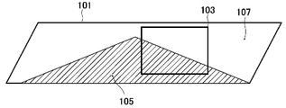
[도 2] VR 파노라마 영상(101)에 있어서의 타겟 에리어(103)를 설명하기 위한 도면이다.
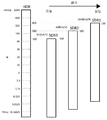
[도 3] 제1 다이나믹 레인지(HDR)와 제2 다이나믹 레인지(SDR)를 비교하여 나타내는 도면이다.
[도 4] VR 파노라마 영상(101)에 있어서 타겟 에리어(103)가 양달 부분에 있는 경우를 나타내는 도면이다.
[도 5] HDR로부터 SDR로의 다이나믹 레인지의 변환예를 나타내는 도면이다.
[도 6] VR 파노라마 영상(101)에 있어서 타겟 에리어(103)가 양달 부분과 응달 부분의 양방을 포함하는 경우를 나타내는 도면이다.
[도 7] 밝기의 대표값의 다른 계산 방법을 설명하기 위한 도면이다.
[도 8] HDR 영상 신호로부터 생성된 SDR 영상 신호에 대한 감마 처리의 감마 특성의 예를 나타내는 도면이다.
[도 9] 본 기술과 관련되는 변형예 2에 따른 영상 신호 처리 시스템(1A)의 구성을 나타내는 블럭도이다.
[도 10] 본 기술과 관련되는 변형예 3의 영상 신호 처리 시스템(1B)의 구성을 나타내는 블럭도이다.
[도 11] 도 10의 영상 신호 처리 시스템(1B)에 있어서의 배신 서버(30B)의 구성을 나타내는 블럭도이다.
[도 12] 도 12는 수술실 시스템 전체의 구성을 개략적으로 나타내는 도면이다.
[도 13] 도 13은 집중 조작 패널에 있어서의 조작 스크린의 표시예를 나타내는 도면이다.
[도 14] 도 14는 상기 수술실 시스템이 적용된 수술 상태의 일례를 나타내는 도면이다.
[도 15] 도 15는 도 14에 나타낸 CCU 및 카메라 헤드의 기능 구성의 일례를 나타내는 블럭도이다.
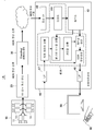
[도 16] 도 16은 집중 조작 패널에 있어서의 조작 스크린의 다른 표시예를 나타내는 도면이다. 1 is a block diagram showing the configuration of a video
FIG. 2 is a diagram for explaining the
FIG. 3 is a diagram illustrating a comparison of the first dynamic range HDR and the second dynamic range SDR. FIG.
FIG. 4 is a diagram illustrating a case where the
5 is a diagram illustrating an example of converting a dynamic range from HDR to SDR.
FIG. 6 is a diagram illustrating a case in which the
7 is a diagram for explaining another calculation method of representative values of brightness.
8 is a diagram illustrating an example of gamma characteristics of gamma processing for an SDR video signal generated from an HDR video signal.
Fig. 9 is a block diagram showing the configuration of a video
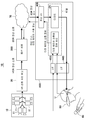
Fig. 10 is a block diagram showing the configuration of the video
FIG. 11 is a block diagram showing the configuration of a
12 is a diagram schematically showing the configuration of the entire operating room system.
FIG. 13 is a diagram illustrating a display example of an operation screen in the concentrated operation panel. FIG.
14 is a view showing an example of a surgical state to which the operating room system is applied.
FIG. 15 is a block diagram illustrating an example of a functional configuration of the CCU and the camera head shown in FIG. 14.
FIG. 16 is a diagram illustrating another display example of the operation screen in the concentrated operation panel.
이하, 본 기술과 관련되는 실시형태를, 도면을 참조하면서 설명한다.EMBODIMENT OF THE INVENTION Hereinafter, embodiment which concerns on this technology is described, referring drawings.
(영상 신호 처리 시스템)(Video signal processing system)
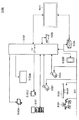
도 1은, 본 기술과 관련되는 제1 실시형태의 영상 신호 처리 시스템(1)의 구성을 나타내는 블럭도이다. 1 is a block diagram showing the configuration of a video
본 실시형태의 영상 신호 처리 시스템(1)은, 촬상 유닛(10)과, VR 신호 처리 유닛(20)과, 인코드/배신 유닛(30)과, 정보처리장치(40)와, 헤드 마운트 디스플레이(이하,「HMD」라 부른다.)(50)와, HMD용 콘트롤러(60)를 갖는다. VR은 Virtual Reality(가상 현실)의 약어이다.The video
(촬상 유닛(10))(Imaging unit 10)
촬상 유닛(10)은, 비교적 넓은, 예를 들면 HDR 등의 제1 다이나믹 레인지로 촬상을 행할 수 있는 1대 이상의 카메라(11)를 포함한다. 본 실시형태에서는, 예를 들면, HMD(50)에 360도 파노라마 영상을 VR 영상으로서 표시시키기 위해, 복수의 카메라(11)를 포함한 촬상 유닛(10)이 이용된다. 촬상 유닛(10)의 복수의 카메라(11)에 의해 각각 촬상된 복수의 HDR 영상 신호는, 도시하지 않은 전송 인터페이스에 의해 VR 신호 처리 유닛(20)에 전송된다.The
(VR 신호 처리 유닛(20)) (VR signal processing unit 20)
VR 신호 처리 유닛(20)은, 예를 들면, CPU(Central Processing Unit), 메모리, 전송 인터페이스 등을 포함한다. VR 신호 처리 유닛(20)의 CPU는, 촬상 유닛(10)으로부터 전송된 복수의 HDR 영상 신호를 수신하고, 메모리를 이용하여 이들 복수의 HDR 영상 신호를 공간적으로 결합하는 스티칭이나, 렌즈 왜곡 보정 등을 행하고, 예를 들면 360도 파노라마 영상 등의 VR 영상을 생성하고, 당해 VR 영상을 전송 인터페이스를 사용하여 인코드/배신 유닛(30)에 공급한다.The VR
(인코드/배신 유닛(30)) (Encode / Delivery Unit 30)
인코드/배신 유닛(30)은, 예를 들면, CPU, 메모리, 전송 인터페이스, 통신 인터페이스 등을 포함한다. 인코드/배신 유닛(30)은, 정보처리장치(40)로부터의 VR 영상의 배신 요구에 응답하여, 전송 인터페이스를 사용하여 VR 신호 처리 유닛(20)으로부터 취득한 VR 영상의 HDR 영상 신호를 네트워크 전송에 적합한 형식의 데이터로 부호화 하고, 통신 인터페이스를 사용하여, 배신 요구원의 정보처리장치(40)에 인터넷 등의 네트워크(70)를 통해 배신한다. The encode /
(정보처리장치(40))(Information processing device 40)
정보처리장치(40)는, 인코드/배신 유닛(30)에 VR 영상의 배신 요구를 송신하고, 이 요구에 응답하여 인코드/배신 유닛(30)으로부터 배신된 VR 영상의 HDR 영상 신호를 수신하고, 수신한 HDR 영상 신호로부터 HMD(50)에 공급하여 표시시키기 위한 SDR 영상 신호를 생성한다.The
정보처리장치(40)는, CPU(41)와, 메모리(42)와, 네트워크(70)와의 통신 인터페이스(43)와, HMD(50)와의 통신 인터페이스(44)와, HMD용 콘트롤러(60)와의 통신 인터페이스(45)를 포함한다. The
메모리(42)는, CPU(41)에 실행시키는 오퍼레이팅 시스템 및 애플리케이션 프로그램을 보관한다. 또한, 메모리(42)는, CPU(41)의 연산 처리를 위한 작업 영역, 인코드/배신 유닛(30)으로부터 배신된 HDR 영상 신호의 일시 보존 영역 등을 제공한다. The
네트워크(70)와의 통신 인터페이스(43)는, 네트워크(70)를 통해 인코드/배신 유닛(30)에 VR 영상의 배신 요구를 송신하거나 이 배신 요구에 응답하여 인코드/배신 유닛(30)으로부터 배신된 VR 영상의 HDR 영상 신호를 수신하기 위해 이용된다. 네트워크(70)와의 통신 인터페이스(43)는, 무선 LAN(Local Area Network) 대응의 장치여도 되고, 유선에 의한 통신을 행하는 유선 통신 장치여도 된다. 또한, 네트워크(70)를 통해 인코드/배신 유닛(30)으로부터 VR 영상의 배신을 받는 방법 이외에, 광디스크와 같은 물리 미디어를 통해, 정보처리장치(40)가 VR 영상을 취득해도 된다. 이 경우에는, 정보처리장치(40)는 물리 미디어를 착탈 가능한 드라이브 장치와 같은 미디어 인터페이스를 사용하여 물리 미디어로부터 VR 영상을 읽어들이도록 구성하면 된다. The
HMD(50)와의 통신 인터페이스(44)는, 정보처리장치(40)로부터 HMD(50)로의 SDR 영상 신호의 전송이나, HMD(50) 내의 자이로 센서, 가속도 센서 및 카메라 등의 센서의 검출 신호의 취득 등에 이용된다. HMD(50)와의 통신 인터페이스(44)에는, 예를 들면, HDMI(High-Definition Multimedia Interface)(등록상표), USB(Universal Serial Bus), 이들의 조합 등이 이용된다. 혹은, Bluetooth(등록상표) 등의 근거리 무선 통신이나, Wi-Fi(등록상표) 등의 무선 LAN 등을 이용해도 된다.The
HMD용 콘트롤러(60)와의 통신 인터페이스(45)는, HMD용 콘트롤러(60)로부터의 줌인/줌아웃의 조작 신호나 선택/결정 버튼의 조작에 대응하는 조작 신호의 취득 등에 이용되는 인터페이스이다. HMD용 콘트롤러(60)와의 통신 인터페이스(45)는, 예를 들면, Bluetooth(등록상표) 등의 근거리 무선 통신이나, Wi-Fi(등록상표) 등의 무선 LAN, 와이어리스 USB(Universal Serial Bus) 등이어도 된다.The
정보처리장치(40)의 CPU(41)는, 네트워크(70)와의 통신 인터페이스(43)를 이용하여, 인코드/배신 유닛(30)으로부터 배신된 VR 영상의 HDR 영상 신호를 수신하고, 수신된 HDR 영상 신호를 디코드한다. 또한, CPU(41)는, HMD(50)와의 통신 인터페이스(44)를 이용하여, HMD(50) 내의 자이로 센서 및 가속도 센서 등의 센서의 검출 신호를 취득하고, 취득한 검출 신호로부터 HMD(50)를 장착하고 있는 유저(U)의 VR 공간 내의 시선 방향(방위각, 자세각)을 검출하고, 이 시선 방향에 있는, HMD(50)의 디스플레이 해상도분의 영역(표시 에리어)에 있어서의 중앙 부분의 임의 사이즈의 영역을 타겟 에리어로서 산출한다. The
정보처리장치(40)의 CPU(41)는, 타겟 에리어를 산출하면, 메모리(42)에 보존된 HDR 영상 신호를 토대로 타겟 에리어의 HDR 영상 신호의 밝기의 대표값를 산출한다. 정보처리장치(40)의 CPU(41)는, 이 밝기의 대표값에 기초하여 부의 게인값을 결정하고, 이 부의 게인값을 HDR 영상 신호에 승산함으로써 HDR 영상 신호의 다이나믹 레인지를 압축하고, 그 다이나믹 레인지를 SDR 등의 제2 다이나믹 레인지에 더욱 제한하여 SDR 영상 신호를 생성한다. 정보처리장치(40)의 CPU(41)는, 생성한 SDR 영상 신호를 HMD(50)와의 통신 인터페이스(44)를 이용하여 HMD(50)에 공급하도록 제어를 행한다.When the
(HMD(50))(HMD (50))
HMD(50)는, 디스플레이와, 자이로 센서와, 가속도 센서와, 정보처리장치(40)와의 통신 인터페이스와, HMD용 콘트롤러(60)와의 통신 인터페이스를 포함한다.The
디스플레이는, VR 신호 처리 유닛(20)에 의해 생성되는 VR 파노라마 영상을 표시할 수 있는 디스플레이이다.The display is a display capable of displaying a VR panoramic image generated by the VR
HMD(50)에 제공된 자이로 센서 및 가속도 센서의 각각의 검출 신호는, 정보처리장치(40)와의 통신 인터페이스를 이용하여 정보처리장치(40)에 송신된다. The detection signals of the gyro sensor and the acceleration sensor provided to the
HMD용 콘트롤러(60)는, 예를 들면, CPU와, 메모리와, 자이로 센서와, 가속도 센서와, 정보처리장치(40)와의 통신 인터페이스와, 선택/결정 버튼 등을 포함한다.The
HMD용 콘트롤러(60)의 CPU는, 유저(U)가 HMD용 콘트롤러(60)를 공간적으로 움직였을 때에 자이로 센서나 가속도 센서 등이 발생시키는 검출 신호나 선택/결정 버튼의 조작 신호를, 통신 인터페이스를 이용하여 정보처리장치(40)에 송신한다.The CPU of the
정보처리장치(40)의 CPU(41)는, HMD(50)에 표시시키는 VR 영상에 유저(U)의 조작 대상인 복수의 버튼 등의 복수의 오브젝트나, HMD용 콘트롤러(60)의 조작에 연동하는 커서 포인터 등을 VR 영상에 합성하여 표시한다. 복수의 오브젝트에 각각 할당되어진 기능에는, 예를 들면, HMD(50)에 표시시키는 VR 영상의 줌인, 줌아웃 등이 있다. 유저(U)는 HMD용 콘트롤러(60)의 조작에 의해 커서 포인터를, 목적하는 기능이 할당되어진 오브젝트의 위치로 이동시키고, HMD용 콘트롤러(60)에 설치된 선택/결정 버튼을 누름으로써, 정보처리장치(40)의 CPU에 의해 그 기능을 실행하기 위한 처리가 실행된다. The
또한, 정보처리장치(40)의 CPU(41)에 의한 타겟 에리어의 산출에 있어서는, 예를 들면, HMD(50)로부터 공급되는 자이로 센서 및 가속도 센서의 각각의 검출 신호 등에 더하여, HMD용 콘트롤러(60)로부터 공급되는 줌인, 줌아웃의 조작 신호도 이용된다. 즉, 정보처리장치(40)의 CPU(41)는, HMD용 콘트롤러(60)로부터 공급되는 줌인, 줌아웃의 조작 신호를 토대로 타겟 에리어를 재계산한다. In the calculation of the target area by the
또한, 타겟 에리어의 다른 산출 방법으로서는, 외부의 레이저 이미터로부터 조사된 적외선을 HMD(50)에 부착된 복수의 적외선 센서에 의해 수광하고 그 출력 신호를 분석하여 HMD(50)의 위치나 방향을 산출하고, 이 산출 결과로부터 타겟 에리어를 산출하는 방법 등이 있다. 혹은, 외부의 적외선 카메라 등에 의해 HMD(50)에 부착된 LED 등의 광원으로부터의 광을 촬영하고, 촬영된 화상을 분석하여 HMD(50)의 위치나 방향을 산출하고, 이 산출 결과로부터 타겟 에리어를 산출하도록 해도 된다. In addition, as another method of calculating the target area, infrared rays irradiated from an external laser emitter are received by a plurality of infrared sensors attached to the
(타겟 에리어의 영상의 밝기에 관해)(About brightness of image of target area)
도 2는, VR 파노라마 영상(101)에 있어서의 타겟 에리어(103)를 설명하기 위한 도면이다. FIG. 2 is a diagram for describing the
이 도 2에 있어, VR 파노라마 영상(101) 내의 사선으로 채워진 부분은 응달 부분의 영상(105), 그 외의 부분은 양달 부분의 영상(107)이다. 양달 부분의 영상(107)은 응달 부분의 영상(105)에 비해 전체적으로 밝다. 여기서, 사각형에 의해 둘러싸인 영역은 타겟 에리어(103)이다. 도 2의 예에서는, 타겟 에리어(103)의 영상의 대부분은 응달 부분의 영상(105)이다. In FIG. 2, the portion filled with diagonal lines in the VR
도 3은, 제1 다이나믹 레인지(HDR)와 제2 다이나믹 레인지(SDR)를 비교하여 나타내는 도면이다.3 is a diagram illustrating a comparison of the first dynamic range HDR and the second dynamic range SDR.
제2 다이나믹 레인지(SDR)를 100%로 하면, 제1 다이나믹 레인지(HDR)는 예를 들면 1300% 등, 제2 다이나믹 레인지(SDR)보다 넓다. 여기서, 제2 다이나믹 레인지(SDR)가 제1 다이나믹 레인지(HDR)의 0~100%의 레인지 부분에 대응할 경우, 도 2에 나타낸 응달 부분의 영상(105)처럼 전체적으로 어두운 부분의 영상을 제2 다이나믹 레인지(SDR)에 의해 표시시켜도, HDR 영상 신호의 콘트라스트와 SDR 영상 신호의 콘트라스트 사이에 큰 변화는 나타나지 않는다. 그러나, 예를 들면, 도 4에 나타내는 바와 같이, 타겟 에리어(103)의 영상의 대부분이 양달 부분의 영상(107)인 등 밝은 영상인 경우, 제2 다이나믹 레인지(SDR)에 의해 표시시킨 영상에 콘트라스트의 현저한 저하가 생기거나 밝은 부분이 날아가 버릴 우려가 있다. When the second dynamic range SDR is 100%, the first dynamic range HDR is wider than the second dynamic range SDR, for example, 1300%. Here, when the second dynamic range SDR corresponds to a range portion of 0 to 100% of the first dynamic range HDR, the second dynamic range is divided into a second dynamic image such as an
본 실시형태에서는, 이와 같은 과제를 해결하기 위해, 정보처리장치(40)의 CPU(41)가, 타겟 에리어의 HDR 영상 신호의 밝기의 대표값를 산출하고, 이 밝기의 대표값을 토대로 결정한 부의 게인값을 HDR 영상 신호에 승산함으로써 HDR 영상 신호의 다이나믹 레인지를 압축하고, 그 다이나믹 레인지를 더 제2 다이나믹 레인지(SDR)로 제한하여, SDR 영상 신호를 생성하도록 구성되어 있다.In this embodiment, in order to solve such a subject, the
(영상 신호 처리 시스템(1)의 동작)(Operation of the video signal processing system 1)
다음으로, 본 실시형태의 영상 신호 처리 시스템(1)의 동작을 설명한다.Next, the operation of the video
정보처리장치(40)의 CPU(41)는, 네트워크(70)와의 통신 인터페이스(43)를 이용하여, 인코드/배신 유닛(30)에 VR 영상의 배신 요구를 송신한다.The
인코드/배신 유닛(30)의 CPU는, 정보처리장치(40)로부터의 VR 영상의 배신 요구를 수신하면, VR 신호 처리 유닛(20)으로부터 전송된 VR 영상의 HDR 영상 신호를 네트워크 전송에 적합한 형식의 데이터로 부호화 하고, 그 데이터를 패킷화 하여, 네트워크(70)를 통해 정보처리장치(40)에 배신한다.When the CPU of the encode /
정보처리장치(40)의 CPU(41)는, 네트워크(70)를 통해 인코드/배신 유닛(30)으로부터 배신된 VR 영상의 HDR 영상 신호를 통신 인터페이스(43)를 사용하여 수신하고, 수신한 HDR 영상 신호를 디코드 하여, 그 디코드 된 신호를 메모리(42)에 보존한다.The
정보처리장치(40)의 CPU(41)는, HMD(50)로부터 자이로 센서 및 가속도 센서의 각각의 검출 신호를 취득하고, 각각의 검출 신호를 이용하여, HMD(50)를 장착하고 있는 유저(U)의 VR 공간 내의 시선 방향(방위각, 자세각)을 검출하고, 이 시선 방향에 있는, HMD(50)의 디스플레이 해상도분의 영역에 있어서의 중앙 부분의 임의 사이즈의 영역을 상기 타겟 에리어로서 산출한다. The
다음으로, 정보처리장치(40)의 CPU(41)는, 산출된 타겟 에리어의 HDR 영상 신호의 밝기의 대표값을 산출하고, 이 밝기의 대표값을 토대로 HDR 영상 신호에 승산하는 부의 게인값을 산출한다. 다음으로, 정보처리장치(40)의 CPU(41)는, 산출된 부의 게인값을 HDR 영상 신호에 승산함으로써 HDR 영상 신호의 다이나믹 레인지를 압축하고, 그 다이나믹 레인지를 더욱 제2 다이나믹 레인지(SDR)로 제한하여 SDR 영상 신호를 생성한다. 이 SDR 영상 신호의 생성에 대해서는 나중에 상세하게 설명한다.Next, the
다음으로, 정보처리장치(40)의 CPU(41)는, 생성된 SDR 영상 신호로부터 상기 타겟 에리어를 포함하는 영역의 SDR 영상 신호를 잘라내고, HMD(50)와의 통신 인터페이스(44)를 사용하여 그 타겟 에리어를 포함하는 영역의 SDR 영상 신호를 HMD(50)에 공급한다. Next, the
HMD(50)는, 정보처리장치(40)로부터 공급된 SDR 영상 신호를 수신하고, 수신된 SDR 영상 신호를 디스플레이에 표시시킨다. The
(HDR로부터 SDR로의 다이나믹 레인지의 변환)(Change of dynamic range from HDR to SDR)
여기서, HDR로부터 SDR로의 다이나믹 레인지의 변환에 대해 상세하게 설명한다.Here, the conversion of the dynamic range from HDR to SDR will be described in detail.
정보처리장치(40)의 CPU(41)는, 타겟 에리어의 HDR 영상 신호의 밝기의 대표값으로서, 예를 들면 휘도 평균값 등을 산출한다. 또한, 타겟 에리어의 HDR 영상 신호의 밝기의 대표값은 휘도 평균값에 한정되지 않는다. 그 외의 밝기의 대표값에 대해서는 나중에 설명한다. The
도 5는 HDR로부터 SDR로의 다이나믹 레인지의 변환예를 나타내는 도면이다.5 is a diagram illustrating an example of converting a dynamic range from HDR to SDR.
또한, 이 도 5에 있어서, 종축은 렌즈의 조임의 단수에 상당하는 Stop의 값으로 나타내지는 다이나믹 레인지를 나타낸다. 1Stop 증가할 때마다 다이나믹 레인지는 2배로 된다.In addition, in this FIG. 5, the vertical axis | shaft shows the dynamic range represented by the value of Stop corresponding to the number of steps of the tightening of a lens. For every stop, the dynamic range doubles.
예로서, 제1 다이나믹 레인지(HDR)의 레인지 길이는, 제2 다이나믹 레인지(SDR)의 레인지 길이의 약 13배로 한다.For example, the range length of the first dynamic range HDR is about 13 times the range length of the second dynamic range SDR.
우선, 도 4에 나타낸 것처럼, 타겟 에리어(103) 내의 영상의 대부분이 양달 부분의 영상(107)이기 때문에, 밝기의 대표값이 비교적 높을 경우에 대해 설명한다. First, as shown in FIG. 4, since the majority of the image in the
정보처리장치(40)의 CPU(41)는, 타겟 에리어 내의 HDR 영상 신호의 밝기의 대표값이 높을(밝을)수록, 절대값이 더 큰 부의 게인값을 HDR 영상 신호에 승산함으로써 HDR 영상 신호의 다이나믹 레인지를 높은 압축율로 압축한다. 예를 들면, HDR 영상 신호에 부의 게인값으로서 -12dB이 승산되었을 경우, 다이나믹 레인지가 압축된 영상 신호의 고휘도 부분(약 400%까지)이 다이나믹 레인지(SDR1) 내에 거의 들어간다. 이에 의해, HMD(50)의 디스플레이에 VR 영상 중의 밝은 부분의 영상이 표시되는 경우에, 콘트라스트의 현저한 저하의 발생이나 밝은 부분이 날아가 버리는 것을 가능한 한 억제할 수 있다.The
다음으로, 도 6에 나타내는 바와 같이, 타겟 에리어(103) 내의 영상에 양달 부분의 영상(107)과 응달 부분의 영상(105)이 혼재할 경우의 다이나믹 레인지의 변환예를 설명한다. 이 경우에는, 부의 게인값의 절대값을, 예를 들면 "12"보다 낮게 한다. 예를 들면, HDR 영상 신호에 부의 게인값으로서 -6dB이 승산되었을 경우를 나타내고 있다. 이 경우, 다이나믹 레인지가 압축된 영상 신호 중의 중 휘도 부분(약 200%) 이하가 다이나믹 레인지(SDR2) 내에 들어간다. Next, as shown in FIG. 6, the example of a conversion of the dynamic range when the
도 7은, 타겟 에리어 내에서 응달 부분의 영상이 차지하는 비율이 더욱 커졌을 경우의 다이나믹 레인지의 변환예이다. 이 경우에는, 부의 게인값의 절대값을 더욱 감소시킴으로써, 다이나믹 레인지가 압축된 영상 신호의 저휘도 부분(약 0%로부터 100%)이 다이나믹 레인지(SDR3) 내에 들어간다.7 shows an example of conversion of the dynamic range when the ratio of the video of the shaded portion in the target area becomes larger. In this case, by further reducing the absolute value of the negative gain value, the low luminance portion (about 0% to 100%) of the video signal in which the dynamic range is compressed is brought into the dynamic range SDR3.
이상과 같이, 본 실시형태에서는, 정보처리장치(40)의 CPU(41)가, 타겟 에리어 내의 HDR 영상 신호의 밝기의 대표값을 토대로, HDR 영상 신호에 승산되는 부의 게인값을 가변하고, 이 부의 게인값을 HDR 영상 신호에 승산함으로써 HDR 영상 신호의 다이나믹 레인지를 압축하고, 그 다이나믹 레인지를 더욱 제2 다이나믹 레인지(SDR)로 제한하여 SDR 영상 신호를 생성한다. 이에 의해, HDR 영상 신호로부터 생성되는 SDR 영상 신호를 HMD(50)에 표시시켰을 경우에 콘트라스트의 현저한 저하의 발생이나 밝은 부분이 날아가는 것을 가능한 한 억제할 수 있다. As described above, in the present embodiment, the
또한 HDR 영상 신호에 대해서 부의 게인값이 승산되어지기 전에 HDR 영상 신호에 대해 색역 변환이 이루어져도 된다. 예를 들면, HDR 영상 신호가 ITU-R BT.2020에 규정된 색역을 가지는 영상일 경우, ITU-R BT.709에 규정된 색역으로 변환하는 것 등을 들 수 있다.In addition, the gamut conversion may be performed on the HDR video signal before the negative gain value is multiplied with the HDR video signal. For example, when the HDR video signal is a video having a color gamut defined in ITU-R BT.2020, conversion to a color gamut defined in ITU-R BT.709 is mentioned.
<변형예 1><
(타겟 에리어의 밝기의 대표값의 산출 방법의 변형예)(Modification example of calculation method of representative value of brightness of target area)
상기 실시형태에서는, 타겟 에리어의 HDR 영상 신호의 평균 휘도의 값을 밝기의 대표값으로서 산출하였다. 그러나, 예를 들면, 도 7에 나타내는 바와 같이, 응달 부분과 양달 부분이 혼재할 경우에 타겟 에리어(103)의 중심 부분(123)과 그 외의 주연 부분(125) 사이에 가중을 변경하여 휘도 평균을 구해도 된다. 예를 들면, 타겟 에리어(103)의 중심 부분(123)의 각 화소의 휘도에 대해 계수 P를 승산하고 타겟 에리어(103)의 주연 부분(125)의 각 화소의 휘도에 대해 계수 P보다 값이 작은 계수 Q를 승산하여, 휘도 평균을 구하는 등의 방법이 있다. 유저의 시선은 타겟 에리어(103)의 중심에 있으므로, 이 방법에 의해, 보다 적절한 밝기의 대표값과 부의 게인값을 얻을 수 있다.In the said embodiment, the value of the average brightness of the HDR video signal of a target area was computed as a representative value of brightness. However, for example, as shown in FIG. 7, when the shaded portion and the moon portion are mixed, the weight average is changed between the
<변형예 2><
(SDR 영상 신호에 대한 감마 처리)(Gamma processing for SDR video signal)
타겟 에리어에 평균 휘도가 크게 다른 복수의 영역이 존재할 경우, 예를 들면, 도 6에 나타낸 것처럼, HDR 영상 신호에 부의 게인값이 승산되어짐에 의해 다이나믹 레인지가 압축된 영상 신호의 저휘도부와 중휘도부의 일부가 제2 다이나믹 레인지(SDR) 내에 들어간다. 그러나, 고휘도부가 제2 다이나믹 레인지(SDR)로부터 일탈하기 때문에, 고휘도부에 있어 밝은 부분의 날아감이 발생한다.When there are a plurality of regions where the average brightness is significantly different in the target area, for example, as shown in FIG. 6, the low luminance portion and the middle of the video signal having the dynamic range compressed by multiplying the negative gain value by the HDR video signal are multiplied. A portion of the luminance portion falls within the second dynamic range SDR. However, since the high brightness portion deviates from the second dynamic range SDR, the bright portion flies away in the high brightness portion.
따라서, 타겟 에리어에 평균 휘도가 크게 다른 복수의 영역이 존재할 경우에는, SDR 영상 신호를 생성할 때, 예를 들면, 도 8에 나타내는 바와 같이, 고휘도부를 저장하는 레인지를 증대시키도록 감마 처리를 실시하여도 된다.Therefore, when there are a plurality of regions where the average luminance is significantly different in the target area, when generating the SDR video signal, for example, as shown in FIG. 8, gamma processing is performed to increase the range for storing the high luminance portion. You may also do it.
또한, 타겟 에리어에 평균 휘도가 크게 다른 복수의 영역이 존재하는 것을 판정하기 위해, 정보처리장치(40)의 CPU(41)는 타겟 에리어의 HDR 영상 신호에 대해 휘도 히스토그램을 산출하고, 임계값을 사용하여, 평균 휘도가 크게 다른 복수의 영역의 존재 유무를 판정한다.In addition, in order to determine that there are a plurality of regions in which the average luminance is significantly different in the target area, the
<변형예 3><Modification 3>
(텔레비젼에의 응용)(Application to TV)
상기 실시형태에서는, HMD(50)에 표시시키는 SDR 영상 신호를 생성할 경우에 대해 설명하였다. 그러나, 본 기술은, 예를 들면 텔레비젼의 화면에 VR 파노라마 영상의 임의 부분을 표시시키는 경우에도 적용할 수 있다.In the above embodiment, the case where the SDR video signal to be displayed on the
도 9는, SDR 영상 신호를 표시하는 텔레비젼을 이용한 영상 신호 처리 시스템(1A)의 구성을 나타내는 블럭도이다.9 is a block diagram showing the configuration of a video
정보처리장치(40A)는, 텔레비젼(80)과의 통신 인터페이스(46) 및 TV용 콘트롤러(90)와의 통신 인터페이스(47)를 포함한다. 정보처리장치(40A)의 CPU(41A)는, TV용 콘트롤러(90)로부터 타겟 에리어를 이동시키기 위한 조작 신호나 줌인/줌아웃의 조작 신호를 수신하고, 타겟 에리어의 산출을 행한다. 계속해서 정보처리장치(40A)의 CPU(41A)는, 산출한 타겟 에리어의 HDR 영상 신호의 밝기의 대표값의 산출, 부의 게인값의 산출, HDR 영상 신호에의 부의 게인값의 승산을 행한다. 더 계속해서, 정보처리장치(40A)의 CPU(41A)는, 부의 게인값이 승산됨으로써 다이나믹 레인지가 압축된 영상 신호로부터 SDR 영상 신호를 생성하고, 생성된 SDR 영상 신호로부터 타겟 에리어를 포함하는 임의의 표시 에리어의 SDR 영상 신호를 잘라내고, 그 잘라낸 SDR 영상 신호를 텔레비젼(80)에 공급하도록 제어를 행한다.The information processing apparatus 40A includes a
본 기술은, 디스플레이를 포함하는 그 외의 기기에 응용될 수 있다. The present technology can be applied to other devices including a display.
예를 들면, 스마트 폰, 태블릿 단말 등의 기기의 디스플레이에 VR 파노라마 영상의 임의 부분을 표시시키는 경우에도 적용할 수 있다.For example, the present invention can be applied to a case where an arbitrary portion of a VR panoramic image is displayed on a display of a device such as a smartphone or a tablet terminal.
<변형예 4><
(서버에 의한 HDR 영상 신호로부터 SDR 영상 신호의 생성)(Generation of SDR video signal from HDR video signal by server)
본 기술은, 네트워크(70)에 접속된 서버에도 적용할 수 있다.The present technology can also be applied to a server connected to the
도 10은, HDR 영상 신호로부터, HMD(50)에 표시시키는 SDR 영상 신호를 배신 서버(30B)에 있어서 생성하는 영상 신호 처리 시스템(1B)의 구성을 나타내는 블럭도이다. 도 11은 배신 서버(30B)의 구성을 나타내는 블럭도이다.FIG. 10 is a block diagram showing the configuration of the video
이 도 11에 나타내는 바와 같이, 배신 서버(30B)는, 전형적인 컴퓨터의 하드웨어 구성을 갖는다. 배신 서버(30B)는, CPU(31B), 메모리(32B), VR 신호 처리 유닛(20)과의 통신 인터페이스(33B), 네트워크(70)와의 통신 인터페이스(34B)를 갖는다. As shown in FIG. 11, the
메모리(32B)는, CPU(31B)에 실행시키는 오퍼레이팅 시스템 및 애플리케이션 프로그램을 보관한다. 또한, 메모리(32B)는, CPU(31B)의 연산 처리를 위한 작업 영역, VR 신호 처리 유닛(20)으로부터 취득한 VR 영상의 HDR 영상 신호의 일시 보존 영역 등을 제공한다. The
VR 신호 처리 유닛(20)과의 통신 인터페이스(33B)는, VR 신호 처리 유닛(20)으로부터 VR 영상의 HDR 영상 신호를 수신하기 위해 이용된다.The
네트워크(70)와의 통신 인터페이스(34B)는, 네트워크(70)를 통해 정보처리장치(40B)로부터의 배신 요구나 타겟 에리어 산출용 정보의 수신, 정보처리장치(40B)로의 상기 표시 에리어의 SDR 영상 신호의 송신 등에 이용된다.The
CPU(31B)는, 네트워크(70)와의 통신 인터페이스(34B)를 이용하여, 정보처리장치(40B)로부터 송신된 VR 영상의 배신 요구를 수신하고, 그 VR 영상의 HDR 영상 신호로부터 표시 에리어의 SDR 영상 신호를 생성하고, 생성된 SDR 영상 신호를 정보처리장치(40B)에 송신한다. The
CPU(31B)는, 타겟 에리어를 산출하기 위해, 정보처리장치(40B)로부터 네트워크(70)를 통해 주기적으로 송신되어 오는 타겟 에리어 산출용 정보를 취득하고, 취득한 타겟 에리어 산출용 정보를 토대로 타겟 에리어를 산출하도록 제어를 행한다.In order to calculate the target area, the
또한, 배신 서버(30B)의 CPU(31B)는, 산출된 타겟 에리어의 HDR 영상 신호의 밝기의 대표값을 산출하고, 이 밝기의 대표값에 기초하여 HDR 영상 신호에 승산시키는 부의 게인값을 산출한다. 계속해서, 배신 서버(30B)의 CPU(31B)는, 산출된 부의 게인값을 HDR 영상 신호에 승산시킴으로써 당해 영상 신호의 다이나믹 레인지를 압축하고, 그 압축된 다이나믹 레인지를 더욱 제2 다이나믹 레인지(SDR)로 제한하여 SDR 영상 신호를 생성하도록 제어를 행한다.Further, the
또한, 배신 서버(30B)의 CPU(31B)는, 생성된 SDR 영상 신호로부터 상기 타겟 에리어를 포함하는 표시 사이즈분의 SDR 영상 신호(표시 에리어의 SDR 영상 신호)를, 네트워크(70)와의 통신 인터페이스(34B)를 이용하여, 정보처리장치(40B)에 송신하도록 제어를 행한다. Further, the
한편, 정보처리장치(40B)는, CPU(41B)와, 네트워크(70)와의 통신 인터페이스(43B)와, HMD(50)와의 통신 인터페이스(44B)와, HMD용 콘트롤러(60)와의 통신 인터페이스(45B), 및 도시하지 않은 메모리를 포함한다.On the other hand, the
메모리는, CPU(41B)에 실행시키는 오퍼레이팅 시스템 및 애플리케이션 프로그램을 보관한다. 또한, 메모리는, CPU(41B)의 연산 처리를 위한 작업 영역, 배신 서버(30B)로부터 전달된 SDR 영상 신호의 일시 보존 영역 등을 제공한다.The memory stores an operating system and an application program that are executed by the
네트워크(70)와의 통신 인터페이스(43B)는, 네트워크(70)를 통해서 배신 서버(30B)로의 VR 영상의 배신 요구나 타겟 에리어 산출용 정보의 송신, 배신 요구에 응답하여 배신 서버(30B)로부터 전달된 표시 에리어의 SDR 영상 신호의 수신에 이용된다. The
HMD(50)와의 통신 인터페이스(44B)는, 정보처리장치(40B)로부터 HMD(50)로의 SDR 영상 신호의 전송이나, HMD(50) 내의 자이로 센서 및 가속도 센서의 검출 신호의 취득 등에 이용된다. The
HMD용 콘트롤러(60)와의 통신 인터페이스(45B)는, HMD용 콘트롤러(60)로부터의 줌인/줌아웃의 조작 신호나 선택/결정 버튼의 조작에 대응하는 조작 신호의 취득 등에 이용되는 인터페이스이다. The
정보처리장치(40B)의 CPU(41B)는, 배신 서버(30B)에 VR 영상의 배신 요구를 송신하는 처리, 배신 서버(30B)로부터 네트워크(70)를 통해 전달된 SDR 영상 신호를 수신하고 디코드 하는 처리, 디코드한 SDR 영상 신호를 HMD(50)에 공급하는 처리, HMD(50)로부터 취득한 자이로 센서 및 가속도 센서의 각각의 검출 신호 및 HMD용 콘트롤러(60)로부터 취득한 줌인/줌아웃의 조작 신호 등을 타겟 에리어 산출용 정보로서 배신 서버(30B)에 송신하는 처리 등을 실시한다.The
HMD(50) 및 HMD용 콘트롤러(60)의 구성은, 제1 실시형태와 같기 때문에 설명을 생략한다.Since the configurations of the
(영상 신호 처리 시스템(1B)의 동작)(Operation of the video
다음으로, 본 변형예에 따른 영상 신호 처리 시스템(1B)의 동작을 설명한다.Next, the operation of the video
정보처리장치(40B)의 CPU(41B)는, 통신 인터페이스(43B)를 이용하여, 배신 서버(30B)에 VR 영상의 배신 요구를 네트워크(70)를 통해 송신한다.The
배신 서버(30B)의 CPU(31B)는, 정보처리장치(40B)로부터의 VR 영상의 배신 요구를 수신하면, VR 신호 처리 유닛(20)으로부터 전송된 VR 영상의 HDR 영상 신호를 메모리(32B)에 보관한다.When the
한편, 정보처리장치(40B)의 CPU(41B)는, HMD(50)로부터 자이로 센서 및 가속도 센서의 각각의 검출 신호를 취득하고, 그들 검출 신호를 타겟 에리어 산출용 정보로서 배신 서버(30B)에 통신 인터페이스(43B)를 사용하여 송신한다. 또한, 이 때, HMD용 콘트롤러(60)로부터 줌인/줌아웃의 조작 신호를 취득했을 경우에는, CPU(41B)는, 이 조작 신호도 타겟 에리어 산출용 정보로서 배신 서버(30B)에 통신 인터페이스(43B)를 사용하여 송신한다.On the other hand, the
배신 서버(30B)의 CPU(31B)는, 정보처리장치(40B)로부터의 타겟 에리어 산출용 정보를 수신하면, 이 타겟 에리어 산출용 정보를 토대로 타겟 에리어를 산출한다. 나아가, 배신 서버(30B)의 CPU(31B)는, 산출된 타겟 에리어의 HDR 영상 신호의 밝기의 대표값을 산출하고, 이 밝기의 대표값에 기초하여 HDR 영상 신호에 승산되는 부의 게인값을 산출한다. 다음으로, 배신 서버(30B)의 CPU(31B)는, 산출된 부의 게인값을 HDR 영상 신호에 승산시킴으로써 영상 신호의 다이나믹 레인지를 압축하고, 그 다이나믹 레인지를 더욱 제2 다이나믹 레인지(SDR)로 제한하여 SDR 영상 신호로서 영상 신호를 생성한다. 이어서, 배신 서버(30B)의 CPU(31B)는, 생성된 SDR 영상 신호로부터 상기 타겟 에리어를 포함하는 표시 사이즈분의 SDR 영상 신호(표시 에리어의 SDR 영상 신호)를 네트워크 전송에 적합한 데이터로 인코드 하고, 그 데이터를 패킷화 하며, 이 패킷화된 데이터를 네트워크(70)를 통해 정보처리장치(40)에 전달한다.When the
정보처리장치(40B)의 CPU(41B)는, 배신 서버(30B)로부터 SDR 영상 신호를 수신하고, 수신된 신호를 디코드 하고, HMD(50)와의 통신 인터페이스(44B)를 사용하여, SDR 영상 신호를 HMD(50)에 송신한다.The
HMD(50)의 CPU는, 정보처리장치(40)로부터 공급된 SDR 영상 신호를 수신하고, 수신된 SDR 영상 신호를 디스플레이에 표시시킨다.The CPU of the
<그 외의 변형예><Other modifications>
이상, 타겟 에리어의 산출을 위해, HMD(50)의 자이로 센서 및 가속도 센서의 검출 신호를 이용하였다. 그렇지만, VR 영상에 대한 유저의 시선 방향을 포착할 수 있다면, 검출 방법은 무엇으로 하더라도 상관없다. 예를 들면, 유저의 안구를 카메라로 촬영하여 시선 방향을 검출하거나 HMD용 콘트롤러(60)의 조작에 의해 VR 영상에 있어 보고 싶은 방향의 정보를 지정해도 된다. In the above, the detection signals of the gyro sensor and the acceleration sensor of the
<응용예><Application example>
본 개시와 관련되는 기술은, 다양한 제품에 응용할 수 있다. 예를 들면, 본 개시와 관련되는 기술은, 수술실 시스템에 적용되어도 된다. The technology according to the present disclosure can be applied to various products. For example, the technique according to the present disclosure may be applied to an operating room system.
도 12는, 본 개시와 관련되는 기술이 적용될 수 있는 수술실 시스템(5100)의 전체 구성을 개략적으로 나타내는 도면이다. 도 12를 참조하면, 수술실 시스템(5100)은, 수술실 내에 설치된 장치군이 시청각 컨트롤러(AV Controller)(5107) 및 수술실 제어 장치(5109)를 거쳐 서로 연계 가능도록 구성된다. 12 is a diagram schematically showing an overall configuration of an
수술실에는, 다양한 장치가 설치될 수 있다. 도 12에서는, 일례로서, 내시경 하 수술을 위한 각종의 장치군(5101)과, 수술실의 천정에 설치되어 수술자의 손을 촬상하는 천장(ceiling) 카메라(5187)와, 수술실의 천정에 설치되어 수술실 전체의 상태와 관련된 화상을 촬상하는 수술실 카메라(5189)와, 복수의 표시 장치(5103A ~ 5103D)와, 레코더(5105)와, 환자 베드(5183)와, 조명(5191)을 도시하고 있다. In the operating room, various devices may be installed. In FIG. 12, as an example,
여기서, 이들 장치 중, 장치군(5101)은, 후술하는 내시경 수술 시스템(5113)에 속하는 것이며, 내시경이나 당해 내시경에 의해 촬상된 화상을 표시하는 표시 장치 등으로 이루어진다. 내시경 수술 시스템(5113)에 속하는 여러 장치는 의료용 기기라고도 불려진다. 한편, 표시 장치(5103A ~ 5103D), 레코더(5105), 환자 베드(5183) 및 조명(5191)은, 내시경 수술 시스템(5113)과는 별개로, 예를 들면 수술실에 비치되어 있는 장치이다. 이들 내시경 수술 시스템(5113)에 속하지 않는 각 장치는 비의료용 기기라고도 불려진다. 시청각 컨트롤러(5107) 및/또는 수술실 제어 장치(5109)는, 이들 의료기기 및 비의료기기의 동작을 서로 연계하여 제어한다.Here, among these apparatuses, the
시청각 컨트롤러(5107)는, 의료기기 및 비의료기기에 있어서의 화상 표시에 관한 처리를, 통괄적으로 제어한다. 구체적으로는, 수술실 시스템(5100)이 구비하는 장치 중, 장치군(5101), 천장 카메라(5187) 및 수술실 카메라(5189)는, 수술 중에 표시해야 하는 정보(이하, 표시 정보라고도 한다)를 발신하는 기능을 포함하는 장치(이하, 발신원 장치라고도 한다)일 수 있다. 또한, 표시 장치(5103A ~ 5103D)는, 표시 정보가 출력되는 장치(이하, 출력처 장치라고도 한다)일 수 있다. 또한, 레코더(5105)는, 발신원 장치 및 출력처 장치의 쌍방에 해당하는 장치일 수 있다. 시청각 컨트롤러(5107)는, 발신원 장치 및 출력처 장치의 동작을 제어하고, 발신원 장치로부터 표시 정보를 취득함과 함께, 당해 표시 정보를 출력처 장치에 송신하여, 표시 또는 기록시키는 기능을 가진다. 또한, 표시 정보란, 수술 중에 촬상된 각종의 화상이나, 수술에 관한 각종의 정보(예를 들면, 환자의 신체 정보나, 과거의 검사 결과, 수술 방식에 대한 정보 등) 등이다. The
구체적으로는, 시청각 컨트롤러(5107)에는, 장치군(5101)으로부터, 표시 정보로서, 내시경에 의해 촬상된 환자의 체강 내의 수술부의 화상에 대한 정보가 송신될 수 있다. 또한, 천장 카메라(5187)로부터, 표시 정보로서, 당해 천장 카메라(5187)에 의해 촬상된 수술자의 손 화상에 대한 정보가 송신될 수 있다. 또한, 수술실 카메라(5189)로부터, 표시 정보로서, 당해 수술실 카메라(5189)에 의해 촬상된 수술실 전체의 상태와 관련된 화상에 대한 정보가 송신될 수 있다. 또한, 수술실 시스템(5100)에 촬상 기능을 가지는 다른 장치가 존재하는 경우에는, 시청각 컨트롤러(5107)는, 표시 정보로서, 당해 다른 장치로부터도 당해 다른 장치에 의해 촬상된 화상에 대한 정보를 취득해도 된다. Specifically, the
또는, 예를 들면, 레코더(5105)에는, 과거에 촬상된 이들 화상에 대한 정보가 시청각 컨트롤러(5107)에 의해 기록되고 있다. 시청각 컨트롤러(5107)는, 표시 정보로서, 레코더(5105)로부터 당해 과거에 촬상된 화상에 대한 정보를 취득할 수 있다. 또한, 레코더(5105)에는, 수술에 관한 각종의 정보도 사전에 기록되어 있어도 된다. Or, for example, in the
시청각 컨트롤러(5107)는, 출력처 장치인 표시 장치(5103A ~ 5103D) 중 적어도 어느 하나에, 취득한 표시 정보(즉, 수술 중에 촬영된 화상이나, 수술에 관한 각종의 정보)를 표시시킨다. 도시하는 예에서는, 표시 장치(5103A)는 수술실의 천정으로부터 매달려 설치되는 표시 장치이며, 표시 장치(5103B)는 수술실의 벽면에 설치되는 표시 장치이며, 표시 장치(5103C)는 수술실 내의 탁상에 설치되는 표시 장치이고, 표시 장치(5103D)는 표시 기능을 가지는 모바일 기기(예를 들면, 태블릿 PC(Personal Computer))이다. The audio-
또한, 도 12에는 도시를 생략하고 있지만, 수술실 시스템(5100)에는, 수술실의 외부의 장치가 포함되어도 된다. 수술실 외부에 제공된 장치는, 예를 들면, 병원 내외에 구축된 네트워크에 접속되는 서버나, 의료 스탭이 사용하는 PC, 병원의 회의실에 설치되는 프로젝터 등일 수 있다. 이들 외부 장치가 병원 외에 있는 경우에는, 시청각 컨트롤러(5107)는, 원격 의료를 위해서, 원격 회의 시스템 등을 거쳐서, 다른 병원의 표시 장치에 표시 정보를 표시시킬 수도 있다. In addition, although illustration is abbreviate | omitted in FIG. 12, the apparatus of the
수술실 제어 장치(5109)는, 비의료기기에 있어서의 화상 표시에 관한 처리 이외의 처리를, 통괄적으로 제어한다. 예를 들면, 수술실 제어 장치(5109)는, 환자 베드(5183), 천장 카메라(5187), 수술실 카메라(5189) 및 조명(5191)의 구동을 제어한다. The operating
수술실 시스템(5100)에는, 집중 조작 패널(5111)이 설치되어 있어, 유저는, 당해 집중 조작 패널(5111)을 거쳐서, 시청각 컨트롤러(5107)에 대해서 화상 표시에 대한 지시를 주거나, 수술실 제어 장치(5109)에 대해서 비의료기기의 동작에 대한 지시를 줄 수 있다. 집중 조작 패널(5111)은, 표시 장치의 표시면 상에 터치 패널이 설치되도록 구성된다. The
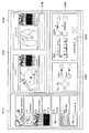
도 13은, 집중 조작 패널(5111)에 있어서의 조작 화면의 표시예를 나타내는 도면이다. 도 13에서는, 일례로서, 출력처 장치로서, 2개의 표시 장치가 설치되어 있는 경우에 대응하는 조작 화면을 나타내고 있다. 도 13을 참조하면, 조작 화면(5193)에는, 발신원 선택 영역(5195)과, 프리뷰 영역(5197)과, 컨트롤 영역(5201)이 설치된다. 13 is a diagram illustrating a display example of an operation screen in the
발신원 선택 영역(5195)에는, 수술실 시스템(5100)에 구비된 발신원 장치와, 당해 발신원 장치가 가지는 표시 정보를 나타내는 섬네일 화면이, 서로 연관되어 표시된다. 유저는, 표시 장치에 표시될 표시 정보를, 발신원 선택 영역(5195)에 표시되고 있는 임의의 발신원 장치로부터 선택할 수 있다. In the caller
프리뷰 영역(5197)에는, 출력처 장치인 2개의 표시 장치(Monitor 1, Monitor 2)에 표시되는 화면의 프리뷰가 표시된다. 도시하는 예에서는, 하나의 표시 장치에 있어서 4개의 화상이 PinP 표시되고 있다. 당해 4개의 화상은, 발신원 선택 영역(5195)에 있어서 선택된 발신원 장치로부터 발신된 표시 정보에 대응하는 것이다. 4개의 화상 중, 하나는 메인 화상으로서 비교적 크게 표시되고, 나머지 3개는 서브 화상으로서 비교적 작게 표시된다. 유저는, 4개의 화상이 표시된 영역을 적절하게 선택함으로써, 메인 화상과 서브 화상을 바꿔 넣을 수가 있다. 또한, 4개의 화상이 표시되는 영역의 아래에는, 스테이터스 표시 영역(5199)이 설치되고 있고, 당해 영역에 수술에 관한 스테이터스(예를 들면, 수술 경과시간이나, 환자의 신체 정보 등)가 적절하게 표시될 수 있다. In the
컨트롤 영역(5201)에는, 발신원의 장치에 대해서 조작을 행하기 위한 GUI(Graphical User Interface) 요소가 표시되는 발신원 조작 영역(5203)과, 출력처 장치에 대해서 조작을 행하기 위한 GUI 요소가 표시되는 출력처 조작 영역(5205)이 설치된다. 도시하는 예에서는, 발신원 조작 영역(5203)에는, 촬상 기능을 가지는 발신원 장치에 있어서의 카메라에 대해서 각종의 조작(팬, 틸트 및 줌)을 행하기 위한 GUI 요소가 마련되어 있다. 유저는, 이들 GUI 요소를 적절하게 선택함으로써, 발신원 장치에 있어서의 카메라의 동작을 조작할 수 있다. 또한, 도시는 생략하고 있지만, 발신원 선택 영역(5195)에 있어서 선택되어 있는 발신원 장치가 레코더일 경우(즉, 프리뷰 영역(5197)에 있어서, 레코더에 과거에 기록된 화상이 표시되고 있는 경우)에는, 발신원 조작 영역(5203)에는, 당해 화상의 재생, 재생 정지, 되감기, 빨리 감기 등의 조작을 행하기 위한 GUI 요소가 마련될 수 있다. In the
또한, 출력처 조작 영역(5205)에는, 출력처 장치인 표시 장치에 있어서의 표시에 대한 각종의 조작(스와프(swap), 플립(flip), 색조정, 콘트라스트 조정, 2D 표시와 3D 표시의 절환)을 행하기 위한 GUI 요소가 설치되어 있다. 유저는, 이들 GUI 요소를 적절하게 선택함으로써, 표시 장치에 있어서의 표시를 조작할 수 있다.Further, in the output
또한, 집중 조작 패널(5111)에 표시되는 조작 화면은 도시하는 예로 한정되지 않고, 유저는, 집중 조작 패널(5111)을 거쳐서, 수술실 시스템(5100)에 구비되는, 시청각 컨트롤러(5107) 및 수술실 제어 장치(5109)에 의해 제어될 수 있는 여러가지 장치에 대한 조작 입력이 가능해도 된다. In addition, the operation screen displayed on the
도 14는, 이상 설명한 수술실 시스템이 적용된 수술의 모습의 일례를 나타내는 도면이다. 천장 카메라(5187) 및 수술실 카메라(5189)는, 수술실의 천정에 설치되어, 환자 베드(5183) 상의 환자(5185)의 환부에 대해서 처치를 행하는 수술자(의사)(5181)의 손 및 수술실 전체의 모습을 촬영 가능하다. 천장 카메라(5187) 및 수술실 카메라(5189)에는, 배율 조정 기능, 초점 거리 조정 기능, 촬영 방향 조정 기능 등이 마련될 수 있다. 조명(5191)은, 수술실의 천정에 설치되어, 적어도 수술자(5181)의 손을 조사한다. 조명(5191)은, 그 조사 광량, 조사광의 파장(색) 및 광의 조사 방향 등을 적절하게 조정 가능하다. It is a figure which shows an example of the state of the surgery to which the operating room system demonstrated above was applied. The
내시경 수술 시스템(5113), 환자 베드(5183), 천장 카메라(5187), 수술실 카메라(5189) 및 조명(5191)은, 도 12에 나타내는 바와 같이, 시청각 컨트롤러(5107) 및 수술실 제어 장치(5109)(도 14에서는 도시하지 않음)를 거쳐서 서로 연계 가능하게 접속되어 있다. 수술실 내에는, 집중 조작 패널(5111)이 설치되어 있어, 상술한 바와 같이, 유저는, 당해 집중 조작 패널(5111)을 거쳐서, 수술실 내에 존재하는 이들 장치를 적절하게 조작하는 것이 가능하다. The
이하, 내시경 수술 시스템(5113)의 구성에 대해 상세하게 설명한다. 도시하는 바와 같이, 내시경 수술 시스템(5113)은, 내시경(5115)과, 그 외의 수술도구(5131)와, 내시경(5115)을 지지하는 지지 아암 장치(5141)와, 내시경 하 수술을 위한 각종의 장치가 탑재된 카트(5151)를 포함한다. Hereinafter, the configuration of the endoscope
내시경 수술에서는, 복벽을 갈라 개복하는 대신에, 투관침(trocars)(5139a ~ 5139d)로 불리는 통 형상의 개공 기구가 복벽에 복수 천자된다. 그리고, 투관침(5139a ~ 5139d)으로부터, 내시경(5115)의 경통(5117)이나, 그 외의 수술도구(5131)가 환자(5185)의 체강 내로 삽입된다. 도시하는 예에서는, 그 외의 수술도구(5131)로서, 기복튜브(5133), 에너지 처치구(5135) 및 겸자(5137)가, 환자(5185)의 체강 내로 삽입되고 있다. 또한, 에너지 처치구(5135)는, 고주파 전류나 초음파 진동에 의해, 조직의 절개 및 박리, 또는 혈관의 봉지 등을 행하는 처치구이다. 다만, 도시하는 수술도구(5131)는 어디까지나 일례이며, 수술도구(5131)로서는, 예를 들면 트위저(tweezers), 리트랙터(retractor) 등, 일반적으로 내시경 하 수술에 있어 사용되는 각종 수술도구가 사용되어도 된다. In endoscopic surgery, instead of splitting the abdominal wall and opening, a plurality of cylindrical openings called trocars (5139a to 5139d) are punctured into the abdominal wall. Then, from the trocars 5153a to 5139d, the
내시경(5115)에 의해 촬영된 환자(5185)의 체강 내의 수술부의 화상이, 표시 장치(5155)에 표시된다. 수술자(5181)는, 표시 장치(5155)에 표시된 수술부의 화상을 리얼타임으로 보면서, 에너지 처치구(5135)나 겸자(5137)를 사용하여, 예를 들면 환부를 절제하는 등의 처치를 행한다. 또한, 도시는 생략하고 있지만, 기복튜브(5133), 에너지 처치구(5135) 및 겸자(5137)는, 수술 중에, 수술자(5181) 또는 조수 등에 의해 지지된다. An image of the surgical part in the body cavity of the patient 5185 taken by the
(지지 아암 장치) (Support arm device)
지지 아암 장치(5141)는, 베이스부(5143)로부터 연장되는 아암부(5145)를 구비한다. 도시하는 예에서는, 아암부(5145)는, 관절부(5147a, 5147b, 5147c) 및 링크(5149a, 5149b)로 구성되어 있고, 아암 제어 장치(5159)로부터의 제어에 의해 구동된다. 아암부(5145)에 의해 내시경(5115)이 지지되고, 그 위치 및 자세가 제어된다. 이에 의해, 내시경(5115)의 안정적인 위치의 고정이 실현될 수 있다. The
(내시경) (Endoscope)
내시경(5115)은, 선단으로부터 소정 길이의 영역이 환자(5185)의 체강 내로 삽입되는 경통(5117)과, 경통(5117)의 기단에 접속되는 카메라 헤드(5119)로 구성된다. 도시하는 예에서는, 경성의 경통(5117)을 가지는 이른바 경성경으로서 구성되는 내시경(5115)을 도시하고 있지만, 내시경(5115)은, 연성의 경통(5117)을 가지는 이른바 연성경으로서 구성되어도 된다. The
경통(5117)의 선단에는, 대물렌즈가 끼워맞춰진 개구부가 설치되어 있다. 내시경(5115)에는 광원 장치(5157)가 접속되어 있고, 당해 광원 장치(5157)에 의해 생성된 광이, 경통(5117)의 내부에 연장하여 설치되는, 라이트 가이드에 의해 당해 경통(5117)의 선단까지 도광되어, 대물렌즈를 거쳐서 환자(5185)의 체강 내의 관찰 대상을 향하여 조사된다. 또한, 내시경(5115)은, 직시경이어도 되고, 사시경 또는 측시경이어도 된다. At the tip of the
카메라 헤드(5119)의 내부에는 광학계 및 촬상 소자가 설치되어 있고, 관찰 대상으로부터의 반사광(관찰광)은 당해 광학계에 의해 당해 촬상 소자에 집광된다. 당해 촬상 소자에 의해 관찰광이 광전 변환되어, 관찰광에 대응하는 전기 신호, 즉 관찰상에 대응하는 화상 신호가 생성된다. 당해 화상 신호는, RAW 데이터로서 카메라 컨트롤 유닛(CCU:Camera Control Unit)(5153)에 송신된다. 또한, 카메라 헤드(5119)에는, 그 광학계를 적절하게 구동시킴으로써, 배율 및 초점거리를 조정하는 기능이 탑재된다. An optical system and an imaging device are provided inside the
또한, 예를 들면 입체시(3D 표시) 등에 대응하기 위해서, 카메라 헤드(5119)에는 촬상 소자가 복수 설치되어도 된다. 이 경우, 경통(5117)의 내부에는, 당해 복수의 촬상 소자의 각각에 관찰광을 도광하기 위해서, 릴레이 광학계가 복수 계통 설치된다. In addition, for example, in order to cope with stereoscopic vision (3D display) or the like, a plurality of imaging elements may be provided in the
(카트에 탑재되는 각종의 장치) (Various devices mounted on the cart)
CCU(5153)는, CPU(Central Processing Unit)나 GPU(Graphics Processing Unit) 등에 의해 구성되며, 내시경(5115) 및 표시 장치(5155)의 동작을 통괄적으로 제어한다. 구체적으로는, CCU(5153)는, 카메라 헤드(5119)로부터 수취한 화상 신호에 대해서, 예를 들면 현상 처리(디모자이크 처리) 등의, 당해 화상 신호에 기초하는 화상을 표시하기 위한 각종의 화상 처리를 실시한다. CCU(5153)는, 당해 화상 처리를 실시한 화상 신호를 표시 장치(5155)에 제공한다. 또한, CCU(5153)에는, 도 12에 나타내는 시청각 컨트롤러(5107)가 접속된다. CCU(5153)는, 화상 처리를 실시한 화상 신호를 시청각 컨트롤러(5107)에도 제공한다. 또한, CCU(5153)는, 카메라 헤드(5119)에 대해서 제어 신호를 송신하여, 그 구동을 제어한다. 당해 제어 신호에는, 배율이나 초점거리 등, 촬상 조건에 관한 정보가 포함될 수 있다. 당해 촬상 조건에 관한 정보는, 입력장치(5161)를 거쳐서 입력되어도 되고, 상술한 집중 조작 패널(5111)을 거쳐 입력되어도 된다. The CCU 5503 is configured by a CPU (Central_Processing-Unit), a GPU (Graphics-Processing-Unit), or the like, and collectively controls the operations of the
표시 장치(5155)는, CCU(5153)로부터의 제어 하에, 당해 CCU(5153)에 의해 화상 처리가 실시된 화상 신호에 기초하는 화상을 표시한다. 내시경(5115)이 예를 들면 4K(수평 화소수 3840×수직 화소수 2160) 또는 8K(수평 화소수 7680×수직 화소수 4320) 등의 고해상도의 촬영을 지원하는 것일 경우, 및/또는 3D 표시를 지원하는 것일 경우에는, 표시 장치(5155)로서는, 각각에 대응하여, 고해상도의 표시가 가능한 것, 및/또는 3D 표시 가능한 것이 이용될 수 있다. 4K 또는 8K 등의 고해상도의 촬영에 대응한 것일 경우, 표시 장치(5155)로서 55인치 이상의 사이즈의 표시 장치를 이용함으로써 한층 더 몰입감을 얻을 수 있다. 또한, 용도에 따라, 해상도, 사이즈가 다른 복수의 표시 장치(5155)가 설치되어도 된다. The
광원 장치(5157)는, 예를 들면 LED(Light Emitting Diode) 등의 광원으로 구성되고, 수술부를 촬영할 때의 조사광을 내시경(5115)에 공급한다. The
아암 제어 장치(5159)는, 예를 들면 CPU 등의 프로세서를 포함하고, 소정의 프로그램에 따라 동작함으로써, 소정의 제어 방식에 따라 지지 아암 장치(5141)의 아암부(5145)의 구동을 제어한다. The
입력 장치(5161)는, 내시경 수술 시스템(5113)에 대한 입력 인터페이스이다. 유저는, 입력 장치(5161)를 거쳐서, 내시경 수술 시스템(5113)에 대해서 각종의 정보의 입력이나 지시의 입력을 행할 수 있다. 예를 들면, 유저는, 입력 장치(5161)를 거쳐서, 환자의 신체 정보나, 수술의 수술 방식에 대한 정보 등, 수술에 관한 각종의 정보를 입력한다. 또한, 예를 들면, 유저는, 입력 장치(5161)를 거쳐서, 아암부(5145)를 구동시키는 취지의 지시나, 내시경(5115)에 의한 촬상 조건(조사광의 종류, 배율 및 초점 거리 등)을 변경하는 취지의 지시, 에너지 처치구(5135)를 구동시키는 취지의 지시 등을 입력한다. The
입력 장치(5161)의 종류는 한정되지 않으며, 입력 장치(5161)는 각종의 공지의 입력 장치여도 된다. 입력 장치(5161)로서는, 예를 들면, 마우스, 키보드, 터치 패널, 스위치, 풋 스위치(5171) 및/또는 레버 등이 적용될 수 있다. 입력 장치(5161)로서 터치 패널이 사용될 경우에는, 당해 터치 패널은 표시 장치(5155)의 표시면 상에 설치되어도 된다. The type of the
또는, 입력장치(5161)는, 예를 들면 안경형의 웨어러블 디스플레이나 HMD(Head Mounted Display) 등의, 유저가 착용하는 디바이스이며, 이 디바이스에 의해 검출되는 유저의 제스처나 시선에 따라 각종의 입력이 이루어진다. 또한, 입력 장치(5161)는, 유저의 움직임을 검출 가능한 카메라를 포함하고, 당해 카메라에 의해 촬상된 영상으로부터 검출되는 유저의 제스처나 시선에 따라 각종의 입력이 이루어진다. 나아가, 입력 장치(5161)는, 유저의 소리를 수음 가능한 마이크로폰을 포함하고, 당해 마이크로폰을 거쳐서 음성에 의해 각종의 입력이 이루어진다. 이와 같이, 입력장치(5161)가 비접촉으로 각종의 정보를 입력 가능하게 구성됨으로써, 특히 청결 영역에 속하는 유저(예를 들면 수술자(5181))가, 불결 영역에 속하는 기기를 비접촉으로 조작하는 것이 가능해진다. 또한, 유저는, 소지하고 있는 수술 도구로부터 손을 떼지 않고 기기를 조작하는 것이 가능해지기 때문에, 유저의 편리성이 향상된다. Alternatively, the
처치구 제어 장치(5163)는, 조직의 소작, 절개 또는 혈관의 봉지 등을 위한 에너지 처치구(5135)의 구동을 제어한다. 기복 장치(5165)는, 내시경(5115)의 시야의 확보 및 수술자의 작업 공간의 확보를 목적으로, 환자(5185)의 체강을 부풀리기 위해서, 기복 튜브(5133)를 거쳐 당해 체강 내로 가스를 보낸다. 레코더(5167)는, 수술에 관한 각종의 정보를 기록 가능한 장치이다. 프린터(5169)는, 수술에 관한 각종의 정보를, 텍스트, 화상 또는 그래프 등 각종의 형식으로 인쇄 가능한 장치이다. The treatment instrument control device 5603 controls driving of the
이하, 내시경 수술 시스템(5113)에 있어서 특히 특징적인 구성에 대해, 보다 상세하게 설명한다. Hereinafter, the characteristic feature of the endoscope
(지지 아암 장치) (Support arm device)
지지 아암 장치(5141)는, 기대인 베이스부(5143)와, 베이스부(5143)로부터 연장되는 아암부(5145)를 구비한다. 도시하는 예에서는, 아암부(5145)는, 복수의 관절부(5147a, 5147b, 5147c)와, 관절부(5147b)에 의해 연결되는 복수의 링크(5149a, 5149b)로 구성되어 있지만, 도 14에서는, 간명화를 위해, 아암부(5145)의 구성을 간략화하여 도시하고 있다. 실제로는, 아암부(5145)가 소망하는 자유도를 가지도록, 관절부(5147a ~ 5147c) 및 링크(5149a, 5149b)의 형상, 수 및 배치, 그리고 관절부(5147a ~ 5147c)의 회전축의 방향 등이 적절하게 설정될 수 있다. 예를 들면, 아암부(5145)는, 바람직하게는, 6 자유도 이상의 자유도를 가지도록 구성될 수 있다. 이에 의해, 아암부(5145)의 가동 범위 내에서 내시경(5115)을 자유롭게 이동시키는 것이 가능하게 되기 때문에, 소망하는 방향으로부터 내시경(5115)의 경통(5117)을 환자(5185)의 체강 내로 삽입하는 것이 가능하게 된다. The
관절부(5147a ~ 5147c)에는 액추에이터가 설치되어 있고, 관절부(5147a ~ 5147c)는 당해 액추에이터의 구동에 의해 소정의 회전축 주위에 회전 가능하게 구성되어 있다. 당해 액추에이터의 구동이 아암 제어 장치(5159)에 의해 제어됨으로써, 각 관절부(5147a ~ 5147c)의 회전 각도가 제어되어, 아암부(5145)의 구동이 제어된다. 이에 의해, 내시경(5115)의 위치 및 자세의 제어가 실현될 수 있다. 이 때, 아암 제어 장치(5159)는, 힘 제어 또는 위치 제어 등, 각종 공지의 제어 방식에 의해 아암부(5145)의 구동을 제어할 수 있다. An actuator is provided in the
예를 들면, 수술자(5181)가, 입력 장치(5161)(풋 스위치(5171)를 포함한다)를 거쳐서 적절하게 조작 입력을 행함으로써, 당해 조작 입력에 따라 아암 제어 장치(5159)에 의해 아암부(5145)의 구동이 적절하게 제어되고, 내시경(5115)의 위치 및 자세가 제어되어도 된다. 당해 제어에 의해, 아암부(5145)의 선단의 내시경(5115)을 임의의 위치로부터 임의의 위치까지 이동시킨 후, 그 이동 후의 위치에서 고정적으로 지지할 수 있다. 또한, 아암부(5145)는, 이른바 마스터 슬레이브 방식으로 조작되어도 된다. 이 경우, 아암부(5145)는, 수술실로부터 떨어진 장소에 설치되는 입력장치(5161)를 거쳐 유저에 의해 원격 조작될 수 있다. For example, when the operator 5801 performs an operation input appropriately through the input device 5151 (including the foot switch 5171), the arm part by the
또한, 힘 제어가 적용될 경우에는, 아암 제어 장치(5159)는, 유저로부터의 외력을 받았을 때, 그 외력을 쫓아 스무드하게 아암부(5145)가 이동하도록, 각 관절부(5147a ~ 5147c)의 액추에이터를 구동시키는, 이른바 파워 어시스트 제어를 행해도 된다. 이에 의해, 유저가 직접 아암부(5145)에 접촉하면서 아암부(5145)를 이동시킬 때에, 비교적 작은 힘으로 당해 아암부(5145)를 이동시킬 수 있다. 따라서, 보다 직감적으로, 그리고 보다 간단하고 쉬운 조작으로 내시경(5115)을 이동시키는 것이 가능하여, 유저의 편리성을 향상시킬 수 있다. In addition, when force control is applied, the
여기서, 일반적으로, 내시경 하 수술에서는, 스코피스트(Scopist)라 불리는 의사에 의해 내시경(5115)이 지지되고 있었다. 이에 반해서, 지지 아암 장치(5141)를 이용함으로써, 사람의 손에 의하지 않고 내시경(5115)의 위치를 보다 확실하게 고정하는 것이 가능하게 되기 때문에, 수술부의 화상을 안정적으로 얻을 수 있어, 수술을 원활하게 행하는 것이 가능하게 된다. Here, generally, in the endoscopy operation, the
또한, 아암 제어 장치(5159)는 반드시 카트(5151)에 설치되지 않아도 된다. 또한, 아암 제어 장치(5159)는 반드시 하나의 장치가 아니어도 된다. 예를 들면, 아암 제어 장치(5159)는, 지지 아암 장치(5141)의 아암부(5145)의 각 관절부(5147a ~ 5147c)에 각각 설치되어도 되고, 복수의 아암 제어 장치(5159)가 서로 협동함으로써, 아암부(5145)의 구동 제어가 실현되어도 된다. In addition, the
(광원 장치) (Light source device)
광원 장치(5157)는, 내시경(5115)에 수술부를 촬영할 때의 조사광을 공급한다. 광원 장치(5157)는, 예를 들면 LED, 레이저 광원 또는 이들 조합에 의해 구성되는 백색 광원을 포함한다. 이 때, RGB 레이저 광원의 조합에 의해 백색 광원이 구성되는 경우에는, 각 색(각 파장)의 출력 강도 및 출력 타이밍을 고정밀도로 제어할 수 있기 때문에, 광원 장치(5157)에 있어서 촬상 화상의 화이트 밸런스의 조정을 행할 수 있다. 또한, 이 경우에는, RGB 레이저 광원 각각으로부터의 레이저 광을 시분할로 관찰 대상에 조사하고, 그 조사 타이밍에 동기하여 카메라 헤드(5119)의 촬상 소자의 구동을 제어함으로써, RGB 각각에 대응한 화상을 시분할로 촬상하는 것도 가능하다. 당해 방법에 의하면, 당해 촬상 소자에 컬러 필터를 설치하지 않아도, 컬러 화상을 얻을 수 있다. The
또한, 광원 장치(5157)는, 출력하는 광의 강도를 소정의 시간마다 변경하도록 그 구동이 제어되어도 된다. 그 광의 강도의 변경의 타이밍에 동기하여 카메라 헤드(5119)의 촬상 소자의 구동을 제어하고 시분할로 화상을 취득하고, 그 화상을 합성함으로써, 이른바 노출 부족이나 노출 과다가 없는 고다이나믹 레인지의 화상을 생성할 수 있다. In addition, the driving of the
또한, 광원 장치(5157)는, 특수광 관찰에 대응한 소정의 파장 대역의 광을 공급 가능하게 구성되어도 된다. 특수광 관찰에서는, 예를 들면, 체 조직에 있어서의 광의 흡수의 파장 의존성을 이용하여, 통상의 관찰 시에 있어 사용되는 조사광(즉, 백색광)에 비해 협대역의 광을 조사함으로써, 점막 표층의 혈관 등의 소정의 조직을 높은 콘트라스트로 촬영하는, 이른바 협대역 광 관찰(Narrow Band Imaging)을 행한다. 또는, 특수광 관찰에서는, 여기광을 조사함으로써 발생하는 형광에 의해 화상을 얻는 형광 관찰을 행해도 된다. 형광 관찰에서는, 체 조직에 여기광을 조사하여 당해 체 조직으로부터의 형광을 관찰하는 것(자가 형광 관찰), 또는 인도시아닌 그린(ICG) 등의 시약을 체 조직에 국부 주입함과 함께 당해 체 조직에 그 시약의 형광 파장에 대응한 여기광을 조사하여 형광상을 얻는 것 등을 행할 수 있다. 광원 장치(5157)는, 이와 같은 특수광 관찰에 대응한 협대역 광 및/또는 여기광을 공급 가능하도록 구성될 수 있다. The
(카메라 헤드 및 CCU) (Camera head and CCU)
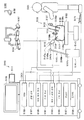
도 15를 참조하여, 내시경(5115)의 카메라 헤드(5119) 및 CCU(5153)의 기능에 대해 보다 상세하게 설명한다. 도 15는, 도 14에 나타내는 카메라 헤드(5119) 및 CCU(5153)의 기능 구성의 일례를 나타내는 블록도이다. Referring to FIG. 15, the functions of the
도 15를 참조하면, 카메라 헤드(5119)는, 그 기능으로서, 렌즈 유닛(5121)과, 촬상부(5123)와, 구동부(5125)와, 통신부(5127)와, 카메라 헤드 제어부(5129)를 포함한다. 또한, CCU(5153)는, 그 기능으로서, 통신부(5173)와, 화상 처리부(5175)와, 제어부(5177)를 포함한다. 카메라 헤드(5119)와 CCU(5153)는, 전송 케이블(5179)을 통해 쌍방향으로 통신 가능하게 접속되어 있다. Referring to FIG. 15, the
우선, 카메라 헤드(5119)의 기능 구성에 대해 설명한다. 렌즈 유닛(5121)은, 경통(5117)과의 접속부에 설치되는 광학계이다. 경통(5117)의 선단으로부터 취입된 관찰광은, 카메라 헤드(5119)까지 도광되어, 렌즈 유닛(5121)에 입사한다. 렌즈 유닛(5121)은, 줌 렌즈 및 포커스 렌즈를 포함한 복수의 렌즈가 조합되어 구성된다. 렌즈 유닛(5121)은, 촬상부(5123)의 촬상 소자의 수광면 상에 관찰광을 집광하도록, 그 광학 특성이 조정되어 있다. 또한, 줌 렌즈 및 포커스 렌즈는, 촬상 화상의 배율 및 초점의 조정을 위해, 그 광축 상의 위치가 이동 가능하게 구성된다. First, the functional configuration of the
촬상부(5123)는 촬상 소자에 의해 구성되고, 렌즈 유닛(5121)의 후단에 배치된다. 렌즈 유닛(5121)을 통과한 관찰광은, 촬상 소자의 수광면에 집광되고, 광전 변환에 의해, 관찰상에 대응한 화상 신호가 생성된다. 촬상부(5123)에 의해 생성된 화상 신호는, 통신부(5127)에 제공된다. The
촬상부(5123)를 구성하는 촬상 소자로서는, 예를 들면 CMOS(Complementary Metal Oxide Semiconductor) 타입의 이미지 센서이고, 베이어(Bayer) 배열을 가지는 컬러 촬영 가능한 것이 사용된다. 또한, 촬상 소자로서는, 예를 들면 4K 이상의 고해상도의 화상의 촬영에 대응 가능한 것이 사용되어도 된다. 수술부의 화상이 고해상도로 얻어짐으로써, 수술자(5181)는, 당해 수술부의 모습을 보다 상세하게 파악할 수 있어, 수술을 보다 원활하게 진행하는 것이 가능하게 된다. As an imaging device constituting the
또한, 촬상부(5123)를 구성하는 촬상 소자는, 3D 표시에 대응하는 우안용 및 좌안용의 화상 신호를 각각 취득하기 위한 한 쌍의 촬상 소자를 가지도록 구성된다. 3D 표시를 행함으로써, 수술자(5181)는 수술부에 있어서의 생체 조직의 깊이를 보다 정확하게 파악하는 것이 가능하게 된다. 또한, 촬상부(5123)가 다판식으로 구성되는 경우에는, 각 촬상 소자에 대응하여, 렌즈 유닛(5121)도 복수 계통 설치된다. Moreover, the imaging element which comprises the
또한, 촬상부(5123)는, 반드시 카메라 헤드(5119)에 설치되지 않아도 된다. 예를 들면, 촬상부(5123)는, 경통(5117)의 내부에, 대물렌즈의 바로 뒤에 설치되어도 된다. In addition, the
구동부(5125)는, 액추에이터에 의해 구성되고, 카메라 헤드 제어부(5129)로부터의 제어에 의해, 렌즈 유닛(5121)의 줌 렌즈 및 포커스 렌즈를 광축을 따라 소정의 거리만큼 이동시킨다. 이에 의해, 촬상부(5123)에 의한 촬상 화상의 배율 및 초점이 적절하게 조정될 수 있다. The
통신부(5127)는, CCU(5153)와의 사이에서 각종의 정보를 송수신하기 위한 통신 장치에 의해 구성된다. 통신부(5127)는, 촬상부(5123)로부터 얻은 화상 신호를 RAW 데이터로서 전송 케이블(5179)을 거쳐 CCU(5153)에 송신한다. 이 때, 수술부의 촬상 화상을 낮은 레이턴시로 표시하기 위해서, 당해 화상 신호는 광통신에 의해 송신되는 것이 바람직하다. 수술 중에는, 수술자(5181)가 촬상 화상에 의해 환부의 상태를 관찰하면서 수술을 행하기 때문에, 보다 안전하고 확실한 수술을 위해서는, 수술부의 동화상이 가능한 한 리얼타임으로 표시되는 것이 요구되기 때문이다. 광통신을 하는 경우에는, 통신부(5127)에는, 전기신호를 광신호로 변환하는 광전 변환 모듈이 설치된다. 화상 신호는 광전 변환 모듈에 의해 광신호로 변환된 후, 전송 케이블(5179)을 거쳐 CCU(5153)에 송신된다. The
또한, 통신부(5127)는, CCU(5153)로부터, 카메라 헤드(5119)의 구동을 제어하기 위한 제어 신호를 수신한다. 당해 제어 신호에는, 예를 들면, 촬상 화상의 프레임 레이트를 지정하는 취지의 정보, 촬상 시의 노출값을 지정하는 취지의 정보, 및/또는 촬상 화상의 배율 및 초점을 지정하는 취지의 정보 등, 촬상 조건에 관한 정보가 포함된다. 통신부(5127)는, 수신한 제어 신호를 카메라 헤드 제어부(5129)에 제공한다. 또한, CCU(5153)로부터의 제어 신호도, 광통신에 의해 전송되어도 된다. 이 경우, 통신부(5127)에는, 광신호를 전기신호로 변환하는 광전 변환 모듈이 설치되고, 제어 신호는 당해 광전 변환 모듈에 의해 전기신호로 변환된 후, 카메라 헤드 제어부(5129)에 제공된다. In addition, the
또한, 상기의 프레임 레이트나 노출값, 배율, 초점 등의 촬상 조건은, 취득된 화상 신호에 기초하여 CCU(5153)의 제어부(5177)에 의해 자동적으로 설정된다. 즉, 이른바 AE(Auto Exposure) 기능, AF(Auto Focus) 기능 및 AWB(Auto White Balance) 기능이 내시경(5115)에 탑재된다. In addition, imaging conditions such as the frame rate, exposure value, magnification, focus, and the like are automatically set by the
카메라 헤드 제어부(5129)는, 통신부(5127)를 거쳐 수신한 CCU(5153)로부터의 제어 신호에 기초하여, 카메라 헤드(5119)의 구동을 제어한다. 예를 들면, 카메라 헤드 제어부(5129)는, 촬상 화상의 프레임 레이트를 지정하는 취지의 정보 및/또는 촬상 시의 노광을 지정하는 취지의 정보에 기초하여, 촬상부(5123)의 촬상 소자의 구동을 제어한다. 또한, 예를 들면, 카메라 헤드 제어부(5129)는, 촬상 화상의 배율 및 초점을 지정하는 취지의 정보에 기초하여, 구동부(5125)를 거쳐 렌즈 유닛(5121)의 줌 렌즈 및 포커스 렌즈를 적절하게 이동시킨다. 카메라 헤드 제어부(5129)는, 경통(5117)이나 카메라 헤드(5119)를 식별하기 위한 정보를 기억하는 기능을 더 포함하여도 된다. The camera
또한, 렌즈 유닛(5121)이나 촬상부(5123) 등의 구성을, 기밀성 및 방수성이 높은 밀폐 구조 내에 배치함으로써, 카메라 헤드(5119)에 대해, 오토 클레이브 멸균 처리에 대한 내성을 갖게 할 수 있다. In addition, by arranging the structures of the
다음으로, CCU(5153)의 기능 구성에 대해 설명한다. 통신부(5173)는, 카메라 헤드(5119)와의 사이에 각종의 정보를 송수신하기 위한 통신 장치에 의해 구성된다. 통신부(5173)는, 카메라 헤드(5119)로부터, 전송 케이블(5179)을 거쳐서 송신되는 화상 신호를 수신한다. 이 때, 상기와 같이, 당해 화상 신호는 바람직하게는 광통신에 의해 송신될 수 있다. 이 경우, 광통신에 대응하여, 통신부(5173)에는, 광신호를 전기신호로 변환하는 광전 변환 모듈이 설치된다. 통신부(5173)는, 전기신호로 변환한 화상 신호를 화상 처리부(5175)에 제공한다. Next, the functional configuration of the CCU 5503 will be described. The
또한, 통신부(5173)는, 카메라 헤드(5119)에 대해서, 카메라 헤드(5119)의 구동을 제어하기 위한 제어 신호를 송신한다. 이 제어 신호도 광통신에 의해 송신되어도 된다. The
화상 처리부(5175)는, 카메라 헤드(5119)로부터 송신된 RAW 데이터로서의 화상 신호에 대해서 각종의 화상 처리를 실시한다. 당해 화상 처리로서는, 예를 들면 현상 처리, 고화질화 처리(대역 강조 처리, 초해상 처리, NR(Noise reduction) 처리 및/또는 손 떨림 보정 처리 등), 및/또는 확대 처리(전자 줌 처리) 등, 각종의 공지의 신호 처리가 포함된다. 또한, 화상 처리부(5175)는, AE, AF 및 AWB를 행하기 위한, 화상 신호에 대한 검파 처리를 행한다. The
화상 처리부(5175)는, CPU나 GPU 등의 프로세서에 의해 구성되고, 당해 프로세서가 소정의 프로그램에 따라 동작함으로써, 상술한 화상 처리나 검파 처리를 행할 수 있다. 또한, 화상 처리부(5175)가 복수의 GPU에 의해 구성되는 경우에는, 화상 처리부(5175)는, 화상 신호와 관련되는 정보를 적절하게 분할하여, 이들 복수의 GPU에 의해 병렬적으로 화상 처리를 행한다. The
제어부(5177)는, 내시경(5115)에 의한 수술부의 촬상, 및 그 촬상 화상의 표시에 관한 각종의 제어를 행한다. 예를 들면, 제어부(5177)는, 카메라 헤드(5119)의 구동을 제어하기 위한 제어 신호를 생성한다. 이 때, 촬상 조건이 유저에 의해 입력되고 있는 경우에는, 제어부(5177)는, 당해 유저에 의한 입력에 기초하여 제어 신호를 생성한다. 또는, 내시경(5115)에 AE기능, AF기능 및 AWB 기능이 탑재되어 있을 경우에는, 제어부(5177)는, 화상 처리부(5175)에 의한 검파 처리의 결과에 따라, 최적 노출값, 초점 거리 및 화이트 밸런스를 적절하게 산출하여, 제어 신호를 생성한다. The
또한, 제어부(5177)는, 화상 처리부(5175)에 의해 화상 처리가 실시된 화상 신호에 기초하여, 수술부의 화상을 표시 장치(5155)에 표시시킨다. 이 때, 제어부(5177)는, 각종의 화상 인식 기술을 사용하여 수술부 화상 내에 있어서의 각종의 물체를 인식한다. 예를 들면, 제어부(5177)는, 수술부 화상에 포함되는 물체의 엣지의 형상이나 색 등을 검출함으로써, 겸자 등의 수술도구, 특정의 생체 부위, 출혈, 에너지 처치구(5135) 사용 시의 미스트 등을 인식할 수 있다. 제어부(5177)는, 표시 장치(5155)에 수술부의 화상을 표시시킬 때에, 그 인식 결과를 이용하여, 각종의 수술 지원 정보를 당해 수술부의 화상에 중첩 표시시킨다. 수술 지원 정보가 중첩 표시되어, 수술자(5181)에게 제시됨으로써, 보다 안전하고 확실하게 수술을 진행시키는 것이 가능하게 된다. In addition, the
카메라 헤드(5119) 및 CCU(5153)를 접속하는 전송 케이블(5179)은, 전기신호의 통신을 지원하는 전기신호 케이블, 광통신을 지원하는 광섬유 또는 이들의 복합 케이블이다. The
여기서, 도시하는 예에서는, 전송 케이블(5179)을 사용하여 유선으로 통신을 행하고 있었지만, 카메라 헤드(5119)와 CCU(5153)와의 사이의 통신은 무선으로 행해져도 된다. 양자 사이의 통신이 무선으로 행해질 경우에는, 전송 케이블(5179)을 수술실 내에 부설할 필요가 없어지기 때문에, 수술실 내에 있어서의 의료 스탭의 이동이 당해 전송 케이블(5179)에 의해 방해되어지는 사태가 해소될 수 있다.Here, in the example shown, although the communication was performed by wire using the
이상, 본 개시와 관련되는 기술이 적용될 수 있는 수술실 시스템(5100)의 일례에 대해 설명했다. 또한, 여기서는, 일례로서 수술실 시스템(5100)이 적용되는 의료용 시스템이 내시경 수술 시스템(5113)인 경우에 대해 설명했지만, 수술실 시스템(5100)의 구성은 이들 예에 한정되지 않는다. 예를 들면, 수술실 시스템(5100)은, 내시경 하 수술 시스템(5113)에 대신하여, 검사용 연성 내시경 시스템이나 현미경 수술 시스템에 적용되어도 된다. In the above, an example of the
본 개시와 관련되는 기술은, 이상 설명한 구성 중, CCU(5153)의 제어부(5177)에 바람직하게 적용될 수 있다. 구체적으로는, 타겟 에리어로서 수수불 화상에 있어서의 초점 에리어를 설정하고, 이 타겟 에리어에 있어서 HDR 영상 신호의 밝기의 대표값을 산출하고, 이 밝기의 대표값에 기초하여 결정되는 부의 게인값을 HDR 영상 신호에 승산함으로써 영상 신호의 다이나믹 레인지를 압축하고, 그 다이나믹 레인지를 더욱 제2 다이나믹 레인지(SDR)로 제한하여 SDR 영상 신호를 생성하는 것이 가능하다. 본 개시에 따른 기술을 이와 같이 CCU(5153)의 제어부(5177)에 적용함으로써, 수술부 화상을 헤드 마운트 디스플레이를 이용하여 확인하거나, 또는 수술부 화상을 어두운 곳에서 SDR 모니터에서 확인할 때, 수술자의 시야에 특히 적합한 화상을 제공할 수 있다. 또한, 수술부 화상에 있어서, 초점 영역에 대해 적합한 휘도가 존재할 수 있다. 이러한 경우에, 예를 들어 도 16에 나타낸 바와 같은 초점 부위를 지정하기 위한 아이콘(5198)을 조작 화면(5193) 상에 표시시키서, 이 아이콘(5198)을 선택함으로써 타겟 에리어가 설정될 수 있다. 이때, 초점 부위에 적합한 영상 신호가 각각의 타겟 에리어에 대해 미리 결정된 부의 게인값을 사용하여 생성될 수 있다.The technique according to the present disclosure can be preferably applied to the
또한, 본 기술은 이하와 같은 구성도 취할 수 있다. In addition, this technology can also take the following structures.
(1) (One)
제1 다이나믹 레인지로 촬영된 제1 영상 신호를 취득하도록 구성된 제1 인터페이스와, A first interface configured to acquire a first video signal photographed with a first dynamic range,
상기 취득된 제1 영상 신호 중의 일부의 영역을 특정하기 위한 정보를 취득하도록 구성된 제2 인터페이스와, A second interface configured to acquire information for specifying a region of a part of the acquired first video signal;
상기 일부의 영역의 상기 제1 영상 신호의 밝기의 대표값을 산출하고, 상기 산출된 대표값에 따라 상기 제1 영상 신호의 다이나믹 레인지를 압축하고, 상기 제1 다이나믹 레인지보다 좁은 제2 다이나믹 레인지로 그 다이나믹 레인지를 제한한 제2 영상 신호를 생성하도록 구성된 연산 처리 회로A representative value of brightness of the first video signal in the partial region is calculated, and a dynamic range of the first video signal is compressed according to the calculated representative value, and the second dynamic range is narrower than the first dynamic range. An arithmetic processing circuit configured to generate a second video signal with a limited dynamic range
를 포함하는, 영상 신호 처리 장치.Image signal processing apparatus comprising a.
(2)(2)
상기 (1)에 있어서, In the above (1),
상기 연산 처리 회로는, 상기 산출된 대표값에 따른 게인값을 상기 제1 영상 신호에 승산함으로써 상기 제1 영상 신호의 다이나믹 레인지를 압축하도록 구성된, 영상 신호 처리 장치.And the arithmetic processing circuit is configured to compress the dynamic range of the first video signal by multiplying the gain value according to the calculated representative value by the first video signal.
(3)(3)
상기 (2)에 있어서, In the above (2),
상기 연산 처리 회로는, 상기 산출된 대표값이 클수록 절대치가 큰 부의 게인값을 상기 제1 영상 신호에 승산하도록 구성된, 영상 신호 처리 장치. And the arithmetic processing circuit is configured to multiply the first image signal by a negative gain value having a larger absolute value as the calculated representative value is larger.
(4)(4)
상기 (1) 내지 (3) 중 어느 하나에 있어서, In any one of said (1)-(3),
상기 연산 처리 회로는, 상기 제1 영상 신호 중의 상기 일부의 영역의 중앙 부분과 그 외의 부분 사이에서 밝기의 값의 가중을 다르게 함으로써 상기 밝기의 대표값을 산출하도록 구성된, 영상 신호 처리 장치. And the arithmetic processing circuit is configured to calculate the representative value of the brightness by varying the weighting of the brightness value between the central portion of the portion of the portion of the first image signal and the other portion.
(5)(5)
상기 (1) 내지 (4) 중 어느 하나에 있어서, In any one of said (1)-(4),
상기 연산 처리 회로는, 상기 제2 영상 신호에, 당해 제2 영상 신호의 고휘도부의 표시 레인지를 증대시키도록 고휘도부를 압축하는 형태의 감마 처리를 실시하도록 구성된, 영상 신호 처리 장치. And the arithmetic processing circuit is configured to perform gamma processing in the form of compressing a high luminance portion to increase the display range of the high luminance portion of the second image signal to the second image signal.
(6)(6)
상기 (1) 내지 (5) 중 어느 하나에 있어서, In any one of said (1)-(5),
상기 연산 처리 회로에 의해 생성된 제2 영상 신호를, 상기 제2 다이나믹 레인지로 영상을 표시 가능한 디스플레이를 포함한 기기에 출력하도록 구성된, 제3 인터페이스를 더 포함하는, 영상 신호 처리 장치.And a third interface, configured to output a second video signal generated by the arithmetic processing circuit to a device including a display capable of displaying an image in the second dynamic range.
(7)(7)
연산 처리 회로에 의해,By arithmetic processing circuit,
제1 인터페이스를 사용하여 제1 다이나믹 레인지로 촬영된 제1 영상 신호를 취득하는 단계와,Acquiring a first image signal photographed with a first dynamic range using the first interface;
제2 인터페이스를 사용하여 상기 취득된 제1 영상 신호 중의 일부의 영역을 특정하기 위한 정보를 취득하는 단계와, Acquiring information for specifying a region of a part of the acquired first video signal by using a second interface;
상기 일부의 영역의 상기 제1 영상 신호의 밝기의 대표값을 산출하고, 상기 산출된 대표값에 따라 상기 제1 영상 신호의 다이나믹 레인지를 압축하고, 상기 제1 다이나믹 레인지보다 좁은 제2 다이나믹 레인지로 그 다이나믹 레인지를 제한한 제2 영상 신호를 생성하는 단계,A representative value of brightness of the first video signal in the partial region is calculated, and a dynamic range of the first video signal is compressed according to the calculated representative value, and the second dynamic range is narrower than the first dynamic range. Generating a second video signal in which the dynamic range is limited;
를 포함하는, 영상 신호 처리 방법.A video signal processing method comprising a.
(8)(8)
상기 (7)에 있어서, In the above (7),
상기 연산 처리 회로는, 상기 산출된 대표값에 따른 게인값을 상기 제1 영상 신호에 승산함으로써 상기 제1 영상 신호의 다이나믹 레인지를 압축하는, 영상 신호 처리 방법.And the arithmetic processing circuit compresses the dynamic range of the first video signal by multiplying the gain value according to the calculated representative value by the first video signal.
(9)(9)
상기 (8)에 있어서, In the above (8),
상기 연산 처리 회로는, 상기 산출된 대표값이 클수록 절대치가 큰 부의 게인값을 상기 제1 영상 신호에 승산하는, 영상 신호 처리 방법. And the arithmetic processing circuit multiplies the first video signal by a negative gain value having a larger absolute value as the calculated representative value is larger.
(10)10
상기 (7) 내지 (9) 중 어느 하나에 있어서, In any one of said (7)-(9),
상기 연산 처리 회로는, 상기 제1 영상 신호 중의 상기 일부의 영역의 중앙 부분과 그 외의 부분 사이에서 밝기의 값의 가중을 다르게 함으로써 상기 밝기의 대표값을 산출하는, 영상 신호 처리 방법. And the arithmetic processing circuit calculates a representative value of the brightness by varying the weighting of the brightness value between a central portion and other portions of the partial region of the first video signal.
(11)(11)
상기 (7) 내지 (10) 중 어느 하나에 있어서, In any one of said (7)-(10),
상기 연산 처리 회로는, 상기 제2 영상 신호에, 당해 제2 영상 신호의 고휘도부의 표시 레인지를 증대시키도록 고휘도부를 압축하는 형태의 감마 처리를 실시하는, 영상 신호 처리 방법. And the arithmetic processing circuit performs a gamma processing of a form in which a high luminance unit is compressed to increase the display range of the high luminance unit of the second video signal.
(12)(12)
상기 (7) 내지 (11) 중 어느 하나에 있어서, In any one of said (7)-(11),
상기 연산 처리 회로에 의해 생성된 제2 영상 신호를, 상기 제2 다이나믹 레인지로 영상을 표시 가능한 디스플레이를 포함한 기기로 제3 인터페이스에 의해 출력하는 단계를 더 포함하는, 영상 신호 처리 방법.And outputting, by the third interface, the second video signal generated by the arithmetic processing circuit to a device including a display capable of displaying an image in the second dynamic range by a third interface.
(13) (13)
제1 다이나믹 레인지로 촬영된 제1 영상 신호를 취득하도록 구성된 제1 인터페이스와,A first interface configured to acquire a first video signal photographed with a first dynamic range,
상기 취득된 제1 영상 신호 중의 일부의 영역을 특정하기 위한 정보를 취득하도록 구성된 제2 인터페이스와, A second interface configured to acquire information for specifying a region of a part of the acquired first video signal;
상기 일부의 영역의 상기 제1 영상 신호의 밝기의 대표값을 산출하고, 상기 산출된 대표값에 따라 상기 제1 영상 신호의 다이나믹 레인지를 압축하고, 상기 제1 다이나믹 레인지보다 좁은 제2 다이나믹 레인지로 그 다이나믹 레인지를 제한한 제2 영상 신호를 생성하도록 구성된 연산 처리 회로A representative value of brightness of the first video signal in the partial region is calculated, and a dynamic range of the first video signal is compressed according to the calculated representative value, and the second dynamic range is narrower than the first dynamic range. An arithmetic processing circuit configured to generate a second video signal with a limited dynamic range
를 포함하는 영상 신호 처리 장치로서,An image signal processing apparatus comprising:
컴퓨터를 동작시키는 프로그램. A program that runs a computer.
(14)(14)
상기 (13)에 있어서, In the above (13),
상기 연산 처리 회로는, 상기 산출된 대표값에 따른 게인값을 상기 제1 영상 신호에 승산함으로써 상기 제1 영상 신호의 다이나믹 레인지를 압축하는, 프로그램.And said arithmetic processing circuit compresses the dynamic range of said first video signal by multiplying said first video signal by a gain value corresponding to said calculated representative value.
(15)(15)
상기 (14)에 있어서, In the above (14),
상기 연산 처리 회로는, 상기 산출된 대표값이 클수록 절대치가 큰 부의 게인값을 상기 제1 영상 신호에 승산하는, 프로그램.And the arithmetic processing circuit multiplies the first video signal by a negative gain value having a larger absolute value as the calculated representative value is larger.
(16)(16)
상기 (13) 내지 (15) 중 어느 하나에 있어서, In any one of said (13)-(15),
상기 연산 처리 회로는, 상기 제1 영상 신호 중의 상기 일부의 영역의 중앙 부분과 그 외의 부분 사이에서 밝기의 값의 가중을 다르게 함으로써 상기 밝기의 대표값을 산출하는, 프로그램. And said arithmetic processing circuit calculates a representative value of said brightness by varying the weighting of the value of brightness between the central portion and other portions of said portion of region of said first video signal.
(17)(17)
상기 (13) 내지 (16) 중 어느 하나에 있어서, In any one of said (13)-(16),
상기 연산 처리 회로는, 상기 제2 영상 신호에, 당해 제2 영상 신호의 고휘도부의 표시 레인지를 증대시키도록 고휘도부를 압축하는 형태의 감마 처리를 실시하는, 프로그램. And said arithmetic processing circuit performs gamma processing in the form of compressing a high brightness portion to increase the display range of the high brightness portion of said second video signal to said second video signal.
(18)(18)
상기 (13) 내지 (17) 중 어느 하나에 있어서, In any one of said (13)-(17),
제3 인터페이스가, 상기 연산 처리 회로에 의해 생성된 제2 영상 신호를, 상기 제2 다이나믹 레인지로 영상을 표시 가능한 디스플레이를 포함한 기기에 출력하는, 프로그램. And a third interface outputs a second video signal generated by the arithmetic processing circuit to a device including a display capable of displaying a video in the second dynamic range.
(19)(19)
전자기기로서, As an electronic device,
제1 다이나믹 레인지를 갖는 제1 영상 신호를 취득하고; 상기 제1 영상 신호 중 일부의 영역의 밝기의 대표값을 산출하고; 상기 산출된 대표값에 기초하여 상기 제1 영상 신호의 상기 제1 다이나믹 레인지를 변경하고; 상기 변경에 기초하여 상기 제1 다이나믹 레인지와는 다른 제2 다이나믹 레인지를 갖는 제2 영상 신호를 생성하도록 구성된 회로Acquire a first video signal having a first dynamic range; Calculating a representative value of brightness of a portion of the first image signal; Change the first dynamic range of the first video signal based on the calculated representative value; A circuit configured to generate a second image signal having a second dynamic range different from the first dynamic range based on the change
를 포함하는, 전자기기. Including, an electronic device.
(20)20
상기 (19)에 있어서, In the above (19),
상기 회로는, 상기 산출된 대표값에 기초하여 상기 제1 영상 신호의 다이나믹 레인지를 압축함으로써 상기 제1 영상 신호의 다이나믹 레인지를 변경하도록 구성된, 전자기기. The circuitry is configured to change the dynamic range of the first video signal by compressing the dynamic range of the first video signal based on the calculated representative value.
(21)(21)
상기 (19) 또는 (20)에 있어서, In the above (19) or (20),
상기 제2 영상 신호의 상기 제2 다이나믹 레인지는 상기 제1 영상 신호의 상기 제1 다이나믹 레인지보다 좁은, 전자기기. The second dynamic range of the second video signal is narrower than the first dynamic range of the first video signal.
(22)(22)
상기 (19) 내지 (21) 중 어느 하나에 있어서, In any one of said (19)-(21),
상기 회로는, 상기 제1 영상 신호 중 상기 일부의 영역을 특정하기 위한 정보를 취득하도록 구성된, 전자기기.And the circuit is configured to acquire information for specifying the region of the part of the first video signal.
(23)(23)
상기 (20)에 있어서, In the above (20),
상기 회로는, 상기 산출된 대표값에 대응하는 게인값을 상기 제1 영상 신호에 승산함으로써 상기 제1 영상 신호의 다이나믹 레인지를 압축하도록 구성된, 전자기기. And the circuit is configured to compress the dynamic range of the first video signal by multiplying the first video signal by a gain value corresponding to the calculated representative value.
(24)(24)
상기 (23)에 있어서,In the above (23),
상기 회로는, 부의 게인값을 상기 제1 영상 신호에 승산하도록 구성된, 전자기기. The circuit is configured to multiply a negative gain value by the first video signal.
(25)(25)
상기 (24)에 있어서, In the above (24),
상기 산출된 대표값이 제2 값일 때 상기 부의 게인값의 절대값은 제1 값이며, When the calculated representative value is the second value, the absolute value of the negative gain value is the first value,
상기 산출된 대표값이 상기 제2 값보다 큰 제4 값일 때 상기 부의 게인값의 절대값은 상기 제1 값보다 큰 제3 값인, When the calculated representative value is a fourth value greater than the second value, the absolute value of the negative gain value is a third value greater than the first value,
전자기기.Electronics.
(26)(26)
상기 (19) 내지 (25) 중 어느 하나에 있어서, In any one of said (19)-(25),
상기 회로는, 상기 일부의 영역의 중앙 부분에서의 밝기의 값에 제1 가중을, 그리고 상기 일부의 영역 외의 다른 부분에서의 밝기의 값에 상기 제1 가중과는 다른 제2 가중을 할당함으로써, 밝기의 대표값을 산출하도록 구성된, 전자기기. The circuit may be configured by assigning a first weight to a value of brightness in a central portion of the partial region and a second weight different from the first weight to a value of brightness in a portion other than the partial region, The electronic device, configured to calculate a representative value of brightness.
(27)(27)
상기 (19) 내지 (26) 중 어느 하나에 있어서, In any one of said (19)-(26),
상기 회로는, 상기 제2 영상 신호의 일부분을 압축하기 위한 감마 처리를 실시하여 상기 제2 영상 신호의 상기 일부분의 디스플레이 레인지를 증가시키도록 구성된, 전자기기.And the circuitry is configured to perform a gamma process to compress a portion of the second video signal to increase the display range of the portion of the second video signal.
(28)(28)
상기 (19) 내지 (27) 중 어느 하나에 있어서, In any one of said (19)-(27),
상기 회로는, 디스플레이를 포함하는 장치에 상기 제2 영상 신호를 출력하도록 구성된, 전자기기. The circuitry is configured to output the second video signal to a device including a display.
(29)(29)
상기 (19) 내지 (28) 중 어느 하나에 있어서, In any one of said (19)-(28),
상기 회로는, The circuit,
상기 제1 영상 신호를 취득하도록 구성된 제1 통신 인터페이스; 및A first communication interface configured to acquire the first video signal; And
상기 일부의 영역을 특정하기 위한 정보를 취득하도록 구성된 제2 통신 인터페이스A second communication interface configured to obtain information for specifying the partial area
를 포함하는, 전자기기. Including, an electronic device.
(30)(30)
상기 (29)에 있어서,In the above (29),
상기 회로는, 디스플레이를 포함하는 장치에 상기 제2 영상 신호를 출력하도록 구성된 제3 통신 인터페이스를 포함하는, 전자기기. The circuitry comprises a third communication interface configured to output the second video signal to a device including a display.
(31)(31)
전자기기에 의해 수행되는 영상 신호 처리 방법으로서,An image signal processing method performed by an electronic device,
제1 다이나믹 레인지를 갖는 제1 영상 신호를 취득하는 단계;Acquiring a first image signal having a first dynamic range;
상기 제1 영상 신호의 일부의 영역의 밝기의 대표값을 산출하는 단계;Calculating a representative value of brightness of a portion of the first image signal;
상기 산출된 대표값에 기초하여 상기 제1 영상 신호의 제1 다이나믹 레인지를 변경하는 단계; 및Changing a first dynamic range of the first video signal based on the calculated representative value; And
상기 변경에 기초하여 상기 제1 다이나믹 레인지와는 다른 제2 다이나믹 레인지를 갖는 제2 영상 신호를 생성하는 단계,Generating a second image signal having a second dynamic range different from the first dynamic range based on the change;
를 포함하는,영상 신호 처리 방법. Including, Image signal processing method.
(32)(32)
비일시적 컴퓨터 판독가능 매체로서, A non-transitory computer readable medium,
전자기기에 의해 실행되었을 때, 상기 전자기기로 하여금, When executed by an electronic device, the electronic device causes
제1 다이나믹 레인지를 갖는 제1 영상 신호를 취득하는 단계;Acquiring a first image signal having a first dynamic range;
상기 제1 영상 신호의 일부의 영역의 밝기의 대표값을 산출하는 단계;Calculating a representative value of brightness of a portion of the first image signal;
상기 산출된 대표값에 기초하여 상기 제1 영상 신호의 상기 제1 다아나믹 레인지를 변경하는 단계; 및Changing the first dynamic range of the first image signal based on the calculated representative value; And
상기 변경에 기초하여 상기 제1 다이나믹 레인지와는 다른 제2 다이나믹 레인지를 갖는 제2 영상 신호를 생성하는 단계,Generating a second image signal having a second dynamic range different from the first dynamic range based on the change;
를 수행하도록 하는 컴퓨터 프로그램 명령어를 포함하는, A computer program instruction for performing a
비일시적 컴퓨터 판독가능 매체. Non-transitory Computer-readable Media.
(33)(33)
전자기기로서, As an electronic device,
제1 다이나믹 레인지를 갖는 영상 신호를 취득하고; 상기 영상 신호의 전체 미만인 상기 영상 신호의 제1 부분의 밝기를 나타내는 제1 값을 산출하고; 상기 산출된 값에 기초하여 상기 영상 신호의 상기 제1 부분의 제1 다이나믹 레인지를 변경하도록 구성된 회로Acquire a video signal having a first dynamic range; Calculating a first value representing a brightness of a first portion of the video signal that is less than all of the video signal; Circuitry configured to change a first dynamic range of the first portion of the video signal based on the calculated value
를 포함하는, 전자기기. Including, an electronic device.
(34)(34)
상기 (33)에 있어서, In the above (33),
상기 회로는, The circuit,
상기 영상 신호의 전체 미만인 상기 영상 신호의 제2 부분의 밝기를 나타내는 제2 값을 산출하고; 상기 산출된 값에 기초하여 상기 영상 신호의 상기 제2 부분의 제1 다이나믹 레인지를 변경하도록 구성된, 전자기기. Calculating a second value representing the brightness of a second portion of the video signal that is less than all of the video signal; And change a first dynamic range of the second portion of the video signal based on the calculated value.
(35)(35)
상기 (33) 또는 (34)에 있어서, In the above (33) or (34),
상기 회로는, 상기 제1 다이나믹 레인지를, 당해 제1 다이나믹 레인지보다 좁은 제2 다이나믹 레인지로 축소함으로써 상기 영상 신호의 상기 제1 부분의 제1 다이나믹 레인지를 변경하도록 구성된, 전자기기. And the circuit is configured to change the first dynamic range of the first portion of the video signal by reducing the first dynamic range to a second dynamic range that is narrower than the first dynamic range.
(36)(36)
상기 (33) 내지 (35) 중 어느 하나에 있어서, In any one of said (33)-(35),
상기 회로는, 상기 산출된 제1 값에 기초하여 상기 영상 신호의 상기 제1 부분의 제1 다이나믹 레인지를 압축하도록 구성된, 전자기기. The circuitry is configured to compress a first dynamic range of the first portion of the video signal based on the calculated first value.
(37)(37)
상기 (36)에 있어서,In the above (36),
상기 회로는, 상기 산출된 제1 값에 대응하는 게인값을 상기 제1 영상 신호에 승산함으로써 상기 영상 신호의 상기 제1 부분의 제1 다이나믹 레인지를 압축하도록 구성된, 전자기기. And the circuit is configured to compress the first dynamic range of the first portion of the video signal by multiplying the first video signal by a gain value corresponding to the calculated first value.
(38)(38)
상기 (33) 내지 (37) 중 어느 하나에 있어서, In any one of (33)-(37),
상기 회로는, 상기 산출된 제1 값에 대응하는 부의 게인값을 상기 제1 영상 신호에 승산함으로써 상기 영상 신호의 상기 제1 부분의 제1 다이나믹 레인지를 축소하도록 구성된, 전자기기. And the circuit is configured to reduce the first dynamic range of the first portion of the video signal by multiplying the first video signal by a negative gain value corresponding to the calculated first value.
(39)(39)
상기 (20)에 있어서,In the above (20),
상기 산출된 제1 값이 제3 값일 경우에, 상기 부의 게인값의 절대값은 제2 값이고, When the calculated first value is a third value, the absolute value of the negative gain value is a second value,
상기 산출된 제1 값이 상기 제3 값보다 큰 제5 값일 경우에, 상기 부의 게인의 절대값은 상기 제2 값보다 큰 제4 값인, 전자기기. And when the calculated first value is a fifth value greater than the third value, the absolute value of the negative gain is a fourth value greater than the second value.
(40)40
상기 (33) 내지 (39) 중 어느 하나에 있어서,In any one of (33) to (39),
상기 회로는, 상기 제1 부분의 중앙 영역에서의 밝기의 값에 제1 가중을, 그리고 상기 제1 부분 외의 다른 영역에서의 밝기의 값에 상기 제1 가중과는 다른 제2 가중을 할당함으로써 상기 제1 값을 산출하도록 구성된, 전자기기. The circuit may be configured by assigning a first weight to a value of brightness in a central region of the first portion and a second weight different from the first weight to a value of brightness in a region other than the first portion. The electronic device configured to calculate a first value.
(41)(41)
상기 (33) 내지 (40) 중 어느 하나에 있어서, In any one of (33)-(40),
상기 회로는, 상기 영상 신호의 상기 제1 부분에 대해 감마 처리를 실시하여 상기 영상 신호의 상기 제1 부분의 디스플레이 레인지를 증가시키도록 구성된, 전자기기. And the circuitry is configured to perform a gamma processing on the first portion of the video signal to increase the display range of the first portion of the video signal.
(42)(42)
상기 (33) 내지 (41) 중 어느 하나에 있어서, In any one of said (33)-(41),
상기 회로는, 디스플레이를 포함하는 장치에 상기 영상 신호의 상기 제1 부분을 출력하도록 구성된, 전자기기. The circuitry is configured to output the first portion of the video signal to a device including a display.
(43)(43)
상기 (33) 내지 (42) 중 어느 하나에 있어서, In any one of said (33)-(42),
상기 회로는,The circuit,
상기 영상 신호의 상기 제1 부분의 밝기 히스토그램을 산출하고;Calculate a brightness histogram of the first portion of the video signal;
상기 영상 신호의 상기 제1 부분의 복수의 영역 사이의 평균 밝기에 있어서의 차가 임계값을 초과하는지를 판정하고, It is determined whether a difference in average brightness between a plurality of areas of the first portion of the video signal exceeds a threshold value,
상기 판정에 기초하여, 상기 영상 신호의 상기 제1 부분의 제1 다이나믹 레인지를 변경하도록 구성된, 전자기기.And change the first dynamic range of the first portion of the video signal based on the determination.
(44)(44)
전자기기에 의해 수행되는 영상 처리 방법으로서, An image processing method performed by an electronic device,
제1 다이나믹 레인지를 갖는 영상 신호를 취득하는 단계;Acquiring an image signal having a first dynamic range;
상기 전자기기의 회로에 의해, 상기 영상 신호의 전체 미만인 상기 영상 신호의 제1 부분의 밝기를 나타내는 제1 값을 산출하는 단계; 및Calculating, by the circuitry of the electronic device, a first value representing the brightness of the first portion of the video signal that is less than the entirety of the video signal; And
상기 회로에 의해, 상기 산출된 값에 기초하여 상기 영상 신호의 상기 제1 부분의 제1 다이나믹 레인지를 변경하는 단계,Changing, by the circuit, a first dynamic range of the first portion of the video signal based on the calculated value,
를 포함하는, 영상 처리 방법.Image processing method comprising a.
(45)(45)
비일시적 컴퓨터 판독가능 매체로서, A non-transitory computer readable medium,
전자기기에 의해 실행되었을 때, 상기 전자기기로 하여금, When executed by an electronic device, the electronic device causes
제1 다이나믹 레인지를 갖는 영상 신호를 취득하는 단계;Acquiring an image signal having a first dynamic range;
상기 영상 신호의 전체 미만인 상기 영상 신호의 제1 부분의 밝기를 나타내는 제1 값을 산출하는 단계; 및Calculating a first value representing a brightness of a first portion of the video signal that is less than all of the video signal; And
상기 산출된 값에 기초하여 상기 영상 신호의 상기 제1 부분의 제1 다이나믹 레인지를 변경하는 단계,Changing a first dynamic range of the first portion of the video signal based on the calculated value,
를 수행하도록 하는 컴퓨터 프로그램 명령어를 포함하는, A computer program instruction for performing a
비일시적 컴퓨터 판독가능 매체. Non-transitory Computer-readable Media.
당해 기술 분야에서 통상의 지식을 갖춘 자라면, 첨부된 청구범위 또는 그 균등 범위 내에 있는 한, 설계 요건 및 다른 요인에 따라 다양한 변형, 조합, 서브 조합 및 변경에 상도할 수 있음을 알 수 있다. Those skilled in the art will appreciate that various modifications, combinations, subcombinations, and modifications may be made, depending upon design requirements and other factors, as long as they are within the scope of the appended claims or their equivalents.
1: 영상 신호 처리 시스템
10: 촬상 유닛
11: 카메라
20: VR 신호 처리 유닛
30: 인코드/배신 유닛
40: 정보처리장치
41: CPU
42: 메모리
42: 통신 인터페이스
43: 통신 인터페이스
44: 통신 인터페이스
45: 통신 인터페이스
50: 헤드 마운트 디스플레이(HMD)
60: HMD용 콘트롤러
70: 네트워크 1: video signal processing system
10: imaging unit
11: camera
20: VR signal processing unit
30: Encode / Delivery Unit
40: information processing device
41: CPU
42: memory
42: communication interface
43: communication interface
44: communication interface
45: communication interface
50: head mounted display (HMD)
60: controller for HMD
70: network
Claims (27)
제1 다이나믹 레인지를 갖는 제1 영상 신호를 취득하고; 상기 제1 영상 신호 중 일부의 영역의 밝기의 대표값을 산출하고; 상기 산출된 대표값에 기초하여 상기 제1 영상 신호의 상기 제1 다이나믹 레인지를 변경하고; 상기 변경에 기초하여 상기 제1 다이나믹 레인지와는 다른 제2 다이나믹 레인지를 갖는 제2 영상 신호를 생성하도록 구성된 회로
를 포함하는, 전자기기. As an electronic device,
Acquire a first video signal having a first dynamic range; Calculating a representative value of brightness of a portion of the first image signal; Change the first dynamic range of the first video signal based on the calculated representative value; A circuit configured to generate a second image signal having a second dynamic range different from the first dynamic range based on the change
Including, an electronic device.
상기 회로는, 상기 산출된 대표값에 기초하여 상기 제1 영상 신호의 다이나믹 레인지를 압축함으로써 상기 제1 영상 신호의 다이나믹 레인지를 변경하도록 구성된, 전자기기. The method of claim 1,
The circuitry is configured to change the dynamic range of the first video signal by compressing the dynamic range of the first video signal based on the calculated representative value.
상기 제2 영상 신호의 상기 제2 다이나믹 레인지는 상기 제1 영상 신호의 상기 제1 다이나믹 레인지보다 좁은, 전자기기. The method of claim 1,
The second dynamic range of the second video signal is narrower than the first dynamic range of the first video signal.
상기 회로는, 상기 제1 영상 신호 중 상기 일부의 영역을 특정하기 위한 정보를 취득하도록 구성된, 전자기기.The method of claim 1,
And the circuit is configured to acquire information for specifying the region of the part of the first video signal.
상기 회로는, 상기 산출된 대표값에 대응하는 게인값을 상기 제1 영상 신호에 승산함으로써 상기 제1 영상 신호의 다이나믹 레인지를 압축하도록 구성된, 전자기기. The method of claim 2,
And the circuit is configured to compress the dynamic range of the first video signal by multiplying the first video signal by a gain value corresponding to the calculated representative value.
상기 회로는, 부의 게인값을 상기 제1 영상 신호에 승산하도록 구성된, 전자기기. The method of claim 5,
The circuit is configured to multiply a negative gain value by the first video signal.
상기 산출된 대표값이 제2 값일 때 상기 부의 게인값의 절대값은 제1 값이며,
상기 산출된 대표값이 상기 제2 값보다 큰 제4 값일 때 상기 부의 게인값의 절대값은 상기 제1 값보다 큰 제3 값인,
전자기기.The method of claim 6,
When the calculated representative value is the second value, the absolute value of the negative gain value is the first value,
When the calculated representative value is a fourth value greater than the second value, the absolute value of the negative gain value is a third value greater than the first value,
Electronics.
상기 회로는, 상기 일부의 영역의 중앙 부분에서의 밝기의 값에 제1 가중을, 그리고 상기 일부의 영역 외의 다른 부분에서의 밝기의 값에 상기 제1 가중과는 다른 제2 가중을 할당함으로써, 밝기의 대표값을 산출하도록 구성된, 전자기기. The method of claim 1,
The circuit may be configured by assigning a first weight to a value of brightness in a central portion of the partial region and a second weight different from the first weight to a value of brightness in a portion other than the partial region, The electronic device, configured to calculate a representative value of brightness.
상기 회로는, 상기 제2 영상 신호의 일부분을 압축하기 위한 감마 처리를 실시하여 상기 제2 영상 신호의 상기 일부분의 디스플레이 레인지를 증가시키도록 구성된, 전자기기.The method of claim 1,
And the circuitry is configured to perform a gamma process to compress a portion of the second video signal to increase the display range of the portion of the second video signal.
상기 회로는, 디스플레이를 포함하는 장치에 상기 제2 영상 신호를 출력하도록 구성된, 전자기기. The method of claim 1,
The circuitry is configured to output the second video signal to a device including a display.
상기 회로는,
상기 제1 영상 신호를 취득하도록 구성된 제1 통신 인터페이스; 및
상기 일부의 영역을 특정하기 위한 정보를 취득하도록 구성된 제2 통신 인터페이스
를 포함하는, 전자기기. The method of claim 1,
The circuit,
A first communication interface configured to acquire the first video signal; And
A second communication interface configured to obtain information for specifying the partial area
Including, an electronic device.
상기 회로는, 디스플레이를 포함하는 장치에 상기 제2 영상 신호를 출력하도록 구성된 제3 통신 인터페이스를 포함하는, 전자기기. The method of claim 11,
The circuitry comprises a third communication interface configured to output the second video signal to a device including a display.
제1 다이나믹 레인지를 갖는 제1 영상 신호를 취득하는 단계;
상기 제1 영상 신호의 일부의 영역의 밝기의 대표값을 산출하는 단계;
상기 산출된 대표값에 기초하여 상기 제1 영상 신호의 제1 다이나믹 레인지를 변경하는 단계; 및
상기 변경에 기초하여 상기 제1 다이나믹 레인지와는 다른 제2 다이나믹 레인지를 갖는 제2 영상 신호를 생성하는 단계,
를 포함하는,영상 신호 처리 방법. An image signal processing method performed by an electronic device,
Acquiring a first image signal having a first dynamic range;
Calculating a representative value of brightness of a portion of the first image signal;
Changing a first dynamic range of the first video signal based on the calculated representative value; And
Generating a second image signal having a second dynamic range different from the first dynamic range based on the change;
Including, Image signal processing method.
전자기기에 의해 실행되었을 때, 상기 전자기기로 하여금,
제1 다이나믹 레인지를 갖는 제1 영상 신호를 취득하는 단계;
상기 제1 영상 신호의 일부의 영역의 밝기의 대표값을 산출하는 단계;
상기 산출된 대표값에 기초하여 상기 제1 영상 신호의 상기 제1 다아나믹 레인지를 변경하는 단계; 및
상기 변경에 기초하여 상기 제1 다이나믹 레인지와는 다른 제2 다이나믹 레인지를 갖는 제2 영상 신호를 생성하는 단계,
를 수행하도록 하는 컴퓨터 프로그램 명령어를 포함하는,
비일시적 컴퓨터 판독가능 매체. A non-transitory computer readable medium,
When executed by an electronic device, the electronic device causes
Acquiring a first image signal having a first dynamic range;
Calculating a representative value of brightness of a portion of the first image signal;
Changing the first dynamic range of the first image signal based on the calculated representative value; And
Generating a second image signal having a second dynamic range different from the first dynamic range based on the change;
A computer program instruction for performing a
Non-transitory Computer-readable Media.
제1 다이나믹 레인지를 갖는 영상 신호를 취득하고; 상기 영상 신호의 전체 미만인 상기 영상 신호의 제1 부분의 밝기를 나타내는 제1 값을 산출하고; 상기 산출된 값에 기초하여 상기 영상 신호의 상기 제1 부분의 제1 다이나믹 레인지를 변경하도록 구성된 회로
를 포함하는, 전자기기. As an electronic device,
Acquire a video signal having a first dynamic range; Calculating a first value representing a brightness of a first portion of the video signal that is less than all of the video signal; Circuitry configured to change a first dynamic range of the first portion of the video signal based on the calculated value
Including, an electronic device.
상기 회로는,
상기 영상 신호의 전체 미만인 상기 영상 신호의 제2 부분의 밝기를 나타내는 제2 값을 산출하고; 상기 산출된 값에 기초하여 상기 영상 신호의 상기 제2 부분의 제1 다이나믹 레인지를 변경하도록 구성된, 전자기기. The method of claim 15,
The circuit,
Calculating a second value representing the brightness of a second portion of the video signal that is less than all of the video signal; And change a first dynamic range of the second portion of the video signal based on the calculated value.
상기 회로는, 상기 제1 다이나믹 레인지를, 당해 제1 다이나믹 레인지보다 좁은 제2 다이나믹 레인지로 축소함으로써 상기 영상 신호의 상기 제1 부분의 제1 다이나믹 레인지를 변경하도록 구성된, 전자기기. The method of claim 15,
And the circuit is configured to change the first dynamic range of the first portion of the video signal by reducing the first dynamic range to a second dynamic range that is narrower than the first dynamic range.
상기 회로는, 상기 산출된 제1 값에 기초하여 상기 영상 신호의 상기 제1 부분의 제1 다이나믹 레인지를 압축하도록 구성된, 전자기기. The method of claim 15,
The circuitry is configured to compress a first dynamic range of the first portion of the video signal based on the calculated first value.
상기 회로는, 상기 산출된 제1 값에 대응하는 게인값을 상기 제1 영상 신호에 승산함으로써 상기 영상 신호의 상기 제1 부분의 제1 다이나믹 레인지를 압축하도록 구성된, 전자기기. The method of claim 18,
And the circuit is configured to compress the first dynamic range of the first portion of the video signal by multiplying the first video signal by a gain value corresponding to the calculated first value.
상기 회로는, 상기 산출된 제1 값에 대응하는 부의 게인값을 상기 제1 영상 신호에 승산함으로써 상기 영상 신호의 상기 제1 부분의 제1 다이나믹 레인지를 축소하도록 구성된, 전자기기. The method of claim 15,
And the circuit is configured to reduce the first dynamic range of the first portion of the video signal by multiplying the first video signal by a negative gain value corresponding to the calculated first value.
상기 산출된 제1 값이 제3 값일 경우에, 상기 부의 게인값의 절대값은 제2 값이고,
상기 산출된 제1 값이 상기 제3 값보다 큰 제5 값일 경우에, 상기 부의 게인의 절대값은 상기 제2 값보다 큰 제4 값인, 전자기기. The method of claim 20,
When the calculated first value is a third value, the absolute value of the negative gain value is a second value,
And when the calculated first value is a fifth value greater than the third value, the absolute value of the negative gain is a fourth value greater than the second value.
상기 회로는, 상기 제1 부분의 중앙 영역에서의 밝기의 값에 제1 가중을, 그리고 상기 제1 부분 외의 다른 영역에서의 밝기의 값에 상기 제1 가중과는 다른 제2 가중을 할당함으로써 상기 제1 값을 산출하도록 구성된, 전자기기. The method of claim 15,
The circuit may be configured by assigning a first weight to a value of brightness in a central region of the first portion and a second weight different from the first weight to a value of brightness in a region other than the first portion. The electronic device configured to calculate a first value.
상기 회로는, 상기 영상 신호의 상기 제1 부분에 대해 감마 처리를 실시하여 상기 영상 신호의 상기 제1 부분의 디스플레이 레인지를 증가시키도록 구성된, 전자기기. The method of claim 15,
And the circuitry is configured to perform a gamma processing on the first portion of the video signal to increase the display range of the first portion of the video signal.
상기 회로는, 디스플레이를 포함하는 장치에 상기 영상 신호의 상기 제1 부분을 출력하도록 구성된, 전자기기. The method of claim 15,
The circuitry is configured to output the first portion of the video signal to a device including a display.
상기 회로는,
상기 영상 신호의 상기 제1 부분의 밝기 히스토그램을 산출하고;
상기 영상 신호의 상기 제1 부분의 복수의 영역 사이의 평균 밝기에 있어서의 차가 임계값을 초과하는지를 판정하고,
상기 판정에 기초하여, 상기 영상 신호의 상기 제1 부분의 제1 다이나믹 레인지를 변경하도록 구성된, 전자기기.The method of claim 15,
The circuit,
Calculate a brightness histogram of the first portion of the video signal;
It is determined whether a difference in average brightness between a plurality of areas of the first portion of the video signal exceeds a threshold value,
And change the first dynamic range of the first portion of the video signal based on the determination.
제1 다이나믹 레인지를 갖는 영상 신호를 취득하는 단계;
상기 전자기기의 회로에 의해, 상기 영상 신호의 전체 미만인 상기 영상 신호의 제1 부분의 밝기를 나타내는 제1 값을 산출하는 단계; 및
상기 회로에 의해, 상기 산출된 값에 기초하여 상기 영상 신호의 상기 제1 부분의 제1 다이나믹 레인지를 변경하는 단계,
를 포함하는, 영상 처리 방법.An image processing method performed by an electronic device,
Acquiring an image signal having a first dynamic range;
Calculating, by the circuitry of the electronic device, a first value representing the brightness of the first portion of the video signal that is less than the entirety of the video signal; And
Changing, by the circuit, a first dynamic range of the first portion of the video signal based on the calculated value,
Image processing method comprising a.
전자기기에 의해 실행되었을 때, 상기 전자기기로 하여금,
제1 다이나믹 레인지를 갖는 영상 신호를 취득하는 단계;
상기 영상 신호의 전체 미만인 상기 영상 신호의 제1 부분의 밝기를 나타내는 제1 값을 산출하는 단계; 및
상기 산출된 값에 기초하여 상기 영상 신호의 상기 제1 부분의 제1 다이나믹 레인지를 변경하는 단계,
를 수행하도록 하는 컴퓨터 프로그램 명령어를 포함하는,
비일시적 컴퓨터 판독가능 매체. A non-transitory computer readable medium,
When executed by an electronic device, the electronic device causes
Acquiring an image signal having a first dynamic range;
Calculating a first value representing a brightness of a first portion of the video signal that is less than all of the video signal; And
Changing a first dynamic range of the first portion of the video signal based on the calculated value,
A computer program instruction for performing a
Non-transitory Computer-readable Media.
Applications Claiming Priority (3)
| Application Number | Priority Date | Filing Date | Title |
|---|---|---|---|
| JPJP-P-2017-007470 | 2017-01-19 | ||
| JP2017007470A JP6852411B2 (en) | 2017-01-19 | 2017-01-19 | Video signal processing device, video signal processing method and program |
| PCT/JP2017/047179 WO2018135291A1 (en) | 2017-01-19 | 2017-12-28 | Video signal processing apparatus, video signal processing method, and program for dynamic range compression |
Publications (1)
| Publication Number | Publication Date |
|---|---|
| KR20190109406A true KR20190109406A (en) | 2019-09-25 |
Family
ID=61017980
Family Applications (1)
| Application Number | Title | Priority Date | Filing Date |
|---|---|---|---|
| KR1020197020501A KR20190109406A (en) | 2017-01-19 | 2017-12-28 | Video signal processing apparatus, video signal processing method, and program for dynamic range compression |
Country Status (6)
| Country | Link |
|---|---|
| US (1) | US11403741B2 (en) |
| EP (1) | EP3571662B1 (en) |
| JP (1) | JP6852411B2 (en) |
| KR (1) | KR20190109406A (en) |
| CN (1) | CN110168605B (en) |
| WO (1) | WO2018135291A1 (en) |
Families Citing this family (7)
| Publication number | Priority date | Publication date | Assignee | Title |
|---|---|---|---|---|
| CN107800979B (en) * | 2017-10-23 | 2019-06-28 | 深圳看到科技有限公司 | High dynamic range video image pickup method and filming apparatus |
| WO2019193807A1 (en) * | 2018-04-06 | 2019-10-10 | ソニー株式会社 | Image processing device, image processing method, and recording medium |
| JP7344654B2 (en) * | 2019-03-07 | 2023-09-14 | キヤノン株式会社 | Imaging device and playback device and their control method and program |
| CN113392675B (en) * | 2020-03-12 | 2023-04-07 | 平湖莱顿光学仪器制造有限公司 | Method and equipment for presenting microscopic video information |
| EP4341929A1 (en) * | 2021-05-19 | 2024-03-27 | Dolby Laboratories Licensing Corporation | Display management with position-varying adaptivity to ambient light and/or non-display-originating surface light |
| US11734806B2 (en) | 2021-11-24 | 2023-08-22 | Roku, Inc. | Dynamic tone mapping |
| CN115547230B (en) * | 2022-11-23 | 2023-03-10 | 南京芯视元电子有限公司 | Video data display processing method and device, micro display screen and storage medium |
Citations (2)
| Publication number | Priority date | Publication date | Assignee | Title |
|---|---|---|---|---|
| WO2011004222A1 (en) | 2009-07-10 | 2011-01-13 | Kamil Bal | Pedicular screw system |
| JP2016195379A (en) | 2016-01-05 | 2016-11-17 | ソニー株式会社 | Video system, video processing method, program, camera system and video converter |
Family Cites Families (45)
| Publication number | Priority date | Publication date | Assignee | Title |
|---|---|---|---|---|
| EP0258740B1 (en) * | 1986-09-02 | 1995-07-19 | Fuji Photo Film Co., Ltd. | Method of and apparatus for processing an image with gradation correction of video signal |
| JP2003319933A (en) * | 2002-05-01 | 2003-11-11 | Fuji Photo Film Co Ltd | Picture display system |
| JP3801126B2 (en) * | 2002-09-25 | 2006-07-26 | ソニー株式会社 | Imaging apparatus, image output method of imaging apparatus, and computer program |
| CN101686306A (en) * | 2003-09-11 | 2010-03-31 | 松下电器产业株式会社 | Visual processing device, visual processing method, visual processing program, integrated circuit, display device, imaging device, and mobile information terminal |
| JP4736792B2 (en) * | 2004-12-27 | 2011-07-27 | コニカミノルタホールディングス株式会社 | Imaging apparatus and image processing method used therefor |
| WO2007043460A1 (en) * | 2005-10-12 | 2007-04-19 | Matsushita Electric Industrial Co., Ltd. | Visual processing apparatus, display apparatus, visual processing method, program and integrated circuit |
| EP2290983B1 (en) * | 2006-01-23 | 2015-09-02 | Max-Planck-Gesellschaft zur Förderung der Wissenschaften e.V. | High dynamic range codecs |
| US8687087B2 (en) * | 2006-08-29 | 2014-04-01 | Csr Technology Inc. | Digital camera with selectively increased dynamic range by control of parameters during image acquisition |
| JP2008305122A (en) * | 2007-06-07 | 2008-12-18 | Sony Corp | Image-processing apparatus, image processing method and program |
| KR20100089828A (en) * | 2007-10-26 | 2010-08-12 | 다이요 유덴 가부시키가이샤 | Video display device and method, and signal processing circuit and liquid crystal backlight drive device used in the same |
| US8270759B2 (en) * | 2008-06-16 | 2012-09-18 | International Business Machines Corporation | Transformation of a video image from a high dynamic range image to a low dynamic range image |
| EP2406959B1 (en) * | 2009-03-13 | 2015-01-14 | Dolby Laboratories Licensing Corporation | Layered compression of high dynamic range, visual dynamic range, and wide color gamut video |
| US9300938B2 (en) * | 2010-07-22 | 2016-03-29 | Dolby Laboratories Licensing Corporation | Systems, apparatus and methods for mapping between video ranges of image data and display |
| JP5409577B2 (en) * | 2010-10-05 | 2014-02-05 | 株式会社ソニー・コンピュータエンタテインメント | Panorama image generation apparatus and panorama image generation method |
| GB2500835B (en) * | 2010-12-10 | 2014-02-12 | Ibm | High-dynamic range video tone mapping |
| US8391598B2 (en) * | 2011-01-05 | 2013-03-05 | Aptina Imaging Corporation | Methods for performing local tone mapping |
| TWI513327B (en) * | 2011-04-15 | 2015-12-11 | Dolby Lab Licensing Corp | Encoding, decoding, and representing high dynamic range images |
| EP2774361B1 (en) * | 2011-11-01 | 2015-09-16 | Dolby Laboratories Licensing Corporation | Adaptive false contouring prevention in layered coding of images with extended dynamic range |
| JP2013118468A (en) * | 2011-12-02 | 2013-06-13 | Sony Corp | Image processing device and image processing method |
| JP5828039B2 (en) * | 2012-06-11 | 2015-12-02 | 株式会社ソニー・コンピュータエンタテインメント | Image generating apparatus and image generating method |
| CA2820241C (en) * | 2012-06-13 | 2020-01-14 | Robert G. Hilkes | An apparatus and method for enhancing human visual performance in a head worn video system |
| JP2014016670A (en) * | 2012-07-05 | 2014-01-30 | Nikon Corp | Image processing device and image processing program |
| FR3003378A1 (en) * | 2013-03-12 | 2014-09-19 | St Microelectronics Grenoble 2 | TONE MAPPING METHOD |
| JP2014216975A (en) * | 2013-04-30 | 2014-11-17 | ソニー株式会社 | Exposure control device, imaging apparatus and exposure control method |
| JP6131843B2 (en) * | 2013-11-28 | 2017-05-24 | 株式会社Jvcケンウッド | Depth estimation apparatus, depth estimation method, depth estimation program, and image processing apparatus |
| US9594488B2 (en) * | 2013-12-12 | 2017-03-14 | Google Inc. | Interactive display of high dynamic range images |
| EP2938084A4 (en) * | 2013-12-27 | 2016-10-26 | Sony Corp | Image processing device and image processing method |
| US9445111B2 (en) * | 2014-01-08 | 2016-09-13 | Sony Corporation | Image processing apparatus and image processing method |
| EP2922288A1 (en) * | 2014-03-18 | 2015-09-23 | Thomson Licensing | Method for processing a video sequence, corresponding device, computer program and non-transitory computer-readable medium |
| ES2694858T3 (en) * | 2014-05-28 | 2018-12-27 | Koninklijke Philips N.V. | Methods and apparatus for encoding HDR images, and methods and apparatus for the use of such encoded images |
| MX368411B (en) * | 2014-08-08 | 2019-10-02 | Koninklijke Philips Nv | Methods and apparatuses for encoding hdr images. |
| EP3205082B1 (en) * | 2014-10-10 | 2018-04-04 | Koninklijke Philips N.V. | Saturation processing specification for dynamic range mappings |
| US10136074B2 (en) * | 2015-06-02 | 2018-11-20 | Samsung Electronics Co., Ltd. | Distribution-point-based adaptive tone mapping |
| US10007412B2 (en) * | 2015-06-24 | 2018-06-26 | Samsung Electronics Co., Ltd. | Tone mastering system with creative intent metadata |
| US9741305B2 (en) * | 2015-08-04 | 2017-08-22 | Apple Inc. | Devices and methods of adaptive dimming using local tone mapping |
| US10043251B2 (en) * | 2015-10-09 | 2018-08-07 | Stmicroelectronics Asia Pacific Pte Ltd | Enhanced tone mapper for high dynamic range images and video |
| US10200701B2 (en) * | 2015-10-14 | 2019-02-05 | Qualcomm Incorporated | HDR and WCG coding architecture with SDR backwards compatibility in a single bitstream for video coding |
| US9621767B1 (en) * | 2015-11-24 | 2017-04-11 | Intel Corporation | Spatially adaptive tone mapping for display of high dynamic range (HDR) images |
| US10593028B2 (en) * | 2015-12-03 | 2020-03-17 | Samsung Electronics Co., Ltd. | Method and apparatus for view-dependent tone mapping of virtual reality images |
| WO2017129793A1 (en) * | 2016-01-28 | 2017-08-03 | Koninklijke Philips N.V. | Encoding and decoding hdr videos |
| CN108781246B (en) * | 2016-03-14 | 2021-05-28 | 皇家飞利浦有限公司 | Saturation handling assignment for dynamic range mapping |
| EP3220349A1 (en) * | 2016-03-16 | 2017-09-20 | Thomson Licensing | Methods, apparatus, and systems for extended high dynamic range ("hdr") hdr to hdr tone mapping |
| GB2549696A (en) * | 2016-04-13 | 2017-11-01 | Sony Corp | Image processing method and apparatus, integrated circuitry and recording medium |
| JP6822122B2 (en) * | 2016-12-19 | 2021-01-27 | ソニー株式会社 | Image processing equipment, image processing methods and programs |
| JP7196833B2 (en) * | 2017-03-15 | 2022-12-27 | ソニーグループ株式会社 | IMAGING DEVICE, VIDEO SIGNAL PROCESSING DEVICE, AND VIDEO SIGNAL PROCESSING METHOD |
-
2017
- 2017-01-19 JP JP2017007470A patent/JP6852411B2/en active Active
- 2017-12-28 WO PCT/JP2017/047179 patent/WO2018135291A1/en unknown
- 2017-12-28 CN CN201780083242.3A patent/CN110168605B/en active Active
- 2017-12-28 US US16/477,647 patent/US11403741B2/en active Active
- 2017-12-28 EP EP17832827.4A patent/EP3571662B1/en active Active
- 2017-12-28 KR KR1020197020501A patent/KR20190109406A/en unknown
Patent Citations (2)
| Publication number | Priority date | Publication date | Assignee | Title |
|---|---|---|---|---|
| WO2011004222A1 (en) | 2009-07-10 | 2011-01-13 | Kamil Bal | Pedicular screw system |
| JP2016195379A (en) | 2016-01-05 | 2016-11-17 | ソニー株式会社 | Video system, video processing method, program, camera system and video converter |
Also Published As
| Publication number | Publication date |
|---|---|
| US20200126197A1 (en) | 2020-04-23 |
| WO2018135291A1 (en) | 2018-07-26 |
| JP6852411B2 (en) | 2021-03-31 |
| US11403741B2 (en) | 2022-08-02 |
| CN110168605A (en) | 2019-08-23 |
| EP3571662A1 (en) | 2019-11-27 |
| CN110168605B (en) | 2023-05-30 |
| EP3571662B1 (en) | 2024-03-06 |
| JP2018117276A (en) | 2018-07-26 |
Similar Documents
| Publication | Publication Date | Title |
|---|---|---|
| CN110168605B (en) | Video signal processing apparatus, video signal processing method, and computer readable medium for dynamic range compression | |
| EP3534620B1 (en) | Signal processing device and method, and program | |
| CN110945399B (en) | Signal processing apparatus, imaging apparatus, signal processing method, and memory | |
| WO2019187502A1 (en) | Image processing apparatus, image processing method, and program | |
| US11729519B2 (en) | Video signal processing apparatus, video signal processing method, and image-capturing apparatus | |
| WO2018230510A1 (en) | Image processing device, image processing method, and image capture system | |
| US11729493B2 (en) | Image capture apparatus and image capture method | |
| US11022859B2 (en) | Light emission control apparatus, light emission control method, light emission apparatus, and imaging apparatus | |
| US11778325B2 (en) | Image processing apparatus, image processing method, and image processing program | |
| US11910105B2 (en) | Video processing using a blended tone curve characteristic | |
| US11902692B2 (en) | Video processing apparatus and video processing method | |
| WO2021230001A1 (en) | Information processing apparatus and information processing method | |
| WO2020066972A1 (en) | Receiving device, receiving method, and image processing system | |
| WO2020084999A1 (en) | Image processing device, image processing method, and program |