KR20190104184A - Detection device - Google Patents
Detection device Download PDFInfo
- Publication number
- KR20190104184A KR20190104184A KR1020197022529A KR20197022529A KR20190104184A KR 20190104184 A KR20190104184 A KR 20190104184A KR 1020197022529 A KR1020197022529 A KR 1020197022529A KR 20197022529 A KR20197022529 A KR 20197022529A KR 20190104184 A KR20190104184 A KR 20190104184A
- Authority
- KR
- South Korea
- Prior art keywords
- similarity
- data
- phase
- calculated
- calculating
- Prior art date
Links
Images


Classifications
-
- G—PHYSICS
- G01—MEASURING; TESTING
- G01N—INVESTIGATING OR ANALYSING MATERIALS BY DETERMINING THEIR CHEMICAL OR PHYSICAL PROPERTIES
- G01N21/00—Investigating or analysing materials by the use of optical means, i.e. using sub-millimetre waves, infrared, visible or ultraviolet light
- G01N21/84—Systems specially adapted for particular applications
- G01N21/88—Investigating the presence of flaws or contamination
- G01N21/95—Investigating the presence of flaws or contamination characterised by the material or shape of the object to be examined
- G01N21/952—Inspecting the exterior surface of cylindrical bodies or wires
-
- D—TEXTILES; PAPER
- D01—NATURAL OR MAN-MADE THREADS OR FIBRES; SPINNING
- D01H—SPINNING OR TWISTING
- D01H13/00—Other common constructional features, details or accessories
- D01H13/32—Counting, measuring, recording or registering devices
-
- G—PHYSICS
- G01—MEASURING; TESTING
- G01B—MEASURING LENGTH, THICKNESS OR SIMILAR LINEAR DIMENSIONS; MEASURING ANGLES; MEASURING AREAS; MEASURING IRREGULARITIES OF SURFACES OR CONTOURS
- G01B11/00—Measuring arrangements characterised by the use of optical techniques
- G01B11/02—Measuring arrangements characterised by the use of optical techniques for measuring length, width or thickness
-
- G—PHYSICS
- G01—MEASURING; TESTING
- G01B—MEASURING LENGTH, THICKNESS OR SIMILAR LINEAR DIMENSIONS; MEASURING ANGLES; MEASURING AREAS; MEASURING IRREGULARITIES OF SURFACES OR CONTOURS
- G01B11/00—Measuring arrangements characterised by the use of optical techniques
- G01B11/24—Measuring arrangements characterised by the use of optical techniques for measuring contours or curvatures
-
- G—PHYSICS
- G01—MEASURING; TESTING
- G01B—MEASURING LENGTH, THICKNESS OR SIMILAR LINEAR DIMENSIONS; MEASURING ANGLES; MEASURING AREAS; MEASURING IRREGULARITIES OF SURFACES OR CONTOURS
- G01B21/00—Measuring arrangements or details thereof, where the measuring technique is not covered by the other groups of this subclass, unspecified or not relevant
- G01B21/02—Measuring arrangements or details thereof, where the measuring technique is not covered by the other groups of this subclass, unspecified or not relevant for measuring length, width, or thickness
-
- G—PHYSICS
- G01—MEASURING; TESTING
- G01N—INVESTIGATING OR ANALYSING MATERIALS BY DETERMINING THEIR CHEMICAL OR PHYSICAL PROPERTIES
- G01N21/00—Investigating or analysing materials by the use of optical means, i.e. using sub-millimetre waves, infrared, visible or ultraviolet light
- G01N21/84—Systems specially adapted for particular applications
- G01N21/88—Investigating the presence of flaws or contamination
- G01N21/89—Investigating the presence of flaws or contamination in moving material, e.g. running paper or textiles
- G01N21/892—Investigating the presence of flaws or contamination in moving material, e.g. running paper or textiles characterised by the flaw, defect or object feature examined
-
- D—TEXTILES; PAPER
- D07—ROPES; CABLES OTHER THAN ELECTRIC
- D07B—ROPES OR CABLES IN GENERAL
- D07B1/00—Constructional features of ropes or cables
- D07B1/14—Ropes or cables with incorporated auxiliary elements, e.g. for marking, extending throughout the length of the rope or cable
- D07B1/145—Ropes or cables with incorporated auxiliary elements, e.g. for marking, extending throughout the length of the rope or cable comprising elements for indicating or detecting the rope or cable status
-
- D—TEXTILES; PAPER
- D07—ROPES; CABLES OTHER THAN ELECTRIC
- D07B—ROPES OR CABLES IN GENERAL
- D07B2301/00—Controls
- D07B2301/55—Sensors
- D07B2301/5531—Sensors using electric means or elements
- D07B2301/5572—Sensors using electric means or elements optical
Landscapes
- Physics & Mathematics (AREA)
- General Physics & Mathematics (AREA)
- Engineering & Computer Science (AREA)
- Textile Engineering (AREA)
- General Health & Medical Sciences (AREA)
- Chemical & Material Sciences (AREA)
- Analytical Chemistry (AREA)
- Biochemistry (AREA)
- Life Sciences & Earth Sciences (AREA)
- Health & Medical Sciences (AREA)
- Immunology (AREA)
- Pathology (AREA)
- Mechanical Engineering (AREA)
- Length Measuring Devices By Optical Means (AREA)
- Length Measuring Devices With Unspecified Measuring Means (AREA)
- Investigating Materials By The Use Of Optical Means Adapted For Particular Applications (AREA)
- Spinning Or Twisting Of Yarns (AREA)
Abstract
위상 산출부(12)는, 유사도 산출부(11)에 의해 산출된 제 1 유사도 및 제 2 유사도를 요소로 하는 제 1 유사도 벡터의 편각을 제 1 위상으로서 산출한다. 위상 산출부(12)는, 유사도 산출부(11)에 의해 산출된 제 3 유사도 및 제 4 유사도를 요소로 하는 제 2 유사도 벡터의 편각을 제 2 위상으로서 산출한다. 주기 산출부(13)는, 위상 산출부(12)에 의해 산출된 제 1 위상 및 제 2 위상에 근거하여, 긴 물체에 형성된 모양의 주기를 산출한다. 이상 검출부(14)는, 주기 산출부(13)에 의해 산출된 주기에 근거하여, 긴 물체의 이상을 검출한다.The phase calculator 12 calculates the declination angle of the first similarity vector having the first similarity and the second similarity calculated by the similarity calculator 11 as the first phase. The phase calculator 12 calculates the polarization angle of the second similarity vector having the third similarity and the fourth similarity calculated by the similarity calculator 11 as the second phase. The period calculating unit 13 calculates a period of a shape formed in the long object based on the first phase and the second phase calculated by the phase calculating unit 12. The abnormality detection unit 14 detects an abnormality of the long object based on the period calculated by the period calculating unit 13.
Description
본 발명은, 긴 물체를 검출 대상으로 하는 검출 장치에 관한 것이다.The present invention relates to a detection device that targets a long object to be detected.
특허문헌 1에, 로프를 검사하는 장치가 기재되어 있다. 특허문헌 1에 기재된 장치는, 광원과 수광 소자를 구비한다. 광원과 수광 소자의 사이에 로프가 배치된다. 특허문헌 1에 기재된 장치에서는, 수광 소자가 받은 광량에 근거하여 로프의 직경이 산출된다. 산출한 직경의 피크 값의 간격을 스트랜드(strand)의 간격에 일치시키는 것에 의해, 로프의 위치를 산출한다.In
특허문헌 1에 기재된 장치에서는, 로프의 이동 속도가 변동하고 있으면, 로프의 이동 속도가 변동하고 있는 것인지 로프의 스트랜드 피치가 변동하고 있는 것인지를 구별할 수 없다. 즉, 특허문헌 1에 기재된 장치에서 채용되어 있는 검출 방법에서는, 로프의 이동 속도가 변동하고 있으면, 로프에 발생한 이상, 예컨대 피치 이상을 검출할 수 없었다.In the apparatus described in
본 발명은, 상술한 바와 같은 과제를 해결하기 위해 이루어졌다. 본 발명의 목적은, 긴 물체의 이동 속도가 변동하고 있는 경우에도, 긴 물체의 이상을 검출할 수 있는 검출 장치를 제공하는 것이다.The present invention has been made to solve the above problems. An object of the present invention is to provide a detection device capable of detecting an abnormality of a long object even when the moving speed of the long object is fluctuating.
본 발명과 관련되는 검출 장치는, 표면에 주기적인 모양을 갖는 긴 물체의 제 1 표면 데이터 및 제 2 표면 데이터를 취득하는 데이터 취득 수단과, 제 1 레퍼런스 데이터 및 제 2 레퍼런스 데이터를 기억하는 기억 수단과, 데이터 취득 수단에 의해 취득된 제 1 표면 데이터와 제 1 레퍼런스 데이터의 제 1 유사도, 데이터 취득 수단에 의해 취득된 제 1 표면 데이터와 제 2 레퍼런스 데이터의 제 2 유사도, 데이터 취득 수단에 의해 취득된 제 2 표면 데이터와 제 1 레퍼런스 데이터의 제 3 유사도, 및 데이터 취득 수단에 의해 취득된 제 2 표면 데이터와 제 2 레퍼런스 데이터의 제 4 유사도를 산출하는 유사도 산출 수단과, 유사도 산출 수단에 의해 산출된 제 1 유사도 및 제 2 유사도를 요소로 하는 제 1 유사도 벡터의 편각을 제 1 위상으로서 산출하고, 유사도 산출 수단에 의해 산출된 제 3 유사도 및 제 4 유사도를 요소로 하는 제 2 유사도 벡터의 편각을 제 2 위상으로서 산출하는 위상 산출 수단과, 위상 산출 수단에 의해 산출된 제 1 위상 및 제 2 위상에 근거하여, 긴 물체에 형성된 모양의 주기를 산출하는 주기 산출 수단과, 주기 산출 수단에 의해 산출된 주기에 근거하여, 긴 물체의 이상을 검출하는 제 1 이상 검출 수단을 구비한다.The detection apparatus according to the present invention includes data acquisition means for acquiring first surface data and second surface data of an elongated object having a periodic shape on the surface, and storage means for storing the first reference data and the second reference data. And first similarity of the first surface data and the first reference data acquired by the data acquiring means, second similarity of the first surface data and the second reference data acquired by the data acquiring means, and acquiring by the data acquiring means. A similarity calculating means for calculating a third similarity degree of the second surface data and the first reference data, and a fourth similarity degree of the second surface data and the second reference data acquired by the data acquiring means, and the similarity calculating means. Calculating the declination angle of the first similarity vector having the first similarity degree and the second similarity factor as the first phase, and calculating the similarity degree. Phase calculating means for calculating a polarization angle of the second similarity vector having the third similarity and the fourth similarity calculated by the means as the second phase, and based on the first phase and the second phase calculated by the phase calculating means. And a first abnormality detecting means for detecting an abnormality of the long object based on the period calculated by the periodic calculating means.
본 발명과 관련되는 검출 장치는, 표면에 주기적인 모양을 갖는 긴 물체의 복수의 표면 데이터를 취득하는 데이터 취득 수단과, 제 1 레퍼런스 데이터 및 제 2 레퍼런스 데이터를 기억하는 기억 수단과, 데이터 취득 수단에 의해 취득된 표면 데이터 중에서 제 1 표면 데이터 및 제 2 표면 데이터를 선택하는 선택 수단과, 선택 수단에 의해 선택된 제 1 표면 데이터와 제 1 레퍼런스 데이터의 제 1 유사도, 선택 수단에 의해 선택된 제 1 표면 데이터와 제 2 레퍼런스 데이터의 제 2 유사도, 선택 수단에 의해 선택된 제 2 표면 데이터와 제 1 레퍼런스 데이터의 제 3 유사도, 및 선택 수단에 의해 선택된 제 2 표면 데이터와 제 2 레퍼런스 데이터의 제 4 유사도를 산출하는 유사도 산출 수단과, 유사도 산출 수단에 의해 산출된 제 1 유사도 및 제 2 유사도를 요소로 하는 제 1 유사도 벡터의 편각을 제 1 위상으로서 산출하고, 유사도 산출 수단에 의해 산출된 제 3 유사도 및 제 4 유사도를 요소로 하는 제 2 유사도 벡터의 편각을 제 2 위상으로서 산출하는 위상 산출 수단과, 위상 산출 수단에 의해 산출된 제 1 위상 및 제 2 위상에 근거하여, 긴 물체에 형성된 모양의 주기를 산출하는 주기 산출 수단과, 주기 산출 수단에 의해 산출된 주기에 근거하여, 긴 물체의 이상을 검출하는 제 1 이상 검출 수단을 구비한다.The detection apparatus according to the present invention includes data acquisition means for acquiring a plurality of surface data of a long object having a periodic shape on a surface, storage means for storing first reference data and second reference data, and data acquisition means. Selecting means for selecting the first surface data and the second surface data from the surface data acquired by the first means; a first similarity between the first surface data and the first reference data selected by the selecting means, and a first surface selected by the selecting means. A second similarity of the data and the second reference data, a third similarity of the second surface data and the first reference data selected by the selecting means, and a fourth similarity of the second surface data and the second reference data selected by the selecting means Similarity calculation means for calculating and first similarity and second similarity calculated by the similarity calculating means as elements Phase calculating means for calculating the declination of the first similarity vector as the first phase, and calculating the declination of the second similarity vector including the third similarity and the fourth similarity calculated by the similarity calculating means as the second phase; The abnormality of the long object based on the period calculated by the period calculating means and the period calculating means for calculating the period of the shape formed in the long object based on the first phase and the second phase calculated by the phase calculating means. The first abnormality detection means which detects this is provided.
본 발명과 관련되는 검출 장치는, 표면에 주기적인 모양을 갖는 제 1 긴 물체의 제 1 표면 데이터 및 제 1 긴 물체의 표면에 형성된 모양과 동일한 모양을 표면에 갖는 제 2 긴 물체의 제 2 표면 데이터를 취득하는 데이터 취득 수단과, 제 1 레퍼런스 데이터 및 제 2 레퍼런스 데이터를 기억하는 기억 수단과, 데이터 취득 수단에 의해 취득된 제 1 표면 데이터와 제 1 레퍼런스 데이터의 제 1 유사도, 데이터 취득 수단에 의해 취득된 제 1 표면 데이터와 제 2 레퍼런스 데이터의 제 2 유사도, 데이터 취득 수단에 의해 취득된 제 2 표면 데이터와 제 1 레퍼런스 데이터의 제 3 유사도, 및 데이터 취득 수단에 의해 취득된 제 2 표면 데이터와 제 2 레퍼런스 데이터의 제 4 유사도를 산출하는 유사도 산출 수단과, 유사도 산출 수단에 의해 산출된 제 1 유사도 및 제 2 유사도를 요소로 하는 제 1 유사도 벡터의 편각을 제 1 위상으로서 산출하고, 유사도 산출 수단에 의해 산출된 제 3 유사도 및 제 4 유사도를 요소로 하는 제 2 유사도 벡터의 편각을 제 2 위상으로서 산출하는 위상 산출 수단과, 위상 산출 수단에 의해 산출된 제 1 위상 및 제 2 위상에 근거하여, 제 1 긴 물체 또는 제 2 긴 물체에 이상이 발생한 것을 검출하는 제 1 이상 검출 수단을 구비한다.The detection apparatus according to the present invention includes a first surface data of a first long object having a periodic shape on the surface and a second surface of a second long object having a shape identical to the shape formed on the surface of the first long object. Data acquisition means for acquiring data, storage means for storing the first reference data and the second reference data, first similarity of the first surface data and the first reference data acquired by the data acquisition means, and data acquisition means. Second similarity degree of the first surface data and the second reference data acquired by the third third degree of similarity of the second surface data and the first reference data acquired by the data acquiring means, and second surface data acquired by the data acquiring means. And similarity calculating means for calculating a fourth similarity degree of the second reference data, and first and second similarities calculated by the similarity calculating means. Calculating the declination angle of the first similarity vector including the degrees as the first phase, and calculating the declination angle of the second similarity vector including the third similarity and the fourth similarity calculated by the similarity calculating means as the second phase. And a first abnormality detecting means for detecting that an abnormality has occurred in the first long object or the second long object based on the first phase and the second phase calculated by the phase calculating means.
본 발명과 관련되는 검출 장치는, 예컨대 유사도 산출 수단, 위상 산출 수단, 주기 산출 수단 및 제 1 이상 검출 수단을 구비한다. 위상 산출 수단은, 제 1 유사도 벡터의 편각을 제 1 위상으로서 산출하고, 제 2 유사도 벡터의 편각을 제 2 위상으로서 산출한다. 주기 산출 수단은, 위상 산출 수단에 의해 산출된 제 1 위상 및 제 2 위상에 근거하여, 긴 물체에 형성된 모양의 주기를 산출한다. 제 1 이상 검출 수단은, 주기 산출 수단에 의해 산출된 주기에 근거하여 긴 물체의 이상을 검출한다. 본 발명과 관련되는 검출 장치이면, 긴 물체의 이동 속도가 변동하고 있는 경우에도, 긴 물체의 이상을 검출할 수 있다.The detection apparatus which concerns on this invention is equipped with a similarity calculation means, a phase calculation means, a period calculation means, and a 1st abnormality detection means, for example. The phase calculating means calculates the declination of the first similarity vector as the first phase, and calculates the declination of the second similarity vector as the second phase. The period calculating means calculates the period of the shape formed in the long object based on the first phase and the second phase calculated by the phase calculating means. The first abnormality detecting means detects an abnormality of the long object based on the period calculated by the period calculating means. According to the detection device according to the present invention, even when the moving speed of the long object is fluctuating, abnormality of the long object can be detected.
도 1은 본 발명의 실시의 형태 1에 있어서의 검출 장치의 예를 나타내는 도면이다.
도 2는 도 1에 나타내는 화살표 A의 방향으로부터 긴 물체를 본 도면이다.
도 3은 수광 소자에 의해 취득된 수광 화상의 처리 방법을 나타내는 도면이다.
도 4는 제어 장치의 예를 나타내는 도면이다.
도 5는 데이터 처리부의 기능을 설명하기 위한 도면이다.
도 6은 레퍼런스 데이터의 예를 나타내는 도면이다.
도 7은 위상 산출부의 기능을 설명하기 위한 도면이다.
도 8은 본 발명의 실시의 형태 1에 있어서의 검출 장치의 동작의 예를 나타내는 플로차트이다.
도 9는 센서 헤드의 다른 예를 설명하기 위한 도면이다.
도 10은 수광 소자에 의해 취득된 수광 화상의 처리 방법을 나타내는 도면이다.
도 11은 센서 헤드의 다른 예를 설명하기 위한 도면이다.
도 12는 센서 헤드의 다른 예를 설명하기 위한 도면이다.
도 13은 카메라에 의해 촬영된 화상 데이터의 처리 방법을 나타내는 도면이다.
도 14는 본 발명의 실시의 형태 2에 있어서의 제어 장치의 예를 나타내는 도면이다.
도 15는 본 발명의 실시의 형태 2에 있어서의 검출 장치의 동작의 예를 나타내는 플로차트이다.
도 16은 선택부의 기능을 설명하기 위한 도면이다.
도 17은 본 발명의 실시의 형태 3에 있어서의 검출 장치의 예를 나타내는 도면이다.
도 18은 도 17에 나타내는 화살표 A의 방향으로부터 긴 물체를 본 도면이다.
도 19는 수광 소자에 의해 취득된 수광 화상의 처리 방법을 나타내는 도면이다.
도 20은 제어 장치의 예를 나타내는 도면이다.
도 21은 위상 산출부의 기능을 설명하기 위한 도면이다.
도 22는 제어 장치의 하드웨어 구성의 예를 나타내는 도면이다.BRIEF DESCRIPTION OF THE DRAWINGS It is a figure which shows the example of the detection apparatus in
FIG. 2 is a view of an elongated object from the direction of arrow A shown in FIG. 1.
3 is a diagram illustrating a processing method of a light received image acquired by the light receiving element.
4 is a diagram illustrating an example of a control device.
5 is a view for explaining the function of the data processing unit.
6 is a diagram illustrating an example of reference data.
7 is a diagram for explaining the function of the phase calculator.
8 is a flowchart showing an example of the operation of the detection apparatus according to the first embodiment of the present invention.
9 is a diagram for explaining another example of the sensor head.
10 is a diagram illustrating a processing method of a light received image acquired by the light receiving element.
11 is a diagram for explaining another example of the sensor head.
12 is a diagram for explaining another example of the sensor head.
13 is a diagram illustrating a method of processing image data photographed by a camera.
It is a figure which shows an example of the control apparatus in
15 is a flowchart showing an example of the operation of the detection apparatus according to the second embodiment of the present invention.
16 is a diagram for explaining the function of the selection unit.
It is a figure which shows the example of the detection apparatus in
FIG. 18 is a view of an elongated object from the direction of arrow A shown in FIG. 17.
19 is a diagram illustrating a method of processing a light received image acquired by the light receiving element.
20 is a diagram illustrating an example of a control device.
21 is a diagram for explaining the function of the phase calculator.
It is a figure which shows the example of the hardware structure of a control apparatus.
첨부한 도면을 참조하여, 본 발명을 설명한다. 중복되는 설명은, 적당히 간략화 혹은 생략한다. 각 도면에 있어서, 동일한 부호는 동일한 부분 또는 상당하는 부분을 나타낸다.The present invention will be described with reference to the accompanying drawings. Overlapping descriptions are appropriately simplified or omitted. In each figure, the same code | symbol shows the same part or the corresponding part.
실시의 형태 1.
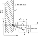
도 1은 본 발명의 실시의 형태 1에 있어서의 검출 장치의 예를 나타내는 도면이다. 검출 장치는, 긴 물체의 이상을 검출하기 위한 장치이다. 긴 물체에는, 예컨대 로프(1)가 포함된다. 도 2는 도 1에 나타내는 화살표 A의 방향으로부터 긴 물체를 본 도면이다.BRIEF DESCRIPTION OF THE DRAWINGS It is a figure which shows the example of the detection apparatus in
설명을 용이하게 하기 위해, 도 1 및 도 2에 나타내는 바와 같이, x축, y축 및 z축을 설정한다. y축은, 긴 물체의 긴 방향을 향하는 축이다. x축은, y축 및 z축에 직교한다. z축은, y축 및 x축에 직교한다. x축, y축 및 z축은, 3차원 공간 상에서의 좌표를 나타내기 위해 설정된 축이다. 도 2는, +z 방향으로부터 긴 물체를 본 도면에 상당한다.For ease of explanation, as shown in Figs. 1 and 2, the x-axis, the y-axis and the z-axis are set. The y axis is an axis that faces the long direction of the long object. The x axis is orthogonal to the y axis and the z axis. The z axis is orthogonal to the y axis and the x axis. The x-axis, y-axis, and z-axis are axes set to represent coordinates in three-dimensional space. 2 corresponds to a view of an object long from the + z direction.
긴 물체는, 긴 방향으로 이동한다. 예컨대, 로프(1)는 +y 방향 혹은 -y 방향으로 이동한다. 이와 같이 이동하는 로프(1)의 예로서, 엘리베이터에서 사용되는 와이어 로프를 들 수 있다. 로프(1)는, +y 방향 및 -y 방향의 양쪽으로 이동하더라도 좋다. 또, 검출 장치가 검출 대상으로 하는 긴 물체는, 로프(1)로 한정되지 않는다.The long object moves in the long direction. For example, the
로프(1)는, 복수의 스트랜드를 구비한다. 로프(1)는, 복수의 스트랜드가 꼬아 합쳐지는 것에 의해 형성된다. 이 때문에, 로프(1)는, 표면에 주기적인 모양을 갖는다. 본 검출 장치가 이상을 검출하는 대상은, 표면에 주기적인 모양을 갖는 긴 물체이다. "모양"에는, 예컨대 형상, 도형, 색 및 색의 농담이 포함된다. 도 1 및 도 2는 8개의 스트랜드가 꼬아 합쳐지는 것에 의해 로프(1)가 형성되는 예를 나타낸다. 로프(1)의 표면에는, 복수의 스트랜드가 꼬아 합쳐지는 것에 의해 형성되는 요철이 규칙적으로 늘어서 있다. 이상적인 로프(1)의 단면 형상은, 꼬임 피치를 스트랜드의 수로 나눈 거리마다 동일하게 된다. 상기 단면이란, 로프(1)의 긴 방향과 직교하는 방향의 단면이다. 꼬임 피치를 스트랜드의 수로 나눈 거리는, 스트랜드 피치, 즉 모양의 주기이다.The
본 실시의 형태에 나타내는 예에서는, 검출 장치는, 긴 물체에 형성된 모양의 주기를 산출하고, 이상의 유무를 판정한다. 검출 장치는, 예컨대 센서 헤드(2)와 제어 장치(3)를 구비한다.In the example shown in this embodiment, a detection apparatus calculates the period of the pattern formed in the elongate object, and determines the presence or absence of abnormality. The detection device includes, for example, a
센서 헤드(2)는, 긴 물체의 표면 데이터를 취득하는 수단의 일례이다. "표면 데이터"는, 긴 물체의 표면의 모양에 관한 데이터이다. 본 실시의 형태에 나타내는 예에서는, 센서 헤드(2)는, 긴 물체의 2개소의 표면 데이터를 동시에 취득한다. 예컨대, 센서 헤드(2)는, 로프(1) 중 제 1 위치를 통과하는 부분의 표면에 형성된 요철을 나타내는 데이터를 제 1 표면 데이터로서 취득한다. 동시에, 센서 헤드(2)는, 로프(1) 중 제 2 위치를 통과하는 부분의 표면에 형성된 요철을 나타내는 데이터를 제 2 표면 데이터로서 취득한다. 제 2 위치는, 제 1 위치와는 상이한 위치이다. 예컨대, 제 2 위치는, 제 1 위치로부터 y축 방향으로 일정 거리만큼 떨어진 위치이다. 도 1은 센서 헤드(2)가 광학식의 프로파일 측정기인 예를 나타낸다. 센서 헤드(2)는, 예컨대 광원(4), 광원(5), 수광 소자(6) 및 수광 소자(7)를 구비한다.The
광원(4)은, 로프(1)의 표면에 광을 조사한다. 도 1 및 도 2는 광원(4)이 로프(1)의 긴 방향과 직교하는 방향으로 레이저광을 조사하는 예를 나타낸다. 광원(4)으로부터 조사된 광은, 로프(1) 중 제 1 위치를 통과하는 부분의 표면에 부딪친다. 도 1 및 도 2에 나타내는 예에서는, 광원(4)으로부터 조사된 광은, 로프(1)를 횡단하도록 로프(1)의 한쪽의 단으로부터 다른 쪽의 단에 걸쳐 직선 형상으로 부딪친다.The
광원(5)은, 로프(1)의 표면에 광을 조사한다. 광원(5)은, 광원(4)으로부터 조사되는 광에 대하여 평행으로 광을 조사한다. 광원(5)이 광을 조사하는 타이밍은, 광원(4)이 광을 조사하는 타이밍과 동일하다. 도 1 및 도 2는 광원(5)이 로프(1)의 긴 방향과 직교하는 방향으로 레이저광을 조사하는 예를 나타낸다. 광원(5)으로부터 조사된 광은, 로프(1) 중 제 2 위치를 통과하는 부분의 표면에 부딪친다. 즉, 광원(5)으로부터 조사된 광은, 광원(4)으로부터의 광이 로프(1)에 부딪치는 위치로부터 y축 방향으로 일정 거리만큼 떨어진 위치에서 로프(1)에 부딪친다. 도 1 및 도 2에 나타내는 예에서는, 광원(5)으로부터 조사된 광은, 로프(1)를 횡단하도록 로프(1)의 한쪽의 단으로부터 다른 쪽의 단에 걸쳐 직선 형상으로 부딪친다.The
수광 소자(6)는, 광원(4)으로부터 조사된 광 중 로프(1)의 표면에서 반사된 광을 수광한다. 수광 소자(6)는, 광원(4)이 광을 조사하는 방향에 대하여 비스듬하게 배치된다. 수광 소자(6)는, 로프(1)의 표면에서 반사된 광원(4)으로부터의 광 중, 로프(1)의 긴 방향에 대하여 일정한 각도로 비스듬하게 반사된 광을 수광한다.The
수광 소자(7)는, 광원(5)으로부터 조사된 광 중 로프(1)의 표면에서 반사된 광을 수광한다. 수광 소자(7)는, 광원(5)이 광을 조사하는 방향에 대하여 비스듬하게 배치된다. 수광 소자(7)는, 로프(1)의 표면에서 반사된 광원(5)으로부터의 광 중, 로프(1)의 긴 방향에 대하여 일정한 각도로 비스듬하게 반사된 광을 수광한다. 예컨대, 수광 소자(7)는, 로프(1)의 표면에 있어서 수광 소자(6)가 수광하는 광과 동일한 각도로 반사된 광을 수광한다.The
도 1 및 도 2에 나타내는 광 a는, 광원(4)으로부터 로프(1)로 향해 조사된 광이다. 예컨대, 광 a는 y=L1에서 로프(1)의 표면에 부딪친다. 광 b 및 광 c는, 로프(1)의 표면에서 반사된 광 a 중, 수광 소자(6)에 의해 수광되는 각도로 반사된 광이다. 광 b는, 스트랜드의 가장 바깥쪽으로 볼록한 부분에서 반사된 광이다. 광 c는, 이웃하는 스트랜드에 의해 형성된 홈의 부분에서 반사된 광이다. 수광 소자(6)가 광 b 및 광 c 등을 수광하는 것에 의해, 센서 헤드(2)는, 광원(4)으로부터의 광이 부딪친 부분의 단면 형상을 나타내는 데이터를 제 1 표면 데이터로서 취득한다.Light a shown to FIG. 1 and FIG. 2 is the light irradiated toward the
도 1 및 도 2에 나타내는 광 d는, 광원(5)으로부터 로프(1)에 조사된 광이다. 예컨대, 광 d는 y=L2에서 로프(1)의 표면에 부딪친다. 광 e 및 광 f는, 로프(1)의 표면에서 반사된 광 d 중, 수광 소자(7)에 의해 수광되는 각도로 반사된 광이다. 광 e는, 스트랜드의 가장 바깥쪽으로 볼록한 부분에서 반사된 광이다. 광 f는, 이웃하는 스트랜드에 의해 형성된 홈의 부분에서 반사된 광이다. 수광 소자(7)가 광 e 및 광 f 등을 수광하는 것에 의해, 센서 헤드(2)는, 광원(5)으로부터의 광이 부딪친 부분의 단면 형상을 나타내는 데이터를 제 2 표면 데이터로서 취득한다.Light d shown in FIG. 1 and FIG. 2 is light irradiated to the
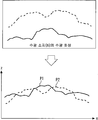
도 3은 수광 소자(6) 및 수광 소자(7)에 의해 취득된 수광 화상의 처리 방법을 나타내는 도면이다. 도 3의 상단은, 수광 소자(6)의 수광 화상과 수광 소자(7)의 수광 화상을 나타낸다. 도 3의 하단은, 수광 소자(6)의 수광 화상으로부터 변환된 제 1 표면 데이터 P1과 수광 소자(7)의 수광 화상으로부터 변환된 제 2 표면 데이터 P2를 나타낸다. 도 3의 하단의 가로축은, 제 1 표면 데이터 P1 및 제 2 표면 데이터 P2가 x 방향으로 각각 복수 개의 데이터를 포함하는 것을 나타낸다. 표면 데이터가 포함하는 데이터의 개수는 임의로 결정된다.3 is a diagram illustrating a method of processing a light received image obtained by the
본 실시의 형태에 나타내는 예에서는, 제어 장치(3)는, 센서 헤드(2)에 의해 취득된 제 1 표면 데이터 및 제 2 표면 데이터에 근거하여, 로프(1)에 발생한 피치 이상을 검출한다. 즉, 제어 장치(3)는, 긴 물체의 표면에 형성된 모양의 주기 이상을 검출한다. 도 1은 제어 장치(3)가 신호선(8)에 의해 센서 헤드(2)에 접속되는 예를 나타낸다. 센서 헤드(2)와 제어 장치(3)를 동일한 하우징 내에 배치하더라도 좋다. 제어 장치(3)가 갖는 기능의 일부를 센서 헤드(2)가 구비하더라도 좋다.In the example shown in this embodiment, the
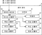
도 4는 제어 장치(3)의 예를 나타내는 도면이다. 제어 장치(3)는, 예컨대 기억부(9), 데이터 처리부(10), 유사도 산출부(11), 위상 산출부(12), 주기 산출부(13) 및 이상 검출부(14)를 구비한다.4 is a diagram illustrating an example of the
기억부(9)에 2개의 레퍼런스 데이터가 기억된다. 이하의 설명에서는, 기억부(9)에 기억된 한쪽의 레퍼런스 데이터를 제 1 레퍼런스 데이터라고 표기한다. 기억부(9)에 기억된 또 한쪽의 레퍼런스 데이터를 제 2 레퍼런스 데이터라고 표기한다.Two reference data are stored in the
데이터 처리부(10)는, 센서 헤드(2)로부터 수신한 제 1 표면 데이터를 가공하고, 가공한 데이터를 최종적인 제 1 표면 데이터로서 출력한다. 데이터 처리부(10)는, 센서 헤드(2)로부터 수신한 제 2 표면 데이터를 가공하고, 가공한 데이터를 최종적인 제 2 표면 데이터로서 출력한다. 본 실시의 형태에 나타내는 예에서는, 데이터 처리부(10)는, 긴 물체의 표면 데이터를 취득하는 수단의 일부를 구성한다. 로프(1)의 피치 이상을 검출하는데 있어서는, 센서 헤드(2)에 의해 취득된 표면 데이터로부터 특정 주파수 성분을 제거한 데이터를 최종적인 표면 데이터로서 채용하는 것이 바람직하다. 이와 같은 데이터 처리를 행하는 것에 의해, 로프(1)가 표면에 갖는 주기적인 모양의 성분을 강조할 수 있다.The
도 5는 데이터 처리부(10)의 기능을 설명하기 위한 도면이다. 도 5는 데이터 처리부(10)에 의한 데이터 처리가 행하여진 후의 제 1 표면 데이터 P1 및 제 2 표면 데이터 P2를 나타낸다. 데이터 처리부(10)는, 예컨대, 도 3에 나타내는 제 1 표면 데이터 P1에 대하여 저주파 성분 제거 처리를 행하는 것에 의해 도 5에 나타내는 제 1 표면 데이터 P1을 취득한다. 데이터 처리부(10)는, 예컨대, 도 3에 나타내는 제 2 표면 데이터 P2에 대하여 저주파 성분 제거 처리를 행하는 것에 의해 도 5에 나타내는 제 2 표면 데이터 P2를 취득한다. 도 5에 나타내는 예에서는, 도 3에 나타내는 제 1 표면 데이터 P1 및 제 2 표면 데이터 P2로부터, 로프(1)의 지름의 영향이 제거되어 있다.5 is a diagram for explaining the function of the
데이터 처리부(10)의 기능은, 센서 헤드(2)에 구비되더라도 좋다. 또한, 긴 물체의 표면 데이터를 취득하는 수단은, 데이터 처리부(10)의 기능을 구비하고 있지 않더라도 좋다. 본 실시의 형태에 나타내는 예에서는, 데이터 처리부(10)로부터의 출력이 긴 물체의 표면 데이터를 취득하는 수단으로부터의 최종적인 출력이 된다. 데이터 처리부(10)가 구비되어 있지 않으면, 센서 헤드(2)로부터의 출력이 긴 물체의 표면 데이터를 취득하는 수단으로부터의 최종적인 출력이 된다.The function of the
광원(4) 및 광원(5)으로부터는 동시에 광이 출력된다. 시각 t에 위치 L1에서 취득된 제 1 표면 데이터 P1은, P(t, L1)로 표기할 수 있다. 동일한 시각 t에 위치 L2에서 취득된 제 2 표면 데이터 P2는, P(t, L2)로 표기할 수 있다. 제 1 표면 데이터 P(t, L1) 및 제 2 표면 데이터 P(t, L2)는, 하기와 같이 n행 1열의 행렬로 표기할 수 있다. n은, 예컨대 2 이상의 정수이다. 도 5는 n=150인 예를 나타낸다.Light is simultaneously output from the

도 6은 레퍼런스 데이터의 예를 나타내는 도면이다. 상술한 바와 같이, 로프(1)는, 표면에 주기적인 모양을 갖는다. 예컨대, 로프(1)의 표면에 형성된 모양의 주기와 동일한 주기를 갖는 정현파가 제 1 레퍼런스 데이터로서 기억부(9)에 기억된다. 로프(1)의 표면에 형성된 모양의 주기와 동일한 주기를 갖는 여현파가 제 2 레퍼런스 데이터로서 기억부(9)에 기억된다. 제 1 레퍼런스 데이터 Ref1 및 제 2 레퍼런스 데이터 Ref2는, 하기와 같이 n행 1열의 행렬로 표기할 수 있다. 도 6은 n=150인 예를 나타낸다.6 is a diagram illustrating an example of reference data. As mentioned above, the

본 실시의 형태에서는, 제 1 표면 데이터 P(t, L1), 제 2 표면 데이터 P(t, L2), 제 1 레퍼런스 데이터 Ref1 및 제 2 레퍼런스 데이터 Ref2가 다차원의 벡터 데이터, 즉 요소 수 n의 벡터인 예에 대하여 설명한다. 제 1 레퍼런스 데이터 Ref1과 제 2 레퍼런스 데이터 Ref2의 내적은, 도 6에 나타내는 예와 같이 0인 것이 바람직하다. 도 6에 나타내는 제 1 레퍼런스 데이터 Ref1과 제 2 레퍼런스 데이터 Ref2는 직교 관계에 있는 정현파이다. 단, 제 1 레퍼런스 데이터 Ref1과 제 2 레퍼런스 데이터 Ref2의 내적은 0이 아니더라도 좋다. 제 1 레퍼런스 데이터 Ref1 및 제 2 레퍼런스 데이터 Ref2는, 도 6에 나타내는 예로 한정되지 않는다.In the present embodiment, the first surface data P (t, L1), the second surface data P (t, L2), the first reference data Ref1 and the second reference data Ref2 are multidimensional vector data, that is, the number of elements n The example which is a vector is demonstrated. It is preferable that the inner product of the 1st reference data Ref1 and the 2nd reference data Ref2 is 0 like the example shown in FIG. The first reference data Ref1 and the second reference data Ref2 shown in FIG. 6 are sine waves in orthogonal relationship. However, the inner product of the first reference data Ref1 and the second reference data Ref2 may not be zero. The first reference data Ref1 and the second reference data Ref2 are not limited to the examples shown in FIG. 6.
유사도 산출부(11)는, 표면 데이터와 레퍼런스 데이터의 유사도를 산출한다. 예컨대, 유사도 산출부(11)는, 제 1 유사도, 제 2 유사도, 제 3 유사도 및 제 4 유사도를 산출한다. 제 1 유사도는, 데이터 처리부(10)로부터 출력된 제 1 표면 데이터와 기억부(9)에 기억된 제 1 레퍼런스 데이터의 유사도이다. 제 2 유사도는, 데이터 처리부(10)로부터 출력된 제 1 표면 데이터와 기억부(9)에 기억된 제 2 레퍼런스 데이터의 유사도이다. 제 3 유사도는, 데이터 처리부(10)로부터 출력된 제 2 표면 데이터와 기억부(9)에 기억된 제 1 레퍼런스 데이터의 유사도이다. 제 4 유사도는, 데이터 처리부(10)로부터 출력된 제 2 표면 데이터와 기억부(9)에 기억된 제 2 레퍼런스 데이터의 유사도이다.The
예컨대, 유사도 산출부(11)는, 제 1 표면 데이터 P(t, L1)과 제 1 레퍼런스 데이터 Ref1의 상관 계수 ρ1(t, L1)을 제 1 유사도로서 산출한다. 유사도 산출부(11)는, 제 1 표면 데이터 P(t, L1)과 제 2 레퍼런스 데이터 Ref2의 상관 계수 ρ2(t, L1)을 제 2 유사도로서 산출한다. 유사도 산출부(11)는, 제 2 표면 데이터 P(t, L2)와 제 1 레퍼런스 데이터 Ref1의 상관 계수 ρ1(t, L2)를 제 3 유사도로서 산출한다. 유사도 산출부(11)는, 제 2 표면 데이터 P(t, L2)와 제 2 레퍼런스 데이터 Ref2의 상관 계수 ρ2(t, L2)를 제 4 유사도로서 산출한다.For example, the
도 7은 위상 산출부(12)의 기능을 설명하기 위한 도면이다. 위상 산출부(12)는, 유사도 벡터 S의 편각을 위상 θ로서 산출한다. 본 실시의 형태에 나타내는 예에서는, 위상 산출부(12)는, 제 1 표면 데이터에 관한 유사도 벡터 S(t, L1)의 위상 θ(t, L1)을 산출한다. 유사도 벡터 S(t, L1)은, 유사도 산출부(11)에 의해 산출된 상관 계수 ρ1(t, L1)과 상관 계수 ρ2(t, L1)을 요소로 하는 벡터이다. 위상 θ(t, L1)은, 유사도 벡터 S(t, L1)의 편각이다. 또한, 위상 산출부(12)는, 제 2 표면 데이터에 관한 유사도 벡터 S(t, L2)의 위상 θ(t, L2)를 산출한다. 유사도 벡터 S(t, L2)는, 유사도 산출부(11)에 의해 산출된 상관 계수 ρ1(t, L2)와 상관 계수 ρ2(t, L2)를 요소로 하는 벡터이다. 위상 θ(t, L2)는, 유사도 벡터 S(t, L2)의 편각이다.7 is a diagram for explaining the function of the
도 7은 제 1 레퍼런스 데이터 Ref1과의 유사도를 가로축으로 하고, 제 2 레퍼런스 데이터 Ref2와의 유사도를 세로축으로 한 직교 평면 상에, 유사도 벡터 S(t, L1) 및 유사도 벡터 S(t, L2)를 플롯한 예를 나타낸다. 예컨대, 로프(1)가 -y 방향으로 이동하면, 유사도 벡터 S(t, L1) 및 유사도 벡터 S(t, L2)는, 도 7에 나타내는 B 방향으로 회전한다. 유사도 벡터 S(t, L1)의 궤적은, 반경이 최대 1이 되는 원 형상이다. 마찬가지로, 유사도 벡터 S(t, L2)의 궤적은, 반경이 최대 1이 되는 원 형상이다. 로프(1)가 1스트랜드 피치분의 거리만큼 이동하면, 유사도 벡터 S(t, L1) 및 유사도 벡터 S(t, L2)는 1회전한다.FIG. 7 shows a similarity vector S (t, L1) and a similarity vector S (t, L2) on an orthogonal plane having a horizontal axis of similarity with the first reference data Ref1 and a vertical axis of similarity with the second reference data Ref2. The plotted example is shown. For example, when the
주기 산출부(13)는, 로프(1)의 표면에 형성된 모양의 주기를 산출한다. 본 실시의 형태에 나타내는 예에서는, 상술한 바와 같이, 상기 주기는 로프(1)의 스트랜드 피치에 일치한다. 도 7에 나타내는 바와 같이, 유사도 벡터 S의 시점은 원점이다. 유사도 벡터 S의 종점은, 그 유사도 벡터의 요소, 즉 유사도 산출부(11)에 의해 산출된 2개의 유사도를 좌표로 하는 점이다. 위상 θ는, 유사도 벡터 S의 방향을 나타낸다. 주기 산출부(13)는, 로프(1)의 스트랜드 피치 SP를 다음 식에 의해 산출할 수 있다.The
![]()
![]()
위의 식에 나타내는 바와 같이, 주기 산출부(13)는, 위상 산출부(12)에 의해 산출된 위상 θ(t, L1)과 위상 θ(t, L2)에 근거하여, 스트랜드 피치 SP를 산출한다. 예컨대, 주기 산출부(13)는, y축 방향의 위치 변화에 대응한 위상의 위치적 변화율을 산출하는 것에 의해, 스트랜드 피치 SP를 구한다.As shown in the above equation, the
이상 검출부(14)는, 로프(1)에 발생한 이상을 검출한다. 이상 검출부(14)는, 예컨대 주기 산출부(13)에 의해 산출된 주기에 근거하여, 긴 물체에 형성된 모양의 주기 이상을 검출한다. 예컨대, 기억부(9)에, 모양의 주기가 정상인 것을 판정하기 위한 기준 범위가 미리 기억된다. 이상 검출부(14)는, 주기 산출부(13)에 의해 산출된 주기가 상기 기준 범위에 들어가 있으면, 로프(1)에 피치 이상이 발생하고 있지 않다고 판정한다. 이상 검출부(14)는, 주기 산출부(13)에 의해 산출된 주기가 상기 기준 범위에 들어가 있지 않으면, 로프(1)에 피치 이상이 발생하고 있다고 판정한다.The
도 8은 본 발명의 실시의 형태 1에 있어서의 검출 장치의 동작의 예를 나타내는 플로차트이다. 도 8은 상술한 처리 흐름을 나타낸다. 이상 검출부(14)에 의해 피치 이상이 검출되면, 제어 장치(3)로부터 경보를 발하더라도 좋다.8 is a flowchart showing an example of the operation of the detection apparatus according to the first embodiment of the present invention. 8 shows the above-described processing flow. When a pitch abnormality is detected by the
본 실시의 형태에 나타내는 예이면, 로프(1)의 이동 속도가 변동하고 있는 경우에도, 로프(1)의 이상을 검출할 수 있다. 본 검출 장치는, 노이즈 내성이 높다고 하는 이점도 있다.In the example shown in this embodiment, even when the moving speed of the
이하에, 본 검출 장치가 구비하는 것이 가능한 다른 기능에 대하여 설명한다.Below, the other function which this detection apparatus can comprise is demonstrated.
제어 장치(3)는, 속도 산출부(15) 및 위치 산출부(16)를 더 구비하더라도 좋다. 속도 산출부(15)는, 로프(1)가 이동하는 속도를 산출한다. 속도 산출부(15)는, 시각 t에 있어서의 로프(1)의 이동 속도 V를 다음 식에 의해 산출할 수 있다.The

도 8에 나타내는 동작은, 예컨대 일정한 주기로 반복하여 행하여진다. 위의 식에 나타내는 Δt는, 표면 데이터를 취득하는 시간 간격이다. 위의 식에 나타내는 바와 같이, 속도 산출부(15)는, 위상 산출부(12)에 의해 산출된 위상 θ(t, L1)과 위상 θ(t, L2)에 근거하여, 로프(1)의 이동 속도를 산출한다. 예컨대, 속도 산출부(15)는, 위상 θ(t, L1) 혹은 위상 θ(t, L2)의 시간 경과에 따른 변화를 산출하는 것에 의해, 로프(1)의 이동 속도를 구한다.The operation shown in FIG. 8 is repeatedly performed at regular intervals, for example. Δt shown in the above equation is a time interval for acquiring surface data. As shown in the above equation, the
위치 산출부(16)는, 로프(1)에 발생한 이상의 위치를 산출한다. 위치 산출부(16)는, 속도 산출부(15)에 의해 산출된 로프(1)의 이동 속도 V에 근거하여, 상기 위치의 산출을 행한다. 예컨대, 위치 산출부(16)는, 속도 산출부(15)에 의해 산출된 로프(1)의 이동 속도 V를 적분하는 것에 의해, 표면 데이터의 취득 개시 위치로부터 로프(1)가 얼마나 이동했는지를 특정할 수 있다. 위치 산출부(16)는, 이상 검출부(14)에 의해 이상이 검출되었을 때의 이동 거리에 근거하여, 검출된 이상의 로프(1) 상의 위치를 산출한다. 상기 산출 방법이면, 로프(1)의 스트랜드 피치가 미지이거나 변동하거나 하더라도, 위치의 산출이 가능하다.The
제어 장치(3)는, 무효부(17)를 더 구비하더라도 좋다. 무효부(17)는, 이상 검출부(14)에 의한 이상 검출을 무효로 한다. 도 7에 나타내는 바와 같이, 유사도 벡터 S(t, L1)의 궤적은 원 형상이다. 복수의 스트랜드가 꼬아 합쳐지는 것에 의해 형성되는 요철이 로프(1)의 표면에 깔끔하게 늘어서 있으면, 유사도 벡터 S(t, L1)의 궤적은, 원점을 중심으로 한 동일한 원을 계속 그린다.The
한편, 제어 장치(3)가 받는 신호에 무시할 수 없는 큰 노이즈가 포함되는 등 하여, 신호 전송에 이상이 발생하면, 유사도 벡터 S(t, L1)의 궤적은 원점에 가까워지도록 변화한다. 이 때문에, 유사도 벡터 S(t, L1)의 놈(norm)에 대하여 미리 정상 범위를 설정하여 두면, 취득된 표면 데이터의 신뢰성이 낮아진 것을 검출할 수 있다. 상기 정상 범위는, 예컨대 0.3으로부터 1로 설정된다. 마찬가지의 것은, 유사도 벡터 S(t, L2)에 관해서도 말할 수 있다.On the other hand, when an abnormality occurs in signal transmission, for example, when the signal received by the
예컨대, 무효부(17)는, 유사도 벡터 S(t, L1)의 놈에 근거하여, 이상 검출부(14)가 이상을 검출하는 기능을 무효로 한다. 무효부(17)는, 유사도 벡터 S(t, L1)의 놈이 상기 정상 범위로부터 벗어나 있으면, 이상 검출부(14)에 의해 이상이 검출되지 않도록 한다. 무효부(17)는, 유사도 벡터 S(t, L2)의 놈에 근거하여, 이상 검출부(14)가 이상을 검출하는 기능을 무효로 하더라도 좋다. 예컨대, 무효부(17)는, 유사도 벡터 S(t, L2)의 놈이 상기 정상 범위로부터 벗어나 있으면, 이상 검출부(14)에 의해 이상이 검출되지 않도록 한다. 무효부(17)는, 유사도 벡터 S(t, L1)의 놈 및 유사도 벡터 S(t, L2)의 놈의 양쪽이 상기 정상 범위로부터 벗어나 있는 경우에, 이상 검출부(14)에 의한 이상 검출을 무효로 하더라도 좋다.For example, the
무효부(17)에 의해 이상 검출부(14)에 의한 이상 검출 기능이 무효로 되어 있는 동안, 위치 산출부(16)는, 직전에 산출된 스트랜드 피치 SP를 이용하여 로프(1)의 이동 거리를 산출하더라도 좋다. 이것에 의해, 적절한 보간이 가능하게 된다.While the abnormality detection function by the
제어 장치(3)는, 이상 검출부(18)를 더 구비하더라도 좋다. 이상 검출부(18)는, 이상 검출부(14)가 검출하는 이상과는 상이한 로프(1)의 이상을 검출한다. 예컨대, 이상 검출부(18)는, 로프(1)의 표면에 형성된 모양의 이상을 검출한다.The
상술한 바와 같이, 유사도 벡터 S(t, L1)의 궤적은 원 형상이다. 신호 전송에 이상이 발생하고 있지 않은 경우, 복수의 스트랜드가 꼬아 합쳐지는 것에 의해 형성되는 요철이 로프(1)의 표면에 깔끔하게 늘어서 있으면, 유사도 벡터 S(t, L1)의 궤적은, 원점을 중심으로 한 동일한 원을 계속 그린다. 한편, 스트랜드의 간격이 불균일하게 되는 등 하여, 꼬임에 불량이 발생하면, 유사도 벡터 S(t, L1)의 궤적은 원점에 가까워지도록 변화한다. 이 때문에, 유사도 벡터 S(t, L1)의 놈에 대하여 미리 정상 범위를 설정하여 두면, 로프(1)의 표면에 형성된 모양에 이상이 발생하고 있는 것을 검출할 수 있다. 상기 정상 범위는, 예컨대 0.6으로부터 1로 설정된다. 마찬가지의 것은, 유사도 벡터 S(t, L2)에 관해서도 말할 수 있다.As described above, the trajectory of the similarity vector S (t, L1) is circular. When no abnormality occurs in signal transmission, if the unevenness formed by the twisting of the plurality of strands is neatly arranged on the surface of the
예컨대, 이상 검출부(18)는, 유사도 벡터 S(t, L1)의 놈에 근거하여, 로프(1)의 모양에 이상이 발생한 것을 검출한다. 이상 검출부(18)는, 유사도 벡터 S(t, L1)의 놈이 상기 정상 범위로부터 벗어나 있으면, 로프(1)의 모양에 이상이 발생한 것을 검출한다. 본 실시의 형태에 나타내는 예이면, 이상 검출부(18)는, 로프(1)의 형상 이상을 검출한다. 이상 검출부(18)는, 유사도 벡터 S(t, L2)의 놈에 근거하여, 로프(1)의 모양에 이상이 발생한 것을 검출하더라도 좋다. 예컨대, 이상 검출부(18)는, 유사도 벡터 S(t, L2)의 놈이 상기 정상 범위로부터 벗어나 있으면, 로프(1)의 형상 이상을 검출한다. 이상 검출부(18)는, 유사도 벡터 S(t, L1)의 놈 및 유사도 벡터 S(t, L2)의 놈의 양쪽이 상기 정상 범위로부터 벗어나 있는 경우에, 로프(1)의 형상 이상을 검출하더라도 좋다.For example, the
이상 검출부(18)에 의해 모양의 이상이 검출된 경우에, 그 이상을 확인할 수 있는 데이터를 기억부(9)에 기억시키더라도 좋다. 예컨대, 이상 검출부(18)에 의해 모양의 이상이 검출되면, 그 이상을 검출하기 위해 사용된 표면 데이터를 기억부(9)에 기억시킨다. 후술하지만, 센서 헤드(2)는, 표면 데이터를 취득하기 위해 카메라를 구비하더라도 좋다. 이상 검출부(18)에 의해 모양의 이상이 검출된 경우에, 카메라에 의해 촬영된 화상 데이터를 기억부(9)에 기억시키더라도 좋다.When abnormality of a pattern is detected by the
도 9는 센서 헤드(2)의 다른 예를 설명하기 위한 도면이다. 도 9에 나타내는 센서 헤드(2)는, 예컨대 광원(4), 광원(5) 및 수광 소자(6)를 구비한다. 도 9는 로프(1)의 표면에서 반사된 광원(4)으로부터의 광과 로프(1)의 표면에서 반사된 광원(5)으로부터의 광의 양쪽을 1개의 수광 소자(6)로 받는 예를 나타낸다. 도 9에 나타내는 예에서는, 광원(5)은, 광원(4)으로부터의 광의 파장과는 상이한 파장의 광을 로프(1)에 부딪치게 하는 것이 바람직하다.9 is a diagram for explaining another example of the
도 10은 수광 소자(6)에 의해 취득된 수광 화상의 처리 방법을 나타내는 도면이다. 도 10의 상단은, 수광 소자(6)의 수광 화상을 나타낸다. 도 10의 하단은, 수광 소자(6)의 수광 화상으로부터 변환된 제 1 표면 데이터 P1 및 제 2 표면 데이터 P2를 나타낸다. 도 10의 하단의 가로축은, 제 1 표면 데이터 P1 및 제 2 표면 데이터 P2가 x 방향으로 각각 복수 개의 데이터를 포함하는 것을 나타낸다. 표면 데이터가 포함하는 데이터의 개수는 임의로 결정된다.10 is a diagram illustrating a method of processing a light received image acquired by the
도 9 및 도 10에 나타내는 예이면, 센서 헤드(2)에 복수의 수광 소자를 구비할 필요가 없다. 또한, 광원(4)으로부터의 광의 파장과 광원(5)으로부터의 광의 파장이 상이하면, 표면 데이터의 추출 처리를 용이하게 행할 수 있다.In the example shown in FIG. 9 and FIG. 10, the
센서 헤드(2)는, 광학식의 프로파일 측정기로 한정되지 않는다. 도 11 및 도 12는 센서 헤드(2)의 다른 예를 설명하기 위한 도면이다. 도 11 및 도 12에 나타내는 센서 헤드(2)는, 예컨대 카메라(20)를 구비한다. 센서 헤드(2)는, 카메라(20)에 의해 로프(1)의 표면을 촬영한 화상 데이터로부터 얻어지는 데이터를 표면 데이터로서 취득하더라도 좋다.The
카메라(20)에 의해 촬영된 화상 데이터에는, 높이에 관한 정보가 포함되지 않는다. 센서 헤드(2)는, 로프(1)의 표면에 부여된 색 및 색의 농담을 나타내는 데이터를 표면 데이터로서 취득하더라도 좋다. 예컨대, 센서 헤드(2)는, 로프(1)의 표면 중 x1≤x≤xr 및 L1≤y≤LM의 범위에 부여된 색 및 색의 농담을 나타내는 데이터를 취득한다. 이 데이터는, M개의 표면 데이터에 상당한다. 센서 헤드(2)는, M개의 표면 데이터 중에서, 미리 설정된 2개의 표면 데이터를 제 1 표면 데이터 및 제 2 표면 데이터로서 출력한다.The image data photographed by the
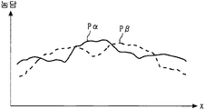
도 13은 카메라(20)에 의해 촬영된 화상 데이터의 처리 방법을 나타내는 도면이다. 도 13은 로프(1) 중 y=Lα의 위치를 통과하는 부분의 표면에 부여된 색 및 색의 농담을 나타내는 데이터를 제 1 표면 데이터 Pα로서 취득하는 예를 나타낸다. 마찬가지로, 도 13은 로프(1) 중 y=Lβ의 위치를 통과하는 부분의 표면에 부여된 색 및 색의 농담을 나타내는 데이터를 제 2 표면 데이터 Pβ로서 취득하는 예를 나타낸다.13 is a diagram illustrating a processing method of image data photographed by the
실시의 형태 2.
본 실시의 형태에서는, 스트랜드 피치 SP의 산출 정밀도를 향상시키기 위한 예에 대하여 설명한다. 본 실시의 형태에 있어서의 검출 장치는, 예컨대 도 11에 나타내는 예와 마찬가지이다. 검출 장치는, 예컨대 센서 헤드(2)와 제어 장치(3)를 구비한다. 센서 헤드(2)는, 예컨대 카메라(20)를 구비한다.In this embodiment, an example for improving the calculation accuracy of strand pitch SP is demonstrated. The detection apparatus in this embodiment is the same as the example shown in FIG. 11, for example. The detection device includes, for example, a
센서 헤드(2)는, 예컨대, 로프(1)의 표면에 부여된 색 및 색의 농담을 나타내는 데이터를 표면 데이터로서 취득한다. 센서 헤드(2)는, 카메라(20)에 의해 취득된 화상 데이터로부터 M개의 표면 데이터를 취득한다. M은, 예컨대 3 이상의 자연수이다.The
도 14는 본 발명의 실시의 형태 2에 있어서의 제어 장치(3)의 예를 나타내는 도면이다. 도 14에 나타내는 예에서는, 제어 장치(3)는, 기억부(9), 데이터 처리부(10), 선택부(19), 유사도 산출부(11), 위상 산출부(12), 주기 산출부(13) 및 이상 검출부(14)를 구비한다. 제어 장치(3)는, 데이터 처리부(10)를 구비하지 않더라도 좋다. 제어 장치(3)는, 속도 산출부(15), 위치 산출부(16), 무효부(17) 및 이상 검출부(18)를 더 구비하더라도 좋다.FIG. 14: is a figure which shows the example of the
기억부(9)에, 제 1 레퍼런스 데이터 Ref1 및 제 2 레퍼런스 데이터 Ref2가 기억된다. 예컨대, 제 1 레퍼런스 데이터 Ref1은 n행 1열의 행렬로 표기할 수 있다. 제 2 레퍼런스 데이터 Ref2는 n행 1열의 행렬로 표기할 수 있다.The first reference data Ref1 and the second reference data Ref2 are stored in the
데이터 처리부(10)는, 센서 헤드(2)로부터 수신한 각 표면 데이터를, 레퍼런스 데이터와 비교 가능한 표면 데이터로 가공한다. 예컨대, 데이터 처리부(10)는, 센서 헤드(2)로부터 수신한 표면 데이터의 각각에 대하여, 바이어스 제거 처리를 행한다. 데이터 처리부(10)로부터는, 예컨대 바이어스 제거 처리가 행하여진 M개의 표면 데이터 P(t, L1), P(t, L2), …, P(t, LM)이 출력된다. 표면 데이터 P(t, L1)은, 로프(1) 중 시각 t에 y=L1을 통과하는 부분의 표면에 부여된 색 및 색의 농담을 나타내는 데이터이다. 표면 데이터 P(t, L2)는, 로프(1) 중 시각 t에 y=L2를 통과하는 부분의 표면에 부여된 색 및 색의 농담을 나타내는 데이터이다. 표면 데이터 P(t, LM)은, 로프(1) 중 시각 t에 y=LM을 통과하는 부분의 표면에 부여된 색 및 색의 농담을 나타내는 데이터이다. L1로부터 LM의 값은 미리 설정된다.The
선택부(19)는, 데이터 처리부(10)로부터 출력된 M개의 표면 데이터 중에서, 미리 설정된 조건에 근거하여, 제 1 표면 데이터 P(t, Lα)와 제 2 표면 데이터 P(t, Lβ)를 선택한다.The
유사도 산출부(11)는, 선택부(19)에 의해 선택된 표면 데이터와 레퍼런스 데이터의 유사도를 산출한다. 즉, 유사도 산출부(11)는, 제 1 유사도, 제 2 유사도, 제 3 유사도 및 제 4 유사도를 산출한다. 제 1 유사도는, 선택부(19)에 의해 선택된 제 1 표면 데이터와 기억부(9)에 기억된 제 1 레퍼런스 데이터의 유사도이다. 제 2 유사도는, 선택부(19)에 의해 선택된 제 1 표면 데이터와 기억부(9)에 기억된 제 2 레퍼런스 데이터의 유사도이다. 제 3 유사도는, 선택부(19)에 의해 선택된 제 2 표면 데이터와 기억부(9)에 기억된 제 1 레퍼런스 데이터의 유사도이다. 제 4 유사도는, 선택부(19)에 의해 선택된 제 2 표면 데이터와 기억부(9)에 기억된 제 2 레퍼런스 데이터의 유사도이다.The
위상 산출부(12)의 기능은 실시의 형태 1에서 개시한 기능과 마찬가지이다. 주기 산출부(13)의 기능은 실시의 형태 1에서 개시한 기능과 마찬가지이다. 이상 검출부(14)의 기능은 실시의 형태 1에서 개시한 기능과 마찬가지이다.The function of the
도 15는 본 발명의 실시의 형태 2에 있어서의 검출 장치의 동작의 예를 나타내는 플로차트이다. 상술한 바와 같이, 데이터 처리부(10)로부터는 M개의 표면 데이터가 출력된다(S201). 선택부(19)는, 데이터 처리부(10)로부터 출력된 M개의 표면 데이터 중에서, 제 1 표면 데이터 P(t, Lα)와 제 2 표면 데이터 P(t, Lβ)를 선택한다(S202).15 is a flowchart showing an example of the operation of the detection apparatus according to the second embodiment of the present invention. As described above, M surface data are output from the data processing unit 10 (S201). The selecting
예컨대, 유사도 산출부(11)는, 데이터 처리부(10)로부터 출력된 각 표면 데이터에 대하여, 제 1 레퍼런스 데이터와의 유사도 및 제 2 레퍼런스 데이터와의 유사도를 산출한다. 도 15는 제 1 레퍼런스 데이터와의 유사도로서 상관 계수 ρ1이, 제 2 레퍼런스 데이터와의 유사도로서 상관 계수 ρ2가 산출되는 예를 나타낸다. 다음으로, 각 표면 데이터에 대하여, 상관 계수 ρ1과 상관 계수 ρ2를 요소로 하는 유사도 벡터 S가 산출된다. 또한, 각 표면 데이터에 대하여, 유사도 벡터 S의 놈이 산출된다.For example, the
선택부(19)는, 예컨대 산출된 유사도 벡터 S의 놈에 근거하여, 제 1 표면 데이터 P(t, Lα)와 제 2 표면 데이터 P(t, Lβ)를 선택한다. 도 16은 선택부(19)의 기능을 설명하기 위한 도면이다. 선택부(19)는, 예컨대, 데이터 처리부(10)로부터 출력된 M개의 표면 데이터 중, 유사도 벡터 S의 놈이 가장 큰 것과 2번째로 큰 것을 제 1 표면 데이터 P(t, Lα) 및 제 2 표면 데이터 P(t, Lβ)로서 선택한다. 여기서, Lβ>Lα이다.The
S202에 있어서 제 1 표면 데이터 P(t, Lα) 및 제 2 표면 데이터 P(t, Lβ)가 선택되면, 도 8의 S103으로부터 S106에 나타내는 처리와 마찬가지의 처리가 행하여진다. 도 15에 나타내는 예에서는, S202에 있어서 ρ1(t, Lα), ρ2(t, Lα), ρ1(t, Lβ) 및 ρ2(t, Lβ)가 이미 산출되어 있다. 제 1 표면 데이터 P(t, Lα) 및 제 2 표면 데이터 P(t, Lβ)가 선택부(19)에 의해 선택되면, 위상 산출부(12)는, 유사도 벡터 S(t, Lα)의 위상 θ(t, Lα)를 산출한다(S203). 유사도 벡터 S(t, Lα)는, 유사도 산출부(11)에 의해 산출된 상관 계수 ρ1(t, Lα)와 상관 계수 ρ2(t, Lα)를 요소로 하는 벡터이다. 위상 θ(t, Lα)는, 유사도 벡터 S(t, Lα)의 편각이다. 또한, 위상 산출부(12)는, 유사도 벡터 S(t, Lβ)의 위상 θ(t, Lβ)를 산출한다(S203). 유사도 벡터 S(t, Lβ)는, 유사도 산출부(11)에 의해 산출된 상관 계수 ρ1(t, Lβ)와 상관 계수 ρ2(t, Lβ)를 요소로 하는 벡터이다. 위상 θ(t, Lβ)는, 유사도 벡터 S(t, Lβ)의 편각이다.When the first surface data P (t, Lα) and the second surface data P (t, Lβ) are selected in S202, the same processing as that shown in S103 to S106 in FIG. 8 is performed. In the example shown in FIG. 15, ρ 1 (t, Lα), ρ 2 (t, Lα), ρ 1 (t, Lβ) and ρ 2 (t, Lβ) have already been calculated in S202. When the first surface data P (t, Lα) and the second surface data P (t, Lβ) are selected by the
주기 산출부(13)는, 예컨대 위상 산출부(12)에 의해 산출된 위상 θ(t, Lα)와 위상 θ(t, Lβ)에 근거하여, 다음 식으로부터 스트랜드 피치 SP를 산출한다.The
![]()
![]()
이상 검출부(14)는, 주기 산출부(13)에 의해 산출된 주기에 근거하여, 긴 물체에 형성된 모양의 주기 이상을 검출한다. 예컨대, 이상 검출부(14)는, 주기 산출부(13)에 의해 산출된 주기가 기준 범위로부터 벗어난 경우에, 로프(1)에 피치 이상이 발생하고 있다고 판정한다.The
본 실시의 형태에 나타내는 예이면, 로프(1)의 이동 속도가 변동하고 있는 경우에도, 로프(1)의 이상을 검출할 수 있다. 본 실시의 형태에 나타내는 예이면, 스트랜드 피치 SP의 산출 정밀도를 향상시킬 수 있다.In the example shown in this embodiment, even when the moving speed of the
노이즈의 영향을 적게 하기 위해, 선택부(19)는, 상술한 방법과는 상이한 방법에 의해 제 1 표면 데이터 P(t, Lα)와 제 2 표면 데이터 P(t, Lβ)를 선택하더라도 좋다. 예컨대, 선택부(19)는, 먼저, 데이터 처리부(10)로부터 출력된 M개의 표면 데이터 중, 유사도 벡터 S의 놈이 기준치 이상인 것을 선택한다. 상기 기준치는, 기억부(9)에 미리 기억된다. 예컨대, 기준치는 0.3이다. 선택부(19)는, 유사도 벡터 S의 놈이 기준치 이상인 것 중에서, 이루는 각도가 최대가 되는 2개의 것을 제 1 표면 데이터 P(t, Lα) 및 제 2 표면 데이터 P(t, Lβ)로서 선택한다.In order to reduce the influence of noise, the
본 실시의 형태에서 개시하지 않는 특징에 대해서는, 실시의 형태 1에서 개시된 어느 특징이 채용되더라도 좋다.As for the features not disclosed in the present embodiment, any of the features disclosed in the first embodiment may be employed.
실시의 형태 3.
상술한 바와 같이, 본 검출 장치의 검출 대상이 되는 긴 물체의 예로서, 엘리베이터에서 사용되는 와이어 로프를 들 수 있다. 엘리베이터의 카(car)는, 예컨대 복수 개의 와이어 로프에 의해 승강로에 매달린다. 엘리베이터의 카가 복수 개의 와이어 로프로 매달려 있는 경우, 어느 와이어 로프에 대해서도 동일한 장력이 작용하는 것이 바람직하다.As mentioned above, the wire rope used by an elevator can be mentioned as an example of the long object used as the detection object of this detection apparatus. The car of the elevator is suspended on the hoistway by, for example, a plurality of wire ropes. When the car of the elevator is suspended by a plurality of wire ropes, it is preferable that the same tension is applied to any of the wire ropes.
예컨대, 1개의 와이어 로프에만 큰 장력이 작용하면, 그 와이어 로프에 연신이 발생한다. 연신이 발생한 와이어 로프에서는, 스트랜드 피치가 길어진다. 즉, 당해 와이어 로프에 피치 이상이 발생한다. 본 실시의 형태에서는, 검출 장치가 복수 개의 긴 물체를 검출 대상으로 하는 예에 대하여 설명한다.For example, when a large tension acts on only one wire rope, stretching occurs in the wire rope. In the wire rope in which extending | stretching occurred, strand pitch becomes long. That is, pitch abnormality arises in the said wire rope. In this embodiment, an example in which the detection device uses a plurality of long objects as a detection target will be described.
도 17은 본 발명의 실시의 형태 3에 있어서의 검출 장치의 예를 나타내는 도면이다. 도 18은 도 17에 나타내는 화살표 A의 방향으로부터 긴 물체를 본 도면이다. 도 18은 로프(1)와 평행하게 로프(21)가 배치되어 있는 예를 나타낸다.It is a figure which shows the example of the detection apparatus in
로프(21)는, 로프(1)와 마찬가지로, 긴 방향으로 이동한다. 예컨대, 로프(21)는, +y 방향 혹은 -y 방향으로 이동한다. 로프(21)는, +y 방향 및 -y 방향의 양쪽으로 이동하더라도 좋다. 로프(21)는, 복수의 스트랜드를 구비한다. 로프(21)는, 복수의 스트랜드가 꼬아 합쳐지는 것에 의해 형성된다. 로프(21)는, 로프(1)의 표면에 형성된 모양과 동일한 모양을 표면에 갖는다.The
검출 장치는, 예컨대 센서 헤드(2)와 제어 장치(3)를 구비한다. 센서 헤드(2)는, 예컨대 광원(4) 및 수광 소자(6)를 구비한다. 본 실시의 형태에 나타내는 예에서는, 광원(4)은, 로프(1)의 표면 및 로프(21)의 표면의 양쪽에 대하여 동시에 광을 조사한다. 도 17 및 도 18은 광원(4)이 로프(1)의 긴 방향 및 로프(21)의 긴 방향과 직교하는 방향으로 레이저광을 조사하는 예를 나타낸다. 광원(4)으로부터 조사된 광은, 동일한 높이에서 로프(1) 및 로프(21)에 부딪친다. 도 17 및 도 18에 나타내는 예에서는, 광원(4)으로부터 조사된 광은, 로프(1)를 횡단하도록 로프(1)의 한쪽의 단으로부터 다른 쪽의 단에 걸쳐 직선 형상으로 부딪친다. 마찬가지로, 광원(4)으로부터 조사된 광은, 로프(21)를 횡단하도록 로프(21)의 한쪽의 단으로부터 다른 쪽의 단에 걸쳐 직선 형상으로 부딪친다.The detection device includes, for example, a
수광 소자(6)는, 광원(4)으로부터 조사된 광 중 로프(1)의 표면에서 반사된 광을 수광한다. 또한, 수광 소자(6)는, 광원(4)으로부터 조사된 광 중 로프(21)의 표면에서 반사된 광을 수광한다. 수광 소자(6)는, 광원(4)이 광을 조사하는 방향에 대하여 비스듬하게 배치된다. 수광 소자(6)는, 로프(1)의 표면에서 반사된 광원(4)으로부터의 광 중, 로프(1)의 긴 방향에 대하여 일정한 각도로 비스듬하게 반사된 광을 수광한다. 마찬가지로, 수광 소자(6)는, 로프(21)의 표면에서 반사된 광원(4)으로부터의 광 중, 로프(1)의 긴 방향에 대하여 일정한 각도로 비스듬하게 반사된 광을 수광한다.The
도 17 및 도 18에 나타내는 광 a는, 광원(4)으로부터 로프(1)로 향해 조사된 광이다. 예컨대, 광 a는 y=L1에서 로프(1)의 표면에 부딪친다. 광 b 및 광 c는, 로프(1)의 표면에서 반사된 광 a 중, 수광 소자(6)에 의해 수광되는 각도로 반사된 광이다. 수광 소자(6)가 광 b 및 광 c 등을 수광하는 것에 의해, 센서 헤드(2)는, 로프(1) 중 광원(4)으로부터의 광이 부딪친 부분의 단면 형상을 나타내는 데이터를 제 1 표면 데이터로서 취득한다.Light a shown to FIG. 17 and FIG. 18 is the light irradiated toward the
마찬가지로, 도 17 및 도 18에 나타내는 광 g는, 광원(4)으로부터 로프(21)로 향해 조사된 광이다. 예컨대, 광 g는 y=L1에서 로프(21)의 표면에 부딪친다. 광 h 및 광 i는, 로프(21)의 표면에서 반사된 광 g 중, 수광 소자(6)에 의해 수광되는 각도로 반사된 광이다. 수광 소자(6)가 광 h 및 광 i 등을 수광하는 것에 의해, 센서 헤드(2)는, 로프(21) 중 광원(4)으로부터의 광이 부딪친 부분의 단면 형상을 나타내는 데이터를 제 2 표면 데이터로서 취득한다.Similarly, the light g shown in FIG. 17 and FIG. 18 is light irradiated toward the
도 19는 수광 소자(6)에 의해 취득된 수광 화상의 처리 방법을 나타내는 도면이다. 도 19의 상단은, 수광 소자(6)의 수광 화상을 나타낸다. 도 19의 하단은, 수광 소자(6)의 수광 화상으로부터 변환된 제 1 표면 데이터 P3 및 제 2 표면 데이터 P4를 나타낸다. 도 19의 하단의 가로축은, 제 1 표면 데이터 P3 및 제 2 표면 데이터 P4가 x 방향으로 각각 복수 개의 데이터를 포함하는 것을 나타낸다. 표면 데이터가 포함하는 데이터의 개수는 임의로 결정된다.19 is a diagram illustrating a method of processing a light received image acquired by the
도 20은 제어 장치(3)의 예를 나타내는 도면이다. 제어 장치(3)는, 예컨대 기억부(9), 데이터 처리부(10), 유사도 산출부(11), 위상 산출부(12) 및 이상 검출부(14)를 구비한다. 제어 장치(3)는, 데이터 처리부(10)를 구비하지 않더라도 좋다. 제어 장치(3)는, 무효부(17) 및 이상 검출부(18)를 더 구비하더라도 좋다.20 is a diagram illustrating an example of the
기억부(9)에, 제 1 레퍼런스 데이터 Ref1 및 제 2 레퍼런스 데이터 Ref2가 기억된다. 예컨대, 제 1 레퍼런스 데이터 Ref1은 n행 1열의 행렬로 표기할 수 있다. 제 2 레퍼런스 데이터 Ref2는 n행 1열의 행렬로 표기할 수 있다.The first reference data Ref1 and the second reference data Ref2 are stored in the
데이터 처리부(10)는, 예컨대 센서 헤드(2)로부터 수신한 제 1 표면 데이터를 가공하고, 가공한 데이터를 최종적인 제 1 표면 데이터로서 출력한다. 데이터 처리부(10)는, 예컨대 센서 헤드(2)로부터 수신한 제 2 표면 데이터를 가공하고, 가공한 데이터를 최종적인 제 2 표면 데이터로서 출력한다.The
유사도 산출부(11)는, 표면 데이터와 레퍼런스 데이터의 유사도를 산출한다. 예컨대, 유사도 산출부(11)는, 데이터 처리부(10)로부터 출력된 제 1 표면 데이터 P3(t, L1)과 제 1 레퍼런스 데이터 Ref1의 상관 계수 ρ1(t, L1(P3))을 제 1 유사도로서 산출한다. 유사도 산출부(11)는, 데이터 처리부(10)로부터 출력된 제 1 표면 데이터 P3(t, L1)과 제 2 레퍼런스 데이터 Ref2의 상관 계수 ρ2(t, L1(P3))을 제 2 유사도로서 산출한다. 유사도 산출부(11)는, 데이터 처리부(10)로부터 출력된 제 2 표면 데이터 P4(t, L1)과 제 1 레퍼런스 데이터 Ref1의 상관 계수 ρ1(t, L1(P4))를 제 3 유사도로서 산출한다. 유사도 산출부(11)는, 데이터 처리부(10)로부터 출력된 제 2 표면 데이터 P4(t, L1)과 제 2 레퍼런스 데이터 Ref2의 상관 계수 ρ2(t, L1(P4))를 제 4 유사도로서 산출한다.The
도 21은 위상 산출부(12)의 기능을 설명하기 위한 도면이다. 위상 산출부(12)는, 유사도 벡터 S의 편각을 위상 θ로서 산출한다. 본 실시의 형태에 나타내는 예에서는, 위상 산출부(12)는, 제 1 표면 데이터에 관한 유사도 벡터 S3(t, L1)의 위상 θ3(t, L1)을 산출한다. 유사도 벡터 S3(t, L1)은, 유사도 산출부(11)에 의해 산출된 상관 계수 ρ1(t, L1(P3))과 상관 계수 ρ2(t, L1(P3))을 요소로 하는 벡터이다. 위상 θ3(t, L1)은, 유사도 벡터 S3(t, L1)의 편각이다. 또한, 위상 산출부(12)는, 제 2 표면 데이터에 관한 유사도 벡터 S4(t, L1)의 위상 θ4(t, L1)을 산출한다. 유사도 벡터 S4(t, L1)은, 유사도 산출부(11)에 의해 산출된 상관 계수 ρ1(t, L1(P4))와 상관 계수 ρ2(t, L1(P4))를 요소로 하는 벡터이다. 위상 θ4(t, L1)은, 유사도 벡터 S4(t, L1)의 편각이다.21 is a diagram for explaining the function of the
엘리베이터의 카가 로프(1) 및 로프(21)에 의해 승강로에 매달려 있는 경우, 로프(1)가 이동하는 속도와 로프(21)가 이동하는 속도는 동일하다. 로프(1)의 스트랜드 피치와 로프(21)의 스트랜드 피치가 동일하면, 유사도 벡터 S3(t, L1)과 유사도 벡터 S4(t, L1)이 이루는 각도는, 상기 속도에 상관없이 일정하게 된다. 유사도 벡터 S3(t, L1)과 유사도 벡터 S4(t, L1)이 이루는 각도는, 위상 θ4(t, L1)과 위상 θ3(t, L1)의 차이, 즉 위상차이다.When the car of the elevator is suspended on the hoistway by the
본 실시의 형태에 나타내는 예에서는, 이상 검출부(14)는, 위상 산출부(12)에 의해 산출된 위상 θ4(t, L1) 및 위상 θ3(t, L1)에 근거하여, 로프(1) 또는 로프(21)에 이상이 발생한 것을 검출한다. 예컨대, 이상 검출부(14)는, 로프(1)의 표면에 형성된 모양 혹은 로프(21)의 표면에 형성된 모양의 주기 이상을 검출한다. 예컨대, 기억부(9)에, 모양의 주기가 정상인 것을 판정하기 위한 기준 범위가 미리 기억된다. 이상 검출부(14)는, 위상 θ4(t, L1)과 위상 θ3(t, L1)의 차이가 상기 기준 범위에 들어가 있으면, 로프(1) 및 로프(21)의 양쪽에 피치 이상이 발생하고 있지 않다고 판정한다. 이상 검출부(14)는, 위상 θ4(t, L1)과 위상 θ3(t, L1)의 차이가 상기 기준 범위에 들어가 있지 않으면, 로프(1) 혹은 로프(21)의 어느 한쪽에 피치 이상이 발생하고 있다고 판정한다.In the example shown in this embodiment, the
본 실시의 형태에 나타내는 예이면, 검출 장치는, 복수 개의 긴 물체를 검출 대상으로 할 수 있다. 또한, 본 실시의 형태에 나타내는 예이면, 로프(1) 및 로프(21)의 이동 속도가 변동하고 있는 경우에도, 이상이 발생한 것을 검출할 수 있다.If it is an example shown in this embodiment, a detection apparatus can make a some long object into a detection object. In addition, if it is an example shown in this embodiment, even if the moving speed of the
본 실시의 형태에 나타내는 예에 있어서 제어 장치(3)가 이상 검출부(18)를 더 구비하는 경우, 이상 검출부(18)는, 유사도 벡터 S3(t, L1)의 놈에 근거하여 로프(1)의 모양에 이상이 발생한 것을 검출한다. 예컨대, 이상 검출부(18)는, 유사도 벡터 S3(t, L1)의 놈이 정상 범위로부터 벗어나 있으면, 로프(1)의 모양에 이상이 발생한 것을 검출한다. 또한, 이상 검출부(18)는, 유사도 벡터 S4(t, L1)의 놈에 근거하여 로프(21)의 모양에 이상이 발생한 것을 검출한다. 예컨대, 이상 검출부(18)는, 유사도 벡터 S4(t, L1)의 놈이 정상 범위로부터 벗어나 있으면, 로프(21)의 모양에 이상이 발생한 것을 검출한다.In the example shown in this embodiment, when the
본 실시의 형태에 나타내는 예에서는, 광원(4)으로부터 조사된 광이 로프(1) 및 로프(21)에 동일한 높이에서 부딪치는 예에 대하여 설명했다. 센서 헤드(2)가 상이한 높이의 표면 데이터를 취득할 수 있으면, 본 실시의 형태에 나타내는 예에 있어서도, 제어 장치(3)는, 주기 산출부(13), 속도 산출부(15) 및 위치 산출부(16)를 더 구비하더라도 좋다.In the example shown in this embodiment, the example which the light irradiated from the
이러한 경우, 센서 헤드(2)는, 예컨대 광원(4), 광원(5), 수광 소자(6) 및 수광 소자(7)를 구비한다. 광원(4)은, 로프(1)의 표면에 광을 조사한다. 수광 소자(6)는, 광원(4)으로부터 조사된 광 중 로프(1)의 표면에서 반사된 광을 수광한다. 광원(5)은, 로프(21)의 표면에 광을 조사한다. 광원(5)으로부터 조사된 광은, 광원(4)으로부터의 광이 로프(1)에 부딪치는 위치로부터 y축 방향으로 일정 거리만큼 떨어진 위치에서 로프(21)에 부딪친다. 수광 소자(7)는, 광원(5)으로부터 조사된 광 중 로프(21)의 표면에서 반사된 광을 수광한다. 센서 헤드(2)는, 카메라(20)를 구비하더라도 좋다.In this case, the
또한, 속도 산출부(15)는, 위상 산출부(12)에 의해 산출된 위상 θ(t, L1)과 위상 θ(t, L2)에 근거하여, 로프(1) 및 로프(21)의 이동 속도를 산출한다. 이 예에 있어서, L2는, 광원(5)으로부터의 광이 로프(21)에 부딪치는 높이를 나타낸다. 위치 산출부(16)는, 이상 검출부(14)에 의해 이상이 검출되었을 때의 이동 거리에 근거하여, 검출된 이상의 로프(1) 상의 위치 혹은 로프(21) 상의 위치를 산출한다.In addition, the
본 실시의 형태에서 개시하지 않는 특징에 대해서는, 실시의 형태 1 또는 2에서 개시된 어느 특징이 채용되더라도 좋다.As for the features not disclosed in this embodiment, any of the features disclosed in
실시의 형태 4.
본 검출 장치가 적용 가능한 엘리베이터에는, 카의 속도를 검출하기 위해 조속기가 구비된다. 조속기는, 예컨대 조속 로프, 조속 도르래 및 인코더를 구비한다. 조속 로프는, 조속 도르래에 감겨 있고, 엘리베이터의 카에 연동하여 이동한다. 즉, 카가 이동하면, 조속 로프가 이동한다. 또한, 조속 로프가 이동하면, 조속 도르래가 회전한다. 인코더는, 조속 도르래의 회전 방향 및 회전 각도에 따른 회전 신호를 출력한다. 인코더로부터 출력된 회전 신호는, 카를 제어하기 위해 이용된다.The elevator to which this detection apparatus is applicable is equipped with the governor in order to detect the speed of a car. The governor comprises, for example, a governing rope, a governing pulley and an encoder. The governing rope is wound around the governing pulley and moves in conjunction with the car of the elevator. That is, when the car moves, the governing rope moves. Also, when the governing rope moves, the governing pulley rotates. The encoder outputs a rotation signal in accordance with the rotation direction and the rotation angle of the governing pulley. The rotation signal output from the encoder is used to control the car.
실시의 형태 1로부터 3에 나타내는 예에서는, 속도 산출부(15)가 로프(1)의 이동 속도 V를 산출한다. 엘리베이터의 카가 로프(1)에 의해 매달려 있으면, 로프(1)의 이동 속도 V는 카의 이동 속도에 일치한다. 이 때문에, 엘리베이터에 있어서, 조속기 대신에 속도 산출부(15)를 이용하여 카의 속도를 검출하더라도 좋다. 이러한 경우, 엘리베이터는 조속기를 구비하고 있지 않더라도 좋다. 또한, 엘리베이터에 있어서, 조속기와 함께 속도 산출부(15)를 이용하여 카의 속도를 검출하더라도 좋다.In the example shown to
조속기에서는, 조속 로프와 조속 도르래의 사이에 발생하는 미끄러짐에 의해 검출 오차가 생길 수 있다. 조속기에서는, 조속 도르래의 마모에 의해 검출 오차가 생길 수 있다. 본 검출 장치이면, 표면 데이터의 취득을 비접촉으로 행할 수 있다. 이 때문에, 카의 속도를 정밀하게 검출할 수 있다. 또한, 조속기를 구비할 필요가 없으면, 엘리베이터의 구성을 간소화할 수 있다.In the governor, a detection error may occur due to the slip generated between the governing rope and the governing pulley. In the governor, a detection error may occur due to wear of the governor pulley. With this detection apparatus, surface data can be acquired non-contact. For this reason, the speed of a car can be detected precisely. If the governor does not need to be provided, the configuration of the elevator can be simplified.
부호 9~19에 나타내는 각 부는, 제어 장치(3)가 갖는 기능을 나타낸다. 도 22는 제어 장치(3)의 하드웨어 구성의 예를 나타내는 도면이다. 제어 장치(3)는, 하드웨어 자원으로서, 예컨대 프로세서(22)와 메모리(23)를 포함하는 처리 회로를 구비한다. 기억부(9)가 갖는 기능은 메모리(23)에 의해 실현된다. 제어 장치(3)는, 메모리(23)에 기억된 프로그램을 프로세서(22)에 의해 실행하는 것에 의해, 부호 10~19에 나타내는 각 부의 기능을 실현한다.Each part shown to the code | symbol 9-19 shows the function which the
프로세서(22)는, CPU(Central Processing Unit), 중앙 처리 장치, 처리 장치, 연산 장치, 마이크로프로세서, 마이크로컴퓨터 혹은 DSP라고도 한다. 메모리(23)로서, 반도체 메모리, 자기 디스크, 플렉서블 디스크, 광 디스크, 콤팩트 디스크, 미니 디스크 혹은 DVD를 채용하더라도 좋다. 채용 가능한 반도체 메모리에는, RAM, ROM, 플래시 메모리, EPROM 및 EEPROM 등이 포함된다.The
제어 장치(3)가 갖는 각 기능의 일부 또는 전부를 하드웨어에 의해 실현하더라도 좋다. 제어 장치(3)의 기능을 실현하는 하드웨어로서, 단일 회로, 복합 회로, 프로그램화한 프로세서, 병렬 프로그램화한 프로세서, ASIC, FPGA, 또는 이들의 조합을 채용하더라도 좋다.Some or all of the functions of the
(산업상 이용가능성)(Industrial availability)
본 발명과 관련되는 검출 장치는, 표면에 주기적인 모양을 갖는 긴 물체를 검출의 대상으로 하는 장치에 적용할 수 있다.The detection apparatus which concerns on this invention can be applied to the apparatus which targets a long object which has a periodic shape on a surface.
1 : 로프
2 : 센서 헤드
3 : 제어 장치
4 : 광원
5 : 광원
6 : 수광 소자
7 : 수광 소자
8 : 신호선
9 : 기억부
10 : 데이터 처리부
11 : 유사도 산출부
12 : 위상 산출부
13 : 주기 산출부
14 : 이상 검출부
15 : 속도 산출부
16 : 위치 산출부
17 : 무효부
18 : 이상 검출부
19 : 선택부
20 : 카메라
21 : 로프
22 : 프로세서
23 : 메모리1: rope
2: sensor head
3: control device
4: light source
5: light source
6: light receiving element
7: light receiving element
8: signal line
9: memory
10: data processing unit
11: similarity calculation unit
12: phase calculator
13: cycle calculation unit
14: abnormal detection unit
15: speed calculator
16: position calculation unit
17: invalid part
18: abnormal detection unit
19: selection unit
20: camera
21: rope
22: processor
23: memory
Claims (11)
제 1 레퍼런스 데이터 및 제 2 레퍼런스 데이터를 기억하는 기억 수단과,
상기 데이터 취득 수단에 의해 취득된 제 1 표면 데이터와 상기 제 1 레퍼런스 데이터의 제 1 유사도, 상기 데이터 취득 수단에 의해 취득된 제 1 표면 데이터와 상기 제 2 레퍼런스 데이터의 제 2 유사도, 상기 데이터 취득 수단에 의해 취득된 제 2 표면 데이터와 상기 제 1 레퍼런스 데이터의 제 3 유사도, 및 상기 데이터 취득 수단에 의해 취득된 제 2 표면 데이터와 상기 제 2 레퍼런스 데이터의 제 4 유사도를 산출하는 유사도 산출 수단과,
상기 유사도 산출 수단에 의해 산출된 제 1 유사도 및 제 2 유사도를 요소로 하는 제 1 유사도 벡터의 편각을 제 1 위상으로서 산출하고, 상기 유사도 산출 수단에 의해 산출된 제 3 유사도 및 제 4 유사도를 요소로 하는 제 2 유사도 벡터의 편각을 제 2 위상으로서 산출하는 위상 산출 수단과,
상기 위상 산출 수단에 의해 산출된 제 1 위상 및 제 2 위상에 근거하여, 상기 긴 물체에 형성된 모양의 주기를 산출하는 주기 산출 수단과,
상기 주기 산출 수단에 의해 산출된 주기에 근거하여, 상기 긴 물체의 이상을 검출하는 제 1 이상 검출 수단
을 구비한 검출 장치.
Data acquisition means for acquiring first surface data and second surface data of an elongated object having a periodic shape on the surface;
Storage means for storing the first reference data and the second reference data;
A first similarity degree of the first surface data acquired by the data acquisition means and the first reference data, a second similarity degree of the first surface data acquired by the data acquisition means and the second reference data, and the data acquisition means Similarity calculation means for calculating a third similarity degree of the second surface data acquired by the first reference data and the fourth similarity degree of the second surface data acquired by the data acquiring means and the second reference data;
The declination of the first similarity vector having the first similarity and the second similarity calculated by the similarity calculating means as the first phase is calculated, and the third similarity and the fourth similarity calculated by the similarity calculating means are elements. Phase calculating means for calculating a polarization angle of the second similarity vector as a second phase,
Period calculating means for calculating a period of a shape formed in the elongated object based on the first phase and the second phase calculated by the phase calculating means;
First abnormality detecting means for detecting an abnormality of the long object based on the period calculated by the periodic calculating means
Detection apparatus provided with.
제 1 레퍼런스 데이터 및 제 2 레퍼런스 데이터를 기억하는 기억 수단과,
상기 데이터 취득 수단에 의해 취득된 표면 데이터 중에서 제 1 표면 데이터 및 제 2 표면 데이터를 선택하는 선택 수단과,
상기 선택 수단에 의해 선택된 제 1 표면 데이터와 상기 제 1 레퍼런스 데이터의 제 1 유사도, 상기 선택 수단에 의해 선택된 제 1 표면 데이터와 상기 제 2 레퍼런스 데이터의 제 2 유사도, 상기 선택 수단에 의해 선택된 제 2 표면 데이터와 상기 제 1 레퍼런스 데이터의 제 3 유사도, 및 상기 선택 수단에 의해 선택된 제 2 표면 데이터와 상기 제 2 레퍼런스 데이터의 제 4 유사도를 산출하는 유사도 산출 수단과,
상기 유사도 산출 수단에 의해 산출된 제 1 유사도 및 제 2 유사도를 요소로 하는 제 1 유사도 벡터의 편각을 제 1 위상으로서 산출하고, 상기 유사도 산출 수단에 의해 산출된 제 3 유사도 및 제 4 유사도를 요소로 하는 제 2 유사도 벡터의 편각을 제 2 위상으로서 산출하는 위상 산출 수단과,
상기 위상 산출 수단에 의해 산출된 제 1 위상 및 제 2 위상에 근거하여, 상기 긴 물체에 형성된 모양의 주기를 산출하는 주기 산출 수단과,
상기 주기 산출 수단에 의해 산출된 주기에 근거하여, 상기 긴 물체의 이상을 검출하는 제 1 이상 검출 수단
을 구비한 검출 장치.
Data acquisition means for acquiring a plurality of surface data of a long object having a periodic shape on the surface;
Storage means for storing the first reference data and the second reference data;
Selecting means for selecting first surface data and second surface data from surface data acquired by said data acquiring means;
A first similarity of the first surface data selected by the selection means and the first reference data, a second similarity of the first surface data selected by the selection means and the second reference data, a second selected by the selection means Similarity calculating means for calculating a third similarity degree between surface data and the first reference data, and a fourth similarity degree between the second surface data selected by the selection means and the second reference data;
The declination of the first similarity vector having the first similarity and the second similarity calculated by the similarity calculating means as the first phase is calculated, and the third similarity and the fourth similarity calculated by the similarity calculating means are elements. Phase calculating means for calculating a polarization angle of the second similarity vector as a second phase,
Period calculating means for calculating a period of a shape formed in the elongated object based on the first phase and the second phase calculated by the phase calculating means;
First abnormality detecting means for detecting an abnormality of the long object based on the period calculated by the periodic calculating means
Detection apparatus provided with.
상기 선택 수단은, 상기 데이터 취득 수단에 의해 취득된 표면 데이터 중, 상기 제 1 레퍼런스 데이터와의 유사도 및 상기 제 2 레퍼런스 데이터와의 유사도를 요소로 하는 유사도 벡터의 놈(norm)이 가장 큰 것과 2번째로 큰 것을 제 1 표면 데이터 및 제 2 표면 데이터로서 선택하는 검출 장치.
The method of claim 2,
The selection means is one of the surface data acquired by the data acquiring means, the norm of the similarity vector having the similarity with the first reference data and the similarity with the second reference data being the largest; The detection apparatus which selects a 2nd largest thing as a 1st surface data and a 2nd surface data.
상기 선택 수단은, 상기 데이터 취득 수단에 의해 취득된 표면 데이터 중, 상기 제 1 레퍼런스 데이터와의 유사도 및 상기 제 2 레퍼런스 데이터와의 유사도를 요소로 하는 유사도 벡터의 놈이 기준치 이상인 것 중에서, 이루는 각도가 최대가 되는 2개의 것을 제 1 표면 데이터 및 제 2 표면 데이터로서 선택하는 검출 장치.
The method of claim 2,
The selecting means is an angle to be formed among the surface data acquired by the data acquiring means, in which the norm of the similarity vector having the similarity with the first reference data and the similarity with the second reference data is equal to or greater than a reference value. The detection apparatus which selects two things whose maximum is a maximum as 1st surface data and 2nd surface data.
상기 위상 산출 수단에 의해 산출된 제 1 위상 및 제 2 위상에 근거하여, 상기 긴 물체의 속도를 산출하는 속도 산출 수단과,
상기 속도 산출 수단에 의해 산출된 속도에 근거하여, 상기 제 1 이상 검출 수단에 의해 검출된 이상의 상기 긴 물체 상에서의 위치를 산출하는 위치 산출 수단
을 더 구비한 검출 장치.
The method according to any one of claims 1 to 4,
Speed calculating means for calculating a speed of the long object based on the first phase and the second phase calculated by the phase calculating means;
Position calculating means for calculating a position on the longer object longer than that detected by the first abnormality detecting means based on the velocity calculated by the speed calculating means
Detection apparatus further provided.
상기 유사도 산출 수단에 의해 산출된 제 1 유사도 및 제 2 유사도를 요소로 하는 제 1 유사도 벡터의 놈 또는 상기 유사도 산출 수단에 의해 산출된 제 3 유사도 및 제 4 유사도를 요소로 하는 제 2 유사도 벡터의 놈의 적어도 어느 한쪽에 근거하여, 상기 긴 물체의 모양에 이상이 발생한 것을 검출하는 제 2 이상 검출 수단을 더 구비한 검출 장치.
The method according to any one of claims 1 to 5,
Of the first similarity vector having the first similarity and the second similarity calculated by the similarity calculating means or the second similarity vector having the third similarity and the fourth similarity calculated by the similarity calculating means And a second abnormality detecting means for detecting that an abnormality has occurred in the shape of the long object based on at least one of the norms.
상기 데이터 취득 수단은,
상기 긴 물체에 광을 조사하는 제 1 광원과,
상기 제 1 광원으로부터의 광의 파장과는 상이한 파장의 광을 상기 긴 물체에 조사하는 제 2 광원과,
상기 긴 물체에서 반사된 상기 제 1 광원으로부터의 광 및 상기 긴 물체에서 반사된 상기 제 2 광원으로부터의 광을 받는 수광 소자
를 구비한
검출 장치.
The method according to any one of claims 1 to 6,
The data acquisition means,
A first light source for irradiating light to the long object,
A second light source for irradiating the elongate object with light having a wavelength different from that of the light from the first light source;
A light receiving element that receives light from the first light source reflected from the long object and light from the second light source reflected from the long object
With
Detection device.
제 1 레퍼런스 데이터 및 제 2 레퍼런스 데이터를 기억하는 기억 수단과,
상기 데이터 취득 수단에 의해 취득된 제 1 표면 데이터와 상기 제 1 레퍼런스 데이터의 제 1 유사도, 상기 데이터 취득 수단에 의해 취득된 제 1 표면 데이터와 상기 제 2 레퍼런스 데이터의 제 2 유사도, 상기 데이터 취득 수단에 의해 취득된 제 2 표면 데이터와 상기 제 1 레퍼런스 데이터의 제 3 유사도, 및 상기 데이터 취득 수단에 의해 취득된 제 2 표면 데이터와 상기 제 2 레퍼런스 데이터의 제 4 유사도를 산출하는 유사도 산출 수단과,
상기 유사도 산출 수단에 의해 산출된 제 1 유사도 및 제 2 유사도를 요소로 하는 제 1 유사도 벡터의 편각을 제 1 위상으로서 산출하고, 상기 유사도 산출 수단에 의해 산출된 제 3 유사도 및 제 4 유사도를 요소로 하는 제 2 유사도 벡터의 편각을 제 2 위상으로서 산출하는 위상 산출 수단과,
상기 위상 산출 수단에 의해 산출된 제 1 위상 및 제 2 위상에 근거하여, 상기 제 1 긴 물체 또는 상기 제 2 긴 물체에 이상이 발생한 것을 검출하는 제 1 이상 검출 수단
을 구비한 검출 장치.
Data acquisition means for acquiring first surface data of the first elongated object having a periodic shape on the surface and second surface data of the second elongated object having the same shape as the shape formed on the surface of the first elongated object; ,
Storage means for storing the first reference data and the second reference data;
A first similarity degree of the first surface data acquired by the data acquisition means and the first reference data, a second similarity degree of the first surface data acquired by the data acquisition means and the second reference data, and the data acquisition means Similarity calculation means for calculating a third similarity degree of the second surface data acquired by the first reference data and the fourth similarity degree of the second surface data acquired by the data acquiring means and the second reference data;
The declination of the first similarity vector having the first similarity and the second similarity calculated by the similarity calculating means as the first phase is calculated, and the third similarity and the fourth similarity calculated by the similarity calculating means are elements. Phase calculating means for calculating a polarization angle of the second similarity vector as a second phase,
First abnormality detecting means for detecting that an abnormality has occurred in the first long object or the second long object based on the first phase and the second phase calculated by the phase calculating means.
Detection apparatus provided with.
상기 유사도 산출 수단에 의해 산출된 제 1 유사도 및 제 2 유사도를 요소로 하는 제 1 유사도 벡터의 놈에 근거하여 상기 제 1 긴 물체의 모양에 이상이 발생한 것을 검출하고, 상기 유사도 산출 수단에 의해 산출된 제 3 유사도 및 제 4 유사도를 요소로 하는 제 2 유사도 벡터의 놈에 근거하여 상기 제 2 긴 물체의 모양에 이상이 발생한 것을 검출하는 제 2 이상 검출 수단을 더 구비한 검출 장치.
The method of claim 8,
The abnormality is detected in the shape of the first long object based on the norm of the first similarity vector having the first similarity and the second similarity calculated by the similarity calculating means, and calculated by the similarity calculating means. And a second abnormality detecting means for detecting that an abnormality has occurred in the shape of the second long object based on the norm of the second similarity vector having the third similarity degree and the fourth similarity factor as the elements.
상기 데이터 취득 수단은,
상기 제 1 긴 물체 및 상기 제 2 긴 물체에 광을 조사하는 광원과,
상기 제 1 긴 물체에서 반사된 상기 광원으로부터의 광 및 상기 제 2 긴 물체에서 반사된 상기 광원으로부터의 광을 받는 수광 소자
를 구비한
검출 장치.
The method according to claim 8 or 9,
The data acquisition means,
A light source for irradiating light to the first long object and the second long object,
A light receiving element receiving light from the light source reflected from the first elongate object and light from the light source reflected from the second elongate object
With
Detection device.
상기 유사도 산출 수단에 의해 산출된 제 1 유사도 및 제 2 유사도를 요소로 하는 제 1 유사도 벡터의 놈 또는 상기 유사도 산출 수단에 의해 산출된 제 3 유사도 및 제 4 유사도를 요소로 하는 제 2 유사도 벡터의 놈의 적어도 어느 한쪽에 근거하여, 상기 제 1 이상 검출 수단에 의한 이상 검출을 무효로 하는 무효 수단을 더 구비한 검출 장치.The method according to any one of claims 1 to 10,
Of the first similarity vector having the first similarity and the second similarity calculated by the similarity calculating means or the second similarity vector having the third similarity and the fourth similarity calculated by the similarity calculating means A detection apparatus, further comprising invalidation means for invalidating abnormality detection by said first abnormality detecting means based on at least one of said norms.
Applications Claiming Priority (1)
| Application Number | Priority Date | Filing Date | Title |
|---|---|---|---|
| PCT/JP2017/004225 WO2018142613A1 (en) | 2017-02-06 | 2017-02-06 | Detection device |
Publications (1)
| Publication Number | Publication Date |
|---|---|
| KR20190104184A true KR20190104184A (en) | 2019-09-06 |
Family
ID=63039448
Family Applications (1)
| Application Number | Title | Priority Date | Filing Date |
|---|---|---|---|
| KR1020197022529A KR20190104184A (en) | 2017-02-06 | 2017-02-06 | Detection device |
Country Status (6)
| Country | Link |
|---|---|
| US (1) | US11099138B2 (en) |
| JP (1) | JP6590088B2 (en) |
| KR (1) | KR20190104184A (en) |
| CN (1) | CN110226075A (en) |
| DE (1) | DE112017006997T5 (en) |
| WO (1) | WO2018142613A1 (en) |
Families Citing this family (4)
| Publication number | Priority date | Publication date | Assignee | Title |
|---|---|---|---|---|
| JP7134793B2 (en) * | 2018-08-29 | 2022-09-12 | オーチス エレベータ カンパニー | Elevator rope elongation measuring device and elevator rope elongation measuring method |
| CN109341538A (en) * | 2018-10-17 | 2019-02-15 | 太原科技大学 | A kind of measurement method measuring bearing offset |
| JP7318395B2 (en) * | 2019-07-30 | 2023-08-01 | 株式会社明電舎 | Elevator wire rope speed detector, elevator wire rope speed detection method |
| WO2024171431A1 (en) * | 2023-02-17 | 2024-08-22 | 三菱電機株式会社 | Information processing device, detection method, and detection program |
Citations (1)
| Publication number | Priority date | Publication date | Assignee | Title |
|---|---|---|---|---|
| WO2011108173A1 (en) | 2010-03-03 | 2011-09-09 | 三菱電機株式会社 | Rope inspection device |
Family Cites Families (8)
| Publication number | Priority date | Publication date | Assignee | Title |
|---|---|---|---|---|
| DE3641816A1 (en) * | 1986-12-06 | 1988-06-16 | Robert Prof Dr Ing Massen | METHOD AND ARRANGEMENT FOR MEASURING AND / OR MONITORING PROPERTIES OF YARNS AND ROPES |
| KR20050005335A (en) * | 2003-07-01 | 2005-01-13 | 엘지전선 주식회사 | Method and apparatus for measuring a pitch of stranded cable |
| TWI278598B (en) * | 2004-12-22 | 2007-04-11 | Univ Electro Communications | 3D shape measurement device |
| JP4803323B2 (en) * | 2010-02-25 | 2011-10-26 | Jfeスチール株式会社 | Wire rope pitch measuring method, wire rope pitch measuring device, and wire rope manufacturing method |
| JP2012127675A (en) * | 2010-12-13 | 2012-07-05 | Asahi Glass Co Ltd | Method and apparatus for evaluating front-surface shape |
| CN103429985B (en) * | 2011-01-19 | 2016-10-19 | 诺威量测设备股份有限公司 | The method for optical measurement with the pattern structure of through hole |
| FR3016699B1 (en) * | 2014-01-22 | 2016-02-12 | Msc & Sgcc | METHOD AND DEVICE FOR THE DETECTION IN PARTICULAR OF REFRACTANT DEFECTS |
| JP6365765B2 (en) * | 2015-03-27 | 2018-08-01 | 三菱電機株式会社 | Detection device |
-
2017
- 2017-02-06 KR KR1020197022529A patent/KR20190104184A/en active IP Right Grant
- 2017-02-06 DE DE112017006997.1T patent/DE112017006997T5/en active Pending
- 2017-02-06 JP JP2018565223A patent/JP6590088B2/en active Active
- 2017-02-06 CN CN201780084710.9A patent/CN110226075A/en not_active Withdrawn
- 2017-02-06 US US16/463,852 patent/US11099138B2/en active Active
- 2017-02-06 WO PCT/JP2017/004225 patent/WO2018142613A1/en active Application Filing
Patent Citations (1)
| Publication number | Priority date | Publication date | Assignee | Title |
|---|---|---|---|---|
| WO2011108173A1 (en) | 2010-03-03 | 2011-09-09 | 三菱電機株式会社 | Rope inspection device |
Also Published As
| Publication number | Publication date |
|---|---|
| DE112017006997T5 (en) | 2019-10-17 |
| US11099138B2 (en) | 2021-08-24 |
| WO2018142613A1 (en) | 2018-08-09 |
| JPWO2018142613A1 (en) | 2019-11-07 |
| US20190345648A1 (en) | 2019-11-14 |
| CN110226075A (en) | 2019-09-10 |
| JP6590088B2 (en) | 2019-10-16 |
Similar Documents
| Publication | Publication Date | Title |
|---|---|---|
| KR20190104184A (en) | Detection device | |
| US9068821B2 (en) | Optical measuring device with positional displacement detection | |
| JP6333403B2 (en) | Rope diameter measuring system, rope diameter measuring device, rope diameter measuring method and program | |
| JP6382303B2 (en) | Surface roughness measuring device | |
| US10684120B2 (en) | Wire rope measuring device and wire rope measuring method | |
| TWI783990B (en) | Method, system and sensor for detecting a characteristic of a textile or metal thread fed to an operating machine | |
| US9151962B2 (en) | Position detector and autofocus control apparatus using focal point deviation detector | |
| JP6013088B2 (en) | Center position detection apparatus, program, recording medium, and method | |
| CN106461381A (en) | Apparatus for determining the angle between two planar workpiece surfaces | |
| KR101936009B1 (en) | Detection device | |
| US20140132600A1 (en) | Three-dimensional model generating device | |
| KR102618682B1 (en) | Device for measuring rope parameters | |
| JP2008145175A (en) | Array period obtaining method of wire of cable, shape state measuring method of cable, shape state measuring system of cable used for this, and shape state measuring program of cable | |
| KR101833396B1 (en) | Method for determining the position of at least one edge of an object by evaluating fresnel diffraction border profiles | |
| US7227641B2 (en) | Method and apparatus for measuring a pitch of stranded cable | |
| JP2016138771A (en) | One dimensional luminance distribution detection device | |
| Suliga | A feature analysis of a laser triangulation stand used to acquire a3D screw thread image | |
| JP6443747B2 (en) | Measurement data processing apparatus and method | |
| JP6170714B2 (en) | Ranging device | |
| WO2016157289A1 (en) | Detector | |
| JP2006112964A (en) | Optical sensor device | |
| JP3511474B2 (en) | Two-dimensional scanning range sensor projector scanning method and system apparatus, and computer-readable recording medium recording two-dimensional scanning range sensor projector scanning program | |
| US11567203B2 (en) | Light line triangulation apparatus | |
| EP4343297A1 (en) | Cable tensiometer | |
| US20220148210A1 (en) | Computer-implemented method for ascertaining a value of a geometric parameter |
Legal Events
| Date | Code | Title | Description |
|---|---|---|---|
| A201 | Request for examination | ||
| E902 | Notification of reason for refusal | ||
| E701 | Decision to grant or registration of patent right |