KR20190100911A - Vacuum pumps and connectors and control devices applied to the vacuum pumps - Google Patents
Vacuum pumps and connectors and control devices applied to the vacuum pumps Download PDFInfo
- Publication number
- KR20190100911A KR20190100911A KR1020197014437A KR20197014437A KR20190100911A KR 20190100911 A KR20190100911 A KR 20190100911A KR 1020197014437 A KR1020197014437 A KR 1020197014437A KR 20197014437 A KR20197014437 A KR 20197014437A KR 20190100911 A KR20190100911 A KR 20190100911A
- Authority
- KR
- South Korea
- Prior art keywords
- connector
- pump
- pin
- vacuum pump
- main body
- Prior art date
Links
Images


Classifications
-
- F—MECHANICAL ENGINEERING; LIGHTING; HEATING; WEAPONS; BLASTING
- F04—POSITIVE - DISPLACEMENT MACHINES FOR LIQUIDS; PUMPS FOR LIQUIDS OR ELASTIC FLUIDS
- F04D—NON-POSITIVE-DISPLACEMENT PUMPS
- F04D19/00—Axial-flow pumps
- F04D19/02—Multi-stage pumps
- F04D19/04—Multi-stage pumps specially adapted to the production of a high vacuum, e.g. molecular pumps
- F04D19/042—Turbomolecular vacuum pumps
-
- H—ELECTRICITY
- H01—ELECTRIC ELEMENTS
- H01R—ELECTRICALLY-CONDUCTIVE CONNECTIONS; STRUCTURAL ASSOCIATIONS OF A PLURALITY OF MUTUALLY-INSULATED ELECTRICAL CONNECTING ELEMENTS; COUPLING DEVICES; CURRENT COLLECTORS
- H01R13/00—Details of coupling devices of the kinds covered by groups H01R12/70 or H01R24/00 - H01R33/00
- H01R13/73—Means for mounting coupling parts to apparatus or structures, e.g. to a wall
-
- F—MECHANICAL ENGINEERING; LIGHTING; HEATING; WEAPONS; BLASTING
- F04—POSITIVE - DISPLACEMENT MACHINES FOR LIQUIDS; PUMPS FOR LIQUIDS OR ELASTIC FLUIDS
- F04D—NON-POSITIVE-DISPLACEMENT PUMPS
- F04D25/00—Pumping installations or systems
- F04D25/02—Units comprising pumps and their driving means
- F04D25/06—Units comprising pumps and their driving means the pump being electrically driven
- F04D25/068—Mechanical details of the pump control unit
-
- F—MECHANICAL ENGINEERING; LIGHTING; HEATING; WEAPONS; BLASTING
- F04—POSITIVE - DISPLACEMENT MACHINES FOR LIQUIDS; PUMPS FOR LIQUIDS OR ELASTIC FLUIDS
- F04D—NON-POSITIVE-DISPLACEMENT PUMPS
- F04D25/00—Pumping installations or systems
- F04D25/02—Units comprising pumps and their driving means
- F04D25/06—Units comprising pumps and their driving means the pump being electrically driven
- F04D25/0693—Details or arrangements of the wiring
-
- F—MECHANICAL ENGINEERING; LIGHTING; HEATING; WEAPONS; BLASTING
- F04—POSITIVE - DISPLACEMENT MACHINES FOR LIQUIDS; PUMPS FOR LIQUIDS OR ELASTIC FLUIDS
- F04D—NON-POSITIVE-DISPLACEMENT PUMPS
- F04D29/00—Details, component parts, or accessories
- F04D29/40—Casings; Connections of working fluid
-
- H—ELECTRICITY
- H01—ELECTRIC ELEMENTS
- H01R—ELECTRICALLY-CONDUCTIVE CONNECTIONS; STRUCTURAL ASSOCIATIONS OF A PLURALITY OF MUTUALLY-INSULATED ELECTRICAL CONNECTING ELEMENTS; COUPLING DEVICES; CURRENT COLLECTORS
- H01R12/00—Structural associations of a plurality of mutually-insulated electrical connecting elements, specially adapted for printed circuits, e.g. printed circuit boards [PCB], flat or ribbon cables, or like generally planar structures, e.g. terminal strips, terminal blocks; Coupling devices specially adapted for printed circuits, flat or ribbon cables, or like generally planar structures; Terminals specially adapted for contact with, or insertion into, printed circuits, flat or ribbon cables, or like generally planar structures
- H01R12/70—Coupling devices
- H01R12/71—Coupling devices for rigid printing circuits or like structures
- H01R12/75—Coupling devices for rigid printing circuits or like structures connecting to cables except for flat or ribbon cables
-
- H—ELECTRICITY
- H01—ELECTRIC ELEMENTS
- H01R—ELECTRICALLY-CONDUCTIVE CONNECTIONS; STRUCTURAL ASSOCIATIONS OF A PLURALITY OF MUTUALLY-INSULATED ELECTRICAL CONNECTING ELEMENTS; COUPLING DEVICES; CURRENT COLLECTORS
- H01R13/00—Details of coupling devices of the kinds covered by groups H01R12/70 or H01R24/00 - H01R33/00
- H01R13/02—Contact members
- H01R13/04—Pins or blades for co-operation with sockets
-
- H—ELECTRICITY
- H01—ELECTRIC ELEMENTS
- H01R—ELECTRICALLY-CONDUCTIVE CONNECTIONS; STRUCTURAL ASSOCIATIONS OF A PLURALITY OF MUTUALLY-INSULATED ELECTRICAL CONNECTING ELEMENTS; COUPLING DEVICES; CURRENT COLLECTORS
- H01R9/00—Structural associations of a plurality of mutually-insulated electrical connecting elements, e.g. terminal strips or terminal blocks; Terminals or binding posts mounted upon a base or in a case; Bases therefor
- H01R9/16—Fastening of connecting parts to base or case; Insulating connecting parts from base or case
Abstract
현장에서의 보수 작업의 효율을 올리고, 또한, 지금까지보다 소형의 펌프로 구성할 수 있는 한편으로 제조가 용이한 진공 펌프 및 당해 진공 펌프에 적용되는 커넥터, 제어 장치를 제공한다. 가로로 긴 구조의 하메틱 커넥터(220)를 채용함으로써, 케이블을 수평 방향으로 분산할 수 있기 때문에 펌프 본체(100)의 높이를 낮출 수 있다. 또, 기판(230)을 이용하여 다층의 배선 패턴으로 핀과 단자(241) 사이를 접속했으므로, 종래와 같이, 하니스로 걸쳐진 경우에 비해, 경방향으로 케이블의 부피가 커져 부풀어 오르는 일이 없다. 이로 인해, 경방향으로도 작게 구성할 수 있다. 또한, 하메틱 커넥터(220)와 기판(230)은, 내측에 허용 전류가 큰 굵은 핀을 배치하고, 그 굵은 핀의 주위에 허용 전류가 작은 핀을 배치했다. 단단해서 구부리기 어려운 케이블을 중앙에 모음으로써 케이블을 묶었을 때에 비틀기 쉽게 할 수 있다.The present invention provides a vacuum pump, a connector, and a control device applied to the vacuum pump, which are easy to manufacture, while improving the efficiency of maintenance work in the field, and which can be constituted by a smaller pump. By employing the transversely long harmatic connector 220, the height of the pump main body 100 can be reduced because the cable can be dispersed in the horizontal direction. In addition, since the pin 230 and the terminal 241 are connected by the multilayer wiring pattern using the board | substrate 230, compared with the case where it spans with a harness like conventionally, the volume of a cable becomes large in a radial direction, and it does not swell. For this reason, it can comprise small also in a radial direction. In addition, the harmatic connector 220 and the board | substrate 230 arrange | position the thick pin with a big allowable current inside, and arrange | positioned the pin with small allowable current around the thick pin. By stiffening cables that are hard to bend in the center, they can be easily twisted when bundled.

Description
본 발명은 진공 펌프 및 당해 진공 펌프에 적용되는 커넥터, 제어 장치에 관한 것이고, 특히 현장에서의 보수 작업의 효율을 올리고, 또한, 지금까지보다 소형의 펌프로 구성할 수 있는 한편으로 제조가 용이한 진공 펌프 및 당해 진공 펌프에 적용되는 커넥터, 제어 장치에 관한 것이다.BACKGROUND OF THE INVENTION Field of the Invention The present invention relates to a vacuum pump, a connector and a control device applied to the vacuum pump. In particular, the efficiency of maintenance work in the field can be improved, and the pump can be made smaller than ever before and is easy to manufacture. It relates to a vacuum pump, a connector and a control device applied to the vacuum pump.
최근의 일렉트로닉스의 발전에 수반하여, 메모리나 집적 회로라고 하는 반도체의 수요가 급격하게 증대하고 있다.With the recent development of electronics, the demand for semiconductors such as memory and integrated circuits is rapidly increasing.
이들 반도체는, 매우 순도가 높은 반도체 기판에 불순물을 도프하여 전기적 성질을 부여하거나, 에칭에 의해 반도체 기판 상에 미세한 회로를 형성하는 등으로 하여 제조된다.These semiconductors are manufactured by imparting impurities to an extremely high purity semiconductor substrate to impart electrical properties, or forming a fine circuit on the semiconductor substrate by etching.
그리고, 이들 작업은 공기 중의 먼지 등에 의한 영향을 피하기 위해 고진공 상태의 챔버 내에서 행해질 필요가 있다. 이 챔버의 배기에는, 일반적으로 진공 펌프가 이용되고 있는데, 특히 잔류 가스가 적고, 보수가 용이하다는 등의 점에서 진공 펌프 중 하나인 터보 분자 펌프가 다용되고 있다.And these operations need to be performed in the chamber of a high vacuum state, in order to avoid the influence by the dust etc. in air. In general, a vacuum pump is used for exhausting the chamber. In particular, a turbomolecular pump, which is one of vacuum pumps, is often used in view of low residual gas and easy maintenance.
또, 반도체의 제조 공정에서는, 다양한 프로세스 가스를 반도체의 기판에 작용시키는 공정이 많이 있으며, 터보 분자 펌프는 챔버 내를 진공으로 할 뿐만 아니라, 이들 프로세스 가스를 챔버 내로부터 배기하는데도 사용된다.Moreover, in the manufacturing process of a semiconductor, there are many processes which make various process gas act on the board | substrate of a semiconductor, and a turbo molecular pump is used not only to make a vacuum in a chamber but also exhaust these process gas from inside a chamber.
이 터보 분자 펌프는, 펌프 본체와 그 펌프 본체를 제어하는 제어 장치로 이루어진다.This turbomolecular pump consists of a pump main body and the control apparatus which controls the pump main body.
펌프 본체와 제어 장치 사이는, 통상, 케이블과 커넥터 플러그 기구로 접속된다. 이 펌프 본체와 제어 장치 사이의 케이블의 접속 실수나 케이블의 길이 조정의 번잡함을 회피하기 위해, 종래의 특허 문헌 1과 같이 펌프 본체와 제어 장치를 펌프의 축 방향으로 착탈 가능하게 할 수 있는 구조가 알려져 있다.The pump body and the control device are usually connected by a cable and a connector plug mechanism. In order to avoid the cable connection error between the pump main body and the control device and the complicated length adjustment of the cable, a structure capable of attaching and detaching the pump main body and the control device in the axial direction of the pump, as in
그런데, 일반적으로는 이와 같이 일체화된 펌프 본체와 제어 장치 둘레의 빈 공간은 좁다. 특히 축 방향으로는 공간적인 여유가 없는 것이 많다. 이로 인해, 보수시에는 일체화된 펌프 본체와 제어 장치를 일단 챔버로부터 떼어 내고, 작업 공간이 충분히 얻어지는 장소까지 펌프 본체와 제어 장치를 일체화시킨 채로 이동하고 나서 보수를 행할 필요가 있었다.By the way, generally, the empty space around the pump main body and control apparatus integrated in this way is narrow. In particular, there are many that there is no spatial margin in the axial direction. For this reason, at the time of maintenance, it was necessary to remove the integrated pump main body and control apparatus from a chamber once, and to perform maintenance after moving the pump main body and control apparatus into an integrated place to the place from which a working space is fully obtained.
또, 이와 같이 펌프 본체 바닥부에서 축 방향으로 단자가 배치되어 있는 경우, 펌프 본체측의 단자와 제어 장치측의 단자의 위치를 맞추는 데는 펌프 본체와 제어 장치 사이의 근소한 간극으로 작업원이 단자의 개소를 들여다 보면서 단자의 착탈을 확인할 필요가 있고, 위치 맞춤하는 것이 어려워 보수 작업이 간단하지 않았다.In the case where the terminals are arranged in the axial direction at the bottom of the pump main body in this way, in order to adjust the position of the terminal on the pump main body side and the terminal on the control unit side, the worker has a small gap between the pump main body and the control unit. It was necessary to confirm putting on and taking off of terminal while looking in place, and it was difficult to align, and maintenance was not easy.
또한, 상술한대로 축 방향으로는 공간적인 여유가 없기 때문에 펌프 본체는 축 방향으로 짧고, 또한, 경방향으로도 보다 한층 작게 하는 것이 요구되고 있다.Further, as described above, since there is no spatial margin in the axial direction, the pump main body is required to be shorter in the axial direction and smaller in the radial direction.
또, 펌프 본체를 이와 같이 종래보다 소형으로 구성하는 한편으로, 제조가 용이한 것이 요구되고 있다.In addition, while the pump main body is configured to be smaller than the conventional one, it is required to be easy to manufacture.
본 발명은 이러한 종래의 과제를 감안하여 이루어진 것이며, 현장에서의 보수 작업의 효율을 올리고, 또한, 지금까지보다 소형의 펌프로 구성할 수 있는 한편으로 제조가 용이한 진공 펌프 및 당해 진공 펌프에 적용되는 커넥터, 제어 장치를 제공하는 것을 목적으로 한다.This invention is made | formed in view of such a conventional subject, and improves the efficiency of maintenance work in the field, and can apply to the vacuum pump and the said vacuum pump which are easy to manufacture while being able to comprise with a smaller pump than ever before. An object of the present invention is to provide a connector and a control device.
이로 인해 본 발명(청구항 1)은 진공 펌프의 발명으로서, 펌프 본체의 베이스부의 측부에 배치되고, 당해 펌프 본체의 내부로 이어지는 복수의 전기적 케이블과 연결되는 복수의 핀을 갖는 커넥터를 구비하며, 상기 펌프 본체의 둘레 방향으로 가로로 길어지도록, 상기 커넥터의 축 방향의 치수보다 상기 커넥터의 가로 방향의 치수가 긴 것을 특징으로 한다.For this reason, the present invention (claim 1) is an invention of a vacuum pump, comprising a connector having a plurality of pins disposed on the side of the base portion of the pump body and connected to a plurality of electrical cables leading into the pump body. The horizontal dimension of the connector is longer than the axial dimension of the connector so as to extend horizontally in the circumferential direction of the pump body.
커넥터가 베이스부의 측부에 배치되어 있으므로, 펌프의 축 방향으로는 충분한 빈 공간이 없어도 용이하게 펌프 본체와 제어 장치의 착탈을 행할 수 있다. 커넥터가 펌프 본체의 둘레 방향으로 가로로 길어지도록 축 방향의 치수보다 가로 방향으로 길게 구성됨으로써, 커넥터에 접속되는 케이블을 펌프 본체의 둘레 방향으로 분산할 수 있기 때문에 펌프 본체의 높이를 낮출 수 있다.Since the connector is disposed on the side of the base part, the pump main body and the control device can be easily attached and detached even if there is not enough free space in the axial direction of the pump. The length of the pump main body can be lowered because the connector connected to the connector can be distributed longer in the lateral direction than the dimension in the axial direction so as to extend horizontally in the circumferential direction of the pump main body.
또, 본 발명(청구항 2)은 진공 펌프의 발명으로서, 상기 커넥터의 상기 복수의 핀의 배열은, 상기 펌프 본체의 둘레 방향의 열수가 축 방향의 열수보다 많은 것을 특징으로 한다.Moreover, this invention (claim 2) is an invention of a vacuum pump, The arrangement | positioning of the said some pin of the said connector is characterized in that the number of heat of the circumferential direction of the said pump main body is more than that of an axial direction.
또한, 본 발명(청구항 3)은 진공 펌프의 발명으로서, 상기 복수의 핀 중, 상기 커넥터의 중앙 부분에는 지름이 굵은 핀이 배치되고, 당해 지름이 굵은 핀의 주위에 지름이 가는 핀이 배치된 것을 특징으로 한다.In addition, the present invention (claim 3) is an invention of a vacuum pump, wherein a thick pin is disposed at a central portion of the connector among the plurality of pins, and a narrow pin is disposed around the thick pin. It is characterized by.
내측에 허용 전류가 큰 굵은 핀을 배치하고, 그 굵은 핀의 주위에 허용 전류가 작은 핀을 배치했다. 굵은 핀에 접속되는 단단해서 구부리기 어려운 굵은 케이블을 중앙에 모음으로써 케이블을 묶었을 때에 비틀기 쉽게 할 수 있다. 이로 인해, 커넥터를 묶고 나서 비틀어, 케이블의 길이를 짧게 하고 나서 구멍 등에 대해 깔끔하고, 또한 용이하게 수납할 수 있다.A thick pin with a large allowable current was disposed inside, and a pin with a small allowable current was disposed around the thick pin. A thick, hard-to-bend thick cable connected to a thick pin can be easily twisted when bundled. For this reason, it is possible to store it neatly and easily with respect to a hole etc. after twisting a connector, shortening a cable length.
또한, 본 발명(청구항 4)은 진공 펌프의 발명으로서, 상기 지름이 굵은 핀의 상기 펌프 본체의 내부측의 단부에는, 상기 복수의 전기적 케이블 중, 지름이 굵은 전기적 케이블이 접속되어 있는 것을 특징으로 한다.In addition, the present invention (claim 4) is an invention of a vacuum pump, wherein an electric cable having a larger diameter among the plurality of electric cables is connected to an end of an inner side of the pump body of the thick pin. do.
또한, 본 발명(청구항 5)은 진공 펌프의 발명으로서, 상기 베이스부에 대해, 상기 펌프 본체를 제어하는 제어 장치를 착탈 가능하게 구비하고, 상기 복수의 핀의 대기측의 단부에는 전기적 접속용의 기판이 고착되며, 당해 기판에는 단자가 구비되고, 당해 단자에 접속된 제2 전기적 케이블을 통해 상기 제어 장치와 전기적으로 접속된 것을 특징으로 한다.In addition, the present invention (claim 5) is an invention of a vacuum pump, wherein the control unit for controlling the pump main body is detachably attached to the base portion, and the end of the plurality of pins on the air side is provided for electrical connection. The board is fixed, the board is provided with a terminal, and is electrically connected to the control device via a second electrical cable connected to the terminal.
기판을 이용하여 핀과 단자 사이를 접속했으므로, 종래와 같이, 하니스로 걸쳐진 경우에 비해, 펌프 본체의 경방향으로 케이블의 부피가 커져 부풀어 오르는 일이 없다. 이로 인해, 펌프 본체의 경방향으로도 작게 구성할 수 있다.Since the pin and the terminal were connected using a board | substrate, the volume of a cable becomes large in the radial direction of a pump main body, and it does not swell as compared with the case where it ran over a harness like the conventional one. For this reason, it can be comprised small also in the radial direction of a pump main body.
또한, 본 발명(청구항 6)은 진공 펌프의 발명으로서, 상기 기판에 있어서의 상기 복수의 핀과 상기 단자 사이는 다층 구조의 배선 패턴에 의해 전기적으로 접속된 것을 특징으로 한다.The invention (claim 6) is an invention of a vacuum pump, wherein the plurality of pins and the terminals of the substrate are electrically connected by a multi-layered wiring pattern.
기판에는 두께 방향으로 다층의 배선 패턴이 형성됨으로써, 핀의 개수가 많은 경우에도 핀들의 간격은 좁힐 수 있다.Since a plurality of wiring patterns are formed on the substrate in the thickness direction, the spacing between the fins can be narrowed even when the number of fins is large.
또한, 본 발명(청구항 7)은 커넥터의 발명으로서, 청구항 1~6 중 어느 1항에 기재된 진공 펌프에 탑재된 것을 특징으로 한다.Moreover, this invention (claim 7) is equipped with the vacuum pump of any one of Claims 1-6 as invention of a connector, It is characterized by the above-mentioned.
또한, 본 발명(청구항 8)은 제어 장치의 발명으로서, 청구항 1~6 중 어느 1항에 기재된 진공 펌프에 적용되고, 상기 펌프 본체에 대해서 경방향으로 이동함으로써 착탈 가능한 것을 특징으로 한다.Moreover, this invention (claim 8) is invention of a control apparatus, is applied to the vacuum pump as described in any one of Claims 1-6, and is removable by moving in the radial direction with respect to the said pump main body, It is characterized by the above-mentioned.
제어 장치를 경방향으로 이동 가능하게 함으로써 펌프의 축 방향으로 작업 공간이 충분히 얻어지지 않는 곳에서도 용이하게 보수 작업을 행할 수 있다.By making the control device movable in the radial direction, maintenance work can be easily performed even where the working space is not sufficiently obtained in the axial direction of the pump.
이상 설명한 바와 같이 본 발명(청구항 1)에 의하면, 펌프 본체의 베이스부의 측부에 커넥터를 구비하고, 이 커넥터가 펌프 본체의 둘레 방향으로 가로로 길어지도록 축 방향의 치수보다 가로 방향으로 길게 구성했으므로, 펌프의 축 방향으로는 충분한 빈 공간이 없어도 용이하게 펌프 본체와 제어 장치의 착탈을 행할 수 있다. 또, 커넥터에 접속되는 케이블을 펌프 본체의 둘레 방향으로 분산할 수 있기 때문에 펌프 본체의 높이를 낮출 수 있다.As described above, according to the present invention (claim 1), the connector is provided on the side of the base portion of the pump main body, and the connector is configured to be longer in the horizontal direction than the dimension in the axial direction so that the connector extends horizontally in the circumferential direction of the pump main body. Even if there is not enough empty space in the axial direction of the pump, the pump main body and the control device can be easily attached and detached. Moreover, since the cable connected to a connector can be disperse | distributed to the circumferential direction of a pump main body, the height of a pump main body can be reduced.
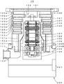
도 1은 본 발명의 실시 형태의 전체 구성도
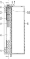
도 2는 베이스부 및 제어 장치 둘레의 종단면도
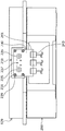
도 3은 도 2 중의 A-A 시시(矢視) 단면도
도 4는 베이스부를 받침부를 중심으로 하여 봤을 때의 정면도
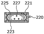
도 5는 가로로 긴 구조의 하메틱 커넥터의 이면도
도 6은 기판을 베이스부의 외측에서 봤을 때의 모습을 도시한 도면
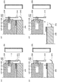
도 7은 보수 작업을 행할 때의 순서를 도시한 도면1 is an overall configuration diagram of an embodiment of the present invention
2 is a longitudinal sectional view around the base and the control device;
FIG. 3 is a cross-sectional view taken along AA in FIG. 2. FIG.
4 is a front view when viewed from the base portion of the base portion as a center;
5 is a rear view of a harmatic connector having a horizontally long structure;
6 is a view showing a state when the substrate is viewed from the outside of the base portion;
7 is a diagram illustrating a procedure when performing maintenance work.
이하, 본 발명의 실시 형태에 대해 설명한다. 본 발명의 실시 형태의 구성도를 도 1에 도시한다.EMBODIMENT OF THE INVENTION Hereinafter, embodiment of this invention is described. The structural diagram of embodiment of this invention is shown in FIG.
도 1에 있어서, 터보 분자 펌프(10)는, 펌프 본체(100)와 제어 장치(200)가 일체화되어 있다.In FIG. 1, the pump
펌프 본체(100)의 원통 형상의 외통(127)의 상단에는 흡기구(101)가 형성되어 있다. 외통(127)의 내방에는, 가스를 흡인 배기하기 위한 터빈 블레이드에 의한 복수의 회전 날개(102a, 102b, 102c···)를 둘레부에 방사 형상으로 또한 다단으로 형성한 회전체(103)를 구비한다.The
이 회전체(103)의 중심에는 로터축(113)이 부착되어 있고, 이 로터축(113)은, 예를 들어, 이른바 5축 제어의 자기베어링에 의해 공중에 부상 지지되고 또한 위치 제어되어 있다.The
상측 경방향 전자석(104)은, 4개의 전자석이, 로터축(113)의 경방향의 좌표축이며 서로 직교하는 X축과 Y축에 쌍을 이루어서 배치되어 있다. 이 상측 경방향 전자석(104)에 근접하고 또한 대응되어 4개의 전자석으로 이루어지는 상측 경방향 센서(107)가 구비되어 있다. 이 상측 경방향 센서(107)는 회전체(103)의 경방향 변위를 검출하고, 제어 장치(200)에 보내도록 구성되어 있다.In the upper
제어 장치(200)에 있어서는, 상측 경방향 센서(107)가 검출한 변위 신호에 의거하여, PID 조절 기능을 갖는 보상 회로를 통해 상측 경방향 전자석(104)의 여자를 제어하여, 로터축(113)의 상측의 경방향 위치를 조정한다.In the
로터축(113)은, 고투자율재(철 등) 등에 의해 형성되고, 상측 경방향 전자석(104)의 자력에 의해 흡인되도록 되어 있다. 이러한 조정은, X축 방향과 Y축 방향으로 각각 독립하여 행해진다.The
또, 하측 경방향 전자석(105) 및 하측 경방향 센서(108)가, 상측 경방향 전자석(104) 및 상측 경방향 센서(107)와 동일하게 배치되고, 로터축(113)의 하측의 경방향 위치를 상측의 경방향 위치와 동일하게 조정하고 있다.In addition, the lower
또한, 축 방향 전자석(106A, 106B)이, 로터축(113)의 하부에 구비한 원판 형상의 금속 디스크(111)를 상하에 끼워서 배치되어 있다. 금속 디스크(111)는, 철 등의 고투자율재로 구성되어 있다. 로터축(113)의 축 방향 변위를 검출하기 위해서 축 방향 센서(109)가 구비되고, 그 축 방향 변위 신호가 제어 장치(200)에 보내지도록 구성되어 있다.In addition, the axial electromagnets 106A and 106B are disposed with the disk-shaped metal disks 111 provided on the lower portion of the
그리고, 축 방향 전자석(106A, 106B)은, 이 축 방향 변위 신호에 의거하여 제어 장치(200)의 PID 조절 기능을 갖는 보상 회로를 통해 여자 제어되도록 되어 있다. 축 방향 전자석(106A)과 축 방향 전자석(106B)은, 자력에 의해 금속 디스크(111)를 각각 상방과 하방으로 흡인한다.The axial electromagnets 106A and 106B are configured to be excited by a compensation circuit having a PID adjustment function of the
이와 같이, 제어 장치(200)는, 이 축 방향 전자석(106A, 106B)이 금속 디스크(111)에 미치는 자력을 적당하게 조절하고, 로터축(113)을 축 방향으로 자기 부상시켜, 공간에 비접촉으로 유지하도록 되어 있다.Thus, the
모터(121)는, 로터축(113)을 둘러싸도록 둘레 형상으로 배치된 복수의 자극을 구비하고 있다. 각 자극은, 로터축(113)과의 사이에 작용하는 전자력을 통해 로터축(113)을 회전 구동하도록, 제어 장치(200)에 의해서 제어되고 있다.The motor 121 has a plurality of magnetic poles arranged in a circumferential shape so as to surround the
회전 날개(102a, 102b, 102c···)와 근소한 공극을 두고 복수 매의 고정 날개(123a, 123b, 123c···)가 배치되어 있다. 회전 날개(102a, 102b, 102c···)는, 각각 배기 가스의 분자를 충돌에 의해 하측 방향으로 이송하기 때문에, 로터축(113)의 축선에 수직인 평면으로부터 소정의 각도만큼 경사져 형성되어 있다.A plurality of stationary vanes 123a, 123b, 123c ... are disposed with the rotary vanes 102a, 102b, 102c ... and a slight gap. The rotary vanes 102a, 102b, and 102c are each formed to be inclined by a predetermined angle from a plane perpendicular to the axis of the
또, 고정 날개(123)도, 동일하게 로터축(113)의 축선에 수직인 평면으로부터 소정의 각도만큼 경사져 형성되고, 또한 외통(127)의 내방을 향해서 회전 날개(102)의 단과 서로 엇갈리게 배치되어 있다.Similarly, the fixed
그리고, 고정 날개(123)의 일단은, 복수 단이 쌓인 고정 날개 스페이서(125a, 125b, 125c···)의 사이에 끼워 넣어진 상태로 지지되어 있다.One end of the fixed
고정 날개 스페이서(125)는 링 형상의 부재이며, 예를 들어 알루미늄, 철, 스테인리스, 구리 등의 금속, 또는 이들 금속을 성분으로서 포함하는 합금 등의 금속에 의해서 구성되어 있다.The fixed
고정 날개 스페이서(125)의 외주에는, 근소한 공극을 두고 외통(127)이 고정되어 있다. 외통(127)의 바닥부에는 베이스부(129)가 배치되고, 고정 날개 스페이서(125)의 하부와 베이스부(129) 사이에는 나사 달린 스페이서(131)가 배치되어 있다. 그리고, 베이스부(129) 중의 나사 달린 스페이서(131)의 하부에는 배기구(133)가 형성되고, 외부에 연통되어 있다.The
나사 달린 스페이서(131)는, 알루미늄, 구리, 스테인리스, 철, 또는 이들 금속을 성분으로 하는 합금 등의 금속에 의해서 구성된 원통 형상의 부재이며, 그 내주면에 나선 형상의 나사 홈(131a)이 복수 줄 새겨져 있다.The threaded
나사 홈(131a)의 나선의 방향은, 회전체(103)의 회전 방향으로 배기 가스의 분자가 이동했을 때에, 이 분자가 배기구(133)쪽으로 이송되는 방향이다.The spiral direction of the screw groove 131a is a direction in which the molecules are transferred toward the exhaust port 133 when the molecules of the exhaust gas move in the rotational direction of the
회전체(103)의 회전 날개(102a, 102b, 102c···)에 이어지는 최하부에는 회전 날개(102d)가 수하(垂下)되어 있다. 이 회전 날개(102d)의 외주면은, 원통 형상이고, 또한 나사 달린 스페이서(131)의 내주면을 향해 돌출되어 있으며, 이 나사 달린 스페이서(131)의 내주면과 소정의 간극을 두고 근접되어 있다.The rotary blade 102d is drooping in the lowermost part which follows the rotary blades 102a, 102b, 102c ... of the
베이스부(129)는, 터보 분자 펌프(10)의 기저부를 구성하는 원반 형상의 부재이며, 일반적으로는 철, 알루미늄, 스테인리스 등의 금속에 의해서 구성되어 있다.The
베이스부(129)는 터보 분자 펌프(10)를 물리적으로 유지함과 더불어, 열의 전도로의 기능도 겸비하고 있으므로, 철, 알루미늄이나 구리 등의 강성이 있고, 열전도율도 높은 금속이 사용되는 것이 바람직하다.Since the
이러한 구성에 있어서, 회전 날개(102)가 모터(121)에 의해 구동되어 로터축(113)과 더불어 회전하면, 회전 날개(102)와 고정 날개(123)의 작용에 의해, 흡기구(101)를 통해서 챔버로부터의 배기 가스가 흡기된다.In such a configuration, when the
흡기구(101)로부터 흡기된 배기 가스는, 회전 날개(102)와 고정 날개(123) 사이를 통과하여, 베이스부(129)로 이송된다. 이때, 배기 가스가 회전 날개(102)에 접촉 또는 충돌할 때에 발생하는 마찰열이나, 모터(121)에서 발생한 열의 전도나 복사 등에 의해, 회전 날개(102)의 온도는 상승하나, 이 열은, 복사 또는 배기 가스의 기체 분자 등에 의한 전도에 의해 고정 날개(123)측에 전달된다.The exhaust gas taken in from the
고정 날개 스페이서(125)는, 외주부에서 서로 접합되어 있고, 고정 날개(123)가 회전 날개(102)로부터 수취한 열이나 배기 가스가 고정 날개(123)에 접촉 또는 충돌할 때에 발생하는 마찰열 등을 외통(127)이나 나사 달린 스페이서(131)로 전달한다. The fixed
나사 달린 스페이서(131)에 이송되어 온 배기 가스는, 나사 홈(131a)으로 안내되면서 배기구(133)로 보내진다.The exhaust gas transferred to the threaded
다음으로, 펌프 본체(100)와 제어 장치(200) 사이에서 제어 케이블이나 전원 케이블을 접속하는 단자 둘레의 구조에 대해 설명한다.Next, the structure around the terminal which connects a control cable or a power cable between the pump
도 2에는 베이스부 및 제어 장치 둘레의 단면도를 도시한다. 또, 도 3에는 도 2에 있어서의 A-A 시시 단면도를 도시한다. 도 2 및 도 3에 있어서, 베이스부(129)의 중앙에는 원기둥 형상의 바닥부 공간(201)이 형성되어 있다. 그리고, 이 바닥부 공간(201)으로부터 베이스부(129)의 측부로 통하는 연통 구멍(203)이 1개소 형성되어 있다.2 shows a sectional view around the base and the control device. 3 is a sectional view taken along the line A-A in FIG. 2. 2 and 3, a cylindrical
연통 구멍(203)은 바닥부 공간(201)측이 원형 구멍(203A)으로 되어 있어 좁고, 한편, 이 원형 구멍(230A)에 이어지는 외주측이 가로로 긴 구멍(203B)이며, 이 가로로 긴 구멍(203B)은 좌우 반월형의 장방 형상으로 형성되어 있다. 도 4에는 베이스부를 받침부를 중심으로 하여 외측에서 봤을 때의 정면도를 도시한다. 도 4에 있어서, 원형 구멍(203A)은 가로로 긴 구멍(203B)을 앞쪽으로 해서 안쪽에 보이고 있다. The
연통 구멍(203)은 도 3에 도시한 대로 원형 구멍(203A)과 가로로 긴 구멍(203B)이 각각 단면을 경방향을 향해서 일정하게 한 상태로 도중에 단차를 설치하여 접속되어 있다. 그러나, 연통 구멍(203)은 가로로 긴 구멍(203B)으로부터 원형 구멍(203A)을 향해 연속하여 점차 단면이 오므라들도록 형성되어도 된다. 연통 구멍(203)의 외측 단부에는 도 5에 도시한 가로로 긴 구조의 하메틱 커넥터(220)가 부착 가능하도록 주위에 볼트 구멍(209)을 갖는 받침부(210)가 형성되어 있다.As shown in FIG. 3, the
하메틱 커넥터(220)는 가로로 긴 구조이며, 세로 방향을 1로 했을 때에 가로 방향이 1.5배 이상, 보다 바람직하게는 2배 이상이 되는 것이 바람직하다. 이 받침부(210)의 연통 구멍(203)의 주위에는 좌우 반월형의 장방 형상의 오목부(211)가 새겨져 있다.The
도 5에 도시한 하메틱 커넥터(220)는 커넥터의 이면을 도시하고 있고, 이 하메틱 커넥터(220)는 네 모서리에 볼트 구멍(221)을 갖고 있다. 볼트 구멍(221)의 내측에는 받침부(210)의 오목부(211)에 대해서 매설되는 좌우 반월형의 장방 형상의 O링(223)이 구비되어 있다. O링(223)의 내측에는 세경(細徑)핀(224)이 통과하는 소경 구멍(225)이, 태경(太徑)핀(226)이 통과하는 3개의 대경 구멍(227)의 좌우에 각각 복수 개씩 배치되어 있다.The
도 2, 도 5에 도시한 바와 같이, 하메틱 커넥터(220)의 소경 구멍(225)을 통과한 세경핀(224)과 대경 구멍(227)을 통과한 태경핀(226)은 그 선단이 각각 도 3, 도 6에 도시한 기판(230)의 소경 구멍(235)과 대경 구멍(237)에 대해서 통과한다. 하메틱 커넥터(220)의 소경 구멍(225)의 내측과 대경 구멍(237)의 내측은 모두 진공 시일되어 있다. 도 6에는 기판(230)을 베이스부(129)의 외측에서 봤을 때의 모습을 도시한다. 도 6에 도시한 바와 같이 기판(230)의 네 모서리에는 볼트 구멍(231)이 배치되어 있다.As shown in FIGS. 2 and 5, the tip of the
도 5로부터 알 수 있듯이, 하메틱 커넥터(220)의 핀의 배열은, 펌프 본체(100)의 둘레 방향의 열수가 축 방향의 열수보다 많아지도록 배치되어 있다.As can be seen from FIG. 5, the arrangement of the pins of the
하메틱 커넥터(220)와 기판(230)은 받침부(210)에 대해서, 볼트 구멍(209), 볼트 구멍(221), 볼트 구멍(231)을 통해 볼트(239)로 나사 고정되도록 되어 있다. 기판(230)은 도시 생략하나 두께 방향으로 다층의 배선 패턴이 형성되어 있고, 기판(230)의 하단에는 단자(241)가 배치되어 있다. 배선 패턴은 전기적으로 일단이 세경핀(224)과 태경핀(226)의 각각의 핀에 대해서 접속되고, 타단이 단자(241)에 대해서 접속되어 있다.The
이 단자(241)로부터는 제2 전기적 케이블에 상당하는 하니스(243)에 의해 제어 장치(200) 내에 케이블이 넣어져 있다.From this terminal 241, the cable is inserted in the
다음으로, 본 발명의 실시 형태의 작용을 설명한다.Next, the effect | action of embodiment of this invention is demonstrated.
종래에, 하메틱 커넥터라고 하면 원형인 것이 사용되어 오고 있다. 그러나, 하메틱 커넥터가 원형인 경우에는 케이블이 집중하여 부피가 커지기 때문에 펌프 본체(100)의 축 방향의 높이가 높아지지 않을 수 없었다. 본 발명의 실시 형태에서는, 도 5에 도시한 바와 같이 핀의 배열이 펌프 본체의 둘레 방향의 열수가 축 방향의 열수보다 많아지는 가로로 긴 구조의 하메틱 커넥터(220)를 채용함으로써, 케이블을 수평 방향으로 분산할 수 있기 때문에 펌프 본체(100)의 축 방향의 높이를 낮출 수 있다.Conventionally, a circular one has been used as a hermetic connector. However, when the harmatic connector is circular, the height of the
또, 기판(230)을 이용하여 기판 내부에 형성된 다층의 배선 패턴으로 세경핀(224)과 태경핀(226)의 각각의 핀과 단자(241) 사이를 접속했으므로, 종래와 같이, 하니스로 걸쳐진 경우에 비해, 펌프 본체(100)의 경방향으로 케이블의 부피가 커져 부풀어 오르는 일이 없다. 이로 인해, 펌프 본체(100)의 경방향으로도 작게 구성할 수 있다.In addition, since the
도 2에 있어서, 전기적 케이블에 상당하는 케이블(261)의 우단은 세경핀(224)의 좌단과 태경핀(226)의 좌단에 대해서 납땜된다. 이 납땜 작업을 행하는 경우, 작업을 용이하게 하기 위해 하메틱 커넥터(220)를 베이스부(129)의 외측에 5~10센치 정도 꺼낸 형태로 행한다. 그리고, 납땜 작업의 완료 후에는, 하메틱 커넥터(220)를 받침부(210)에까지 밀어넣어 받침부(210)와 맞닿게 할 필요가 있다.In Fig. 2, the right end of the
그러나, 케이블(261)의 개수는 많고, 종래에는 전원선용의 허용 전류가 큰 굵은 케이블과 허용 전류가 작은 제어용이나 신호용의 가는 케이블이 원형의 하메틱 커넥터에서 집중하여 혼재되어 있고, 단단해서 구부리기 어려웠다. 이로 인해, 케이블을 묶어 연통 구멍(203) 내에 수납하는 것은 어려운 작업이었다.However, the number of
그래서, 본 실시 형태에서는, 하메틱 커넥터(220)와 기판(230)은, 도 5와 도 6에 도시한 바와 같이, 내측에 허용 전류가 큰 굵은 핀을 배치하고, 그 굵은 핀의 주위에 허용 전류가 작은 핀을 배치했다. 이것은 굵은 케이블은 가는 케이블에 비해 단단해서 구부리기 어렵기 때문이다.Therefore, in this embodiment, as shown in FIG. 5 and FIG. 6, the
단단해서 구부리기 어려운 케이블을 중앙에 모음으로써 케이블을 묶었을 때에 비틀기 쉽게 할 수 있다. 이로 인해, 하메틱 커넥터(220)를 묶어 1회전반 정도 비틀어, 케이블의 길이를 짧게 하고 나서 연통 구멍(203) 내에 대해 용이하게 수납할 수 있게 되었다.By stiffening cables that are hard to bend in the center, they can be easily twisted when bundled. For this reason, the
또, 기판(230)에는 두께 방향으로 다층의 배선 패턴이 형성됨으로써, 핀의 개수는 많은 한편으로 핀들의 간격은 좁힐 수 있다.In addition, since a plurality of wiring patterns are formed on the
다음으로, 본 실시 형태에서는, 상술한 대로 하메틱 커넥터(220)를 베이스부(129)의 옆에 배치함으로써, 보수 작업을 용이하게 행할 수 있게 되었다. 이 사이의 사정을 도 7의 보수 작업을 행할 때의 순서에 의거하여 설명한다.Next, in the present embodiment, the repair work can be easily performed by disposing the
우선, 보수 작업을 행할 때에는 도 7(a)에 도시한 바와 같이, 베이스부(129) 및 제어 장치(200)의 측부로부터 벽부 커버(251)를 떼어 낸다. 도 7(b)에서는 하니스(243)를 단자(241)로부터 떼어 낸다. 다음으로, 도 7(c)에서는 도시 생략한 베이스부(129) 및 제어 장치(200) 사이를 체결하고 있던 볼트를 분리하고, 제어 장치(200)의 하우징을 수십 밀리 정도 내린다. 다음으로 도 7(d)에 도시한 바와 같이, 제어 장치(200)의 하우징을 펌프의 경방향으로 꺼낸다.First, when performing the maintenance work, as shown in Fig. 7A, the
이것에 의해, 진공 펌프의 축 방향으로는 충분한 빈 공간이 없어도 용이하게 펌프 본체(100)와 제어 장치(200)의 착탈을 행할 수 있다. 이 경우에는, 펌프 본체(100)를 도시 생략한 챔버에 부착한 상태여도 제어 장치(200)의 보수 작업을 용이하게 행할 수 있다. 진공 펌프의 측부에 단자가 배치되어 있으므로 벽부 커버(251)를 떼어 냄으로써 보기 쉽고, 하니스(243)의 단자(241)로의 착탈도 용이하다.Thereby, the pump
또한, 본 발명의 실시 형태 및 각 변형예는, 필요에 따라서 조합하는 구성으로 해도 된다. 또, 본 발명은, 본 발명의 정신을 일탈하지 않는 한 여러 가지의 개변을 이룰 수 있고, 그리고, 본 발명이 당해 개변된 것에도 이르는 것은 당연하다.In addition, you may make it the structure of embodiment of this invention and each modified example combining as needed. Moreover, this invention can make various changes, unless it deviates from the mind of this invention, and it is natural that this invention also reaches the said modified.
10: 터보 분자 펌프
100: 펌프 본체
129: 베이스부
200: 제어 장치
201: 바닥부 공간
203: 연통 구멍
203A: 원형 구멍
203B: 가로로 긴 구멍
220: 하메틱 커넥터
224, 226: 핀
230: 기판
225, 235: 소경 구멍
227, 237: 대경 구멍
241: 단자
243: 하니스
261: 케이블10: turbomolecular pump 100: pump body
129: base portion 200: control device
201: bottom space 203: communication hole
203A:
220:
230:
227, 237: large diameter hole 241: terminal
243: harness 261: cable
Claims (8)
상기 펌프 본체의 둘레 방향으로 가로로 길어지도록, 상기 커넥터의 축 방향의 치수보다 상기 커넥터의 가로 방향의 치수가 긴 것을 특징으로 하는 진공 펌프.A connector disposed on the side of the base portion of the pump body, the connector having a plurality of pins connected to a plurality of electrical cables leading into the pump body;
And the horizontal dimension of the connector is longer than the axial dimension of the connector so as to extend horizontally in the circumferential direction of the pump body.
상기 커넥터의 상기 복수의 핀의 배열은, 상기 펌프 본체의 둘레 방향의 열수가 축 방향의 열수보다 많은 것을 특징으로 하는 진공 펌프.The method according to claim 1,
The arrangement of the plurality of pins of the connector is characterized in that the number of hot water in the circumferential direction of the pump body is larger than the number of hot water in the axial direction.
상기 복수의 핀 중, 상기 커넥터의 중앙 부분에는 지름이 굵은 핀이 배치되고,
당해 지름이 굵은 핀의 주위에 지름이 가는 핀이 배치된 것을 특징으로 하는 진공 펌프.The method according to claim 1 or 2,
Among the plurality of pins, a pin having a large diameter is disposed at a central portion of the connector,
A vacuum pump, wherein a thin pin is disposed around the pin with the diameter.
상기 지름이 굵은 핀의 상기 펌프 본체의 내부측의 단부에는, 상기 복수의 전기적 케이블 중, 지름이 굵은 전기적 케이블이 접속되어 있는 것을 특징으로 하는 진공 펌프.The method according to claim 3,
A thick electric cable is connected to an end portion of the pump main body of the thick pin, wherein a thick electric cable is connected among the plurality of electric cables.
상기 베이스부에 대해, 상기 펌프 본체를 제어하는 제어 장치를 착탈 가능하게 구비하고,
상기 복수의 핀의 대기측의 단부에는 전기적 접속용의 기판이 고착되며,
당해 기판에는 단자가 구비되고, 당해 단자에 접속된 제2 전기적 케이블을 통해 상기 제어 장치와 전기적으로 접속된 것을 특징으로 하는 진공 펌프.The method according to any one of claims 1 to 4,
The base unit is provided with a detachable control device for controlling the pump body,
The substrate for electrical connection is fixed to the air end part of the said several pin,
The said board | substrate is equipped with the terminal, The vacuum pump characterized by the electrically connected with the said control apparatus via the 2nd electrical cable connected to the said terminal.
상기 기판에 있어서의 상기 복수의 핀과 상기 단자 사이는 다층 구조의 배선 패턴에 의해 전기적으로 접속된 것을 특징으로 하는 진공 펌프.The method according to claim 5,
A vacuum pump, wherein the plurality of pins and the terminals of the substrate are electrically connected by a wiring pattern of a multilayer structure.
Applications Claiming Priority (3)
| Application Number | Priority Date | Filing Date | Title |
|---|---|---|---|
| JP2016256649A JP6912196B2 (en) | 2016-12-28 | 2016-12-28 | Vacuum pumps and connectors and control devices applied to the vacuum pumps |
| JPJP-P-2016-256649 | 2016-12-28 | ||
| PCT/JP2017/044246 WO2018123522A1 (en) | 2016-12-28 | 2017-12-08 | Vacuum pump and connector and control device applied to vacuum pump |
Publications (2)
| Publication Number | Publication Date |
|---|---|
| KR20190100911A true KR20190100911A (en) | 2019-08-29 |
| KR102450929B1 KR102450929B1 (en) | 2022-10-05 |
Family
ID=62710511
Family Applications (1)
| Application Number | Title | Priority Date | Filing Date |
|---|---|---|---|
| KR1020197014437A KR102450929B1 (en) | 2016-12-28 | 2017-12-08 | A vacuum pump, a connector applied to the vacuum pump, and a control device |
Country Status (6)
| Country | Link |
|---|---|
| US (1) | US11081845B2 (en) |
| EP (1) | EP3564534A4 (en) |
| JP (1) | JP6912196B2 (en) |
| KR (1) | KR102450929B1 (en) |
| CN (1) | CN109996965B (en) |
| WO (1) | WO2018123522A1 (en) |
Families Citing this family (1)
| Publication number | Priority date | Publication date | Assignee | Title |
|---|---|---|---|---|
| JP7124787B2 (en) | 2019-04-17 | 2022-08-24 | 株式会社島津製作所 | Power supply integrated vacuum pump |
Citations (5)
| Publication number | Priority date | Publication date | Assignee | Title |
|---|---|---|---|---|
| US5499935A (en) * | 1993-12-30 | 1996-03-19 | At&T Corp. | RF shielded I/O connector |
| JPH11173293A (en) | 1997-12-10 | 1999-06-29 | Ebara Corp | Turbo-molecular pump device |
| JP2006250033A (en) * | 2005-03-10 | 2006-09-21 | Shimadzu Corp | Turbo molecular pump |
| US20060281352A1 (en) * | 2005-06-09 | 2006-12-14 | Boc Edward Japan Limited | Terminal structure and vacuum pump |
| US20150237712A1 (en) * | 2012-11-29 | 2015-08-20 | Murata Manufacturing Co., Ltd. | Radio frequency module |
Family Cites Families (14)
| Publication number | Priority date | Publication date | Assignee | Title |
|---|---|---|---|---|
| US4906211A (en) * | 1987-01-30 | 1990-03-06 | Wyle Laboratories | Connector for aircraft-to-ground maintenance electrical connection |
| DE4438812A1 (en) * | 1994-10-31 | 1996-05-02 | Leybold Ag | Friction vacuum pump with cooling |
| JP2002021851A (en) * | 2000-07-04 | 2002-01-23 | Koyo Seiko Co Ltd | Magnetic bearing control device |
| US6793466B2 (en) * | 2000-10-03 | 2004-09-21 | Ebara Corporation | Vacuum pump |
| JP2003018797A (en) * | 2001-06-29 | 2003-01-17 | Teikoku Electric Mfg Co Ltd | Operation monitor for canned motor |
| EP1757825B1 (en) * | 2005-08-24 | 2010-09-29 | Mecos Traxler AG | Magnetic bearing device with an improved vacuum feedthrough |
| DE202007012070U1 (en) * | 2007-08-30 | 2009-01-08 | Oerlikon Leybold Vacuum Gmbh | Electric feedthrough of a vacuum pump |
| JP5257472B2 (en) * | 2010-04-02 | 2013-08-07 | 株式会社デンソー | Electronic equipment |
| JP5744044B2 (en) * | 2010-10-19 | 2015-07-01 | エドワーズ株式会社 | Vacuum pump |
| CN103228923B (en) * | 2010-10-19 | 2016-09-21 | 埃地沃兹日本有限公司 | Vacuum pump |
| JP6735526B2 (en) * | 2013-08-30 | 2020-08-05 | エドワーズ株式会社 | Vacuum pump |
| EP3029327B1 (en) * | 2014-12-02 | 2018-02-14 | Pfeiffer Vacuum Gmbh | System comprising vacuum device and functional unit |
| EP3088737B1 (en) * | 2015-04-30 | 2020-06-17 | Pfeiffer Vacuum Gmbh | Vacuum pump and method for producing a vacuum pump |
| JP6753759B2 (en) * | 2016-10-21 | 2020-09-09 | エドワーズ株式会社 | Vacuum pump and waterproof structure and control device applied to the vacuum pump |
-
2016
- 2016-12-28 JP JP2016256649A patent/JP6912196B2/en active Active
-
2017
- 2017-12-08 KR KR1020197014437A patent/KR102450929B1/en active IP Right Grant
- 2017-12-08 CN CN201780074550.XA patent/CN109996965B/en active Active
- 2017-12-08 WO PCT/JP2017/044246 patent/WO2018123522A1/en unknown
- 2017-12-08 EP EP17888020.9A patent/EP3564534A4/en active Pending
- 2017-12-08 US US16/469,794 patent/US11081845B2/en active Active
Patent Citations (5)
| Publication number | Priority date | Publication date | Assignee | Title |
|---|---|---|---|---|
| US5499935A (en) * | 1993-12-30 | 1996-03-19 | At&T Corp. | RF shielded I/O connector |
| JPH11173293A (en) | 1997-12-10 | 1999-06-29 | Ebara Corp | Turbo-molecular pump device |
| JP2006250033A (en) * | 2005-03-10 | 2006-09-21 | Shimadzu Corp | Turbo molecular pump |
| US20060281352A1 (en) * | 2005-06-09 | 2006-12-14 | Boc Edward Japan Limited | Terminal structure and vacuum pump |
| US20150237712A1 (en) * | 2012-11-29 | 2015-08-20 | Murata Manufacturing Co., Ltd. | Radio frequency module |
Also Published As
| Publication number | Publication date |
|---|---|
| WO2018123522A1 (en) | 2018-07-05 |
| US11081845B2 (en) | 2021-08-03 |
| JP6912196B2 (en) | 2021-08-04 |
| JP2018109371A (en) | 2018-07-12 |
| CN109996965B (en) | 2022-01-14 |
| CN109996965A (en) | 2019-07-09 |
| KR102450929B1 (en) | 2022-10-05 |
| US20200099179A1 (en) | 2020-03-26 |
| EP3564534A1 (en) | 2019-11-06 |
| EP3564534A4 (en) | 2020-08-12 |
Similar Documents
| Publication | Publication Date | Title |
|---|---|---|
| JP5778166B2 (en) | Vacuum pump | |
| JP5744044B2 (en) | Vacuum pump | |
| EP1732178A2 (en) | Terminal structure and vacuum pump | |
| KR102167207B1 (en) | Vacuum pump | |
| CN109790846B (en) | Vacuum pump and waterproof structure and control device applied to vacuum pump | |
| KR102450929B1 (en) | A vacuum pump, a connector applied to the vacuum pump, and a control device | |
| EP3951184A1 (en) | Vacuum pump and control device for vacuum pump | |
| JP2018145803A (en) | Control device, circuit board installed at said control device and vacuum pump applied with said control device |
Legal Events
| Date | Code | Title | Description |
|---|---|---|---|
| A201 | Request for examination | ||
| E902 | Notification of reason for refusal | ||
| E701 | Decision to grant or registration of patent right | ||
| GRNT | Written decision to grant |