KR20190061436A - Laminate Sheet with Modified Internal Surface and Pouch-Type Battery Comprising the Same - Google Patents
Laminate Sheet with Modified Internal Surface and Pouch-Type Battery Comprising the Same Download PDFInfo
- Publication number
- KR20190061436A KR20190061436A KR1020170159836A KR20170159836A KR20190061436A KR 20190061436 A KR20190061436 A KR 20190061436A KR 1020170159836 A KR1020170159836 A KR 1020170159836A KR 20170159836 A KR20170159836 A KR 20170159836A KR 20190061436 A KR20190061436 A KR 20190061436A
- Authority
- KR
- South Korea
- Prior art keywords
- laminate sheet
- sealant layer
- inner sealant
- secondary battery
- irregularities
- Prior art date
Links
- 239000010410 layer Substances 0.000 claims abstract description 61
- 239000000565 sealant Substances 0.000 claims abstract description 43
- 229910052751 metal Inorganic materials 0.000 claims abstract description 8
- 239000002184 metal Substances 0.000 claims abstract description 8
- 239000011247 coating layer Substances 0.000 claims abstract description 6
- 239000002952 polymeric resin Substances 0.000 claims abstract description 6
- 229920003002 synthetic resin Polymers 0.000 claims abstract description 6
- 238000007789 sealing Methods 0.000 claims description 37
- 239000003792 electrolyte Substances 0.000 claims description 23
- 230000004048 modification Effects 0.000 claims description 15
- 238000012986 modification Methods 0.000 claims description 15
- 238000000034 method Methods 0.000 claims description 14
- 230000008569 process Effects 0.000 claims description 10
- 239000000126 substance Substances 0.000 claims description 3
- 230000000903 blocking effect Effects 0.000 claims description 2
- 239000000463 material Substances 0.000 abstract 1
- 239000008151 electrolyte solution Substances 0.000 description 36
- 239000004743 Polypropylene Substances 0.000 description 13
- -1 polypropylene Polymers 0.000 description 13
- 229920001155 polypropylene Polymers 0.000 description 13
- 229920005989 resin Polymers 0.000 description 13
- 239000011347 resin Substances 0.000 description 13
- 230000000052 comparative effect Effects 0.000 description 5
- 239000011888 foil Substances 0.000 description 4
- 238000002347 injection Methods 0.000 description 4
- 239000007924 injection Substances 0.000 description 4
- 229910052782 aluminium Inorganic materials 0.000 description 3
- XAGFODPZIPBFFR-UHFFFAOYSA-N aluminium Chemical compound [Al] XAGFODPZIPBFFR-UHFFFAOYSA-N 0.000 description 3
- 238000005470 impregnation Methods 0.000 description 3
- 239000007788 liquid Substances 0.000 description 3
- 239000007787 solid Substances 0.000 description 3
- HBBGRARXTFLTSG-UHFFFAOYSA-N Lithium ion Chemical compound [Li+] HBBGRARXTFLTSG-UHFFFAOYSA-N 0.000 description 2
- 239000004840 adhesive resin Substances 0.000 description 2
- 229920006223 adhesive resin Polymers 0.000 description 2
- 229910001416 lithium ion Inorganic materials 0.000 description 2
- 238000004519 manufacturing process Methods 0.000 description 2
- 238000005259 measurement Methods 0.000 description 2
- 239000005022 packaging material Substances 0.000 description 2
- 239000000758 substrate Substances 0.000 description 2
- 230000003746 surface roughness Effects 0.000 description 2
- WHXSMMKQMYFTQS-UHFFFAOYSA-N Lithium Chemical compound [Li] WHXSMMKQMYFTQS-UHFFFAOYSA-N 0.000 description 1
- 239000004677 Nylon Substances 0.000 description 1
- 238000001994 activation Methods 0.000 description 1
- 239000012790 adhesive layer Substances 0.000 description 1
- 230000002457 bidirectional effect Effects 0.000 description 1
- 238000006243 chemical reaction Methods 0.000 description 1
- 230000003247 decreasing effect Effects 0.000 description 1
- 230000002542 deteriorative effect Effects 0.000 description 1
- 238000004146 energy storage Methods 0.000 description 1
- 229920006015 heat resistant resin Polymers 0.000 description 1
- 230000010354 integration Effects 0.000 description 1
- 229910052744 lithium Inorganic materials 0.000 description 1
- 238000000465 moulding Methods 0.000 description 1
- 229920001778 nylon Polymers 0.000 description 1
- 229920000642 polymer Polymers 0.000 description 1
- 238000003892 spreading Methods 0.000 description 1
- 230000007480 spreading Effects 0.000 description 1
- 238000004381 surface treatment Methods 0.000 description 1
Images

Classifications
-
- B—PERFORMING OPERATIONS; TRANSPORTING
- B32—LAYERED PRODUCTS
- B32B—LAYERED PRODUCTS, i.e. PRODUCTS BUILT-UP OF STRATA OF FLAT OR NON-FLAT, e.g. CELLULAR OR HONEYCOMB, FORM
- B32B3/00—Layered products comprising a layer with external or internal discontinuities or unevennesses, or a layer of non-planar shape; Layered products comprising a layer having particular features of form
- B32B3/26—Layered products comprising a layer with external or internal discontinuities or unevennesses, or a layer of non-planar shape; Layered products comprising a layer having particular features of form characterised by a particular shape of the outline of the cross-section of a continuous layer; characterised by a layer with cavities or internal voids ; characterised by an apertured layer
- B32B3/30—Layered products comprising a layer with external or internal discontinuities or unevennesses, or a layer of non-planar shape; Layered products comprising a layer having particular features of form characterised by a particular shape of the outline of the cross-section of a continuous layer; characterised by a layer with cavities or internal voids ; characterised by an apertured layer characterised by a layer formed with recesses or projections, e.g. hollows, grooves, protuberances, ribs
-
- B—PERFORMING OPERATIONS; TRANSPORTING
- B32—LAYERED PRODUCTS
- B32B—LAYERED PRODUCTS, i.e. PRODUCTS BUILT-UP OF STRATA OF FLAT OR NON-FLAT, e.g. CELLULAR OR HONEYCOMB, FORM
- B32B15/00—Layered products comprising a layer of metal
- B32B15/04—Layered products comprising a layer of metal comprising metal as the main or only constituent of a layer, which is next to another layer of the same or of a different material
- B32B15/08—Layered products comprising a layer of metal comprising metal as the main or only constituent of a layer, which is next to another layer of the same or of a different material of synthetic resin
-
- H01M2/0275—
-
- H01M2/0287—
-
- H01M2/1016—
-
- H—ELECTRICITY
- H01—ELECTRIC ELEMENTS
- H01M—PROCESSES OR MEANS, e.g. BATTERIES, FOR THE DIRECT CONVERSION OF CHEMICAL ENERGY INTO ELECTRICAL ENERGY
- H01M50/00—Constructional details or processes of manufacture of the non-active parts of electrochemical cells other than fuel cells, e.g. hybrid cells
- H01M50/10—Primary casings; Jackets or wrappings
- H01M50/102—Primary casings; Jackets or wrappings characterised by their shape or physical structure
- H01M50/105—Pouches or flexible bags
-
- H—ELECTRICITY
- H01—ELECTRIC ELEMENTS
- H01M—PROCESSES OR MEANS, e.g. BATTERIES, FOR THE DIRECT CONVERSION OF CHEMICAL ENERGY INTO ELECTRICAL ENERGY
- H01M50/00—Constructional details or processes of manufacture of the non-active parts of electrochemical cells other than fuel cells, e.g. hybrid cells
- H01M50/10—Primary casings; Jackets or wrappings
- H01M50/116—Primary casings; Jackets or wrappings characterised by the material
- H01M50/117—Inorganic material
- H01M50/119—Metals
-
- H—ELECTRICITY
- H01—ELECTRIC ELEMENTS
- H01M—PROCESSES OR MEANS, e.g. BATTERIES, FOR THE DIRECT CONVERSION OF CHEMICAL ENERGY INTO ELECTRICAL ENERGY
- H01M50/00—Constructional details or processes of manufacture of the non-active parts of electrochemical cells other than fuel cells, e.g. hybrid cells
- H01M50/10—Primary casings; Jackets or wrappings
- H01M50/116—Primary casings; Jackets or wrappings characterised by the material
- H01M50/121—Organic material
-
- H—ELECTRICITY
- H01—ELECTRIC ELEMENTS
- H01M—PROCESSES OR MEANS, e.g. BATTERIES, FOR THE DIRECT CONVERSION OF CHEMICAL ENERGY INTO ELECTRICAL ENERGY
- H01M50/00—Constructional details or processes of manufacture of the non-active parts of electrochemical cells other than fuel cells, e.g. hybrid cells
- H01M50/10—Primary casings; Jackets or wrappings
- H01M50/116—Primary casings; Jackets or wrappings characterised by the material
- H01M50/124—Primary casings; Jackets or wrappings characterised by the material having a layered structure
- H01M50/126—Primary casings; Jackets or wrappings characterised by the material having a layered structure comprising three or more layers
-
- H—ELECTRICITY
- H01—ELECTRIC ELEMENTS
- H01M—PROCESSES OR MEANS, e.g. BATTERIES, FOR THE DIRECT CONVERSION OF CHEMICAL ENERGY INTO ELECTRICAL ENERGY
- H01M50/00—Constructional details or processes of manufacture of the non-active parts of electrochemical cells other than fuel cells, e.g. hybrid cells
- H01M50/20—Mountings; Secondary casings or frames; Racks, modules or packs; Suspension devices; Shock absorbers; Transport or carrying devices; Holders
- H01M50/204—Racks, modules or packs for multiple batteries or multiple cells
- H01M50/207—Racks, modules or packs for multiple batteries or multiple cells characterised by their shape
- H01M50/211—Racks, modules or packs for multiple batteries or multiple cells characterised by their shape adapted for pouch cells
-
- B—PERFORMING OPERATIONS; TRANSPORTING
- B32—LAYERED PRODUCTS
- B32B—LAYERED PRODUCTS, i.e. PRODUCTS BUILT-UP OF STRATA OF FLAT OR NON-FLAT, e.g. CELLULAR OR HONEYCOMB, FORM
- B32B2307/00—Properties of the layers or laminate
- B32B2307/20—Properties of the layers or laminate having particular electrical or magnetic properties, e.g. piezoelectric
- B32B2307/206—Insulating
-
- Y—GENERAL TAGGING OF NEW TECHNOLOGICAL DEVELOPMENTS; GENERAL TAGGING OF CROSS-SECTIONAL TECHNOLOGIES SPANNING OVER SEVERAL SECTIONS OF THE IPC; TECHNICAL SUBJECTS COVERED BY FORMER USPC CROSS-REFERENCE ART COLLECTIONS [XRACs] AND DIGESTS
- Y02—TECHNOLOGIES OR APPLICATIONS FOR MITIGATION OR ADAPTATION AGAINST CLIMATE CHANGE
- Y02E—REDUCTION OF GREENHOUSE GAS [GHG] EMISSIONS, RELATED TO ENERGY GENERATION, TRANSMISSION OR DISTRIBUTION
- Y02E60/00—Enabling technologies; Technologies with a potential or indirect contribution to GHG emissions mitigation
- Y02E60/10—Energy storage using batteries
Landscapes
- Chemical & Material Sciences (AREA)
- Chemical Kinetics & Catalysis (AREA)
- Electrochemistry (AREA)
- General Chemical & Material Sciences (AREA)
- Inorganic Chemistry (AREA)
- Sealing Battery Cases Or Jackets (AREA)
Abstract
Description
본 발명은 내부 표면이 개질된 라미네이트 시트 및 이를 포함하는 파우치형 전지에 대한 것으로서, 구체적으로, 외부 피복층, 금속층 및 내부 실란트층으로 구성되는 전지케이스용 라미네이트 시트에서, 상기 내부 실란트층 표면에 요철이 형성되어 있으며, 상기 요철의 간격(Rsm)은 나노미터 단위의 크기이고, 요철의 높이(Rz)는 마이크로미터 단위의 크기인 라미네이트 시트 및 이를 포함하는 파우치형 전지에 대한 것이다.The present invention relates to a laminate sheet having an inner surface modified and a pouch type battery comprising the same, and more particularly, to a laminate sheet for a battery case comprising an outer coating layer, a metal layer and an inner sealant layer, , The spacing (R sm ) of the concavities and convexities is in the order of nanometers, and the height (R z ) of the concavities and convexities is in the order of micrometers, and a pouch-type battery comprising the laminate sheet.
이차전지는 모바일 기기의 에너지원으로서 많은 연구 및 개발이 진행되고 있다. 전지의 형상 면에서 얇은 두께로 휴대폰 등과 같은 제품들에 적용될 수 있는 각형 이차전지와 파우치형 이차전지에 대한 수요가 높고, 재료 면에서는 높은 에너지 밀도, 방전 전압, 출력 안정성 등의 장점을 가진 리튬이온 전지, 리튬이온 폴리머 전지 등과 같은 리튬 이차전지에 대한 수요가 높다.2. Description of the Related Art [0002] A secondary battery is being studied and developed as an energy source for mobile devices. In view of the shape of the battery, there is a demand for a prismatic secondary battery and a pouch type secondary battery that can be applied to products such as mobile phones with a small thickness, and lithium ions having a high energy density, discharge voltage, There is a high demand for lithium secondary batteries such as batteries, lithium ion polymer batteries and the like.
이차전지는 형상에 따라 원통형, 각형, 파우치형 등으로 구분할 수 있다. 그 중에서도 높은 집적도로 적층될 수 있고 중량당 에너지 밀도가 높으며 저렴하고 변형이 용이한 파우치형이 많은 관심을 모으고 있다.The secondary battery can be classified into a cylindrical shape, a square shape, and a pouch type according to the shape. Among them, a pouch type which can be stacked with a high degree of integration, has a high energy density per weight, and is inexpensive and easy to deform is attracting much attention.
상기 파우치형 이차전지는 양극 및 음극과 상기 양극 및 음극 사이에 개재되는 분리막으로 구성되는 전극조립체를 전지케이스 내부에 수납한 상태에서 전해액을 주입한 후 밀봉하여 제조되고 있다.The pouch type secondary battery is fabricated by injecting an electrolyte solution and sealing the electrode assembly in which the electrode assembly is composed of a positive electrode and a negative electrode and a separator interposed between the positive electrode and the negative electrode.
구체적으로, 전극조립체를 전지케이스 내부에 수납하고 일측 외주변을 제외한 나머지 외주변을 밀봉한 후, 상기 개방된 일측 외주변을 통해 전해액 주입 및 활성화 과정을 진행하고 전지케이스를 완전히 밀봉하게 된다.Specifically, after the electrode assembly is housed in the battery case and the outer periphery thereof is sealed except for one outer periphery, the electrolyte solution injection and activation process is performed through the opened outer periphery and the battery case is completely sealed.
상기 전해액 주입 과정에서 전지케이스의 내측면에 묻은 전해액이 잔존하는 바, 상기 잔존하는 전해액에 의해 전지케이스의 밀봉력이 저하되는 문제가 발생한다.The electrolyte solution remaining on the inner surface of the battery case remains in the electrolyte injection process, and the sealing force of the battery case is lowered due to the remaining electrolyte solution.
이에 대해, 특허문헌 1은 라미네이트 시트의 층간 강도를 확보하고, 전지케이스의 성형성을 향상시키기 위하여 내열성 수지층의 외측층, 금속박층 및 폴리프로필렌층의 내측층으로 구성되고, 상기 폴리프로필렌층의 내측면이 개질된 상태의 성형용 포장재를 개시하고 있다.On the other hand, Patent Document 1 is composed of the outer layer of the heat-resistant resin layer, the metal foil layer and the inner layer of the polypropylene layer in order to secure the interlaminar strength of the laminate sheet and to improve the moldability of the battery case, Discloses a molding packaging material with its inner surface modified.
또한, 특허문헌 2는 기재층, 알루미늄박, 화성 처리층, 접착층, 열접착성 수지층이 순서대로 적층된 전지용 포장재로서, 상기 열접착성 수지층의 표출면 중심선 표면 거칠기를 특정한 범위로 한정하고 있다.Patent Document 2 discloses a packaging material for a battery in which a substrate layer, an aluminum foil, a chemical conversion layer, an adhesive layer, and a thermally adhesive resin layer are laminated in order, wherein the surface roughness of the center line of the surface of the thermally adhesive resin layer is limited to a specific range have.
그러나, 전해액 주입 과정에서 전지케이스에 묻은 전해액이 전지케이스의 내측면에 잔존하지 않고 전극조립체 방향으로 흘러가도록 하기 위하여 전지케이스 내측면의 접촉각을 높이고 전해액과의 표면에너지를 높일 필요가 있는 바, 특허문헌 1 및 2는 이에 대해서는 전혀 인식하지 못하고 있다.However, it is necessary to increase the contact angle of the inner surface of the battery case and increase the surface energy with the electrolyte solution so that the electrolyte solution adhering to the battery case does not remain on the inner surface of the battery case during the electrolyte injection process and flows toward the electrode assembly. Documents 1 and 2 are not aware of this at all.
따라서, 파우치형 전지의 전지케이스로서 라미네이트 시트를 사용하는 경우, 전해액 주입 과정에서 전지케이스의 내측 실링부에 잔존하는 전해액으로 인하여 전지케이스의 밀봉력이 저하되는 것을 방지하기 위한 표면 처리 기술은 제시되지 않았다.Accordingly, when a laminate sheet is used as a battery case of a pouch-shaped battery, a surface treatment technique for preventing the sealing strength of the battery case from being lowered due to the electrolyte remaining in the inner sealing portion of the battery case during the electrolyte injection process is proposed I did.
본 발명은 상기와 같은 종래기술의 문제점을 해결하기 위한 것으로서, 외부 피복층, 금속층 및 내부 실란트층을 포함하는 라미네이트 시트에서, 내부 실란트층 표면에 전해액이 묻더라도 내부 실란트층의 표면에서 넓게 퍼지지 않고, 내부 실란트층과 접하는 면적을 최소화할 수 있으며, 전지케이스의 실링 예정부위에 전해액이 잔존함으로써, 파우치형 전지의 밀봉력이 저하되는 것을 방지할 수 있는 기술을 제공하는 것을 목적으로 한다.It is an object of the present invention to provide a laminate sheet including an outer coating layer, a metal layer, and an inner sealant layer, which does not spread widely on the surface of the inner sealant layer even when an electrolyte is deposited on the surface of the inner sealant layer, And an object of the present invention is to provide a technique capable of minimizing an area in contact with the inner sealant layer and preventing the sealing ability of the pouch-shaped battery from deteriorating due to the presence of an electrolytic solution remaining in a portion to be sealed of the battery case.
이러한 목적을 달성하기 위한 본 발명에 따른 라미네이트 시트는,According to an aspect of the present invention, there is provided a laminate sheet comprising:
전기절연성의 고분자 수지를 포함하는 외부 피복층;An outer coating layer including an electrically insulating polymer resin;
외부 물질의 유입을 차단하기 위한 금속층; 및A metal layer for blocking the inflow of foreign substances; And
열융착성 고분자 수지를 포함하는 내부 실란트층;An inner sealant layer comprising a heat-sealable polymer resin;
을 포함하고,/ RTI >
상기 내부 실란트층은 표면에 요철이 형성되어 있으며, 상기 요철의 간격(Rsm)은 나노미터 단위의 크기이고, 요철의 높이(Rz)는 마이크로미터 단위의 크기로 이루어질 수 있다.The inner sealant layer and irregularities are formed on the surface, the distance between the irregularities (R sm) is the size of a nanometer unit, a height of irregularities (R z) may be made of a size of micrometers.
일반적으로, 파우치형 전지의 제조시 일측 실링부를 제외한 나머지 실링부를 밀봉하고, 개방된 상태인 상기 일측 실링부를 통해 전해액을 주액하는데, 전지케이스 내측면이 매끄러운 경우에는 전해액의 표면에너지가 낮기 때문에 전해액이 묻게 되면 넓게 퍼지면서 흘러내리지 않고 전지케이스의 내측면인 내부 실란트층에 잔존하게 된다.Generally, when manufacturing a pouch-shaped battery, the remaining sealing portions are sealed except for one sealing portion, and the electrolyte is poured through the one-side sealing portion in an opened state. When the inner surface of the battery case is smooth, the surface energy of the electrolyte is low. It spreads widely and remains on the inner sealant layer which is the inner surface of the battery case without flowing down.
이후, 상기 전해액이 잔존하는 전지케이스에 대해 실링을 하는 경우, 잔존하는 전해액에 의해 실링강도가 현저히 낮아지게 된다.Thereafter, when the battery case in which the electrolyte solution remains is sealed, the sealing strength is remarkably lowered by the remaining electrolyte solution.
그러나, 본원발명과 같이, 전해액이 전지케이스를 통과하는 면에 위치하는 내부 실란트층 표면에 요철을 형성하는 경우, 상기 내부 실란트층의 접촉각이 증가하기 때문에 내부 실란트층에 대한 전해액의 젖음성이 낮아진다.However, when unevenness is formed on the surface of the inner sealant layer positioned on the surface of the electrolyte solution passing through the battery case as in the present invention, the contact angle of the inner sealant layer is increased, so that the wettability of the electrolyte solution to the inner sealant layer is lowered.
또한, 상기 요철의 간격(Rsm)은 나노미터 단위의 크기이고, 요철의 높이(Rz)는 마이크로미터 단위의 크기로 형성되는 바, 상기 요철은 요철들 간의 간격 대비 상대적으로 높이가 큰 형태로 형성되고, 요철 각각은 가늘고 긴 구조로 이루어진다.In addition, the interval (R sm ) of the irregularities is in the order of nanometers, and the height (R z ) of the irregularities is in the order of micrometers. The irregularities have a relatively large height And each of the concavities and convexities has an elongated structure.
따라서, 상기 요철이 형성된 내부 실란트층을 흐르는 전해액 방울은 실란트층과의 표면에너지가 증가하여 구형에 가까운 형상이 되는 바, 전해액이 내부 실란트층의 표면에 넓게 퍼지지 않고 전극조립체 방향으로 흘러가기 때문에 전지케이스의 내측면에 잔존하는 전해액의 양을 줄일 수 있으며, 결과적으로, 상기 잔존하는 전해액에 의해 전지케이스의 밀봉력이 저하되는 것을 방지할 수 있다.Therefore, the electrolyte solution flowing through the inner sealant layer formed with the irregularities increases in surface energy with the sealant layer to become a shape close to the sphere, and the electrolyte flows toward the electrode assembly without spreading widely on the surface of the inner sealant layer, The amount of the electrolytic solution remaining on the inner surface of the case can be reduced. As a result, the sealing ability of the battery case can be prevented from being lowered by the remaining electrolytic solution.
하나의 구체적인 예에서, 상기 요철의 간격(Rsm)은 1㎚ 내지 100㎚일 수 있으며, 상세하게는 20㎚ 내지 100㎚일 수 있고, 더욱 상세하게는 40㎚ 내지 70㎚일 수 있다.In one specific example, the interval (R sm ) of the irregularities may be 1 nm to 100 nm, more specifically 20 nm to 100 nm, and more specifically, 40 nm to 70 nm.
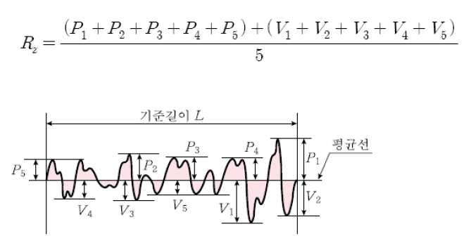
상기 요철의 간격(Rsm)은, 표면 거칠기를 측정한 거칠기 프로파일에서, 프로파일 곡선 요소 길이의 평균 간격을 의미하며, 하기와 같이, 측정 대상이 되는 기준길이(l)에 있는 각각의 길이(Xs)의 평균값으로 구할 수 있다.The interval (R sm ) of the concavities and convexities means the average interval of the lengths of the profile curve elements in the roughness profile in which the surface roughness is measured. The lengths (Xs ). ≪ / RTI >

상기 요철의 간격이 1㎚보다 작은 경우에는 상기 요철을 형성하기 위한 공정이 복잡하여 공정 효율성이 낮아질 수 있고, 100㎚보다 큰 경우에는 접촉각의 증가폭이 작아질 수 있으므로 바람직하지 않다.When the interval between the concavities and convexities is smaller than 1 nm, the process for forming the concavities and convexities is complicated and the process efficiency may be lowered. When the interval is larger than 100 nm, the increase of the contact angle may be decreased.
상기 요철의 높이(Rz)는 1㎛ 내지 100㎛일 수 있으며, 상세하게는 20㎛ 내지 100㎛일 수 있고, 더욱 상세하게는 20㎛ 내지 50㎛일 수 있다.The height (R z ) of the concavities and convexities may be 1 탆 to 100 탆, more specifically 20 탆 to 100 탆, and more specifically 20 탆 to 50 탆.
상기 요철의 높이(Rz)는 10점 평균거칠기라고도 표현하며, 거칠기 프로파일의 기준길이(L)에 대한 데이터에서 높은 피크 순으로 5개 값의 평균과 낮은 순으로 5개 값의 평균을 더한 값으로 구할 수 있다.The height (R z ) of the concavities and convexities is also referred to as a 10-point average roughness. The height (R z ) of the concavities and convexities is expressed by a 10-point average roughness .
상기 요철의 높이가 1㎛ 보다 작은 경우에는 요철의 길이가 짧기 때문에 가늘고 긴 형태의 요철을 형성하기 위한 목적을 달성하기 어렵고, 100㎛ 보다 큰 경우에는 길이가 긴 요철을 형성하기 위한 공정 대비 접촉각 증가의 효율성이 떨어지기 때문에 바람직하지 않다.When the height of the irregularities is less than 1 탆, the purpose of forming the irregularities of slender shape is difficult to achieve because the length of the irregularities is short. When the height of the irregularities is more than 100 탆, Which is not preferable.
접촉각이란, 액체가 고체면에 접촉할 때 액체 표면과 고체벽이 이루는 각도를 말하며, 접촉각이 90도 보다 클 때는 액체가 고체 표면을 적시는 젖음성이 낮아지고, 0도 내지 90도의 범위일 때는 젖음성이 높아진다.The contact angle refers to the angle formed by the liquid surface and the solid wall when the liquid contacts the solid surface. When the contact angle is greater than 90 degrees, the wettability of the liquid with respect to the solid surface is lowered. .
따라서, 상기 내부 실란트층의 접촉각이 클수록 전해액이 전지케이스 표면에 묻어나지 않게 된다.Therefore, the larger the contact angle of the inner sealant layer is, the less the electrolyte solution will remain on the battery case surface.
상기 라미네이트 시트는 가늘고 긴 형태의 요철이 표면에 형성되어 있기 때문에 전해액 방울이 거의 구형에 가까운 형태로 형성되고 상기 내부 실란트층의 접촉각이 매우 큰 값을 갖다. 예를 들어, 상기 내부 실란트층의 접촉각(contact angle)은 130도 내지 180도일 수 있고, 상기 요철의 간격 및 높이의 크기에 따라 상기 내부 실란트층의 접촉각은 상기의 범위 내에서 더 큰 각도를 갖는 값으로 형성될 수 있다.Since the laminate sheet has elongated irregularities formed on its surface, the droplets of the electrolyte are formed in a nearly spherical shape, and the contact angle of the inner sealant layer is very large. For example, the contact angle of the inner sealant layer may be between 130 and 180 degrees, and the contact angle of the inner sealant layer may be greater within the above range depending on the size of the gap and the height of the unevenness Lt; / RTI >
상기와 같이 라미네이트 시트의 내측면을 형성하는 내부 실란트층에 요철을 형성하는 방법은, 상기와 같은 크기의 요철의 간격 내지 요철의 높이를 갖도록 형성할 수 있다면 특별히 한정되지 않지만, 예를 들어, 상기 요철은 롤투롤(roll to roll) 공정 또는 스템프(stamp)를 이용한 나노임프린트(nano imprint) 공정에 의해 형성될 수 있고, 상기 롤투롤 공정에서 사용되는 롤러의 표면에는 나노미터 단위 크기의 간격으로 이격되어 있고, 마이크로미터 단위의 크기의 높이를 갖는 요철들이 형성되어 있다.The method of forming the concavo-convex in the inner sealant layer forming the inner side of the laminate sheet as described above is not particularly limited as long as it can be formed so as to have the interval of irregularities or the height of the concave and convex portions of the same size, The irregularities may be formed by a roll-to-roll process or a nano imprint process using a stamp, and the surface of the rollers used in the roll-to-roll process may be spaced apart by a nanometer- And irregularities having a height of a micrometer-unit size are formed.
본 발명은 상기의 라미네이트 시트를 포함하는 파우치형 이차전지를 제공하는 바, 상기의 라미네이트 시트에 전극조립체 수납부에 전극조립체를 위치시킨 후, 상기 전극조립체 수납부의 외주변 중 일측 외주변을 제외한 나머지 외주변을 실링하며, 상기 일측 외주변을 통해 전해액을 주입한다.The present invention provides a pouch-type secondary battery including the above-described laminate sheet, wherein after positioning the electrode assembly in the electrode assembly receiving portion in the laminate sheet, the outer periphery of the electrode assembly receiving portion, And the electrolyte is injected through the periphery of the one side.
상기 라미네이트 시트는 내부 실란트층의 표면에 요철이 형성되어 있기 때문에 낮은 전해액 젖음성(wetting)을 갖는 것을 특징으로 하는 바, 상기 전해액이 주입된 방향의 일측 외주변의 실링 강도가 향상되기 때문에, 밀봉력이 향상된 파우치형 이차전지를 제공할 수 있다.Since the laminate sheet has low electrolyte wettability due to the unevenness formed on the surface of the inner sealant layer, the sealing strength of the outer periphery of one side in the direction in which the electrolyte is injected is improved, This improved pouch type secondary battery can be provided.
하나의 구체적인 예에서, 상기 파우치형 이차전지는, 전지케이스의 내부 실란트층 표면 전체에 요철이 형성된 표면 개질부를 포함하는 구조로 이루어질 수 있다.In one specific example, the pouch-type secondary battery may have a structure including a surface modification portion in which unevenness is formed on the entire surface of the inner sealant layer of the battery case.
이와 같이 전지케이스의 내부 실란트층 표면 전체에 표면 개질부가 형성되는 경우에는, 전해액의 젖음성이 낮은 전지케이스를 사용하기 때문에 상대적으로 전극조립체 방향으로 전해액의 이동을 쉽게 유도할 수 있는 바, 전극조립체의 전해액 함침성을 향상시킬 수 있다.In the case where the surface modification portion is formed on the entire surface of the inner sealant layer of the battery case as described above, since the battery case having low wettability of the electrolyte solution is used, the movement of the electrolyte solution can be relatively easily induced toward the electrode assembly. The impregnability of the electrolyte solution can be improved.
다른 하나의 구체적인 예에서, 상기 파우치형 이차전지는, 전해액이 주입되는 방향에 위치하는 실링부의 내부 실란트층 표면에 요철이 형성된 표면 개질부를 포함하는 구조로 이루어질 수 있다.In another specific example, the pouch-type secondary battery may have a structure including a surface modification portion in which recesses and protrusions are formed on a surface of an inner sealant layer of a sealing portion located in a direction in which an electrolyte is injected.
이와 같이, 전해액이 주입되는 방향에 위치하는 실링부 부분에 표면 개질부가 형성되기 때문에, 전해액 주입시 상기 표면 개질부에 전해액이 묻어서 잔존하는 것을 방지할 수 있으므로, 전지케이스의 실링시 밀봉력이 저하되는 것을 방지할 수 있다.Since the surface modification portion is formed in the sealing portion located in the direction in which the electrolyte solution is injected, it is possible to prevent the electrolytic solution from remaining on the surface modification portion when the electrolyte solution is injected, Can be prevented.
상기와 같이, 표면 개질부는 라미네이트 시트의 내부 실란트층 표면 전체에 형성되거나, 또는 전해액이 주입되는 방향의 실링부에 형성될 수 있는 바, 상기 표면 개질부는 해당 부분에 전체적으로 형성될 수 있고, 또는 특정한 패턴을 갖는 형태로 이루어질 수 있다. 구체적으로, 상기 표면 개질부의 형태는 전지케이스에 대한 전해액의 함침성을 낮추어 전지케이스의 밀봉력이 감소하는 것을 방지할 수 있다면 특별히 한정되지 않지만, 예를 들어, 상기 표면 개질부는 복수의 직선형 구조 또는 복수의 원형 구조로 이루어질 수 있다.As described above, the surface modifying portion may be formed on the entire surface of the inner sealant layer of the laminate sheet, or may be formed on the sealing portion in the direction in which the electrolyte is injected. The surface modifying portion may be formed entirely in the portion, Pattern. ≪ / RTI > Specifically, the shape of the surface modification part is not particularly limited as long as the impregnation property of the electrolyte solution to the battery case is lowered to prevent the sealing ability of the battery case from being reduced. For example, the surface modification part may have a plurality of straight- And may be formed of a plurality of circular structures.
본 발명은 또한, 상기의 파우치형 이차전지를 단위셀로 포함하는 전지팩을 제공한다.The present invention also provides a battery pack including the pouch type secondary battery as a unit cell.
구체적으로, 상기 전지팩은 고온 안전성 및 긴 사이클 특성과 높은 레이트 특성 등이 요구되는 디바이스의 전원으로 사용될 수 있으며, 이러한 디바이스의 상세한 예로는, 모바일 전자기기(mobile device), 웨어러블 전자기기(wearable device), 전지적 모터에 의해 동력을 받아 움직이는 파워 툴(power tool); 전기자동차(Electric Vehicle, EV), 하이브리드 전기자동차(Hybrid Electric Vehicle, HEV), 플러그-인 하이브리드 전기자동차(Plug-in Hybrid Electric Vehicle, PHEV) 등을 포함하는 전기차; 전기 자전거(E-bike), 전기 스쿠터(E-scooter)를 포함하는 전기 이륜차; 전기 골프 카트(electric golf cart); 전력 저장 장치(Energy Storage System) 등을 들 수 있으나, 이에 한정되는 것은 아니다.Specifically, the battery pack may be used as a power source for devices requiring high-temperature safety, long cycle characteristics, and high rate characteristics. Examples of such devices include a mobile device, a wearable device A power tool powered by an electric motor; An electric vehicle including an electric vehicle (EV), a hybrid electric vehicle (HEV), a plug-in hybrid electric vehicle (PHEV), and the like; An electric motorcycle including an electric bike (E-bike) and an electric scooter (E-scooter); An electric golf cart; And an energy storage system, but the present invention is not limited thereto.
이들 디바이스의 구조 및 그것의 제작 방법은 당업계에 공지되어 있으므로, 본 명세서에서는 그에 대한 자세한 설명은 생략한다.The structure of these devices and their fabrication methods are well known in the art, and a detailed description thereof will be omitted herein.
이상에서 설명한 바와 같이, 본 발명에 따른 라미네이트 시트 및 이를 포함하는 파우치형 전지는, 라미네이트 시트를 구성하는 내부 실란트층 표면에 미세 요철이 형성되어 있으며, 상기 요철의 간격(Rsm)은 나노미터 단위의 크기이고, 요철의 높이(Rz)는 마이크로미터 단위의 크기로 이루어지는 바, 상기 내부 실란트층의 접촉각이 증가하고 전해액의 표면 에너지가 매우 높은 상태로 형성되기 때문에 전해액이 상기 내부 실란트층의 표면에 넓게 퍼지며 잔존하는 것을 방지할 수 있다.As described above, in the laminated sheet according to the present invention and the pouch-shaped battery including the same, fine irregularities are formed on the surface of the inner sealant layer constituting the laminate sheet, and the interval (R sm ) And the height (R z ) of the irregularities is in the order of micrometers. Since the contact angle of the inner sealant layer is increased and the surface energy of the electrolyte is formed to be very high, the surface of the inner sealant layer So that it can be prevented from remaining.
이와 같이, 상기 내부 실란트층의 표면에 잔존하는 전해액의 양을 줄일 수 있으므로, 이와 같은 라미네이트 시트를 사용하여 제조되는 파우치형 전지의 밀봉력을 향상시킬 수 있다.Since the amount of the electrolytic solution remaining on the surface of the inner sealant layer can be reduced, the sealing performance of the pouch-shaped battery manufactured using such a laminate sheet can be improved.
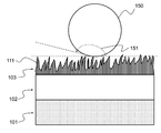
도 1은 하나의 실시예에 따른 라미네이트 시트의 수직 단면도이다.
도 2는 도 1의 라미네이트 시트에서 전해액의 접촉각을 나타내고 있다.
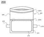
도 3은 전해액 주액 후 실링이 이루어지기 전의 파우치형 전지의 정면도이다.
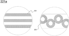
도 4는 도 3의 표면 개질부의 확대도이다.1 is a vertical cross-sectional view of a laminate sheet according to one embodiment.
Fig. 2 shows the contact angle of the electrolyte in the laminate sheet of Fig.
Fig. 3 is a front view of the pouch-shaped battery before sealing with electrolyte solution.
4 is an enlarged view of the surface modification portion of Fig.
이하 첨부된 도면을 참조하여 본 발명이 속하는 기술분야에서 통상의 지식을 가진 자가 본 발명을 쉽게 실시할 수 있는 실시예를 상세히 설명한다. 다만, 본 발명의 바람직한 실시예에 대한 동작 원리를 상세하게 설명함에 있어 관련된 공지 기능 또는 구성에 대한 구체적인 설명이 본 발명의 요지를 불필요하게 흐릴 수 있다고 판단되는 경우에는 그 상세한 설명을 생략한다.DETAILED DESCRIPTION OF THE PREFERRED EMBODIMENTS Hereinafter, embodiments of the present invention will be described in detail with reference to the accompanying drawings. However, the detailed description of known functions and configurations incorporated herein will be omitted when it may unnecessarily obscure the subject matter of the present invention.
또한, 도면 전체에 걸쳐 유사한 기능 및 작용을 하는 부분에 대해서는 동일한 도면 부호를 사용한다. 명세서 전체에서, 어떤 부분이 다른 부분과 연결되어 있다고 할 때, 이는 직접적으로 연결되어 있는 경우뿐만 아니라, 간접적으로 연결되어 있는 경우도 포함한다. 또한, 어떤 구성요소를 포함한다는 것은 특별히 반대되는 기재가 없는 한 다른 구성요소를 제외하는 것이 아니라, 다른 구성요소를 더 포함할 수 있는 것을 의미한다.The same reference numerals are used for portions having similar functions and functions throughout the drawings. Throughout the specification, when a part is connected to another part, it includes not only a direct connection but also an indirect connection. In addition, the inclusion of an element does not exclude other elements, but may include other elements, unless specifically stated otherwise.
본 발명을 도면에 따라 상세한 실시예와 같이 설명한다. The present invention will be described in detail with reference to the drawings.
도 1은 하나의 실시예에 따른 라미네이트 시트의 수직 단면도를 모식적으로 도시하고 있으며, 도 2는 도 1의 라미네이트 시트에서 전해액의 접촉각을 나타내고 있다.FIG. 1 schematically shows a vertical cross-sectional view of a laminate sheet according to one embodiment, and FIG. 2 shows the contact angle of the electrolyte in the laminate sheet of FIG.
도 1 및 도 2를 참조하면, 라미네이트 시트(100)는 외측으로부터 내측 방향으로 외부 피복층(101), 금속층(102) 및 내부 실란트층(103)이 순서대로 적층되어 있고, 내부 실란트층(103)의 표면에는 요철(111)이 형성되어 있다.1 and 2, an
내부 실란트층(103)의 표면에 위치하는 전해액 방울(150)은 거의 구형에 가까운 형태로 형성될 정도로 높은 표면에너지를 갖고 있으며, 내부 실란트층(103) 상에 위치하는 전해액 방울의 접촉각(151)은 90도를 훨씬 초과하는 값으로 형성되는 바, 130도 내지 180도의 범위로 형성될 수 있다.The
요철(111)의 간격(Rsm)은 1㎚ 내지 100㎚로 형성되고, 요철(111)의 높이(Rz)는 1㎛ 내지 100㎛로 형성된다.The interval R sm of the concavities and
도 3은 전해액 주액 후 실링이 이루어지기 전의 파우치형 전지의 외관을 도시하고 있으며, 도 4는 도 3의 표면 개질부의 부분 확대도이다.Fig. 3 shows the appearance of the pouch-type battery before sealing with electrolyte solution, and Fig. 4 is a partially enlarged view of the surface modification part of Fig.
도 3 및 도 4를 참조하면, 파우치형 전지(200)는 전지케이스(201)의 전극조립체 수납부(211)에 전극조립체(213)가 위치하고 있고, 전해액을 주입하기 위한 일측 외주변을 제외한 나머지 실링부는 밀봉된 상태이다. 전극조립체(213)는 전극 단자(212)가 서로 대향하는 방향으로 돌출된 양방향 전극조립체를 도시하고 있으나, 서로 동일한 방향으로 돌출된 일방향 전극조립체를 사용하는 것도 가능함은 물론이다.3 and 4, the pouch-shaped
파우치형 전지(200)의 개방된 외주변을 통해 전해액이 주입되는 바, 전극조립체 수납부(211)와 인접한 실링 예정부에는, 전지케이스용 라미네이트 시트의 내부 실란트층 표면에 표면 개질부(221b)가 형성되어 있고, 가스 포집을 위한 가스 포집부(225)의 외측 외주변에도 표면 개질부(221a)가 형성되어 있다. 따라서, 가스 포집부(225) 형성을 위한 밀봉부 형성시 높은 실링 강도를 확보할 수 있고, 또한, 가스 포집부(225)를 제거하기 전 전극조립체 수납부 외주변의 밀봉부 형성시에도 높은 실링 강도를 확보할 수 있다.The electrolyte solution is injected through the open periphery of the pouch-shaped
표면 개질부(221a) 및 표면 개질부(221b)의 평면상 형상은 서로 동일할 수 있고, 또는 서로 상이할 수 있는 바, 복수의 직선형 구조(222)가 형성되는 구조이거나, 또는 복수의 원형 구조(223)가 형성된 구조일 수 있다. 복수의 원형 구조(223)가 형성되는 경우에는, 밀봉 후 전해액이 누액되는 것을 방지해야 하는 바, 실링부의 길이 방향으로 미실링부가 형성되지 않고 연속적인 밀봉이 이루어질 수 있도록, 상기 원형 구조가 중첩적으로 형성되는 것이 바람직하다.The planar shapes of the
한편, 상기와 같이 실링 예정부에만 표면 개질부가 형성되는 파우치형 전지 이외에, 파우치형 전지의 내측 실란트층 전체에 표면 개질부가 형성될 수 있는 바, 이와 같은 경우, 표면 개질부가 형성된 부분에서 밀봉이 이루어지도록 위치 조정 등을 할 필요가 없으며, 전지케이스에 대한 전해액 함침성이 낮기 때문에, 상대적으로 전극조립체에 대한 전해액 함침성이 향상될 수 있는 장점이 있다.Meanwhile, in addition to the pouch-type battery in which the surface modifying part is formed only on the sealing part as described above, the surface modifying part may be formed on the entire inner sealant layer of the pouch type battery. In this case, It is not necessary to adjust the position of the electrode assembly so that the electrolyte solution impregnation property of the battery case is low. Therefore, the electrolyte solution impregnation property of the electrode assembly can be relatively improved.
이하, 실시예를 통해 본원 발명을 더욱 상술하지만, 하기 실시예는 본원 발명을 예시하기 위한 것이며, 본원 발명의 범주가 이들만으로 한정되는 것은 아니다.Hereinafter, the present invention will be described in further detail with reference to the following examples. However, the following examples are intended to illustrate the present invention, and the scope of the present invention is not limited thereto.
<실시예 1>≪ Example 1 >
70㎚의 간격으로 이격되고 20㎛의 높이를 갖는 요철이 형성된 롤러를 이용하여 폴리프로필렌 수지 표면을 개질하여 요철이 형성된 폴리프로필렌 수지를 제조하였다.The surface of the polypropylene resin was modified using a roller having a concavo-convex portion spaced at an interval of 70 nm and having a height of 20 mu m to produce a polypropylene resin having unevenness.
상기 요철의 간격(Rsm)은 70㎚이고, 요철의 높이(Rz)는 20㎛로 형성되었다.The interval (R sm ) of the concavities and convexities was 70 nm, and the height (R z ) of the concavities and convexities was 20 μm.
<비교예 1>≪ Comparative Example 1 &
개질된 폴리프로필렌 수지 표면에 형성된 요철의 간격(Rsm)이 200㎚이고, 요철의 높이(Rz)는 0.5㎛로 형성된 점을 제외하고, 상기 실시예 1과 동일한 방법에 의해 폴리프로필렌 수지를 제조하였다.A polypropylene resin was obtained in the same manner as in Example 1 except that the spacing (R sm ) of irregularities formed on the surface of the modified polypropylene resin was 200 nm and the height (R z ) .
<실험예 1><Experimental Example 1>
표면 개질된 폴리프로필렌 수지의 표면 접촉각 측정Surface contact angle measurement of surface modified polypropylene resin
상기 실시예 1 및 비교예 1에서 제조된 요철이 형성된 폴리프로필렌 수지의 표면에 전해액을 흐르게 하고, 상기 수지의 표면에 남아 있는 전해액 방울의 접촉각을 측정하였다.An electrolyte solution was caused to flow on the surface of the uneven polypropylene resin prepared in Example 1 and Comparative Example 1 and the contact angle of the electrolyte solution droplets remaining on the surface of the resin was measured.
실시예 1 및 비교예 1에서 제조된 각각의 폴리프로필렌 수지의 표면 접촉각은 150도 및 70도로 측정되었다.The surface contact angles of the respective polypropylene resins prepared in Example 1 and Comparative Example 1 were measured at 150 degrees and 70 degrees, respectively.
따라서, 실시예 1과 같이 전해액의 접촉각이 90도 보다 크게 측정되는 경우에는 전해액의 표면 에너지가 크기 때문에 내부 실란트층 표면에 전해액 잔여물이 거의 존재하지 않는다. 따라서, 이와 같은 라미네이트 시트를 사용하여 전지케이스를 제조하는 경우에는, 잔여 전해액으로 인해 전지케이스의 밀봉력이 감소하는 것을 방지할 수 있으므로, 밀봉력이 향상된 이차전지를 제공할 수 있다.Therefore, when the contact angle of the electrolytic solution is measured to be greater than 90 degrees as in Example 1, the surface energy of the electrolytic solution is large, so that there is almost no electrolyte residue on the surface of the inner sealant layer. Therefore, when the battery case is manufactured using such a laminate sheet, the sealing ability of the battery case can be prevented from being reduced due to the residual electrolyte, thereby providing the secondary battery with improved sealing performance.
<실험예 2><Experimental Example 2>
실링 강도 측정Measurement of sealing strength
상기 실시예 1 및 비교예 1에서 제조된 요철이 형성된 폴리프로필렌 수지의 요철이 형성된 반대면에 알루미늄 호일을 부착하고, 상기 알루미늄 호일의 타면에 나일론층을 부착한 후 고온에서 가압하여 라미네이트 시트를 제조하였다.An aluminum foil was attached to the opposite surface of the unevenly formed polypropylene resin produced in Example 1 and Comparative Example 1 on which the concavo-convex was formed, a nylon layer was attached to the other surface of the aluminum foil, and the laminate sheet was pressed Respectively.
상기 제조된 라미네이트 시트를 이용하여 전지케이스를 성형하고 전극조립체의 수납 및 일부 밀봉한 후 전해액을 주액하였다.The battery case was molded using the prepared laminate sheet, the electrode assembly was housed and partially sealed, and then an electrolyte solution was injected thereinto.
전해액 주액 후 전지케이스를 완전히 밀봉하고 전해액 주액 방향의 실링부에 대한 실링 강도를 측정하였다.After the electrolyte solution was poured, the battery case was completely sealed and the sealing strength with respect to the sealing portion in the electrolyte pouring direction was measured.
실시예 1의 폴리프로필렌 수지를 사용한 전지케이스의 실링 강도는 90N/15mm이고, 비교예 1의 폴리프로필렌 수지를 사용한 전지케이스의 실링 강도는 38N/15mm로 측정되었다.The sealing strength of the battery case using the polypropylene resin of Example 1 was 90 N / 15 mm, and the sealing strength of the battery case using the polypropylene resin of Comparative Example 1 was 38 N / 15 mm.
이와 같이, 요철이 형성된 폴리프로필렌 수지를 사용한 전지케이스의 실링 강도는 요철이 형성되지 않은 폴리프로필렌 수지를 사용한 전지케이스와 비교할 때 약 2.37배 이상 향상된 것을 알 수 있다.Thus, it can be seen that the sealing strength of the battery case using the polypropylene resin having the unevenness is improved by about 2.37 times as compared with the case of the battery using the polypropylene resin having no unevenness.
본 발명이 속한 분야에서 통상의 지식을 가진 자라면 상기 내용을 바탕으로 본 발명의 범주내에서 다양한 응용 및 변형을 수행하는 것이 가능할 것이다.It will be understood by those skilled in the art that various changes in form and details may be made therein without departing from the spirit and scope of the invention as defined by the appended claims.
100 : 라미네이트 시트
101 : 외부 피복층
102 : 금속층
103 : 내부 실란트층
111 : 요철
150 : 전해액 방울
151 : 접촉각
200 : 파우치형 전지
201 : 전지케이스
211 : 전극조립체 수납부
212 : 전극 단자
213 : 전극조립체
221a, 221b : 표면 개질부
222 : 직선형 구조의 표면 개질부
223 : 원형 구조의 표면 개질부
225 : 가스 포집부100: Laminate sheet
101: outer coating layer
102: metal layer
103: Inner sealant layer
111: unevenness
150: electrolyte drop
151: contact angle
200: Pouch type battery
201: Battery case
211: electrode assembly compartment
212: electrode terminal
213: electrode assembly
221a and 221b:
222: surface modification part of linear structure
223: surface modification part of circular structure
225: gas collecting part
Claims (11)
외부 물질의 유입을 차단하기 위한 금속층; 및
열융착성 고분자 수지를 포함하는 내부 실란트층;
을 포함하고,
상기 내부 실란트층은 표면에 요철이 형성되어 있으며,
상기 요철의 간격(Rsm)은 나노미터 단위의 크기이고, 요철의 높이(Rz)는 마이크로미터 단위의 크기인 라미네이트 시트.An outer coating layer including an electrically insulating polymer resin;
A metal layer for blocking the inflow of foreign substances; And
An inner sealant layer comprising a heat-sealable polymer resin;
/ RTI >
The inner sealant layer has irregularities formed on its surface,
Wherein the interval (R sm ) of the irregularities is in the order of nanometers, and the height (R z ) of the irregularities is in the micrometer range.
A battery pack comprising the pouch type secondary battery according to claim 7 as a unit cell.
Priority Applications (1)
| Application Number | Priority Date | Filing Date | Title |
|---|---|---|---|
| KR1020170159836A KR102374818B1 (en) | 2017-11-28 | 2017-11-28 | Laminate Sheet with Modified Internal Surface and Pouch-Type Battery Comprising the Same |
Applications Claiming Priority (1)
| Application Number | Priority Date | Filing Date | Title |
|---|---|---|---|
| KR1020170159836A KR102374818B1 (en) | 2017-11-28 | 2017-11-28 | Laminate Sheet with Modified Internal Surface and Pouch-Type Battery Comprising the Same |
Publications (3)
| Publication Number | Publication Date |
|---|---|
| KR20190061436A true KR20190061436A (en) | 2019-06-05 |
| KR102374818B1 KR102374818B1 (en) | 2022-03-15 |
| KR102374818B9 KR102374818B9 (en) | 2022-04-14 |
Family
ID=66844579
Family Applications (1)
| Application Number | Title | Priority Date | Filing Date |
|---|---|---|---|
| KR1020170159836A KR102374818B1 (en) | 2017-11-28 | 2017-11-28 | Laminate Sheet with Modified Internal Surface and Pouch-Type Battery Comprising the Same |
Country Status (1)
| Country | Link |
|---|---|
| KR (1) | KR102374818B1 (en) |
Citations (5)
| Publication number | Priority date | Publication date | Assignee | Title |
|---|---|---|---|---|
| JP2006318685A (en) | 2005-05-11 | 2006-11-24 | Dainippon Printing Co Ltd | Packing material for battery |
| CN201638865U (en) * | 2010-04-01 | 2010-11-17 | 宁德新能源科技有限公司 | Battery packaging foil |
| JP2012012088A (en) | 2010-07-02 | 2012-01-19 | Showa Denko Packaging Co Ltd | Packaging material for molding and manufacturing method of the same |
| JP2015025053A (en) * | 2013-07-25 | 2015-02-05 | 大日本印刷株式会社 | Water-repellent film, laminate, and packaging material |
| WO2017159654A1 (en) * | 2016-03-14 | 2017-09-21 | デンカ株式会社 | Liquid-repellent resin sheet and article using same |
-
2017
- 2017-11-28 KR KR1020170159836A patent/KR102374818B1/en active IP Right Grant
Patent Citations (5)
| Publication number | Priority date | Publication date | Assignee | Title |
|---|---|---|---|---|
| JP2006318685A (en) | 2005-05-11 | 2006-11-24 | Dainippon Printing Co Ltd | Packing material for battery |
| CN201638865U (en) * | 2010-04-01 | 2010-11-17 | 宁德新能源科技有限公司 | Battery packaging foil |
| JP2012012088A (en) | 2010-07-02 | 2012-01-19 | Showa Denko Packaging Co Ltd | Packaging material for molding and manufacturing method of the same |
| JP2015025053A (en) * | 2013-07-25 | 2015-02-05 | 大日本印刷株式会社 | Water-repellent film, laminate, and packaging material |
| WO2017159654A1 (en) * | 2016-03-14 | 2017-09-21 | デンカ株式会社 | Liquid-repellent resin sheet and article using same |
Also Published As
| Publication number | Publication date |
|---|---|
| KR102374818B9 (en) | 2022-04-14 |
| KR102374818B1 (en) | 2022-03-15 |
Similar Documents
| Publication | Publication Date | Title |
|---|---|---|
| US20210066676A1 (en) | Pouch exterior for secondary battery, pouch-type secondary battery using the pouch exterior, and method of manufacturing the pouch-type secondary battery | |
| KR100980104B1 (en) | Apparatus for Manufacturing Secondary Battery | |
| KR101192619B1 (en) | Battery case | |
| JP7038961B2 (en) | How to seal the side part of the pouch type battery including the two-step sealing process | |
| JP6407297B2 (en) | BATTERY CELL CONTAINING OUTER PERIPHERAL SEALING PORTION FORMED WITH SEALING LINE AND BATTERY CELL SEALING DEVICE FOR PRODUCING THE SAME | |
| CN106207194B (en) | The method of electrode and manufacture electrode | |
| US20180138470A1 (en) | Secondary battery having improved energy density | |
| TWI324836B (en) | Secondary battery of novel structure and battery pack having the same | |
| KR101666381B1 (en) | Pouch-type Secondary Battery Having Sealing Part with concave parts | |
| US20100266878A1 (en) | Prismatic polymer case for electrochemical devices | |
| CN101640280A (en) | Stacked secondary battery and method of manufacturing the same | |
| KR20120132341A (en) | Secondary battery | |
| JP2011159635A (en) | Solid lithium secondary battery and method for manufacturing the same | |
| CN103608948A (en) | Separator having heat resistant insulation layers | |
| JP5515267B2 (en) | Nonaqueous electrolyte secondary battery | |
| KR102355109B1 (en) | Cylindrical Secondary Battery Having Pilar for Welding | |
| JP5776722B2 (en) | Nonaqueous electrolyte secondary battery | |
| KR102129775B1 (en) | Battery Case Including Folding Groove Portion | |
| KR101772416B1 (en) | Lithium Secondary Battery Comprising Current Collector Having Graphene Coating Layer | |
| KR102169373B1 (en) | Battery Case Comprising Clad-typed Metal Layer and Battery Cell Comprising the Same | |
| JP2017107719A (en) | Square secondary battery | |
| KR102178726B1 (en) | A pouch case for a secondary battery and a pouch type secondary battery | |
| KR20190061436A (en) | Laminate Sheet with Modified Internal Surface and Pouch-Type Battery Comprising the Same | |
| KR20140032712A (en) | Secondary battery | |
| KR101719323B1 (en) | Pouch secondary cell with improved insulation and a method of making the same |
Legal Events
| Date | Code | Title | Description |
|---|---|---|---|
| A201 | Request for examination | ||
| E902 | Notification of reason for refusal | ||
| E701 | Decision to grant or registration of patent right | ||
| GRNT | Written decision to grant | ||
| G170 | Re-publication after modification of scope of protection [patent] |