KR20190047613A - Work machine - Google Patents
Work machine Download PDFInfo
- Publication number
- KR20190047613A KR20190047613A KR1020180126722A KR20180126722A KR20190047613A KR 20190047613 A KR20190047613 A KR 20190047613A KR 1020180126722 A KR1020180126722 A KR 1020180126722A KR 20180126722 A KR20180126722 A KR 20180126722A KR 20190047613 A KR20190047613 A KR 20190047613A
- Authority
- KR
- South Korea
- Prior art keywords
- relay
- antenna
- information signal
- unit
- attachment
- Prior art date
Links
Images


Classifications
-
- E—FIXED CONSTRUCTIONS
- E02—HYDRAULIC ENGINEERING; FOUNDATIONS; SOIL SHIFTING
- E02F—DREDGING; SOIL-SHIFTING
- E02F3/00—Dredgers; Soil-shifting machines
- E02F3/04—Dredgers; Soil-shifting machines mechanically-driven
- E02F3/96—Dredgers; Soil-shifting machines mechanically-driven with arrangements for alternate or simultaneous use of different digging elements
- E02F3/963—Arrangements on backhoes for alternate use of different tools
-
- E—FIXED CONSTRUCTIONS
- E02—HYDRAULIC ENGINEERING; FOUNDATIONS; SOIL SHIFTING
- E02F—DREDGING; SOIL-SHIFTING
- E02F9/00—Component parts of dredgers or soil-shifting machines, not restricted to one of the kinds covered by groups E02F3/00 - E02F7/00
- E02F9/20—Drives; Control devices
- E02F9/22—Hydraulic or pneumatic drives
- E02F9/2221—Control of flow rate; Load sensing arrangements
- E02F9/2232—Control of flow rate; Load sensing arrangements using one or more variable displacement pumps
- E02F9/2235—Control of flow rate; Load sensing arrangements using one or more variable displacement pumps including an electronic controller
-
- E—FIXED CONSTRUCTIONS
- E02—HYDRAULIC ENGINEERING; FOUNDATIONS; SOIL SHIFTING
- E02F—DREDGING; SOIL-SHIFTING
- E02F9/00—Component parts of dredgers or soil-shifting machines, not restricted to one of the kinds covered by groups E02F3/00 - E02F7/00
- E02F9/20—Drives; Control devices
- E02F9/2025—Particular purposes of control systems not otherwise provided for
- E02F9/205—Remotely operated machines, e.g. unmanned vehicles
-
- E—FIXED CONSTRUCTIONS
- E02—HYDRAULIC ENGINEERING; FOUNDATIONS; SOIL SHIFTING
- E02F—DREDGING; SOIL-SHIFTING
- E02F3/00—Dredgers; Soil-shifting machines
- E02F3/04—Dredgers; Soil-shifting machines mechanically-driven
- E02F3/28—Dredgers; Soil-shifting machines mechanically-driven with digging tools mounted on a dipper- or bucket-arm, i.e. there is either one arm or a pair of arms, e.g. dippers, buckets
- E02F3/36—Component parts
- E02F3/42—Drives for dippers, buckets, dipper-arms or bucket-arms
- E02F3/43—Control of dipper or bucket position; Control of sequence of drive operations
-
- E—FIXED CONSTRUCTIONS
- E02—HYDRAULIC ENGINEERING; FOUNDATIONS; SOIL SHIFTING
- E02F—DREDGING; SOIL-SHIFTING
- E02F3/00—Dredgers; Soil-shifting machines
- E02F3/04—Dredgers; Soil-shifting machines mechanically-driven
- E02F3/96—Dredgers; Soil-shifting machines mechanically-driven with arrangements for alternate or simultaneous use of different digging elements
-
- E—FIXED CONSTRUCTIONS
- E02—HYDRAULIC ENGINEERING; FOUNDATIONS; SOIL SHIFTING
- E02F—DREDGING; SOIL-SHIFTING
- E02F9/00—Component parts of dredgers or soil-shifting machines, not restricted to one of the kinds covered by groups E02F3/00 - E02F7/00
- E02F9/08—Superstructures; Supports for superstructures
- E02F9/0858—Arrangement of component parts installed on superstructures not otherwise provided for, e.g. electric components, fenders, air-conditioning units
-
- E—FIXED CONSTRUCTIONS
- E02—HYDRAULIC ENGINEERING; FOUNDATIONS; SOIL SHIFTING
- E02F—DREDGING; SOIL-SHIFTING
- E02F9/00—Component parts of dredgers or soil-shifting machines, not restricted to one of the kinds covered by groups E02F3/00 - E02F7/00
- E02F9/20—Drives; Control devices
- E02F9/2025—Particular purposes of control systems not otherwise provided for
- E02F9/2029—Controlling the position of implements in function of its load, e.g. modifying the attitude of implements in accordance to vehicle speed
-
- E—FIXED CONSTRUCTIONS
- E02—HYDRAULIC ENGINEERING; FOUNDATIONS; SOIL SHIFTING
- E02F—DREDGING; SOIL-SHIFTING
- E02F9/00—Component parts of dredgers or soil-shifting machines, not restricted to one of the kinds covered by groups E02F3/00 - E02F7/00
- E02F9/26—Indicating devices
- E02F9/264—Sensors and their calibration for indicating the position of the work tool
- E02F9/265—Sensors and their calibration for indicating the position of the work tool with follow-up actions (e.g. control signals sent to actuate the work tool)
-
- E—FIXED CONSTRUCTIONS
- E02—HYDRAULIC ENGINEERING; FOUNDATIONS; SOIL SHIFTING
- E02F—DREDGING; SOIL-SHIFTING
- E02F9/00—Component parts of dredgers or soil-shifting machines, not restricted to one of the kinds covered by groups E02F3/00 - E02F7/00
- E02F9/20—Drives; Control devices
- E02F9/2025—Particular purposes of control systems not otherwise provided for
- E02F9/2037—Coordinating the movements of the implement and of the frame
-
- E—FIXED CONSTRUCTIONS
- E02—HYDRAULIC ENGINEERING; FOUNDATIONS; SOIL SHIFTING
- E02F—DREDGING; SOIL-SHIFTING
- E02F9/00—Component parts of dredgers or soil-shifting machines, not restricted to one of the kinds covered by groups E02F3/00 - E02F7/00
- E02F9/20—Drives; Control devices
- E02F9/22—Hydraulic or pneumatic drives
- E02F9/2278—Hydraulic circuits
- E02F9/2282—Systems using center bypass type changeover valves
-
- G—PHYSICS
- G07—CHECKING-DEVICES
- G07C—TIME OR ATTENDANCE REGISTERS; REGISTERING OR INDICATING THE WORKING OF MACHINES; GENERATING RANDOM NUMBERS; VOTING OR LOTTERY APPARATUS; ARRANGEMENTS, SYSTEMS OR APPARATUS FOR CHECKING NOT PROVIDED FOR ELSEWHERE
- G07C5/00—Registering or indicating the working of vehicles
- G07C5/008—Registering or indicating the working of vehicles communicating information to a remotely located station
Abstract
Description
본 발명은 착탈 가능한 어태치먼트를 포함하는 작업 장치를 구비하는 작업 기계에 관한 것이다.The present invention relates to a work machine having a working device including a detachable attachment.
종래, 작업 장치를 구비한, 유압 셔블 등의 작업 기계가 알려져 있다. 상기 작업 장치 중에는, 작업 장치 본체와, 당해 작업 장치 본체에 대하여 탈착되는, 브레이커나 니블러, 버킷 등의 여러 가지 작업용 어태치먼트를 포함하고, 용도에 따른 작업용 어태치먼트를 선택하여 장착함으로써 여러 가지 작업을 행하는 것이 가능한 것이 있다.Conventionally, a working machine such as a hydraulic excavator having a working device is known. The working apparatus includes a working apparatus main body and various working attachments, such as a breaker, a nibbler, and a bucket, which are detachably attached to the working apparatus main body, and various operations are performed by selectively attaching the working attachment according to the use There is something that is possible.
작업용 어태치먼트는, 그 종류별로 상이한 가동 조건을 갖는다. 그 때문에, 작업 기계에 있어서는, 작업 장치 본체에 장착되어 있는 작업용 어태치먼트의 종류를 적확하게 파악하고, 당해 작업용 어태치먼트에 적합한 조건에서 작업용 어태치먼트를 가동시킬 필요가 있다.The working attachments have different operating conditions for each type. Therefore, in the working machine, it is necessary to accurately grasp the type of work attachment attached to the work device main body, and to operate the work attachment under conditions suitable for the work attachment.
일본 특허 공개 평10-237904호 공보는, 작업용 어태치먼트에 대한 정보를 당해 작업용 어태치먼트로부터 무선 통신에 의해 기체로 송신하는 것이 가능한 건설 기계를 개시한다. 당해 건설 기계는, 작업용 어태치먼트에 마련되어 당해 작업용 어태치먼트의 정보를 포함하는 정보 신호를 발신하는 것이 가능한 발신기와, 상기 건설 기계의 기체에 마련되어 상기 정보 신호를 수신함으로써 작업용 어태치먼트의 종류를 파악하는 컨트롤러를 구비한다.Japanese Unexamined Patent Application Publication No. 10-237904 discloses a construction machine capable of transmitting information about a work attachment from a work attachment to a base by radio communication. The construction machine includes a transmitter which is provided in a work attachment and can transmit an information signal including information of the work attachment, and a controller provided in the base of the construction machine for determining the type of work attachment by receiving the information signal do.
그러나, 상기와 같이 작업용 어태치먼트에 마련되는 발신기로부터 기체에 마련되는 컨트롤러에 대하여 무선 통신에 의해 정보 전달을 행하는 것에서는, 작업용 어태치먼트와 상기 컨트롤러의 상대 위치 관계에 따라서는, 바꾸어 말하면, 작업 장치의 자세에 따라서는, 상기 정보 전달이 곤란해지는 경우가 있다. 예를 들어, 작업 장치의 자세가, 발신기의 통신 가능한 범위 밖에 컨트롤러가 위치하도록 당해 발신기와 당해 컨트롤러가 이격되는 자세나, 발신기와 컨트롤러의 사이에 작업 장치를 비롯한 구조물(예를 들어, 작업용 어태치먼트를 지지하는 암 등)이 개재되어 발신기로부터 컨트롤러로의 통신을 방해하는 자세인 경우에는, 발신기로부터 컨트롤러로의 정보 전달이 곤란하게 된다.However, in the case where information is transmitted by wireless communication to a controller provided in the base from a transmitter provided in the work attachment as described above, depending on the relative positional relationship between the work attachment and the controller, in other words, , There are cases where it is difficult to transfer the information. For example, when the posture of the working device is set such that the controller is positioned outside the communicable range of the transmitter, the posture in which the transmitter and the controller are spaced apart, or the structure including the work device between the transmitter and the controller And the like) is interposed between the transmitter and the controller to obstruct the communication from the transmitter to the controller, it becomes difficult to transmit information from the transmitter to the controller.
본 발명의 목적은, 기체와, 착탈 가능한 어태치먼트를 포함하고, 기체에 대하여 어태치먼트를 상대적으로 변위시키도록 작동하는 작업 장치를 구비한 작업 기계이며, 상기 어태치먼트로부터 상기 기체에 대하여 무선 통신에 의해 당해 어태치먼트에 관한 정보를 전달하는 것이 가능하며, 또한 그 전달이 가능한 작업 장치의 자세인 전달 가능 자세의 범위를 확대하는 것이 가능한 작업 기계를 제공하는 것이다.It is an object of the present invention to provide a working machine comprising a base and a detachable attachment, the working machine being operative to relatively displace the attachment relative to the base, And it is also an object of the present invention to provide a work machine capable of expanding the range of the deliverable attitude, which is the attitude of the work device capable of delivering the information.
제공되는 것은, 작업 기계이며, 기체와, 상기 기체에 설치되는 작업 장치 본체 및 상기 작업 장치 본체에 대하여 착탈 가능한 어태치먼트를 포함하며, 또한 상기 기체에 대하여 상기 어태치먼트를 상대 변위시키도록 작동하는 작업 장치와, 상기 어태치먼트와 함께 상기 기체에 대하여 상대 변위하도록 상기 어태치먼트에 배치되고, 상기 어태치먼트에 관한 정보를 포함하는 정보 신호를 발신하는 발신기와, 상기 기체에 배치되고, 상기 정보 신호를 수신하는 것이 가능한 수신기와, 상기 수신기가 수신한 상기 정보 신호에 기초하여, 상기 어태치먼트에 관한 정보를 취득하는 컨트롤러와, 상기 작업 장치 본체에 마련되고, 상기 발신기로부터 발신되는 상기 정보 신호를 수신하여 상기 정보 신호를 상기 수신기가 수신 가능한 위치까지 전송하는 중계 장치를 구비한다.What is provided is a working machine comprising: a working device which includes a base, a working device body mounted on the base and an attachment detachable from the working device body, the working device being operative to relatively displace the attachment relative to the base; A transmitter disposed in the attachment so as to be displaced with respect to the base with the attachment, the transmitter transmitting an information signal including information about the attachment; a receiver disposed in the base and capable of receiving the information signal; A controller which is provided in the main body of the work machine and receives the information signal transmitted from the transmitter and outputs the information signal to the receiver A relay device for transmitting to a receivable position Respectively.
도 1은, 본 발명의 실시 형태에 관한 작업 기계의 구성도이다.
도 2는, 도 1에 도시하는 작업 기계에 있어서 통신을 담당하는 구성 요소의 블록도이다.
도 3은, 상기 작업 장치의 암과 붐의 연결 부분을 확대하여 도시하는 개략 구성도이다.
도 4는, 중계 유닛의 변형예를 도시하는 사시도이다.1 is a configuration diagram of a working machine according to an embodiment of the present invention.
Fig. 2 is a block diagram of the components responsible for communication in the work machine shown in Fig. 1. Fig.
Fig. 3 is an enlarged schematic diagram showing a connecting portion between the arm and the boom of the working device.
4 is a perspective view showing a modified example of the relay unit.
이하, 첨부 도면을 참조하면서, 본 발명의 실시 형태에 대하여 상세하게 설명한다.Hereinafter, embodiments of the present invention will be described in detail with reference to the accompanying drawings.
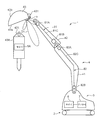
도 1은, 본 발명의 실시 형태에 관한 작업 기계(1)를 도시한다. 당해 작업 기계(1)는 유압 셔블이다. 그러나, 본 발명에 관한 작업 기계는, 예를 들어 유압 크레인과 같은 유압 셔블 이외의 작업 기계여도 된다.1 shows a working machine 1 according to an embodiment of the present invention. The working machine 1 is a hydraulic excavator. However, the working machine according to the present invention may be a working machine other than a hydraulic excavator such as a hydraulic crane.
상기 작업 기계(1)는, 크롤러식 하부 주행체(2)와, 당해 하부 주행체(2) 상에 선회 가능하게 마련된 상부 선회체(3)와, 당해 상부 선회체(3)에 설치된 작업 장치(4)를 구비하고 있다. 상기 하부 주행체(2) 및 상기 상부 선회체(3)는 상기 작업 기계(1)의 기체를 구성한다.The work machine 1 is provided with a crawler type lower traveling
상기 작업 장치(4)는, 작업 장치 본체로서의 붐(41) 및 암(42)과, 어태치먼트(43)를 구비하고 있다. 상기 붐(41)은, 상기 상부 선회체(3)에 대하여 기복 가능하게 설치되어 있다. 상기 암(42)은, 상기 붐(41)의 선단부에 요동 가능하게 연결되어 있다. 구체적으로, 상기 붐(41) 및 상기 암(42)은, 가동 연결부(40)를 통하여 서로 상대 변위 가능하게 되도록 연결되어 있다. 상기 붐(41) 및 상기 암(42)은 기체로부터 어태치먼트까지 순서대로 배열되는 복수의 분할 가동 부재에 상당한다. 상기 어태치먼트(43)는, 상기 암(42)의 선단부에 대하여 요동 가능하게 설치되어 있다.The
상기 작업 장치(4)는, 도시되지 않은 복수의 액추에이터를 더 갖는다. 당해 복수의 액추에이터는, 상기 상부 선회체(3)에 대하여 상기 붐(41)을 기복시키는 액추에이터와, 상기 붐(41)에 대하여 상기 암(42)을 요동시키는 액추에이터와, 상기 암(42)에 대하여 상기 어태치먼트(43)를 요동시키는 액추에이터를 구비하고 있다.The
상기 작업 장치(4)는, 오퍼레이터의 조작에 따라, 상기 붐(41) 및 상기 상부 선회체(3)간의 각도와, 상기 붐(41) 및 상기 암(42)간의 각도와, 상기 암(42) 및 상기 어태치먼트(43)간의 각도를 각각 변경하고, 이에 의해 당해 작업 장치(4)의 자세를 변경한다. 즉, 당해 작업 장치(4)는, 상기 상부 선회체(3)에 대하여 상기 어태치먼트(43)를 상대 변위시키도록 작동한다.The
상기 어태치먼트(43)는 장착부(431)를 구비하고 있다. 당해 장착부(431)는, 상기 암(42)의 선단에 착탈 가능하게 장착되는 부분이다. 도 1에 도시되는 어태치먼트(43)는, 예를 들어 버킷이다. 그러나, 본 발명에 관한 어태치먼트는, 작업 장치 본체에 착탈 가능하게 장착되는 것이면 되며, 예를 들어 브레이커 또는 니블러여도 된다. 예를 들어, 상기 어태치먼트(43) 대신에 도 1에 도시되는 어태치먼트(43A)가 장착되어도 된다. 당해 어태치먼트(43A)는 예를 들어 브레이커이다. 당해 어태치먼트(43A)도 상기 암(42)의 선단에 착탈 가능하게 장착되는 장착부(431)를 갖는다. 이와 같이, 상기 작업 기계(1)에서는, 예를 들어 버킷으로 이루어지는 어태치먼트(43)와, 예를 들어 브레이커로 이루어지는 어태치먼트(43A)가 서로 교환되는 것이 가능하다.The
상기 작업 기계(1)는 발신기(5) 및 발신기(5A)를 더 구비한다. 당해 발신기(5, 5A)는 각각 상기 어태치먼트(43) 및 상기 어태치먼트(43A)에 배치되어 있다. 상기 어태치먼트(43)에 배치된 상기 발신기(5)는 당해 어태치먼트(43)의 식별 정보를 포함하는 정보 신호를 발신한다. 상기 어태치먼트(43A)에 배치된 상기 발신기(5A)는 당해 어태치먼트(43A)의 식별 정보를 포함하는 정보 신호를 발신한다.The working machine (1) further comprises a transmitter (5) and a transmitter (5A). The
도 1에 있어서, 상기 발신기(5)는, 상기 어태치먼트(43)의 면이며 굴삭 작업 시에 지면을 향하는 면(43a)에 있어서, 후단에 가까운 위치(암(42)에 가까운 위치)에 마련되어 있다. 그러나, 그 위치는 한정되지 않는다. 당해 발신기(5)는 당해 면(43a)에 있어서의 선단 근방의 위치에 마련되어도 되고, 상기 어태치먼트(43)의 저면(43b) 상의 적당한 위치에 마련되어도 된다.1, the
도 1에는 발신기(5)의 통신 가능 에어리어(D1)가 도시되어 있다. 당해 통신 가능 에어리어(D1)는, 발신기(5)로부터 발신되는 정보 신호가 도달하는 범위이다. 상기 발신기(5)는 도 2에 도시하는 바와 같은 안테나(501)를 가지며, 상기 통신 가능 에어리어(D1)는 당해 안테나(501)의 지향 특성과 발신기(5)의 발신 출력에 의해 결정된다. 도 1에 도시되는 통신 가능 에어리어(D1)는, 발신기(5)의 방사면의 법선 방향으로 연장되는 메인 로브와, 당해 메인 로브를 사이에 두고 상기 법선 방향에 대하여 경사 방향으로 연장되는 복수의 사이드 로브에 의해 구성된다. 상기 안테나(501)는, 무지향의 지향 특성을 갖는 것이어도 된다.Fig. 1 shows the communicable area D1 of the
상기 작업 기계(1)는, 상기 상부 선회체(3)의 내부에 마련되는 수신기(6) 및 컨트롤러(7)를 더 구비한다. 상기 수신기(6)는, 상기 발신기(5)에 의해 발신된 정보 신호를 수신한다. 상기 컨트롤러(7)는, 상기 작업 기계(1)의 전체 제어를 담당한다.The working machine (1) further comprises a receiver (6) and a controller (7) provided inside the upper revolving structure (3). The receiver (6) receives the information signal transmitted by the transmitter (5). The controller (7) is responsible for the overall control of the working machine (1).
그 밖에, 상부 선회체(3)의 내부에는, 동력원으로서의 엔진과, 상기 엔진에 의해 구동되는 유압 펌프와, 상기 유압 펌프로부터 액추에이터로 토출되는 작동유의 공급량을 조정하는 컨트롤 밸브와, 오퍼레이터로부터의 조작을 받는 조작 레버가 마련되어 있다. 상기 컨트롤러(7)는, 작업 장치(4)를 움직이기 위해 상기 조작 레버에 제공되는 조작의 크기인 조작량에 따라 상기 컨트롤 밸브를 밸브 개방시키고, 이에 의해, 상기 유압 펌프로부터 상기 각 액추에이터로 공급되는 작동유의 유량을 제어한다. 이 제어에 의해, 상기 작업 장치(4)는, 상기 조작량에 따른 자세를 취한다.In addition, inside the upper revolving
도 2는, 도 1에 도시하는 작업 기계(1)에 있어서 통신을 담당하는 구성 요소를 도시하는 블록도이다. 상기 발신기(5)는, 예를 들어 IC 태그로 구성되어 있다. 당해 발신기(5)는, 상기 안테나(501)로부터 상기 어태치먼트(43)의 식별 정보를 포함하는 정보 신호를 외부 공간으로 출력한다. 상기 발신기(5)는, 상기 안테나(501)에 추가하여, 상기 식별 정보를 기억하는 메모리와, 전자 회로를 갖는다. 당해 전자 회로는, 상기 메모리로부터 상기 식별 정보를 판독하고, 그 판독한 식별 정보를 포함하는 발신 데이터를 변조하여 정보 신호를 생성하고, 상기 안테나(501)로부터 출력시킨다.Fig. 2 is a block diagram showing constituent elements responsible for communication in the working machine 1 shown in Fig. 1. Fig. The
상기 IC 태그는, RFID(Radio Frequency Identifier) 태그라고도 칭해지며 내장되는 전지를 동력원으로 하는 액티브형 IC 태그, 및 IC 태그 리더로부터의 전파를 동력원으로 하는 패시브형 IC 태그의 어느 것이어도 된다. 상기 액티브형 IC 태그에는, 진동이나 태양광과 같은 환경 에너지를 전력으로 변환하여, 동력원으로서 사용하는 것도 있다.The IC tag may be either an active IC tag, also referred to as an RFID (Radio Frequency Identifier) tag, which uses an embedded battery as a power source, and a passive IC tag using a radio wave from an IC tag reader as a power source. In the active IC tag, environmental energy such as vibration or sunlight is converted into electric power and used as a power source.
상기 작업 장치(4)는, 유압 셔블 등의 건설 기계로 구성되어 있기 때문에, 이것에 설치되는 상기 IC 태그에는 진동이 발생하기 쉬우며, 또한 태양광의 환경 하에서의 사용이 일반적이다. 이러한 관점에서, 본 실시 형태에서는, 발신기(5)로서 환경 에너지로부터 얻어지는 전력을 동력원으로서 사용하는 액티브형 IC 태그가 채용되고 있다. 그러나, 본 발명은 이것에 한정되지 않는다. 본 발명에 관한 발신기는 패시브형 IC 태그여도 되고, 통상의 전지를 구비하는 액티브형 IC 태그여도 된다. 또한, 본 실시 형태에 관한 상기 발신기(5)는, 일정한 샘플링 간격으로 식별 정보를 포함하는 정보 신호를 발신하는 것이어도 되고, 수신기(6)로부터의 요구에 따라 식별 정보를 포함하는 정보 신호를 발신하는 것이어도 된다.Since the working
상기 식별 정보로서는, 상기 어태치먼트(43)의 종별을 나타내는 정보, 제조 메이커를 나타내는 정보, 일련 번호 및 품번 중 적어도 하나를 포함하는 정보가 채용되는 것이 가능하다. 상기 종별을 나타내는 정보란, 상기 어태치먼트(43)의 종류(예를 들어 버킷, 브레이커)를 나타내는 정보이다.As the identification information, information including at least one of information indicating the type of the
상기 수신기(6)는, 예를 들어 IC 태그 리더로 구성되어 있다. 상세하게는, 당해 수신기(6)는 안테나(61), 증폭기(62), 신호 처리부(63) 및 정보 처리부(64)를 구비하고 있다. 상기 안테나(61)는, 상기 발신기(5)가 발신한 정보 신호를 수신한다. 상기 증폭기(62)는, 수신된 상기 정보 신호를 증폭한다. 상기 신호 처리부(63)는, 증폭된 상기 정보 신호를 복조하고, 발신 데이터를 추출한다. 상기 정보 처리부(64)는, 추출된 상기 발신 데이터를 디코드하고, 이에 의해 상기 식별 정보를 취득하고, 당해 식별 정보를 상기 컨트롤러(7)에 입력한다.The
상기 컨트롤러(7)에 입력된 상기 식별 정보는, 수신 시각과 대응지어져 로그 데이터로서 상기 컨트롤러(7)의 메모리에 축적된다. 당해 메모리에 축적된 상기 로그 데이터는, 소정의 단위 시간(예를 들어 1일) 간격으로 상기 작업 기계(1)의 식별 정보와 대응지어져 통신 네트워크를 통하여 서버(도시 생략)에 송신된다. 이 로그 데이터를 수신한 상기 서버는, 당해 서버 자신의 메모리에 로그 데이터를 축적한다. 당해 서버는, 이러한 로그 데이터를 복수의 작업 기계로부터 수신하여 메모리에 축적한다. 이에 의해, 관리자는, 각 작업 기계(1)에 있어서, 현재, 또는 과거에 있어서 어떠한 어태치먼트(43)가 장착되어 있었는지를 관리할 수 있다.The identification information input to the controller (7) is stored in the memory of the controller (7) as log data associated with the reception time. The log data stored in the memory is transmitted to a server (not shown) through a communication network in association with the identification information of the working machine 1 at intervals of a predetermined unit time (for example, one day). The server receiving the log data stores the log data in the memory of the server itself. The server receives the log data from a plurality of work machines and stores the log data in the memory. Thereby, the manager can manage which
또한, 상기 컨트롤러(7)는 상기 발신기(5)로부터 발신된 식별 정보에 기초하여, 현재 장착되어 있는 어태치먼트(43)를 인식하고, 인식한 어태치먼트(43)에 따른 작업 기계(1)의 제어를 실행한다.The
상기 컨트롤러(7)는, 예를 들어 CPU 등의 프로세서 및 메모리를 구비하는 컴퓨터로 구성된다. 당해 컨트롤러(7)는, 유선에 의해 상기 수신기(6)에 접속되어 있다.The
상기 작업 기계(1)에서는, 상기 작업 장치(4)의 자세에 따라서는, 발신기(5)가 발신한 정보 신호를 수신기(6)가 직접 수신하는 것이 곤란해지는 경우가 있다. 그래서, 상기 작업 기계(1)는 중계 장치(8)를 더 구비한다. 당해 중계 장치(8)는, 상기 발신기(5)로부터 상기 수신기(6)로의 정보 신호의 전달의 중계를 행함으로써, 당해 전달이 가능하게 되는 작업 장치(4)의 자세의 범위를 확대한다.In the working machine 1, depending on the posture of the working
이하, 도 1 및 도 2를 참조하면서, 중계 장치(8)에 대하여 설명한다.Hereinafter, the relay apparatus 8 will be described with reference to Figs. 1 and 2. Fig.
상기 중계 장치(8)는, 상기 발신기(5)로부터 발신되는 상기 정보 신호를 수신하고, 당해 정보 신호를 상기 수신기(6)가 수신 가능한 위치까지 전송한다. 상기 중계 장치(8)는, 상기 작업 장치 본체, 즉 상기 암(42) 및 상기 붐(41)에 의해 주로 구성되는 부분에 배치되어 있다.The relay device 8 receives the information signal transmitted from the
상기 중계 장치(8)는, 복수(본 실시 형태에서는 2개)의 중계 유닛(81, 82)을 포함한다. 당해 중계 장치(8)는, 당해 복수의 중계 유닛(81, 82)에 의한 정보 신호의 발신 및 수신에 의해, 상기 발신기(5)로부터 상기 수신기(6)로의 정보 신호의 전송을 행한다.The relay device 8 includes a plurality of (two in this embodiment)
상기 복수의 중계 유닛(81, 82)은, 발신측 중계 유닛으로서의 중계 유닛(81)과, 수신측 중계 유닛으로서의 중계 유닛(82)을 포함한다. 이하, 이들에 대하여 설명한다.The plurality of relay units (81, 82) includes a relay unit (81) as a source side relay unit and a relay unit (82) as a reception side relay unit. Hereinafter, these will be described.
상기 중계 유닛(81)은, 중계 수신 안테나(81A)와, 중계 발신 안테나(81B)와, 전송 선로(81C)를 포함한다. 상기 중계 수신 안테나(81A)는, 상기 발신기(5)가 발신한 정보 신호를 수신한다. 상기 중계 발신 안테나(81B)는, 상기 중계 수신 안테나(81A)가 수신한 상기 정보 신호를 발신한다. 상기 중계 수신 안테나(81A) 및 상기 중계 발신 안테나(81B)는, 예를 들어 선상 안테나이다.The
상기 전송 선로(81C)는, 상기 중계 수신 안테나(81A)에 의해 수신된 정보 신호를 상기 중계 발신 안테나(81B)에 전송하도록, 상기 중계 수신 안테나(81A)와 상기 중계 발신 안테나(81B)를 서로 접속한다. 당해 전송 선로(81C)의 구체적인 구성은, 유선에 의한 정보 신호의 전송을 가능하게 하는 것이라면, 특별히 한정되지 않는다. 당해 전송 선로(81C)는, 예를 들어 전선이다.The
상기 중계 유닛(81)은, 상기 암(42)에 배치된다. 도 1에 도시하는 예에서는, 상기 중계 유닛(81)은 상기 암(42)의 측면에 배치되어 있다. 그러나, 당해 중계 유닛(81)은, 예를 들어 암(42)에 있어서 지면과 대향하는 면인 당해 암(42)의 하면에 배치되어 있어도 된다.The relay unit (81) is disposed on the arm (42). In the example shown in Fig. 1, the
상기 중계 수신 안테나(81A)는, 상기 발신기(5)가 발신하는 상기 정보 신호를 직접 수신할 수 있도록, 상기 암(42)의 양단부 중 상기 발신기(5)에 가까운 측의 단부에 배치되어 있다. 이에 의해, 발신기(5)로부터 중계 유닛(81)으로의 무선에 의한 정보 신호의 전송이 가능하게 된다.The
상기 중계 발신 안테나(81B)는, 상기 암(42)의 양단부 중 상기 발신기(5)로부터 먼 측의 단부에 배치되어 있다.The
상기 전송 선로(81C)는, 상기 중계 수신 안테나(81A)와 상기 중계 발신 안테나(81B)를 서로 접속하도록, 암(42)을 따라 배치되어 있다. 그 때문에, 상기 중계 수신 안테나(81A)로부터 상기 중계 발신 안테나(81B)까지 유선에 의한, 즉 상기 전송 선로(81C)를 경유한, 정보 신호의 전송이 가능하게 된다.The
상기 중계 유닛(82)은, 중계 수신 안테나(82A)와, 중계 발신 안테나(82B)와, 전송 선로(82C)를 포함한다. 상기 중계 수신 안테나(82A)는, 상기 중계 유닛(81)의 중계 발신 안테나(81B)가 발신한 정보 신호를 수신한다. 상기 중계 발신 안테나(82B)는, 상기 중계 수신 안테나(82A)가 수신한 상기 정보 신호를 발신한다. 상기 중계 수신 안테나(82A) 및 상기 중계 발신 안테나(82B)는, 상기 중계 수신 안테나(81A)나 상기 중계 발신 안테나(82B)와 마찬가지로, 예를 들어 선상 안테나이다.The
상기 전송 선로(82C)는, 상기 중계 수신 안테나(82A)에 의해 수신된 정보 신호를 상기 중계 발신 안테나(82B)에 전송하도록, 중계 수신 안테나(82A)와 중계 발신 안테나(82B)를 서로 접속한다. 당해 전송 선로(82C)의 구체적인 구성은, 유선에 의한 정보 신호의 전송을 가능하게 하는 것이라면, 특별히 한정되지 않는다. 당해 전송 선로(82C)는, 전송 선로(81C)와 마찬가지로, 예를 들어 전선이다.The
상기 중계 유닛(82)은, 상기 붐(41)에 배치된다. 도 1에 도시하는 예에서는, 상기 중계 유닛(82)은 상기 붐(41)의 측면에 배치되어 있다. 그러나, 당해 중계 유닛(82)은, 예를 들어 붐(41)에 있어서 지면과 대향하는 측의 면인 당해 붐(41)의 하면에 배치되어 있어도 된다.The relay unit (82) is disposed in the boom (41). In the example shown in Fig. 1, the
상기 중계 수신 안테나(82A)는, 상기 중계 발신 안테나(81B)가 발신하는 정보 신호를 직접 수신할 수 있도록, 상기 붐(41)의 양단부 중 상기 중계 유닛(81)에 가까운 측의 단부에 배치되어 있다. 이에 의해, 중계 유닛(81)으로부터 중계 유닛(82)으로의 무선에 의한 정보 신호의 전송이 가능하게 된다.The
이와 같이, 본 실시 형태에서는, 상기 중계 유닛(81)이 제1 중계 유닛에 상당하고, 상기 중계 유닛(82)이 제2 중계 유닛에 상당한다. 그리고, 상기 중계 유닛(81)이 배치되는 상기 암(42)이 제1 분할 가동 부재에 상당하고, 상기 중계 유닛(82)이 배치되는 상기 붐(41)이 제2 분할 가동 부재에 상당한다.Thus, in the present embodiment, the
상기 중계 발신 안테나(82B)는, 거기에서 발신되는 상기 정보 신호를 상기 수신기(6)가 직접 수신할 수 있도록, 상기 붐(41)의 양단부 중 상기 수신기(6)에 가까운 측의 단부에 배치된다. 이에 의해, 상기 중계 유닛(82)으로부터 상기 수신기(6)로의 무선에 의한 정보 신호의 전송이 가능하게 된다.The
상기 전송 선로(82C)는, 상기 중계 수신 안테나(82A)와 상기 중계 발신 안테나(82B)를 서로 접속하도록, 상기 붐(41)을 따라 배치되어 있다. 그 때문에, 중계 수신 안테나(82A)로부터 중계 발신 안테나(82B)까지 유선에 의한, 즉 상기 전송 선로(82C)를 경유한, 정보 신호의 전송이 가능하게 된다.The
상기와 같이 중계 유닛(81) 및 중계 유닛(82)이 배치된 상태에서는, 도 3에 도시하는 바와 같이, 상기 중계 발신 안테나(81B)와 상기 중계 수신 안테나(82A)의 사이에, 상기 암(42)과 상기 붐(41)을 상대 변위 가능하게 연결하는 상기 가동 연결부(40)가 위치하고 있다. 즉, 상기 중계 발신 안테나(81B)로부터 상기 중계 수신 안테나(82A)로의 정보 신호의 전송은, 가동 연결부(40)를 통하여 연결되도록 하여 행해진다.3, in a state where the
상기 중계 장치(8)는, 상기 발신기(5)로부터 상기 수신기(6)로의 정보 신호의 전송을 가능하게 하는 중계를 행한다. 이것은, 발신기로부터 수신기로의 직접적인 정보 신호의 전송밖에 행할 수 없는 종래의 작업 기계와 비교하여, 상기 발신기(5)로부터 상기 수신기(6)로의 정보 신호의 전달이 가능하게 되는 작업 장치(4)의 자세인 전달 가능 자세의 범위를 확대하는 것을 가능하게 한다.The relay device 8 performs relaying to enable transmission of an information signal from the
상기 복수의 중계 유닛(81, 82)은, 서로 직렬로 배치되면서 이들 순서로 상기 발신기(5)로부터 상기 수신기(6)로의 직렬적인 정보 신호의 전송을 행한다. 이것은, 상기 전달 가능 자세의 범위를 더 확대하는 것을 가능하게 한다.The plurality of
또한, 상기 복수의 중계 유닛(81, 82)의 각각의 전송 선로(80C)는 상기 가동 연결부(40)를 걸치는 것을 피하도록 배치되어 있고, 당해 가동 연결부(40)의 움직임에 지장을 주지 않고, 상기 복수의 중계 유닛(81, 82)은 상기 발신기(5)로부터 상기 수신기(6)로 정보 신호를 전달하기 위한 중계를 행할 수 있다.Each of the transmission lines 80C of the plurality of
또한, 작업 기계(1)에 있어서는, 중계 발신 안테나(81C)로부터 중계 수신 안테나(82A)까지의 거리를 짧게 하면서, 중계 유닛(81) 및 중계 유닛(82)의 각각에 있어서 유선의 통신을 행하는 전송 선로(81C, 82C)의 길이를 크게 할 수 있다. 이것은, 상기 중계 유닛(81) 및 상기 중계 유닛(82)의 각각의 소비 전력을 억제하면서, 상기 가동 연결부(40)를 통하여 연결되는 정보 신호의 전달을 하기 위한 중계를 확실하게 행할 수 있다.In the working machine 1, while the distance from the
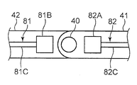
도 4는, 상기 실시 형태의 변형예를 도시한다. 이 변형예에서는, 상기 실시 형태에 관한 상기 중계 수신 안테나(8A), 상기 중계 발신 안테나(8B) 및 상기 전송 선로(8C)가 동일 평면 상에 형성되어 있다.Fig. 4 shows a modification of the above embodiment. In this modified example, the relay reception antenna 8A, the relay transmission antenna 8B, and the transmission line 8C according to the above embodiment are formed on the same plane.
도 4에 도시되는 상기 변형예에서는, 상기 중계 수신 안테나(8A), 상기 중계 발신 안테나(8B) 및 상기 전송 선로(8C)의 각각이 작업 장치 본체의 표면에 형성되어 있다. 구체적으로, 상기 중계 유닛(81)에 포함되는 상기 중계 수신 안테나(8A), 상기 중계 발신 안테나(8B) 및 상기 전송 선로(8C)는 모두 상기 암(42)의 표면에 형성되고, 상기 중계 유닛(82)에 포함되는 상기 중계 수신 안테나(8A), 상기 중계 발신 안테나(8B) 및 상기 전송 선로(8C)는 상기 붐(41)의 표면에 형성되어 있다.In the modification shown in Fig. 4, each of the relay receiving antenna 8A, the relay originating antenna 8B, and the transmission line 8C is formed on the surface of the working device body. Specifically, the relay receiving antenna 8A, the relay transmitting antenna 8B, and the transmission line 8C included in the
상기 암(42) 및 상기 붐(41)의 각각의 표면은, 당해 암(42) 및 당해 붐(41)의 모체를 구성하는 금속재(400)의 표면을 덮는 피복막(401)에 의해 구성되어 있다. 당해 피복막(401)은, 높은 절연성(즉, 높은 유전율)을 갖고 있다. 당해 피복막(401)은, 예를 들어 상기 금속재(400)의 표면에 도포되는 도료이다. 당해 피복막(401)은, 전자파의 파장의 1/10보다 작은 두께를 갖는다.Each of the surfaces of the
상기 변형예에 관한 상기 중계 유닛(81) 및 상기 중계 유닛(82)은, 각각 마이크로스트립 구성을 갖고 있다. 즉, 상기 중계 수신 안테나(8A) 및 상기 중계 발신 안테나(8B)는 평면 안테나이며, 상기 전송 선로(8C)는 도전막이다.The
상기 변형예에 따르면, 상기 중계 수신 안테나(8A), 상기 중계 발신 안테나(8B) 및 상기 전송 선로(8C)의 각각의 두께를 현저하게 작게 할 수 있고, 이에 의해, 당해 중계 수신 안테나(8A), 당해 중계 발신 안테나(8B) 및 당해 전송 선로(8C)가 상기 암(42) 또는 상기 붐(41)의 표면으로부터의 높이를 현저하게 작게 할 수 있다. 이것은, 상기 작업 기계(1)에 의한 작업 중에서의 상기 전송 선로(8C)의 단선이나 상기 중계 수신 안테나(8A) 및 상기 중계 발신 안테나(8B)의 파손 가능성을 낮게 하는 것을 가능하게 한다.The thickness of each of the relay receiving antenna 8A, the relay originating antenna 8B and the transmission line 8C can be remarkably reduced. Thus, the relay receiving antenna 8A, And the height of the relay transmitting antenna 8B and the transmission line 8C from the surface of the
또한, 상기 중계 수신 안테나(8A), 상기 중계 발신 안테나(8B) 및 상기 전송 선로(8C)의 각각은, 상기 암(42) 또는 상기 붐(41)의 표면에 직접 형성되어 있으므로, 예를 들어 당해 중계 수신 안테나(8A), 당해 중계 발신 안테나(8B) 및 당해 전송 선로(8C)의 각각이 암(42) 또는 붐(41)의 표면에 별도로 설치되는 경우와 비교하여, 당해 중계 수신 안테나(8A), 당해 중계 발신 안테나(8B) 및 당해 전송 선로(8C)의 암(42) 또는 붐(41)의 표면으로부터의 돌출을 억제할 수 있다.Since each of the relay receiving antenna 8A, the relay transmitting antenna 8B and the transmission line 8C is directly formed on the surface of the
상기 실시 형태 및 그의 변형예는 예시이며, 본 발명을 한정하는 것은 아니다.The above-described embodiment and its modified examples are illustrative and do not limit the present invention.
예를 들어, 본 발명에 관한 어태치먼트는, 버킷이나 니블러 등과 같이, 작업 장치의 선단에 배치되는 것에 한정되지 않는다. 예를 들어, 암이 붐에 대하여 착탈 가능하게 배치되어 있는 경우에는, 버킷이나 니블러 등과 같이 암에 대하여 착탈 가능한 작업용 어태치먼트뿐만 아니라 당해 암도 본 발명의 어태치먼트에 상당하는 양태가 존재할 수 있다.For example, the attachment according to the present invention is not limited to being disposed at the tip of the working device, such as a bucket or a nibbler. For example, in the case where the arm is detachably arranged with respect to the boom, there may be an aspect corresponding to the attachment of the present invention as well as the work attachment, which is detachable from the arm such as a bucket or a nibbler.
서로 연결되는 붐 및 암 중 붐이 본 발명에 관한 어태치먼트에 상당하고, 적어도 암이 본 발명에 관한 작업 장치 본체에 상당하는 양태도 존재할 수 있다. 즉, 본 발명에 관한 작업 장치 본체는, 기체에 대하여 직접 설치되어 있어도 되고, 다른 부재(예를 들어, 어태치먼트)를 통하여 기체에 설치되어 있어도 된다. 요컨대, 본 발명의 작업 장치는, 작업 장치 본체와, 기체에 대하여 변위 가능하며, 또한 상기 작업 장치 본체에 대하여 착탈 가능한 어태치먼트를 포함하고 있으면 된다.There may be an aspect in which the boom and the arm boom connected to each other correspond to the attachment according to the present invention and at least the arm corresponds to the working apparatus main body according to the present invention. That is, the main body of the working apparatus according to the present invention may be provided directly on the base body or may be provided on the base body through another member (for example, an attachment). In short, the working apparatus of the present invention may include a working apparatus main body, and an attachment capable of being displaced with respect to the base body and detachable with respect to the working apparatus main body.
본 발명에 관한 붐은, 서로 독립된 부재인 복수의 분할 붐으로 이루어지는 것이어도 된다. 상기 복수의 분할 붐이 서로 직렬로 배치되는 3 이상의 분할 붐인 경우, 양단의 분할 붐의 사이에 배치된 분할 붐(인서트 붐)이 본 발명에 관한 어태치먼트에 상당하는 것도 가능하다.The boom according to the present invention may be composed of a plurality of divided booms which are independent members. When the plurality of divided booms are three or more divided booms arranged in series with each other, a divided boom (insert boom) disposed between the divided booms at both ends may correspond to the attachment according to the present invention.
본 발명에 관한 작업 기계는, 유압 셔블 이외의 작업 기계, 예를 들어 크레인이어도 된다. 당해 크레인은, 예를 들어 타워 크레인이다. 타워 크레인은, 예를 들어 크롤러 벨트 주행식 크레인 본체(기체)와, 이것에 설치되는 타워나 타워 지브 등의 어태치먼트를 구비한다. 구체적으로, 상기 타워는, 상기 크레인 본체의 전방부에 기복 가능하게 설치되고, 그 기복 방향으로 타워 기복 로프에 의해 조작된다. 상기 타워 지브는, 상기 타워의 선단에 기복 가능하게 설치되고, 그 기복 방향으로 지브 기복 로프에 의해 조작된다.The working machine according to the present invention may be a working machine other than a hydraulic excavator, for example, a crane. This crane is, for example, a tower crane. The tower crane includes, for example, an attachment such as a crawler belt traveling type crane main body (base) and a tower or tower jib installed on the main body. Specifically, the tower is reliably provided on the front portion of the crane body, and is operated by the tower relief rope in the underside direction. The tower jig is provided so as to be capable of retracting from the tip of the tower, and is operated by the jib relief rope in the underside direction.
본 발명에 관한 중계 장치는 단일의 중계 유닛만을 포함하는 것이어도 된다. 당해 단일의 중계 유닛은, 발신기에 의해 발신된 정보 신호를 직접 수신하는 중계 수신 안테나와, 그 수신한 정보 신호를 발신하여 수신기에 수신시키는 중계 발신 안테나를 가짐으로써, 상기 정보 신호의 중계가 가능하다.The relay apparatus according to the present invention may include only a single relay unit. The single relay unit has a relay reception antenna for directly receiving the information signal transmitted by the transmitter and a relay transmission antenna for transmitting the received information signal to the receiver so that the information signal can be relayed .
본 발명에 있어서, 작업 장치 본체를 구성하는 복수의 분할 가동 부재(상기 실시 형태에서는 상기 암(42) 및 상기 붐(41))의 수와, 중계 유닛의 수는, 서로 일치하지 않아도 된다. 예를 들어, 상기 복수의 분할 가동 부재가 긴 분할 가동 부재를 포함하는 경우, 당해 긴 분할 가동 부재에 2 이상의 중계 유닛이 배치되어 있어도 된다.In the present invention, the number of the divided movable members (the
본 발명에 관한 복수의 중계 유닛은, 발신측 중계 유닛 및 수신측 중계 유닛에 추가하여 이들 이외의 적어도 하나의 중계 유닛(다른 중계 유닛)을 더 포함하고 있어도 된다. 당해 적어도 하나의 다른 중계 유닛은, 상기 발신측 중계 유닛과 상기 수신측 중계 유닛의 사이에 위치하고, 상기 발신측 중계 유닛으로부터 상기 수신측 중계 유닛으로의 정보 신호의 전송을 중계할 수 있도록 배치되는 것이 바람직하다.The plurality of relay units according to the present invention may further include at least one relay unit (another relay unit) other than the source side relay unit and the reception side relay unit. The at least one other relay unit is disposed between the source relay station and the receiver relay station so as to be able to relay the transmission of the information signal from the source relay station to the receiver relay station desirable.
본 발명에 관한 복수의 중계 유닛은, 서로 직렬로 배치되는 3 이상의 중계 유닛을 포함해도 된다. 이 경우, 상기 복수의 중계 유닛 중 양단에 위치하는 중계 유닛 이외의 중계 유닛의 각각은, 당해 중계 유닛의 하류측에 위치하는 중계 유닛에 대하여 정보 신호를 발신하는 제1 중계 유닛으로서 기능함과 함께, 상류측에 위치하는 중계 유닛으로부터 발신된 정보 신호를 수신하는 제2 중계 유닛으로서 기능한다.The plurality of relay units according to the present invention may include three or more relay units arranged in series with each other. In this case, each of the relay units other than the relay units located at both ends of the plurality of relay units functions as a first relay unit that transmits an information signal to the relay unit located on the downstream side of the relay unit concerned , And functions as a second relay unit for receiving the information signal transmitted from the relay unit located on the upstream side.
본 발명에 관한 작업 기계가 복수의 중계 유닛을 포함하는 경우, 당해 복수의 중계 유닛은 서로 병렬로 배치되어 있어도 된다. 즉, 발신기와 수신기의 사이에 서로 병렬의 복수의 정보 신호의 전송 경로를 형성하도록 상기 복수의 중계 유닛이 배치되어 있어도 된다. 이 경우, 상기 발신기로부터 발신된 정보 신호는, 병렬로 배치된 중계 유닛 중 어느 것을 통하여 수신기에 전송된다. 상기 복수의 전송 경로의 각각은, 단일의 중계 유닛에 의해 실현되는 것이어도 되고, 서로 직렬로 배치된 복수의 중계 유닛에 의해 실현되는 것이어도 된다.When the working machine according to the present invention includes a plurality of relay units, the plurality of relay units may be arranged in parallel with each other. That is, the plurality of relay units may be arranged so as to form a transmission path of a plurality of information signals in parallel between the transmitter and the receiver. In this case, the information signal transmitted from the transmitter is transmitted to the receiver through any of the relay units arranged in parallel. Each of the plurality of transmission paths may be realized by a single relay unit or may be realized by a plurality of relay units arranged in series with each other.
본 발명에 관한 중계 수신 안테나, 중계 발신 안테나 및 전송 선로는 공통의 판상 부재의 표면에 형성되어도 된다. 이 경우, 당해 판상 부재를 작업 장치 본체에 설치함으로써, 상기 중계 수신 안테나, 상기 중계 발신 안테나 및 상기 전송 선로를 상기 작업 장치 본체에 배치하는 것이 가능하다.The relay receiving antenna, relay transmitting antenna, and transmission line according to the present invention may be formed on the surface of a common plate member. In this case, it is possible to dispose the relay receiving antenna, the relay originating antenna, and the transmission line on the working apparatus main body by installing the plate member on the working apparatus main body.
이상과 같이, 기체와, 착탈 가능한 어태치먼트를 포함하고, 기체에 대하여 어태치먼트를 상대적으로 변위시키도록 작동하는 작업 장치를 구비한 작업 기계이며, 상기 어태치먼트로부터 상기 기체에 대하여 무선 통신에 의해 당해 어태치먼트에 관한 정보를 전달하는 것이 가능하며, 또한 그 전달이 가능한 작업 장치의 자세인 전달 가능 자세의 범위를 확대하는 것이 가능한 작업 기계가 제공된다. 당해 작업 기계는, 기체와, 상기 기체에 설치되는 작업 장치 본체 및 상기 작업 장치 본체에 대하여 착탈 가능한 어태치먼트를 포함하며, 또한 상기 기체에 대하여 상기 어태치먼트를 상대 변위시키도록 작동하는 작업 장치와, 상기 어태치먼트와 함께 상기 기체에 대하여 상대 변위하도록 상기 어태치먼트에 배치되고, 상기 어태치먼트에 관한 정보를 포함하는 정보 신호를 발신하는 발신기와, 상기 기체에 배치되고, 상기 정보 신호를 수신하는 것이 가능한 수신기와, 상기 수신기가 수신한 상기 정보 신호에 기초하여, 상기 어태치먼트에 관한 정보를 취득하는 컨트롤러와, 상기 작업 장치 본체에 마련되고, 상기 발신기로부터 발신되는 상기 정보 신호를 수신하여 상기 정보 신호를 상기 수신기가 수신 가능한 위치까지 전송하는 중계 장치를 구비한다.As described above, there is provided a working machine including a base and a detachable attachment, the working machine being operative to relatively displace the attachment with respect to the base body, wherein the base is detachable from the attachment with respect to the attachment There is provided a work machine capable of transmitting information and expanding the range of the deliverable attitude, which is the attitude of the work device capable of delivering the information. The working machine includes a working device that includes a base, a working device body mounted on the base, and an attachment detachable from the working device body, the working device being operative to relatively displace the attachment with respect to the base; A receiver disposed in the attachment to be displaced with respect to the base with an information signal, the base station comprising: a transmitter, which is disposed in the attachment and that transmits an information signal including information about the attachment; a receiver disposed in the base and capable of receiving the information signal; And a control unit which is provided in the main body of the working apparatus and receives the information signal transmitted from the transmitter and outputs the information signal to a position at which the receiver can receive the information signal, To the relay apparatus.
상기 중계 장치는, 당해 중계 장치가 상기 작업 장치 본체에 마련되는 위치에서, 어태치먼트에 배치된 발신기로부터 기체에 마련된 수신기로의 정보 신호의 전달을 가능하게 하는 중계를 행함으로써, 발신기로부터 수신기로의 직접적인 정보 신호의 전달밖에 행할 수 없는 종래의 작업 기계와 비교하여, 당해 전달이 가능하게 되는 작업 장치의 자세의 범위를 확대하는 것을 가능하게 한다.The relay device performs relaying to enable transmission of the information signal from the transmitter placed in the attachment to the receiver provided in the attachment at the position where the relay device is provided in the main body of the working device, It is possible to expand the range of the posture of the work device that can be delivered as compared with the conventional work machine that can only carry information signals.
상기 중계 장치는, 적어도 하나의 중계 유닛을 포함하고, 상기 적어도 하나의 중계 유닛은, 상기 정보 신호를 수신 가능한 중계 수신 안테나와, 상기 정보 신호를 발신 가능한 중계 발신 안테나와, 상기 중계 수신 안테나에 의해 수신된 상기 정보 신호를 상기 중계 발신 안테나에 전송하도록 상기 중계 수신 안테나와 상기 중계 발신 안테나를 연결하는 전송 선로를 갖고, 상기 적어도 하나의 중계 유닛에 의한 수신 및 발신에 의해 상기 발신기로부터 상기 수신기로의 상기 정보 신호의 전달을 가능하게 하는 것이 바람직하다.Wherein the relay apparatus includes at least one relay unit, and the at least one relay unit includes: a relay receiving antenna capable of receiving the information signal; a relaying transmitting antenna capable of transmitting the information signal; And a transmission line for connecting the relaying antenna and the relaying antenna so as to transmit the received information signal to the relaying antenna, wherein the relaying unit is configured to transmit the information signal from the transmitter to the receiver by reception and transmission by the at least one relaying unit Thereby enabling transmission of the information signal.
또한, 상기 적어도 하나의 중계 유닛이 복수의 중계 유닛을 포함함으로써, 상기 발신기로부터 상기 수신기로의 상기 정보 신호의 전달이 가능하게 되는 상기 작업 장치의 자세의 범위를 보다 확대하는 것이 가능하게 된다. 구체적으로, 상기 복수의 중계 유닛은, 상기 복수의 중계 유닛 중 상기 발신기에 가장 가까운 위치에 마련되는 발신측 중계 유닛이며 상기 발신측 중계 유닛의 상기 중계 수신 안테나가 상기 발신기로부터 발해지는 상기 정보 신호를 직접 수신하는 것이 가능한 위치에 배치되는 발신측 중계 유닛과, 상기 복수의 중계 유닛 중 상기 수신기에 가장 가까운 위치에 마련되는 수신측 중계 유닛이며 상기 수신측 중계 유닛의 상기 중계 발신 안테나로부터 발해지는 상기 정보 신호를 상기 수신기가 직접 수신하는 것이 가능한 위치에 배치되는 수신측 중계 유닛을 포함하고, 상기 발신측 중계 유닛의 상기 중계 발신 안테나로부터 발해지는 상기 정보 신호가 상기 수신측 중계 유닛의 상기 중계 수신 안테나에 직접 혹은 다른 중계 유닛을 통하여 전달되는 것이 적합하다.Further, the at least one relay unit includes a plurality of relay units, thereby making it possible to further expand the range of the posture of the work device in which the information signal can be transmitted from the transmitter to the receiver. Specifically, it is preferable that the plurality of relay units include: a transmitting-side relay unit provided at a position closest to the transmitter among the plurality of relay units, and the relay receiving antenna of the transmitting-side relay unit transmits the information signal transmitted from the transmitter A receiving side relay unit disposed at a position where direct reception is possible, a receiving side relay unit provided at a position closest to the receiver among the plurality of relay units, wherein the information transmitted from the relay originating antenna of the receiving side relay unit Side relay unit, wherein the information signal transmitted from the relay originating antenna of the originating relay unit is transmitted to the relay reception antenna of the reception relay unit Directly or through other relay units Suitable.
이 양태에 관한 상기 중계 장치는, 상기 발신측 중계 유닛 및 상기 수신측 중계 유닛을 포함함으로써, 적어도 2개의 중계 유닛을 매개로 하는 발신기로부터 수신기로의 직렬적인 정보 신호의 전달을 행하는 것이 가능하고, 이에 의해, 상기 전달 가능 자세의 범위를 더 확대하는 것을 가능하게 한다.The relay apparatus according to this aspect is capable of transmitting serial information signals from a transmitter to a receiver via at least two relay units by including the caller side relay unit and the receiver side relay unit, This makes it possible to further extend the range of the deliverable posture.
상기 작업 장치 본체가 상기 기체로부터 상기 어태치먼트까지 순서대로 배열되는 복수의 분할 가동 부재를 포함하고, 상기 복수의 분할 가동 부재 중 서로 인접하는 분할 가동 부재가 가동 연결부를 통하여 상대 변위 가능하게 되도록 연결되어 있는 경우, 상기 복수의 중계 유닛은, 제1 중계 유닛 및 제2 중계 유닛을 포함하고, 상기 제1 중계 유닛의 상기 중계 발신 안테나로부터 발신되는 상기 정보 신호가 상기 제2 중계 유닛의 상기 중계 수신 안테나에 직접 수신되도록 상기 제1 및 제2 중계 유닛이 상기 복수의 분할 가동 부재 중 제1 분할 가동 부재 및 상기 제1 분할 가동 부재와 인접하는 제2 분할 가동 부재에 각각 설치되는 것이 바람직하다. 이 배치는, 상기 제1 및 제2 중계 유닛의 전송 선로가 상기 가동 연결부를 걸쳐 배치되는 것을 피하는 것을 가능하게 하고, 이에 의해, 상기 가동 연결부의 움직임에 지장을 주지 않고 상기 복수의 중계 유닛에 의해 발신기로부터 수신기로의 정보 신호의 전달의 중계를 행하는 것을 가능하게 한다.Wherein the working device body includes a plurality of divided movable members arranged in order from the base to the attachment, and the divided movable members adjacent to each other of the plurality of divided movable members are connected to be movable relative to each other via the movable connecting portion The plurality of relay units include a first relaying unit and a second relaying unit and the information signal transmitted from the relaying originating antenna of the first relaying unit is transmitted to the relaying antenna of the second relaying unit It is preferable that the first and second relay units are installed respectively in the first divided movable member and the second divided movable member adjacent to the first divided movable member and the first divided movable member so as to be directly received. This arrangement makes it possible to avoid that the transmission lines of the first and second relay units are arranged over the movable connection portion, thereby preventing the movable connection portion from being moved by the plurality of relay units It is possible to relay the transmission of the information signal from the transmitter to the receiver.
보다 구체적으로, 상기 제1 중계 유닛의 상기 중계 발신 안테나는 상기 제1 분할 가동 부재의 양단부 중 상기 제2 분할 가동 부재에 가까운 측의 단부에 배치되고, 상기 제1 중계 유닛의 상기 중계 수신 안테나는 상기 제1 분할 가동 부재의 양단부 중 상기 제2 분할 가동 부재로부터 먼 측의 단부에 배치되고, 상기 제2 중계 유닛의 상기 중계 수신 안테나는 상기 제2 분할 가동 부재의 양단부 중 상기 제1 분할 가동 부재에 가까운 측의 단부에 배치되고, 상기 제2 중계 유닛의 상기 중계 발신 안테나는 상기 제2 분할 가동 부재의 양단부 중 상기 제1 분할 가동 부재로부터 먼 측의 단부에 배치되고, 상기 제1 중계 유닛의 상기 전송 선로는 당해 제1 중계 유닛의 상기 중계 발신 안테나와 상기 중계 수신 안테나를 연결하도록 상기 제1 분할 가동 부재를 따라 배치되고, 상기 제2 중계 유닛의 상기 전송 선로는 당해 제2 중계 유닛의 상기 중계 발신 안테나와 상기 중계 수신 안테나를 연결하도록 상기 제2 분할 가동 부재를 따라 배치되는 것이 바람직하다.More specifically, the relaying originating antenna of the first relaying unit is disposed at an end of the both ends of the first movable movable member close to the second movable movable member, and the relay receiving antenna of the first relaying unit And the relay receiving antenna of the second relaying unit is disposed at an end of the first divided movable member which is farther from the second divided movable member than at both ends of the first divided movable member, And the relaying originating antenna of the second relaying unit is disposed at an end of the opposite end of the second movable member that is distant from the first movable member, The transmission line is disposed along the first movable member so as to connect the relaying antenna of the first relay unit to the relaying antenna And said second transmission line of the repeater unit is preferably disposed along the second dividing the movable member to connect said outbound relay antenna and the relay receive antenna of that second relay unit.
이러한 제1 및 제2 중계 유닛의 배치는, 상기 제1 중계 유닛의 상기 중계 발신 안테나로부터 상기 제2 중계 유닛의 상기 중계 수신 안테나까지의 거리를 짧게 하며, 또한 상기 제1 및 제2 중계 유닛 중 유선의 통신을 행하는 전송 선로의 길이를 크게 취하는 것을 가능하게 하고, 이에 의해, 상기 제1 및 제2 중계 유닛의 각각의 소비 전력을 억제하면서 가동 연결부를 통하여 연결되는 정보 신호의 전달의 중계를 확실하게 행하는 것을 가능하게 한다.The arrangement of the first and second relay units may be such that the distance from the relaying transmitting antenna of the first relaying unit to the relaying antenna of the second relaying unit is shortened and the distance between the first relaying unit and the second relaying unit It is possible to increase the length of the transmission line for performing the communication of the wired line and thereby ensure the relay of the transmission of the information signal connected through the movable connection portion while suppressing the power consumption of each of the first and second relay units .
바람직하게는, 상기 전송 선로는, 소정의 평면 상에 형성된 도전막이며, 상기 중계 수신 안테나 및 상기 중계 발신 안테나는, 각각 상기 소정의 평면 상에 형성된 평면 안테나이다. 이와 같이 도전막으로 이루어지는 전송 선로, 그리고 각각이 평면 안테나인 중계 수신 안테나 및 중계 발신 안테나는 모두, 작은 두께를 가짐으로써, 당해 전송 선로, 당해 중계 수신 안테나 및 당해 중계 발신 안테나의 상기 소정의 표면으로부터의 높이를 작게 할 수 있다. 이것은, 상기 작업 기계에 의한 작업 중에서의 전송 선로의 단선이나 중계 수신 안테나 및/또는 중계 발신 안테나의 파손 가능성을 낮게 한다.Preferably, the transmission line is a conductive film formed on a predetermined plane, and the relay receiving antenna and the relaying transmitting antenna are each a plane antenna formed on the predetermined plane. The transmission line made of the conductive film and the relay receiving antenna and the relaying transmitting antenna, each of which is a plane antenna, have a small thickness, so that the transmission line, the relay receiving antenna, and the relay transmitting antenna Can be made smaller. This lowers the possibility of disconnection of the transmission line and breakage of the relay reception antenna and / or the relay transmission antenna during operation by the working machine.
상기 소정의 평면은, 예를 들어 상기 작업 장치 본체의 표면인 것이 바람직하다. 이와 같이, 상기 전송 선로, 상기 중계 수신 안테나 및 상기 중계 발신 안테나의 각각이 상기 작업 장치 본체의 표면 상에 형성되는 것은, 당해 전송 선로, 당해 중계 수신 안테나 및 당해 중계 발신 안테나의 각각이 작업 장치 본체와는 다른 부재에 설치되는 경우와 비교하여, 당해 전송 선로, 당해 중계 수신 안테나 및 당해 중계 발신 안테나의 각각의 작업 장치 본체의 표면으로부터의 높이를 더 삭감하는 것을 가능하게 한다. 이것은, 작업 기계에 의한 작업 중에서의 전송 선로의 단선이나 중계 수신 안테나 및/또는 중계 발신 안테나의 파손을 보다 확실하게 피하는 것을 가능하게 한다.Preferably, the predetermined plane is, for example, the surface of the working device body. As described above, the transmission line, the relay reception antenna, and the relay transmission antenna are formed on the surface of the working device body, respectively, because the transmission line, the relay reception antenna, It is possible to further reduce the height of the transmission line, the relay reception antenna, and the relay transmission antenna from the surface of each working device body, as compared with the case where the transmission line, the relay reception antenna and the relay transmission antenna are provided. This makes it possible to reliably avoid disconnection of the transmission line and breakage of the relay reception antenna and / or the relay transmission antenna during operation by the working machine.
Claims (7)
기체와,
상기 기체에 설치되는 작업 장치 본체 및 상기 작업 장치 본체에 대하여 착탈 가능한 어태치먼트를 포함하며, 또한 상기 기체에 대하여 상기 어태치먼트를 상대 변위시키도록 작동하는 작업 장치와,
상기 어태치먼트와 함께 상기 기체에 대하여 상대 변위하도록 상기 어태치먼트에 배치되고, 상기 어태치먼트에 관한 정보를 포함하는 정보 신호를 발신하는 발신기와,
상기 기체에 배치되고, 상기 정보 신호를 수신하는 것이 가능한 수신기와,
상기 수신기가 수신한 상기 정보 신호에 기초하여, 상기 어태치먼트에 관한 정보를 취득하는 컨트롤러와,
상기 작업 장치 본체에 마련되고, 상기 발신기로부터 발신되는 상기 정보 신호를 수신하여 상기 정보 신호를 상기 수신기가 수신 가능한 위치까지 전송하는 중계 장치를 구비하는, 작업 기계.Work machine,
The gas,
A working device that includes a working device body mounted on the base and an attachment detachable from the working device body and operative to relatively displace the attachment with respect to the base;
A transmitter disposed in the attachment so as to be displaced relative to the base with the attachment, the transmitter transmitting an information signal including information about the attachment;
A receiver disposed in the base and capable of receiving the information signal;
A controller for acquiring information on the attachment based on the information signal received by the receiver;
And a relay device which is provided in the main body of the work machine and receives the information signal transmitted from the transmitter and transmits the information signal to a position where the receiver can receive the information signal.
Applications Claiming Priority (2)
| Application Number | Priority Date | Filing Date | Title |
|---|---|---|---|
| JP2017207893A JP2019078131A (en) | 2017-10-27 | 2017-10-27 | Work machine |
| JPJP-P-2017-207893 | 2017-10-27 |
Publications (1)
| Publication Number | Publication Date |
|---|---|
| KR20190047613A true KR20190047613A (en) | 2019-05-08 |
Family
ID=63720552
Family Applications (1)
| Application Number | Title | Priority Date | Filing Date |
|---|---|---|---|
| KR1020180126722A KR20190047613A (en) | 2017-10-27 | 2018-10-23 | Work machine |
Country Status (5)
| Country | Link |
|---|---|
| US (1) | US10662622B2 (en) |
| EP (1) | EP3480373B1 (en) |
| JP (1) | JP2019078131A (en) |
| KR (1) | KR20190047613A (en) |
| CN (1) | CN109723100A (en) |
Families Citing this family (2)
| Publication number | Priority date | Publication date | Assignee | Title |
|---|---|---|---|---|
| US11314223B2 (en) | 2019-10-31 | 2022-04-26 | Caterpillar Inc. | Work tool data system and method thereof |
| EP4180586A1 (en) * | 2020-07-08 | 2023-05-17 | Kobelco Construction Machinery Co., Ltd. | Work machine, program, and method for controlling work machine |
Family Cites Families (14)
| Publication number | Priority date | Publication date | Assignee | Title |
|---|---|---|---|---|
| US2741601A (en) * | 1951-09-04 | 1956-04-10 | Jr Paul B Maccready | Cloud seeding generator |
| US3263141A (en) * | 1963-02-26 | 1966-07-26 | Kaman Aircraft Corp | Radio controlled plural motor crane control system |
| US3408546A (en) * | 1965-06-07 | 1968-10-29 | Barrett Electronics Corp | Crane command circuit having check means for detecting relay malfunction |
| JPH10237904A (en) | 1997-02-25 | 1998-09-08 | Shin Caterpillar Mitsubishi Ltd | Method of controlling construction machinery and device thereof |
| US6779469B1 (en) * | 2003-08-04 | 2004-08-24 | Advanta Technology Inc | Seeding apparatus |
| US20070040353A1 (en) * | 2005-08-16 | 2007-02-22 | Jolain Dallaire | Off-road dolly for displacement of a trailer in an off-road environment |
| US20090198409A1 (en) | 2008-01-31 | 2009-08-06 | Caterpillar Inc. | Work tool data system |
| KR101559174B1 (en) | 2008-12-24 | 2015-10-13 | 두산인프라코어 주식회사 | Flow rate control device for construction machinery |
| US8849186B2 (en) * | 2009-05-12 | 2014-09-30 | Qualcomm Incorporated | Repeater communication using inserted low power sequences |
| JP5535176B2 (en) * | 2011-11-04 | 2014-07-02 | 株式会社小松製作所 | Mining machinery dynamics management system |
| JP6267783B2 (en) * | 2016-02-01 | 2018-01-24 | 株式会社小松製作所 | Work machine control system, work machine, and work machine management system |
| US9744904B1 (en) * | 2016-02-09 | 2017-08-29 | Corinne Tolliver | Vehicle alarm |
| CN107338826A (en) | 2016-04-28 | 2017-11-10 | 东空销售股份有限公司 | Annex monitoring system |
| US10725445B2 (en) * | 2016-11-11 | 2020-07-28 | Safe Tek, LLC | Systems, methods, and articles of manufacture for operation of an industrial machine |
-
2017
- 2017-10-27 JP JP2017207893A patent/JP2019078131A/en active Pending
-
2018
- 2018-09-27 US US16/143,667 patent/US10662622B2/en active Active
- 2018-10-01 EP EP18197906.3A patent/EP3480373B1/en active Active
- 2018-10-23 CN CN201811239702.XA patent/CN109723100A/en active Pending
- 2018-10-23 KR KR1020180126722A patent/KR20190047613A/en unknown
Also Published As
| Publication number | Publication date |
|---|---|
| EP3480373A1 (en) | 2019-05-08 |
| JP2019078131A (en) | 2019-05-23 |
| US10662622B2 (en) | 2020-05-26 |
| US20190127957A1 (en) | 2019-05-02 |
| EP3480373B1 (en) | 2021-06-09 |
| CN109723100A (en) | 2019-05-07 |
Similar Documents
| Publication | Publication Date | Title |
|---|---|---|
| CN1735847B (en) | Wireless communication | |
| CN100493237C (en) | Mobile wireless communications device comprising a satellite positioning system antenna and electrically conductive director element therefor | |
| KR20190047613A (en) | Work machine | |
| EP2560233A2 (en) | Mobile terminal | |
| CN104852122A (en) | Electronic equipment and antenna device | |
| EP1344367A2 (en) | Address sharing | |
| CN101218710A (en) | Improved forwarding antenna for point-to-point application | |
| EP2398158A3 (en) | Method of controlling a plurality of internal antennas in a mobile communication device | |
| CN105704846B (en) | Follow-up tracking WIFI transmission device and control method thereof | |
| CN104641509A (en) | Antenna of mobile communication base station and method for controlling same | |
| CN102316180A (en) | Antenna system switching method and mobile terminal | |
| CN105428805A (en) | Antenna device, signal transmission method and wearable device | |
| CN102804494B (en) | Method for achieving intrinsic safety compliance in wireless devices using isolated overlapping grounds and related apparatus | |
| GB2588819A8 (en) | Communication system and method for communication with vehicle based node | |
| AU2015278274B2 (en) | Communication unit in a mining machine | |
| EP3508658B1 (en) | Working machine | |
| KR100857031B1 (en) | Radio frequency identification reader/writer and rfid system | |
| JP6996227B2 (en) | Work machine | |
| KR100541884B1 (en) | The single-unit antenna system for feedback controlling | |
| WO2016072159A1 (en) | Active antenna system | |
| CN112467372B (en) | Antenna system, mobile terminal and signal transmission method | |
| KR20010001091A (en) | Mast antenna system | |
| Endo et al. | A basic study on communication characteristics by bluetooth low energy for i-construction | |
| KR102551290B1 (en) | Cover for 5 generation mobile telecommunication device | |
| JP2003096831A (en) | Remote monitoring apparatus for working machine |