KR20190002734A - Image processing device and image processing method - Google Patents
Image processing device and image processing method Download PDFInfo
- Publication number
- KR20190002734A KR20190002734A KR1020187037585A KR20187037585A KR20190002734A KR 20190002734 A KR20190002734 A KR 20190002734A KR 1020187037585 A KR1020187037585 A KR 1020187037585A KR 20187037585 A KR20187037585 A KR 20187037585A KR 20190002734 A KR20190002734 A KR 20190002734A
- Authority
- KR
- South Korea
- Prior art keywords
- matrix
- unit
- quantization matrix
- quantization
- prediction
- Prior art date
Links
- 238000012545 processing Methods 0.000 title description 132
- 238000003672 processing method Methods 0.000 title description 7
- 239000011159 matrix material Substances 0.000 claims abstract description 755
- 238000013139 quantization Methods 0.000 claims abstract description 501
- 238000000034 method Methods 0.000 claims description 34
- 230000008569 process Effects 0.000 claims description 21
- 230000003362 replicative effect Effects 0.000 claims description 4
- 238000004590 computer program Methods 0.000 claims 3
- 238000006243 chemical reaction Methods 0.000 abstract description 75
- 230000009466 transformation Effects 0.000 abstract description 56
- 230000002441 reversible effect Effects 0.000 description 64
- 230000000875 corresponding effect Effects 0.000 description 32
- 239000013001 matrix buffer Substances 0.000 description 25
- 238000004891 communication Methods 0.000 description 24
- 239000000872 buffer Substances 0.000 description 21
- 238000010586 diagram Methods 0.000 description 21
- 101000702394 Homo sapiens Signal peptide peptidase-like 2A Proteins 0.000 description 18
- 230000005540 biological transmission Effects 0.000 description 14
- 230000006870 function Effects 0.000 description 14
- 230000008707 rearrangement Effects 0.000 description 13
- 238000001914 filtration Methods 0.000 description 11
- 101000988591 Homo sapiens Minor histocompatibility antigen H13 Proteins 0.000 description 10
- 230000003287 optical effect Effects 0.000 description 10
- 101000828788 Homo sapiens Signal peptide peptidase-like 3 Proteins 0.000 description 9
- 238000009825 accumulation Methods 0.000 description 8
- 238000004364 calculation method Methods 0.000 description 8
- 230000004048 modification Effects 0.000 description 7
- 238000012986 modification Methods 0.000 description 7
- 101000702393 Homo sapiens Signal peptide peptidase-like 2B Proteins 0.000 description 6
- 239000000284 extract Substances 0.000 description 6
- 101100309796 Saccharomyces cerevisiae (strain ATCC 204508 / S288c) SEC39 gene Proteins 0.000 description 5
- 230000001413 cellular effect Effects 0.000 description 5
- 230000005236 sound signal Effects 0.000 description 4
- 238000012937 correction Methods 0.000 description 3
- 238000013213 extrapolation Methods 0.000 description 3
- 238000003384 imaging method Methods 0.000 description 3
- 239000004065 semiconductor Substances 0.000 description 3
- 230000006835 compression Effects 0.000 description 2
- 238000007906 compression Methods 0.000 description 2
- 239000012536 storage buffer Substances 0.000 description 2
- 230000001131 transforming effect Effects 0.000 description 2
- 230000003044 adaptive effect Effects 0.000 description 1
- 230000003321 amplification Effects 0.000 description 1
- 230000015556 catabolic process Effects 0.000 description 1
- 230000010267 cellular communication Effects 0.000 description 1
- 239000000470 constituent Substances 0.000 description 1
- 230000001276 controlling effect Effects 0.000 description 1
- 230000002596 correlated effect Effects 0.000 description 1
- 238000006731 degradation reaction Methods 0.000 description 1
- 238000005516 engineering process Methods 0.000 description 1
- 210000003127 knee Anatomy 0.000 description 1
- 239000004973 liquid crystal related substance Substances 0.000 description 1
- 230000007246 mechanism Effects 0.000 description 1
- 238000003199 nucleic acid amplification method Methods 0.000 description 1
- 238000005457 optimization Methods 0.000 description 1
- 238000007639 printing Methods 0.000 description 1
- 239000007787 solid Substances 0.000 description 1
- 238000012360 testing method Methods 0.000 description 1
- 238000011426 transformation method Methods 0.000 description 1
Images


Classifications
-
- H—ELECTRICITY
- H04—ELECTRIC COMMUNICATION TECHNIQUE
- H04N—PICTORIAL COMMUNICATION, e.g. TELEVISION
- H04N19/00—Methods or arrangements for coding, decoding, compressing or decompressing digital video signals
- H04N19/60—Methods or arrangements for coding, decoding, compressing or decompressing digital video signals using transform coding
-
- G—PHYSICS
- G06—COMPUTING; CALCULATING OR COUNTING
- G06T—IMAGE DATA PROCESSING OR GENERATION, IN GENERAL
- G06T9/00—Image coding
- G06T9/007—Transform coding, e.g. discrete cosine transform
-
- H—ELECTRICITY
- H04—ELECTRIC COMMUNICATION TECHNIQUE
- H04N—PICTORIAL COMMUNICATION, e.g. TELEVISION
- H04N19/00—Methods or arrangements for coding, decoding, compressing or decompressing digital video signals
- H04N19/10—Methods or arrangements for coding, decoding, compressing or decompressing digital video signals using adaptive coding
- H04N19/102—Methods or arrangements for coding, decoding, compressing or decompressing digital video signals using adaptive coding characterised by the element, parameter or selection affected or controlled by the adaptive coding
- H04N19/115—Selection of the code volume for a coding unit prior to coding
-
- H—ELECTRICITY
- H04—ELECTRIC COMMUNICATION TECHNIQUE
- H04N—PICTORIAL COMMUNICATION, e.g. TELEVISION
- H04N19/00—Methods or arrangements for coding, decoding, compressing or decompressing digital video signals
- H04N19/10—Methods or arrangements for coding, decoding, compressing or decompressing digital video signals using adaptive coding
- H04N19/102—Methods or arrangements for coding, decoding, compressing or decompressing digital video signals using adaptive coding characterised by the element, parameter or selection affected or controlled by the adaptive coding
- H04N19/12—Selection from among a plurality of transforms or standards, e.g. selection between discrete cosine transform [DCT] and sub-band transform or selection between H.263 and H.264
- H04N19/122—Selection of transform size, e.g. 8x8 or 2x4x8 DCT; Selection of sub-band transforms of varying structure or type
-
- H—ELECTRICITY
- H04—ELECTRIC COMMUNICATION TECHNIQUE
- H04N—PICTORIAL COMMUNICATION, e.g. TELEVISION
- H04N19/00—Methods or arrangements for coding, decoding, compressing or decompressing digital video signals
- H04N19/10—Methods or arrangements for coding, decoding, compressing or decompressing digital video signals using adaptive coding
- H04N19/102—Methods or arrangements for coding, decoding, compressing or decompressing digital video signals using adaptive coding characterised by the element, parameter or selection affected or controlled by the adaptive coding
- H04N19/124—Quantisation
- H04N19/126—Details of normalisation or weighting functions, e.g. normalisation matrices or variable uniform quantisers
-
- H—ELECTRICITY
- H04—ELECTRIC COMMUNICATION TECHNIQUE
- H04N—PICTORIAL COMMUNICATION, e.g. TELEVISION
- H04N19/00—Methods or arrangements for coding, decoding, compressing or decompressing digital video signals
- H04N19/10—Methods or arrangements for coding, decoding, compressing or decompressing digital video signals using adaptive coding
- H04N19/102—Methods or arrangements for coding, decoding, compressing or decompressing digital video signals using adaptive coding characterised by the element, parameter or selection affected or controlled by the adaptive coding
- H04N19/129—Scanning of coding units, e.g. zig-zag scan of transform coefficients or flexible macroblock ordering [FMO]
-
- H—ELECTRICITY
- H04—ELECTRIC COMMUNICATION TECHNIQUE
- H04N—PICTORIAL COMMUNICATION, e.g. TELEVISION
- H04N19/00—Methods or arrangements for coding, decoding, compressing or decompressing digital video signals
- H04N19/10—Methods or arrangements for coding, decoding, compressing or decompressing digital video signals using adaptive coding
- H04N19/169—Methods or arrangements for coding, decoding, compressing or decompressing digital video signals using adaptive coding characterised by the coding unit, i.e. the structural portion or semantic portion of the video signal being the object or the subject of the adaptive coding
- H04N19/17—Methods or arrangements for coding, decoding, compressing or decompressing digital video signals using adaptive coding characterised by the coding unit, i.e. the structural portion or semantic portion of the video signal being the object or the subject of the adaptive coding the unit being an image region, e.g. an object
- H04N19/172—Methods or arrangements for coding, decoding, compressing or decompressing digital video signals using adaptive coding characterised by the coding unit, i.e. the structural portion or semantic portion of the video signal being the object or the subject of the adaptive coding the unit being an image region, e.g. an object the region being a picture, frame or field
-
- H—ELECTRICITY
- H04—ELECTRIC COMMUNICATION TECHNIQUE
- H04N—PICTORIAL COMMUNICATION, e.g. TELEVISION
- H04N19/00—Methods or arrangements for coding, decoding, compressing or decompressing digital video signals
- H04N19/10—Methods or arrangements for coding, decoding, compressing or decompressing digital video signals using adaptive coding
- H04N19/169—Methods or arrangements for coding, decoding, compressing or decompressing digital video signals using adaptive coding characterised by the coding unit, i.e. the structural portion or semantic portion of the video signal being the object or the subject of the adaptive coding
- H04N19/17—Methods or arrangements for coding, decoding, compressing or decompressing digital video signals using adaptive coding characterised by the coding unit, i.e. the structural portion or semantic portion of the video signal being the object or the subject of the adaptive coding the unit being an image region, e.g. an object
- H04N19/176—Methods or arrangements for coding, decoding, compressing or decompressing digital video signals using adaptive coding characterised by the coding unit, i.e. the structural portion or semantic portion of the video signal being the object or the subject of the adaptive coding the unit being an image region, e.g. an object the region being a block, e.g. a macroblock
-
- H—ELECTRICITY
- H04—ELECTRIC COMMUNICATION TECHNIQUE
- H04N—PICTORIAL COMMUNICATION, e.g. TELEVISION
- H04N19/00—Methods or arrangements for coding, decoding, compressing or decompressing digital video signals
- H04N19/10—Methods or arrangements for coding, decoding, compressing or decompressing digital video signals using adaptive coding
- H04N19/169—Methods or arrangements for coding, decoding, compressing or decompressing digital video signals using adaptive coding characterised by the coding unit, i.e. the structural portion or semantic portion of the video signal being the object or the subject of the adaptive coding
- H04N19/177—Methods or arrangements for coding, decoding, compressing or decompressing digital video signals using adaptive coding characterised by the coding unit, i.e. the structural portion or semantic portion of the video signal being the object or the subject of the adaptive coding the unit being a group of pictures [GOP]
-
- H—ELECTRICITY
- H04—ELECTRIC COMMUNICATION TECHNIQUE
- H04N—PICTORIAL COMMUNICATION, e.g. TELEVISION
- H04N19/00—Methods or arrangements for coding, decoding, compressing or decompressing digital video signals
- H04N19/46—Embedding additional information in the video signal during the compression process
- H04N19/463—Embedding additional information in the video signal during the compression process by compressing encoding parameters before transmission
-
- H—ELECTRICITY
- H04—ELECTRIC COMMUNICATION TECHNIQUE
- H04N—PICTORIAL COMMUNICATION, e.g. TELEVISION
- H04N19/00—Methods or arrangements for coding, decoding, compressing or decompressing digital video signals
- H04N19/60—Methods or arrangements for coding, decoding, compressing or decompressing digital video signals using transform coding
- H04N19/61—Methods or arrangements for coding, decoding, compressing or decompressing digital video signals using transform coding in combination with predictive coding
- H04N19/615—Methods or arrangements for coding, decoding, compressing or decompressing digital video signals using transform coding in combination with predictive coding using motion compensated temporal filtering [MCTF]
-
- H—ELECTRICITY
- H04—ELECTRIC COMMUNICATION TECHNIQUE
- H04N—PICTORIAL COMMUNICATION, e.g. TELEVISION
- H04N19/00—Methods or arrangements for coding, decoding, compressing or decompressing digital video signals
- H04N19/70—Methods or arrangements for coding, decoding, compressing or decompressing digital video signals characterised by syntax aspects related to video coding, e.g. related to compression standards
-
- H—ELECTRICITY
- H04—ELECTRIC COMMUNICATION TECHNIQUE
- H04N—PICTORIAL COMMUNICATION, e.g. TELEVISION
- H04N19/00—Methods or arrangements for coding, decoding, compressing or decompressing digital video signals
- H04N19/80—Details of filtering operations specially adapted for video compression, e.g. for pixel interpolation
- H04N19/82—Details of filtering operations specially adapted for video compression, e.g. for pixel interpolation involving filtering within a prediction loop
-
- H—ELECTRICITY
- H04—ELECTRIC COMMUNICATION TECHNIQUE
- H04N—PICTORIAL COMMUNICATION, e.g. TELEVISION
- H04N7/00—Television systems
- H04N7/24—Systems for the transmission of television signals using pulse code modulation
- H04N7/52—Systems for transmission of a pulse code modulated video signal with one or more other pulse code modulated signals, e.g. an audio signal or a synchronizing signal
-
- H—ELECTRICITY
- H04—ELECTRIC COMMUNICATION TECHNIQUE
- H04N—PICTORIAL COMMUNICATION, e.g. TELEVISION
- H04N19/00—Methods or arrangements for coding, decoding, compressing or decompressing digital video signals
- H04N19/10—Methods or arrangements for coding, decoding, compressing or decompressing digital video signals using adaptive coding
- H04N19/102—Methods or arrangements for coding, decoding, compressing or decompressing digital video signals using adaptive coding characterised by the element, parameter or selection affected or controlled by the adaptive coding
- H04N19/119—Adaptive subdivision aspects, e.g. subdivision of a picture into rectangular or non-rectangular coding blocks
-
- H—ELECTRICITY
- H04—ELECTRIC COMMUNICATION TECHNIQUE
- H04N—PICTORIAL COMMUNICATION, e.g. TELEVISION
- H04N19/00—Methods or arrangements for coding, decoding, compressing or decompressing digital video signals
- H04N19/10—Methods or arrangements for coding, decoding, compressing or decompressing digital video signals using adaptive coding
- H04N19/134—Methods or arrangements for coding, decoding, compressing or decompressing digital video signals using adaptive coding characterised by the element, parameter or criterion affecting or controlling the adaptive coding
- H04N19/136—Incoming video signal characteristics or properties
-
- H—ELECTRICITY
- H04—ELECTRIC COMMUNICATION TECHNIQUE
- H04N—PICTORIAL COMMUNICATION, e.g. TELEVISION
- H04N19/00—Methods or arrangements for coding, decoding, compressing or decompressing digital video signals
- H04N19/10—Methods or arrangements for coding, decoding, compressing or decompressing digital video signals using adaptive coding
- H04N19/134—Methods or arrangements for coding, decoding, compressing or decompressing digital video signals using adaptive coding characterised by the element, parameter or criterion affecting or controlling the adaptive coding
- H04N19/146—Data rate or code amount at the encoder output
- H04N19/147—Data rate or code amount at the encoder output according to rate distortion criteria
-
- H—ELECTRICITY
- H04—ELECTRIC COMMUNICATION TECHNIQUE
- H04N—PICTORIAL COMMUNICATION, e.g. TELEVISION
- H04N19/00—Methods or arrangements for coding, decoding, compressing or decompressing digital video signals
- H04N19/10—Methods or arrangements for coding, decoding, compressing or decompressing digital video signals using adaptive coding
- H04N19/169—Methods or arrangements for coding, decoding, compressing or decompressing digital video signals using adaptive coding characterised by the coding unit, i.e. the structural portion or semantic portion of the video signal being the object or the subject of the adaptive coding
- H04N19/17—Methods or arrangements for coding, decoding, compressing or decompressing digital video signals using adaptive coding characterised by the coding unit, i.e. the structural portion or semantic portion of the video signal being the object or the subject of the adaptive coding the unit being an image region, e.g. an object
- H04N19/174—Methods or arrangements for coding, decoding, compressing or decompressing digital video signals using adaptive coding characterised by the coding unit, i.e. the structural portion or semantic portion of the video signal being the object or the subject of the adaptive coding the unit being an image region, e.g. an object the region being a slice, e.g. a line of blocks or a group of blocks
-
- H—ELECTRICITY
- H04—ELECTRIC COMMUNICATION TECHNIQUE
- H04N—PICTORIAL COMMUNICATION, e.g. TELEVISION
- H04N19/00—Methods or arrangements for coding, decoding, compressing or decompressing digital video signals
- H04N19/10—Methods or arrangements for coding, decoding, compressing or decompressing digital video signals using adaptive coding
- H04N19/169—Methods or arrangements for coding, decoding, compressing or decompressing digital video signals using adaptive coding characterised by the coding unit, i.e. the structural portion or semantic portion of the video signal being the object or the subject of the adaptive coding
- H04N19/18—Methods or arrangements for coding, decoding, compressing or decompressing digital video signals using adaptive coding characterised by the coding unit, i.e. the structural portion or semantic portion of the video signal being the object or the subject of the adaptive coding the unit being a set of transform coefficients
-
- H—ELECTRICITY
- H04—ELECTRIC COMMUNICATION TECHNIQUE
- H04N—PICTORIAL COMMUNICATION, e.g. TELEVISION
- H04N19/00—Methods or arrangements for coding, decoding, compressing or decompressing digital video signals
- H04N19/10—Methods or arrangements for coding, decoding, compressing or decompressing digital video signals using adaptive coding
- H04N19/189—Methods or arrangements for coding, decoding, compressing or decompressing digital video signals using adaptive coding characterised by the adaptation method, adaptation tool or adaptation type used for the adaptive coding
- H04N19/196—Methods or arrangements for coding, decoding, compressing or decompressing digital video signals using adaptive coding characterised by the adaptation method, adaptation tool or adaptation type used for the adaptive coding being specially adapted for the computation of encoding parameters, e.g. by averaging previously computed encoding parameters
-
- H—ELECTRICITY
- H04—ELECTRIC COMMUNICATION TECHNIQUE
- H04N—PICTORIAL COMMUNICATION, e.g. TELEVISION
- H04N19/00—Methods or arrangements for coding, decoding, compressing or decompressing digital video signals
- H04N19/42—Methods or arrangements for coding, decoding, compressing or decompressing digital video signals characterised by implementation details or hardware specially adapted for video compression or decompression, e.g. dedicated software implementation
- H04N19/423—Methods or arrangements for coding, decoding, compressing or decompressing digital video signals characterised by implementation details or hardware specially adapted for video compression or decompression, e.g. dedicated software implementation characterised by memory arrangements
-
- H—ELECTRICITY
- H04—ELECTRIC COMMUNICATION TECHNIQUE
- H04N—PICTORIAL COMMUNICATION, e.g. TELEVISION
- H04N19/00—Methods or arrangements for coding, decoding, compressing or decompressing digital video signals
- H04N19/46—Embedding additional information in the video signal during the compression process
-
- H—ELECTRICITY
- H04—ELECTRIC COMMUNICATION TECHNIQUE
- H04N—PICTORIAL COMMUNICATION, e.g. TELEVISION
- H04N19/00—Methods or arrangements for coding, decoding, compressing or decompressing digital video signals
- H04N19/50—Methods or arrangements for coding, decoding, compressing or decompressing digital video signals using predictive coding
- H04N19/503—Methods or arrangements for coding, decoding, compressing or decompressing digital video signals using predictive coding involving temporal prediction
-
- H—ELECTRICITY
- H04—ELECTRIC COMMUNICATION TECHNIQUE
- H04N—PICTORIAL COMMUNICATION, e.g. TELEVISION
- H04N19/00—Methods or arrangements for coding, decoding, compressing or decompressing digital video signals
- H04N19/50—Methods or arrangements for coding, decoding, compressing or decompressing digital video signals using predictive coding
- H04N19/593—Methods or arrangements for coding, decoding, compressing or decompressing digital video signals using predictive coding involving spatial prediction techniques
-
- H—ELECTRICITY
- H04—ELECTRIC COMMUNICATION TECHNIQUE
- H04N—PICTORIAL COMMUNICATION, e.g. TELEVISION
- H04N19/00—Methods or arrangements for coding, decoding, compressing or decompressing digital video signals
- H04N19/60—Methods or arrangements for coding, decoding, compressing or decompressing digital video signals using transform coding
- H04N19/61—Methods or arrangements for coding, decoding, compressing or decompressing digital video signals using transform coding in combination with predictive coding
-
- H—ELECTRICITY
- H04—ELECTRIC COMMUNICATION TECHNIQUE
- H04N—PICTORIAL COMMUNICATION, e.g. TELEVISION
- H04N19/00—Methods or arrangements for coding, decoding, compressing or decompressing digital video signals
- H04N19/60—Methods or arrangements for coding, decoding, compressing or decompressing digital video signals using transform coding
- H04N19/625—Methods or arrangements for coding, decoding, compressing or decompressing digital video signals using transform coding using discrete cosine transform [DCT]
-
- H—ELECTRICITY
- H04—ELECTRIC COMMUNICATION TECHNIQUE
- H04N—PICTORIAL COMMUNICATION, e.g. TELEVISION
- H04N19/00—Methods or arrangements for coding, decoding, compressing or decompressing digital video signals
- H04N19/90—Methods or arrangements for coding, decoding, compressing or decompressing digital video signals using coding techniques not provided for in groups H04N19/10-H04N19/85, e.g. fractals
Abstract
본 발명의 과제는, 양자화 행렬의 수가 많아지는 경우의 부호량의 증가를 억제하는 것이다.
크기가 상이한 복수의 변환 단위로부터, 복호되는 화상 데이터의 역직교 변환을 위하여 사용되는 변환 단위를 선택하는 선택부와, 제1 크기의 변환 단위에 대응하는 제1 양자화 행렬로부터, 제2 크기의 변환 단위에 대응하는 제2 양자화 행렬을 생성하는 생성부와, 상기 선택부에 의해 상기 제2 크기의 변환 단위가 선택된 경우에, 상기 생성부에 의해 생성된 상기 제2 양자화 행렬을 사용하여 상기 화상 데이터의 변환 계수 데이터를 역양자화하는 역양자화부를 구비하는 화상 처리 장치를 제공한다.An object of the present invention is to suppress an increase in the code amount when the number of quantization matrices increases.
A selection unit for selecting a conversion unit to be used for inverse orthogonal transformation of the image data to be decoded from a plurality of conversion units having different sizes from the first quantization matrix corresponding to the first- And a second quantization matrix generation unit that generates a second quantization matrix corresponding to the image data by using the second quantization matrix generated by the generation unit when the conversion unit of the second size is selected by the selection unit, And an inverse quantization unit for inversely quantizing the transform coefficient data of the transform coefficient data.

Description
본 발명은 화상 처리 장치 및 화상 처리 방법에 관한 것이다.The present invention relates to an image processing apparatus and an image processing method.
영상 부호화 방식의 표준 사양의 하나인 H.264/AVC에서는, High Profile 이상의 프로파일에 있어서, 화상 데이터의 양자화 시에 직교 변환 계수의 성분마다 상이한 양자화 스텝을 사용할 수 있다. 직교 변환 계수 성분마다의 양자화 스텝은, 직교 변환의 단위와 동등한 사이즈로 정의되는 양자화 행렬(스케일링 리스트라고도 함) 및 기준의 스텝값에 기초하여 설정될 수 있다.In H.264 / AVC, which is one of the standard specifications of the image coding method, it is possible to use a different quantization step for each component of the orthogonal transform coefficient at the time of quantizing the image data in the profile of the High Profile or more. The quantization step for each orthogonal transformation coefficient component may be set based on a quantization matrix (also referred to as a scaling list) defined by a size equivalent to a unit of orthogonal transformation and a step value of a reference.
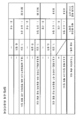
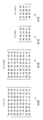
도 19는, H.264/AVC에 있어서 미리 정의되어 있는 4종류의 양자화 행렬의 기정값(디폴트값)을 나타내고 있다. 예를 들어, 인트라 예측 모드에서 변환 단위의 사이즈가 4×4인 경우에는 행렬SL01이 양자화 행렬의 기정값이다. 인터 예측 모드에서 변환 단위의 크기가 4×4인 경우에는 행렬SL02가 양자화 행렬의 기정값이다. 인트라 예측 모드에서 변환 단위의 크기가 8×8인 경우에는 행렬SL03이 양자화 행렬의 기정값이다. 인터 예측 모드에서 변환 단위의 크기가 8×8인 경우에는 행렬SL04가 양자화 행렬의 기정값이다. 또한, 유저는 시퀀스 파라미터 세트 또는 픽처 파라미터 세트에 있어서, 도 19에 나타낸 기정값과는 상이한 독자의 양자화 행렬을 지정할 수 있다. 양자화 행렬이 사용되지 않을 경우에는, 양자화 시에 사용되는 양자화 스텝은 모든 성분에 대하여 동등한 값이 된다.Fig. 19 shows the default values (default values) of the four kinds of quantization matrices defined in advance in H.264 / AVC. For example, when the size of the conversion unit is 4x4 in the intra prediction mode, the matrix SL01 is the default value of the quantization matrix. In the inter prediction mode, when the size of the conversion unit is 4x4, the matrix SL02 is the default value of the quantization matrix. In the intra prediction mode, when the size of the conversion unit is 8x8, the matrix SL03 is the default value of the quantization matrix. In the inter prediction mode, when the size of the conversion unit is 8x8, the matrix SL04 is the default value of the quantization matrix. Further, the user can designate a unique quantization matrix different from the default value shown in Fig. 19 in the sequence parameter set or the picture parameter set. When the quantization matrix is not used, the quantization step used at the time of quantization is equivalent to all components.
H.264/AVC에 이어지는 차세대의 영상 부호화 방식으로서 표준화가 진행되고 있는 HEVC(High Efficiency Video Coding)에서는, 종래의 매크로 블록에 상당하는 부호화 단위(CU: Coding Unit)라고 하는 개념이 도입되어 있다(하기 비특허문헌 1 참조). 부호화 단위 크기의 범위는, 시퀀스 파라미터 세트에 있어서, LCU(Largest Coding Unit) 및 SCU(Smallest Coding Unit)라고 하는 2의 거듭제곱값의 세트로 지정된다. 그리고, split_flag을 사용하여 LCU 및 SCU에서 지정된 범위 내의 구체적인 부호화 단위의 크기가 특정된다.In HEVC (High Efficiency Video Coding), which is being standardized as a next-generation image coding method following H.264 / AVC, a concept called a coding unit (CU) equivalent to a conventional macroblock is introduced Non-patent document 1). The range of the coding unit size is specified by a set of two power values, called LCU (Largest Coding Unit) and SCU (Smallest Coding Unit), in the sequence parameter set. Then, the size of a specific encoding unit within the range specified by the LCU and the SCU is specified using the split_flag.
HEVC에서는, 1개의 부호화 단위는 1개 이상의 직교 변환의 단위, 즉 1개 이상의 변환 단위(Transform Unit: TU)로 분할될 수 있다. 변환 단위의 크기로는 4×4, 8×8, 16×16 및 32×32 중 어느 하나가 이용 가능하다. 따라서, 양자화 행렬도 또한, 이들 변환 단위의 후보 크기마다 지정될 수 있다.In the HEVC, one coding unit can be divided into one or more orthogonal transformation units, that is, one or more transformation units (TUs). As the size of the conversion unit, any one of 4x4, 8x8, 16x16, and 32x32 is available. Therefore, the quantization matrix can also be specified for each candidate size of these conversion units.
그런데, H.264/AVC에서는, JM(Joint Model)이라고 불리는 공개된 참조 소프트웨어(http://iphome.hhi.de/suehring/tml/index.htm)에 있어서 사양화되어 있는 바와 같이, 1픽처 내에서 하나의 변환 단위의 크기에 대해서 하나의 양자화 행렬만을 지정하는 것이 가능하였다. 이에 비해, 하기 비특허문헌 2는, 1픽처 내에서 하나의 변환 단위의 크기에 대하여 복수의 양자화 행렬의 후보를 지정하고, RD(Rate-Distortion)의 최적화의 관점에서 블록마다 적절하게 양자화 행렬을 선택하는 것을 제안하고 있다.By the way, in H.264 / AVC, as specified in published reference software (http://iphome.hhi.de/suehring/tml/index.htm) called JM (Joint Model) It is possible to designate only one quantization matrix for the size of one conversion unit. On the other hand, the following
그러나, 선택 가능한 변환 단위 크기의 종류가 많아지면, 대응하는 양자화 행렬의 수도 증가하고, 양자화 행렬의 부호량의 증가가 부호화 효율의 저하를 초래할 수 있다. 또한, 이러한 부호화 효율의 저하는, 변환 단위의 크기마다 지정 가능한 양자화 행렬의 수가 1개에서 복수가 되면, 보다 현저해질 우려도 있다.However, if the number of types of selectable conversion unit sizes increases, the number of corresponding quantization matrices also increases, and an increase in the code amount of the quantization matrix may cause a decrease in coding efficiency. This degradation of the coding efficiency may be more remarkable when the number of quantization matrices that can be specified for each size of the conversion unit becomes one to plural.
따라서, 본 개시에 관한 기술은, 양자화 행렬의 수가 많아지는 경우의 부호량의 증가를 억제할 수 있는 화상 처리 장치 및 화상 처리 방법을 제공하려고 하는 것이다.Therefore, the technology of the present disclosure is intended to provide an image processing apparatus and an image processing method capable of suppressing an increase in the code amount when the number of quantization matrices is increased.
어떤 실시 형태에 따르면, 크기가 상이한 복수의 변환 단위로부터, 복호되는 화상 데이터의 역직교 변환을 위하여 사용되는 변환 단위를 선택하는 선택부와, 제1 크기의 변환 단위에 대응하는 제1 양자화 행렬로부터, 제2 크기의 변환 단위에 대응하는 제2 양자화 행렬을 생성하는 생성부와, 상기 선택부에 의해 상기 제2 크기의 변환 단위가 선택된 경우에, 상기 생성부에 의해 생성된 상기 제2 양자화 행렬을 사용하여 상기 화상 데이터의 변환 계수 데이터를 역양자화하는 역양자화부를 구비하는 화상 처리 장치가 제공된다.According to an embodiment, there is provided an image processing apparatus including: a selection unit that selects, from a plurality of conversion units having different sizes, a conversion unit used for inverse orthogonal conversion of image data to be decoded; A generation unit configured to generate a second quantization matrix corresponding to a conversion unit of a second size when the conversion unit of the second size is selected by the selection unit; And an inverse quantization unit for inversely quantizing the transform coefficient data of the image data using the inverse quantization unit.
상기 화상 처리 장치는 전형적으로는 화상을 복호하는 화상 복호 장치로서 실현될 수 있다.The image processing apparatus is typically realized as an image decoding apparatus for decoding an image.
또한, 상기 생성부는, 상기 제1 양자화 행렬을 특정하는 행렬 정보, 및 상기 제1 양자화 행렬로부터 예측되는 상기 제2 크기의 예측 행렬과 상기 제2 양자화 행렬의 차분을 나타내는 차분 정보를 사용하여 상기 제2 양자화 행렬을 생성해도 된다.The generating unit may generate the quantization matrix using the matrix information for specifying the first quantization matrix and the difference information indicating the difference between the prediction matrix of the second size predicted from the first quantization matrix and the second quantization matrix, 2 quantization matrix may be generated.
또한, 상기 생성부는, 시퀀스 파라미터 세트 또는 픽처 파라미터 세트로부터 상기 행렬 정보 및 상기 차분 정보를 취득해도 된다.The generation unit may acquire the matrix information and the difference information from a sequence parameter set or a picture parameter set.
또한, 상기 생성부는, 상기 예측 행렬과 상기 제2 양자화 행렬의 차분이 존재하지 않는 것을 나타내는 제1 플래그가 시퀀스 파라미터 세트 또는 픽처 파라미터 세트로부터 취득된 경우에는 상기 예측 행렬을 상기 제2 양자화 행렬로 해도 된다.When the first flag indicating that the difference between the prediction matrix and the second quantization matrix does not exist is obtained from the sequence parameter set or the picture parameter set, the generation unit may generate the second quantization matrix as the second quantization matrix do.
또한, 상기 제1 크기는 상기 복수의 변환 단위의 크기 중 최소의 크기이어도 된다.The first size may be a minimum size of the plurality of conversion units.
또한, 상기 제2 크기는 상기 제1 크기보다도 크고, 상기 생성부는 상기 제1 양자화 행렬에 있어서 서로 인접하는 제1 요소와 제2 요소의 사이의 요소로서 상기 제1 요소 또는 상기 제2 요소를 복제함으로써 상기 예측 행렬을 산출해도 된다.The second size is larger than the first size, and the generation unit is configured to replicate the first element or the second element as an element between the first element and the second element adjacent to each other in the first quantization matrix. The prediction matrix may be calculated.
또한, 상기 제2 크기는 상기 제1 크기보다도 크고, 상기 생성부는 상기 제1 양자화 행렬에 있어서 서로 인접하는 제1 요소와 제2 요소의 사이의 요소를 선형 보간함으로써 상기 예측 행렬을 산출해도 된다.Also, the second size may be larger than the first size, and the generation unit may calculate the prediction matrix by linearly interpolating elements between the first element and the second element adjacent to each other in the first quantization matrix.
또한, 상기 제2 크기는 한 변에 있어서 상기 제1 크기의 2배이어도 된다.The second size may be twice the first size on one side.
또한, 상기 제2 크기는 상기 제1 크기보다도 작고, 상기 생성부는 상기 제1 양자화 행렬의 요소를 씨닝함으로써 상기 예측 행렬을 산출해도 된다.Also, the second size may be smaller than the first size, and the generation unit may calculate the prediction matrix by thinning the elements of the first quantization matrix.
또한, 상기 제2 크기는 상기 제1 크기보다도 작고, 상기 생성부는 상기 제1 양자화 행렬에 있어서 서로 인접하는 복수의 요소의 평균을 계산함으로써 상기 예측 행렬을 산출해도 된다.Also, the second size may be smaller than the first size, and the generation unit may calculate the prediction matrix by calculating an average of a plurality of elements adjacent to each other in the first quantization matrix.
또한, 상기 생성부는, 상기 제2 양자화 행렬에 대하여 유저에 의해 정의된 행렬의 사용을 지정하는 제2 플래그가 시퀀스 파라미터 세트 또는 픽처 파라미터 세트로부터 취득된 경우에 상기 제1 양자화 행렬로부터 상기 제2 양자화 행렬을 생성해도 된다.The generating unit may further include a second quantization unit that, when a second flag designating use of a matrix defined by the user for the second quantization matrix is acquired from a sequence parameter set or a picture parameter set, A matrix may be generated.
또한, 다른 실시 형태에 따르면, 크기가 상이한 복수의 변환 단위로부터, 복호되는 화상 데이터의 역직교 변환을 위하여 사용되는 변환 단위를 선택하는 것과, 제1 크기의 변환 단위에 대응하는 제1 양자화 행렬로부터, 제2 크기의 변환 단위에 대응하는 제2 양자화 행렬을 생성하는 것과, 상기 제2 크기의 변환 단위가 선택된 경우에 상기 제1 양자화 행렬로부터 생성된 상기 제2 양자화 행렬을 사용하여 상기 화상 데이터의 변환 계수 데이터를 역양자화하는 것을 포함하는 화상 처리 방법이 제공된다.According to another embodiment, it is possible to select a conversion unit to be used for inverse orthogonal transformation of image data to be decoded from a plurality of conversion units of different sizes, and to select a conversion unit to be used for inverse orthogonal transformation from the first quantization matrix corresponding to the conversion unit of the first size And generating a second quantization matrix corresponding to the second size conversion unit by using the second quantization matrix generated from the first quantization matrix when the conversion unit of the second size is selected, An image processing method is provided that includes dequantizing transform coefficient data.
또한, 다른 실시 형태에 따르면, 크기가 상이한 복수의 변환 단위로부터, 부호화되는 화상 데이터의 직교 변환을 위하여 사용되는 변환 단위를 선택하는 선택부와, 상기 선택부에 의해 선택된 변환 단위로 상기 화상 데이터를 직교 변환함으로써 생성된 변환 계수 데이터를, 상기 선택된 변환 단위에 대응하는 양자화 행렬을 사용하여 양자화하는 양자화부와, 제1 크기의 변환 단위에 대응하는 제1 양자화 행렬로부터 제2 크기의 변환 단위에 대응하는 제2 양자화 행렬을 생성하기 위한 정보를 부호화하는 부호화부를 구비하는 화상 처리 장치가 제공된다.According to another aspect of the present invention, there is provided an image processing apparatus including: a selection unit that selects, from a plurality of conversion units having different sizes, a conversion unit used for orthogonal conversion of image data to be encoded; A quantization unit for quantizing the transform coefficient data generated by the orthogonal transform using the quantization matrix corresponding to the selected transform unit, and a transform unit for transforming the transform coefficient data from the first quantization matrix corresponding to the first- And a coding unit for coding information for generating a second quantization matrix to be coded.
상기 화상 처리 장치는 전형적으로는 화상을 부호화하는 화상 부호화 장치로서 실현될 수 있다.The image processing apparatus is typically realized as a picture coding apparatus for coding an image.
또한, 다른 실시 형태에 따르면, 크기가 상이한 복수의 변환 단위로부터, 부호화되는 화상 데이터의 직교 변환을 위하여 사용되는 변환 단위를 선택하는 것과, 선택된 변환 단위로 상기 화상 데이터를 직교 변환함으로써 생성된 변환 계수 데이터를, 상기 선택된 변환 단위에 대응하는 양자화 행렬을 사용하여 양자화하는 것과, 제1 크기의 변환 단위에 대응하는 제1 양자화 행렬로부터 제2 크기의 변환 단위에 대응하는 제2 양자화 행렬을 생성하기 위한 정보를 부호화하는 것을 포함하는 화상 처리 방법이 제공된다.According to another aspect of the present invention, there is provided an image processing method comprising: selecting a conversion unit to be used for orthogonal conversion of image data to be encoded from a plurality of conversion units having different sizes; A quantization step of quantizing the data by using a quantization matrix corresponding to the selected conversion unit and generating a second quantization matrix corresponding to a conversion unit of a second size from the first quantization matrix corresponding to the conversion unit of the first size There is provided an image processing method including encoding information.
이상 설명한 바와 같이, 본 개시에 관한 화상 처리 장치 및 화상 처리 방법에 의하면, 양자화 행렬의 수가 많아지는 경우의 부호량의 증가를 억제할 수 있다.As described above, according to the image processing apparatus and the image processing method of the present disclosure, it is possible to suppress an increase in the code amount when the number of quantization matrices increases.
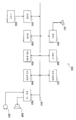
도 1은 일실시 형태에 관한 화상 부호화 장치의 구성의 일례를 나타내는 블록도이다.
도 2는 일실시 형태에 관한 직교 변환·양자화부의 상세한 구성의 일례를 나타내는 블록도이다.
도 3은 일실시 형태에 관한 행렬 처리부의 더욱 상세한 구성의 일례를 나타내는 블록도이다.
도 4는 일실시 형태에 있어서 시퀀스 파라미터 세트 내에 삽입되는 정보의 일례를 나타내는 설명도이다.
도 5는 일실시 형태에 있어서 픽처 파라미터 세트 내에 삽입되는 정보의 일례를 나타내는 설명도이다.
도 6a는 일실시 형태에 관한 부호화시의 처리 흐름의 제1 예를 나타내는 흐름도의 전반부이다.
도 6b는 일실시 형태에 관한 부호화시의 처리 흐름의 제1 예를 나타내는 흐름도의 후반부이다.
도 7a는 일실시 형태에 관한 부호화시의 처리 흐름의 제2 예를 나타내는 흐름도의 전반부이다.
도 7b는 일실시 형태에 관한 부호화시의 처리 흐름의 제2 예를 나타내는 흐름도의 후반부이다.
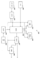
도 8은 일실시 형태에 관한 화상 복호 장치의 구성의 일례를 나타내는 블록도이다.
도 9는 일실시 형태에 관한 역양자화·역직교 변환부의 상세한 구성의 일례를 나타내는 블록도이다.
도 10은 일실시 형태에 관한 행렬 생성부의 더욱 상세한 구성의 일례를 나타내는 블록도이다.
도 11a는 일실시 형태에 관한 복호시의 처리 흐름의 제1 예를 나타내는 흐름도의 전반부이다.
도 11b는 일실시 형태에 관한 복호시의 처리 흐름의 제1 예를 나타내는 흐름도의 후반부이다.
도 12a는 일실시 형태에 관한 복호시의 처리 흐름의 제2 예를 나타내는 흐름도의 전반부이다.
도 12b는 일실시 형태에 관한 복호시의 처리 흐름의 제2 예를 나타내는 흐름도의 후반부이다.
도 13a는 하나의 변형예에 관한 부호화시의 처리 흐름의 일례를 나타내는 흐름도의 전반부이다.
도 13b는 하나의 변형예에 관한 부호화시의 처리 흐름의 일례를 나타내는 흐름도의 후반부이다.
도 14a는 하나의 변형예에 관한 복호시의 처리 흐름의 일례를 나타내는 흐름도의 전반부이다.
도 14b는 하나의 변형예에 관한 복호시의 처리 흐름의 일례를 나타내는 흐름도의 후반부이다.
도 15는 텔레비전 장치의 개략적인 구성의 일례를 나타내는 블록도이다.
도 16은 휴대 전화기의 개략적인 구성의 일례를 나타내는 블록도이다.
도 17은 기록 재생 장치의 개략적인 구성의 일례를 나타내는 블록도이다.
도 18은 촬상 장치의 개략적인 구성의 일례를 나타내는 블록도이다.
도 19는 H.264/AVC에 있어서 미리 정의되어 있는 양자화 행렬의 기정값을 나타내는 설명도이다.1 is a block diagram showing an example of a configuration of a picture coding apparatus according to an embodiment.
2 is a block diagram showing an example of a detailed configuration of an orthogonal transformation / quantization unit according to an embodiment;
3 is a block diagram showing an example of a more detailed configuration of the matrix processing unit according to the embodiment.
4 is an explanatory diagram showing an example of information inserted in a sequence parameter set in one embodiment;
5 is an explanatory diagram showing an example of information inserted in a picture parameter set in one embodiment.
6A is a first half of a flowchart showing a first example of a process flow in encoding according to an embodiment.
FIG. 6B is a second half of the flowchart showing a first example of the processing flow at the time of encoding according to the embodiment.
FIG. 7A is a first part of a flowchart showing a second example of the processing flow at the time of encoding according to the embodiment.
FIG. 7B is a second half of the flowchart showing a second example of the processing flow at the time of encoding according to the embodiment.
8 is a block diagram showing an example of the configuration of the image decoding apparatus according to the embodiment.
9 is a block diagram showing an example of a detailed configuration of an inverse quantization / inverse orthogonal transformation unit according to an embodiment.
10 is a block diagram showing an example of a more detailed configuration of the matrix generation unit according to the embodiment.
11A is a first half of a flowchart showing a first example of a process flow at the time of decoding according to the embodiment.
11B is a second half of a flowchart showing a first example of the processing flow at the time of decoding according to the embodiment.
12A is a first half of a flowchart showing a second example of a process flow at the time of decoding according to the embodiment.
12B is a second half of the flowchart showing a second example of the processing flow at the time of decoding according to the embodiment.
13A is a first half of a flowchart showing an example of a process flow at the time of encoding according to one modification.
FIG. 13B is a second half of the flowchart showing an example of the processing flow at the time of encoding according to one modified example.
14A is a first part of a flowchart showing an example of a processing flow at the time of decoding according to one modified example.
14B is a second half of the flowchart showing an example of the processing flow at the time of decoding according to one modified example.
15 is a block diagram showing an example of a schematic configuration of a television apparatus.
16 is a block diagram showing an example of a schematic configuration of a cellular phone.
17 is a block diagram showing an example of a schematic configuration of a recording and reproducing apparatus.
18 is a block diagram showing an example of a schematic configuration of an image pickup apparatus.
Fig. 19 is an explanatory diagram showing a predetermined value of a quantization matrix predefined in H.264 / AVC; Fig.
이하에 첨부 도면을 참조하면서 본 개시가 적합한 실시 형태에 대하여 상세하게 설명한다. 또한, 본 명세서 및 도면에 있어서, 실질적으로 동일한 기능 구성을 갖는 구성 요소에 대해서는 동일한 부호를 부여함으로써 중복 설명을 생략한다.BEST MODE FOR CARRYING OUT THE INVENTION Hereinafter, preferred embodiments of the present disclosure will be described in detail with reference to the accompanying drawings. Note that, in the present specification and drawings, constituent elements having substantially the same functional configuration are denoted by the same reference numerals, and redundant description will be omitted.
또한, 이하의 순서에 따라서 당해 「발명을 실시하기 위한 형태」를 설명한다.In addition, the form for carrying out the invention will be described in the following order.
1. 일실시 형태에 관한 화상 부호화 장치의 구성예1. Configuration Example of Picture Coding Apparatus According to Embodiment
1-1. 전체적인 구성예1-1. Overall configuration example
1-2. 직교 변환·양자화부의 구성예1-2. Examples of orthogonal transformation and quantization unit
1-3. 행렬 처리부의 상세한 구성예1-3. Detailed Configuration Example of Matrix Processing Unit
1-4. 부호화되는 정보의 예1-4. Examples of information to be encoded
2. 일실시 형태에 관한 부호화시의 처리 흐름2. Processing Flow at the Time of Encoding in One Embodiment
3. 일실시 형태에 관한 화상 복호 장치의 구성예3. Configuration Example of Image Decoding Apparatus According to One Embodiment
3-1. 전체적인 구성예3-1. Overall configuration example
3-2. 역양자화·역직교 변환부의 구성예3-2. Example of configuration of inverse quantization and inverse orthogonal transform unit
3-3. 행렬 생성부의 상세한 구성예3-3. Detailed Configuration Example of Matrix Generator
4. 일실시 형태에 관한 복호시의 처리 흐름4. Process Flow in Decoding in One Embodiment
5. 변형예5. Modifications
6. 응용예6. Application Examples
7. 정리7. Theorem
<1. 일실시 형태에 관한 화상 부호화 장치의 구성예><1. Configuration Example of Picture Coding Apparatus According to One Embodiment>
본 절에서는 일실시 형태에 관한 화상 부호화 장치의 구성예에 대하여 설명한다.In this section, a configuration example of the picture coding apparatus according to one embodiment will be described.
[1-1. 전체적인 구성예][1-1. Overall configuration example]
도 1은 일실시 형태에 관한 화상 부호화 장치(10)의 구성의 일례를 나타내는 블록도이다. 도 1을 참조하면, 화상 부호화 장치(10)는 A/D(Analogue to Digital) 변환부(11), 재배열 버퍼(12), 감산부(13), 직교 변환·양자화부(14), 가역 부호화부(16), 축적 버퍼(17), 레이트 제어부(18), 역양자화부(21), 역직교 변환부(22), 가산부(23), 디블록 필터(24), 프레임 메모리(25), 셀렉터(26), 인트라 예측부(30), 움직임 탐색부(40) 및 모드 선택부(50)를 구비한다.1 is a block diagram showing an example of the configuration of a
A/D 변환부(11)는 아날로그 형식으로 입력되는 화상 신호를 디지털 형식의 화상 데이터로 변환하고, 일련의 디지털 화상 데이터를 재배열 버퍼(12)로 출력한다.The A /
재배열 버퍼(12)는 A/D 변환부(11)로부터 입력되는 일련의 화상 데이터에 포함되는 화상을 재배열한다. 재배열 버퍼(12)는, 부호화 처리에 관한 GOP(Group of Pictures) 구조에 따라서 화상을 재배열한 후, 재배열 후의 화상 데이터를 감산부(13), 인트라 예측부(30) 및 움직임 탐색부(40)로 출력한다.The
감산부(13)에는, 재배열 버퍼(12)로부터 입력되는 화상 데이터, 및 나중에 설명하는 모드 선택부(50)에 의해 선택되는 예측 화상 데이터가 공급된다. 감산부(13)는, 재배열 버퍼(12)로부터 입력되는 화상 데이터와 모드 선택부(50)로부터 입력되는 예측 화상 데이터의 차분인 예측 오차 데이터를 산출하고, 산출한 예측 오차 데이터를 직교 변환·양자화부(14)로 출력한다.Image data input from the
직교 변환·양자화부(14)는, 감산부(13)로부터 입력되는 예측 오차 데이터에 대하여 직교 변환 및 양자화를 행하고, 양자화된 변환 계수 데이터(이하, 양자화 데이터라고 함)를 가역 부호화부(16) 및 역양자화부(21)로 출력한다. 직교 변환·양자화부(14)로부터 출력되는 양자화 데이터의 비트 레이트는, 레이트 제어부(18)로부터의 레이트 제어 신호에 기초하여 제어된다. 직교 변환·양자화부(14)의 상세한 구성에 대해서 나중에 다시 설명한다.The orthogonal transformation /
가역 부호화부(16)에는, 직교 변환·양자화부(14)로부터 입력되는 양자화 데이터 및 복호측에서 양자화 행렬을 생성하기 위한 정보, 및 , 모드 선택부(50)에 의해 선택되는 인트라 예측 또는 인터 예측에 관한 정보가 공급된다. 인트라 예측에 관한 정보는, 예를 들어 블록마다 최적인 인트라 예측 모드를 나타내는 예측 모드 정보를 포함할 수 있다. 또한, 인터 예측에 관한 정보는, 예를 들어 블록마다의 움직임 벡터의 예측을 위한 예측 모드 정보, 차분 움직임 벡터 정보 및 참조 화상 정보 등을 포함할 수 있다.The
가역 부호화부(16)는, 양자화 데이터에 대하여 가역 부호화 처리를 행함으로써 부호화 스트림을 생성한다. 가역 부호화부(16)에 의한 가역 부호화는, 예를 들어 가변장 부호화, 또는 산술 부호화 등이어도 된다. 또한, 가역 부호화부(16)는, 상세하게 후술하는 양자화 행렬을 생성하기 위한 정보를, 부호화 스트림의 헤더(예를 들어, 시퀀스 파라미터 세트 및 픽처 파라미터 세트) 내에 다중화한다. 또한, 가역 부호화부(16)는, 상술한 인트라 예측에 관한 정보 또는 인터 예측에 관한 정보를 부호화 스트림의 헤더 내에 다중화한다. 그리고, 가역 부호화부(16)는 생성한 부호화 스트림을 축적 버퍼(17)로 출력한다.The
축적 버퍼(17)는, 가역 부호화부(16)로부터 입력되는 부호화 스트림을 반도체 메모리 등의 기억 매체를 사용하여 일시적으로 축적한다. 그리고, 축적 버퍼(17)는, 축적한 부호화 스트림을 전송로(또는 화상 부호화 장치(10)로부터의 출력선)의 대역에 따른 레이트로 출력한다.The
레이트 제어부(18)는 축적 버퍼(17)의 빈 용량을 감시한다. 그리고, 레이트 제어부(18)는, 축적 버퍼(17)의 빈 용량에 따라서 레이트 제어 신호를 생성하고, 생성한 레이트 제어 신호를 직교 변환·양자화부(14)로 출력한다. 예를 들어, 레이트 제어부(18)는, 축적 버퍼(17)의 빈 용량이 적을 때에는 양자화 데이터의 비트 레이트를 저하시키기 위한 레이트 제어 신호를 생성한다. 또한, 예를 들어 레이트 제어부(18)는, 축적 버퍼(17)의 빈 용량이 충분히 클 때에는 양자화 데이터의 비트 레이트를 높이기 위한 레이트 제어 신호를 생성한다.The
역양자화부(21)는 직교 변환·양자화부(14)로부터 입력되는 양자화 데이터에 대하여 역양자화 처리를 행한다. 그리고, 역양자화부(21)는 역양자화 처리에 의해 취득되는 변환 계수 데이터를 역직교 변환부(22)로 출력한다.The
역직교 변환부(22)는, 역양자화부(21)로부터 입력되는 변환 계수 데이터에 대하여 역직교 변환 처리를 행함으로써 예측 오차 데이터를 복원한다. 그리고, 역직교 변환부(22)는 복원한 예측 오차 데이터를 가산부(23)로 출력한다.The inverse
가산부(23)는, 역직교 변환부(22)로부터 입력되는 복원된 예측 오차 데이터와 모드 선택부(50)로부터 입력되는 예측 화상 데이터를 가산함으로써 복호 화상 데이터를 생성한다. 그리고, 가산부(23)는, 생성한 복호 화상 데이터를 디블록 필터(24) 및 프레임 메모리(25)로 출력한다.The
디블록 필터(24)는, 화상의 부호화시에 발생하는 블록 왜곡을 감소시키기 위한 필터링 처리를 행한다. 디블록 필터(24)는, 가산부(23)로부터 입력되는 복호 화상 데이터를 필터링함으로써 블록 왜곡을 제거하고, 필터링 후의 복호 화상 데이터를 프레임 메모리(25)로 출력한다.The
프레임 메모리(25)는, 가산부(23)로부터 입력되는 복호 화상 데이터 및 디블록 필터(24)로부터 입력되는 필터링 후의 복호 화상 데이터를 기억 매체를 사용하여 기억한다.The
셀렉터(26)는, 인트라 예측을 위하여 사용되는 필터링 전의 복호 화상 데이터를 프레임 메모리(25)로부터 판독하고, 판독한 복호 화상 데이터를 참조 화상 데이터로서 인트라 예측부(30)에 공급한다. 또한, 셀렉터(26)는, 인터 예측을 위하여 사용되는 필터링 후의 복호 화상 데이터를 프레임 메모리(25)로부터 판독하고, 판독한 복호 화상 데이터를 참조 화상 데이터로서 움직임 탐색부(40)에 공급한다.The
인트라 예측부(30)는, 재배열 버퍼(12)로부터 입력되는 부호화 대상의 화상 데이터 및 셀렉터(26)를 통하여 공급되는 복호 화상 데이터에 기초하여 각 인트라 예측 모드의 인트라 예측 처리를 행한다. 예를 들어, 인트라 예측부(30)는 각 인트라 예측 모드에 의한 예측 결과를 소정의 비용 함수를 사용하여 평가한다. 그리고, 인트라 예측부(30)는, 비용 함수값이 최소가 되는 인트라 예측 모드, 즉 압축률이 가장 높아지는 인트라 예측 모드를 최적인 인트라 예측 모드로서 선택한다. 또한, 인트라 예측부(30)는, 당해 최적의 인트라 예측 모드를 나타내는 예측 모드 정보, 예측 화상 데이터 및 비용 함수값 등의 인트라 예측에 관한 정보를 모드 선택부(50)로 출력한다.The
움직임 탐색부(40)는, 재배열 버퍼(12)로부터 입력되는 부호화 대상의 화상 데이터 및 셀렉터(26)를 통하여 공급되는 복호 화상 데이터에 기초하여 인터 예측 처리(프레임간 예측 처리)를 행한다. 예를 들어, 움직임 탐색부(40)는 각 예측 모드에 의한 예측 결과를 소정의 비용 함수를 사용하여 평가한다. 이어서, 움직임 탐색부(40)는, 비용 함수값이 최소가 되는 예측 모드, 즉 압축률이 가장 높아지는 예측 모드를 최적인 예측 모드로서 선택한다. 또한, 움직임 탐색부(40)는 당해 최적의 예측 모드에 따라서 예측 화상 데이터를 생성한다. 그리고, 움직임 탐색부(40)는, 선택한 최적인 예측 모드를 나타내는 예측 모드 정보를 포함하는 인터 예측에 관한 정보, 예측 화상 데이터 및 비용 함수값 등의 인터 예측에 관한 정보를 모드 선택부(50)로 출력한다.The
모드 선택부(50)는, 인트라 예측부(30)로부터 입력되는 인트라 예측에 관한 비용 함수값과 움직임 탐색부(40)로부터 입력되는 인터 예측에 관한 비용 함수값을 비교한다. 그리고, 모드 선택부(50)는 인트라 예측 및 인터 예측 중 비용 함수값이 보다 적은 예측 방법을 선택한다. 모드 선택부(50)는, 인트라 예측을 선택한 경우에는 인트라 예측에 관한 정보를 가역 부호화부(16)로 출력함과 함께, 예측 화상 데이터를 감산부(13) 및 가산부(23)로 출력한다. 또한, 모드 선택부(50)는, 인터 예측을 선택한 경우에는, 인터 예측에 관한 상술한 정보를 가역 부호화부(16)로 출력함과 함께, 예측 화상 데이터를 감산부(13) 및 가산부(23)로 출력한다.The
[1-2. 직교 변환·양자화부의 구성예][1-2. Configuration example of orthogonal transformation / quantization unit]
도 2는 도 1에 도시한 화상 부호화 장치(10)의 직교 변환·양자화부(14)의 상세한 구성의 일례를 나타내는 블록도이다. 도 2를 참조하면, 직교 변환·양자화부(14)는 선택부(110), 직교 변환부(120), 양자화부(130), 양자화 행렬 버퍼(140) 및 행렬 처리부(15)를 갖는다.2 is a block diagram showing an example of a detailed configuration of the orthogonal transformation /
(1)선택부(1)
선택부(110)는, 크기가 상이한 복수의 변환 단위로부터, 부호화되는 화상 데이터의 직교 변환을 위하여 사용되는 변환 단위(TU)를 선택한다. 선택부(110)에 의해 선택될 수 있는 변환 단위 크기의 후보는, 예를 들어 H.264/AVC에서는 4×4 및 8×8을 포함하고, HEVC에서는 4×4, 8×8, 16×16 및 32×32를 포함한다. 선택부(110)는, 예를 들어 부호화되는 화상의 크기 또는 화질, 또는 장치의 성능 등에 따라서 어느 한쪽의 변환 단위를 선택해도 된다. 선택부(110)에 의한 변환 단위의 선택은 장치를 개발하는 유저에 의해 핸드 튜닝되어도 된다. 그리고, 선택부(110)는, 선택한 변환 단위의 크기를 지정하는 정보를 직교 변환부(120), 양자화부(130), 가역 부호화부(16) 및 역양자화부(21)로 출력한다.The
(2)직교 변환부(2)
직교 변환부(120)는, 선택부(110)에 의해 선택된 변환 단위로, 감산부(13)로부터 공급되는 화상 데이터(즉, 예측 오차 데이터)를 직교 변환한다. 직교 변환부(120)에 의해 실행되는 직교 변환은, 예를 들어 이산 코사인 변환(Discrete Cosine Transform: DCT) 또는 카루넨 루베 변환 등이어도 된다. 그리고, 직교 변환부(120)는 직교 변환 처리에 의해 취득되는 변환 계수 데이터를 양자화부(130)로 출력한다.The
(3)양자화부(3)
양자화부(130)는, 선택부(110)에 의해 선택된 변환 단위에 대응하는 양자화 행렬을 사용하여 직교 변환부(120)에 의해 생성된 변환 계수 데이터를 양자화한다. 또한, 양자화부(130)는, 레이트 제어부(18)로부터의 레이트 제어 신호에 기초하여 양자화 스텝을 전환함으로써 출력되는 양자화 데이터의 비트 레이트를 변화시킨다.The
또한, 양자화부(130)는, 선택부(110)에 의해 선택될 수 있는 복수의 변환 단위에 각각 대응하는 양자화 행렬의 세트를 양자화 행렬 버퍼(140)에 기억시킨다. 예를 들어, HEVC와 같이 4×4, 8×8, 16×16 및 32×32이라는 4종류의 크기의 변환 단위의 후보가 존재하는 경우에는, 이들 4종류의 크기에 각각 대응하는 4종류의 양자화 행렬의 세트가 양자화 행렬 버퍼(140)에 의해 기억될 수 있다. 또한, 어떤 크기에 대하여 도 19에 예시한 바와 같은 미리 정해진 양자화 행렬이 사용될 경우에는, 미리 정해진 양자화 행렬이 사용되는 것(유저에 의해 정의된 양자화 행렬을 사용하지 않는 것)을 나타내는 플래그만이 당해 크기와 관련지어서 양자화 행렬 버퍼(140)에 의해 기억되어도 된다.The
양자화부(130)에 의해 사용될 가능성이 있는 양자화 행렬의 세트는 전형적으로는 부호화 스트림의 시퀀스마다 설정될 수 있다. 또한, 양자화부(130)는 시퀀스마다 설정한 양자화 행렬의 세트를 픽처마다 갱신해도 된다. 이러한 양자화 행렬의 세트의 설정 및 갱신을 제어하기 위한 정보는, 예를 들어 시퀀스 파라미터 세트 및 픽처 파라미터 세트에 삽입될 수 있다.The set of quantization matrices that may be used by the
(4)양자화 행렬 버퍼(4) Quantization matrix buffer
양자화 행렬 버퍼(140)는, 반도체 메모리 등의 기억 매체를 사용하여 선택부(110)에 의해 선택될 수 있는 복수의 변환 단위에 각각 대응하는 양자화 행렬의 세트를 일시적으로 기억한다. 양자화 행렬 버퍼(140)에 의해 기억되는 양자화 행렬의 세트는 다음에 설명하는 행렬 처리부(150)에 의한 처리 시에 참조된다.The
(5)행렬 처리부(5)
행렬 처리부(150)는, 부호화 스트림의 시퀀스마다 및 픽처마다 양자화 행렬 버퍼(140)에 기억되어 있는 양자화 행렬의 세트를 참조하고, 어느 하나의 크기 변환 단위에 대응하는 양자화 행렬로부터 다른 하나 이상의 크기 변환 단위에 대응하는 양자화 행렬을 생성하기 위한 정보를 생성한다. 양자화 행렬 생성의 기초가 되는 변환 단위의 크기는 전형적으로는 복수의 변환 단위의 크기 중 최소의 크기이어도 된다. 즉, HEVC와 같이 4×4, 8×8, 16×16 및 32×32이라는 4종류의 크기 변환 단위의 후보가 존재하는 경우에는, 4×4의 양자화 행렬로부터 다른 크기의 양자화 행렬을 생성하기 위한 정보가 생성될 수 있다. 행렬 처리부(15)에 의해 생성되는 정보는, 예를 들어 나중에 설명하는 기초 행렬 정보 및 차분 행렬 정보를 포함할 수 있다. 그리고, 행렬 처리부(150)에 의해 생성된 정보는 가역 부호화부(16)로 출력되고, 부호화 스트림의 헤더 내에 삽입될 수 있다.The
또한, 본 명세서에서는, 주로 최소 크기의 양자화 행렬로부터 보다 큰 크기의 양자화 행렬이 생성되는 예에 대하여 설명한다. 그러나, 이러한 예에 한정되지 않고, 최소가 아닌 크기의 양자화 행렬로부터, 보다 작은 크기의 양자화 행렬 및/또는 보다 큰 크기의 양자화 행렬이 생성되어도 된다.In the present specification, an example in which a quantization matrix of a larger size is mainly generated from a quantization matrix of a minimum size will be described. However, the present invention is not limited to this example, and a quantization matrix of a smaller size and / or a quantization matrix of a larger size may be generated from a quantization matrix of a non-minimum size.
[1-3. 행렬 처리부의 상세한 구성예][1-3. Detailed Configuration Example of Matrix Processing Unit]
도 3은 도 2에 도시한 직교 변환·양자화부(14)의 행렬 처리부(150)의 더욱 상세한 구성의 일례를 나타내는 블록도이다. 도 3을 참조하면, 행렬 처리부(150)는 예측부(152) 및 차분 연산부(154)를 포함한다.3 is a block diagram showing an example of a more detailed configuration of the
(1)예측부(1)
예측부(152)는, 양자화 행렬 버퍼(140)에 기억되어 있는 양자화 행렬의 세트를 취득하고, 취득한 세트에 포함되는 제1 양자화 행렬로부터 보다 큰 크기의 제2 양자화 행렬을 예측한다. 예를 들어, 4×4의 양자화 행렬(SL1)을 다음과 같이 정의한다:The predicting

예측부(152)에 의해 양자화 행렬(SL1)로부터 예측되는 8×8의 예측 행렬(PSL2)은, 예를 들어 다음의 예측식(2)에 따라 산출될 수 있다:The 8x8 prediction matrix PSL2 predicted from the quantization matrix SL1 by the

예측식(2)를 참조하면, 예측 행렬(PSL2)은, 양자화 행렬(SL1)에 있어서 서로 인접하는 2개의 요소의 사이의 요소로서 당해 2개의 요소 중 어느 하나를 복제함으로써 생성된 행렬이다.Referring to the prediction equation (2), the prediction matrix PSL2 is a matrix generated by replicating any one of the two elements as an element between two elements adjacent to each other in the quantization matrix SL1.
그 대신에, 예측 행렬(PSL2)은 다음 예측식(3)에 따라서 양자화 행렬(SL1)로부터 산출되어도 된다:Instead, the prediction matrix PSL2 may be calculated from the quantization matrix SL1 according to the following prediction equation (3): < EMI ID =

예측식(3)을 참조하면, 예측 행렬(PSL2)은, 양자화 행렬(SL1)에 있어서 서로 인접하는 2개의 요소의 사이의 요소를 당해 2개의 요소로부터 선형 보간함으로써 생성된 행렬이다. 또한, 예측식(3)의 예측 행렬(PSL2)의 우측 단부의 요소는 그 하나 좌측의 요소부터 복제되어 있지만, 그들 우측 단부의 요소는 복제가 아니라 선형 외삽에 의해 산출되어도 된다. 마찬가지로, 예측식(3)의 예측 행렬(PSL2)의 하단부의 요소도 또한, 그 하나 상측의 요소로부터 복제되는 대신에 선형 외삽에 의해 산출되어도 된다. 예를 들어, 예측 행렬(PSL2)의 8행 8열의 성분(PSL28, 8)은 예측식(3)에서는 a33이지만, 선형 외삽에 따라 다음과 같이 산출될 수도 있다:Referring to the prediction equation (3), the prediction matrix PSL2 is a matrix generated by linearly interpolating elements between two adjacent elements in the quantization matrix SL1 from the two elements. The element at the right end of the prediction matrix PSL2 of the prediction equation (3) is copied from the element at the left of the element, but the element at the right end thereof may be calculated by linear extrapolation instead of copying. Likewise, the element at the lower end of the prediction matrix PSL2 of the prediction equation (3) may also be calculated by linear extrapolation instead of being copied from the element at the upper side thereof. For example, the components (PSL2 8 , 8 ) in the eighth row and the eighth row of the prediction matrix PSL2 are a 33 in the prediction equation (3), but may be calculated as follows according to linear extrapolation:
![]()
![]()
예측식(2)는 예측식(3)과 비교하여 적은 계산 비용으로 예측 행렬(PSL2)을 생성할 수 있는 식이다. 한편, 예측식(3)을 이용하면, 보다 본래 사용되는 양자화 행렬에 가까운 매끄러운 예측 행렬을 얻는 것이 가능하다. 따라서, 예측식(3)을 이용하면, 나중에 설명하는 차분 행렬의 각 요소를 0에 가깝게 해서 부호화되는 정보량을 삭감할 수 있다.The prediction equation (2) is an equation that can generate the prediction matrix PSL2 with a small calculation cost as compared with the prediction equation (3). On the other hand, by using the prediction equation (3), it is possible to obtain a smooth prediction matrix close to a quantization matrix originally used. Therefore, by using the prediction equation (3), it is possible to reduce the amount of information encoded with each element of the differential matrix described later close to zero.
또한, 예측식 (2) 및 (3)은 사용 가능한 예측식의 예에 지나지 않고, 다른 임의의 예측식도 또한 사용되어도 된다.The prediction equations (2) and (3) are merely examples of the usable prediction equations, and any other prediction equations may also be used.
예측부(152)는, 양자화 행렬(SL1)로부터 예측 행렬(PSL2)을 생성하면, 생성한 예측 행렬(PSL2)을 차분 연산부(154)로 출력한다. 또한, 예측부(152)는, 예를 들어 양자화 행렬의 세트에 포함되는 8×8의 양자화 행렬(SL2)로부터 16×16의 예측 행렬(PSL3)을 예측하고, 예측 행렬(PSL3)을 차분 연산부(154)로 출력한다. 또한, 예측부(152)는, 양자화 행렬의 세트에 포함되는 16×16의 양자화 행렬(SL3)로부터 32×32의 예측 행렬(PSL4)을 예측하고, 예측 행렬(PSL4)을 차분 연산부(154)로 출력한다. 이들 예측 행렬PSL3 및 예측 행렬PSL4의 예측도 또한, 상술한 예측식 (2) 또는 (3)과 동등한 예측식을 따라서 행해도 된다. 또한, 예측부(152)는, 상술한 예측 행렬(PSL2, PSL3 및 PSL4)의 생성의 기초로 한 4×4의 양자화 행렬(SL1)을 특정하는 기초 행렬 정보를 가역 부호화부(16)로 출력한다.The
(2)차분 연산부(2) Difference operator
차분 연산부(154)는, 예측부(152)로부터 입력되는 예측 행렬(PSL2, PSL3 및 PSL4)과 대응하는 양자화 행렬(SL2, SL3 및 SL4)의 차분을 나타내는 차분 행렬(DSL2, DSL3 및 DSL4)을 수학식 (5) 내지 (7)을 따라서 각각 산출한다:The

그리고, 차분 연산부(154)는 이들 차분 행렬(DSL2, DSL3 및 DSL4)을 나타내는 차분 행렬 정보를 가역 부호화부(16)로 출력한다.Then, the
또한, 행렬 처리부(150)는, 어떤 크기에 대하여 미리 정해진 양자화 행렬이 사용되는 경우에는, 당해 크기의 양자화 행렬의 예측 및 차분 연산을 실행하지 않고, 미리 정해진 양자화 행렬이 사용되는 것을 나타내는 플래그만을 대응하는 크기와 관련지어서 가역 부호화부(16)로 출력한다. 또한, 차분 연산부(154)는, 예측 행렬과 양자화 행렬의 차분이 0인 경우에는, 차분 행렬 정보를 출력하는 대신에 차분이 존재하지 않는 것을 나타내는 플래그만을 가역 부호화부(16)로 출력할 수 있다. 또한, 행렬 처리부(150)는, 픽처 절환의 타이밍에서 양자화 행렬이 갱신되지 않는 경우에는, 양자화 행렬이 갱신되지 않는 것을 나타내는 플래그만을 가역 부호화부(16)로 출력할 수 있다.When a predetermined quantization matrix is used for a certain size, the
[1-4. 부호화되는 정보의 예][1-4. Example of information to be encoded]
(1)시퀀스 파라미터 세트(1) Sequence parameter set
도 4는 본 실시 형태에 있어서 시퀀스 파라미터 세트 내에 삽입되는 정보의 일례를 나타내는 설명도이다. 도 4를 참조하면, 양자화 행렬의 크기(변환 단위(TU)의 크기)마다 부호화되는 정보로서 「행렬 종류별 플래그」, 「차분 플래그」 및 「(부호화되는) 행렬 정보」라고 하는 3종류의 정보가 나타나 있다.4 is an explanatory diagram showing an example of information inserted in the sequence parameter set in the present embodiment. Referring to FIG. 4, three types of information, i.e., "flag for each matrix type", "differential flag", and "(encoded) matrix information" are coded for each size of the quantization matrix Is shown.
행렬 종류별 플래그는, 각 크기에 대해서 유저에 의해 정의되는 양자화 행렬 및 미리 정해진 양자화 행렬 중 어느 것이 사용될지를 지정하는 플래그이다. 어떤 크기에 대하여 행렬 종류별 플래그가 「1」이면, 그 크기의 양자화 행렬은 유저에 의해 정의된다. 또한, 어떤 크기에 대하여 행렬 종류별 플래그가 「0」이면, 그 크기의 양자화 행렬은 미리 정해진 양자화 행렬이다. 행렬 종류별 플래그가 「0」인 경우, 행렬 정보 및 차분 행렬 정보 및 다음에 설명하는 차분 플래그는 모두 부호화되지 않는다.The flag for each matrix type is a flag for specifying which of a quantization matrix defined by the user and a predetermined quantization matrix is used for each size. If the flag for each matrix type is " 1 " for a certain size, the quantization matrix of that size is defined by the user. If the flag for each matrix type is " 0 " for a certain size, the quantization matrix of that size is a predetermined quantization matrix. When the flag for each matrix type is " 0 ", neither the matrix information nor the differential matrix information nor the differential flag described below is encoded.
차분 플래그는, 각 크기에 대해서 행렬 종류별 플래그가 「1:유저 정의」인 경우에 예측 행렬과 양자화 행렬의 차분이 존재하는지 여부를 나타내는 플래그이다. 어떤 크기에 대하여 차분 플래그가 「1」이면, 그 크기의 예측 행렬과 양자화 행렬의 차분이 존재하고, 차분 행렬 정보가 부호화된다. 어떤 크기에 대하여 차분 플래그가 「0」이면, 그 크기의 차분 행렬 정보는 부호화되지 않는다. 또한, 예측의 기초가 되는 크기(예를 들어 4×4)에 대해서는 행렬 종류별 플래그에 의하지 않고 차분 플래그는 부호화되지 않는다.The difference flag is a flag indicating whether there is a difference between the prediction matrix and the quantization matrix when the flag for each matrix type is "1: user defined" for each size. If the difference flag is " 1 " for a certain size, there exists a difference between the prediction matrix of the size and the quantization matrix, and the difference matrix information is encoded. If the difference flag is "0" for a certain size, the difference matrix information of the size is not encoded. Further, with respect to the size (for example, 4x4) on which the prediction is based, the difference flag is not encoded without depending on the matrix type flag.
(2)픽처 파라미터 세트(2) a picture parameter set
도 5는 본 실시 형태에 있어서 픽처 파라미터 세트 내에 삽입되는 정보의 일례를 나타내는 설명도이다. 도 5를 참조하면, 양자화 행렬의 크기(변환 단위(TU)의 크기)마다 부호화되는 정보로서 「갱신 플래그」, 「행렬 종류별 플래그」, 「차분 플래그」 및 「(부호화되는) 행렬 정보」라고 하는 4종류의 정보가 나타나 있다. 이 중 행렬 종류별 플래그 및 차분 플래그의 의미는, 도 4를 사용하여 설명한 시퀀스 파라미터 세트의 동일한 명칭의 플래그와 마찬가지이다.5 is an explanatory diagram showing an example of information inserted in a picture parameter set in the present embodiment. Referring to FIG. 5, the information to be coded for each size of the quantization matrix (size of the conversion unit (TU)) is referred to as "update flag", "flag for each matrix type", "differential flag" Four kinds of information are shown. The meanings of the flag for each matrix type and the difference flag are the same as those of the same name in the sequence parameter set described with reference to Fig.
갱신 플래그는 각 크기에 대하여 픽처 절환의 타이밍에서 양자화 행렬을 갱신해야할지 여부를 나타내는 플래그이다. 어떤 크기에 대하여 갱신 플래그가 「1」이면, 그 크기의 양자화 행렬은 갱신된다. 갱신 플래그가 「0」이면, 그 크기의 양자화 행렬은 갱신되지 않고, 앞의 픽처 또는 현재의 시퀀스에 설정된 양자화 행렬이 그대로 사용된다. 갱신 플래그가 「0」인 경우에는, 그 크기에 대하여 행렬 종류별 플래그, 차분 플래그 및 차분 행렬 정보(4×4의 경우에는 행렬 정보)는 부호화되지 않는다.The update flag is a flag indicating whether or not to update the quantization matrix at the timing of picture switching for each size. If the update flag is " 1 " for a certain size, the quantization matrix of the size is updated. If the update flag is " 0 ", the quantization matrix of the size is not updated, and the quantization matrix set in the previous picture or the current sequence is used as it is. When the update flag is " 0 ", the flag for each matrix type, the difference flag, and the difference matrix information (matrix information in the case of 4x4) are not encoded with respect to the size.
<2. 일실시 형태에 관한 부호화시의 처리 흐름><2. Processing Flow at the Time of Coding in One Embodiment>
도 6a 및 도 6b는 본 실시 형태에 관한 부호화시의 처리 흐름의 제1 예를 나타내는 흐름도이다. 당해 흐름도에 나타난 처리는 주로 부호화 스트림의 시퀀스마다 행렬 처리부(150) 및 가역 부호화부(16)에 의해 실행될 수 있다.6A and 6B are flowcharts showing a first example of the processing flow in encoding according to the present embodiment. The processing shown in the flow chart can be executed by the
도 6a를 참조하면, 우선, 행렬 처리부(150)는 당해 시퀀스에 있어서 양자화부(130)에 의해 사용되는 양자화 행렬의 세트를 양자화 행렬 버퍼(140)로부터 취득한다(스텝S100). 여기에서는 일례로서 4×4, 8×8, 16×16 및 32×32의 각 크기에 대응하는 양자화 행렬이 양자화 행렬의 세트에 포함되는 것으로 한다.Referring to FIG. 6A, first, the
이어서, 행렬 처리부(150)는 4×4의 양자화 행렬이 유저에 의해 정의되는 행렬인지 여부를 판정한다(스텝S102). 여기서 4×4의 양자화 행렬이 유저에 의해 정의되는 행렬인 경우에는, 가역 부호화부(16)는 행렬 종류별 플래그(=1) 및 4×4의 양자화 행렬을 나타내는 기초 행렬 정보를 부호화한다(스텝S106). 한편, 4×4의 양자화 행렬이 미리 정해진 행렬인 경우에는, 가역 부호화부(16)는 행렬 종류별 플래그(=0)만을 부호화한다(스텝S108).Subsequently, the
이어서, 행렬 처리부(150)는 8×8의 양자화 행렬이 유저에 의해 정의되는 행렬인지 여부를 판정한다(스텝S112). 여기서 8×8의 양자화 행렬이 유저에 의해 정의되는 행렬인 경우에는, 행렬 처리부(150)는 예를 들어 상술한 예측식 (2) 또는 (3)에 따라 4×4의 양자화 행렬로부터 8×8의 예측 행렬을 산출한다(스텝S114). 그리고, 가역 부호화부(16)는 행렬 종류별 플래그(=1), 차분 플래그 및 8×8의 양자화 행렬과 산출된 예측 행렬의 차분을 나타내는 차분 행렬 정보(차분이 있는 경우만)를 부호화한다(스텝S116). 한편, 8×8의 양자화 행렬이 미리 정해진 행렬인 경우에는, 가역 부호화부(16)는 행렬 종류별 플래그(=0)만을 부호화한다(스텝S118).Subsequently, the
이어서, 도 6b를 참조하면, 행렬 처리부(150)는 16×16의 양자화 행렬이 유저에 의해 정의되는 행렬인지 여부를 판정한다(스텝S122). 여기서 16×16의 양자화 행렬이 유저에 의해 정의되는 행렬인 경우에는, 행렬 처리부(150)는 8×8의 양자화 행렬로부터 16×16의 예측 행렬을 산출한다(스텝S124). 그리고, 가역 부호화부(16)는 행렬 종류별 플래그(=1), 차분 플래그 및 16×16의 양자화 행렬과 산출된 예측 행렬의 차분을 나타내는 차분 행렬 정보(차분이 있는 경우만)를 부호화한다(스텝S126). 한편, 16×16의 양자화 행렬이 미리 정해진 행렬인 경우에는, 가역 부호화부(16)는 행렬 종류별 플래그(=0)만을 부호화한다(스텝S128).Next, referring to FIG. 6B, the
이어서, 행렬 처리부(150)는 32×32의 양자화 행렬이 유저에 의해 정의되는 행렬인지 여부를 판정한다(스텝S132). 여기서 32×32의 양자화 행렬이 유저에 의해 정의되는 행렬인 경우에는, 행렬 처리부(150)는 16×16의 양자화 행렬로부터 32×32의 예측 행렬을 산출한다(스텝S134). 그리고, 가역 부호화부(16)는, 행렬 종류별 플래그(=1), 차분 플래그 및 32×32의 양자화 행렬과 산출된 예측 행렬의 차분을 나타내는 차분 행렬 정보(차분이 있을 경우만)를 부호화한다(스텝S136). 한편, 32×32의 양자화 행렬이 미리 정해진 행렬인 경우에는, 가역 부호화부(16)는 행렬 종류별 플래그(=0)만을 부호화한다(스텝S138).Subsequently, the
도 7a 및 도 7b는 본 실시 형태에 관한 부호화시의 처리 흐름의 제2 예를 나타내는 흐름도이다. 당해 흐름도에 나타난 처리는 주로 부호화 스트림의 픽처마다 행렬 처리부(150) 및 가역 부호화부(16)에 의해 실행될 수 있다.Figs. 7A and 7B are flowcharts showing a second example of the processing flow in encoding according to the present embodiment. Fig. The processing shown in the flow chart can be mainly executed by the
도 7a를 참조하면, 우선, 행렬 처리부(150)는 당해 픽처에 있어서 양자화부(130)에 의해 사용되는 양자화 행렬의 세트를 양자화 행렬 버퍼(140)로부터 취득한다(스텝S150). 여기에서도 도 6a 및 도 6b의 예와 마찬가지로 4×4, 8×8, 16×16 및 32×32의 각 크기에 대응하는 양자화 행렬이 양자화 행렬의 세트에 포함되는 것으로 한다.Referring to FIG. 7A, first, the
이어서, 행렬 처리부(150)는 4×4의 양자화 행렬이 당해 픽처에 있어서 갱신될지 여부를 판정한다(스텝S152). 양자화 행렬이 갱신되지 않을 경우에는, 가역 부호화부(16)는 갱신 플래그(=0)만을 부호화한다(스텝S158). 한편, 양자화 행렬이 갱신될 경우에는, 처리는 스텝S154로 진행한다. 양자화 행렬이 갱신될 경우에는, 행렬 처리부(150)는 새로운 4×4의 양자화 행렬이 유저에 의해 정의되는 행렬인지 여부를 판정한다(스텝S154). 여기서 4×4의 양자화 행렬이 유저에 의해 정의되는 행렬인 경우에는, 가역 부호화부(16)는 갱신 플래그(=1), 행렬 종류별 플래그(=1) 및 4×4의 양자화 행렬을 나타내는 기초 행렬 정보를 부호화한다(스텝S156). 한편, 4×4의 양자화 행렬이 미리 정해진 행렬인 경우에는, 가역 부호화부(16)는 갱신 플래그(=1) 및 행렬 종류별 플래그(=0)를 부호화한다(스텝S158).Subsequently, the
이어서, 행렬 처리부(150)는 8×8의 양자화 행렬이 당해 픽처에 있어서 갱신될지 여부를 판정한다(스텝S160). 양자화 행렬이 갱신되지 않을 경우에는, 가역 부호화부(16)는 갱신 플래그(=0)만을 부호화한다(스텝S168). 한편, 양자화 행렬이 갱신될 경우에는, 처리는 스텝S162로 진행한다. 양자화 행렬이 갱신될 경우에는, 행렬 처리부(150)는 8×8의 양자화 행렬이 유저에 의해 정의되는 행렬인지 여부를 판정한다(스텝S162). 여기서 8×8의 양자화 행렬이 유저에 의해 정의되는 행렬인 경우에는, 행렬 처리부(150)는 4×4의 양자화 행렬이 갱신되었는지 여부에 의하지 않고, 새로운 픽처의 4×4의 양자화 행렬로부터 8×8의 예측 행렬을 산출한다(스텝S164). 그리고, 가역 부호화부(16)는 갱신 플래그(=1), 행렬 종류별 플래그(=1), 차분 플래그 및 8×8의 양자화 행렬과 산출된 예측 행렬의 차분을 나타내는 차분 행렬 정보(차분이 있는 경우만)를 부호화한다(스텝S166). 한편, 8×8의 양자화 행렬이 미리 정해진 행렬인 경우에는, 가역 부호화부(16)는 갱신 플래그(=1) 및 행렬 종류별 플래그(=0)를 부호화한다(스텝S168).Subsequently, the
이어서, 도 7b을 참조하면, 행렬 처리부(150)는 16×16의 양자화 행렬이 당해 픽처에 있어서 갱신될지 여부를 판정한다(스텝S170). 양자화 행렬이 갱신되지 않을 경우에는, 가역 부호화부(16)는 갱신 플래그(=0)만을 부호화한다(스텝S178). 한편, 양자화 행렬이 갱신될 경우에는, 처리는 스텝S172로 진행한다. 양자화 행렬이 갱신될 경우에는, 행렬 처리부(150)는 16×16의 양자화 행렬이 유저에 의해 정의되는 행렬인지 여부를 판정한다(스텝S172). 여기서 16×16의 양자화 행렬이 유저에 의해 정의되는 행렬인 경우에는, 행렬 처리부(150)는 8×8의 양자화 행렬이 갱신되었는지 여부에 의하지 않고, 새로운 픽처의 8×8의 양자화 행렬로부터 16×16의 예측 행렬을 산출한다(스텝S174). 그리고, 가역 부호화부(16)는 갱신 플래그(=1), 행렬 종류별 플래그(=1), 차분 플래그 및 16×16의 양자화 행렬과 산출된 예측 행렬의 차분을 나타내는 차분 행렬 정보(차분이 있을 경우만)를 부호화한다(스텝S176). 한편, 16×16의 양자화 행렬이 미리 정해진 행렬인 경우에는, 가역 부호화부(16)는 갱신 플래그(=1) 및 행렬 종류별 플래그(=0)를 부호화한다(스텝S178).Next, referring to FIG. 7B, the
이어서, 행렬 처리부(150)는 32×32의 양자화 행렬이 당해 픽처에 있어서 갱신될지 여부를 판정한다(스텝S180). 양자화 행렬이 갱신되지 않을 경우에는, 가역 부호화부(16)는 갱신 플래그(=0)만을 부호화한다(스텝S188). 한편, 양자화 행렬이 갱신될 경우에는, 처리는 스텝S182로 진행한다. 양자화 행렬이 갱신될 경우에는, 행렬 처리부(150)는 32×32의 양자화 행렬이 유저에 의해 정의되는 행렬인지 여부를 판정한다(스텝S182). 여기서 32×32의 양자화 행렬이 유저에 의해 정의되는 행렬인 경우에는, 행렬 처리부(150)는 16×16의 양자화 행렬이 갱신되었는지 여부에 의하지 않고, 새로운 픽처의 16×16의 양자화 행렬로부터 32×32의 예측 행렬을 산출한다(스텝S184). 그리고, 가역 부호화부(16)는 갱신 플래그(=1), 행렬 종류별 플래그(=1), 차분 플래그 및 32×32의 양자화 행렬과 산출된 예측 행렬의 차분을 나타내는 차분 행렬 정보(차분이 있는 경우만)를 부호화한다(스텝S186). 한편, 32×32의 양자화 행렬이 미리 정해진 행렬인 경우에는, 가역 부호화부(16)는 갱신 플래그(=1) 및 행렬 종류별 플래그(=0)를 부호화한다(스텝S188).Subsequently, the
이와 같이, 어느 하나의 양자화 행렬에 기초하여 다른 양자화 행렬을 예측하는 방법을 사용함으로써 부호화측으로부터 복호측에 복수의 변환 단위 크기에 대응하는 복수의 양자화 행렬을 전송할 필요성이 해소된다. 따라서, 양자화 행렬의 수가 많아지는 경우에도 부호량의 증가가 효과적으로 억제된다.Thus, by using a method of predicting another quantization matrix on the basis of any one quantization matrix, the necessity of transmitting a plurality of quantization matrices corresponding to a plurality of sizes of the conversion units from the encoding side to the decoding side is eliminated. Therefore, even when the number of quantization matrices increases, the increase of the code amount is effectively suppressed.
<3. 일실시 형태에 관한 화상 복호 장치의 구성예><3. Configuration Example of Image Decoding Apparatus According to One Embodiment>
본 절에서는 일실시 형태에 관한 화상 복호 장치의 구성예에 대하여 설명한다.In this section, a configuration example of the image decoding apparatus according to one embodiment will be described.
[3-1. 전체적인 구성예][3-1. Overall configuration example]
도 8은 일실시 형태에 관한 화상 복호 장치(60)의 구성의 일례를 나타내는 블록도이다. 도 8을 참조하면, 화상 복호 장치(60)는 축적 버퍼(61), 가역 복호부(62), 역양자화·역직교 변환부(63), 가산부(65), 디블록 필터(66), 재배열 버퍼(67), D/A (Digital to Analogue) 변환부(68), 프레임 메모리(69), 셀렉터(70 및 71), 인트라 예측부(80) 및 움직임 보상부(90)를 구비한다.8 is a block diagram showing an example of the configuration of the
축적 버퍼(61)는 전송로를 통하여 입력되는 부호화 스트림을 기억 매체를 사용하여 일시적으로 축적한다.The
가역 복호부(62)는 축적 버퍼(61)로부터 입력되는 부호화 스트림을 부호화 시에 사용된 부호화 방식에 따라서 복호한다. 또한, 가역 복호부(62)는 부호화 스트림의 헤더 영역에 다중화되어 있는 정보를 복호한다. 부호화 스트림의 헤더 영역에 다중화되어 있는 정보란, 예를 들어 상술한 양자화 행렬을 생성하기 위한 기초 행렬 정보 및 차분 행렬 정보, 및 블록 헤더 내의 인트라 예측에 관한 정보 및 인터 예측에 관한 정보를 포함할 수 있다. 가역 복호부(62)는 복호 후의 양자화 데이터 및 양자화 행렬을 생성하기 위한 정보를 역양자화·역직교 변환부(63)로 출력한다. 또한, 가역 복호부(62)는 인트라 예측에 관한 정보를 인트라 예측부(80)로 출력한다. 또한, 가역 복호부(62)는 인터 예측에 관한 정보를 움직임 보상부(90)로 출력한다.The
역양자화·역직교 변환부(63)는 가역 복호부(62)로부터 입력되는 양자화 데이터에 대하여 역양자화 및 역직교 변환을 행함으로써 예측 오차 데이터를 생성한다. 그리고, 역양자화·역직교 변환부(63)는 생성한 예측 오차 데이터를 가산부(65)로 출력한다.The inverse quantization / inverse
가산부(65)는 역양자화·역직교 변환부(63)로부터 입력되는 예측 오차 데이터와 셀렉터(71)로부터 입력되는 예측 화상 데이터를 가산함으로써 복호 화상 데이터를 생성한다. 그리고, 가산부(65)는 생성한 복호 화상 데이터를 디블록 필터(66) 및 프레임 메모리(69)로 출력한다.The
디블록 필터(66)는 가산부(65)로부터 입력되는 복호 화상 데이터를 필터링함으로써 블록 왜곡을 제거하고, 필터링 후의 복호 화상 데이터를 재배열 버퍼(67) 및 프레임 메모리(69)로 출력한다.The
재배열 버퍼(67)는 디블록 필터(66)로부터 입력되는 화상을 재배열함으로써 시계열의 일련의 화상 데이터를 생성한다. 그리고, 재배열 버퍼(67)는 생성한 화상 데이터를 D/A 변환부(68)로 출력한다.The
D/A 변환부(68)는 재배열 버퍼(67)로부터 입력되는 디지털 형식의 화상 데이터를 아날로그 형식의 화상 신호로 변환한다. 그리고, D/A 변환부(68)는, 예를 들어 화상 복호 장치(60)와 접속되는 디스플레이(도시하지 않음)에 아날로그 화상 신호를 출력함으로써 화상을 표시시킨다.The D /
프레임 메모리(69)는 가산부(65)로부터 입력되는 필터링 전의 복호 화상 데이터 및 디블록 필터(66)로부터 입력되는 필터링 후의 복호 화상 데이터를 기억 매체를 사용하여 기억한다.The
셀렉터(70)는, 가역 복호부(62)에 의해 취득되는 모드 정보에 따라서 화상 내의 블록마다 프레임 메모리(69)로부터의 화상 데이터의 출력처를 인트라 예측부(80)와 움직임 보상부(90)의 사이에서 전환한다. 예를 들어, 셀렉터(70)는, 인트라 예측 모드가 지정된 경우에는, 프레임 메모리(69)로부터 공급되는 필터링 전의 복호 화상 데이터를 참조 화상 데이터로서 인트라 예측부(80)로 출력한다. 또한, 셀렉터(70)는, 인터 예측 모드가 지정된 경우에는, 프레임 메모리(69)로부터 공급되는 필터링 후의 복호 화상 데이터를 참조 화상 데이터로서 움직임 보상부(90)로 출력한다.The
셀렉터(71)는, 가역 복호부(62)에 의해 취득되는 모드 정보에 따라서 화상 내의 블록마다 가산부(65)에 공급해야할 예측 화상 데이터의 출력원을 인트라 예측부(80)와 움직임 보상부(90)의 사이에서 전환한다. 예를 들어, 셀렉터(71)는, 인트라 예측 모드가 지정된 경우에는, 인트라 예측부(80)로부터 출력되는 예측 화상 데이터를 가산부(65)에 공급한다. 셀렉터(71)는, 인터 예측 모드가 지정된 경우에는, 움직임 보상부(90)로부터 출력되는 예측 화상 데이터를 가산부(65)에 공급한다.The
인트라 예측부(80)는, 가역 복호부(62)로부터 입력되는 인트라 예측에 관한 정보와 프레임 메모리(69)로부터의 참조 화상 데이터에 기초하여 화소값의 화면 내 예측을 행하고, 예측 화상 데이터를 생성한다. 그리고, 인트라 예측부(80)는 생성한 예측 화상 데이터를 셀렉터(71)로 출력한다.The
움직임 보상부(90)는, 가역 복호부(62)로부터 입력되는 인터 예측에 관한 정보와 프레임 메모리(69)로부터의 참조 화상 데이터에 기초하여 움직임 보상 처리를 행하고, 예측 화상 데이터를 생성한다. 그리고, 움직임 보상부(90)는 생성한 예측 화상 데이터를 셀렉터(71)로 출력한다.The
[3-2. 역양자화·역직교 변환부의 구성예][3-2. Configuration Example of Inverse Quantization and Inverse Orthogonal Transform Unit]
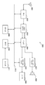
도 9는 도 8에 도시한 화상 복호 장치(60)의 역양자화·역직교 변환부(63)의 상세한 구성의 일례를 나타내는 블록도이다. 도 9를 참조하면, 역양자화·역직교 변환부(63)는 행렬 생성부(210), 선택부(230), 역양자화부(240) 및 역직교 변환부(250)를 갖는다.9 is a block diagram showing an example of a detailed configuration of the inverse quantization / inverse
(1)행렬 생성부(1)
행렬 생성부(210)는 부호화 스트림의 시퀀스마다 및 픽처마다 어떤 하나의 크기의 변환 단위에 대응하는 양자화 행렬로부터 다른 하나 이상의 크기의 변환 단위에 대응하는 양자화 행렬을 생성한다. 양자화 행렬의 생성의 기초가 되는 변환 단위의 크기는 전형적으로는 복수의 변환 단위의 크기 중 최소의 크기이어도 된다. 본 실시 형태에서는, 행렬 생성부(210)는 최소의 크기인 4×4의 양자화 행렬로부터, 보다 큰 크기에 관한 차분 행렬 정보를 사용하여 8×8, 16×16 및 32×32의 양자화 행렬을 생성한다.The
(2)선택부(2)
선택부(230)는, 크기가 상이한 복수의 변환 단위로부터, 복호되는 화상 데이터의 역직교 변환을 위하여 사용되는 변환 단위(TU)를 선택한다. 선택부(230)에 의해 선택될 수 있는 변환 단위 크기의 후보는, 예를 들어 H.264/AVC에서는 4×4 및 8×8을 포함하고, HEVC에서는 4×4, 8×8, 16×16 및 32×32를 포함한다. 선택부(230)는, 예를 들어 부호화 스트림의 헤더 내에 포함되는 LCU, SCU 및 split_flag에 기초하여 변환 단위를 선택해도 된다. 그리고, 선택부(230)는, 선택한 변환 단위의 크기를 지정하는 정보를 역양자화부(240) 및 역직교 변환부(250)로 출력한다.The
(3)역양자화부(3) Inverse quantization unit
역양자화부(240)는, 선택부(230)에 의해 선택된 변환 단위에 대응하는 양자화 행렬을 사용하여 화상의 부호화 시에 양자화된 변환 계수 데이터를 역양자화한다. 여기서 역양자화 처리를 위하여 사용되는 양자화 행렬은 행렬 생성부(210)에 의해 생성되는 행렬을 포함한다. 즉, 예를 들어 선택부(230)에 의해 8×8, 16×16 또는 32×32의 변환 단위가 선택된 경우에는, 선택된 변환 단위에 대응하는 양자화 행렬로서 행렬 생성부(210)에 의해 4×4의 양자화 행렬로부터 생성된 양자화 행렬이 사용될 수 있다. 그리고, 역양자화부(240)는 역양자화한 변환 계수 데이터를 역직교 변환부(250)로 출력한다.The
(4)역직교 변환부(4) Inverse orthogonal transformation unit
역직교 변환부(250)는, 부호화 시에 사용된 직교 변환 방식에 따라 역양자화부(240)에 의해 역양자화된 변환 계수 데이터를 상기 선택된 변환 단위로 역직교 변환함으로써 예측 오차 데이터를 생성한다. 그리고, 역직교 변환부(250)는 생성한 예측 오차 데이터를 가산부(65)로 출력한다.The inverse
[3-3. 행렬 생성부의 상세한 구성예][3-3. Detailed Configuration Example of Matrix Generation Unit]
도 10은 도 9에 도시한 역양자화·역직교 변환부(63)의 행렬 생성부(210)의 더욱 상세한 구성의 일례를 나타내는 블록도이다. 도 10을 참조하면, 행렬 생성부(210)는 기초 행렬 취득부(212), 차분 취득부(214), 예측부(216), 재구축부(218) 및 양자화 행렬 버퍼(220)를 포함한다.FIG. 10 is a block diagram showing an example of a more detailed configuration of the
(1)기초 행렬 취득부(1) Basic matrix acquisition unit
기초 행렬 취득부(212)는 가역 복호부(62)로부터 입력되는 기초 행렬 정보를 취득한다. 본 실시 형태에 있어서, 기초 행렬 정보는 상술한 바와 같이 최소의 크기인 4×4의 양자화 행렬(SL1)을 특정하는 정보이다. 그리고, 기초 행렬 취득부(212)는 취득한 기초 행렬 정보로부터 특정되는 4×4의 양자화 행렬(SL1)을 양자화 행렬 버퍼(220)에 기억시킨다. 또한, 기초 행렬 취득부(212)는, 시퀀스마다 또는 픽처마다 취득되는 행렬 종류별 플래그가 「0」이면, 기초 행렬 정보를 취득하지 않고, 미리 정해진 4×4의 양자화 행렬을 양자화 행렬 버퍼(220)에 기억시킨다. 또한, 기초 행렬 취득부(212)는, 픽처마다 취득되는 갱신 플래그가 「0」이면, 이전의 처리에 의해 양자화 행렬 버퍼(220)에 기억시킨 양자화 행렬(SL1)을 갱신하지 않는다. 또한, 기초 행렬 취득부(212)는 4×4의 양자화 행렬(SL1)을 예측부(216)로 출력한다.The base
(2)차분 취득부(2) Difference Acquisition Unit
차분 취득부(214)는 가역 복호부(62)로부터 입력되는 차분 행렬 정보를 취득한다. 본 실시 형태에 있어서, 차분 행렬 정보는, 상술한 바와 같이 4×4의 양자화 행렬(SL1)로부터 예측되는 예측 행렬(PSL2, PSL3 및 PSL4)과 양자화 행렬(SL2, SL3 및 SL4)의 차분을 나타내는 차분 행렬(DSL2, DSL3 및 DSL4)을 특정하는 정보이다. 차분 취득부(214)는 차분 행렬 정보에 의해 특정되는 차분 행렬(DSL2, DSL3 및 DSL4)을 재구축부(218)로 출력한다. 또한, 차분 취득부(214)는, 시퀀스마다 또는 픽처마다 취득되는 행렬 종류별 플래그가 「0」이며 또는 차분 플래그가 「0」이면, 차분 행렬 정보를 취득하지 않고, 대응하는 크기의 차분 행렬을 0행렬로 한다. 또한, 차분 취득부(214)는, 픽처마다 취득되는 갱신 플래그가 「0」이면, 대응하는 크기에 대하여 차분 행렬을 출력하지 않는다.The
(3)예측부(3)
예측부(216)는, 기초 행렬 취득부(212)로부터 입력되는 기초 행렬, 즉 본 실시 형태에 있어서는 4×4의 양자화 행렬(SL1)로부터, 화상의 부호화 시에 사용된 예측식(예를 들어, 상술한 예측식 (2) 또는 (3))에 따라 보다 큰 크기의 8×8의 예측 행렬(PSL2)을 산출한다. 또한, 예측부(216)는, 산출된 8×8의 예측 행렬(PSL2)을 사용하여 재구축부(218)에 의해 재구축되는 양자화 행렬(SL2)로부터 16×16의 예측 행렬(PSL3)을 산출한다. 또한, 예측부(216)는, 산출된 16×16의 예측 행렬(PSL3)을 사용하여 재구축부(218)에 의해 재구축되는 양자화 행렬(SL3)로부터 32×32의 예측 행렬(PSL4)을 산출한다. 예측부(216)는 예측 행렬(PSL2, PSL3 및 PSL4)을 각각 재구축부(218)로 출력한다. 또한, 예측부(216)는, 행렬 종류별 플래그가 「0」인 크기에 대해서는 예측 행렬을 생성하지 않고, 보다 큰 크기의 예측 행렬의 산출을 위해서 미리 정해진 양자화 행렬을 사용한다. 또한, 기초 행렬 취득부(212)는, 갱신 플래그가 「0」인 크기에 대해서도 예측 행렬을 생성하지 않고, 보다 큰 크기의 예측 행렬의 산출을 위해서 이전의 처리에서 생성된 양자화 행렬을 사용한다.The predicting
(4)재구축부(4)
재구축부(218)는, 예측부(216)로부터 입력되는 예측 행렬(PSL2, PSL3 및 PSL4)과 차분 취득부(214)로부터 입력되는 차분 행렬(DSL2, DSL3 및 DSL4)을 가산함으로써 양자화 행렬(SL2, SL3 및 SL4)을 각각 재구축한다:The

그리고, 재구축부(218)는 재구축한 8×8, 16×16 및 32×32의 양자화 행렬(SL2, SL3 및 SL4)을 양자화 행렬 버퍼(220)에 기억시킨다. 또한, 재구축부(218)는, 시퀀스마다 또는 픽처마다 취득되는 행렬 종류별 플래그가 「0」이면, 대응하는 크기의 양자화 행렬로서 미리 정해진 양자화 행렬을 양자화 행렬 버퍼(220)에 기억시킨다. 또한, 기초 행렬 취득부(212)는, 픽처마다 취득되는 갱신 플래그가 「0」이면, 이전의 처리에 의해 양자화 행렬 버퍼(220)에 기억시킨 대응하는 크기의 양자화 행렬(SL2, SL3 또는 SL4)을 갱신하지 않는다.Then, the reconstructing
(5)양자화 행렬 버퍼(5) Quantization matrix buffer
양자화 행렬 버퍼(220)는, 기초 행렬 취득부(212)에 의해 특정되는 양자화 행렬(SL1), 및 재구축부(218)에 의해 재구축되는 양자화 행렬(SL2, SL3 및 SL4)을 일시적으로 기억한다. 양자화 행렬 버퍼(220)에 의해 기억되는 이들 양자화 행렬(SL1, SL2, SL3 및 SL4)은, 양자화된 변환 계수 데이터의 역양자화부(240)에 의한 역양자화 처리를 위하여 사용된다.The
또한, 본 항에서 설명한 화상 복호 장치(60)의 역양자화·역직교 변환부(63)의 구성은, 도 1에 도시한 화상 부호화 장치(10)의 역양자화부(21) 및 역직교 변환부(22)에도 적용될 수 있다.The configuration of the inverse quantization and inverse
<4. 일실시 형태에 관한 복호시의 처리 흐름><4. Process Flow at Decoding in One Embodiment>
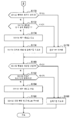
도 11a 및 도 11b는 본 실시 형태에 관한 복호시의 처리 흐름의 제1 예를 나타내는 흐름도이다. 당해 흐름도에 나타난 처리는 주로 부호화 스트림의 시퀀스마다 행렬 생성부(210)에 의해 실행될 수 있다.11A and 11B are flowcharts showing a first example of the processing flow at the time of decoding according to the present embodiment. The processing shown in the flow chart can be executed by the
도 11a를 참조하면, 우선, 행렬 생성부(210)는, 당해 시퀀스의 시퀀스 파라미터 세트에 포함되는 행렬 종류별 플래그에 기초하여 4×4의 양자화 행렬이 유저에 의해 정의되는 행렬인지 여부를 판정한다(스텝S202). 여기서 4×4의 양자화 행렬이 유저에 의해 정의되는 행렬인 경우에는, 행렬 생성부(210)는 기초 행렬 정보를 사용해서 4×4의 양자화 행렬을 설정한다(즉, 양자화 행렬 버퍼(220)에 기억시킴)(스텝S204). 한편, 4×4의 양자화 행렬이 미리 정해진 행렬인 경우에는, 행렬 생성부(210)는 미리 정해진 4×4의 양자화 행렬을 설정한다(스텝S206).Referring to FIG. 11A, the
이어서, 행렬 생성부(210)는 8×8의 양자화 행렬이 유저에 의해 정의되는 행렬인지 여부를 판정한다(스텝S212). 여기서 8×8의 양자화 행렬이 유저에 의해 정의되는 행렬인 경우에는, 행렬 생성부(210)는 예를 들어 상술한 예측식 (2) 또는 (3)을 따라서 4×4의 양자화 행렬로부터 8×8의 예측 행렬을 산출하고, 산출한 예측 행렬과 8×8의 차분 행렬을 가산한다. 그에 의해 8×8의 양자화 행렬이 재구축된다(스텝S214). 또한, 8×8의 차분 플래그가 「0」이면, 차분 행렬은 0행렬이며, 8×8의 예측 행렬이 그대로 양자화 행렬로서 설정될 수 있다. 한편, 8×8의 양자화 행렬이 미리 정해진 행렬인 경우에는, 행렬 생성부(210)는 미리 정해진 8×8의 양자화 행렬을 설정한다(스텝S216).Subsequently, the
이어서, 도 11b를 참조하면, 행렬 생성부(210)는 16×16의 양자화 행렬이 유저에 의해 정의되는 행렬인지 여부를 판정한다(스텝S222). 여기서 16×16의 양자화 행렬이 유저에 의해 정의되는 행렬인 경우에는, 행렬 생성부(210)는 8×8의 양자화 행렬로부터 16×16의 예측 행렬을 산출하고, 산출한 예측 행렬과 16×16의 차분 행렬을 가산한다. 그에 의해 16×16의 양자화 행렬이 재구축된다(스텝S224). 또한, 16×16의 차분 플래그가 「0」이면, 차분 행렬은 0행렬이며, 16×16의 예측 행렬이 그대로 양자화 행렬로서 설정될 수 있다. 한편, 16×16의 양자화 행렬이 미리 정해진 행렬인 경우에는, 행렬 생성부(210)는 미리 정해진 16×16의 양자화 행렬을 설정한다(스텝S226).Referring to FIG. 11B, the
이어서, 행렬 생성부(210)는 32×32의 양자화 행렬이 유저에 의해 정의되는 행렬인지 여부를 판정한다(스텝S232). 여기서 32×32의 양자화 행렬이 유저에 의해 정의되는 행렬인 경우에는, 행렬 생성부(210)는 16×16의 양자화 행렬로부터 32×32의 예측 행렬을 산출하고, 산출한 예측 행렬과 32×32의 차분 행렬을 가산한다. 그에 의해 32×32의 양자화 행렬이 재구축된다(스텝S234). 또한, 32×32의 차분 플래그가 「0」이면, 차분 행렬은 0행렬이며, 32×32의 예측 행렬이 그대로 양자화 행렬로서 설정될 수 있다. 한편, 32×32의 양자화 행렬이 미리 정해진 행렬인 경우에는, 행렬 생성부(210)는 미리 정해진 32×32의 양자화 행렬을 설정한다(스텝S236).Subsequently, the
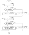
도 12a 및 도 12b는 본 실시 형태에 관한 복호시의 처리 흐름의 제2 예를 나타내는 흐름도이다. 당해 흐름도에 나타난 처리는 주로 부호화 스트림의 픽처마다 행렬 생성부(210)에 의해 실행될 수 있다.12A and 12B are flowcharts showing a second example of the processing flow at the time of decoding according to the present embodiment. The processing shown in the flow chart can be mainly executed by the
도 12a를 참조하면, 우선, 행렬 생성부(210)는, 픽처 파라미터 세트에 포함되는 갱신 플래그에 기초하여 4×4의 양자화 행렬이 당해 픽처에 있어서 갱신될지 여부를 판정한다(스텝S250). 여기서, 4×4의 양자화 행렬이 갱신되지 않을 경우에는 스텝S252 내지 S256의 처리는 스킵된다. 4×4의 양자화 행렬이 갱신될 경우에는, 행렬 생성부(210)는 행렬 종류별 플래그에 기초하여 새로운 4×4의 양자화 행렬이 유저에 의해 정의되는 행렬인지 여부를 판정한다(스텝S252). 여기서 4×4의 양자화 행렬이 유저에 의해 정의되는 행렬인 경우에는, 행렬 생성부(210)는 기초 행렬 정보를 사용해서 4×4의 양자화 행렬을 설정한다(스텝S254). 한편, 4×4의 양자화 행렬이 미리 정해진 행렬인 경우에는, 행렬 생성부(210)는 미리 정해진 4×4의 양자화 행렬을 설정한다(스텝S256).Referring to FIG. 12A, first, the
이어서, 행렬 생성부(210)는, 갱신 플래그에 기초하여 8×8의 양자화 행렬이 당해 픽처에 있어서 갱신될지 여부를 판정한다(스텝S260). 여기서, 8×8의 양자화 행렬이 갱신되지 않을 경우에는 스텝S262 내지 S266의 처리는 스킵된다. 8×8의 양자화 행렬이 갱신될 경우에는, 행렬 생성부(210)는 행렬 종류별 플래그에 기초하여 새로운 8×8의 양자화 행렬이 유저에 의해 정의되는 행렬인지 여부를 판정한다(스텝S262). 여기서 8×8의 양자화 행렬이 유저에 의해 정의되는 행렬인 경우에는, 행렬 생성부(210)는 4×4의 양자화 행렬이 갱신되었는지 여부에 의하지 않고, 새로운 픽처의 4×4의 양자화 행렬로부터 8×8의 예측 행렬을 산출하고, 산출한 예측 행렬과 8×8의 차분 행렬을 가산한다. 그에 의해 8×8의 양자화 행렬이 재구축된다(스텝S264). 또한, 8×8의 차분 플래그가 「0」이면, 차분 행렬은 0행렬이며, 8×8의 예측 행렬이 그대로 양자화 행렬로서 설정될 수 있다. 한편, 8×8의 양자화 행렬이 미리 정해진 행렬인 경우에는, 행렬 생성부(210)는 미리 정해진 8×8의 양자화 행렬을 설정한다(스텝S266).Subsequently, the
이어서, 도 12b를 참조하면, 행렬 생성부(210)는 갱신 플래그에 기초하여 16×16의 양자화 행렬이 당해 픽처에 있어서 갱신될지 여부를 판정한다(스텝S270). 여기서, 16×16의 양자화 행렬이 갱신되지 않을 경우에는 스텝S272 내지 S276의 처리는 스킵된다. 16×16의 양자화 행렬이 갱신될 경우에는, 행렬 생성부(210)는 행렬 종류별 플래그에 기초하여 새로운 16×16의 양자화 행렬이 유저에 의해 정의되는 행렬인지 여부를 판정한다(스텝S272). 여기서 16×16의 양자화 행렬이 유저에 의해 정의되는 행렬인 경우에는, 행렬 생성부(210)는 8×8의 양자화 행렬이 갱신되었는지 여부에 의하지 않고, 새로운 픽처의 8×8의 양자화 행렬로부터 16×16의 예측 행렬을 산출하고, 산출한 예측 행렬과 16×16의 차분 행렬을 가산한다. 그에 의해 16×16의 양자화 행렬이 재구축된다(스텝S274). 또한, 16×16의 차분 플래그가 「0」이면, 차분 행렬은 0행렬이며, 16×16의 예측 행렬이 그대로 양자화 행렬로서 설정될 수 있다. 한편, 16×16의 양자화 행렬이 미리 정해진 행렬인 경우에는, 행렬 생성부(210)는 미리 정해진 16×16의 양자화 행렬을 설정한다(스텝S276).Next, referring to FIG. 12B, the
이어서, 행렬 생성부(210)는, 갱신 플래그에 기초하여 32×32의 양자화 행렬이 당해 픽처에 있어서 갱신될지 여부를 판정한다(스텝S280). 여기서, 32×32의 양자화 행렬이 갱신되지 않을 경우에는 스텝S282 내지 S286의 처리는 스킵된다. 32×32의 양자화 행렬이 갱신될 경우에는, 행렬 생성부(210)는 행렬 종류별 플래그에 기초하여 새로운 32×32의 양자화 행렬이 유저에 의해 정의되는 행렬인지 여부를 판정한다(스텝S282). 여기서 32×32의 양자화 행렬이 유저에 의해 정의되는 행렬인 경우에는, 행렬 생성부(210)는 16×16의 양자화 행렬이 갱신되었는지 여부에 의하지 않고, 새로운 픽처의 16×16의 양자화 행렬로부터 32×32의 예측 행렬을 산출하고, 산출한 예측 행렬과 32×32의 차분 행렬을 가산한다. 그에 의해 32×32의 양자화 행렬이 재구축된다(스텝S284). 또한, 32×32의 차분 플래그가 「0」이면, 차분 행렬은 0행렬이며, 32×32의 예측 행렬이 그대로 양자화 행렬로서 설정될 수 있다. 한편, 32×32의 양자화 행렬이 미리 정해진 행렬인 경우에는, 행렬 생성부(210)는 미리 정해진 32×32의 양자화 행렬을 설정한다(스텝S286).Subsequently, the
이와 같이, 어느 하나의 양자화 행렬에 기초하여 다른 양자화 행렬을 예측하는 방법을 사용함으로써 예측 대상의 양자화 행렬에 대하여 차분의 정보만이 부호화측으로부터 복호측에 전송되는 경우에도 복호측에서 적절하게 양자화 행렬을 재구축할 수 있다. 따라서, 양자화 행렬의 수가 많아지는 경우에도 부호량의 증가가 효과적으로 억제된다.By using the method of predicting another quantization matrix based on any one quantization matrix, even when only difference information is transmitted from the encoding side to the decoding side with respect to the quantization matrix to be predicted, the quantization matrix Can be reconstructed. Therefore, even when the number of quantization matrices increases, the increase of the code amount is effectively suppressed.
또한, 본 명세서에서는, 주로 하나의 변환 단위의 크기에 대해서 1종의 양자화 행렬만이 설정되는 예를 설명하였다. 그러나, 이러한 예에 한정되지 않고, 하나의 변환 단위의 크기에 대하여 복수 종류의 양자화 행렬이 설정되어도 된다. 그 경우, 시퀀스 파라미터 세트 및 픽처 파라미터 세트에는 복수 종류의 양자화 행렬 중 어느 하나의 양자화 행렬을 보다 큰 크기의 양자화 행렬 예측의 기초로 해야할지를 나타내는 추가적인 플래그가 포함될 수 있다. 또한, 하나의 변환 단위의 크기에 대하여 복수 종류의 양자화 행렬이 설정되고, 1픽처 내에서 슬라이스마다 또는 블록마다 양자화 행렬이 선택적으로 전환되어도 된다.In the present specification, an example has been described in which one kind of quantization matrix is mainly set for the size of one conversion unit. However, the present invention is not limited to this example, and a plurality of kinds of quantization matrices may be set for the size of one conversion unit. In that case, the sequence parameter set and the picture parameter set may include an additional flag indicating which one of the plurality of kinds of quantization matrices should be the basis of the quantization matrix prediction of a larger size. Further, a plurality of kinds of quantization matrices may be set for the size of one conversion unit, and the quantization matrix may be selectively switched for each slice or each block in one picture.
<5. 변형예><5. Modifications>
또한, 상술한 바와 같이, 본 명세서에서 개시한 기술은, 보다 큰 크기의 양자화 행렬로부터 보다 작은 크기의 양자화 행렬을 예측하는 방식으로 실현되어도 된다. 예를 들어, 8×8의 양자화 행렬(SL2)을 다음과 같이 정의한다:Further, as described above, the technique disclosed in this specification may be realized in a manner of predicting a quantization matrix of a smaller size from a quantization matrix of a larger size. For example, an 8 × 8 quantization matrix (SL2) is defined as follows:

화상 부호화 장치(10)의 직교 변환·양자화부(14)의 예측부(152)는 이러한 양자화 행렬(SL2)로부터, 예를 들어 다음의 예측식(12)를 따라서 4×4의 예측 행렬(PSL1)을 산출할 수 있다:The predicting

예측식(12)를 참조하면, 예측 행렬(PSL1)은 양자화 행렬(SL2)의 요소를 1행 걸러서 또한 1열 걸러서 씨닝함으로써 생성된 행렬이다. 씨닝되는 요소의 위치는 예측식(12)의 예에 한정되지 않고, 다른 위치이어도 된다. 또한, 씨닝되는 요소의 수를 증가시킴으로써 1변의 크기가 4분의 1 이하인 예측 행렬을 양자화 행렬로부터 생성할 수도 있다.Referring to the prediction equation (12), the prediction matrix PSL1 is a matrix generated by thinning the elements of the quantization matrix SL2 one row at a time and one column at a time. The position of the element to be thinned is not limited to the example of the prediction expression (12), but may be another position. Also, by increasing the number of elements to be thinned, a prediction matrix having a size of one side of one quarter or less can be generated from the quantization matrix.
그 대신에, 예측 행렬(PSL1)은 다음 예측식(13)을 따라서 양자화 행렬(SL2)로부터 산출되어도 된다:Instead, the prediction matrix PSL1 may be calculated from the quantization matrix SL2 along the following prediction equation (13): < EMI ID =

예측식(13)을 참조하면, 예측 행렬(PSL1)은 양자화 행렬(SL2)에 있어서 상하 좌우로 서로 인접하는 4개의 요소의 평균을 예측 행렬(PSL1)의 하나의 요소로서 계산함으로써 생성된 행렬이다. 또한, 상하 좌우로 서로 인접하는 보다 많은(예를 들어 16개) 요소의 평균을 계산함으로써 1변의 크기가 4분의 1 이하인 예측 행렬을 양자화 행렬로부터 생성할 수도 있다. 또한, 예측식(13)과 같은 평균값 대신에 중앙값, 최소값 또는 최대값 등이라는 다른 종류의 대표값이 복수의 요소로부터 계산되어도 된다.Referring to the prediction equation (13), the prediction matrix PSL1 is a matrix generated by calculating an average of four elements adjacent to each other in up, down, right, and left directions in the quantization matrix SL2 as one element of the prediction matrix PSL1 . Further, by calculating the average of more (for example, 16) elements that are adjacent to each other in the up, down, left, and right directions, a prediction matrix whose size is one quarter or less can be generated from the quantization matrix. Instead of the average value such as the prediction equation (13), another kind of representative value such as a median value, a minimum value, or a maximum value may be calculated from a plurality of elements.
보다 큰 크기의 양자화 행렬로부터 보다 작은 크기의 예측 행렬이 산출될 경우에도, 차분 연산부(154)는 예측부(152)로부터 입력되는 예측 행렬과 대응하는 양자화 행렬의 차분을 나타내는 차분 행렬을 산출하고, 산출한 차분 행렬을 나타내는 차분 행렬 정보를 가역 부호화부(16)로 출력한다. 그리고, 화상 복호 장치(60)의 역양자화·역직교 변환부(63)의 행렬 생성부(210)는, 기초 행렬 정보에 의해 특정되는 양자화 행렬로부터 보다 작은 크기의 양자화 행렬을 상술한 어느 한쪽의 예측식 및 차분 행렬 정보를 사용하여 생성한다.Even when a prediction matrix of a smaller size is calculated from a quantization matrix of a larger size, the
도 13a 및 도 13b는 본 변형예에 관한 부호화시의 처리 흐름의 일례를 나타내는 흐름도이다. 당해 흐름도에 나타난 처리는 주로 부호화 스트림의 시퀀스마다 행렬 처리부(150) 및 가역 부호화부(16)에 의해 실행될 수 있다.13A and 13B are flowcharts showing an example of the processing flow in encoding according to the present modification. The processing shown in the flow chart can be executed by the
도 13a를 참조하면, 우선, 행렬 처리부(150)는 당해 시퀀스에 있어서 양자화부(130)에 의해 사용되는 양자화 행렬의 세트를 양자화 행렬 버퍼(140)로부터 취득한다(스텝S300). 여기에서는 일례로서 4×4, 8×8, 16×16 및 32×32의 각 크기에 대응하는 양자화 행렬이 양자화 행렬의 세트에 포함되는 것으로 한다.13A, first, the
이어서, 행렬 처리부(150)는 32×32의 양자화 행렬이 유저에 의해 정의되는 행렬인지 여부를 판정한다(스텝S302). 여기서 32×32의 양자화 행렬이 유저에 의해 정의되는 행렬인 경우에는, 가역 부호화부(16)는 행렬 종류별 플래그(=1) 및 32×32의 양자화 행렬을 나타내는 기초 행렬 정보를 부호화한다(스텝S306). 한편, 32×32의 양자화 행렬이 미리 정해진 행렬인 경우에는, 가역 부호화부(16)는 행렬 종류별 플래그(=0)만을 부호화한다(스텝S308).Subsequently, the
이어서, 행렬 처리부(150)는 16×16의 양자화 행렬이 유저에 의해 정의되는 행렬인지 여부를 판정한다(스텝S312). 여기서 16×16의 양자화 행렬이 유저에 의해 정의되는 행렬인 경우에는, 행렬 처리부(150)는 예를 들어 상술한 예측식(12) 또는 (13)에 따라서 32×32의 양자화 행렬로부터 16×16의 예측 행렬을 산출한다(스텝S314). 그리고, 가역 부호화부(16)는 행렬 종류별 플래그(=1), 차분 플래그 및 16×16의 양자화 행렬과 산출된 예측 행렬의 차분을 나타내는 차분 행렬 정보(차분이 있는 경우만)를 부호화한다(스텝S316). 한편, 16×16의 양자화 행렬이 미리 정해진 행렬인 경우에는, 가역 부호화부(16)는 행렬 종류별 플래그(=0)만을 부호화한다(스텝S318).Subsequently, the
이어서, 도 13b를 참조하면, 행렬 처리부(150)는 8×8의 양자화 행렬이 유저에 의해 정의되는 행렬인지 여부를 판정한다(스텝S322). 여기서 8×8의 양자화 행렬이 유저에 의해 정의되는 행렬인 경우에는, 행렬 처리부(150)는 16×16의 양자화 행렬로부터 8×8의 예측 행렬을 산출한다(스텝S324). 그리고, 가역 부호화부(16)는 행렬 종류별 플래그(=1), 차분 플래그 및 8×8의 양자화 행렬과 산출된 예측 행렬의 차분을 나타내는 차분 행렬 정보(차분이 있는 경우만)를 부호화한다(스텝S326). 한편, 8×8의 양자화 행렬이 미리 정해진 행렬인 경우에는, 가역 부호화부(16)는 행렬 종류별 플래그(=0)만을 부호화한다(스텝S328).Next, referring to FIG. 13B, the
이어서, 행렬 처리부(150)는 4×4의 양자화 행렬이 유저에 의해 정의되는 행렬인지 여부를 판정한다(스텝S332). 여기서 4×4의 양자화 행렬이 유저에 의해 정의되는 행렬인 경우에는, 행렬 처리부(150)는 8×8의 양자화 행렬로부터 4×4의 예측 행렬을 산출한다(스텝S334). 그리고, 가역 부호화부(16)는, 행렬 종류별 플래그(=1), 차분 플래그 및 4×4의 양자화 행렬과 산출된 예측 행렬의 차분을 나타내는 차분 행렬 정보(차분이 있는 경우만)를 부호화한다(스텝S336). 한편, 4×4의 양자화 행렬이 미리 정해진 행렬인 경우에는, 가역 부호화부(16)는 행렬 종류별 플래그(=0)만을 부호화한다(스텝S338).Subsequently, the
이와 같이, 본 변형예에서는, 양자화 행렬을 SPS에서 정의할 때, 크기가 큰 양자화 행렬부터 순서대로 예측 행렬의 산출 및 부호화가 행해질 수 있다. 양자화 행렬을 PPS에서 갱신할 경우에도, 마찬가지로 크기가 큰 양자화 행렬부터 순서대로 예측 행렬의 산출 및 부호화가 행해져도 된다.As described above, in this modification, when the quantization matrix is defined in the SPS, the prediction matrix can be calculated and encoded in order from the quantization matrix having a large size. When the quantization matrix is updated in the PPS, the prediction matrix may be calculated and encoded in order from the quantization matrix having a large size as well.
도 14a 및 도 14b는 본 실시 형태에 관한 복호시의 처리 흐름의 일례를 나타내는 흐름도이다. 당해 흐름도에 나타난 처리는 주로 부호화 스트림의 시퀀스마다 행렬 생성부(210)에 의해 실행될 수 있다.14A and 14B are flowcharts showing an example of the processing flow at the time of decoding according to the present embodiment. The processing shown in the flow chart can be executed by the
도 14a를 참조하면, 우선, 행렬 생성부(210)는 당해 시퀀스의 시퀀스 파라미터 세트에 포함되는 행렬 종류별 플래그에 기초하여 32×32의 양자화 행렬이 유저에 의해 정의되는 행렬인지 여부를 판정한다(스텝S402). 여기서 32×32의 양자화 행렬이 유저에 의해 정의되는 행렬인 경우에는, 행렬 생성부(210)는 기초 행렬 정보를 사용해서 32×32의 양자화 행렬을 설정한다(즉, 양자화 행렬 버퍼(220)에 기억시킴)(스텝S404). 한편, 32×32의 양자화 행렬이 미리 정해진 행렬인 경우에는, 행렬 생성부(210)는 미리 정해진 32×32의 양자화 행렬을 설정한다(스텝S406).14A, first, the
이어서, 행렬 생성부(210)는 16×16의 양자화 행렬이 유저에 의해 정의되는 행렬인지 여부를 판정한다(스텝S412). 여기서 16×16의 양자화 행렬이 유저에 의해 정의되는 행렬인 경우에는, 행렬 생성부(210)는 예를 들어 상술한 예측식(12) 또는 (13)에 따라서 32×32의 양자화 행렬로부터 16×16의 예측 행렬을 산출하고, 산출한 예측 행렬과 16×16의 차분 행렬을 가산한다. 그에 의해 16×16의 양자화 행렬이 재구축된다(스텝S414). 또한, 16×16의 차분 플래그가 「0」이면, 차분 행렬은 0행렬이며, 16×16의 예측 행렬이 그대로 양자화 행렬로서 설정될 수 있다. 한편, 16×16의 양자화 행렬이 미리 정해진 행렬인 경우에는, 행렬 생성부(210)는 미리 정해진 16×16의 양자화 행렬을 설정한다(스텝S416).Subsequently, the
이어서, 도 14b를 참조하면, 행렬 생성부(210)는 8×8의 양자화 행렬이 유저에 의해 정의되는 행렬인지 여부를 판정한다(스텝S422). 여기서 8×8의 양자화 행렬이 유저에 의해 정의되는 행렬인 경우에는, 행렬 생성부(210)는 16×16의 양자화 행렬로부터 8×8의 예측 행렬을 산출하고, 산출한 예측 행렬과 8×8의 차분 행렬을 가산한다. 그에 의해 8×8의 양자화 행렬이 재구축된다(스텝S424). 또한, 8×8의 차분 플래그가 「0」이면, 차분 행렬은 0행렬이며, 8×8의 예측 행렬이 그대로 양자화 행렬로서 설정될 수 있다. 한편, 8×8의 양자화 행렬이 미리 정해진 행렬인 경우에는, 행렬 생성부(210)는 미리 정해진 8×8의 양자화 행렬을 설정한다(스텝S426).14B, the
이어서, 행렬 생성부(210)는 4×4의 양자화 행렬이 유저에 의해 정의되는 행렬인지 여부를 판정한다(스텝S432). 여기서 4×4의 양자화 행렬이 유저에 의해 정의되는 행렬인 경우에는, 행렬 생성부(210)는 8×8의 양자화 행렬로부터 4×4의 예측 행렬을 산출하고, 산출한 예측 행렬과 4×4의 차분 행렬을 가산한다. 그에 의해 4×4의 양자화 행렬이 재구축된다(스텝S434). 또한, 4×4의 차분 플래그가 「0」이면, 차분 행렬은 0행렬이며, 4×4의 예측 행렬이 그대로 양자화 행렬로서 설정될 수 있다. 한편, 4×4의 양자화 행렬이 미리 정해진 행렬인 경우에는, 행렬 생성부(210)는 미리 정해진 4×4의 양자화 행렬을 설정한다(스텝S436).Subsequently, the
이와 같이, 본 변형예에서는, 양자화 행렬을 SPS로부터 복호할 때, 크기가 큰 양자화 행렬부터 순서대로 행렬이 재구축될 수 있다. 양자화 행렬을 PPS에서 갱신할 경우에도, 마찬가지로 크기가 큰 양자화 행렬부터 순서대로 행렬이 재구축되면 된다.As described above, in this modification, when decoding the quantization matrix from the SPS, the matrix can be reconstructed in order from the quantization matrix having a large size. Even when the quantization matrix is updated in the PPS, the matrix may be reconstructed in order from the quantization matrix having the largest size.
<6. 응용예><6. Application example>
상술한 실시 형태에 관한 화상 부호화 장치(10) 및 화상 복호 장치(60)는 위성 방송, 케이블 TV 등의 유선 방송, 인터넷 상에서의 배신 및 셀룰러 통신에 의한 단말기에의 배신 등에 있어서의 송신기 또는 수신기, 광 디스크, 자기 디스크 및 플래시 메모리 등의 매체에 화상을 기록하는 기록 장치, 또는, 이들 기억 매체로부터 화상을 재생하는 재생 장치 등의 다양한 전자 기기에 응용될 수 있다. 이하, 4개의 응용예에 대하여 설명한다.The
[6-1. 제1 응용예][6-1. First application example]
도 15는 상술한 실시 형태를 적용한 텔레비전 장치의 개략적인 구성의 일례를 나타내고 있다. 텔레비전 장치(900)는 안테나(901), 튜너(902), 디멀티플렉서(903), 디코더(904), 영상 신호 처리부(905), 표시부(906), 음성 신호 처리부(907), 스피커(908), 외부 인터페이스(909), 제어부(910), 유저 인터페이스(911) 및 버스(912)를 구비한다.Fig. 15 shows an example of a schematic configuration of a television apparatus to which the above-described embodiment is applied. The
튜너(902)는 안테나(901)를 통하여 수신되는 방송 신호로부터 원하는 채널의 신호를 추출하고, 추출한 신호를 복조한다. 그리고, 튜너(902)는 복조에 의해 얻어진 부호화 비트 스트림을 디멀티플렉서(903)로 출력한다. 즉, 튜너(902)는 화상이 부호화되어 있는 부호화 스트림을 수신하는 텔레비전 장치(900)에 있어서의 전송 수단으로서의 역할을 갖는다.The
디멀티플렉서(903)는 부호화 비트 스트림으로부터 시청 대상 프로그램의 영상 스트림 및 음성 스트림을 분리하고, 분리한 각 스트림을 디코더(904)로 출력한다. 또한, 디멀티플렉서(903)는 부호화 비트 스트림으로부터 EPG(Electronic Program Guide)등의 보조적인 데이터를 추출하고, 추출한 데이터를 제어부(910)에 공급한다. 또한, 디멀티플렉서(903)는 부호화 비트 스트림이 스크램블되어 있는 경우에는 디스크램블을 행해도 된다.The
디코더(904)는 디멀티플렉서(903)로부터 입력되는 영상 스트림 및 음성 스트림을 복호한다. 그리고, 디코더(904)는 복호 처리에 의해 생성되는 영상 데이터를 영상 신호 처리부(905)로 출력한다. 또한, 디코더(904)는 복호 처리에 의해 생성되는 음성 데이터를 음성 신호 처리부(907)로 출력한다.The
영상 신호 처리부(905)는 디코더(904)로부터 입력되는 영상 데이터를 재생하고, 표시부(906)에 영상을 표시시킨다. 또한, 영상 신호 처리부(905)는 네트워크를 통하여 공급되는 어플리케이션 화면을 표시부(906)에 표시시켜도 된다. 또한, 영상 신호 처리부(905)는 영상 데이터에 대해서, 설정에 따라서, 예를 들어 노이즈 제거 등의 추가적인 처리를 행해도 된다. 또한, 영상 신호 처리부(905)는, 예를 들어 메뉴, 버튼 또는 커서 등의 GUI(Graphical User Interface)의 화상을 생성하고, 생성한 화상을 출력 화상에 중첩해도 된다.The video
표시부(906)는 영상 신호 처리부(905)로부터 공급되는 구동 신호에 의해 구동되고, 표시 디바이스(예를 들어, 액정 디스플레이, 플라즈마 디스플레이 또는 OLED 등)의 영상면 상에 영상 또는 화상을 표시한다.The
음성 신호 처리부(907)는 디코더(904)로부터 입력되는 음성 데이터에 대하여 D/A 변환 및 증폭 등의 재생 처리를 행하고, 스피커(908)로부터 음성을 출력시킨다. 또한, 음성 신호 처리부(907)는 음성 데이터에 대하여 노이즈 제거 등의 추가적인 처리를 행해도 된다.The audio
외부 인터페이스(909)는 텔레비전 장치(900)와 외부 기기 또는 네트워크를 접속하기 위한 인터페이스이다. 예를 들어, 외부 인터페이스(909)를 통하여 수신되는 영상 스트림 또는 음성 스트림이 디코더(904)에 의해 복호되어도 된다. 즉, 외부 인터페이스(909)도 또한, 화상이 부호화되어 있는 부호화 스트림을 수신하는 텔레비전 장치(900)에 있어서의 전송 수단으로서의 역할을 갖는다.The
제어부(910)는 CPU(Central Processing Unit) 등의 프로세서, 및 RAM(Random Access Memory) 및 ROM(Read Only Memory) 등의 메모리를 갖는다. 메모리는 CPU에 의해 실행되는 프로그램, 프로그램 데이터, EPG 데이터, 및 네트워크를 통하여 취득되는 데이터 등을 기억한다. 메모리에 의해 기억되는 프로그램은, 예를 들어 텔레비전 장치(900)의 기동 시에 CPU에 의해 판독되고 실행된다. CPU는 프로그램을 실행함으로써, 예를 들어 유저 인터페이스(911)로부터 입력되는 조작 신호에 따라서 텔레비전 장치(900)의 동작을 제어한다.The
유저 인터페이스(911)는 제어부(910)와 접속된다. 유저 인터페이스(911)는, 예를 들어 유저가 텔레비전 장치(900)를 조작하기 위한 버튼 및 스위치, 및 원격 제어 신호의 수신부 등을 갖는다. 유저 인터페이스(911)는 이들 구성 요소를 거쳐 유저에 의한 조작을 검출해서 조작 신호를 생성하고, 생성한 조작 신호를 제어부(910)로 출력한다.The
버스(912)는 튜너(902), 디멀티플렉서(903), 디코더(904), 영상 신호 처리부(905), 음성 신호 처리부(907), 외부 인터페이스(909) 및 제어부(910)를 서로 접속한다.The
이와 같이 구성된 텔레비전 장치(900)에 있어서, 디코더(904)는 상술한 실시 형태에 관한 화상 복호 장치(60)의 기능을 갖는다. 그에 의해 텔레비전 장치(900)에서의 화상의 복호 시에 양자화 행렬의 수가 많아지는 경우의 부호량의 증가를 억제할 수 있다.In the
[6-2. 제2 응용예][6-2. Second application example]
도 16은 상술한 실시 형태를 적용한 휴대 전화기의 개략적인 구성의 일례를 나타내고 있다. 휴대 전화기(920)는 안테나(921), 통신부(922), 음성 코덱(923), 스피커(924), 마이크로폰(925), 카메라부(926), 화상 처리부(927), 다중 분리부(928), 기록 재생부(929), 표시부(930), 제어부(931), 조작부(932) 및 버스(933)를 구비한다.Fig. 16 shows an example of a schematic configuration of a cellular phone to which the above-described embodiment is applied. The
안테나(921)는 통신부(922)에 접속된다. 스피커(924) 및 마이크로폰(925)은 음성 코덱(923)에 접속된다. 조작부(932)는 제어부(931)에 접속된다. 버스(933)는 통신부(922), 음성 코덱(923), 카메라부(926), 화상 처리부(927), 다중 분리부(928), 기록 재생부(929), 표시부(930) 및 제어부(931)를 서로 접속한다.The
휴대 전화기(920)는 음성 통화 모드, 데이터 통신 모드, 촬영 모드 및 화상 통화 모드를 포함하는 여러가지 동작 모드에서 음성 신호의 송수신, 전자 메일 또는 화상 데이터의 송수신, 화상의 촬상 및 데이터의 기록 등의 동작을 행한다.The
음성 통화 모드에서 마이크로폰(925)에 의해 생성되는 아날로그 음성 신호는 음성 코덱(923)에 공급된다. 음성 코덱(923)은 아날로그 음성 신호를 음성 데이터로 변환하고, 변환된 음성 데이터를 A/D 변환하여 압축한다. 그리고, 음성 코덱(923)은 압축 후의 음성 데이터를 통신부(922)로 출력한다. 통신부(922)는 음성 데이터를 부호화 및 변조하여 송신 신호를 생성한다. 그리고, 통신부(922)는 생성한 송신 신호를 안테나(921)를 통하여 기지국(도시하지 않음)에 송신한다. 또한, 통신부(922)는 안테나(921)를 통하여 수신되는 무선 신호를 증폭하여 및 주파수 변환하여 수신 신호를 취득한다. 그리고, 통신부(922)는 수신 신호를 복조 및 복호하여 음성 데이터를 생성하고, 생성한 음성 데이터를 음성 코덱(923)으로 출력한다. 음성 코덱(923)은 음성 데이터를 신장하여 및 D/A 변환하여 아날로그 음성 신호를 생성한다. 그리고, 음성 코덱(923)은 생성한 음성 신호를 스피커(924)에 공급하여 음성을 출력시킨다.The analog voice signal generated by the
또한, 데이터 통신 모드에서, 예를 들어 제어부(931)는 조작부(932)를 개재하는 유저에 의한 조작에 따라서 전자 메일을 구성하는 문자 데이터를 생성한다. 또한, 제어부(931)는 문자를 표시부(930)에 표시시킨다. 또한, 제어부(931)는 조작부(932)를 개재하는 유저로부터의 송신 지시에 따라서 전자 메일 데이터를 생성하고, 생성한 전자 메일 데이터를 통신부(922)로 출력한다. 통신부(922)는 전자 메일 데이터를 부호화 및 변조하여 송신 신호를 생성한다. 그리고, 통신부(922)는 생성한 송신 신호를 안테나(921)를 통하여 기지국(도시하지 않음)에 송신한다. 또한, 통신부(922)는 안테나(921)를 통하여 수신되는 무선 신호를 증폭하여 및 주파수 변환하여 수신 신호를 취득한다. 그리고, 통신부(922)는 수신 신호를 복조 및 복호하여 전자 메일 데이터를 복원하고, 복원한 전자 메일 데이터를 제어부(931)로 출력한다. 제어부(931)는 표시부(930)에 전자 메일의 내용을 표시시킴과 함께, 전자 메일 데이터를 기록 재생부(929)의 기억 매체에 기억시킨다.In the data communication mode, for example, the
기록 재생부(929)는 판독 기입 가능한 임의의 기억 매체를 갖는다. 예를 들어, 기억 매체는 RAM 또는 플래시 메모리 등의 내장형의 기억 매체이어도 되고, 하드 디스크, 자기 디스크, 광자기 디스크, 광 디스크, USB 메모리, 또는 메모리 카드 등의 외부 장착형의 기억 매체이어도 된다.The recording and
또한, 촬영 모드에서, 예를 들어 카메라부(926)는 피사체를 촬상하여 화상 데이터를 생성하고, 생성한 화상 데이터를 화상 처리부(927)로 출력한다. 화상 처리부(927)는 카메라부(926)로부터 입력되는 화상 데이터를 부호화하고, 부호화 스트림을 기록 재생부(929)의 기억 매체에 기억시킨다.Further, in the photographing mode, for example, the
또한, 화상 통화 모드에서, 예를 들어 다중 분리부(928)는 화상 처리부(927)에 의해 부호화된 영상 스트림과, 음성 코덱(923)으로부터 입력되는 음성 스트림을 다중화하고, 다중화한 스트림을 통신부(922)로 출력한다. 통신부(922)는 스트림을 부호화 및 변조하여 송신 신호를 생성한다. 그리고, 통신부(922)는 생성한 송신 신호를 안테나(921)를 통하여 기지국(도시하지 않음)에 송신한다. 또한, 통신부(922)는 안테나(921)를 통하여 수신되는 무선 신호를 증폭하여 및 주파수 변환하여 수신 신호를 취득한다. 이들 송신 신호 및 수신 신호에는 부호화 비트 스트림이 포함될 수 있다. 그리고, 통신부(922)는 수신 신호를 복조 및 복호하여 스트림을 복원하고, 복원한 스트림을 다중 분리부(928)로 출력한다. 다중 분리부(928)는 입력되는 스트림으로부터 영상 스트림 및 음성 스트림을 분리하고, 영상 스트림을 화상 처리부(927), 음성 스트림을 음성 코덱(923)으로 출력한다. 화상 처리부(927)는 영상 스트림을 복호하여 영상 데이터를 생성한다. 영상 데이터는 표시부(930)에 공급되고, 표시부(930)에 의해 일련의 화상이 표시된다. 음성 코덱(923)은 음성 스트림을 신장하여 및 D/A 변환하여 아날로그 음성 신호를 생성한다. 그리고, 음성 코덱(923)은 생성한 음성 신호를 스피커(924)에 공급하여 음성을 출력시킨다.In the video communication mode, for example, the multiplexing /
이와 같이 구성된 휴대 전화기(920)에 있어서, 화상 처리부(927)는 상술한 실시 형태에 관한 화상 부호화 장치(10) 및 화상 복호 장치(60)의 기능을 갖는다. 그에 의해, 휴대 전화기(920)에서의 화상의 부호화 및 복호 시에 양자화 행렬의 수가 많아지는 경우의 부호량의 증가를 억제할 수 있다.In the
[6-3. 제3 응용예][6-3. Third Application Example]
도 17은 상술한 실시 형태를 적용한 기록 재생 장치의 개략적인 구성의 일례를 나타내고 있다. 기록 재생 장치(940)는, 예를 들어 수신한 방송 프로그램의 음성 데이터 및 영상 데이터를 부호화하여 기록 매체에 기록한다. 또한, 기록 재생 장치(940)는, 예를 들어 다른 장치로부터 취득되는 음성 데이터 및 영상 데이터를 부호화하여 기록 매체에 기록해도 된다. 또한, 기록 재생 장치(940)는, 예를 들어 유저의 지시에 따라서 기록 매체에 기록되어 있는 데이터를 모니터 및 스피커 상에서 재생한다. 이 때, 기록 재생 장치(940)는 음성 데이터 및 영상 데이터를 복호한다.17 shows an example of a schematic configuration of a recording / reproducing apparatus to which the above-described embodiment is applied. The recording / reproducing
기록 재생 장치(940)는 튜너(941), 외부 인터페이스(942), 인코더(943), HDD(Hard Disk Drive)(944), 디스크 드라이브(945), 셀렉터(946), 디코더(947), OSD(On-Screen Display)(948), 제어부(949) 및 유저 인터페이스(950)를 구비한다.The recording and
튜너(941)는 안테나(도시하지 않음)를 통하여 수신되는 방송 신호로부터 원하는 채널의 신호를 추출하고, 추출한 신호를 복조한다. 그리고, 튜너(941)는 복조에 의해 얻어진 부호화 비트 스트림을 셀렉터(946)로 출력한다. 즉, 튜너(941)는 기록 재생 장치(940)에 있어서의 전송 수단으로서의 역할을 갖는다.The
외부 인터페이스(942)는 기록 재생 장치(940)와 외부 기기 또는 네트워크를 접속하기 위한 인터페이스이다. 외부 인터페이스(942)는, 예를 들어 IEEE1394 인터페이스, 네트워크 인터페이스, USB 인터페이스, 또는 플래시 메모리 인터페이스 등이어도 된다. 예를 들어, 외부 인터페이스(942)를 통하여 수신되는 영상 데이터 및 음성 데이터는 인코더(943)에 입력된다. 즉, 외부 인터페이스(942)는 기록 재생 장치(940)에 있어서의 전송 수단으로서의 역할을 갖는다.The
인코더(943)는 외부 인터페이스(942)로부터 입력되는 영상 데이터 및 음성 데이터가 부호화되어 있지 않은 경우에 영상 데이터 및 음성 데이터를 부호화한다. 그리고, 인코더(943)는 부호화 비트 스트림을 셀렉터(946)로 출력한다.The
HDD(944)는 영상 및 음성 등의 콘텐츠 데이터가 압축된 부호화 비트 스트림, 각종 프로그램 및 그 밖의 데이터를 내부의 하드 디스크에 기록한다. 또한, HDD(944)는 영상 및 음성의 재생 시에 이들 데이터를 하드 디스크로부터 판독한다.The
디스크 드라이브(945)는 장착되어 있는 기록 매체에의 데이터의 기록 및 판독을 행한다. 디스크 드라이브(945)에 장착되는 기록 매체는, 예를 들어 DVD 디스크(DVD-Video, DVD- RAM, DVD-R, DVD-RW, DVD+R, DVD+RW 등) 또는 Blu-ray(등록 상표) 디스크 등이어도 된다.The
셀렉터(946)는, 영상 및 음성의 기록 시에는 튜너(941) 또는 인코더(943)로부터 입력되는 부호화 비트 스트림을 선택하고, 선택한 부호화 비트 스트림을 HDD(944) 또는 디스크 드라이브(945)로 출력한다. 또한, 셀렉터(946)는, 영상 및 음성의 재생 시에는 HDD(944) 또는 디스크 드라이브(945)로부터 입력되는 부호화 비트 스트림을 디코더(947)로 출력한다.The
디코더(947)는 부호화 비트 스트림을 복호하여 영상 데이터 및 음성 데이터를 생성한다. 그리고, 디코더(947)는 생성한 영상 데이터를 OSD(948)로 출력한다. 또한, 디코더(904)는 생성한 음성 데이터를 외부 스피커로 출력한다.The
OSD(948)는 디코더(947)로부터 입력되는 영상 데이터를 재생하여 영상을 표시한다. 또한, OSD(948)는 표시하는 영상에, 예를 들어 메뉴, 버튼 또는 커서 등의 GUI의 화상을 중첩해도 된다.The
제어부(949)는 CPU 등의 프로세서, 및 RAM 및 ROM 등의 메모리를 갖는다. 메모리는 CPU에 의해 실행되는 프로그램 및 프로그램 데이터 등을 기억한다. 메모리에 의해 기억되는 프로그램은, 예를 들어 기록 재생 장치(940)의 기동 시에 CPU에 의해 판독되고 실행된다. CPU는 프로그램을 실행함으로써, 예를 들어 유저 인터페이스(950)로부터 입력되는 조작 신호에 따라서 기록 재생 장치(940)의 동작을 제어한다.The
유저 인터페이스(950)는 제어부(949)와 접속된다. 유저 인터페이스(950)는, 예를 들어 유저가 기록 재생 장치(940)를 조작하기 위한 버튼 및 스위치, 및 원격 제어 신호의 수신부 등을 갖는다. 유저 인터페이스(950)는 이들 구성 요소를 개재하여 유저에 의한 조작을 검출하여 조작 신호를 생성하고, 생성한 조작 신호를 제어부(949)로 출력한다.The
이와 같이 구성된 기록 재생 장치(940)에 있어서, 인코더(943)는 상술한 실시 형태에 관한 화상 부호화 장치(10)의 기능을 갖는다. 또한, 디코더(947)는 상술한 실시 형태에 관한 화상 복호 장치(60)의 기능을 갖는다. 그에 의해, 기록 재생 장치(940)에서의 화상의 부호화 및 복호 시에 양자화 행렬의 수가 많아지는 경우의 부호량의 증가를 억제할 수 있다.In the recording / reproducing
[6-4. 제4 응용예][6-4. Fourth application example]
도 18은 상술한 실시 형태를 적용한 촬상 장치의 개략적인 구성의 일례를 나타내고 있다. 촬상 장치(960)는 피사체를 촬상하여 화상을 생성하고, 화상 데이터를 부호화하여 기록 매체에 기록한다.Fig. 18 shows an example of a schematic configuration of an image pickup apparatus to which the above-described embodiment is applied. An
촬상 장치(960)는 광학 블록(961), 촬상부(962), 신호 처리부(963), 화상 처리부(964), 표시부(965), 외부 인터페이스(966), 메모리(967), 미디어 드라이브(968), OSD(969), 제어부(970), 유저 인터페이스(971) 및 버스(972)를 구비한다.The
광학 블록(961)은 촬상부(962)에 접속된다. 촬상부(962)는 신호 처리부(963)에 접속된다. 표시부(965)는 화상 처리부(964)에 접속된다. 유저 인터페이스(971)는 제어부(970)에 접속된다. 버스(972)는 화상 처리부(964), 외부 인터페이스(966), 메모리(967), 미디어 드라이브(968), OSD(969) 및 제어부(970)를 서로 접속한다.The
광학 블록(961)은 포커스 렌즈 및 조리개 기구 등을 갖는다. 광학 블록(961)은 피사체의 광학상을 촬상부(962)의 촬상면에 결상시킨다. 촬상부(962)는 CCD 또는 CMOS 등의 이미지 센서를 갖고, 촬상면에 결상한 광학상을 광전 변환에 의해 전기 신호로서의 화상 신호로 변환한다. 그리고, 촬상부(962)는 화상 신호를 신호 처리부(963)로 출력한다.The
신호 처리부(963)는 촬상부(962)로부터 입력되는 화상 신호에 대하여 니 보정, 감마 보정, 색 보정 등의 다양한 카메라 신호 처리를 행한다. 신호 처리부(963)는 카메라 신호 처리 후의 화상 데이터를 화상 처리부(964)로 출력한다.The
화상 처리부(964)는 신호 처리부(963)로부터 입력되는 화상 데이터를 부호화하고, 부호화 데이터를 생성한다. 그리고, 화상 처리부(964)는 생성한 부호화 데이터를 외부 인터페이스(966) 또는 미디어 드라이브(968)로 출력한다. 또한, 화상 처리부(964)는 외부 인터페이스(966) 또는 미디어 드라이브(968)로부터 입력되는 부호화 데이터를 복호하고, 화상 데이터를 생성한다. 그리고, 화상 처리부(964)는 생성한 화상 데이터를 표시부(965)로 출력한다. 또한, 화상 처리부(964)는 신호 처리부(963)로부터 입력되는 화상 데이터를 표시부(965)로 출력하여 화상을 표시시켜도 된다. 또한, 화상 처리부(964)는 OSD(969)로부터 취득되는 표시용 데이터를 표시부(965)로 출력하는 화상에 중첩해도 된다.The
OSD(969)는, 예를 들어 메뉴, 버튼 또는 커서 등의 GUI의 화상을 생성하고, 생성한 화상을 화상 처리부(964)로 출력한다.The
외부 인터페이스(966)는, 예를 들어 USB 입출력 단자로서 구성된다. 외부 인터페이스(966)는, 예를 들어 화상의 인쇄 시에 촬상 장치(960)와 프린터를 접속한다. 또한, 외부 인터페이스(966)에는 필요에 따라서 드라이브가 접속된다. 드라이브에는, 예를 들어 자기 디스크 또는 광 디스크 등의 리무버블 미디어가 장착되고, 리무버블 미디어로부터 판독되는 프로그램이 촬상 장치(960)에 인스톨될 수 있다. 또한, 외부 인터페이스(966)는 LAN 또는 인터넷 등의 네트워크에 접속되는 네트워크 인터페이스로서 구성되어도 된다. 즉, 외부 인터페이스(966)는 촬상 장치(960)에 있어서의 전송 수단으로서의 역할을 갖는다.The
미디어 드라이브(968)에 장착되는 기록 매체는, 예를 들어 자기 디스크, 광자기 디스크, 광 디스크, 또는 반도체 메모리 등의 판독 기입 가능한 임의의 리무버블 미디어이면 된다. 또한, 미디어 드라이브(968)에 기록 매체가 고정적으로 장착되고, 예를 들어 내장형 하드디스크 드라이브 또는 SSD(Solid State Drive)와 같은 비가반성의 기억부가 구성되어도 된다.The recording medium loaded in the media drive 968 may be any removable medium such as a magnetic disk, a magneto-optical disk, an optical disk, or a semiconductor memory readable and writable. Also, a recording medium may be fixedly mounted on the media drive 968, and a non-reflective storage unit such as an internal hard disk drive or an SSD (Solid State Drive) may be configured.
제어부(970)는 CPU 등의 프로세서, 및 RAM 및 ROM 등의 메모리를 갖는다. 메모리는 CPU에 의해 실행되는 프로그램 및 프로그램 데이터 등을 기억한다. 메모리에 의해 기억되는 프로그램은, 예를 들어 촬상 장치(960)의 기동 시에 CPU에 의해 판독되고 실행된다. CPU는 프로그램을 실행함으로써, 예를 들어 유저 인터페이스(971)로부터 입력되는 조작 신호에 따라서 촬상 장치(960)의 동작을 제어한다.The
유저 인터페이스(971)는 제어부(970)와 접속된다. 유저 인터페이스(971)는, 예를 들어 유저가 촬상 장치(960)를 조작하기 위한 버튼 및 스위치 등을 갖는다. 유저 인터페이스(971)는 이들 구성 요소를 개재하여 유저에 의한 조작을 검출하여 조작 신호를 생성하고, 생성한 조작 신호를 제어부(970)로 출력한다.The
이와 같이 구성된 촬상 장치(960)에 있어서, 화상 처리부(964)는 상술한 실시 형태에 관한 화상 부호화 장치(10) 및 화상 복호 장치(60)의 기능을 갖는다. 그에 의해, 촬상 장치(960)에서의 화상의 부호화 및 복호 시에 양자화 행렬의 수가 많아지는 경우의 부호량의 증가를 억제할 수 있다.In the
<7. 정리><7. Theorem>
여기까지, 도 1 내지 도 18을 사용하여 일실시 형태에 관한 화상 부호화 장치(10) 및 화상 복호 장치(60)에 대하여 설명하였다. 본 실시 형태에 따르면, 크기가 상이한 복수의 변환 단위에 대응하는 복수의 양자화 행렬이 사용되는 경우에, 제1 크기의 변환 단위에 대응하는 제1 양자화 행렬로부터 제2 크기의 변환 단위에 대응하는 제2 양자화 행렬이 예측의 방법을 이용하여 생성된다. 따라서, 제2 양자화 행렬의 전체를 부호화할 필요성이 해소되어 양자화 행렬의 수가 많아지는 경우에도 부호량의 증가를 억제할 수 있다.Up to this point, the
또한, 본 실시 형태에 따르면, 제2 양자화 행렬은, 제1 양자화 행렬을 특정하는 행렬 정보 및 예측 행렬과 제2 양자화 행렬의 차분을 나타내는 차분 정보(차분 행렬 정보)를 사용하여 생성된다. 따라서, 제2 양자화 행렬에 대해서, 당해 행렬과 예측 행렬의 차분만을 부호화하는 것만으로 화상의 복호측에 있어서 적절한 제2 양자화 행렬을 얻을 수 있다.Further, according to the present embodiment, the second quantization matrix is generated using matrix information specifying the first quantization matrix and difference information (differential matrix information) indicating the difference between the prediction matrix and the second quantization matrix. Therefore, for the second quantization matrix, an appropriate second quantization matrix can be obtained on the decoding side of the image by only coding the difference between the matrix and the prediction matrix.
또한, 본 실시 형태에 따르면, 예측 행렬과 제2 양자화 행렬의 차분이 존재하지 않는 것을 나타내는 제1 플래그가 시퀀스 파라미터 세트 또는 픽처 파라미터 세트로부터 취득된 경우에는, 제2 양자화 행렬로부터 예측되는 예측 행렬이 제2 양자화 행렬이 된다. 이 경우에는, 제2 양자화 행렬에 대하여 차분 정보조차 부호화되지 않으므로 부호량의 새로운 삭감이 가능하다.According to the present embodiment, when the first flag indicating that the difference between the prediction matrix and the second quantization matrix does not exist is obtained from the sequence parameter set or the picture parameter set, the prediction matrix predicted from the second quantization matrix is And becomes a second quantization matrix. In this case, since the difference information is not even encoded with respect to the second quantization matrix, a new code amount can be reduced.
또한, 제1 양자화 행렬의 크기는 복수의 변환 단위의 크기 중 최소의 크기이면 된다. 이러한 구성에 의하면, 최소의 크기의 양자화 행렬 이외의 다른 양자화 행렬에 대하여 행렬의 전체를 부호화하지 않아도 되므로, 양자화 행렬의 수가 많아지는 경우에도 부호량의 증가를 한층 효과적으로 억제할 수 있다.In addition, the size of the first quantization matrix may be the smallest among the sizes of the plurality of conversion units. According to this configuration, it is not necessary to encode the entire matrix for a quantization matrix other than the minimum quantization matrix, so that even when the number of quantization matrices increases, the increase in the code amount can be suppressed more effectively.
또한, 본 명세서에서는, 양자화 행렬을 생성하기 위한 정보가 부호화 스트림의 헤더에 다중화되어 부호화측으로부터 복호측에 전송되는 예에 대하여 설명하였다. 그러나, 이들 정보를 전송하는 방법은 이러한 예에 한정되지 않는다. 예를 들어, 이들 정보는 부호화 비트 스트림에 다중화되지 않고, 부호화 비트 스트림과 관련지어진 별개의 데이터로서 전송되어도 또는 기록되어도 된다. 여기서, 「관련짓는다」라는 용어는, 비트 스트림에 포함되는 화상(슬라이스 또는 블록 등, 화상의 일부이어도 됨)과 당해 화상에 대응하는 정보를 복호 시에 링크시킬 수 있도록 하는 것을 의미한다. 즉, 정보는 화상(또는 비트 스트림)과는 다른 전송로 상에서 전송되어도 된다. 또한, 정보는 화상(또는 비트 스트림)과는 다른 기록 매체(또는 동일한 기록 매체의 다른 기록 영역)에 기록되어도 된다. 또한, 정보와 화상(또는 비트 스트림)은, 예를 들어 복수 프레임, 1프레임, 또는 프레임 내의 일부분 등의 임의의 단위로 서로 관련지어져도 된다.In the present specification, an example has been described in which information for generating a quantization matrix is multiplexed in a header of an encoded stream and transmitted from the encoding side to the decoding side. However, the method of transmitting these information is not limited to this example. For example, these pieces of information may not be multiplexed into the encoded bit stream, but may be transmitted or recorded as separate data associated with the encoded bit stream. Here, the term " associate " means to link an image (a part of an image such as a slice or a block, etc.) included in the bitstream and information corresponding to the image at the time of decoding. That is, the information may be transmitted on a transmission path different from the image (or bit stream). Further, the information may be recorded in a recording medium different from the image (or bit stream) (or another recording area of the same recording medium). Further, the information and the picture (or bit stream) may be correlated with each other in an arbitrary unit such as a plurality of frames, a frame, or a part within a frame.
이상, 첨부 도면을 참조하면서 본 개시의 적합한 실시 형태에 대하여 상세하게 설명했지만, 본 개시의 기술적 범위는 이러한 예에 한정되지 않는다. 본 개시의 기술의 분야에 있어서의 통상의 지식을 갖는 자이면, 특허 청구 범위에 기재된 기술적 사상의 범주 내에서 각종 변경예 또는 수정예에 상도할 수 있는 것은 명확하며, 이들에 대해서도 당연히 본 개시의 기술적 범위에 속하는 것으로 이해된다.While the preferred embodiments of the present disclosure have been described in detail with reference to the accompanying drawings, the technical scope of the present disclosure is not limited to these examples. It will be understood by those skilled in the art that various changes and modifications may be made without departing from the scope of the invention as defined in the appended claims. Are understood to fall within the technical scope.
10 : 화상 처리 장치(화상 부호화 장치)
16 : 부호화부
110 : 선택부
120 : 직교 변환부
130 : 양자화부
60 : 화상 처리 장치(화상 복호 장치)
210 : 행렬 생성부
230 : 선택부
240 : 역양자화부
250 : 역직교 변환부10: Image processing apparatus (picture coding apparatus)
16:
110:
120: orthogonal transform unit
130: Quantization unit
60: Image processing apparatus (image decoding apparatus)
210:
230:
240: Inverse quantization unit
250: Inverse orthogonal transformation unit
Claims (9)
적어도 하나의 프로세서; 및
컴퓨터 프로그램 코드를 포함하는 적어도 하나의 메모리
를 포함하고,
상기 메모리 및 상기 컴퓨터 프로그램 코드는, 상기 적어도 하나의 프로세서와 함께 동작하여, 상기 장치로 하여금 적어도,
비트 스트림으로부터, 16×16의 변환 유닛에 대한 양자화된 변환 계수 데이터 및 8×8의 양자화 행렬을 복호화하고,
16×16의 양자화 행렬 사용하여 상기 16×16의 변환 유닛에 대한 양자화된 변환 계수 데이터를 역양자화하는 것을 수행하게 하도록 구성되고,
상기 16×16의 양자화 행렬은, 상기 복호화된 8×8의 양자화 행렬에서 서로 인접하는 2개의 요소 중 적어도 하나를 복제함으로써 설정되는 장치.In the apparatus,
At least one processor; And
At least one memory including computer program code
Lt; / RTI >
Wherein the memory and the computer program code are operable with the at least one processor to cause the device to perform at least one of:
Decodes the quantized transform coefficient data for the 16x16 transform unit and the 8x8 quantization matrix from the bit stream,
Quantize transform coefficient data for the 16x16 transform unit using a 16x16 quantization matrix,
Wherein the 16x16 quantization matrix is set by replicating at least one of two adjacent elements in the decoded 8x8 quantization matrix.
QM1 =

QM2 =

인 장치. 2. The apparatus of claim 1, wherein the memory is operative, in conjunction with the processor, to cause the apparatus to perform a nearest neighboring process on the elements in the 8x8 quantization matrix (QM2) And to dequantize said quantized transform coefficient data using a 16x16 quantization matrix (QM1), said computer program code comprising:
QM1 =
QM2 =
/ RTI >
비트 스트림으로부터, 16×16의 변환 유닛에 대한 양자화된 변환 계수 데이터 및 8×8의 양자화 행렬을 복호화하는 단계; 및
16×16의 양자화 행렬 사용하여 상기 16×16의 변환 유닛에 대한 양자화된 변환 계수 데이터를 역양자화하는 단계
를 포함하고,
상기 16×16의 양자화 행렬은, 상기 복호화된 8×8의 양자화 행렬에서 서로 인접하는 2개의 요소 중 적어도 하나를 복제함으로써 설정되는 방법.In the method,
Decoding the quantized transform coefficient data for the 16 × 16 transform unit and the 8 × 8 quantization matrix from the bit stream; And
Dequantizing the quantized transform coefficient data for the 16 × 16 transform unit using a 16 × 16 quantization matrix
Lt; / RTI >
Wherein the 16x16 quantization matrix is set by replicating at least one of two elements adjacent to each other in the decoded 8x8 quantization matrix.
QM1 =

QM2 =

인 방법. 5. The method of claim 4, wherein the quantized transform (QM1) is performed using the 16x16 quantization matrix (QM1) set by performing a nearest neighboring process on the elements in the 8x8 quantization matrix (QM2) Further comprising dequantizing the coefficient data,
QM1 =
QM2 =
/ RTI >
비트 스트림으로부터, 16×16의 변환 유닛에 대한 양자화된 변환 계수 데이터 및 8×8의 양자화 행렬을 복호화하는 단계; 및
16×16의 양자화 행렬 사용하여 상기 16×16의 변환 유닛에 대한 양자화된 변환 계수 데이터를 역양자화하는 단계
를 수행하고,
상기 16×16의 양자화 행렬은, 상기 복호화된 8×8의 양자화 행렬에서 서로 인접하는 2개의 요소 중 적어도 하나를 복제함으로써 설정되는 컴퓨터 판독 가능한 매체.24. At least one computer readable medium encoded with instructions, when executed by a processor,
Decoding the quantized transform coefficient data for the 16 × 16 transform unit and the 8 × 8 quantization matrix from the bit stream; And
Dequantizing the quantized transform coefficient data for the 16 × 16 transform unit using a 16 × 16 quantization matrix
Lt; / RTI >
Wherein the 16x16 quantization matrix is set by replicating at least one of two elements adjacent to each other in the decoded 8x8 quantization matrix.
QM1 =

QM2 =

인 컴퓨터 판독 가능한 매체.8. The method of claim 7, further comprising: when executed by a processor, perform the quantization process using the 16x16 quantization matrix (QM1) set by performing a nearest neighbor process to the elements in the 8x8 quantization matrix (QM2) And further performing a step of dequantizing the transform coefficient data,
QM1 =
QM2 =
Readable medium.
Applications Claiming Priority (5)
| Application Number | Priority Date | Filing Date | Title |
|---|---|---|---|
| JP2010275116 | 2010-12-09 | ||
| JPJP-P-2010-275116 | 2010-12-09 | ||
| JP2011049992A JP5741076B2 (en) | 2010-12-09 | 2011-03-08 | Image processing apparatus and image processing method |
| JPJP-P-2011-049992 | 2011-03-08 | ||
| PCT/JP2011/073657 WO2012077408A1 (en) | 2010-12-09 | 2011-10-14 | Image processing device and image processing method |
Related Parent Applications (1)
| Application Number | Title | Priority Date | Filing Date |
|---|---|---|---|
| KR1020187006173A Division KR20180026576A (en) | 2010-12-09 | 2011-10-14 | Image processing device and image processing method |
Publications (1)
| Publication Number | Publication Date |
|---|---|
| KR20190002734A true KR20190002734A (en) | 2019-01-08 |
Family
ID=46206911
Family Applications (9)
| Application Number | Title | Priority Date | Filing Date |
|---|---|---|---|
| KR1020187006173A KR20180026576A (en) | 2010-12-09 | 2011-10-14 | Image processing device and image processing method |
| KR1020197003849A KR102227485B1 (en) | 2010-12-09 | 2011-10-14 | Image processing device and image processing method |
| KR1020187037585A KR20190002734A (en) | 2010-12-09 | 2011-10-14 | Image processing device and image processing method |
| KR1020137014032A KR101837796B1 (en) | 2010-12-09 | 2011-10-14 | Image processing device and image processing method |
| KR1020167024218A KR101837881B1 (en) | 2010-12-09 | 2011-10-14 | Image processing device and image processing method |
| KR1020197034658A KR20190133293A (en) | 2010-12-09 | 2011-10-14 | Image processing device and image processing method |
| KR1020167024219A KR101837882B1 (en) | 2010-12-09 | 2011-10-14 | Image processing device and image processing method |
| KR1020167024216A KR101837880B1 (en) | 2010-12-09 | 2011-10-14 | Image processing device and image processing method |
| KR1020217006996A KR20210030490A (en) | 2010-12-09 | 2011-10-14 | Image processing device and image processing method |
Family Applications Before (2)
| Application Number | Title | Priority Date | Filing Date |
|---|---|---|---|
| KR1020187006173A KR20180026576A (en) | 2010-12-09 | 2011-10-14 | Image processing device and image processing method |
| KR1020197003849A KR102227485B1 (en) | 2010-12-09 | 2011-10-14 | Image processing device and image processing method |
Family Applications After (6)
| Application Number | Title | Priority Date | Filing Date |
|---|---|---|---|
| KR1020137014032A KR101837796B1 (en) | 2010-12-09 | 2011-10-14 | Image processing device and image processing method |
| KR1020167024218A KR101837881B1 (en) | 2010-12-09 | 2011-10-14 | Image processing device and image processing method |
| KR1020197034658A KR20190133293A (en) | 2010-12-09 | 2011-10-14 | Image processing device and image processing method |
| KR1020167024219A KR101837882B1 (en) | 2010-12-09 | 2011-10-14 | Image processing device and image processing method |
| KR1020167024216A KR101837880B1 (en) | 2010-12-09 | 2011-10-14 | Image processing device and image processing method |
| KR1020217006996A KR20210030490A (en) | 2010-12-09 | 2011-10-14 | Image processing device and image processing method |
Country Status (22)
| Country | Link |
|---|---|
| US (12) | US8891887B2 (en) |
| EP (10) | EP4199517A1 (en) |
| JP (1) | JP5741076B2 (en) |
| KR (9) | KR20180026576A (en) |
| CN (8) | CN105282552A (en) |
| AU (1) | AU2011339856B2 (en) |
| BR (1) | BR112013013513B1 (en) |
| CA (4) | CA2997241C (en) |
| CO (1) | CO6710956A2 (en) |
| DK (1) | DK3633994T3 (en) |
| ES (6) | ES2774909T5 (en) |
| HK (4) | HK1187179A1 (en) |
| HU (5) | HUE031255T2 (en) |
| MX (2) | MX2013006129A (en) |
| MY (4) | MY181726A (en) |
| PH (3) | PH12015501379B1 (en) |
| PL (1) | PL3633994T3 (en) |
| PT (1) | PT3633994T (en) |
| RU (5) | RU2703976C2 (en) |
| SG (3) | SG196853A1 (en) |
| WO (1) | WO2012077408A1 (en) |
| ZA (1) | ZA201304007B (en) |
Cited By (1)
| Publication number | Priority date | Publication date | Assignee | Title |
|---|---|---|---|---|
| US11272180B2 (en) | 2016-07-04 | 2022-03-08 | Sony Corporation | Image processing apparatus and method |
Families Citing this family (47)
| Publication number | Priority date | Publication date | Assignee | Title |
|---|---|---|---|---|
| US7295609B2 (en) | 2001-11-30 | 2007-11-13 | Sony Corporation | Method and apparatus for coding image information, method and apparatus for decoding image information, method and apparatus for coding and decoding image information, and system of coding and transmitting image information |
| JP5359657B2 (en) * | 2009-07-31 | 2013-12-04 | ソニー株式会社 | Image encoding apparatus and method, recording medium, and program |
| JP5914962B2 (en) | 2010-04-09 | 2016-05-11 | ソニー株式会社 | Image processing apparatus and method, program, and recording medium |
| TWI508534B (en) | 2010-05-18 | 2015-11-11 | Sony Corp | Image processing apparatus and image processing method |
| MX342691B (en) | 2010-06-04 | 2016-10-10 | Sony Corp | Image processing device and method. |
| CN103716632B (en) | 2010-12-07 | 2017-04-19 | 索尼公司 | image processing device and image processing method |
| KR101879890B1 (en) | 2010-12-07 | 2018-07-18 | 소니 주식회사 | Image processing device, image processing method and recording medium |
| JP5741076B2 (en) | 2010-12-09 | 2015-07-01 | ソニー株式会社 | Image processing apparatus and image processing method |
| JP5850214B2 (en) * | 2011-01-11 | 2016-02-03 | ソニー株式会社 | Image processing apparatus and method, program, and recording medium |
| MX2018013536A (en) | 2011-02-10 | 2021-06-23 | Velos Media Int Ltd | Image processing device and image processing method. |
| EP2684367A4 (en) * | 2011-03-10 | 2014-09-24 | Vidyo Inc | Parameter set maintenance in video coding |
| CN106454381B (en) | 2011-03-11 | 2019-05-28 | 索尼公司 | Image processing apparatus and method |
| US9641840B2 (en) | 2011-05-20 | 2017-05-02 | Sony Corporation | Processing device and image processing method for encoding and decoding image |
| TWI530161B (en) | 2011-06-07 | 2016-04-11 | Sony Corp | Image processing apparatus and method |
| MX356762B (en) | 2011-06-28 | 2018-06-12 | Sony Corp | Image processing device and image processing method. |
| JP5907367B2 (en) | 2011-06-28 | 2016-04-26 | ソニー株式会社 | Image processing apparatus and method, program, and recording medium |
| JP2013038768A (en) * | 2011-07-13 | 2013-02-21 | Canon Inc | Image encoder, image encoding method, program, image decoder, image decoding method and program |
| WO2013032794A1 (en) | 2011-08-23 | 2013-03-07 | Mediatek Singapore Pte. Ltd. | Method and system of transform block processing according to quantization matrix in video coding |
| EP2797322A4 (en) | 2011-12-19 | 2015-07-22 | Sony Corp | Image processing device and method |
| WO2013108330A1 (en) * | 2012-01-18 | 2013-07-25 | パナソニック株式会社 | Image decoding device, image encoding device, image decoding method, and image encoding method |
| GB2501535A (en) | 2012-04-26 | 2013-10-30 | Sony Corp | Chrominance Processing in High Efficiency Video Codecs |
| JP6041554B2 (en) * | 2012-06-27 | 2016-12-07 | キヤノン株式会社 | Image encoding device, image encoding method and program, image decoding device, image decoding method and program |
| US9510019B2 (en) | 2012-08-09 | 2016-11-29 | Google Inc. | Two-step quantization and coding method and apparatus |
| CN104429073B (en) | 2012-09-06 | 2018-01-19 | 太阳专利托管公司 | Method for encoding images/coding/decoding method and device, arrangement for encoding |
| JP6210368B2 (en) * | 2012-09-18 | 2017-10-11 | サン パテント トラスト | Image decoding method and image decoding apparatus |
| WO2014051962A1 (en) * | 2012-09-25 | 2014-04-03 | Motorola Mobility Llc | Signaling of scaling list |
| US9253483B2 (en) | 2012-09-25 | 2016-02-02 | Google Technology Holdings LLC | Signaling of scaling list |
| WO2014190468A1 (en) | 2013-05-27 | 2014-12-04 | Microsoft Corporation | Video encoder for images |
| US10440365B2 (en) | 2013-06-28 | 2019-10-08 | Velos Media, Llc | Methods and devices for emulating low-fidelity coding in a high-fidelity coder |
| WO2015139165A1 (en) | 2014-03-17 | 2015-09-24 | Microsoft Technology Licensing, Llc | Encoder-side decisions for screen content encoding |
| CN105227953A (en) * | 2014-06-11 | 2016-01-06 | 晨星半导体股份有限公司 | Image coding device, image-decoding device and its correlative coding and coding/decoding method |
| US10863188B2 (en) | 2014-09-19 | 2020-12-08 | Futurewei Technologies, Inc. | Method and apparatus for non-uniform mapping for quantization matrix coefficients between different sizes of quantization matrices in image/video coding |
| JPWO2016103542A1 (en) * | 2014-12-26 | 2017-10-19 | パナソニックIpマネジメント株式会社 | Encoding method, decoding method, encoding device, and decoding device |
| EP3254463A4 (en) | 2015-02-06 | 2018-02-21 | Microsoft Technology Licensing, LLC | Skipping evaluation stages during media encoding |
| US10136132B2 (en) * | 2015-07-21 | 2018-11-20 | Microsoft Technology Licensing, Llc | Adaptive skip or zero block detection combined with transform size decision |
| JP6530354B2 (en) * | 2016-08-03 | 2019-06-12 | 日本電信電話株式会社 | Video content storage system, video content storage method, and video content storage program |
| US20210281846A1 (en) * | 2016-09-13 | 2021-09-09 | Mediatek Inc. | Method of multiple quantization matrix sets for video coding |
| JP6272441B2 (en) * | 2016-11-08 | 2018-01-31 | キヤノン株式会社 | Image decoding apparatus, image decoding method and program |
| EP3565249A4 (en) * | 2016-12-28 | 2019-12-18 | Sony Corporation | Image processing apparatus and method |
| RU2659745C1 (en) * | 2017-08-28 | 2018-07-03 | Общество с ограниченной ответственностью "Аби Продакшн" | Reconstruction of the document from document image series |
| CN115278234A (en) * | 2017-12-15 | 2022-11-01 | Lg电子株式会社 | Image encoding and decoding method, image transmitting method, and non-transitory computer-readable storage medium |
| AU2019246538B2 (en) * | 2018-03-28 | 2022-11-10 | Sony Corporation | Image processing device and image processing method |
| CN110337812A (en) * | 2018-04-02 | 2019-10-15 | 北京大学 | The method, apparatus and computer system of loop filtering |
| JP2020098984A (en) * | 2018-12-17 | 2020-06-25 | キヤノン株式会社 | Image encoding apparatus, image decoding device, control method thereof, and program |
| JP7267785B2 (en) * | 2019-03-11 | 2023-05-02 | キヤノン株式会社 | Image decoding device, image decoding method, and program |
| JP2020150338A (en) * | 2019-03-11 | 2020-09-17 | キヤノン株式会社 | Image decoder, image decoding method, and program |
| KR20220112327A (en) | 2021-02-03 | 2022-08-11 | 삼성전자주식회사 | Sensor module, and mobile device including the same |
Family Cites Families (91)
| Publication number | Priority date | Publication date | Assignee | Title |
|---|---|---|---|---|
| JPS5741730A (en) | 1980-08-26 | 1982-03-09 | Mitsubishi Electric Corp | Digital input circuit |
| JPS5741728A (en) | 1980-08-27 | 1982-03-09 | Toshiba Corp | Controlling system of data transfer |
| US5107345A (en) * | 1990-02-27 | 1992-04-21 | Qualcomm Incorporated | Adaptive block size image compression method and system |
| US5875266A (en) | 1990-07-31 | 1999-02-23 | Fujitsu Limited | Image data processing a method and apparatus |
| US5416854A (en) | 1990-07-31 | 1995-05-16 | Fujitsu Limited | Image data processing method and apparatus |
| US5933538A (en) | 1990-07-31 | 1999-08-03 | Fujitsu Limited | Image data processing method and apparatus |
| US7142720B1 (en) | 1990-07-31 | 2006-11-28 | Fujitsu Limited | Image data processing method and apparatus |
| US5414469A (en) | 1991-10-31 | 1995-05-09 | International Business Machines Corporation | Motion video compression system with multiresolution features |
| US5535020A (en) * | 1992-10-15 | 1996-07-09 | Digital Equipment Corporation | Void and cluster apparatus and method for generating dither templates |
| JPH06284412A (en) * | 1993-03-26 | 1994-10-07 | Sony Corp | Picture signal coding method and picture signal coder, picture signal decoding method and picture signal decoder and picture signal recording medium |
| JP3495766B2 (en) * | 1993-10-01 | 2004-02-09 | テキサス インスツルメンツ インコーポレイテツド | Image processing method |
| US6229927B1 (en) * | 1994-09-21 | 2001-05-08 | Ricoh Company, Ltd. | Reversible embedded wavelet system implementation |
| TW293227B (en) | 1994-11-24 | 1996-12-11 | Victor Company Of Japan | |
| US5691775A (en) * | 1995-03-30 | 1997-11-25 | Intel Corporation | Reduction of motion estimation artifacts |
| US5963673A (en) * | 1995-12-20 | 1999-10-05 | Sanyo Electric Co., Ltd. | Method and apparatus for adaptively selecting a coding mode for video encoding |
| JP4028900B2 (en) * | 1996-01-11 | 2007-12-26 | 富士通株式会社 | Moving picture coding apparatus and moving picture decoding apparatus |
| US6269192B1 (en) * | 1997-07-11 | 2001-07-31 | Sarnoff Corporation | Apparatus and method for multiscale zerotree entropy encoding |
| US5990955A (en) * | 1997-10-03 | 1999-11-23 | Innovacom Inc. | Dual encoding/compression method and system for picture quality/data density enhancement |
| US6219642B1 (en) * | 1998-10-05 | 2001-04-17 | Legerity, Inc. | Quantization using frequency and mean compensated frequency input data for robust speech recognition |
| US6295089B1 (en) | 1999-03-30 | 2001-09-25 | Sony Corporation | Unsampled hd MPEG video and half-pel motion compensation |
| US6675387B1 (en) | 1999-04-06 | 2004-01-06 | Liberate Technologies | System and methods for preparing multimedia data using digital video data compression |
| US6556624B1 (en) * | 1999-07-27 | 2003-04-29 | At&T Corp. | Method and apparatus for accomplishing multiple description coding for video |
| US6507614B1 (en) * | 1999-10-19 | 2003-01-14 | Sony Corporation | Efficient de-quantization in a digital video decoding process using a dynamic quantization matrix for parallel computations |
| US6529634B1 (en) * | 1999-11-08 | 2003-03-04 | Qualcomm, Inc. | Contrast sensitive variance based adaptive block size DCT image compression |
| US7035473B1 (en) * | 2000-03-01 | 2006-04-25 | Sharp Laboratories Of America, Inc. | Distortion-adaptive visual frequency weighting |
| US6522784B1 (en) * | 2000-04-11 | 2003-02-18 | International Business Machines Corporation | Enhanced compression of gray-level images |
| CN1578159B (en) * | 2000-05-09 | 2010-05-26 | 索尼公司 | Data processing device and data processing method |
| US6771703B1 (en) * | 2000-06-30 | 2004-08-03 | Emc Corporation | Efficient scaling of nonscalable MPEG-2 Video |
| US6996595B2 (en) * | 2001-05-16 | 2006-02-07 | Qualcomm Incorporated | Apparatus and method for consolidating output data from a plurality of processors |
| US6876704B2 (en) * | 2001-05-16 | 2005-04-05 | Qualcomm, Incorporated | Apparatus and method for encoding and computing a discrete cosine transform using a butterfly processor |
| US6870885B2 (en) * | 2001-05-16 | 2005-03-22 | Qualcomm Incorporated | Apparatus and method for decoding and computing a discrete cosine transform using a butterfly processor |
| US7649947B2 (en) * | 2001-06-05 | 2010-01-19 | Qualcomm Incorporated | Selective chrominance decimation for digital images |
| US20020191695A1 (en) * | 2001-06-07 | 2002-12-19 | Irvine Ann Chris | Interframe encoding method and apparatus |
| US6870963B2 (en) * | 2001-06-15 | 2005-03-22 | Qualcomm, Inc. | Configurable pattern optimizer |
| US6735254B2 (en) * | 2001-06-29 | 2004-05-11 | Qualcomm, Inc. | DCT compression using Golomb-Rice coding |
| US6650784B2 (en) * | 2001-07-02 | 2003-11-18 | Qualcomm, Incorporated | Lossless intraframe encoding using Golomb-Rice |
| US7483581B2 (en) * | 2001-07-02 | 2009-01-27 | Qualcomm Incorporated | Apparatus and method for encoding digital image data in a lossless manner |
| US7630563B2 (en) * | 2001-07-19 | 2009-12-08 | Qualcomm Incorporated | System and method for decoding digital image and audio data in a lossless manner |
| US20030021486A1 (en) * | 2001-07-27 | 2003-01-30 | Tinku Acharya | Method and apparatus for image scaling |
| US7123655B2 (en) | 2001-08-09 | 2006-10-17 | Sharp Laboratories Of America, Inc. | Method for reduced bit-depth quantization |
| AU2002335743A1 (en) * | 2001-09-14 | 2003-04-01 | The Regents Of The University Of Michigan | Audio distributor |
| US6856701B2 (en) | 2001-09-14 | 2005-02-15 | Nokia Corporation | Method and system for context-based adaptive binary arithmetic coding |
| US7295609B2 (en) | 2001-11-30 | 2007-11-13 | Sony Corporation | Method and apparatus for coding image information, method and apparatus for decoding image information, method and apparatus for coding and decoding image information, and system of coding and transmitting image information |
| US7194141B1 (en) * | 2002-03-20 | 2007-03-20 | Ess Technology, Inc. | Image resolution conversion using pixel dropping |
| US7299190B2 (en) | 2002-09-04 | 2007-11-20 | Microsoft Corporation | Quantization and inverse quantization for audio |
| US7483575B2 (en) * | 2002-10-25 | 2009-01-27 | Sony Corporation | Picture encoding apparatus and method, program and recording medium |
| JP4189952B2 (en) * | 2002-11-22 | 2008-12-03 | 株式会社リコー | Encoding / decoding device, encoding / decoding program, and storage medium |
| AU2004214795B9 (en) * | 2003-02-21 | 2009-06-04 | Panasonic Intellectual Property Corporation Of America | Picture coding method and picture decoding method |
| JP4182426B2 (en) * | 2003-10-10 | 2008-11-19 | ソニー株式会社 | Image processing apparatus, image processing method, and image processing program |
| US7630435B2 (en) | 2004-01-30 | 2009-12-08 | Panasonic Corporation | Picture coding method, picture decoding method, picture coding apparatus, picture decoding apparatus, and program thereof |
| US7986846B2 (en) | 2004-10-26 | 2011-07-26 | Samsung Electronics Co., Ltd | Apparatus and method for processing an image signal in a digital broadcast receiver |
| US8340175B2 (en) * | 2005-04-13 | 2012-12-25 | Ntt Docomo, Inc. | Dynamic image encoding device, dynamic image decoding device, dynamic image encoding method, dynamic image decoding method, dynamic image encoding program, and dynamic image decoding program |
| RU2368095C1 (en) * | 2005-07-22 | 2009-09-20 | Мицубиси Электрик Корпорейшн | Image coder and image decoder, method of image coding and method of image decoding, program of image coding and program of image decoding and computer-readable record medium, on which image coding program is recorded, and computer-readable record medium, on which image decoding program is recorded |
| AU2006338425B2 (en) * | 2006-02-13 | 2010-12-09 | Kabushiki Kaisha Toshiba | Moving image encoding/decoding method and device and program |
| CN101039421A (en) * | 2006-03-16 | 2007-09-19 | 华为技术有限公司 | Method and apparatus for realizing quantization in coding/decoding process |
| CN101317458B (en) * | 2006-03-16 | 2012-04-18 | 华为技术有限公司 | Method and device for implementing adaptive quantization in encoding course |
| US8326068B1 (en) | 2006-08-30 | 2012-12-04 | Maxim Integrated Products, Inc. | Method and apparatus for modeling quantization matrices for image/video encoding |
| US8238678B2 (en) * | 2006-08-30 | 2012-08-07 | Siemens Medical Solutions Usa, Inc. | Providing representative image information |
| WO2008044511A1 (en) * | 2006-10-12 | 2008-04-17 | Kabushiki Kaisha Toshiba | Method and apparatus for encoding image |
| JP4901772B2 (en) * | 2007-02-09 | 2012-03-21 | パナソニック株式会社 | Moving picture coding method and moving picture coding apparatus |
| US8498335B2 (en) | 2007-03-26 | 2013-07-30 | Microsoft Corporation | Adaptive deadzone size adjustment in quantization |
| RU2009135396A (en) * | 2007-04-16 | 2011-04-10 | Кабусики Кайся Тосиба (Jp) | METHOD AND DEVICE FOR VIDEO CODING AND DECODING |
| JP4780172B2 (en) * | 2008-10-10 | 2011-09-28 | ソニー株式会社 | Information processing apparatus and method |
| JP5155210B2 (en) * | 2009-02-09 | 2013-03-06 | ソニー株式会社 | Image comparison apparatus and method, image search apparatus, program, and recording medium |
| EP2216998A1 (en) * | 2009-02-10 | 2010-08-11 | Panasonic Corporation | Hierarchical coding for intra |
| JP5136470B2 (en) * | 2009-03-06 | 2013-02-06 | 富士通株式会社 | Moving picture coding apparatus and moving picture coding method |
| US8855213B2 (en) * | 2009-03-26 | 2014-10-07 | Apple Inc. | Restore filter for restoring preprocessed video image |
| US8311354B2 (en) * | 2009-04-23 | 2012-11-13 | Lsi Corporation | DCT-based technique with rhombus scanning for image compression |
| JP5274359B2 (en) | 2009-04-27 | 2013-08-28 | 三菱電機株式会社 | 3D video and audio recording method, 3D video and audio playback method, 3D video and audio recording device, 3D video and audio playback device, 3D video and audio recording medium |
| JP5359657B2 (en) | 2009-07-31 | 2013-12-04 | ソニー株式会社 | Image encoding apparatus and method, recording medium, and program |
| JP5344238B2 (en) | 2009-07-31 | 2013-11-20 | ソニー株式会社 | Image encoding apparatus and method, recording medium, and program |
| EP2486517A4 (en) | 2009-10-05 | 2014-06-11 | Icvt Ltd | Apparatus and methods for recompression of digital images |
| US8897585B2 (en) * | 2009-11-05 | 2014-11-25 | Telefonaktiebolaget L M Ericsson (Publ) | Prediction of pixels in image coding |
| JP5914962B2 (en) | 2010-04-09 | 2016-05-11 | ソニー株式会社 | Image processing apparatus and method, program, and recording medium |
| TWI508534B (en) | 2010-05-18 | 2015-11-11 | Sony Corp | Image processing apparatus and image processing method |
| MX342691B (en) | 2010-06-04 | 2016-10-10 | Sony Corp | Image processing device and method. |
| JP2012039590A (en) * | 2010-07-16 | 2012-02-23 | Sony Corp | Image processing device, image processing method, and program |
| US9378185B2 (en) * | 2010-09-30 | 2016-06-28 | Texas Instruments Incorporated | Transform and quantization architecture for video coding and decoding |
| CA2722993A1 (en) | 2010-12-01 | 2012-06-01 | Ecole De Technologie Superieure | Multiframe and multislice parallel video encoding system with simultaneous predicted frame encoding |
| US9167252B2 (en) | 2010-12-01 | 2015-10-20 | Texas Instruments Incorporated | Quantization matrix compression in video coding |
| CN103716632B (en) | 2010-12-07 | 2017-04-19 | 索尼公司 | image processing device and image processing method |
| KR101879890B1 (en) | 2010-12-07 | 2018-07-18 | 소니 주식회사 | Image processing device, image processing method and recording medium |
| JP5741728B2 (en) | 2010-12-09 | 2015-07-01 | ソニー株式会社 | Image processing apparatus and image processing method |
| JP5741076B2 (en) * | 2010-12-09 | 2015-07-01 | ソニー株式会社 | Image processing apparatus and image processing method |
| MX2018013536A (en) | 2011-02-10 | 2021-06-23 | Velos Media Int Ltd | Image processing device and image processing method. |
| CN106454381B (en) | 2011-03-11 | 2019-05-28 | 索尼公司 | Image processing apparatus and method |
| TWI530161B (en) | 2011-06-07 | 2016-04-11 | Sony Corp | Image processing apparatus and method |
| MX356762B (en) | 2011-06-28 | 2018-06-12 | Sony Corp | Image processing device and image processing method. |
| JP5907367B2 (en) | 2011-06-28 | 2016-04-26 | ソニー株式会社 | Image processing apparatus and method, program, and recording medium |
| US10277915B2 (en) * | 2011-11-07 | 2019-04-30 | Qualcomm Incorporated | Signaling quantization matrices for video coding |
| BR112014032227B1 (en) | 2012-06-29 | 2023-01-24 | Velos Media International Limited | DECODING DEVICE AND METHOD |
-
2011
- 2011-03-08 JP JP2011049992A patent/JP5741076B2/en active Active
- 2011-10-14 KR KR1020187006173A patent/KR20180026576A/en active Search and Examination
- 2011-10-14 EP EP23153434.8A patent/EP4199517A1/en active Pending
- 2011-10-14 KR KR1020197003849A patent/KR102227485B1/en active IP Right Grant
- 2011-10-14 CA CA2997241A patent/CA2997241C/en active Active
- 2011-10-14 KR KR1020187037585A patent/KR20190002734A/en active Search and Examination
- 2011-10-14 ES ES16181274T patent/ES2774909T5/en active Active
- 2011-10-14 EP EP11847728.0A patent/EP2651134B1/en active Active
- 2011-10-14 EP EP23153439.7A patent/EP4199518A1/en active Pending
- 2011-10-14 BR BR112013013513-1A patent/BR112013013513B1/en active IP Right Grant
- 2011-10-14 MX MX2013006129A patent/MX2013006129A/en active IP Right Grant
- 2011-10-14 EP EP15175325.8A patent/EP2955922B1/en active Active
- 2011-10-14 CA CA2997244A patent/CA2997244C/en active Active
- 2011-10-14 DK DK19203239.9T patent/DK3633994T3/en active
- 2011-10-14 MY MYPI2016000740A patent/MY181726A/en unknown
- 2011-10-14 CN CN201510640359.XA patent/CN105282552A/en active Pending
- 2011-10-14 WO PCT/JP2011/073657 patent/WO2012077408A1/en active Application Filing
- 2011-10-14 CN CN201510640105.8A patent/CN105282551A/en active Pending
- 2011-10-14 ES ES15175328.2T patent/ES2607823T3/en active Active
- 2011-10-14 SG SG2014004709A patent/SG196853A1/en unknown
- 2011-10-14 MX MX2014012151A patent/MX336658B/en unknown
- 2011-10-14 HU HUE15175328A patent/HUE031255T2/en unknown
- 2011-10-14 MY MYPI2016000738A patent/MY181724A/en unknown
- 2011-10-14 CA CA2815985A patent/CA2815985C/en active Active
- 2011-10-14 RU RU2016122548A patent/RU2703976C2/en active
- 2011-10-14 SG SG2014004766A patent/SG196854A1/en unknown
- 2011-10-14 PT PT192032399T patent/PT3633994T/en unknown
- 2011-10-14 HU HUE15175322A patent/HUE030953T2/en unknown
- 2011-10-14 ES ES15175325.8T patent/ES2607822T3/en active Active
- 2011-10-14 RU RU2013125499/08A patent/RU2598593C2/en active
- 2011-10-14 KR KR1020137014032A patent/KR101837796B1/en active IP Right Grant
- 2011-10-14 RU RU2016122534A patent/RU2702046C2/en active
- 2011-10-14 EP EP19203239.9A patent/EP3633994B1/en active Active
- 2011-10-14 KR KR1020167024218A patent/KR101837881B1/en active IP Right Grant
- 2011-10-14 RU RU2016122546A patent/RU2701121C2/en active
- 2011-10-14 CN CN201180058039.3A patent/CN103238328B/en active Active
- 2011-10-14 MY MYPI2013700935A patent/MY165377A/en unknown
- 2011-10-14 EP EP24153785.1A patent/EP4336827A3/en active Pending
- 2011-10-14 AU AU2011339856A patent/AU2011339856B2/en active Active
- 2011-10-14 CA CA2997258A patent/CA2997258C/en active Active
- 2011-10-14 KR KR1020197034658A patent/KR20190133293A/en not_active Application Discontinuation
- 2011-10-14 ES ES15175322.5T patent/ES2607882T3/en active Active
- 2011-10-14 EP EP24153977.4A patent/EP4336828A2/en active Pending
- 2011-10-14 EP EP15175322.5A patent/EP2955921B1/en active Active
- 2011-10-14 US US13/881,927 patent/US8891887B2/en active Active
- 2011-10-14 PL PL19203239.9T patent/PL3633994T3/en unknown
- 2011-10-14 CN CN201610290868.9A patent/CN105791844A/en active Pending
- 2011-10-14 ES ES19203239T patent/ES2943260T3/en active Active
- 2011-10-14 HU HUE11847728A patent/HUE030180T2/en unknown
- 2011-10-14 HU HUE15175325A patent/HUE029831T2/en unknown
- 2011-10-14 MY MYPI2016000739A patent/MY181725A/en unknown
- 2011-10-14 CN CN201610289970.7A patent/CN105791842B/en active Active
- 2011-10-14 EP EP15175328.2A patent/EP2955923B1/en active Active
- 2011-10-14 KR KR1020167024219A patent/KR101837882B1/en active IP Right Grant
- 2011-10-14 KR KR1020167024216A patent/KR101837880B1/en active IP Right Grant
- 2011-10-14 SG SG2014004659A patent/SG196851A1/en unknown
- 2011-10-14 ES ES11847728.0T patent/ES2599453T3/en active Active
- 2011-10-14 CN CN201610289979.8A patent/CN105791843B/en active Active
- 2011-10-14 HU HUE19203239A patent/HUE061522T2/en unknown
- 2011-10-14 CN CN201610289715.2A patent/CN105915908B/en active Active
- 2011-10-14 KR KR1020217006996A patent/KR20210030490A/en not_active Application Discontinuation
- 2011-10-14 EP EP16181274.8A patent/EP3113493B2/en active Active
- 2011-10-14 CN CN201510640136.3A patent/CN105282549A/en active Pending
-
2013
- 2013-05-27 CO CO13129315A patent/CO6710956A2/en active IP Right Grant
- 2013-05-31 ZA ZA2013/04007A patent/ZA201304007B/en unknown
- 2013-08-21 US US13/972,392 patent/US8768077B2/en active Active
- 2013-11-12 US US14/077,932 patent/US8903187B2/en active Active
- 2013-11-18 US US14/082,988 patent/US8787687B2/en active Active
-
2014
- 2014-01-03 HK HK14100029.9A patent/HK1187179A1/en unknown
- 2014-09-02 US US14/475,006 patent/US9185368B2/en active Active
- 2014-09-02 US US14/474,918 patent/US9185367B2/en active Active
-
2015
- 2015-06-17 PH PH12015501379A patent/PH12015501379B1/en unknown
- 2015-06-17 PH PH12015501376A patent/PH12015501376B1/en unknown
- 2015-06-17 PH PH12015501383A patent/PH12015501383A1/en unknown
- 2015-09-29 US US14/868,916 patent/US9743086B2/en active Active
- 2015-09-29 US US14/868,930 patent/US9667970B2/en active Active
-
2016
- 2016-06-17 HK HK16106980.1A patent/HK1219012A1/en unknown
- 2016-06-27 HK HK16107454.6A patent/HK1219599A1/en unknown
- 2016-06-27 HK HK16107453.7A patent/HK1219598A1/en unknown
- 2016-12-05 US US15/369,429 patent/US9843805B2/en active Active
-
2017
- 2017-07-21 US US15/656,048 patent/US10368070B2/en active Active
- 2017-11-08 US US15/806,691 patent/US10499057B2/en active Active
-
2019
- 2019-07-03 US US16/502,135 patent/US11196995B2/en active Active
- 2019-09-11 RU RU2019128527A patent/RU2019128527A/en unknown
Cited By (1)
| Publication number | Priority date | Publication date | Assignee | Title |
|---|---|---|---|---|
| US11272180B2 (en) | 2016-07-04 | 2022-03-08 | Sony Corporation | Image processing apparatus and method |
Also Published As
Similar Documents
| Publication | Publication Date | Title |
|---|---|---|
| KR101837880B1 (en) | Image processing device and image processing method | |
| JP6888147B2 (en) | Image processing equipment, image processing methods, programs and recording media | |
| AU2015218465B2 (en) | Image Processing Device and Image Processing Method |
Legal Events
| Date | Code | Title | Description |
|---|---|---|---|
| A107 | Divisional application of patent | ||
| E902 | Notification of reason for refusal | ||
| E601 | Decision to refuse application | ||
| AMND | Amendment | ||
| J201 | Request for trial against refusal decision | ||
| J301 | Trial decision |
Free format text: TRIAL NUMBER: 2019101003363; TRIAL DECISION FOR APPEAL AGAINST DECISION TO DECLINE REFUSAL REQUESTED 20191010 Effective date: 20200525 |