KR20180136645A - Operation method of communication node for diagnosing in vehicle network - Google Patents
Operation method of communication node for diagnosing in vehicle network Download PDFInfo
- Publication number
- KR20180136645A KR20180136645A KR1020170075607A KR20170075607A KR20180136645A KR 20180136645 A KR20180136645 A KR 20180136645A KR 1020170075607 A KR1020170075607 A KR 1020170075607A KR 20170075607 A KR20170075607 A KR 20170075607A KR 20180136645 A KR20180136645 A KR 20180136645A
- Authority
- KR
- South Korea
- Prior art keywords
- switch
- phy layer
- bus line
- diagnostic
- layer unit
- Prior art date
Links
Images


Classifications
-
- H—ELECTRICITY
- H04—ELECTRIC COMMUNICATION TECHNIQUE
- H04L—TRANSMISSION OF DIGITAL INFORMATION, e.g. TELEGRAPHIC COMMUNICATION
- H04L12/00—Data switching networks
- H04L12/28—Data switching networks characterised by path configuration, e.g. LAN [Local Area Networks] or WAN [Wide Area Networks]
- H04L12/40—Bus networks
- H04L12/40169—Flexible bus arrangements
- H04L12/40176—Flexible bus arrangements involving redundancy
- H04L12/40182—Flexible bus arrangements involving redundancy by using a plurality of communication lines
-
- H—ELECTRICITY
- H04—ELECTRIC COMMUNICATION TECHNIQUE
- H04L—TRANSMISSION OF DIGITAL INFORMATION, e.g. TELEGRAPHIC COMMUNICATION
- H04L43/00—Arrangements for monitoring or testing data switching networks
- H04L43/50—Testing arrangements
-
- H—ELECTRICITY
- H04—ELECTRIC COMMUNICATION TECHNIQUE
- H04L—TRANSMISSION OF DIGITAL INFORMATION, e.g. TELEGRAPHIC COMMUNICATION
- H04L12/00—Data switching networks
- H04L12/28—Data switching networks characterised by path configuration, e.g. LAN [Local Area Networks] or WAN [Wide Area Networks]
- H04L12/40—Bus networks
- H04L12/40006—Architecture of a communication node
-
- H—ELECTRICITY
- H04—ELECTRIC COMMUNICATION TECHNIQUE
- H04L—TRANSMISSION OF DIGITAL INFORMATION, e.g. TELEGRAPHIC COMMUNICATION
- H04L12/00—Data switching networks
- H04L12/28—Data switching networks characterised by path configuration, e.g. LAN [Local Area Networks] or WAN [Wide Area Networks]
- H04L12/46—Interconnection of networks
- H04L12/4604—LAN interconnection over a backbone network, e.g. Internet, Frame Relay
- H04L12/462—LAN interconnection over a bridge based backbone
- H04L12/4625—Single bridge functionality, e.g. connection of two networks over a single bridge
-
- H—ELECTRICITY
- H04—ELECTRIC COMMUNICATION TECHNIQUE
- H04L—TRANSMISSION OF DIGITAL INFORMATION, e.g. TELEGRAPHIC COMMUNICATION
- H04L41/00—Arrangements for maintenance, administration or management of data switching networks, e.g. of packet switching networks
- H04L41/04—Network management architectures or arrangements
- H04L41/046—Network management architectures or arrangements comprising network management agents or mobile agents therefor
-
- H—ELECTRICITY
- H04—ELECTRIC COMMUNICATION TECHNIQUE
- H04L—TRANSMISSION OF DIGITAL INFORMATION, e.g. TELEGRAPHIC COMMUNICATION
- H04L41/00—Arrangements for maintenance, administration or management of data switching networks, e.g. of packet switching networks
- H04L41/06—Management of faults, events, alarms or notifications
- H04L41/0677—Localisation of faults
-
- H—ELECTRICITY
- H04—ELECTRIC COMMUNICATION TECHNIQUE
- H04L—TRANSMISSION OF DIGITAL INFORMATION, e.g. TELEGRAPHIC COMMUNICATION
- H04L12/00—Data switching networks
- H04L12/28—Data switching networks characterised by path configuration, e.g. LAN [Local Area Networks] or WAN [Wide Area Networks]
- H04L12/40—Bus networks
- H04L2012/40208—Bus networks characterized by the use of a particular bus standard
-
- H—ELECTRICITY
- H04—ELECTRIC COMMUNICATION TECHNIQUE
- H04L—TRANSMISSION OF DIGITAL INFORMATION, e.g. TELEGRAPHIC COMMUNICATION
- H04L12/00—Data switching networks
- H04L12/28—Data switching networks characterised by path configuration, e.g. LAN [Local Area Networks] or WAN [Wide Area Networks]
- H04L12/40—Bus networks
- H04L2012/40267—Bus for use in transportation systems
- H04L2012/40273—Bus for use in transportation systems the transportation system being a vehicle
Abstract
Description
본 발명은 차량 네트워크에서 진단을 위한 통신 노드의 동작 방법에 관한 것으로, 더욱 상세하게는 이더넷 기반의 차량 네트워크의 스위치에서 자체적인 진단을 위한 통신 노드의 동작 방법에 관한 것이다.The present invention relates to a method of operating a communication node for diagnosis in a vehicle network, and more particularly to a method of operating a communication node for self diagnosis in a switch of an Ethernet-based vehicle network.
차량용 부품의 전자화가 급속도로 진행됨에 따라 차량에 탑재되는 전자 장치의 종류와 수가 크게 증가되고 있다. 전자 장치는 크게 파워트레인(power train) 제어 시스템, 바디(body) 제어 시스템, 새시(chassis) 제어 시스템, 차량 네트워크(network), 멀티미디어(multimedia) 시스템 등에서 사용될 수 있다. 파워트레인 제어 시스템은 엔진 제어 시스템, 자동 변속 제어 시스템 등을 의미할 수 있다. 바디 제어 시스템은 바디 전장품 제어 시스템, 편의 장치 제어 시스템, 램프(lamp) 제어 시스템 등을 의미할 수 있다. 새시 제어 시스템은 조향 장치 제어 시스템, 브레이크(brake) 제어 시스템, 서스팬션(suspension) 제어 시스템 등을 의미할 수 있다. 차량 네트워크는 CAN(controller area network), 플렉스레이(FlexRay) 기반의 네트워크, MOST(media oriented system transport) 기반의 네트워크 등을 의미할 수 있다. 멀티미디어 시스템은 항법 장치 시스템, 텔레메틱스(telematics) 시스템, 인포테인먼트(infotainment) 시스템 등을 의미할 수 있다.BACKGROUND ART [0002] With the rapid progress of electronicization of vehicle parts, the types and number of electronic devices mounted on vehicles have been greatly increased. Electronic devices can be largely used in a power train control system, a body control system, a chassis control system, a vehicle network, a multimedia system, and the like. The powertrain control system may mean an engine control system, an automatic shift control system, and the like. The body control system may refer to a body electrical equipment control system, a convenience device control system, a lamp control system, and the like. The chassis control system may refer to a steering control system, a brake control system, a suspension control system, and the like. The vehicle network may refer to a controller area network (CAN), a FlexRay-based network, or a MOST (media oriented system transport) based network. The multimedia system may refer to a navigation system, a telematics system, an infotainment system, or the like.
이러한 시스템들 및 시스템들 각각을 구성하는 전자 장치들은 차량 네트워크를 통해 연결되어 있으며, 전자 장치들 각각의 기능을 지원하기 위한 차량 네트워크가 요구되고 있다. CAN은 최대 1Mbps의 전송 속도를 지원할 수 있으며, 충돌된 프레임(frame)의 자동 재전송, CRC(cyclic redundancy check) 기반의 오류 검출 등을 지원할 수 있다. 플렉스레이 기반의 네트워크는 최대 10Mbps의 전송 속도를 지원할 수 있으며, 2채널을 통한 데이터의 동시 전송, 동기 방식의 데이터 전송 등을 지원할 수 있다. MOST 기반의 네트워크는 고품질의 멀티미디어를 위한 통신 네트워크로, 최대 150Mbps의 전송 속도를 지원할 수 있다.The electronic devices constituting each of these systems and systems are connected through a vehicle network, and a vehicle network is required to support the functions of each of the electronic devices. CAN can support transmission rates of up to 1Mbps, support automatic retransmission of collided frames, and support CRC (cyclic redundancy check) based error detection. FlexRay-based networks can support transmission speeds of up to 10 Mbps, support simultaneous transmission of data over two channels, and synchronous data transmission. The MOST-based network is a communication network for high-quality multimedia and can support transmission rates of up to 150Mbps.
한편, 차량의 텔레메틱스 시스템, 인포테인먼트 시스템, 향상된 안전 시스템 등은 높은 전송 속도, 시스템 확장성 등을 요구하며, CAN, 플렉스레이 기반의 네트워크 등은 이를 충분히 지원하지 못한다. MOST 기반의 네트워크는 CAN 및 플렉스레이 기반의 네트워크에 비해 높은 전송 속도를 지원할 수 있으나, 차량의 모든 네트워크에 MOST 기반의 네트워크가 적용되기 위해서는 많은 비용이 소모된다. 이러한 문제들에 의해, 차량 네트워크로 이더넷(ethernet) 기반의 네트워크가 고려될 수 있다. 이더넷 기반의 네트워크는 한 쌍의 권선을 통한 양방향 통신을 지원할 수 있으며, 최대 10Gbps의 전송 속도를 지원할 수 있다.On the other hand, vehicle telematics systems, infotainment systems, and enhanced safety systems require high transmission speeds and system scalability, and CAN and FlexRay-based networks do not fully support them. MOST-based networks can support higher transmission speeds than CAN- and FlexRay-based networks, but MOST-based networks are costly for all vehicle networks. Due to these problems, an ethernet-based network can be considered as a vehicle network. An Ethernet-based network can support bidirectional communication through a pair of windings and can support transmission rates up to 10 Gbps.
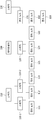
이더넷 기반의 차량 네트워크는 복수의 통신 노드(communication node)들로 구성될 수 있다. 구체적으로, 통신 노드는 게이트웨이(gateway), 스위치(switch)(또는, 브릿지(bridge)), 엔드(end) 노드 등을 의미할 수 있다. 이?, 차량 네트워크에서 복수의 스위치들은 계층적인 형태로 서로 연결될 수 있고, 각 스위치는 복수의 엔드 노드들과 연결될 수 있다. 이와 같은 환경에서, 복수의 스위치들 중 하나인 스위치 1은 복수의 스위치들이 계층적인 형태로 연결되어 있으므로, 복수의 스위치들에 포함된 스위치 2 내지 스위치 4를 통해 연결된 스위치 5에 대한 링크 상태를 진단하기 위해서는 스위치 2 내지 스위치 4의 정상적인 링크 상태가 보장되어야 하는 문제가 있다.An Ethernet-based vehicle network may comprise a plurality of communication nodes. Specifically, the communication node may mean a gateway, a switch (or a bridge), an end node, and the like. In the vehicle network, a plurality of switches may be connected to each other in a hierarchical manner, and each switch may be connected to a plurality of end nodes. In this environment, since the
상기와 같은 문제점을 해결하기 위한 본 발명의 목적은 이더넷 기반의 차량 네트워크의 스위치에서 계층적인 형태로 연결된 복수의 스위치들에 대한 자체적인 진단이 가능한 통신 노드의 동작 방법을 제공하는 데 있다.SUMMARY OF THE INVENTION It is an object of the present invention to provide a method of operating a communication node capable of self-diagnosis of a plurality of switches connected in a hierarchical manner in a switch of an Ethernet-based vehicle network.
상기 목적을 달성하기 위한 본 발명의 일 실시예에 따른 차량 네트워크에서 진단을 위한 통신 노드의 동작 방법은 복수의 스위치(switch)들을 포함하는 차량 네트워크에서 상기 복수의 스위치들 중에서 제1 스위치의 동작 방법으로서, 상기 복수의 스위치들은 버스 라인(bus line)에 의해 연결됨으로써 버스 토폴로지(topology)를 형성하고, 상기 버스 라인을 통해 OBD(on-board diagnostic) 장치로부터 진단 요청 메시지(diagnosis request message)를 수신하는 단계, 상기 진단 요청 메시지에 의해 지시되는 진단 동작을 수행하는 단계 및 상기 진단 동작의 수행 결과를 상기 버스 라인을 통해 상기 OBD 장치에 전송하는 단계를 포함한다.According to an aspect of the present invention, there is provided a method of operating a communication node for diagnosis in a vehicle network, the method comprising: operating the first switch among the plurality of switches in a vehicle network including a plurality of switches Wherein the plurality of switches are connected by a bus line to form a bus topology and receive a diagnosis request message from an on-board diagnostic (OBD) device through the bus line Performing a diagnostic operation indicated by the diagnostic request message, and transmitting a result of performing the diagnostic operation to the OBD device via the bus line.
여기서, 상기 복수의 스위치들은 PWM(pulse width modulation) 방식의 진단을 수행하기 위한 제1 버스 라인 또는 PLC(power line communication) 방식의 진단을 수행하기 위한 제2 버스 라인에 의해 연결될 수 있다.Here, the plurality of switches may be connected by a first bus line for performing a PWM (pulse width modulation) diagnosis or a second bus line for performing a diagnosis of a PLC (power line communication) method.
여기서, 상기 제1 버스 라인은 상기 복수의 스위치들 각각의 컨트롤러 유닛(controller unit) 간을 연결할 수 있다.Here, the first bus line may connect controller units of each of the plurality of switches.
여기서, 상기 진단 동작을 수행하는 단계는 상기 제1 버스 라인으로 연결된 상기 제1 스위치의 컨트롤러 유닛에서 상기 진단 요청 메시지를 수신하는 경우, 상기 컨트롤러 유닛이 상기 진단 동작을 지시하는 지시자가 포함된 제1 메시지를 생성하는 단계, 상기 컨트롤러 유닛이 상기 생성된 제1 메시지를 상기 제1 스위치의 PHY 계층 유닛에 전송하는 단계 및 상기 제1 스위치의 PHY 계층 유닛이 상기 지시자가 지시하는 진단 동작을 수행하는 단계를 더 포함할 수 있다.Here, the performing of the diagnostic operation may include: when receiving the diagnosis request message from the controller unit of the first switch connected to the first bus line, Message, the controller unit transmitting the generated first message to the PHY layer unit of the first switch, and the PHY layer unit of the first switch performing a diagnostic operation indicated by the indicator As shown in FIG.
여기서, 상기 제1 버스 라인으로 연결된 상기 제1 스위치의 컨트롤러 유닛을 통해 수신되는 상기 진단 요청 메시지는 PWM 방식에 기초하여 진단을 수행하기 위한 미리 설정된 주파수로 전송되고, 상기 PWM 방식에 기초한 진단 동작을 지시하는 듀티비(duty ratio)를 포함할 수 있다.Here, the diagnosis request message received through the controller unit of the first switch connected to the first bus line is transmitted at a preset frequency for performing diagnosis based on the PWM method, and the diagnosis operation based on the PWM method is performed And may include a duty ratio that indicates the duty ratio.
여기서, 상기 제2 버스 라인은 상기 복수의 스위치들 각각의 포함된 전력 회로(power circuit) 간을 연결할 수 있다.Here, the second bus line may connect the power circuits included in each of the plurality of switches.
여기서, 상기 진단 동작을 수행하는 단계는 상기 제2 버스 라인으로 연결된 상기 제1 스위치의 전력 회로를 통해 상기 진단 요청 메시지가 수신되는 경우, 상기 전력 회로가 상기 진단 요청 메시지를 상기 제1 스위치의 컨트롤러 유닛에 전송하는 단계, 상기 컨트롤러 유닛이 상기 진단 동작을 지시하는 지시자가 포함된 제1 메시지를 생성하는 단계, 상기 컨트롤러 유닛이 상기 생성된 제1 메시지를 상기 제1 스위치의 PHY 계층 유닛에 전송하는 단계 및 상기 제1 스위치의 PHY 계층 유닛이 상기 지시자가 지시하는 진단 동작을 수행하는 단계를 더 포함할 수 있다.Here, the performing of the diagnostic operation may include: when the diagnosis request message is received through the power circuit of the first switch connected to the second bus line, the power circuit transmits the diagnosis request message to the controller Unit, the controller unit generating a first message including an indicator for instructing the diagnosis operation, and the controller unit transmitting the generated first message to the PHY layer unit of the first switch And a PHY layer unit of the first switch performing a diagnostic operation indicated by the indicator.
여기서, 상기 복수의 스위치들 각각의 식별자는 DIP(duel in-line package) 스위치에 기초하여 설정되고, 상기 진단 요청 메시지는 상기 설정된 제1 스위치의 식별자(identifier)를 포함할 수 있다.Here, the identifier of each of the plurality of switches is set based on a duel in-line package (DIP) switch, and the diagnostic request message may include an identifier of the set first switch.
여기서, 상기 진단 요청 메시지는 상기 복수의 스위치들의 리셋(reset), 상기 제1 스위치에 포함된 PHY 계층 유닛의 리셋, 상기 제1 스위치에 포함된 PHY 계층 유닛의 수신 확인 및 상기 제1 스위치에 포함된 PHY 계층 유닛의 발신 확인 중 적어도 하나의 동작을 지시하는 지시자를 포함할 수 있다.Here, the diagnosis request message may include a reset of the plurality of switches, a reset of the PHY layer unit included in the first switch, an acknowledgment of the PHY layer unit included in the first switch, And an indicator for indicating at least one operation of the origination confirmation of the PHY layer unit.
상기 목적을 달성하기 위한 본 발명의 다른 실시예에 따른 차량 네트워크에서 진단을 위한 통신 노드의 동작 방법은 차량 네트워크에 포함된 복수의 스위치(switch)들을 진단하기 위해 OBD(on-board diagnostic) 장치에 수행되는 동작 방법으로서, 상기 복수의 스위치들은 버스 라인(bus line)에 의해 연결됨으로써 버스 토폴로지(topology)를 형성하고, 상기 복수의 스위치들 중 적어도 하나의 스위치를 진단하기 위한 진단 요청 메시지(diagnosis request message)를 생성하는 단계, 상기 버스 라인을 통해 상기 생성된 진단 요청 메시지를 상기 적어도 하나의 스위치로 전송하는 단계, 상기 적어도 하나의 스위치로부터 상기 적어도 하나의 스위치의 진단 결과에 대한 정보가 포함된 진단 응답 메시지(diagnosis response message)를 수신하는 단계 및 상기 진단 응답 메시지에 기초하여 상기 적어도 하나의 스위치에 대한 진단을 수행하는 단계를 포함한다.According to another aspect of the present invention, there is provided a method of operating a communication node for diagnosis in a vehicle network, the method comprising: providing an OBD (on-board diagnostic) device for diagnosing a plurality of switches included in a vehicle network Wherein the plurality of switches are connected by a bus line to form a bus topology and a diagnostic request message for diagnosing at least one switch of the plurality of switches, message, sending the generated diagnostic request message to the at least one switch via the bus line, diagnosing the at least one switch with information about the diagnostic result of the at least one switch, Receiving a diagnosis response message, and based on the diagnostic response message And performing diagnostics on the at least one switch.
여기서, 상기 OBD 장치의 동작 방법은 상기 차량 네트워크의 이더넷(ethernet) 경로를 통해 진단 응답 메시지를 수신하지 못한 경우, 수행될 수 있다.Here, the operation method of the OBD device may be performed when the diagnostic response message is not received through the ethernet path of the vehicle network.
여기서, 상기 진단 요청 메시지는 상기 적어도 하나의 스위치에 포함된 PHY 계층 유닛의 리셋(reset), 상기 적어도 하나의 스위치에 포함된 PHY 계층 유닛의 수신 확인 및 상기 적어도 하나의 스위치에 포함된 PHY 계층 유닛의 발신 확인 중 적어도 하나의 동작을 지시하는 지시자를 포함할 수 있다.Here, the diagnostic request message includes a reset of a PHY layer unit included in the at least one switch, an acknowledgment of a PHY layer unit included in the at least one switch, and a PHY layer unit included in the at least one switch. And an indicator for indicating at least one operation of the outgoing call confirmation of the mobile terminal.
여기서, 상기 복수의 스위치들 각각의 식별자는 DIP(duel in-line package) 스위치에 기초하여 설정되고, 상기 진단 요청 메시지는 상기 설정된 적어도 하나의 스위치의 식별자(identifier)를 포함할 수 있다.Here, the identifier of each of the plurality of switches is set based on a duel in-line package (DIP) switch, and the diagnostic request message may include an identifier of the set at least one switch.
여기서, 상기 복수의 스위치들은 PWM(pulse width modulation) 방식의 진단을 수행하기 위한 제1 버스 라인 및 PLC(power line communication) 방식의 진단을 수행하기 위한 제2 버스 라인에 의해 연결될 수 있다.Here, the plurality of switches may be connected by a first bus line for performing a PWM (pulse width modulation) diagnosis and a second bus line for performing a diagnosis of a power line communication (PLC) method.
여기서, 상기 제1 버스 라인은 상기 복수의 스위치들 각각의 컨트롤러 유닛(controller unit) 간을 연결할 수 있다.Here, the first bus line may connect controller units of each of the plurality of switches.
여기서, 상기 제2 버스 라인은 상기 복수의 스위치들 각각의 포함된 전력 회로(power circuit) 간을 연결할 수 있다.Here, the second bus line may connect the power circuits included in each of the plurality of switches.
상기 목적을 달성하기 위한 본 발명의 또 다른 실시예에 따른 차량 네트워크에서 진단을 위한 통신 노드의 동작 방법을 수행하는 제1 통신 노드는 차량 네트워크에서 버스 라인(bus line)에 의해 연결됨으로써 버스 토폴로지(topology)를 형성하는 복수의 스위치(switch)들 중 제1 스위치로서, 컨트롤러 유닛(controller unit), 적어도 하나의 PHY 계층 유닛 및 상기 제1 스위치에 전력을 공급하는 전력 회로(power circuit)를 포함하며, 상기 컨트롤러 유닛은 상기 버스 라인과 연결된 OBD(on-board) 장치로부터 진단 요청 메시지(diagnosis request message)를 수신하고, 상기 컨트롤러 유닛은 상기 진단 요청 메시지에 의해 지시되는 진단 동작을 확인하고, 상기 컨트롤러 유닛은 상기 진단 동작의 수행을 요청하는 지시자를 상기 적어도 하나의 PHY 계층 유닛에 전송하고, 상기 지시자를 수신한 상기 적어도 하나의 PHY 계층 유닛은 상기 지시자에 의해 요청되는 상기 진단 동작을 수행한다.According to another aspect of the present invention, there is provided a first communication node for performing a method of operating a communication node for diagnosis in a vehicle network, the first communication node being connected by a bus line in a vehicle network, wherein the first switch comprises a controller unit, at least one PHY layer unit and a power circuit for supplying power to the first switch, , The controller unit receives a diagnosis request message from an on-board (OBD) device connected to the bus line, the controller unit confirms the diagnostic operation indicated by the diagnostic request message, The unit sends an indicator to the at least one PHY layer unit requesting to perform the diagnostic operation, Shinhan the at least one PHY layer unit performs the diagnosis operation is requested by the indicator.
여기서, 상기 복수의 스위치들은 PWM(pulse width modulation) 방식의 진단을 수행하기 위한 제1 버스 라인 또는 PLC(power line communication) 방식의 진단을 수행하기 위한 제2 버스 라인에 의해 연결될 수 있다.Here, the plurality of switches may be connected by a first bus line for performing a PWM (pulse width modulation) diagnosis or a second bus line for performing a diagnosis of a PLC (power line communication) method.
여기서, 상기 제1 버스 라인은 상기 제1 스위치의 컨트롤러 유닛과 연결되고, 상기 제2 버스 라인은 상기 제1 스위치의 전력 회로와 연결될 수 있다.Here, the first bus line may be connected to the controller unit of the first switch, and the second bus line may be connected to the power circuit of the first switch.
여기서, 상기 진단 요청 메시지는 상기 적어도 하나의 PHY 계층 유닛의 리셋(reset), 상기 적어도 하나의 PHY 계층 유닛의 수신 확인 및 상기 적어도 하나의 PHY 계층 유닛의 발신 확인 중 적어도 하나의 동작을 지시할 수 있다.Here, the diagnostic request message may indicate at least one of resetting of the at least one PHY layer unit, acknowledgment of the at least one PHY layer unit, and acknowledging of the at least one PHY layer unit have.
본 발명에 의하면, 차량 네트워크를 구성하는 복수의 통신 노드들에 대한 고장 상태를 용이하게 판단함으로써, 고장된 것으로 판단된 통신 노드의 고장을 효율적으로 처리할 수 있는 효과가 있다. 또한, 차량 네트워크에서 복수의 통신 노드들의 고장 상태를 판단 가능한 복수개의 링크들(예를 들어, 진단을 위한 제1 링크 및 전력을 공급하는 제2 링크)을 활용함으로써, 통신 노드의 진단을 위해 사용되는 링크를 선택적으로 사용할 수 있는 효과가 있다.According to the present invention, it is possible to efficiently process a failure of a communication node determined as a failure by easily determining a failure state of a plurality of communication nodes constituting a vehicle network. Further, by utilizing a plurality of links (for example, a first link for diagnosis and a second link for supplying power) capable of determining a failure state of a plurality of communication nodes in the vehicle network, The link can be selectively used.
도 1은 차량 네트워크의 토폴로지에 대한 일 실시예를 도시한 블록도이다.
도 2는 차량 네트워크를 구성하는 통신 노드의 구조에 대한 제1 실시예를 도시한 블록도이다.
도 3은 차량 네트워크를 구성하는 통신 노드의 제2 실시예를 도시한 블록도이다.
도 4는 OBD 장치를 사용하여 차량 네트워크를 진단하는 방법의 일 실시예를 설명하기 위한 블록도이다.
도 5는 OBD 장치를 사용하여 차량 네트워크를 진단하는 방법의 다른 실시예를 설명하기 위한 블록도이다.
도 6은 도 5에 도시된 실시예에 따라 차량 네트워크를 진단하는 방법 방법을 설명하기 위한 블록도이다.
도 7은 본 발명의 일 실시예에 따른 차량 네트워크에서 진단을 위한 통신 노드의 동작 방법을 수행하는 통신 노드를 도시한 블록도이다.
도 8은 본 발명의 일 실시예에 따른 차량 네트워크에서 진단을 위한 통신 노드의 동작 방법을 도시한 순서도이다.1 is a block diagram illustrating an embodiment of a topology of a vehicle network.
2 is a block diagram showing a first embodiment of the structure of a communication node constituting a vehicle network.
3 is a block diagram showing a second embodiment of a communication node constituting a vehicle network.
4 is a block diagram illustrating an embodiment of a method of diagnosing a vehicle network using an OBD device.
5 is a block diagram for explaining another embodiment of a method of diagnosing a vehicle network using an OBD apparatus.
6 is a block diagram illustrating a method for diagnosing a vehicle network according to the embodiment shown in FIG.
7 is a block diagram illustrating a communication node performing a method of operation of a communication node for diagnosis in a vehicle network, in accordance with an embodiment of the present invention.
8 is a flowchart illustrating a method of operating a communication node for diagnosis in a vehicle network according to an embodiment of the present invention.
본 발명은 다양한 변경을 가할 수 있고 여러 가지 실시예를 가질 수 있는 바, 특정 실시예들을 도면에 예시하고 상세하게 설명하고자 한다. 그러나, 이는 본 발명을 특정한 실시 형태에 대해 한정하려는 것이 아니며, 본 발명의 사상 및 기술 범위에 포함되는 모든 변경, 균등물 내지 대체물을 포함하는 것으로 이해되어야 한다.While the invention is susceptible to various modifications and alternative forms, specific embodiments thereof are shown by way of example in the drawings and will herein be described in detail. It should be understood, however, that the invention is not intended to be limited to the particular embodiments, but includes all modifications, equivalents, and alternatives falling within the spirit and scope of the invention.
제1, 제2 등의 용어는 다양한 구성요소들을 설명하는데 사용될 수 있지만, 상기 구성요소들은 상기 용어들에 의해 한정되어서는 안 된다. 상기 용어들은 하나의 구성요소를 다른 구성요소로부터 구별하는 목적으로만 사용된다. 예를 들어, 본 발명의 권리 범위를 벗어나지 않으면서 제1 구성요소는 제2 구성요소로 명명될 수 있고, 유사하게 제2 구성요소도 제1 구성요소로 명명될 수 있다. 및/또는 이라는 용어는 복수의 관련된 기재된 항목들의 조합 또는 복수의 관련된 기재된 항목들 중의 어느 항목을 포함한다.The terms first, second, etc. may be used to describe various components, but the components should not be limited by the terms. The terms are used only for the purpose of distinguishing one component from another. For example, without departing from the scope of the present invention, the first component may be referred to as a second component, and similarly, the second component may also be referred to as a first component. And / or < / RTI > includes any combination of a plurality of related listed items or any of a plurality of related listed items.
어떤 구성요소가 다른 구성요소에 "연결되어" 있다거나 "접속되어" 있다고 언급된 때에는, 그 다른 구성요소에 직접적으로 연결되어 있거나 또는 접속되어 있을 수도 있지만, 중간에 다른 구성요소가 존재할 수도 있다고 이해되어야 할 것이다. 반면에, 어떤 구성요소가 다른 구성요소에 "직접 연결되어" 있다거나 "직접 접속되어" 있다고 언급된 때에는, 중간에 다른 구성요소가 존재하지 않는 것으로 이해되어야 할 것이다.It is to be understood that when an element is referred to as being "connected" or "connected" to another element, it may be directly connected or connected to the other element, . On the other hand, when an element is referred to as being "directly connected" or "directly connected" to another element, it should be understood that there are no other elements in between.
본 출원에서 사용한 용어는 단지 특정한 실시예를 설명하기 위해 사용된 것으로, 본 발명을 한정하려는 의도가 아니다. 단수의 표현은 문맥상 명백하게 다르게 뜻하지 않는 한, 복수의 표현을 포함한다. 본 출원에서, "포함하다" 또는 "가지다" 등의 용어는 명세서상에 기재된 특징, 숫자, 단계, 동작, 구성요소, 부품 또는 이들을 조합한 것이 존재함을 지정하려는 것이지, 하나 또는 그 이상의 다른 특징들이나 숫자, 단계, 동작, 구성요소, 부품 또는 이들을 조합한 것들의 존재 또는 부가 가능성을 미리 배제하지 않는 것으로 이해되어야 한다.The terminology used in this application is used only to describe a specific embodiment and is not intended to limit the invention. The singular expressions include plural expressions unless the context clearly dictates otherwise. In the present application, the terms "comprises" or "having" and the like are used to specify that there is a feature, a number, a step, an operation, an element, a component or a combination thereof described in the specification, But do not preclude the presence or addition of one or more other features, integers, steps, operations, elements, components, or combinations thereof.
다르게 정의되지 않는 한, 기술적이거나 과학적인 용어를 포함해서 여기서 사용되는 모든 용어들은 본 발명이 속하는 기술 분야에서 통상의 지식을 가진 자에 의해 일반적으로 이해되는 것과 동일한 의미를 가지고 있다. 일반적으로 사용되는 사전에 정의되어 있는 것과 같은 용어들은 관련 기술의 문맥 상 가지는 의미와 일치하는 의미를 가진 것으로 해석되어야 하며, 본 출원에서 명백하게 정의하지 않는 한, 이상적이거나 과도하게 형식적인 의미로 해석되지 않는다.Unless defined otherwise, all terms used herein, including technical or scientific terms, have the same meaning as commonly understood by one of ordinary skill in the art to which this invention belongs. Terms such as those defined in commonly used dictionaries should be interpreted as having a meaning consistent with the meaning in the context of the relevant art and are to be interpreted in an ideal or overly formal sense unless explicitly defined in the present application Do not.
이하, 첨부한 도면들을 참조하여, 본 발명의 바람직한 실시예를 보다 상세하게 설명하고자 한다. 본 발명을 설명함에 있어 전체적인 이해를 용이하게 하기 위하여 도면상의 동일한 구성요소에 대해서는 동일한 참조부호를 사용하고 동일한 구성요소에 대해서 중복된 설명은 생략한다.Hereinafter, preferred embodiments of the present invention will be described in detail with reference to the accompanying drawings. In order to facilitate the understanding of the present invention, the same reference numerals are used for the same constituent elements in the drawings and redundant explanations for the same constituent elements are omitted.
도 1은 차량 네트워크의 토폴로지(network topology)의 일 실시예를 도시한 블록도이다.1 is a block diagram illustrating one embodiment of a network topology of a vehicle network.
도 1을 참조하면, 차량 네트워크를 구성하는 통신 노드(communication node)는 게이트웨이(gateway), 스위치(switch)(또는, 브릿지(bridge)) 또는 엔드 노드(end node) 등을 의미할 수 있다. 게이트웨이(100)는 적어도 하나의 스위치(110, 110-1, 110-2, 120, 130)와 연결될 수 있으며, 서로 다른 네트워크를 연결할 수 있다. 예를 들어, 게이트웨이(100)는 CAN(controller area network)(또는, 플렉스레이(FlexRay), MOST(media oriented system transport), LIN(local interconnect network) 등) 프로토콜(protocol)을 지원하는 스위치와 이더넷(ethernet) 프로토콜을 지원하는 스위치 간을 연결할 수 있다. 스위치들(110, 110-1, 110-2, 120, 130) 각각은 적어도 하나의 엔드 노드(111, 112, 113, 121, 122, 123, 131, 132, 133)와 연결될 수 있다. 스위치들(110, 110-1, 110-2, 120, 130) 각각은 엔드 노드(111, 112, 113, 121, 122, 123, 131, 132, 133)를 상호 연결할 수 있고, 자신과 연결된 엔드 노드(111, 112, 113, 121, 122, 123, 131, 132, 133)를 제어할 수 있다.1, a communication node constituting a vehicle network may refer to a gateway, a switch (or a bridge), an end node, or the like. The
엔드 노드(111, 112, 113, 121, 122, 123, 131, 132, 133)는 차량에 포함된 각종 장치를 제어하는 ECU(electronic control unit)를 의미할 수 있다. 예를 들어, 엔드 노드(111, 112, 113, 121, 122, 123, 131, 132, 133)는 인포테인먼트(infotainment) 장치(예를 들어, 디스플레이(display) 장치, 내비게이션(navigation) 장치, 어라운드 뷰 모니터링(around view monitoring) 장치) 등을 구성하는 ECU를 의미할 수 있다.The
한편, 차량 네트워크를 구성하는 통신 노드들(즉, 게이트웨이, 스위치, 엔드 노드 등)은 스타(star) 토폴로지, 버스(bus) 토폴로지, 링(ring) 토폴로지, 트리(tree) 토폴로지, 메쉬(mesh) 토폴로지 등으로 연결될 수 있다. 또한, 차량 네트워크를 구성하는 통신 노드들 각각은 CAN 프로토콜, 플렉스레이 프로토콜, MOST 프로토콜, LIN 프로토콜, 이더넷 프로토콜 등을 지원할 수 있다. 본 발명에 따른 실시예들은 앞서 설명된 네트워크 토폴로지에 적용될 수 있으며, 본 발명에 따른 실시예들이 적용되는 네트워크 토폴로지는 이에 한정되지 않고 다양하게 구성될 수 있다.The communication nodes (i.e., gateways, switches, end nodes, etc.) that constitute the vehicle network may be a star topology, a bus topology, a ring topology, a tree topology, Topology, and so on. Further, each of the communication nodes constituting the vehicle network may support the CAN protocol, the FlexRay protocol, the MOST protocol, the LIN protocol, the Ethernet protocol, and the like. Embodiments according to the present invention can be applied to the network topology described above, and the network topology to which the embodiments according to the present invention are applied is not limited to this, and can be variously configured.
도 2는 차량 네트워크를 구성하는 통신 노드의 구조에 대한 일 실시예를 도시한 블록도이다.2 is a block diagram showing an embodiment of a structure of a communication node constituting a vehicle network.
도 2를 참조하면, 차량 네트워크를 구성하는 통신 노드(200)는 PHY 계층 유닛(physical layer unit)(210) 및 컨트롤러(controller) 유닛(220)을 포함할 수 있다. 또한, 통신 노드(200)는 파워(power)를 공급하는 레귤레이터(regulator)(미도시)를 더 포함할 수 있다. 이때, 컨트롤러 유닛(220)은 MAC(medium access control) 계층을 포함하여 구현될 수 있다. PHY 계층 유닛(210)은 다른 통신 노드로부터 신호를 수신할 수 있거나, 다른 통신 노드로 신호를 전송할 수 있다. 컨트롤러 유닛(220)은 PHY 계층 유닛(210)을 제어할 수 있고, 다양한 기능들(예를 들어, 인포테인먼트 기능 등)을 수행할 수 있다. PHY 계층 유닛(210)과 컨트롤러 유닛(220)은 하나의 SoC(System on Chip)로 구현될 수도 있고, 별도의 칩으로 구성될 수도 있다.Referring to FIG. 2, a
PHY 계층 유닛(210)과 컨트롤러 유닛(220)은 매체 독립 인터페이스(media independent interface, MII)(230)를 통해 연결될 수 있다. MII(230)는 IEEE 802.3에 규정된 인터페이스를 의미할 수 있으며, PHY 계층 유닛(210)과 컨트롤러 유닛(220) 간의 데이터 인터페이스 및 관리 인터페이스로 구성될 수 있다. MII(230) 대신에 RMII(reduced MII), GMII(gigabit MII), RGMII(reduced GMII), SGMII(serial GMII), XGMII(10 GMII) 중 하나의 인터페이스가 사용될 수 있다. 데이터 인터페이스는 전송 채널(channel) 및 수신 채널을 포함할 수 있으며, 채널들 각각은 독립적인 클럭(clock), 데이터 및 제어 신호를 가질 수 있다. 관리 인터페이스는 2-신호 인터페이스로 구성될 수 있으며, 하나는 클럭을 위한 신호이고 다른 하나는 데이터를 위한 신호일 수 있다.The
PHY 계층 유닛(210)은 PHY 계층 인터페이스 유닛(211), PHY 계층 프로세서(processor)(212) 및 PHY 계층 메모리(memory)(213) 등을 포함할 수 있다. PHY 계층 유닛(210)의 구성은 이에 한정되지 않으며, PHY 계층 유닛(210)은 다양하게 구성될 수 있다. PHY 계층 인터페이스 유닛(211)은 컨트롤러 유닛(220)으로부터 수신된 신호를 PHY 계층 프로세서(212)로 전송할 수 있고, PHY 계층 프로세서(212)로부터 수신된 신호를 컨트롤러 유닛(220)에 전송할 수 있다. PHY 계층 프로세서(212)는 PHY 계층 인터페이스 유닛(211) 및 PHY 계층 메모리(213) 각각의 동작을 제어할 수 있다. PHY 계층 프로세서(212)는 전송할 신호의 변조 또는 수신된 신호의 복조를 수행할 수 있다. PHY 계층 프로세서(212)는 신호를 입력 또는 출력하도록 PHY 계층 메모리(213)를 제어할 수 있다. PHY 계층 메모리(213)는 수신된 신호를 저장할 수 있고, PHY 계층 프로세서(212)의 요청에 따라 저장된 신호를 출력할 수 있다.The
컨트롤러 유닛(220)은 MII(230)를 통해 PHY 계층 유닛(210)에 대한 모니터링 및 제어를 수행할 수 있다. 컨트롤러 유닛(220)은 컨트롤러 인터페이스 유닛(221), 컨트롤러 프로세서(222), 주 메모리(223) 및 보조 메모리(224) 등을 포함할 수 있다. 컨트롤러 유닛(220)의 구성은 이에 한정되지 않으며, 컨트롤러 유닛(220)은 다양하게 구성될 수 있다. 컨트롤러 인터페이스 유닛(221)은 PHY 계층 유닛(210)(즉, PHY 계층 인터페이스 유닛(211)) 또는 상위 계층(미도시)으로부터 신호를 수신할 수 있고, 수신된 신호를 컨트롤러 프로세서(222)에 전송할 수 있고, 컨트롤러 프로세서(222)로부터 수신된 신호를 PHY 계층 유닛(210) 또는 상위 계층에 전송할 수 있다. 컨트롤러 프로세서(222)는 컨트롤러 인터페이스 유닛(221), 주 메모리(223) 및 보조 메모리(224)를 제어하기 위한 독립된 메모리 컨트롤 로직(control logic) 또는 통합 메모리 컨트롤 로직을 더 포함할 수 있다. 메모리 컨트롤 로직은 주 메모리(223) 및 보조 메모리(224)에 포함되어 구현될 수도 있으며, 또는 컨트롤러 프로세서(222)에 포함되어 구현될 수도 있다.The
주 메모리(223) 및 보조 메모리(224) 각각은 컨트롤러 프로세서(222)에 의해 처리된 신호를 저장할 수 있고, 컨트롤러 프로세서(222)의 요청에 따라 저장된 신호를 출력할 수 있다. 주 메모리(223)는 컨트롤러 프로세서(222)의 동작을 위해 필요한 데이터를 일시 저장하는 휘발성 메모리(예를 들어, RAM(random access memory) 등)를 의미할 수 있다. 보조 메모리(224)는 운영체제 코드(operating system code)(예를 들어, 커널(kernel) 및 디바이스 드라이버(device driver))와 컨트롤러 프로세서(220)의 기능을 수행하기 위한 응용 프로그램(application program) 코드 등이 저장되는 비휘발성 메모리를 의미할 수 있다. 비휘발성 메모리로 빠른 처리 속도를 가지는 플래쉬 메모리(flash memory)가 사용될 수 있고, 또는 대용량의 데이터 저장을 위한 하드 디스크 드라이브(hard disc drive, HDD), CD-ROM(compact disc-read only memory) 등이 사용될 수 있다. 컨트롤러 프로세서(222)는 통상적으로 적어도 하나의 프로세싱 코어(core)를 포함하는 로직 회로로 구성될 수 있다. 컨트롤러 프로세서(222)로 ARM(Advanced RISC Machines Ltd.) 계열의 코어, 아톰(atom) 계열의 코어 등이 사용될 수 있다.Each of the
도 3은 차량 네트워크를 구성하는 통신 노드의 제2 실시예를 도시한 블록도이다.3 is a block diagram showing a second embodiment of a communication node constituting a vehicle network.
도 3을 참조하면, 통신 노드(200)는 PHY 계층 유닛(210), 컨트롤러 유닛(220), 전력 회로(power circuit)(240), OR 게이트(gate)(250), 전력 조절기(power regulator)(260) 등을 포함할 수 있다. 도 3에 도시된 PHY 계층 유닛(210) 및 컨트롤러 유닛(220) 각각은 도 2에 도시된 PHY 계층 유닛(210) 및 컨트롤러 유닛(220)과 동일 또는 유사할 수 있다.3, the
PHY 계층 유닛(210)은 복수의 핀(pin)들(예를 들어, P11, P12, P13, P14, P15)을 포함할 수 있다. PHY 계층 유닛(210)은 P11을 통해 전력 공급을 지시하는 신호, 전력 오프를 지시하는 신호 등을 출력할 수 있다. 예를 들어, PHY 계층 유닛(210)의 P11을 통해 출력되는 하이(high) 신호는 전력 공급을 지시할 수 있고, PHY 계층 유닛(210)의 P11을 통해 출력되는 로우(low) 신호는 전력 오프를 지시할 수 있다. PHY 계층 유닛(210)의 P11은 INH(inhibit) 핀을 의미할 수 있다.
또는, PHY 계층 유닛(210)은 P11을 통해 인터럽트(interrupt) 신호를 출력할 수 있다. 예를 들어, PHY 계층 유닛(210)의 P11을 통해 출력되는 하이 신호는 인터럽트 신호를 의미할 수 있고, 인터럽트 신호는 컨트롤러 유닛(220)의 P22에서 수신될 수 있다. 인터럽트 신호는 슬립 모드에서 노멀 모드로 천이할 것을 지시할 수 있다. 여기서, P11은 인터럽트 핀을 의미할 수 있다.Alternatively, the
PHY 계층 유닛(210)의 P12를 통해 전력 회로(240)로부터 전력이 공급될 수 있다. PHY 계층 유닛(210)은 P13을 통해 슬립 모드에서 노멀 모드로의 천이를 지시하는 신호, 노멀 모드에서 슬립 모드로의 천이를 지시하는 신호 등을 수신할 수 있다. 예를 들어, PHY 계층 유닛(210)의 P13을 통해 입력된 하이 신호는 슬립 모드에서 노멀 모드로의 천이를 지시할 수 있고, PHY 계층 유닛(210)의 P13을 통해 입력된 로우 신호는 노멀 모드에서 슬립 모드로의 천이를 지시할 수 있다. PHY 계층 유닛(210)의 P13은 EN(enable) 핀을 의미할 수 있다.Power can be supplied from the
PHY 계층 유닛(210)의 P14는 xMII를 위해 사용될 수 있고, PHY 계층 유닛(210)의 P15는 MDIO(management data input/output) 인터페이스를 위해 사용될 수 있다. 예를 들어, PHY 계층 유닛(210)은 P14와 P15를 사용하여 컨트롤러 유닛(220)과 신호(예를 들어, 이더넷 관련 신호)를 송수신할 수 있다. PHY 계층 유닛(210)에 포함된 복수의 핀들 각각의 설정은 앞서 설명된 내용에 한정되지 않으며, PHY 계층 유닛(210)에 포함된 복수의 핀들 각각은 다양하게 설정될 수 있다.P14 of
컨트롤러 유닛(220)은 복수의 핀들(예를 들어, P21, P22, P23, P24, P25, P26)을 포함할 수 있다. 컨트롤러 유닛(220)의 P21를 통해 전력 회로(240)로부터 전력이 공급될 수 있다. 컨트롤러 유닛(220)은 P22를 통해 인터럽트(interrupt) 신호를 수신할 수 있다. 예를 들어, 컨트롤러 유닛(220)의 P22를 통해 입력된 하이 신호는 인터럽트 신호를 의미할 수 있다. 컨트롤러 유닛(220)은 인터럽트 신호를 수신한 경우 슬립 모드에서 노멀 모드로 천이할 수 있다. 컨트롤러 유닛(220)의 P22는 인터럽트 핀을 의미할 수 있다.The
컨트롤러 유닛(220)은 P23을 통해 슬립 모드에서 노멀 모드로의 천이를 지시하는 신호, 노멀 모드에서 슬립 모드로의 천이를 지시하는 신호 등을 출력할 수 있다. 예를 들어, 컨트롤러 유닛(220)의 P23을 통해 출력된 하이 신호는 슬립 모드에서 노멀 모드로의 천이를 지시할 수 있고, 컨트롤러 유닛(220)의 P23을 통해 출력된 로우 신호는 노멀 모드에서 슬립 모드로의 천이를 지시할 수 있다. 컨트롤러 유닛(220)의 P23은 EN 핀을 의미할 수 있다.The
컨트롤러 유닛(220)의 P24는 xMII를 위해 사용될 수 있고, 컨트롤러 유닛(220)의 P25는 MDIO 인터페이스를 위해 사용될 수 있다. 예를 들어, 컨트롤러 유닛(220)은 P24와 P25를 사용하여 PHY 계층 유닛(210)과 신호(예를 들어, 이더넷 관련 신호)를 송수신할 수 있다. 컨트롤러 유닛(220)은 P26을 통해 로컬(local) 웨이크업 신호(예를 들어, 로컬 이벤트(event))를 감지할 수 있다. 예를 들어, 컨트롤러 유닛(220)의 P26을 통해 입력된 하이 신호는 로컬 웨이크업 신호를 의미할 수 있다. 컨트롤러 유닛(220)의 P26은 WAKE 핀을 의미할 수 있다. 컨트롤러 유닛(220)에 포함된 복수의 핀들 각각의 설정은 앞서 설명된 내용에 한정되지 않으며, 컨트롤러 유닛(220)에 포함된 복수의 핀들 각각은 다양하게 설정될 수 있다.P24 of the
전력 회로(240)는 복수의 핀들(예를 들어, P31, P32, P33)을 포함할 수 있다. 전력 회로(240)는 P33을 통해 전력 공급을 지시하는 신호, 전력 오프를 지시하는 신호 등을 수신할 수 있다. 예를 들어, 전력 회로(240)의 P33을 통해 입력된 하이 신호는 전력 공급을 지시할 수 있고, 전력 회로(240)의 P33으로부터 입력된 로우 신호는 전력 오프를 지시할 수 있다. 전력 회로(240)는 P33을 통해 입력된 신호에 기초하여 전력을 공급할 수 있다. 예를 들어, 전력 회로(240)는 P31을 통해 컨트롤러 유닛(220)에 전력을 공급할 수 있고, P32을 통해 PHY 계층 유닛(210)에 전력을 공급할 수 있다. 전력 회로(240)에 포함된 복수의 핀들 각각의 설정은 앞서 설명된 내용에 한정되지 않으며, 전력 회로(240)에 포함된 복수의 핀들 각각은 다양하게 설정될 수 있다.
OR 회로(250)는 임의의 개체(예를 들어, 컨트롤러 유닛(220))로부터 제어 신호(예를 들어, 하이 신호 또는 로우 신호)를 수신할 수 있고, PHY 계층 유닛(210)으로부터 신호(예를 들어, 하이 신호 또는 로우 신호)를 수신할 수 있다. OR 회로(250)는 임의의 개체로부터 수신된 제어 신호와 PHY 계층 유닛(210)으로부터 수신된 신호에 대한 OR 연산을 수행할 수 있고, OR 연산의 결과를 출력할 수 있다. 출력된 OR 연산의 결과는 전력 회로(240)의 P33으로 입력될 수 있다.OR
전력 조절기(260)의 입력단은 전력 회로(240)의 P32와 연결될 수 있고, 전력 조절기(260)의 출력단은 PHY 계층 유닛(210)의 P12에 연결될 수 있다. 전력 회로(240)로부터 공급된 전력의 전압이 미리 설정된 임계값(예를 들어, 3.3V)을 초과하는 경우, 전력 조절기(260)는 공급된 전력의 전압을 미리 설정된 임계값 이하로 조절할 수 있고, 조절된 전압을 가지는 전력을 PHY 계층 유닛(210)에 공급할 수 있다.The input of
아래에서는, 차량 네트워크에 속하는 통신 노드와 이에 대응하는 상대(counterpart) 통신 노드에서 수행되는 방법이 설명될 것이다. 이하에서, 제1 통신 노드에서 수행되는 방법(예를 들어, 신호의 전송 또는 수신)이 설명되는 경우에도 이에 대응하는 제2 통신 노드는 제1 통신 노드에서 수행되는 방법과 상응하는 방법(예를 들어, 신호의 수신 또는 전송)을 수행할 수 있다. 즉, 제1 통신 노드의 동작이 설명된 경우에 이에 대응하는 제2 통신 노드는 제1 통신 노드의 동작과 상응하는 동작을 수행할 수 있다. 반대로, 제2 통신 노드의 동작이 설명된 경우에 이에 대응하는 제1 통신 노드는 스위치의 동작과 상응하는 동작을 수행할 수 있다.Hereinafter, a method performed in a communication node belonging to a vehicle network and a corresponding counterpart communication node will be described. Hereinafter, even when a method (e.g., transmission or reception of a signal) to be performed at the first communication node is described, the corresponding second communication node can perform a method corresponding to the method performed at the first communication node For example, receiving or transmitting a signal). That is, when the operation of the first communication node is described, the corresponding second communication node can perform an operation corresponding to the operation of the first communication node. Conversely, when the operation of the second communication node is described, the corresponding first communication node can perform the operation corresponding to the operation of the switch.
도 4은 OBD(on-board diagnostic) 장치를 사용하여 차량 네트워크를 진단하는 방법의 일 실시예를 설명하기 위한 블록도이다.4 is a block diagram illustrating an embodiment of a method of diagnosing a vehicle network using an on-board diagnostic (OBD) device.
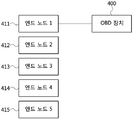
도 4를 참조하면, 엔드 노드들(411, 412, 413, 414, 415)은 도 1을 참조하여 설명된 차량 네트워크를 구성할 수 있고, 이더넷 프로토콜을 지원할 수 있다. 엔드 노드들(411, 412, 413, 414, 415) 각각은 도 2를 참조하여 설명된 통신 노드(200)를 의미할 수 있다. 엔드 노드들(411, 412, 413, 414, 415)은 동일한 스위치에 연결될 수 있고, 또는 서로 다른 스위치에 연결될 수 있다. 엔드 노드들(411, 412, 413, 414, 415) 각각의 상태(즉, 정상 상태 또는 고장(fault) 상태) 및 엔드 노드들(411, 412, 413, 414, 415) 각각이 연결된 채널(또는, 포트(port))의 상태를 진단하기 위해, 엔드 노드들(411, 412, 413, 414, 415) 각각은 OBD 장치(400)와 일대일 형태로 연결되어야 한다. 즉, 엔드 노드 1(411)의 상태 및 엔드 노드 1(411)이 연결된 채널의 상태를 진단하기 위해, OBD 장치(400)는 물리적으로 엔드 노드 1(411)와 일대일 형태로 연결되어야 한다.4, the
OBD 장치(400)와 엔드 노드 1(411)이 일대일 형태로 연결된 경우, OBD 장치(400)는 진단 요청 메시지(diagnosis request message)를 생성할 수 있고, 생성된 진단 요청 메시지를 엔드 노드 1(411)에 전송할 수 있다. 엔드 노드 1(411)은 OBD 장치(400)로부터 진단 요청 메시지를 수신한 경우 진단 요청 메시지에 대한 응답인 진단 응답 메시지(diagnosis response message)를 생성할 수 있고, 생성된 진단 응답 메시지를 OBD 장치(400)에 전송할 수 있다. 또는, 엔드 노드 1(411)는 OBD 장치(400)로부터 진단 요청 메시지를 수신한 경우 진단 요청 메시지에 대한 응답인 ACK(acknowledgement) 메시지를 OBD 장치(400)에 전송할 수 있다. OBD 장치(400)는 진단 요청 메시지의 전송 종료 시점부터 미리 정의된 시간 내에 엔드 노드 1(411)로부터 진단 요청 메시지에 대한 응답인 진단 응답 메시지(또는, ACK 메시지)를 수신한 경우 엔드 노드 1(411) 및 엔드 노드 1(411)가 연결된 채널이 정상 상태인 것으로 판단할 수 있다. 반면, OBD 장치(400)는 진단 요청 메시지의 전송 종료 시점부터 미리 정의된 시간 내에 엔드 노드 1(411)로부터 진단 요청 메시지에 대한 응답인 진단 응답 메시지(또는, ACK 메시지)를 수신하지 못한 경우 엔드 노드 1(411) 및 엔드 노드 1(411)가 연결된 채널이 고장 상태인 것으로 판단할 수 있다.When the
OBD 장치(400)는 위와 같은 절차를 나머지 엔드 노드들(412, 413, 414, 415)과 수행함으로써 엔드 노드들(412, 413, 414, 415) 각각에 대한 상태를 판단할 수 있다. 한편, 차량 네트워크는 매우 많은 수의 엔드 노드들로 구성될 수 있으며, 차량 네트워크를 구성하는 모든 엔드 노드들 각각의 상태를 판단하기 위해, OBD 장치(400)와 엔드 노드를 물리적으로 일대일 형태로 연결하는 절차 및 OBD 장치(400)와 엔드 노드 간의 메시지 교환 절차는 차량 네트워크를 구성하는 모드 엔드 노드들 각각에 대해 수행되어야 한다. 이 경우, 차량 네트워크를 구성하는 모든 엔드 노드들 각각의 상태를 판단하기 위해 많은 시간이 소요된다.The
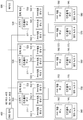
도 5는 OBD 장치를 사용하여 차량 네트워크를 진단하는 방법의 다른 실시예들을 설명하기 위한 블록도이고, 도 6은 도 5에 도시된 실시예에 따라 차량 네트워크를 진단하는 방법 방법을 설명하기 위한 블록도이다.5 is a block diagram for explaining another embodiment of a method for diagnosing a vehicle network using an OBD apparatus, FIG. 6 is a block diagram for explaining a method for diagnosing a vehicle network according to the embodiment shown in FIG. 5, .
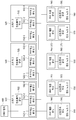
도 5 및 도 6을 참조하면, 차량 네트워크는 OBD 장치(400), 스위치 1(510), 스위치 2(520), 스위치 3(530), 엔드 노드 1(540), 엔드 노드 2(550), 엔드 노드 3(560), 엔드 노드 4(570), 엔드 노드 5(580) 등을 포함할 수 있다. 스위치들(510, 520, 530)은 도 1에 도시된 스위치와 동일 또는 유사한 기능들을 수행할 수 있고, 엔드 노드들(540, 550, 560, 570, 580)은 도 1에 도시된 엔드 노드와 동일 또는 유사한 기능을 수행할 수 있다. 스위치들(510, 520, 530) 및 엔드 노드들(540, 550, 560, 570, 580) 각각은 도 2 내지 4에 도시된 통신 노드와 동일 또는 유사하게 구성될 수 있다.5 and 6, the vehicle network includes an
예를 들어, 스위치 1(510)은 컨트롤러 유닛(511), PHY 계층 유닛 1(512-1), PHY 계층 유닛 2(512-2), PHY 계층 유닛 3(512-3) 등을 포함할 수 있고, 스위치 1(510)에 포함된 컨트롤러 유닛(511) 및 PHY 계층 유닛들(512-1, 512-2, 512-3) 각각은 도 2 및 도 3에 도시된 컨트롤러 유닛(220) 및 PHY 계층 유닛(210)과 동일 또는 유사할 수 있다. 스위치 2(520)는 컨트롤러 유닛(521), PHY 계층 유닛 1(522-1), PHY 계층 유닛 2(522-2), PHY 계층 유닛 3(522-3) 등을 포함할 수 있고, 스위치 2(520)에 포함된 컨트롤러 유닛(521) 및 PHY 계층 유닛들(522-1, 522-2, 522-3) 각각은 도 2 및 도 3에 도시된 컨트롤러 유닛(220) 및 PHY 계층 유닛(210)과 동일 또는 유사할 수 있다. 스위치 3(530)은 컨트롤러 유닛(531), PHY 계층 유닛 1(532-1), PHY 계층 유닛 2(532-2), PHY 계층 유닛 3(532-3) 등을 포함할 수 있고, 스위치 3(530)에 포함된 컨트롤러 유닛(531) 및 PHY 계층 유닛들(532-1, 532-2, 532-3) 각각은 도 2 및 도 3에 도시된 컨트롤러 유닛(220) 및 PHY 계층 유닛(210)과 동일 또는 유사할 수 있다. 엔드 노드들(540, 550, 560, 570, 580) 각각은 컨트롤러 유닛들(541, 551, 561, 571, 581), PHY 계층 유닛들(542, 552, 562, 572, 582) 등을 포함할 수 있고, 엔드 노드들(540, 550, 560, 570, 580)에 포함된 컨트롤러 유닛들(541, 551, 561, 571, 851) 및 PHY 계층 유닛들(542, 552, 562, 572, 582) 각각은 도 2 및 도 3에 도시된 컨트롤러 유닛(220) 및 PHY 계층 유닛(210)과 동일 또는 유사할 수 있다.For example,
OBD 장치(400)는 스위치들(510, 520, 530) 중 하나의 스위치(예를 들어, 스위치 1(510)의 컨트롤러 유닛(511))와 연결될 수 있다. 스위치 1(510)은 컨트롤러 유닛(511)을 통해 OBD 장치(400)와 연결될 수 있고, PHY 계층 유닛 1(512-1)을 통해 엔드 노드 1(540)(예를 들어, 엔드 노드 1(540)의 PHY 계층 유닛(542))과 연결될 수 있고, PHY 계층 유닛 2(512-2)를 통해 엔드 노드 2(550)(예를 들어, 엔드 노드 2(550)의 PHY 계층 유닛(552))와 연결될 수 있고, PHY 계층 유닛 3(512-3)을 통해 스위치 2(520)(예를 들어, 스위치 2(520)의 PHY 계층 유닛 1(522-1))과 연결될 수 있다. 스위치 1(510)과 스위치 2(520) 간의 통신은 MII, RMII, GMII, RGMII, SGMII 및 XGMII 중에서 하나의 인터페이스를 사용하여 수행될 수 있다. 스위치 2(520)는 PHY 계층 유닛 1(522-1)을 통해 스위치 1(510)(예를 들어, 스위치 1(510)의 PHY 계층 유닛 3(512-3))과 연결될 수 있고, PHY 계층 유닛 2(522-2)를 통해 엔드 노드 3(560)(예를 들어, 엔드 노드 3(560)의 PHY 계층 유닛(562))과 연결될 수 있고, PHY 계층 유닛 3(522-3)을 통해 스위치 3(530)(예를 들어, 스위치 3(530)의 PHY 계층 유닛 1(532-1))과 연결될 수 있다. 스위치 2(520)와 스위치 3(530) 간의 통신은 MII, RMII, GMII, RGMII, SGMII 및 XGMII 중에서 하나의 인터페이스를 사용하여 수행될 수 있다. 스위치 3(530)은 PHY 계층 유닛 1(532-1)을 통해 스위치 2(520)(예를 들어, 스위치 2(520)의 PHY 계층 유닛 3(522-3))와 연결될 수 있고, PHY 계층 유닛 2(532-2)를 통해 엔드 노드 4(570)(예를 들어, 엔드 노드 4(570)의 PHY 계층 유닛(572))와 연결될 수 있고, PHY 계층 유닛 3(532-3)을 통해 엔드 노드 5(580)(예를 들어, 엔드 노드 5(580)의 PHY 계층 유닛(582))와 연결될 수 있다.The
한편, OBD 장치(400)는 진단 요청 메시지를 생성할 수 있고, 생성된 진단 요청 메시지를 스위치 1(510)로 전송할 수 있다(S801). 이후, 스위치 1(510)은 컨트롤러 유닛(511)을 통해 OBD 장치(400)로부터 진단 요청 메시지를 수신할 수 있다. 이후, 스위치 1(510)은 진단 요청 메시지에 포함된 목적지 주소(destination address)를 확인할 수 있고, 확인된 목적지 주소에 기초하여 진단 요청 메시지를 라우팅(routing)할 수 있다. 즉, 진단 요청 메시지에 포함된 목적지 주소가 스위치 3(530)을 지시하는 것으로 가정하면, 스위치 1(510)은 진단 요청 메시지를 스위치 3(530)과 연결된 스위치 2(520)로 전송할 수 있다(S602). 구체적으로, 스위치 1(510)은 스위치 2(520)의 PHY 계층 유닛 1(522-1)과 연결된 PHY 계층 유닛 3(512-3)을 통해 진단 요청 메시지를 전송할 수 있다.Meanwhile, the
이후, 스위치 2(520)는 PHY 계층 유닛 3(512-3)과 연결된 PHY 계층 유닛 1(522-1)을 통해 스위치 1(510)로부터 진단 요청 메시지를 수신할 수 있다. 이후, 스위치 2(520)는 진단 요청 메시지에 포함된 목적지 주소를 확인할 수 있고, 확인된 목적지 주소에 기초하여 진단 요청 메시지를 라우팅할 수 있다. 즉, 진단 요청 메시지에 포함된 목적지 주소가 스위치 3(530)을 지시하는 것으로 가정하였으므로, 스위치 2(520)는 진단 요청 메시지를 스위치 3(530)으로 전송할 수 있다(S603). 구체적으로, 스위치 2(520)는 스위치 3(530)의 PHY 계층 유닛 1(532-1)과 연결된 PHY 계층 유닛 3(522-3)을 통해 진단 요청 메시지를 전송할 수 있다.Then, the
이후, 스위치 3(530)은 스위치 2(520)의 PHY 계층 유닛 3(522-3)과 연결된 PHY 계층 유닛 1(532-1)을 통해 스위치 2(520)로부터 진단 요청 메시지를 수신할 수 있다. 이후, 스위치 3(530)은 진단 요청 메시지에 포함된 목적지 주소를 확인할 수 있고, 확인된 목적지 주소에 기초하여 진단 요청 메시지가 자신에게 전송된 진단 요청 메시지임을 판단할 수 있다. 이후, 스위치 3(530)은 진단 요청 메시지에 포함된 진단 동작을 지시하는 지시자를 확인할 수 있고, 확인된 지시자가 지시하는 진단 동작을 수행할 수 있다. 여기서, 진단 요청 메시지는 스위치 3(530)의 리셋(reset), 스위치 3(530)치에 포함된 PHY 계층 유닛(532-1, 532-2, 532-3)의 리셋, 스위치 3(530)에 포함된 PHY 계층 유닛들(532-1, 532-2, 532-3)의 수신 확인 및 스위치 3(530)에 포함된 PHY 계층 유닛들(532-1, 532-2, 532-3)의 발신 확인 중 적어도 하나의 동작을 지시하는 지시자 등과 같은 진단 동작을 지시하는 지시자를 의미할 수 있다.
여기서, 진단 요청 메시지에 포함된 진단 동작을 지시하는 지시자는 스위치 3(530)에 포함된 PHY 계층 유닛들(532-1, 532-2, 532-3)의 수신 확인을 지시하는 지시자인 것으로 가정할 수 있다. 이후, 스위치 3(530)은 PHY 계층 유닛 1(532-1)을 통해 진단 요청 메시지를 수신하였으므로, PHY 계층 유닛 1(532-1)의 상태를 정상 상태인 것으로 판단할 수 있다. 또한, 스위치 3(530)은 PHY 계층 유닛 1(532-1)을 제외한 나머지 PHY 계층 유닛들(532-2, 532-3)의 상태를 판단하기 위한 제1 메시지를 생성할 수 있다. 이후, 스위치 3(530)은 생성된 제1 메시지를 엔드 노드 4(570) 및 엔드 노드(570)로 전송할 수 있다(S604). 구체적으로, 스위치 3(530)은 엔드 노드 4(570)의 PHY 계층 유닛(572)와 연결된 PHY 계층 유닛 2(532-2)를 통해 제1 메시지를 엔드 노드 4(570)로 전송할 수 있고, 엔드 노드 5(580)의 PHY 계층 유닛(582)와 연결된 PHY 계층 유닛 3(532-3)을 통해 제1 메시지를 엔드 노드 5(580)로 전송할 수 있다.Here, it is assumed that the indicator indicating the diagnosis operation included in the diagnosis request message is an indicator for instructing reception confirmation of the PHY layer units 532-1, 532-2, and 532-3 included in the switch 3 (530) can do. Since the
이후, 엔드 노드 4(570)는 PHY 계층 유닛(572)을 통해 스위치 3(530)으로부터 제1 메시지를 수신할 수 있다. 이후, 엔드 노드 4(570)는 제1 메시지에 대한 응답인 제2 메시지(또는, ACK(acknowledgement) 메시지)를 생성할 수 있다. 이후, 엔드 노드 4(570)는 생성된 제2 메시지를 PHY 계층 유닛(572)를 통해 스위치 3(530)으로 전송할 수 있다(S605). 한편, 엔드 노드 5(580)는 PHY 계층 유닛(582)을 통해 스위치 3(530)으로부터 제1 메시지를 수신할 수 있다. 이후, 엔드 노드 5(580)는 제1 메시지에 대한 응답인 제2 메시지(또는, ACK 메시지)를 생성할 수 있다. 이후, 엔드 노드 5(580)는 생성된 제2 메시지(또는, ACK 메시지)를 PHY 계층 유닛(582)을 통해 스위치 3(530)으로 전송할 수 있다(S606).The end node 4 570 may then receive the first message from the
한편, 스위치 3(530)은 엔드 노드 4(570) 및 엔드 노드 5(580)로부터 제1 메시지에 대한 응답인 제2 메시지(또는, ACK 메시지)를 수신할 수 있다. 구체적으로, 스위치 3(530)은 PHY 계층 유닛 2(532-2)를 통해 엔드 노드 4(570)로부터 제2 메시지(또는, ACK 메시지)를 수신할 수 있고, PHY 계층 유닛 3(532-3)을 통해 엔드 노드 5)580)로부터 제2 메시지(또는, ACK 메시지)를 수신할 수 있다. 이때, 스위치 3(530)은 엔드 노드 4(570) 및 엔드 노드 5(580)로부터 제2 메시지(또는, ACK 메시지)를 수신하는 경우, 엔드 노드 4(570)와 연결된 PHY 계층 유닛 2(532-2) 및 엔드 노드 5(580)와 연결된 PHY 계층 유닛 3(532-3) 각각의 상태를 정상 상태인 것으로 판단할 수 있다. 반면, 스위치 3(530)은 제1 메시지의 전송 종료 시점부터 미리 정의된 시간 내에 제1 메시지에 대한 응답인 제2 메시지(또는, ACK 메시지)를 수신하지 못한 경우, 제2 메시지(또는, ACK 메시지)를 전송하지 않은 엔드 노드와 연결된 스위치 3(530)의 PHY 계층 유닛의 상태를 고장 상태인 것으로 판단할 수 있다. 또한, 스위치 3(530)은 제2 메시지(또는, ACK메시지)를 전송하지 않은 엔드 노드의 상태를 고장 상태인 것으로 판단할 수도 있다.Meanwhile, the
이후, 스위치 3(530)은 진단 응답 메시지를 생성할 수 있다(S607). 여기서, 진단 응답 메시지는 PHY 계층 유닛들(532-1, 532-2, 532-3)의 상태를 나타내는 지시자(예를 들어, 고장 상태 또는 정상 상태를 나타내는 지시자) 및 고상 상태인 것으로 판단된 엔드 노드의 식별자 등을 포함할 수 있다. 이후, 스위치 3(530)은 진단 응답 메시지를 OBD 장치(400)로 전송할 수 있다(S608). 도 6에 도시된 바에 따르면, 스위치 3(530)에서 진단 응답 메시지를 OBD 장치(400)로 직접 전송하는 것으로 도시되어 있으나, 이는 설명을 용이하게 하기 위한 것일 수 있다. 즉, 스위치 3(530)에서 진단 응답 메시지를 OBD 장치(400)로 전송하는 방법은 OBD 장치(400)에서 스위치 3(530)으로 진단 요청 메시지를 전송하는 단계인 S601, S60S 및 S603과 동일하거나 유사할 수 있다.Thereafter, the
구체적으로, 스위치 3(530)은 PHY 계층 유닛 1(532-1)을 통해 진단 응답 메시지를 스위치 2(520)로 전송할 수 있다. 이후, 스위치 2(520)는 스위치 3(530)의 PHY 계층 유닛 1(532-1)과 연결된 PHY 계층 유닛 3(522-3)을 통해 스위치 3(530)으로부터 진단 응답 메시지를 수신할 수 있다. 이후, 스위치 2(520)는 진단 응답 메시지에 포함된 목적지 주소를 확인할 수 있고, 확인된 목적지 주소에 기초하여 진단 응답 메시지를 라우팅할 수 있다. 즉, 진단 응답 메시지에 포함된 목적지 주소가 OBD 장치(400)를 지시하는 것으로 가정하면, 스위치 2(520)는 진단 응답 메시지를 OBD 장치(400)와 연결된 스위치 1(510)로 전송할 수 있다. 구체적으로, 스위치 2(520)는 스위치 1(510)의 PHY 계층 유닛 3(5212-3)과 연결된 PHY 계층 유닛 1(522-1)을 통해 진단 응답 메시지를 전송할 수 있다. 이후, 스위치 1(510)은 스위치 2(520)의 PHY 계층 유닛 1(522-1)과 연결된 PHY 계층 유닛 3(512-3)을 통해 스위치 2(520)로부터 진단 응답 메시지를 수신할 수 있다. 이후, 스위치 1(510)은 진단 응답 메시지에 포함된 목적지 주소를 확인할 수 있고, 확인된 목적지 주소에 기초하여 진단 응답 메시지를 라우팅할 수 있다. 즉, 진단 응답 메시지에 포함된 목적지 주소가 OBD 장치(400)를 지시하는 것으로 가정하였으므로, 스위치 1(510)은 진단 응답 메시지를 OBD 장치(400)로 전송할 수 있다. 구체적으로, 스위치 1(510)은 OBD 장치(400)와 연결된 컨트롤러 유닛(511)을 통해 진단 응답 메시지를 OBD 장치(400)로 전송할 수 있다.Specifically,
이후, OBD 장치(400)는 스위치 1(510)로부터 진단 요청 메시지에 대한 응답인 진단 응답 메시지를 수신할 수 있다. 이후, OBD 장치(400)는 진단 응답 메시지에 포함된 스위치 3(530)의 PHY 계층 유닛들(532-1, 532-2, 532-3)에 대한 상태를 나타내는 지시자 및 고상 상태인 것으로 판단된 엔드 노드의 식별자 등을 확인함으로써, 고장 상태를 확인할 수 있다(S609).Thereafter, the
상술한 바와 같은 방법을 통해, OBD 장치(400)는 스위치들(510, 520, 530) 또는 스위치들(510, 520, 530) 각각에 연결된 엔드 노드들(540, 550, 560, 570, 580)에 대한 고장 상태를 확인할 수 있다. 다만, OBD 장치는 스위치 3(530)의 고장 상태를 확인하는 과정에서 스위치 1(510) 또는 스위치 2(520)가 고장 상태인 경우, 진단 응답 메시지를 수신하지 못하는 상황이 발생할 수 있다. 이와 같은 경우, OBD 장치(400)는 스위치 1(510), 스위치 2(520), 스위치(530) 중 고장 상태인 스위치를 판단하는데 어려움이 있다.The
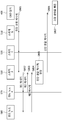
도 7은 본 발명의 일 실시예에 따른 차량 네트워크에서 진단을 위한 통신 노드의 동작 방법을 수행하는 통신 노드를 도시한 블록도이고, 도 8은 본 발명의 일 실시예에 따른 차량 네트워크에서 진단을 위한 통신 노드의 동작 방법을 도시한 순서도이다.FIG. 7 is a block diagram illustrating a communication node performing a method of operation of a communication node for diagnosis in a vehicle network according to an embodiment of the present invention, and FIG. 8 is a flowchart illustrating a method of performing diagnosis in a vehicle network according to an exemplary embodiment of the present invention Fig. 2 is a flowchart showing an operation method of a communication node for the present invention; Fig.
도 7 및 도 8을 참조하면, 차량 네트워크는 OBD 장치(400), 스위치 1(510), 스위치 2(520), 스위치 3(530), 엔드 노드 1(540), 엔드 노드 2(550), 엔드 노드 3(560), 엔드 노드 4(570), 엔드 노드 5(580) 등을 포함할 수 있다. 스위치들(510, 520, 530)은 도 1에 도시된 스위치와 동일 또는 유사한 기능들을 수행할 수 있고, 엔드 노드들(540, 550, 560, 570, 580)은 도 1에 도시된 엔드 노드와 동일 또는 유사한 기능을 수행할 수 있다. 스위치들(510, 520, 530) 및 엔드 노드들(540, 550, 560, 570, 580) 각각은 도 2 내지 4에 도시된 통신 노드와 동일 또는 유사하게 구성될 수 있다.7 and 8, a vehicle network includes an
예를 들어, 스위치 1(510)은 컨트롤러 유닛(511), PHY 계층 유닛 1(512-1), PHY 계층 유닛 2(512-2), PHY 계층 유닛 3(512-3), 전력 회로(513) 등을 포함할 수 있고, 스위치 1(510)에 포함된 컨트롤러 유닛(511), PHY 계층 유닛들(512-1, 512-2, 512-3) 및 전력 회로(513) 각각은 도 2 및 도 3에 도시된 컨트롤러 유닛(220), PHY 계층 유닛(210) 및 전력 회로(240)와 동일 또는 유사할 수 있다. 스위치 2(520)는 컨트롤러 유닛(521), PHY 계층 유닛 1(522-1), PHY 계층 유닛 2(522-2), PHY 계층 유닛 3(522-3), 전력 회로(523) 등을 포함할 수 있고, 스위치 2(520)에 포함된 컨트롤러 유닛(521), PHY 계층 유닛들(522-1, 522-2, 522-3) 및 전력 회로(523) 각각은 도 2 및 도 3에 도시된 컨트롤러 유닛(220), PHY 계층 유닛(210) 및 전력 회로(240)와 동일 또는 유사할 수 있다. 스위치 3(530)은 컨트롤러 유닛(531), PHY 계층 유닛 1(532-1), PHY 계층 유닛 2(532-2), PHY 계층 유닛(532-3) 및 전력 회로(533) 등을 포함할 수 있고, 스위치 3(530)에 포함된 컨트롤러 유닛(531), PHY 계층 유닛들(532-1, 532-2, 532-3) 및 전력 회로(533) 각각은 도 2 및 도 3에 도시된 컨트롤러 유닛(220), PHY 계층 유닛(210) 및 전력 회로(240)와 동일 또는 유사할 수 있다. 엔드 노드들(540, 550, 560, 570, 580) 각각은 컨트롤러 유닛들(541, 551, 561, 571, 581), PHY 계층 유닛들(542, 552, 562, 572, 582) 등을 포함할 수 있고, 엔드 노드들(540, 550, 560, 570, 580)에 포함된 컨트롤러 유닛들(541, 551, 561, 571, 851) 및 PHY 계층 유닛들(542, 552, 562, 572, 582) 각각은 도 2 및 도 3에 도시된 컨트롤러 유닛(220) 및 PHY 계층 유닛(210)과 동일 또는 유사할 수 있다.For example,
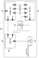
OBD 장치(400)는 스위치들(510, 520, 530)과 버스 라인(bus line)을 통해 연결됨으로써 버스 토폴로지(topology)를 형성할 수 있다. 구체적으로, OBD 장치(400)는 스위치들(510, 520, 530) 각각의 컨트롤러 유닛들(511, 521, 531)과 연결되는 제1 버스 라인을 통해 버스 토폴로지를 형성할 수 있다. 제1 버스 라인은 PWM(pulse width modulation) 방식의 진단을 수행하기 위한 버스 라인일 수 있다. 또한, OBD 장치(400)는 스위치들(510, 520, 530) 각각의 전력 회로들(513, 523, 533)과 연결되는 제2 버스 라인을 통해 버스 토폴로지를 형성할 수 있다. 제2 버스 라인은 PLC(power line communication) 방식의 진단을 수행하기 위한 버스 라인일 수 있다. 즉, 제2 버스 라인은 배터리(600)에서 스위치들(510, 520, 530)에 전력을 공급하는 버스 라인일 수 있다. 다시 말해, OBD 장치(400)는 스위치들(510, 520, 530)에 전력을 공급하는 제2 버스 라인을 통해 버스 토폴로지를 형성할 수 있다.The
스위치 1(510)은 제1 버스 라인에 연결된 컨트롤러 유닛(511) 및 제2 버스 라인에 연결된 전력 회로(513)를 통해 OBD 장치(400)와 연결될 수 있다. 또한, 스위치 1(510)은 PHY 계층 유닛 1(512-1)을 통해 엔드 노드 1(540)(예를 들어, 엔드 노드 1(540)의 PHY 계층 유닛(542))과 연결될 수 있고, PHY 계층 유닛 2(512-2)를 통해 엔드 노드 2(550)(예를 들어, 엔드 노드 2(550)의 PHY 계층 유닛(552))와 연결될 수 있고, PHY 계층 유닛 3(512-3)을 통해 스위치 2(520)(예를 들어, 스위치 2(520)의 PHY 계층 유닛 1(522-1))과 연결될 수 있다. 스위치 1(510)과 스위치 2(520) 간의 통신은 MII, RMII, GMII, RGMII, SGMII 및 XGMII 중에서 하나의 인터페이스를 사용하여 수행될 수 있다.The
스위치 2(520)는 제1 버스 라인에 연결된 컨트롤러 유닛(521) 및 제2 버스 라인에 연결된 전력 회로(523)를 통해 OBD 장치(400)와 연결될 수 있다. 또한, 스위치 2(520)는 PHY 계층 유닛 1(522-1)을 통해 스위치 1(510)(예를 들어, 스위치 1(510)의 PHY 계층 유닛 3(512-3))과 연결될 수 있고, PHY 계층 유닛 2(522-2)를 통해 엔드 노드 3(560)(예를 들어, 엔드 노드 3(560)의 PHY 계층 유닛(562))과 연결될 수 있고, PHY 계층 유닛 3(522-3)을 통해 스위치 3(530)(예를 들어, 스위치 3(530)의 PHY 계층 유닛 1(532-1))과 연결될 수 있다. 스위치 2(520)와 스위치 3(530) 간의 통신은 MII, RMII, GMII, RGMII, SGMII 및 XGMII 중에서 하나의 인터페이스를 사용하여 수행될 수 있다.The
스위치 3(530)은 제1 버스 라인에 연결된 컨트롤러 유닛(531) 및 제2 버스 라인에 연결된 전력 회로(532)를 통해 OBD 장치(400)와 연결될 수 있다. 또한, 스위치 3(530)은 PHY 계층 유닛 1(532-1)을 통해 스위치 2(520)(예를 들어, 스위치 2(520)의 PHY 계층 유닛 3(522-3))와 연결될 수 있고, PHY 계층 유닛 2(532-2)를 통해 엔드 노드 4(570)(예를 들어, 엔드 노드 4(570)의 PHY 계층 유닛(572))와 연결될 수 있고, PHY 계층 유닛 3(532-3)을 통해 엔드 노드 5(580)(예를 들어, 엔드 노드 5(580)의 PHY 계층 유닛(582))와 연결될 수 있다.The
한편, OBD 장치(400)는 진단 요청 메시지를 생성할 수 있고, 생성된 진단 요청 메시지를 차량 네트워크의 이더넷 경로를 통해 스위치 1(510)(예를 들어, 스위치 1(510)의 컨트롤러 유닛(511))로 전송할 수 있다. 이후, OBD 장치(400)는 진단 요청 메시지 전송 종료 시점부터 미리 정의된 시간 내에 진단 요청 메시지에 대한 응답인 진단 응답 메시지(또는, ACK 메시지)를 수신하지 못한 경우, 후술되는 동작 방법을 수행할 수 있다. OBD 장치(400)는 진단 요청 메시지를 제1 버스 라인 및 제2 버스 라인 중 적어도 하나를 통해 스위치들(510, 520, 530)로 전송할 수 있다(S601). 여기서, OBD 장치(400)에서 제1 버스 라인을 통해 전송되는 진단 요청 메시지는 PWM 방식에 기초하여 진단을 수행하기 위한 미리 설정된 주파수로 전송될 수 있고, PWM 방식에 기초한 진단 동작을 지시하는 듀티비(duty ratio)를 포함할 수 있다.On the other hand, the
이후, 스위치들(510, 520, 530)은 OBD 장치(400)에서 전송되는 진단 요청 메시지를 수신할 수 있다. 구체적으로, OBD 장치(400)에서 진단 요청 메시지가 제1 버스 라인을 통해 전송되는 경우, 스위치들(510, 520, 530)은 제1 버스 라인과 연결된 컨트롤러 유닛들(511, 521, 531)을 통해 진단 요청 메시지를 수신할 수 있다. 또한, 제1 버스 라인으로 연결된 수신되는 진단 요청 메시지는 단계 S601에서 설명한 바와 같이, PWM 방식에 기초하여 진단을 수행하기 위한 미리 설정된 주파수로 전송될 수 있고, PWM 방식에 기초한 진단 동작을 지시하는 듀티비(duty ratio)를 포함할 수 있다. 반면, OBD 장치(400)에서 진단 요청 메시지가 제2 버스 라인을 통해 전송되는 경우, 스위치들(510, 520, 530)은 제2 버스 라인과 연결된 전력 회로들(513, 523, 533)을 통해 진단 요청 메시지를 수신할 수 있다. 이때, OBD 장치(400)에서 진단 요청 메시지가 제2 버스 라인과 연결된 전력 회로들(513, 523, 533)을 통해 수신되는 경우, 수신된 진단 요청 메시지는 스위치들(510, 520, 530) 각각의 전력 회로들(513, 523, 533)에서 컨트롤러 유닛들(511, 521, 531)로 전송될 수 있다.Then, the
이후, 스위치들(510, 520, 530)은 진단 요청 메시지에 포함된 식별자(identifier)를 확인할 수 있다. 여기서, 진단 요청 메시지에 포함된 식별자는 스위치 3(530)의 식별자인 것으로 가정할 수 있다. 예를 들어, 식별자는 DIP(duel in-line package) 스위치를 이용하여 설정되는 스위치 번호(switch number)를 의미할 수 있다. 즉, 스위치들(510, 520, 530)은 DIP 스위치를 이용하여 스위치 번호가 미리 설정될 수 있고, 미리 설정된 스위치 번호를 식별자로 사용할 수 있다. OBD 장치(400)는 진단 요청 메시지를 생성하는 과정에서 진단을 수행하기 위한 스위치를 선택할 수 있고, 선택된 스위치의 식별자를 포함하는 진단 요청 메시지를 생성할 수 있다.Then, the
즉, 스위치 1(510)은 진단 요청 메시지에 포함된 스위치 3(530)의 식별자를 확인할 수 있고, 수신된 진단 요청 메시지가 스위치 3(530)의 진단을 위한 메시지임을 확인할 수 있다. 또한, 스위치 2(520)는 진단 요청 메시지에 포함된 스위치 3(530)의 식별자를 확인할 수 있고, 수신된 진단 요청 메시지가 스위치 3(530)의 진단을 위한 메시지임을 확인할 수 있다. 한편, 스위치 3(530)은 진단 요청 메시지에 포함된 스위치 3(530)의 식별자를 확인할 수 있고, 수신된 진단 요청 메시지가 자신에게 전송된 진단 요청 메시지임을 판단할 수 있다.That is, the
이후, 스위치 3(530)은 진단 요청 메시지에 포함된 진단 동작을 지시하는 지시자를 확인할 수 있고, 확인된 지시자가 지시하는 진단 동작을 수행할 수 있다. 여기서, 진단 요청 메시지는 스위치 3(530)의 리셋(reset), 스위치 3(530)치에 포함된 PHY 계층 유닛들(532-1, 532-2, 532-3)의 리셋, 스위치 3(530)에 포함된 PHY 계층 유닛들(532-1, 532-2, 532-3)의 수신 확인 및 스위치 3(530)에 포함된 PHY 계층 유닛들(532-1, 532-2, 532-3)의 발신 확인 중 적어도 하나의 동작을 지시하는 지시자 등과 같은 진단 동작을 지시하는 지시자를 의미할 수 있다. 여기서, 진단 요청 메시지에 포함된 진단 동작을 지시하는 지시자가 스위치 3(530)에 포함된 PHY 계층 유닛들(532-1, 532-2, 532-3) 중 PHY 계층 유닛 1(532-1)을 제외한 나머지 PHY 계층 유닛들(532-2, 532-3)의 수신 확인을 지시하는 지시자인 것으로 가정할 수 있다.Thereafter, the switch 3 (530) can confirm the indicator indicating the diagnostic operation included in the diagnostic request message, and can perform the diagnostic operation indicated by the confirmed indicator. Here, the diagnostic request message includes a reset of the
이후, 스위치 3(530)은 PHY 계층 유닛들(532-2, 532-3)의 상태를 판단하기 위한 제1 메시지를 생성할 수 있다. 예를 들어, 스위치 3(530)은 컨트롤러 유닛(531)을 통해 계층 유닛들(532-2, 532-3)의 상태를 판단하기 위한 제1 메시지를 생성할 수 있다. 이후, 스위치 3(530)의 컨트롤러 유닛(531)에서 생성된 제1 메시지는 PHY 계층 유닛들(532-3, 532-3)에 전송될 수 있다. 이후, 스위치 3(530)은 생성된 제1 메시지를 엔드 노드 4(570) 및 엔드 노드(570)로 전송할 수 있다(S802). 구체적으로, 스위치 3(530)은 엔드 노드 4(570)의 PHY 계층 유닛(572)와 연결된 PHY 계층 유닛 2(532-2)를 통해 제1 메시지를 엔드 노드 4(570)로 전송할 수 있고, 엔드 노드 5(580)의 PHY 계층 유닛(582)와 연결된 PHY 계층 유닛 3(532-3)을 통해 제1 메시지를 엔드 노드 5(580)로 전송할 수 있다.Then, the
이후, 엔드 노드 4(570)는 PHY 계층 유닛(572)을 통해 스위치 3(530)으로부터 제1 메시지를 수신할 수 있다. 이후, 엔드 노드 4(570)는 제1 메시지에 대한 응답인 제2 메시지(또는, ACK(acknowledgement) 메시지)를 생성할 수 있다. 이후, 엔드 노드 4(570)는 생성된 제2 메시지를 PHY 계층 유닛(572)를 통해 스위치 3(530)으로 전송할 수 있다(S803). 한편, 엔드 노드 5(580)는 PHY 계층 유닛(582)을 통해 스위치 3(530)으로부터 제1 메시지를 수신할 수 있다. 이후, 엔드 노드 5(580)는 제1 메시지에 대한 응답인 제2 메시지(또는, ACK 메시지)를 생성할 수 있다. 이후, 엔드 노드 5(580)는 생성된 제2 메시지(또는 ACK 메시지)를 PHY 계층 유닛(582)을 통해 스위치 3(530)으로 전송할 수 있다(S804).The end node 4 570 may then receive the first message from the
한편, 스위치 3(530)은 엔드 노드 4(570) 및 엔드 노드 5(580)로부터 제1 메시지에 대한 응답인 제2 메시지(또는, ACK 메시지)를 수신할 수 있다. 구체적으로, 스위치 3(530)은 PHY 계층 유닛 2(532-2)를 통해 엔드 노드 4(570)로부터 제2 메시지(또는, ACK 메시지)를 수신할 수 있고, PHY 계층 유닛 3(532-3)을 통해 엔드 노드 5)580)로부터 제2 메시지(또는, ACK 메시지)를 수신할 수 있다. 이때, 스위치 3(530)은 엔드 노드 4(570) 및 엔드 노드 5(580)로부터 제2 메시지(또는, ACK 메시지)를 수신하는 경우, 엔드 노드 4(570)와 연결된 PHY 계층 유닛 2(532-2) 및 엔드 노드 5(580)와 연결된 PHY 계층 유닛 3(532-3) 각각의 상태를 정상 상태인 것으로 판단할 수 있다. 반면, 스위치 3(530)은 제1 메시지의 전송 종료 시점부터 미리 정의된 시간 내에 제1 메시지에 대한 응답인 제2 메시지(또는, ACK 메시지)를 수신하지 못한 경우, 제2 메시지(또는, ACK 메시지)를 전송하지 않은 엔드 노드와 연결된 스위치 3(530)의 PHY 계층 유닛의 상태를 고장 상태인 것으로 판단할 수 있다. 또한, 스위치 3(530)은 제2 메시지(또는, ACK)메시지를 전송하지 않은 엔드 노드의 상태를 고장 상태인 것으로 판단할 수도 있다.Meanwhile, the
이후, 스위치 3(530)은 진단 응답 메시지를 생성할 수 있다(S805). 여기서, 진단 응답 메시지는 PHY 계층 유닛들(532-2, 532-3)의 상태를 나타내는 지시자(예를 들어, 고장 상태 또는 정상 상태를 나타내는 지시자) 및 고상 상태인 것으로 판단된 엔드 노드의 식별자 등을 포함할 수 있다. 이후, 스위치 3(530)은 진단 응답 메시지를 OBD 장치(400)로 전송할 수 있다(S806). 구체적으로, 스위치 3(530)은 생성된 진단 응답 메시지를 진단 요청 메시지를 수신한 버스 라인을 통해 OBD 장치(400)로 전송할 수 있다. 예를 들어, 스위치 3(530)은 진단 요청 메시지를 제1 버스 라인을 통해 수신한 경우, 진단 응답 메시지를 제1 버스 라인을 통해 전송할 수 있다. 또한, 스위치 3(530)은 진단 요청 메시지를 제2 버스 라인을 통해 수신한 경우, 진단 응답 메시지를 제2 버스 라인을 통해 전송할 수 있다.Thereafter, the
이후, OBD 장치(400)는 스위치 3(530)으로부터 진단 요청 메시지에 대한 응답인 진단 응답 메시지를 수신할 수 있다. 이후, OBD 장치(400)는 진단 응답 메시지에 포함된 스위치 3(530)의 PHY 계층 유닛들(532-2, 532-3)에 대한 상태를 나타내는 지시자 및 고상 상태인 것으로 판단된 엔드 노드의 식별자 등을 확인함으로써, 고장 상태를 확인할 수 있다(S807).Thereafter, the
상술한 바와 같은 방법을 통해, OBD 장치(400)는 스위치들(510, 520, 530) 또는 스위치 (510, 520, 530)에 연결된 엔드 노드(540, 550, 560, 570, 580)에 대한 고장 상태를 확인할 수 있다. 즉, OBD 장치(400)는 제1 버스 라인 및 제2 버스 라인을 통해 스위치들(510, 520, 530)과 버스 토폴로지를 형성함으로써, 스위치들(510, 520, 530)에 대하여 선택적으로 스위치를 진단할 수 있다. 예를 들어, OBD 장치(400)가 스위치 1(510)과 연결되고, 스위치 1(510)이 스위치 2(520)와 연결되고, 스위치 2(520)가 스위치 3(530)과 연결되는 구조와 같은 계층적인 구조는 스위치 3(530)의 고장 상태를 확인하는 과정에서 스위치 1(510) 또는 스위치 2(520)가 고장 상태인 경우, 진단 응답 메시지를 수신하지 못하는 상황이 발생할 수 있다. 이와 같은 경우, OBD 장치(400)는 스위치 1(510), 스위치 2(520), 스위치(530) 중 고장 상태인 스위치를 판단하는데 어려움이 있을 수 있다. 그러나, 도 7 내지 도 8을 참조하여 설명된 본 발명의 일 실시예에 따른 차량 네트워크에서 진단을 위한 통신 노드의 동작 방법은 OBD 장치(400)와 제1 버스 라인 및 제2 버스 라인 중 적어도 하나를 통해 연결된 스위치에서 자체적으로 진단을 수행할 수 있다.The
본 발명에 따른 방법들은 다양한 컴퓨터 수단을 통해 수행될 수 있는 프로그램 명령 형태로 구현되어 컴퓨터 판독 가능 매체에 기록될 수 있다. 컴퓨터 판독 가능 매체는 프로그램 명령, 데이터 파일, 데이터 구조 등을 단독으로 또는 조합하여 포함할 수 있다. 컴퓨터 판독 가능 매체에 기록되는 프로그램 명령은 본 발명을 위해 특별히 설계되고 구성된 것들이거나 컴퓨터 소프트웨어 당업자에게 공지되어 사용 가능한 것일 수도 있다.The methods according to the present invention can be implemented in the form of program instructions that can be executed through various computer means and recorded on a computer readable medium. The computer readable medium may include program instructions, data files, data structures, and the like, alone or in combination. The program instructions recorded on the computer readable medium may be those specially designed and constructed for the present invention or may be available to those skilled in the computer software.
컴퓨터 판독 가능 매체의 예에는 롬(rom), 램(ram), 플래시 메모리(flash memory) 등과 같이 프로그램 명령을 저장하고 수행하도록 특별히 구성된 하드웨어 장치가 포함된다. 프로그램 명령의 예에는 컴파일러(compiler)에 의해 만들어지는 것과 같은 기계어 코드뿐만 아니라 인터프리터(interpreter) 등을 사용해서 컴퓨터에 의해 실행될 수 있는 고급 언어 코드를 포함한다. 상술한 하드웨어 장치는 본 발명의 동작을 수행하기 위해 적어도 하나의 소프트웨어 모듈로 작동하도록 구성될 수 있으며, 그 역도 마찬가지이다.Examples of computer readable media include hardware devices that are specially configured to store and execute program instructions, such as ROM, RAM, flash memory, and the like. Examples of program instructions include machine language code such as those generated by a compiler, as well as high-level language code that can be executed by a computer using an interpreter or the like. The hardware devices described above may be configured to operate with at least one software module to perform the operations of the present invention, and vice versa.
이상 실시예를 참조하여 설명하였지만, 해당 기술 분야의 숙련된 당업자는 하기의 특허 청구의 범위에 기재된 본 발명의 사상 및 영역으로부터 벗어나지 않는 범위 내에서 본 발명을 다양하게 수정 및 변경시킬 수 있음을 이해할 수 있을 것이다.It will be understood by those skilled in the art that various changes in form and details may be made therein without departing from the spirit and scope of the invention as defined in the appended claims. It will be possible.
Claims (20)
상기 복수의 스위치들은 버스 라인(bus line)에 의해 연결됨으로써 버스 토폴로지(topology)를 형성하고,
상기 버스 라인을 통해 OBD(on-board diagnostic) 장치로부터 진단 요청 메시지(diagnosis request message)를 수신하는 단계;
상기 진단 요청 메시지에 의해 지시되는 진단 동작을 수행하는 단계; 및
상기 진단 동작의 수행 결과를 상기 버스 라인을 통해 상기 OBD 장치에 전송하는 단계를 포함하는 제1 스위치의 동작 방법.CLAIMS What is claimed is: 1. A method of operating a first switch among a plurality of switches in a vehicle network comprising a plurality of switches,
The plurality of switches are connected by a bus line to form a bus topology,
Receiving a diagnosis request message from an on-board diagnostic (OBD) device through the bus line;
Performing a diagnostic operation indicated by the diagnostic request message; And
And transmitting a result of performing the diagnostic operation to the OBD device via the bus line.
상기 복수의 스위치들은,
PWM(pulse width modulation) 방식의 진단을 수행하기 위한 제1 버스 라인 또는 PLC(power line communication) 방식의 진단을 수행하기 위한 제2 버스 라인에 의해 연결되는 것을 특징으로 하는 제1 스위치의 동작 방법.The method according to claim 1,
The plurality of switches may include:
Wherein the first bus line is connected to a first bus line for performing diagnosis of a pulse width modulation (PWM) method or a second bus line for performing diagnosis of a PLC (power line communication) method.
상기 제1 버스 라인은,
상기 복수의 스위치들 각각의 컨트롤러 유닛(controller unit) 간을 연결하는 것을 특징으로 하는 제1 스위치의 동작 방법.The method of claim 2,
Wherein the first bus line includes:
And connecting controller units of each of the plurality of switches.
상기 진단 동작을 수행하는 단계는,
상기 제1 버스 라인으로 연결된 상기 제1 스위치의 컨트롤러 유닛에서 상기 진단 요청 메시지를 수신하는 경우, 상기 컨트롤러 유닛이 상기 진단 동작을 지시하는 지시자가 포함된 제1 메시지를 생성하는 단계;
상기 컨트롤러 유닛이 상기 생성된 제1 메시지를 상기 제1 스위치의 PHY 계층 유닛에 전송하는 단계; 및
상기 제1 스위치의 PHY 계층 유닛이 상기 지시자가 지시하는 진단 동작을 수행하는 단계를 더 포함하는 것을 특징으로 하는 제1 스위치의 동작 방법.The method of claim 3,
Wherein the performing the diagnostic operation comprises:
Generating a first message including an indicator indicating the diagnostic operation when the controller unit receives the diagnosis request message from the controller unit of the first switch connected to the first bus line;
The controller unit transmitting the generated first message to a PHY layer unit of the first switch; And
Further comprising the step of the PHY layer unit of the first switch performing a diagnostic operation indicated by the indicator.
상기 제1 버스 라인으로 연결된 상기 제1 스위치의 컨트롤러 유닛을 통해 수신되는 상기 진단 요청 메시지는 PWM 방식에 기초하여 진단을 수행하기 위한 미리 설정된 주파수로 전송되고, 상기 PWM 방식에 기초한 진단 동작을 지시하는 듀티비(duty ratio)를 포함하는 것을 특징으로 하는 제1 스위치의 동작 방법.The method of claim 4,
Wherein the diagnostic request message received via the controller unit of the first switch connected to the first bus line is transmitted at a predetermined frequency for performing diagnosis based on the PWM method and instructs the diagnostic operation based on the PWM method Wherein the first switch comprises a duty ratio.
상기 제2 버스 라인은,
상기 복수의 스위치들 각각의 포함된 전력 회로(power circuit) 간을 연결하는 것을 특징으로 하는 제1 스위치의 동작 방법.The method of claim 2,
Wherein the second bus line comprises:
And connecting the power circuits included in each of the plurality of switches.
상기 진단 동작을 수행하는 단계는,
상기 제2 버스 라인으로 연결된 상기 제1 스위치의 전력 회로를 통해 상기 진단 요청 메시지가 수신되는 경우, 상기 전력 회로가 상기 진단 요청 메시지를 상기 제1 스위치의 컨트롤러 유닛에 전송하는 단계;
상기 컨트롤러 유닛이 상기 진단 동작을 지시하는 지시자가 포함된 제1 메시지를 생성하는 단계;
상기 컨트롤러 유닛이 상기 생성된 제1 메시지를 상기 제1 스위치의 PHY 계층 유닛에 전송하는 단계; 및
상기 제1 스위치의 PHY 계층 유닛이 상기 지시자가 지시하는 진단 동작을 수행하는 단계를 더 포함하는 것을 특징으로 하는 제1 스위치의 동작 방법.The method of claim 6,
Wherein the performing the diagnostic operation comprises:
Sending the diagnostic request message to the controller unit of the first switch when the diagnostic request message is received via the power circuit of the first switch connected to the second bus line;
Generating a first message including an indicator that the controller unit directs the diagnostic operation;
The controller unit transmitting the generated first message to a PHY layer unit of the first switch; And
Further comprising the step of the PHY layer unit of the first switch performing a diagnostic operation indicated by the indicator.
상기 복수의 스위치들 각각의 식별자는 DIP(duel in-line package) 스위치에 기초하여 설정되고, 상기 진단 요청 메시지는 상기 설정된 제1 스위치의 식별자(identifier)를 포함하는 것을 특징으로 하는 제1 스위치의 동작 방법.The method according to claim 1,
Wherein the identifier of each of the plurality of switches is set based on a duel in-line package (DIP) switch, and the diagnostic request message includes an identifier of the set first switch. How it works.
상기 진단 요청 메시지는,
상기 복수의 스위치들의 리셋(reset), 상기 제1 스위치에 포함된 PHY 계층 유닛의 리셋, 상기 제1 스위치에 포함된 PHY 계층 유닛의 수신 확인 및 상기 제1 스위치에 포함된 PHY 계층 유닛의 발신 확인 중 적어도 하나의 동작을 지시하는 지시자를 포함하는 것을 특징으로 하는 제1 스위치의 동작 방법.The method according to claim 1,
The diagnostic request message includes:
A reset of the plurality of switches, a reset of the PHY layer unit included in the first switch, an acknowledgment of the PHY layer unit included in the first switch, and an acknowledgment of the PHY layer unit included in the first switch And an indicator indicating an operation of at least one of the first switch and the second switch.
상기 복수의 스위치들은 버스 라인(bus line)에 의해 연결됨으로써 버스 토폴로지(topology)를 형성하고,
상기 복수의 스위치들 중 적어도 하나의 스위치를 진단하기 위한 진단 요청 메시지(diagnosis request message)를 생성하는 단계;
상기 버스 라인을 통해 상기 생성된 진단 요청 메시지를 상기 적어도 하나의 스위치로 전송하는 단계;
상기 적어도 하나의 스위치로부터 상기 적어도 하나의 스위치의 진단 결과에 대한 정보가 포함된 진단 응답 메시지(diagnosis response message)를 수신하는 단계; 및
상기 진단 응답 메시지에 기초하여 상기 적어도 하나의 스위치에 대한 진단을 수행하는 단계를 포함하는 OBD 장치의 동작 방법.1. An operating method performed on an on-board diagnostic (OBD) device for diagnosing a plurality of switches included in a vehicle network,
The plurality of switches are connected by a bus line to form a bus topology,
Generating a diagnosis request message for diagnosing at least one switch of the plurality of switches;
Transmitting the generated diagnostic request message to the at least one switch via the bus line;
Receiving a diagnosis response message including information on a diagnosis result of the at least one switch from the at least one switch; And
And performing diagnostics on the at least one switch based on the diagnostic response message.
상기 OBD 장치의 동작 방법은,
상기 차량 네트워크의 이더넷(ethernet) 경로를 통해 진단 응답 메시지를 수신하지 못한 경우, 수행되는 것을 특징으로 하는 OBD 장치의 동작 방법.The method of claim 10,
The operation method of the OBD apparatus includes:
And when the diagnostic response message is not received through the ethernet path of the vehicle network.
상기 진단 요청 메시지는,
상기 적어도 하나의 스위치에 포함된 PHY 계층 유닛의 리셋(reset), 상기 적어도 하나의 스위치에 포함된 PHY 계층 유닛의 수신 확인 및 상기 적어도 하나의 스위치에 포함된 PHY 계층 유닛의 발신 확인 중 적어도 하나의 동작을 지시하는 지시자를 포함하는 것을 특징으로 하는 OBD 장치의 동작 방법.The method of claim 10,
The diagnostic request message includes:
At least one of a reset of a PHY layer unit included in the at least one switch, an acknowledgment of a PHY layer unit included in the at least one switch, and an acknowledgment of a PHY layer unit included in the at least one switch And an indicator for instructing operation of the OBD device.
상기 복수의 스위치들 각각의 식별자는 DIP(duel in-line package) 스위치에 기초하여 설정되고, 상기 진단 요청 메시지는 상기 설정된 적어도 하나의 스위치의 식별자(identifier)를 포함하는 것을 특징으로 하는 OBD 장치의 동작 방법.The method of claim 10,
Wherein the identifier of each of the plurality of switches is set based on a duel in-line package (DIP) switch, and the diagnostic request message includes an identifier of the set at least one switch. How it works.
상기 복수의 스위치들은,
PWM(pulse width modulation) 방식의 진단을 수행하기 위한 제1 버스 라인 및 PLC(power line communication) 방식의 진단을 수행하기 위한 제2 버스 라인에 의해 연결되는 것을 특징으로 하는 OBD 장치의 동작 방법.The method of claim 10,
The plurality of switches may include:
A first bus line for performing a PWM (pulse width modulation) diagnosis and a second bus line for performing diagnosis of a power line communication (PLC) method.
상기 제1 버스 라인은,
상기 복수의 스위치들 각각의 컨트롤러 유닛(controller unit) 간을 연결하는 것을 특징으로 하는 OBD 장치의 동작 방법.15. The method of claim 14,
Wherein the first bus line includes:
And connecting controller units of each of the plurality of switches.
상기 제2 버스 라인은,
상기 복수의 스위치들 각각의 포함된 전력 회로(power circuit) 간을 연결하는 것을 특징으로 하는 OBD 장치의 동작 방법.15. The method of claim 14,
Wherein the second bus line comprises:
And connecting power circuits included in each of the plurality of switches.
컨트롤러 유닛(controller unit);
적어도 하나의 PHY 계층 유닛; 및
상기 제1 스위치에 전력을 공급하는 전력 회로(power circuit)를 포함하며,
상기 컨트롤러 유닛은 상기 버스 라인과 연결된 OBD(on-board) 장치로부터 진단 요청 메시지(diagnosis request message)를 수신하고,
상기 컨트롤러 유닛은 상기 진단 요청 메시지에 의해 지시되는 진단 동작을 확인하고,
상기 컨트롤러 유닛은 상기 진단 동작의 수행을 요청하는 지시자를 상기 적어도 하나의 PHY 계층 유닛에 전송하고,
상기 지시자를 수신한 상기 적어도 하나의 PHY 계층 유닛은 상기 지시자에 의해 요청되는 상기 진단 동작을 수행하는 제1 스위치.A first one of a plurality of switches connected by a bus line in a vehicle network to form a bus topology,
A controller unit;
At least one PHY layer unit; And
And a power circuit for supplying power to the first switch,
The controller unit receives a diagnosis request message from an OBD (on-board) device connected to the bus line,
The controller unit confirms the diagnostic operation indicated by the diagnosis request message,
The controller unit transmits to the at least one PHY layer unit an indicator requesting to perform the diagnostic operation,
And the at least one PHY layer unit receiving the indicator performs the diagnostic operation requested by the indicator.
상기 복수의 스위치들은,
PWM(pulse width modulation) 방식의 진단을 수행하기 위한 제1 버스 라인 또는 PLC(power line communication) 방식의 진단을 수행하기 위한 제2 버스 라인에 의해 연결되는 것을 특징으로 하는 제1 스위치.18. The method of claim 17,
The plurality of switches may include:
Wherein the first switch is connected by a first bus line for performing diagnosis of a pulse width modulation (PWM) method or by a second bus line for performing diagnosis of a PLC (power line communication) method.
상기 제1 버스 라인은 상기 제1 스위치의 컨트롤러 유닛과 연결되고, 상기 제2 버스 라인은 상기 제1 스위치의 전력 회로와 연결되는 것을 특징으로 하는 제1 스위치.19. The method of claim 18,
Wherein the first bus line is connected to the controller unit of the first switch and the second bus line is connected to the power circuit of the first switch.
상기 진단 요청 메시지는,
상기 적어도 하나의 PHY 계층 유닛의 리셋(reset), 상기 적어도 하나의 PHY 계층 유닛의 수신 확인 및 상기 적어도 하나의 PHY 계층 유닛의 발신 확인 중 적어도 하나의 동작을 지시하는 것을 특징으로 제1 스위치.18. The method of claim 17,
The diagnostic request message includes:
A reset of the at least one PHY layer unit, an acknowledgment of the at least one PHY layer unit, and an origination confirmation of the at least one PHY layer unit.
Priority Applications (3)
| Application Number | Priority Date | Filing Date | Title |
|---|---|---|---|
| KR1020170075607A KR102355092B1 (en) | 2017-06-15 | 2017-06-15 | Operation method of communication node for diagnosing in vehicle network |
| US15/831,138 US10594587B2 (en) | 2017-06-15 | 2017-12-04 | Operation method of communication node for diagnosing vehicle network |
| DE102018106414.4A DE102018106414A1 (en) | 2017-06-15 | 2018-03-20 | Operating method of a communication node for diagnosing a vehicle network |
Applications Claiming Priority (1)
| Application Number | Priority Date | Filing Date | Title |
|---|---|---|---|
| KR1020170075607A KR102355092B1 (en) | 2017-06-15 | 2017-06-15 | Operation method of communication node for diagnosing in vehicle network |
Publications (2)
| Publication Number | Publication Date |
|---|---|
| KR20180136645A true KR20180136645A (en) | 2018-12-26 |
| KR102355092B1 KR102355092B1 (en) | 2022-01-24 |
Family
ID=64457618
Family Applications (1)
| Application Number | Title | Priority Date | Filing Date |
|---|---|---|---|
| KR1020170075607A KR102355092B1 (en) | 2017-06-15 | 2017-06-15 | Operation method of communication node for diagnosing in vehicle network |
Country Status (3)
| Country | Link |
|---|---|
| US (1) | US10594587B2 (en) |
| KR (1) | KR102355092B1 (en) |
| DE (1) | DE102018106414A1 (en) |
Cited By (1)
| Publication number | Priority date | Publication date | Assignee | Title |
|---|---|---|---|---|
| WO2020209441A1 (en) * | 2019-04-08 | 2020-10-15 | 주식회사 디젠 | Device and method for preventing network hacking of vehicle by using gateway |
Families Citing this family (6)
| Publication number | Priority date | Publication date | Assignee | Title |
|---|---|---|---|---|
| KR20210120287A (en) * | 2020-03-26 | 2021-10-07 | 현대자동차주식회사 | Diagnostic system, and vehicle |
| US11777835B1 (en) * | 2020-07-20 | 2023-10-03 | Ethernovia Inc. | Functional safety in a vehicle networking system |
| EP4211877A1 (en) * | 2020-09-11 | 2023-07-19 | Lenovo (Singapore) Pte. Ltd. | Determining a network system issue |
| CN112556105B (en) * | 2020-12-09 | 2022-05-31 | 广东美的暖通设备有限公司 | Control method, control device, communication system and storage medium for communication equipment |
| US11768728B2 (en) * | 2021-12-16 | 2023-09-26 | Nio Technology (Anhui) Co., Ltd. | Routing multiple diagnostic pathways |
| KR20240026754A (en) | 2022-08-22 | 2024-02-29 | 현대자동차주식회사 | Method and system for diagnosing communication channel status in vehicle network |
Citations (2)
| Publication number | Priority date | Publication date | Assignee | Title |
|---|---|---|---|---|
| US20120173905A1 (en) * | 2010-11-03 | 2012-07-05 | Broadcom Corporation | Providing power over ethernet within a vehicular communication network |
| US20140036693A1 (en) * | 2012-07-27 | 2014-02-06 | Toyota Jidosha Kabushiki Kaisha | Communication system and communication method |
Family Cites Families (10)
| Publication number | Priority date | Publication date | Assignee | Title |
|---|---|---|---|---|
| US7596459B2 (en) * | 2001-02-28 | 2009-09-29 | Quadlogic Controls Corporation | Apparatus and methods for multi-channel electric metering |
| US9432347B2 (en) * | 2010-09-20 | 2016-08-30 | Bosch Automotive Service Solutions Inc. | Secure desktop interface |
| US20130201316A1 (en) * | 2012-01-09 | 2013-08-08 | May Patents Ltd. | System and method for server based control |
| US10545515B2 (en) * | 2015-04-27 | 2020-01-28 | Hewlett Packard Enterprise Development Lp | Virtualized fan speed measurement |
| US11524656B2 (en) * | 2015-05-19 | 2022-12-13 | Voyomotive, Llc | Independent vehicle security method and apparatus |
| US10611255B2 (en) * | 2015-07-10 | 2020-04-07 | Lg Innotek Co., Ltd. | Device and method for charging electric vehicle with different charging standards |
| US9964415B2 (en) * | 2015-11-13 | 2018-05-08 | Nio Usa, Inc. | Tracking power consumption and payment |
| US10252631B2 (en) * | 2015-11-13 | 2019-04-09 | Nio Usa, Inc. | Communications between vehicle and charging system |
| WO2017180816A1 (en) * | 2016-04-15 | 2017-10-19 | Voyomotive, Llc | Power line communication smart relay |
| US10581543B2 (en) * | 2017-01-10 | 2020-03-03 | Infineon Technologies Ag | Synchronization mechanism for high speed sensor interface |
-
2017
- 2017-06-15 KR KR1020170075607A patent/KR102355092B1/en active IP Right Grant
- 2017-12-04 US US15/831,138 patent/US10594587B2/en active Active
-
2018
- 2018-03-20 DE DE102018106414.4A patent/DE102018106414A1/en active Pending
Patent Citations (2)
| Publication number | Priority date | Publication date | Assignee | Title |
|---|---|---|---|---|
| US20120173905A1 (en) * | 2010-11-03 | 2012-07-05 | Broadcom Corporation | Providing power over ethernet within a vehicular communication network |
| US20140036693A1 (en) * | 2012-07-27 | 2014-02-06 | Toyota Jidosha Kabushiki Kaisha | Communication system and communication method |
Cited By (1)
| Publication number | Priority date | Publication date | Assignee | Title |
|---|---|---|---|---|
| WO2020209441A1 (en) * | 2019-04-08 | 2020-10-15 | 주식회사 디젠 | Device and method for preventing network hacking of vehicle by using gateway |
Also Published As
| Publication number | Publication date |
|---|---|
| US10594587B2 (en) | 2020-03-17 |
| KR102355092B1 (en) | 2022-01-24 |
| DE102018106414A1 (en) | 2018-12-20 |
| US20180367436A1 (en) | 2018-12-20 |
Similar Documents
| Publication | Publication Date | Title |
|---|---|---|
| KR102355092B1 (en) | Operation method of communication node for diagnosing in vehicle network | |
| KR102589373B1 (en) | Method and apparatus for wakeup of communication node in automotive network | |
| KR102286050B1 (en) | Method for preventing diagnostic errors in vehicle network and apparatus for the same | |
| KR102390465B1 (en) | Method for power management in network and apparatus for the same | |
| KR102337548B1 (en) | Method for diagnosing network and apparatus for the same | |
| US20070061056A1 (en) | Bypass switch for an ethernet-type network | |
| KR102422404B1 (en) | Method for supplying power in network and apparatus therefor | |
| KR102294634B1 (en) | Operation method of communication node in network | |
| US10673986B2 (en) | Operation method of communication node for selective wake-up in vehicle network | |
| KR20170087602A (en) | Method for converting operation mode in network | |
| KR20190013165A (en) | Device of ethernet communication in vehicle, and method for error recover of end node and switch | |
| KR20160146055A (en) | Operating method of a communication node in automotive network | |
| KR102293037B1 (en) | Operation method of communication node in network | |
| KR20180029854A (en) | Diagnostic methods and devices in vehicle network | |
| Kostrzewa et al. | Fast failover in ethernet-based automotive networks | |
| KR102446092B1 (en) | Method for diagnosing link status in network | |
| JP2010500838A (en) | Device for connecting an external device to a serial FlexRay data bus | |
| KR102390481B1 (en) | Operation method of communication node in network | |
| KR102355085B1 (en) | Operation method of communication node for selective wakeup in vehicle network | |
| US20190305983A1 (en) | Method and apparatus for configuring backup path in vehicle network | |
| KR102352504B1 (en) | System for verification of non-registered device based on imformation of ethernet switch and method for the same | |
| EP1638260A1 (en) | Bypass switch for an ethernet-type network | |
| KR102610921B1 (en) | Method and apparatus for setting backup path in automotive network | |
| JP2017114406A (en) | Network system | |
| KR20160146048A (en) | Operating method of a communication node in automotive network |
Legal Events
| Date | Code | Title | Description |
|---|---|---|---|
| A201 | Request for examination | ||
| E902 | Notification of reason for refusal | ||
| E701 | Decision to grant or registration of patent right | ||
| GRNT | Written decision to grant |