KR20180126111A - Apparatus for manufacturing shape memory alloy spring continuously, method of manufacturing shape memory alloy spring continuoulsy and shape memory alloy spring manufactured thereby - Google Patents
Apparatus for manufacturing shape memory alloy spring continuously, method of manufacturing shape memory alloy spring continuoulsy and shape memory alloy spring manufactured thereby Download PDFInfo
- Publication number
- KR20180126111A KR20180126111A KR1020170060299A KR20170060299A KR20180126111A KR 20180126111 A KR20180126111 A KR 20180126111A KR 1020170060299 A KR1020170060299 A KR 1020170060299A KR 20170060299 A KR20170060299 A KR 20170060299A KR 20180126111 A KR20180126111 A KR 20180126111A
- Authority
- KR
- South Korea
- Prior art keywords
- wire
- shape memory
- memory alloy
- rotation
- unwinding
- Prior art date
Links
Images


Classifications
-
- B—PERFORMING OPERATIONS; TRANSPORTING
- B21—MECHANICAL METAL-WORKING WITHOUT ESSENTIALLY REMOVING MATERIAL; PUNCHING METAL
- B21F—WORKING OR PROCESSING OF METAL WIRE
- B21F35/00—Making springs from wire
-
- B—PERFORMING OPERATIONS; TRANSPORTING
- B21—MECHANICAL METAL-WORKING WITHOUT ESSENTIALLY REMOVING MATERIAL; PUNCHING METAL
- B21F—WORKING OR PROCESSING OF METAL WIRE
- B21F3/00—Coiling wire into particular forms
- B21F3/02—Coiling wire into particular forms helically
Abstract
Description
본 발명은 형상기억합금 스프링의 연속 제조장치, 형상기억합금 스프링의 연속 제조방법 및 이에 의해 제조되는 형상기억합금 스프링에 관한 것으로, 더욱 상세하게는 연결부를 가지는 형상기억합금 스프링을 연속적으로 형성하여 대량으로 생산할 수 있는 형상기억합금 스프링의 연속 제조장치, 형상기억합금 스프링의 연속 제조방법 및 이에 의해 제조되는 형상기억합금 스프링에 관한 것이다.The present invention relates to an apparatus for continuously manufacturing a shape memory alloy spring, a method for continuously manufacturing a shape memory alloy spring, and a shape memory alloy spring produced thereby. More particularly, the present invention relates to a shape memory alloy spring, A method for continuously manufacturing a shape memory alloy spring, and a shape memory alloy spring manufactured by the method.
일반적으로 열반응 구동소자는 열에너지를 기계적 에너지로 변환시킬 수 있는 소재로서, 인공근육에 많이 적용되고 있다. 인공근육은 외부의 전기적 입력에 의해 반응하도록 제작하여 생체근육의 대용기능을 수행할 수 있다. 인공근육은 대개 자유로운 신체활동이 어려운 장애인의 팔다리 역할을 하는 재활 로봇이나, 우주 탐사 또는 해저 탐사나 원자력발전소 같이 인간이 직접 작업하기 어려운 특수 환경에서 작업을 수행하는 작업용 로봇에 활용될 수 있다. 인공근육은 더 나아가 초소형이며 고도의 복잡한 동작을 위한 미세전자기계시스템(Micro Electro Mechanical System, MEMS) 같은 첨단 제품 등에 활용되기 위한 목적으로 제작되고도 있다. Generally, a thermal reaction driving device is a material that can convert thermal energy into mechanical energy and is widely applied to artificial muscles. Artificial muscles can be made to react by external electrical input to perform substitute function of living muscles. Artificial muscles can be used for rehabilitation robots, which usually serve as limbs for disabled persons with difficult physical activities, or as work robots that perform tasks in special environments where human beings are difficult to work directly, such as space exploration or submarine exploration or nuclear power plants. Artificial muscles are further designed for use in advanced products such as microelectromechanical systems (MEMS) for ultra-compact and highly complex motions.
열반응 구동소자 중의 하나인 형상기억합금(Shape Memory Alloy, SMA)은 소성 변형 시에 전위의 이동에 의하지 않고 마르텐사이트 상의 변태에 의해 변형하여 어느 온도 이상으로 가열하면 마르텐사이트 상에서 오스테나이트 상으로 변태하여 변형 이전의 형상으로 복원되는 재료이다. 인공근육에 요구되는 특성은 생체근육과 같이 유연하고 신속한 반응을 확보하는 것인데, 온도에 따라 모양이 바뀌는 형상기억합금은 이에 적합한 소재이다. The shape memory alloy (SMA), which is one of the thermal reaction drive elements, is deformed by the transformation of the martensite phase, not by the displacement of the potential at the time of plastic deformation, and transformed into the austenite phase on the martensite, And is restored to the shape before deformation. The characteristics required for the artificial muscle are to ensure a flexible and rapid reaction like the biomechanics. The shape memory alloy whose shape changes according to the temperature is suitable material.
일반적으로, 인공근육에 적용되기 위해서, 형상기억합금 와이어를 이용하여 제작되는 형상기억합금 스프링이 사용되고 있다.Generally, in order to be applied to artificial muscles, shape memory alloy springs made using shape memory alloy wires are used.
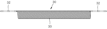
도 1은 종래의 형상기억합금 스프링 제조공정을 설명하기 위한 예시도이고, 도 2는 종래의 형상기억합금 스프링 제조공정으로 제조된 형상기억합금 스프링을 나타낸 예시도이다.FIG. 1 is an exemplary view for explaining a conventional shape memory alloy spring manufacturing process, and FIG. 2 is an illustration showing an example of a shape memory alloy spring manufactured by a conventional shape memory alloy spring manufacturing process.
도 1 및 도 2에서 보는 바와 같이, 종래에는 형상기억합금 와이어(10)가 봉(20)에 코일 형상으로 감기고, 감겨진 형상기억합금 와이어(10)가 열처리된 후, 일정 길이로 절단되어 형상기억합금 스프링(30)으로 제조된다. As shown in FIGS. 1 and 2, a shape
그러나, 이러한 방식에서는 요구되는 형상기억합금 스프링(30)의 길이 이상의 길이로 형상기억합금 와이어(10)가 봉(20)에 감기고, 이후 절단하여 요구되는 길이의 형상기억합금 스프링(30)을 얻게 된다. In this method, however, the shape
그런데, 이 경우, 양단에서 얻어지는 형상기억합금 스프링(A)은 일단부에는 필요한 길이의 연결부(31)가 형성될 수 있지만 타단부에는 필요한 길이의 연결부가 형성되지 못하는 문제점이 있다. 뿐만 아니라, 중간 부분(B)에서 얻어지는 형상기억합금 스프링(30)은 양단부에서 필요한 길이의 연결부(32)를 얻을 수 없는 문제점이 발생하게 된다. 즉, 도 2에서 보는 바와 같이, 중간부분(B)에서 얻어지는 형상기억합금 스프링(30)은 코일형태에서 절단되어 얻어지기 때문에, 몸체부(33)의 양단부에는 필요한 길이의 연결부(32)가 형성되지 못한다. 그리고 이와 같은 필요한 길이를 가지지 못하는 연결부는 인공근육 조립 공정에서 형상기억합금 스프링의 조립을 어렵게 하는 문제점이 될 수 있다.However, in this case, the shape memory alloy springs A obtained at both ends may have a connecting
양단부에 충분히 긴 길이를 가지는 연결부를 형성하기 위하여, 봉(20)에 하나의 스프링 단위로 형상기억합금 와이어를 감아서 형상기억합금 스프링을 얻을 수도 있지만, 이러한 방식은 대량의 형상기억합금 스프링을 얻기 위해서는 적합하지 않다. 또한, 봉(20)에 형상기억합금 와이어를 감는 작업이 사람에 의한 수작업으로 진행되고 있어 이러한 작업 환경을 개선하는 것도 무엇보다 필요한 실정이다.In order to form a connection portion having a sufficiently long length at both ends, a shape memory alloy spring can be obtained by winding a shape memory alloy wire in a single spring unit on the
상기와 같은 문제점을 해결하기 위하여, 본 발명이 이루고자 하는 기술적 과제는 연결부를 가지는 형상기억합금 스프링을 연속적으로 형성하여 대량으로 생산할 수 있는 형상기억합금 스프링의 연속 제조장치, 형상기억합금 스프링의 연속 제조방법 및 이에 의해 제조되는 형상기억합금 스프링을 제공하는 것이다.In order to solve the above problems, the present invention has been made to solve the above-mentioned problems occurring in the prior art, and it is an object of the present invention to provide an apparatus for continuously manufacturing a shape memory alloy spring capable of continuously forming a shape memory alloy spring having a connection portion, And a shape memory alloy spring produced thereby.
본 발명이 이루고자 하는 기술적 과제는 이상에서 언급한 기술적 과제로 제한되지 않으며, 언급되지 않은 또 다른 기술적 과제들은 아래의 기재로부터 본 발명이 속하는 기술 분야에서 통상의 지식을 가진 자에게 명확하게 이해될 수 있을 것이다.It is to be understood that both the foregoing general description and the following detailed description are exemplary and explanatory and are not intended to limit the invention to the precise form disclosed. There will be.
상기 기술적 과제를 달성하기 위하여, 본 발명의 일실시예는 감겨진 베이스 와이어가 풀리는 제1언와인딩부; 상기 제1언와인딩부에서 풀리는 상기 베이스 와이어가 관통 공급되는 제1관통공을 가지고, 상기 제1관통공의 중심축을 중심으로 회전하는 제1회전부; 상기 제1회전부에 구비되어 상기 제1회전부와 함께 회전하고, 감겨진 형상기억합금 와이어가 풀리면서 상기 제1회전부를 통과하여 공급되는 상기 베이스 와이어의 외주면에 감겨 복수의 단위 스프링 형상이 연속적으로 형성되도록 하는 제2언와인딩부; 상기 제2언와인딩부에서 풀리는 형상기억합금 와이어의 전단부 및 후단부를 상기 제1회전부를 통과하여 공급되는 상기 베이스 와이어에 각각 결속시키고, 상기 베이스 와이어와 함께 이송되는 제1고정부 및 제2고정부; 그리고 상기 형상기억합금 와이어가 감긴 상태의 상기 베이스 와이어가 권취되는 제1와인딩부를 포함하는 형상기억합금 스프링의 연속 제조장치를 제공한다.According to an aspect of the present invention, there is provided a semiconductor device comprising: a first unwinding unit for winding a wound base wire; A first rotating part having a first through hole through which the base wire is fed through the first unwinding part and is rotated about a central axis of the first through hole; A plurality of unit spring shapes are continuously formed on the outer circumferential surface of the base wire, which is supplied through the first rotating portion, while the shape memory alloy wire wound on the first rotating portion is rotated together with the first rotating portion A second unwinding unit for allowing the first winding unit to rotate; Wherein a front end portion and a rear end portion of the shape memory alloy wire to be unwound by the second unwinding portion are respectively bound to the base wire supplied through the first rotation portion, government; And a first winding portion around which the base wire wound around the shape memory alloy wire is wound.
본 발명의 실시예에 있어서, 상기 제1회전부가 제1 회전속도 및 상기 제1 회전속도보다 느린 제2 회전속도로 교대로 회전되도록 상기 제1 회전부의 회전속도를 제어하는 제어부를 더 포함하며, 상기 제1 회전속도에서는 상기 형상기억합금 와이어가 상기 베이스 와이어에 제1피치로 감겨 상기 단위 스프링의 몸체부가 형성되고, 상기 제2 회전속도에서는 상기 형상기억합금 와이어가 상기 베이스 와이어에 상기 제1피치보다 큰 제2피치로 감겨 상기 단위 스프링의 몸체부의 양단부에 연결부가 형성될 수 있다.The control unit may further include a control unit for controlling the rotation speed of the first rotation unit such that the first rotation unit alternately rotates at a first rotation speed and a second rotation speed that is slower than the first rotation speed, Wherein the shape memory alloy wire is wound on the base wire at a first pitch to form a body portion of the unit spring at the first rotation speed and at the second rotation speed, A connecting portion may be formed at both ends of the body portion of the unit spring.
본 발명의 실시예에 있어서, 상기 제2언와인딩부는 상기 제1회전부의 중심축을 중심으로 하는 제1회전 및 상기 제1회전부의 반경 방향으로 구비되는 회전축을 중심으로 하는 제2회전을 동시에 할 수 있다.In the embodiment of the present invention, the second unwinding unit may simultaneously perform the first rotation about the center axis of the first rotation unit and the second rotation around the rotation axis provided in the radial direction of the first rotation unit have.
본 발명의 실시예에 있어서, 감겨진 코어 와이어가 풀리는 제3언와인딩부와, 상기 제3언와인딩부에서 풀리는 상기 코어 와이어가 관통 공급되는 제2관통공을 가지고, 상기 제2관통공의 축 방향을 중심으로 회전하는 제2회전부와, 상기 제2회전부에 구비되어 상기 제2회전부와 함께 회전하고, 감겨진 둘레 와이어가 풀리면서 상기 제2회전부를 통과하여 공급되는 상기 코어 와이어의 외주면에 감겨 상기 형상기억합금 와이어가 형성되도록 하는 제4언와인딩부와, 상기 제4언와인딩부에서 풀리는 둘레 와이어의 전단부 및 후단부를 상기 제2회전부를 통과하여 공급되는 상기 코어 와이어에 각각 결속시키고, 상기 코어 와이어와 함께 이송되는 제3고정부 및 제4고정부를 가지는 와이어 제조부를 더 포함하고, 상기 둘레 와이어가 감긴 상태의 상기 코어 와이어는 제2와인딩부에 권취될 수 있다.In the embodiment of the present invention, the core wire has a third unwinding portion to which the wound core wire is unwound, and a second through hole through which the core wire is fed through the third unwinding portion, And a second rotation part provided on the second rotation part and rotated together with the second rotation part to be wound on an outer circumferential surface of the core wire supplied through the second rotation part while being wound around the circumferential wire wound around the second rotation part, A fourth unwinding portion for allowing the shape memory alloy wire to be formed, and a front end portion and a rear end portion of the circumferential wire to be loosened in the fourth unwinding portion are bound to the core wire supplied through the second rotation portion, Further comprising a wire manufacturing section having a third fixing section and a fourth fixing section which are carried together with the core wire, wherein the core wire It may be wound around the winding part 2.
한편, 상기 기술적 과제를 달성하기 위하여, 본 발명의 일실시예는 a) 축 방향으로 관통 형성되는 제1관통공을 가지는 제1회전부가 회전되고, 제1언와인딩부에서 풀리는 베이스 와이어가 상기 제1관통공을 통해 공급되는 단계; b) 상기 제1회전부에 구비되어 상기 제1회전부와 함께 회전하는 제2언와인딩부에 감겨진 형상기억합금 와이어가 풀리고, 상기 형상기억합금 와이어의 전단부가 제1고정부에 의해 상기 제1관통공을 통과해 공급되는 상기 베이스 와이어에 결속되는 단계; c) 상기 제2언와인딩부에서 풀리는 형상기억합금 와이어가 상기 제1회전부를 통과하여 공급되는 상기 베이스 와이어의 외주면에 감겨 복수의 단위 스프링 형상이 연속적으로 형성되는 단계; d) 상기 복수의 단위 스프링의 형상 풀림이 방지되도록, 상기 제2언와인딩부에서 풀리는 형상기억합금 와이어의 후단부가 제2고정부에 의해 상기 제1회전부를 통과하여 공급되는 상기 베이스 와이어에 결속되는 단계; 그리고 e) 제1와인딩부에 권취된 상기 형상기억합금 와이어가 감긴 상태의 상기 베이스 와이어가 상기 제1와인딩부에서 분리되는 단계를 포함하는 형상기억합금 스프링의 연속 제조방법을 제공한다.According to another aspect of the present invention, there is provided a method of manufacturing a semiconductor device, comprising the steps of: a) rotating a first rotating part having a first through hole penetrating in an axial direction; 1 through a through hole; b) a shape memory alloy wire wound around a second unwinding portion provided in the first rotation portion and rotating together with the first rotation portion is loosened, and a front end portion of the shape memory alloy wire is connected to the first through- Bonding to the base wire supplied through the ball; c) a shape memory alloy wire that is unwound in the second unwinding portion is wound on an outer circumferential surface of the base wire supplied through the first rotating portion to form a plurality of unit spring shapes continuously; d) a rear end of the shape memory alloy wire that is unwound in the second unwinding portion is coupled to the base wire supplied through the first rotation portion by the second fixing portion so that the shape release of the plurality of unit springs is prevented step; And e) the base wire wound with the shape memory alloy wire wound around the first winding part is separated from the first winding part.
본 발명의 실시예에 있어서, 상기 e) 단계 이후에, 상기 형상기억합금 와이어가 감긴 상태의 상기 베이스 와이어가 고온로에서 가열되어 스프링 형상으로 기억되도록 열처리되는 열처리 단계 및 상기 베이스 와이어가 제거되고 몸체부 및 연결부를 포함하는 복수의 개별 단위의 형상기억합금 스프링을 얻는 스프링 획득 단계를 더 포함할 수 있다. In the embodiment of the present invention, after the step (e), a heat treatment step in which the base wire wound with the shape memory alloy wire is heat-treated so as to be heated at a high temperature and stored in a spring shape, And a spring obtaining step of obtaining a plurality of individual units of shape memory alloy springs including a part and a connecting part.
본 발명의 실시예에 있어서, 상기 열처리 단계 및 상기 스프링 획득 단계의 사이에, 상기 열처리된 상기 형상기억합금 와이어 및 상기 베이스 와이어가 커팅되는 단계가 더 포함되고, 상기 커팅은 각각의 상기 연결부의 중앙 지점에서 이루어질 수 있다.In the embodiment of the present invention, further comprising the step of cutting the heat treated shape memory alloy wire and the base wire between the heat treatment step and the spring obtaining step, the cutting being performed at a center of each connecting portion .
본 발명의 실시예에 있어서, 상기 제2언와인딩부에서 풀리는 형상기억합금 와이어는 축 방향으로 관통 형성되는 제2관통공을 가지는 제2회전부가 회전되고, 제3언와인딩부에서 풀리는 코어 와이어가 상기 제2관통공을 통해 공급되는 단계와, 상기 제2회전부에 구비되어 상기 제2회전부와 함께 회전하는 제4언와인딩부에 감겨진 둘레 와이어가 풀리고, 상기 둘레 와이어의 전단부가 제3고정부에 의해 상기 제2관통공을 통과해 공급되는 상기 코어 와이어에 결속되는 단계와, 상기 제4언와인딩부에서 풀리는 상기 둘레 와이어가 상기 제2회전부를 통과하여 공급되는 상기 코어 와이어의 외주면에 감기는 단계와, 상기 둘레 와이어의 풀림이 방지되도록, 상기 제4언와인딩부에서 풀리는 둘레 와이어의 후단부가 제4고정부에 의해 상기 제2회전부를 통과하여 공급되는 상기 코어 와이어에 결속되는 단계를 통해 제조될 수 있다.In the embodiment of the present invention, the shape memory alloy wire that is unwound in the second unwinding portion is rotated in a second rotation part having a second through hole formed in the axial direction, and the core wire wound in the third unwinding part Wherein the first wire is fed through the second through hole and the circumferential wire wound around a fourth unwinding portion provided in the second rotating portion and rotating together with the second rotating portion is loosened, The core wire being wound on the outer circumferential surface of the core wire supplied through the second rotating portion and being wound by the fourth unwinding portion; And a rear end of the circumferential wire that is loosened in the fourth unwinding portion passes through the second rotation portion by the fourth fixing portion so that the circumferential wire is prevented from being loosened Class can be prepared by the steps which binds to the core wire.
한편, 상기 기술적 과제를 달성하기 위하여, 본 발명의 일실시예는 형상기억합금 스프링의 연속 제조방법으로 제조되는 형상기억합금 스프링을 제공한다.According to an aspect of the present invention, there is provided a shape memory alloy spring manufactured by a method for continuously manufacturing a shape memory alloy spring.
본 발명의 실시예에 있어서, 상기 형상기억합금 와이어는 코어 와이어 및 상기 코어 와이어에 감기는 둘레 와이어를 가지며, 상기 코어 와이어 및 상기 둘레 와이어는 형상기억합금일 수 있다.In an embodiment of the present invention, the shape memory alloy wire has a core wire and a circumferential wire wound around the core wire, and the core wire and the circumferential wire may be a shape memory alloy.
본 발명의 실시예에 있어서, 상기 형상기억합금 와이어는 코어 와이어 및 상기 코어 와이어에 감기는 둘레 와이어를 가지며, 상기 코어 와이어는 형상기억합금이고, 상기 둘레 와이어는 상기 코어 와이어에 열을 공급하기 위한 저항 소재로 형성될 수 있다.In an embodiment of the present invention, the shape memory alloy wire has a core wire and a circumferential wire wound around the core wire, the core wire is a shape memory alloy, and the circumferential wire Resistance material.
본 발명의 실시예에 있어서, 상기 코어 와이어 및 상기 둘레 와이어의 사이에는 상기 둘레 와이어와 상기 코어 와이어를 전기적으로 절연시키는 절연층이 더 마련될 수 있다.In an embodiment of the present invention, an insulating layer may be further provided between the core wire and the circumferential wire to electrically insulate the circumferential wire from the core wire.
본 발명의 실시예에 따르면, 제1회전부의 회전속도가 제어되어 베이스 와이어에 감기는 형상기억합금 와이어의 피치가 조절될 수 있다. 이를 통해, 형상기억합금 와이어의 몸체부 및 연결부를 용이하게 형성할 수 있으며, 복수의 형상기억합금 스프링이 연속적으로 형성될 수 있다.According to the embodiment of the present invention, the pitch of the shape memory alloy wire wound around the base wire can be adjusted by controlling the rotational speed of the first rotating portion. As a result, the body portion and the connecting portion of the shape memory alloy wire can be easily formed, and a plurality of shape memory alloy springs can be continuously formed.
본 발명의 효과는 상기한 효과로 한정되는 것은 아니며, 본 발명의 상세한 설명 또는 청구범위에 기재된 발명의 구성으로부터 추론 가능한 모든 효과를 포함하는 것으로 이해되어야 한다.It should be understood that the effects of the present invention are not limited to the effects described above, but include all effects that can be deduced from the description of the invention or the composition of the invention set forth in the claims.
도 1은 종래의 형상기억합금 스프링 제조공정을 설명하기 위한 예시도이다.
도 2는 종래의 형상기억합금 스프링 제조공정으로 제조된 형상기억합금 스프링을 나타낸 예시도이다.
도 3 내지 도 5는 본 발명의 제1실시예에 따른 형상기억합금 스프링의 연속 제조장치를 나타낸 예시도이다.
도 6은 본 발명의 제1실시예에 따른 형상기억합금 스프링의 연속 제조장치의 제1회전부를 중심으로 나타낸 예시도이다.
도 7은 본 발명의 제1실시예에 따른 형상기억합금 스프링의 연속 제조방법을 나타낸 흐름도이다.
도 8은 본 발명의 제1실시예에 따른 형상기억합금 스프링을 나타낸 예시도이다.
도 9 및 도 10은 본 발명의 제2실시예에 따른 형상기억합금 스프링의 연속 제조장치의 와이어 제조부를 나타낸 예시도이다.
도 11 및 도 12는 본 발명의 제2실시예에 따른 형상기억합금 스프링의 형상기억합금 와이어를 나타낸 단면예시도이다.FIG. 1 is an exemplary view for explaining a conventional shape memory alloy spring manufacturing process. FIG.
Fig. 2 is an illustration showing an example of a shape memory alloy spring manufactured by a conventional shape memory alloy spring manufacturing process.
FIGS. 3 to 5 are views illustrating an apparatus for continuously manufacturing a shape memory alloy spring according to a first embodiment of the present invention. FIG.
6 is an exemplary view showing the first rotating portion of the apparatus for continuously manufacturing a shape memory alloy spring according to the first embodiment of the present invention.
7 is a flowchart showing a method for continuously manufacturing a shape memory alloy spring according to the first embodiment of the present invention.
8 is an exemplary view showing a shape memory alloy spring according to a first embodiment of the present invention.
FIGS. 9 and 10 are views showing examples of a wire manufacturing section of the apparatus for continuously manufacturing a shape memory alloy spring according to a second embodiment of the present invention.
11 and 12 are cross-sectional illustrations of a shape memory alloy wire of a shape memory alloy spring according to a second embodiment of the present invention.
이하에서는 첨부한 도면을 참조하여 본 발명을 설명하기로 한다. 그러나 본 발명은 여러 가지 상이한 형태로 구현될 수 있으며, 따라서 여기에서 설명하는 실시예로 한정되는 것은 아니다. 그리고 도면에서 본 발명을 명확하게 설명하기 위해서 설명과 관계없는 부분은 생략하였으며, 명세서 전체를 통하여 유사한 부분에 대해서는 유사한 도면 부호를 붙였다.DETAILED DESCRIPTION OF THE PREFERRED EMBODIMENTS Hereinafter, the present invention will be described with reference to the accompanying drawings. The present invention may, however, be embodied in many different forms and should not be construed as limited to the embodiments set forth herein. In order to clearly illustrate the present invention, parts not related to the description are omitted, and similar parts are denoted by like reference characters throughout the specification.
명세서 전체에서, 어떤 부분이 다른 부분과 “연결(접속, 접촉, 결합)”되어 있다고 할 때, 이는 “직접적으로 연결”되어 있는 경우뿐 아니라, 그 중간에 다른 부재를 사이에 두고 “간접적으로 연결”되어 있는 경우도 포함한다. 또한 어떤 부분이 어떤 구성요소를 “포함”한다고 할 때, 이는 특별히 반대되는 기재가 없는 한 다른 구성요소를 제외하는 것이 아니라 다른 구성요소를 더 구비할 수 있다는 것을 의미한다.Throughout the specification, when a part is referred to as being "connected" (connected, connected, coupled) with another part, it is not only the case where it is "directly connected" "Is included. Also, when an element is referred to as " comprising ", it means that it can include other elements, not excluding other elements unless specifically stated otherwise.
본 명세서에서 사용한 용어는 단지 특정한 실시예를 설명하기 위해 사용된 것으로, 본 발명을 한정하려는 의도가 아니다. 단수의 표현은 문맥상 명백하게 다르게 뜻하지 않는 한, 복수의 표현을 포함한다. 본 명세서에서, “포함하다” 또는 “가지다” 등의 용어는 명세서상에 기재된 특징, 숫자, 단계, 동작, 구성요소, 부품 또는 이들을 조합한 것이 존재함을 지정하려는 것이지, 하나 또는 그 이상의 다른 특징들이나 숫자, 단계, 동작, 구성요소, 부품 또는 이들을 조합한 것들의 존재 또는 부가 가능성을 미리 배제하지 않는 것으로 이해되어야 한다.The terminology used herein is for the purpose of describing particular embodiments only and is not intended to be limiting of the invention. The singular expressions include plural expressions unless the context clearly dictates otherwise. In this specification, the terms "comprises" or "having" and the like refer to the presence of stated features, integers, steps, operations, elements, components, or combinations thereof, But do not preclude the presence or addition of one or more other features, integers, steps, operations, elements, components, or combinations thereof.
이하 첨부된 도면을 참고하여 본 발명의 실시예를 상세히 설명하기로 한다.Hereinafter, embodiments of the present invention will be described in detail with reference to the accompanying drawings.
도 3 내지 도 5는 본 발명의 제1실시예에 따른 형상기억합금 스프링의 연속 제조장치를 나타낸 예시도이고, 도 6은 본 발명의 제1실시예에 따른 형상기억합금 스프링의 연속 제조장치의 제1회전부를 중심으로 나타낸 예시도이다.FIGS. 3 to 5 are views showing an apparatus for continuously manufacturing a shape memory alloy spring according to a first embodiment of the present invention, and FIG. 6 is a sectional view of the apparatus for continuously manufacturing a shape memory alloy spring according to the first embodiment of the present invention. Fig. 8 is an exemplary view showing the first rotating portion as a center.
도 3 내지 도 6에서 보는 바와 같이, 형상기억합금 스프링의 연속 제조장치는 제1언와인딩(Unwinding)부(110), 제1회전부(120), 제2언와인딩(Unwinding)부(130), 제1고정부(140), 제2고정부(150) 그리고 제1와인딩(Winding)부(160)를 포함할 수 있다. 3 to 6, the apparatus for continuously manufacturing a shape memory alloy spring includes a first
제1언와인딩부(110)에서는 감겨진 베이스 와이어(210)가 풀릴 수 있다. 베이스 와이어(210)는 제조하고자 하는 형상기억합금 스프링의 내측지름에 대응되는 외측지름을 가질 수 있다. 베이스 와이어(210)는 합성 수지 소재의 끈일 수 있으나 이에 한정되는 것은 아니며 금속 소재의 선재 등 다양한 소재가 사용될 수 있다.In the first
제1언와인딩부(110)에서 풀리는 베이스 와이어(210)는 제1와인딩부(160)에 권취될 수 있다. 그리고 베이스 와이어(210)는 등속으로 공급될 수 있다. The
제1회전부(120)는 제1언와인딩부(110)에서 풀리는 베이스 와이어(210)의 공급 방향으로 구비될 수 있다. 제1회전부(120)에는 중심 방향으로 제1관통공(121)이 관통 형성될 수 있다. 제1관통공(121)으로는 베이스 와이어(210)가 관통되어 공급될 수 있으며, 제1관통공(121)은 베이스 와이어(210)의 외측 지름보다 큰 내측 지름을 가질 수 있다.The
제1회전부(120)는 제1지지부(170)에 회전 가능하도록 결합될 수 있다. 제1지지부(170)는 제1언와인딩부(110)에서 풀리는 베이스 와이어(210)의 공급 방향에 구비될 수 있다. 제1지지부(170)에는 베이스 와이어(210)의 공급 방향으로 제1연결공(171)이 관통 형성될 수 있다. 제1회전부(120)는 제1지지부(170)에 회전 가능하도록 결합될 수 있으며, 제1관통공(121)이 제1연결공(171)과 동일한 중심축을 가지도록 마련될 수 있다. 제1회전부(120)는 제1지지부(170)에 결합되어 제1관통공(121)의 중심축을 중심으로 회전할 수 있다.The
제2언와인딩부(130)는 제1회전부(120)의 외주면에 구비될 수 있다. 제2언와인딩부(130)는 제1회전부(120)의 반경 방향으로 구비되는 회전축(131)을 중심으로 회전 가능하게 구비될 수 있다. 따라서, 제2언와인딩부(130)는 제1회전부(120)의 회전 시에 제1회전부(120)와 함께 회전될 수 있으며, 제2언와인딩부(130) 자체가 회전될 수도 있다. 즉, 제2언와인딩부(130)는 제1회전부(120)의 중심축을 중심으로 하는 제1회전 및 제1회전부(120)의 반경 방향으로 구비되는 회전축(131)을 중심으로 하는 제2회전을 동시에 할 수 있다.The
제2언와인딩부(130)에서는 형상기억합금 와이어(220)가 풀릴 수 있다. 제2언와인딩부(130)에서 풀리는 형상기억합금 와이어(220)는 제1언와인딩부(110)에서 풀린 후 제1회전부(120)의 제1관통공(121)을 통과하여 공급되는 베이스 와이어(210)의 외주면에 감길 수 있다. 형상기억합금 와이어(220)는 단일의 선재일 수 있다. 형상기억합금 와이어(220)는 형상기억합금 스프링의 선재를 형성할 수 있으며, 형상기억합금 스프링의 선재의 지름은 형상기억합금 와이어(220)의 지름일 수 있다.In the
제1고정부(140)는 제2언와인딩부(130)에서 풀리는 형상기억합금 와이어(220)의 전단부를 제1회전부(120)를 통과하여 공급되는 베이스 와이어(210)에 결속시킬 수 있다. 제1고정부(140)는 형상기억합금 와이어(220)를 베이스 와이어(210)에 결속시킨 상태로 고정될 수 있으며, 베이스 와이어(210)가 공급됨에 따라 이동될 수 있다. 제1고정부(140)는 클립 형태를 가지거나 집게 형태를 가질 수 있다. 제1고정부(140)는 형상기억합금 와이어(220)의 전단부가 형상기억합금 스프링(400, 도 8 참조)의 연결부(420, 도 8 참조)를 형성할 수 있는 길이(221)만큼 확보되도록 결합될 수 있다.The
본 명세서에서 형상기억합금 와이어(220)의 전단부 및 후단부는 형상기억합금 와이어(220)의 공급 방향을 기준으로 한다.In the present specification, the front end and the rear end of the shape
제2언와인딩부(130)에서 풀리는 형상기억합금 와이어(220)의 전단부가 제1고정부(140)에 의해 베이스 와이어(210)에 결속된 상태에서 베이스 와이어(210)가 계속 공급되고 제1회전부(120)가 회전됨에 따라, 형상기억합금 와이어(220)는 베이스 와이어(210)의 외주면에 베이스 와이어(210)의 길이방향을 따라 감길 수 있다. 그리고, 형상기억합금 와이어(220)가 베이스 와이어(210)에 감기는 상태에서 베이스 와이어(210)의 공급이 계속됨에 따라 제2언와인딩부(130)가 회전되면서 형상기억합금 와이어(220)는 지속적으로 풀릴 수 있게 된다.The
형상기억합금 스프링의 연속 제조장치는 제어부(180)를 포함할 수 있다. 제어부(180)는 제1회전부(120)의 회전속도를 제어할 수 있다. 제어부(180)는 제1회전부(120)를 제1회전속도로 회전시킬 수 있으며, 제1회전부(120)가 제1회전속도로 회전되면 형상기억합금 와이어(220)는 베이스 와이어(210)에 제1피치(P1)로 감길 수 있다. 제1피치(P1)로 감기는 형상기억합금 와이어(220)는 형상기억합금 스프링(400)의 몸체부(410, 도 8 참조)를 형성할 수 있다. 그리고, 제어부(180)는 제1회전부(120)를 제1회전속도보다 느린 제2회전속도로 회전시킬 수 있다. 제1회전부(120)가 제2회전속도로 회전되면 형상기억합금 와이어(220)는 베이스 와이어(210)에 제1피치(P1)보다 큰 제2피치(P2)로 감길 수 있다. 제2피치(P2)로 감기는 형상기억합금 와이어(220)는 형상기억합금 스프링(400)의 연결부(420)를 형성할 수 있다. The apparatus for continuous production of the shape memory alloy springs may include a
제어부(180)는 제1회전부(120)가 제1회전속도 및 제2회전속도로 반복하여 회전되도록 제어할 수 있다. 이를 통해, 베이스 와이어(210)에는 복수의 단위 스프링 형상, 즉 복수의 형상기억합금 스프링이 연속적으로 형성될 수 있다.The
형상기억합금 와이어(220)가 감긴 상태의 베이스 와이어(210)는 제1와인딩부(160)에 권취될 수 있다. The
제어부(180)는 제1회전속도를 조절하여 제1피치(P1)를 조절할 수 있으며, 이를 통해, 형상기억합금 스프링(400)의 몸체부(410)의 권수, 즉, 형상기억합금 스프링(400)의 유효 권수를 조절할 수 있다. 또한, 제어부(180)는 제1회전부(120)가 제1회전속도로 회전되는 회전 지속 시간을 조절할 수 있으며, 이를 통해, 형상기억합금 스프링(400)의 몸체부(410)의 길이가 조절될 수 있다.The
그리고, 제어부(180)는 제2회전속도를 조절하여 제2피치(P2)를 조절할 수 있으며, 이를 통해, 형상기억합금 스프링(400)의 연결부(420)의 권수를 조절 수 있다. 본 실시예에서, 제어부(180)는 연결부(420)가 직선 형태에 가깝게 형성될 수 있도록, 제2피치(P2)가 크게 형성되도록 제2회전속도를 조절함이 바람직하다. 다만, 연결부(420) 구간에서 형상기억합금 와이어(220)가 베이스 와이어(210)에 감기지 않는 경우 제2언와인딩부(130)에서 형상기억합금 와이어(220)의 풀림이 이루이지지 않을 수 있기 때문에, 제2언와인딩부(130)에서 형상기억합금 와이어(220)의 풀림이 이루어질 수 있도록 하는 최소한의 감김은 유지되도록 함이 바람직하다. 제어부(180)는 제1회전부(120)가 제2회전속도로 회전되는 회전 지속 시간을 조절할 수 있으며, 이를 통해, 형상기억합금 스프링(400)의 연결부(420)의 길이가 조절될 수 있다.The
제2고정부(150)는 제2언와인딩부(130)에서 풀리는 형상기억합금 와이어(220)의 후단부를 제1회전부(120)를 통과하여 공급되는 베이스 와이어(210)에 결속시킬 수 있다. 제2고정부(150)는 제1고정부(140)와 동일한 것일 수 있으며, 베이스 와이어(210)와 함께 이송될 수 있다. 제2고정부(150)는 형상기억합금 와이어(220)의 후단부가 형상기억합금 스프링(400)의 연결부(420)를 형성할 수 있는 길이(223)만큼 확보되도록 결합될 수 있다(도 5 참조). The
제1고정부(140) 및 제2고정부(150)는 베이스 와이어(210)에 감긴 형상기억합금 와이어(220)의 전단부 및 후단부에 각각 결속될 수 있으며, 이를 통해, 베이스 와이어(210)에 감긴 형상기억합금 와이어(220)의 풀림이 방지될 수 있다. The
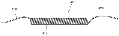
도 7은 본 발명의 제1실시예에 따른 형상기억합금 스프링의 연속 제조방법을 나타낸 흐름도이고, 도 8은 본 발명의 제1실시예에 따른 형상기억합금 스프링을 나타낸 예시도이다.FIG. 7 is a flowchart showing a method for continuously manufacturing a shape memory alloy spring according to a first embodiment of the present invention, and FIG. 8 is an illustration showing an example of a shape memory alloy spring according to the first embodiment of the present invention.
도 3 내지 도 6과 함께 도 7 및 도 8을 더 포함하여 보는 바와 같이, 형상기억합금 스프링의 연속 제조방법은 축 방향으로 관통 형성되는 제1관통공(121)을 가지는 제1회전부(120)가 회전되고, 제1언와인딩부(110)에서 풀리는 베이스 와이어(210)가 제1관통공(121)을 통해 공급되는 단계(S310)를 포함할 수 있다. 7 and 8 together with FIGS. 3 to 6, a continuous manufacturing method of a shape memory alloy spring includes a
S310 단계에서 제1언와인딩부(110)에서 풀리는 베이스 와이어(210)는 제1회전부(120)를 통과하여 공급되어 제1와인딩부(160)에 감길 수 있다. In operation S310, the
그리고, 형상기억합금 스프링의 연속 제조방법은 제1회전부(120)에 구비되어 제1회전부(120)와 함께 회전하는 제2언와인딩부(130)에 감겨진 형상기억합금 와이어(220)가 풀리고, 형상기억합금 와이어(220)의 전단부가 제1고정부(140)에 의해 제1관통공(121)을 통과해 공급되는 베이스 와이어(210)에 결속되는 단계(S320)를 포함할 수 있다. In the continuous manufacturing method of the shape memory alloy spring, the shape
S320 단계에서, 형상기억합금 와이어(220)는 변형온도를 넓은 범위에서 제어할 수 있고 변형량이 크며, 수축시에 많은 반복 동작이 작용한 이후에도 형상기억효과 능력이 거의 변화하지 않는 장점을 가지는 Ti-Ni 합금, Cu-Ti합금을 포함할 수 있다. In step S320, the shape
또한, 형상기억합금 스프링의 연속 제조방법은 제2언와인딩부(130)에서 풀리는 형상기억합금 와이어(220)가 제1회전부(120)를 통과하여 공급되는 베이스 와이어(210)의 외주면에 감겨 복수의 단위 스프링 형상이 연속적으로 형성되는 단계(S330)를 포함할 수 있다.Further, in the continuous manufacturing method of the shape memory alloy spring, the shape
S330 단계에서, 단위 스프링은 형상기억합금 스프링(400)일 수 있다. 형상기억합금 스프링(400)은 몸체부(410) 및 연결부(420)를 가질 수 있다. 몸체부(410)는 형상기억합금 스프링(400)에서 변형이 발생되는 부분일 수 있다. 그리고, 연결부(420)는 몸체부(410)의 양단부에 형성되어 인공근육 장치의 해당 구성과 결합되는 기능을 수행할 수 있다. S330 단계에서 제1회전부(120)는 제어부(180)에 의해 회전속도 및 회전 시간이 조절될 수 있으며, 이를 통해, 몸체부(410) 및 연결부(420)의 피치 및 길이가 조절될 수 있다.In step S330, the unit spring may be the shape
형상기억합금 스프링의 연속 제조방법은 복수의 단위 스프링의 형상 풀림이 방지되도록, 제2언와인딩부(130)에서 풀리는 형상기억합금 와이어(220)의 후단부가 제2고정부(150)에 의해 제1회전부(120)를 통과하여 공급되는 베이스 와이어(210)에 결속되는 단계(S340)를 포함할 수 있다.The continuous manufacturing method of the shape memory alloy spring is such that the rear end of the shape
S340 단계에서 제2고정부(150)의 마련은 베이스 와이어(210)에 형상기억합금 와이어(220)를 감는 공정이 완료되는 시점에서 이루어질 수 있다. 제2고정부(150)에 의해 형상기억합금 와이어(220)의 후단부가 베이스 와이어(210)에 결속되면, 형상기억합금 와이어(220)는 베이스 와이어(210)에서 풀리지 않도록 고정될 수 있다.In step S340, the
그리고, 형상기억합금 스프링의 연속 제조방법은 제1와인딩부(160)에 권취된 형상기억합금 와이어(220)가 감긴 상태의 베이스 와이어(210)가 제1와인딩부(160)에서 분리되는 단계(S350)를 포함할 수 있다.The method for continuously manufacturing the shape memory alloy spring includes a step of separating the
제1와인딩부(160)에서 분리된 베이스 와이어(210)에는 형상기억합금 와이어(220), 제1고정부(140) 및 제2고정부(150)가 결합된 상태일 수 있다. The shape
또한, 형상기억합금 스프링의 연속 제조방법은 형상기억합금 와이어(220)가 감긴 상태의 베이스 와이어(210)가 고온로에서 가열되어 스프링 형상으로 기억되도록 열처리되는 열처리 단계(S360) 및 베이스 와이어(210)가 제거되고 몸체부(410) 및 연결부(420)를 포함하는 복수의 개별 단위의 형상기억합금 스프링을 얻는 스프링 획득 단계(S370)를 더 포함할 수 있다.In the continuous manufacturing method of the shape memory alloy spring, a heat treatment step (S360) in which the base wire (210) in a state where the shape memory alloy wire (220) is wound is heated at a high temperature to be stored in a spring shape, (S370) to obtain a plurality of individual unit shape memory alloy springs including the body portion (410) and the connection portion (420).
S360 단계에서, 형상기억합금 와이어(220)가 감긴 상태의 베이스 와이어(210)는 고온로에서 300~400℃의 온도에서 30~60분 동안 열처리될 수 있다. 이를 통해, 형상기억합금 스프링(400)이 신장된 상태에서 형상기억합금 스프링(400)에 300~400℃의 온도가 적용되면, 형상기억합금 스프링(400)은 수축되어 초기형태로 돌아올 수 있다. 열처리 공정이 완료되면, 제1고정부(140), 제2고정부(150) 및 베이스 와이어(210)는 제거될 수 있다. In step S360, the
더하여, 형상기억합금 스프링의 연속 제조방법은 S360 단계 및 S370 단계의 사이에, 열처리된 형상기억합금 와이어 및 베이스 와이어가 커팅되는 단계(S365)를 더 포함할 수 있다. S365 단계에서, 커팅은 형상기억합금 와이어(220)가 감긴 상태의 베이스 와이어(210)에 대해 이루어질 수 있다. 즉, 형상기억합금 와이어(220)가 감긴 상태에서 베이스 와이어(210) 및 형상기억합금 와이어(220)는 커팅될 수 있다. 그리고, 커팅은 각각의 연결부(420)의 중앙 지점에서 이루어질 수 있다. In addition, the continuous manufacturing method of the shape memory alloy spring may further include a step (S365) of cutting the heat treated shape memory alloy wire and the base wire between S360 and S370. In step S365, cutting may be performed on the
도 9 및 도 10은 본 발명의 제2실시예에 따른 형상기억합금 스프링의 연속 제조장치의 와이어 제조부를 나타낸 예시도이고, 도 11 및 도 12는 본 발명의 제2실시예에 따른 형상기억합금 스프링의 형상기억합금 와이어를 나타낸 단면예시도이다. 본 실시예에서는 형상기억합금 와이어를 제조하기 위한 와이어 제조부가 더 포함될 수 있으며, 다른 구성은 전술한 제1실시예와 동일하므로 설명을 생략한다.FIGS. 9 and 10 are views showing an example of a wire manufacturing section of an apparatus for continuously manufacturing a shape memory alloy spring according to a second embodiment of the present invention. FIGS. 11 and 12 are views showing a shape memory alloy according to a second embodiment of the present invention Sectional view showing a shape memory alloy wire of a spring. In this embodiment, a wire manufacturing portion for manufacturing the shape memory alloy wire can be further included, and the other structure is the same as that of the above-described first embodiment, so the description is omitted.
먼저, 도 9 내지 도 11에서 바와 같이, 형상기억합금 스프링의 연속 제조장치는 와이어 제조부(500)를 더 포함할 수 있다. 9 to 11, the apparatus for continuously manufacturing the shape memory alloy springs may further include a
그리고, 와이어 제조부(500)는 제3언와인딩부(510), 제2회전부(520), 제4언와인딩부(530), 제3고정부(540), 제4고정부(550) 및 제2와인딩부(560)를 가질 수 있다.The
제3언와인딩부(510)에서는 감겨진 코어 와이어(230)가 풀릴 수 있다. 코어 와이어(230)는 형상기억합금일 수 있다. 그리고, 제3언와인딩부(510)에서 풀리는 코어 와이어(230)는 제2와인딩부(560)에 권취될 수 있다. 코어 와이어(230)는 단일의 선재일 수 있다.In the
제2회전부(520)는 제3언와인딩부(510)에서 풀리는 코어 와이어(230)의 공급 방향으로 구비될 수 있다. 제2회전부(520)에는 중심 방향으로 제2관통공(521)이 관통 형성될 수 있으며, 제2관통공(521)으로는 코어 와이어(230)가 관통 공급될 수 있다. 제2관통공(521)은 코어 와이어(230)의 외측 지름보다 큰 내측 지름을 가질 수 있다.The second
제2회전부(520)는 제2지지부(570)에 회전 가능하도록 결합될 수 있다. 제2지지부(570)는 제3언와인딩부(510)에서 풀리는 코어 와이어(230)의 공급 방향에 구비될 수 있다. 제2지지부(570)에는 코어 와이어(230)의 공급 방향으로 제2연결공(571)이 관통 형성될 수 있다. 제2회전부(520)는 제2지지부(570)에 회전 가능하도록 결합될 수 있으며, 제2관통공(521)이 제2연결공(571)과 동일한 중심축을 가지도록 마련될 수 있다. 제2회전부(520)는 제2지지부(570)에 결합되어 제2관통공(521)의 중심축을 중심으로 회전할 수 있다.The
제4언와인딩부(530)는 제2회전부(520)의 외주면에 구비될 수 있다. 제4언와인딩부(530)는 제2회전부(520)의 반경 방향으로 구비되는 회전축을 중심으로 회전 가능하게 구비될 수 있다. 제4언와인딩부(530)는 제2회전부(520)의 중심축을 중심으로 하는 제3회전 및 제2회전부(520)의 반경 방향으로 구비되는 회전축을 중심으로 하는 제4회전을 동시에 할 수 있다.The
제4언와인딩부(530)에서는 둘레 와이어(240)가 풀릴 수 있다. 제4언와인딩부(530)에서 풀리는 둘레 와이어(240)는 제3언와인딩부(510)에서 풀린 후 제2회전부(520)의 제2관통공(521)을 통과하여 공급되는 코어 와이어(230)의 외주면에 감길 수 있다. 본 실시예에서 형상기억합금 와이어(1220)는 코어 와이어(230)와 코어 와이어(230)의 외주면에 감기는 둘레 와이어(240)를 가질 수 있으며, 이를 통해, 형상기억합금 스프링은 더욱 강한 신장력 및 수축력을 발생시킬 수 있다.In the fourth unwinding
제3고정부(540)는 제4언와인딩부(530)에서 풀리는 둘레 와이어(240)의 전단부를 제2회전부(520)를 통과하여 공급되는 코어 와이어(230)에 결속시킬 수 있다. 제3고정부(540)는 둘레 와이어(240)를 코어 와이어(230)에 결속시킨 상태로 고정될 수 있으며, 코어 와이어(230)가 공급됨에 따라 이동될 수 있다. 제3고정부(540)는 클립 형태를 가지거나 집게 형태를 가질 수 있다.The
제4언와인딩부(530)에서 풀리는 둘레 와이어(240)의 전단부가 제3고정부(540)에 의해 코어 와이어(230)에 결속된 상태에서 코어 와이어(230)가 계속 공급되고 제2회전부(520)가 회전됨에 따라, 둘레 와이어(240)는 코어 와이어(230)의 외주면에 코어 와이어(230)의 길이방향을 따라 감길 수 있다. 그리고, 둘레 와이어(240)가 코어 와이어(230)에 감기는 상태에서 코어 와이어(230)의 공급이 계속됨에 따라 제4언와인딩부(530)가 회전되면서 둘레 와이어(240)는 지속적으로 풀릴 수 있게 된다. 둘레 와이어(240)가 감긴 상태의 코어 와이어(230)는 제2와인딩부(560)에 권취될 수 있다. The
제4고정부(550)는 제4언와인딩부(530)에서 풀리는 둘레 와이어(240)의 후단부를 제2회전부(520)를 통과하여 공급되는 코어 와이어(230)에 결속시킬 수 있다. 제4고정부(550)는 제3고정부(540)와 동일한 것일 수 있으며, 코어 와이어(230)와 함께 이송될 수 있다. 제3고정부(540) 및 제4고정부(550)는 코어 와이어(230)에 감긴 둘레 와이어(240)의 전단부 및 후단부에 각각 결속될 수 있으며, 이를 통해, 코어 와이어(230)에 감긴 둘레 와이어(240)의 풀림이 방지될 수 있다.The
본 실시예에서, 둘레 와이어(240)는 형상기억합금으로 이루어질 수 있다. 즉, 코어 와이어(230) 및 둘레 와이어(240)는 모두 형상기억합금으로 이루어질 수 있다. 이렇게 형성되는 형상기억합금 스프링은 외력에 의한 신장 후 열에 의한 수축 시에 더욱 신속하게 수축이 이루어질 수 있으며, 강한 수축력을 가질 수 있다.In this embodiment, the
또한, 둘레 와이어(240)는 저항 소재로 형성될 수 있다. 둘레 와이어(240)가 저항 소재로 형성되는 경우, 둘레 와이어(240)는 외부에서 공급되는 전류에 의하여 코어 와이어(230)보다 빠르게 가열될 수 있다. 그리고, 둘레 와이어(240)에 의하여 발생한 열은 코어 와이어(230)로 전달되어 코어 와이어(230)가 빠르게 가열될 수 있으며, 이를 통해, 코어 와이어(230)의 응답속도가 빨라질 수 있다. 둘레 와이어(240)는 코어 와이어(230)보다 저항이 높은 니켈크롬, 철크롬, 동니켈 및 콘스탄탄 중 선택되는 어느 하나 이상의 금속 재질로 이루어질 수 있다. 그리고 저술한 효과뿐만 아니라, 둘레 와이어(240)가 코어 와이어(230)에 감겨지게 되기 때문에, 형상기억합금 스프링의 강성은 증가될 수 있다. Also, the
그리고, 도 12에서 보는 바와 같이, 둘레 와이어(240)가 저항 소재로 형성되는 경우, 형상기억합금 와이어(2220)는 코어 와이어(230) 및 둘레 와이어(240)의 사이에는 절연층(250)을 더 가질 수 있다. 절연층(250)은 둘레 와이어(240) 및 코어 와이어(230)를 전기적으로 절연시킬 수 있다. 절연층(250)은 둘레 와이어(240)에 공급되는 전류가 코어 와이어(230)로 흐르지 않도록 하여 둘레 와이어(240)의 열 발생 효율이 감소되지 않도록 할 수 있다. 12, when the
절연층(250)은 둘레 와이어(240)에서 발생하는 고온에 견딜 수 있고, 둘레 와이어(240)에서 발생하는 열이 코어 와이어(230)로 효율적으로 전달될 수 있도록 하는 재질로 제작될 수 있다. 예를 들면, 절연층(250)은 600℃ 이상에서도 견딜 수 있는 유리 섬유, 테프론 등으로 제작될 수 있다. 코어 와이어(230)는 외주면에 절연층(250)이 코팅된 상태로 공급될 수 있다. The insulating
이러한 와이어 제조부(500)를 통해 제2언와인딩부(130)에서 풀리는 형상기억합금 와이어(220)의 제조 공정을 설명하면 다음과 같다.A manufacturing process of the shape
먼저, 축 방향으로 관통 형성되는 제2관통공(521)을 가지는 제2회전부(520)가 회전되고, 제3언와인딩부(510)에서 풀리는 코어 와이어(230)가 제2관통공(521)을 통해 공급되는 단계가 진행될 수 있다. 그리고, 제2회전부(520)에 구비되어 제2회전부(520)와 함께 회전하는 제4언와인딩부(530)에 감겨진 둘레 와이어(240)가 풀리고, 둘레 와이어(240)의 전단부가 제3고정부(540)에 의해 제2관통공(521)을 통과해 공급되는 코어 와이어(230)에 결속되는 단계가 진행될 수 있다. 이후, 제4언와인딩부(530)에서 풀리는 둘레 와이어(240)가 제2회전부(520)를 통과하여 공급되는 코어 와이어(230)의 외주면에 감기는 단계가 진행될 수 있다. 그리고 둘레 와이어(240)의 풀림이 방지되도록, 제4언와인딩부(530)에서 풀리는 둘레 와이어(240)의 후단부가 제4고정부(550)에 의해 제2회전부(520)를 통과하여 공급되는 코어 와이어(230)에 결속되는 단계가 진행될 수 있다. The second
전술한 본 발명의 설명은 예시를 위한 것이며, 본 발명이 속하는 기술분야의 통상의 지식을 가진 자는 본 발명의 기술적 사상이나 필수적인 특징을 변경하지 않고서 다른 구체적인 형태로 쉽게 변형이 가능하다는 것을 이해할 수 있을 것이다. 그러므로 이상에서 기술한 실시예들은 모든 면에서 예시적인 것이며 한정적이 아닌 것으로 이해해야만 한다. 예를 들어, 단일형으로 설명되어 있는 각 구성 요소는 분산되어 실시될 수도 있으며, 마찬가지로 분산된 것으로 설명되어 있는 구성 요소들도 결합된 형태로 실시될 수 있다.It will be understood by those skilled in the art that the foregoing description of the present invention is for illustrative purposes only and that those of ordinary skill in the art can readily understand that various changes and modifications may be made without departing from the spirit or essential characteristics of the present invention. will be. It is therefore to be understood that the above-described embodiments are illustrative in all aspects and not restrictive. For example, each component described as a single entity may be distributed and implemented, and components described as being distributed may also be implemented in a combined form.
본 발명의 범위는 후술하는 청구범위에 의하여 나타내어지며, 청구범위의 의미 및 범위 그리고 그 균등 개념으로부터 도출되는 모든 변경 또는 변형된 형태가 본 발명의 범위에 포함되는 것으로 해석되어야 한다.The scope of the present invention is defined by the appended claims, and all changes or modifications derived from the meaning and scope of the claims and their equivalents should be construed as being included within the scope of the present invention.
110: 제1언와인딩부
120: 제1회전부
130: 제2언와인딩부
140: 제1고정부
150: 제2고정부
160: 제1와인딩부
170: 제1지지부
180: 제어부
210: 베이스 와이어
220,1220,2220: 형상기억합금 와이어
230: 코어 와이어
240: 둘레 와이어
250: 절연층
400: 형상기억합금 스프링
410: 몸체부
420: 연결부
500: 와이어 제조부110: first unwinding part
120: first rotating part
130: second unwinding part
140: first fixing unit
150: second fixing portion
160: First winding part
170: first support portion
180:
210: Base wire
220, 1220, 2220: Shape memory alloy wire
230: core wire
240: circumferential wire
250: insulating layer
400: shape memory alloy spring
410:
420:
500: wire manufacturing section
Claims (12)
상기 제1언와인딩부에서 풀리는 상기 베이스 와이어가 관통 공급되는 제1관통공을 가지고, 상기 제1관통공의 중심축을 중심으로 회전하는 제1회전부;
상기 제1회전부에 구비되어 상기 제1회전부와 함께 회전하고, 감겨진 형상기억합금 와이어가 풀리면서 상기 제1회전부를 통과하여 공급되는 상기 베이스 와이어의 외주면에 감겨 복수의 단위 스프링 형상이 연속적으로 형성되도록 하는 제2언와인딩부;
상기 제2언와인딩부에서 풀리는 형상기억합금 와이어의 전단부 및 후단부를 상기 제1회전부를 통과하여 공급되는 상기 베이스 와이어에 각각 결속시키고, 상기 베이스 와이어와 함께 이송되는 제1고정부 및 제2고정부; 그리고
상기 형상기억합금 와이어가 감긴 상태의 상기 베이스 와이어가 권취되는 제1와인딩부를 포함하는 형상기억합금 스프링의 연속 제조장치.A first unwinding portion in which the wound base wire is unwound;
A first rotating part having a first through hole through which the base wire is fed through the first unwinding part and is rotated about a central axis of the first through hole;
A plurality of unit spring shapes are continuously formed on the outer circumferential surface of the base wire, which is supplied through the first rotating portion, while the shape memory alloy wire wound on the first rotating portion is rotated together with the first rotating portion A second unwinding unit for allowing the first winding unit to rotate;
Wherein a front end portion and a rear end portion of the shape memory alloy wire to be unwound by the second unwinding portion are respectively bound to the base wire supplied through the first rotation portion, government; And
And a first winding portion around which the base wire wound around the shape memory alloy wire is wound.
상기 제1회전부가 제1 회전속도 및 상기 제1 회전속도보다 느린 제2 회전속도로 교대로 회전되도록 상기 제1 회전부의 회전속도를 제어하는 제어부를 더 포함하며,
상기 제1 회전속도에서는 상기 형상기억합금 와이어가 상기 베이스 와이어에 제1피치로 감겨 상기 단위 스프링의 몸체부가 형성되고, 상기 제2 회전속도에서는 상기 형상기억합금 와이어가 상기 베이스 와이어에 상기 제1피치보다 큰 제2피치로 감겨 상기 단위 스프링의 몸체부의 양단부에 연결부가 형성되는 것을 특징으로 하는 형상기억합금 스프링의 연속 제조장치.The method according to claim 1,
Further comprising a control unit for controlling the rotation speed of the first rotation unit such that the first rotation unit alternately rotates at a first rotation speed and a second rotation speed that is slower than the first rotation speed,
Wherein the shape memory alloy wire is wound on the base wire at a first pitch to form a body portion of the unit spring at the first rotation speed and at the second rotation speed, Wherein a connecting portion is formed at both ends of the body portion of the unit spring by winding the first and second unit springs at a second pitch larger than the first pitch.
상기 제2언와인딩부는 상기 제1회전부의 중심축을 중심으로 하는 제1회전 및 상기 제1회전부의 반경 방향으로 구비되는 회전축을 중심으로 하는 제2회전을 동시에 하는 것을 특징으로 하는 형상기억합금 스프링의 연속 제조장치.The method according to claim 1,
Wherein the second unwinding portion simultaneously performs a first rotation about a center axis of the first rotation portion and a second rotation about a rotation axis provided in a radial direction of the first rotation portion, Continuous manufacturing equipment.
감겨진 코어 와이어가 풀리는 제3언와인딩부와,
상기 제3언와인딩부에서 풀리는 상기 코어 와이어가 관통 공급되는 제2관통공을 가지고, 상기 제2관통공의 축 방향을 중심으로 회전하는 제2회전부와,
상기 제2회전부에 구비되어 상기 제2회전부와 함께 회전하고, 감겨진 둘레 와이어가 풀리면서 상기 제2회전부를 통과하여 공급되는 상기 코어 와이어의 외주면에 감겨 상기 형상기억합금 와이어가 형성되도록 하는 제4언와인딩부와,
상기 제4언와인딩부에서 풀리는 둘레 와이어의 전단부 및 후단부를 상기 제2회전부를 통과하여 공급되는 상기 코어 와이어에 각각 결속시키고, 상기 코어 와이어와 함께 이송되는 제3고정부 및 제4고정부를 가지는 와이어 제조부를 더 포함하고,
상기 둘레 와이어가 감긴 상태의 상기 코어 와이어는 제2와인딩부에 권취되는 것을 특징으로 하는 형상기억합금 스프링의 연속 제조장치.The method according to claim 1,
A third unwinding portion in which the wound core wire is unwound,
A second rotating part having a second through hole through which the core wire is fed through the pulley in the third unwinding part and rotating about the axial direction of the second through hole,
And a second rotation part provided in the second rotation part and rotated together with the second rotation part to wind the outer circumferential surface of the core wire supplied through the second rotation part while the circumferential wire wound around the second rotation part is wound to form the shape memory alloy wire, An unwinding portion,
The front end portion and the rear end portion of the circumferential wire that is unwound in the fourth unwinding portion are respectively bound to the core wire that is supplied through the second rotation portion and the third and fourth fixing portions, Further comprising a wire manufacturing section,
Wherein the core wire wound around the circumferential wire is wound on the second winding portion.
b) 상기 제1회전부에 구비되어 상기 제1회전부와 함께 회전하는 제2언와인딩부에 감겨진 형상기억합금 와이어가 풀리고, 상기 형상기억합금 와이어의 전단부가 제1고정부에 의해 상기 제1관통공을 통과해 공급되는 상기 베이스 와이어에 결속되는 단계;
c) 상기 제2언와인딩부에서 풀리는 형상기억합금 와이어가 상기 제1회전부를 통과하여 공급되는 상기 베이스 와이어의 외주면에 감겨 복수의 단위 스프링 형상이 연속적으로 형성되는 단계;
d) 상기 복수의 단위 스프링의 형상 풀림이 방지되도록, 상기 제2언와인딩부에서 풀리는 형상기억합금 와이어의 후단부가 제2고정부에 의해 상기 제1회전부를 통과하여 공급되는 상기 베이스 와이어에 결속되는 단계; 그리고
e) 제1와인딩부에 권취된 상기 형상기억합금 와이어가 감긴 상태의 상기 베이스 와이어가 상기 제1와인딩부에서 분리되는 단계를 포함하는 형상기억합금 스프링의 연속 제조방법.a) a first rotating part having a first through hole formed to pass through in the axial direction is rotated, and a base wire to be loosened in the first unwinding part is supplied through the first through hole;
b) a shape memory alloy wire wound around a second unwinding portion provided in the first rotation portion and rotating together with the first rotation portion is loosened, and a front end portion of the shape memory alloy wire is connected to the first through- Bonding to the base wire supplied through the ball;
c) a shape memory alloy wire that is unwound in the second unwinding portion is wound on an outer circumferential surface of the base wire supplied through the first rotating portion to form a plurality of unit spring shapes continuously;
d) a rear end of the shape memory alloy wire that is unwound in the second unwinding portion is coupled to the base wire supplied through the first rotation portion by the second fixing portion so that the shape release of the plurality of unit springs is prevented step; And
and e) the base wire wound with the shape memory alloy wire wound around the first winding part is separated from the first winding part.
상기 e) 단계 이후에, 상기 형상기억합금 와이어가 감긴 상태의 상기 베이스 와이어가 고온로에서 가열되어 스프링 형상으로 기억되도록 열처리되는 열처리 단계 및 상기 베이스 와이어가 제거되고 몸체부 및 연결부를 포함하는 복수의 개별 단위의 형상기억합금 스프링을 얻는 스프링 획득 단계를 더 포함하는 것을 특징으로 하는 형상기억합금 스프링의 연속 제조방법.6. The method of claim 5,
A heat treatment step in which after the step (e), the base wire wound with the shape memory alloy wire is heat-treated so as to be heated at a high temperature and stored in a spring shape; and a plurality of base wires Further comprising a spring obtaining step of obtaining a shape memory alloy spring of an individual unit.
상기 열처리 단계 및 상기 스프링 획득 단계의 사이에, 상기 열처리된 상기 형상기억합금 와이어 및 상기 베이스 와이어가 커팅되는 단계가 더 포함되고, 상기 커팅은 각각의 상기 연결부의 중앙 지점에서 이루어지는 것을 특징으로 하는 형상기억합금 스프링의 연속 제조방법.The method according to claim 6,
Further comprising the step of cutting the heat treated shape memory alloy wire and the base wire between the heat treatment step and the spring obtaining step, wherein the cutting is performed at a central point of each of the connecting portions Continuous manufacturing method of memory alloy springs.
상기 제2언와인딩부에서 풀리는 형상기억합금 와이어는
축 방향으로 관통 형성되는 제2관통공을 가지는 제2회전부가 회전되고, 제3언와인딩부에서 풀리는 코어 와이어가 상기 제2관통공을 통해 공급되는 단계와,
상기 제2회전부에 구비되어 상기 제2회전부와 함께 회전하는 제4언와인딩부에 감겨진 둘레 와이어가 풀리고, 상기 둘레 와이어의 전단부가 제3고정부에 의해 상기 제2관통공을 통과해 공급되는 상기 코어 와이어에 결속되는 단계와,
상기 제4언와인딩부에서 풀리는 상기 둘레 와이어가 상기 제2회전부를 통과하여 공급되는 상기 코어 와이어의 외주면에 감기는 단계와,
상기 둘레 와이어의 풀림이 방지되도록, 상기 제4언와인딩부에서 풀리는 둘레 와이어의 후단부가 제4고정부에 의해 상기 제2회전부를 통과하여 공급되는 상기 코어 와이어에 결속되는 단계를 통해 제조되는 것을 특징으로 하는 형상기억합금 스프링의 연속 제조방법.6. The method of claim 5,
The shape memory alloy wire that is unwound from the second unwinding portion
A second rotating part having a second through hole penetratingly formed in the axial direction is rotated; a core wire which is unwound in a third unwinding part is supplied through the second through hole;
A circumferential wire wound around a fourth unwinding portion provided in the second rotating portion and rotating together with the second rotating portion is loosened and a front end portion of the circumferential wire is fed through the second through hole by a third fixing portion Bonding to the core wire,
Winding the circumferential wire wound on the outer circumferential surface of the core wire supplied through the second rotating part;
And the rear end of the circumferential wire to be loosened in the fourth unwinding portion is bonded to the core wire supplied through the second rotating portion by the fourth fixing portion so as to prevent the circumferential wire from loosening. Wherein the shape memory alloy springs are continuously formed.
상기 형상기억합금 와이어는 코어 와이어 및 상기 코어 와이어에 감기는 둘레 와이어를 가지며, 상기 코어 와이어 및 상기 둘레 와이어는 형상기억합금인 것을 특징으로 하는 형상기억합금 스프링.10. The method of claim 9,
Wherein the shape memory alloy wire has a core wire and a circumferential wire wound around the core wire, and the core wire and the circumferential wire are shape memory alloys.
상기 형상기억합금 와이어는 코어 와이어 및 상기 코어 와이어에 감기는 둘레 와이어를 가지며, 상기 코어 와이어는 형상기억합금이고, 상기 둘레 와이어는 상기 코어 와이어에 열을 공급하기 위한 저항 소재로 형성되는 것을 특징으로 하는 형상기억합금 스프링.10. The method of claim 9,
Wherein the shape memory alloy wire has a core wire and a circumferential wire wound around the core wire, the core wire is a shape memory alloy, and the circumferential wire is formed of a resistance material for supplying heat to the core wire Shape memory alloy spring.
상기 코어 와이어 및 상기 둘레 와이어의 사이에는 상기 둘레 와이어와 상기 코어 와이어를 전기적으로 절연시키는 절연층이 더 마련되는 것을 특징으로 하는 형상기억합금 스프링.12. The method of claim 11,
Wherein an insulating layer is further provided between the core wire and the circumferential wire to electrically insulate the circumferential wire from the core wire.
Priority Applications (1)
| Application Number | Priority Date | Filing Date | Title |
|---|---|---|---|
| KR1020170060299A KR101967214B1 (en) | 2017-05-16 | 2017-05-16 | Apparatus for manufacturing shape memory alloy spring continuously, method of manufacturing shape memory alloy spring continuoulsy and shape memory alloy spring manufactured thereby |
Applications Claiming Priority (1)
| Application Number | Priority Date | Filing Date | Title |
|---|---|---|---|
| KR1020170060299A KR101967214B1 (en) | 2017-05-16 | 2017-05-16 | Apparatus for manufacturing shape memory alloy spring continuously, method of manufacturing shape memory alloy spring continuoulsy and shape memory alloy spring manufactured thereby |
Publications (2)
| Publication Number | Publication Date |
|---|---|
| KR20180126111A true KR20180126111A (en) | 2018-11-27 |
| KR101967214B1 KR101967214B1 (en) | 2019-04-10 |
Family
ID=64603251
Family Applications (1)
| Application Number | Title | Priority Date | Filing Date |
|---|---|---|---|
| KR1020170060299A KR101967214B1 (en) | 2017-05-16 | 2017-05-16 | Apparatus for manufacturing shape memory alloy spring continuously, method of manufacturing shape memory alloy spring continuoulsy and shape memory alloy spring manufactured thereby |
Country Status (1)
| Country | Link |
|---|---|
| KR (1) | KR101967214B1 (en) |
Cited By (5)
| Publication number | Priority date | Publication date | Assignee | Title |
|---|---|---|---|---|
| KR20210105147A (en) * | 2020-02-18 | 2021-08-26 | 성균관대학교산학협력단 | Apparatus for manufacturing spring by twisting wire and coiling twisted wire automatically |
| CN113414326A (en) * | 2021-06-24 | 2021-09-21 | 黄山立铖精密弹簧有限公司 | Forming device and forming method for cylindrical spring production |
| KR20210114180A (en) * | 2020-03-10 | 2021-09-23 | 한국기계연구원 | Method of manufacturing shape memory alloy spring |
| KR102306350B1 (en) * | 2021-02-24 | 2021-09-30 | 임효민 | Method for manufacturing ball wire for jewelry using shape memory alloy |
| CN114524335A (en) * | 2022-03-09 | 2022-05-24 | 武汉理工大学 | Mandrel winding type optical fiber sensor winding equipment and method |
Citations (3)
| Publication number | Priority date | Publication date | Assignee | Title |
|---|---|---|---|---|
| KR20100075341A (en) * | 2008-12-24 | 2010-07-02 | 실버레이 주식회사 | Micro-spring manufacturing method and micro-spring manufacturing apparatus |
| KR20110024977A (en) | 2009-09-03 | 2011-03-09 | 한국과학기술연구원 | Method for manufacturing shape memory alloy coil spring |
| KR20170007909A (en) * | 2015-07-13 | 2017-01-23 | 한국기계연구원 | Apparatus and Method for manufacturing shape memory alloy spring |
-
2017
- 2017-05-16 KR KR1020170060299A patent/KR101967214B1/en active IP Right Grant
Patent Citations (3)
| Publication number | Priority date | Publication date | Assignee | Title |
|---|---|---|---|---|
| KR20100075341A (en) * | 2008-12-24 | 2010-07-02 | 실버레이 주식회사 | Micro-spring manufacturing method and micro-spring manufacturing apparatus |
| KR20110024977A (en) | 2009-09-03 | 2011-03-09 | 한국과학기술연구원 | Method for manufacturing shape memory alloy coil spring |
| KR20170007909A (en) * | 2015-07-13 | 2017-01-23 | 한국기계연구원 | Apparatus and Method for manufacturing shape memory alloy spring |
Cited By (7)
| Publication number | Priority date | Publication date | Assignee | Title |
|---|---|---|---|---|
| KR20210105147A (en) * | 2020-02-18 | 2021-08-26 | 성균관대학교산학협력단 | Apparatus for manufacturing spring by twisting wire and coiling twisted wire automatically |
| KR20210114180A (en) * | 2020-03-10 | 2021-09-23 | 한국기계연구원 | Method of manufacturing shape memory alloy spring |
| KR102306350B1 (en) * | 2021-02-24 | 2021-09-30 | 임효민 | Method for manufacturing ball wire for jewelry using shape memory alloy |
| CN113414326A (en) * | 2021-06-24 | 2021-09-21 | 黄山立铖精密弹簧有限公司 | Forming device and forming method for cylindrical spring production |
| CN113414326B (en) * | 2021-06-24 | 2024-04-19 | 黄山立铖精密弹簧有限公司 | Forming device for cylindrical spring production and forming method thereof |
| CN114524335A (en) * | 2022-03-09 | 2022-05-24 | 武汉理工大学 | Mandrel winding type optical fiber sensor winding equipment and method |
| CN114524335B (en) * | 2022-03-09 | 2022-11-29 | 武汉理工大学 | Mandrel winding type optical fiber sensor winding equipment and method |
Also Published As
| Publication number | Publication date |
|---|---|
| KR101967214B1 (en) | 2019-04-10 |
Similar Documents
| Publication | Publication Date | Title |
|---|---|---|
| KR101967214B1 (en) | Apparatus for manufacturing shape memory alloy spring continuously, method of manufacturing shape memory alloy spring continuoulsy and shape memory alloy spring manufactured thereby | |
| US5092901A (en) | Shape memory alloy fibers having rapid twitch response | |
| Kim et al. | Micro artificial muscle fiber using NiTi spring for soft robotics | |
| US10174745B2 (en) | Braided shape memory actuator | |
| US8628372B2 (en) | Shape memory alloy actuator assembly | |
| JP2011117452A (en) | Actuating apparatus | |
| US20200003189A1 (en) | Continuous production of muscle fibers | |
| CN106255638B (en) | Sail including shape memory material elements, for the device and method of its operation | |
| KR101102755B1 (en) | inchiworm robot | |
| CN107618028B (en) | Bidirectional artificial muscle | |
| JP6911209B2 (en) | Artificial muscle tentacles | |
| KR102442460B1 (en) | Method of manufacturing shape memory alloy spring | |
| Grellmann et al. | Fundamentals and working mechanisms of artificial muscles with textile application in the loop | |
| Yang et al. | Soft fabric actuator for robotic applications | |
| JP2884320B2 (en) | Actuator manufacturing method, manufacturing apparatus, and structure having the actuator | |
| Kirsch et al. | Sma antagonistic-micro-wire bundle: First measurement results | |
| WO2007009093A2 (en) | Tubular compliant shape memory alloy actuators | |
| WO2019106944A1 (en) | Actuator, actuator apparatus, and massage device | |
| KR20230075262A (en) | Artficial muscle using electromagnet | |
| KR101844959B1 (en) | shape memory alloy spring comprising a resistance wire and manufacturing method thereof | |
| Pyo et al. | Silver-nanowires coated pitch-tuned coiled polymer actuator for large contractile strain under light-loading | |
| JP2007296612A (en) | Electromagnetic actuator and electromagnetic actuator device | |
| Biasutti et al. | Hingeless arm for space robotics actuated through shape memory alloys | |
| Wu et al. | A modular twisted and coiled polymer actuator unit for robotic tentacles | |
| KR101899633B1 (en) | Inchworm robot using torsional actuator |
Legal Events
| Date | Code | Title | Description |
|---|---|---|---|
| A201 | Request for examination | ||
| E902 | Notification of reason for refusal | ||
| AMND | Amendment | ||
| E601 | Decision to refuse application | ||
| AMND | Amendment | ||
| X701 | Decision to grant (after re-examination) | ||
| GRNT | Written decision to grant |