KR20180123579A - Multi-Stage Gas Adsorption Separation Process and System - Google Patents
Multi-Stage Gas Adsorption Separation Process and System Download PDFInfo
- Publication number
- KR20180123579A KR20180123579A KR1020187031623A KR20187031623A KR20180123579A KR 20180123579 A KR20180123579 A KR 20180123579A KR 1020187031623 A KR1020187031623 A KR 1020187031623A KR 20187031623 A KR20187031623 A KR 20187031623A KR 20180123579 A KR20180123579 A KR 20180123579A
- Authority
- KR
- South Korea
- Prior art keywords
- stage gas
- separator
- stream
- stage
- contactor
- Prior art date
Links
Images
Classifications
-
- B—PERFORMING OPERATIONS; TRANSPORTING
- B01—PHYSICAL OR CHEMICAL PROCESSES OR APPARATUS IN GENERAL
- B01D—SEPARATION
- B01D53/00—Separation of gases or vapours; Recovering vapours of volatile solvents from gases; Chemical or biological purification of waste gases, e.g. engine exhaust gases, smoke, fumes, flue gases, aerosols
- B01D53/02—Separation of gases or vapours; Recovering vapours of volatile solvents from gases; Chemical or biological purification of waste gases, e.g. engine exhaust gases, smoke, fumes, flue gases, aerosols by adsorption, e.g. preparative gas chromatography
- B01D53/04—Separation of gases or vapours; Recovering vapours of volatile solvents from gases; Chemical or biological purification of waste gases, e.g. engine exhaust gases, smoke, fumes, flue gases, aerosols by adsorption, e.g. preparative gas chromatography with stationary adsorbents
- B01D53/0462—Temperature swing adsorption
-
- B—PERFORMING OPERATIONS; TRANSPORTING
- B01—PHYSICAL OR CHEMICAL PROCESSES OR APPARATUS IN GENERAL
- B01D—SEPARATION
- B01D53/00—Separation of gases or vapours; Recovering vapours of volatile solvents from gases; Chemical or biological purification of waste gases, e.g. engine exhaust gases, smoke, fumes, flue gases, aerosols
- B01D53/02—Separation of gases or vapours; Recovering vapours of volatile solvents from gases; Chemical or biological purification of waste gases, e.g. engine exhaust gases, smoke, fumes, flue gases, aerosols by adsorption, e.g. preparative gas chromatography
- B01D53/06—Separation of gases or vapours; Recovering vapours of volatile solvents from gases; Chemical or biological purification of waste gases, e.g. engine exhaust gases, smoke, fumes, flue gases, aerosols by adsorption, e.g. preparative gas chromatography with moving adsorbents, e.g. rotating beds
-
- B—PERFORMING OPERATIONS; TRANSPORTING
- B01—PHYSICAL OR CHEMICAL PROCESSES OR APPARATUS IN GENERAL
- B01D—SEPARATION
- B01D2257/00—Components to be removed
- B01D2257/50—Carbon oxides
- B01D2257/504—Carbon dioxide
-
- B—PERFORMING OPERATIONS; TRANSPORTING
- B01—PHYSICAL OR CHEMICAL PROCESSES OR APPARATUS IN GENERAL
- B01D—SEPARATION
- B01D2258/00—Sources of waste gases
- B01D2258/02—Other waste gases
- B01D2258/0283—Flue gases
-
- B—PERFORMING OPERATIONS; TRANSPORTING
- B01—PHYSICAL OR CHEMICAL PROCESSES OR APPARATUS IN GENERAL
- B01D—SEPARATION
- B01D2259/00—Type of treatment
- B01D2259/40—Further details for adsorption processes and devices
- B01D2259/40011—Methods relating to the process cycle in pressure or temperature swing adsorption
- B01D2259/40043—Purging
- B01D2259/4005—Nature of purge gas
- B01D2259/40056—Gases other than recycled product or process gas
-
- B—PERFORMING OPERATIONS; TRANSPORTING
- B01—PHYSICAL OR CHEMICAL PROCESSES OR APPARATUS IN GENERAL
- B01D—SEPARATION
- B01D2259/00—Type of treatment
- B01D2259/40—Further details for adsorption processes and devices
- B01D2259/40011—Methods relating to the process cycle in pressure or temperature swing adsorption
- B01D2259/40058—Number of sequence steps, including sub-steps, per cycle
- B01D2259/40062—Four
-
- B—PERFORMING OPERATIONS; TRANSPORTING
- B01—PHYSICAL OR CHEMICAL PROCESSES OR APPARATUS IN GENERAL
- B01D—SEPARATION
- B01D2259/00—Type of treatment
- B01D2259/40—Further details for adsorption processes and devices
- B01D2259/40011—Methods relating to the process cycle in pressure or temperature swing adsorption
- B01D2259/40077—Direction of flow
- B01D2259/40079—Co-current
-
- B—PERFORMING OPERATIONS; TRANSPORTING
- B01—PHYSICAL OR CHEMICAL PROCESSES OR APPARATUS IN GENERAL
- B01D—SEPARATION
- B01D2259/00—Type of treatment
- B01D2259/40—Further details for adsorption processes and devices
- B01D2259/40011—Methods relating to the process cycle in pressure or temperature swing adsorption
- B01D2259/40077—Direction of flow
- B01D2259/40081—Counter-current
-
- B—PERFORMING OPERATIONS; TRANSPORTING
- B01—PHYSICAL OR CHEMICAL PROCESSES OR APPARATUS IN GENERAL
- B01D—SEPARATION
- B01D2259/00—Type of treatment
- B01D2259/40—Further details for adsorption processes and devices
- B01D2259/40083—Regeneration of adsorbents in processes other than pressure or temperature swing adsorption
- B01D2259/40086—Regeneration of adsorbents in processes other than pressure or temperature swing adsorption by using a purge gas
-
- B—PERFORMING OPERATIONS; TRANSPORTING
- B01—PHYSICAL OR CHEMICAL PROCESSES OR APPARATUS IN GENERAL
- B01D—SEPARATION
- B01D2259/00—Type of treatment
- B01D2259/40—Further details for adsorption processes and devices
- B01D2259/402—Further details for adsorption processes and devices using two beds
-
- B—PERFORMING OPERATIONS; TRANSPORTING
- B01—PHYSICAL OR CHEMICAL PROCESSES OR APPARATUS IN GENERAL
- B01D—SEPARATION
- B01D2259/00—Type of treatment
- B01D2259/40—Further details for adsorption processes and devices
- B01D2259/406—Further details for adsorption processes and devices using more than four beds
-
- Y—GENERAL TAGGING OF NEW TECHNOLOGICAL DEVELOPMENTS; GENERAL TAGGING OF CROSS-SECTIONAL TECHNOLOGIES SPANNING OVER SEVERAL SECTIONS OF THE IPC; TECHNICAL SUBJECTS COVERED BY FORMER USPC CROSS-REFERENCE ART COLLECTIONS [XRACs] AND DIGESTS
- Y02—TECHNOLOGIES OR APPLICATIONS FOR MITIGATION OR ADAPTATION AGAINST CLIMATE CHANGE
- Y02C—CAPTURE, STORAGE, SEQUESTRATION OR DISPOSAL OF GREENHOUSE GASES [GHG]
- Y02C20/00—Capture or disposal of greenhouse gases
- Y02C20/40—Capture or disposal of greenhouse gases of CO2
Abstract
다성분 유체 혼합물로부터 적어도 제 1 성분을 분리하기 위한 멀티스테이지 가스 흡착 분리 공정 및 시스템은 흡착제 물질의 재생을 위한 전체 증기 및 에너지 소비를 저감시키기 위해 적어도 제 1 흡착 스테이지 및 제 2 흡착 스테이지를 사용한다. 이 가스 흡착 분리 시스템에서, 제 1 스테이지 가스 흡착 분리 공정과 분리기, 및 제 2 스테이지 가스 흡착 분리 공정과 분리기는 각각 적어도 하나의 재생 흐름을 사용하며, 여기서 재생 흐름은 상이한 재생 매체를 갖는다. A multi-stage gas adsorption separation process and system for separating at least a first component from a multi-component fluid mixture uses at least a first adsorption stage and a second adsorption stage to reduce total vapor and energy consumption for regeneration of the adsorbent material . In this gas adsorption separation system, the first stage gas adsorption separation step and the separator, and the second stage gas adsorption separation step and the separator respectively use at least one regeneration stream, wherein the regeneration stream has a different regeneration medium.
Description
본 발명은 일반적으로 다성분 유체 혼합물의 가스 흡착 분리 방법 및 이를 위한 시스템에 관한 것이다. 보다 상세하게는, 본 발명은 연소 가스 흐름으로부터 이산화탄소의 가스 흡착 분리 방법 및 이를 포함하는 시스템에 관한 것이다. The present invention generally relates to a method for gas sorbing separation of a multicomponent fluid mixture and a system therefor. More particularly, the present invention relates to a method for separating gas adsorption of carbon dioxide from a combustion gas stream and a system comprising the same.
다성분 유체 혼합물의 가스 흡착 분리에서 사용하기 위한 온도 변동 가스 흡착 분리 공정 및 시스템은 본 기술분야에 공지되어 있다. 가스 분리가 요망되는 하나의 유형의 산업 공정은, 예를 들면, 산화제 및 탄소 함유 연료가 연소되어 적어도 열 및 연소 가스 흐름을 생성하는 연소 공정을 포함한다. 예를 들면, 이산화탄소의 연소후 가스 분리를 포함하는, 연소 가스 흐름으로부터 적어도 하나의 성분을 분리하는 것은 바람직할 수 있으나, 예를 들면, 분리를 위해 처리될 가스의 체적이 클 수 있고, 연소 가스 흐름이 희박량의 분리시키고자 하는 목표 성분을 함유할 수 있고, 및/또는 연소 가스 흐름이 저압으로 공급될 수 있는 등의 여러 가지 과제에 직면할 수 있다.Temperature variable gas adsorption separation processes and systems for use in gas sorption separation of multicomponent fluid mixtures are known in the art. One type of industrial process in which gas separation is desired includes, for example, a combustion process in which the oxidant and the carbon-containing fuel are burned to produce at least a heat and combustion gas flow. For example, it may be desirable to separate at least one component from the combustion gas stream, including after-combustion gas separation of carbon dioxide, but it may be desirable, for example, to have a large volume of gas to be treated for separation, The flow may contain a lean amount of the target component to be separated, and / or the combustion gas flow can be supplied at a low pressure.
종래의 온도 변동 가스 흡착 분리 공정은 전형적으로 2 개의 기본적인 단계, 즉 흡착 단계 및 재생 단계를 사용할 수 있다. 흡착 단계 중에, 다성분 유체 혼합물과 같은 공급 흐름은 전형적으로 흡착 분리 시스템 및 흡착제 물질을 포함하는 접촉기 내로 유입될 수 있고, 여기서 흡착제 물질은 공급 흐름의 성분을 흡착할 수 있고, 흡착된 성분을 공급 흐름의 나머지 성분으로부터 분리시킬 수 있다. 후속 재생 단계 중에, 유체 흐름, 예를 들면, 가열된 유체 흐름은 전형적으로 흡착 분리 시스템 및 접촉기 내로 유입되어 흡착제 물질의 온도를 상승시킬 수 있고, 흡착된 성분을 흡착제 물질로부터 유리시킬 수 있고, 흡착제 물질의 순환 재사용을 가능하게 한다. 탈리 단계 후에 흡착제 물질의 온도를 감소시켜, 후속 흡착 단계 전에 흡착제 물질의 흡착 능력을 회복시키는 것을 돕기 위해 임의선택적인 냉각 또는 컨디셔닝 단계가 사용될 수 있다. 냉각제 또는 컨디셔닝 흐름(conditioning stream)은 통상적으로 흡착성 분리 시스템 및 접촉기 내에 유입되어 흡착제 물질의 온도를 저하시킬 수 있다. 다음에 전형적으로 흡착 단계, 재생 단계 및 컨디셔닝 단계가 순차적으로 반복될 수 있다.Conventional temperature variable gas adsorption separation processes typically use two basic steps: adsorption and regeneration. During the adsorption step, a feed stream, such as a multicomponent fluid mixture, may typically be introduced into a contactor comprising an adsorptive separation system and adsorbent material, wherein the adsorbent material is capable of adsorbing the components of the feed stream, Can be separated from the rest of the flow. During a subsequent regeneration step, a fluid stream, e.g., a heated fluid stream, typically flows into the adsorptive separation system and the contactor to raise the temperature of the adsorbent material, free the adsorbed component from the adsorbent material, It enables the circulation and reuse of materials. Any optional cooling or conditioning step may be used to reduce the temperature of the adsorbent material after the desorption step to help restore the adsorbent ability of the adsorbent material prior to the subsequent adsorption step. A coolant or conditioning stream may typically enter the adsorptive separation system and the contactor to lower the temperature of the adsorbent material. The adsorption step, the regeneration step and the conditioning step can then typically be repeated sequentially.
전형적으로 종래의 온도 변동 가스 흡착 분리 공정 및 시스템에서의 비효율은 이와 같은 온도 변동 가스 흡착 분리 시스템의 화석 연료 연소 공정으로의 바람직하지 않은 비효율적인 통합을 초래하였다. 산업계의 폭넓은 승인을 위해, 온도 변동 가스 흡착 분리 공정 및 시스템은, 예를 들면, 목표 성분의 회수 임계값, 목표 성분을 포함하는 생성물 흐름의 순도 임계값, 및 운전 비용 임계값을 포함하는 원하는 임계값을 충족하거나 초과할 수 있어야 한다. 종래의 온도 변동 가스 흡착 분리 공정 및 시스템에서, 증기와 같은 다량이 가열된 재생 유체를 사용하여 전형적인 바람직한 회수 임계값 및 순도 임계값에 도달할 수 있으나, 이러한 접근법은 운전 비용을 엄청나게 상승시키고, 종래 기술을 경제적으로 매력적이지 않게 만든다. 따라서, 증기 소비 및 운전 비용을 감소시키면서 산업계의 원하는 회수 임계값 및 순도 임계값을 충족시키거나 초과할 수 있는 가스 흡착 분리 공정 및 시스템이 요구된다. Typically, inefficiencies in conventional temperature variable gas adsorptive separation processes and systems have led to undesirable inefficient integration of such temperature variable gas adsorptive separation systems into fossil fuel combustion processes. For industry wide acceptance, the temperature-fluctuating gas adsorption separation processes and systems may include, for example, the desorption of target components, the purity threshold of the product stream containing the target components, and the desired The threshold must be met or exceeded. In conventional temperature variable gas adsorption separation processes and systems, a large amount of heated regenerated fluid, such as steam, can be used to reach typical preferred recovery threshold and purity threshold values, but this approach greatly increases operating costs, Makes the technology not economically attractive. Accordingly, there is a need for a gas adsorption separation process and system that can meet or exceed the industry desired recovery threshold and purity threshold while reducing steam consumption and running costs.
본 개시에 따른 다양한 실시형태에서, 다성분 유체 혼합물로부터 적어도 제 1 성분을 분리하기 위한 멀티스테이지 가스 흡착 분리 공정이 제공된다. 이러한 하나의 실시형태에서, 이 공정은 다음의 단계들을 포함한다.In various embodiments according to the present disclosure, a multi-stage gas adsorption separation process is provided for separating at least a first component from a multicomponent fluid mixture. In one such embodiment, the process includes the following steps.
제 1 스테이지 가스 흡착 분리기 내에 공급 흐름의 적어도 일부로서 다성분 유체 혼합물을 유입시키는 단계, 제 1 스테이지 가스 흡착 분리기 내의 접촉기 내의 적어도 하나의 흡착제 물질 상에 제 1 스테이지 가스 흡착 분리기의 공급 흐름의 제 1 성분의 적어도 일부를 흡착시키는 단계, 제 1 스테이지 가스 흡착 분리기로부터 제 1 생성물 흐름을 회수하는 단계;Introducing a multicomponent fluid mixture as at least a portion of the feed stream in a first stage gas adsorber separator, introducing a multicomponent fluid mixture as at least a portion of the feed stream of the feed stream of the first stage gas adsorber separator onto at least one adsorbent material in the contactor in the first stage gas adsorptive separator, Adsorbing at least a portion of the adsorbed component; withdrawing a first product stream from the first stage gas adsorber separator;
제 1 스테이지 가스 흡착 분리기 내에 제 1 재생 흐름을 유입시키는 단계, 제 1 스테이지 가스 흡착 분리기 내의 접촉기 내의 적어도 하나의 흡착제 물질 상에 흡착된 제 1 성분의 적어도 일부를 탈리시키는 단계, 다성분 유체 혼합물에 비해 제 1 성분으로 부화된 제 1 스테이지 가스 흡착 분리기로부터 제 2 생성물 흐름을 회수하는 단계;Withdrawing at least a portion of the first component adsorbed on the at least one adsorbent material in the contactor in the first stage gas adsorber separator, Recovering a second product stream from a first stage gas adsorbing separator that is hatched to a first component as compared to a first stage gas adsorbing separator;
제 2 스테이지 가스 흡착 분리기 내에 공급 흐름으로서 제 1 스테이지 가스 흡착 분리기로부터의 제 2 생성물 흐름을 유입시키는 단계, 제 2 스테이지 가스 흡착 분리기 내의 접촉기 내의 적어도 하나의 흡착제 물질 상에 제 2 스테이지 가스 흡착 분리기의 공급 흐름의 제 1 성분 또는 제 2 성분 중 적어도 하나를 흡착시키는 단계, 제 1 스테이지 가스 흡착 분리기로부터 제 1 생성물 흐름을 회수하는 단계; 및Introducing a second product stream from the first stage gas adsorption separator as a feed stream into the second stage gas adsorption separator, introducing a second product gas stream from the second stage gas adsorption separator onto at least one adsorbent material in the contactor in the second stage gas adsorber separator Adsorbing at least one of a first component or a second component of the feed stream; recovering a first product stream from the first stage gas adsorber separator; And
제 2 스테이지 가스 흡착 분리기 내에 공급 흐름으로서 제 1 스테이지 가스 흡착 분리기로부터의 제 2 생성물 흐름을 유입시키는 단계, 제 2 스테이지 가스 흡착 분리기 내의 접촉기 내의 제 2 스테이지 가스 흡착 분리기 상에 제 2 스테이지 가스 흡착 분리기의 공급 흐름의 제 1 성분 또는 제 2 성분 중 적어도 하나를 흡착시키는 단계, 상기 제 1 스테이지 가스 흡착 분리기로부터 제 1 생성물 흐름을 회수하는 단계.Introducing a second product stream from the first stage gas adsorber separator as a feed stream into the second stage gas adsorption separator, introducing a second stage gas adsorption separator on the second stage gas adsorption separator in the contactor in the second stage gas adsorber separator, Adsorbing at least one of a first component or a second component of the feed stream of the first stage gas adsorbent separator; withdrawing the first product stream from the first stage gas adsorber separator.
본 개시에 따른 다양한 추가의 실시형태에서, 다성분 유체 흐름으로부터 적어도 제 1 성분을 분리하기 위한 멀티스테이지 가스 흡착 분리 시스템이 제공된다. 이러한 하나의 실시형태에서, 이 시스템은 다음을 포함한다.In various further embodiments in accordance with the present disclosure, a multi-stage gas adsorption separation system for separating at least a first component from a multicomponent fluid stream is provided. In one such embodiment, the system includes:
제 1 스테이지 가스 흡착 분리기를 위한 공급 흐름의 적어도 일부로서 다성분 유체 흐름의 적어도 일부를 수취하기 위해 다성분 유체 공급원에 유체적으로 연결된, 그리고 제 1 재생 흐름으로서 다성분 유체 흐름의 적어도 일부를 수취하기 위해 다성분 유체 공급원에 유체적으로 연결된 적어도 하나의 접촉기 내에 적어도 하나의 흡착제 물질을 더 포함하는 제 1 스테이지 가스 흡착 분리기,Connected to a multicomponent fluid source to receive at least a portion of the multicomponent fluid stream as at least a portion of the feed stream for the first stage gas adsorptive separator and to receive at least a portion of the multicomponent fluid stream as a first regeneration stream A first stage gas adsorbing separator further comprising at least one adsorbent material in at least one contactor fluidly connected to a multicomponent fluid source for adsorption,
제 2 스테이지 가스 흡착 분리기를 위한 공급 흐름으로서 제 1 스테이지 흡착 분리기로부터 제 2 생성물 흐름을 수취하기 위해 제 1 스테이지 흡착 분리기에 유체적으로 연결된, 그리고 제 1 재생 흐름으로서 증기 흐름을 수취하기 위해 증기 공급원에 유체적으로 연결된 적어도 하나의 접촉기 내의 적어도 하나의 흡착제 물질을 더 포함하는 제 2 스테이지 가스 흡착 분리기.A first stage adsorption separator fluidly connected to the first stage adsorption separator to receive a second product stream from the first stage adsorption separator as a feed stream for the second stage gas adsorption separator and a vapor source Further comprising at least one adsorbent material in at least one contactor fluidly connected to the second stage gas adsorbing separator.
본 개시에 따른 추가의 실시형태에서, 다성분 유체 혼합물로부터 적어도 제 1 성분을 분리하기 위한 멀티스테이지 가스 흡착 분리 공정이 제공되며, 이 공정은 다음의 단계를 포함할 수 있다.In a further embodiment according to the present disclosure, there is provided a multi-stage gas adsorption separation process for separating at least a first component from a multicomponent fluid mixture, the process comprising the steps of:
제 1 스테이지 가스 흡착 분리기 내에 제 1 임계 온도 이하의 온도로 다성분 유체 혼합물의 적어도 일부를 유입시키는 단계; 제 1 스테이지 가스 흡착 분리기 내의 접촉기 내의 적어도 하나의 흡착제 물질 상에 다성분 유체 혼합물의 제 1 성분의 적어도 일부를 흡착시키는 단계; 제 2 임계 온도까지 제 1 스테이지 가스 흡착 분리기 내의 접촉기 내의 적어도 하나의 흡착제 물질의 온도를 승온시키는 단계; 다성분 유체 혼합물에 비해 제 1 성분이 고갈된 제 1 스테이지 가스 흡착 분리기로부터 제 1 생성물 흐름을 회수하는 단계;Introducing at least a portion of the multicomponent fluid mixture into the first stage gas adsorber separator at a temperature below the first critical temperature; Adsorbing at least a portion of the first component of the multicomponent fluid mixture on at least one adsorbent material in the contactor within the first stage gas adsorptive separator; Heating the temperature of the at least one adsorbent material in the contactor in the first stage gas adsorptive separator to a second critical temperature; Recovering a first product stream from a first stage gas adsorbing separator where the first component is depleted relative to a multicomponent fluid mixture;
제 1 스테이지 가스 흡착 분리기 내에 제 1 스테이지 가스 흡착 분리기를 위한 제 1 재생 흐름을 유입시키는 단계; 제 3 임계 온도까지 제 1 스테이지 가스 흡착 분리기 내의 접촉기 내의 적어도 하나의 흡착제 물질의 온도를 승온시키는 단계; 제 1 스테이지 가스 흡착 분리기 내의 접촉기 내의 적어도 하나의 흡착제 물질 상에 흡착된 제 1 성분의 적어도 일부를 탈리시키는 단계; 제 1 스테이지 가스 흡착 분리기로부터의 다성분 유체 혼합물에 비해 제 1 성분으로 부화된 제 1 스테이지 가스 흡착 분리기로부터 제 2 생성물 흐름을 회수하는 단계;Introducing a first regeneration stream for the first stage gas adsorption separator into the first stage gas adsorption separator; Heating the temperature of the at least one adsorbent material in the contactor in the first stage gas adsorber separator to a third critical temperature; Desorbing at least a portion of the first component adsorbed on at least one adsorbent material in the contactor in the first stage gas adsorptive separator; Recovering a second product stream from a first stage gas adsorption separator enriched with a first component as compared to a multicomponent fluid mixture from a first stage gas adsorber separator;
제 1 스테이지 가스 흡착 분리기 내에 제 4 임계 온도로 제 1 스테이지 가스 흡착 분리기를 위한 제 2 재생 흐름을 유입시키는 단계; 제 1 스테이지 가스 흡착 분리기 내의 접촉기 내의 적어도 하나의 흡착제 물질 상에 흡착된 제 1 성분의 적어도 일부를 탈리시키는 단계; 제 5 임계 온도까지 제 1 스테이지 가스 흡착 분리기 내의 접촉기 내의 적어도 하나의 흡착제 물질의 온도를 저하시키는 단계; 제 1 스테이지 가스 흡착 분리기 내의 접촉기 및 제 1 스테이지 가스 흡착 분리기로부터의 다성분 유체 혼합물에 비해 제 1 성분으로 부화된 제 3 생성물 흐름을 회수하는 단계;Introducing a second regeneration stream for the first stage gas adsorber separator into the first stage gas adsorber separator at a fourth critical temperature; Desorbing at least a portion of the first component adsorbed on at least one adsorbent material in the contactor in the first stage gas adsorptive separator; Lowering the temperature of the at least one adsorbent material in the contactor in the first stage gas adsorber separator to a fifth threshold temperature; Recovering a third product stream enriched with a first component as compared to a multicomponent fluid mixture from a contactor and a first stage gas adsorber separator in a first stage gas adsorber separator;
제 1 스테이지 가스 흡착 분리기 내에 제 4 임계 온도로 제 1 스테이지 가스 흡착 분리기를 위한 제 2 재생 흐름을 유입시키는 단계; 제 1 스테이지 가스 흡착 분리기 내의 접촉기 내의 적어도 하나의 흡착제 물질 상에 흡착된 제 1 성분의 적어도 일부를 탈리시키는 단계; 제 5 임계 온도까지 제 1 스테이지 가스 흡착 분리기 내의 접촉기 내의 적어도 하나의 흡착제 물질의 온도를 저하시키는 단계; 제 1 스테이지 가스 흡착 분리기 내의 접촉기 및 제 1 스테이지 가스 흡착 분리기로부터의 다성분 유체 혼합물에 비해 제 1 성분으로 부화된 제 3 생성물 흐름을 회수하는 단계;Introducing a second regeneration stream for the first stage gas adsorber separator into the first stage gas adsorber separator at a fourth critical temperature; Desorbing at least a portion of the first component adsorbed on at least one adsorbent material in the contactor in the first stage gas adsorptive separator; Lowering the temperature of the at least one adsorbent material in the contactor in the first stage gas adsorber separator to a fifth threshold temperature; Recovering a third product stream enriched with a first component as compared to a multicomponent fluid mixture from a contactor and a first stage gas adsorber separator in a first stage gas adsorber separator;
제 2 스테이지 가스 흡착 분리기 내에 제 1 스테이지 가스 흡착 분리기의 제 2 생성물 흐름의 적어도 일부를 유입시키는 단계; 제 2 스테이지 가스 흡착 분리기 내의 접촉기 내의 적어도 하나의 흡착제 물질 상에 다성분 유체 혼합물의 제 1 성분 또는 제 2 성분 중 적어도 하나를 흡착시키는 단계; 제 7 임계 온도까지 제 2 스테이지 가스 흡착 분리기 내의 접촉기 내의 적어도 하나의 흡착제 물질의 온도를 승온시키는 단계; 제 2 스테이지 가스 흡착 분리기로부터의 다성분 유체 혼합물에 비해 제 1 성분 또는 제 2 성분 중 적어도 하나가 고갈된 제 2 스테이지 가스 흡착 분리기로부터 제 1 생성물 흐름을 회수하는 단계;Introducing at least a portion of the second product stream of the first stage gas adsorber separator into the second stage gas adsorber separator; Adsorbing at least one of a first component or a second component of a multicomponent fluid mixture on at least one adsorbent material in a contactor in a second stage gas adsorptive separator; Heating the temperature of the at least one adsorbent material in the contactor in the second stage gas adsorptive separator to a seventh critical temperature; Recovering a first product stream from a second stage gas adsorber separator in which at least one of the first component or the second component is depleted relative to the multicomponent fluid mixture from the second stage gas adsorber separator;
제 2 스테이지 가스 흡착 분리기 내에 제 2 스테이지 가스 흡착 분리기를 위한 제 1 재생 흐름을 유입시키는 단계; 제 8 임계 온도까지 제 2 스테이지 가스 흡착 분리기 내의 접촉기 내의 적어도 하나의 흡착제 물질의 온도를 승온시키는 단계; 제 2 스테이지 가스 흡착 분리기 내의 접촉기 내의 적어도 하나의 흡착제 물질 상에 제 1 성분 또는 제 2 성분 중 하나의 적어도 일부를 탈리시키는 단계; 제 2 스테이지 가스 흡착 분리기 내의 접촉기 및 제 2 스테이지 가스 흡착 분리기로부터의 다성분 유체 혼합물에 비해 제 1 성분 또는 제 2 성분 중 하나가 고갈된 제 2 스테이지 가스 흡착 분리기로부터 제 2 생성물 흐름을 회수하는 단계;Introducing a first regeneration stream for the second stage gas adsorption separator into the second stage gas adsorption separator; Raising the temperature of the at least one adsorbent material in the contactor in the second stage gas adsorber separator to an eighth critical temperature; Desorbing at least a portion of one of the first or second components on at least one adsorbent material in the contactor in the second stage gas adsorptive separator; Recovering a second product stream from a second stage gas adsorber separator in which one of the first component or the second component is depleted relative to the multicomponent fluid mixture from the contactor in the second stage gas adsorber separator and the second stage gas adsorber separator ;
제 2 스테이지 가스 흡착 분리기 내에 제 9 임계 온도로 제 2 스테이지 가스 흡착 분리기를 위한 제 2 재생 흐름을 유입시키는 단계; 제 2 스테이지 가스 흡착 분리기 내의 접촉기 내의 적어도 하나의 흡착제 물질 상에 흡착된 제 1 성분 또는 제 2 성분 중 하나의 적어도 일부를 탈리시키는 단계; 제 10 임계 온도까지 제 2 스테이지 가스 흡착 분리기 내의 접촉기 내의 적어도 하나의 흡착제 물질의 온도를 저하시키는 단계; 제 2 스테이지 가스 흡착 분리기로부터 다성분 유체 혼합물에 비해 제 1 성분으로 부화된 제 3 생성물 흐름을 회수하는 단계; 및Introducing a second regeneration stream for the second stage gas adsorption separator into the second stage gas adsorption separator at a ninth critical temperature; Desorbing at least a portion of one of the first component or the second component adsorbed on the at least one adsorbent material in the contactor in the second stage gas adsorptive separator; Lowering the temperature of the at least one adsorbent material in the contactor in the second stage gas adsorber separator to a 10th critical temperature; Recovering from the second stage gas adsorbing separator a third product stream enriched with the first component relative to the multicomponent fluid mixture; And
제 1 스테이지 가스 흡착 분리기 내에 제 1 스테이지 가스 흡착 분리기를 위한 컨디셔닝 흐름을 유입시키는 단계; 제 6 임계 온도까지 제 1 스테이지 가스 흡착 분리기 내의 접촉기 내의 적어도 하나의 흡착제 물질의 온도를 저하시키는 단계; 제 1 스테이지 가스 흡착 분리기로부터 제 4 생성물 흐름을 회수하는 단계.Introducing a conditioning stream for the first stage gas adsorber separator into the first stage gas adsorber separator; Lowering the temperature of the at least one adsorbent material in the contactor in the first stage gas adsorptive separator to a sixth critical temperature; Recovering a fourth product stream from the first stage gas adsorber separator.
이하 본 발명의 실시형태에 따른 다성분 유체 혼합물로부터 적어도 하나의 성분의 가스 흡착 분리를 위한 시스템 및 방법을 첨부한 도면을 참조하여 설명한다.DETAILED DESCRIPTION OF THE PREFERRED EMBODIMENTS A system and method for gas-adsorbing and separating at least one component from a multi-component fluid mixture according to an embodiment of the present invention will now be described with reference to the accompanying drawings.
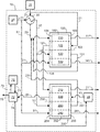
도 1은 다성분 가스 혼합물, 예를 들면 연료 연소기로부터의 연소 가스 흐름으로부터 이산화탄소를 분리하기 위한 본 발명의 일 실시형태에 따른 예시적인 멀티스테이지 가스 흡착 분리 시스템의 간략화된 개략도이다.1 is a simplified schematic diagram of an exemplary multi-stage gas adsorption separation system according to an embodiment of the present invention for separating carbon dioxide from a multicomponent gas mixture, for example, a combustion gas stream from a fuel combustor.
예시적인 멀티스테이지 가스 흡착 분리 시스템은 제 1 스테이지 가스 흡착 분리기 및 제 2 스테이지 가스 흡착 분리기를 사용하며, 여기서 제 1 스테이지 가스 흡착 분리기와 제 2 스테이지 가스 흡착 분리기는 제 1 스테이지 가스 흡착 분리기와 제 2 스테이지 가스 흡착 분리기 사이에서 상이한 재생 매체를 갖는 적어도 하나의 재생 흐름을 이용하고 유입시키기 위해 유체적으로 연결된다. 제 1 스테이지 가스 흡착 분리기는 제 1 재생 매체로서 연소 혼합물을 갖는 제 1 재생 흐름을 유입시키기 위해 유체적으로 연결되고, 제 2 스테이지 가스 흡착 분리기는 제 1 재생 매체로서 증기를 갖는 제 1 재생 흐름을 유입시키기 위해 유체적으로 연결된다.An exemplary multi-stage gas adsorptive separation system employs a first stage gas adsorber separator and a second stage gas adsorber separator wherein the first stage gas adsorber separator and the second stage gas adsorber separator comprise a first stage gas adsorber separator and a second stage gas adsorber separator, And is fluidly connected between the stage gas adsorption separators to utilize and introduce at least one regeneration stream having different regeneration media. The first stage gas adsorption separator is fluidically connected to introduce a first regeneration stream having a combustion mixture as a first regeneration medium and the second stage gas adsorption separator is connected to a first regeneration stream having steam as a first regeneration medium Lt; / RTI >
하나의 실시형태에 따르면, 다성분 유체 혼합물, 예를 들면, 연료 연소기로부터의 연소 가스 흐름으로부터 일 성분(예를 들면, 이산화탄소)의 가스 흡착 분리를 위한 멀티스테이지 가스 흡착 분리 공정(본 명세서에서 "MSA 공정"이라 지칭함)이 제공되며, 일 실시형태의 멀티스테이지 가스 흡착 분리 시스템(이하, "MSA 시스템"이라 지칭함)을 사용한다. 이 실시형태의 MSA 공정은, 공급 흐름이 저압(예를 들면, 약 3 체적%의 저농도 또는 희박 농도의 목표 성분을 포함함)으로 공급되어 압력 변동 흡착 공정을 덜 바람직하게 만들고; 분리될 공급 흐름의 체적이 크고; 예를 들면, 목표 성분의 약 80 체적%를 초과하는 고순도의 생성물 흐름이 요구되고; 목표 성분의 회수량이 높고, 예를 들면, 약 80%를 초과하고; 낮은 에너지 소비가 요구되고; 및/또는 낮은 운전 비용이 요구되는 가스 분리 적용분야에 특히 적합할 수 있다. 예시적인 적용분야에는, 예를 들면, 복합 사이클 발전소의 연소 가스 흐름으로부터 이산화탄소의 연소후 가스 분리가 포함된다.According to one embodiment, a multi-stage gas adsorptive separation process (referred to herein as a " multi-stage gas adsorptive separation process ") for gas sorption separation of a component (e.g., carbon dioxide) from a multicomponent fluid mixture, MSA process ") is provided, and uses a multi-stage gas adsorption separation system (hereinafter referred to as " MSA system ") of one embodiment. The MSA process of this embodiment is advantageous because the feed stream is supplied at a low pressure (including, for example, a target component of a low concentration or lean concentration of about 3% by volume) to make the pressure swing adsorption process less desirable; The volume of the feed stream to be separated is large; For example, a high purity product flow exceeding about 80% by volume of the target component is required; The recovery of the target component is high, e.g., greater than about 80%; Low energy consumption is required; And / or gas separation applications where lower operating costs are required. Exemplary applications include, for example, gas separation of carbon dioxide after combustion from a combustion gas stream of a combined cycle power plant.
본 개시의 하나의 실시형태에 따른 MSA 공정은 복수의 흡착 스테이지를 포함할 수 있고, 여기서 적어도 하나의 흡착 스테이지는 가스 흡착 분리 공정(본 명세서에서 "흡착 공정"이라고 지칭함)을 더 포함하고, 흡착제 물질 상에 흡착된 적어도 하나의 성분의 탈리를 위한 적어도 하나의 재생 단계는 주로 온도 변도, 예를 들면, 흡착 단계와 제 1 재생 단계 중에 적어도 하나의 흡착제 물질의 온도 차이; 분압 변동, 예를 들면, 적어도 하나의 흡착제 물질 상에 흡착된 적어도 하나의 성분의 평형 분압과 제 2 재생 흐름의 적어도 하나의 성분의 분압 또는 농도의 차이; 및/또는 흡착 에너지의 열의 차이, 예를 들면, 적어도 하나의 흡착제 물질 상에 흡착된 적어도 하나의 성분과 제 1 재생 흐름의 적어도 하나의 성분의 흡착 에너지의 열의 차이와 같은 탈리 메커니즘에 의해 구동된다. 예를 들면, 예를 들면, 온도 변동, 분압 변동, 진공, 배기 퍼지 및/또는 퍼지를 포함하는 다른 이차 탈리 메커니즘은 적어도 하나의 흡착제 물질로부터 성분의 탈리를 촉진시킬 수 있다. 예시적인 MSA 공정은 다른 가스 분리 공정, 가스 흡착 분리 공정, 및/또는 탈리 메커니즘, 예를 들면, 압력 변동 가스 흡착 분리 공정 및/또는 진공 변동 가스 흡착 분리 공정을 더 포함하는 흡착 스테이지를 포함할 수 있다. 흡착 공정은 주기적이고, 순차적으로 반복될 수 있다. The MSA process according to one embodiment of the present disclosure may comprise a plurality of adsorption stages, wherein at least one adsorption stage further comprises a gas adsorption separation process (referred to herein as an " adsorption process "), At least one regeneration step for desorption of at least one constituent adsorbed on the material is carried out primarily by temperature variation, for example, the temperature difference of at least one adsorbent material during the adsorption step and the first regeneration step; Partial pressure fluctuations, e. G., The difference in partial pressure or concentration of at least one component of the second regeneration stream, of the at least one component adsorbed on the at least one adsorbent material; And / or by a desorption mechanism, such as a difference in the heat of adsorption energy, for example, the difference in the heat of adsorption energy of at least one component adsorbed on at least one adsorbent material and the at least one component of the first regeneration stream . For example, other secondary desorption mechanisms, including, for example, temperature fluctuations, partial pressure fluctuations, vacuum, exhaust purge, and / or purging, may facilitate desorption of components from at least one adsorbent material. The exemplary MSA process may include an adsorption stage further comprising a further gas separation process, a gas adsorption separation process, and / or a desorption mechanism, for example a pressure variable gas adsorption separation process and / or a vacuum variable gas adsorption separation process have. The adsorption process can be repeated periodically and sequentially.
하나의 실시형태에서, MSA 공정은 MSA 시스템을 사용할 수 있고, 이 시스템은 개별 접촉기를 갖는 복수의 가스 흡착 분리기(본 명세서에서 "흡착 분리기"라고 지칭함) - 여기서 각각의 흡착 분리기 및 접촉기는 MSA 공정의 단일 흡착 스테이지용으로 사용됨 -; 복수의 접촉기를 갖는 단일 흡착 분리기 - 여기서 각각의 접촉기는 MSA 공정의 단일 흡착 스테이지용으로 사용됨 -; 또는 MSA 공정의 단일 흡착 스테이지용으로 사용되는 복수의 접촉기를 갖는 복수의 흡착 분리기를 포함한다. 접촉기는 고정식이거나 가동식, 예를 들면, 회전식일 수 있다.In one embodiment, the MSA process can use an MSA system, which includes a plurality of gas adsorber separators (referred to herein as " adsorber separators ") having individual contactors, wherein each adsorber separator and contactor is connected to an MSA process Used for a single adsorption stage of; A single adsorptive separator having a plurality of contactors, wherein each contactor is used for a single adsorption stage of an MSA process; Or a plurality of adsorber separators having a plurality of contactors used for a single adsorption stage of the MSA process. The contactor may be stationary or movable, for example, rotary.
예시적인 실시형태의 MSA 공정에서, 다성분 유체 혼합물, 예를 들면, 연료 연소기로부터의 연도 가스 흐름 또는 연소 가스 흐름은 적어도 제 1 성분, 예를 들면, 이산화탄소(본 명세서에서 "CO2"로 지칭함) 및 임의선택적으로 제 2 성분, 예를 들면, 질소를 포함할 수 있고, 제 1 성분은 다성분 유체 혼합물로부터 흡착에 의해 분리될 수 있다. 예시적인 MSA 공정 및 시스템은 제 1 흡착 스테이지 또는 제 1 스테이지 흡착 공정 및 제 2 흡착 스테이지 또는 제 2 스테이지 흡착 공정을 포함할 수 있다. 제 1 스테이지 흡착 공정 및 분리기는 유리하게도 제 1 스테이지 흡착 공정 및 분리기의 제 1 재생 단계 중에, 제 1 재생 매체, 예를 들면, 다성분 유체 혼합물, 연소 혼합물, 연도 가스 혼합물, 또는 다성분 유체 혼합물에 비해 제 1 성분으로 부화된 또는 낮은 엑서지(exergy), 저가치 및/또는 저비용을 갖는 유체 혼합물을 포함하는 적어도 제 1 재생 흐름을 사용할 수 있는 다성분 유체 혼합물로부터 제 1 성분의 벌크 가스 분리용으로 사용될 수 있고, 이는 유리하게도 제 1 스테이지 흡착 공정, 제 1 스테이지 흡착 분리기 및 MSA 시스템에서 적어도 하나의 흡착제 물질의 재생을 위한 증기 소비 및/또는 운전 비용을 저감시킬 수 있다. 임의선택적으로, 제 1 스테이지 흡착 공정 및 분리기는 제 1 스테이지 흡착 공정 및 분리기의 임의선택적인 제 2 재생 단계 중에 제 2 재생 매체, 예를 들면, 공기, 다성분 유체 혼합물, 연소 혼합물, 연도 가스 혼합물, 또는 다성분 유체 혼합물에 비해 제 1 성분으로 부화된 유체 혼합물을 포함하는 제 2 재생 흐름을 사용할 수 있다. 제 1 스테이지 흡착 공정 및 분리기의 생성물 흐름, 예를 들면, 다성분 유체 혼합물에 비해 고농도의 제 1 성분을 포함하는 제 2 생성물 흐름 및/또는 제 3 생성물 흐름은 제 1 스테이지 흡착 분리기로부터 회수되어, 제 2 스테이지 흡착 공정 및 분리기를 위한 공급 흐름으로 유입될 수 있고, 이는 유리하게도 제 2 스테이지 흡착 공정에서 가스 흡착 분리 공정의 효율을 상승시킬 수 있다. 제 2 스테이지 흡착 공정 및 분리기는 제 2 스테이지 흡착 공정 및 분리기의 제 1 재생 단계 중에, 제 3 재생 매체, 예를 들면, 증기, 전기, 응축성 가스 또는 용매를 포함하는 적어도 제 1 재생 흐름을 사용할 수 있고, 이는 고농도 또는 고순도의 제 1 성분, 예를 들면, 약 80%를 초과하거나, 또는 구체적으로는 성분의 약 90%를 초과하거나, 또는 더 구체적으로는 약 95 %를 초과하는 제 1 성분을 포함하는 제 2 스테이지 흡착 공정 및 분리기의 제 2 생성물 흐름을 생성할 수 있다. 임의선택적으로, 제 2 스테이지 흡착 공정 및 분리기는 제 2 스테이지 흡착 공정 및 분리기의 임의선택적인 제 2 재생 단계 중에, 임의선택적으로 제 2 재생 매체 또는 제 4 재생 매체, 예를 들면, 공기, 다성분 유체 혼합물, 연소 혼합물, 연도 가스 혼합물, 또는 다성분 유체 혼합물에 비해 제 1 성분으로 부화된 유체 혼합물을 포함하는 제 2 재생 흐름을 사용할 수 있다. 적어도 제 1 스테이지 흡착 공정 및 분리기와 제 2 스테이지 흡착 공정 및 분리기의 새로운 조합은 제 1 스테이지 흡착 공정 및 분리기와 제 2 스테이지 흡착 공정 및 분리기 사이에서 상이한 재생 매체를 갖는 적어도 하나의 재생 흐름을 사용 및 유입시키고, 예를 들면, 제 1 스테이지 흡착 공정 및 분리기는 연소 혼합물을 포함하는 재생 매체를 사용하고, 제 2 스테이지 흡착 공정 및 분리기는 증기를 포함하는 재생 매체를 사용하고, 또는 제 1 스테이지 흡착 공정 및 분리기는 연소 혼합물을 포함하는 제 1 재생 매체 및 공기를 포함하는 제 2 재생 매체를 사용하고, 제 2 스테이지 흡착 공정 및 분리기는 증기를 포함하는 제 1 재생 매체 및 공기를 포함하는 제 2 재생 매체를 사용하고, 상기 조합은 고순도의 생성물 흐름을 제공함과 동시에 유리하게도 가스 흡착 분리 공정의 효율을 향상시키고, 증기 소비, 에너지 소비 및 운전 비용을 저감시킬 수 있다.In an illustrative embodiment of the MSA process, the multicomponent fluid mixture, e.g., flue gas stream or exhaust gas stream from the fuel burner can be, for at least the first component, for example, carbon dioxide (referred to herein as "CO 2" ) And optionally optionally a second component, for example nitrogen, and the first component can be separated from the multicomponent fluid mixture by adsorption. Exemplary MSA processes and systems may include a first adsorption stage or a first stage adsorption process and a second adsorption stage or a second stage adsorption process. The first stage adsorption process and the separator advantageously allow the first stage adsorption process and the first regeneration stage of the separator to produce a first regeneration medium, such as a multicomponent fluid mixture, a combustion mixture, a flue gas mixture, Separation of the first component bulk gas from a multicomponent fluid mixture that is capable of using at least a first regeneration stream enriched with the first component as compared to the first component or comprising a fluid mixture having a low exergy, low value, and / , Which can advantageously reduce steam consumption and / or operating costs for the regeneration of at least one adsorbent material in the first stage adsorption process, the first stage adsorber separator and the MSA system. Optionally, the first stage adsorption process and the separator may comprise a first stage adsorption process and an optional second regeneration stage of the separator during a second regeneration medium, such as air, a multicomponent fluid mixture, a combustion mixture, a flue gas mixture , Or a second regeneration stream comprising a fluid mixture enriched with a first component as compared to a multicomponent fluid mixture. The first stage adsorption process and the product stream of the separator, for example, a second product stream and / or a third product stream comprising a higher concentration of the first component relative to the multicomponent fluid mixture, are withdrawn from the first stage adsorption separator, Can be introduced into the feed stream for the second stage adsorption process and the separator, which can advantageously increase the efficiency of the gas adsorption separation process in the second stage adsorption process. The second stage adsorption process and the separator use at least a first regeneration stream comprising a third regeneration medium, for example steam, electricity, condensable gas or solvent, during the first regeneration step of the second stage adsorption process and the separator , Which may be a first component of high concentration or high purity, for example, greater than about 80%, or specifically greater than about 90%, or more specifically greater than about 95% And a second product stream of the separator. Optionally, the second stage adsorption process and the separator may optionally comprise, during an optional second regeneration step of the second stage adsorption process and separator, a second regeneration medium or a fourth regeneration medium, for example air, A second regeneration stream comprising a fluid mixture, a combustion mixture, a flue gas mixture, or a fluid mixture enriched with a first component as compared to a multicomponent fluid mixture. At least a first stage adsorption process and a new combination of a separator and a second stage adsorption process and a separator may be used in combination with at least one regeneration stream having a different regeneration medium between the first stage adsorption process and the separator and the second stage adsorption process and the separator, For example, the first stage adsorption process and the separator use a regeneration medium comprising a combustion mixture, the second stage adsorption process and the separator use a regeneration medium comprising steam, or the first stage adsorption process And the separator uses a first regeneration medium comprising a combustion mixture and a second regeneration medium comprising air, wherein the second stage adsorption process and the separator use a first regeneration medium comprising steam and a second regeneration medium comprising air, And the combination provides a high purity product stream, while advantageously, Improve the efficiency of the separation process was complex, it is possible to reduce the steam consumption, energy consumption and operating costs.
하나의 실시형태에서, 예시적인 MSA 시스템은 공기 공급원, 열교환기, 제 1 스테이지 흡착 분리기, 제 2 스테이지 흡착 분리기, 증기 공급원, 냉각제 공급원 및 응축기, 예를 들면, 응축 열교환기를 포함한다. 예시적인 제 1 스테이지 흡착 분리기는 임의선택적으로 복수의 영역, 예를 들면, 흡착 영역, 제 1 재생 영역, 제 2 재생 영역, 및 컨디셔닝 영역을 형성할 수 있는 인클로저 내에 수용되는 적어도 하나의 흡착제 물질을 지지하기 위한 접촉기를 포함할 수 있고, 이 접촉기는 복수의 영역을 통해 순환하거나 회전할 수 있고, 축방향으로 대향되는 제 1 단부와 제 2 단부 사이에서 접촉기의 제 1 축선을 따라 배향되는 복수의 실질적으로 평행한 유체 유동 통로, 및 임의선택적으로 접촉기의 벽 내 또는 벽 상의 적어도 하나의 흡착제 물질과 직접 접촉하는 실질적으로 접촉기의 제 1 축선을 따라 배향되는 복수의 축방향으로 연속하는 열전도성 필라멘트를 더 포함한다. 현재 기재된 실시형태 중 임의의 것에서, 제 1 스테이지 흡착 분리기는, 예를 들면, 건조제, 활성탄소, 탄소 흡착제, 흑연, 탄소 분자 체(molecular sieve), 활성화 알루미나, 분자 시브, 알루미노포스페이트, 실리코알루미노포스페이트, 제올라이트 흡착제, 이온 교환 제올라이트, 친수성 제올라이트, 소수성 제올라이트, 개질 제올라이트, 천연 제올라이트, 파우자사이트(faujasite), 클리노프틸로라이트(clinoptilolite), 모데나이트, 금속 교환 실리코-알루미노포스페이트, 단극성 수지, 이극성 수지, 방향족 가교성 폴리스티렌계 매트릭스, 브롬계 방향족 매트릭스, 메타크릴 에스터 코폴리머, 흑연 흡착제, 탄소 섬유, 탄소 나노튜브, 나노 물질, 금속염 흡착제, 과염소산염, 옥살산염, 알칼리 토금속 입자, ETS, CTS, 금속 산화물, 담지 알칼리 카보네이트, 알칼리-촉진 하이드로탈사이트, 화학흡착제, 아민, 유기-금속 반응제, 및 금속 유기 프레임워크 흡착제 물질, 및 이들의 조합을 포함하는 임의의 적합한 흡착제 물질을 사용할 수 있으나, 이들에 한정되지 않는다. 예시적인 제 2 스테이지 흡착 분리기는 예시적인 제 1 스테이지 흡착 분리기와 실질적으로 유사할 수 있으나, 반드시 그럴 필요는 없고, 예를 들면, 제 2 스테이지 흡착 분리기는 제 1 스테이지 흡착 분리기과 상이한 적어도 하나의 흡착제 물질, 복수의 영역 및/또는 접촉기 구성을 포함할 수 있다.In one embodiment, an exemplary MSA system includes an air source, a heat exchanger, a first stage adsorber separator, a second stage adsorber separator, a vapor source, a coolant source and a condenser, for example, a condensing heat exchanger. An exemplary first stage adsorptive separator may optionally include at least one adsorbent material contained within an enclosure capable of forming a plurality of zones, for example, an adsorption zone, a first regeneration zone, a second regeneration zone, and a conditioning zone The contactor being rotatable or rotatable through a plurality of regions and having a plurality of axially oriented first and second axially aligned contactors between the first and second axially opposing ends, A plurality of axially contiguous thermally conductive filaments oriented substantially along a first axis of the contactor in direct contact with at least one adsorbent material in or on the wall of the contactor, . In any of the presently described embodiments, the first stage adsorptive separator may be a desiccant, for example, a desiccant, an activated carbon, a carbon adsorbent, graphite, a molecular sieve, activated alumina, a molecular sieve, an aluminophosphate, A zeolite adsorbent, an ion exchange zeolite, a hydrophilic zeolite, a hydrophobic zeolite, a modified zeolite, a natural zeolite, a faujasite, a clinoptilolite, a mordenite, a metal exchanged silico-aluminophosphate, The present invention relates to a method for producing a polyolefin resin, which comprises the steps of mixing a polar resin, a polar resin, an aromatic crosslinking polystyrene matrix, a brominated aromatic matrix, a methacrylic ester copolymer, a graphite adsorbent, a carbon fiber, a carbon nanotube, a nanomaterial, a metal salt adsorbent, , ETS, CTS, metal oxides, supported alkaline carbonates, alkali-promoted But are not limited to, any suitable adsorbent material, including, for example, hydrotalcite, idotolite, chemisorbents, amines, organo-metal reactants, and metal organic framework adsorbent materials, and combinations thereof. An exemplary second stage adsorber separator may be substantially similar to, but need not be, substantially similar to the exemplary first stage adsorber separator, for example, the second stage adsorber separator may comprise at least one adsorbent material different than the first stage adsorber separator , A plurality of regions, and / or a contactor configuration.
추가의 실시형태에서, 다성분 유체 혼합물로부터 적어도 제 1 성분을 분리하기 위한 예시적인 멀티스테이지 가스 흡착 분리 공정은 다음의 단계를 포함할 수 있다.In a further embodiment, an exemplary multi-stage gas adsorption separation process for separating at least a first component from a multicomponent fluid mixture may comprise the following steps.
a. 다성분 유체 흐름, 예를 들면, 연소 가스 흐름을 공급 흐름의 적어도 일부로서 그리고 임의선택적으로 제 1 스테이지 가스 흡착 분리기의 제 1 재생 흐름으로서 멀티스테이지 가스 흡착 분리 시스템 내에 유입시키는 단계;a. Introducing a multicomponent fluid stream, e.g., a combustion gas stream, into at least a portion of the feed stream and optionally as a first regeneration stream of the first stage gas adsorptive separator into the multi-stage gas adsorptive separation system;
b. 임의선택적으로, 열교환기의 고온 회로 내에 제 1 스테이지 가스 흡착 분리기를 위한 공급 흐름의 적어도 일부로서 다성분 유체 흐름의 적어도 일부를 유입시키는 단계, 제 1 임계 온도 이하의 온도까지 제 1 스테이지 가스 흡착 분리기를 위한 공급 흐름의 적어도 일부의 온도를 저하시키는 단계, 열교환기의 고온 회로로부터 제 1 스테이지 가스 흡착 분리기를 위한 공급 흐름의 적어도 일부를 회수하는 단계;b. Optionally introducing at least a portion of the multicomponent fluid flow as at least a portion of the feed stream for the first stage gas adsorptive separator in the high temperature circuit of the heat exchanger, to a temperature below the first critical temperature, Withdrawing at least a portion of the feed stream for the first stage gas adsorption separator from the high temperature circuit of the heat exchanger;
c. 제 1 스테이지 가스 흡착 분리기 내에, 그리고 제 1 스테이지 가스 흡착 분리기 내의 접촉기의 제 1 단부 내에 제 1 스테이지 가스 흡착 분리기를 위한 공급 흐름의 적어도 일부를 제 1 임계 온도 이하의 온도로 유입시키는 단계; 제 1 스테이지 가스 흡착 분리기 내의 접촉기 내의 적어도 하나의 흡착제 물질 상에 제 1 스테이지 가스 흡착 분리기의 공급 흐름의 제 1 성분의 적어도 일부를 흡착시키는 단계; 제 2 임계 온도까기 제 1 스테이지 가스 흡착 분리기 내의 접촉기 내의 적어도 하나의 흡착제 물질의 온도를 승온시키는 단계; 제 1 스테이지 가스 흡착 분리기 내의 접촉기의 제 2 단부, 제 1 스테이지 가스 흡착 분리기 및 멀티스테이지 가스 흡착 분리 시스템으로부터 (다성분 유체 혼합물 및/또는 제 1 스테이지 가스 흡착 분리기를 위한 공급 흐름에 비해 제 1 성분이 적어도 주기적으로 고갈되는) 제 1 스테이지 가스 흡착 분리기의 제 1 생성물 흐름을 회수하는 단계;c. Introducing at least a portion of the feed stream for the first stage gas adsorber separator into the first stage gas adsorber separator and into the first end of the contactor within the first stage gas adsorber separator at a temperature below the first critical temperature; Adsorbing at least a portion of the first component of the feed stream of the first stage gas adsorber separator onto at least one adsorbent material in the contactor in the first stage gas adsorber separator; Raising the temperature of the at least one adsorbent material in the contactor within the first stage gas adsorptive separator to a second threshold temperature; The first stage gas adsorption separator and the multi-stage gas adsorptive separation system (the first stage gas adsorbing separator and / or the first stage gas adsorbing separator), from the second end of the contactor in the first stage gas adsorber separator, Recovering a first product stream of a first stage gas adsorber separator that is at least periodically depleted;
d.
제 1 스테이지 가스 흡착 분리기 내에, 그리고 임의선택적으로 제 1 스테이지 가스 흡착 분리기 내의 접촉기의 제 2 단부 내에 제 1 재생 매체, 예를 들면, 다성분 유체 혼합물 또는 연소 혼합물을 갖는 제 1 스테이지 가스 흡착 분리기를 위한 제 1 재생 흐름을 유입시키는 단계; 단계 c에서 달성되는 제 2 임계 온도로부터 제 3 임계 온도까지 제 1 스테이지 가스 흡착 분리기 내의 접촉기 내의 적어도 하나의 흡착제 물질의 온도를 승온시키는 단계; 제 1 스테이지 가스 흡착 분리기 내의 접촉기 내의 적어도 하나의 흡착제 물질 상에 흡착된 제 1 성분의 적어도 일부를 탈리시키는 단계; 다성분 유체 혼합물 및/또는 임의선택적으로 제 1 스테이지 가스 흡착 분리기 내의 접촉기의 제 1 단부(104) 및 제 1 스테이지 가스 흡착 분리기으로부터의 제 1 스테이지 가스 흡착 분리기을 위한 공급 흐름에 비해 제 1 성분으로 부화된 제 1 스테이지 가스 흡착 분리기의 제 2 생성물 흐름을 회수하는 단계;d.
A first stage gas adsorption separator having a first regeneration medium, for example a multicomponent fluid mixture or combustion mixture, in a first stage gas adsorber separator and optionally in a second end of a contactor in a first stage gas adsorber separator, Introducing a first regeneration stream for the first regeneration stream; Raising the temperature of the at least one adsorbent material in the contactor in the first stage gas adsorber separator from a second threshold temperature achieved in step c to a third threshold temperature; Desorbing at least a portion of the first component adsorbed on at least one adsorbent material in the contactor in the first stage gas adsorptive separator; As compared to the feed stream for the first stage gas adsorption separator from the
e. 제 1 스테이지 가스 흡착 분리기 및 제 2 스테이지 가스 흡착 분리기를 위한 제 2 재생 흐름, 및 임의선택적으로 단일 공급원 또는 공통 공급원, 예를 들면, 주위 공기 공급원, 팬, 또는 불활성 가스 공급원으로부터 제 1 스테이지 가스 흡착 분리기 및 제 2 스테이지 가스 흡착 분리기를 위한 컨디셔닝 흐름, 예를 들면, 공기 흐름 또는 실질적으로 제 2 성분을 포함하는 유체 흐름을 공급하는 단계;e. A first stage gas adsorption separator and a second regeneration stream for a second stage gas adsorber separator and optionally a first stage gas adsorption from a single source or common source such as an ambient air source, Supplying a fluid stream comprising a conditioning stream for the separator and the second stage gas adsorptive separator, for example, an air stream or a substantially second component;
f. 임의선택적으로 열교환기의 저온 회로 내에 제 2 재생 흐름을 유입시키는 단계; 제 4 임계 온도까지 제 2 재생 흐름의 온도를 승온시키는 단계; 열교환기의 저온 회로로부터 제 2 재생 흐름을 회수하는 단계;f. Optionally introducing a second regeneration stream into the low temperature circuit of the heat exchanger; Raising the temperature of the second regeneration stream to a fourth critical temperature; Recovering a second regeneration stream from the low temperature circuit of the heat exchanger;
g. 제 1 스테이지 가스 흡착 분리기 내에, 그리고 임의선택적으로 제 1 스테이지 가스 흡착 분리기 내의 접촉기의 제 1 단부 내에, 제 4 임계 온도로, 제 2 재생 매체, 예를 들면, 공기를 갖는 제 1 스테이지 가스 흡착 분리기를 위한 제 2 재생 흐름을 유입시키는 단계; 제 1 스테이지 가스 흡착 분리기 내의 접촉기 내의 적어도 하나의 흡착제 물질 상에 흡착된 제 1 성분의 적어도 일부를 탈리시키는 단계; 제 5 임계 온도까지 제 1 스테이지 가스 흡착 분리기 내의 접촉기 내의 적어도 하나의 흡착제 물질의 온도를 저하시키는 단계; 다성분 유체 혼합물 및/또는 임의선택적으로 제 1 스테이지 가스 흡착 분리기 내의 접촉기의 제 2 단부 및 제 1 스테이지 가스 흡착 분리기로부터 제 1 스테이지 가스 흡착 분리기를 위한 공급 흐름에 비해 제 1 성분으로 부화된 제 1 스테이지 가스 흡착 분리기의 제 3 생성물 흐름을 회수하는 단계; 제 1 스테이지 가스 흡착 분리기 내에 그리고 제 1 스테이지 가스 흡착 분리기 내의 접촉기의 제 1 단부 내에 제 1 스테이지 가스 흡착 분리기을 위한 공급 흐름의 일부로서 제 1 스테이지 가스 흡착 분리기의 제 3 생성물 흐름을 유입시키고, 임의선택적으로 조합하는 단계;g. Stage gas adsorption separator with a second regeneration medium, e.g., air, at a fourth critical temperature, within the first stage gas adsorber separator, and optionally optionally, within the first end of the contactor within the first stage gas adsorption separator Introducing a second regeneration stream for the first regeneration stream; Desorbing at least a portion of the first component adsorbed on at least one adsorbent material in the contactor in the first stage gas adsorptive separator; Lowering the temperature of the at least one adsorbent material in the contactor in the first stage gas adsorber separator to a fifth threshold temperature; Component fluid mixture and / or optionally a second stage of contactor in the first stage gas-adsorber separator and a first stage gas-adsorbing separator, the first stage gas- Recovering a third product stream of the stage gas adsorptive separator; Introducing the third product stream of the first stage gas adsorption separator as part of the feed stream for the first stage gas adsorption separator within the first stage gas adsorber separator and into the first end of the contactor within the first stage gas adsorber separator, ;
h. 제 1 스테이지 가스 흡착 분리기 및 임의선택적으로 제 1 스테이지 가스 흡착 분리기 내의 접촉기의 제 1 단부 내에 제 1 스테이지 가스 흡착 분리기를 위한 컨디셔닝 흐름을 임의선택적으로 유입시키는 단계; 제 6 임계 온도까지 제 1 스테이지 가스 흡착 분리기 내의 접촉기 내의 적어도 하나의 흡착제 물질의 온도를 저하시키는 단계; 임의선택적으로 제 1 스테이지 가스 흡착 분리기 내의 접촉기의 제 2 단부, 제 1 스테이지 가스 흡착 분리기, 및 멀티스테이지 가스 흡착 분리 시스템으로부터 제 1 스테이지 가스 흡착 분리기의 제 4 생성물 흐름을 회수하는 단계;h. Optionally selectively introducing a conditioning stream for a first stage gas adsorber separator and optionally a first stage gas adsorber separator within a first end of a contactor within the first stage gas adsorber separator; Lowering the temperature of the at least one adsorbent material in the contactor in the first stage gas adsorptive separator to a sixth critical temperature; Recovering a fourth product stream of a first stage gas adsorption separator from a second end of the contactor optionally in a first stage gas adsorber separator, a first stage gas adsorber separator, and a multi-stage gas adsorptive separation system;
i. 제 2 스테이지 가스 흡착 분리기 내에 그리고 제 2 스테이지 가스 흡착 분리기의 접촉기의 제 1 단부 내에 제 2 스테이지 가스 흡착 분리기을 위한 공급 흐름의 적어도 일부로서 제 1 스테이지 가스 흡착 분리기의 제 2 생성물 흐름의 적어도 일부를 유입시키는 단계; 제 2 스테이지 가스 흡착 분리기 내의 접촉기 내의 적어도 하나의 흡착제 물질 상에 다성분 유체 혼합물의 제 1 성분 또는 제 2 성분 및/또는 제 2 스테이지 가스 흡착 분리기를 위한 공급 흐름을 흡착시키는 단계; 제 7 임계 온도까지 제 2 스테이지 가스 흡착 분리기 내의 접촉기 내의 적어도 하나의 흡착제 물질의 온도를 승온시키는 단계; 제 2 스테이지 가스 흡착 분리기 내의 접촉기의 제 2 단부, 제 2 스테이지 가스 흡착 분리기 및 멀티스테이지 가스 흡착 분리 시스템으로부터 (다성분 유체 혼합물 및/또는 제 2 스테이지 가스 흡착 분리기을 위한 공급 흐름에 비해 제 1 성분 또는 제 2 성분 중 적어도 하나가 적어도 주기적으로 고갈되는) 제 2 스테이지 가스 흡착 분리기의 제 1 생성물 흐름을 회수하는 단계;i. At least a portion of the second product gas stream of the first stage gas adsorption separator is introduced into the second stage gas adsorber separator and into at least a portion of the feed stream for the second stage gas sorbent separator within the first end of the contactor of the second stage gas sorbent separator ; Adsorbing a feed stream for a first component or a second component of a multicomponent fluid mixture and / or a second stage gas adsorption separator on at least one adsorbent material in a contactor in a second stage gas adsorber separator; Heating the temperature of the at least one adsorbent material in the contactor in the second stage gas adsorptive separator to a seventh critical temperature; Stage gas adsorption separator system and the second stage gas adsorption separator system in the second stage gas adsorber separator (as compared to the feed stream for the multicomponent fluid mixture and / or the second stage gas adsorption separator, Recovering a first product stream of a second stage gas adsorber separator wherein at least one of the second components is at least periodically depleted;
j. 제 2 스테이지 가스 흡착 분리기를 위한 제 1 재생 흐름, 예를 들면, 증기 흐름을 공급하는 단계; 제 2 스테이지 가스 흡착 분리기 내에, 그리고 임의선택적으로 제 2 스테이지 가스 흡착 분리기 내의 접촉기의 제 2 단부 내에 제 3 재생 매체, 예를 들면, 물을 갖는 제 2 스테이지 가스 흡착 분리기를 위한 제 1 재생 흐름을 유입시키는 단계; 제 8 임계 온도까지 제 2 스테이지 가스 흡착 분리기 내의 접촉기 내의 적어도 하나의 흡착제 물질의 온도를 승온시키는 단계; 제 2 스테이지 가스 흡착 분리기 내의 접촉기 내의 적어도 하나의 흡착제 물질 상의 제 1 성분 또는 제 2 성분 중 하나의 적어도 일부를 탈리시키는 단계; 임의선택적으로 다성분 유체 혼합물 및/또는 제 2 스테이지 가스 흡착 분리기 내의 접촉기의 제 1 단부 및 제 2 스테이지 가스 흡착 분리기로부터 제 2 스테이지 가스 흡착 분리기의 공급 흐름에 비해 제 1 성분 또는 제 2 성분이 고갈된 제 2 스테이지 가스 흡착 분리기의 제 2 생성물 흐름을 회수하는 단계;j. Supplying a first regeneration stream, e.g., a vapor stream, for the second stage gas adsorber separator; A first regeneration stream for a second stage gas adsorption separator, and optionally a second regeneration gas, for example a water, with a third regeneration medium in the second end of the contactor in the second stage gas adsorption separator, ; Raising the temperature of the at least one adsorbent material in the contactor in the second stage gas adsorber separator to an eighth critical temperature; Desorbing at least a portion of one of the first component or the second component on the at least one adsorbent material in the contactor in the second stage gas adsorptive separator; The first component or the second component may be depleted relative to the feed stream of the second stage gas adsorption separator from the first end of the contactor and / or from the second stage gas adsorption separator optionally in the multicomponent fluid mixture and / or the second stage gas adsorber separator Recovering a second product stream of the second stage gas adsorber separator;
k. 응축 열교환기 내에 제 2 스테이지 가스 흡착 분리기의 제 2 생성물 흐름을 유입시키는 단계; 제 2 스테이지 가스 흡착 분리기의 제 2 생성물 흐름의 온도를 저하시켜 고순도의 제 2 생성물 흐름 및 응축물 흐름을 형성하는 단계; 응축 열교환기 및 멀티스테이지 가스 흡착 분리 시스템으로부터 고순도의 제 2 생성물 흐름을 회수하는 단계; 축 열교환기 및 멀티스테이지 가스 흡착 분리 시스템으로부터 응축물 흐름을 회수하는 단계;k. Introducing a second product stream of a second stage gas adsorbing separator into the condensing heat exchanger; Lowering the temperature of the second product stream of the second stage gas adsorptive separator to form a high purity second product stream and a condensate stream; Recovering a high purity second product stream from the condensing heat exchanger and the multi-stage gas adsorption separation system; Recovering the condensate stream from the shaft heat exchanger and the multi-stage gas adsorption separation system;
l. 제 2 스테이지 가스 흡착 분리기 내에, 그리고 임의선택적으로 제 2 스테이지 가스 흡착 분리기 내의 접촉기의 제 1 단부 내에, 제 9 임계 온도로, 제 2 재생 매체를 갖는 제 2 스테이지 가스 흡착 분리기를 위한 제 2 재생 흐름을 유입시키는 단계; 제 2 스테이지 가스 흡착 분리기 내의 접촉기 내의 적어도 하나의 흡착제 물질 상에 흡착된 제 1 성분 또는 제 2 성분 중 하나의 적어도 일부를 탈리시키는 단계; 제 10 임계 온도까지 제 2 스테이지 가스 흡착 분리기 내의 접촉기 내의 적어도 하나의 흡착제 물질의 온도를 저하시키는 단계; 다성분 유체 혼합물 및/또는 임의선택적으로 제 2 스테이지 가스 흡착 분리기 내의 접촉기의 제 2 단부 및 임의선택적으로 제 2 스테이지 가스 흡착 분리기로부터 제 2 스테이지 가스 흡착 분리기의 공급 흐름에 비해 제 1 성분 및 제 2 성분으로 부화된 제 2 스테이지 가스 흡착 분리기의 제 3 생성물 흐름을 회수하는 단계; 제 1 스테이지 가스 흡착 분리기 내에 그리고 제 1 스테이지 가스 흡착 분리기 내의 접촉기의 제 1 단부 내에 제 1 스테이지 가스 흡착 분리기를 위한 공급 흐름의 일부로서 제 2 스테이지 가스 흡착 분리기의 제 3 생성물 흐름을 유입시키는 단계;l. Within the second stage gas adsorber separator and optionally also in the first end of the contactor in the second stage gas adsorption separator, at a ninth critical temperature, a second regeneration stream for a second stage gas adsorber separator having a second regeneration medium ; Desorbing at least a portion of one of the first component or the second component adsorbed on the at least one adsorbent material in the contactor in the second stage gas adsorptive separator; Lowering the temperature of the at least one adsorbent material in the contactor in the second stage gas adsorber separator to a 10th critical temperature; Stage gas adsorption separator as compared to the feed stream of the second stage gas adsorption separator from the second end of the contactor in the multicomponent fluid mixture and / or optionally optionally the second stage gas adsorber separator and optionally also from the second stage gas adsorber separator, Recovering a third product stream of the second stage gas adsorbing separator enriched with the components; Introducing a third product stream of the second stage gas adsorption separator as part of a feed stream for the first stage gas adsorption separator within the first stage gas adsorber separator and into the first end of the contactor within the first stage gas adsorber separator;
m. 제 2 스테이지 가스 흡착 분리기 및 제 2 스테이지 가스 흡착 분리기 내의 접촉기의 제 1 단부 내에 제 2 스테이지 가스 흡착 분리기를 위한 컨디셔닝 흐름을 유입시키는 단계; 제 11 임계 온도까지 제 2 스테이지 가스 흡착 분리기 내의 접촉기 내의 적어도 하나의 흡착제 물질의 온도를 저하시키는 단계; 제 2 스테이지 가스 흡착 분리기 내의 접촉기의 제 2 단부, 제 2 스테이지 가스 흡착 분리기, 및 멀티스테이지 가스 흡착 분리 시스템으로부터 제 2 스테이지 가스 흡착 분리기의 제 4 생성물 흐름을 회수하는 단계.m. Introducing a conditioning stream for a second stage gas adsorption separator within a first end of a contactor in a second stage gas adsorber separator and a second stage gas adsorber separator; Lowering the temperature of the at least one adsorbent material in the contactor in the second stage gas adsorber separator to an eleventh critical temperature; Withdrawing the fourth product stream of the second stage gas adsorption separator from the second end of the contactor, the second stage gas adsorption separator, and the multi-stage gas adsorption separation system in the second stage gas adsorption separator.
예시적인 MSA 공정의 이러한 하나의 실시형태에서, 제 1 임계 온도는, 예를 들면, 약 50℃, 또는 구체적으로는 약 40℃, 또는 더 구체적으로는 약 30℃일 수 있고; 제 2 임계 온도는 제 1 임계 온도보다 높을 수 있고; 제 3 임계 온도는 제 2 임계 온도보다 높을 수 있고; 제 4 임계 온도는 제 3 임계 온도 이하, 그리고 제 2 임계 온도 이상일 수 있고; 제 5 임계 온도는 제 2 임계 온도 이상일 수 있고; 제 6 임계 온도는 제 2 임계 온도 이하일 수 있고; 제 7 임계 온도는 제 2 임계 온도보다 높을 수 있고; 제 8 임계 온도는 제 7 임계 온도보다 높을 수 있고; 제 9 임계 온도는 제 8 임계 온도 이하일 수 있고; 제 10 임계 온도는 제 9 임계 온도 이하일 수 있고; 제 11 임계 온도는 제 10 임계 온도 및 제 6 임계 온도 이하일 수 있고; 제 2 임계 온도와 제 3 임계 온도 사이의 온도 변화는 제 7 임계 온도와 제 8 임계 온도 사이의 온도 변화 이상일 수 있다.In this one embodiment of the exemplary MSA process, the first critical temperature may be, for example, about 50 캜, or specifically about 40 캜, or, more specifically, about 30 캜; The second threshold temperature may be higher than the first threshold temperature; The third threshold temperature may be higher than the second threshold temperature; The fourth critical temperature may be below a third critical temperature, and above a second critical temperature; The fifth threshold temperature may be greater than or equal to the second threshold temperature; The sixth critical temperature may be below a second critical temperature; The seventh critical temperature may be higher than the second critical temperature; The eighth critical temperature may be higher than the seventh critical temperature; The ninth threshold temperature may be below the eighth threshold temperature; The tenth threshold temperature may be below the ninth threshold temperature; The eleventh critical temperature may be lower than or equal to the tenth critical temperature and the sixth critical temperature; The temperature change between the second critical temperature and the third critical temperature may be equal to or more than the temperature change between the seventh critical temperature and the eighth critical temperature.
추가의 실시형태의 예시적인 MSA 공정에서, 다성분 유체 혼합물은 연소 가스 혼합물, 연도 가스 혼합물, 다른 가스 분리 공정으로부터의 생성물 흐름 또는 천연 가스를 더 포함할 수 있고; 제 1 성분은 이산화탄소, 산소, 또는, 예를 들면, 황 산화물, 질소 산화물, 미립자 물질 및 중금속(예를 들면, 수은 및 베릴륨)을 포함하는 오염물 중 임의의 하나일 수 있고, 제 2 성분은 질소, 이산화탄소, 산소, 또는, 예를 들면, 황 산화물, 질소 산화물, 미립자 물질 및 중금속(예를 들면, 수은 및 베릴륨)을 포함하는 오염물 중 임의의 하나일 수 있고; 제 1 재생 흐름 및/또는 제 2 재생 흐름은 임의선택적으로 엑서지가 낮을 수 있고 및/또는 MSA 공정이 통합된 일 공정의 배출 유체 흐름 또는 배기 유체 흐름의 적어도 일부로서 임의선택적으로 회수될 수 있고, 제 1 재생 매체는 다른 가스 분리 공정 및/또는 분리기로부터의 생성물 혼합물, 응축성 가스 또는 용매, 공기, 이산화탄소, 증기 형태의 물 또는 전기를 더 포함할 수 있고; 제 2 재생 매체는 다성분 유체 혼합물, 연소 가스 혼합물, 연도 가스 혼합물, 공기, 불활성 가스, 이산화탄소, 다른 가스 분리 공정 및/또는 장치로부터의 생성물 혼합물, 응축성 가스, 증기 형태의 물 또는 전기를 더 포함할 수 있고; 제 3 재생 매체는 공기, 불활성 가스 또는 이산화탄소를 더 포함할 수 있다.In an exemplary MSA process of a further embodiment, the multicomponent fluid mixture may further comprise a combustion gas mixture, a flue gas mixture, a product stream from another gas separation process, or a natural gas; The first component may be any one of carbon dioxide, oxygen, or contaminants including, for example, sulfur oxides, nitrogen oxides, particulate materials and heavy metals (e.g., mercury and beryllium) , Carbon dioxide, oxygen, or contaminants including, for example, sulfur oxides, nitrogen oxides, particulate materials, and heavy metals (e.g., mercury and beryllium); The first regeneration stream and / or the second regeneration stream may optionally be exothermically lowered and / or the MSA process may optionally be recovered as at least a portion of an integrated process exhaust stream or exhaust stream, The first regeneration medium may further comprise a product mixture from another gas separation process and / or a separator, a condensable gas or solvent, air, carbon dioxide, water in the form of steam or electricity; The second regeneration medium may further comprise a product mixture from a multicomponent fluid mixture, a combustion gas mixture, a flue gas mixture, air, inert gas, carbon dioxide, other gas separation processes and / or devices, condensable gas, ; The third regeneration medium may further comprise air, an inert gas or carbon dioxide.
이러한 하나의 실시형태에서, 예시적인 MSA 공정의 단계 c는 제 1 스테이지 흡착 공정의 흡착 단계를 나타낼 수 있고; 단계 d는 제 1 스테이지 흡착 공정의 제 1 재생 단계를 나타낼 수 있고; 단계 g는 제 1 스테이지 흡착 공정의 임의선택적인 제 2 재생 단계를 나타낼 수 있고; 단계 h는 제 1 스테이지 흡착 공정의 임의선택적인 컨디셔닝 단계를 나타낼 수 있고; 단계 i는 제 2 스테이지 흡착 공정의 흡착 단계를 나타낼 수 있고; 단계 j 및 임의선택적으로 단계 k는 제 2 스테이지 흡착 공정의 제 1 재생 단계를 나타낼 수 있고; 단계 l은 제 2 스테이지 흡착 공정의 임의선택적인 제 2 재생 단계를 나타낼 수 있고; 단계 m은 제 2 스테이지 흡착 공정의 임의선택적인 컨디셔닝 단계를 나타낼 수 있고; 단계 a 내지 단계 m은 MSA 공정 및 MSA 시스템에서 실질적으로 동시에 발생될 수 있고; 단계 c, d, g, h, i., j, l, 및 m은 MSA 공정 및 MSA 시스템에서 실질적으로 동시에 발생될 수 있고; 단계 c, d, i, 및 j는 MSA 공정 및 MSA 시스템에서 실질적으로 동시에 발생될 수 있고; 단계 c, d, g, 및 h는 흡착 공정 및 분리기의 임의의 스테이지에서 순차적으로 그리고 주기적으로 반복되어 발생될 수 있고, 단계 i, j, l, 및 m은 흡착 공정 및 분리기의 임의의 스테이지에서 순차적으로 그리고 주기적으로 반복되어 발생될 수 있다.In one such embodiment, step c of the exemplary MSA process may represent the adsorption step of the first stage adsorption process; Step d may represent a first regeneration step of the first stage adsorption process; Step g may represent an optional second regeneration step of the first stage adsorption process; Step h may represent any optional conditioning step of the first stage adsorption process; Step i may represent the adsorption step of the second stage adsorption process; Step j and optionally optionally step k may represent a first regeneration step of the second stage adsorption process; Step 1 may represent an optional second regeneration step of the second stage adsorption process; Step m may represent any optional conditioning step of the second stage adsorption process; Steps a to m can occur substantially simultaneously in the MSA process and the MSA system; Steps c, d, g, h, i., J, l, and m can occur substantially simultaneously in the MSA process and the MSA system; Steps c, d, i, and j can occur substantially simultaneously in the MSA process and the MSA system; Steps c, d, g, and h may be repeated sequentially and periodically at any stage of the adsorption process and separator, steps i, j, l, and m may occur at any stage of the adsorption process and separator It can be generated repeatedly in sequence and periodically.
대안적 실시형태에서, 예시적인 MSA 공정에서, 복수의 흡착 스테이지, 예를 들면, MSA 공정의 단계 b 내지 h 및/또는 단계 i 내지 m이 사용될 수 있고; 흡착 스테이지는 흡착 단계 및 재생 단계, 예를 들면, 단계 b 및 c 또는 단계 i 및 j를 포함할 수 있고; 제 1 흡착 스테이지 또는 제 1 스테이지 가스 흡착 분리기 내에 유입된 제 2 재생 흐름은 제 2 흡착 스테이지 또는 제 2 스테이지 가스 흡착 분리기 내에 유입된 제 2 재생 흐름과 상이한 매체일 수 있고; 제 1 흡착 스테이지 또는 제 1 스테이지 가스 흡착 분리기 및 제 2 흡착 스테이지 또는 제 2 스테이지 가스 흡착 분리기 내에 유입된 제 1 재생 흐름은 동일 재생 매체를 더 포함할 수 있고, 제 1 흡착 스테이지 또는 제 1 스테이지 가스 흡착 분리기 및 제 2 흡착 스테이지 또는 제 2 스테이지 가스 흡착 분리기 내에 유입된 제 2 재생 흐름은 상이한 재생 매체를 더 포함할 수 있고; 유체 흐름, 예를 들면, 공급 흐름, 제 1 재생 흐름, 제 2 재생 흐름, 컨디셔닝 흐름은 가스 흡착 분리기 내의 일 영역, 예를 들면, 흡착 영역, 제 1 재생 영역, 제 2 재생 영역, 컨디셔닝 영역 내로 유입된 후에 유체 흐름을 가스 흡착 분리기 내의 접촉기 내로 유입시키고; MSA 공정의 흡착 스테이지는, 예를 들면, 일 실시형태의 MSA 공정 및 시스템 내의 다성분 혼합물로부터 상이한 성분의 가스 흡착 분리를 제공할 수 있고, 제 1 스테이지 흡착 공정 및 분리기는 다성분 혼합물로부터 오염물, 예를 들면, 황 산화물, 질소 산화물, 미립자 물질 및 중금속(예를 들면, 수은 및 베릴륨)의 가스 흡착 분리를 제공할 수 있고, 적어도 제 2 스테이지 흡착 공정 및 분리기는 다성분 혼합물로부터 CO2, 산소, 질소 또는 오염물의 가스 흡착 분리를 제공할 수 있다. 주기적으로, 예를 들면, 사전결정된 임계값, 예를 들면, 접촉기의 제 2 단부로부터 제 1 생성물 흐름의 누출, 접촉기의 제 2 단부 또는 그 부근의, 또는 사전결정된 시간에서의 사전결정된 온도가 달성된 경우, 제 1 성분으로 부분적으로 부화될 수 있는 제 1 생성물 흐름의 일부가 유리하게도 공급 흐름으로부터 제 1 성분의 회수를 증가시킬 수 있는 흡착 단계를 위한 공급 흐름의 일부로서 흡착 분리기 및 적어도 하나의 접촉기의 제 1 단부 내로 임의선택적으로 재순환 및 유입될 수 있고, 예를 들면, 제 1 스테이지 흡착 분리기로부터의 제 1 생성물 흐름은 제 1 스테이지 가스 흡착 분리기 내로 공급 흐름의 일부로서 재순환 및 유입될 수 있고, 제 2 스테이지 흡착 분리기로부터의 제 1 생성물 흐름은 제 1 스테이지 및/또는 제 2 스테이지 가스 흡착 분리기 내로 공급 흐름의 일부로서 재순환 및 유입될 수 있다. 임의선택적으로, 제 2 생성물 흐름은 제 2 스테이지 가스 흡착 분리기로부터 회수되어, 응축 열교환기, 펌프, 예를 들면, 이젝터, 진공 펌프, 또는 주위 압력 미만의 입구 압력으로 작동하는 단일 스테이지 또는 멀티스테이지 압축기 및 임의선택적인 밸브, 예를 들면, 체크 밸브 내에 유입될 수 있고, 여기서 펌프는 응축 열교환기 내의 압력을 감소시키고, 감소된 이 압력을 유지하는 것을 도와줄 수 있다. 임의선택적으로, 제 2 생성물 흐름은 제 2 스테이지 가스 흡착 분리기로부터 회수되어, 유체적으로 직렬 연결된 복수의 응축 열교환기 및 펌프 내에 유입될 수 있다. 임의선택적으로, 흡착 공정 및 분리기 내에 유입되는 고온의 공급 흐름에 적합한 흡착제, 예를 들면, 담지 알칼리 카보네이트 및 알칼리 촉진형 하이드로탈사이트를 사용하는 흡착 공정 및 분리기는 약 200℃의 제 1 임계 온도 이하의 온도에 있을 수 있다.In an alternative embodiment, in an exemplary MSA process, a plurality of adsorption stages may be used, for example, steps b to h and / or steps i to m of the MSA process; The adsorption stage may comprise an adsorption step and a regeneration step, for example steps b and c or steps i and j; The second regeneration stream introduced into the first adsorption stage or the first stage gas adsorption separator may be a different medium than the second regeneration stream introduced into the second adsorption stage or the second stage gas adsorption separator; The first regeneration stream introduced into the first adsorption stage or the first stage gas adsorption separator and the second adsorption stage or the second stage gas adsorption separator may further comprise the same regeneration medium and the first adsorption stage or the first stage gas The second regeneration stream introduced into the adsorption separator and the second adsorption stage or the second stage gas adsorption separator may further comprise different regeneration media; The fluid flow, for example, the feed stream, the first regeneration stream, the second regeneration stream, and the conditioning stream are fed into one region of the gas adsorptive separator, for example, the adsorption region, the first regeneration region, the second regeneration region, Introducing fluid flow into the contactor in the gas adsorptive separator after entry; The adsorption stage of the MSA process can provide, for example, the gas adsorption separation of the different components from the multicomponent mixture in the MSA process and system of an embodiment, wherein the first stage adsorption process and the separator remove contaminants, (E.g., mercury and beryllium), and at least a second stage adsorption process and a separator may provide CO 2 , oxygen, and oxygen from the multi-component mixture, , ≪ / RTI > nitrogen, or contaminants. Periodically, for example, a predetermined threshold, e. G., Leakage of the first product stream from the second end of the contactor, at or near the second end of the contactor, or at a predetermined time, A portion of the first product stream that can be partially hatched into the first component advantageously can increase the recovery of the first component from the feed stream as part of the feed stream for the adsorption step, For example, the first product stream from the first stage adsorption separator may be recycled and admitted as part of the feed stream into the first stage gas adsorption separator , The first product stream from the second stage adsorbing separator is introduced into the first stage and / or the second stage gas adsorbing separator It may be recycled and introduced as part of the feed stream. Optionally, the second product stream is withdrawn from the second stage gas adsorber separator and passed through a condensing heat exchanger, a pump, for example, an ejector, a vacuum pump, or a single stage or multistage compressor And an optional valve, for example a check valve, wherein the pump can help to reduce the pressure in the condensing heat exchanger and to maintain this reduced pressure. Optionally, the second product stream may be withdrawn from the second stage gas adsorber separator and introduced into a plurality of fluidically connected condensation heat exchangers and pumps. Optionally, the adsorption process and separator using an adsorbent, such as a supported alkali carbonate and an alkali promoted hydrotalcite, suitable for the high temperature feed stream entering the adsorption process and the separator may be operated at a first critical temperature < RTI ID = 0.0 >Lt; / RTI >
본 개시에 따른 공정 실시형태에서, 흡착 단계, 예를 들면, 단계 c 및/또는 단계 i 후에, 그리고 제 1 재생 단계, 예를 들면, 단계 d 및/또는 단계 j 전에 적어도 하나의 흡착제 물질 상에 흡착된 성분, 예를 들면, 제 1 성분 또는 제 2 성분의 양을 증가시키기 위해 MSA 공정의 하나 이상의 흡착 스테이지에서 임의선택적인 예비 재생 단계가 사용될 수 있고, 이로 인해 제 1 재생 단계 중에 흡착 분리기 및 접촉기로부터 회수되는 제 2 생성물 흐름의 농도 또는 순도를 증가시킬 수 있다. 예비 재생 단계 중에, 임의선택적으로 제 1 재생 흐름의 적어도 일부, 또는 임의선택적으로 증기 흐름을 포함하는 예비 재생 흐름이 사용될 수 있고, 이것은 임의선택적으로 제 1 재생 흐름 공급원으로부터 회수되고, 흡착 분리기 및 적어도 하나의 접촉기 내로 유입되고, 임의선택적으로 접촉기의 제 2 단부로 유입되고, 실질적으로 접촉기의 제 1 단부를 향하는 방향 또는 공급 흐름의 유동 방향에 대해 향류 방향으로 유동할 수 있다. 예비 재생 흐름은 바람직하지 않게도 적어도 하나의 흡착제 물질 상에 공흡착(co-adsorbing)될 수 있는 제 2 성분 또는 다른 희석 유체 성분의 적어도 일부를 탈리시켜, 공급 흐름에 비해 제 1 성분 또는 제 2 성분 중 하나로 부화될 수 있는 중환류를 형성할 수 있다. 중환류는 임의선택적으로 접촉기의 제 1 단부로부터 회수될 수 있고, 흡착 단계 전에, 예를 들면, 단계 c 및/또는 단계 i에, 또는 흡착 단계 후에 접촉기 내로 재순환 및 유입될 수 있다.In a process embodiment according to the present disclosure, at least one adsorbent material is adsorbed on the adsorbent material before the adsorption step, for example after step c and / or step i, and before the first regeneration step, for example step d and / An optional preliminary regeneration step in one or more adsorption stages of the MSA process may be used to increase the amount of adsorbed components, e.g., the first component or the second component, such that during the first regeneration step the adsorbent separator and / The concentration or purity of the second product stream recovered from the contactor can be increased. During the preliminary regeneration phase, a preliminary regeneration stream optionally comprising at least a portion of the first regeneration stream, or optionally optionally a vapor stream, may optionally be withdrawn from the first regeneration flow source, Flow into the one contactor, optionally into the second end of the contactor, and flow substantially in the direction towards the first end of the contactor or in the countercurrent direction with respect to the flow direction of the feed flow. The preliminary regeneration stream desorbs at least a portion of the second component or other diluent fluid component that may undesirably be co-adsorbed onto the at least one adsorbent material so that the first component or the second Lt; RTI ID = 0.0 > a < / RTI > The intermediate stream may optionally be recovered from the first end of the contactor and recirculated and introduced into the contactor prior to the adsorption step, e.g., in step c and / or step i, or after the adsorption step.
도 1은 본 개시의 실시형태에 따른 예시적인 멀티스테이지 가스 흡착 분리 시스템 또는 MSA 시스템(10)의 간략화된 개략도이고, 여기서 MSA 시스템(10)은 실시형태 멀티스테이지 가스 흡착 분리 공정 또는 위에서 설명한 MSA 공정에 적합한 임의선택적인 열교환기 또는 HEX(22), 팬(30), 제 1 스테이지 가스 흡착 분리기 또는 제 1 스테이지 흡착 분리기(100), 제 2 스테이지 가스 흡착 분리기 또는 제 2 스테이지 흡착 분리기(200), 증기 공급원(40), 냉각제 공급원(70) 및 응축 열교환기 또는 CHEX(70)를 포함한다. 예시적인 실시형태 멀티스테이지 가스 흡착 분리 시스템은 다성분 유체 혼합물로부터 적어도 하나의 성분의 흡착 분리를 위해, 예를 들면, 연소 가스 흐름으로부터 이산화탄소 및/또는 황 산화물의 가스 흡착 분리를 위해,사용될 수 있다.1 is a simplified schematic diagram of an exemplary multi-stage gas adsorptive separation system or
제 1 스테이지 흡착 분리기(100)는 복수의 고정 영역, 예를 들면, 흡착 영역(110), 제 1 재생 영역(120), 제 2 재생 영역(130) 및 컨디셔닝 영역(140)을 형성하는 것을 도와주는 인클로저(도 1에 도시되지 않음) 내에 수용된 접촉기(102)를 포함하고, 여기서 영역들은 접촉기(105) 및 인클로저(도 1에 도시되지 않음) 내에서 서로 실질적으로 유체적으로 분리되어 있다. 접촉기(105)는 축방향으로 대향되는 제 1 단부(104) 및 제 2 단부(105) 사이에서 제 1 축선(103)에 실질적으로 평행하게 배향된 복수의 실질적으로 평행한 유체 유동 통로(도 1에 도시되지 않음) 및 접촉기(102)의 벽(도 1에 도시되지 않음) 내에서 또는 벽 상에서 적어도 하나의 흡착제 물질(도 1에 도시되지 않음)과 직접 접촉하는 제 1 축선(103)에 실질적으로 평행하게 배향된 임의선택적으로 복수의 연속적인 열전도성 필라멘트(도 1에 도시되지 않음)를 더 포함한다. 접촉기(102)는 임의의 적합한 기계적 장치(도 1에 도시되지 않음), 예를 들면, 전기 모터(도 1에 도시되지 않음)에 의해 구동될 수 있고, 전기 모터는 실질적으로 지속적으로 또는 단속적으로 접촉기(102) 상의 일 점을, 그리고 흡착 영역(110), 제 1 재생 영역(120), 제 2 재생 영역(130), 및 컨디셔닝 영역(140)을 통해 순환 또는 회전시킬 수 있다.The first stage
제 2 스테이지 흡착 분리기(200)는 복수의 고정 영역, 예를 들면, 흡착 영역(210), 제 1 재생 영역(220), 제 2 재생 영역(230) 및 컨디셔닝 영역(240)을 형성하는 것을 도와주는 인클로저(도 1에 도시되지 않음) 내에 수용된 접촉기(202)를 포함하고, 여기서 영역들은 접촉기(202) 및 인클로저(도 1에 도시되지 않음) 내에서 서로 실질적으로 유체적으로 분리되어 있다. 접촉기(205)는 축방향으로 대향되는 제 1 단부(204) 및 제 2 단부(205) 사이에서 제 1 축선(203)에 실질적으로 평행하게 배향된 복수의 실질적으로 평행한 유체 유동 통로(도 1에 도시되지 않음) 및 접촉기(202)의 벽(도 1에 도시되지 않음) 내에서 또는 벽 상에서 적어도 하나의 흡착제 물질(도 1에 도시되지 않음)과 직접 접촉하는 제 1 축선(203)에 실질적으로 평행하게 배향된 임의선택적으로 복수의 연속적인 열전도성 필라멘트(도 1에 도시되지 않음)를 더 포함한다. 접촉기(202)는 임의의 적합한 기계적 장치(도 1에 도시되지 않음), 예를 들면, 전기 모터(도 1에 도시되지 않음)에 의해 구동될 수 있고, 전기 모터는 실질적으로 지속적으로 또는 단속적으로 접촉기(202) 상의 일 점을, 그리고 흡착 영역(210), 제 1 재생 영역(220), 제 2 재생 영역(230), 및 컨디셔닝 영역(240)을 통해 순환 또는 회전시킬 수 있다.The second stage
하나의 실시형태에서, 제 1 스테이지 흡착 분리기(100)는 공급 흐름의 적어도 일부로서 그리고 임의선택적으로 제 1 스테이지 흡착 분리기(100)를 위한 제 1 재생 흐름으로서 다성분 유체 흐름의 적어도 일부를 수취하도록 다성분 유체 공급원에 유체적으로 연결된다. 제 2 스테이지 흡착 분리기(200)는 제 2 스테이지 흡착 분리기(200)를 위한 공급 흐름으로서 제 1 스테이지 흡착 분리기(100)으로부터의 제 2 생성물 흐름을 수취하기 위해 제 1 스테이지 흡착 분리기(100)에 유체적으로 연결된다. 제 2 스테이지 흡착 분리기(200)는 또한 제 1 재생 흐름으로서 증기 흐름을 수취하기 위해 제 1 재생 흐름 공급원, 예를 들면, 멀티스테이지 증기 터빈의 증기 공급원 또는 저압 또는 극저압 스테이지에 유체적으로 연결된다. 제 1 스테이지 흡착 분리기(100) 및 제 2 스테이지 흡착 분리기(200)는 제 2 재생 흐름으로서 공기 흐름의 일부를 수취하기 위해 열교환기를 통해 공기 공급원 또는 팬에 유체적으로 연결된다. 제 1 스테이지 흡착 분리기(100) 및 제 2 스테이지 흡착 분리기(200)는 컨디셔닝 흐름으로서 공급 흐름의 일부를 수취하기 위해 공기 공급원 또는 팬에 유체적으로 연결된다.In one embodiment, the first stage
하나의 실시형태에서, 다성분 유체 혼합물 공급원, 예를 들면, 연료 연소기, 또는 연소기(20)는 다성분 유체 혼합물 또는 다성분 유체 흐름, 예를 들면, 연소 가스 흐름(21)을 MSA 시스템(10) 내에 유입시키기 위해 유체적으로 연결된다. 제 1 스테이지 흡착 분리기(100)는 HEX(22)의 고온 회로(도 1에 도시되지 않음)를 통해 공급 흐름의 적어도 일부로서 다성분 유체 흐름 또는 연소 가스 흐름(21)의 적어도 일부 및 제 1 재생 흐름으로서 다성분 유체 흐름 또는 연소 가스 흐름(21)의 적어도 일부를 수취하기 위해 유체적으로 연결된다. 연소 가스 흐름(21)은, 예를 들면, 약 40-200 ℃, 또는 구체적으로는 약 70-170 ℃, 또는 더 구체적으로는 약 80-140 ℃의 온도일 수 있고, HEX(22)에 열을 공급 및 전달하여 연소 가스 흐름(21)의 온도를 저하시키고, 제 1 임계 온도 이하의 온도, 예를 들면, 약 50 ℃, 또는 구체적으로는 약 40 ℃, 또는 더 구체적으로는 약 30℃의 연소 가스 흐름(23)을 형성한다. 연소 가스 흐름(23)은 HEX(22)의 고온 회로(도 1에 도시되지 않음)으로부터 회수될 수 있고, 공급 흐름의 적어도 일부로서 제 1 스테이지 흡착 분리기(100), 흡착 영역(110), 및 흡착 영역(110) 내의 접촉기(102)의 일부 내에 유입되어, 실질적으로 접촉기(102)의 제 1 단부(104)로부터 제 2 단부(105)를 향하여 유동한다. 연소 가스 흐름(23)은 흡착 영역(110) 내의 접촉기(102)의 일부 내의 적어도 하나의 흡착제 물질(도 1에 도시되지 않음)거 접촉하므로, 제 1 성분, 예를 들면, CO2는 적어도 하나의 흡착제 물질(도 1에 도시되지 않음) 상에 흡착되고, 이 제 1 성분을 연소 가스 흐름(23)으로부터 분리시킬 수 있다. 제 1 성분의 흡착 중에, 흡착열은 흡착 영역(110) 내의 접촉기(102)의 일부 내의 적어도 하나의 흡착제 물질(도 1에 도시되지 않음)의 온도를, 예를 들면, 제 1 임계 온도를 초과하는 제 2 임계 온도까지 승온시킬 수 있다. 연소 가스 흐름(23)의 일부 및/또는 흡착되지 않은 성분은 다성분 유체 흐름, 또는 제 1 스테이지 흡착 분리기(100), 예를 들면, 연소 가스 흐름(21) 및 연소 가스 흐름(23)을 위한 흐름에 비해 제 1 성분이 고갈될 수 있는 제 1 생성물 흐름(111)을 형성할 수 있고, 흡착 영역(110) 내의 접촉기(102)의 일부의 제 2 단부(105), 흡착 영역(110), 제 1 스테이지 흡착 분리기(100) 및 MSA 시스템(10)으로부터 회수될 수 있다. 흡착 영역(110), 제 1 스테이지 흡착 분리기(100) 및 MSA 시스템(10)은 제 1 생성물 흐름(111)을, 예를 들면, 주위 환경 내로 분산 및 방출하기 위한 스택(도 1에 도시되지 않음)으로, 또는 다른 가스 분리 공정으로, 또는 산업 공정(모두 도 1에 도시되지 않음)으로 안내하도록 유체적으로 연결될 수 있다. 임의선택적으로, 흡착 영역(110) 내의 접촉기(102)의 일부의 제 2 단부(105)는 흡착 영역(110) 내의 접촉기(102)의 일부의 제 1 단부(104)에 유체적으로 연결되어, 공급 흐름의 일부 또는 연소 가스 흐름(23)으로서 제 1 생성물 흐름(111)을 흡착 영역(110) 내의 접촉기(102)의 일부의 제 1 단부(104) 및 흡착 영역(110) 내로 주기적으로 재순환 및 유입시킬 수 있다.In one embodiment, a multicomponent fluid mixture source, such as a fuel combustor, or
하나의 실시형태에서, 제 1 스테이지 흡착 분리기(100)의 제 1 재생 흐름은 제 1 재생 매체, 예를 들면, 연료 연소기로부터의 연소 혼합물 또는 연도 가스 혼합물, 또는 적어도 제 1 성분을 포함하는 유체 흐름을 포함할 수 있다. 다성분 유체 흐름의 일부 또는 연소 가스 흐름의 일부는 제 1 재생 흐름으로서 제 1 스테이지 흡착 분리기(100), 제 1 재생 영역(120), 및 제 1 재생 영역(120) 내의 접촉기(102)의 일부 내에 유입되고, 임의선택적으로 실질적으로 접촉기(102)의 제 2 단부(105)로부터 제 1 단부(104)를 향해, 또는 제 1 스테이지 흡착 분리기(100)의 공급 흐름 또는 흡착 영역(110) 내의 접촉기(102)의 일부 내의 연소 가스 흐름(23)의 유동 방향에 대해 실질적으로 향류 방향으로 유동할 수 있다. 연소 가스 흐름(21)은 제 1 재생 영역(120) 내의 적어도 하나의 흡착제 물질(도 1에 도시되지 않음)과 접촉하여 그 온도를, 예를 들면, 제 2 임계 온도를 초과하는 제 3 임계 온도까지 승온시킬 수 있고, 흡착 영역(110) 내의 접촉기(102)의 일부 내의 적어도 하나의 흡착제 물질(도 1에 도시되지 않음) 상에 흡착된 제 1 성분, 예를 들면, CO2의 적어도 일부를 탈리시킬 수 있다. 연소 가스 흐름(23)의 일부 및/또는 탈리된 성분, 예를 들면, 제 1 성분은 제 1 스테이지 흡착 분리기(100)의 공급 흐름, 예를 들면, 연소 가스 흐름(21) 및 연소 가스 흐름(23)에 비해 제 1 성분으로 부화될 수 있는 제 2 생성물 흐름(121)을 형성할 수 있다. 제 2 스테이지 흡착 분리기(200) 및 흡착 영역(210)은 제 2 스테이지 흡착 분리기(200)을 위한 공급 흐름으로서 제 1 스테이지 흡착 분리기(100), 제 1 재생 영역(120) 및 접촉기(102)의 일부의 제 1 단부(104)로부터의 제 2 생성물 흐름(121)을 수취하도록 유체적으로 연결될 수 있다. 제 1 재생 영역(120) 및 제 1 스테이지 흡착 분리기(100)는 제 2 스테이지 흡착 분리기(200)으로서 제 1 스테이지 흡착 분리기(121)의 제 2 생성물 흐름(121)을 제 2 스테이지 흡착 분리기(200) 및 흡착 영역(210) 내로 유입시키기 위해 유체적으로 연결될 수 있다.In one embodiment, the first regeneration stream of the first stage
제 1 스테이지 흡착 분리기(100)는 제 1 성분의 벌크 가스 분리를 위해 사용될 수 있으며, 이로 인해 유리하게도 제 1 재생 흐름으로서 엑서지가 낮을 수 있는 그리고 값이 낮을 수 있는 연소 가스 흐름(21)의 일부 및 제 1 재생 매체로서 다성분 유체 혼합물 또는 연소 혼합물을 사용할 수 있으므로 MSA 시스템(100) 내의 증기의 소비를 저감시킬 수 있다. 제 2 스테이지 흡착 분리기(200)를 위한 공급 흐름으로서 증가된 농도의 제 1 성분, 예를 들면, 약 16-24 체적%의 CO2, 또는 구체적으로는 약 18-22 체적%의 CO2를 갖는 제 1 스테이지 흡착 분리기(100)의 제 2 생성물 흐름(121)을 제 2 스테이지 흡착 분리기(200) 및 흡착 영역(210) 내로 안내 및 유입시키면, 제 2 스테이지 흡착 분리기(200)의 흡착 효율을 증가시킬 수 있고, 제 2 스테이지 흡착 분리기(200) 및 MSA 시스템(100)으로부터, 제 1 성분, 예를 들면, 약 80 체적%를 초과하는 CO2, 또는 구체적으로는 약 90 체적%를 초과하는 CO2, 또는 더 구체적으로는 약 95 체적%를 초과하는 CO2를 포함하는 고농도 또는 고순도 생성물 흐름을 회수하는 것이 촉진될 수 있다.The first stage
하나의 실시형태에서, 제 1 스테이지 흡착 분리기(100) 및 제 2 스테이지 흡착 분리기(200)를 위한 제 2 재생 흐름은 제 2 재생 매체, 예를 들면, 공기를 사용할 수 있다. 공기 공급원, 예를 들면, 주위 환경에 유체적으로 연결되는 공기 팬, 또는 팬(30)은 제 1 스테이지 흡착 분리기(100) 및 2 스테이지 흡착 분리기(200)를 위한 제 2 재생 흐름으로서 공기 흐름(31)의 적어도 일부를 HEX(22)의 저온 회로(도 1에 도시되지 않음) 내로, 컨디셔닝 흐름으로서 공기 흐름(31)의 적어도 일부를 제 1 스테이지 흡착 분리기(100)을 위한 컨디셔닝 영역(140) 내로, 그리고 컨디셔닝 흐름으로서 제 2 스테이지 흡착 분리기(200)을 위한 컨디셔닝 영역(140) 내로 유입시키도록 유체적으로 연결될 수 있다. 임의선택적으로, 별도의 제 2 재생 흐름 공급원 및 상이한 흐름 또는 매체를 공급하는 별도의 컨디셔닝 흐름 공급원이 사용될 수 있다. HEX(22)의 저온 회로(도 1에 도시되지 않음) 내에 유입된 공기 흐름(31)의 일부는 HEX(22)로부의 열을 전달할 수 있고, 공기 흐름(31)의 온도를 승온시켜 공급 흐름(32)을 형성할 수 있다. 공급 흐름(32)의 일부는 제 4 임계 온도의 온도, 예를 들면, 제 3 임계 온도 이하의 온도의 제 2 재생 흐름으로서 제 1 스테이지 흡착 분리기(100), 제 2 재생 영역(130) 및 제 2 재생 영역(130) 내의 접촉기(102)의 일부 내에 유입될 수 있고, 임의선택적으로 실질적으로 접촉기(102)의 제 1 단부(104)로부터 제 2 단부(105)를 향해, 또는 제 1 스테이지 흡착 분리기(100)을 위한 공급 흐름의 유동 방향에 대해, 또는 흡착 영역(110) 내의 접촉기(102)의 일부 내의 연소 가스 흐름(23)의 유동 방향에 대해 실질적으로 병류 방향으로 유동할 수 있다. 공기 흐름(32)은 제 2 재생 영역(130) 내의 접촉기(102)의 일부 내의 적어도 하나의 흡착제 물질(도 1에 도시되지 않음) 상에 흡착된 제 1 성분, 예를 들면, CO2의 적어도 일부와 접촉하여 이를 탈리시킬 수 있고, 제 2 재생 영역(130) 내의 접촉기(102)의 일부 내의 적어도 하나의 흡착제 물질(도 1에 도시되지 않음)의 온도를, 예를 들면, 제 2 임계 온도 이상인 제 5 임계 온도까지 저하시킬 수 있다. 공급 흐름(32)의 일부 및/또는 탈리된 성분, 예를 들면, 제 1 성분은 제 1 스테이지 흡착 분리기(100)를 위한 다성분 유체 흐름 또는 공급 흐름, 예를 들면, 연소 가스 흐름(21) 및 연소 가스 흐름(23)에 비해 제 1 성분으로 부화될 수 있는 제 3 생성물 흐름을 형성할 수 있다. 제 1 스테이지 흡착 분리기(100)의 제 3 생성물 흐름(131)은 제 2 재생 영역(130) 내의 접촉기(102)의 일부의 제 2 단부(105), 제 2 재생 영역(130), 및 제 1 스테이지 흡착 분리기(100)로부터 임의선택적으로 회수될 수 있다. 제 1 스테이지 흡착 분리기(100)의 제 2 재생 영역(130)은 제 1 스테이지 흡착 분리기(100) 및 흡착 영역(110)을 위한 공급 흐름의 일부로서 연소 가스 흐름(23)과 임의선택적으로 합류시키기 위해 제 1 스테이지 흡착 분리기(100)의 제 3 생성물 흐름(131)을 제 1 스테이지 흡착 분리기(100) 및 흡착 영역(110) 내에 유입시키도록 유체적으로 연결될 수 있고, 이는 유리하게도 다성분 유체 혼합물 및 MSA 시스템(10)으로부터의 제 1 성분의 회수율을 증대시키는 것을 촉진시킬 수 있다.In one embodiment, the second regeneration stream for the first
하나의 실시형태에서, 공기 흐름(31)의 적어도 일부는 컨디셔닝 흐름으로서 제 1 스테이지 흡착 분리기(100), 컨디셔닝 영역(140), 및 컨디셔닝 영역(140) 내의 접촉기(102)의 일부 내에 유입될 수 있고, 임의선택적으로 실질적으로 접촉기(102)의 제 1 단부(104)로부터 제 2 단부(105)를 향하는 방향으로, 또는 제 1 스테이지 흡착 분리기(100)을 위한 공급 흐름 또는 흡착 영역(110) 내의 접촉기(102)의 일부 내의 연소 가스 흐름(23)의 유동 방향에 대해 실질적으로 병류 방향으로 유동할 수 있다. 공기 흐름(31)은 잔류 성분을 퍼지할 수 있고, 컨디셔닝 영역(140) 내의 접촉기(102)의 일부 내의 적어도 하나의 흡착제 물질(도 1에 도시되지 않음)의 온도를, 예를 들면, 제 2 임계 온도 이하인 제 6 임계 온도까지 저하시킬 수 있다. 공기 흐름(31)의 일부, 탈리된 성분 및/또는 퍼지된 성분, 예를 들면, 제 1 성분은 다성분 유체 혼합물 또는 제 1 스테이지 흡착 분리기를 위한 공급 흐름, 예를 들면, 연소 가스 흐름(21) 및 연소 가스 흐름(23)에 비해 제 1 성분이 고갈될 수 있는 제 4 생성물 흐름(141)을 형성할 수 있다. 제 4 생성물 흐름(141)은 컨디셔닝 영역(140) 내의 접촉기(102)의 일부의 제 2 단부(105), 컨디셔닝 영역(140), 제 1 스테이지 흡착 분리기(100) 및 MSA 시스템(10)으로부터 회수될 수 있다. 컨디셔닝 영역(140), 제 1 스테이지 흡착 분리기(100) 및 MSA 시스템(10)은 제 4 생성물 흐름(111)을, 예를 들면, 주위 환경 내로 분산 및 방출하기 위한 스택으로, 또는 다른 가스 분리 공정으로, 또는 산업 공정(모두 도 1에 도시되지 않음)으로 안내하도록 유체적으로 연결될 수 있다. In one embodiment, at least a portion of the
하나의 실시형태에서, 제 1 스테이지 흡착 분리기(100)의 제 2 생성물 흐름(121)은 공급 흐름의 적어도 일부로서 제 2 스테이지 흡착 분리기(200), 흡착 영역(210), 및 흡착 영역(210) 내의 접촉기(202)의 일부 내에 유입되어, 실질적으로 접촉기(202)의 제 1 단부(204)로부터 제 2 단부(205)를 향해 유동한다. 제 1 스테이지 흡착 분리기(100)의 제 2 생성물 흐름(121)은 흡착 영역(210) 내의 접촉기(202)의 일부 내의 적어도 하나의 흡착제 물질(도 1에 도시되지 않음)과 접촉하므로, 적제 1 성분, 예를 들면, CO2, 또는 제 2 성분 중 적어도 하나는 적어도 하나의 흡착제 물질(도 1에 도시되지 않음) 상에 흡착되고, 공급 흐름 또는 제 1 스테이지 흡착 분리기(100)의 제 2 생성물 흐름(121)로부터 이 제 1 성분 또는 제 2 성분 중 적어도 하나를 분리시킬 수 있다. 제 1 성분 또는 제 2 성분 중 적어도 하나의 흡착 중에, 흡착열은 흡착 영역(210) 내의 접촉기(202)의 일부 내의 적어도 하나의 흡착제 물질(도 1에 도시되지 않음)의 온도를, 제 2 임계 온도를 초과하는 제 7 임계 온도까지 승온시킬 수 있다. 흡착되지 않은 성분은 제 2 스테이지 흡착 분리기(200)의 제 1 생성물 흐름(211)을 형성할 수 있고, 이것은 제 1 스테이지 흡착 분리기(100)를 위한 다성분 유체 혼합물 또는 공급 흐름, 예를 들면, 연소 가스 흐름(21) 및 연소 가스 흐름(23)에 비해 제 1 성분 또는 제 2 성분이 고갈될 수 있고, 흡착 영역(210) 내의 접촉기(202)의 일부의 제 2 단부(205), 흡착 영역(210), 제 2 스테이지 흡착 분리기(200) 및 MSA 시스템(10)으로부터 회수될 수 있다. 흡착 영역(210), 제 2 스테이지 흡착 분리기(200) 및 MSA 시스템(10)은 제 1 생성물 흐름(211)을, 예를 들면, 주위 환경 내에 분산 및 방출하기 위한 스택(도 1에 도시되지 않음)으로, 또는 다른 가스 분리 공정으로, 또는 산업 공정(모두 도 1에 도시되지 않음)으로 안내하도록 유체적으로 연결될 수 있다. 임의선택적으로, 흡착 영역(210) 내의 접촉기(202)의 일부의 제 2 단부(205)는 흡착 영역(210) 내의 접촉기(202)의 일부의 제 1 단부(204)에 유체적으로 연결되어, 제 1 생성물 흐름(211)을 제 1 스테이지 흡착 분리기(100)의 공급 흐름 또는 제 2 생성물 흐름121)의 일부로서 흡착 영역(210) 내의 접촉기(202)의 일부의 제 1 단부(204) 내에 주기적으로 재순환 및 유입시킬 수 있다. 임의선택적으로, 제 2 스테이지 흡착 분리기(200)의 흡착 영역(210) 내의 접촉기(202)의 일부의 제 2 단부(205)는 제 1 스테이지 흡착 분리기(100)의 흡착 영역(110) 내의 접촉기(102)의 일부의 제 1 단부(104)에 유체적으로 연결되어, 제 1 스테이지 흡착 분리기(100)의 연소 가스 흐름(23) 또는 공급 흐름의 일부로서 제 1 생성물 흐름(211)을 주기적으로 재순환 및 유입시킬 수 있다.In one embodiment, the
하나의 실시형태에서, 제 2 스테이지 흡착 분리기(200)의 제 1 재생 흐름은 제 3 재생 매체, 예를 들면, 증기 형태의 물을 포함할 수 있다. 증기 공급원(40), 예를 들면, 증기 터빈, 극저압 증기 터빈, 보일러, 열회수 증기 발생기 또는 증기 발생기는 증기 흐름(41)을 생성할 수 있고, 증기 흐름(41)을 제 2 스테이지 흡착 분리기(200)의 제 1 재생 흐름으로서 제 2 스테이지 흡착 분리기(200), 제 1 재생 영역(220), 및 제 1 재생 영역(220) 내의 접촉기(202)의 일부 내에 유입시키도록 유체적으로 연결되어, 임의선택적으로 실질적으로 접촉기(202)의 제 2 단부(205)로부터 제 1 단부(204)를 향하는 방향으로, 또는 제 2 스테이지 흡착 분리기(200)을 위한 공급 흐름 또는 흡착 영역(210) 내의 접촉기(202)의 일부 내의 제 1 스테이지 흡착 분리기(100)의 제 2 생성물 흐름(121)의 유동 방향에 대해 실질적으로 향류 방향으로 유동시킬 수 있다. 증기 흐름(41)은 제 1 재생 영역(220) 내의 접촉기(202)의 일부 내의 적어도 하나의 흡착제 물질(도 1에 도시되지 않음)과 접촉하여 그 온도를, 예를 들면, 제 7 임계 온도를 초과하는 제 8 임계 온도까지 승온시킬 수 있고, 제 1 재생 영역(220) 내의 접촉기(202)의 일부 내의 적어도 하나의 흡착제 물질(도 1에 도시되지 않음) 상에 흡착된 제 1 성분, 예를 들면, CO2의 적어도 일부를 탈리시킬 수 있다. 증기 흐름(41)의 일부 및/또는 탈리된 성분, 예를 들면, 제 1 성분은 제 2 생성물 흐름(221)을 형성할 수 있고, 이것은 제 2 스테이지 흡착 분리기를 위한 공급 흐름, 예를 들면, 제 2 생성물 흐름(121)에 비해 제 1 성분 또는 제 2 성분 중 적어도 하나로 부화될 수 있다. 제 2 스테이지 흡착 분리기(200)의 제 2 생성물 흐름(221)은 임의선택적으로 제 1 재생 영역(220) 내의 접촉기(202)의 일부의 제 1 단부(204), 제 1 재생 영역(220) 및 제 2 스테이지 흡착 분리기(200)로부터 회수될 수 있다.In one embodiment, the first regeneration stream of the second
냉각제 공급원(70)은 CHEX(72)의 저온 회로(도 1에 도시되지 않음) 내에 냉각제 흐름(71)을 유입시키도록, 그리고 CHEX(72)의 냉각 회로(도 1에 도시되지 않음)로부터 냉각제 흐름(73)을 회복시켜 CHEX(72)로부터 열을 전달 및 제거하도록 유체적으로 연결될 수 있다. 제 1 재생 영역(220) 및 제 2 스테이지 흡착 분리기(200)는 제 2 스테이지 흡착 분리기(200)의 제 2 생성물 흐름(221)을 응축 열교환기(70)의 고온 회로(도 1에 도시되지 않음) 내에 유입시키도록 유체적으로 연결되어, 제 2 생성물 흐름(221)의 온도를 저하시키고, 응축성 성분, 예를 들면, 제 3 성분 또는 H2O를 응축시켜, 제 1 성분 또는 제 2 성분의 순도가 높은 응축물 흐름(74) 및 제 2 생성물 흐름(75)을 형성할 수 있다. 응축성 성분이 응축됨에 따라, 압력 또는 진공의 감소가 발생되어, CHEX(72) 및 제 2 스테이지 흡착 분리기(200)의 유체적으로 연결된 제 1 재생 영역(220), 및 제 1 재생 영역(220) 내의 접촉기(202)의 일부의 고온 회로(도 1에 도시되지 않음) 내에서 유지될 수 있고, 이는 유리하게도 제 1 재생 영역(220) 내의 접촉기(202)의 일부 내의 적어도 하나의 흡착제 물질(도 1에 도시되지 않음) 상에 흡착된 성분, 예를 들면, 제 1 성분 또는 제 2 성분의 진공 보조 탈리를 가능하게 할 수 있다. CHEX(72)의 고온 회로(도 1에 도시되지 않음)는 CHEX(72) 및 MSA 시스템(10)으로부터 제 2 생성물 흐름(75)을 회수하여 압축기 및/또는 제 2 생성물 흐름(75)의 최총 용도(둘 모두 도 1에 도시되지 않음) 내로 유입시키도록 유체적으로 연결될 수 았다. 임의선택적으로, CHEX(72)의 고온 회로(도 1에 도시되지 않음)는 CHEX(72)로부터 제 2 생성물 흐름(75)을 회수하고, 이 제 2 생성물 흐름(75)을 임의선택적인 펌프 또는 이젝터(도 1에 도시되지 않음) 및/또는 적어도 제 2 스테이지 응축 열교환기(도 1에 도시되지 않음) 내에 유입시키고, 그 후 압축기 및/또는 제 2 생성물 흐름(75)의 최종 용도(둘 모두 도 1에 도시되지 않음) 내로 유입시킬 수 있다. 임의선택적으로, CHEX(72)의 고온 회로(도 1에 도시되지 않음)는 사용되는 물의 일부로서 응축물 흐름(74)을 유입시켜 증기 공급원(40)에 의해 증기 흐름(41)을 생성하도록 유체적으로 연결될 수 있다.The
하나의 실시형태에서, 제 2 스테이지 흡착 분리기(200)의 제 2 재생 흐름은 제 2 재생 매체, 예를 들면, 공기를 포함할 수 있다. 공급 흐름(32)의 일부는 예를 들면, 제 8 임계 온도 이하인 제 9 임계 온도의 온도로 제 2 스테이지 흡착 분리기(200)를 위한 제 2 재생 흐름으로서 제 2 스테이지 흡착 분리기(200), 제 2 재생 영역(230) 및 제 2 재생 영역(230) 내의 접촉기(202)의 일부 내에 유입될 수 있고, 임의선택적으로 실질적으로 접촉기(202)의 제 1 단부(204)로부터 제 2 단부(205)로 향하는 방향으로, 또는 흡착 영역(210) 내의 접촉기(202)의 일부 내의 제 2 스테이지 흡착 분리기(200)를 위한 공급 흐름의 유동 방향이나 흡착 영역(210) 내의 접촉기(202)의 일부 내의 제 2 생성물 흐름(121)의 유동 방향에 대해 실질적으로 병류 방향으로 유동할 수 있다. 공기 흐름(32)은 제 2 재생 영역(230) 내의 접촉기(202)의 일부 내의 적어도 하나의 흡착제 물질(도 1에 도시되지 않음) 상에 흡착된 제 1 성분 또는 제 2 성분의 적어도 일부와 접촉하여 이를 탈리시킬 수 있고, 제 2 재생 영역(230) 내의 접촉기(202)의 일부 내의 적어도 하나의 흡착제 물질(도 1에 도시되지 않음)의 온도를, 예를 들면, 제 9 임계 온도 이상인 제 10 임계 온도까지 저하시킬 수 있다. 공급 흐름(32)의 일부 및/또는 탈리된 성분, 예를 들면, 제 1 성분 또는 제 2 성분은 제 1 스테이지 흡착 분리기(100)를 위한 다성분 유체 흐름 또는 공급 흐름, 예를 들면, 연소 가스 흐름(21) 및 연소 가스 흐름(23)에 비해 제 1 성분또는 제 2 성분으로 부화될 수 있는 제 3 생성물 흐름(231)을 형성할 수 있다. 제 3 생성물 흐름(231)은 임의선택적으로 제 2 재생 영역(230) 내의 접촉기(202)의 일부의 제 2 단부(205), 제 2 재생 영역(230), 및 제 2 스테이지 흡착 분리기(200)로부터 회수될 수 있다. 제 2 스테이지 흡착 분리기(200)의 제 2 재생 영역(230)은 제 2 스테이지 흡착 분리기(200)의 제 3 생성물 흐름(231)을 유입시키도록 유체적으로 연결될 수 있고, 임의선택적으로 제 1 스테이지 흡착 분리기(100)을 위한 공급 흐름의 일부로서 연소 가스 흐름을 제 1 스테이지 흡착 분리기(100) 및 흡착 영역(110) 내로 합류시키고, 이는 유리하게도 다성분 유체 흐름 및 MSA 시스템(10)으로부터 제 1 성분의 회수율을 증가시키는데 도움을 줄 수 있다.In one embodiment, the second regeneration stream of the second stage
하나의 실시형태에서, 공기 흐름(31)의 적어도 일부는 컨디셔닝 흐름으로서 제 2 스테이지 흡착 분리기(200), 컨디셔닝 영역(240), 및 컨디셔닝 영역(240) 내의 접촉기(202)의 일부 내에 유입될 수 있고, 임의선택적으로 실질적으로 접촉기(202)의 제 1 단부(204)로부터 제 2 단부(205)를 향하는 방향으로, 또는 제 2 스테이지 흡착 분리기(200)를 위한 공급 흐름 또는 흡착 영역(210) 내의 접촉기(202)의 일부 내의 제 2 생성물 흐름(121)의 유동 방향에 대해 병류 방향으로 유동할 수 있다. 공기 흐름(31)은 잔류 성분을 퍼지할 수 있고, 컨디셔닝 영역(240) 내의 접촉기(202)의 일부 내의 적어도 하나의 흡착제 물질(도 1에 도시되지 않음)의 온도를, 예를 들면, 제 10 임계 온도 이하인 제 11 임계 온도까지 저하시킬 수 있다. 공기 흐름(31)의 일부, 탈리된 성분 및/또는 퍼지된 성분, 예를 들면, 제 1 성분은 다성분 유체 혼합물 또는 제 1 스테이지 흡착 분리기를 위한 공급 흐름, 예를 들면, 연소 가스 흐름(21) 및 연소 가스 흐름(23)에 비해 제 1 성분이 고갈될 수 있는 제 4 생성물 흐름(241)을 형성할 수 있다. 제 4 생성물 흐름(241)은 임의선택적으로 컨디셔닝 영역(240) 내의 접촉기(202)의 일부의 제 2 단부(205), 컨디셔닝 영역(240), 제 2 스테이지 흡착 분리기(200) 및 MSA 시스템(10)으로부터 회수될 수 있다. 컨디셔닝 영역(240), 제 2 스테이지 흡착 분리기(200) 및 MSA 시스템(10)은 제 4 생성물 흐름(241)을, 예를 들면, 주위 환경 내에 분산 및 방출하기 위한 스택(도 1에 도시되지 않음)으로, 또는 다른 가스 분리 공정으로, 또는 산업 공정(모두 도 1에 도시되지 않음)으로 안내하도록 유체적으로 연결될 수 있다.In one embodiment, at least a portion of the
본 명세서 개시된 예시적인 실시형태는 개시된 정확한 형태로 본 발명의 범위를 제한하거나 포괄하려는 의도를 갖지 않는다. 이들 실시형태는 당업자에게 본 발명의 교시를 이해시키기 위해 본 발명의 원리 및 적용분야와 실제 용도를 설명하기 위해 선택되고 설명되었다.The exemplary embodiments disclosed herein are not intended to limit or encompass the scope of the invention in its precise form disclosed. These embodiments have been chosen and described to illustrate the principles and applications of the present invention and its practical application to enable those skilled in the art to understand the teachings of the present invention.
전술한 개시에 비추어 당업자에게 명백한 바와 같이, 본 발명의 범위 내에서 본 발명을 실시함에 있어, 많은 변형 및 수정이 가능하다. 따라서, 본 발명의 범위는 다음의 청구범위에 의해 한정되는 내용에 따라 해석되어야 한다.Many modifications and variations are possible in practicing the invention, as apparent to those skilled in the art in light of the foregoing disclosure, within the scope of the invention. Accordingly, the scope of the present invention should be construed as being limited by the scope of the following claims.
Claims (55)
a. 제 1 스테이지 가스 흡착 분리기 내에 공급 흐름의 적어도 일부로서 상기 다성분 유체 혼합물을 유입시키는 단계, 상기 제 1 스테이지 가스 흡착 분리기 내의 접촉기 내의 적어도 하나의 흡착제 물질 상에 상기 제 1 스테이지 가스 흡착 분리기의 상기 공급 흐름의 제 1 성분의 적어도 일부를 흡착시키는 단계, 상기 제 1 스테이지 가스 흡착 분리기로부터 제 1 생성물 흐름을 회수하는 단계;
b. 상기 제 1 스테이지 가스 흡착 분리기 내에 상기 제 1 스테이지 가스 흡착 분리기를 위한 제 1 재생 흐름을 유입시키는 단계, 상기 제 1 스테이지 가스 흡착 분리기 내의 상기 접촉기 내의 상기 적어도 하나의 흡착제 물질 상에 흡착된 상기 제 1 성분의 적어도 일부를 탈리시키는 단계, 상기 다성분 유체 혼합물에 비해 상기 제 1 재생 흐름으로 부화된 상기 제 1 스테이지 가스 흡착 분리기로부터 제 2 생성물 흐름을 회수하는 단계;
c. 제 2 스테이지 가스 흡착 분리기 내에 공급 흐름으로서 상기 제 1 스테이지 가스 흡착 분리기로부터의 상기 제 2 생성물 흐름을 유입시키는 단계, 상기 제 2 스테이지 가스 흡착 분리기 내의 접촉기 내의 제 2 스테이지 가스 흡착 분리기 상에 상기 제 2 스테이지 가스 흡착 분리기의 공급 흐름의 상기 제 1 성분 또는 제 2 성분 중 적어도 하나를 흡착시키는 단계, 상기 제 1 스테이지 가스 흡착 분리기로부터 제 1 생성물 흐름을 회수하는 단계; 및
d. 상기 제 2 스테이지 가스 흡착 분리기 내에 상기 제 2 스테이지 가스 흡착 분리기를 위한 제 1 재생 흐름을 유입시키는 단계, 상기 제 2 스테이지 가스 흡착 분리기 내의 상기 접촉기 내의 상기 적어도 하나의 흡착제 물질 상에 흡착된 상기 제 1 성분 또는 상기 제 2 성분 중 하나의 적어도 일부를 탈리시키는 단계, 상기 제 1 스테이지 가스 흡착 분리기로부터 제 2 생성물 흐름을 회수하는 단계를 포함하는,
멀티스테이지 가스 흡착 분리 공정.A multi-stage gas adsorption separation process for separating at least a first component from a multi-component fluid mixture,
a. Introducing the multi-component fluid mixture as at least a portion of the feed stream in a first stage gas adsorber separator, introducing the multi-component fluid mixture into at least one adsorbent material in a contactor in the first stage gas- Adsorbing at least a portion of a first component of the stream, withdrawing a first product stream from the first stage gas adsorber separator;
b. Introducing a first regeneration stream for the first stage gas adsorber separator into the first stage gas adsorber separator, introducing a first regeneration stream for the first stage gas adsorber separator into the first stage gas adsorber separator, Withdrawing at least a portion of the component from the first stage gas adsorbent separator; recovering a second product stream from the first stage gas adsorbing separator hatched with the first regeneration stream relative to the multicomponent fluid mixture;
c. Introducing the second product stream from the first stage gas adsorber separator as a feed stream into a second stage gas adsorber separator, introducing the second product gas stream from the second stage gas adsorber separator into the second stage gas adsorption separator, Adsorbing at least one of the first component or the second component of the feed stream of the stage gas adsorptive separator; recovering a first product stream from the first stage gas adsorber separator; And
d. Introducing a first regeneration stream for the second stage gas adsorber separator into the second stage gas adsorber separator, injecting a first regeneration stream for the first stage gas adsorber separator into the first stage gas adsorber separator, Removing at least a portion of one of the component or the second component; and recovering a second product stream from the first stage gas adsorber separator.
Multi - Stage Gas Adsorption Separation Process.
상기 제 1 스테이지 가스 흡착 분리기를 위한 상기 제 1 재생 흐름은 제 1 재생 매체를 더 포함하고, 상기 제 2 스테이지 가스 흡착 분리기를 위한 상기 제 1 재생 흐름은 제 3 재생 매체를 더 포함하고, 상기 제 1 재생 매체는 상기 제 3 재생 매체와 상이한 매체를 포함하는,
멀티스테이지 가스 흡착 분리 공정.The method according to claim 1,
Wherein the first regeneration stream for the first stage gas adsorption separator further comprises a first regeneration medium and wherein the first regeneration stream for the second stage gas adsorption separator further comprises a third regeneration medium, 1 reproduction medium includes a medium different from the third reproduction medium,
Multi - Stage Gas Adsorption Separation Process.
단계 b 중에, 상기 제 1 스테이지 가스 흡착 분리기 내에 상기 제 1 재생 흐름을 유입시키는 단계는 상기 제 1 스테이지 가스 흡착 분리기 내의 상기 접촉기 내의 상기 적어도 하나의 흡착제 물질의 온도를 승온시키는,
멀티스테이지 가스 흡착 분리 공정.The method according to claim 1,
Introducing the first regeneration stream into the first stage gas adsorber separator during step b comprises heating the temperature of the at least one adsorbent material in the contactor in the first stage gas adsorber separator,
Multi - Stage Gas Adsorption Separation Process.
단계 d 중에, 상기 제 2 스테이지 가스 흡착 분리기 내에 상기 제 2 스테이지 가스 흡착 분리기를 위한 상기 제 1 재생 흐름을 유입시키는 단계는 상기 제 2 스테이지 가스 흡착 분리기 내의 상기 접촉기 내의 상기 적어도 하나의 흡착제 물질의 온도를 승온시키는,
멀티스테이지 가스 흡착 분리 공정.The method according to claim 1,
Introducing the first regeneration stream for the second stage gas adsorber separator in the second stage gas adsorber separator during step d comprises determining a temperature of the at least one adsorbent material in the contactor in the second stage gas adsorber separator, Lt; / RTI >
Multi - Stage Gas Adsorption Separation Process.
상기 제 1 스테이지 가스 흡착 분리기 내에 상기 제 1 스테이지 가스 흡착 분리기를 위한 제 2 재생 흐름을 유입시키는 단계, 상기 제 1 스테이지 가스 흡착 분리기 내의 상기 접촉기 내의 상기 적어도 하나의 흡착제 물질 상에 흡착된 상기 제 1 성분의 적어도 일부를 탈리시키는 단계, 상기 제 1 스테이지 가스 흡착 분리기로부터 제 3 생성물 흐름을 회수하는 단계를 더 포함하는,
멀티스테이지 가스 흡착 분리 공정.5. The method according to any one of claims 1 to 4,
Introducing a second regeneration stream for the first stage gas adsorber separator into the first stage gas adsorber separator, introducing a second regeneration stream for the first stage gas adsorber separator into the first stage gas adsorber separator, Desorbing at least a portion of the first stage gas adsorbent separator, and withdrawing a third product stream from the first stage gas adsorbing separator.
Multi - Stage Gas Adsorption Separation Process.
상기 제 2 스테이지 가스 흡착 분리기 내에 상기 제 2 스테이지 가스 흡착 분리기를 위한 제 2 재생 흐름을 유입시키는 단계, 상기 제 2 스테이지 가스 흡착 분리기 내의 상기 접촉기 내의 상기 적어도 하나의 흡착제 물질 상에 흡착된 상기 제 1 성분 또는 상기 제 2 성분의 적어도 일부를 탈리시키는 단계, 상기 제 2 스테이지 가스 흡착 분리기로부터 제 3 생성물 흐름을 회수하는 단계를 더 포함하는,
멀티스테이지 가스 흡착 분리 공정.5. The method according to any one of claims 1 to 4,
Introducing a second regeneration stream for the second stage gas adsorber separator into the second stage gas adsorber separator, and introducing a second regeneration stream for the first stage gas adsorber separator into the first stage gas adsorber separator, Further comprising the steps of desorbing at least a portion of the first component gas or the second component and recovering a third product stream from the second stage gas adsorber separator.
Multi - Stage Gas Adsorption Separation Process.
상기 제 1 스테이지 가스 흡착 분리기를 위한 상기 제 2 재생 흐름은 제 2 재생 매체를 더 포함하고, 상기 제 2 재생 매체는 공기, 다성분 유체 혼합물 및 이산화탄소 중 적어도 하나를 포함하는,
멀티스테이지 가스 흡착 분리 공정.6. The method of claim 5,
Wherein the second regeneration stream for the first stage gas adsorbing separator further comprises a second regeneration medium and the second regeneration medium comprises at least one of air, a multicomponent fluid mixture and carbon dioxide,
Multi - Stage Gas Adsorption Separation Process.
상기 제 1 스테이지 가스 흡착 분리기를 위한 상기 제 2 재생 흐름은 제 2 재생 매체를 더 포함하고, 상기 제 2 재생 매체는 공기, 상기 다성분 유체 혼합물 및 이산화탄소 중 적어도 하나를 포함하는,
멀티스테이지 가스 흡착 분리 공정.The method according to claim 6,
Wherein the second regeneration stream for the first stage gas adsorbing separator further comprises a second regeneration medium and the second regeneration medium comprises at least one of air, the multicomponent fluid mixture and carbon dioxide,
Multi - Stage Gas Adsorption Separation Process.
상기 제 1 재생 매체는 공기 또는 다성분 유체 혼합물 중 적어도 하나를 포함하고, 상기 제 3 재생 매체는 증기, 응축성 가스, 응축성 용매, 및 전기 중 적어도 하나를 포함하는,
멀티스테이지 가스 흡착 분리 공정.3. The method of claim 2,
Wherein the first regeneration medium comprises at least one of air or a multicomponent fluid mixture and the third regeneration medium comprises at least one of vapor, condensable gas, condensable solvent, and electricity.
Multi - Stage Gas Adsorption Separation Process.
상기 다성분 유체 혼합물은 연소 가스 흐름을 포함하는,
멀티스테이지 가스 흡착 분리 공정.10. The method according to any one of claims 1 to 9,
Wherein the multicomponent fluid mixture comprises a combustion gas flow.
Multi - Stage Gas Adsorption Separation Process.
상기 제 1 성분은 이산화탄소 및 오염물 중 적어도 하나를 포함하는,
멀티스테이지 가스 흡착 분리 공정.The method according to claim 1,
Wherein the first component comprises at least one of carbon dioxide and a contaminant.
Multi - Stage Gas Adsorption Separation Process.
상기 제 2 성분은 질소 및 오염물 중 적어도 하나를 포함하는,
멀티스테이지 가스 흡착 분리 공정.The method according to claim 1,
Wherein the second component comprises at least one of nitrogen and contaminants,
Multi - Stage Gas Adsorption Separation Process.
상기 오염물은 황 산화물, 질소 산화물, 미립자 물질 및 중금속 중 하나 이상을 포함하는,
멀티스테이지 가스 흡착 분리 공정.11. The method according to claim 9 or 10,
Wherein the contaminant comprises at least one of sulfur oxides, nitrogen oxides, particulate materials, and heavy metals.
Multi - Stage Gas Adsorption Separation Process.
상기 제 1 스테이지 가스 흡착 분리기 및 상기 제 1 스테이지 가스 흡착 분리기 내의 상기 접촉기 내에 컨디셔닝 흐름을 유입시키는 단계, 상기 제 1 스테이지 가스 흡착 분리기 내의 상기 접촉기 내의 상기 적어도 하나의 흡착제 물질의 온도를 저하시키는 단계, 상기 제 1 스테이지 가스 흡착 분리기 내의 상기 접촉기 및 상기 제 1 스테이지 가스 흡착 분리기로부터 제 4 생성물 흐름을 회수하는 단계를 더 포함하는,
멀티스테이지 가스 흡착 분리 공정.6. The method according to any one of claims 1 to 5,
Introducing a conditioning flow into the contactor in the first stage gas adsorber separator and the first stage gas adsorber separator; lowering the temperature of the at least one adsorbent material in the contactor in the first stage gas adsorber separator; Further comprising recovering a fourth product stream from the contactor and the first stage gas adsorber separator in the first stage gas adsorber separator,
Multi - Stage Gas Adsorption Separation Process.
상기 제 2 스테이지 가스 흡착 분리기 내의 상기 접촉기 내의 상기 적어도 하나의 흡착제 물질의 온도를 저하시키는 단계, 및 상기 제 2 스테이지 가스 흡착 분리기 내의 상기 접촉기 및 상기 제 2 스테이지 가스 흡착 분리기로부터 제 4 생성물 흐름을 회수하는 단계를 더 포함하는,
멀티스테이지 가스 흡착 분리 공정.7. The method according to any one of claims 1 to 6,
Reducing the temperature of the at least one adsorbent material in the contactor within the second stage gas adsorber separator and recovering a fourth product stream from the contactor and the second stage gas adsorber separator in the second stage gas adsorber separator ≪ / RTI >
Multi - Stage Gas Adsorption Separation Process.
상기 제 1 스테이지 가스 흡착 분리기 내의 상기 접촉기 내에 상기 제 1 스테이지 가스 흡착 분리기를 위한 상기 제 1 재생 흐름을 유입시켜, 상기 분리기 내의 상기 공급 흐름의 유동 방향에 대해 향류 방향으로 유동시키는 단계를 더 포함하는,
멀티스테이지 가스 흡착 분리 공정.The method according to claim 1,
Further comprising introducing the first regeneration stream for the first stage gas adsorption separator in the contactor in the first stage gas adsorber separator and flowing in a countercurrent direction with respect to a flow direction of the feed stream in the separator ,
Multi - Stage Gas Adsorption Separation Process.
상기 제 2 스테이지 가스 흡착 분리기 내의 상기 접촉기 내에 상기 제 2 스테이지 가스 흡착 분리기를 위한 상기 제 1 재생 흐름을 유입시켜, 상기 분리기 내의 상기 공급 흐름의 유동 방향에 대해 향류 방향으로 유동시키는 단계를 더 포함하는,
멀티스테이지 가스 흡착 분리 공정.The method according to claim 1,
Further comprising introducing the first regeneration stream for the second stage gas adsorption separator in the contactor in the second stage gas adsorber separator and flowing in a countercurrent direction with respect to the flow direction of the feed stream in the separator ,
Multi - Stage Gas Adsorption Separation Process.
상기 제 1 스테이지 가스 흡착 분리기 내의 상기 접촉기 내에 상기 제 1 스테이지 가스 흡착 분리기를 위한 상기 제 제 2 재생 흐름을 유입시켜, 상기 분리기 내의 상기 공급 흐름의 유동 방향에 대해 병류 방향으로 유동시키는 단계를 더 포함하는,
멀티스테이지 가스 흡착 분리 공정.The method according to claim 6,
Introducing said second regeneration stream for said first stage gas adsorption separator into said contactor in said first stage gas adsorber separator and flowing in a cocurrent direction with respect to a flow direction of said feed stream in said separator doing,
Multi - Stage Gas Adsorption Separation Process.
상기 제 1 스테이지 가스 흡착 분리기 내의 상기 접촉기 내에 상기 제 1 스테이지 가스 흡착 분리기를 위한 상기 제 제 2 재생 흐름을 유입시켜, 상기 분리기 내의 상기 공급 흐름의 유동 방향에 대해 병류 방향으로 유동시키는 단계를 더 포함하는,
멀티스테이지 가스 흡착 분리 공정.8. The method of claim 7,
Introducing said second regeneration stream for said first stage gas adsorption separator into said contactor in said first stage gas adsorber separator and flowing in a cocurrent direction with respect to a flow direction of said feed stream in said separator doing,
Multi - Stage Gas Adsorption Separation Process.
상기 제 1 스테이지 가스 흡착 분리기 내의 상기 접촉기 내에 상기 컨디셔닝 흐름을 유입시켜, 상기 분리기 내의 상기 공급 흐름의 유동 방향에 대해 병류 방향으로 유동시키는 단계를 더 포함하는,
멀티스테이지 가스 흡착 분리 공정.16. The method of claim 15,
Further comprising introducing said conditioning stream into said contactor in said first stage gas adsorber separator and flowing in a cocurrent direction with respect to a flow direction of said feed stream in said separator,
Multi - Stage Gas Adsorption Separation Process.
상기 제 2 스테이지 가스 흡착 분리기 내의 상기 접촉기 내에 상기 컨디셔닝 흐름을 유입시켜, 상기 분리기 내의 상기 공급 흐름의 유동 방향에 대해 병류 방향으로 유동시키는 단계를 더 포함하는,
멀티스테이지 가스 흡착 분리 공정.17. The method of claim 16,
Further comprising introducing said conditioning stream into said contactor in said second stage gas adsorptive separator and flowing in a cocurrent direction with respect to a flow direction of said feed stream in said separator,
Multi - Stage Gas Adsorption Separation Process.
단계 a 전에, 열교환기의 고온 회로 내에 상기 제 1 스테이지 가스 흡착 분리기를 위한 상기 공급 흐름의 적어도 일부로서 상기 다성분 유체 흐름의 적어도 일부를 유입시키는 단계,
제 1 임계 온도 이하까지 상기 제 1 스테이지 가스 흡착 분리기를 위한 공급 흐름의 상기 적어도 일부의 온도를 저하시키는 단계를 더 포함하는,
멀티스테이지 가스 흡착 분리 공정.The method according to claim 1,
Introducing at least a portion of said multicomponent fluid flow as at least a portion of said feed stream for said first stage gas adsorptive separator in a high temperature circuit of a heat exchanger before step a,
Further comprising lowering the temperature of the at least a portion of the feed stream for the first stage gas adsorber separator to below a first critical temperature,
Multi - Stage Gas Adsorption Separation Process.
단계 a에서, 상기 공급 흐름의 적어도 일부로서 상기 다성분 유체 혼합물을 유입시키는 단계는 제 1 임계 온도 이하의 온도로 상기 다성분 유체 혼합물을 유입시키는 단계를 포함하는,
멀티스테이지 가스 흡착 분리 공정.The method according to claim 1,
In step a, introducing the multi-component fluid mixture as at least a portion of the feed stream comprises introducing the multi-component fluid mixture to a temperature below a first critical temperature.
Multi - Stage Gas Adsorption Separation Process.
단계 a에서, 제 2 임계 온도까지 상기 제 1 스테이지 가스 흡착 분리기 내의 상기 접촉기 내의 상기 적어도 하나의 흡착제 물질의 온도를 승온시키는 단계, 및 단계 b에서, 제 3 임계 온도까지 상기 제 1 스테이지 가스 흡착 분리기 내의 상기 접촉기 내의 상기 적어도 하나의 흡착제 물질의 상기 온도를 승온시키는 단계를 더 포함하고, 상기 제 3 임계 온도는 상기 제 2 임계 온도보다 높은,
멀티스테이지 가스 흡착 분리 공정.23. The method according to any one of claims 1 to 22,
Heating the temperature of the at least one adsorbent material in the contactor in the first stage gas adsorber separator to a second critical temperature in step a; and, in step b, heating the first stage gas adsorber separator Further comprising the step of raising the temperature of the at least one adsorbent material in the contactor within the contactor, wherein the third threshold temperature is higher than the second threshold temperature,
Multi - Stage Gas Adsorption Separation Process.
단계 c에서, 제 7 임계 온도까지 상기 제 2 스테이지 가스 흡착 분리기 내의 상기 접촉기 내의 상기 적어도 하나의 흡착제 물질의 온도를 승온시키는 단계, 및 단계 d에서, 제 8 임계 온도까지 상기 제 2 스테이지 가스 흡착 분리기 내의 상기 접촉기 내의 상기 적어도 하나의 흡착제 물질의 온도를 승온시키는 단계를 더 포함하고, 상기 제 8 임계 온도는 상기 제 7 임계 온도보다 높은,
멀티스테이지 가스 흡착 분리 공정.The method according to claim 1,
Heating the temperature of the at least one adsorbent material in the contactor in the second stage gas adsorption separator to a seventh critical temperature in step c; and, in step d, heating the second stage gas adsorber separator Further comprising the step of raising the temperature of the at least one adsorbent material in the contactor within the contactor, wherein the eighth threshold temperature is higher than the seventh threshold temperature,
Multi - Stage Gas Adsorption Separation Process.
상기 제 2 임계 온도와 상기 제 3 임계 온도 사이의 온도 변화는 상기 제 7 임계 온도와 상기 제 8 임계 온도 사이의 온도 변화 이상인,
멀티스테이지 가스 흡착 분리 공정.26. The method according to any one of claims 1, 24 and 25,
Wherein the temperature change between the second threshold temperature and the third threshold temperature is a temperature change between the seventh threshold temperature and the eighth threshold temperature,
Multi - Stage Gas Adsorption Separation Process.
상기 제 1 임계 온도는 50℃인,
멀티스테이지 가스 흡착 분리 공정.24. The method according to claim 22 or 23,
Lt; RTI ID = 0.0 > 50 C, < / RTI &
Multi - Stage Gas Adsorption Separation Process.
상기 제 1 임계 온도는 40℃인,
멀티스테이지 가스 흡착 분리 공정.24. The method according to claim 22 or 23,
Lt; RTI ID = 0.0 > 40 C, < / RTI &
Multi - Stage Gas Adsorption Separation Process.
기 제 1 임계 온도는 30℃인,
멀티스테이지 가스 흡착 분리 공정.24. The method according to claim 22 or 23,
The first critical temperature is 30 [deg.] C,
Multi - Stage Gas Adsorption Separation Process.
상기 시스템은,
a. 제 1 스테이지 가스 흡착 분리기를 위한 공급 흐름의 적어도 일부로서 상기 다성분 유체 흐름의 적어도 일부를 수취하기 위해 다성분 유체 공급원에 유체적으로 연결된, 그리고 제 1 재생 흐름으로서 상기 다성분 유체 흐름의 적어도 일부를 수취하기 위해 상기 다성분 유체 공급원에 유체적으로 연결된 적어도 하나의 접촉기 내에 적어도 하나의 흡착제 물질을 더 포함하는 제 1 스테이지 가스 흡착 분리기,
b. 상기 제 2 스테이지 가스 흡착 분리기를 위한 공급 흐름으로서 상기 제 1 스테이지 흡착 분리기에 유체적으로 연결된, 그리고 제 1 재생 흐름으로서 증기 흐름을 수취하기 위해 제 1 재생 흐름 공급원에 유체적으로 연결된 적어도 하나의 접촉기 내에 적어도 하나의 흡착제 물질을 더 포함하는 제 2 스테이지 가스 흡착 분리기를 포함하는,
멀티스테이지 가스 흡착 분리 시스템. A multi-stage gas adsorptive separation system for separating at least a first component from a multicomponent fluid stream,
The system comprises:
a. And at least a portion of the multicomponent fluid stream as a first regeneration stream is fluidly connected to a multicomponent fluid source for receiving at least a portion of the multicomponent fluid stream as at least a portion of the feed stream for the first stage gas- A first stage gas adsorbing separator further comprising at least one adsorbent material in at least one contactor fluidly connected to the multicomponent fluid source for receiving the multi-
b. At least one contactor fluidly connected to the first stage adsorption separator as a feed stream for the second stage gas adsorber separator and fluidly connected to a first regeneration flow source for receiving a vapor stream as a first regeneration stream, And a second stage gas adsorbing separator further comprising at least one adsorbent material within the adsorbent material.
Multi - stage gas adsorption separation system.
열교환기를 더 포함하고, 상기 열교환기의 고온 회로는 상기 다성분 유체 흐름을 수취하기 위해 상기 다성분 유체 공급원에 유체적으로 연결되고, 상기 제 1 스테이지 가스 흡착 분리기 내에 상기 다성분 유체 흐름을 유입시키기 위해 유체적으로 연결되는,
멀티스테이지 가스 흡착 분리 시스템.31. The method of claim 30,
Wherein the high temperature circuit of the heat exchanger is fluidly connected to the multicomponent fluid source for receiving the multicomponent fluid stream and is operable to introduce the multicomponent fluid stream into the first stage gas adsorber separator ≪ / RTI >
Multi - stage gas adsorption separation system.
상기 열교환기의 상기 저온 회로 내에 공급 흐름을 유입시키기 위해 상기 열교환기의 저온 회로에 유체적으로 연결된 팬을 더 포함하고, 상기 열교환기의 상기 저온 회로는 제 2 재생 흐름으로서 상기 공급 흐름을 유입시키기 위해 상기 제 1 스테이지 가스 흡착 분리기 및 상기 제 2 스테이지 가스 흡착 분리기 중 적어도 하나에 유체적으로 연결되는,
멀티스테이지 가스 흡착 분리 시스템.32. The method of claim 31,
Further comprising a fan fluidly connected to the low temperature circuit of the heat exchanger to introduce a feed stream into the low temperature circuit of the heat exchanger, wherein the low temperature circuit of the heat exchanger Wherein said first stage gas adsorption separator and said second stage gas adsorption separator are fluidly connected to at least one of said first stage gas adsorption separator and said second stage gas adsorption separator.
Multi - stage gas adsorption separation system.
상기 팬은 상기 제 1 스테이지 가스 흡착 분리기 및 상기 제 2 스테이지 가스 흡착 분리기 중 적어도 하나 내에 컨디셔닝 흐름으로서 공급 흐름을 유입시키기 위해 상기 제 1 스테이지 가스 흡착 분리기 및 상기 제 2 스테이지 가스 흡착 분리기 중 적어도 하나에 유체적으로 연결되는,
멀티스테이지 가스 흡착 분리 시스템.33. The method of claim 32,
The fan is operatively connected to at least one of the first stage gas adsorption separator and the second stage gas adsorption separator to introduce a feed stream as a conditioning stream into at least one of the first stage gas adsorption separator and the second stage gas adsorption separator Fluidly connected,
Multi - stage gas adsorption separation system.
상기 제 2 스테이지 가스 흡착 분리기로부터 상기 응축 열교환기 내에 제 2 생성물 흐름을 유입시키기 위해 상기 제 2 스테이지 가스 흡착 분리기에 유체적으로 연결된 응축 열교환기를 더 포함하는,
멀티스테이지 가스 흡착 분리 시스템.31. The method of claim 30,
Further comprising a condensing heat exchanger fluidly connected to the second stage gas adsorption separator to introduce a second product stream from the second stage gas adsorption separator into the condensing heat exchanger,
Multi - stage gas adsorption separation system.
상기 제 1 스테이지 가스 흡착 분리기는 상기 공급 흐름의 적어도 일부로서 상기 제 1 스테이지 가스 흡착 분리기로부터의 제 3 생성물 흐름을 상기 제 1 스테이지 가스 흡착 분리기에 유입시키기 위해 유체적으로 연결되는,
멀티스테이지 가스 흡착 분리 시스템.31. The method of claim 30,
Wherein the first stage gas adsorber separator is fluidly connected to introduce a third product stream from the first stage gas adsorber separator into the first stage gas adsorber separator as at least a portion of the feed stream,
Multi - stage gas adsorption separation system.
상기 제 2 스테이지 가스 흡착 분리기는 상기 공급 흐름의 적어도 일부로서 상기 제 2 스테이지 가스 흡착 분리기로부터의 제 3 생성물 흐름을 상기 제 1 스테이지 가스 흡착 분리기 내에 유입시키기 위해 유체적으로 연결되는,
멀티스테이지 가스 흡착 분리 시스템.31. The method of claim 30,
The second stage gas adsorber separator being fluidly connected to introduce a third product stream from the second stage gas adsorber separator into the first stage gas adsorber separator as at least a portion of the feed stream,
Multi - stage gas adsorption separation system.
상기 멀티스테이지 가스 흡착 분리 공정은,
e. 제 1 스테이지 가스 흡착 분리기 내에 제 1 임계 온도 이하의 온도로 상기 다성분 유체 혼합물의 적어도 일부를 유입시키는 단계; 상기 제 1 스테이지 가스 흡착 분리기 내의 접촉기 내의 적어도 하나의 흡착제 물질 상에 상기 다성분 유체 혼합물의 제 1 성분의 적어도 일부를 흡착시키는 단계; 제 2 임계 온도까지 상기 제 1 스테이지 가스 흡착 분리기 내의 상기 접촉기 내의 상기 적어도 하나의 흡착제 물질의 온도를 승온시키는 단계; 상기 다성분 유체 혼합물에 비해 상기 제 1 성분이 고갈된 상기 제 1 스테이지 가스 흡착 분리기로부터 제 1 생성물 흐름을 회수하는 단계;
f. 상기 제 1 스테이지 가스 흡착 분리기 내에 상기 제 1 스테이지 가스 흡착 분리기를 위한 제 1 재생 흐름을 유입시키는 단계; 제 3 임계 온도까지 상기 제 1 스테이지 가스 흡착 분리기 내의 상기 접촉기 내의 상기 적어도 하나의 흡착제 물질의 온도를 승온시키는 단계; 상기 제 1 스테이지 가스 흡착 분리기 내의 상기 접촉기 내의 상기 적어도 하나의 흡착제 물질 상에 흡착된 상기 제 1 성분의 적어도 일부를 탈리시키는 단계; 상기 제 1 스테이지 가스 흡착 분리기로부터의 상기 다성분 유체 혼합물에 비해 상기 제 1 성분으로 부화된 상기 제 1 스테이지 가스 흡착 분리기로부터 제 2 생성물 흐름을 회수하는 단계;
g. 상기 제 1 스테이지 가스 흡착 분리기 내에 제 4 임계 온도로 상기 제 1 스테이지 가스 흡착 분리기를 위한 제 2 재생 흐름을 유입시키는 단계; 상기 제 1 스테이지 가스 흡착 분리기 내의 상기 접촉기 내의 상기 적어도 하나의 흡착제 물질 상에 흡착된 상기 제 1 성분의 적어도 일부를 탈리시키는 단계; 제 5 임계 온도까지 상기 제 1 스테이지 가스 흡착 분리기 내의 상기 접촉기 내의 상기 적어도 하나의 흡착제 물질의 온도를 저하시키는 단계; 상기 제 1 스테이지 가스 흡착 분리기 내의 상기 접촉기 및 상기 제 1 스테이지 가스 흡착 분리기로부터의 상기 다성분 유체 혼합물에 비해 상기 제 1 성분으로 부화된 제 3 생성물 흐름을 회수하는 단계;
h. 상기 제 1 스테이지 가스 흡착 분리기 내에 상기 제 1 스테이지 가스 흡착 분리기를 위한 컨디셔닝 흐름을 유입시키는 단계; 제 6 임계 온도까지 상기 제 1 스테이지 가스 흡착 분리기 내의 상기 접촉기 내의 상기 적어도 하나의 흡착제 물질의 온도를 저하시키는 단계; 상기 제 1 스테이지 가스 흡착 분리기로부터 제 4 생성물 흐름을 회수하는 단계;
i. 제 2 스테이지 가스 흡착 분리기 내에 공급 흐름을 유입시키는 단계; 상기 제 2 스테이지 가스 흡착 분리기 내의 상기 접촉기 내의 상기 적어도 하나의 흡착제 물질 상에 상기 다성분 유체 혼합물의 상기 제 1 성분 또는 제 2 성분 중 적어도 하나를 흡착시키는 단계; 제 7 임계 온도까지 상기 제 2 스테이지 가스 흡착 분리기 내의 상기 접촉기 내의 상기 적어도 하나의 흡착제 물질의 온도를 승온시키는 단계; 상기 제 2 스테이지 가스 흡착 분리기로부터의 상기 다성분 유체 혼합물에 비해 상기 제 1 성분 또는 상기 제 2 성분 중 적어도 하나가 고갈된 상기 제 2 스테이지 가스 흡착 분리기로부터 제 1 생성물 흐름을 회수하는 단계;
j. 상기 제 2 스테이지 가스 흡착 분리기 내에 상기 제 2 스테이지 가스 흡착 분리기를 위한 제 1 재생 흐름을 유입시키는 단계; 제 8 임계 온도까지 상기 제 2 스테이지 가스 흡착 분리기 내의 상기 접촉기 내의 상기 적어도 하나의 흡착제 물질의 온도를 승온시키는 단계; 상기 제 2 스테이지 가스 흡착 분리기 내의 상기 접촉기 내의 상기 적어도 하나의 흡착제 물질 상에 상기 제 1 성분 또는 상기 제 2 성분 중 하나의 적어도 일부를 탈리시키는 단계; 상기 제 2 스테이지 가스 흡착 분리기 내의 상기 접촉기 및 상기 제 2 스테이지 가스 흡착 분리기로부터의 상기 다성분 유체 혼합물에 비해 상기 제 1 성분 또는 제 2 성분 중 하나가 고갈된 상기 제 2 스테이지 가스 흡착 분리기로부터 제 2 생성물 흐름을 회수하는 단계;
k. 상기 제 2 스테이지 가스 흡착 분리기 내에 제 9 임계 온도로 상기 제 2 스테이지 가스 흡착 분리기를 위한 제 2 재생 흐름을 유입시키는 단계; 상기 제 2 스테이지 가스 흡착 분리기 내의 상기 접촉기 내의 상기 적어도 하나의 흡착제 물질 상에 흡착된 상기 제 1 성분 또는 상기 제 2 성분 중 하나의 적어도 일부를 탈리시키는 단계; 제 10 임계 온도까지 상기 제 2 스테이지 가스 흡착 분리기 내의 상기 접촉기 내의 상기 적어도 하나의 흡착제 물질의 온도를 저하시키는 단계; 상기 제 2 스테이지 가스 흡착 분리기로부터 상기 다성분 유체 혼합물에 비해 상기 제 1 성분으로 부화된 제 3 생성물 흐름을 회수하는 단계; 및
l. 상기 제 2 스테이지 가스 흡착 분리기 내에 상기 제 2 스테이지 가스 흡착 분리기를 위한 컨디셔닝 흐름을 유입시키는 단계; 제 11 임계 온도까지 상기 제 2 스테이지 가스 흡착 분리기 내의 상기 접촉기 내의 상기 적어도 하나의 흡착제 물질의 온도를 저하시키는 단계; 및 상기 제 11 임계 온도으로부터 제 4 생성물 흐름을 회수하는 단계를 포함하는,
멀티스테이지 가스 흡착 분리 공정.A multistage gas adsorptive separation process for separating at least a first component from a multicomponent fluid mixture,
The multi-stage gas adsorption /
e. Introducing at least a portion of the multicomponent fluid mixture into a first stage gas adsorber separator at a temperature below a first critical temperature; Adsorbing at least a portion of the first component of the multicomponent fluid mixture on at least one adsorbent material in a contactor in the first stage gas adsorber separator; Heating the temperature of the at least one adsorbent material in the contactor in the first stage gas adsorber separator to a second critical temperature; Recovering a first product stream from the first stage gas adsorbing separator wherein the first component is depleted relative to the multicomponent fluid mixture;
f. Introducing a first regeneration stream for the first stage gas adsorber separator into the first stage gas adsorber separator; Raising the temperature of the at least one adsorbent material within the contactor within the first stage gas adsorber separator to a third critical temperature; Desorbing at least a portion of the first component adsorbed on the at least one adsorbent material in the contactor in the first stage gas adsorber separator; Recovering a second product stream from the first stage gas adsorber separator hatched with the first component relative to the multicomponent fluid mixture from the first stage gas adsorber separator;
g. Introducing a second regeneration stream for the first stage gas adsorber separator into the first stage gas adsorber separator at a fourth critical temperature; Desorbing at least a portion of the first component adsorbed on the at least one adsorbent material in the contactor in the first stage gas adsorber separator; Lowering the temperature of the at least one adsorbent material in the contactor within the first stage gas adsorber separator to a fifth critical temperature; Recovering a third product stream enriched with said first component relative to said multicomponent fluid mixture from said contactor and said first stage gas adsorber separator in said first stage gas adsorber separator;
h. Introducing a conditioning stream for the first stage gas adsorber separator into the first stage gas adsorber separator; Lowering the temperature of the at least one adsorbent material in the contactor in the first stage gas adsorber separator to a sixth critical temperature; Recovering a fourth product stream from the first stage gas adsorber separator;
i. Introducing a feed stream into the second stage gas adsorptive separator; Adsorbing at least one of the first component or the second component of the multicomponent fluid mixture on the at least one adsorbent material in the contactor in the second stage gas adsorber separator; Raising the temperature of the at least one adsorbent material in the contactor in the second stage gas adsorber separator to a seventh critical temperature; Recovering a first product stream from the second stage gas adsorber separator in which at least one of the first component or the second component is depleted relative to the multicomponent fluid mixture from the second stage gas adsorber separator;
j. Introducing a first regeneration stream for the second stage gas adsorption separator into the second stage gas adsorber separator; Raising the temperature of the at least one adsorbent material in the contactor in the second stage gas adsorber separator to an eighth critical temperature; Desorbing at least a portion of one of the first component or the second component on the at least one adsorbent material in the contactor in the second stage gas adsorber separator; Component gas mixture from the second stage gas-adsorbing separator and the second stage gas-adsorbing separator from which one of the first component or the second component is depleted relative to the multi-component fluid mixture from the contactor and the second stage gas- Recovering the product stream;
k. Introducing a second regeneration stream for the second stage gas adsorber separator into the second stage gas adsorber separator at a ninth critical temperature; Desorbing at least a portion of one of the first component or the second component adsorbed on the at least one adsorbent material in the contactor in the second stage gas adsorber separator; Lowering the temperature of the at least one adsorbent material in the contactor in the second stage gas adsorber separator to a 10th critical temperature; Recovering a third product stream from the second stage gas adsorber separator, the third product stream being enriched with the first component relative to the multicomponent fluid mixture; And
l. Introducing a conditioning stream for the second stage gas adsorber separator into the second stage gas adsorber separator; Lowering the temperature of the at least one adsorbent material in the contactor in the second stage gas adsorber separator to an eleventh critical temperature; And recovering a fourth product stream from the eleventh critical temperature.
Multi - Stage Gas Adsorption Separation Process.
상기 제 1 임계 온도는 50℃인,
멀티스테이지 가스 흡착 분리 공정.39. The method of claim 37,
Lt; RTI ID = 0.0 > 50 C, < / RTI &
Multi - Stage Gas Adsorption Separation Process.
상기 제 1 임계 온도는 40℃인,
멀티스테이지 가스 흡착 분리 공정.39. The method of claim 37,
Lt; RTI ID = 0.0 > 40 C, < / RTI &
Multi - Stage Gas Adsorption Separation Process.
상기 제 1 임계 온도는 30℃인,
멀티스테이지 가스 흡착 분리 공정.39. The method of claim 37,
Lt; RTI ID = 0.0 > 30 C, < / RTI &
Multi - Stage Gas Adsorption Separation Process.
상기 제 2 임계 온도는 상기 제 1 임계 온도보다 높은,
멀티스테이지 가스 흡착 분리 공정.39. The method of claim 37,
Wherein the second threshold temperature is higher than the first threshold temperature,
Multi - Stage Gas Adsorption Separation Process.
상기 제 3 임계 온도는 상기 제 2 임계 온도보다 높은,
멀티스테이지 가스 흡착 분리 공정.42. The method of claim 41,
Wherein the third threshold temperature is higher than the second threshold temperature,
Multi - Stage Gas Adsorption Separation Process.
사익 제 4 임계 온도는 상기 제 3 임계 온도 이하이고, 상기 제 2 임계 온도 이상인,
멀티스테이지 가스 흡착 분리 공정.43. The method of claim 42,
The fourth critical temperature is lower than the third critical temperature, and the fourth critical temperature is lower than the third critical temperature,
Multi - Stage Gas Adsorption Separation Process.
상기 제 5 임계 온도는 상기 제 2 임계 온도 이상인,
멀티스테이지 가스 흡착 분리 공정.42. The method of claim 41,
Wherein the fifth threshold temperature is higher than the second threshold temperature,
Multi - Stage Gas Adsorption Separation Process.
상기 제 6 임계 온도는 상기 제 2 임계 온도 이하인,
멀티스테이지 가스 흡착 분리 공정.42. The method of claim 41,
Wherein the sixth threshold temperature is lower than the second threshold temperature,
Multi - Stage Gas Adsorption Separation Process.
상기 제 7 임계 온도는 상기 제 2 임계 온도보다 높은,
멀티스테이지 가스 흡착 분리 공정.42. The method of claim 41,
Wherein the seventh threshold temperature is higher than the second threshold temperature,
Multi - Stage Gas Adsorption Separation Process.
상기 제 8 임계 온도는 상기 제 7 임계 온도보다 높은,
멀티스테이지 가스 흡착 분리 공정.47. The method of claim 46,
Wherein the eighth threshold temperature is higher than the seventh threshold temperature,
Multi - Stage Gas Adsorption Separation Process.
상기 제 9 임계 온도는 상기 제 8 임계 온도 이하인,
멀티스테이지 가스 흡착 분리 공정.49. The method of claim 47,
Wherein the ninth threshold temperature is lower than the eighth threshold temperature,
Multi - Stage Gas Adsorption Separation Process.
상기 제 10 임계 온도는 상기 제 9 임계 온도 이하인,
멀티스테이지 가스 흡착 분리 공정.49. The method of claim 48,
Wherein the tenth threshold temperature is lower than the ninth threshold temperature,
Multi - Stage Gas Adsorption Separation Process.
상기 제 11 임계 온도는 상기 제 10 임계 온도 및 상기 제 6 임계 온도 중 적어도 하나의 온도 이하인,
멀티스테이지 가스 흡착 분리 공정.50. The method of claim 49,
Wherein the eleventh threshold temperature is at least one of the tenth threshold temperature and the sixth threshold temperature,
Multi - Stage Gas Adsorption Separation Process.
상기 제 2 임계 온도와 상기 제 3 임계 온도 사이의 온도 변화는 상기 제 7 임계 온도와 상기 제 8 임계 온도 사이의 온도 변화 이상인,
멀티스테이지 가스 흡착 분리 공정.49. The method of claim 47,
Wherein the temperature change between the second threshold temperature and the third threshold temperature is a temperature change between the seventh threshold temperature and the eighth threshold temperature,
Multi - Stage Gas Adsorption Separation Process.
단계 e에서, 상기 공급 흐름은 상기 제 1 스테이지 가스 흡착 분리기의 상기 제 2 생성물 흐름의 적어도 일부를 포함하는,
멀티스테이지 가스 흡착 분리 공정.39. The method of claim 37,
In step e, the feed stream comprises at least a portion of the second product stream of the first stage gas adsorber separator.
Multi - Stage Gas Adsorption Separation Process.
상기 제 1 스테이지 가스 흡착 분리기를 위한 상기 제 1 재생 흐름 및 상기 제 2 스테이지 가스 흡착 분리기를 위한 상기 제 1 재생 흐름은 상이한 재생 매체를 더 포함하는,
멀티스테이지 가스 흡착 분리 공정.39. The method of claim 37,
Wherein the first regeneration stream for the first stage gas adsorption separator and the first regeneration stream for the second stage gas adsorption separator further comprise different regeneration media,
Multi - Stage Gas Adsorption Separation Process.
단계 b에서, 상기 제 1 스테이지 가스 흡착 분리기를 위한 상기 제 1 재생 흐름은 상기 다성분 유체 혼합물을 더 포함하는,
멀티스테이지 가스 흡착 분리 공정.39. The method of claim 37,
In step b, the first regeneration stream for the first stage gas adsorbing separator further comprises the multicomponent fluid mixture.
Multi - Stage Gas Adsorption Separation Process.
상기 제 1 스테이지 가스 흡착 분리기를 위한 상기 제 2 재생 흐름 및 상기 제 2 스테이지 가스 흡착 분리기를 위한 상기 제 2 재생 흐름은 동일한 재생 매체를 더 포함하는,
멀티스테이지 가스 흡착 분리 공정.39. The method of claim 37,
Wherein the second regeneration stream for the first stage gas adsorber separator and the second regeneration stream for the second stage gas adsorber separator further comprise the same regeneration media.
Multi - Stage Gas Adsorption Separation Process.
Applications Claiming Priority (3)
| Application Number | Priority Date | Filing Date | Title |
|---|---|---|---|
| US201662316433P | 2016-03-31 | 2016-03-31 | |
| US62/316,433 | 2016-03-31 | ||
| PCT/CA2017/050394 WO2017165975A1 (en) | 2016-03-31 | 2017-03-31 | Multi-stage adsorptive gas separation process and system |
Publications (1)
| Publication Number | Publication Date |
|---|---|
| KR20180123579A true KR20180123579A (en) | 2018-11-16 |
Family
ID=59963216
Family Applications (1)
| Application Number | Title | Priority Date | Filing Date |
|---|---|---|---|
| KR1020187031623A KR20180123579A (en) | 2016-03-31 | 2017-03-31 | Multi-Stage Gas Adsorption Separation Process and System |
Country Status (9)
| Country | Link |
|---|---|
| US (1) | US20190126190A1 (en) |
| EP (1) | EP3426379A4 (en) |
| JP (1) | JP2019510627A (en) |
| KR (1) | KR20180123579A (en) |
| CN (1) | CN109310942A (en) |
| AU (1) | AU2017244043A1 (en) |
| BR (1) | BR112018070221A2 (en) |
| CA (1) | CA3057699A1 (en) |
| WO (1) | WO2017165975A1 (en) |
Families Citing this family (3)
| Publication number | Priority date | Publication date | Assignee | Title |
|---|---|---|---|---|
| WO2021262751A1 (en) | 2020-06-24 | 2021-12-30 | Shanghai Yanfeng Jinqiao Automotive Trim Systems Co. Ltd. | Vehicle interior component |
| US20220250002A1 (en) * | 2021-02-05 | 2022-08-11 | General Electric Company | Carbon dioxide capture system and method of capturing carbon dioxide |
| CN115671957B (en) * | 2023-01-03 | 2023-03-21 | 广州金鹏环保工程有限公司 | Multistage merging and separating type progressive saturated adsorption purification system |
Family Cites Families (10)
| Publication number | Priority date | Publication date | Assignee | Title |
|---|---|---|---|---|
| JPS61167430A (en) * | 1985-11-25 | 1986-07-29 | Toyobo Co Ltd | Method for recovering solvent from gas containing low-concentration solvent |
| JPH02214517A (en) * | 1989-02-14 | 1990-08-27 | Kobe Steel Ltd | Device for recovering solvent-containing gas |
| US5891219A (en) * | 1998-01-13 | 1999-04-06 | Durr Environmental, Inc. | Two stage rotary concentrator |
| JP2005103378A (en) * | 2003-09-29 | 2005-04-21 | Seibu Giken Co Ltd | Gas concentration device |
| WO2009126607A2 (en) | 2008-04-06 | 2009-10-15 | Innosepra Llc | Carbon dioxide recovery |
| JP5509759B2 (en) * | 2009-09-17 | 2014-06-04 | 東洋紡株式会社 | Organic solvent-containing gas recovery system |
| CA2896836C (en) * | 2012-12-31 | 2021-12-28 | Inventys Thermal Technologies Inc. | System and method for integrated carbon dioxide gas separation from combustion gases |
| JP6351403B2 (en) * | 2014-06-30 | 2018-07-04 | リファインホールディングス株式会社 | Volatile organic compound recovery method and volatile organic compound recovery device |
| WO2017053062A1 (en) * | 2015-09-25 | 2017-03-30 | Exxonmobil Research And Engineering Company | Two stage adsorbent and process cycle for fluid separations |
| CN105435582A (en) * | 2015-11-13 | 2016-03-30 | 青岛华世洁环保科技有限公司 | Compound VOCs absorbing concentration turning wheel and use method thereof |
-
2017
- 2017-03-31 WO PCT/CA2017/050394 patent/WO2017165975A1/en active Application Filing
- 2017-03-31 AU AU2017244043A patent/AU2017244043A1/en not_active Abandoned
- 2017-03-31 US US16/089,722 patent/US20190126190A1/en not_active Abandoned
- 2017-03-31 CN CN201780028674.4A patent/CN109310942A/en active Pending
- 2017-03-31 CA CA3057699A patent/CA3057699A1/en not_active Abandoned
- 2017-03-31 EP EP17772910.0A patent/EP3426379A4/en not_active Withdrawn
- 2017-03-31 KR KR1020187031623A patent/KR20180123579A/en not_active Application Discontinuation
- 2017-03-31 BR BR112018070221A patent/BR112018070221A2/en not_active Application Discontinuation
- 2017-03-31 JP JP2018550431A patent/JP2019510627A/en active Pending
Also Published As
| Publication number | Publication date |
|---|---|
| WO2017165975A1 (en) | 2017-10-05 |
| BR112018070221A2 (en) | 2019-01-29 |
| CA3057699A1 (en) | 2017-10-05 |
| US20190126190A1 (en) | 2019-05-02 |
| JP2019510627A (en) | 2019-04-18 |
| EP3426379A1 (en) | 2019-01-16 |
| AU2017244043A1 (en) | 2018-10-25 |
| EP3426379A4 (en) | 2020-01-08 |
| CN109310942A (en) | 2019-02-05 |
Similar Documents
| Publication | Publication Date | Title |
|---|---|---|
| US11813563B2 (en) | Adsorptive gas separation process and system | |
| US20210354074A1 (en) | Adsorptive gas separation employing steam for regeneration | |
| US20220088531A1 (en) | Combustion system incorporating temperature swing adsorptive gas separation | |
| KR20180123579A (en) | Multi-Stage Gas Adsorption Separation Process and System | |
| KR20210082209A (en) | Sorption gas separation method using chemical sorbent |
Legal Events
| Date | Code | Title | Description |
|---|---|---|---|
| A201 | Request for examination | ||
| E902 | Notification of reason for refusal | ||
| E601 | Decision to refuse application |