KR20180120249A - Fuel cell - Google Patents
Fuel cell Download PDFInfo
- Publication number
- KR20180120249A KR20180120249A KR1020187029076A KR20187029076A KR20180120249A KR 20180120249 A KR20180120249 A KR 20180120249A KR 1020187029076 A KR1020187029076 A KR 1020187029076A KR 20187029076 A KR20187029076 A KR 20187029076A KR 20180120249 A KR20180120249 A KR 20180120249A
- Authority
- KR
- South Korea
- Prior art keywords
- substrate
- gasket
- layer
- sofc
- corrosion
- Prior art date
- Legal status (The legal status is an assumption and is not a legal conclusion. Google has not performed a legal analysis and makes no representation as to the accuracy of the status listed.)
- Granted
Links
Images


Classifications
-
- H—ELECTRICITY
- H01—ELECTRIC ELEMENTS
- H01M—PROCESSES OR MEANS, e.g. BATTERIES, FOR THE DIRECT CONVERSION OF CHEMICAL ENERGY INTO ELECTRICAL ENERGY
- H01M8/00—Fuel cells; Manufacture thereof
- H01M8/10—Fuel cells with solid electrolytes
-
- H—ELECTRICITY
- H01—ELECTRIC ELEMENTS
- H01M—PROCESSES OR MEANS, e.g. BATTERIES, FOR THE DIRECT CONVERSION OF CHEMICAL ENERGY INTO ELECTRICAL ENERGY
- H01M8/00—Fuel cells; Manufacture thereof
- H01M8/10—Fuel cells with solid electrolytes
- H01M8/12—Fuel cells with solid electrolytes operating at high temperature, e.g. with stabilised ZrO2 electrolyte
- H01M8/1213—Fuel cells with solid electrolytes operating at high temperature, e.g. with stabilised ZrO2 electrolyte characterised by the electrode/electrolyte combination or the supporting material
-
- H—ELECTRICITY
- H01—ELECTRIC ELEMENTS
- H01M—PROCESSES OR MEANS, e.g. BATTERIES, FOR THE DIRECT CONVERSION OF CHEMICAL ENERGY INTO ELECTRICAL ENERGY
- H01M8/00—Fuel cells; Manufacture thereof
- H01M8/02—Details
- H01M8/0271—Sealing or supporting means around electrodes, matrices or membranes
- H01M8/0273—Sealing or supporting means around electrodes, matrices or membranes with sealing or supporting means in the form of a frame
-
- H—ELECTRICITY
- H01—ELECTRIC ELEMENTS
- H01M—PROCESSES OR MEANS, e.g. BATTERIES, FOR THE DIRECT CONVERSION OF CHEMICAL ENERGY INTO ELECTRICAL ENERGY
- H01M8/00—Fuel cells; Manufacture thereof
- H01M8/02—Details
- H01M8/0202—Collectors; Separators, e.g. bipolar separators; Interconnectors
- H01M8/023—Porous and characterised by the material
- H01M8/0232—Metals or alloys
-
- H—ELECTRICITY
- H01—ELECTRIC ELEMENTS
- H01M—PROCESSES OR MEANS, e.g. BATTERIES, FOR THE DIRECT CONVERSION OF CHEMICAL ENERGY INTO ELECTRICAL ENERGY
- H01M8/00—Fuel cells; Manufacture thereof
- H01M8/02—Details
- H01M8/0271—Sealing or supporting means around electrodes, matrices or membranes
-
- H—ELECTRICITY
- H01—ELECTRIC ELEMENTS
- H01M—PROCESSES OR MEANS, e.g. BATTERIES, FOR THE DIRECT CONVERSION OF CHEMICAL ENERGY INTO ELECTRICAL ENERGY
- H01M8/00—Fuel cells; Manufacture thereof
- H01M8/02—Details
- H01M8/0271—Sealing or supporting means around electrodes, matrices or membranes
- H01M8/028—Sealing means characterised by their material
- H01M8/0282—Inorganic material
-
- H—ELECTRICITY
- H01—ELECTRIC ELEMENTS
- H01M—PROCESSES OR MEANS, e.g. BATTERIES, FOR THE DIRECT CONVERSION OF CHEMICAL ENERGY INTO ELECTRICAL ENERGY
- H01M8/00—Fuel cells; Manufacture thereof
- H01M8/10—Fuel cells with solid electrolytes
- H01M8/12—Fuel cells with solid electrolytes operating at high temperature, e.g. with stabilised ZrO2 electrolyte
- H01M8/1213—Fuel cells with solid electrolytes operating at high temperature, e.g. with stabilised ZrO2 electrolyte characterised by the electrode/electrolyte combination or the supporting material
- H01M8/1226—Fuel cells with solid electrolytes operating at high temperature, e.g. with stabilised ZrO2 electrolyte characterised by the electrode/electrolyte combination or the supporting material characterised by the supporting layer
-
- H—ELECTRICITY
- H01—ELECTRIC ELEMENTS
- H01M—PROCESSES OR MEANS, e.g. BATTERIES, FOR THE DIRECT CONVERSION OF CHEMICAL ENERGY INTO ELECTRICAL ENERGY
- H01M8/00—Fuel cells; Manufacture thereof
- H01M8/10—Fuel cells with solid electrolytes
- H01M8/12—Fuel cells with solid electrolytes operating at high temperature, e.g. with stabilised ZrO2 electrolyte
- H01M8/124—Fuel cells with solid electrolytes operating at high temperature, e.g. with stabilised ZrO2 electrolyte characterised by the process of manufacturing or by the material of the electrolyte
- H01M8/1246—Fuel cells with solid electrolytes operating at high temperature, e.g. with stabilised ZrO2 electrolyte characterised by the process of manufacturing or by the material of the electrolyte the electrolyte consisting of oxides
- H01M8/126—Fuel cells with solid electrolytes operating at high temperature, e.g. with stabilised ZrO2 electrolyte characterised by the process of manufacturing or by the material of the electrolyte the electrolyte consisting of oxides the electrolyte containing cerium oxide
-
- H—ELECTRICITY
- H01—ELECTRIC ELEMENTS
- H01M—PROCESSES OR MEANS, e.g. BATTERIES, FOR THE DIRECT CONVERSION OF CHEMICAL ENERGY INTO ELECTRICAL ENERGY
- H01M8/00—Fuel cells; Manufacture thereof
- H01M8/10—Fuel cells with solid electrolytes
- H01M8/12—Fuel cells with solid electrolytes operating at high temperature, e.g. with stabilised ZrO2 electrolyte
- H01M8/1286—Fuel cells applied on a support, e.g. miniature fuel cells deposited on silica supports
-
- H—ELECTRICITY
- H01—ELECTRIC ELEMENTS
- H01M—PROCESSES OR MEANS, e.g. BATTERIES, FOR THE DIRECT CONVERSION OF CHEMICAL ENERGY INTO ELECTRICAL ENERGY
- H01M8/00—Fuel cells; Manufacture thereof
- H01M8/24—Grouping of fuel cells, e.g. stacking of fuel cells
- H01M8/241—Grouping of fuel cells, e.g. stacking of fuel cells with solid or matrix-supported electrolytes
- H01M8/2425—High-temperature cells with solid electrolytes
-
- H—ELECTRICITY
- H01—ELECTRIC ELEMENTS
- H01M—PROCESSES OR MEANS, e.g. BATTERIES, FOR THE DIRECT CONVERSION OF CHEMICAL ENERGY INTO ELECTRICAL ENERGY
- H01M8/00—Fuel cells; Manufacture thereof
- H01M8/10—Fuel cells with solid electrolytes
- H01M8/12—Fuel cells with solid electrolytes operating at high temperature, e.g. with stabilised ZrO2 electrolyte
- H01M2008/1293—Fuel cells with solid oxide electrolytes
-
- H—ELECTRICITY
- H01—ELECTRIC ELEMENTS
- H01M—PROCESSES OR MEANS, e.g. BATTERIES, FOR THE DIRECT CONVERSION OF CHEMICAL ENERGY INTO ELECTRICAL ENERGY
- H01M8/00—Fuel cells; Manufacture thereof
- H01M8/24—Grouping of fuel cells, e.g. stacking of fuel cells
- H01M8/241—Grouping of fuel cells, e.g. stacking of fuel cells with solid or matrix-supported electrolytes
- H01M8/2425—High-temperature cells with solid electrolytes
- H01M8/2432—Grouping of unit cells of planar configuration
-
- Y—GENERAL TAGGING OF NEW TECHNOLOGICAL DEVELOPMENTS; GENERAL TAGGING OF CROSS-SECTIONAL TECHNOLOGIES SPANNING OVER SEVERAL SECTIONS OF THE IPC; TECHNICAL SUBJECTS COVERED BY FORMER USPC CROSS-REFERENCE ART COLLECTIONS [XRACs] AND DIGESTS
- Y02—TECHNOLOGIES OR APPLICATIONS FOR MITIGATION OR ADAPTATION AGAINST CLIMATE CHANGE
- Y02E—REDUCTION OF GREENHOUSE GAS [GHG] EMISSIONS, RELATED TO ENERGY GENERATION, TRANSMISSION OR DISTRIBUTION
- Y02E60/00—Enabling technologies; Technologies with a potential or indirect contribution to GHG emissions mitigation
- Y02E60/30—Hydrogen technology
- Y02E60/50—Fuel cells
-
- Y—GENERAL TAGGING OF NEW TECHNOLOGICAL DEVELOPMENTS; GENERAL TAGGING OF CROSS-SECTIONAL TECHNOLOGIES SPANNING OVER SEVERAL SECTIONS OF THE IPC; TECHNICAL SUBJECTS COVERED BY FORMER USPC CROSS-REFERENCE ART COLLECTIONS [XRACs] AND DIGESTS
- Y02—TECHNOLOGIES OR APPLICATIONS FOR MITIGATION OR ADAPTATION AGAINST CLIMATE CHANGE
- Y02P—CLIMATE CHANGE MITIGATION TECHNOLOGIES IN THE PRODUCTION OR PROCESSING OF GOODS
- Y02P70/00—Climate change mitigation technologies in the production process for final industrial or consumer products
- Y02P70/50—Manufacturing or production processes characterised by the final manufactured product
Landscapes
- Chemical & Material Sciences (AREA)
- Engineering & Computer Science (AREA)
- Manufacturing & Machinery (AREA)
- Life Sciences & Earth Sciences (AREA)
- Sustainable Development (AREA)
- Sustainable Energy (AREA)
- Chemical Kinetics & Catalysis (AREA)
- Electrochemistry (AREA)
- General Chemical & Material Sciences (AREA)
- Inorganic Chemistry (AREA)
- Fuel Cell (AREA)
Abstract
본 발명은 금속 지지된 고체 산화물 연료 전지(SOFC), 이를 함유하는 연료 전지 스택, 그 제조 방법, 및 그 용도에 관한 것이다. 본 발명의 SOFC는 금속 기판의 특정 유형의 부식을 방지하기 위하여 연장된 전해질 및 배리어 층을 활용한다. 이러한 새로운 코팅 방법은 연료 전지의 분해 속도를 줄이고 장기간 작동할 때 시스템 신뢰성을 향상시킨다.The present invention relates to a metal supported solid oxide fuel cell (SOFC), a fuel cell stack containing the same, a method of manufacturing the same, and a use thereof. The SOFC of the present invention utilizes an elongated electrolyte and barrier layer to prevent corrosion of certain types of metal substrates. This new coating method reduces the decomposition rate of the fuel cell and improves system reliability when operating over a long period of time.
Description
본 발명은 내 부식성, 금속 지지된 고체 산화물 연료 전지(SOFC), 상기 SOFC를 제조하는 방법, 상기 SOFC를 포함하는 SOFC 스택, 상기 SOFC의 제조방법, 및 상기 연료 전지의 전력 생산(production of electricity) 용도에 관한 것이다.The present invention relates to a corrosion resistant, metal supported solid oxide fuel cell (SOFC), a method of producing the SOFC, a SOFC stack including the SOFC, a method of producing the SOFC, and a production of electricity of the fuel cell. Lt; / RTI >
에너지 생성을 위한 종래의 연료 연소 공정의 대안으로서 연료 전지를 사용하는 것은 수 년 동안 알려져 왔다. 다수의 연료 전지 시스템은 고체 산화물 연료 전지 (SOFC)를 포함하여 개발되어 왔다. 고체 산화물 연료 전지 (SOFC)는 (일반적으로 수소를 함유하는)연료 가스를 전기 화학적으로 산화하여 전기 에너지를 생성하는 전기 화학 장치이다.The use of fuel cells as an alternative to conventional fuel combustion processes for energy generation has been known for many years. Many fuel cell systems have been developed including solid oxide fuel cells (SOFC). Solid oxide fuel cells (SOFCs) are electrochemical devices that generate electrical energy by electrochemically oxidizing a fuel gas (typically containing hydrogen).
SOFC는 전해질로 산소이온 전도성 금속 산화물 유도 세라믹을 일반적으로 사용한다. 단일 SOFC는 대형 연료 전지인 "스택"으로 함께 연결된다. 작동 중, SOFC 및 SOFC 스택은 직류 전류를 생성하여, 다양한 어플리케이션에서 전기 부하를 구동하는 전원으로 사용할 수 있다. 현존하는 SOFC 연료 전지 시스템의 예시로는 영국 특허 제2 368 450A호에 기술된 것과 같은 세레스 파워 (Ceres Power)를 들 수 있다.SOFCs generally use oxygen ion conductive metal oxide-inducing ceramics as an electrolyte. Single SOFCs are connected together as a "fuel cell" stack. During operation, the SOFC and SOFC stacks generate DC current, which can be used as a power source for driving electrical loads in a variety of applications. An example of an existing SOFC fuel cell system is Ceres Power as described in British Patent No. 2 368 450A.
SOFC는 산소 및 기타 반응성 유체의 존재 하에 장시간 동안 고온(일반적으로 450℃ 이상)에서 작동한다. SOFC는 일반적으로 연료 전지의 캐소드 측(cathode side)이라고 불리는 SOFC의 한쪽 면은 산화제 환경을 가지고, 연료 전지의 애노드 측(anode side)이라고 불리는 SOFC의 다른쪽 면은 환원 환경을 갖는 전기 화학 장치로서 작동한다. 따라서, SOFC는 사이클링 온/오프와 출력 전원 업/다운을 포함하는 수천 시간의 작동 시간의 조건에 놓일 수 있는데, 통상적인 SOFC 제품 수명 동안 이러한 조건을 견디기 위해서는, SOFC는 견고한 구조를 가져야만 한다. 이는 SOFC의 전기화학 층이 우수한 역적, 기계적, 안정적 화학 특성을 갖는 지지 기판(supporting substrate)을 가지도록 요구하며, 이로써 SOFC가 열화를 견디고 제품의 수명 동안 그 성능을 유지하도록 한다. 따라서, 영국 특허 제2 368 450A호에 기술된 바와 같이, 450℃ 내지 650℃의 작동 온도를 갖는 SOFC 기술의 경우, 지지 기판으로 금속이 사용될 수 있고, 종종 스테인레스 강이 바람직할 수 있다. 700℃ 이상의 작동 온도를 갖는 SOFC 기술의 경우, 금속 표면의 산화로 인하여 성능 및 성능 저하가 발생하기 때문에 SOFC 및 SOFC 스택용 금속의 사용이 제한된다.SOFCs operate at high temperatures (typically above 450 ° C) for prolonged periods in the presence of oxygen and other reactive fluids. An SOFC generally has an oxidant environment on one side of an SOFC called a cathode side of a fuel cell and the other side of the SOFC on the anode side of the fuel cell is an electrochemical device having a reducing environment It works. Thus, SOFCs can be placed in conditions of thousands of hours of operating time, including cycling on / off and output power up / down. In order to withstand these conditions during typical SOFC product lifetime, the SOFC must have a robust structure. This requires the electrochemical layer of the SOFC to have a supporting substrate with good reversibility, mechanical and stable chemical properties, thereby allowing the SOFC to withstand degradation and maintain its performance over the life of the product. Thus, for SOFC technology with an operating temperature of 450 ° C to 650 ° C, as described in British Patent No. 2 368 450A, metals can be used as the support substrate, and stainless steels are often preferred. In SOFC technology with an operating temperature of 700 ° C or higher, the use of metals for SOFC and SOFC stacks is limited due to performance and performance degradation due to oxidation of the metal surface.
불행하게도, (스테인레스 강과 같은)내 부식성 물질조차도 이러한 가혹한 작동 조건에서 성능이 저하되기 쉽다. 특히, 표면 산화가 발생할 수 있고 금속 산화물이 많아짐에 따라 지지 금속 기판이 약화될 수 있고 잠재적으로 고장을 초래할 수 있다. 이러한 산화물 층은 또한 금속 기판을 코팅하는 SOFC 전기 화학 층 아래에 형성되어 전자 저항의 증가를 초래할 수 있다. 산화가 계속되면, 금속 층으로부터 전기화학 층을 분리하고 산화물 층의 일부분을 금속 표면으로부터 떨어뜨릴 정도의 두께로 산화물 층이 성장시킬 있다. 이러한 효과는 결국 SOFC를 손상시키고, 성능을 저하시키고, SOFC의 고장을 일으킬 수 있다.Unfortunately, even corrosive materials (such as stainless steel) are subject to performance degradation under these harsh operating conditions. In particular, as the surface oxidation can occur and the metal oxide increases, the support metal substrate can be weakened and potentially fail. This oxide layer may also be formed below the SOFC electrochemical layer coating the metal substrate, resulting in an increase in electron resistance. When oxidation continues, the oxide layer is grown to a thickness sufficient to separate the electrochemical layer from the metal layer and to remove a portion of the oxide layer from the metal surface. These effects can eventually damage the SOFC, degrade performance, and cause failure of the SOFC.
또한, 복수의 SOFC를 함께 SOFC 스택으로 연결하기 위하여, 고정체(fixture) 또는 가스켓이 (인접한 SOFC 층 상의 고정체 또는 가스켓의 대응하는 부분과 상호 작용하는)SOFC에 도포되어 적절한 산화 및 환원 유체가 도포될 수 있는 일련의 밀봉 챔버(sealed chambers)를 형성하고 스택에서 SOFC 층을 형성하는 경우가 종종 있다. 금속 지지된 SOFC에 있어서, 이러한 고정체 또는 가스켓을 제조하는 물질은 금속 기판의 부식에 상당한 영향을 미칠 수 있다는 것이 밝혀졌다. SOFC의 이러한 고정체 또는 개스킷 부분은 SOFC 작동으로 인하여 열화 될 수 있고, 부식을 일으키는 물질 및/또는 연료 전지 금속 기판의 부식을 촉진시킬 수 있는 물질을 방출할 수 있다. 이러한 금속 부식은 금속 기판으로부터의 물질 손실을 초래할 수 있으며, 이는 순차적으로 금속 기판 두께 감소, 기계적 약화를 초래할 수 있, 잠재적으로는 금속 기판의 일 면에서 다른 면으로의 가스 누출 경로가 형성되도록 할 수 있다.In addition, in order to connect the plurality of SOFCs together in the SOFC stack, a fixture or gasket is applied to the SOFC (interacting with a corresponding portion of the fixture or gasket on the adjacent SOFC layer) Often, a series of sealed chambers that can be applied are formed and an SOFC layer is formed in the stack. For metal supported SOFCs, it has been found that such fixtures or materials making gaskets can have a significant effect on the corrosion of metal substrates. Such a fixture or gasket portion of the SOFC can be degraded due to SOFC operation and can release materials that can cause corrosion and / or promote corrosion of the fuel cell metal substrate. Such metal corrosion can lead to material loss from the metal substrate, which in turn can lead to metal substrate thickness reduction, mechanical degradation, potentially causing a gas leakage path from one side of the metal substrate to the other side .
따라서, SOFC가 작동하는 작동 분위기와 SOFC 고정체 또는 가스켓으로부터 방출된 특정 물질과의 반응의 결과로 원치 않는 금속 기판 부식 현상이 일어날 수 있다.Thus, unwanted metal substrate corrosion can occur as a result of the reaction between the working atmosphere in which the SOFC operates and the particular material released from the SOFC fixture or gasket.
기존의 출판물(D. Szymczewskaa, S. Molinb, M. Chenb, PV Hendriksenb, P. Jasinskia, "스프레이 열분해에 의해 제조된 강철 인터커넥트용 세리아 기반 보호 코팅제", 제11회 International Symposium on Systems with Fast Ionic Transport, ISSFIT 11, Procedia Engineering 98 (2014) 93-100, 본 명세서에서 "인용 [1]")에서, 얇은 세리아 코팅제(두께 400 nm 미만)는 이중 분위기(dual atmosphere)에서 작동하는 Crofer 22APU 인터커넥트의 연료면에 보호 코팅으로 적용될 가능성이 있는 것으로 보인다.Conventional publications (D. Szymczewskaa, S. Molinb, M. Chenb, PV Hendriksenb, P. Jasinskia, "Ceria Based Protective Coatings for Steel Interconnects Prepared by Spray Pyrolysis", 11th International Symposium on Systems with Fast Ionic Transport , Thin ceria coatings (less than 400 nm in thickness) are used in the context of the Crofer 22 APU interconnect operating in a dual atmosphere, as described in the ISSFIT 11, Procedia Engineering 98 (2014) 93-100, "Reference [1] It seems to be possible to apply it as a protective coating on the surface.
"Sandvik Sanergy HT의 부식에 대한 대기 분위기 조건의 영향", A. Werner, B. Skilbred, R. Haugsrud; International Journal of Hydrogen Energy 37 (2012) 809 5-8101; "고체 산화물 연료 전지 인터커넥트 노출 조건에서 페라이트계 스테인리스강의 산화 거동에 대한 수증기의 영향", Z. Yang, G. Xia, P. Singh, J. Stevenson, Solid State Ionics 176 (2005) 1495-1503; "수소 전위 구배(hydrogen potential gradient) 하에서 SOFC에 대한 Fe-16Cr 합금 인터커넥트의 산화 거동", H. Kurokawa, K. Kawamura, T. Maruy; 및 "스테인레스강 441에 대한 600℃에서 극심한 이중 분위기의 효과", P. Alnegren, M. Sattari, J. Svensson, Journal of Power Sources 301 (2016) 170-178과 같은 인터커넥트로서 SOFC에서 사용되는 금속 플레이트 상에서 관찰된 부식에 관한 다른 출판물도 있지만, SOFC 금속 기판의 공기측(air side) 상에서 부식이 어떻게 발생하는지에 대한 논의는 거의 없으며, SOFC 금속 기판의 공기 측은 상기 부식을 완화시키는데 사용될 수 있는 기술 또한 그러하다. 이런 논의의 부제는 금속 지지된 SOFC가 극소수의 회사에서만 사용되고 숙달하기 어려운 기술인 점에서 놀랄 일이 아니다."Effect of Atmospheric Conditions on the Corrosion of Sandvik Sanergy HT", A. Werner, B. Skilbred, R. Haugsrud; International Journal of Hydrogen Energy 37 (2012) 809 5-8101; "Effect of Water Vapor on Oxidation Behavior of Ferritic Stainless Steels under Solid Oxide Fuel Cell Interconnect Exposure Conditions", Z. Yang, G. Xia, P. Singh, J. Stevenson, Solid State Ionics 176 (2005) 1495-1503; "Oxidation Behavior of Fe-16Cr Alloy Interconnect to SOFC under Hydrogen Potential Gradient", H. Kurokawa, K. Kawamura, T. Maruy; And " Effect of Extremely Double Atmosphere at 600 DEG C on Stainless Steel 441 ", Interconnection such as P. Alnegren, M. Sattari, J. Svensson, Journal of Power Sources 301 (2016) 170-178, There is little discussion of how corrosion occurs on the air side of a SOFC metal substrate, although there are other publications on corrosion observed on the SOFC substrate, and the air side of the SOFC metal substrate can also be used to mitigate such corrosion It is true. The subtitle of this discussion is not surprising in that metal supported SOFCs are used only in very few companies and are difficult to master.
따라서, 전술한 SOFC 작동 조건 하에서 두가지 모든 형태의 부식에 대하여 향상된 저항성을 갖는 SOFC 구조를 제공할 필요가 있다.Therefore, there is a need to provide a SOFC structure having improved resistance to both types of corrosion under the above-described SOFC operating conditions.
본 발명은 이들 문제점의 일부를 극복하거나 적어도 개선하기 위한 것이다.The present invention is intended to overcome or at least ameliorate some of these problems.
본 발명의 제1측면에 따르면, 금속 지지된 고체 산화물 연료 전지에 있어서, 상기 연료전지는, 금속 기판; 상기 금속 기판에 인접한 전해질 층; 및 상기 금속 지지된 고체 산화물 연료 전지로 및/또는 상기 금속 지지된 고체 산화물 연료 전지로부터 유체가 전달되는 적어도 하나의 가스켓;을 포함하며, 상기 전해질 층은 상기 금속 기판의 부식을 방지하는 비 다공성 보호 코팅을 제공하고, 상기 전해질 층의 적어도 일부는 상기 기판과 상기 가스켓의 사이 및/또는 상기 가스켓에 근접한(proximate) 영역에서 상기 금속 기판의 공기측 상에 위치하는, 연료 전지를 제공한다.According to a first aspect of the present invention, there is provided a metal-supported solid oxide fuel cell comprising: a metal substrate; An electrolyte layer adjacent to the metal substrate; And at least one gasket through which the fluid is transferred from the metal supported solid oxide fuel cell and / or the metal supported solid oxide fuel cell, wherein the electrolyte layer comprises a non-porous protection Wherein at least a portion of the electrolyte layer is located on the air side of the metal substrate in an area between the substrate and the gasket and / or in proximity to the gasket.
본 발명자들은 SOFC 간의 맞물림(engagement)을 제공하는 가스켓과 같은 고정체가 SOFC에 부착되고(특히, SOFC의 금속 기판에 부착되는 경우) SOFC가 작동하는 경우, 금속 기판의 공기측 상에서 부식이 시작됨에 따라 이들 고정체 내부 및 주변에서의 금속 기판의 부식을 촉진시킨다는 사실을 발견하였다.The present inventors have found that when an SOFC is operated (particularly when a fixture, such as a gasket, which provides engagement between SOFCs) is attached to an SOFC (particularly when attached to a metal substrate of an SOFC) and corrosion begins on the air side of the metal substrate Thus promoting corrosion of the metal substrate in and around these fixtures.
이론에 구애되지 않고, SOFC가 사용 중일 때, 특히 스택에서, 가스켓 및 SOFC에 부착된 다른 고정체로부터의 물질이 상기 고정체로부터 떨어져나와 상기 고정체와 SOFC의 활성 영역 사이의 기판 영역 상에 증착되는 것으로 알려져 있다. 일반적으로, SOFC의 "활성 영역"은 전해질, 애노드 및 캐소드를 포함하는 전기화학적 활성 물질로 코팅된 SOFC의 부분이다. 놀랍게도, 기판의 공기측 상의 노출된 기판의 표면 상에 증착된 물질(즉, 전지의 활성 영역과 가스켓 사이의 금속 기판의 표면적)은 SOFC 작동 중에 종종 산화되고, 그런 뒤에 산화물을 형성하고 기판 물질과 반응한다. 일반적으로, 기판의 금속(예컨대 철)은 기판으로부터 배출되어(drawn out) 산화물을 형성하는 표면 증착 산화물과 반응한다.Without wishing to be bound by theory, it is believed that when an SOFC is in use, and in particular in a stack, materials from gaskets and other fixtures attached to the SOFC are separated from the fixture and deposited on the substrate area between the fixture and the active area of the SOFC . In general, an " active region " of an SOFC is a portion of an SOFC coated with an electrochemically active material comprising an electrolyte, an anode and a cathode. Surprisingly, the material deposited on the surface of the exposed substrate on the air side of the substrate (i.e., the surface area of the metal substrate between the active area of the cell and the gasket) is often oxidized during SOFC operation, And reacts. Generally, the metal (e.g., iron) of the substrate reacts with the surface deposited oxide that is drawn out from the substrate and forms an oxide.
이론에 구애되지 않고, 크로미아(chromia) 층은 벌크 금속으로의 산소의 확산을 방지하고 또한 벌크 금속에서 나오는 철의 확산을 방지하는 것으로 생각된다. 작동 조건 하에서, 상기 가스켓으로부터 나오는 물질은 제2상을 생성하는 크로미아와 반응하는 것으로 보인다. SOFC 작동 조건 하에서, 용존 수소(dissolved hydrogen)의 존재로 인하여 벌크 금속으로부터 금속 표면으로의 크로미아 확산이 명백히 억제된다. 따라서, 크로미아 스케일(scale)에 대한 손상은 손상 영역 아래의 벌크 금속으로부터 나오는 새로운 크로미아에 의한 보충에 의해 '수리'된다. 손상된 크로미아 보호 층을 개질 하지 않았음에도 불구하고, 금속 표면의 비보호 영역을 남긴다. SOFC 작동 조건 하에서, 이러한 노출된 영역은 기판의 공기 측 상의 SOFC 작동 환경에서 산화되는 경향이 있는 약간의 철을 가질 것이며, 다공성 및 비 부동태(non-passivating) 산화물을 형성하며, 이는 표면을 가로질러 확산되고 기판 물질은 벌크 기판 금속 내로 차츰 변화한다.Without being bound by theory, it is believed that the chromia layer prevents diffusion of oxygen to the bulk metal and also prevents the diffusion of iron from the bulk metal. Under operating conditions, the material emerging from the gasket appears to react with chromia to produce a second phase. Under SOFC operating conditions, chromia diffusion from the bulk metal to the metal surface is apparently suppressed due to the presence of dissolved hydrogen. Thus, damage to the chromia scale is 'repaired' by replenishment by new chromia coming from the bulk metal under the damaged area. Even though the damaged chromia protective layer has not been modified, it leaves an unprotected area of the metal surface. Under SOFC operating conditions, this exposed area will have some iron that tends to be oxidized in the SOFC operating environment on the air side of the substrate, forming porous and non-passivating oxides, And the substrate material gradually changes into the bulk substrate metal.
시간 경과에 따라, 이러한 부식 프로세스는 기판으로부터 더욱 많은 기판 금속을 끌어내어 국부 기판 물질 조성을 변화시켜서 이를 약화시킨다. 이러한 유형의 부식은 스테인리스강과 같은 종전의 부식 방지 물질에서도 발생한다.Over time, this erosion process draws more substrate metal from the substrate and alters the local substrate material composition to weaken it. This type of corrosion also occurs in conventional corrosion inhibitors such as stainless steels.
본 발명의 발명자들은 SOFC 상의 고정체(예컨대, 가스켓)과 SOFC의 활성화 영역 사이 적어도 일부분을 전해질로 커버하도록 전해질 층을 연장하여서, 기판의 부식이 크게 완화될 수 있다는 것을 밝혔다. 이는 전해질 층의 목적이 부식 방지 물질로 작용하는 것이 아니고, 게다가 전해질 층은 일반적으로 전해질 층을 통하여 이온성 산소를 수송할 수 있고 따라서 전해질 층의 부식을 방지하기보다는 촉진시키는 것으로 기대되기 때문에 놀라운 것이다. SOFC의 부식 저항성(corrosion resistance)을 크게 향상시키기 대문에 금속 기판에 대한 이러한 개질을 통하여 SOFC가 더 오랜 시간동안 작동할 수 있도록 한다.The inventors of the present invention have found that the corrosion of the substrate can be greatly alleviated by extending the electrolyte layer so as to cover at least a part of the area between the solid body (for example, gasket) on the SOFC and the activated region of the SOFC with the electrolyte. This is surprising because the purpose of the electrolyte layer is not to act as a corrosion inhibitor and the electrolyte layer is generally expected to transport ionic oxygen through the electrolyte layer and thus to accelerate rather than prevent corrosion of the electrolyte layer . This greatly improves the corrosion resistance of the SOFC, allowing the SOFC to operate for a longer period of time through this modification to the metal substrate.
전해질 층이 금속 기판의 공기측을 코팅하는데 사용되는 상황에서, SOFC의 고정체(예컨대 가스켓)와 SOFC의 활성 영역 사이를 전해질로 커버하는 것은 SOFC의 활성 영역의 애노드와 캐소드 사이에 전해질(또는 전해질의 일부)을 형성하는데(form) 사용되는 것과 동일한 전해질 층이며, 일반적으로 이러한 전해질은 5㎛ 초과하는 두께를 가지고, 더 일반적으로 5㎛ 내지 100㎛의 범위이고, 더 일반적으로 10㎛ 내지 50㎛, 그리고 더욱 일반적으로 12㎛ 내지 15㎛의 범위의 두께를 갖는다. 전해질 층이 SOFC 상의 고정체와 SOFC의 활성 영역 사이의 영역을 전해질로 코팅하는 것은 SOFC의 활성 영역의 애노드와 캐소드 사이에 전해질(또는 전해질의 일부)을 형성하는데 사용되는 것과 동일하지 않은 전해질 층이며, 일반적으로 이러한 전해질 층은 1㎛ 초과하는 두께를 가지고, 더 일반적으로 2㎛ 내지 50㎛의 범위, 더 일반적으로 2㎛ 내지 10㎛, 그리고 더욱 일반적으로 2㎛ 내지 5㎛의 범위의 두께를 갖는다. 상기 전해질의 두께는 통상의 대량 생산 공정을 고려하면, 전해질 층의 투과성(permeability)에 영향을 미친다. 만약 층이 너무 얇다면, SOFC 작동 하에서 반응 가스(reactant gases)는 상기 층을 투과하여 하부 기판 또는 애노드와 반응할 수 있다. 하지만, 보다 두꺼운 층은 더 많은 물질을 필요로 하고 SOFC의 중량과 제조비용 모두를 증가시킨다. 상기 전해질 층의 최적 두께는 본 명세서에 기재된 바와 같다.In the situation where the electrolyte layer is used to coat the air side of the metal substrate, covering the area between the solid body (e.g. gasket) of the SOFC and the active area of the SOFC with the electrolyte is to prevent the electrolyte (or electrolyte , And generally this electrolyte has a thickness in excess of 5 [mu] m, more typically in the range of 5 [mu] m to 100 [mu] m, more typically in the range of 10 [ , And more typically in the range of 12 [mu] m to 15 [mu] m. Coating the area of the electrolyte layer between the solid body on the SOFC and the active area of the SOFC with the electrolyte is an electrolyte layer which is not the same as that used to form the electrolyte (or part of the electrolyte) between the anode and the cathode of the active area of the SOFC , Generally this electrolyte layer has a thickness in excess of 1 micrometer, more typically in the range of 2 micrometers to 50 micrometers, more typically 2 micrometers to 10 micrometers, and more typically in the range of 2 micrometers to 5 micrometers . The thickness of the electrolyte influences the permeability of the electrolyte layer in consideration of a conventional mass production process. If the layer is too thin, reactant gases can react with the underlying substrate or anode through the layer under SOFC operation. However, a thicker layer requires more material and increases both the weight and manufacturing cost of the SOFC. The optimum thickness of the electrolyte layer is as described herein.
명확히 하기 위하여, 용어 "전해질 층(electrolyte layer)"은 단지 "전해질의 층(layer of electrolyte)"로 해석되는 것이 아니라, "전해질 물질을 포함하는 층(layer of comprising electrolyte material)"으로 해석 되어야 한다. 비-전해질 또는 비-전도성 물질을 포함하는 다른 물질이 포함될 수 있고 상기 전해질 층은 전해질 물질의 2 이상의 층으로 구성 될 수 있다.For clarity, the term " electrolyte layer " is not to be construed solely as a " layer of electrolyte ", but should be interpreted as a " . Other materials may be included, including non-electrolytes or non-conductive materials, and the electrolyte layer may consist of two or more layers of electrolyte material.
또한, 용어 "인접한(adjacent)"은 직접적인 인접성(direct adjacency)에 한정하는 것으로 의도하는 것은 아니다. 따라서, 상기 전해질 층과 상기 기판 사이에 추가 층이 혼입(incorporated) 될 수 있다. 하지만, 용어 "인접한"은 직접적으로 인접한 것을 의미할 수 있으며, SOFC를 완성하는데 필요한 물질 및 제조 단계의 수를 감소시키기 때문에, 전해질 층이 기판에 직접 인접하는 것이 일반적이다.Also, the term " adjacent " is not intended to be limited to direct adjacency. Thus, an additional layer may be incorporated between the electrolyte layer and the substrate. However, the term " adjacent " may mean directly adjacent, and it is common that the electrolyte layer is directly adjacent to the substrate, because it reduces the number of materials and manufacturing steps required to complete the SOFC.
용어 "가스켓(gasket)"은 본 기술분야에서 통상적인 의미를 갖는 것으로 의도되며, 다수의 SOFC가 서로 밀봉되어 연결될 수 있도록 하여, 특히 SOFC 스택 배열(arrangement)에 사용 되었을 때, 반응 유체가 상기 SOFC의 적절한 면으로 전달될 수 있도록 하는 SOFC 및 SOFC 스택의 부분을 지칭한다. 상기 전해질 층은 일 면에서 다른 면으로 상기 전해질 층을 투과하여 하부 층에 도달하는 반응 가스를 막는다는 의미에서 "비-다공성(non-porous)"이다. 일반적으로, 전해질 층은 모든 유체에 대하여, 보다 일반적으로 모든 가스에 대하여 실질적으로 비 다공성이다. 하지만, 상기 전해질 층은 (dihydrogen) 및 (dioxygen)에 대하여, 일반적으로 (dioxygen)에 대하여 실질적으로 비-다공성인 것이 보다 일반적이다. 이는 산소 및 수소가 상기 전해질 층을 통하여 하부 기판으로 투과하는 것을 방지하고 전술한 특정 타입의 부식을 촉진시킨다. The term " gasket " is intended to have the conventional meaning in the art, and allows a plurality of SOFCs to be hermetically sealed together, particularly when used in an SOFC stack arrangement, Lt; RTI ID = 0.0 > SOFC < / RTI > and SOFC stacks. The electrolyte layer is " non-porous " in the sense that it penetrates the electrolyte layer from one side to the other and blocks the reactive gas reaching the bottom layer. Generally, the electrolyte layer is substantially non-porous for all fluids, more generally for all gases. However, it is more common for the electrolyte layer to be substantially non-porous with respect to (dioxygen) relative to (dihydrogen) and (dioxygen). This prevents oxygen and hydrogen from permeating through the electrolyte layer into the lower substrate and promotes the particular type of corrosion described above.
상기 가스켓은 시스템의 SOFC의 공기 측 상에 위치할 수 있다. 일반적으로 상기 가스켓은 SOFC 자체에 있다. 또한, 상기 가스켓은 SOFC 시스템의 공기 측에 위치하는 것이 일반적이다.The gasket may be located on the air side of the SOFC of the system. Generally, the gasket is in the SOFC itself. Further, the gasket is generally located on the air side of the SOFC system.
본 발명의 SOFC는 몇 가지 상이한 구조를 가질 수 있다. 첫째로, 상기 전해질 층은 하부 기판을 커버할 뿐만 아니라 실질적으로 모든 SOFC 표면을 커버하여 상기 가스켓이 이러한 전해질 층의 상단에 직접 위치하도록, 일반적으로 상기 SOFC의 전기화학적 활성 영역의 주변부(periphery)를 향하도록 구상될 수 있다. 대안적으로, 상기 가스켓은 상기 지지 금속 기판 상에 직접 부착될 수 있고 상기 전해질 층은 SOFC의 전기화학적 활성 영역뿐만 아니라 상기 가스켓에 근접한 영역을 커버할 수 있지만 반드시 가스켓 아래에 위치할 필요는 없다. 본원에 사용된 용어 "근접한 (proximate)"은 SOFC이 작동 중일 때 상기 가스켓을 둘러싸는 구역(areas)이 상기 SOFC의 활성 표면 부분을 형성하지는 않지만 상기 가스켓으로부터의 불순물이(impurities) 그 위에 증착될 수 있을 정도로 상기 가스켓에 충분히 가까운 것을 의미하는 것으로 의도된다. The SOFC of the present invention may have several different structures. First, the electrolyte layer not only covers the lower substrate, but also covers the entire surface of the SOFC, so that the gasket is positioned directly on top of the electrolyte layer, generally the periphery of the electrochemically active region of the SOFC Lt; / RTI > Alternatively, the gasket may be deposited directly on the support metal substrate and the electrolyte layer may cover not only the electrochemically active region of the SOFC but also the region close to the gasket, but need not necessarily be located under the gasket. The term " proximate " as used herein means that when the SOFC is in operation, the areas surrounding the gasket do not form part of the active surface of the SOFC, but impurities from the gasket are deposited thereon Is meant that the gasket is sufficiently close to the gasket.
상기 가스켓에 근접한 영역은 상기 가스켓으로부터 30mm 이하의 범위로 연장된 영역인 것이 일반적이다. 더 일반적으로 상기 가스켓으로부터 25mm 미만, 더 일반적으로 15mm 미만, 및 더욱 일반적으로 상기 가스켓으로부터 5mm 미만이다. 상기 가스켓에 근접한 영역은 상기 가스켓으로부터 2mm 이하인 경우가 일반적일 수 있고 상기 가스켓으로부터 1mm 이하일 수 있다.The region close to the gasket is generally a region extending from the gasket in a range of 30 mm or less. More typically less than 25 mm, more typically less than 15 mm, and more typically less than 5 mm from the gasket. The area close to the gasket may be less than or equal to 2 mm from the gasket and may be less than or equal to 1 mm from the gasket.
상기 전해질 층이 상기 기판과 가스킷 사이에 위치하는 경우가 일반적일수 있다. 본 발명자들은 반응 가스 및 부식성 유체(corrosive fluids)가 이러한 영역과 접촉하는 것이 더 어려움에도 불구하고, 상기 가스켓이 상기 기판과 직접 접촉하는 경우 가스켓 바로 아래에서 부식이 발생할 수 있다는 것을 발견했다. 또한, 상기 가스켓 아래의 부식을 방지하지 못하면 부식이 깊이로 통하는 방향과 상기 지지 기판을 가로지르는 방향 모두로 측면 성장(lateral growth)하게 될 수 있다.It is common that the electrolyte layer is located between the substrate and the gasket. The present inventors have found that, even though it is more difficult for reactive gases and corrosive fluids to contact such areas, corrosion may occur directly beneath the gasket when the gasket is in direct contact with the substrate. In addition, if corrosion under the gasket is not prevented, lateral growth may occur in both the direction in which the corrosion passes through the depth and the direction across the support substrate.
일반적으로, 상기 전해질 층은 상기 가스켓에 근접한 영역에서 기판 상에 위치되고 가장 일반적으로는 상기 기판과 상기 가스켓의 사이에 또한 위치한다. 상기 전해질 층은 가스켓과 기판 사이에 연속 층(continuous layer)을 형성할 뿐만 아니라 상기 가스켓에 근접한 이들 영역 및 상기 SOFC의 활성 표면을 커버하는 경우가 가장 일반적이다. 이는 상기 가스켓이 SOFC에 고정되기 전에 전해질 층이 전체 영역에 도포될 수 있기 때문에 일반적으로 제조상 편의를 위하여 행해진다. 몇몇 실시예에서, 상기 전해질 층은 SOFC의 전체 표면에 도포될 수 있거나, 대안적으로, SOFC의 경계(perimeter) 둘러싸도록 코팅되지 않은 기판의 작은 영역이 제공되어 셀 제조 및 SOFC 스택 어셈블리에서의 평의성을 높이고 전해질 층의 손상을 방지할 수 있다.Generally, the electrolyte layer is located on the substrate in the region proximate to the gasket and most commonly also between the substrate and the gasket. The electrolyte layer not only forms a continuous layer between the gasket and the substrate, but also most commonly covers these areas close to the gasket and the active surface of the SOFC. This is generally done for manufacturing convenience since the electrolyte layer can be applied to the entire area before the gasket is fixed to the SOFC. In some embodiments, the electrolyte layer can be applied to the entire surface of the SOFC, or alternatively, a small area of the uncoated substrate is provided to surround the perimeter of the SOFC, And the damage of the electrolyte layer can be prevented.
특정 경우에는, 상기 전해질 층 또는 제1전해질 층은 상기 전해질 층이 SOFC의 활성 층과 금속 기판 사이에 위치하는 방식으로 상기 SOFC 금속 기판의 전체 표면 위에 위치할 수 있다. 이것이 제1전해질 층인 경우, 제2전해질 층은 그런 뒤 애노드 및 캐소드 층 사이에 위치한 상기 전해질로부터 연장되어 상기 제1전해질 층을 커버할 수 있다. 이러한 상황에서, 상기 제1전해질 층은 단지 1㎛ 두께이거나 또는 1㎛ 미만일 수 있고, 제2전해질 층은 >1㎛ 두께로 갖고, 상기 제1전해질 층과 제2전해질 층은 함께 결합되어 >1㎛ 두께 및 20㎛ 미만 두께를 형성할 수 있다.In certain cases, the electrolyte layer or the first electrolyte layer may be located on the entire surface of the SOFC metal substrate in such a manner that the electrolyte layer is positioned between the active layer of the SOFC and the metal substrate. If this is the first electrolyte layer, the second electrolyte layer may then extend from the electrolyte located between the anode and cathode layers to cover the first electrolyte layer. In this situation, the first electrolyte layer may be only 1 [mu] m thick or less than 1 [mu] m, and the second electrolyte layer has a thickness of> 1 [mu] m and the first electrolyte layer and the second electrolyte layer are combined together > Mu m thickness and less than 20 mu m thickness.
본 발명자들은 소결된 전해질 코팅이 >2㎛, 및 일반적으로 >5㎛ 두께를 갖는 경우 부식 방지가 양호하다는 것을 발견하였다. 제조 단순화를 위하여, 상기 소결 전해질 코팅 층의 두께는 주 전해질 층 또는 전해질 층에 사용되는 것과 동일 할 수 있다. SOFC 제조 공정 중에, 상기 전해질은 하나 이상의 층 및 하나 이상의 물질로 이루어질 수 있다. 효과적인 부식 층(corrision layer)은 고밀도 피막이고> 2㎛, 바람직하게 >5㎛인 층에 해당되는 이들 층 중 하나로부터 형성될 수 있다. 상기 코팅은 상기 전해질을 형성하는 코팅과 동일하게 도포될 수 있거나, 상기 기판의 코팅되지 않는 영역(area)을 커버하는 별개의 코팅 증착(separate coating deposition)일 수 있다. 이러한 코팅 공정은 선택적 스크린 프린팅(selective screen printing) 또는 제어된 분사(controlled in-jet) 또는 분사 기술(jetting techniques)과 같은 분무 증착(spray deposition)로 달성할 수 있다.The present inventors have found that corrosion protection is good when the sintered electrolyte coating has a thickness of > 2 mu m, and generally > 5 mu m. For simplicity of manufacture, the thickness of the sintered electrolyte coating layer may be the same as that used for the main electrolyte layer or the electrolyte layer. During the SOFC manufacturing process, the electrolyte may consist of one or more layers and one or more materials. An effective corrision layer is a high-density coating and can be formed from one of these layers corresponding to a layer > 2 mu m, preferably > 5 mu m. The coating may be applied in the same manner as the coating forming the electrolyte, or it may be a separate coating deposition covering an uncoated area of the substrate. This coating process can be accomplished by selective screen printing or spray deposition such as controlled in-jet or jetting techniques.
추가적 보호 비 다공성 배리어 층이 제공되는 것이 일반적인 경우이며, 이는 상기 전해질 층이 상기 배리어 층과 상기 기판의 사이에 있도록 위치한다. 본 발명자들은 상기 전해질 층과 가스켓 사이에 추가 부식 방지 층(즉, 배리어 층)을 포함하는 것이 SOFC의 성능을 저해하지 않으면서도 내부식성(corrosion resistance)을 더욱 향상시킨다는 것을 발견했다.It is common practice to provide an additional protective nonporous barrier layer, which is positioned such that the electrolyte layer is between the barrier layer and the substrate. The present inventors have found that the inclusion of an additional corrosion inhibiting layer (i.e., barrier layer) between the electrolyte layer and the gasket further improves the corrosion resistance without compromising the performance of the SOFC.
본 발명의 다른 구현예에서, 금속 지지된 고체 산화 연료 전지로서, 상기 연료 전지는, 금속 기판; 상기 전지로 및/또는 상기 전지로부터 유체가 전달되는 적어도 하나의 가스켓; 및 상기 기판의 부식을 방지하기 위한 보호 비-다공성 배리어 층;을 포함하며, 상기 배리어 층의 적어도 일부는 상기 가스켓에 근접한 영역에서 상기 기판의 공기측 상에 위치하는, 연료 전지가 제공된다.In another embodiment of the present invention, there is provided a metal supported solid oxide fuel cell comprising: a metal substrate; At least one gasket through which fluid is delivered to and / or from the battery; And a protective non-porous barrier layer for preventing corrosion of the substrate, wherein at least a portion of the barrier layer is located on an air side of the substrate in an area close to the gasket.
전술한 구현예에 대한 대안으로서, 상기 전해질 층은 부식되기 쉬운 금속 기판의 이러한 영역을 커버하기 위하여 연장되는 대신에, 특정 배리어 층이 상기 가스켓에 근접한 영역을 커버하도록 제공되어 본 출원인이 발견한 특정 부식 현상을 방지할 수 있다. 이러한 배리처 층은 또한 상기 가스켓 아래로 연장되어 상기 배리어 층이 상기 가스켓과 기판 사이에 위치하도록 할 수 있다. 부식 방지 물질로 코팅 및/또는 "지지된(backed)" 가스켓이 본 기술분야에 공지되어 있지만, 이러한 시스템은 일반적으로 가스켓과 가스켓이 고정되는 기판 사이의 바람직하지 않은 상호 작용을 방지하기 위해 제공된다. As an alternative to the above-described embodiment, the electrolyte layer may be provided to cover an area close to the gasket, instead of extending to cover such areas of the metal substrate that are susceptible to corrosion, Corrosion phenomenon can be prevented. This barrier layer may also extend under the gasket such that the barrier layer is positioned between the gasket and the substrate. Although gaskets coated and / or " backed " with anti-corrosion materials are known in the art, such systems are generally provided to prevent undesirable interactions between the gasket and the substrate to which the gasket is fixed .
본 명세서에 기술된 특정 부식 현상은 서로 접촉하는 상기 가스켓과 기판 사이뿐만 아니라, 상기 가스켓에 근접한 이러한 코팅되지 않은 기판 영역에서도 발생하는데, 이는 주요 물질의 리칭(leeching) 및 전술한 특정 부식 현상 때문에 발생하는 것이다. 전술한 주요 물질 및 특정 부식 현상의 피로 때문에 가스켓에 인접한 비 코팅된 기판 영역에서도 발생한다.The particular corrosion phenomena described herein also occur in such uncoated substrate areas close to the gasket as well as between the gasket and the substrate in contact with each other because of the leaching of the main material and the specific corrosion phenomena described above . But also in the uncoated substrate area adjacent to the gasket due to the fatigue of the above-mentioned main material and certain corrosion phenomena.
SOFC 금속 기판은 철 함유 기판, 즉 상기 기판이 철 원소를 포함하는 경우가 일반적이다. 이는 철(즉, 합금의 주성분이 철인), 도펀트 또는 첨가제로서 철을 포함하는 물질, 또는 순수한 철을 포함하는 합금일 수 있다. 철 함유 기판의 일반적인 예는 철강이다.The SOFC metal substrate is generally an iron-containing substrate, that is, the substrate includes an iron element. It may be iron (that is, the main component of the alloy is iron), a dopant or a material containing iron as an additive, or an alloy containing pure iron. A common example of an iron-containing substrate is steel.
사용되는 강철(steel)의 선택에 특별한 제한은 없지만, 상기 강철은 스테인리스 강이며, 더 일반적으로 SOFC 어플리케이션에 대하여 우수한 기계적 및 열적 안정성을 나타내고 영국 특허 제2 368 450호 및 출원인의 관련 특허와 SOFC 디자인에 기술된 것과 같이 SOFC에 알맞은 열 팽창 상수에 매우 가깝기 때문에 페라이트계 스테인리스 강인 것이 일반적이다. 기판 금속 타입에 제한됨 없이, 적절한 스테인레스 강 물질의 예시로는 Crofer 22 APU and H, Hitachi ZMG 232, EU designate 1.441 및 1.459과 같은 것들을 포함한다. Although there is no particular restriction on the choice of steel to be used, the steel is stainless steel and more generally exhibits excellent mechanical and thermal stability for SOFC applications and is described in British Patent No. 2 368 450, Ferritic stainless steel is generally used because it is very close to the thermal expansion coefficient suitable for SOFC as described in US Pat. Examples of suitable stainless steel materials include, but are not limited to, substrate metal types, such as Crofer 22 APU and H, Hitachi ZMG 232, EU designate 1.441 and 1.459.
상기 금속 기판은 약 50 내지 250㎛ 범위의 두께, 종종 약 50 내지 150㎛, 몇몇 경우에는 약 100㎛의 두께를 가질 수 있다. 상기 기판의 두께는 안정한 기판을 제공하기 위한 필요성에 의하여 결정되며, 이는 전지 공정, 조립 또는 사용 중에 형상(shape)을 현저하게 변화시키거나 휘어지게(warp) 하지 않으면서, 상기 연료와 애노드 사이에 효율적인 접촉이 가능하도록 가능한 얇게 한다. 영국 특허 제2,368,450호에 기재된 바와 같이, 이러한 접촉은 상기 기판의 비 다공성 영역에 의하여 경계 지어지는 다공성 영역의 제공함으로써 우수한 결과를 얻을 수 있으며, 그 위로는 애노드가 형성된다. 상기 기판의 다공성 영역은 기판의 하나의 면과 다른 면을 유체적으로 상호 연결하는 다수의 관통 개구(through apertures)을 포함하는 경우가 종종 있으며, 종종 이러한 구멍은 균일하게 이격되거나, 추가적으로 또는 대안적으로 약 5 내지 500㎛, 또는 약 20 내지 250㎛, 또는 약 120㎛ 만큼 횡방향 분리될 수 있다. 또한, 상기 개구는 상기 기판의 다공성 영역의 약 1 내지 65 면적% 또는 상기 기판의 다공성 영역의 약 5 내지 35 면적%를 포함할 수 있다. 상기 개구(aperture)는 레이저 천공(laser drilling), 부식(erosion), 에칭(etching), 또는 이들의 조합에 의해 형성될 수 있다. 상기 개구의 직경은 기판의 각면과 동일하지 않을 수 있으며, 보다 작은 직경의 개구는 일반적으로 5-100㎛ 직경, 보다 일반적으로 10-50㎛, 보다 일반적으로는 20-35㎛ 직경이다. 이들 각각의 특징은 기판을 통하여 애노드로 연료 반응물 가스(개질제(reformate), 수소, CO 또는 미개질 가스, 또는 이들의 조합)를 효율적으로 전달하고, 상기 애노드로부터 반응 연료 및 미반응 연료를 멀리 전달하며, 상기 금속 기판이 SOFC를 지지하도록 하고, 전지 내에서 전기화학적 활성 층의 두께를 극적으로 감소시키는 것을 용이하게 한다. 상기 기판은 소결 기판(sintered substrate)이 사용될 수 있지만, 일반적으로 얇은 금속 시트 또는 포일일 것이다. 포일의 장점으로는 다공성 영역의 구조를 제어하기 용이하고 SOFC 제조시 취급이 간편하다는 점이 있다.The metal substrate may have a thickness in the range of about 50 to 250 占 퐉, often about 50 to 150 占 퐉, and in some cases about 100 占 퐉. The thickness of the substrate is determined by the need to provide a stable substrate which can be used to provide a stable substrate between the fuel and the anode without significantly altering or warping the shape during battery processing, As thin as possible to enable efficient contact. As described in British Patent No. 2,368,450, such contact can provide excellent results by providing a porous region bounded by the non-porous region of the substrate, and an anode is formed thereon. Often, the porous region of the substrate includes a plurality of through apertures that fluidly interconnect one side of the substrate and the other side, often such apertures being uniformly spaced, or additionally or alternatively About 5 to 500 占 퐉, or about 20 to 250 占 퐉, or about 120 占 퐉. The opening may also comprise about 1-65% area of the porous area of the substrate or about 5-35% area% of the porous area of the substrate. The apertures may be formed by laser drilling, erosion, etching, or a combination thereof. The diameter of the openings may not be the same as the respective sides of the substrate, and smaller diameter openings are generally 5-100 占 퐉 in diameter, more typically 10-50 占 퐉, more typically 20-35 占 퐉 in diameter. Each of these features efficiently deliver fuel reactant gas (reformate, hydrogen, CO or unmodified gas, or a combination thereof) to the anode through the substrate and transfer the reacted fuel and unreacted fuel away from the anode To facilitate the metal substrate to support the SOFC and to dramatically reduce the thickness of the electrochemically active layer in the cell. The substrate may be a sintered substrate, but will generally be a thin metal sheet or foil. The advantage of the foil is that it is easy to control the structure of the porous region and is easy to handle in the production of SOFCs.
본 발명에 사용되는 전해질 물질을 선택하는데 특별한 제한은 없다. 상기 전해질은 고체 전해질이고 일반적으로 450℃ 이상을 녹는점, 보다 일반적으로 600℃ 이상의 녹는점을 갖는다. 상기 전해질은 일반적으로 산소 이온 전도 특성(oxygen-ion conducting properties)을 갖는 세라믹 물질이다. 일반적으로 이는 희토류 산화물과 같은 산화물이며, 그 예시로는 지르코늄(zirconium), 이트륨(yttrium), 스칸듐(scandium), 세륨(cerium), 또는 이들의 조합을 포함하나, 여기 한정되지는 않는다. 보다 일반적으로, 상기 전해질은 하나 이상의 도펀트로 도핑될 수 있는 산화 세륨(cerium oxide)이다. 일반적으로, 전해질은 화학식 Ce0 . 9Gd0 . 1O1 . 95으로 가질 수 있는 세륨 가돌리늄 산화물(cerium gadolinium oxide)이다. 상기 전해질과 함께 사용될 수 있는 일반적인 도펀트는 코발트(cobalt), 사마륨(samarium), 또는 이들의 조합을 포함한다. 상기 세륨 가돌리늄 산화물은 코발트를 더 포함하는 경우가 일반적이다. 상기 세륨 가돌리늄 산화물 내에 존재하는 코발트의 양은 일반적으로 2% 내지 20%, 더 일반적으로 약 5 내지 15%, 가장 일반적으로 약 10%이다.There is no particular limitation on the selection of the electrolyte material used in the present invention. The electrolyte is a solid electrolyte and generally has a melting point of 450 ° C or higher, more generally 600 ° C or higher. The electrolyte is generally a ceramic material having oxygen-ion conducting properties. Generally, it is an oxide such as a rare earth oxide, examples of which include, but are not limited to, zirconium, yttrium, scandium, cerium, or combinations thereof. More generally, the electrolyte is a cerium oxide that can be doped with one or more dopants. Generally, the electrolyte has the formula Ce 0 . 9 Gd 0 . 1 O 1 . It is cerium gadolinium oxide (cerium gadolinium oxide) which may have a 95. Typical dopants that can be used with the electrolyte include cobalt, samarium, or a combination thereof. The cerium gadolinium oxide generally contains cobalt. The amount of cobalt present in the cerium gadolinium oxide is generally between 2% and 20%, more typically between about 5% and 15%, most typically about 10%.
일반적으로, 상기 SOFC는 전기가 SOFC로 및 SOFC로부터 전달될 수 있도록 애노드 및 캐소드을 포함한다. 일반적으로, 양 전극은 상기 전해질 및 상기 기판 층에 인접한 물질의 층으로써 제공된다. 상기 애노드 층은 기판과 전해질 층 사이에 통상적으로 위치하며, 상기 전해질 층은 애노드 층과 캐소드 층 사이에 통상적으로 위치한다. 일반적인 애노드 및 캐소드 물질뿐 아니라 본 발명의 애노드 및 캐소드를 포함하는 SOFC 구조의 예시는 영국 특허 제2 368 450호, 영국 특허 제2 524 638호, 영국 특허 제2 524 640호, 영국 특허 제2 400 486호, 영국 특허 제2 386 126호, 영국 특허 제2 517 927호, 영국 특허 제2 517 928호, 영국 특허 제2 522 522호, 영국 특허 제2 440 038호에 기술된다.Generally, the SOFC includes an anode and a cathode so that electricity can be transferred to and from the SOFC. Generally, both electrodes are provided as a layer of material adjacent to the electrolyte and the substrate layer. The anode layer is typically located between the substrate and the electrolyte layer, and the electrolyte layer is typically located between the anode layer and the cathode layer. Examples of SOFC structures that include the anode and cathode of the present invention as well as common anode and cathode materials are described in British Patent Nos. 2 368 450,
애노드 층은 일반적으로 상기 기판 상에 직접 증착되고, 전해질 층은 상기 애노드 층 위에 배치되고, 캐소드 층은 그런 뒤 상기 전해질 층 상에 직접 도포된다. 상기 기판은 반응 가스가 개구를 통과하여 상기 애노드 층과 접촉하고 반응 및 미반응 가스가 상기 애노드 층으로부터 기판을 통해 다시 통과할 수 있도록 하는 하나 이상의 개구를 포함한다.The anode layer is generally deposited directly on the substrate, the electrolyte layer is disposed over the anode layer, and the cathode layer is then applied directly onto the electrolyte layer. The substrate includes one or more openings through which reactant gases pass through the openings to contact the anode layer and allow reactive and unreacted gases to pass back through the substrate from the anode layer.
일반적으로, 상기 애노드는 상기 전해질 물질과 금속(통상적으로 금속 산화물)의 혼합물로부터 형성될 수 있는 복합체 서멧(composite cermet)이다. 일반적으로, 상기 애노드는 5 내지 30㎛ 사이의 두께를 갖는 필름으로 제조된다. 상기 애노드는 금속 산화물을 함유하는 잉크 및 상기 전해질 물질의 분말을 스크린 프린트한 뒤 상기 금속 기판에 결합된 다공성 서멧 층으로 열처리하여 일반적으로 증착된다. 일반적으로 상기 금속 산화물은 니켈 산화물(nikel oxide)이다.Generally, the anode is a composite cermet that can be formed from a mixture of the electrolyte material and a metal (typically a metal oxide). Generally, the anode is made of a film having a thickness between 5 and 30 mu m. The anode is generally deposited by screen printing an ink containing a metal oxide and a powder of the electrolyte material, followed by heat treatment with a porous cermet layer bonded to the metal substrate. Generally, the metal oxide is a nickel oxide.
상기 캐소드는 페로브스카이트 산화물 혼합 전도체(perovskite oxide mixed conductor)와 세라믹 물질의 소결된 분말 혼합물을 포함할 수 있으며, 일반적으로 가돌리늄 도핑된 세리아(gadolinium doped ceria)와 같은 희토류 도핑된 세리아를 포함할 수 있다. 상기 페로브스카이트는 La1 - xSrxCoyFe1 - yO3 -d를 포함할 수 있으며, 여기서 0.5≥x≥0.2 및 1≥y≥0.2이다. 특히, 상기 페로브스카이트 산화물 혼합 전도체는 하나 이상의 La0 . 6Sr0 . 4Co0 . 2Fe0 . 8O3 -δ, La0 . 5Sr0 . 5CoO3 -δ, Gd0 . 5CoO3 -δ, 및 Sm0.5Sr0.5CoO3-d을 포함할 수 있다. 다른 캐소드 물질은 LC060/CGO, 예를 들어 La0.99Co0.4Ni0.6O3-δ 및 Ce0 . 9Gd0 . 1O1 .95 또는 60/40% PSC552/CGO를 포함한다. 대부분의 페로브스카이트보다 높은 이온 전도도와 희토류 도핑된 세리아(rare earth-doped ceria)와 유사한 열팽창 계수를 가지면서, 사용시 캐소드와 전해질 사이의 응력(stress)을 감소시키므로 이들 화합물을 사용하는 것은 유용할 수 있다. 몇몇 경우에, 상기 혼합물은 20 내지 50 중량%의 희토류 도핑된 세리아를 포함하고, 몇몇 경우에, 30 내지 45 중량%, 몇몇 경우에 35 내지 45 중량%, 또는 약 40 중량%의 앞서 정의된 희토류 도핑된 세리아를 포함한다. 이는 화학적으로나 전술한 열팽창의 관점 모두에서 상기 캐소드와 전해질 사이의 호환성을 향상시키는데 도움을 주며, 이들 세리아는 높은 전하 전달 속도(charge transfer rate)를 가지므로, 이를 포함함으로써 상기 전해질과 캐소드 사이의 우수한 전하 이동율을 보장한다.The cathode may comprise a sintered powder mixture of a perovskite oxide mixed conductor and a ceramic material and may include rare earth doped ceria such as gadolinium doped ceria . The perovskite may include La 1 - x Sr x Co y Fe 1 - y O 3 - d , where 0.5? X? 0.2 and 1 ? Y? 0.2. In particular, the perovskite oxide mixed conductor may comprise one or more La 0 . 6 Sr 0 . 4 Co 0 . 2 Fe 0 . 8 O 3 -δ , La 0 . 5 Sr 0 . 5 CoO 3 - ?, Gd 0 . 5 CoO 3 - ?, And Sm 0.5 Sr 0.5 CoO 3 - d . Other cathode materials include LC060 / CGO, such as La 0.99 Co 0.4 Ni 0.6 O 3 -δ and Ce 0 . 9 Gd 0 . 1 and O 1 including 0.95 or 60/40% PSC552 / CGO. It is useful to use these compounds because they have a higher ionic conductivity than most perovskites and a similar thermal expansion coefficient to rare earth-doped ceria, while also reducing the stress between the cathode and the electrolyte during use can do. In some cases, the mixture comprises 20 to 50 weight percent rare earth doped ceria and, in some cases, 30 to 45 weight percent, in some
상기 캐소드는 일반적으로 사용 전에 소결될 것이다. 상기 캐소드는 일반적으로 상기 소결된 전해질 위에 직접적으로 또는 간접적으로 하나 이상의 층으로(예를 들면, 벌크 층으로도 지칭되는 활성 층 및 전류 수집 층으로서) 도포될 것이며, 전술한 애노드의 것과 유사한 조건 하에 소결된다.The cathode will generally be sintered prior to use. The cathode will generally be applied directly or indirectly onto the sintered electrolyte in one or more layers (e. G., As an active layer and a current collection layer, also referred to as a bulk layer) and under conditions similar to those of the anodes described above And sintered.
이는 중간 온도 금속 지지된 SOFC(intermediate temperature metal supported SOFC)를 제공하는데, 이는 반복적인 REDOX 사이클링에 강하고 형성된 애노드 구조의 결과로 운전 온도 미만의 온도에서 연료 저하(fuel depravation)에 견고하다.This provides an intermediate temperature metal supported SOFC, which is resistant to repetitive REDOX cycling and is resistant to fuel depravation at temperatures below the operating temperature as a result of the formed anode structure.
본 발명의 SOFC를 제조하는데 사용되는 기술의 예시로, 특히, 페라이트 계 스테인레스강과 같은 금속 기판 상에 서멧 전극 및 전해질 층을 형성하는 방법은 영국 특허 제2 368 450호, 영국 특허 제2 386 126호, 및 영국 특허 제2 400 486호에 개시 되어있다.As an example of the technique used to make the SOFC of the present invention, in particular, a method of forming a cermet electrode and an electrolyte layer on a metal substrate such as a ferritic stainless steel is disclosed in British Patent No. 2 368 450, British Patent No. 2 386 126 , And British Patent No. 2 400 486.
본 발명의 SOFC 상에 혼입되는 상기 가스켓은 고체 산화물 SOFC 작동에 적합한 물질로 제조되는 것이 일반적이고 일반적으로 하나 이상의 물질을 포함한다. 본 발명자들은 이들 물질 중 일부는 금속 기판 지지된 SOFC와 함께 사용되고 상기 금속 기판의 공기 측의 작동 온도에서 사용되는 부식 촉진제임을 발견하였다. "부식 촉진제(corrosion promoting agent)"는 SOFC의 작동 조건 하에서 상기 가스켓으로부터 배출될 수 있는 임의의 원소(element) 또는 화합물을 포함하는 것으로 의도되며, 상기 원소 또는 화합물은 상기 금속 기판의 노출된 표면 상에 증착될 때, 산화물을 형성하고 결과적으로 금속을 기판 밖으로 끌어낸다. 일반적으로 부식 촉진제는 1족 원소, 7족 원소, 규소, 황, 또는 이들의 조합을 포함한다. 일반적으로, 상기 부식 촉진제는 칼륨, 불소, 나트륨 및 규소 또는 이들의 조합이다. 이러한 부식 촉진제는 가스켓에 근접한 영역에서 노출된 기판 상에 증착될 때 가장 손상을 주는 작용제(damaging agent)인 것으로 밝혀졌다.The gaskets incorporated onto the SOFC of the present invention are typically made of materials suitable for the operation of solid oxide SOFCs and generally comprise one or more materials. The present inventors have discovered that some of these materials are used with a metal substrate supported SOFC and are corrosion promoters used at the operating temperature of the air side of the metal substrate. A " corrosion promoting agent " is intended to include any element or compound capable of being discharged from the gasket under the operating conditions of the SOFC, said element or compound being present on the exposed surface of the metal substrate An oxide is formed and, as a result, the metal is drawn out of the substrate. Generally, corrosion promoters include
일반적으로, 상기 가스켓은 열적으로 견고한 물질로 만들어지며 일반적으로 세라믹, 금속(metallic), 또는 서멧(cermet) 기반 물질이나, 450-650℃ 범위에서 작동하는 금속 지지된 SOFC의 경우, 비 전도성 점토상 가스켓(non-conducting clay form gaskets)을 사용할 수 있다. 종종, 상기 가스켓은 비 전기 전도성 층(non-electrically conductive layer)으로 제조된다. 일반적으로, 상기 점토형 가스켓은 규산염(silicates)을 포함하고, 특히 질석(vermiculite), 활석(talc), 또는 이들의 조합을 포함할 수 있다. 금속 지지된 SOFC 분야의 공지된 예시로는 압축 가스켓(compression gasket), 예컨대 질석, 활석, 또는 이들의 혼합물 기반 가스켓을 포함한다. 질석 기반 가스켓의 일 예시로는 Flexitallic 사의 것으로서, Thermiculite (RTM) 866 (T866) 또는 866LS와 같은 것이 있다. T866은 유기 결합제가 없이 화학적으로 박리된 질석을 기반으로 하며 일반적인 금속 SOFC 작동 온도에서 기계적 및 화학적으로 안전하다.Generally, the gasket is made of a thermally rigid material and is typically a ceramic, metallic, or cermet-based material, but in the case of metal supported SOFCs operating in the 450-650 DEG C range, the non- Non-conducting clay form gaskets may be used. Often, the gasket is made of a non-electrically conductive layer. Generally, the clay-type gasket comprises silicates, and may in particular include vermiculite, talc, or combinations thereof. Known examples of metal supported SOFC applications include compression gaskets, such as vermiculite, talc, or mixture based gaskets. One example of a vermiculite based gasket is from Flexitallic, such as Thermiculite (RTM) 866 (T866) or 866LS. T866 is based on chemically stripped vermiculite without organic binder and is mechanically and chemically safe at typical metal SOFC operating temperatures.
상기 배리어 층에 관하여, 상기 배리어 층은 유체에 대하여 실질적으로 비 다공성인 것이 일반적인 경우이며, 특히 상기 배리어는 일반적으로 디하이드로겐(dihydrogen) 또는 디옥시젠(dioxygen)과 같은 가스에 대하여 실질적으로 비 다공성이며, 가장 일반적으로는 디옥시젠에 대하여 비 다공성이다. 상기 배리어 층은 일반적으로 1㎛ 내지 500㎛의 범위의 두께를 가지며, 더 종종 5㎛ 내지 50㎛, 더 일반적으로 20㎛ 내지 25㎛의 범위의 두께를 갖는다. 상기 배리어 층의 투과성은 부분적으로 층의 두께와 관련된다(전술한 전해질 층에서 설명됨). 상기 두께는 배리어 층의 선택에 따라 달라질 것이지만, 일반적으로 배리어 층의 두께는 본 명세서에 기술된다.With respect to the barrier layer, it is common for the barrier layer to be substantially non-porous with respect to the fluid, and in particular, the barrier will generally be substantially nonporous to gases such as dihydrogen or dioxygen , And most commonly non-porous to dioxygen. The barrier layer generally has a thickness in the range of 1 [mu] m to 500 [mu] m and more often has a thickness in the range of 5 [mu] m to 50 [mu] m, more typically 20 [ The permeability of the barrier layer is partially related to the thickness of the layer (described in the above-described electrolyte layer). The thickness will vary depending on the choice of barrier layer, but generally the thickness of the barrier layer is described herein.
상기 배리어 층을 제조할 수 있는 물질의 종류는 특별히 제한되지 않는다. 하지만, 상기 물질의 녹는점(melting point)은 450℃ 이상으로 갖는 경우가 일반적이고, 보다 일반적으로 600℃ 이상, 보다 일반적으로 650℃ 이상이다. 이는 SOFC가 통상적으로 작동되는 온도이고 상기 배리어 층은 순수한 형태 또는 산화된 형태로 실질적으로 고체로 유지될 필요가 있으며, 이는 상기 반응성 유체와 기판 사이의 접촉을 방지하고 금속 기판 물질의 이동을 방지하기 위함이다The kind of the material from which the barrier layer can be produced is not particularly limited. However, the melting point of the material is generally 450 ° C. or higher, more generally 600 ° C. or higher, and more generally 650 ° C. or higher. This is the temperature at which the SOFC is normally operated and the barrier layer needs to be kept substantially solid in its pure or oxidized form, which prevents contact between the reactive fluid and the substrate and prevents migration of the metal substrate material It is for
상기 가스켓을 통하여 SOFC로 전달되는 유체는 일반적으로 가스이고 상기 유체는 일반적으로 공기(이는 전지의 캐소드 측으로 전달됨) 및 연료 또는 개질제(reformate)(일반적으로 애노드 측에 전달되는 수소를 함유함)이다. 일반적으로 공기는 사용되는 음극 측 유체이지만, 전기 화학 반응을 방해하지 않는 산 소를 함유하는 임의의 유체가 사용될 수 있다. 당업자는 SOFC에 호환되는 연료의 유형을 인식할 것이다. 연료의 일반적인 예시로는 일산화탄소, 미개질 또는 부분 개질된 탄화수소 가스 및 수소를 포함하지만, 이에 한정되지는 않는다. 연료원(sources of fuels)은 천연 가스, 메탄, 프로판, 부탄, 메탄올, 또는 재생 가능 원료를 포함한다.The fluid delivered to the SOFC through the gasket is generally a gas and the fluid is generally air (which is delivered to the cathode side of the cell) and fuel or reformate (which generally contains hydrogen that is delivered to the anode side). Generally, air is the cathode side fluid used, but any fluid containing oxygen which does not interfere with the electrochemical reaction may be used. Those skilled in the art will recognize the type of fuel compatible with the SOFC. Typical examples of fuels include, but are not limited to, carbon monoxide, unmodified or partially reformed hydrocarbon gases, and hydrogen. Sources of fuels include natural gas, methane, propane, butane, methanol, or renewable raw materials.
본 발명의 제2측면에 따르면, 2개 이상의 본 발명의 제1측면에서 기술한 SOFC를 포함하는 SOFC 스택이 제공된다. 일반적으로, SOFC가 스택으로 조립될 때, 개별 SOFC 상의 각각의 가스켓은 인접한 SOFC를 밀봉하여 연결하도록 배열되어, 캐소드 유체 흐름(stream) 및 애노드 유체 흐름이 상기 SOFC 스택 내의 SOFC로 전달될 때 이들 스트림은 서로 분리되어 유지되고 전기 화학 반응이 일어나기 위해 SOFC의 적절한 표면을 통과한다.According to a second aspect of the present invention there is provided an SOFC stack comprising the SOFC described in the first aspect of two or more aspects of the invention. Generally, when an SOFC is assembled into a stack, each gasket on an individual SOFC is arranged to seal and connect adjacent SOFCs such that when the cathode fluid stream and the anode fluid stream are delivered to the SOFC in the SOFC stack, Are kept separate from each other and pass through the appropriate surface of the SOFC for electrochemical reactions to occur.
본 발명의 제3측면에 따르면, 본 발명의 제1측면에 따른 연료 전지의 제조 방법에 있어서, 상기 제조 방법은:According to a third aspect of the present invention, there is provided a method of manufacturing a fuel cell according to the first aspect of the present invention,
i) 기판을 제공하는 단계;i) providing a substrate;
ii) 보호 비-다공성 층을 상기 기판에 도포하는 단계; 및ii) applying a protective non-porous layer to the substrate; And
iii) 상기 기판에 인접한(adjacent) 연료 전지에 가스켓을 도포하는 단계;를 포함하며, 상기 보호 비-다공성 층은 상기 가스켓에 근접한 이들 영역의 적어도 일부분에 도포되는 제조 방법이 제공된다.iii) applying a gasket to an adjacent fuel cell adjacent to the substrate, wherein the protective non-porous layer is applied to at least a portion of these regions proximate the gasket.
일반적으로, 상기 방법은 i) 단계와 ii) 단계 사이에, 상기 기판에 애노드(anode) 층을 도포하는 단계를 더 포함한다. 종종, 상기 방법은 ii) 단계 이후에, 상기 보호 비-다공성 층에 캐소드 층을 도포하는 단계를 더 포함한다. ii) 단계에서 도포되는 상기 보호 비-다공성 층은 일반적으로 상기 가스켓과 상기 기판의 사이 영역에도 도포된다.Generally, the method further comprises applying between step i) and step ii) an anode layer to the substrate. Often, the method further comprises, after step ii), applying a cathode layer to the protective non-porous layer. The protective non-porous layer applied in step ii) is generally applied also to the area between the gasket and the substrate.
상기 보호 비-다공성 층은 일반적으로 배리어 층 또는 대안적으로 전해질 층일 수 있다. 상기 보호 비-다공성 층이 전해질 층인 경우, 상기 가스켓과 상기 전해질 층 사이 영역에서 ii) 단계의 전해질에 배리어 층을 도포하는 단계를 더 포함하는 경우가 일반적이다. 대안적으로, 상기 기판은 상기 전해질 층의 도포 전에, 배리어 층으로 코팅될 수 있으며, 일반적으로 전해질 층이 그 후 도포될 수 있는 SOFC의 전기화학적 활성 구역(area) 사이의 영역에 코팅될 수 있다. 대안적으로, 상기 배리어 층은 전해질 층의 도포 전에, 상기 기판의 공기 측면 전체에 도포될 수 있으며, 이는 전지의 활성 영역을 포함하거나 또는 배제하는 것일 수 있다.The protective non-porous layer may generally be a barrier layer or alternatively an electrolyte layer. When the protective non-porous layer is an electrolyte layer, it is common to further include a step of applying a barrier layer to the electrolyte of step ii) in a region between the gasket and the electrolyte layer. Alternatively, the substrate can be coated with a barrier layer prior to application of the electrolyte layer, and can generally be coated in areas between the electrochemically active areas of the SOFC where the electrolyte layer can then be applied . Alternatively, the barrier layer may be applied to the entire air side of the substrate prior to application of the electrolyte layer, which may include or exclude an active area of the cell.
본 발명에 기술된 종류의 SOFC의 층을 형성하는 방법은, 예를 들어 영국 특허 제2 368 450 A호, 영국 특허 제2 524 638호, 영국 특허 제2 524 640호, 영국 특허 제2 456 445호에 기재되어있다. 일반적으로, 상기 전극 및 전해질 층은 스크린 프린팅(screen printing), 분무(spraying) 또는 분사(jetting) 기술, 또는 이들의 조합에 의한 방법으로 증착된다.Methods of forming layers of SOFCs of the kind described in the present invention are disclosed, for example, in British Patent No. 2 368 450 A, British Patent No. 2 524 638, British Patent No. 2 524 640, British Patent No. 2 456 445 Lt; / RTI > Generally, the electrode and the electrolyte layer are deposited by a method such as screen printing, spraying or jetting techniques, or a combination thereof.
용어 "SOFC의 활성 구역(active area)"은 작동 중에 전기화학 반응이 일어나는 기판의 영역을 의미하는 것을 의도한다. 본 발명에서, 이는 개구(apertures)를 포함하는 기판의 영역으로 일반적으로 정의된다. SOFC가 기능하기 위해서, 연료 반응 가스는 상기 애노드 층과 접촉할 수 있어야 한다. 연료 반응물 기체는 상기 기판 내의 복수의 개구를 통해 애노드 층에 도달하므로, 상기 SOFC의 활성 영역은 상기 기판 내의 복수의 개구로 정의되는 영역으로 간주될 수 있다. 각 금속 기판에는 하나 이상의 개구의 구역이 있을 수 있다. 일반적으로, 상기 공정은 배리어 층을 제공하는 단계를 더 포함 할 수 있다. 이러한 배리어 층은 가스켓이 위치할 수 있는 상기 전해질 층의 특정 영역에 도포될 수 있다. 상기 배리어 층은 가스켓에 근접한 영역을 포함할 수도 있고, 상기 가스켓에 근접한 영역 만을 커버할 수 있다. 대안적으로, 상기 배리어 층은 상기 가스켓이 전해질 층에 고정되기 전에 가스켓에 도포될 수 있다. 상기 가스켓에 도포된 배리어 층은 포일(foil) 또는 포일 상의 코팅 같은 것일 수 있다.The term " active area of SOFC " is intended to mean the area of the substrate where the electrochemical reaction takes place during operation. In the present invention, this is generally defined as the area of the substrate comprising apertures. In order for the SOFC to function, the fuel reactive gas must be able to contact the anode layer. Since the fuel reactant gas reaches the anode layer through the plurality of openings in the substrate, the active region of the SOFC can be regarded as a region defined by a plurality of openings in the substrate. Each metal substrate may have one or more openings. Generally, the process may further comprise providing a barrier layer. This barrier layer can be applied to a specific area of the electrolyte layer where the gasket can be located. The barrier layer may include a region close to the gasket, and may cover only the region close to the gasket. Alternatively, the barrier layer may be applied to the gasket before the gasket is secured to the electrolyte layer. The barrier layer applied to the gasket may be a foil or a coating on a foil.
본 발명의 제4측면에 따르면, 본 발명의 제1측면에 따른 SOFC 또는 본 발명의 제2측면에 따른 SOFC 스택의 전력(electricity) 및 선택적으로 열(heat) 생산 용도가 제공된다.According to a fourth aspect of the present invention there is provided an SOFC according to the first aspect of the invention or an SOFC stack according to the second aspect of the invention,
본 발명은 이제 다음의 도면 및 특정 설명을 참조하여 설명된다.
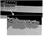
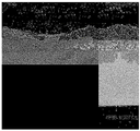
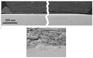
도 1은 8,600 시간의 스택 테스트 후, 금속 기판 지지된 SOFC의 주입구 측 상의 부식 생성물을 나타내는 SEM 단면 이미지를 도시한다. 기판 내로의 부식 침투(corrosion penetration)는 약 120㎛로 측정된다.
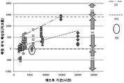
도 2는 600℃에서 최대 20,000 시간 동안의 테스트에서 여러 스택의 여러 전지 층 상에서 결정되는 가스켓 엣지(부식 전면(corrosion front)와 활성 전지 엣지(active cell edge) 사이의 거리로 측정)로부터의 기판 부식의 측면 전파(lateral propagation)을 도시한다.
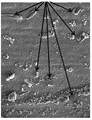
도 3은 14,600 시간 동안의 스택 테스트에서 전지의 주입구 측 상의 활성 셀 영역에 들어간 부식 전면을 도시하는 SEM 탑 다운(SEM top-down) 이미지를 도시한다.
도 4는 8600 시간의 스택 테스트에서 전지 상의 활성 전지 엣지(active cell edge)에 도달한 표면 균열(surface crack)이 부식을 강화시켜 이로 인한 보호 효과 손실의 영향을 보여주는 이미지를 도시한다. 균열의 끝 부분은 화살표로 표시된다.
도 5a 및 5b은 20,000 시간 동안의 스택 테스트에서 전지의 기판으로의 부식 투과(corrosion penetration)를 도시한다. 부식 침투 깊이는 약 200㎛이다.
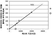
도 6은 SOFC 상의 주입구 가스켓 엣지(inlet gasket edge)에서 지속 시간 20,000 운전 시간까지의 SOFC 스택 테스트 범위로 측정된 기판으로의 부식의 투과 깊이(두께를 가로 지름)를 도시하며, 여기서 속이 찬 원은 얇은 코팅이 있거나 코팅이 없는 부식을 나타내고, 속이 막힌 원은 본 발명에서의 부식을 나타낸다.
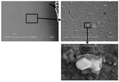
도 7a 및 7b은 주입구 가스켓 근처의 강(steel) 표면 상에 형성된 K2CrO4 상의 결절(nodules)을 보여주는 SEM 이미지를 도시한다. 화살표는 K2CrO4 증착물을 가리킨다.
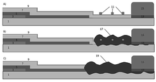
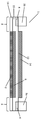
도 8은 Cr2O3 스케일과의 칼륨 반응을 통한 기판 부식의 성장, 표면에서 측면으로의 Fe2O3 스케일의 핵형성 성장(nucleation growth), 금속 기판 두께를 가로 지르는 Fe-Cr 기반 산화물의 내부 성장(inward growth)의 예상되는 메커니즘을 설명하는 개략도를 도시한다. 기판 (1); 애노드 (3); 전해질 (5); 중간층 (7); K2CrO4 핵 (11); 계면 부식 구역 (13); 가스켓 (15); K2CrO4 핵에서의 Fe가 풍부한 산화물 성장 (17); Fe2O3 성장 (19). 도면은 위에서 아래로 각각 200시간, 3000시간, 및 6000시간 후의 효과를 도시한다
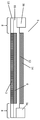
도 9a는 가스켓 유도 부식(gasket-induced corrosion)을 완화시키는데 적당한 구조를 갖는 본 발명의 SOFC를 통과하는 단면을 도시하는 개략도를 도시한다.
도 9b는 가스켓 유도 부식을 완화시키는데 적당한 대안적 구조를 갖는 본 발명의 SOFC를 통과하는 단면을 도시하는 개략도를 도시한다.
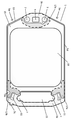
도 10은 본 발명의 SOFC 상에 도포된 Co-CGO 코팅의 레이아웃을 나타내는 기술 도면이다. 가스켓 접촉 영역은 파선으로 그려진 음영 영역으로 표시된다.
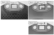
도 11a, 도 11b, 및 도 11c는 본 발명의 SOFC 상의 주입구 가스켓 주위에서 성장한 부식의 정도를 나타내며, 여기서 전지는 630°C에서 1000 시간 동안 가속 부식 테스트한 (a) 코팅되지 않은 기판, (b) 코팅된 기판 및 알루미늄 포일 배리어 층을 더 포함하는 코팅된 기판을 나타낸다.
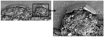
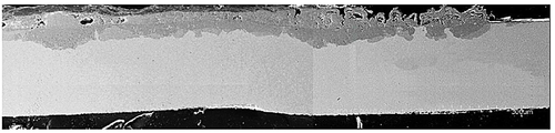
도 12는 630℃에서 1000 시간 동안 가속 부식 테스트한 후의 스택 레이어의 주입구 측을 나타내는 연마된 단면의 SEM 이미지를 도시한다. 기판 부식은 가스켓 엣지에서 시작하여 약 4mm 측면으로 전파되고 약 120㎛ 깊이로 관통한다. 이 부식 단계는 정상 스택 작동에서 약 12,000 시간에 해당한다.
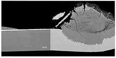
도 13은 630℃에서 1000 시간 동안 가속 부식 테스트를 한 후의 스택 레이어의 주입구 측을 나타내는 연마된 단면의 SEM 이미지를 도시한다. 이 부식 단계는 정상 스택 작동에서 약 12,000 시간에 해당한다. 기판 상에 도포된 Co-CGO 전해질 층은 완전 조밀 코팅(fully dense coating)으로 소결됨으로써, 가스켓 유도 기판 부식(gasket induced substrate corrosion)에 대하여 안정되고 효과적인 배리어을 형성한다. CGO는 기판의 공기 측 상의 가스켓 폭의 절반만을 커버하였다. 연료 측 가스켓은 강(steel)과 직접 접촉 하였지만, 기판의 환경 측면을 감소 시키는 것에 있어서 매우 낮은 산소 활성으로 인하여 어떠한 계면 부식도 일으키지 않았다.
도 14는 630℃에서 1,000 시간 동안 가속 부식 테스트 후 스택 층의 주입구 측을 나타내는 연마된 단면의 SEM 이미지로서, 기판 상에 알루미늄 중간층이 도포된 완전 조밀 Co-CGO 전해질 코팅을 도시한다.
도 15는 상기 기판의 공기 주입구 측에서 나타낸 Flexitallic T866 가스켓 구역 주변의 CGO 표면 상에 증착된 불소 함유 SiO2 불순물 상을 도시하는 이미지이다. CGO 표면 상의 SiO2의 결정 성장이 고배율로 분해된다.
도 16은 630℃에서 8,600 시간 동안 스택에서 테스트한 기판의 SEM 단면 이미지를 도시한다.
도 17은 (a)와 (b)는 스택 테스트에서 6100 시간 동안 테스트 한 전지의 주입구 가스켓 근처 영역에서 부식 생성물을 도시하는 SEM 이미지이다. (c)와 (d)는 (a)에 나타난 영역에서 K와 Si의 분포를 나타내는 원소지도이다. 합성 이미지 (b)에서, 녹색 영역은 기판 표면 상의 크로미아 스케일과 반응한 잔류 Flexitallic T866 가스켓 물질을 나타내고, 적색 영역은 상기 가스켓으로부터 휘발된 K와 크로미아 스케일의 반응에 의해 형성된 K2CrO4 표면 층을 나타낸다. (a)에서 이미지의 왼쪽에 있는 곡선 부분은 전해질로 성장하는 Fe2O3의 영역이다.The invention will now be described with reference to the following drawings and specific descriptions.
Figure 1 shows a SEM cross-sectional image showing corrosion products on the inlet side of a metal substrate supported SOFC after 8,600 hours of stack testing. The corrosion penetration into the substrate is measured to be about 120 탆.
Figure 2 is a graph of the effect of substrate corrosion (as measured by the distance between the corrosion front and the active cell edge), which is determined on several stacks of multiple cell layers at 600 < 0 > (Lateral propagation).
Figure 3 shows an SEM top-down image showing the erosion front entering the active cell area on the inlet side of the cell in the stack test for 14,600 hours.
Figure 4 shows an image showing surface cracks reaching an active cell edge on a cell in a 8600 hours stack test to enhance corrosion and thereby affect the loss of protective effect. The end of the crack is indicated by an arrow.
Figures 5a and 5b show the corrosion penetration of the cell to the substrate in a stack test for 20,000 hours. The depth of corrosion penetration is about 200 μm.
Figure 6 shows the penetration depth (across the thickness) of the corrosion into the substrate measured at the SOFC stack test range from the inlet gasket edge on the SOFC to a run time of 20,000 dpi, Indicates a corrosion with or without a thin coating, and a closed circle indicates corrosion in the present invention.
Figures 7a and 7b show SEM images showing nodules on K 2 CrO 4 formed on a steel surface near the inlet gasket. Arrows indicate K 2 CrO 4 deposits.
Figure 8 shows the growth of substrate corrosion through potassium reaction with Cr 2 O 3 scale, the nucleation growth of Fe 2 O 3 scale from the surface to the side, the formation of Fe-Cr based oxide across the metal substrate thickness ≪ / RTI > FIG. 5 shows a schematic diagram illustrating the expected mechanism of inward growth. A
FIG. 9A shows a schematic view showing a cross-section through the SOFC of the present invention having a structure suitable for mitigating gasket-induced corrosion.
Figure 9b shows a schematic view showing a cross-section through the SOFC of the present invention having an alternative structure suitable for mitigating gasket induced corrosion.
10 is a technical drawing showing the layout of a Co-CGO coating applied on the SOFC of the present invention. The gasket contact area is indicated by a shaded area drawn with a dashed line.
Figures 11a, 11b and 11c show the degree of corrosion developed around the inlet gasket on the SOFC of the present invention, wherein the cell was subjected to accelerated corrosion test at 630 ° C for 1000 hours (a) uncoated substrate, (b ) Coated substrate and an aluminum foil barrier layer.
12 shows a SEM image of the polished cross section showing the injection port side of the stack layer after accelerated corrosion test at 630 DEG C for 1000 hours. Substrate corrosion begins at the gasket edge and propagates about 4 mm laterally and penetrates to a depth of about 120 μm. This corrosion step corresponds to about 12,000 hours in normal stack operation.
Figure 13 shows an SEM image of the polished cross section showing the injection port side of the stack layer after accelerated corrosion test at 630 占 폚 for 1000 hours. This corrosion step corresponds to about 12,000 hours in normal stack operation. The Co-CGO electrolyte layer applied on the substrate is sintered by fully dense coating, thereby forming a stable and effective barrier against gasket induced substrate corrosion. The CGO covered only half of the gasket width on the air side of the substrate. The fuel side gasket was in direct contact with steel, but did not cause any interfacial corrosion due to very low oxygen activity in reducing the environmental aspects of the substrate.
14 is a SEM image of the polished cross-section showing the inlet side of the stack layer after an accelerated corrosion test at 630 DEG C for 1,000 hours, showing a fully dense Co-CGO electrolyte coating with an aluminum interlayer on the substrate.
15 is an image showing the fluorine-containing SiO 2 impurity phase deposited on the CGO surface in the vicinity of the Flexitallic T866 gasket zone shown on the air inlet side of the substrate. The crystal growth of SiO 2 on the surface of the CGO is decomposed at a high magnification.
16 shows a SEM cross-sectional image of a substrate tested in a stack for 6,600 hours at 630 < 0 > C.
17 (a) and (b) are SEM images showing corrosion products in the region near the inlet gasket of the cell tested for 6100 hours in the stack test. (c) and (d) are elemental maps showing the distribution of K and Si in the region shown in (a). In the composite image (b), the green region represents the residual Flexitallic T866 gasket material reacted with the chromia scale on the substrate surface, and the red region represents the K 2 CrO 4 surface formed by the reaction of K and chromia scale volatilized from the gasket Layer. (a), the curve on the left side of the image is the region of Fe 2 O 3 growing into the electrolyte.
도 2에서 숫자는 다음을 나타낸다.In Fig. 2, the numbers indicate the following.
(i) 전지의 전기화학적 활성 영역;(i) an electrochemically active region of the cell;
(ii) 알려진 결함이 있는 코팅되지 않거나 매우 얇은 코팅 상의 부식;(ii) corrosion on a coating that is not coated or has a known thin defect;
(iii) 얇은 코팅을 갖고 거의 결함이 없는 부식;(iii) corrosion with thin coating and little defect;
(iv) 본 발명에 따른 부식;(iv) corrosion according to the present invention;
(v) 전기화학적 활성 영역을 둘러싸는 주 전해질 층 영역;(v) a main electrolyte layer region surrounding the electrochemically active region;
(vi) 가스켓과 전해질 층이 코팅된 영역 사이의 영역.(vi) the area between the gasket and the area coated with the electrolyte layer.
도 9a는 영국 특허 제2 368 450호에 기술된 것과 유사한 본 발명의 금속 지지된 SOFC(1)을 통과하는 단면도의 계통도를 도시한다. 상기 SOFC는 페라이트계 스테인레스 강 기판(13)을 포함하며, 비 다공성 금속 포일로 제조되고 비 천공 영역(non-perforated region)로 둘러싸인 천공 영역(perforated region)으로 구성되며, 여기서 상기 천공 영역은 상기 기판의 영역(2)을 통하여 수 천 개의 구멍을 레이저 천공(laser-drilling)하여 형성된 개구(apertures)로 형성된다. 크롬 산화물 부동태 층(chromium oxide passivation layer)(도시되지 않음)은 상기 기판과 애노드 층 사이에 형성된다. 영국 특허 제2 368 450호, 영국 특허 제2 517 927호, 영국 특허 제2 517 928호에 기재된 것과 유사한 적어도 기판(13)의 영역(2)을 커버하는 니켈 산화물 및 Co-CGO 다공성 애노드 층(6)이 제공된다. 상기 애노드 층(6) 위에는 영국 특허 제2 524 640호에 기재된 것과 유사한 Co-CGO 전해질 층(15)(10 내지 20 ㎛ 두께)이 증착되며, 이는 상기 기판(13)의 비 천공 구역(8) 상에 애노드 층 (6)과 겹쳐지며(overlap), 이로써 상기 애노드 층(6)의 엣지 주변에 밀봉을 형성한다. 상기 캐소드 층(19)(도 12 참조)은 몇몇의 층, 산소의 환원이 일어나는 제1 얇은 캐소드 활성 층(12), 및 스택의 전지(1)로부터 전류를 모으도록 하는 더 두꺼운 캐소드 전류 컬렉터 층(14)(도시되지 않음)으로 구성된다. 상기 가스켓(3a, 3b)은 알루미늄 포일 배리어 층(4)을 통하여 전해질 층(15)에 연결된다. 금속 인터커넥트(interconnect)(도시되지 않음)는 용접과 같은 당 업계에 공지된 다양한 수단에 의하여 금속 기판에 연결될 수 있다. 상기 인터커넥트는 일반적으로 비 천공 영역(8)의 부분과 같은 전지 반응에 관여하지 않는 전지의 부분에 부착된다. 상기 인터커넥트는 일반적으로 금속 인터커넥트 상의 접촉 부분(feature)과 전류 콜렉터 층(14) 사이에 전기적 접촉이 이루어져 상기 가스켓(3a, 3b)을 밀봉한다. 상기 가스켓은 전기적으로 절연되어 있다. 이를 통하여 다수의 SOFC가 SOFC 스택으로 연결될 수 있으며, 상기 SOFC 스택의 각 개별 SOFC 주위에서 격리된 반응 환경(isolated reaction environment)이 생성된다.9A shows a schematic diagram of a cross-section through a metal supported
도 9b는 배리어 층(4)(도 9a에서 가스켓 아래에 도시됨)이 사용되지 않고 전해질 층(15)만이 부식 억제 층(corrosion inhibiting layer)으로 작용하는 대안적인 배열을 도시한다.Figure 9b shows an alternative arrangement in which the barrier layer 4 (shown below the gasket in Figure 9a) is not used and only the
도 10은 페라이트계 스테인레스 강 기판(13)을 코팅하는 코발트 도핑된 세륨 가돌리늄 산화물(Co-CGO)(15)의 전해질 층을 더 포함하는 단일 페라이트계 스테인레스 강 기판(13)을 포함하는 SOFC(1)로 구성된 본 발명의 예시적인 구현예를 도시한다. 가스켓(3a, 3b)은 상기 전해질 층(15)에 도포된다. 상기 전해질 층 (15)은 실질적으로 모든 기판을 커버하여, 대략 1mm의 폭을 갖는 SOFC의 둘레 주위에 코팅되지 않은 기판의 좁은 영역을 남긴다. 상기 전해질 층은 또한 상기 가스켓 아래로 연장된다(그림 9a 참조). 또한 상기 가스켓(3a, 3b)에 근접한 영역(17a, 17b, 17c)이 도시되는데, 전해질 층 코팅(15)을 포함하는 것이 특히 바람직하다. 이들은 일반적으로 가스켓으로부터 불순물이 배출되어 증착된 영역이다. 캐소드 층(19)은 상기 전해질 층 (15)의 표면 상에 증착된다. 상기 기판과 전해질 사이의 애노드 층은 도시되지는 않았지만, 캐소드 층 (19) 상태와 대략적으로 대응될 것이다.10 is a cross-sectional view of a SOFC 1 (Fig. 1) including a single ferritic
상기 가스켓은 공기 주입구(5a), 압축 수단 고정체가 상기 가스켓을 통과하고 가스 밀봉 및 전기 접촉(7) 및 공기 배출구(21)를 위한 상기 SOFC 스택 층을 물려 잡도록(clamp) 한다. 연료 주입구(9) 및 연료 배출구(11) 또한 제공된다. SOFC 제조시 전해질 층과의 접촉이 만들어지지 않고도 SOFC를 다룰 수 있게 하는 비 코팅 영역 (5d)이 또한 SOFC에 제공된다. 신용 표시(fiduciary mark)(5b)는 제조 공정 단계 정렬에 도움을 준다. 구성 5c 또한 제조 공정 단계 정렬을 도우며 각 SOFC의 제조 및 조립과 구체적인 사후 테스트 분석을 수행하는 동안 품질 데이터 트랙킹(quality data tracking)을 가능케 하는 물리적 표시 식별자(physical mark identifiers)를 위한 위치를 제공한다. 구성 5c는 SOFC 스택이 조립될 때 SOFC를 밀접한 적절한 정렬로 유지하는 수신 요소(receiving element)(도시되지 않음)와 협동하도록 만들어질 수 있기 때문에, 또한 다수의 SOFC를 SOFC 스택으로 배열하는데 사용된다. 상기 전해질 층은 대략 12.5㎛의 두께를 가지고 상기 가스켓은 질석-활석 조성물로부터 제조된다. 특히 450-650℃ 범위로 SOFC가 작동되는 경우, 사용되는 가스켓은 T866을 비롯한 Flexitallic Ltd 사로부터 입수할 수 있는 것과 같은 질석-탈크 기반 가스켓일 수 있다.The gasket clamps the SOFC stack layer for
SOFC(1)은 니켈 산화물 분말 및 Co-CGO 분말의 현탁 입자를 함유하는 스크린 프린팅 잉크를 기판 (13)에 도포하여 제조되었다(D90 = 0.7 내지 1.2㎛, 잉크 중의 니켈 산화물 대 Co-CGO의 비는 1 : 1.5 임). 상기 잉크는 통상적인 방법을 사용하여 페라이트계 스테인레스 강 기판 상에 스크린 프린트되었고, 오븐에서 건조되어 용매를 증발시키고 바인더를 경화시켜 두께 9 내지 15 ㎛의 건조된 프린트 층을 형성 하였다. 상기 건조된 프린트 층은 오븐에서 300 내지 500℃ 범위의 온도로 가열되었고, 상기 잉크 중의 유기 바인더를 연소시키고 300 ㎫의 압력에서 냉간 정수압 압축(cold isostatic pressing)을 사용하여 그린 애노드 층(green anode layer)을 남겼다. 상기 압축된 그린 애노드 층은 노(furnace)에 넣고 공기 분위기에서 1020℃의 온도로 45 분 동안 가열하였고, 견고하고 잘 소결된 애노드 층(6)을 제조 하였다. Co-CGO 전해질 층(15)은 상기 애노드 층(6) 상에 스크린 프린트 되었고, 1020℃의 노에서 45 분간 소성(fired)되었다. 마지막으로, 지르코니아 층을 소성된 전해질 층 상에 스크린 프린트한 다음, 1020 ℃의 온도에서 소성하기 전에 도핑된 세리아 층 및 2개의 캐소드성 층(cathodic layer)을 스크린 프린트하여 캐소드 층(19)을 제조 하였다.The
실시예Example
본 발명의 전지를 사용하는 SOFC 스택은 압축 밀봉을 채용하여 연료 측 반응물 가스를 공기 측 반응물 가스로부터 격리시킬 수 있으며, 예컨대 Flexitallic 사에서 공급하는 T866 질석-탈석 기반 가스켓을 사용하여 격리시킬 수 있다. 이러한 압축 밀봉은 상기 SOFC 스택의 SOFC들 사이에서 상기 가스켓을 1 - 50 MPa의 압축력을 사용하여, 더 일반적으로 실온에서(즉, 5 내지 30 ℃ 범위) ~ 20 MPa 압축력을 사용하여 물리적 압축할 것을 요구한다. 본 기술 분야의 통상의 기술자는 밀봉력, 밀봉력 어플리케이션 메커니즘, 가스켓 디자인, 및 SOFC 디자인에서 요구되는 밀봉력의 수준이 결정되는 것으로 인식할 것이다. 도 10에 도시된 SOFC는 가스켓(3a, 3b)에 압축력을 가하기 위해 SOFC 스택 층을 관통하는 타이 바(tie-bar)를 채용한다. 상기 압축 타이 바(도시되지 않음)는 상기 스택 설계에서 가스 밀봉에 효과적인 압축 하중과 상기 가스켓의 압축 높이을 적용하도록 하는 위치인 상기 SOFC 층의 위치 7을 관통하였다. The SOFC stack using the cell of the present invention may employ a compression seal to isolate the fuel side reactant gas from the air side reactant gas and may be isolated using, for example, the T866 vermiculite-depleted gasket supplied by Flexitallic. This compression seal may be accomplished by physically compressing the gasket between SOFCs of the SOFC stack using a compressive force of 1 - 50 MPa, more typically using a compressive force of ~ 20 MPa at room temperature (i.e., in the range of 5 to 30 캜) Demand. One of ordinary skill in the art will recognize that the level of sealing force required in the sealing force, sealing force application mechanism, gasket design, and SOFC design is determined. The SOFC shown in FIG. 10 employs a tie-bar penetrating the SOFC stack layer to apply a compressive force to the
몇몇 SOFC 스택 테스트의 데이터에서 일반적인 SOFC 금속 기판 아래, 상기 기판의 공기 층 상의 가스켓 접촉 영역(도 10의 영역 (17a, b, c)과 같은 가스켓에 근접한 영역) 내부와 그 주위의 부식, 상기 기판 금속의 영향을 받는 구역의 다공성 산화물 스케일으로의 변환을 밝혔다. 몇몇 SOFC 스택 층의 테스트 후 특성으로부터 생성된 데이터에서 상기 공기 측 상의 가스켓 접촉 영역의 내부와 그 주위의 상기 강(steel) 표면은 SOFC 작동의 공기 측 가스켓으로부터 휘발된 칼륨(K), 불소(F), 및 실리콘(Si)을 포함하는 부식성 종(corrosive species)에 노출됨을 확인하였다. In some SOFC stack test data, corrosion under and around a conventional SOFC metal substrate, inside and around a gasket contact area on the air layer of the substrate (near the gasket, such as
전술한 바와 같이 전해질 중간층 및 상부 CGO로부터의 전해질 물질의 나노미터 단위의 얇은 층을 갖는 공기 측 상의 상기 강(steel)의 몇몇 표면 커버리지(전지 엣지에서의 중간층 씻김(interlayer wash off)이라고도 함)에도 불구하고, 이러한 얇고 결함있는 코팅으로는 부식 효과, 예를 들어 K- 및 F- 함유 기상 종의 부식 효과를 방지할 수 없다. 부식은 예를 들어, 전지 엣지의 결함있는 영역의 상부 상에 있는 Fe2O3 결절의 핵 형성에 의하여 개시되고 상기 결절의 유착에 의하여 성장한다. Some surface coverage (also referred to as interlayer wash off at the cell edge) of the steel on the air side with a thin layer of nanometer units of electrolyte material from the electrolyte interlayer and top CGO as described above Nevertheless, such thin, defective coatings can not prevent corrosion effects, for example the corrosive effects of K- and F-containing gaseous species. Corrosion is initiated, for example, by nucleation of the Fe 2 O 3 nodule on the top of the defective area of the cell edge, and grows by adhesion of the nodule.
상기 부식은 두가지 방식으로 전파된다:The corrosion is propagated in two ways:
(i) 가스켓 엣지로부터 활성 셀 영역을 향하여 X-Y 평면 상에 퍼지는 부식(즉, 전지 표면을 가로 지르는 측면 전파). 일단 부식이 개시되면, 이는 작동 기간 동안 지속되고, 심지어 (부식 속도는 느려지만) 강(steel) 표면 위로 연장된 전해질 층 아래로 계속된다.(i) Corrosion (i.e., lateral propagation across the cell surface) that spreads from the gasket edge toward the active cell area on the X-Y plane. Once erosion is initiated, it lasts for the duration of the operation and continues even below the electrolyte layer that extends over the steel surface (although the corrosion rate is slow).
(ii) 상기 공기 측으로부터 기판의 연료 측을 향하여 Z-축을 따라 진행되는(advancing) 부식(즉, 전지 두께를 가로 질러 연료를 통과하는 투과).(ii) corrosion advancing along the Z-axis from the air side toward the fuel side of the substrate (i.e., permeation through the fuel across the cell thickness).
두 경우 모두 부식 효과는 주로 Fe-Cr계 산화물의 내부 성장(inward growth)과 주로 Fe2O3의 외부 성장(outward growth)에 의해 발생하는데, 이는 보호 Cr2O3-스피넬 층이 결함 있는/비보호 층으로 되는 지점에서의 외부 Cr 확산 및 산소 이온 확산의 산물이라고 생각된다.In both cases, the corrosion effect is mainly caused by the inward growth of Fe-Cr oxide and the outward growth of Fe 2 O 3 , which is due to the fact that the protective Cr 2 O 3 - It is thought to be the product of external Cr diffusion and oxygen ion diffusion at the point where it becomes an unprotected layer.
전술한 특징은 8,600 시간 작동으로 SOFC 스택에서 테스트한 SOFC의 주입구 측 상의 가스켓 엣지에서 발생된 부식 생성물을 도시하는 도 1의 SEM 단면 이미지로 예시된다. 본 섹션은 전해질 형성 공정에서 물질이 "씻겨 나온" 물질의 결과물인 얇은(<1 미크론) 전해질 물질을 도시한다. 이러한 결과는 6,100 시간 작동으로 테스트한 다른 SOFC 스택에서 테스트한 전지 상의 가스켓 엣지에서 부식 전면의 모습을 나타내는 3D Keyence 광학 이미지로 보완된다.The above-mentioned feature is exemplified by the SEM cross-sectional image of Fig. 1 showing the corrosion products generated at the gasket edges on the inlet side of the SOFC tested in the SOFC stack with 8,600 hours of operation. This section shows a thin (<1 micron) electrolyte material that is the result of a material "washed out" in the electrolyte formation process. This result is complemented by a 3D Keyence optical image that shows the appearance of the erosion front on the gasket edge on the cell tested on another SOFC stack tested for 6,100 hours of operation.
도 1의 SEM에 도시되는 바와 같이, 부식은 얇은 코팅 층 아래에서 계속되는 Fe2O3 스케일의 유착과 성장에 의하여 X-Y 및 Z 방향으로 전파된다.As shown in the SEM of Fig. 1, corrosion propagates in the XY and Z directions due to subsequent adhesion and growth of Fe 2 O 3 scale below the thin coating layer.
다른 SOFC 스택에서 테스트된 SOFC 전지에서 발달한 이들 특징의 다양한 예시들이 도 12 내지 도 17에 도시 된 SEM 이미지에 나타난다.Various examples of these features developed in SOFC cells tested in different SOFC stacks are shown in the SEM image shown in Figs. 12-17.
가스켓 유도 부식의 메커니즘Mechanism of Gasket Induction Corrosion
가스켓 유도 기판 부식에 대한 여러 메커니즘이 고려되었다. 이론에 얽매이지 않고 가장 가능성 있는 메커니즘은 다음 두 가지 명제로 설명 할 수 있다:Several mechanisms for gasket induced substrate corrosion have been considered. The most probable mechanisms that are not bound by theory can be explained by two propositions:
(i) 증기 보조된 크롬(Cr) 고갈(steam-aided chromium depletion)은 부식을 활성화시킨다: 잔여 연료 누설로 인하여 가스켓에서 방출된 스팀은 상기 기판 표면 상의 국소 Cr 휘발(local Cr volatilisation)을 일으켜 Cr 고갈에 의한 보호성 Cr2O3 표면 스케일을 저하시킨다. 표면에서 Fe2O3 결절의 핵 형성이 가능할 정도로 Cr 고갈이 한 영역에서 충분히 커지면 부식이 시작된다. 그러면 부식은 그러한 결절의 성장과 유착에 의해 시간이 지나면서 진행될 수 있다. 도 8에 도시된 전지 사진은 630℃에서 1000 시간 동안의 부식 테스트 동안 발달된 상기 주입구 가스켓 주변의 스팀 효과를 나타낸다.(i) Steam-assisted chromium depletion activates corrosion: Steam released from the gasket due to residual fuel leakage causes local Cr volatilisation on the substrate surface, resulting in Cr Decreases the surface scale of protective Cr 2 O 3 by depletion. Corrosion begins when the Cr depletion is large enough in one region to nucleate Fe 2 O 3 nodules at the surface. Corrosion can then progress over time by the growth and adhesion of such nodules. 8 shows the steam effect around the inlet gasket developed during the corrosion test for 1000 hours at 630 ° C.
(ii) 휘발성 가스켓 불순물은 부식을 활성화 시킨다: K, F, Si, 황(S)과 같은 특정 불순물은 상기 가스켓으로부터 휘발되어, Cr2O3 스케일과 반응하여 Fe2O3 스케일이 성장할 수 있는 결함이 있는 지점으로 발달될 수 있다.(ii) volatile gasket impurity activates corrosion: K, F, Si, sulfur certain impurities, such as (S) is volatilized from the gasket reacts with Cr 2 O 3 scale to grow the Fe 2 O 3 scale It can develop into a defective spot.
두 메커니즘 모두는 함께 작동하여 관찰된 부식 효과를 일으키는 것으로 여겨진다. 상기 가스켓 내부의 연료와 휘발성 종 사이의 상호 작용의 본질은 여전히 알려지지 않았다. 그럼에도 불구하고, 휘발성 종은 수소 또는 가스켓 내부에서 산소와 수소가 만나는 곳에서 형성되는 수증기와 반응 할 수 있고 스택에서 가열하는 동안 부식 유발 종의 방출을 활성화하는 것으로 가정하는 것이 합리적이다. 일부 테스트된 전지에서 수행된 원소 분석을 통하여 K, F 및 Si의 트레이스(trace)가 상기 가스킷 접촉 영역 주위에 화합물을 형성한다는 사실 이 밝혀졌으며, 이는 이들 원소가 휘발되어 가스켓으로부터 공급되고 상기 기판 표면과 상호 작용하여 부식을 촉진시킴을 나타낸다. 사후 테스트 분석은 K가 표면 스케일의 Cr과 반응하여 강(steel) 표면 상의 K2CrO4 상의 결절을 형성함을 나타내며, 도 9a에서 SEM-EDX 데이터로부터의 증거를 나타낸다. 표면 스케일의 Cr과 반응한 K가 상기 강(steel) 표면 상에서의 Fe2O3 핵 형성에 중요한 지점을 창출하는 것으로 보인다. 그런 뒤, 부식은 상기 표면에서 측면으로의(laterally) 유착과 성장 및 강(steel) 두께를 가로지르는 Fe-Cr 기반 산화물의 내부 성장에 의하여 전파될 수 있다. 이러한 단계는 미세 구조 관측 기반의 도 10에 나와 있다.Both mechanisms are believed to work together to produce observed corrosion effects. The nature of the interaction between the fuel and the volatile species inside the gasket is still unknown. Nonetheless, it is reasonable to assume that volatile species can react with water vapor formed at the junction of oxygen and hydrogen within a hydrogen or gasket and activate the release of corrosion-inducing species during heating in the stack. It has been found through the elemental analysis carried out in some tested cells that traces of K, F and Si form compounds around the gasket contact area, which means that these elements are volatilized and fed from the gasket, And accelerates corrosion. The post test analysis shows that K reacts with Cr on the surface scale to form nodules on K 2 CrO 4 on the steel surface and shows evidence from the SEM-EDX data in FIG. 9A. It appears that K reacting with Cr on the surface scale creates an important point for Fe 2
마찬가지로, 상기 가스켓 통하여 확산된 수소와 반응하는 F는 강 및 합금에 대해 매우 부식성 있는 HF의 증기를 형성 할 수 있다. 테스트된 기판과 전지에서 플루오린 유도 기판 부식을 확인할 수 있는 직접적인 증거는 발견되지 않았다. 그러나 1000시간 동안 테스트된 CGO 코팅 기판에 대한 최근의 WDS 분석에서는 가스켓 엣지 주변의 CGO 코팅 표면에 증착된 F가 풍부한 SiO2 상을 나타내므로 F가 부식에 미치는 영향은 실제적인 것으로 나타났다.Similarly, F reacting with hydrogen diffused through the gasket can form a highly corrosive HF vapor for the steel and the alloy. No direct evidence of fluorine-induced substrate corrosion in the tested substrates and cells was found. However, the recent WDS analysis of the CGO coated substrates tested for 1000 hours showed F-rich SiO 2 phase deposited on the CGO coated surface around the gasket edge, so the effect of F on corrosion was real.
기판 상에 CGO 코팅을 제조CGO coating on substrate
다수의 레이저 천공 금속 기판(substrates laser drilled metal)은 표준 세정 및 TGO 열처리 공정을 거쳤다. 이들 기판은 그런 뒤 전지 상에 전해질 층을 제조하기 위하여 도포하는 것처럼 3층 레이저 스크린 프린팅 방법으로 상기 Co-CGO 전해질 잉크로 코팅되었다. 각 프린트는 다은 프린트 층이 추가되지 전에 200℃에서 건조되었다. 이어서 압축(pressing)과 그런 뒤 바인더 소각 단계(binder burn out step)를 포함하여 1020℃에서 표준 공기 전해질 소성하였다.Many laser drilled metal substrates have undergone standard cleaning and TGO heat treatment processes. These substrates were then coated with the Co-CGO electrolyte ink in a three-layer laser screen printing process as if they were applied to produce an electrolyte layer on the cell. Each print was dried at < RTI ID = 0.0 > 200 C < / RTI > Followed by standard air electrolyte firing at 1020 ° C, including pressing followed by a binder burn out step.
상기 소결된 전해질 층은 박리(delamination), 균열(crack), 또는 치핑 손상(chipping damage)의 징후 없이 12.5㎛ 두께이고 완전 조밀하였다. CGO 스크린 프린팅을 통하여 CGO 코팅이 도 12의 도면에 도시된 바와 같이 기판 엣지에 매우 근접하게 접근 할 수 있도록 하였다. 취급을 용이하게 하고 우발적인 코팅 손상을 방지하기 위하여 상기 기판 엣지와 CGO 코팅 엣지 사이에 1 mm의 틈을 남겼다.The sintered electrolyte layer was 12.5 μm thick and completely dense without any signs of delamination, cracking, or chipping damage. CGO screen printing allows the CGO coating to be accessed very close to the substrate edge as shown in the drawing of FIG. A gap of 1 mm was left between the substrate edge and the CGO coating edge to facilitate handling and prevent accidental coating damage.
Co-CGO 코팅 기판의 가속 부식 테스트(ACT)Accelerated Corrosion Test (ACT) of Co-CGO Coated Substrate
Co-CGO 코팅 기판은 Ceres Power Limited에서 개발된 표준 가속 SOFC 부식 테스트를 수행 하였다. 가속 부식 테스트는 SOFC 스택 작동을 모방한다. 즉, 모든 SOFC 층은 상기 SOFC의 각각의 채널에서 습한 공기/습한 H2의 연속 흐름으로 제공되는 이중 분위기에 노출되고 인터커넥트 및 비천공 기판을 갖는 더미 층(dummy)으로서 제조된다. 부식 가속은 630℃에서 가속 부식 테스트를 수행하고 상기 스택의 공기 측이 습한 공기(워터 버블러(water bubbler)를 통하여 유입되는 대기)에 노출시킴으로써 유발된다. 부식 평가는 미코팅 기판에 대하여 이러한 가속 부식 테스트를 사용하여 수행되며 실제 SOFC 스택 테스트를 거친 SOFC와 결과를 비교하여 이러한 테스트에 적용된 가속 부식 조건이 570 내지 610 ° C의 온도 범위에서 실제 SOFC 스택 테스트 후 통상적으로 발견되는 가스켓 유도 부식 프로세스보다 대략 12배의 가속을 제공한다는 사실이 밝혀졌다. 따라서, 1000시간의 가속 부식 테스트는 12,000시간의 정상적인 SOFC 작동과 동등한 것이다.Co-CGO coated substrates were subjected to a standard accelerated SOFC corrosion test developed by Ceres Power Limited. The accelerated corrosion test mimics the operation of the SOFC stack. That is, all the SOFC layers are exposed as a dummy atmosphere, which is provided in a continuous stream of humid air / humid H 2 in each channel of the SOFC, and are fabricated as dummies with interconnect and unperforated substrates. Corrosion acceleration is caused by performing an accelerated corrosion test at 630 ° C and exposing the air side of the stack to humid air (the atmosphere through which water bubbles enter). Corrosion tests were performed on these uncoated substrates using these accelerated corrosion tests and compared the results with actual SOFC stack tested SOFCs. The accelerated corrosion conditions applied to these tests were the actual SOFC stack test at a temperature range of 570-610 ° C It has been found that it provides about 12 times more acceleration than the gasket induced corrosion processes commonly found after the process. Thus, the 1000 hour accelerated corrosion test is equivalent to a normal SOFC operation of 12,000 hours.
이 연구에서, (i) 미코팅 기판, (ii) Co-CGO 코팅 기판, (iii) 알루미늄 포일과 결합된 Co-CGO 코팅 기판을 포함하는 9층의 부식 스택은 Flexitallic T866 가스켓으로 조립되었다. 상기 SOFC 스택의 가속 부식 테스트는 630℃에서 1,000시간 동안 수행되었다. 가속 부식 테스트를 마친 뒤, SEM 특성 분석 및 EDX 원소 분석을 통하여 선택된 전지 층에서 사후 테스트 특성화 과정을 수행하였다.In this study, a nine-layer corrosion stack including (i) uncoated substrate, (ii) Co-CGO coated substrate, and (iii) Co-CGO coated substrate bonded with aluminum foil was assembled with Flexitallic T866 gasket. The accelerated corrosion test of the SOFC stack was performed at 630 DEG C for 1,000 hours. After the accelerated corrosion test, a post test characterization process was performed on selected cell layers through SEM characterization and EDX element analysis.
Co-CGO 코팅의 기판 부식 방지Prevention of substrate corrosion of Co-CGO coating
도 13(a)의 SOFC 이미지에서 예시하는 바와 같이, 미코팅 기판에서는 630℃에서 1,000시간 동안 가속 부식 테스트하는 동안 가스켓 엣지 주변에서 심각한 부식을 겪었다. 기판 부식은 가스켓 엣지에서 시작하여, 약 4mm 측면으로 전파되고 약 120㎛ 깊이로 관통하였다. 부식의 이러한 단계는 약 12,000시간의 실제 SOFC 스택 작동에 해당한다. 반면, 동일한 SOFC 스택에서 테스트한 Co-CGO 전해질 코팅 기판은 부식이 발생하지 않았다(도 13(b) 및 (c)의 그림 및 도 14, 15, 및 16의 SEM 단면 이미지 참조).As illustrated in the SOFC image of Figure 13 (a), uncoated substrates suffered severe corrosion around the gasket edges during accelerated corrosion testing at 630 ° C for 1,000 hours. Substrate corrosion began at the edge of the gasket, propagated about 4 mm laterally and penetrated about 120 탆 deep. This step of corrosion corresponds to an actual SOFC stack operation of about 12,000 hours. On the other hand, the Co-CGO electrolyte-coated substrate tested on the same SOFC stack did not suffer corrosion (see Figs. 13 (b) and (c) and Figs. 14, 15 and 16, SEM cross-sectional images).
Flexitallic T866 가스켓과 Co-CGO 코팅 사이에 알루미늄 포일을 배치하여 상기 가스켓과 기판 사이에 배리어를 제공하여 가스켓이 맨 기판 표면과 정상적으로 접촉하는 영역(도12에 도시된 가스켓 아래 영역)에서 계면 부식 반응을 방지하는 것을 목표로 하였다. 상기 포일은 그 목적에 잘 부합하였다. 기판 강 및 가스켓 모두와 불활성 계면을 형성했으며, 테스트 후에 포일 보호 영역에서 부식 흔적이 발견되지 않았다(그림 16). 사용된 알루미늄 포일은 스택 어셈블리에서 단지 25㎛ 두께였으며, 이는 가스켓 압축 하에서 소성 변형(plastic deformation)/크리프(creep)로 인하여 스택 테스트 동안 약 10㎛로 감소되었다. 이러한 배열 구성(configuration)은 630℃에서 1,000 시간 동안 가속 부식 테스트에 노출되는 동안 기판 부식에 매우 효과적인 배리어를 제공한다.An aluminum foil is placed between the Flexitallic T866 gasket and the Co-CGO coating to provide a barrier between the gasket and the substrate to provide an interfacial corrosion reaction in the region where the gasket normally contacts the substrate surface (the region under the gasket shown in FIG. 12) . The foil was well suited for that purpose. Inert interfaces were formed with both the substrate steel and the gasket, and no signs of corrosion were found in the foil protection area after testing (Figure 16). The aluminum foil used was only 25 microns thick in the stack assembly, which was reduced to about 10 microns during the stack test due to plastic deformation / creep under gasket compression. This arrangement provides a barrier that is highly effective in substrate corrosion during exposure to accelerated corrosion test at 630 < 0 > C for 1,000 hours.
휘발된 불순물과 Co-CGO 코팅의 상호 작용Co-CGO Coating Interaction with Volatilized Impurities
T866 개스킷에서 휘발되는 주요 불순물 중, 기판 표면 위의 가스켓 부근의 Co-CGO 코팅 상에서 F와 Si만이 검출되었다. 표면 상에 성장된 불순물 상은 상당한 양의 F를 함유하는 결정질 SiO2이었다. 도 17에 나타난 SEM 이미지는 Co-CGO 표면 상에 성장된 SiO2 결정을 함유하는 F의 예시를 제공한다. 연마된 단면을 볼 때, 실리카 상은 고해상도 SEM 검사 조건 하에서 Co-CGO 코팅으로 투과되지 않았다. 원소 라인 스캔(elemental line sacns) 또한 코팅으로 어떠한 실리카도 상당량으로 투과하지 않음을 나타낸다. Co-CGO 코팅은 부식성 공격에 대하여, 특히 가스켓으로부터 휘발된 F- 및 Si- 함유 증기에 대하여 신뢰성을 갖는 배리어를 제공하는 것으로 보인다.Of the major impurities volatilized in the T866 gasket, only F and Si were detected on the Co-CGO coating near the gasket on the substrate surface. The impurity phase grown on the surface was a crystalline SiO 2 containing a significant amount of F. The SEM image shown in Figure 17 provides an illustration of F containing SiO 2 crystals grown on a Co-CGO surface. From the polished cross section, the silica phase was not penetrated by the Co-CGO coating under high-resolution SEM inspection conditions. Elemental line scans also indicate that the coating does not transmit any significant amounts of silica. The Co-CGO coating appears to provide a barrier against corrosive attack, especially for F- and Si-containing vapors volatilized from gaskets.
본 명세서에 기재된 각각의 정수(integer)는, 다른 기재가 없는 한, 당업계의 통상의 기술자가 이해하는 바와 같이 다른 정수와 조합하여 사용될 수 있다. 또한, 비록 본 발명의 모든 측면들이 바람직하게는 그 측면과 관련하여 기재된 특징들을 "포함하기는(comprise)" 하지만, 이들은 청구항에서 개략적으로 나타난 이들 특징들로 "구성되거나(consist)" 또는 "필수적으로 구성(consist essentially)"될 수 있다고 명확히 생각된다. 또한, 모든 용어는, 본 명세서에 특별히 기재되지 않는 한, 당업계에서 통상적으로 이해되는 의미를 제공하는 것으로 의도된다. Each integer described herein can be used in combination with other integers, as will be appreciated by one of ordinary skill in the art, unless otherwise indicated. Also, although all aspects of the present invention preferably " comprise " the features described in connection with that aspect, they are not intended to be "Quot; consist essentially " of < / RTI > In addition, all terms are intended to provide the meanings commonly understood in the art, unless otherwise specified herein.
또한, 본 발명의 논의에서, 상충되는 기재가 없는 경우, 변수의 허용 범위의 상한 또는 하한에 대한 대체값에 대한 기재는, 상기 대체값의 상한과 하한의 사이에 위치하는 상기 변수의 각각의 중간값이 또한 그 자체로도 그 변수에 대해 가능한 값으로 기재된 것이라고 암시된 문장으로 이해될 것이다.Further, in the discussion of the present invention, in the absence of a conflicting description, the description of the replacement value for the upper or lower limit of the permissible range of the variable may be written in the middle of each of the variables located between the upper and lower limits of the replacement value It will be understood that the value is also implied by itself as being a possible value for the variable.
또한, 다른 기재가 없는 한, 본 명세서에 기재된 모든 수치값(numerical value)은 "약(about)"이라는 용어에 의해 변경될 수 있는 것으로 이해될 것이다. 본 발명의 방법 및 장비는 다양한 방식으로 구현될 수 있고, 본 명세서에는 단지 몇몇 경우만 도시되고 기재된 것으로 이해되어야 할 것이다.It is also to be understood that, unless stated otherwise, all numerical values recited herein may be altered by the term " about. &Quot; The method and apparatus of the present invention may be implemented in a variety of ways, and it should be understood that only a few examples are shown and described herein.
Claims (25)
금속 기판;
상기 금속 기판에 인접한 전해질 층; 및
상기 금속 지지된 고체 산화물 연료 전지로 및/또는 상기 금속 지지된 고체 산화물 연료 전지로부터 유체가 전달되는 적어도 하나의 가스켓;을 포함하며,
상기 전해질 층은 상기 금속 기판의 부식을 방지하는 비 다공성 보호 코팅을 제공하고, 및
상기 전해질 층의 적어도 일부는 상기 기판과 상기 가스켓의 사이 및/또는 상기 가스켓에 근접한(proximate) 영역에서 상기 금속 기판 상에 위치하는, 연료 전지.A metal-supported solid oxide fuel cell comprising:
A metal substrate;
An electrolyte layer adjacent to the metal substrate; And
And at least one gasket through which fluid is transferred from the metal supported solid oxide fuel cell and / or the metal supported solid oxide fuel cell,
Wherein the electrolyte layer provides a non-porous protective coating to prevent corrosion of the metal substrate, and
Wherein at least a portion of the electrolyte layer is located on the metal substrate in a region between the substrate and the gasket and / or in a region proximate to the gasket.
상기 전해질 층은 상기 기판과 상기 가스켓 사이에 위치하는, 연료 전지.The method according to claim 1,
Wherein the electrolyte layer is positioned between the substrate and the gasket.
상기 전해질 층은 상기 가스켓에 근접한 영역에서 상기 기판 상에 위치하는, 연료 전지.3. The method according to claim 1 or 2,
Wherein the electrolyte layer is located on the substrate in a region close to the gasket.
보호 비 다공성 배리어 층을 더 포함하며, 상기 전해질 층은 상기 배리어 층과 상기 기판 사이에 위치하는, 연료 전지.4. The method according to any one of claims 1 to 3,
Further comprising a protective nonporous barrier layer, wherein the electrolyte layer is positioned between the barrier layer and the substrate.
금속 기판;
상기 전지로 및/또는 상기 전지로부터 유체가 전달되는 적어도 하나의 가스켓; 및
상기 기판의 부식을 방지하기 위한 보호 비-다공성 배리어 층;을 포함하며,
상기 배리어 층의 적어도 일부는 상기 가스켓에 근접한 영역에서 상기 기판 상에 위치하는, 연료 전지.A metal-supported solid oxide fuel cell comprising:
A metal substrate;
At least one gasket through which fluid is delivered to and / or from the battery; And
And a protective non-porous barrier layer for preventing corrosion of the substrate,
Wherein at least a portion of the barrier layer is located on the substrate in an area adjacent to the gasket.
상기 배리어 층은 상기 가스켓에 근접한 영역에서 상기 기판 상에 위치하고 상기 기판과 상기 가스켓의 사이에 위치하는, 연료 전지.The method according to claim 4 or 5,
Wherein the barrier layer is located on the substrate in an area close to the gasket and is located between the substrate and the gasket.
상기 기판은 철(iron)을 포함하는, 연료 전지.7. The method according to any one of claims 1 to 6,
Wherein the substrate comprises iron.
상기 기판은 페라이트계 스테인레스강(ferritic stainless steel)을 포함하는, 연료 전지.8. The method of claim 7,
Wherein the substrate comprises ferritic stainless steel.
상기 전해질은 세륨-가돌리늄 산화물(cerium-gadolinium oxide)을 포함하는, 연료 전지.9. The method according to any one of claims 1 to 8,
Wherein the electrolyte comprises cerium-gadolinium oxide.
상기 세륨-가돌리늄 산화물은 코발트(cobalt)를 더 포함하는, 연료 전지.10. The method of claim 9,
Wherein the cerium-gadolinium oxide further comprises cobalt.
상기 가스켓은 부식 촉진제(corrosion promoting agents)를 포함하는, 연료 전지.11. The method according to any one of claims 1 to 10,
Wherein the gasket comprises corrosion promoting agents.
상기 부식 촉진제는 1족 원소, 7족 원소, 실리콘, 황, 또는 이들의 조합으로 구성된 군에서 선택되는, 연료 전지.12. The method of claim 11,
Wherein the corrosion promoter is selected from the group consisting of a Group 1 element, a Group 7 element, silicon, sulfur, or combinations thereof.
상기 배리어 층은 산소 불투과성 물질(oxygen impermeable material)을 포함하는, 연료 전지.13. The method according to any one of claims 4 to 12,
Wherein the barrier layer comprises an oxygen impermeable material.
상기 배리어 층은 1㎛ 내지 500㎛ 범위의 두께를 갖는, 연료 전지.14. The method according to any one of claims 4 to 13,
Wherein the barrier layer has a thickness in the range of 1 占 퐉 to 500 占 퐉.
상기 배리어 층은 450℃ 이상의 녹는점을 갖는, 연료 전지.15. The method according to any one of claims 1 to 14,
Wherein the barrier layer has a melting point of 450 DEG C or higher.
i) 기판을 제공하는 단계;
ii) 보호 비-다공성 층을 상기 기판에 도포하는 단계; 및
iii) 상기 기판에 인접한(adjacent) 연료 전지에 가스켓을 도포하는 단계;를 포함하며,
상기 보호 비-다공성 층은 상기 가스켓에 근접한 이들 영역의 적어도 일부분에 도포되는, 제조 방법.The method of manufacturing a fuel cell according to any one of claims 1 to 15,
i) providing a substrate;
ii) applying a protective non-porous layer to the substrate; And
iii) applying a gasket to an adjacent fuel cell of the substrate,
Wherein the protective non-porous layer is applied to at least a portion of these areas proximate the gasket.
i) 단계와 ii) 단계 사이에, 상기 기판에 애노드(anode) 층을 도포하는 단계;를 더 포함하는, 제조 방법.18. The method of claim 17,
and i) applying an anode layer to the substrate between step and ii).
ii) 단계 이후에, 상기 보호 비-다공성 층에 캐소드(cathode) 층을 도포하는 단계;를 더 포함한, 제조 방법.The method according to claim 17 or 18,
further comprising the step of applying a cathode layer to said protective non-porous layer after step ii).
ii) 단계에서 도포되는 상기 보호 비-다공성 층은 상기 가스켓과 상기 기판의 사이 영역에도 도포되는, 제조 방법.20. The method according to any one of claims 17 to 19,
wherein the protective non-porous layer applied in step ii) is also applied to the area between the gasket and the substrate.
상기 보호 비-다공성 층은 배리어 층인, 제조 방법.21. The method according to any one of claims 17 to 20,
Wherein the protective non-porous layer is a barrier layer.
상기 보호 비-다공성 층은 전해질 층인, 제조 방법.21. The method according to any one of claims 17 to 20,
Wherein the protective non-porous layer is an electrolyte layer.
상기 가스켓과 상기 전해질 층 사이 영역에서 ii) 단계의 전해질에 배리어 층을 도포하는 단계;를 더 포함하는, 제조 방법.23. The method of claim 22,
And applying a barrier layer to the electrolyte of step ii) in a region between the gasket and the electrolyte layer.
Priority Applications (1)
| Application Number | Priority Date | Filing Date | Title |
|---|---|---|---|
| KR1020227001391A KR102480211B1 (en) | 2016-03-09 | 2017-03-08 | Fuel cell |
Applications Claiming Priority (3)
| Application Number | Priority Date | Filing Date | Title |
|---|---|---|---|
| GB1604044.6 | 2016-03-09 | ||
| GB1604044.6A GB2550317B (en) | 2016-03-09 | 2016-03-09 | Fuel cell |
| PCT/GB2017/050622 WO2017153751A1 (en) | 2016-03-09 | 2017-03-08 | Fuel cell |
Related Child Applications (1)
| Application Number | Title | Priority Date | Filing Date |
|---|---|---|---|
| KR1020227001391A Division KR102480211B1 (en) | 2016-03-09 | 2017-03-08 | Fuel cell |
Publications (2)
| Publication Number | Publication Date |
|---|---|
| KR20180120249A true KR20180120249A (en) | 2018-11-05 |
| KR102353838B1 KR102353838B1 (en) | 2022-01-20 |
Family
ID=55859222
Family Applications (2)
| Application Number | Title | Priority Date | Filing Date |
|---|---|---|---|
| KR1020187029076A Active KR102353838B1 (en) | 2016-03-09 | 2017-03-08 | fuel cell |
| KR1020227001391A Active KR102480211B1 (en) | 2016-03-09 | 2017-03-08 | Fuel cell |
Family Applications After (1)
| Application Number | Title | Priority Date | Filing Date |
|---|---|---|---|
| KR1020227001391A Active KR102480211B1 (en) | 2016-03-09 | 2017-03-08 | Fuel cell |
Country Status (11)
| Country | Link |
|---|---|
| US (2) | US10903509B2 (en) |
| EP (1) | EP3427323B1 (en) |
| JP (2) | JP6968083B2 (en) |
| KR (2) | KR102353838B1 (en) |
| CN (2) | CN114122449B (en) |
| DK (1) | DK3427323T3 (en) |
| ES (1) | ES2959233T3 (en) |
| FI (1) | FI3427323T3 (en) |
| GB (1) | GB2550317B (en) |
| RU (1) | RU2737141C2 (en) |
| WO (1) | WO2017153751A1 (en) |
Families Citing this family (13)
| Publication number | Priority date | Publication date | Assignee | Title |
|---|---|---|---|---|
| GB2550317B (en) | 2016-03-09 | 2021-12-15 | Ceres Ip Co Ltd | Fuel cell |
| GB201805199D0 (en) * | 2018-03-29 | 2018-05-16 | Flexitallic Ltd | Sealing material |
| EP3787085A4 (en) * | 2018-03-30 | 2022-03-16 | Osaka Gas Co., Ltd. | METHOD FOR PRODUCTION OF METAL PLATE, METAL PLATE, ELECTROCHEMICAL ELEMENT, ELECTROCHEMICAL MODULE, ELECTROCHEMICAL APPARATUS, ENERGY SYSTEM, SOLID OXIDE FUEL CELL AND SOLID OXIDE ELECTROLYSIS CELL |
| KR102934422B1 (en) * | 2018-03-30 | 2026-03-04 | 오사까 가스 가부시키가이샤 | Solid oxide fuel cells and solid oxide electrolytic cells |
| JP7470038B2 (en) * | 2018-03-30 | 2024-04-17 | 大阪瓦斯株式会社 | METAL SUPPORT FOR ELECTROCHEMICAL ELEMENT, ... MODULE, ELECTROCHEMICAL DEVICE, ENERGY SYSTEM, SOLID OXIDE FUEL CELL, SOLID OXIDE ELECTROLYSIS CELL, AND METHOD FOR PRODUCING METAL SUPPORT |
| DE102018128963A1 (en) * | 2018-11-19 | 2020-05-20 | Mann+Hummel Gmbh | Filter body, filter element and filter arrangement |
| US12199326B2 (en) * | 2019-05-10 | 2025-01-14 | The Regents Of The University Of California | Fabrication processes for metal-supported proton conducting solid oxide electrochemical devices |
| WO2022030504A1 (en) * | 2020-08-07 | 2022-02-10 | 三井金属鉱業株式会社 | Solid electrolyte assembly and electrochemical element comprising same |
| CA3217036A1 (en) * | 2021-05-13 | 2022-11-17 | Nicholas FARANDOS | Integrated hydrogen production method and system |
| KR20240103011A (en) | 2021-11-08 | 2024-07-03 | 로디아 오퍼레이션스 | Cerium-Gadolinium Complex Oxide |
| KR20240101597A (en) | 2021-11-08 | 2024-07-02 | 로디아 오퍼레이션스 | Cerium-Gadolinium Complex Oxide |
| PL443842A1 (en) * | 2023-02-21 | 2024-08-26 | Politechnika Warszawska | Solid oxide electrochemical cell and method of sealing a solid oxide electrochemical cell |
| GB202304341D0 (en) * | 2023-03-24 | 2023-05-10 | Ceres Ip Co Ltd | Solid oxide electrochemical cell |
Citations (1)
| Publication number | Priority date | Publication date | Assignee | Title |
|---|---|---|---|---|
| KR20080098408A (en) * | 2006-01-30 | 2008-11-07 | 케레스 인텔렉츄얼 프로퍼티 컴퍼니 리미티드 | Fuel cell |
Family Cites Families (34)
| Publication number | Priority date | Publication date | Assignee | Title |
|---|---|---|---|---|
| US5589285A (en) * | 1993-09-09 | 1996-12-31 | Technology Management, Inc. | Electrochemical apparatus and process |
| ATE228982T1 (en) * | 1998-11-13 | 2002-12-15 | Eidgenoess Tech Hochschule | METHOD FOR PRODUCING DOPED CEROXIDE CERAMICS |
| GB2368450B (en) * | 2000-10-25 | 2004-05-19 | Imperial College | Fuel cells |
| JP4862243B2 (en) * | 2003-12-24 | 2012-01-25 | トヨタ自動車株式会社 | Fuel cell stack |
| JP5110340B2 (en) | 2005-02-14 | 2012-12-26 | 日産自動車株式会社 | Solid oxide fuel cell and method for producing the same |
| ES2434442T3 (en) * | 2005-08-31 | 2013-12-16 | Technical University Of Denmark | Solid reversible stacking of oxide fuel cells and method of preparing it |
| US7736787B2 (en) * | 2005-09-06 | 2010-06-15 | Nextech Materials, Ltd. | Ceramic membranes with integral seals and support, and electrochemical cells and electrochemical cell stacks including the same |
| EP1850412A1 (en) * | 2006-04-26 | 2007-10-31 | Technical University of Denmark | A multi-layer coating |
| JP5422867B2 (en) * | 2006-05-31 | 2014-02-19 | 大日本印刷株式会社 | Solid oxide fuel cell and method for producing the same |
| JP5184795B2 (en) * | 2006-06-06 | 2013-04-17 | シャープ株式会社 | FUEL CELL, FUEL CELL SYSTEM, AND ELECTRONIC DEVICE |
| US20080038621A1 (en) * | 2006-08-10 | 2008-02-14 | Ngk Insulators, Ltd. | Electrochemical devices |
| AU2008220596B8 (en) | 2007-02-27 | 2013-04-04 | Ceres Intellectual Property Company Limited | Fuel cell stack flow hood |
| JP5266652B2 (en) * | 2007-03-08 | 2013-08-21 | 大日本印刷株式会社 | Solid oxide fuel cell and manufacturing method thereof |
| JP2008249273A (en) * | 2007-03-30 | 2008-10-16 | Osaka Gas Co Ltd | Heating furnace |
| GB2448890B (en) * | 2007-05-01 | 2013-03-13 | Ceres Ip Co Ltd | A method of disposing a water gas shift catalyst on a metal substrate |
| DE102007034967A1 (en) * | 2007-07-26 | 2009-01-29 | Plansee Se | Fuel cell and process for its production |
| MY147805A (en) * | 2008-04-18 | 2013-01-31 | Univ California | Integrated seal for high-temperature electrochemical device |
| KR101617007B1 (en) * | 2008-06-13 | 2016-05-02 | 케레스 인텔렉츄얼 프로퍼티 컴퍼니 리미티드 | Method for deposition of ceramic films |
| KR101008212B1 (en) * | 2008-09-08 | 2011-01-17 | 한국과학기술원 | Solid oxide fuel cell |
| WO2010030300A1 (en) * | 2008-09-11 | 2010-03-18 | The Regents Of The University Of California | Metal-supported, segmented-in-series high temperature electrochemical device |
| JP5582731B2 (en) | 2009-06-19 | 2014-09-03 | 株式会社巴川製紙所 | Heat resistant seal |
| JP2011222161A (en) | 2010-04-05 | 2011-11-04 | Toyota Motor Corp | Fuel battery |
| KR102030981B1 (en) * | 2010-09-30 | 2019-10-11 | 한국전력공사 | Metal-supported solid oxide fuel cell and manufacturing method |
| WO2012091446A2 (en) | 2010-12-28 | 2012-07-05 | 주식회사 포스코 | Unit cell of metal-supported solid oxide fuel cell, preparation method thereof, and solid oxide fuel cell stack using the unit cell |
| DE102011011107B4 (en) * | 2011-02-12 | 2013-07-11 | Schott Ag | Glass-to-metal barrier layer, composite system, barrier layer fuel cell, method of providing metal with a barrier layer, and manufacturing a fuel cell stack |
| TWI487183B (en) | 2012-08-16 | 2015-06-01 | Atomic Energy Council | Metal-supported solid oxide fuel cell structure |
| GB2517928B (en) * | 2013-09-04 | 2018-02-28 | Ceres Ip Co Ltd | Metal supported solid oxide fuel cell |
| GB2517927B (en) * | 2013-09-04 | 2018-05-16 | Ceres Ip Co Ltd | Process for forming a metal supported solid oxide fuel cell |
| EP3117477B1 (en) | 2014-03-12 | 2018-12-19 | Ceres Intellectual Property Company Limited | Fuel cell stack arrangement |
| JP6526703B2 (en) * | 2014-03-25 | 2019-06-05 | エルコーゲン オサケユキチュア | Contact method and apparatus for a fuel cell or electrolyzer cell stack |
| JP6662286B2 (en) * | 2014-03-25 | 2020-03-11 | 凸版印刷株式会社 | Manufacturing method of membrane electrode assembly, membrane electrode assembly, and polymer electrolyte fuel cell |
| JP6671132B2 (en) * | 2014-09-19 | 2020-03-25 | 大阪瓦斯株式会社 | Electrochemical element, solid oxide fuel cell, and method for producing these |
| GB2524640B (en) * | 2015-02-06 | 2016-07-20 | Ceres Ip Co Ltd | Electrolyte forming process |
| GB2550317B (en) | 2016-03-09 | 2021-12-15 | Ceres Ip Co Ltd | Fuel cell |
-
2016
- 2016-03-09 GB GB1604044.6A patent/GB2550317B/en active Active
-
2017
- 2017-03-08 ES ES17711269T patent/ES2959233T3/en active Active
- 2017-03-08 CN CN202111288810.8A patent/CN114122449B/en active Active
- 2017-03-08 EP EP17711269.5A patent/EP3427323B1/en active Active
- 2017-03-08 JP JP2018547333A patent/JP6968083B2/en active Active
- 2017-03-08 FI FIEP17711269.5T patent/FI3427323T3/en active
- 2017-03-08 DK DK17711269.5T patent/DK3427323T3/en active
- 2017-03-08 KR KR1020187029076A patent/KR102353838B1/en active Active
- 2017-03-08 CN CN201780016450.1A patent/CN109075365B/en active Active
- 2017-03-08 US US16/083,453 patent/US10903509B2/en active Active
- 2017-03-08 WO PCT/GB2017/050622 patent/WO2017153751A1/en not_active Ceased
- 2017-03-08 KR KR1020227001391A patent/KR102480211B1/en active Active
- 2017-03-08 RU RU2018132039A patent/RU2737141C2/en active
-
2020
- 2020-12-14 US US17/121,265 patent/US11757107B2/en active Active
-
2021
- 2021-10-25 JP JP2021173956A patent/JP7314231B2/en active Active
Patent Citations (1)
| Publication number | Priority date | Publication date | Assignee | Title |
|---|---|---|---|---|
| KR20080098408A (en) * | 2006-01-30 | 2008-11-07 | 케레스 인텔렉츄얼 프로퍼티 컴퍼니 리미티드 | Fuel cell |
Also Published As
| Publication number | Publication date |
|---|---|
| CN109075365A (en) | 2018-12-21 |
| US10903509B2 (en) | 2021-01-26 |
| CN114122449B (en) | 2024-03-15 |
| JP2022023170A (en) | 2022-02-07 |
| CN114122449A (en) | 2022-03-01 |
| KR102480211B1 (en) | 2022-12-22 |
| CN109075365B (en) | 2021-11-23 |
| EP3427323B1 (en) | 2023-07-05 |
| RU2018132039A (en) | 2020-04-09 |
| US20190051916A1 (en) | 2019-02-14 |
| JP6968083B2 (en) | 2021-11-17 |
| GB201604044D0 (en) | 2016-04-20 |
| KR102353838B1 (en) | 2022-01-20 |
| KR20220010072A (en) | 2022-01-25 |
| FI3427323T3 (en) | 2023-10-06 |
| RU2737141C2 (en) | 2020-11-25 |
| ES2959233T3 (en) | 2024-02-22 |
| CA3016806A1 (en) | 2017-09-14 |
| US20210151779A1 (en) | 2021-05-20 |
| JP7314231B2 (en) | 2023-07-25 |
| WO2017153751A1 (en) | 2017-09-14 |
| GB2550317B (en) | 2021-12-15 |
| JP2019511813A (en) | 2019-04-25 |
| GB2550317A (en) | 2017-11-22 |
| US11757107B2 (en) | 2023-09-12 |
| RU2018132039A3 (en) | 2020-07-10 |
| EP3427323A1 (en) | 2019-01-16 |
| DK3427323T3 (en) | 2023-10-09 |
Similar Documents
| Publication | Publication Date | Title |
|---|---|---|
| US11757107B2 (en) | Fuel cell | |
| US10511031B2 (en) | Corrosion resistant barrier layer for a solid oxide fuel cell stack and method of making thereof | |
| US8852825B2 (en) | Multi-layered coating providing corrosion resistance to zirconia based electrolytes | |
| KR20090132530A (en) | Fuel cell interconnect structure, apparatus and method associated therewith | |
| JP7249943B2 (en) | Improved contact between interconnects and cells in solid oxide cell stacks | |
| JP2007113114A (en) | Electrochemical cell structure and manufacturing method thereof | |
| Lee et al. | Mechanistic Insights into Performance and Stability Enhancement of Infiltrated Solid Oxide Electrochemical Cell Electrodes | |
| Smeacetto et al. | Performance and testing of joined Crofer22APU-glass-ceramic sealant-anode supported cell in SOFC relevant conditions | |
| CA3016806C (en) | Metal supported solid oxide fuel cell with non-porous protective coating electrolyte layer | |
| HK40065958A (en) | Fuel cell | |
| HK40065958B (en) | Fuel cell | |
| HK1262580A1 (en) | Fuel cell | |
| HK1262580B (en) | Fuel cell | |
| WO2024201006A1 (en) | Solid oxide electrochemical cell | |
| Tomas | Corrosion of Ferritic Stainless Steels Used in Solid Oxide Fuel Cells-Investigation of Novel Coatings in Single-and Dual-Atmosphere Conditions | |
| JP2015149154A (en) | Manufacturing method of fuel cell and fuel cell |
Legal Events
| Date | Code | Title | Description |
|---|---|---|---|
| PA0105 | International application |
St.27 status event code: A-0-1-A10-A15-nap-PA0105 |
|
| PG1501 | Laying open of application |
St.27 status event code: A-1-1-Q10-Q12-nap-PG1501 |
|
| P11-X000 | Amendment of application requested |
St.27 status event code: A-2-2-P10-P11-nap-X000 |
|
| P13-X000 | Application amended |
St.27 status event code: A-2-2-P10-P13-nap-X000 |
|
| A201 | Request for examination | ||
| E13-X000 | Pre-grant limitation requested |
St.27 status event code: A-2-3-E10-E13-lim-X000 |
|
| P11-X000 | Amendment of application requested |
St.27 status event code: A-2-2-P10-P11-nap-X000 |
|
| P13-X000 | Application amended |
St.27 status event code: A-2-2-P10-P13-nap-X000 |
|
| PA0201 | Request for examination |
St.27 status event code: A-1-2-D10-D11-exm-PA0201 |
|
| D13-X000 | Search requested |
St.27 status event code: A-1-2-D10-D13-srh-X000 |
|
| D14-X000 | Search report completed |
St.27 status event code: A-1-2-D10-D14-srh-X000 |
|
| E902 | Notification of reason for refusal | ||
| PE0902 | Notice of grounds for rejection |
St.27 status event code: A-1-2-D10-D21-exm-PE0902 |
|
| E13-X000 | Pre-grant limitation requested |
St.27 status event code: A-2-3-E10-E13-lim-X000 |
|
| P11-X000 | Amendment of application requested |
St.27 status event code: A-2-2-P10-P11-nap-X000 |
|
| P13-X000 | Application amended |
St.27 status event code: A-2-2-P10-P13-nap-X000 |
|
| E701 | Decision to grant or registration of patent right | ||
| PE0701 | Decision of registration |
St.27 status event code: A-1-2-D10-D22-exm-PE0701 |
|
| PA0104 | Divisional application for international application |
St.27 status event code: A-0-1-A10-A18-div-PA0104 St.27 status event code: A-0-1-A10-A16-div-PA0104 |
|
| GRNT | Written decision to grant | ||
| PR0701 | Registration of establishment |
St.27 status event code: A-2-4-F10-F11-exm-PR0701 |
|
| PR1002 | Payment of registration fee |
St.27 status event code: A-2-2-U10-U12-oth-PR1002 Fee payment year number: 1 |
|
| PG1601 | Publication of registration |
St.27 status event code: A-4-4-Q10-Q13-nap-PG1601 |
|
| PR1001 | Payment of annual fee |
St.27 status event code: A-4-4-U10-U11-oth-PR1001 Fee payment year number: 4 |
|
| PR1001 | Payment of annual fee |
St.27 status event code: A-4-4-U10-U11-oth-PR1001 Fee payment year number: 5 |
|
| U11 | Full renewal or maintenance fee paid |
Free format text: ST27 STATUS EVENT CODE: A-4-4-U10-U11-OTH-PR1001 (AS PROVIDED BY THE NATIONAL OFFICE) Year of fee payment: 5 |