KR20180119344A - Region monitoring apparatus and method for monitoring region thereby - Google Patents
Region monitoring apparatus and method for monitoring region thereby Download PDFInfo
- Publication number
- KR20180119344A KR20180119344A KR1020170052974A KR20170052974A KR20180119344A KR 20180119344 A KR20180119344 A KR 20180119344A KR 1020170052974 A KR1020170052974 A KR 1020170052974A KR 20170052974 A KR20170052974 A KR 20170052974A KR 20180119344 A KR20180119344 A KR 20180119344A
- Authority
- KR
- South Korea
- Prior art keywords
- area
- information
- coordinate
- predetermined
- region
- Prior art date
Links
Images


Classifications
-
- G—PHYSICS
- G06—COMPUTING; CALCULATING OR COUNTING
- G06T—IMAGE DATA PROCESSING OR GENERATION, IN GENERAL
- G06T7/00—Image analysis
- G06T7/10—Segmentation; Edge detection
- G06T7/11—Region-based segmentation
-
- G—PHYSICS
- G01—MEASURING; TESTING
- G01S—RADIO DIRECTION-FINDING; RADIO NAVIGATION; DETERMINING DISTANCE OR VELOCITY BY USE OF RADIO WAVES; LOCATING OR PRESENCE-DETECTING BY USE OF THE REFLECTION OR RERADIATION OF RADIO WAVES; ANALOGOUS ARRANGEMENTS USING OTHER WAVES
- G01S13/00—Systems using the reflection or reradiation of radio waves, e.g. radar systems; Analogous systems using reflection or reradiation of waves whose nature or wavelength is irrelevant or unspecified
- G01S13/86—Combinations of radar systems with non-radar systems, e.g. sonar, direction finder
- G01S13/867—Combination of radar systems with cameras
-
- G—PHYSICS
- G06—COMPUTING; CALCULATING OR COUNTING
- G06T—IMAGE DATA PROCESSING OR GENERATION, IN GENERAL
- G06T7/00—Image analysis
- G06T7/20—Analysis of motion
- G06T7/246—Analysis of motion using feature-based methods, e.g. the tracking of corners or segments
- G06T7/248—Analysis of motion using feature-based methods, e.g. the tracking of corners or segments involving reference images or patches
-
- H—ELECTRICITY
- H04—ELECTRIC COMMUNICATION TECHNIQUE
- H04N—PICTORIAL COMMUNICATION, e.g. TELEVISION
- H04N7/00—Television systems
- H04N7/18—Closed-circuit television [CCTV] systems, i.e. systems in which the video signal is not broadcast
- H04N7/181—Closed-circuit television [CCTV] systems, i.e. systems in which the video signal is not broadcast for receiving images from a plurality of remote sources
-
- G—PHYSICS
- G06—COMPUTING; CALCULATING OR COUNTING
- G06T—IMAGE DATA PROCESSING OR GENERATION, IN GENERAL
- G06T2207/00—Indexing scheme for image analysis or image enhancement
- G06T2207/30—Subject of image; Context of image processing
- G06T2207/30204—Marker
Abstract
Description
본 발명은 영역 감시 분야에 관한 것이다. 보다 구체적으로, 영역에 위치하는 차량 등의 오브젝트를 감시하는 방법 및 장치에 관한 것이다.Field of the Invention The present invention relates to the field of field monitoring. More particularly, the present invention relates to a method and apparatus for monitoring an object such as a vehicle located in an area.
개인 차량의 수가 증가함에 따라 교통 사고의 발생 수도 증가하고 있다. 도로 등에서 교통 사고가 발생하는 경우, 신속한 조치가 필수적이므로 도로 등의 영역에 사고가 발생하였는지를 정확하게 감시하기 위한 시스템이 필요하다.As the number of private vehicles increases, the incidence of traffic accidents also increases. When a traffic accident occurs on a road, etc., it is necessary to take a quick action, so a system for precisely monitoring whether an accident has occurred in a road area or the like is needed.
사고 발생 여부를 감시하기 위한 일 방법으로서, 레이더를 통해 차량의 속도 등을 감지하여 사고 발생 여부를 감지할 수 있다. 그러나, 레이더에 의해 검출되는 정보로부터 사고가 어느 곳에서 발생한 것인지를 정확히 인지할 수 없으며, 또한, 차량의 속도 정보나 가속도 정보만으로 사고 발생 여부를 판단하는 것에는 부정확성이 존재할 수 밖에 없다. 즉, 실제 사고가 아님에도 사고로 인식되어 경찰이나 소방관 등이 출동하는 경우 그에 따라 불필요한 비용이 발생하게 된다.As a method for monitoring the occurrence of an accident, it is possible to detect the occurrence of an accident by detecting the speed of the vehicle through a radar. However, from the information detected by the radar, it can not be precisely recognized where the accident occurred, and there is an inaccuracy in determining whether or not an accident has occurred based on only the vehicle speed information or the acceleration information. That is, even if it is not an actual accident, it is recognized as an accident, and when a police or a firefighter is dispatched, unnecessary expenses are incurred accordingly.
따라서, 도로 등의 일정 영역에서 사고가 발생하였는지 여부를 보다 신속히, 정확하게 감시하는 방안이 요구된다.Therefore, there is a need to more quickly and accurately monitor whether or not an accident has occurred in a certain area such as a road.
본 발명의 일 실시예에 따른 영역 감시 장치 및 이에 의한 영역 감시 방법은 영역에 위치하는 오브젝트를 보다 정확하게 감시하는 것을 목적으로 한다.The area monitoring apparatus and the area monitoring method according to an embodiment of the present invention aim at more accurately monitoring objects located in an area.
또한, 본 발명의 일 실시예에 따른 영역 감시 장치 및 이에 의한 영역 감시 방법은 도로에서의 사고 발생 여부를 정확하게 감시하여 인명 피해를 줄이고, 또한, 불필요한 출동으로 인한 비용 낭비를 방지하는 것을 목적으로 한다.In addition, the area monitoring apparatus and the area monitoring method according to an embodiment of the present invention are intended to accurately monitor whether or not an accident has occurred on the road, thereby reducing casualty damage and preventing waste of money due to unnecessary dispatch .
본 발명의 일 실시예에 따른 영역 감시 방법은,According to an embodiment of the present invention,
레이더에 의해 검출되는 제 1 영역의 검출 정보를 획득하는 단계; 카메라에 의해 촬영되는 제 2 영역의 영상을 획득하는 단계; 상기 제 1 영역 내 기 설정된 위치의 좌표 정보와 상기 제 2 영역 내 기 설정된 위치의 좌표 정보를 이용하여 상기 레이더의 기준 좌표와 상기 카메라의 기준 좌표 사이의 좌표 변환을 획득하는 단계; 및 상기 검출 정보에서 소정 오브젝트에 대한 추적 정보를 추출하고, 상기 영상 소정 오브젝트에 상기 추적 정보에 대응하는 식별 마크를 표시하는 단계를 포함할 수 있다.Obtaining detection information of a first area detected by a radar; Obtaining an image of a second region photographed by a camera; Acquiring coordinate transformation between the reference coordinates of the radar and the reference coordinates of the camera using the coordinate information of the predetermined position in the first area and the coordinate information of the predetermined position in the second area; And extracting tracking information on a predetermined object from the detection information and displaying an identification mark corresponding to the tracking information on the image predetermined object.
상기 제 1 영역 내 기 설정된 위치와 상기 제 2 영역 내 기 설정된 위치 각각은 적어도 4개를 포함할 수 있다.Each of the predetermined positions in the first area and the predetermined area in the second area may include at least four.
상기 좌표 변환을 획득하는 단계는, 상기 제 1 영역 내 적어도 4개의 기 설정된 위치와 상기 제 2 영역 내 적어도 4개의 기 설정된 위치 각각의 좌표 정보쌍 각각을 하기의 수학식에 적용하여 상기 좌표 변환을 획득하되,The step of obtaining the coordinate transformation may include applying each of the coordinate information pairs of at least four preset positions in the first area and at least four predetermined positions in the second area to the following equation However,
[수학식][Mathematical Expression]

상기 수학식에서 t는 기 설정되는 0이 아닌 상수, X, Y는 제 1 영역 내 기 설정된 위치의 좌표 정보, x, y는 제 2 영역 내 기 설정된 위치의 좌표 정보 및 h11 내지 h33은 상기 좌표 변환의 행렬 요소를 나타낼 수 있다.Where x and y are coordinate information of a predetermined position in the first area, x and y are coordinate information of a predetermined position in the second area, and h 11 to h 33 are coordinate information of a predetermined position in the second area, The matrix elements of the coordinate transformation can be represented.
상기 추적 정보는 상기 소정 오브젝트의 위치 정보, 속도 정보, 가속도 정보 및 감속도 정보 중 적어도 하나를 포함하되, 상기 식별 마크를 표시하는 단계는, 상기 추적 정보와 기 설정된 기준 값을 비교하여, 비교 결과에 대응하는 형상 및/또는 컬러의 상기 식별 마크를 상기 영상에 표시하는 단계를 포함할 수 있다.Wherein the tracking information includes at least one of position information, velocity information, acceleration information, and deceleration information of the predetermined object, wherein the step of displaying the identification mark includes comparing the tracking information with a preset reference value, And displaying the identification mark of the shape and / or color corresponding to the identification mark on the image.
본 발명의 다른 실시예에 따른 영역 감시 장치는,According to another aspect of the present invention,
레이더에 의해 검출되는 제 1 영역의 검출 정보를 획득하고, 카메라에 의해 촬영되는 제 2 영역의 영상을 획득하는 통신부; 상기 제 1 영역 내 기 설정된 위치의 좌표 정보와 상기 제 2 영역 내 기 설정된 위치의 좌표 정보를 이용하여 상기 레이더의 기준 좌표와 상기 카메라의 기준 좌표 사이의 좌표 변환을 획득하는 제어부; 및 상기 검출 정보에서 소정 오브젝트에 대한 추적 정보를 추출하고, 상기 제 2 영역의 영상의 소정 오브젝트에 상기 추적 정보에 대응하는 식별 마크를 표시하는 이미지 처리부를 포함할 수 있다.A communication unit for acquiring detection information of a first area detected by a radar and acquiring an image of a second area photographed by the camera; A controller for obtaining a coordinate transformation between the reference coordinates of the radar and the reference coordinates of the camera using the coordinate information of the predetermined region in the first region and the coordinate information of the predetermined region in the second region; And an image processing unit for extracting tracking information on a predetermined object from the detection information and displaying an identification mark corresponding to the tracking information on a predetermined object of the image of the second area.
본 발명의 일 실시예에 따른 영역 감시 장치 및 이에 의한 영역 감시 방법은 일정 영역에 위치하는 오브젝트를 보다 정확하게 감시할 수 있다.The area monitoring apparatus and the area monitoring method according to an embodiment of the present invention can more accurately monitor an object located in a certain area.
또한, 본 발명의 일 실시예에 따른 영역 감시 장치 및 이에 의한 영역 감시 방법은 도로에서의 사고 발생 여부를 정확하게 감시하여 인명 피해를 줄일 수 있다.In addition, the area monitoring apparatus and the area monitoring method according to an embodiment of the present invention can accurately monitor whether or not an accident has occurred on the road, thereby reducing personal injury.
또한, 본 발명의 일 실시예에 따른 영역 감시 장치 및 이에 의한 영역 감시 방법은 잘못된 판단으로 인한 불필요한 출동으로 발생하는 비용 낭비를 방지하는 것을 목적으로 한다.In addition, the area monitoring apparatus and the area monitoring method according to an embodiment of the present invention aim to prevent cost wasted due to unnecessary dispatch due to erroneous judgment.
또한, 본 발명의 일 실시예에 따른 영역 감시 장치 및 이에 의한 영역 감시 방법은 레이더에서 획득되는 정보를 간단한 방법으로 카메라 영상에 매핑시킴으로써, 운영자에게 신속하게 사고 관련 정보를 전달할 수 있다.In addition, the area monitoring apparatus and the area monitoring method according to an embodiment of the present invention can map accident information to the operator by mapping information obtained from the radar to a camera image in a simple manner.
다만, 본 발명의 일 실시예에 따른 영역 감시 장치 및 이에 의한 영역 감시 방법이 달성할 수 있는 효과는 이상에서 언급한 것들로 제한되지 않으며, 언급하지 않은 또 다른 효과들은 아래의 기재로부터 본 발명이 속하는 기술분야에서 통상의 지식을 가진 자에게 명확하게 이해될 수 있을 것이다.However, the area monitoring apparatus and the area monitoring method according to an embodiment of the present invention are not limited to the above-mentioned effects. It will be understood by those of ordinary skill in the art to which the present invention pertains.
도 1은 본 발명의 일 실시예에 따른 영역 감시 장치, 레이더 및 카메라를 도시하는 예시적인 도면이다.
도 2는 본 발명의 일 실시예에 따른 영역 감시 방법을 설명하기 위한 순서도이다.
도 3(a)는 레이더에 의해 감시되는 제 1 영역을 도시하는 도면이고, 도 3(b)는 카메라에 의해 촬영되는 제 2 영역을 도시하는 도면이다.
도 4(a)는 레이더에 의해 획득되는 검출 정보를 도시하는 예시적인 도면이고, 도 4(b)는 식별 마크가 표시된 카메라 영상을 도시하는 예시적인 도면이다.
도 5는 본 발명의 일 실시예에 따른 영역 감시 장치의 블록도이다.1 is an exemplary diagram showing a region monitoring apparatus, a radar, and a camera according to an embodiment of the present invention.
2 is a flowchart illustrating a method of monitoring a region according to an embodiment of the present invention.
3 (a) is a view showing a first area monitored by a radar, and Fig. 3 (b) is a view showing a second area taken by a camera.
Fig. 4 (a) is an exemplary diagram showing detection information obtained by a radar, and Fig. 4 (b) is an exemplary diagram showing a camera image in which an identification mark is displayed.
5 is a block diagram of an area monitoring apparatus according to an embodiment of the present invention.
본 발명은 다양한 변경을 가할 수 있고 여러 가지 실시예를 가질 수 있는 바, 특정 실시예들을 도면에 예시하고, 이를 상세한 설명을 통해 상세히 설명하고자 한다. 그러나, 이는 본 발명을 특정한 실시 형태에 대해 한정하려는 것이 아니며, 본 발명은 본 발명의 사상 및 기술 범위에 포함되는 모든 변경, 균등물 내지 대체물을 포함하는 것으로 이해되어야 한다.While the present invention has been described with reference to exemplary embodiments, it is to be understood that the invention is not limited to the disclosed exemplary embodiments. It is to be understood, however, that the intention is not to limit the invention to the specific embodiments, but on the contrary, the intention is to cover all modifications, equivalents, and alternatives falling within the spirit and scope of the invention.
본 발명을 설명함에 있어서, 관련된 공지 기술에 대한 구체적인 설명이 본 발명의 요지를 불필요하게 흐릴 수 있다고 판단되는 경우 그 상세한 설명을 생략한다. 또한, 본 명세서의 설명 과정에서 이용되는 숫자(예를 들어, 제 1, 제 2 등)는 하나의 구성요소를 다른 구성요소와 구분하기 위한 식별기호에 불과하다.DETAILED DESCRIPTION OF THE PREFERRED EMBODIMENTS Hereinafter, the present invention will be described in detail with reference to the accompanying drawings. In addition, numerals (e.g., first, second, etc.) used in the description of the present invention are merely an identifier for distinguishing one component from another.
또한, 본 명세서에서, 일 구성요소가 다른 구성요소와 "연결된다" 거나 "접속된다" 등으로 언급된 때에는, 상기 일 구성요소가 상기 다른 구성요소와 직접 연결되거나 또는 직접 접속될 수도 있지만, 특별히 반대되는 기재가 존재하지 않는 이상, 중간에 또 다른 구성요소를 매개하여 연결되거나 또는 접속될 수도 있다고 이해되어야 할 것이다.Also, in this specification, when an element is referred to as being "connected" or "connected" with another element, the element may be directly connected or directly connected to the other element, It should be understood that, unless an opposite description is present, it may be connected or connected via another element in the middle.
또한, 본 명세서에서 '~부(유닛)', '모듈' 등으로 표현되는 구성요소는 2개 이상의 구성요소가 하나의 구성요소로 합쳐지거나 또는 하나의 구성요소가 보다 세분화된 기능별로 2개 이상으로 분화될 수도 있다. 또한, 이하에서 설명할 구성요소 각각은 자신이 담당하는 주기능 이외에도 다른 구성요소가 담당하는 기능 중 일부 또는 전부의 기능을 추가적으로 수행할 수도 있으며, 구성요소 각각이 담당하는 주기능 중 일부 기능이 다른 구성요소에 의해 전담되어 수행될 수도 있음은 물론이다.In the present specification, a component represented by 'unit', 'module', or the like refers to a case where two or more components are combined into one component, or one component is divided into two or more ≪ / RTI > In addition, each of the components to be described below may additionally perform some or all of the functions of the other components in addition to the main functions of the component itself, and some of the main functions And may be performed entirely by components.
이하에서는, 도면을 참조하여 본 발명의 기술적 사상에 따른 예시적인 실시예들에 대해 설명한다.Hereinafter, exemplary embodiments according to the technical idea of the present invention will be described with reference to the drawings.
도 1은 본 발명의 일 실시예에 따른 영역 감시 장치(100), 레이더(10) 및 카메라(20a, 20b)를 도시하는 예시적인 도면이다.Fig. 1 is an exemplary diagram showing a
도 1을 참조하면, 도로 등의 영역을 감시 및 촬영하기 위해 레이더(10) 및 카메라(20a, 20b)가 설치되고, 영역 감시 장치(100)는 레이더(10) 및 카메라(20a, 20b)로부터 전달되는 정보에 기초하여 운영자에게 사고가 발생한 것인지를 알려줄 수 있다.1, a
본 발명의 일 실시예에서 영역 감시 장치(100)는 범용의 컴퓨터로 구현될 수 있으며, 통신 기능, 이미지 처리 기능 및 디스플레이 기능을 포함할 수 있다.In one embodiment of the present invention, the
레이더(10)는 제 1 영역(15)을 감시하는데, 레이더(10)는 제 1 영역(15)에 위치한 오브젝트(30)로 레이더 신호를 송신하고, 오브젝트(30)로부터 반사되어 되돌아오는 레이더 신호를 수신할 수 있다. 레이더(10)는 신호의 송수신 시간 차이를 이용하여 오브젝트(30)에 대한 추적 정보로서, 예를 들어, 오브젝트(30)의 좌표, 속도, 가속도 및 감속도 중 적어도 하나를 측정할 수 있다.The
제 1 카메라(20a) 및 제 2 카메라(20b) 각각은 제 2 영역(25a, 25b)을 촬영하는데, 제 2 영역(25a, 25b)은 제 1 영역(15)과 동일할 수 있으며, 또는, 완전히 동일하지는 않지만, 적어도 제 1 영역(15)과 중첩될 수 있다.Each of the
카메라(20a, 20b)들은 제 2 영역(25a, 25b)에 대해 촬영된 영상을 영역 감시 장치(100)로 전송한다.The
본 발명의 일 실시예에서, 영역 감시 장치(100)는 레이더(10)로부터 수신되는 검출 정보와 카메라(20a, 20b)로부터 수신되는 영상을 이용하여 도로 등에 사고가 발생한 것인지를 운영자에게 알려줄 수 있는데, 영역 감시 장치(100)의 동작에 대해서는 하기에서 상세히 설명한다.In one embodiment of the present invention, the
도 2는 본 발명의 일 실시예에 따른 영역 감시 방법을 설명하기 위한 순서도이다.2 is a flowchart illustrating a method of monitoring a region according to an embodiment of the present invention.
S210 단계에서, 영역 감시 장치(100)는 레이더(10)에 의해 검출되는 제 1 영역(15)의 검출 정보를 레이더(10) 또는 기타 외부 서버로부터 수신한다. 상기 검출 정보는 제 1 영역(15)에 위치하는 오브젝트에 대한 추적 정보를 포함할 수 있으며, 추적 정보는 오브젝트의 좌표 정보, 속도 정보, 가속도 정보 및 감속도 정보 중 적어도 하나를 포함할 수 있다.In step S210, the
S220 단계에서, 영역 감시 장치(100)는 카메라(20)(도 1에 도시된 카메라들(20a, 20b) 중 어느 하나의 카메라)에 의해 촬영되는 제 2 영역(25)의 영상을 카메라(20) 또는 기타 외부 서버로부터 수신한다. In step S220, the
S230 단계에서, 영역 감시 장치(100)는 제 1 영역(15) 내 기 설정된 위치의 제 1 좌표 정보와 제 2 영역 내 기 설정된 위치의 제 2 좌표 정보를 이용하여 레이더(10)의 기준 좌표와 카메라(20)의 기준 좌표 사이의 좌표 변환을 획득한다.In step S230, the
운영자 또는 영역 감시 장치(100)에 의해 미리 제 1 영역(15) 및 제 2 영역(25)에서 적어도 하나의 위치들이 기 설정될 수 있다. 제 1 영역(15) 내에서 기 설정된 위치와 제 2 영역(25) 내에서 기 설정된 위치는 동일한 지점을 포함할 수 있다.At least one position in the
또한, 제 1 좌표 정보는 레이더(10)의 기준 좌표를 기준으로 측정되는 좌표 정보를 의미하며, 제 2 좌표 정보는 카메라(20)의 기준 좌표를 기준으로 측정되는 좌표 정보를 의미하는데, 제 1 영역(15) 내 기 설정된 위치와 제 2 영역 내 기 설정된 위치는 실제 동일한 지점이지만, 레이더(10)의 기준 좌표와 카메라(20)의 기준 좌표는 서로 상이하기 때문에 제 1 좌표 정보와 제 2 좌표 정보 역시 서로 상이할 수 밖에 없다.The first coordinate information means coordinate information measured with reference to the reference coordinates of the
도 3(a) 및 도 3(b)를 참조하여 설명하면, 도 3(a)의 제 1 영역(15)에서 위치들, 즉 A1, B1, C1, D1이 설정되고, 도 3(b)의 제 2 영역(25)에서 위치들, 즉, A2, B2, C2, D2가 설정되고, A1과 A2가 서로 간에 동일한 지점이고, B1과 B2, C1과 C2, 그리고 D1과 D2가 각각 서로 간에 동일한 지점인 경우, 이들 위치쌍에 대한 제 1 좌표 정보와 제 2 좌표 정보는 서로 간에 상이하게 된다.3 (a) and 3 (b), positions in the
영역 감시 장치(100)는 제 1 좌표 정보와 제 2 좌표 정보를 좌표 정보쌍으로 이용하여 레이더(10)의 기준 좌표(17)와 카메라(20)의 기준 좌표(27) 사이의 좌표 변환(H)를 산출할 수 있다.The
상기 좌표 변환(H)은 아래의 수학식 1로 표현될 수 있다.The coordinate transformation H can be expressed by the following equation (1).
[수학식 1][Equation 1]
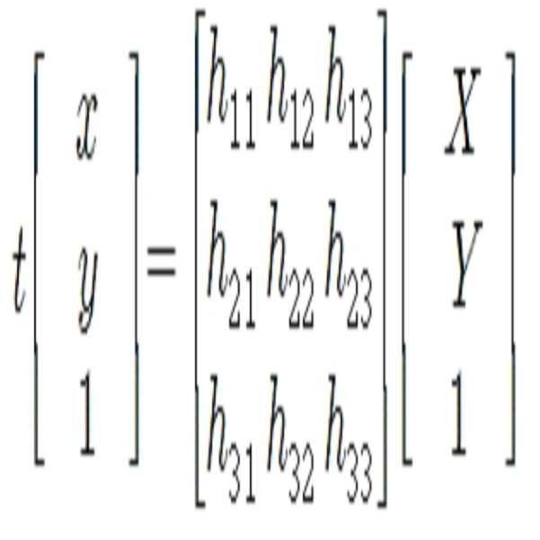
상기 수학식 1에서 t는 기 설정되는 0이 아닌 상수, X, Y는 제 1 영역(15) 내 기 설정된 위치의 제 1 좌표 정보, x, y는 제 2 영역(25) 내 기 설정된 위치의 제 2 좌표 정보 및 h11 내지 h33은 상기 좌표 변환(H)의 행렬 요소를 나타낸다.Where x and y are first coordinate information of a predetermined position in the
상기 수학식 1은 아래의 수학식 2 내지 수학식 4로 변형될 수 있다.The above equation (1) can be transformed into the following equations (2) to (4).
[수학식 2]&Quot; (2) "

[수학식 3]&Quot; (3) "

[수학식 4]&Quot; (4) "

상기 수학식 4는 수학식 3을 푼 후, 좌표 변환(H)의 행렬 요소들(h11 내지 h33)을 열 행렬로 변형한 것이다.Equation (4) is obtained by transforming the matrix elements (h11 to h33) of the coordinate transformation (H) into a column matrix after solving Equation (3).
상기 수학식 4에서 행렬 요소들(h11 내지 h33)의 열 행렬(h) 중 행렬 요소 h33은 1로 정규화되기 때문에 결국 8개의 행렬 요소만을 산출하면 되므로, 8개의 행렬 요소의 산출을 위해서는 적어도 4개의 좌표 정보쌍(즉, 4개의 제 1 좌표 정보와 그에 대응하는 4개의 제 2 좌표 정보)이 필요하다.Since the matrix element h33 of the column matrix h of the matrix elements h11 to h33 in Equation (4) is normalized to 1, only eight matrix elements are calculated. Therefore, in order to calculate eight matrix elements, at least four A pair of coordinate information (i.e., four pieces of first coordinate information and four pieces of second coordinate information corresponding thereto) are required.
4개의 정보쌍을 상기 수학식 4에 대입하면 아래의 수학식 5와 같이 표현될 수 있다.Substituting the four pairs of information into Equation (4), Equation (5) can be expressed as Equation (5).
[수학식 5]&Quot; (5) "

상기 수학식 5에서, X1, Y1, x1, y1은 제 1 영역(15)과 제 2 영역(25) 내 서로 동일한 위치(예를 들어, 도 3의 A1 지점과 A2 지점)에 대한 제 1 좌표 정보와 제 2 좌표 정보, X2, Y2, x2, y2은 제 1 영역(15)과 제 2 영역(25) 내 서로 동일한 위치(예를 들어, 도 3의 B1 지점과 B2 지점)에 대한 제 1 좌표 정보와 제 2 좌표 정보, X3, Y3, x3, y3은 제 1 영역(15)과 제 2 영역(25) 내 서로 동일한 위치(예를 들어, 도 3의 C1 지점과 C2 지점)에 대한 제 1 좌표 정보와 제 2 좌표 정보, X4, Y4, x4, y4은 제 1 영역(15)과 제 2 영역(25) 내 서로 동일한 위치(예를 들어, 도 3의 D1 지점과 D2 지점)에 대한 제 1 좌표 정보와 제 2 좌표 정보를 나타낸다.X1, Y1, x1 and y1 in the above equation (5) are the same as the first coordinates (X1, Y1, X1, (For example, the points B1 and B2 in FIG. 3) in the
좌표 변환(H)를 열 행렬(h)로 변경하였을 때, A를 특이 값 분해 (Singular Value Decomposition; SVD)함으로써, 열 행렬(h)을 산출할 수 있다.When the coordinate transformation H is changed to the column matrix h, the column matrix h can be calculated by performing A singular value decomposition (SVD).
A를 특이 값 분해하면, 아래의 수학식 6과 같이 나타낼 수 있다.If A is singular value decomposed, it can be expressed by the following Equation (6).
[수학식 6]&Quot; (6) "
![]()
![]()
특이 값 분해 후, 수학식 6의 V 행렬의 마지막 열 행렬을 열 행렬(h)로 결정할 수 있다. 열 행렬(h)이 도출되면, 영역 감시 장치(100)는 열 행렬(h)을 통해 좌표 변환(H)를 결정할 수 있다.After the singular value decomposition, the last column matrix of the V matrix of Equation (6) can be determined as a column matrix (h). Once the column matrix h is derived, the
다시 도 2를 보면, S240 단계에서, 영역 감시 장치(100)는 레이더(10)의 검출 정보에서 소정 오브젝트에 대한 추적 정보를 추출하고, 카메라(20) 영상 내 소정 오브젝트에 상기 추적 정보에 대응하는 식별 마크를 표시한다.Referring again to FIG. 2, in step S240, the
영역 감시 장치(100)는 식별 마크가 표시된 카메라 영상을 디스플레이하여 운영자로 하여금 사고가 발생하였는지, 어느 곳에서 사고가 발생하였는지의 정보 등을 정확하게 알려줄 수 있다.The
도 4(a)는 레이더(10)에 의해 획득되는 검출 정보를 도시하는 예시적인 도면이고, 도 4(b)는 식별 마크가 표시된 카메라 영상을 도시하는 예시적인 도면이다.Fig. 4 (a) is an exemplary diagram showing detection information obtained by the
도 4(a)를 참조하면, 검출 정보(410)는 제 1 영역(15)에 위치하는 오브젝트들의 추적 정보(412a, 412b, 412c, 412d)를 포함할 수 있다. 도 4(a)에서는 추적 정보를 식별 마크(412a, 412b, 412c, 412d)로 도시하고 있는데, 이는 하나의 예시일 뿐이며, 레이더(10)는 추적 정보를 도 4(a)와 같은 영상 형태가 아닌 텍스트 형태로 제공할 수도 있다.Referring to FIG. 4A, the
영역 감시 장치(100)는 도 4(a)에 도시된 추적 정보(412a, 412b, 412c, 412d)로부터 각 오브젝트의 좌표 정보를 추출하고, 이를 좌표 변환(H)에 적용하여 영상(430)에서의 각 오브젝트의 좌표 정보를 추출한다. The
그리고, 영역 감시 장치(100)는 도 4(b)에 도시된 바와 같이, 추적 정보(412a, 412b, 412c, 412d)에 대응하는 식별 마크들(434a, 434b, 434c)을 영상(430) 내 오브젝트(432a, 432b, 432c)에 표시할 수 있다.4 (b), the
예를 들어, 영역 감시 장치(100)는 추적 정보(412a, 412b, 412c, 412d)로부터 획득되는 측정 값들(예를 들어, 속도, 가속도 및 감속도 중 적어도 하나)과 소정 기준 값을 비교한 후, 비교 결과에 맞는 형상 및/또는 컬러를 갖는 식별 마크를 영상(430)에 표시할 수 있다. 구체적으로, 감속도가 제 1 기준 값을 초과하는 경우에는 제 1 형상 및/또는 제 1 컬러의 식별 마크를 대응 오브젝트에 표시하고, 감속도가 제 1 기준 값 이하 및 제 2 기준 값을 초과하는 값을 갖는 경우에는 제 2 형상 및/또는 제 2 컬러의 식별 마크를 대응 오브젝트에 표시하고, 감속도가 제 2 기준 값 이하인 경우에는 제 3 형상 및/또는 제 3 컬러의 식별 마크를 대응 오브젝트에 표시할 수 있다.For example, the
영역 감시 장치(100)는 식별 마크들(434a, 434b, 434c)이 표시된 영상(430)을 디스플레이함으로써, 운영자는 식별 마크(434a, 434b, 434c)를 통해 사고 발생 여부를 알 수 있고, 또한, 실제 촬영되는 영상(430)을 통해 어디에서 사고가 발생하였는지, 실제 사고가 발생한 것인지를 알 수 있게 된다.The
도 5는 본 발명의 일 실시예에 따른 영역 감시 장치(100)의 블록도이다.5 is a block diagram of an
도 5를 참조하면, 본 발명의 일 실시예에 따른 영역 감시 장치(100)는 통신부(610), 제어부(630), 이미지 처리부(650) 및 디스플레이(670)를 포함할 수 있다. 통신부(610), 제어부(630) 및 이미지 처리부(650)는 적어도 하나의 프로세서로 구현될 수 있으며, 메모리(미도시)에 저장된 프로그램에 따라 동작할 수 있다.5, the
통신부(610)는 레이더(10)에 의해 검출되는 제 1 영역(15)의 검출 정보를 레이더(10) 또는 기타 외부 서버로부터 수신하고, 카메라(20)에 의해 촬영되는 제 2 영역의 영상을 카메라(20) 또는 기타 외부 서버로부터 수신한다.The
제어부(630)는 제 1 영역(15) 내 기 설정된 위치의 제 1 좌표 정보와 제 2 영역 내 기 설정된 위치의 제 2 좌표 정보를 이용하여 레이더(10)의 기준 좌표와 카메라(20)의 기준 좌표 사이의 좌표 변환을 획득한다. 좌표 변환을 획득하는 방법에 대해서는 상술하였는바, 상세한 설명은 생략한다.The
이미지 처리부(650)는 검출 정보에서 소정 오브젝트에 대한 추적 정보를 추출하고, 제 2 영역의 영상의 소정 오브젝트에 상기 추적 정보에 대응하는 식별 마크를 표시한다.The
디스플레이(670)는 식별 마크가 표시된 영상을 디스플레이한다.The
또한, 구현예에 따라서는 영역 감시 장치(100)는 레이더(10)에서 검출되는 검출 정보로부터 사고가 발생한 것으로 예측되는 경우(예를 들어, 오브젝트의 감속도가 기준 값을 초과한 경우) 디스플레이(670) 또는 스피커를 통해 알람을 발생시켜 운영자의 주의를 환기시킬 수도 있다.According to an embodiment, when the
한편, 상술한 본 발명의 실시예들은 컴퓨터에서 실행될 수 있는 프로그램으로 작성가능하고, 작성된 프로그램은 매체에 저장될 수 있다.Meanwhile, the embodiments of the present invention described above can be written in a program that can be executed in a computer, and the created program can be stored in a medium.
상기 매체는 마그네틱 저장매체(예를 들면, 롬, 플로피 디스크, 하드디스크 등), 광학적 판독 매체(예를 들면, 시디롬, 디브이디 등)와 같은 저장매체를 포함할 수 있으나, 이에 한정되는 것은 아니다.The medium may include, but is not limited to, storage media such as magnetic storage media (e.g., ROM, floppy disks, hard disks, etc.), optical reading media (e.g., CD ROMs,
첨부된 도면을 참조하여 본 발명의 실시예를 설명하였지만, 본 발명이 속하는 기술분야에서 통상의 지식을 가진 자는 본 발명이 그 기술적 사상이나 필수적인 특징을 변경하지 않고서 다른 구체적인 형태로 실시될 수 있다는 것을 이해할 수 있을 것이다. 그러므로 이상에서 기술한 실시예들은 모든 면에서 예시적인 것이며 한정적이 아닌 것으로 이해해야만 한다.It will be understood by those skilled in the art that various changes in form and details may be made therein without departing from the spirit and scope of the present invention as defined by the following claims. You will understand. It is therefore to be understood that the above-described embodiments are illustrative in all aspects and not restrictive.
100: 영역 감시 장치
10: 레이더
20, 20a, 20b; 카메라
30, 432a, 432b, 432c: 오브젝트
610: 통신부
630: 제어부
650: 이미지 처리부
670: 디스플레이100: Area monitoring device
10: Radar
20, 20a, 20b; camera
30, 432a, 432b, 432c: object
610:
630:
650:
670: Display
Claims (5)
카메라에 의해 촬영되는 제 2 영역의 영상을 획득하는 단계;
상기 제 1 영역 내 기 설정된 위치의 좌표 정보와 상기 제 2 영역 내 기 설정된 위치의 좌표 정보를 이용하여 상기 레이더의 기준 좌표와 상기 카메라의 기준 좌표 사이의 좌표 변환을 획득하는 단계; 및
상기 검출 정보에서 소정 오브젝트에 대한 추적 정보를 추출하고, 상기 영상 소정 오브젝트에 상기 추적 정보에 대응하는 식별 마크를 표시하는 단계를 포함하는 것을 특징으로 하는, 영역 감시 장치에 의한 영역 감시 방법.
Obtaining detection information of a first area detected by a radar;
Obtaining an image of a second region photographed by a camera;
Acquiring coordinate transformation between the reference coordinates of the radar and the reference coordinates of the camera using the coordinate information of the predetermined position in the first area and the coordinate information of the predetermined position in the second area; And
Extracting tracking information on a predetermined object from the detection information, and displaying an identification mark corresponding to the tracking information on the image predetermined object.
상기 제 1 영역 내 기 설정된 위치와 상기 제 2 영역 내 기 설정된 위치 각각은 적어도 4개를 포함하는 것을 특징으로 하는 영역 감시 방법.
The method according to claim 1,
Wherein the predetermined area in the first area and the predetermined area in the second area each include at least four areas.
상기 좌표 변환을 획득하는 단계는,
상기 제 1 영역 내 적어도 4개의 기 설정된 위치와 상기 제 2 영역 내 적어도 4개의 기 설정된 위치 각각의 좌표 정보쌍 각각을 하기의 수학식에 적용하여 상기 좌표 변환을 획득하되,
[수학식]

상기 수학식에서 t는 기 설정되는 0이 아닌 상수, X, Y는 제 1 영역 내 기 설정된 위치의 좌표 정보, x, y는 제 2 영역 내 기 설정된 위치의 좌표 정보 및 h11 내지 h33은 상기 좌표 변환의 행렬 요소를 나타내는 것을 특징으로 하는 영역 감시 방법.
3. The method of claim 2,
Wherein obtaining the coordinate transformation comprises:
Obtaining coordinate transformation by applying each of coordinate information pairs of at least four preset positions in the first area and at least four predetermined positions in the second area to the following equation,
[Mathematical Expression]
Where x and y are coordinate information of a predetermined position in the first area, x and y are coordinate information of a predetermined position in the second area, and h 11 to h 33 are coordinate information of a predetermined position in the second area, And a matrix element of the coordinate transformation.
상기 추적 정보는 상기 소정 오브젝트의 위치 정보, 속도 정보, 가속도 정보 및 감속도 정보 중 적어도 하나를 포함하되,
상기 식별 마크를 표시하는 단계는,
상기 추적 정보와 기 설정된 기준 값을 비교하여, 비교 결과에 대응하는 형상 및/또는 컬러의 상기 식별 마크를 상기 영상에 표시하는 단계를 포함하는 것을 특징으로 하는 영역 감시 방법.
The method according to claim 1,
Wherein the tracking information includes at least one of position information, velocity information, acceleration information, and deceleration information of the predetermined object,
Wherein the step of displaying the identification mark comprises:
Comparing the tracking information with a predetermined reference value, and displaying the identification mark of the shape and / or color corresponding to the comparison result on the image.
상기 제 1 영역 내 기 설정된 위치의 좌표 정보와 상기 제 2 영역 내 기 설정된 위치의 좌표 정보를 이용하여 상기 레이더의 기준 좌표와 상기 카메라의 기준 좌표 사이의 좌표 변환을 획득하는 제어부; 및
상기 검출 정보에서 소정 오브젝트에 대한 추적 정보를 추출하고, 상기 제 2 영역의 영상의 소정 오브젝트에 상기 추적 정보에 대응하는 식별 마크를 표시하는 이미지 처리부를 포함하는 것을 특징으로 하는 영역 감시 장치.
A communication unit for acquiring detection information of a first area detected by the radar and acquiring an image of a second area photographed by the camera;
A controller for obtaining a coordinate transformation between the reference coordinates of the radar and the reference coordinates of the camera using the coordinate information of the predetermined region in the first region and the coordinate information of the predetermined region in the second region; And
And an image processing unit for extracting tracking information on a predetermined object from the detection information and displaying an identification mark corresponding to the tracking information on a predetermined object of the image of the second area.
Priority Applications (1)
| Application Number | Priority Date | Filing Date | Title |
|---|---|---|---|
| KR1020170052974A KR20180119344A (en) | 2017-04-25 | 2017-04-25 | Region monitoring apparatus and method for monitoring region thereby |
Applications Claiming Priority (1)
| Application Number | Priority Date | Filing Date | Title |
|---|---|---|---|
| KR1020170052974A KR20180119344A (en) | 2017-04-25 | 2017-04-25 | Region monitoring apparatus and method for monitoring region thereby |
Publications (1)
| Publication Number | Publication Date |
|---|---|
| KR20180119344A true KR20180119344A (en) | 2018-11-02 |
Family
ID=64328559
Family Applications (1)
| Application Number | Title | Priority Date | Filing Date |
|---|---|---|---|
| KR1020170052974A KR20180119344A (en) | 2017-04-25 | 2017-04-25 | Region monitoring apparatus and method for monitoring region thereby |
Country Status (1)
| Country | Link |
|---|---|
| KR (1) | KR20180119344A (en) |
Cited By (2)
| Publication number | Priority date | Publication date | Assignee | Title |
|---|---|---|---|---|
| WO2020108647A1 (en) * | 2018-11-30 | 2020-06-04 | 杭州海康威视数字技术股份有限公司 | Target detection method, apparatus and system based on linkage between vehicle-mounted camera and vehicle-mounted radar |
| US20220317238A1 (en) * | 2019-02-01 | 2022-10-06 | Nec Corporation | Vessel analysis device, vessel behavior learning device, vessel analysis system, vessel analysis method, vessel behavior learning method, and recording medium |
-
2017
- 2017-04-25 KR KR1020170052974A patent/KR20180119344A/en not_active Application Discontinuation
Cited By (2)
| Publication number | Priority date | Publication date | Assignee | Title |
|---|---|---|---|---|
| WO2020108647A1 (en) * | 2018-11-30 | 2020-06-04 | 杭州海康威视数字技术股份有限公司 | Target detection method, apparatus and system based on linkage between vehicle-mounted camera and vehicle-mounted radar |
| US20220317238A1 (en) * | 2019-02-01 | 2022-10-06 | Nec Corporation | Vessel analysis device, vessel behavior learning device, vessel analysis system, vessel analysis method, vessel behavior learning method, and recording medium |
Similar Documents
| Publication | Publication Date | Title |
|---|---|---|
| EP3620926B1 (en) | Method and apparatus for testing autonomous vehicle, and storage medium | |
| KR101622028B1 (en) | Apparatus and Method for controlling Vehicle using Vehicle Communication | |
| KR101727162B1 (en) | Apparatus and method for providing vessel traffic service | |
| US7218757B2 (en) | Method and device for detecting obstruction in image sensor systems | |
| US20090058622A1 (en) | Method for predicting lane line and lane departure warning system using the same | |
| KR102158497B1 (en) | evaluation system for autonomous driving | |
| US10516855B2 (en) | Monitoring system, monitoring method, and monitoring program | |
| CN112014845A (en) | Vehicle obstacle positioning method, device, equipment and storage medium | |
| CN110610137B (en) | Method and device for detecting vehicle running state, electronic equipment and storage medium | |
| KR20180131033A (en) | Calibration apparatus and method of camera and rader | |
| US11798291B2 (en) | Redundancy information for object interface for highly and fully automated driving | |
| JP5820135B2 (en) | Logistics quality inspection method, data processing apparatus, data recorder, and computer program | |
| CN110174706B (en) | Object monitoring device using sensor | |
| CN104167109A (en) | Detection method and detection apparatus for vehicle position | |
| WO2022205106A1 (en) | Early warning method and apparatus for vehicle, and device and storage medium | |
| KR20130140331A (en) | Apparatus and method for managing vehicle accident | |
| JP2009159448A (en) | Object detecting apparatus, and object detecting method | |
| KR20180119344A (en) | Region monitoring apparatus and method for monitoring region thereby | |
| JP6610994B2 (en) | Obstacle detection device and obstacle detection method | |
| JP4176558B2 (en) | Vehicle periphery display device | |
| CN110745145A (en) | Multi-sensor management system for ADAS | |
| KR20130037902A (en) | System and method for alarming and monitoring dangerous situations using multi-sensor | |
| JPWO2019131388A1 (en) | Driving support device, driving support system, driving support method, and driving support program | |
| CN112633143B (en) | Image processing system, method, head-mounted device, processing device, and storage medium | |
| JP5959682B2 (en) | System and method for calculating the distance between an object and a vehicle |
Legal Events
| Date | Code | Title | Description |
|---|---|---|---|
| A201 | Request for examination | ||
| E902 | Notification of reason for refusal | ||
| AMND | Amendment | ||
| E902 | Notification of reason for refusal | ||
| AMND | Amendment | ||
| E601 | Decision to refuse application | ||
| X091 | Application refused [patent] | ||
| E601 | Decision to refuse application | ||
| E801 | Decision on dismissal of amendment |