KR20180104254A - Cooling Tower Reducing Generation of White Plume - Google Patents
Cooling Tower Reducing Generation of White Plume Download PDFInfo
- Publication number
- KR20180104254A KR20180104254A KR1020170030802A KR20170030802A KR20180104254A KR 20180104254 A KR20180104254 A KR 20180104254A KR 1020170030802 A KR1020170030802 A KR 1020170030802A KR 20170030802 A KR20170030802 A KR 20170030802A KR 20180104254 A KR20180104254 A KR 20180104254A
- Authority
- KR
- South Korea
- Prior art keywords
- air
- filter
- unit
- filter module
- housing
- Prior art date
Links
Images


Classifications
-
- F—MECHANICAL ENGINEERING; LIGHTING; HEATING; WEAPONS; BLASTING
- F28—HEAT EXCHANGE IN GENERAL
- F28C—HEAT-EXCHANGE APPARATUS, NOT PROVIDED FOR IN ANOTHER SUBCLASS, IN WHICH THE HEAT-EXCHANGE MEDIA COME INTO DIRECT CONTACT WITHOUT CHEMICAL INTERACTION
- F28C1/00—Direct-contact trickle coolers, e.g. cooling towers
- F28C1/16—Arrangements for preventing condensation, precipitation or mist formation, outside the cooler
-
- C—CHEMISTRY; METALLURGY
- C09—DYES; PAINTS; POLISHES; NATURAL RESINS; ADHESIVES; COMPOSITIONS NOT OTHERWISE PROVIDED FOR; APPLICATIONS OF MATERIALS NOT OTHERWISE PROVIDED FOR
- C09D—COATING COMPOSITIONS, e.g. PAINTS, VARNISHES OR LACQUERS; FILLING PASTES; CHEMICAL PAINT OR INK REMOVERS; INKS; CORRECTING FLUIDS; WOODSTAINS; PASTES OR SOLIDS FOR COLOURING OR PRINTING; USE OF MATERIALS THEREFOR
- C09D143/00—Coating compositions based on homopolymers or copolymers of compounds having one or more unsaturated aliphatic radicals, each having only one carbon-to-carbon double bond, and containing boron, silicon, phosphorus, selenium, tellurium, or a metal; Coating compositions based on derivatives of such polymers
- C09D143/02—Homopolymers or copolymers of monomers containing phosphorus
-
- C—CHEMISTRY; METALLURGY
- C09—DYES; PAINTS; POLISHES; NATURAL RESINS; ADHESIVES; COMPOSITIONS NOT OTHERWISE PROVIDED FOR; APPLICATIONS OF MATERIALS NOT OTHERWISE PROVIDED FOR
- C09D—COATING COMPOSITIONS, e.g. PAINTS, VARNISHES OR LACQUERS; FILLING PASTES; CHEMICAL PAINT OR INK REMOVERS; INKS; CORRECTING FLUIDS; WOODSTAINS; PASTES OR SOLIDS FOR COLOURING OR PRINTING; USE OF MATERIALS THEREFOR
- C09D143/00—Coating compositions based on homopolymers or copolymers of compounds having one or more unsaturated aliphatic radicals, each having only one carbon-to-carbon double bond, and containing boron, silicon, phosphorus, selenium, tellurium, or a metal; Coating compositions based on derivatives of such polymers
- C09D143/04—Homopolymers or copolymers of monomers containing silicon
-
- F—MECHANICAL ENGINEERING; LIGHTING; HEATING; WEAPONS; BLASTING
- F28—HEAT EXCHANGE IN GENERAL
- F28F—DETAILS OF HEAT-EXCHANGE AND HEAT-TRANSFER APPARATUS, OF GENERAL APPLICATION
- F28F19/00—Preventing the formation of deposits or corrosion, e.g. by using filters or scrapers
- F28F19/02—Preventing the formation of deposits or corrosion, e.g. by using filters or scrapers by using coatings, e.g. vitreous or enamel coatings
-
- F—MECHANICAL ENGINEERING; LIGHTING; HEATING; WEAPONS; BLASTING
- F28—HEAT EXCHANGE IN GENERAL
- F28F—DETAILS OF HEAT-EXCHANGE AND HEAT-TRANSFER APPARATUS, OF GENERAL APPLICATION
- F28F25/00—Component parts of trickle coolers
- F28F25/02—Component parts of trickle coolers for distributing, circulating, and accumulating liquid
- F28F25/04—Distributing or accumulator troughs
-
- F—MECHANICAL ENGINEERING; LIGHTING; HEATING; WEAPONS; BLASTING
- F28—HEAT EXCHANGE IN GENERAL
- F28F—DETAILS OF HEAT-EXCHANGE AND HEAT-TRANSFER APPARATUS, OF GENERAL APPLICATION
- F28F2245/00—Coatings; Surface treatments
- F28F2245/04—Coatings; Surface treatments hydrophobic
Landscapes
- Engineering & Computer Science (AREA)
- Chemical & Material Sciences (AREA)
- Mechanical Engineering (AREA)
- General Engineering & Computer Science (AREA)
- Life Sciences & Earth Sciences (AREA)
- Materials Engineering (AREA)
- Wood Science & Technology (AREA)
- Organic Chemistry (AREA)
- Physics & Mathematics (AREA)
- Thermal Sciences (AREA)
- Filtering Materials (AREA)
Abstract
Description
본 발명은 백연 발생 저감 쿨링 타워에 관한 것이다.The present invention relates to a cooling tower for reducing white smoke.
기존의 쿨링 타워는 개방형으로 형성되며, 개방된 하우징의 내부로 사용된 냉각수를 분사하고 외부 공기를 유입시켜 냉각수를 냉각시키는 방식을 사용하고 있다. 보다 구체적으로는 쿨링 타워는 사용된 냉각수를 하우징의 내부 공간으로 분사하고 외부 공기를 유입시켜 냉각수와 접촉시켜 냉각수를 냉각시키며, 수증기를 포함하는 배출 공기를 다시 외부로 배출한다. 따라서, 상기 쿨링 타워는 수증기를 포함하는 포화 공기를 가열하여 외부로 배출하게 되므로, 배출되는 배출 공기가 상대적으로 낮은 온도의 차가운 외부 공기와 만나면서 수증기가 응결되어 백연을 발생시킨다. 상기 백연은 수증기외에 유해 물질을 포함하고 있지 않으나, 외관상으로는 유해한 것으로 인식될 수 있어 주위 환경 및 주거지 환경에 영향을 미치게 된다. 최근에는 백연을 제거하기 위하여 배출 공기를 냉각시켜 외부로 배출 시키는 방법등이 검토하고 있으나, 효과적이지 못한 것으로 평가되고 있다. 따라서, 상기 백연을 제거하기 위한 기술 개발이 필요한 실정이다.The conventional cooling tower is formed as an open type, and uses a method of injecting cooling water used as an inside of the opened housing and cooling the cooling water by introducing outside air. More specifically, the cooling tower injects the used cooling water into the inner space of the housing, introduces outside air to cool the cooling water by bringing the cooling water into contact with the cooling water, and discharges the exhaust air containing the steam back to the outside. Therefore, the cooling tower heats the saturated air containing steam and discharges it to the outside, so that the discharged air coincides with the cold outside air at a relatively low temperature, and the water vapor condenses to generate white smoke. The white smoke does not contain harmful substances other than water vapor, but it can be perceived to be harmful in appearance, which affects the surrounding environment and the residential environment. Recently, a method of cooling the exhaust air and discharging it to the outside in order to remove the white smoke has been considered, but it is considered to be ineffective. Therefore, it is necessary to develop a technique for removing the white smoke.
최근에, 쿨링 타워의 외부로 배출되는 배출 공기의 온도를 더 높이기 위한 가열 수단이나 배출 공기에 포함되어 있는 수증기를 포집하기 위한 필터링 수단을 쿨링 타워의 내부에 설치하여 백연을 감소시키고자 하는 시도가 진행되고 있다. 그러나, 상기 쿨링 타워의 내부에 가열 수단이나 필터링 수단을 설치하는 경우에 수증기를 포함하는 공기가 원활하게 배출되지 못하는 측면이 있다. 특히, 쿨링 타워 내부에 차압이 발생하므로 냉각 팬의 용량을 증가시키거나 내부 용적을 증가시켜야 하는 측면이 있다.In recent years, an attempt has been made to reduce the white smoke by providing heating means for further increasing the temperature of the exhaust air discharged to the outside of the cooling tower or filtering means for trapping the water vapor contained in the exhaust air, inside the cooling tower It is progressing. However, in the case where the heating means or the filtering means is provided inside the cooling tower, there is a side where the air including steam is not smoothly discharged. Particularly, since a differential pressure is generated inside the cooling tower, the capacity of the cooling fan must be increased or the internal volume thereof must be increased.
본 발명의 목적은 쿨링 타워의 내부에 차압이 유발되지 않도록 백연 발생의 원인이 되는 수증기 미스트를 효과적으로 포집할 수 있는 백연 발생 저감 쿨링 타워를 제공하는데 있다.SUMMARY OF THE INVENTION It is an object of the present invention to provide a cooling tower capable of effectively collecting steam mist which is a cause of occurrence of white smoke so that a differential pressure is not generated inside the cooling tower.
본 발명에 따른 백연 발생 저감 쿨링 타워는 내부가 중공인 통 형상으로 형성되며, 외부 공기가 유입되는 공기 유입구와 배출 공기가 배출되는 공기 배출구를 구비하는 하우징과, 상기 하우징의 내부에서 상기 공기 유입구의 상부에 위치되며, 사용된 냉각수를 상기 하우징의 내부로 분사하는 노즐 유닛과, 상기 하우징의 공기 배출구에 결합되는 배출관을 포함하며, 상기 하우징 내부의 공기를 상기 하우징의 상부로 배출하는 배출 유닛 및 상기 하우징의 상부에서 상기 배출관의 상부와 측부를 감싸도록 위치하며, 상기 배출 유닛으로부터 배출되는 포화 공기에 포함되어 있는 수증기 미스트를 포집하는 단위 필터 모듈을 적어도 1 개를 포함하는 수증기 필터 유닛을 포함하는 것을 특징으로 한다.The cooling tower of the present invention comprises a housing having a hollow interior and having an air inlet through which outside air is introduced and an air outlet through which exhaust air is discharged; And a discharge unit coupled to the air discharge port of the housing, the discharge unit discharging the air inside the housing to the upper portion of the housing, And a water filter unit disposed at an upper portion of the housing to surround the upper and side portions of the discharge pipe and at least one unit filter module for collecting steam mist contained in the saturated air discharged from the discharge unit .
또한, 상기 단위 필터 모듈은 서로 이격되는 수증기 필터 및 상기 수증기 필터 사이에 위치하여 일측의 상기 수증기 필터를 통과하는 포화 공기를 냉각 또는 가열하는 온도 조절 수단을 포함하여 형성될 수 있다.The unit filter module may include a water vapor filter spaced apart from each other and a temperature adjusting unit positioned between the water vapor filter and cooling or heating the saturated air passing through the water vapor filter at one side.
또한, 상기 온도 조절 수단은 내부가 중공인 금속관이 서로 이격되면서 지그재그 형상으로 연장되어 판상 형상을 이루도록 형성되며, 내부에 냉각수, 냉매, 냉각된 공기, 온수 또는 가열된 공기가 흐르는 에바 및 상기 에바의 외측을 감싸도록 지지하는 지지 프레임을 포함하여 형성될 수 있다.In addition, the temperature adjusting means is formed to have a plate-like shape extending in a zigzag shape while being spaced apart from each other by hollow metallic tubes, and is provided with a cooler, refrigerant, cooled air, hot water, And a support frame for supporting the outer periphery.
또한, 상기 온도 조절 수단은 링 형상으로 형성되며, 서로 인접하는 수증기 필터 사이에 위치하여 상기 수증기 필터 사이에 공기 분사 공간을 형성하는 온도 조절 프레임 및 상기 온도 조절 프레임의 일측변에서 상기 공기 분사 공간으로 관통되어 상기 공기 분사 공간으로 공기를 분사하는 공기 분사관을 포함하여 형성될 수 있다. 이때, 상기 공기 분사관은 하나의 관으로 형성되는 메인 공급관 및 복수 개로 형성되고 일측이 모두 메인 공급관에 연결되며, 타측이 상기 온도 조절 프레임의 일측변에 서로 이격되어 연결되는 분기관을 포함하여 형성될 수 있다. 또한, 상기 공기 분사관은 하나의 관으로 형성되는 메인 공급관 및 일측이 메인 공급관에 연결되며, 일측에서 타측으로 갈수록 폭이 증가되어 타측이 상기 온도 조절 프레임의 일측변을 관통하여 상기 공기 분사 공간에 연결될 수 있다.The temperature regulating means may include a temperature regulating frame formed in a ring shape and positioned between the water vapor filters adjacent to each other to form an air injection space between the water vapor filters, And an air spraying pipe for spraying air into the air injection space. At this time, the air injection pipe includes a main supply pipe formed by one pipe and a branch pipe formed by a plurality of pipes, one side of which is connected to the main supply pipe and the other side of which is connected to one side of the temperature regulation frame . The air injection pipe is connected to the main supply pipe and one side of the air supply pipe is connected to the main supply pipe. The width of the air supply pipe increases from one side to the other side, and the other side passes through one side of the temperature regulation frame, Can be connected.
또한, 상기 수증기 필터 유닛은 적어도 1 개의 상기 단위 필터 모듈을 포함하고, 상기 배출관의 상부에 이격되어 상부 필터 모듈 및 적어도 1 개의 상기 단위 필터 모듈을 포함하고, 상기 배출과의 측부에 이격되어 위치하는 측부 필터 모듈을 포함하여 형성될 수 있다.Also, the steam filter unit includes at least one unit filter module, the upper filter module and the at least one unit filter module being spaced apart from the upper portion of the discharge pipe, And a side filter module.
또한, 상기 상부 필터 모듈은 전체 면적이 상기 배출관의 상단부 면적보다 큰 면적이 되도록 복수 개의 상기 단위 필터 모듈이 판상으로 조립되어 형성되며, 상기 측부 필터 모듈은 상기 배출관을 형성하는 측벽의 개수에 대응되는 개수로 형성되며, 각각 상기 배출관의 측벽의 면적보다 큰 면적이 되도록 복수 개의 상기 단위 필터 모듈이 판상으로 조립되어 상기 배출관의 각 측벽과 평행하도록 수직 방향으로 위치하도록 형성될 수 있다.The plurality of unit filter modules are assembled in a plate shape so that the total area of the upper filter module is larger than the upper end area of the discharge pipe. A plurality of the unit filter modules are assembled in a plate shape so as to be located in a vertical direction so as to be parallel to the side walls of the discharge pipe.
또한, 상기 상부 필터 모듈은 상기 단위 필터 모듈이 수직 방향으로 이격되면서 적어도 2 층으로 적층되어 형성되며, 상기 측부 필터 모듈은 상기 단위 필터 모듈이 수평 방향으로 이격되면서 적어도 2 층으로 형성될 수 있다.In addition, the upper filter module may be formed by stacking at least two layers while the unit filter modules are vertically spaced apart, and the side filter module may be formed of at least two layers while the unit filter modules are horizontally spaced apart.
또한, 상기 상부 필터 모듈의 상부에 위치하여 상기 상부 필터 모듈의 상부로 바람을 공급하는 적어도 1개의 송풍 수단을 구비하는 상부 송풍 모듈 및 상기 기 측부 필터 모듈의 외측에 위치하여 바람을 공급하는 적어도 1 개의 상기 송풍 수단을 구비하는 측부 송풍 모듈을 더 포함하여 형성될 수 있다. 이때, 상기 송풍 수단은 송풍 팬 또는 에어 노즐로 형성될 수 있다.The upper filter module may include an upper blower module disposed at an upper portion of the upper filter module to supply wind to the upper portion of the upper filter module and at least one blower module disposed at an upper portion of the upper filter module, And a side air blowing module including the air blowing means. At this time, the blowing means may be formed of a blowing fan or an air nozzle.
또한, 상기 수증기 필터는 외면에서 내부로 연결되는 다수의 기공을 포함하는 기본 구조체 및 상기 기본 구조체의 표면에 코팅되는 표면층을 구비하며, 상기 표면층은 CF(탄화불소)기 또는 CH(탄화수소)기를 포함하는 하기의 구조식(1)으로 표시되는 실란계 화합물을 포함할 수 있다.The surface layer may include a CF (fluorocarbon) group or a CH (hydrocarbon) group. The surface layer may include a CF (fluorocarbon) group or a CH (hydrocarbon) group. Containing silane compound represented by the following structural formula (1).
구조식(1)The structural formula (1)


(여기서, n은 4 ~ 25이다.)(Where n is 4 to 25).
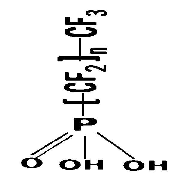
또한, 상기 표면층은 CF(탄화불소)기 또는 CH(탄화수소)기를 포함하는 하기의 구조식(2)으로 표시되는 인산계 화합물을 포함하여 형성될 수 있다.Further, the surface layer may be formed of a phosphate compound represented by the following structural formula (2) containing a CF (fluorocarbon) group or a CH (hydrocarbon) group.
구조식(2)Structural formula (2)


또한, 상기 표면층은 HDF-S, OD-PA 또는 HDF-PA로 형성될 수 있다.In addition, the surface layer may be formed of HDF-S, OD-PA or HDF-PA.
또한, 상기 기본 구조체는 니켈, 알루미늄, 스테인레스 스틸, 모넬, 인코넬, 텅스텐, 은 티타늄, 몰리브덴, 듀플렉스, 구리, 철, 폴리에스테르, 나일론, 폴리에틸렌, 폴리프로필렌 또는 화이버 글라스로 형성될 수 있다.The base structure may be formed of nickel, aluminum, stainless steel, monel, inconel, tungsten, silver titanium, molybdenum, duplex, copper, iron, polyester, nylon, polyethylene, polypropylene or fiberglass.
또한, 상기 기본 구조체는 5㎛ ~ 1000㎛의 기공 크기를 가지도록 형성될 수 있다.Also, the basic structure may be formed to have a pore size of 5 mu m to 1000 mu m.
또한, 상기 기본 구조체는 2차원 메쉬 형상 또는 2차원 그물망 형상, 상기 2차원 메쉬 형상이 적층되어 형성되는 3차원 메쉬 형상, 3차원 다공성 폼 형상, 3차원 망상 구조 또는 3차원 네트워크 구조로 형성되는 3차원 구조체로 형성될 수 있다.In addition, the basic structure may include a three-dimensional mesh shape, a three-dimensional mesh shape, a three-dimensional mesh shape, a three-dimensional mesh structure, or a three-dimensional network structure formed by stacking the two- Dimensional structure.
또한, 상기 수증기 필터는 상기 기본 구조체와 상기 표면층의 사이에 형성되는 계면층을 더 포함하여 형성될 수 있다. 이때, 상기 계면층은 그래핀, 그래핀옥사이드, 금속 산화물 또는 이들의 혼합물로 형성될 수 있다. 또한, 상기 계면층은 플라즈마 처리 또는 UVO 처리를 통하여 수산화기(-OH) 또는 카르복시기(-COOH)가 형성될 수 있다. 또한, 상기 계면층은 금속 산화물 또는 이들의 혼합물로 형성되며, 상기 계면층은 표면에 금속기(-M)가 형성되어 상기 표면층과 자기결합될 수 있다. 또한, 상기 금속 산화물은 TixOy, FexOy , AlxOy, SixOy, SnxOy, ZnxOy, InxOy, CexOy 및 ZrxOy로 이루어진 군에서 선택되는 어느 하나의 금속산화물일 수 있다.Further, the steam filter may further include an interface layer formed between the base structure and the surface layer. At this time, the interface layer may be formed of graphene, graphen oxide, metal oxide, or a mixture thereof. In addition, the interface layer may be formed with a hydroxyl group (-OH) or a carboxyl group (-COOH) through plasma treatment or UVO treatment. Also, the interface layer may be formed of a metal oxide or a mixture thereof, and the interface layer may be formed of a metal (-M) on its surface to be magnetically coupled with the surface layer. The metal oxide may be at least one selected from the group consisting of Ti x O y , Fe x O y , Al x O y , Si x O y , Sn x O y , Zn x O y , In x O y , and Ce x O y And Zr x O y .
또한, 상기 수증기 필터는 외면에서 내부로 연결되는 다수의 기공을 포함하는 기본 구조체를 포함하며, 상기 기본 구조체는 소수성 물질로 형성될 수 있다.Also, the steam filter includes a basic structure including a plurality of pores connected from the outside to the inside, and the basic structure may be formed of a hydrophobic material.
또한, 상기 수증기 필터는 외면에서 내부로 연결되는 다수의 기공을 포함하는 기본 구조체 및 상기 기본 구조체의 표면에 코팅되는 표면층을 구비하며, 상기 표면층은 소수성 물질로 형성될 수 있다. 이때, 상기 소수성 물질은 그래핀 또는 실리콘을 포함하는 반도체 물질, 테프론과 폴리에스터 및 폴리스티렌을 포함하는 유기 물질, 실리카를 포함하는 금속 산화물을 포함하는 세라믹에서 선택되는 어느 하나의 물질을 포함할 수 있다.Also, the steam filter may have a basic structure including a plurality of pores connected from the outside to the inside, and a surface layer coated on the surface of the basic structure, and the surface layer may be formed of a hydrophobic material. At this time, the hydrophobic material may include any material selected from a semiconductor material including graphene or silicon, an organic material including Teflon and polyester and polystyrene, and a ceramic including a metal oxide including silica .
본 발명의 백연 발생 저감 쿨링 타워는 외부로 배출되는 배출 공기에 포함되어 있는 수증기 미스트를 효과적으로 포집하여 대기중으로 배출되는 배출 공기에 의하여 백연이 발생되는 것을 감소시키는 효과가 있다.The white smoke reduction cooling tower of the present invention effectively collects the steam mist contained in the exhaust air discharged to the outside, thereby reducing the generation of white smoke by the exhaust air discharged into the atmosphere.
또한, 본 발명의 백연 발생 저감 쿨링 타워는 외부로 배출되는 배출 공기에 추가로 바람을 공급하여 백연을 분산시킴으로써 멀리 떨어진 거리에서 백연이 관찰되지 않도록 하는 효과가 있다.In addition, the cooling tower of the present invention reduces the white smoke by distributing the white smoke by supplying air to the exhaust air discharged to the outside.
본 발명의 백연 발생 저감 쿨링 타워는 대기중으로 배출되는 배출 공기에 포함되어 수증기 미스트를 회수하여 재사용하도록 함으로써 쿨링 타워의 물 소비량 또는 보충량을 줄일 수 있는 효과가 있다.The white smoke reduction cooling tower of the present invention is included in the exhaust air discharged into the atmosphere to recover the water mist and reuse it, thereby reducing water consumption or replenishment amount of the cooling tower.
도 1a은 본 발명의 일 실시예에 따른 백연 발생 저감 쿨링 타워의 개략적인 수직단면도이다.
도 1b는 도 1a의 A-A에 대한 수평 단면도이다.
도 1c는 도 1a의 B-B에 대한 수평 단면도이다.
도 1d는 도 1a의 C-C에 대한 수평 단면도이다.
도 1e는 도 1a의 단위 필터 모듈의 수평 단면도이다.
도 1f는 본 발명의 일 실시예에 따른 수증기 필터의 표면에 대한 확대 사진이다.
도 1g는 도 1f의 수증기 필터의 부분적인 단면도이다.
도 2a는 본 발명의 다른 실시예에 따른 단위 필터 모듈에 대한 수평 단면도이다.
도 2b는 도 2a의 D-D에 대한 수직 단면도이다.
도 3은 본 발명의 또 다른 실시예에 따른 단위 필터 모듈에 대한 수직 단면도이다.
도 4는 본 발명의 또 다른 실시예에 따른 단위 필터 모듈에 대한 수직 단면도이다. BRIEF DESCRIPTION OF THE DRAWINGS FIG. 1A is a schematic vertical cross-sectional view of a whitening generation reduced cooling tower according to an embodiment of the present invention. FIG.
1B is a horizontal sectional view taken along line AA of FIG. 1A.
1C is a horizontal cross-sectional view of BB of FIG. 1A.
1D is a horizontal cross-sectional view of CC of FIG. 1A.
1E is a horizontal sectional view of the unit filter module of FIG. 1A.
1F is an enlarged view of a surface of a water vapor filter according to an embodiment of the present invention.
FIG. 1G is a partial cross-sectional view of the water vapor filter of FIG. 1F.
2A is a horizontal sectional view of a unit filter module according to another embodiment of the present invention.
2B is a vertical cross-sectional view of DD of FIG. 2A.
3 is a vertical sectional view of a unit filter module according to another embodiment of the present invention.
4 is a vertical cross-sectional view of a unit filter module according to another embodiment of the present invention.
이하에서 실시예와 첨부된 도면을 통하여 본 발명의 백연 발생 저감 쿨링 타워에 대하여 보다 구체적으로 설명한다.Hereinafter, the white smoke reduction cooling tower of the present invention will be described in more detail with reference to the embodiments and the accompanying drawings.
먼저, 본 발명의 일 실시예에 따른 백연 발생 저감 쿨링 타워에 대하여 설명한다.First, a white smoke generation reducing cooling tower according to an embodiment of the present invention will be described.
도 1a은 본 발명의 일 실시예에 따른 백연 발생 저감 쿨링 타워의 개략적인 수직단면도이다. 도 1b는 도 1a의 A-A에 대한 수평 단면도이다. 도 1c는 도 1a의 B-B에 대한 수평 단면도이다. 도 1d는 도 1a의 C-C에 대한 수평 단면도이다. 도 1e는 도 1a의 단위 필터 모듈의 수평 단면도이다. 도 1f는 본 발명의 일 실시예에 따른 수증기 필터의 표면에 대한 확대 사진이다. 도 1g는 도 1f의 수증기 필터의 부분적인 단면도이다.BRIEF DESCRIPTION OF THE DRAWINGS FIG. 1A is a schematic vertical cross-sectional view of a whitening generation reduced cooling tower according to an embodiment of the present invention. FIG. 1B is a horizontal sectional view taken along line A-A in FIG. 1A. 1C is a horizontal sectional view taken along the line B-B in FIG. 1A. 1D is a horizontal sectional view taken along line C-C of FIG. 1A. 1E is a horizontal sectional view of the unit filter module of FIG. 1A. 1F is an enlarged view of a surface of a water vapor filter according to an embodiment of the present invention. FIG. 1G is a partial cross-sectional view of the water vapor filter of FIG. 1F.
본 발명의 일 실시예에 따른 백연 발생 저감 쿨링 타워(100)는, 도 1a 내지 도 1f를 참조하면, 하우징(110)과 노즐 유닛(120)과 배출 유닛(140) 및 수증기 필터 유닛(150)을 포함하여 형성된다. 또한, 상기 쿨링 타워(100)는 충진재층(130) 및 송풍 유닛(160)을 더 포함하여 형성될 수 있다.1A to 1F, a white smoke generating and reducing cooling tower 100 according to an embodiment of the present invention includes a
상기 쿨링 타워(100)는 배출 유닛(140)이 작동되면서 상대적으로 온도가 낮은 외부 공기가 하우징(110)의 하부로부터 내부로 유입되어 상부로 흐른다. 상기 노즐 유닛(120)은 공정에서 사용되어 냉각이 필요한 냉각수를 하부로 분사하며, 냉각수는 하부로 낙하하면서 유입된 외부 공기와 접촉하면서 냉각된다. 상기 외부 공기는 낙하되는 냉각수와 접촉되면서 수증기 미스트를 포함하는 포화 공기로 변화되며, 배출 유닛(140)에 의하여 하우징(110)의 외부로 배출된다. 상기 수증기 필터 유닛(150)은 하우징(110)의 외부로 배출되는 포화 공기에 포함되어 있는 수증기 미스트를 포집하며 물 방울 상태로 하부로 낙하시킨다. 상기 포화 공기는 수증기 필터 유닛(150)을 통과하면서 수증기 미스트가 감소 또는 제거되어 배출 공기로 되며, 수증기 필터 유닛(150)의 외부인 대기중으로 배출된다. 상기 배출 공기는 수증기 미스트의 양이 감소되거나 제거되어 습도가 낮아지므로 상대적으로 온도가 낮은 외부 공기와 접촉하는 경우에도 백연 발생의 감소된다. 또한, 상기 포화 공기에 포함되어 있는 수증기 미스트가 물 방울로 포집되어 하부로 떨어져 집수되므로, 증발되는 냉각수의 양을 감소시켜 냉각수의 소비량 또는 보충량을 감소시킬 수 있다. 또한, 상기 송풍 유닛(160)은 수증기 필터 유닛(150)을 통과하여 외부로 배출되는 배출 공기에 추가로 바람을 공급하여 백연을 분산시킴으로써 멀리 떨어진 거리에서 백연이 관찰되지 않도록 한다.The external air having a relatively low temperature flows into the interior of the cooling tower 100 from the lower portion of the
이하에서, 상기 포화 공기는 하우징(110)에서 배출되어 수증기 필터 유닛(150)을 통하여 외부로 배출되기 전의 공기를 의미하며, 사용된 냉각수에 외부 공기가 접촉되어 생긴 습도가 높은 공기이며, 수증기 미스트의 양이 상대적으로 높은 공기를 의미한다. 또한, 상기 포화 공기는 습도가 100% 미만인 공기도 포함한다. 또한, 상기 수증기 미스트는 사용된 냉각수가 하우징(110)의 내부에서 외부의 찬 공기와 접촉하면서 생성되어 공기에 포함되는 미세한 물 입자를 의미한다. 또한, 상기 배출 공기는 수증기 필터 유닛(150)을 통과하여 수증기 미스트가 제거 또는 감소되어 외부의 대기로 배출되는 공기를 의미한다.Hereinafter, the saturated air means air before being discharged from the
상기 하우징(110)은 내부가 중공인 원통 형상, 사각통 형상 또는 육각통 형상과 같은 다각통 형상으로 형성될 수 있다. 상기 하우징(110)은 하부에 외부 공기가 유입되는 공기 유입구(111)가 형성되며, 상부에 배출 유닛(140)이 장착되고 공기가 배출되는 공기 배출구(112)가 형성된다. 상기 하우징(110)은 내부에 노즐 유닛(120) 및 충진재층(130)을 수용하며, 외부에서 배출 유닛(140)의 상부에 결합되는 수증기 필터 유닛(150)을 지지한다. 상기 하우징(110)은 하부에 노즐 유닛(120)에서 분사되는 냉각수가 집수되는 집수조(113)가 형성될 수 있다. 상기 하우징(110)은 일반적인 쿨링 타워의 하우징으로 형성될 수 있다.The
상기 노즐 유닛(120)은 노즐 배관(121) 및 분사 노즐(122)을 포함하여 형성된다. 상기 노즐 유닛(120)은 하우징(110)의 중간 높이의 위치에서 평면을 이루도록 배치된다. 상기 노즐 유닛(120)은 하우징(110)의 공기 유입구(111)의 상부에 위치하도록 설치된다. 한편, 상기 노즐 유닛(120)은 일반적인 쿨링 타워에서 사용되는 노즐 유닛으로 형성될 수 있다. 상기 노즐 유닛(120)은 외부로부터 노즐 배관(121)으로 공급되는 냉각수를 분사 노즐(122)을 통하여 하우징(110)의 내부로 분사한다. 상기 노즐 유닛(120)은 설비에서 사용되어 상대적으로 온도가 높아 냉각이 필요한 사용된 냉각수를 분사한다. 상기 노즐 유닛(120)은 충진재층(130)이 형성되는 경우에 충진재층(130)의 상부로 냉각수를 분사할 수 있다.The
상기 노즐 배관(121)은 내부가 중공인 복수 개의 관으로 형성된다. 또한, 상기 노즐 배관(121)은 복수 개의 관이 하우징(110)의 내부에서 소정 간격으로 이격되면서 내부가 전체적으로 연결되도록 형성된다. 또한, 상기 노즐 배관(121)은 하우징(110)의 내부에서 방사 형태 또는 격자 형태로 형성될 수 있다. 상기 노즐 배관(121)의 일 단부는 외부의 냉각수 유입 배관(미도시)과 연결되며, 냉각수 유입 배관을 통하여 냉각수를 공급받는다.The
상기 분사 노즐(122)은 단부의 면적이 상대적으로 작게 형성되는 관 형태로 형성되며, 노즐 배관(121)의 하부에 일정 간격으로 결합된다. 상기 분사 노즐(122)은 노즐 배관(121)으로부터 공급되는 냉각수를 하부로 분사한다. 상기 분사 노즐(122)은 일반적인 쿨링 타워에 사용되는 분사 노즐로 형성될 수 있다. 한편, 상기 분사 노즐(122)은 별도의 노즐 없이 노즐 배관(121) 자체에 형성되는 홀로 이루어질 수 있다.The injection nozzles 122 are formed in a tubular shape having a relatively small area at the ends thereof and are coupled to the lower portion of the
상기 충진재층(130)은 내부에 다수의 기공을 구비하는 충진재(미도시)가 충진되어 형성된다. 상기 충진재는 일반적인 쿨링 타워에서 사용되는 충진재로 이루어진다. 상기 충진재층(130)은 하우징(110)의 내부에서 노즐 유닛(120)과 공기 유입구(111) 사이에 설치된다. 상기 충진재층(130)은 하우징(110)의 수평 단면적에 대응되는 수평 면적을 가지도록 형성된다. 상기 충진재층(130)은 공기 유입구(111)로부터 유입되는 외부 공기가 통과하여 상부로 흐르도록 형성된다. 또한, 상기 충진재층(130)은 노즐 유닛(120)에서 분사되는 냉각수가 일시적으로 충진재의 표면에 머문 후에 하부로 낙하되도록 함으로써 냉각수가 낙하되는 시간을 증가시키게 된다. 따라서, 상기 충진재층(130)은 냉각수가 외부 공기와 접촉하는 시간 및 접촉하는 면적을 증가시켜 냉각수가 효과적으로 냉각되도록 할 수 있다. The
상기 배출 유닛(140)은 모터(141)와 배출팬(142) 및 배출관(143)을 포함하여 형성된다. 상기 배출 유닛(140)은 하우징(110)의 상부에서 공기 배출구(112)에 결합되어 분사 노즐(122)을 통과한 포화 공기를 하우징(110)의 외부로 배출한다. 상기 배출 유닛(140)은 일반적인 쿨링 타워에 사용되는 배출 유닛으로 형성될 수 있다.The discharge unit 140 includes a
상기 모터(141)는 일반적인 쿨링 타워에 사용되는 모터로 사용되며, 별도의 지지 부재에 의하여 공기 배출구(112)에 결합된다. 한편, 상기 모터(141)는 하우징(110)의 외부에 위치하며, 벨트와 같은 동력 전달 수단(미도시)에 의하여 배출팬(142)을 회전시키도록 형성될 수 있다.The
상기 배출팬(142)은 회전축에 의하여 모터(141)에 연결되며, 모터(141)에 의하여 회전된다. 상기 배출팬(142)은 배출 공기를 하우징(110)의 외부로 배출한다.The discharge fan 142 is connected to the
상기 배출관(143)은 상부와 하부가 개방된 통 형상으로 형성되며, 하우징(110)의 공기 배출구(112)에 결합된다. 이때, 상기 배출관(143)은 하우징(110)의 상부로 돌출되도록 결합된다. 상기 배출관(143)은 내부에 설치되는 모터(141)와 배출팬(142)을 지지한다.The
상기 수증기 필터 유닛(150)은 상부 필터 모듈(151) 및 측부 필터 모듈(153)을 포함하여 형성된다. 상기 수증기 필터 유닛(150)은 상부 필터 모듈(151)과 측부 필터 모듈(153)을 고정하는 메인 필터 프레임(155)을 더 포함하여 형성될 수 있다.The
상기 수증기 필터 유닛(150)은 배출관(143)의 상부 및 외측벽과 이격되어 배출관(143)의 상부와 외측벽을 감싸는 형태로 형성된다. 보다 구체적으로는 상기 수증기 필터 유닛(150)은 상부 필터 모듈(151)이 배출관(143)의 상부 공간을 차폐하고, 측부 필터 모듈(153)이 배출관(143)의 외측부 공간을 차폐한다. 상기 배출관(143)을 통하여 배출되는 포화 공기는 상부로 배출되어 상부 필터 모듈(151)에 부딪히면서 일부가 상부 필터 모듈(151)을 통과하고 일부가 측부 필터 모듈(153) 방향으로 흐르게 된다. 상기 수증기 필터 유닛(150)은 배출관(143)의 상부로 배출되는 포화 공기를 상부 필터 모듈(151)과 측부 필터 모듈(153)로 통과시켜 배출 공기에 포함되어 있는 수증기 미스트를 포집한다.The
상기 상부 필터 모듈(151)과 측부 필터 모듈(153)은 모두 이하에서 설명하는 단위 필터 모듈(10)을 포함하며, 적어도 1개의 단위 필터 모듈(10)이 조립되어 형성된다. 이하에서 먼저 단위 필터 모듈(10)에 대하여 설명한다.The
상기 단위 필터 모듈(10)은 수증기 필터(11) 및 온도 조절 수단(13)을 포함하여 형성된다. 또한, 상기 단위 필터 모듈(10)은 수증기 필터(11)를 지지하는 필터 프레임(12)을 더 포함하여 형성될 수 있다. 상기 단위 필터 모듈(10)은 수증기 필터(11)가 서로 이격되고 그 사이에 온도 조절 수단(13)이 위치하여 형성된다. 상기 단위 필터 모듈(10)은 포화 공기에 포함되어 있는 수증기 미스트를 포집하며, 수증기 필터(11) 사이를 통과하는 포화 공기를 온도 조절 수단(13)으로 냉각 또는 가열시켜 수증기 미스트의 포집 효율을 증가시킨다. The
상기 수증기 필터(11)는, 도 1f 및 도 1g를 참조하면, 기본 구조체(11a) 및 표면층(11c)을 포함하여 형성된다. 또한, 상기 수증기 필터(11)는 계면층(11b)을 더 포함하여 형성될 수 있다.The
상기 수증기 필터(11)는 기본 구조체(11a)의 형상에 의하여 전체 형상이 결정된다. 상기 수증기 필터(11)는 사각형의 판상으로 형성되며, 원형, 오각형 또는 팔각형과 같은 다각형의 형상으로 형성될 수 있다.The entire shape of the
상기 수증기 필터(11)는 기본 구조체(11a)의 기공을 통과하는 포화 공기에 포함되어 있는 수증기 미스트를 표면층(11c)이 발수하여 포집된 수증기 미스트가 하부로 흘러내려 제거되도록 한다. 여기서, 상기 수증기 필터(11)가 수증기 미스트를 포집하는 특성은 표면층(11c)이 표면에 부딪치는 수증기 미스트를 발수하여 표면에 일정 크기 이상의 물 방울을 생성하고, 생성된 물 방울이 하부로 미끄러지게 하는 특성을 의미한다. 즉, 상기 수증기 필터(11)는 소수성의 특성을 가진다. 또한, 상기 수증기 필터(11)는 포집되는 수증기 미스트에 의한 물방울이 표면층(11c)에 의하여 빠르게 제거되므로, 기공이 막히지 않고 포화 공기가 지속적으로 통과되도록 한다. 따라서, 상기 수증기 필터(11)는 포화 공기가 통과할 때, 포화 공기내에 포함되어 있는 수증기 미스트를 포집하여 차단함으로써 배출 공기가 외부 공기와 접촉할 때 백연이 발생되는 것을 방지한다. 또한, 상기 수증기 필터(11)는 수증기 필터(11)를 관통하는 공기뿐만 아니라 수증기 필터(11)와 접촉하면서 흐르는 공기에 포함되어 있는 수증기 미스트도 포집한다.The
상기 기본 구조체(11a)는 외면에서 내부로 연결되는 다수의 기공을 포함하는 3차원의 다공성 폼으로 형성된다, 즉, 상기 기본 구조체(11a)는 소정 두께와 면적을 갖는 판상 또는 블록 형상으로 형성되며, 표면에서 내부로 연결되는 다수의 기공을 포함하여 형성된다. 또한, 상기 기본 구조체(11a)는 내부에 존재하는 기공이 서로 연결되며, 표면에 존재하는 기공이 개방되도록 형성된다. 따라서, 상기 기본 구조체(11a)는 외부 및 내부 기공에 의하여 일측 외면에서 타측 외면으로 연결되는 통로가 형성된다.The
또한, 상기 기본 구조체(11a)는 와이어가 판상의 메쉬 형태로 직조되어 형성되는 다수의 기공(또는 관통홀)이 형성되는 메쉬망에 의하여 2차원 메쉬 또는 2차원 그물망 형상으로 형성될 수 있다. 또한, 상기 기본 구조체(11a)는 평판에 격자 형상으로 다수의 기공(또는 관통홀)이 형성되는 구조로 형성될 수 있다. 또한, 상기 기본 구조체(11a)는 판상으로 형성되는 메쉬망이 두 장 또는 그 이상이 서로 접촉하거나 이격되면서 적층되어 3차원 메쉬 형상으로 형성될 수 있다.In addition, the
또한, 상기 기본 구조체(11a)는 내부에서 외부로 관통되며 서로 연결되는 다수의 기공이 형성된 3차원 망상 구조 또는 3차원 네트워크 구조와 같은 3차원 구조체로 형성될 수 있다.In addition, the
상기 기본 구조체(11a)는 금속, 플라스틱 또는 세라믹과 같은 재질로 형성될 수 있다. 상기 기본 구조체(11a)는 내부식성이 우수한 니켈, 알루미늄, 스테인레스 스틸, 모넬, 인코넬, 텅스텐, 은, 티타늄, 몰리브덴, 듀플렉스 구리, 철과 같은 금속으로 형성되며, 바람직하게는 내부식성과 성형성이 좋은 니켈 금속으로 형성될 수 있다. 또한, 상기 기본 구조체(11a)는 폴리에스테르, 나일론, 폴리에틸렌, 폴리프로필렌 또는 화이버 글라스로 형성될 수 있다.The
또한, 상기 기본 구조체(11a)는 소수성을 갖는 물질로 형성될 수 있다. 상기 기본 구조체(11a)는 그래핀 또는 실리콘을 포함하는 반도체 물질, 테프론과 폴리에스터 및 폴리스티렌을 포함하는 유기 물질, 실리카를 포함하는 금속 산화물을 포함하는 세라믹에서 선택되는 어느 하나의 물질을 포함하여 형성될 수 있다. 또한, 상기 기본 구조체(11a)가 소수성 물질로 형성되는 경우에 수증기 미스트를 포집하는 작용을 하므로 표면에 별도의 소수성을 갖는 표면층 또는 이하에서 설명하는 표면층이 형성되지 않을 수 있다.In addition, the
또한, 상기 기본 구조체(11a)는 표면에 미세한 돌기 또는 엠보싱이 형성되는 경우에 소수성을 가지게 되므로 수증기 미스트를 포집하는 작용을 한다. 따라서, 상기 기본 구조체(11a)는 표면에 별도의 소수성을 갖는 표면층 또는 이하에서 설명하는 표면층이 형성되지 않을 수 있다.In addition, since the
한편, 상기 기본 구조체(11a)는 금속으로 형성되는 경우에 어닐링 처리되어 형성될 수 있다. 상기 기본 구조체(11a)가 어닐링 처리되는 경우에, 표면층(11c)이 기본 구조체(11a)의 표면에 형성되는 산화 금속과 결합하게 되므로 결합력이 증가될 수 있다, 이때, 상기 기본 구조체(11a)의 금속은 재질에 따른 통상의 어닐링 처리 조건에 따라 어닐링될 수 있다.Meanwhile, the
상기 기본 구조체(11a)는 바람직하게는 5㎛ ~ 1,000㎛의 기공 크기를 가지도록 형성된다. 상기 기본 구조체(11a)의 기공 크기가 너무 작으면 수증기 미스트가 포집된 후에 물방울이 원활하게 제거되지 않아 기공이 막히게 되며 포화 공기가 원활하게 통과하지 못하게 된다. 또한, 상기 기본 구조체(11a)의 기공 크기가 너무 작으면 포화 공기를 배출하는 냉각 팬의 압력 손실을 초래하여 포화 공기가 원활하게 배출되지 않을 수 있다. 또한, 상기 기공의 크기가 너무 크게 되면, 수증기 미스트를 효과적으로 포집하여 차단하지 못하게 된다.The
상기 계면층(11b)은 금속 산화물, 그래핀 또는 그래핀옥사이드로 형성된다. 상기 금속 산화물은 TixOy, FexOy, 또는 AlxOy일 수 있다. 또한, 상기 금속 산화물은 SixOy, SnxOy, ZnxOy, InxOy, CexOy, 또는 ZrxOy로 이루어진 군에서 선택되는 어느 하나의 금속산화물 또는 이들의 혼합물일 수 있다. 또한, 상기 계면층(11b)은 기본 구조체(11a)가 금속으로 형성되는 경우에 금속 기본 구조체(11a)의 표면이 산화되어 형성되는 금속 산화물로 형성될 수 있다. 이 경우에, 상기 계면층(11b)은 기본 구조체(11a)의 표면에 강하게 결합될 수 있다. 또한, 상기 계면층(11b)은 금속 입자가 기본 구조체(11a)의 표면에 코팅된 후에 산화되어 형성될 수 있다. 상기 계면층(11b)은 기본 구조체(11a)의 표면에 코팅되어 형성된다. 여기서, 상기 기본 구조체(11a)의 표면은 외부의 공기가 접촉되는 표면을 의미하며, 내부에 형성되는 기공의 내면과 기본 구조체(11a)의 외면을 포함하는 의미한다. The
상기 계면층(11b)은 금속 산화물로 형성되는 경우에 금속 산화물의 나노 입자가 포함된 코팅액이 디핑 코팅, 스핀 코팅 또는 스프레이 코팅에 의하여 코팅되어 형성될 수 있다. 또한, 상기 계면층(11b)은 금속 산화물의 금속 성분을 포함하는 금속염 용액(metal salt solution)이 스핀(spin) 코팅 또는 디핑(dipping) 코팅 방식에 의하여 기본 구조체(11a)의 표면에 코팅되고, 금속염이 산화되면서 형성될 수 있다. 또한, 상기 계면층(11b)은 산화물로 형성되는 경우에 스퍼터링, 상압 플라즈마, 원자막 증착(Atomic Layer Deposition), 화학 기상 증착(Chemical Vapor Deposition), 전자 빔 증착(E-beam Deposition)에 의하여 형성될 수 있다. 또한, 상기 계면층(11b)은 금속으로 형성되는 기본 구조체(11a)의 표면이 산화되어 형성될 수 있다.When the
상기 계면층(11b)은 표면에 다수의 수산화기(-OH) 또는 카르복시기(-COOH)가 형성될 수 있다. 상기 계면층(11b)은 O2플라즈마와 같은 플라즈마를 이용한 플라즈마 처리, UVO(Ultra Violet Ozone) 처리와 같은 표면 처리에 의하여 수산화기(-OH) 또는 카르복시기(-COOH)가 형성될 수 있다. 또한, 상기 계면층(11b)은 수산화기(-OH) 또는 카르복시기(-COOH)를 포함하는 화학 물질을 계면층(11b)의 상면에 분사 또는 도포하는 화학적 처리 방법에 의하여 수산화기(-OH) 또는 카르복시기(-COOH)가 형성될 수 있다. 예를 들면, 상기 계면층(11b)이 실리카 나노박막층으로 형성되는 경우에, 실리콘 산화물의 표면에 도포되는 헥사클로로실록산(hexachlorosiloxane)에 의하여 표면에 다수의 수산화기(-OH)가 형성될 수 있다.A large number of hydroxyl groups (-OH) or carboxyl groups (-COOH) may be formed on the surface of the
또한, 상기 계면층(11b)은 금속 산화물로 형성되는 경우에 표면에 다수의 금속기(M-) 또는 산소 이온기(-O)가 형성될 수 있다. 이때, 상기 계면층(11b)은 표면에 금속기를 형성하기 위하여 플라즈마 처리될 수 있다. 한편, 상기 계면층(11b)은 금속 또는 금속 산화물로 형성되는 경우에 별도의 처리를 진행하지 않아도 표면에 금속기(M-) 또는 산소 이온기(-O)가 자연적으로 존재할 수 있다.In addition, when the
상기 계면층(11b)은 기본 구조체(11a)의 표면과 표면층(11c)의 결합력을 증가시키며, 표면층(11c)이 기본 구조체(11a)로부터 부분적으로 분리되는 것을 감소시켜 수증기 필터(11)의 수명을 연장시킨다. 따라서, 상기 표면층(11c)과 기본 구조체(11a)의 결합력이 충분한 경우에 계면층(11b)은 생략될 수 있다. 또한, 상기 기본 구조체(11a)가 금속으로 형성되면서 어닐링 처리되는 경우에 표면층(11c)과의 결합력이 증가되므로 계면층(11b)이 생략될 수 있다.The
한편, 상기 계면층(11b)은 기본 구조체(11a)의 표면에 부분적으로 형성될 수 있다. 즉, 상기 계면층(11b)은 기본 구조체(11a)의 표면이 부분적으로 노출되도록 형성될 수 있다. 예를 들면, 상기 계면층(11b)은 금속 또는 금속 산화물의 나노 입자가 기본 구조체(11a)의 표면에 부분적으로 코팅되어 형성되거나, 기본 구조체(11a)의 표면이 부분적으로 산화되어 형성될 수 있다. 이러한 경우에, 상기 계면층(11b)은 표면층(11c)과 혼재되는 상태로 형성될 수 있다.On the other hand, the
상기 표면층(11c)은 기본 구조체(11a)의 표면에 코팅되어 형성된다. 상기 표면층(11c)은 계면층(11b)이 형성되는 경우에 계면층(11b)의 상면에 코팅되어 형성된다. 상기 표면층(11c)는 소수성 특성을 가지도록 형성될 수 있다. 상기 표면층(11c)은 수증기 미스트를 포집하여 물 방울로 형성하며, 물 방울이 신속하게 흘러 제거되도록 한다. 상기 표면층(11c)은 그래핀 또는 실리콘을 포함하는 반도체 물질, 테프론과 폴리에스터 및 폴리스티렌을 포함하는 유기 물질, 실리카를 포함하는 금속 산화물을 포함하는 세라믹에서 선택되는 어느 하나의 물질로 형성될 수 있다.The
또한, 상기 표면층(11c)은 CF(탄화불소) 또는 CH(탄화수소)를 포함하는 인산계 화합물을 포함하여 형성될 수 있다. 상기 인산계 화합물은 하기 구조식(1)로 표시되는 인산계 화합물로 형성될 수 있다. 상기 표면층(11c)은 포스폰산 자기결합 단분자막(phosphonic acid SAMs)으로 형성될 수 있다. 상기 포스폰산 자기결합 단분자막은 (1H,1H,2H,2H-heptadecafluorodec-1-yl) phosphonic acid (HDF-PA) 또는 Octadecylphosphonic acid (OD-PA)일 수 있다.In addition, the
구조식(1)The structural formula (1)

(여기서, n은 4 ~ 25이다.)(Where n is 4 to 25).
상기 표면층(11c)은 인산계 화합물이 에탄올과 같은 알코올 용매에 용해되어 기본 구조체(11a)의 표면층(11c) 또는 계면층(11b) 상면에 코팅되어 형성된다. 이때, 상기 인산계 화합물은 0.1 ~ 10mM의 농도로 용매에 용해되며, 바람직하게는 1 ~ 3mM의 농도로 용매에 용해된다. 상기 인산계 화합물의 농도가 너무 낮으면 충분한 두께의 표면층(11c)이 형성되지 않을 수 있다. 또한, 상기 인산계 화합물의 농도가 너무 높으면 자기 결합(self-assembly)이 포화(saturation)되므로 농도가 높은 것이 의미가 없게 되며, 재료 소모만 증가될 수 있다.The
상기 표면층(11c)은 계면층(11b)에 코팅되는 경우에 인산계 화합물의 인산기가 계면층(11b)의 금속기(-M) 또는 산소 이온기(-O)와 자기결합을 통하여 배위 결합되는 자기결합 단분자막(self-assembled monolayer)으로 형성될 수 있다. 상기 인산계 화합물의 인산기는 대기중에서 안정한 상태를 유지하므로 대기중에서 코팅 공정이 진행될 수 있다.The
상기 표면층(11c)이 구조식 (1)에 따른 인산계 화합물로 형성되는 경우에, 계면층(11b)은 바람직하게는 금속 산화물로 형성된다. 상기 표면층(11c)은 인산계 화합물로 형성되는 경우에 인산기가 금속 산화물의 금속기와 결합되어 결합력이 증가될 수 있다. 상기 금속 산화물은 TixOy, FexOy , 또는 AlxOy일 수 있다. 또한, 상기 금속 산화물은 SixOy, SnxOy, ZnxOy, InxOy, CexOy및ZrxOy로 이루어진 군에서 선택되는 어느 하나의 금속 산화물 또는 이들의 혼합물일 수 있다.In the case where the
또한, 상기 표면층(11c)은 CF(탄화불소)기 또는 CH(탄화수소)기를 포함하는 실란계 화합물이 코팅되어 형성된다. 상기 실란계 화합물은 하기 구조식(2)으로 표시되는 화합물로 형성될 수 있다. 상기 표면층(11c)은 삼염화 실란 자기결합 단분자막(trichlorosilane SAM)으로 형성될 수 있다. 상기 삼염화 실란 자기결합 단분자막은 (heptadecafluoro-1,1,2,2-tetrahydrodecyl) trichlorosilane (HDF-S)일 수 있다.The
구조식(2)Structural formula (2)


(여기서, n은 4 ~25이다.)(Where n is 4 to 25).
상기 표면층(11c)은 실란계 화합물이 무수톨루엔과 같은 용매에 용해되어 기본 구조체(11a)의 표면 또는 계면층(11b)의 상면에 코팅되어 형성될 수 있다. 이때, 상기 실란계 화합물은 0.1 ∼ 10mM의 농도로 용매에 용해되며, 바람직하게는 1 ~ 3mM의 농도로 용매에 용해된다. 상기 실란계 화합물의 농도가 너무 낮으면 충분한 두께의 표면층(11c)이 형성되지 않을 수 있다. 또한, 상기 실란계 화합물의 농도가 너무 높으면 표면층(11c)의 두께가 불필요하게 두꺼워지거나 두께 조절이 어려울 수 있다.The
상기 표면층(11c)은 계면층(11b)에 코팅되는 경우에 실란계 화합물의 실란기가 계면층(11b)의 수산화기(-OH) 또는 카르복시기(-COOH)와 탈수 반응에 의하여 공유 결합하는 자기조립(self-assembly)반응에 의해 자기결합 단분자막으로 형성될 수 있다. 한편, 상기 실란계 화합물의 실란기는 대기중에서 반응이 빠르게 진행되므로, 바람직하게는 반응 속도를 제어하기 위하여 질소분위기에서 진행될 수 있다. 상기 표면층(11c)은 계면층(11b)과 공유 결합으로 결합되므로, 결합력이 양호하게 된다. 또한, 상기 표면층(11c)은 계면층(11b)에 수산화기 또는 카르복시기가 존재하지 않더라도, 계면층(11b)의 표면에 존재할 있는 금속기 또는 산소이온기와 결합되어 형성될 수 있다.When the
상기 표면층(11c)은 인산계 화합물 또는 실란계 화합물을 포함하는 상기와 같은 물질을 포함하는 코팅액에 디핑 코팅, 스핀 코팅 또는 스프레이 코팅에 의하여 코팅되어 형성될 수 있다. 또한, 상기 표면층(11c)는 인산계 화합물 또는 실란계 화합물이 표면에 코팅된 나노 입자가 기본 구조체(11a) 또는 계면층(11b)의 표면에 코팅되어 형성될 수 있다.The
상기 필터 프레임(12)은 수증기 필터(11)의 외측면을 감싸는 형상으로 형성된다. 예를 들면, 상기 수증기 필터(11)가 사각 판상으로 형성되는 경우에, 필터 프레임(12)은 사각형의 프레임 형상으로 형성될 수 있다. 상기 필터 프레임(12)은 내측면을 따라 수증기 필터(11)가 안착되는 필터 결합 홈(12a)이 형성될 수 있다. 한편, 상기 필터 프레임(12)은 수증기 필터(11)만으로도 온도 조절 수단(13)과 결합 및 지지가 가능한 경우에 생략될 수 있다.The
상기 온도 조절 수단(13)은 에바(13a) 및 지지 프레임(13c)을 포함하여 형성된다. 상기 온도 조절 수단(13)은 서로 이격되는 수증기 필터(11) 사이의 공간에 위치하며, 일측의 수증기 필터(11)를 통과하는 포화 공기를 냉각 또는 가열시켜 타측의 수증기 필터(11)로 공급한다. 상기 온도 조절 수단(13)은 수증기 필터(11)를 통과하는 포화 공기의 온도를 낮추거나 가열시켜 백연 발생을 저감시킨다.The temperature adjusting means 13 is formed to include the
상기 에바(13a)는 일반적인 냉각 장치 또는 가열 장치에 사용되는 에바와 동일 또는 유사한 구조로 형성된다. 예를 들면, 상기 에바(13a)는 내부가 중공인 금속관이 서로 이격되면서 지그재그 형상으로 연장되어 판상 형상을 이루도록 형성될 수 있다. 또한, 상기 에바(13a)는 수증기 필터(11)와 평행한 방향으로 2층을 이루도록 형성될 수 있다. 또한, 상기 에바(13a)는 금속관의 외주면에 추가로 냉각판(미도시)이 결합되어 포화 공기의 온도 조절 효과를 증가시킬 수 있다. 상기 에바(13a)는 금속관이 구리 또는 스테인레스스틸과 같은 내부식성 금속 재질로 형성될 수 있다. 상기 에바(13a)는 에바 연결관(13b)이 양 단부에 연결되며, 에바 연결관(13b)이 지지 프레임(13c)을 관통하여 외측으로 연장되도록 형성될 수 있다. 상기 에바(13a)의 금속관과 에바 연결관(13b)은 일체로 형성될 수 있다. 상기 에바(13a)는 에바 연결관(13b)를 통하여 외부에서 공급되는 냉각수, 냉매 또는 냉각된 공기에 의하여 냉각되면서 수증기 필터(11) 사이로 공급되는 포화 공기를 냉각한다. 또한, 상기 에바(13a)는 에바 연결관(13b)를 통하여 외부에서 공급되는 온수 또는 가열된 공기에 의하여 가열되면서 수증기 필터(11) 사이로 공급되는 포화 공기를 가열할 수 있다.The
상기 에바(13a)는 수증기 필터(11) 또는 필터 프레임(12)의 형상과 면적에 대응되는 형상과 면적을 갖도록 형성된다. 따라서, 상기 에바(13a)는 수증기 필터(11)를 통과하여 유입되는 포화 공기가 원활하게 흐르도록 한다. 또한, 상기 에바(13a)는 포화 공기를 균일하게 냉각시킨다.The
상기 지지 프레임(13c)은 링 형상으로 형성되며, 에바(13a)의 외측을 감싸는 형상으로 형성된다. 예를 들면, 상기 에바(13a)가 사각 판상으로 형성되는 경우에, 지지 프레임(13c)은 사각형 링 형상으로 프레임으로 형성될 수 있다. 상기 지지 프레임(13c)은 에바(13a)의 외측을 감싸며 지지한다. 상기 지지 프레임(13c)은 내측의 면적이 필터 프레임(12)의 내측의 면적과 동일하게 형성될 수 있다.The
상기 상부 필터 모듈(151)은 적어도 1개의 단위 필터 모듈(10)을 포함하여 형성된다. 상기 상부 필터 모듈(151)은 배출관(143)의 상부에 수평하게 위치한다. 상기 상부 필터 모듈(151)은 별도의 상부 모듈 지지 프레임(152)에 의하여 배출관(143)의 상부에 고정된다. 상기 상부 모듈 지지 프레임(152)은 상부 필터 모듈(151)의 외측 형상에 대응되는 관 형상으로 형성된다. 상기 상부 필터 모듈(151)은 상부 모듈 지지 프레임(152)의 내측에 결합되어 고정될 수 있다.The
상기 상부 필터 모듈(151)은 전체 면적이 배출관(143)의 상단부 면적보다 큰 면적이 되도록 판상으로 형성된다. 상기 상부 필터 모듈(151)은 배출관(143)을 통하여 배출되는 포화 공기의 양에 따라, 포화 공기를 원활하게 배출할 수 있는 적정한 면적으로 형성된다. 상기 상부 필터 모듈(151)은 전체 면적에 따라 적정한 개수의 단위 필터 모듈(10)이 판상으로 조립되어 형성된다. 예를 들면, 상기 상부 필터 모듈(151)은 도 1d와 도 1e에서 보는 바와 같이 4개의 단위 필터 모듈(10)이 수평 방향으로 배열되어 형성될 수 있다.The
또한, 상기 상부 필터 모듈(151)은 단위 필터 모듈(10)이 수직 방향으로 이격되면서 적어도 2 층으로 적층되어 형성될 수 있다. 즉, 상기 상부 필터 모듈(151)은 1 층에 4 개씩 모두 8 개로 형성될 수 있다. 이때, 상기 상부 필터 모듈(151)의 단위 필터 모듈(10)은 상하로 서로 이격되어 위치할 수 있다.In addition, the
상기 상부 필터 모듈(151)은 배출관(143)을 통하여 상부로 배출되는 포화 공기를 통과시키면서 포화 공기에 포함되어 있는 수증기 미스트를 포집한다. 또한, 상기 상부 필터 모듈(151)은 단위 필터 모듈(10)의 온도 조절 수단(13)으로 포화 공기의 온도를 높이거나 낮추어 백연 발생을 더욱 저감시킨다.The
상기 측부 필터 모듈(153)은 적어도 1개의 단위 필터 모듈(10)을 포함하여 형성된다. 상기 측부 필터 모듈(153)은 배출관(143)의 각 측벽과 이격되어 배치된다. 따라서, 상기 측부 필터 모듈(153)은 배출관(143)을 형성하는 측벽의 개수에 대응되는 개수로 형성된다. 예를 들면, 상기 배출관(143)이 사각 통 형상으로 형성되는 경우에 상기 측부 필터 모듈(153)은 4 개로 형성된다. 상기 측부 필터 모듈(153)은 각각이 복수 개의 단위 필터 모듈(10)이 판상으로 조립되어 형성된다. 상기 측부 필터 모듈(153)은 배출관(143)의 각 측벽과 평행하도록 수직 방향으로 위치하면서 배출관(143)의 측부 방향을 차폐한다. 상기 측부 필터 모듈(153)은 별도의 측부 모듈 지지 프레임(154)에 의하여 고정될 수 있다. 상기 측부 모듈 지지 프레임(154)은 측부 필터 모듈(153)의 외측 형상에 대응되는 관 형상으로 형성된다. 상기 측부 필터 모듈(153)은 측부 모듈 지지 프레임(154)의 내측에 결합되어 고정될 수 있다.The
상기 측부 필터 모듈(153)은 배출관(143)의 높이보다 높은 높이로 형성된다. 상기 측부 필터 모듈(153)은 배출관(143)을 통하여 배출되는 포화 공기의 양에 따라, 상부 필터 모듈(151)과 함께 포화 공기를 원활하게 배출할 수 있는 적정한 면적으로 형성된다. 상기 측부 필터 모듈(153)은 전체 면적에 따라 적정한 개수의 단위 필터 모듈(10)이 조립되어 형성된다. 예를 들면, 상기 측부 필터 모듈(153)은 상부 필터 모듈(151)과 같이 4개의 단위 필터 모듈(10)이 수직 방향으로 배열되어 형성될 수 있다.The
또한, 상기 측부 필터 모듈(153)은 단위 필터 모듈(10)이 수평 방향으로 이격되면서 적어도 2 층으로 적층되어 형성될 수 있다. 즉, 상기 측부 필터 모듈(153)은 1 층에 1 개씩 모두 2 개로 형성될 수 있다. 이때, 상기 측부 필터 모듈(153)의 단위 필터 모듈(10)은 수평 방향으로 서로 이격되어 위치할 수 있다.The
상기 측부 필터 모듈(153)은 배출관(143)을 통하여 배출되는 배출 공기를 통과시키면서 배출 공기에 포함되어 있는 수증기 미스트를 포집한다. 또한, 상기 측부 필터 모듈(153)은 단위 필터 모듈(10)의 온도 조절 수단(13)으로 배출 공기의 온도를 높이거나 낮추어 백연 발생을 더욱 저감시킨다.The
상기 메인 필터 프레임(155)은 메인 베이스(156) 및 메인 측벽(157)을 포함하여 형성된다. 상기 메인 필터 프레임(155)은 상부 필터 모듈(151)과 측부 필터 모듈(153)을 배출관(143)의 상부와 측부에 고정하면서 배출관(143)에서 배출되는 포화 공기가 상부 필터 모듈(151)과 측부 필터 모듈(153)로 흘러가도록 가이드한다. 한편, 상기 메인 필터 프레임(155)은 상기와 같은 작용을 할 수 있는 다양한 구조로 형성될 수 있다.The
상기 메인 베이스(156)는 소정 두께를 갖는 판상으로 형성되며, 내측에 배출관(143)이 삽입되는 베이스 홀(156a)이 형성된다. 상기 베이스 홀(156a)은 메인 베이스(156)의 상면에서 하면으로 관통되는 홀로 형성된다. 상기 베이스 홀(156a)은 배출관(143)의 수평 단면의 형상에 대응되는 형상으로 형성될 수 있다. 상기 베이스 홀(156a)은 배출관(143)의 수평 단면적보다 큰 면적으로 형성된다. 상기 메인 베이스(156)는 하우징(110)의 상부에 안착되며, 배출관(143)이 베이스 홀(156a)의 상부로 돌출되도록 결합된다.The
상기 메인 베이스(156)의 상면에는 측부 필터 모듈(153)의 하부가 안착되어 고정된다. 상기 메인 베이스(156)의 상면에서 측부 필터 모듈(153)의 외측에는 송풍 유닛(160)이 안착되어 고정된다.A lower portion of the
상기 메인 측벽(157)은 상하로 개방되는 관 형상으로 형성되며, 내측에서 외측으로 관통되는 측벽 홀(157a)이 형성된다. 상기 메인 측벽(157)은 수평 단면이 베이스 홀(156a)에 대응되는 형상으로 형성된다. 상기 메인 측벽(157)은 메인 베이스(156)의 상면에서 베이스 홀(156a)에 결합된다. 상기 메인 측벽(157)은 외주면이 측부 필터 모듈(153)과 이격되도록 배치된다.The
상기 메인 측벽(157)의 상부에는 상부 필터 모듈(151)이 안착된다. 이때, 상기 상부 필터 모듈(151)은 상부 모듈 지지 프레임(152)에 고정된 상태에서 상부 모듈 지지 프레임(152)이 메인 측벽(157)의 상부에 결합될 수 있다. An
상기 메인 측벽(157)의 외측에는 각각 측부 필터 모듈(153)이 결합된다. 이때, 상기 측부 필터 모듈(153)은 메인 측벽(157)의 외측에서 이격된 상태에서 하부가 메인 베이스(156)의 상면에 안착된다. 또한, 상기 측부 필터 모듈(153)은 상부가 측부 필터 지지 프레임(154)에 고정된 상태에서 측부 모듈 지지 프레임(154)이 메인 측벽(157)에 결합될 수 있다. The
상기 측벽 홀(157a)은 측부 필터 모듈(153)의 위치에 대응되는 위치에 형성된다. 상기 측벽 홀(157a)은 측부 필터 모듈(153)을 구성하는 단위 필터 모듈(10)의 면적에 대응되는 면적으로 형성된다. 상기 측벽 홀(157a)은 측부 필터 모듈(153)을 구성하는 단위 필터 모듈(10)의 수에 대응되는 수로 형성된다. 한편, 상기 측벽 홀(157a)은 측부 필터 모듈(153)의 전체 면적에 대응되는 면적을 갖는 1 개로 형성될 수 있다. 상기 측벽 홀(157a)은 배출관(143)으로부터 배출되는 배출 공기가 측부 필터 모듈(153)로 흐르는 경로를 제공한다.The
상기 송풍 유닛(160)은 상부 송풍 모듈(161) 및 측부 송풍 모듈(162)을 포함하여 형성된다.The
상기 송풍 유닛(160)은 수증기 필터 유닛(150)의 상부 또는 외측에 위치하여 수증기 필터 유닛(150)을 통과하는 배출 공기에 바람을 공급하여 배출 공기로부터 발생되는 백연을 분산시킨다. 이때, 상기 송풍 유닛(160)은 배출 공기의 배출 방향에 수직한 방향으로 바람을 공급하여 백연을 효과적으로 분산시킨다. The
상기 상부 송풍 모듈(161)은 적어도 1개의 송풍 수단(161a)을 구비하여 형성된다. 상기 송풍 수단(161a)은 송풍 팬 또는 에어 노즐로 형성될 수 있다. 상기 송풍 수단(161a)은 상부 필터 모듈(151)의 외측변에서 서로 대향하는 외측변에 적어도 1개씩 배치된다. 또한, 상기 송풍 수단(161a)은 각각의 단위 필터 모듈(10)에 적어도 1개씩 배치될 수 있다. 상기 송풍 수단(161a)은 서로 대향하는 송풍 수단(161a)과 서로 맞바람이 치지 않도록 형성될 수 있다. 예를 들면, 상기 송풍 수단(161a)은 서로 대향하는 외측변에서 대향하지 않고 서로 비켜서 엇갈리게 배치된다. 이러한 경우에 일측의 외측변에 위치하는 송풍 수단(161a)에서 분사되는 공기는 정면을 향하여 공급되면서 타측의 외측변에 위치하는 송풍 수단(161a)에서 분사되는 공기와 서로 엇갈리게 된다. 따라서, 상기 송풍 수단(161a)은 백연을 보다 효율적으로 분산시킬 수 있다.The
상기 송풍 팬은 바람직하게는 회전 속도가 조절되는 팬으로 형성될 수 있다. 상기 송풍 팬은 백연의 발생량이 많은 경우에 상대적으로 빠른 속도로 회전하도록 제어되며, 백연의 발생량이 적은 경우에 상대적으로 늦은 속도로 회전하도록 제어될 수 있다. 또한, 상기 에어 노즐은 분사되는 공기의 양과 속도가 조절될 수 있도록 형성된다. 상기 에어 노즐은 백연의 발생량이 많은 경우에 상대적으로 많은 양 또는 빠른 속도로 공기를 분사하며, 백연의 발생량이 적은 경우에 상대적으로 적은 양 또는 늦은 속도로 공기를 분사할 수 있다.The blowing fan is preferably formed of a fan whose rotational speed is controlled. The blowing fan is controlled to rotate at a relatively high speed when the amount of white smoke is large and can be controlled to rotate at a relatively late speed when the amount of white smoke is small. In addition, the air nozzle is formed so that the amount and speed of the air to be injected can be adjusted. The air nozzle injects air in a relatively large amount or at a relatively high rate when the amount of white smoke is large and can inject air at a relatively small amount or at a relatively low rate when the amount of white smoke is small.
상기 측부 송풍 모듈(162)은 적어도 1개의 송풍 수단(161a)을 구비하여 형성된다. 상기 송풍 수단(161a)은 송풍 팬 또는 에어 노즐로 형성된다. 상기 측부 송풍 모듈(162)은 각각 측부 필터 모듈(153)의 개수에 대응되는 개수로 형성된다. 예를 들면, 상기 측부 송풍 모듈(162)은 4개로 형성될 수 있다. 상기 측부 송풍 모듈(162)은 송풍 수단(161a)이 측부 필터 모듈(153)의 외측변에서 서로 대향하는 외측변에 적어도 1개씩 배치된다. 또한, 상기 송풍 수단(161a)은 각각의 단위 필터 모듈(10)에 적어도 1개씩 배치될 수 있다. 상기 송풍 수단(161a)은 서로 대향하는 송풍 수단(161a)과 서로 맞바람이 치지 않도록 형성된다. 예를 들면, 상기 송풍 수단(161a)은 서로 대향하는 외측변에서 대향하지 않고 서로 비켜서 배치된다. 이러한 경우에 일측의 외측변에 위치하는 송풍 수단(161a)에서 분사되는 공기는 정면을 향하여 공급되면서 타측의 외측변에 위치하는 송풍 수단(161a)에서 분사되는 공기와 서로 엇갈리게 된다. 따라서, 상기 송풍 수단(161a)은 보다 효율적으로 백연을 분산시킬 수 있다.The side
다음은 본 발명의 다른 실시예에 따른 단위 필터 모듈에 대하여 설명한다.Next, a unit filter module according to another embodiment of the present invention will be described.
도 2a는 본 발명의 다른 실시예에 따른 단위 필터 모듈에 대한 수평 단면도이다. 도 2b는 도 2a의 D-D에 대한 수직 단면도이다. 도 3은 본 발명의 또 다른 실시예에 따른 단위 필터 모듈에 대한 수직 단면도이다. 도 4는 본 발명의 또 다른 실시예에 따른 단위 필터 모듈에 대한 수직 단면도이다. 2A is a horizontal sectional view of a unit filter module according to another embodiment of the present invention. 2B is a vertical cross-sectional view taken along line D-D of FIG. 2A. 3 is a vertical sectional view of a unit filter module according to another embodiment of the present invention. 4 is a vertical cross-sectional view of a unit filter module according to another embodiment of the present invention.
본 발명의 다른 실시예에 따른 단위 필터 모듈(20)은, 도 2a 및 도 2b를 참조하면, 수증기 필터(11) 및 온도 조절 수단(23)을 포함하여 형성된다. 상기 단위 필터 모듈(20)은 온도 조절 수단(23)만 도 1a 내지 도 1g의 실시예와 다르게 형성된다. 따라서, 이하에서는 본 발명의 다른 실시예에 따른 단위 필터 모듈(20)에서 온도 조절 수단(23)을 중심으로 설명한다. 또한, 상기 단위 필터 모듈(20)은 도 1a 내지 도 1g에 따른 단위 필터 모듈(10)과 동일한 구성에 대하여 동일한 도면부호를 사용하며 구체적인 설명을 생략한다.2A and 2B, the
상기 온도 조절 수단(23)은 온도 조절 프레임(23a) 및 공기 분사관(23b)을 포함하여 형성된다. 상기 온도 조절 수단(23)은 온도 조절 프레임(23a)이 서로 이격되는 수증기 필터(11) 사이에 위치하여 내측에 공기 분사 공간(23c)을 형성하며, 공기 분사관(23b)이 공기 분사 공간(23c)으로 공기를 분사한다. 상기 온도 조절 수단(23)은 수증기 필터(11) 사이에 냉각 또는 가열된 공기를 분사하여 일측의 수증기 필터(11)를 통과하는 포화 공기를 냉각 또는 가열시켜 타측의 수증기 필터(11)로 흐르게 한다. 상기 냉각 수단은 수증기 필터(11)를 통과하는 포화 공기의 온도를 낮추거나 올려서 미스트 포집 효율을 증가시키면서 백연 발생을 저감시킨다.The temperature regulating means 23 is formed to include a
상기 온도 조절 프레임(23a)은 링 형상으로 형성되며, 서로 인접하는 수증기 필터(11) 사이에 위치하여 수증기 필터(11) 사이에 공기 분사 공간(23c)을 형성한다. 상기 공기 분사 공간(23c)은 온도 조절 프레임(23a)의 일측에서 타측으로 관통되는 홀 형상으로 형성된다. 상기 온도 조절 프레임(23a)은 공기 분사 공간(23c)이 수증기 필터(11)의 평면 형상과 면적에 대응되도록 형성된다. 상기 온도 조절 프레임(23a)은 사각형 형상으로 형성되는 수증기 필터(11)에 대응하여 공기 분사 공간(23c)이 사각 형상을 이루도록 형성될 수 있다. 즉, 상기 온도 조절 프레임(23a)은 사각 링 형상으로 형성될 수 있다. 상기 온도 조절 프레임(23a)은 일측의 수증기 필터(11)를 통과한 포화 공기가 공기 분사 공간(23c)을 통하여 타측의 수증기 필터(11)로 흘러가는 경로를 제공한다. 또한, 상기 온도 조절 프레임(23b)은 포화 공기와 외부에서 공급되는 공기가 혼합되는 공간을 제공한다.The
상기 공기 분사관(23b)은 관 형상으로 형성되며, 온도 조절 프레임(23a)의 일측변에서 공기 분사 공간(23c)으로 관통되어 연결된다. 상기 공기 분사관(23b)은 일측이 별도의 공기 공급 장치(미도시)와 연결되며 공기를 공급받는다. 상기 공기 분사관(23b)은 공기 분사 공간(23c)으로 냉각 또는 가열된 공기를 분사한다. 상기 공기 분사관(23b)은 온도 조절 프레임(23a)의 어느 하나의 변 또는 모든 변에 결합될 수 있다.The
또한, 상기 공기 분사관(33b)은, 도 3을 참조하면, 메인 공급관(33c) 및 분기관(33d)을 포함하여 형성될 수 있다. 상기 메인 공급관(33c)은 하나의 관으로 형성되며, 일측이 별도의 공기 공급 장치와 연결된다. 상기 분기관(33d)은 복수 개로 형성되고 일측이 모두 메인 공급관(33c)에 연결되며, 타측이 온도 조절 프레임(23a)의 일측 변에 서로 이격되어 연결된다. 상기 분기관(33d)은 온도 조절 프레임(23a)의 일측변의 길이와 이격되는 거리에 따라 적정한 개수로 형성된다. 상기 공기 분사관(33b)은 온도 조절 프레임(23a)의 일측변에서 전체적으로 균일하게 공기 분사 공간(23c)으로 공기를 분사한다.3, the
또한, 상기 공기 분사관(43b)은, 도 4를 참조하면, 메인 공급관(33c) 및 확장관(43d)을 포함하여 형성될 수 있다. 상기 메인 공급관(33c)은 하나의 관으로 형성되며, 일측이 별도의 공기 공급 장치와 연결된다. 상기 확장관(43d)은 일측이 메인 공급관(33c)과 동일한 형상으로 형성되어 메인 공급관(33c)에 연결된다. 상기 확장관(43d)은 일측에서 타측으로 갈수록 폭이 증가되어 타측이 온도 조절 프레임(23a)의 일측변의 길이와 동일한 폭을 가지도록 형성된다. 상기 확장관(43d)은 타측이 온도 조절 프레임(23a)의 일측변을 관통하여 공기 분사 공간(23c)에 연결된다. 상기 공기 분사관(43b)은 온도 조절 프레임(23a)의 일측변에서 전체적으로 균일하게 공기 분사 공간(23c)으로 공기를 분사한다. 4, the
100, 백연 발생 저감 쿨링 타워
110: 하우징
120: 노즐 유닛
130: 충진재층
140: 배출 유닛
150: 수증기 필터 유닛
160: 송풍 유닛100, Reduction of white smoke generation cooling tower
110: housing 120: nozzle unit
130: filler layer 140: discharge unit
150: steam filter unit 160: air blowing unit
Claims (25)
상기 하우징의 내부에서 상기 공기 유입구의 상부에 위치되며, 사용된 냉각수를 상기 하우징의 내부로 분사하는 노즐 유닛과,
상기 하우징의 공기 배출구에 결합되는 배출관을 포함하며, 상기 하우징 내부의 공기를 상기 하우징의 상부로 배출하는 배출 유닛 및
상기 하우징의 상부에서 상기 배출관의 상부와 측부를 감싸도록 위치하며, 상기 배출 유닛으로부터 배출되는 포화 공기에 포함되어 있는 수증기 미스트를 포집하는 단위 필터 모듈을 적어도 1 개를 포함하는 수증기 필터 유닛을 포함하는 것을 특징으로 하는 백연 발생 저감 쿨링 타워.A housing formed in a hollow cylindrical shape and having an air inlet through which outside air flows and an air outlet through which exhaust air is discharged;
A nozzle unit located at an upper portion of the air inlet in the housing and injecting used cooling water into the housing;
A discharge unit coupled to the air discharge port of the housing, the discharge unit discharging the air inside the housing to the upper portion of the housing;
And a unit filter module positioned to surround upper and side portions of the discharge pipe at an upper portion of the housing and collecting steam mist contained in the saturated air discharged from the discharge unit, Cooling tower which is characterized by the presence of white smoke.
상기 단위 필터 모듈은 서로 이격되는 수증기 필터 및 상기 수증기 필터 사이에 위치하여 일측의 상기 수증기 필터를 통과하는 포화 공기를 냉각 또는 가열하는 온도 조절 수단을 포함하는 것을 특징으로 하는 백연 발생 저감 쿨링 타워.The method according to claim 1,
Wherein the unit filter module comprises a water vapor filter spaced apart from each other and a temperature adjusting unit positioned between the water vapor filter and cooling or heating saturated air passing through the water vapor filter at one side.
상기 온도 조절 수단은
내부가 중공인 금속관이 서로 이격되면서 지그재그 형상으로 연장되어 판상 형상을 이루도록 형성되며, 내부에 냉각수, 냉매, 냉각된 공기, 온수 또는 가열된 공기가 흐르는 에바 및 상기 에바의 외측을 감싸도록 지지하는 지지 프레임을 포함하는 것을 특징으로 하는 백연 발생 저감 쿨링 타워.3. The method of claim 2,
The temperature control means
A metal tube having a hollow inside and extending in a zigzag shape in a zigzag shape so as to form a plate-like shape, an evaporator in which cooling water, refrigerant, cooled air, hot water or heated air flows, and a support Wherein the cooling tower includes a frame.
상기 온도 조절 수단은
링 형상으로 형성되며, 서로 인접하는 수증기 필터 사이에 위치하여 상기 수증기 필터 사이에 공기 분사 공간을 형성하는 온도 조절 프레임 및 상기 온도 조절 프레임의 일측변에서 상기 공기 분사 공간으로 관통되어 상기 공기 분사 공간으로 공기를 분사하는 공기 분사관을 포함하는 것을 특징으로 하는 백연 발생 저감 쿨링 타워.3. The method of claim 2,
The temperature control means
A temperature control frame formed in a ring shape and positioned between adjacent steam filters to form an air injection space between the water vapor filters and an air injection space penetrating through the air injection space at one side of the temperature adjustment frame, And an air injection pipe for injecting air.
상기 공기 분사관은
하나의 관으로 형성되는 메인 공급관 및 복수 개로 형성되고 일측이 모두 메인 공급관에 연결되며, 타측이 상기 온도 조절 프레임의 일측변에 서로 이격되어 연결되는 분기관을 포함하여 형성되는 것을 특징으로 하는 백연 발생 저감 쿨링 타워.5. The method of claim 4,
The air-
And a branch pipe which is formed by a plurality of the main pipes and is connected to the main supply pipe and the other side of which is connected to one side of the temperature control frame by being separated from each other. Reduced cooling tower.
상기 공기 분사관은
하나의 관으로 형성되는 메인 공급관 및
일측이 메인 공급관에 연결되며, 일측에서 타측으로 갈수록 폭이 증가되어 타측이 상기 온도 조절 프레임의 일측변을 관통하여 상기 공기 분사 공간에 연결되는 것을 특징으로 하는 백연 발생 저감 쿨링 타워.5. The method of claim 4,
The air-
A main supply pipe formed by one pipe and
Wherein the one side is connected to the main supply pipe and the other side is connected to the air injection space through one side of the temperature regulation frame with increasing width from one side to the other side.
상기 수증기 필터 유닛은
적어도 1 개의 상기 단위 필터 모듈을 포함하고, 상기 배출관의 상부에 이격되어 상부 필터 모듈 및
적어도 1 개의 상기 단위 필터 모듈을 포함하고, 상기 배출과의 측부에 이격되어 위치하는 측부 필터 모듈을 포함하여 형성되는 것을 특징으로 하는 백연 발생 저감 쿨링 타워.The method according to claim 1,
The steam filter unit
At least one unit filter module, the upper filter module being spaced apart from the upper portion of the discharge pipe,
And a side filter module including at least one unit filter module and spaced apart from the side of the exhaust.
상기 상부 필터 모듈은 전체 면적이 상기 배출관의 상단부 면적보다 큰 면적이 되도록 복수 개의 상기 단위 필터 모듈이 판상으로 조립되어 형성되며,
상기 측부 필터 모듈은 상기 배출관을 형성하는 측벽의 개수에 대응되는 개수로 형성되며, 각각 상기 배출관의 측벽의 면적보다 큰 면적이 되도록 복수 개의 상기 단위 필터 모듈이 판상으로 조립되어 상기 배출관의 각 측벽과 평행하도록 수직 방향으로 위치하도록 형성되는 것을 특징으로 하는 백연 발생 저감 쿨링 타워.8. The method of claim 7,
Wherein the upper filter module is formed by assembling a plurality of the unit filter modules in a plate shape so that the total area is larger than the upper end area of the discharge pipe,
Wherein the side filter module is formed in a number corresponding to the number of side walls forming the discharge tube and each of the plurality of unit filter modules is assembled in a plate shape so as to have an area larger than the area of the side wall of the discharge tube, Wherein the cooling tower is formed so as to be parallel to the vertical direction.
상기 상부 필터 모듈은 상기 단위 필터 모듈이 수직 방향으로 이격되면서 적어도 2 층으로 적층되어 형성되며,
상기 측부 필터 모듈은 상기 단위 필터 모듈이 수평 방향으로 이격되면서 적어도 2 층으로 적층되어 형성되는 것을 특징으로 하는 백연 발생 저감 쿨링 타워.8. The method of claim 7,
Wherein the upper filter module is formed by stacking at least two layers with the unit filter modules being vertically spaced apart,
Wherein the side filter module is formed by stacking at least two layers with the unit filter modules being horizontally spaced apart.
상기 상부 필터 모듈의 상부에 위치하여 상기 상부 필터 모듈의 상부로 바람을 공급하는 적어도 1개의 송풍 수단을 구비하는 상부 송풍 모듈 및
상기 기 측부 필터 모듈의 외측에 위치하여 바람을 공급하는 적어도 1 개의 상기 송풍 수단을 구비하는 측부 송풍 모듈을 더 포함하는 것을 특징으로 하는 백연 발생 저감 쿨링 타워.8. The method of claim 7,
An upper blowing module disposed at an upper portion of the upper filter module and having at least one blowing means for supplying wind to an upper portion of the upper filter module;
Further comprising a side air blowing module having at least one blowing unit located outside the base side filter module and supplying wind.
상기 송풍 수단은 송풍 팬 또는 에어 노즐로 형성되는 것을 특징으로 하는 백연 발생 저감 쿨링 타워.11. The method of claim 10,
Wherein the blowing means is formed of a blowing fan or an air nozzle.
상기 수증기 필터는 외면에서 내부로 연결되는 다수의 기공을 포함하는 기본 구조체 및 상기 기본 구조체의 표면에 코팅되는 표면층을 구비하며,
상기 표면층은 CF(탄화불소)기 또는 CH(탄화수소)기를 포함하는 하기의 구조식(1)으로 표시되는 실란계 화합물을 포함하는 것을 특징으로 하는 백연 발생 저감 쿨링 타워.
구조식(1)


(여기서, n은 4 ~ 25이다.)The method according to claim 1,
Wherein the steam filter has a basic structure including a plurality of pores connected from the outside to the inside and a surface layer coated on the surface of the basic structure,
Wherein the surface layer comprises a silane-based compound represented by the following structural formula (1) containing a CF (fluorocarbon) group or a CH (hydrocarbon) group.
The structural formula (1)
(Where n is 4 to 25).
상기 표면층은 CF(탄화불소)기 또는 CH(탄화수소)기를 포함하는 하기의 구조식(2)으로 표시되는 인산계 화합물을 포함하는 것을 특징으로 하는 백연 발생 저감 쿨링 타워.
구조식(2)


(여기서, n은 4 ~ 25이다.)13. The method of claim 12,
Wherein the surface layer comprises a phosphate compound represented by the following structural formula (2) containing a CF (fluorocarbon) group or a CH (hydrocarbon) group.
Structural formula (2)
(Where n is 4 to 25).
상기 표면층은 HDF-S, OD-PA 또는 HDF-PA로 형성되는 것을 특징으로 하는 백연 발생 저감 쿨링 타워.13. The method of claim 12,
Wherein the surface layer is formed of HDF-S, OD-PA or HDF-PA.
상기 기본 구조체는 니켈, 알루미늄, 스테인레스 스틸, 모넬, 인코넬, 텅스텐, 은 티타늄, 몰리브덴, 듀플렉스, 구리, 철, 폴리에스테르, 나일론, 폴리에틸렌, 폴리프로필렌 또는 화이버 글라스로 형성되는 것을 특징으로 하는 백연 발생 저감 쿨링 타워.13. The method of claim 12,
Wherein the basic structure is formed of nickel, aluminum, stainless steel, monel, inconel, tungsten, silver titanium, molybdenum, duplex, copper, iron, polyester, nylon, polyethylene, polypropylene or fiberglass. Cooling tower.
상기 기본 구조체는 5㎛ ~ 1000㎛의 기공 크기를 가지도록 형성되는 것을 특징으로 하는 백연 발생 저감 쿨링 타워.13. The method of claim 12,
Wherein the basic structure is formed to have a pore size of 5 mu m to 1000 mu m.
상기 기본 구조체는 2차원 메쉬 형상 또는 2차원 그물망 형상, 상기 2차원 메쉬 형상이 적층되어 형성되는 3차원 메쉬 형상, 3차원 다공성 폼 형상, 3차원 망상 구조 또는 3차원 네트워크 구조로 형성되는 3차원 구조체로 형성되는 것을 특징으로 하는 백연 발생 저감 쿨링 타워.13. The method of claim 12,
The basic structure may be a three dimensional structure formed by a two dimensional mesh shape or a two dimensional mesh shape, a three dimensional mesh shape formed by stacking the two dimensional mesh shapes, a three dimensional porous foam shape, a three dimensional network structure, or a three dimensional network structure Wherein the cooling tower is formed with a cooling tower.
상기 수증기 필터는 상기 기본 구조체와 상기 표면층의 사이에 형성되는 계면층을 더 포함하는 것을 특징으로 하는 백연 발생 저감 쿨링 타워를 포함하는 쿨링 타워.13. The method of claim 12,
Wherein the water vapor filter further comprises an interface layer formed between the base structure and the surface layer.
상기 계면층은 그래핀, 그래핀옥사이드, 금속 산화물 또는 이들의 혼합물로 형성되는 것을 특징으로 하는 백연 발생 저감 쿨링 타워.19. The method of claim 18,
Wherein the interface layer is formed of graphene, graphen oxide, a metal oxide, or a mixture thereof.
상기 계면층은 플라즈마 처리 또는 UVO 처리를 통하여 수산화기(-OH) 또는 카르복시기(-COOH)가 형성되는 것을 특징으로 하는 백연 발생 저감 쿨링 타워.19. The method of claim 18,
Wherein the interface layer is formed with a hydroxyl group (-OH) or a carboxyl group (-COOH) through plasma treatment or UVO treatment.
상기 계면층은 금속 산화물 또는 이들의 혼합물로 형성되며,
상기 계면층은 표면에 금속기(-M)가 형성되어 상기 표면층과 자기결합되는 것을 특징으로 하는 백연 발생 저감 쿨링 타워.The method of claim 18, wherein
Wherein the interface layer is formed of a metal oxide or a mixture thereof,
Wherein the interface layer is formed of a metal (-M) on its surface and is magnetically coupled to the surface layer.
상기 금속 산화물은 TixOy, FexOy , AlxOy, SixOy, SnxOy, ZnxOy, InxOy, CexOy 및 ZrxOy로 이루어진 군에서 선택되는 어느 하나의 금속산화물인 것을 특징으로 하는 백연 발생 저감 쿨링 타워.22. The method of claim 21,
Wherein the metal oxide is selected from the group consisting of Ti x O y , Fe x O y , Al x O y , Si x O y , Sn x O y , Zn x O y , In x O y , Ce x O y And Zr x O y . 5. The cooling tower according to claim 1, wherein the metal oxide is selected from the group consisting of ZrO 2 and ZrO 2.
상기 수증기 필터는 외면에서 내부로 연결되는 다수의 기공을 포함하는 기본 구조체를 포함하며,
상기 기본 구조체는 소수성 물질로 형성되는 것을 특징으로 하는 백연 발생 저감 쿨링 타워.13. The method of claim 12,
Wherein the steam filter includes a basic structure including a plurality of pores connected from the outside to the inside,
Wherein the basic structure is formed of a hydrophobic material.
상기 수증기 필터는 외면에서 내부로 연결되는 다수의 기공을 포함하는 기본 구조체 및 상기 기본 구조체의 표면에 코팅되는 표면층을 구비하며,
상기 표면층은 소수성 물질로 형성되는 것을 특징으로 하는 백연 발생 저감 쿨링 타워.13. The method of claim 12,
Wherein the steam filter has a basic structure including a plurality of pores connected from the outside to the inside and a surface layer coated on the surface of the basic structure,
Wherein the surface layer is formed of a hydrophobic material.
상기 소수성 물질은 그래핀 또는 실리콘을 포함하는 반도체 물질, 테프론과 폴리에스터 및 폴리스티렌을 포함하는 유기 물질, 실리카를 포함하는 금속 산화물을 포함하는 세라믹에서 선택되는 어느 하나의 물질을 포함하는 것을 특징으로 하는 백연 발생 저감 쿨링 타워.25. The method according to claim 23 or 24,
Characterized in that the hydrophobic material comprises any material selected from the group consisting of a semiconductor material comprising graphene or silicon, an organic material comprising teflon and polyester and polystyrene, and a ceramic comprising a metal oxide comprising silica Reduction of white smoke generation Cooling tower.
Priority Applications (1)
| Application Number | Priority Date | Filing Date | Title |
|---|---|---|---|
| KR1020170030802A KR101958917B1 (en) | 2017-03-10 | 2017-03-10 | Cooling Tower Reducing Generation of White Plume |
Applications Claiming Priority (1)
| Application Number | Priority Date | Filing Date | Title |
|---|---|---|---|
| KR1020170030802A KR101958917B1 (en) | 2017-03-10 | 2017-03-10 | Cooling Tower Reducing Generation of White Plume |
Publications (2)
| Publication Number | Publication Date |
|---|---|
| KR20180104254A true KR20180104254A (en) | 2018-09-20 |
| KR101958917B1 KR101958917B1 (en) | 2019-03-19 |
Family
ID=63719815
Family Applications (1)
| Application Number | Title | Priority Date | Filing Date |
|---|---|---|---|
| KR1020170030802A KR101958917B1 (en) | 2017-03-10 | 2017-03-10 | Cooling Tower Reducing Generation of White Plume |
Country Status (1)
| Country | Link |
|---|---|
| KR (1) | KR101958917B1 (en) |
Cited By (2)
| Publication number | Priority date | Publication date | Assignee | Title |
|---|---|---|---|---|
| KR101976330B1 (en) * | 2018-10-31 | 2019-05-08 | (주)와이엠테크 | Cooling tower for abating noise and white smoke |
| CN111804547A (en) * | 2020-07-09 | 2020-10-23 | 大庆市盛日石油技术开发有限公司 | Anticorrosive wear-resisting graphite alkene coating pipe |
Families Citing this family (2)
| Publication number | Priority date | Publication date | Assignee | Title |
|---|---|---|---|---|
| KR102128205B1 (en) | 2019-10-31 | 2020-06-29 | (주)와이엠테크 | White reduction method for cooling tower, and cooling tower for abating plume using damper type and filter and condenser combination device |
| KR20240020316A (en) | 2022-08-04 | 2024-02-15 | 주식회사 강성이엔지 | White Plume Reduction Device And White Plume Reduction Method by the Same |
Citations (3)
| Publication number | Priority date | Publication date | Assignee | Title |
|---|---|---|---|---|
| JP2003207293A (en) * | 2002-01-16 | 2003-07-25 | Ebara Shinwa Ltd | Evaporated water collection device for cooling tower and cooling tower with this device incorporated |
| KR20120046669A (en) * | 2010-10-29 | 2012-05-10 | 주식회사 에스디알앤디 | Apparatus for preventing white plume and cooling tower with the same |
| KR101507772B1 (en) * | 2014-02-20 | 2015-04-07 | 경기대학교 산학협력단 | Cooling tower having humidity filter |
-
2017
- 2017-03-10 KR KR1020170030802A patent/KR101958917B1/en active IP Right Grant
Patent Citations (3)
| Publication number | Priority date | Publication date | Assignee | Title |
|---|---|---|---|---|
| JP2003207293A (en) * | 2002-01-16 | 2003-07-25 | Ebara Shinwa Ltd | Evaporated water collection device for cooling tower and cooling tower with this device incorporated |
| KR20120046669A (en) * | 2010-10-29 | 2012-05-10 | 주식회사 에스디알앤디 | Apparatus for preventing white plume and cooling tower with the same |
| KR101507772B1 (en) * | 2014-02-20 | 2015-04-07 | 경기대학교 산학협력단 | Cooling tower having humidity filter |
Cited By (2)
| Publication number | Priority date | Publication date | Assignee | Title |
|---|---|---|---|---|
| KR101976330B1 (en) * | 2018-10-31 | 2019-05-08 | (주)와이엠테크 | Cooling tower for abating noise and white smoke |
| CN111804547A (en) * | 2020-07-09 | 2020-10-23 | 大庆市盛日石油技术开发有限公司 | Anticorrosive wear-resisting graphite alkene coating pipe |
Also Published As
| Publication number | Publication date |
|---|---|
| KR101958917B1 (en) | 2019-03-19 |
Similar Documents
| Publication | Publication Date | Title |
|---|---|---|
| KR101958917B1 (en) | Cooling Tower Reducing Generation of White Plume | |
| KR101507772B1 (en) | Cooling tower having humidity filter | |
| US20190282921A1 (en) | Systems including a condensing apparatus such as a bubble column condenser | |
| US7854791B2 (en) | Method and means for simultaneously generating an aqueous froth and numerous micro-droplets for use in filtering a contaminated air stream | |
| US9149755B2 (en) | Wet type dust collector for air purifying | |
| US20080148767A1 (en) | Falling film evaporator | |
| RU2471134C2 (en) | Evaporative cooler and its use, as well as gas-turbine plant with evaporative cooler | |
| US20200298174A1 (en) | Methods and apparatuses for harvesting water from air | |
| KR101884212B1 (en) | Cooling tower having humidity filter | |
| JP2000317248A (en) | System for removing gas impurity | |
| CN102209583A (en) | Abatement system having enhanced effluent scrub and moisture control | |
| CN207076329U (en) | A kind of desulfurizing tower provided with airflow uniform distribution plate | |
| CN103094159B (en) | Substrate processing apparatus and substrate processing method using same | |
| WO2019147935A1 (en) | Surfaces with high surface areas for enhanced condensation and airborne liquid droplet collection | |
| JP4209142B2 (en) | Processing equipment | |
| JP2009092377A (en) | Refrigerator and humidifier for insulated cooling storage | |
| KR20190001968A (en) | waterproof and moisture transmitting vent and vent module and LED lighting having the same | |
| JP3747708B2 (en) | Toxic gas removal device | |
| TW202010563A (en) | Powder purification treatment device | |
| JP4221234B2 (en) | refrigerator | |
| KR100999226B1 (en) | The Configuration and Internal of Rectangular Evaporator in Multiple Effect Evaporation Plant | |
| US20230407609A1 (en) | Atmospheric water generation systems and methods using electrostatic nucleation of water vapor in air | |
| JP4971037B2 (en) | Moisture adjustment method and organic thin film formation method using the same | |
| CN108138320A (en) | Film formation device | |
| JP2004232902A (en) | Droplet collection means and refrigerator using the same |
Legal Events
| Date | Code | Title | Description |
|---|---|---|---|
| A201 | Request for examination | ||
| E902 | Notification of reason for refusal | ||
| E701 | Decision to grant or registration of patent right | ||
| GRNT | Written decision to grant |