KR20180098960A - Device for guiding human body joint motion - Google Patents
Device for guiding human body joint motion Download PDFInfo
- Publication number
- KR20180098960A KR20180098960A KR1020170025807A KR20170025807A KR20180098960A KR 20180098960 A KR20180098960 A KR 20180098960A KR 1020170025807 A KR1020170025807 A KR 1020170025807A KR 20170025807 A KR20170025807 A KR 20170025807A KR 20180098960 A KR20180098960 A KR 20180098960A
- Authority
- KR
- South Korea
- Prior art keywords
- joint
- main body
- detecting
- motion
- resistance
- Prior art date
- Legal status (The legal status is an assumption and is not a legal conclusion. Google has not performed a legal analysis and makes no representation as to the accuracy of the status listed.)
- Granted
Links
Images


Classifications
-
- A—HUMAN NECESSITIES
- A61—MEDICAL OR VETERINARY SCIENCE; HYGIENE
- A61H—PHYSICAL THERAPY APPARATUS, e.g. DEVICES FOR LOCATING OR STIMULATING REFLEX POINTS IN THE BODY; ARTIFICIAL RESPIRATION; MASSAGE; BATHING DEVICES FOR SPECIAL THERAPEUTIC OR HYGIENIC PURPOSES OR SPECIFIC PARTS OF THE BODY
- A61H3/00—Appliances for aiding patients or disabled persons to walk about
- A61H3/008—Appliances for aiding patients or disabled persons to walk about using suspension devices for supporting the body in an upright walking or standing position, e.g. harnesses
-
- A—HUMAN NECESSITIES
- A61—MEDICAL OR VETERINARY SCIENCE; HYGIENE
- A61H—PHYSICAL THERAPY APPARATUS, e.g. DEVICES FOR LOCATING OR STIMULATING REFLEX POINTS IN THE BODY; ARTIFICIAL RESPIRATION; MASSAGE; BATHING DEVICES FOR SPECIAL THERAPEUTIC OR HYGIENIC PURPOSES OR SPECIFIC PARTS OF THE BODY
- A61H1/00—Apparatus for passive exercising; Vibrating apparatus; Chiropractic devices, e.g. body impacting devices, external devices for briefly extending or aligning unbroken bones
- A61H1/02—Stretching or bending or torsioning apparatus for exercising
- A61H1/0237—Stretching or bending or torsioning apparatus for exercising for the lower limbs
- A61H1/0255—Both knee and hip of a patient, e.g. in supine or sitting position, the feet being moved together in a plane substantially parallel to the body-symmetrical plane
- A61H1/0262—Walking movement; Appliances for aiding disabled persons to walk
-
- A—HUMAN NECESSITIES
- A61—MEDICAL OR VETERINARY SCIENCE; HYGIENE
- A61H—PHYSICAL THERAPY APPARATUS, e.g. DEVICES FOR LOCATING OR STIMULATING REFLEX POINTS IN THE BODY; ARTIFICIAL RESPIRATION; MASSAGE; BATHING DEVICES FOR SPECIAL THERAPEUTIC OR HYGIENIC PURPOSES OR SPECIFIC PARTS OF THE BODY
- A61H2201/00—Characteristics of apparatus not provided for in the preceding codes
- A61H2201/16—Physical interface with patient
- A61H2201/1602—Physical interface with patient kind of interface, e.g. head rest, knee support or lumbar support
- A61H2201/164—Feet or leg, e.g. pedal
- A61H2201/1642—Holding means therefor
-
- A—HUMAN NECESSITIES
- A61—MEDICAL OR VETERINARY SCIENCE; HYGIENE
- A61H—PHYSICAL THERAPY APPARATUS, e.g. DEVICES FOR LOCATING OR STIMULATING REFLEX POINTS IN THE BODY; ARTIFICIAL RESPIRATION; MASSAGE; BATHING DEVICES FOR SPECIAL THERAPEUTIC OR HYGIENIC PURPOSES OR SPECIFIC PARTS OF THE BODY
- A61H2201/00—Characteristics of apparatus not provided for in the preceding codes
- A61H2201/50—Control means thereof
- A61H2201/5023—Interfaces to the user
- A61H2201/5043—Displays
-
- A—HUMAN NECESSITIES
- A61—MEDICAL OR VETERINARY SCIENCE; HYGIENE
- A61H—PHYSICAL THERAPY APPARATUS, e.g. DEVICES FOR LOCATING OR STIMULATING REFLEX POINTS IN THE BODY; ARTIFICIAL RESPIRATION; MASSAGE; BATHING DEVICES FOR SPECIAL THERAPEUTIC OR HYGIENIC PURPOSES OR SPECIFIC PARTS OF THE BODY
- A61H2201/00—Characteristics of apparatus not provided for in the preceding codes
- A61H2201/50—Control means thereof
- A61H2201/5058—Sensors or detectors
- A61H2201/5069—Angle sensors
Landscapes
- Health & Medical Sciences (AREA)
- Epidemiology (AREA)
- Pain & Pain Management (AREA)
- Physical Education & Sports Medicine (AREA)
- Rehabilitation Therapy (AREA)
- Life Sciences & Earth Sciences (AREA)
- Animal Behavior & Ethology (AREA)
- General Health & Medical Sciences (AREA)
- Public Health (AREA)
- Veterinary Medicine (AREA)
- Orthopedic Medicine & Surgery (AREA)
- Rehabilitation Tools (AREA)
Abstract
본 발명은 인체 관절의 주변으로 착용되어 모션을 유도하는 기구에 있어서: 힌지축(15) 상에 상부대(11)와 하부대(12)를 관절운동 가능하게 연결하는 본체(10); 상기 본체(10)의 관절운동에 대응하여 마찰 저항력과 와전류 저항력을 작용하도록 구비되는 완충수단(20); 상기 본체(10)에 장착되어 보행 관련의 정보를 검출하는 검출수단; 및 상기 검출수단의 신호에 대응하여 설정된 알고리즘으로 완충수단(20)의 저항력을 변동하는 제어수단(40);을 포함하여 이루어지는 것을 특징으로 한다.
이에 따라, 신체조건에 대응하여 착용하기 편리하고 보행 충격을 안정적으로 경감하면서 관절운동 상태를 모니터링하여 최적의 모션을 유도하여 하지의 근력 및 운동 능력을 향상하는 효과가 있다.The present invention relates to a mechanism for guiding motion worn around a human joint, comprising: a main body 10 for articulably connecting upper and lower legs 11 and 12 on a hinge shaft 15; A buffer means (20) provided to exert frictional resistance and eddy current resistance in response to joint motion of the main body (10); Detecting means mounted on the main body (10) for detecting walking related information; And control means (40) for varying the resistance of the buffer means (20) by an algorithm set corresponding to the signal of the detection means.
Accordingly, it is easy to wear in response to the physical condition, and the movement of the joint motion is monitored while stably reducing the walking impact, thereby inducing the optimal motion and improving the strength and the exercise capacity of the lower limbs.
Description
본 발명은 인체 관절의 모션 유도기구에 관한 것으로서, 보다 구체적으로는 경박단소 구조를 기반으로 착용하여 보행 충격을 경감하면서 최적의 운동 상태를 유지하는 인체 관절의 모션 유도기구에 관한 것이다.BACKGROUND OF THE INVENTION 1. Field of the Invention The present invention relates to a motion guiding mechanism of a human body, and more particularly, to a motion guiding mechanism of a human body joint, which wears on the basis of a light and thin single-tooth structure to maintain an optimal motion state while reducing a walking impact.
통상적으로 하지에 장애가 발생하여 깁스나 보조기를 착용하는 경우 근육 사용이 줄어들어 근력이 급격히 감소하므로 적절한 운동을 통한 조기 재활의 중요성이 강조된다. 근력 향상에 수반되는 관절 운동을 위해 고안된 기구들은 다양한 형태로 구현되고 있다.In general, when a hip or ankle is worn because of a disability in the lower extremity, the use of muscle is reduced and the muscle strength is rapidly reduced, thus emphasizing the importance of early rehabilitation through proper exercise. The instruments designed for joint movement accompanied by muscle strength enhancement are implemented in various forms.
예를 들면 간단하게는 발목에 차는 모레주머니부터 시작해서 다리를 이용해 부하를 들어 올리는 레그프레스, 레그 익스텐션 운동기구, 패달을 밟는 자전거 에르고미터 운동기구 등이 있다. 위와 같은 운동기구 및 착용구들은 대부분 다리와 발목 관절에 평소보다 더 많은 부하를 주게 되어 다리운동이 지나치면 관절 건강을 해칠 수 있다. 이러한 기구들은 설치형으로서 공간을 많이 차지하며 보관이 번거롭고 실외에서는 사용상 불편을 초래하는 단점을 가지고 있다.For example, there are simple leg pegs that start from a motorcycle pocket on the ankle and use a leg to lift the load, leg extension exercise equipment, and bicycle ergometer exercise equipment that pedal the pedal. Most of the above exercises and wearers give more load to the legs and ankles than usual, so excessive leg exercise can harm joint health. These apparatuses occupy a lot of space as a mounting type, have a disadvantage that they are cumbersome to store and inconvenient to use outdoors.
이와 관련되어 하기의 한국 등록특허공보 제1637114호(선행문헌1), 한국 등록특허공보 제1611042호(선행문헌 2) 등의 선행특허를 참조할 수 있다.In connection with this, reference can be made to prior patents such as Korean Patent Registration No. 1637114 (Prior Document 1) and Korean Patent Registration No. 1611042 (Prior Document 2).
선행문헌 1은 인공의지 상단에서 브레이크바를 무릎 전방 및 후방위치에서 선택적으로 브레이크바를 눌러주는 전,후방 누름바; 인공의족 디딤압력을 전방이나 후방에 선택적으로 전달하는 일조의 압력전달 와이어를 포함한다. 이에, 자연스러운 보행이 가능하고 좌우 뒤틀림 없이 작동하는 효과를 기대한다.In the prior art 1, the front and rear push bars selectively press the brake bars at the upper and lower positions of the knee at the upper end of the artificial limb; And a set of pressure transmission wires for selectively transmitting the artificial prosthetic pressure forward or backward. Therefore, natural walking is possible and the effect of working without warping is anticipated.
선행문헌 2는 관절각의 변화를 통해 관절각속도를 산출하고, 관절각속도가 존재하지 않는 경우 구동부를 정지마찰력 보상값으로 제어하며, 관절각속도가 존재하는 경우 구동부를 운동마찰력 보상값으로 제어하고, 관절각속도의 방향이 전환되는 경우 구동부를 의도 보상값으로 제어한다. 이에, 착용자가 부하를 적게 느낄 수 있도록 하는 효과를 기대한다.According to the prior art 2, the angular velocity of the joint is calculated through the change of the joint angle, the drive is controlled to the static frictional force compensation value when the angular velocity of the joint does not exist, the drive is controlled to the compensation value of the motion frictional force when the angular velocity exists, When the direction of the angular velocity is changed, the driving unit is controlled to the intention compensation value. Thus, the effect of allowing a wearer to feel a load less is expected.
그러나, 상기 선행문헌 1은 인공의지를 요하는 사용자에 국한되므로 여전히 양호한 착용성을 기대할 수 없고, 선행문헌 2는 구동부의 모터에 연계되는 복잡한 알고리즘으로 높은 응답성과 완충성을 확보하기 미흡하다.However, since the prior art document 1 is confined to a user requiring artificial intention, still good wearability can not be expected, and the prior art document 2 is insufficient in securing high responsiveness and buffering property by a complicated algorithm linked to the motor of the driving part.
상기와 같은 종래의 문제점들을 개선하기 위한 본 발명의 목적은, 경박단소 구조를 기반으로 신체조건에 대응하여 착용하기 편리하고 보행 충격을 안정적으로 경감하면서 관절운동 상태를 모니터링하여 최적의 모션을 유도하는 인체 관절의 모션 유도기구를 제공하는 데 있다.SUMMARY OF THE INVENTION It is an object of the present invention to overcome the above-mentioned problems of the related art, and it is an object of the present invention to provide a method and apparatus for measuring motion of a joint, And a motion guide mechanism of the human body joint.
상기 목적을 달성하기 위하여, 본 발명은 인체 관절의 주변으로 착용되어 모션을 유도하는 기구에 있어서: 힌지축 상에 상부대와 하부대를 관절운동 가능하게 연결하는 본체; 상기 본체의 관절운동에 대응하여 마찰 저항력과 와전류 저항력을 작용하도록 구비되는 완충수단; 상기 본체에 장착되어 보행 관련의 정보를 검출하는 검출수단; 및 상기 검출수단의 신호에 대응하여 설정된 알고리즘으로 완충수단의 저항력을 변동하는 제어수단;을 포함하여 이루어지는 것을 특징으로 한다.In order to accomplish the above object, the present invention provides a mechanism for inducing motion worn around a human joint, comprising: a main body for articulating a top and a bottom on a hinge axis; A shock absorber adapted to exert frictional resistance and eddy current resistance in response to joint motion of the main body; Detecting means mounted on the main body for detecting walking related information; And control means for varying the resistance of the buffer means with an algorithm set corresponding to the signal of the detection means.
본 발명의 세부 구성으로서, 상기 본체의 상부대와 하부대는 각각의 슬라이드부를 개재하여 길이변동 가능하게 설치되는 것을 특징으로 한다.As a detailed configuration of the present invention, the upper and lower stands of the main body are provided so as to be variable in length through respective slide portions.
본 발명의 세부 구성으로서, 상기 완충수단은 상부대와 하부대의 관절운동에 연동하도록 로터, 스테이터, 마찰체를 구비하는 것을 특징으로 한다.In a detailed configuration of the present invention, the buffer means is provided with a rotor, a stator, and a friction member for interlocking with the joint motion of the upper and lower bands.
본 발명의 세부 구성으로서, 상기 마찰체는 전기적 신호에 의하여 마찰 저항력을 변동하도록 EAP모듈을 구비하는 것을 특징으로 한다.As a detailed configuration of the present invention, the friction body is provided with an EAP module so as to vary frictional resistance by an electrical signal.
본 발명의 변형예로서, 상기 EAP모듈은 고탄성섬유와 근섬유를 형성하도록 결합되어 로터의 외주면에 방사상으로 연결되는 것을 특징으로 한다.As a modification of the present invention, the EAP module is coupled to the high-elasticity fiber and the muscle fiber so as to be radially connected to the outer circumferential surface of the rotor.
본 발명의 세부 구성으로서, 상기 검출수단은 관절의 회전 각도를 검출하는 엔코더, 관절에 작용하는 수직 하중을 검출하는 압전소자를 구비하는 것을 특징으로 한다.In the detailed construction of the present invention, the detecting means is characterized by comprising an encoder for detecting a rotation angle of the joint, and a piezoelectric element for detecting a vertical load acting on the joint.
본 발명의 세부 구성으로서, 상기 제어수단은 작동전원을 제공하고 충전을 제어하는 전원부, 완충수단에 인가되는 전원을 단속하는 구동부, 작동 상태를 시청각적으로 표시하는 알림부를 구비하는 것을 특징으로 한다.In a further embodiment of the present invention, the control means includes a power source for providing operating power and controlling charging, a driving unit for interrupting power applied to the buffer means, and a notification unit for audibly displaying the operating status.
이상과 같이 본 발명에 의하면, 신체조건에 대응하여 착용하기 편리하고 보행 충격을 안정적으로 경감하면서 관절운동 상태를 모니터링하여 최적의 모션을 유도하여 하지의 근력 및 운동 능력을 향상하는 효과가 있다.As described above, according to the present invention, there is an effect that it is easy to wear in accordance with the physical condition, and the joint motion state is monitored while stably reducing the walking impact, and the optimal motion is induced to improve the muscular strength and the exercise ability of the leg.
도 1은 본 발명에 따른 기구를 전체적으로 나타내는 구성도
도 2는 본 발명에 따른 기구를 분해하여 나타내는 모식도
도 3은 본 발명에 따른 기구의 완충수단을 예시하는 모식도
도 4는 본 발명의 변형예에 따른 완충수단을 나타내는 모식도
도 5는 본 발명에 따른 기구의 제어수단을 나타내는 블록도Fig. 1 is a block diagram generally showing a mechanism according to the present invention.
Fig. 2 is a schematic view showing an exploded view of the mechanism according to the present invention
Figure 3 is a schematic diagram illustrating the buffering means of the device according to the invention;
4 is a schematic view showing a buffering means according to a modification of the present invention;
5 is a block diagram showing the control means of the mechanism according to the invention
이하, 첨부된 도면에 의거하여 본 발명의 실시예를 상세하게 설명하면 다음과 같다.Hereinafter, embodiments of the present invention will be described in detail with reference to the accompanying drawings.
본 발명은 인체 관절의 주변으로 착용되어 모션을 유도하는 기구에 관하여 제안한다. 인체에서 상대적으로 큰 충격이 발생하는 다리 관절에 효과적으로 적용되지만 반드시 이에 한정되는 것은 아니다. 전체 구조의 경박단소화를 위해 착용자의 모션 유도는 보행 근력의 증강과 관련된 구성을 배제하고 내리막 등에서 보행 충격 완화와 관련된 구성을 요체로 한다.The present invention proposes a mechanism for inducing motion worn around the human joint. The present invention is effectively applied to, but not limited to, the joints of the legs in which a relatively large impact is generated in the human body. In order to make the whole structure thin and light, the motion induction of the wearer excludes the constitution related to the increase of the walking strength, and constitutes the constitution related to the relaxation of the walking impact on the downhill.
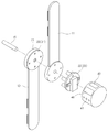
본 발명에 따르면 본체(10)가 힌지축(15) 상에 상부대(11)와 하부대(12)를 관절운동 가능하게 연결하는 구조이다. 도 1에서 한 쌍의 상부대(11) 및 좌우 한 쌍의 하부대(12)가 각각의 힌지축(15)을 개재하여 연결된 상태를 예시한다. 대향하는 상부대(11)를 연결하는 밴드(17) 및 대향하는 하부대(12)를 연결하는 밴드(17)는 복수로 구성하는 것이 좋다. 착용자의 신체 조건(굵기)에 대응하도록 밴드(17)에 벨크로테이프 등의 조임부(18)를 설치한다.According to the present invention, the
본 발명의 세부 구성으로서, 상기 본체(10)의 상부대(11)와 하부대(12)는 각각의 슬라이드부(13)를 개재하여 길이변동 가능하게 설치되는 것을 특징으로 한다. 착용자의 신체 조건(신장)에 대응하도록 상부대(11) 및 하부대(12)에 길이 조절이 가능한 방식의 슬라이드부(13)를 설치한다. 슬라이드부(13)는 상하 2부분으로 분리하여 암수로 결합하고 조임볼트(도시 생략) 등을 사용하여 고정할 수 있다.The upper and
한편, 본체(10)에서 신체와 접촉되는 부분에 탄성편(도시 생략)을 탈부착 가능한 방식으로 부가하는 것이 좋다. 탄성편은 상부대(11), 하부대(12), 밴드(17)의 내면에 벨크로테이프 방식으로 위치변동 가능하게 부착한다.On the other hand, an elastic piece (not shown) may be attached to the
또한, 본 발명에 따르면 완충수단(20)이 상기 본체(10)의 관절운동에 대응하여 마찰 저항력과 와전류 저항력을 작용하도록 구비된다. 완충수단(20)은 관절의 굴신 과정에서 상시적인 저항력을 발생할 수도 있고 한시적 또는 주기적 저항력을 발생할 수도 있다. 어느 경우에나 착용자의 보행을 조력하는 모션 유도하기 위한 마찰 저항력과 와전류 저항력을 작용한다. In addition, according to the present invention, the buffering means 20 is provided so as to exert frictional resistance and eddy current resistance in response to the joint motion of the
본 발명의 세부 구성으로서, 상기 완충수단(20)은 상부대(11)와 하부대(12)의 관절운동에 연동하도록 로터(21), 스테이터(22), 마찰체(25)를 구비하는 것을 특징으로 한다. 도 2를 참조하면 상부대(11)의 하단에 로터(21)를 부착하고, 하부대(12)의 상단에 스테이터(22)를 부착하며, 상부대(11)와 로터(21) 사이에 마찰체(25)를 결합한다. 스테이터(22)는 후술하는 제어수단(40)에 전기적으로 연결되는 여자코일(23)을 구비한다. 여자코일(23)에 인가되는 전류에 의하여 자장이 형성되고, 자장에 의하여 로터(21)에 발생되는 와전류 지속이 자장과 상호작용하여 제동력을 발생한다. 마찰체(25)는 기본적으로 기계적 마찰 저항력을 발생하지만 저항력의 전기적 변동이 가능하도록 구성되는 것이 바람직하다. 착용자의 보행 과정에서 로터(21) 및 스테이터(22)에 의한 와전류 제동이 미흡한 경우에도 마찰체(25)에 의하여 기본적 제동 기능이 제공된다.The buffering means 20 includes a
한편, 도 3에서 나타내는 것처럼 스테이터(22)를 중심으로 전후 방향에 로터(21)를 결합하는 것도 가능하다. 이는 로터(21)의 표면에 발생하는 와전류에 의한 자속 증가 및 이에 따른 저항력을 증가를 유발한다.On the other hand, as shown in FIG. 3, it is also possible to couple the
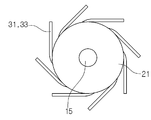
본 발명의 세부 구성으로서, 상기 마찰체(25)는 전기적 신호에 의하여 마찰 저항력을 변동하도록 EAP모듈(31)을 구비하는 것을 특징으로 한다. EAP모듈(31)은 전기활성고분자(Electro Active Polymer)를 기반으로 하는 것으로 액상, 고상, 또는 그 혼합물 형태로 적용될 수 있다. EAP모듈(31)의 구동용 신호는 제어수단(40)의 제어기(41) 및 전원부(43)에 의하여 변동적으로 인가된다. 전원부(43)의 직류 전원으로 EAP모듈(31)의 수축과 팽창이 유발되지만 원활한 운동성을 보조하기 위한 스프링 등을 병용할 수도 있다.As a detailed configuration of the present invention, the friction body (25) is provided with an EAP module (31) so as to change a frictional resistance force by an electrical signal. The
본 발명의 변형예로서, 상기 EAP모듈(31)은 고탄성섬유(33)와 근섬유를 형성하도록 결합되어 로터(21)의 외주면에 방사상으로 연결되는 것을 특징으로 한다. 도 4에서 8개의 근섬유 형태 EAP모듈(31)이 로터(21)의 외주면에 접선 방향으로 연결된 상태를 예시한다. 근섬유는 EAP섬유와 고탄성섬유(33)를 연사한 구성이 바람직하다. 이에 완충수단(20)의 마찰체(25)가 보행시 발생하는 관절부 충격을 주기적으로 흡수하면서 EAP모듈(31)의 기능성과 내구성을 증대한다.The
또한, 본 발명에 따르면 검출수단이 상기 본체(10)에 장착되어 보행 관련의 정보를 검출하는 구조이다. 검출수단은 정상적인 보행의 입각기(stance period)와 유각기(swing period)에 대응하는 신호를 검출한다. 검출된 신호는 제어수단(40)의 제어기(41)로 입력되어 완충수단(20)을 작동하는 출력으로 변환된다.Further, according to the present invention, the detecting means is mounted on the
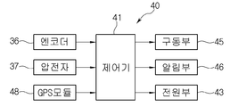
본 발명의 세부 구성으로서, 상기 검출수단은 관절의 회전 각도를 검출하는 엔코더(35), 관절에 작용하는 수직 하중을 검출하는 압전소자(37)를 구비하는 것을 특징으로 한다. 엔코더(35)는 상부대(11) 및 하부대(12) 사이의 각도 변동을 검출하도록 설치될 수 있다. 압전소자(37)는 상부대(11) 및 하부대(12) 사이의 수직 하중 변동을 검출하도록 설치될 수 있다. 어느 경우에나 엔코더(35)와 압전소자(37)는 경박단소 구조에 적합하도록 적어도 부분적으로 반도체 방식을 채용한다. 이외에 보행자의 이동 경로를 검출하기 위한 GPS모듈(48)을 부가할 수 있다.In the detailed construction of the present invention, the detection means is characterized by comprising an encoder (35) for detecting the rotation angle of the joint, and a piezoelectric element (37) for detecting a vertical load acting on the joint. The encoder 35 can be installed to detect an angular variation between the upper and
또한, 본 발명에 따르면 제어수단(40)이 상기 검출수단의 신호에 대응하여 설정된 알고리즘으로 완충수단(20)의 저항력을 변동한다. 제어수단(40)은 마이크로프로세서, 메모리, 입출력인터페이스를 탑재하는 제어기(41)를 기반으로 구성된다. 본 발명과 관련된 제어 알고리즘은 서브루틴 프로그램 형태로 메모리에 갱신 가능하게 저장된다. 도 5에서 제어기(41)의 입출력인터페이스를 통하여 연결되는 회로 구성을 예시한다.Further, according to the present invention, the control means (40) varies the resistance force of the buffer means (20) with an algorithm set corresponding to the signal of the detection means. The control means 40 is constituted based on a microprocessor, a memory, and a
본 발명의 세부 구성으로서, 상기 제어수단(40)은 작동전원을 제공하고 충전을 제어하는 전원부(43), 완충수단(20)에 인가되는 전원을 단속하는 구동부(45), 작동 상태를 시청각적으로 표시하는 알림부(46)를 구비하는 것을 특징으로 한다. 도 2에서 전원부(43), 구동부(45), 알림부(46)가 제어기(41)와 동일한 하우징에 수용된 상태를 예시한다. 전원부(43)는 충전 가능한 2차전지를 사용하며, 허리에 착용하는 보조배터리(도시 생략)를 포함할 수 있다. 구동부(45)는 입출력인터페이스의 출력을 전원부(43)의 전원으로 변환하여 인가한다. 알림부(46)는 디스플레이, 스피커를 포함하여 구성한다.The control means 40 includes a
작동의 일예로서, 착용자가 본체(10)를 다리에 착용하고 슬라이드부(13)과 조임부(18)로 조정을 완료하면, 보행하는 과정에서 마찰체(25)에 의한 완충이 기본적으로 수행되면서, 입각기와 유각기에 맞추어 EAP모듈(31)의 저항력이 변동되어 최적의 상태를 유지한다. 압전소자(37)와 GPS모듈(48)의 신호를 이용하여 소정의 연산을 거치면 보행한 거리와 에너지 소모를 추정할 수 있다. 모든 작동 프로세스와 관련 정보는 알림부(46)를 통하여 시청각적으로 표출된다.As an example of the operation, when the wearer wears the
본 발명은 기재된 실시예에 한정되는 것이 아니고, 본 발명의 사상 및 범위를 벗어나지 않고 다양하게 수정 및 변형할 수 있음이 이 기술의 분야에서 통상의 지식을 가진 자에게 자명하다. 따라서 그러한 변형예 또는 수정예들은 본 발명의 특허청구범위에 속한다 해야 할 것이다.It will be apparent to those skilled in the art that various modifications and variations can be made in the present invention without departing from the spirit and scope of the invention. It is therefore intended that such variations and modifications fall within the scope of the appended claims.
10: 본체
11: 상부대
12: 하부대
13: 슬라이드부
15: 힌지축
17: 밴드
20: 완충수단
21: 로터
22: 스테이터
23: 여자코일
25: 마찰체
31: EAP모듈
33: 고탄성섬유
35: 엔코더
37: 압전소자
40: 제어수단
41: 제어기
43: 전원부
45: 구동부
46: 알림부
48: GPS모듈10: Body 11:
12: lower part 13: slide part
15: Hinge shaft 17: Band
20: buffer means 21: rotor
22: stator 23: exciting coil
25: Friction body 31: EAP module
33: High elasticity fiber 35: Encoder
37: piezoelectric element 40: control means
41: controller 43:
45: driving unit 46:
48: GPS module
Claims (7)
힌지축(15) 상에 상부대(11)와 하부대(12)를 관절운동 가능하게 연결하는 본체(10);
상기 본체(10)의 관절운동에 대응하여 마찰 저항력과 와전류 저항력을 작용하도록 구비되는 완충수단(20);
상기 본체(10)에 장착되어 보행 관련의 정보를 검출하는 검출수단; 및
상기 검출수단의 신호에 대응하여 설정된 알고리즘으로 완충수단(20)의 저항력을 변동하는 제어수단(40);을 포함하여 이루어지는 것을 특징으로 하는 인체 관절의 모션 유도기구.A device for inducing motion worn around a human joint comprising:
A main body 10 for articulately connecting the upper and lower legs 11 and 12 on the hinge shaft 15;
A buffer means (20) provided to exert frictional resistance and eddy current resistance in response to joint motion of the main body (10);
Detecting means mounted on the main body (10) for detecting walking related information; And
And a control means (40) for varying the resistance of the buffer means (20) by an algorithm set corresponding to the signal of the detection means.
상기 본체(10)의 상부대(11)와 하부대(12)는 각각의 슬라이드부(13)를 개재하여 길이변동 가능하게 설치되는 것을 특징으로 하는 인체 관절의 모션 유도기구.The method according to claim 1,
Wherein the upper and lower legs (11, 12) of the main body (10) are provided so as to be variable in length through respective slide portions (13).
상기 완충수단(20)은 상부대(11)와 하부대(12)의 관절운동에 연동하도록 로터(21), 스테이터(22), 마찰체(25)를 구비하는 것을 특징으로 하는 인체 관절의 모션 유도기구.The method according to claim 1,
Wherein the buffer means 20 includes a rotor 21, a stator 22 and a friction member 25 for interlocking with the joint motion of the upper and lower legs 11 and 12, Induction mechanism.
상기 마찰체(25)는 전기적 신호에 의하여 마찰 저항력을 변동하도록 EAP모듈(31)을 구비하는 것을 특징으로 하는 인체 관절의 모션 유도기구.The method of claim 3,
Wherein the friction body (25) is provided with an EAP module (31) so as to change frictional resistance by an electrical signal.
상기 EAP모듈(31)은 고탄성섬유(33)와 근섬유를 형성하도록 결합되어 로터(21)의 외주면에 방사상으로 연결되는 것을 특징으로 하는 인체 관절의 모션 유도기구.The method of claim 4,
Wherein the EAP module (31) is coupled to form a muscle fiber with the high-elasticity fibers (33) and radially connected to the outer circumferential surface of the rotor (21).
상기 검출수단은 관절의 회전 각도를 검출하는 엔코더(35), 관절에 작용하는 수직 하중을 검출하는 압전소자(37)를 구비하는 것을 특징으로 하는 인체 관절의 모션 유도기구.The method according to claim 1,
Wherein the detecting means comprises an encoder (35) for detecting a rotation angle of the joint, and a piezoelectric element (37) for detecting a vertical load acting on the joint.
상기 제어수단(40)은 작동전원을 제공하고 충전을 제어하는 전원부(43), 완충수단(20)에 인가되는 전원을 단속하는 구동부(45), 작동 상태를 시청각적으로 표시하는 알림부(46)를 구비하는 것을 특징으로 하는 인체 관절의 모션 유도기구.The method according to claim 1,
The control means 40 includes a power supply portion 43 for supplying operating power and controlling charging, a driving portion 45 for interrupting the power applied to the buffering means 20, a notification portion 46 for visually displaying the operating state ) Of the human body joint.
Priority Applications (1)
| Application Number | Priority Date | Filing Date | Title |
|---|---|---|---|
| KR1020170025807A KR101896306B1 (en) | 2017-02-27 | 2017-02-27 | Device for guiding human body joint motion |
Applications Claiming Priority (1)
| Application Number | Priority Date | Filing Date | Title |
|---|---|---|---|
| KR1020170025807A KR101896306B1 (en) | 2017-02-27 | 2017-02-27 | Device for guiding human body joint motion |
Publications (2)
| Publication Number | Publication Date |
|---|---|
| KR20180098960A true KR20180098960A (en) | 2018-09-05 |
| KR101896306B1 KR101896306B1 (en) | 2018-09-10 |
Family
ID=63593982
Family Applications (1)
| Application Number | Title | Priority Date | Filing Date |
|---|---|---|---|
| KR1020170025807A Active KR101896306B1 (en) | 2017-02-27 | 2017-02-27 | Device for guiding human body joint motion |
Country Status (1)
| Country | Link |
|---|---|
| KR (1) | KR101896306B1 (en) |
Citations (6)
| Publication number | Priority date | Publication date | Assignee | Title |
|---|---|---|---|---|
| US4817588A (en) * | 1987-07-01 | 1989-04-04 | Medical Technology, Inc. | Motion restraining knee brace |
| US5052379A (en) * | 1989-04-27 | 1991-10-01 | Soma Dynamics Corporation | Combination brace and wearable exercise apparatus for body joints |
| US20040102723A1 (en) * | 2002-11-25 | 2004-05-27 | Horst Robert W. | Active muscle assistance device and method |
| US20080097269A1 (en) * | 2004-11-09 | 2008-04-24 | Brian Weinberg | Electro-Rheological Fluid Brake and Actuator Devices and Orthotic Devices Using the Same |
| KR101611042B1 (en) | 2014-06-03 | 2016-04-11 | 현대자동차주식회사 | System and method for controlling joint of wearable robot |
| KR101637114B1 (en) | 2015-02-13 | 2016-07-08 | 근로복지공단 | Knee joint of weight active type |
-
2017
- 2017-02-27 KR KR1020170025807A patent/KR101896306B1/en active Active
Patent Citations (6)
| Publication number | Priority date | Publication date | Assignee | Title |
|---|---|---|---|---|
| US4817588A (en) * | 1987-07-01 | 1989-04-04 | Medical Technology, Inc. | Motion restraining knee brace |
| US5052379A (en) * | 1989-04-27 | 1991-10-01 | Soma Dynamics Corporation | Combination brace and wearable exercise apparatus for body joints |
| US20040102723A1 (en) * | 2002-11-25 | 2004-05-27 | Horst Robert W. | Active muscle assistance device and method |
| US20080097269A1 (en) * | 2004-11-09 | 2008-04-24 | Brian Weinberg | Electro-Rheological Fluid Brake and Actuator Devices and Orthotic Devices Using the Same |
| KR101611042B1 (en) | 2014-06-03 | 2016-04-11 | 현대자동차주식회사 | System and method for controlling joint of wearable robot |
| KR101637114B1 (en) | 2015-02-13 | 2016-07-08 | 근로복지공단 | Knee joint of weight active type |
Also Published As
| Publication number | Publication date |
|---|---|
| KR101896306B1 (en) | 2018-09-10 |
Similar Documents
| Publication | Publication Date | Title |
|---|---|---|
| CN110652425B (en) | Variable-rigidity lower limb exoskeleton power-assisted robot | |
| EP3954351B1 (en) | Ankle-assisted exoskeleton device | |
| JP7345840B2 (en) | Flexible wearable muscle assist device | |
| US12569393B2 (en) | Cable-actuated, kinetically-balanced, parallel torque transfer exoskeleton joint actuator with or without strain sensing | |
| US11633319B2 (en) | Unpowered wearable walking assistance knee equipment with gait self-adaptivity | |
| EP2649976B1 (en) | Device for assisting joint exercise | |
| KR101836413B1 (en) | Tendon device of suit type exoskeleton for human power assistance | |
| KR102452632B1 (en) | A motion assist apparatus and a control method thereof | |
| CN106798630B (en) | Walking auxiliary machine and walking auxiliary machine set | |
| JP5876550B1 (en) | Joint motion assist device | |
| RU2414207C2 (en) | Device facilitating walking | |
| JP6791715B2 (en) | Joint assembly and exercise assist device including it | |
| JPWO2012086202A1 (en) | Joint support orthosis and rehabilitation device | |
| JP7363439B2 (en) | Walking aid device and its control method | |
| WO2021116721A1 (en) | Motion assistance device | |
| JP2016168191A (en) | Joint motion assist device | |
| KR20210053976A (en) | Wearable active assistive device | |
| WO2021032970A1 (en) | Joint motion capture | |
| US20210315514A1 (en) | Wearable passive assisting device | |
| KR101896306B1 (en) | Device for guiding human body joint motion | |
| KR101058436B1 (en) | Walking aid using magnetorheological fluid damper | |
| CN110787023B (en) | Inhaul cable power device, power system thereof, power assisting equipment and control method thereof | |
| JP2021126219A (en) | Walking assist device | |
| US20260069923A1 (en) | Wearable device and electronic device for providing customized exercise coaching function and operating method thereof | |
| KR20250105092A (en) | Wearable device with joint angle calibration function and operation methof thereof |
Legal Events
| Date | Code | Title | Description |
|---|---|---|---|
| A201 | Request for examination | ||
| PA0109 | Patent application |
Patent event code: PA01091R01D Comment text: Patent Application Patent event date: 20170227 |
|
| PA0201 | Request for examination | ||
| E902 | Notification of reason for refusal | ||
| PE0902 | Notice of grounds for rejection |
Comment text: Notification of reason for refusal Patent event date: 20180222 Patent event code: PE09021S01D |
|
| E701 | Decision to grant or registration of patent right | ||
| PE0701 | Decision of registration |
Patent event code: PE07011S01D Comment text: Decision to Grant Registration Patent event date: 20180829 |
|
| GRNT | Written decision to grant | ||
| PR0701 | Registration of establishment |
Comment text: Registration of Establishment Patent event date: 20180903 Patent event code: PR07011E01D |
|
| PR1002 | Payment of registration fee |
Payment date: 20180904 End annual number: 3 Start annual number: 1 |
|
| PG1501 | Laying open of application | ||
| PG1601 | Publication of registration | ||
| PR1001 | Payment of annual fee |
Payment date: 20210715 Start annual number: 4 End annual number: 4 |
|
| PR1001 | Payment of annual fee |
Payment date: 20230621 Start annual number: 6 End annual number: 6 |
|
| PR1001 | Payment of annual fee |
Payment date: 20240626 Start annual number: 7 End annual number: 7 |
|
| PR1001 | Payment of annual fee |
Payment date: 20250626 Start annual number: 8 End annual number: 8 |