JP7345840B2 - Flexible wearable muscle assist device - Google Patents
Flexible wearable muscle assist device Download PDFInfo
- Publication number
- JP7345840B2 JP7345840B2 JP2019535945A JP2019535945A JP7345840B2 JP 7345840 B2 JP7345840 B2 JP 7345840B2 JP 2019535945 A JP2019535945 A JP 2019535945A JP 2019535945 A JP2019535945 A JP 2019535945A JP 7345840 B2 JP7345840 B2 JP 7345840B2
- Authority
- JP
- Japan
- Prior art keywords
- joint
- assist device
- tendon
- garment
- flexible wearable
- Prior art date
- Legal status (The legal status is an assumption and is not a legal conclusion. Google has not performed a legal analysis and makes no representation as to the accuracy of the status listed.)
- Active
Links
Images


Classifications
-
- A—HUMAN NECESSITIES
- A61—MEDICAL OR VETERINARY SCIENCE; HYGIENE
- A61H—PHYSICAL THERAPY APPARATUS, e.g. DEVICES FOR LOCATING OR STIMULATING REFLEX POINTS IN THE BODY; ARTIFICIAL RESPIRATION; MASSAGE; BATHING DEVICES FOR SPECIAL THERAPEUTIC OR HYGIENIC PURPOSES OR SPECIFIC PARTS OF THE BODY
- A61H1/00—Apparatus for passive exercising; Vibrating apparatus ; Chiropractic devices, e.g. body impacting devices, external devices for briefly extending or aligning unbroken bones
- A61H1/02—Stretching or bending or torsioning apparatus for exercising
- A61H1/0237—Stretching or bending or torsioning apparatus for exercising for the lower limbs
- A61H1/0244—Hip
-
- A—HUMAN NECESSITIES
- A61—MEDICAL OR VETERINARY SCIENCE; HYGIENE
- A61H—PHYSICAL THERAPY APPARATUS, e.g. DEVICES FOR LOCATING OR STIMULATING REFLEX POINTS IN THE BODY; ARTIFICIAL RESPIRATION; MASSAGE; BATHING DEVICES FOR SPECIAL THERAPEUTIC OR HYGIENIC PURPOSES OR SPECIFIC PARTS OF THE BODY
- A61H1/00—Apparatus for passive exercising; Vibrating apparatus ; Chiropractic devices, e.g. body impacting devices, external devices for briefly extending or aligning unbroken bones
- A61H1/02—Stretching or bending or torsioning apparatus for exercising
- A61H1/0237—Stretching or bending or torsioning apparatus for exercising for the lower limbs
- A61H1/0255—Both knee and hip of a patient, e.g. in supine or sitting position, the feet being moved in a plane substantially parallel to the body-symmetrical-plane
-
- A—HUMAN NECESSITIES
- A61—MEDICAL OR VETERINARY SCIENCE; HYGIENE
- A61H—PHYSICAL THERAPY APPARATUS, e.g. DEVICES FOR LOCATING OR STIMULATING REFLEX POINTS IN THE BODY; ARTIFICIAL RESPIRATION; MASSAGE; BATHING DEVICES FOR SPECIAL THERAPEUTIC OR HYGIENIC PURPOSES OR SPECIFIC PARTS OF THE BODY
- A61H1/00—Apparatus for passive exercising; Vibrating apparatus ; Chiropractic devices, e.g. body impacting devices, external devices for briefly extending or aligning unbroken bones
- A61H1/02—Stretching or bending or torsioning apparatus for exercising
- A61H1/0237—Stretching or bending or torsioning apparatus for exercising for the lower limbs
- A61H1/024—Knee
-
- A—HUMAN NECESSITIES
- A61—MEDICAL OR VETERINARY SCIENCE; HYGIENE
- A61H—PHYSICAL THERAPY APPARATUS, e.g. DEVICES FOR LOCATING OR STIMULATING REFLEX POINTS IN THE BODY; ARTIFICIAL RESPIRATION; MASSAGE; BATHING DEVICES FOR SPECIAL THERAPEUTIC OR HYGIENIC PURPOSES OR SPECIFIC PARTS OF THE BODY
- A61H1/00—Apparatus for passive exercising; Vibrating apparatus ; Chiropractic devices, e.g. body impacting devices, external devices for briefly extending or aligning unbroken bones
- A61H1/02—Stretching or bending or torsioning apparatus for exercising
- A61H1/0237—Stretching or bending or torsioning apparatus for exercising for the lower limbs
- A61H1/0255—Both knee and hip of a patient, e.g. in supine or sitting position, the feet being moved in a plane substantially parallel to the body-symmetrical-plane
- A61H1/0262—Walking movement; Appliances for aiding disabled persons to walk
-
- A—HUMAN NECESSITIES
- A61—MEDICAL OR VETERINARY SCIENCE; HYGIENE
- A61H—PHYSICAL THERAPY APPARATUS, e.g. DEVICES FOR LOCATING OR STIMULATING REFLEX POINTS IN THE BODY; ARTIFICIAL RESPIRATION; MASSAGE; BATHING DEVICES FOR SPECIAL THERAPEUTIC OR HYGIENIC PURPOSES OR SPECIFIC PARTS OF THE BODY
- A61H1/00—Apparatus for passive exercising; Vibrating apparatus ; Chiropractic devices, e.g. body impacting devices, external devices for briefly extending or aligning unbroken bones
- A61H1/02—Stretching or bending or torsioning apparatus for exercising
- A61H1/0274—Stretching or bending or torsioning apparatus for exercising for the upper limbs
- A61H1/0277—Elbow
-
- A—HUMAN NECESSITIES
- A61—MEDICAL OR VETERINARY SCIENCE; HYGIENE
- A61H—PHYSICAL THERAPY APPARATUS, e.g. DEVICES FOR LOCATING OR STIMULATING REFLEX POINTS IN THE BODY; ARTIFICIAL RESPIRATION; MASSAGE; BATHING DEVICES FOR SPECIAL THERAPEUTIC OR HYGIENIC PURPOSES OR SPECIFIC PARTS OF THE BODY
- A61H1/00—Apparatus for passive exercising; Vibrating apparatus ; Chiropractic devices, e.g. body impacting devices, external devices for briefly extending or aligning unbroken bones
- A61H1/02—Stretching or bending or torsioning apparatus for exercising
- A61H1/0274—Stretching or bending or torsioning apparatus for exercising for the upper limbs
- A61H1/0281—Shoulder
-
- A—HUMAN NECESSITIES
- A61—MEDICAL OR VETERINARY SCIENCE; HYGIENE
- A61H—PHYSICAL THERAPY APPARATUS, e.g. DEVICES FOR LOCATING OR STIMULATING REFLEX POINTS IN THE BODY; ARTIFICIAL RESPIRATION; MASSAGE; BATHING DEVICES FOR SPECIAL THERAPEUTIC OR HYGIENIC PURPOSES OR SPECIFIC PARTS OF THE BODY
- A61H3/00—Appliances for aiding patients or disabled persons to walk about
-
- B—PERFORMING OPERATIONS; TRANSPORTING
- B25—HAND TOOLS; PORTABLE POWER-DRIVEN TOOLS; MANIPULATORS
- B25J—MANIPULATORS; CHAMBERS PROVIDED WITH MANIPULATION DEVICES
- B25J9/00—Programme-controlled manipulators
- B25J9/0006—Exoskeletons, i.e. resembling a human figure
-
- A—HUMAN NECESSITIES
- A61—MEDICAL OR VETERINARY SCIENCE; HYGIENE
- A61H—PHYSICAL THERAPY APPARATUS, e.g. DEVICES FOR LOCATING OR STIMULATING REFLEX POINTS IN THE BODY; ARTIFICIAL RESPIRATION; MASSAGE; BATHING DEVICES FOR SPECIAL THERAPEUTIC OR HYGIENIC PURPOSES OR SPECIFIC PARTS OF THE BODY
- A61H2201/00—Characteristics of apparatus not provided for in the preceding codes
- A61H2201/01—Constructive details
- A61H2201/0173—Means for preventing injuries
- A61H2201/0176—By stopping operation
-
- A—HUMAN NECESSITIES
- A61—MEDICAL OR VETERINARY SCIENCE; HYGIENE
- A61H—PHYSICAL THERAPY APPARATUS, e.g. DEVICES FOR LOCATING OR STIMULATING REFLEX POINTS IN THE BODY; ARTIFICIAL RESPIRATION; MASSAGE; BATHING DEVICES FOR SPECIAL THERAPEUTIC OR HYGIENIC PURPOSES OR SPECIFIC PARTS OF THE BODY
- A61H2201/00—Characteristics of apparatus not provided for in the preceding codes
- A61H2201/12—Driving means
- A61H2201/1207—Driving means with electric or magnetic drive
- A61H2201/1215—Rotary drive
-
- A—HUMAN NECESSITIES
- A61—MEDICAL OR VETERINARY SCIENCE; HYGIENE
- A61H—PHYSICAL THERAPY APPARATUS, e.g. DEVICES FOR LOCATING OR STIMULATING REFLEX POINTS IN THE BODY; ARTIFICIAL RESPIRATION; MASSAGE; BATHING DEVICES FOR SPECIAL THERAPEUTIC OR HYGIENIC PURPOSES OR SPECIFIC PARTS OF THE BODY
- A61H2201/00—Characteristics of apparatus not provided for in the preceding codes
- A61H2201/14—Special force transmission means, i.e. between the driving means and the interface with the user
- A61H2201/1481—Special movement conversion means
- A61H2201/149—Special movement conversion means rotation-linear or vice versa
-
- A—HUMAN NECESSITIES
- A61—MEDICAL OR VETERINARY SCIENCE; HYGIENE
- A61H—PHYSICAL THERAPY APPARATUS, e.g. DEVICES FOR LOCATING OR STIMULATING REFLEX POINTS IN THE BODY; ARTIFICIAL RESPIRATION; MASSAGE; BATHING DEVICES FOR SPECIAL THERAPEUTIC OR HYGIENIC PURPOSES OR SPECIFIC PARTS OF THE BODY
- A61H2201/00—Characteristics of apparatus not provided for in the preceding codes
- A61H2201/16—Physical interface with patient
- A61H2201/1602—Physical interface with patient kind of interface, e.g. head rest, knee support or lumbar support
- A61H2201/165—Wearable interfaces
-
- A—HUMAN NECESSITIES
- A61—MEDICAL OR VETERINARY SCIENCE; HYGIENE
- A61H—PHYSICAL THERAPY APPARATUS, e.g. DEVICES FOR LOCATING OR STIMULATING REFLEX POINTS IN THE BODY; ARTIFICIAL RESPIRATION; MASSAGE; BATHING DEVICES FOR SPECIAL THERAPEUTIC OR HYGIENIC PURPOSES OR SPECIFIC PARTS OF THE BODY
- A61H2201/00—Characteristics of apparatus not provided for in the preceding codes
- A61H2201/50—Control means thereof
- A61H2201/5058—Sensors or detectors
- A61H2201/5061—Force sensors
-
- A—HUMAN NECESSITIES
- A61—MEDICAL OR VETERINARY SCIENCE; HYGIENE
- A61H—PHYSICAL THERAPY APPARATUS, e.g. DEVICES FOR LOCATING OR STIMULATING REFLEX POINTS IN THE BODY; ARTIFICIAL RESPIRATION; MASSAGE; BATHING DEVICES FOR SPECIAL THERAPEUTIC OR HYGIENIC PURPOSES OR SPECIFIC PARTS OF THE BODY
- A61H2201/00—Characteristics of apparatus not provided for in the preceding codes
- A61H2201/50—Control means thereof
- A61H2201/5058—Sensors or detectors
- A61H2201/5069—Angle sensors
-
- A—HUMAN NECESSITIES
- A61—MEDICAL OR VETERINARY SCIENCE; HYGIENE
- A61H—PHYSICAL THERAPY APPARATUS, e.g. DEVICES FOR LOCATING OR STIMULATING REFLEX POINTS IN THE BODY; ARTIFICIAL RESPIRATION; MASSAGE; BATHING DEVICES FOR SPECIAL THERAPEUTIC OR HYGIENIC PURPOSES OR SPECIFIC PARTS OF THE BODY
- A61H2201/00—Characteristics of apparatus not provided for in the preceding codes
- A61H2201/50—Control means thereof
- A61H2201/5058—Sensors or detectors
- A61H2201/5071—Pressure sensors
-
- A—HUMAN NECESSITIES
- A61—MEDICAL OR VETERINARY SCIENCE; HYGIENE
- A61H—PHYSICAL THERAPY APPARATUS, e.g. DEVICES FOR LOCATING OR STIMULATING REFLEX POINTS IN THE BODY; ARTIFICIAL RESPIRATION; MASSAGE; BATHING DEVICES FOR SPECIAL THERAPEUTIC OR HYGIENIC PURPOSES OR SPECIFIC PARTS OF THE BODY
- A61H2201/00—Characteristics of apparatus not provided for in the preceding codes
- A61H2201/50—Control means thereof
- A61H2201/5058—Sensors or detectors
- A61H2201/5084—Acceleration sensors
Description
本発明は、柔軟な装着型筋肉補助装置に関する。 FIELD OF THE INVENTION The present invention relates to a flexible wearable muscle assist device.
筋骨格系の弱さは、人間の生活の質を低下させる問題を生じる可能性がある。このような弱さは、遺伝的異常の結果、発作などの神経状態の結果または老化によるものである可能性がある。弱さにより、人間は、髪をとかすときに腕を上げることができなかったり、スムーズに立ち上がるまたは座ることができなかったり、階段を上ることができなかったりすることがある。 Weakness of the musculoskeletal system can create problems that reduce a person's quality of life. Such weakness may be the result of genetic abnormalities, neurological conditions such as seizures, or due to aging. Weakness may cause a person to be unable to raise their arms when combing their hair, stand up or sit down smoothly, or climb stairs.
これは、たとえ影響される人間がまだ腕、足またはその他の末端を動かすことができるとしても起こりえる。すなわち、人間が筋肉のどのグループに対してもコントロールできない完全な対麻痺などの状況とは対照的に、筋肉のうちの少なくとも幾つかをコントロールすることができる。しかしながら、人間が四肢を動かすために必要とする筋肉または筋肉のうちの少なくとも幾つかが弱すぎるとしても、特に筋肉が四肢の位置を重力に逆らって維持しなければならないかまたは体の一部を重力に逆らって持ち上げなければならない場合、例えば、歩行中に足先、大腿などを持ち上げなければならないとき、人間は、四肢を部分的にコントロールする能力を維持している。時には、このような状態は、例えば事故に遭った後に、負傷した筋肉を用いて動きを再訓練する必要があるような、一時的な性質のものでしかない。しかしながら、そのようなときでも、人間が弱さによって障害を生じる時間が、かなり長くなることがある。さらに、継続的な障害が予想されるような多くの条件も存在する。 This can occur even if the affected person is still able to move their arms, legs, or other extremities. That is, at least some of the muscles can be controlled, as opposed to situations such as complete paraplegia, where a person has no control over any group of muscles. However, even if the muscles or at least some of the muscles that humans need to move their limbs are too weak, especially if the muscles have to maintain the position of a limb against gravity or move a part of the body. Humans retain the ability to partially control their limbs when they have to lift against gravity, for example when they have to lift their toes, thighs, etc. while walking. Sometimes such a condition is only of a temporary nature, for example after an accident, when the injured muscles need to be retrained to move. However, even in such cases, the amount of time that humans are impaired by their weaknesses can be quite long. In addition, there are many conditions under which continued failure may be expected.
したがって、筋骨格系の弱さによって影響される人間のための日常生活の活動を改善する必要がある。これは、特に、自分の体重を重力に逆らって支えることができないことにより、コミュニティーの中を移動するときに危険が生じることがあるような場合である。これは、可動性の一般的な欠如を生じる可能性があり、ひいては、関節痛または心臓血管的欠乏などの併存症につながる可能性があり、これらは全て、動きの全体的な減少に由来する。 Therefore, there is a need to improve activities of daily living for humans affected by musculoskeletal weakness. This is particularly the case where the inability to support one's weight against gravity may pose a danger when moving through the community. This can result in a general lack of mobility, which in turn can lead to comorbidities such as joint pain or cardiovascular deficiencies, all of which result from an overall reduction in movement. .
別の例として、半身麻痺のある腕を有する脳卒中生存者は、日常生活の活動のために腕を使用することができないので、腕の使用を止める選択をすることがある。これは、転じて、学習された不使用として知られる現象につながる。これは、腕の使用の欠如が悪循環につながり、患者が腕の使用を完全に止めることがある状態である。動きを減らすかまたは抑制するこれらの行動は、回復を促進するために動きが行われる身体的リハビリテーションの一般的アプローチに反する。 As another example, a stroke survivor with a paraplegic arm may choose to stop using the arm because they are unable to use it for activities of daily living. This, in turn, leads to a phenomenon known as learned disuse. This is a condition where lack of use of the arm can lead to a vicious cycle and the patient may stop using the arm altogether. These actions that reduce or inhibit movement run counter to the common approach of physical rehabilitation, where movement is performed to promote recovery.
電動式外骨格の形式で人間に補助を提供することが既に提案されている。これらの装置は、歩行または起立などの動きを助けるために使用者に力を加える。このために、人間の骨格の関節の近くに配置された機械的関節が設けられた剛性構造が使用される。外骨格は、外骨格の関節を曲げまたは伸ばし、これにより補助のために必要とされる力を伝達するための電気モータを有する。このような外骨格は、例えば、完全な対麻痺を有する人にとって非常に役立つことがあるが、剛性の外骨格は、かさ高で、重くかつ高価になる傾向がある。 It has already been proposed to provide assistance to humans in the form of motorized exoskeletons. These devices apply force to the user to assist in movements such as walking or standing. For this, rigid structures are used that are provided with mechanical joints located close to the joints of the human skeleton. The exoskeleton has an electric motor to bend or extend the joints of the exoskeleton and thereby transmit the forces required for assistance. Such exoskeletons can be very useful, for example, for people with complete paraplegia, but rigid exoskeletons tend to be bulky, heavy, and expensive.
また、特に外骨格の関節が人体の関節と正確に位置合わせされていない場合、剛性の外骨格の装着が不快であることがある。また、特に人間が深刻なハンディキャップを有するとき、人間を外骨格に収容するのが困難であることがある。 Also, wearing a rigid exoskeleton can be uncomfortable, especially if the joints of the exoskeleton are not precisely aligned with the joints of the human body. It can also be difficult to accommodate humans in exoskeletons, especially when humans have severe handicaps.
使用者のための筋肉サポートは、最初は軍事的用途のために開発された一連のプロジェクトにおいても提案されてきた。米国国防総省DARPA(高等研究計画局)による要求から始められたこれらのプロジェクトは、重い機材を運搬することによって生じる兵士の筋骨格負傷を減らす技術を開発しようとした。兵士が機材を運搬しているときに、足に注意深くタイミングが合わせられた補助的な力を提供することが提案された。エクソスーツとして知られるこのような装置は、外骨格のかさ高および重量の問題のうちの幾つかを克服したが、軍事目的のために開発されたエクソスーツは、障害のある人間にはほとんど適していない。丈夫な体の、十分に訓練された兵士のために開発された軍事用エクソスーツは、歩行サイクルの特定の段階で短いバーストの補助を提供するために、単純な位置ベース制御装置に依存することができる。しかしながら、障害のある人のニーズは、これらのバーストを超える。 Muscular support for users has also been proposed in a series of projects initially developed for military applications. These projects, initiated at the request of the US Department of Defense DARPA (Advanced Research Projects Agency), sought to develop techniques to reduce musculoskeletal injuries to soldiers caused by carrying heavy equipment. It was proposed to provide a carefully timed supplemental force to the foot while the soldier was carrying equipment. Such devices, known as exosuits, have overcome some of the bulk and weight problems of exoskeletons, but exosuits developed for military purposes are largely unsuitable for humans with disabilities. . Developed for hard-bodied, well-trained soldiers, military exosuits can rely on simple position-based control devices to provide short bursts of assistance during specific stages of the gait cycle. can. However, the needs of people with disabilities exceed these bursts.
補助の短いバーストがいくぶん不正確なタイミングであるとき、例えば、タイミングが、正確な歩行サイクルを備えた位相と僅かにまたは著しくずれているとき、またはバーストが、兵士および機材を完全に支持するためには弱すぎるとき、このような誤りは、軍事用エクソスーツからの有用な補助を全体的にかつそれにもかかわらず受ける十分に訓練された体により、兵士によって容易に修正される。対照的に、補助が障害のある人に提供されかつこのような補助が短すぎ、弱すぎまたは強すぎるかまたは誤ったタイミングで提供されると、エクソスーツを使用する障害のある人は、意図した動きを達成することができず、または転倒することさえある。 When short bursts of assistance are somewhat imprecisely timed, e.g. when the timing is slightly or significantly out of phase with the correct gait cycle, or because the burst fully supports soldiers and equipment. Such errors are easily corrected by the soldier due to his well-trained body, which overall and nevertheless receives useful assistance from the military exosuit. In contrast, if assistance is provided to a person with a disability, and such assistance is provided too briefly, too weakly or too strongly, or at the wrong time, the person using the exosuit may not be able to use the exosuit as intended. Unable to accomplish movements or even fall.
別の問題は、エクソスーツの使用者への力の伝達が、必要な補助を提供するために高いせん断力に依存するということである。これらの力は、大きな不快感につながる可能性があり、さらには、特に潜在的な使用者が、このような力またはそれらの不都合な効果を感じることを妨げる感覚的問題を有することがある場合、皮膚または体に対するさらなる負傷を生じることさえある。 Another problem is that the transmission of force to the user of the exosuit relies on high shear forces to provide the necessary assistance. These forces can lead to great discomfort, and even more so, especially if potential users may have sensory issues that prevent them from feeling such forces or their untoward effects. , even causing further injury to the skin or body.
このような従来の装置の例は、Walsh、Conor他によって出願された、人間の動きを補助するための柔軟なエクソスーツについての米国特許出願公開第14/893934号明細書である。人間の運動を補助するための別の柔軟なエクソスーツは、米国特許出願公開第14/660704号明細書として、Asbeck、Alan Thomas他によって出願されている。別のエクソスーツは、Kornbluh、Roy David他により、米国特許出願公開第14/207233号明細書に開示されている。上述のWalsh、Conor他は、米国特許出願公開第15/025472号明細書として、突出する部材を有する整形外科装置のための特許出願も出願している。別の従来技術は、米国特許出願公開第13/520102号明細書における、Bureau、Maxime、Je Hyung JungおよびThierry Kellerによる、制御された剛性を有するフィッティングエレメントである。 An example of such a conventional device is US Patent Application Publication No. 14/893,934 filed by Walsh, Conor et al. for a flexible exosuit to assist human movement. Another flexible exosuit for assisting human movement has been filed by Asbeck, Alan Thomas et al. in US Patent Application Publication No. 14/660,704. Another exosuit is disclosed by Kornbluh, Roy David et al. in US Patent Application Publication No. 14/207,233. The above-mentioned Walsh, Conor et al. have also filed a patent application for an orthopedic device having a protruding member, US Patent Application Publication No. 15/025,472. Another prior art is a fitting element with controlled stiffness by Bureau, Maxime, Je Hyung Jung and Thierry Keller in US Patent Application Publication No. 13/520,102.
Asbeck、Alan T.他は、リハビリテーションロボティクス(ICORR)、2013IEEE国際カンファレンス、IEEE、2013年において、論文“Biologically-inspired soft exosuit”を発表した。Wehner、Michael他は、ロボティクスおよびオートメーション(ICRA)、2013IEEE国際カンファレンス、IEEE、2013年において、論文“A lightweight soft exosuit for gait assistance”を発表した。Asbeck、Alan T.他は、IEEEロボティクス&オートメーションマガジン、第21巻、第4号、第22~33頁、2014年12月において、論文“Stronger, Smarter, Softer: NextGeneration Wearable Robots”を発表した。Panizzolo、Fausto A他は、Journal of NeuroEngineering and Rehabilitation、13:43、2016年における、“A biologically-inspired multi-joint soft exosuit that can reduce the energy cost of loaded walking”の著者である。Lobo-Prat、Joan他は、第5回IEEE RAS/EMBS International Conference on Biomedical Robotics and Biomechatronics、IEEE、2014年において、“Design and control of an experimental active elbow support for adult Duchenne Muscular Dystrophy patients”についての論文を発表した。著者Lobo-Prat、Joan他は、リハビリテーションロボティクス(ICORR)に関する2015IEEE国際カンファレンス、IEEE、2015年において、“Adaptive gravity and joint stiffness compensation methods for force-controlled arm supports”を発表した。最後に、Portema、Eric(2015)は、“Design of the Act In Arm: a novel planar active arm support for assisting people with Duchenne Muscular Dystrophy during table-top tasks”を発表し、In, Hyunki他は、IEEEロボティクス&オートメーションマガジン、第22巻、第1号、第97~105頁、2015年3月において、“Exo-Glove: A Wearable Robot for the Hand with a Soft Tendon Routing System”を発表した。
Asbeck, Alan T. et al. presented a paper “Biologically-inspired soft exosuit” at the 2013 IEEE International Conference on Rehabilitation Robotics (ICORR), IEEE, 2013. Wehner, Michael et al. presented the paper “A lightweight soft exosuit for gait assistance” at the 2013 IEEE International Conference on Robotics and Automation (ICRA), IEEE, 2013. Asbeck, Alan T. et al. published the paper “Stronger, Smarter, Softer: NextGeneration Wearable Robots” in IEEE Robotics & Automation Magazine,
拡張された要約として、2016年10月13日にKai SchmidtおよびR.Robert Rienerによって最初にオンラインにされた以下の文献“MAXX: Mobility Assisting textile eXoskeleton that Exploits Neural Control Synergies”も参照される。 For an expanded summary, reference may also be made to the following document “MAXX: Mobility Assisting textile eXoskeleton that Exploits Neural Control Synergies”, first brought online by Kai Schmidt and R. Robert Riener on October 13, 2016.
これを考慮して、本発明の目的は、日常生活の活動のために適しており、様々な状況において十分に快適に使用され、かつ異なる使用者および/または所定の使用者の変化する医学的条件に容易に適応させることができる、改良された柔軟な装着型筋肉補助装置を提供することである。 Considering this, it is an object of the present invention to be suitable for activities of daily living, comfortable enough to use in various situations, and suitable for different users and/or the changing medical needs of a given user. An object of the present invention is to provide an improved flexible wearable muscle assist device that can be easily adapted to conditions.
この問題に対する解決手段は、独立請求項で請求されている。好ましい実施の形態は、従属請求項で請求されており、詳細な説明のあらゆる箇所に見つけることもできる。 A solution to this problem is claimed in the independent claim. Preferred embodiments are claimed in the dependent claims and can also be found elsewhere in the detailed description.
詳細な説明にわたって、例えば、(彼女ではなく)彼の筋肉を動かす使用者がしばしば言及されることに留意すべきである。これは、読解を単純にする。これは、本発明の装置が男性使用者のみのために使用されることを示唆するものではない。これに留意して、本発明の装置は、男女両方のために使用することができ、人間は、大人、若者または子供であってよいことが理解されるであろう。 It should be noted that throughout the detailed description, for example, the user moving his (rather than her) muscles is often mentioned. This simplifies reading comprehension. This is not to suggest that the device of the invention is to be used only for male users. With this in mind, it will be appreciated that the device of the invention can be used for both men and women, and that the human being can be an adult, a young person or a child.
したがって、本発明の第1の態様では、柔軟な装着型筋肉補助装置は、少なくとも装着型のボディインターフェースを有しており、装着型ボディインターフェースには能動的構成部材および受動的構成部材のエレメントが取り付けられており、能動的構成部材および受動的構成部材は共に、使用者が、第2の身体部分に連結された第1の身体部分の位置を変化させるかまたは支持することを補助するように適応されている。柔軟な装着型筋肉補助装置は、さらに、少なくとも2つのガーメント部分を有しており、能動的構成部材および受動的構成部材は、少なくとも1つの能動的に動力が与えられるエレメントを有しており、受動的構成部材は、少なくとも第1の受動的構成部材および第2の受動的構成部材を有しており、両受動的構成部材は、少なくとも2つのガーメント構成部材の間に延びており、使用者によっておよび/または少なくとも1つの能動的に動力が与えられるエレメントによって提供されるエネルギを蓄えるための弾性材料を有しており、このようなスーツのために、第1および第2の受動的構成部材が身体の関節の互いに反対側に配置されることが提案される。 Accordingly, in a first aspect of the invention, a flexible wearable muscle assist device has at least a wearable body interface, the wearable body interface including active and passive component elements. The active component and the passive component are both attached to assist the user in changing the position or supporting the first body part coupled to the second body part. It has been adapted. The flexible wearable muscle assist device further has at least two garment portions, the active component and the passive component having at least one actively powered element; The passive components have at least a first passive component and a second passive component, both passive components extending between the at least two garment components, and wherein the passive components extend between the at least two garment components. and/or a resilient material for storing energy provided by and/or at least one actively powered element, and for such a suit, first and second passive components. are proposed to be placed on opposite sides of the joint of the body.
このように、付加的なトルクを加えることによって(または身体部分において引っ張ることによって)弾性材料を含む受動的構成部材を有する本発明の柔軟な装着型筋肉補助装置は、身体を動かす筋肉を補助するだけでなく、負傷、身体の筋肉のあるグループの学習された不使用などにより身体の靭帯が弱まったところも補助する。これらの条件は、筋肉自体に影響するだけでなく、長期的に、痛み、身体関節の広範囲の摩耗などを生じる正しくない姿勢にもつながることがある。 Thus, by applying additional torque (or by pulling on a body part), the flexible wearable muscle assist device of the present invention having a passive component comprising an elastic material assists the muscles in moving the body. It also assists where the body's ligaments have weakened due to injury or learned disuse of certain muscle groups in the body. These conditions not only affect the muscles themselves, but can also lead to incorrect posture, which can lead to pain, extensive wear and tear on body joints, etc. in the long term.
したがって、装着型ボディインターフェースのガーメント構成部材の間に延びる、関節における1つの受動的構成部材だけではなく、関節の2つの反対側に配置することができるように少なくとも2つの受動的構成部材を提供することで、第1の身体部分を位置付けるときの筋肉と、前述のとおり、しばしば同様に障害が生じる身体の靭帯との両方を補助することができる。 Thus, instead of just one passive component at the joint extending between the garment components of the wearable body interface, at least two passive components are provided so that they can be placed on two opposite sides of the joint. This can assist both the muscles in positioning the first body part and, as mentioned above, the ligaments of the body, which are also often impaired.
したがって、学習された不使用のリスクおよび結果が打ち消され、また、使用者の幾つかの筋肉または筋肉グループが弱いかまたは機能しないときでさえも、人体の筋肉は、健康な人間の動きにより密接に対応した形式で身体部分を動かすことができる。 Therefore, the learned risks and consequences of non-use are counteracted, and even when some muscles or muscle groups of the user are weak or non-functional, the muscles of the human body are more closely aligned with healthy human movements. You can move your body parts in a manner that corresponds to your body.
これは、低減された補助の使用を可能にし、その結果、アクチュエータサイズ、電池サイズなどの減少につながり、ひいては装置の重量およびコストの減少につながる。 This allows the use of reduced aids, resulting in a reduction in actuator size, battery size, etc., which in turn leads to a reduction in device weight and cost.
装着型ボディインターフェースは、使用者の皮膚と直接接触してもよいし、または装着型ボディインターフェースは下着、服などの上から装着されてもよいことに留意すべきである。直接皮膚の上にボディインターフェースを装着することが好ましいことがある。なぜならば、これは、装着型ボディインターフェースと皮膚との間で服がしわになることによる使用者の不快感を回避するからである。 It should be noted that the wearable body interface may be in direct contact with the user's skin, or the wearable body interface may be worn over underwear, clothing, etc. It may be preferable to wear the body interface directly on the skin. This is because this avoids user discomfort due to clothing wrinkles between the wearable body interface and the skin.
また、従来の(ただし、必要であれば大きなサイズの)服の下に装着される場合、柔軟な装着型筋肉補助装置の少なくともある構成部材を隠すことがより容易になるだろう。これは、特定の使用者にとって好ましい。 It would also be easier to conceal at least some components of the flexible wearable muscle assist device when worn under conventional (but larger size if necessary) clothing. This is preferred for certain users.
しかしながら、使用者の皮膚とボディインターフェースとの間に直接接触がないことが好ましい場合もある。なぜなら、例えばこの場合は、頻繁な洗濯、変化する周囲温度への適応などを可能にするために、使用者が下着などを装着することが可能になるからである。 However, it may be preferable that there is no direct contact between the user's skin and the body interface. This is because, for example, in this case it is possible for the user to wear underwear or the like in order to allow frequent washing, adaptation to changing ambient temperatures, etc.
装着型ボディインターフェースは、ズボンまたはスカートなどの一着の服の一般的形式を有していてもよいが、装着型ボディインターフェースは、シャツまたはズボンが通常カバーする身体の部分の一部のみをカバーする必要がある。 A wearable body interface may have the general form of a piece of clothing, such as pants or a skirt, but a wearable body interface may only cover a portion of the body part that a shirt or pants would normally cover. There is a need to.
ボディインターフェースは、織物、織られた材料、機能性材料、プラスチックシートなどの1つまたは複数のプライ(ply)から成っていてもよい。したがって、ボディインターフェースは、詳細な説明の幾つかの部分では、層、ガーメント層、ベース層などと呼ばれる。 The body interface may consist of one or more plies, such as fabrics, woven materials, functional materials, plastic sheets, etc. Accordingly, the body interface may be referred to as a layer, garment layer, base layer, etc. in some portions of the detailed description.
ガーメント部分に関して、各ガーメント部分は、天然繊維または人工繊維から形成された織物、織られたまたは編まれた材料またはフェルト、皮革などを含んでもよいことが留意される。ガーメントという用語は、本明細書では、柔軟な装着型筋肉補助装置が人体の十分に大きな部分をカバーするボディインターフェースを有している場合に、ズボンまたはシャツなどの服の全体ピースの外観および/または機能を有することを考慮して使用される。しかしながら、「ガーメント」などの用語は、所定の使用者にとって好ましい場合、そのセクションではなく服の全体ピースのみを指すように限定されるべきではないことが当業者に明らかになるであろう。 With respect to garment parts, it is noted that each garment part may include woven, woven or knitted materials or felts, leather, etc. formed from natural or man-made fibers. The term garment is used herein to refer to the appearance and/or appearance of an entire piece of clothing, such as pants or a shirt, when the flexible wearable muscle assist device has a body interface that covers a sufficiently large portion of the human body. Or used in consideration of having a function. However, it will be apparent to those skilled in the art that terms such as "garment" should not be limited to refer only to an entire piece of clothing rather than sections thereof, if this is preferred for a given user.
また、例えば、大腿および脛の両方においてまたは上腕と前腕との間にインターフェースを提供するために、装着型ボディインターフェースは、少なくとも2つの別個のガーメント部分を有しているが、例えば、これらのピースが縫い合わされていることにより、ガーメントの両部分を単一のピースで提供することができることに留意すべきである。したがって、ほとんどまたは全く補助なしに使用者が容易にかつ頻繁に装着することができるボディインターフェースを提供することができる。 The wearable body interface may also have at least two separate garment parts, e.g., to provide an interface at both the thigh and shin or between the upper arm and forearm; It should be noted that by being sewn together, both parts of the garment can be provided in a single piece. Accordingly, a body interface can be provided that can be easily and frequently worn by a user with little or no assistance.
使用者の一方もしくは両方の足のみ、または一方もしくは両方の肩もしくは腕のみに補助を提供することが十分ではなく、少なくとも一方の腕および少なくとも一方の足のためのサポートが必要とされる場合、装着型ボディインターフェースは、2つのピースから成っていてもよいことに留意すべきである。例えば、上半身のための1つのピースが肩および/または腕を補助するのに対し、装着型ボディインターフェースの別のピースは、一方または両方の足を補助するために使用されてもよい。 Where it is not sufficient to provide assistance only to one or both legs or only one or both shoulders or arms of the user and support for at least one arm and at least one leg is required; It should be noted that the wearable body interface may consist of two pieces. For example, one piece for the upper body may assist the shoulders and/or arms, while another piece of the wearable body interface may be used to assist one or both legs.
この場合、装着型ボディインターフェースのための別個のピースを有することはより容易であり得るが、別々に装着することができるボディインターフェースのそれぞれのピースに接続された、制御装置および能動的構成部材を含む1つの共通のユニットを有することがさらに可能である。例えば、ボディインターフェースは、少なくとも2つのガーメント部分を有しかつそれらの間に第1および第2の受動的構成部材が延びているズボン状ピースと、第2のシャツ状ピースとを有することができ、第2のシャツ状ピースも、1つのスリーブに統合された2つのガーメント部分を有しており、したがって一方のガーメント部分が上腕の近くに設けられている一方で、他方のガーメント部分が前腕に設けられており、これらの2つのガーメント構成部材の間にも第1および第2の受動的構成部材の別の対が延びている。 In this case, it may be easier to have a separate piece for the wearable body interface, but the control device and active components are connected to each piece of the body interface that can be worn separately. It is further possible to have one common unit containing. For example, the body interface can include a pant-like piece having at least two garment portions with first and second passive components extending therebetween, and a second shirt-like piece. , the second shirt-like piece also has two garment parts integrated into one sleeve, so that one garment part is provided near the upper arm, while the other garment part is placed on the forearm. A further pair of first and second passive components is provided and also extends between these two garment components.
例えば、左足、右足、左腕および右腕を補助するための4つのモータを有する能動的構成部材は、1つの電池と、1つの共通の制御装置とを有していてもよく、1つの共通の制御装置は、例えば使用者の背中に装着可能な剛性のプレート上に、好ましくは装着型ボディインターフェースの上方に設けられており、かつアクチュエータの間で力を伝達し、制御装置へかつ/または制御装置からセンサ信号を送信し、かつ必要であれば、ボディインターフェースのそれぞれの部分に設けられたセンサ装置へ電力を供給するために、柔軟な装着型筋肉補助装置の他の部分に接続されている。このような共通の制御装置/電池配置は、1つまたは複数のアクチュエータと共に使用することができることが理解されるであろう。それがほとんどの使用者にとって最も快適であるため、このような共通の制御装置/電池を背中に配置することが好ましいが、他のところ、例えば、腹部の前側、脛の前側などに共通の制御装置/電池を配置することが可能であることも理解されるであろう。 For example, an active component with four motors for assisting the left leg, right leg, left arm, and right arm may have one battery and one common control; The device is mounted, for example, on a rigid plate that can be worn on the user's back, preferably above the wearable body interface, and transmits forces between the actuators and to the control device and/or to the control device. and, if necessary, to other parts of the flexible wearable muscle assist device for transmitting sensor signals from and, if necessary, powering the sensor devices located on the respective parts of the body interface. It will be appreciated that such a common controller/battery arrangement can be used with one or more actuators. It is preferable to place such a common control/battery on the back as it is most comfortable for most users, but it is preferable to place such a common control/battery on the back, for example, on the front of the abdomen, on the front of the shin, etc. It will also be understood that it is possible to arrange the device/battery.
制御回路および好ましくはモータまたはその他の電動式アクチュエータを備えるこのような(背中)プレートが剛体である場合でも、筋肉補助装置は、外骨格とは対照的に、それでもまだ柔軟であると考えられる。なぜならば、外骨格の場合のように補助装置の関節によって影響されることなく、関節、特に使用者の四肢の関節を動かすことができるからである。 Even if such a (back) plate with a control circuit and preferably a motor or other electrically powered actuator is rigid, the muscular assist device is still considered flexible, in contrast to the exoskeleton. This is because the joints, especially the joints of the user's limbs, can be moved without being influenced by the joints of the auxiliary device, as is the case with exoskeletons.
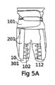
好ましい実施の形態では、柔軟な装着型筋肉補助装置が位置を変化させるかまたは維持することを補助する第1の身体部分は、四肢である。この場合、少なくとも2つのガーメント部分は、使用時に関節の概して遠位の位置を有する少なくとも1つのガーメント部分を有していてもよいのに対し、使用時の少なくとも1つの他方のガーメント部分は、関節の非遠位位置に設けられている。 In a preferred embodiment, the first body part that the flexible wearable muscle assist device assists in changing or maintaining position is a limb. In this case, the at least two garment parts may have at least one garment part having a location generally distal to the joint in use, while the at least one other garment part in use has a location generally distal to the joint. at a non-distal location.
身体部分が足または腕である場合、関節は、股関節または肩であってもよい。身体部分が腕であり、関節が肩である場合、使用時に関節の概して遠位の位置にある1つのガーメント部分は、上腕または前腕に配置されてもよい。身体部分が足であり、関節が股関節である場合、使用時に関節の概して遠位の位置にある1つのガーメント部分は、例えば、大腿に配置されていてもよい。両方の場合において、他方のガーメント部分は、使用者の胴に直接対面するように(したがって関節の非遠位に)配置されてもよい。 If the body part is a leg or an arm, the joint may be a hip joint or a shoulder. If the body part is an arm and the joint is a shoulder, one garment part, generally distal to the joint in use, may be placed on the upper arm or forearm. If the body part is a foot and the joint is a hip joint, one garment part that is generally distal to the joint in use may be placed on the thigh, for example. In both cases, the other garment part may be placed directly facing the user's torso (and thus non-distal to the joint).
その他の場合では、柔軟な装着型筋肉補助装置が、例えば、足を伸ばすのを補助するために使用され、したがって、第1の身体部分が、膝において第2の身体部分、すなわち大腿に連結された脛である場合、一方のガーメント部分は、足首、足先または脛自体に設けられてもよいのに対し、他方のガーメント部分は、膝の近位に設けられてもよく、すなわち大腿に対面している。 In other cases, flexible wearable muscle assist devices are used, for example, to assist in extending the leg, such that a first body part is connected to a second body part, i.e. the thigh, at the knee. In the case of a shin, one garment part may be provided at the ankle, toe or shin itself, whereas the other garment part may be provided proximal to the knee, i.e. facing the thigh. are doing.
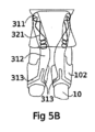
好ましい変形形態では、各受動的構成部材の部分が関節の一方の側、例えば、関節の前側にあるように、第1および第2の受動的構成部材が関節に沿って延びており、したがって、1つの動きは、第1の受動的構成部材を伸ばすのに対し、同じ動きが、例えば、関節の後側に配置された他方の受動的構成部材の伸びを減らす。したがって、第1および第2の構成部材の両方が、関節にトルクを加える。これは、可能な関節角度の全範囲にわたって当てはまる必要はなく、第1および第2の受動的構成部材が有していてもよい弾性材料のあらゆるプリテンションに依存する。第1および第2の構成部材のそれぞれによって可能な関節角度の全範囲にわたってトルクが加えられるように第2および第1の構成部材の両方にプリテンションが加えられていることが絶対に必要というわけではないことに留意すべきである。 In a preferred variant, the first and second passive components extend along the joint such that a portion of each passive component is on one side of the joint, for example on the anterior side of the joint, and thus: One movement stretches the first passive component, while the same movement reduces the stretching of the other passive component, for example located on the posterior side of the joint. Thus, both the first and second components apply torque to the joint. This need not be the case over the entire range of possible joint angles and depends on any pretensioning of the elastic material that the first and second passive components may have. It is imperative that both the second and first components be pretensioned so that the torque is applied over the full range of joint angles possible by each of the first and second components. It should be noted that this is not the case.
むしろ、第1または第2の受動的構成部材は、曲げ範囲の所定の部分にわたって、すなわち関節がほとんど完全に伸ばされたときまたは関節がほとんど完全に曲げられたとき、たるんでいることが可能である。 Rather, the first or second passive component can be slack over a predetermined portion of the bending range, i.e. when the joint is almost fully extended or when the joint is almost fully flexed. be.
しかしながら、可能な関節角度の範囲の少なくとも主要部分にわたって、第1および第2の構成部材の両方が同時に関節にトルクを加えると、一般に好ましい。例えば、第1および第2の受動的構成部材のうちの一方が曲げトルクを加えるのに対し、第2および第1および第2の構成部材のうちの他方が関節に伸ばしトルクを加えるように、両受動的構成部材にプリテンションがかけられていてもよい。この場合、第1および第2の受動的構成部材の全体トルクは、少なくとも全範囲にわたっては平衡せず、好ましい実施の形態では、1つの方向における正味トルクが関節に加えられる。 However, it is generally preferred if both the first and second components simultaneously apply torque to the joint over at least a major portion of the range of possible joint angles. For example, one of the first and second passive components applies a bending torque while the second and the other of the first and second components applies a stretching torque to the joint; Both passive components can also be pretensioned. In this case, the total torques of the first and second passive components are not balanced, at least over the entire range, and in preferred embodiments a net torque in one direction is applied to the joint.
典型的に、正味トルクは、正味関節曲げ補助のための2つの受動的構成部材によって提供される。これは、関節の伸ばしを補助するために柔軟な装着型筋肉補助装置の能動的構成部材が必要とされる大部分の患者にとって特に有益である。例えば、上腕が鉛直から水平へ持ち上げられるとき、腕と胴との間の肩関節が伸ばされる。同様の形式で、座っている人の膝は通常曲がっているのに対し、立ち上がることにより膝が伸び、したがって、椅子から立ち上がるのを補助するために、やはり関節の伸びが必要とされる。同じことが股関節にも当てはまり、股関節は、座った位置でより曲がっており、立っているときにより伸ばされる。また、人間が前傾し、直立するために補助を必要とする場合、背中の椎骨のラインも、いくぶん伸ばされる必要があることがある。次いで、歩行中、筋肉活動が損なわれた使用者の場合に予想される通常のゆっくりと歩行する足取りにおいて足先を地面から持ち上げることは、股関節および立っている足の膝の両方を、他方の足先の足底を地面から容易に離すことができるように十分にまっすぐにすることを必要とすることに留意されたい。したがって、歩行補助も、関節の伸びに依存する。上に与えられた行動は全てある身体部分を少なくとも僅かに持ち上げることに留意されるであろう。したがって、提供される補助は、反重力補助であると考えることができる。また、身体部分、例えば腕が装置の助けによって持ち上げられた位置に維持されるだけである場合、または例えば座っているときに人の傾倒が防止される場合にも、やはり反重力補助が提供される。 Typically, net torque is provided by two passive components for net joint bending assistance. This is particularly beneficial for most patients who require active components of a flexible wearable muscle assist device to assist in joint extension. For example, when the upper arm is lifted from vertical to horizontal, the shoulder joint between the arm and the torso is stretched. In a similar fashion, a sitting person's knees are normally bent, whereas standing up extends the knees, so extension of the joint is also required to assist in rising from a chair. The same applies to the hip joints, which are more flexed in the sitting position and more extended when standing. Also, if a person leans forward and requires assistance to stand upright, the vertebral lines of the back may also need to be stretched somewhat. Then, during walking, lifting the toe off the ground in the normal, slow walking gait that would be expected in a user with impaired muscle activity causes both the hip joint and the knee of the standing leg to Note that the sole of the foot needs to be straight enough so that it can be easily lifted off the ground. Therefore, walking assistance also depends on joint extension. It will be noted that the actions given above all raise some body part at least slightly. The assistance provided can therefore be thought of as anti-gravity assistance. Anti-gravity assistance is also provided if a body part, for example an arm, is only maintained in an elevated position with the help of a device, or if a person's leaning is prevented, for example when sitting. Ru.
上記のように、少なくとも1つの能動的構成部材が、関節の伸びを補助するように適応されていると有利である。これは、能動的構成部材が、その位置を変化させるために身体のある部分に力またはトルクを加える腱を有すると、容易に達成される。 As mentioned above, it is advantageous if at least one active component is adapted to assist in the extension of the joint. This is easily accomplished when the active component has a tendon that applies a force or torque to a part of the body to change its position.
腱は、通常、柔軟な装着型筋肉補助装置に沿って、アクチュエータから、力が加えられる点または領域まで案内され、アクチュエータは、通常、腱において引っ張るために使用される。第1および第2の受動的構成部材によって一緒に提供される正味補助が、関節の伸びのために少なくとも1つの能動的構成部材の腱が提供する力に対して拮抗するならば、特に好ましい。言い換えれば、能動的構成部材は最も頻繁に関節の伸びに対する補助を提供するのに対し、受動的構成部材の正味結果は、典型的に、能動的構成部材によって必要とされるように伸ばされた関節の曲げを提供する。 The tendon is typically guided along a flexible wearable muscle assist device from an actuator to the point or area where a force is applied, and the actuator is typically used to pull on the tendon. It is particularly preferred if the net assistance provided together by the first and second passive components counteracts the force provided by the tendons of the at least one active component for elongation of the joint. In other words, the active component most often provides assistance to joint extension, whereas the net result of the passive component is typically extended as required by the active component. Provides joint bending.
このように、単に能動的構成部材による補助を減らすことによってかつ/または身体部分が休息位置になるように能動的構成部材を完全に解放することによって、受動的構成部材は、拮抗力を提供するそれぞれの身体部分を再位置付けすることを助ける。 Thus, by simply reducing the assistance provided by the active component and/or by completely releasing the active component so that the body part is in the rest position, the passive component provides an opposing force. Helps reposition each body part.
身体部分を所与の水平位置に位置付けることを助けるために、本発明の柔軟な装着型筋肉補助装置を使用することができる。例えば、使用者が腕を持ち上げることができるとしても、それにもかかわらず、体の横で水平位置から体の正面へ腕を動かすことができない可能性がある。このような動きに障害がある場合、本発明の柔軟な装着型筋肉補助装置が、説明した運動を補助してもよい。 The flexible wearable muscle assist device of the present invention can be used to assist in positioning a body part in a given horizontal position. For example, even if a user is able to lift their arm, they may nevertheless be unable to move it from a horizontal position next to their body to in front of their body. If such movements are impaired, the flexible wearable muscle assist device of the present invention may assist in the movements described.
しかしながら、ほとんどの場合、使用者は、腕を持ち上げる、座った位置から立ち上がるまたは歩き始めるために十分に体をまっすぐにするときに問題を有することが予想される。これらの典型的な場合、筋肉は、重力に逆らって身体または身体部分を持ち上げるためには弱すぎ、したがって、柔軟な装着型筋肉補助装置が、重力に逆らって身体部分の位置を変化させることを補助するために使用される。しかしながら、問題は、重力に逆らって身体部分を持ち上げる際に存在するだけでなく、重力があるにもかかわらず身体部分の位置を維持する際にも存在する。 However, in most cases, users are expected to have problems lifting their arms, standing up from a sitting position, or straightening their bodies enough to begin walking. In these typical cases, the muscles are too weak to lift the body or body part against gravity, and therefore a flexible wearable muscle assist device is used to change the position of the body part against gravity. used to assist. However, problems exist not only in lifting the body part against gravity, but also in maintaining the position of the body part despite the presence of gravity.
例えば、使用者が髪をとかそうとするとき、使用者は、通常、腕を持ち上げて、髪をとかしている間、持ち上げられた位置に腕を維持する必要がある。これは、健康な使用者にとっては大きな問題にならないが、筋肉の弱い人間にとってはあまりに困難であることがある。したがって、好ましい実施の形態における柔軟な装着型筋肉補助装置は、重力に逆らって所与のまたは特定の位置に身体部分を支持するように適応されていてもよい。 For example, when a user attempts to comb their hair, the user typically needs to lift their arm and maintain the arm in an elevated position while combing the hair. While this is not a major problem for healthy users, it may be too difficult for people with weak muscles. Accordingly, a flexible wearable muscle assist device in a preferred embodiment may be adapted to support a body part in a given or specific position against gravity.
重力に逆らって第1の身体部分の位置を維持するために、重力に逆らって第1の身体部分の位置を変化させることを補助するように適応された、案内される腱および腱のためのアクチュエータを有する本発明の柔軟な装着型筋肉補助装置が使用されてもよいことが理解されるであろう。この場合、停止している間、腱の長さを維持するためにアクチュエータの動きを単に停止させることができる。 for guided tendons and tendons adapted to assist in changing the position of the first body part against gravity to maintain the position of the first body part against gravity; It will be appreciated that the flexible wearable muscle assist device of the present invention having an actuator may be used. In this case, the movement of the actuator can simply be stopped to maintain the length of the tendon during the stop.
アクチュエータを停止させることは、例えばさらなる動きに対する機械的ロックである受動的手段によって、またはモータに連続的な動力を加えることによって、行われてもよい。 Stopping the actuator may be done by passive means, for example a mechanical lock against further movement, or by applying continuous power to the motor.
非常に好ましい実施の形態では、アクチュエータは、案内された腱を巻き上げ、腱は、腱を巻き上げることが少なくとも1つの関節を伸ばすような形式で案内される。これにより、アクチュエータとして、回転軸を有する単純なモータを使用することができる。この場合、能動的構成部材が作動したときに関節を曲げるために使用される腱が繰り出されると、力は、関節において連結された身体部分、および/または付加的な身体部分の重量の少なくとも1つによって、かつ/または、第1および第2の受動的構成部材の共通の動作によって正味トルクとして提供される関節上のトルクの非ゼロ合計によって、腱に加えられる。 In a highly preferred embodiment, the actuator rolls up the guided tendon, and the tendon is guided in such a way that rolling up the tendon stretches the at least one joint. Thereby, a simple motor with a rotating shaft can be used as the actuator. In this case, when the tendons used to bend the joint are paid out when the active component is actuated, the force is at least one part of the weight of the body parts connected at the joint, and/or of the additional body parts. and/or by a non-zero sum of torques on the joint provided as a net torque by the common motion of the first and second passive components.
腱は、例えば使用者が座るとき、制御された形式で繰り出されてもよい。ここで、腱の張力がゆっくりと減らされ、腱がゆっくりと繰り出されて、使用者が椅子の上で突然倒れることを防止する。また、関節の伸ばしのみが能動的にサポートされるが、両方向の動き、すなわち関節の曲げおよび伸ばしが、使用者によって受け入れられるように十分に速くなることが理解されるであろう。 The tendon may be deployed in a controlled manner, for example when the user sits down. Here, the tension in the tendon is slowly reduced and the tendon is slowly rolled out to prevent the user from suddenly collapsing on the chair. It will also be appreciated that although only joint extension is actively supported, movement in both directions, i.e. joint bending and extension, will be fast enough to be accepted by the user.
複数の腱に分割された腱を有することも可能である。これにより、例えば、膝を伸ばすために1つの腱のみを巻き上げるが、膝に沿った2つの部分、すなわち膝関節の左側に沿った第1の部分および膝関節の右側に沿った他方の腱部分において腱を案内することが必要である。これは、例えば、肘についても行うことができる。 It is also possible to have the tendon divided into multiple tendons. This allows, for example, to roll up only one tendon to extend the knee, but two parts along the knee: the first part along the left side of the knee joint and the other tendon part along the right side of the knee joint. It is necessary to guide the tendon at the point. This can also be done, for example, for the elbows.
言い換えれば、少なくとも1つの能動的構成部材は、矢状面から見て体の一方の側で案内されかつ前額面の互いに反対側へ案内される2つの部分に分離した少なくとも1つの腱を有する。 In other words, the at least one active component has at least one tendon separated into two parts guided on one side of the body in the sagittal plane and guided on opposite sides of the coronal plane.
腱は、ボディインターフェースに取り付けられてもよく、例えば、人間の足先の一部の周囲に配置されたループを形成するように再統合されていてもよいし、または、例えば膝を通過して腱を足先、足首または脛に取り付けることができるようにするために矢状面の反対側へ再び方向付けられていてさえよい。 The tendon may be attached to the body interface, for example, reintegrated to form a loop placed around part of the toe of a human foot, or may be re-integrated, for example through the knee. It may even be reoriented to the opposite side of the sagittal plane to allow the tendon to be attached to the toe, ankle or shin.
特に関節に到達する前に分割され、次いで、関節のそれぞれの側において関節に沿って案内されるように、腱を複数の腱端部に枝分かれさせることによって、関節自体における圧力が減少し、また、配置も機械的安定性に関してより安定する。 In particular, by branching the tendon into multiple tendon ends that are split before reaching the joint and then guided along the joint on each side of the joint, pressure at the joint itself is reduced and , the arrangement is also more stable in terms of mechanical stability.
関節よりも少ないアクティベータを使用する形式において複数の関節角度の同時調節を要求する動きをサポートするために、柔軟な装着型筋肉補助装置を適応させることができることに留意すべきである。例えば、股関節および膝の両方を伸ばすために単一のアクチュエータを使用することができる。アクチュエータの数を減らすと、柔軟な装着型筋肉補助装置のコスト、重量および複雑さが減り、より多数の使用者が、本発明の柔軟な装着型筋肉補助装置をより頻繁に使用することにつながることが理解されるであろう。 It should be noted that flexible wearable muscle assist devices can be adapted to support movements that require simultaneous adjustment of multiple joint angles in a format that uses fewer activators than joints. For example, a single actuator can be used to extend both the hip and knee. Reducing the number of actuators reduces the cost, weight, and complexity of the flexible wearable muscle assist device, leading to a greater number of users and more frequent use of the flexible wearable muscle assist device of the present invention. That will be understood.
したがって、本発明による柔軟な装着型筋肉補助装置が、足の位置の変化を補助するかまたは足の位置を維持するように適応されると好ましい。腱が、概して膝の前側であるが、概して股関節の後側の背後で案内される場合、受動的エレメントとしてのストレッチバンドを膝の背後に設けることができ、股関節のための受動的エレメントとしてのストレッチバンドを、人間の前側に設けることができる。これに関して、受動的エレメントとしてのストレッチバンドを提供することは絶対に必要というわけではないが、受動的エレメントは、例えば、伸長可能なストリングを含むこともできることに留意すべきである。 It is therefore preferred that the flexible wearable muscle assist device according to the invention is adapted to assist in changing or maintaining the position of the foot. If the tendon is guided generally on the front side of the knee, but generally behind the back side of the hip joint, a stretch band as a passive element can be provided behind the knee, and a stretch band as a passive element for the hip joint can be provided. A stretch band can be placed on the front side of the person. In this regard, it should be noted that it is not absolutely necessary to provide a stretch band as a passive element, but the passive element can also include, for example, a stretchable string.
しかしながら、幅広のバンドが好ましい。なぜならば、幅広のバンドが装置ひいては使用者の体に対して加える圧力がより均一に分散し、また、例えば使用者が座る場合、幅広のバンドはより快適であるからである。典型的な幅広のバンドは、1cm~10cm、好ましくは2.5cm~7cmの幅を有していてもよい。 However, wide bands are preferred. This is because a wider band distributes the pressure it exerts on the device and thus on the user's body more evenly, and is also more comfortable, for example when the user is sitting down. A typical wide band may have a width of 1 cm to 10 cm, preferably 2.5 cm to 7 cm.
最も好適な場合では、柔軟な装着型筋肉補助装置は、腕または足の位置を変化させるかまたは維持する筋肉に補助を提供する。これらの場合、補助される四肢は、長手方向軸線を有する。腱は、最も頻繁に、胴のどこか(または、より正確には、胴に配置されたベース層)に取り付けられる。このような場合、腱は、四肢の対応する部分の長手方向軸線の主方向に沿って延びており、腱を巻き込むときに腱が四肢に対して移動しなければならない場合、腱はこの方向に滑る。 In the most preferred case, the flexible wearable muscle assist device provides assistance to the muscles that change or maintain the position of the arm or leg. In these cases, the limb being assisted has a longitudinal axis. Tendons are most often attached somewhere on the torso (or, more precisely, to a base layer located on the torso). In such cases, the tendon extends along the main direction of the longitudinal axis of the corresponding part of the limb, and if the tendon has to move relative to the limb when wrapping the tendon, the tendon will move in this direction. slide.
エネルギを蓄えるための弾性材料を含む第1および第2の受動的構成部材は、ストレッチバンドを含んでもよいし、かつ/または、使用時にボディインターフェースに取り付けられるストレッチバンドによって構成されていてもよい。第1および第2の受動的構成部材のためにストレッチバンドを使用すると、上記で説明したのと同じ利点を提供するが、ばね、伸長可能なストリングなどが使用されてもよいことが当業者によって理解されるであろう。 The first and second passive components including elastic materials for storing energy may include and/or be configured by stretch bands that are attached to the body interface during use. It will be appreciated by those skilled in the art that the use of stretch bands for the first and second passive components provides the same advantages as described above, but that springs, stretchable strings, etc. may also be used. It will be understood.
本発明の柔軟な装着型筋肉補助装置の非常に好ましい変形形態では、柔軟な装着型筋肉補助装置を使用するときに使用者が受ける組織に対するせん断を減らすために注意が払われる。せん断に関して、能動的構成部材の腱は、いくつかの条件下で、人体またはより正確にはボディインターフェースに加えられる必要がある引張力を加えることに留意されたい。骨格により近い、四肢またはその他の身体部分の内側部分は、通常、このような外力によって影響されにくく、すなわち、内側部分はより動かず、その結果、力が皮膚に加えられると、人体の内側部分に対する人体の外側部分の運動が生じることがあることに留意されたい。これは、せん断と呼ばれ、本発明の柔軟な装着型筋肉補助装置を使用する際の快適性が、この効果の影響を受けることがあることが理解されるであろう。 In a highly preferred variation of the flexible wearable muscle assist device of the present invention, care is taken to reduce the shear to tissue experienced by the user when using the flexible wearable muscle assist device. Regarding shear, it should be noted that the tendons of active components under some conditions exert tensile forces that need to be applied to the human body or more precisely the body interface. The inner part of a limb or other body part, which is closer to the skeleton, is usually less affected by such external forces, i.e. the inner part is more stationary, so that when a force is applied to the skin, the inner part of the human body It should be noted that movements of the outer parts of the human body may occur. This is called shearing, and it will be appreciated that the comfort when using the flexible wearable muscle assist device of the present invention may be affected by this effect.
したがって、あらゆる柔軟な装着型筋肉補助装置において、せん断の効果を減らすことが好ましい。本発明は、体の関節の互いに反対側に配置されかつ少なくとも2つのガーメント構成部材の間に延びる第1および第2の受動的構成部材を有する最も一般的な形式でさえも、体の様々な異なる部分に力を加える、例えば、関節の複数の側に引張力を加えるという有利な効果を有する。本発明の好ましい実施の形態では、第1および第2の受動的構成部材によって加えられる力またはトルクが互いに異なるとしても、このことは、関節の近くにおける力の全体的なより均一な配分に寄与し、したがって、せん断による使用者の不快な体験を減らす。加えて、ガーメント部分のうちの少なくとも一方が四肢の少なくとも一部を包囲していると好ましい。 Therefore, it is desirable to reduce the effects of shear in any flexible wearable muscle assist device. The present invention is useful for various body joints, even in its most general form having first and second passive components located on opposite sides of a body joint and extending between at least two garment components. It has the advantageous effect of applying forces to different parts, for example applying tensile forces on multiple sides of a joint. In a preferred embodiment of the invention, even though the forces or torques applied by the first and second passive components are different from each other, this contributes to an overall more uniform distribution of forces in the vicinity of the joint. and thus reduce the user's unpleasant experience due to shearing. Additionally, it is preferred if at least one of the garment parts surrounds at least part of the limb.
したがって、好ましい実施の形態では、それぞれのガーメント部分を収縮させる収縮エレメントが設けられていてもよい。ガーメント部分は、四肢部分を完全に包囲する必要はなく、例えば、その一部のみをカバーしてもよい。四肢周囲の一部をカバーしないでおくことにより、より多くの蒸散が許容され、特定の医学的検査などが可能になり、柔軟な装着型筋肉補助装置の装着がより容易になる。しかしながら、力の配分がより不均一になることがあり、これはせん断を生じる。 Accordingly, in a preferred embodiment, a contraction element may be provided for contracting the respective garment part. The garment portion need not completely surround the limb portion, but may, for example, cover only a portion thereof. Leaving a portion of the limb circumference uncovered allows for more transpiration, allows for certain medical tests, etc., and makes it easier to attach flexible wearable muscle assist devices. However, the force distribution may become more uneven, which results in shear.
重なり合ったガーメントの領域において、フック・アンド・パイルファスナ、例えばベルクロファスナを用いて、ガーメント部分によって四肢の全周をカバーすることができる。ガーメント部分の少なくとも一方が、四肢の一部を少なくとも部分的に、例えば周囲の半分以上、好ましくは周囲の少なくとも3分の2を包囲していると、四肢の周囲にガーメント部分のフィットを締め付ける収縮エレメントを提供することができる。これは、せん断などの不利な効果をさらに一層均一化する。 In the area of the overlapping garment, hook-and-pile fasteners, such as Velcro fasteners, can be used to cover the entire circumference of the limb by the garment portion. at least one of the garment parts at least partially surrounds a portion of the limb, such as more than half the circumference, preferably at least two-thirds of the circumference, and contraction tightening the fit of the garment part around the limb; elements can be provided. This evens out adverse effects such as shearing even further.
基本的に、いったん使用者が柔軟な装着型筋肉補助装置を装着すると、収縮エレメントを単に緊張させることができる。これは、ある程度まで行うことができる。しかしながら、収縮エレメントが強すぎると、せん断がないとしても使用者にとって不快であり、四肢を通る血流も制限される。これは、使用者の感覚機能に障害がある場合、および/または、使用者が不快感を伝達することができないか柔軟な装着型筋肉補助装置を自分自身で調節することができない場合に、特に深刻である。 Basically, once the user has donned the flexible wearable muscle assist device, the contractile element can simply be tensioned. This can be done to some extent. However, if the constriction element is too strong, even in the absence of shear, it will be uncomfortable for the user and will also restrict blood flow through the limb. This is especially true if the user's sensory function is impaired and/or if the user is unable to communicate discomfort or adjust the flexible wearable muscle assist device themselves. It's serious.
したがって、特に好ましい実施の形態では、収縮エレメントが、このような不利な効果を減らすための形式で設計されることが非常に好ましい。このために、収縮エレメントを、特に織物の一体的部分として、ガーメント部分自体に埋め込むことができる。収縮エレメントは、受動力構成部材に取外し可能または固定的に接続することができ、これにより、受動力構成部材によって加えられる力が増大すると、四肢の周囲に収縮エレメントを締め付けることができる。また、収縮エレメントを能動的腱または能動的構成部材の一部に接続することができる。 Therefore, in particularly preferred embodiments, it is highly preferred that the contraction element is designed in a manner to reduce such adverse effects. For this purpose, the shrink element can be embedded in the garment part itself, in particular as an integral part of the fabric. The contraction element can be removably or fixedly connected to the passive force component such that increasing force exerted by the passive force component can tighten the contraction element about the limb. Also, the contraction element can be connected to an active tendon or part of an active component.
上記のことから、能動的構成部材の腱が四肢の長手方向軸線に沿って延びている好ましい実施の形態では、収縮エレメントは、使用時にガーメント部分の位置を維持するために四肢の長手方向軸線に対して略垂直に向けられてもよいことが理解されるであろう。収縮エレメントがあるレベルまでプリテンションをかけられていてもよく、収縮エレメントとしてバックル状ベルトを使用することができることにも留意すべきである。 From the above, it will be appreciated that in preferred embodiments where the tendon of the active component extends along the longitudinal axis of the limb, the retractable element extends along the longitudinal axis of the limb to maintain the position of the garment portion during use. It will be appreciated that it may also be oriented substantially perpendicular to the surface. It should also be noted that the contraction element may be pretensioned to a certain level and that a buckle-like belt can be used as the contraction element.
したがって、使用者のためのせん断の不利な効果を減らすための他の可能性が存在することに留意されたい。これらの他の可能性は、上述の提案に加えて使用することができ、かつ/またはそれとは別個に使用することができる。 It should therefore be noted that other possibilities exist to reduce the adverse effects of shear for the user. These other possibilities can be used in addition to and/or separately from the above-mentioned suggestions.
好ましい実施の形態では、使用者の身体と腱との間に滑りプレートが設けられてもよいことに留意されたい。これは、腱の摩擦を減らし、摩耗および熱発生によって生じる不快感を減らし、腱によって生じる圧力を均一化する。特に、靴紐と同様に、腱において引っ張ることが、滑りプレート上で可動なガーメント部分またはエレメントの2つの端部を引き寄せるように、能動的腱を少なくともその長さの一部にわたってジグザグパターンに沿って案内することができ、これは、四肢の周囲にガーメントを締め付けることを助ける。 Note that in preferred embodiments a sliding plate may be provided between the user's body and the tendon. This reduces tendon friction, reduces discomfort caused by wear and heat generation, and equalizes the pressure created by the tendons. In particular, similar to a shoelace, the active tendon is moved along a zigzag pattern over at least part of its length so that a pull on the tendon draws the two ends of the garment part or element movable on the sliding plate. This helps tighten the garment around the limb.
柔軟な装着型筋肉補助装置は、通常、装置がより柔軟であるほどより快適であると考えられることに留意すべきである。例えば、使用者がリラックスした位置におり、体の僅かな動きしか生じず、補助なしで動くことができるとき、装着型筋肉補助装置は、できるだけ柔軟であるべきである。これに対して、使用者の補助が必要なとき、装置は、補助に支障があるほど柔軟であってはならない。 It should be noted that flexible wearable muscle assist devices are generally considered to be more comfortable the more flexible the device. For example, the wearable muscle assist device should be as flexible as possible when the user is in a relaxed position, making only small movements of the body and able to move without assistance. On the other hand, when user assistance is required, the device must not be so flexible that it interferes with assistance.
したがって、柔軟な装着型筋肉補助装置の剛性または柔軟性は、装置の現在の使用状態に依存することが非常に好ましい。 Therefore, it is highly preferred that the stiffness or flexibility of the flexible wearable muscle assist device depends on the current state of use of the device.
また、柔軟な装着型筋肉補助装置の少なくとも一部の全体的な剛性が、時間の経過とともに変化することができると、非常に好ましい。これは、例えば、好ましい実施の形態では、全体的な剛性を変化させるように一緒に適応された複数の層またはプライを有するボディインターフェースによって達成することができる。複数プライ配置が、互いに対して滑るプライを有していると、ボディインターフェースは、かなり低い剛性を有する柔軟な印象を与える。これに対して、プライが、互いに強い相互作用を有する場合、すなわち互いに付着または粘着していたり、互いに強く引き付けられていたり、互いに面した粗い面を有しているなどの場合、プライを独立して曲げるまたは変形させることはできず、全体的な剛性は著しく高くなる。 It is also highly preferred if the overall stiffness of at least a portion of the flexible wearable muscle assist device is capable of changing over time. This can be achieved, for example, in a preferred embodiment by a body interface having multiple layers or plies adapted together to vary the overall stiffness. When a multi-ply arrangement has plies that slide relative to each other, the body interface gives the impression of being flexible with significantly lower stiffness. On the other hand, if the plies have strong interactions with each other, such as sticking or sticking to each other, being strongly attracted to each other, or having rough surfaces facing each other, the plies can be separated. It cannot be bent or deformed, and the overall stiffness is significantly higher.
いわゆる層ジャミングを誘発することができることに留意すべきである(慣用的な技術用語である「層」を使用しているが、ボディインターフェースは、層ではなくプライを有すると考えられてもよい)。 It should be noted that so-called layer jamming can be induced (although we use the conventional technical term "layer", the body interface may be considered to have plies rather than layers). .
柔軟な装着型筋肉補助装置の少なくとも一部の全体的な剛性を変化させることができる複数の層に加えてかつ/またはこれに代えて、ボディインターフェースは、特に能動的腱が引っ張られるときにまたは腱が巻き取られるときに引張力が加えられると、自動的に締め付けるように適応された、1つまたは複数の収縮エレメントを有することができる。 In addition to and/or in lieu of multiple layers that can vary the overall stiffness of at least a portion of the flexible wearable muscle assist device, the body interface may include It may have one or more contraction elements adapted to automatically tighten when a tension force is applied as the tendon is wound.
また、ボディインターフェースに1つまたは複数のプレート、特に異方性プレートが設けられている場合、これは、せん断力を法線力に変換するためにも使用することができ、身体部分を位置付けることを助ける、すなわち典型的に関節を伸ばすことを助ける方向で有効な力を加えるときに、せん断力を減らすことができることに留意すべきである。 In addition, if the body interface is provided with one or more plates, especially anisotropic plates, this can also be used to convert shear forces into normal forces and to position body parts. It should be noted that shear forces can be reduced when applying an effective force in a direction that helps the joint, i.e. typically helps extend the joint.
弾性材料を有しかつエネルギを蓄える受動的構成部材は、股関節、足首関節、肩および/または肘のうちの少なくとも1つの近くに配置されてもよいことに留意すべきである。これらの弾性材料は、例えば身体部分の以前の移動の間に、例えば関連する関節の曲げのために、プリテンションをかけることができる。次いで、本発明の柔軟な装着型筋肉補助装置を装着する使用者によって補助が要求されたとき、例えば、関節を伸ばす間、弾性材料は、身体に対して仕事を行ってもよい。 It should be noted that the passive component having elastic material and storing energy may be placed near at least one of the hip joint, ankle joint, shoulder and/or elbow. These elastic materials can be pretensioned, eg during previous movement of the body part, eg due to bending of the joint involved. The elastic material may then perform work on the body when assistance is requested by a user wearing the flexible wearable muscle assist device of the present invention, for example, while extending a joint.
重力に逆らって身体部分を位置付ける際に使用者を補助しながらエネルギを解放することは、関連する足または腕の重量を補償することを助け、装置のエネルギ消費を減らしまたは特に大きな電池を提供する必要性を減らし、電気回路および/または電気モータなどにおける熱負荷を減らす。 Releasing energy while assisting the user in positioning body parts against gravity helps compensate for the weight of the legs or arms involved, reducing the energy consumption of the device or providing a particularly large battery. reducing the need for and heat load on electrical circuits and/or electric motors, etc.
少なくとも幾つかの能動的構成部材は、通常、その自重または別の連結された身体部分の重量に逆らって身体部分を動かすかまたは維持する筋肉を補助するために配置されることに留意すべきである。例えば、上腕を持ち上げるために補助が提供される場合、手および前腕の付加的な重量を考慮する必要があることがある。 It should be noted that at least some active components are typically arranged to assist muscles in moving or maintaining a body part against its own weight or the weight of another connected body part. be. For example, if assistance is provided to lift the upper arm, the additional weight of the hand and forearm may need to be considered.
上述したように、柔軟な装着型筋肉補助装置の使用は、第1の身体部分が1つの関節のみを介して第2の身体部分に直接的に連結されている場合に制限されない。例えば、下腿を動かす筋肉群が特に弱いために、脛または下腿の動きに大きな補助が与えられる必要がある場合、本発明の柔軟な装着型筋肉補助装置の使用者が、下腿の位置および大腿の位置の両方を変化させるかまたは維持することを助けることがさらに有用かつ合理的であることがある。 As mentioned above, the use of flexible wearable muscle assist devices is not limited to cases where a first body part is directly connected to a second body part via only one joint. For example, if the muscle groups that move the lower leg are particularly weak and the movement of the shin or lower leg needs to be given greater assistance, the user of the flexible wearable muscle assist device of the present invention may It may be further useful and reasonable to help both change or maintain position.
能動的構成部材が、膝および股関節の両方の角度位置を変化させるかまたは維持するようにも適応されている場合、1つのアクチュエータのみを使用することが好ましい。下腿だけのために補助を必要とする患者の第1のグループと、下腿および大腿の両方を動かすために補助を必要とする使用者の第2のグループのために、同じ柔軟な装着型筋肉補助装置を使用することができる。 If the active component is also adapted to change or maintain the angular position of both the knee and hip joint, it is preferred to use only one actuator. The same flexible wearable muscle aid for a first group of patients who require assistance for the lower leg only and a second group of users who require assistance to move both the lower leg and thigh. equipment can be used.
非常に好ましい実施の形態では、腱は、1つまたは複数の低摩擦シース内に案内されており、そのうちの少なくとも幾つかは、ガーメント部分のうちの少なくとも1つに部分的に取り付けられている。言い換えれば、シースは、腱が延びている場所を規定する形式でガーメント部分に固定される。したがって、シースをガーメント部分に接続することによって、エクソスーツまたは本発明の柔軟な装着型筋肉補助装置を装着することがより容易になる。また、腱は、正しい場所に容易にとどまる。 In a highly preferred embodiment, the tendon is guided within one or more low friction sheaths, at least some of which are partially attached to at least one of the garment parts. In other words, the sheath is secured to the garment portion in a manner that defines where the tendon extends. Thus, connecting the sheath to the garment portion makes it easier to wear the exosuit or flexible wearable muscle assist device of the present invention. Also, the tendon stays in place easily.
非常に好ましい実施の形態では、腱は、たるんだシース内に案内されており、そのうちの少なくとも幾つかは、好ましくは、ガーメント部分のうちの少なくとも1つに少なくとも部分的に取り付けられている。たるんだシースを使用することができる。なぜならば、腱は引っ張られる必要があるだけであり、アクチュエータから、動かされる身体部分における終点まで押付力が伝達される必要がないからである。 In a highly preferred embodiment, the tendons are guided within a slack sheath, at least some of which are preferably at least partially attached to at least one of the garment parts. A slack sheath can be used. This is because the tendon only needs to be pulled and no pushing force needs to be transmitted from the actuator to its end point in the body part to be moved.
言い換えれば、他のエクソスーツのために一般的なボーデン(bowden)ケーブルを使用する必要がない。このようなボーデンケーブルは剛体であり、したがって、通常は不快感の原因である。一方向にのみ、すなわち引っ張ることによって補助を提供する腱の使用は、特に能動的構成部材および受動的構成部材の両方を提供することによって可能であり、好ましい実施の形態における受動的構成部材は、作動した腱の効果に対して拮抗する力を提供することができる。 In other words, there is no need to use the common bowden cables for other exosuits. Such Bowden cables are rigid and are therefore usually a source of discomfort. The use of tendons that provide assistance in only one direction, i.e. by pulling, is possible in particular by providing both active and passive components, the passive components in preferred embodiments being A force can be provided that counteracts the effect of the actuated tendon.
アクチュエータのうちの少なくとも1つのためにおよび/または少なくとも1つのアクチュエータのための電池のために剛体のキャリヤプレートを提供することが可能であり、かつ好ましい。アクチュエータおよび電池の双方は、かなり重く、本発明の柔軟な装着型筋肉補助装置のガーメントまたはその他の部分よりも高い密度を有している。したがって、重量および使用者の身体に対するあらゆる圧力が、好ましい配置で大きな面積にわたって均一に配分されるべきである。これは、前述のキャリヤプレートを使用して達成することができる。 It is possible and preferred to provide a rigid carrier plate for at least one of the actuators and/or for the battery for the at least one actuator. Both the actuator and battery are considerably heavier and have a higher density than the garment or other parts of the flexible wearable muscle assist device of the present invention. Therefore, the weight and any pressure on the user's body should be evenly distributed over a large area in the preferred arrangement. This can be achieved using the carrier plate described above.
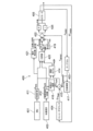
非常に好ましい実施の形態では、アクチュエータは、電気モータである。電気モータの使用は、重量およびコストを節約する。好ましい実施の形態では、センサ配列から導き出される信号に応答して1つまたは複数のアクチュエータを作動させるために配置された1つのアクチュエータ制御装置が設けられている。このセンサ配列は、第1の身体部分と第2の身体部分との間に存在する関節の角度の少なくとも1つを示す信号を生成するように適応されている。第1の身体部分と第2の身体部分との間に2つ以上の関節が存在する場合、複数の関節または各関節の角度が求められてもよい。さらに、関節の絶対角度または絶対角度の変化を測定することができる。さらに、第1の身体部分の絶対移動および/または第2の身体部分に対する第1の身体部分の動きを測定することができる。第2の身体部分に対する第1の身体部分の動きが測定される場合、複数のセンサを提供することが必要または有用であることがあり、少なくとも1つのセンサが第1の身体部分に設けられ、別のセンサが第2の身体部分に設けられることが理解されるであろう。 In a highly preferred embodiment, the actuator is an electric motor. The use of electric motors saves weight and cost. In a preferred embodiment, an actuator controller is provided which is arranged to actuate one or more actuators in response to signals derived from the sensor array. The sensor array is adapted to generate a signal indicative of at least one joint angle existing between the first body part and the second body part. If more than one joint exists between the first body part and the second body part, the angle of the plurality of joints or each joint may be determined. Additionally, the absolute angle or change in absolute angle of the joint can be measured. Furthermore, the absolute movement of the first body part and/or the movement of the first body part relative to the second body part can be measured. When movement of the first body part relative to the second body part is measured, it may be necessary or useful to provide a plurality of sensors, at least one sensor being provided on the first body part; It will be appreciated that another sensor is provided on the second body part.
また、単に第1の(補助される)身体部分の動きを測定するのではなく、例えば、使用者の体幹が揺れ動いているか否かを検出するために、他の身体部分の動きからアクチュエータの制御のための信号を導き出すことが可能であってもよい。 In addition, rather than simply measuring the movement of the first (assisted) body part, it is also possible to use It may be possible to derive signals for control.
次いで、動きまたは位置の両方に関連した身体の部分における圧力および/または第1の身体部分の位置を検出することができる。例えば、本発明の柔軟な装着型筋肉補助装置が、歩行しているときに使用者を補助するために機能する場合、足底における圧力配分が検出されてもよい。これは、足が現在地面から持ち上げられているか否か、一定の圧力が観察されるか否か、使用者が静止状態で立っていることを示す一定の圧力または一定圧力配分、を特定するために用いることができる。 Pressure on the body part and/or position of the first body part can then be detected both in relation to movement or position. For example, when the flexible wearable muscle assist device of the present invention functions to assist a user while walking, pressure distribution on the sole of the foot may be detected. This is to determine whether the foot is currently lifted off the ground, whether a constant pressure is observed, a constant pressure or a constant pressure distribution indicating that the user is standing still. It can be used for.
一方または両方の足底における全体圧力の測定を導き出すことができる場合、所定の使用者が足を地面に着いているか否か、使用者が座っているか否か、または使用者が立っているか否かを区別することができる。 If it is possible to derive a measurement of the overall pressure at one or both soles, it is possible to determine whether a given user has their feet on the ground, whether the user is sitting or not, or whether the user is standing. can be distinguished.
また、圧力配分を特定することおよび/または圧力があるしきい値を超えていることを特定することで、立ち上がる、座る、立っているまたは歩行しているときの特定の段階を識別しかつ区別することができる。 It also identifies and differentiates specific phases when standing up, sitting down, standing or walking by identifying the pressure distribution and/or identifying when the pressure exceeds a certain threshold. can do.
特に好ましい実施の形態では、柔軟な装着型筋肉補助装置が、足を地面から持ち上げることを補助する形式で歩行を補助するために使用される場合、足を地面から持ち上げるための補助は、好ましくは、他方の足が地面に十分にしっかりと接触していることが決定された場合にのみ提供されることに留意されたい。これは、センサ信号の解釈が困難であり、使用者が転倒する、座っているときに椅子の上で倒れることなどを防止するために、アクチュエータを作動させかつ/または解放する前に、使用者の現在の姿勢の明らかな理解が得られなければならない場合に特に有用である。 In a particularly preferred embodiment, when the flexible wearable muscle assist device is used to assist walking in the form of an aid to lifting the foot off the ground, the aid for lifting the foot off the ground is preferably , is provided only if it is determined that the other foot is in sufficiently firm contact with the ground. This is because the sensor signals are difficult to interpret and the user has to wait before actuating and/or releasing the actuator to prevent the user from falling, falling over the chair while sitting, etc. This is particularly useful when a clear understanding of the current posture of a person must be obtained.
様々な異なる身体部分、様々な異なるパラメータなどに関する様々な異なるセンサ信号を生成する複数のセンサを含むセンサ配列が、姿勢を特定し、これにより、アクチュエータを適切な形式で制御するために有用であり得ることが理解されるであろう。 Sensor arrays including multiple sensors that generate a variety of different sensor signals for various different body parts, various different parameters, etc. are useful for determining posture and thereby controlling actuators in an appropriate manner. You will understand what you get.
センサ配列が、複数のセンサを有しかつさらに対応する信号調整回路および1つまたは複数のアナログ/デジタル変換器を有する場合、アクチュエータ制御は、例えばマイクロコントローラ配列のためのソフトウェアとしてのデジタル回路を使用して実施することができる。 If the sensor array has a plurality of sensors and also has a corresponding signal conditioning circuit and one or more analog/digital converters, the actuator control uses digital circuits, for example as software for the microcontroller array. It can be implemented by
センサ配列は、センサアレイであると解釈しかつ理解することができるが、センサを正確なコラム、列などに配置する必要はないことが当業者によって理解されるであろう。 Although a sensor array can be interpreted and understood to be a sensor array, it will be understood by those skilled in the art that the sensors need not be arranged in precise columns, rows, etc.
また、複数の異なるセンサ、例えば、モーションセンサ、3軸加速度計および慣性測定ユニット(IMU)のグループからの異なるエレメントのうちの少なくとも2つを有するセンサ配列を使用することができる。 It is also possible to use a sensor array having at least two of a plurality of different sensors, for example different elements from the group of motion sensors, three-axis accelerometers and inertial measurement units (IMUs).
センサは、再現性のある条件下で良好な信号対ノイズ比を生じるが、柔軟な装着型筋肉補助装置が柔軟であり、かつセンサがスーツの柔軟な、したがって動く部分に取り付けられていることに部分的に起因して、使用者の現在の位置または姿勢を特定するときの大きな不確実性が残る場合があることが理解される。したがって、あらゆるセンサ測定が不利に影響される可能性が存在し、ゆえにこのようなばらつきを修正するために注意が払われなければならない。それにもかかわらず、スーツは、日常生活の様々な仕事および活動のために使用されると特に好ましく、したがって、制御回路は、好ましくは、所与のストライド、スタンス、姿勢などを特定し、センサ信号に応答して、高い確実性で歩行中のスタンスまたはスイング段階を特定するように適応されている。 Although the sensor yields a good signal-to-noise ratio under reproducible conditions, it is important that the flexible wearable muscle assist device is flexible and that the sensor is attached to a flexible and therefore moving part of the suit. It is understood that, in part due to this, there may remain a large degree of uncertainty in determining the current position or posture of the user. Therefore, there is a possibility that any sensor measurements will be adversely affected and therefore care must be taken to correct for such variations. Nevertheless, the suit is particularly preferred when used for various tasks and activities of daily life, and therefore the control circuit preferably specifies a given stride, stance, posture, etc. and the sensor signals is adapted to identify with high certainty the stance or swing phase during gait in response to.
複数の異なる行動のうちの1つを特定するために、本発明の柔軟な装着型筋肉補助装置を装着している間に使用者を補助することができ、かつ/または特定された周期的な動きの段階を特定するために、大腿、脛、足、股関節または膝などの身体の特定の部分の角速度のゼロ交差を検出することおよび/またはこのような身体部分の組合せの角速度のゼロ交差を検出することが好ましいことに留意すべきである。 may assist a user while wearing the flexible wearable muscle assist device of the present invention to identify one of a plurality of different behaviors and/or perform an identified periodic Detecting zero-crossings of the angular velocity of specific parts of the body, such as thighs, shins, feet, hips or knees, and/or zero-crossings of the angular velocity of combinations of such body parts, in order to identify stages of movement. It should be noted that it is preferable to detect.
このようにして導き出されたデータの誤解釈を回避するために、角速度の符号を変化させた後に得られる角速度がゼロ角速度と十分に異なりさえすれば、ゼロ交差が生じたと仮定されてもよいことが理解されるであろう。検出のこの好ましい形式は、ある歩行速度における複数の交差、振動および揺れ動きなどによる複数のゼロ交差による問題を回避する。本発明の柔軟な装着型筋肉補助装置は、好ましくは、制御装置を有しており、この制御装置は、所定の関節のための許容された所定の上側および下側角度を記憶するように適応させることができ、現在の関節角度または関節角度変化を示すセンサ情報を、記憶された上側および下側の許容される関節角度と比較し、これにより、関節に害を生じる形式でのアクチュエータの作動を防止するように適応されていることに留意すべきである。身体部分、例えば足のモデルを規定し、歩行サイクル(または、より一般的に動きサイクル)の間のあらゆる所定の段階または期間における異なる許容されたまたは有効な関節角度を導き出すことができ、この結果、制御装置は、特定のモデルから求められた1つまたは複数の関節のためのこれらの変化する上側および下側の角度に応答してアクチュエータにエネルギを供給するように適応させることができることも理解されるであろう。このようなモデルから導き出された範囲は、使用前に記憶することができるし、または現在の許容された上側および/または下側関節角度を求めるために作動中に計算することができる。 In order to avoid misinterpretation of data derived in this way, it may be assumed that a zero crossing has occurred as long as the angular velocity obtained after changing the sign of the angular velocity is sufficiently different from zero angular velocity. will be understood. This preferred form of detection avoids problems due to multiple zero crossings at certain walking speeds, vibrations and rocking movements, etc. The flexible wearable muscle assist device of the present invention preferably includes a controller adapted to memorize the allowed predetermined upper and lower angles for a given joint. sensor information indicating the current joint angle or joint angle change can be compared to stored upper and lower allowed joint angles, thereby preventing actuation of the actuator in a manner that causes harm to the joint. It should be noted that it is adapted to prevent It is possible to define a model of a body part, for example a foot, and derive different allowed or effective joint angles at any given stage or period during a gait cycle (or more generally a movement cycle); , it is also understood that the controller can be adapted to provide energy to the actuators in response to these changing upper and lower angles for one or more joints determined from a particular model. will be done. Ranges derived from such models can be stored prior to use or calculated during operation to determine current allowed upper and/or lower joint angles.
本発明の別の態様によると、本発明の好ましい実施の形態では、使用者に対する補助の間に電気信号を介して制御可能な少なくとも1つのエレメントと、補助のための使用者の要求を示す信号を提供するように適応されたセンサ構成部材と、センサ構成部材によって提供されかつ補助のための使用者の要求を示す信号に応答して補助の間に電気信号を提供するように適応された制御装置とを有する、柔軟な装着型筋肉補助装置が提案される。このような柔軟な装着型筋肉補助装置は、センサ構成部材が、少なくとも第1および第2のセンサを有し、両センサは、四肢または四肢の一部の絶対的な向き、身体の別の部分に対する四肢または四肢の一部の向き、関節角度、身体部分の位置、速度または加速度のうちの少なくとも1つを示すセンサ信号を提供するように適応されており、第1および第2のセンサは互いに離隔しており、使用時に、少なくとも1つの関節が第1および第2のセンサの間に存在するか、または第1および第2のセンサが隣接する関節に提供されており、信号調整回路が設けられており、それぞれのセンサ信号の少なくとも2つの流れを制御装置へ入力するように配置されており、センサ信号の第1の流れが、身体部分の動きの1つのサイクルの間に、第1のセンサからのセンサ信号に応答してセンサ信号の少なくとも10の異なる値を提供し、センサ信号の第2の流れが、身体部分の動きの1つのサイクルの間に、第2のセンサからのセンサ信号に応答してセンサ信号の少なくとも10の異なる値を提供し、制御装置は、周期的動きの間に両流れからの複数の値を評価することによってセンサ信号の少なくとも2つの流れに応答して補助のための現在の要求を特定するように適応されているように、構成されている。 According to another aspect of the invention, a preferred embodiment of the invention provides at least one element controllable via an electrical signal during assistance to a user and a signal indicating a user request for assistance. and a control adapted to provide an electrical signal during assistance in response to a signal provided by the sensor component and indicative of a user request for assistance. A flexible wearable muscle assist device is proposed having a device. Such a flexible wearable muscle assist device is characterized in that the sensor component has at least a first and a second sensor, both sensors having an absolute orientation of the limb or part of the limb, another part of the body. the first and second sensors are adapted to provide a sensor signal indicative of at least one of an orientation of the limb or a portion of the limb with respect to a joint angle, a position of the body part, velocity or acceleration; spaced apart, and in use, the at least one joint is present between the first and second sensors, or the first and second sensors are provided on adjacent joints, and a signal conditioning circuit is provided. and arranged to input at least two streams of respective sensor signals to the controller, wherein the first stream of sensor signals is connected to the first stream during one cycle of movement of the body part. providing at least 10 different values of the sensor signal in response to the sensor signal from the sensor, the second stream of sensor signals providing at least ten different values of the sensor signal from the second sensor during one cycle of movement of the body part; the controller assists in response to the at least two streams of sensor signals by evaluating a plurality of values from both streams during the periodic movement; configured to be adapted to identify the current requirements for.
異なるセンサからの信号を評価することで、使用者が現在行っている日常生活の行動を特定することを助ける。さらに、1つの値ではなく流れを評価することで、使用者が現在行っている行動の段階の特定を可能にする。これは、行動の典型的な進行からの逸脱の特定も可能にする。例えば、使用者が動きを止めること、または例えば通りを歩行しているときに自転車を避けるために使用者が動きの間に突然反応することを、容易に検出することができる。データストリームの助けによるこのような逸脱の特定は、非常に迅速な反応を可能にする。 Evaluating the signals from different sensors helps to identify the daily activities that the user is currently performing. Furthermore, by evaluating a flow rather than a single value, it is possible to identify the stage of behavior that the user is currently performing. This also allows for the identification of deviations from the typical progression of behavior. For example, it can be easily detected that the user stops moving or that the user suddenly reacts during a movement, for example to avoid a bicycle while walking down the street. Identification of such deviations with the help of data streams allows a very quick reaction.
典型的に、データストリームは、少なくとも10Hzのサンプルレートを有する。これは、例えば、歩行段階を大雑把に評価するために十分である。しかしながら、より高いサンプルレートが好ましく、典型的に50~100Hzのレートが好ましい。特に、ゼロ交差が考えられる場合、より高いサンプルレートは、より長い時間待機する必要なくまたは早期に反応する必要なく、ゼロ付近の単なる変動から本当のゼロ交差をより良く区別することを可能にする。数百Hzより高い、例えば400Hzより高いサンプルレートは、通常、行動の特定においていかなる利点ももたらさない。 Typically, the data stream has a sample rate of at least 10Hz. This is sufficient, for example, to roughly assess the gait phase. However, higher sample rates are preferred, typically rates of 50-100 Hz. In particular, if a zero-crossing is considered, a higher sample rate allows to better distinguish true zero-crossings from mere fluctuations around zero, without having to wait longer or react earlier. . Sample rates higher than a few hundred Hz, for example higher than 400 Hz, typically do not provide any advantage in behavioral identification.
関節角度が、IMUなどの適切なセンサを使用して直接的にまたはその他の測定から間接的に求められる場合、角度そのもの、角速度、角速度のゼロ交差および/または角加速度を考えることができる。十分に高いサンプルレートは、十分な精度での角速度および角加速度の両方の計算を可能にする。特定の行動の特定または行動の特定の段階の特定は、例えば、角速度、角速度のゼロ交差および/または角加速度のうちの1つのみに依存する必要はないことに留意すべきである。むしろ、関節または四肢の角速度が小さな値を有することが検出された場合、代わりに絶対角度を使用することが好ましいことが分かった。このように、特定の行動またはその段階を求めることは、例えば、センサが、内側に位置する筋肉の緊張により動く大腿に取り付けられている場合に生じるセンサの振動などを受けにくい。脛の近くに取り付けられたセンサによって測定するとき、より少ないばらつきが観察されることが理解されるであろう。 If the joint angle is determined directly using a suitable sensor such as an IMU or indirectly from other measurements, the angle itself, the angular velocity, the zero crossing of the angular velocity and/or the angular acceleration can be considered. A sufficiently high sample rate allows calculation of both angular velocity and angular acceleration with sufficient accuracy. It should be noted that the identification of a particular action or the identification of a particular stage of action need not depend only on one of, for example, angular velocity, zero-crossings of angular velocity and/or angular acceleration. Rather, it has been found that if the angular velocity of a joint or limb is detected to have a small value, it is preferable to use the absolute angle instead. In this way, determining a specific action or its step is less susceptible to vibrations of the sensor, which occur, for example, if the sensor is attached to the thigh, which moves due to the tension of the muscles located on the inside. It will be appreciated that less variation is observed when measuring with a sensor mounted close to the shin.
しかしながら、脛骨の近くに取り付けられたセンサを使用するときでさえ、センサ信号は、例えば、足の着地の衝撃により、障害を生じることがある。また、特に、使用者が自分の筋肉を使用して開始した現在の行動が特定されるとき、このような特定は、既に周期的な動きの早期段階の間に十分な補助を提供するためにできるだけ迅速に行われるべきであることに留意すべきである。 However, even when using a sensor mounted near the tibia, the sensor signal may be disturbed, for example by the impact of a foot landing. Also, especially when the current action initiated by the user using his/her muscles is specified, such identification may already be necessary to provide sufficient assistance during the early stages of the cyclic movement. It should be noted that this should be done as quickly as possible.
ここで、大腿に取り付けられたセンサ、特に角変位、角速度または角加速度を検知するセンサが、より大きなばらつきを生じた信号を生じやすいという事実にもかかわらず、大腿にセンサを取り付けることが有利である。なぜならば、大腿は、ストライドの早期段階の間にその向きのより大きなばらつきを生じるからである。したがって、歩行、椅子に座る、椅子から立ち上がる、立っている、階段を上がるまたは下りるなどの足を伴う行動を補助するために使用される本発明の柔軟な装着型筋肉補助装置およびこのような柔軟な装着型筋肉補助装置のための特定の好ましい制御のために、少なくとも1つのセンサが、(例えば地面または股関節に対する)角度または大腿の向きまたは大腿の角速度または角加速度のうちの少なくとも1つを示す信号を提供する場合、通常は好ましい。また、このような信号が大きなばらつきを生じるとすると、信号をフィルタリングするかつ/またはゼロ交差などの、特定のしきい値の交差を検出することが好ましい。 Here, thigh-mounted sensors are advantageous, despite the fact that thigh-mounted sensors, especially those sensing angular displacement, angular velocity or angular acceleration, are likely to produce signals with greater variability. be. This is because the thigh exhibits greater variation in its orientation during the early stages of the stride. Accordingly, the flexible wearable muscle assist device of the present invention used to assist in activities involving the feet such as walking, sitting in a chair, rising from a chair, standing, climbing or descending stairs, and such flexible For certain preferred controls for wearable muscle assist devices, the at least one sensor is indicative of at least one of the following: angle (e.g. relative to the ground or the hip joint) or orientation of the thigh or angular velocity or acceleration of the thigh. Usually preferred if providing a signal. Also, given that such signals exhibit large variations, it may be preferable to filter the signals and/or to detect crossings of certain thresholds, such as zero crossings.
フィルタリングは、バターワースフィルタなどの、全くまたはほとんど遅延のないフィルタによって行われてもよい。この周期的行動の間に所定の配列によって理論的に可能な周期的行動の長さおよび/または能動的サポート段階の長さに関して短い場合、遅延は、本発明の目的のために十分に小さいと考えられる。可能な能動的サポート段階は、その間に所定のアクチュエータが実際に物理的な意味における仕事を行ってもよい段階である。制限された数の能動的なアクチュエータを有する柔軟な装着型筋肉補助装置は、行動サイクルの1つの特定の部分の間に、例えば足を持ち上げるとき、柔軟な装着型筋肉補助装置の所定の機械的配列が、その能動的な構成部材を使用する他の段階の間に仕事を行うことを許容しない間、仕事を行うために使用されてもよいことが理解されるであろう。 Filtering may be performed by a filter with no or little delay, such as a Butterworth filter. A delay is considered sufficiently small for the purposes of the invention if it is short with respect to the length of the cyclic behavior theoretically possible by a given arrangement and/or the length of the active support phase during this cyclic behavior. Conceivable. Possible active support phases are those during which a given actuator may actually perform work in a physical sense. A flexible wearable muscle assist device with a limited number of active actuators may cause the predetermined mechanical It will be appreciated that the array may be used to perform work while not allowing work to be performed during other stages of using its active components.
典型的には、可能な能動的サポート段階は、ストライドなどの周期的な行動の長さの少なくとも10%だけ続き、好ましくは、サポート段階は、その段階の少なくとも15%、特に少なくとも20%だけ続く。したがって、遅延は、歩行がサポートされているときにはストライドの10%、ストライドの7.5%またはストライドの5%よりも長く続くべきでなく、または別の周期的な行動がサポートされる場合、10%、7.5%または5%よりも長く続くべきでない。 Typically, a possible active support phase lasts for at least 10% of the length of a periodic action such as a stride, preferably a support phase lasts for at least 15%, especially at least 20% of that phase. . Therefore, the delay should not last longer than 10% of the stride, 7.5% of the stride or 5% of the stride when walking is supported, or 10% of the stride when another periodic behavior is supported. %, 7.5% or 5%.
異なる行動のために、異なる形式のサポートが必要とされる、すなわち、異なるアクチュエータおよび/または構成部材によって加えられる力のタイミングおよび/または強度が異なることに留意すべきである。特定の周期的な行動が、モーションセンサ、IMUなどの複数のセンサからの信号を参照することによって特定されると、必要とされるサポートは、モデル、好ましくは身体サイズ、(脛および大腿の長さなどの)身体部分のサイズ、冠動脈問題などの健康条件、呼吸問題、一般的な健康度などの、所定の使用者に特定のあるパラメータを考慮するモデルに基づき予測することができ、このモデルに基づき、制御装置は、アクチュエータの作動を制御するための十分な信号を生成しかつ出力することができる。センサ信号に基づき、使用者が現在、歩行などのある行動に関与していることを特定した制御装置の出力は、次のサイクルのためのモデルに従って必要とされるような補助を提供するためのようなものであってもよいが、制御装置は、例えば使用者が加速/減速する、階段を上り始めるなどにより、制御装置に入力される現在の調整されたセンサ信号に基づいてサポートが変更される必要があるか否かを継続的にチェックする。また、ある条件が満たされた場合にのみ新たなサイクルのためのサポートをトリガすることができる。例えば、歩行時に補助を提供するとき、危険な状況を回避するために、使用者が、ストライドのスイング段階の間に地面から前もって持ち上げられた足を、地面にしっかりと戻したことを検出した場合にのみ、新たなストライドの支持を開始することが望ましい。 It should be noted that for different actions different types of support are required, i.e. the timing and/or intensity of the forces applied by different actuators and/or components are different. Once a specific periodic behavior has been identified by reference to signals from multiple sensors such as motion sensors, IMUs, etc., the required support is determined by the model, preferably body size, (shin and thigh length) This model can be based on a model that takes into account certain parameters specific to a given user, such as size of body parts (e.g.), health conditions such as coronary artery problems, breathing problems, general health, etc. Based on this, the controller can generate and output sufficient signals to control the actuation of the actuator. Based on the sensor signals, the output of the control device that has determined that the user is currently involved in some activity, such as walking, is adapted to provide such assistance as required according to the model for the next cycle. The control device may be configured such that the support changes based on current adjusted sensor signals input to the control device, e.g. when the user accelerates/decelerates, starts climbing stairs, etc. Continuously check whether there is a need to Additionally, support for a new cycle can be triggered only if certain conditions are met. For example, when providing assistance during walking, if the user detects that the foot, which was previously lifted off the ground during the swing phase of the stride, is firmly placed back on the ground in order to avoid a dangerous situation. It is advisable to start supporting a new stride only after
したがって、周期的な行動の初期サイクルの間の補助は、特定の行動の特定の後にサイクルの間に提供される補助、およびアクチュエータの作動に関連する適切なモデルまたはモデル化されたパラメータの決定の特定および選択とは、僅かに異なっていてもよいことが理解されるであろう。検出遅延は、少なくとも後続のサイクルのために条件が満たされる場合、短いと考えられてもよい。 Therefore, the assistance during the initial cycle of a periodic action is dependent on the assistance provided during the cycle after the identification of a specific action, and the determination of an appropriate model or modeled parameters related to the actuation of the actuator. It will be appreciated that identification and selection may be slightly different. The detection delay may be considered short if the conditions are met at least for subsequent cycles.
典型的かつ好ましい実施の形態では、例えば、トルクを加える腱に加えられた引張力によって、サポートは、サポート段階の間、単にアクチュエータとして使用される電気モータをオンまたはオフに切り替えることによってではなく、モータによって発生するトルクを制御された形式で徐々に変化させることによって(すなわち、少なくとも2つの異なる中間ステップ、好ましくは少なくとも4つの中間ステップを介してデジタル制御が実施される場合)、制御されてもよく、トルク(またはモータ動力)を、能動的サポート時間の25%~33%などの少なくともある程度の時間にわたって非ゼロとゼロサポートとの間で変化させることが留意されるであろう。このようにして、使用者は、急激な動きのサポートを体験せず、こうして使用の快適性を高める。そうするために、周期的な動きの実際の段階が好ましくは知られるべきであることに留意すべきである。また、特にハンディキャップを持つ使用者が補助される場合、障害物(微小でさえある)との遭遇、転倒、予想されない揺れ動きなどの予測されない事象に対する反応を許容するために注意が払われるべきである。 In a typical and preferred embodiment, the support is not simply switched on or off during the support phase, for example by a tensile force applied to the tendon that applies a torque, but rather by switching on or off an electric motor used as an actuator. By gradually varying the torque generated by the motor in a controlled manner (i.e. if the digital control is carried out via at least two different intermediate steps, preferably at least four intermediate steps). It will be noted that often the torque (or motor power) is varied between non-zero and zero support for at least some time, such as 25% to 33% of the active support time. In this way, the user does not experience support for sudden movements, thus increasing the comfort of use. It should be noted that in order to do so, the actual phase of the periodic movement should preferably be known. Also, especially when handicapped users are assisted, care should be taken to allow for reactions to unforeseen events such as encountering obstacles (even minute ones), falls, unexpected rocking movements, etc. be.
したがって、現在の動きの段階を求めるためのみならず、全身または1つまたは複数の身体部分の現在の動きおよび/または向きもしくは加速度の実際の決定を示すセンサ信号に応答するためにかつ、このようなセンサ信号に応答してアクチュエータを調整および/または作動させるように制御装置をさらに適応させるために、延長した能動的サポート段階を提供することが非常に好ましい。 Thus, not only for determining the current phase of movement, but also in response to sensor signals indicating the actual determination of the current movement and/or orientation or acceleration of the whole body or one or more body parts; It is highly preferred to provide an extended active support phase in order to further adapt the control device to adjust and/or actuate the actuator in response to specific sensor signals.
また、仕事を行うことなしでも、能動的なアクチュエータによるサポートまたは補助がより長くまたはより短くなるように、制御装置を使用して能動的構成部材の腱の繰出しを時間合わせすることもできる。繰出しを許容する以外に、アクチュエータを、ある時間の間だけ腱の長さを維持するように制御することもできる。電気モータの軸の回転角度を測定するためにエンコーダが設けられている場合、腱の長さを評価することができることに留意すべきである。 The controller can also be used to time the tendon payout of the active component such that the active actuator provides longer or shorter support or assistance without performing any work. In addition to allowing payout, the actuator can also be controlled to maintain the length of the tendon for only a certain amount of time. It should be noted that the length of the tendon can be evaluated if an encoder is provided to measure the rotation angle of the axis of the electric motor.
サイクルの速度に制御装置の応答を適応させることが有利であることにも留意すべきである。例えば、より速く歩く使用者は、能動的サポートのより短い段階および時間においてより頻繁なサポート段階を必要とするのみならず、サポート曲線の異なる延びも必要とする(すなわち、例えば、電気モータに適用される動力は、適切にスケーリングされているとしても異なる)。また、センサ信号に対する制御装置の応答は、サイクルの速度とともに変化させることができる。なぜならば、例えば、通常よりも速いまたは遅い速度で歩行しているとき、足先の着地または足先の持上げの決定などのための条件を変化させるために、許容される関節角度の範囲を変化させることが必要である場合があるからである。したがって、使用者が実行する周期的な行動の速度を求めかつアクチュエータの作動中に許容される関節角度のパラメータ範囲、または足着地事象もしくは足持上げ事象の決定のための条件、またはサイクルの所定の段階の間のアクチュエータの作動の強度、のうちの少なくとも1つを適応させるように、制御装置が適応されていると好ましい。このようにして、障害のある人のためのサポートが著しく改善される。 It should also be noted that it is advantageous to adapt the response of the controller to the speed of the cycle. For example, users who walk faster not only require shorter phases of active support and more frequent support phases in time, but also require different extensions of the support curve (i.e., (the power generated will vary, even if scaled appropriately). Also, the response of the controller to the sensor signal can be varied with the speed of the cycle. This is because the range of permissible joint angles can be changed in order to change the conditions for determining foot landing or foot lifting, for example when walking at faster or slower speeds than normal. This is because there are cases where it is necessary to do so. Therefore, it is possible to determine the speed of the periodic action performed by the user and the parameter range of joint angles allowed during actuation of the actuator, or the conditions for the determination of foot landing or foot lifting events, or for a given period of the cycle. Preferably, the control device is adapted to adapt at least one of the intensity of actuation of the actuator between stages. In this way, support for people with disabilities is significantly improved.
したがって、歩行中のストライドの時間などの周期的行動のサイクル時間の約10%未満、好ましくはこのサイクル時間の約5%未満、特にそれぞれ3、2および1%未満よりも長くない場合、遅延は短いと考えられてもよい。能動的なサポート段階が、遅延により、可能な能動的サポート時間の25%よりも多く、好ましくは能動的サポート時間の20%未満、特にサポート時間の10%、5%または2%未満だけ短縮されないと好ましい。補助を必要としているが、概して僅かなサポートを必要とする患者のためには、能動的サポート時間のよりシビアな短縮が許容可能であってもよいことが留意されるであろう。また、能動的サポート段階の間に柔軟な装着型筋肉補助装置によって実行可能な仕事が、時間とともに変化してもよく、実際のサポート時間が、可能な能動的サポート時間の初期の10%をサポートしないことによって短縮されるとしても、行われる仕事の観点からの全体的な有意のサポートが得られてもよいことに留意されたい。 Therefore, if the delay is not longer than about 10% of the cycle time of a periodic behavior, such as the time of a stride during walking, preferably less than about 5% of this cycle time, especially less than 3, 2 and 1% respectively, the delay is It may be considered short. the active support phase is not shortened by more than 25% of the possible active support time, preferably less than 20% of the active support time, in particular less than 10%, 5% or 2% of the support time due to the delay; and preferable. It will be noted that for patients who require assistance, but generally little support, a more severe reduction in active support time may be acceptable. Also, the work that can be performed by the flexible wearable muscle assist device during the active support phase may change over time, with actual support time supporting the initial 10% of the possible active support time. Note that even though it may be shortened by not doing so, significant overall support in terms of the work done may be obtained.
条件、すなわち能動的サポート時間の許容できる短縮または行動サイクルの長さに関連した遅延のいずれかが満たされる場合、または両条件が同時に満たされる場合、遅延は十分に短いと考えられてもよい。 A delay may be considered to be sufficiently short if either of the conditions are met: an acceptable reduction in active support time or a delay related to the length of the behavioral cycle, or if both conditions are met simultaneously.
信号をフィルタリングするとき、3次または4次のフィルタなどの、より高次のフィルタが好ましい可能性がある。典型的に、フィルタは低域フィルタである。なぜならば、周期的行動は、かなりゆっくりであるからである。遮断周波数は、30Hz未満であってもよく、20Hzまたはさらには10Hzなどの、さらに低い遮断を有することが好ましい。しかしながら、低すぎる遮断周波数を使用することは、典型的なモデル挙動からの意図したまたは必要とされる逸脱を示す信号を抑制する。したがって、5Hzよりも高い、好ましくは少なくとも10Hzの低い遮断周波数を有することが好ましい。センサ信号の全てまたは幾つかのみがフィルタリングを受けてもよく、異なるセンサと共に異なるフィルタが使用されてもよいことに留意すべきである。 When filtering signals, higher order filters may be preferred, such as third or fourth order filters. Typically the filter is a low pass filter. This is because periodic behavior is quite slow. The cutoff frequency may be less than 30Hz, and it is preferred to have an even lower cutoff, such as 20Hz or even 10Hz. However, using a cutoff frequency that is too low suppresses signals that indicate intended or required deviations from typical model behavior. It is therefore preferred to have a low cut-off frequency of higher than 5 Hz, preferably at least 10 Hz. It should be noted that all or only some of the sensor signals may be subjected to filtering, and different filters may be used with different sensors.
次いで、制御装置は、周期的行動の異なる段階の間に異なるセンサまたはセンサ信号に応答するように適応されていてもよいことに留意すべきである。例えば、使用者に、歩行中の補助が提供される場合、制御装置は、大腿の角速度のゼロ交差の検出に応答して次のサイクルを開始することができ、次いで、脛の角速度に応答して当該サイクルの間のアクチュエータの作動の強度を求めることができる。このようにして、新たなストライドの開始に対する迅速な反応と、複数のストライドにわたる、ばらつきのより少ない、正確にタイミングが合わせられた補助とを得ることができ、使用者の体験を改善する。 It should then be noted that the control device may be adapted to respond to different sensors or sensor signals during different stages of the periodic behavior. For example, if the user is provided with assistance while walking, the controller may initiate the next cycle in response to detecting a zero crossing of the angular velocity of the thigh, and then in response to the angular velocity of the shin. The intensity of actuation of the actuator during the cycle can then be determined. In this way, rapid reaction to the start of a new stride and less variable, precisely timed assistance across multiple strides can be obtained, improving the user experience.
また、使用者の両方の足または足部分から得られたセンサ信号に応答してスタンス段階が確実に特定された場合にのみ、制御装置は、次のストライドに対する補助を開始してもよい。 Also, the controller may initiate assistance for the next stride only if the stance phase is reliably identified in response to sensor signals obtained from both feet or foot portions of the user.
制御装置は、A/D変換後にデジタル式にまたはアナログ回路を使用することによってフィルタリングを実施するように適応させることができる。 The controller can be adapted to perform filtering digitally or by using analog circuitry after A/D conversion.
あるセンサ信号は、言及した効果により、ノイズまたはばらつきを生じやすいので、制御装置が、検出されたあるパラメータの現在の値に依存して、異なるセンサ信号に応答すると好ましい場合がある。例えば、角速度が70°/秒よりも小さい、好ましくは60°/秒よりも小さい、特に50°/秒よりも小さい場合、大腿の角速度は、高すぎるノイズレベルを生じるものとして無視することができる。大腿の角速度がこのしきい値よりも低くなると、代わりに角度が考慮されてもよい。また、絶対角度のゼロ交差を考慮するとき、ゼロ交差が確実に生じたと考えられる前に少なくとも1回超過されなければならない、ゼロ以外の値を規定することが有用であることがある。 Since certain sensor signals are prone to noise or fluctuations due to the mentioned effects, it may be advantageous for the control device to respond to different sensor signals depending on the current value of a certain detected parameter. For example, if the angular velocity is less than 70°/s, preferably less than 60°/s, especially less than 50°/s, the angular velocity of the thigh can be ignored as producing too high a noise level. . If the angular velocity of the thigh is below this threshold, the angle may be considered instead. Also, when considering absolute angle zero crossings, it may be useful to define a non-zero value that must be exceeded at least once before a zero crossing is considered to have reliably occurred.
したがって、上記に開示されたものは、1つの態様では、少なくとも2つのガーメントエレメントと、2つの隣接するガーメントエレメントの間に取り付けられた少なくとも1つの受動力エレメントとを有する、重力に逆らって使用者の四肢を支持するための装置であると考えることもでき、このような装置は、少なくとも1つの能動的エレメントを有する。 Accordingly, what has been disclosed above, in one aspect, provides a user with at least two garment elements and at least one passive force element mounted between two adjacent garment elements. It can also be considered a device for supporting the limbs of a person, such a device having at least one active element.
本発明の1つの態様は、発明をこのような態様に限定することなく、筋肉が弱い患者の生活の質を改善することを目的とする解決手段のための装置が、受動的エレメントに基づくことができ、かつさらに外骨格の強度とエレメントの付加的な層としてのエクソスーツとを組み合わせることができるという洞察に基づくものとして見ることができることに留意すべきである。この態様による装置は、装着型の軽量の低コストの解決手段を使用して日常生活の行動を行うときに、あらゆる四肢、すなわち両足および両腕のために使用可能である。 One aspect of the invention, without limiting the invention to this aspect, is that the device for a solution aimed at improving the quality of life of patients with weak muscles is based on passive elements. It should be noted that this can be seen as based on the insight that the strength of the exoskeleton can be combined with the exosuit as an additional layer of elements. The device according to this aspect can be used for all extremities, ie both legs and both arms, when performing activities of daily living using a wearable, lightweight, low-cost solution.
この態様では、重力に逆らって使用者の四肢を支持するための装置は、少なくとも2つのガーメントエレメントと、2つの隣接するガーメントエレメントの間に取り付けられた少なくとも1つの受動力エレメントとを有する。好ましくは、この態様では、受動力エレメントは、ストレッチバンドまたはばねである。ガーメントエレメントは、関連するガーメントエレメントを所定の位置に維持する収縮エレメントを有することができ、収縮エレメントは、基本的に、関連する四肢部分の長手方向軸線に対して垂直に向けられている。このような収縮エレメントは、特に内側ガーメント層において、コルセットの形式で設けられかつ取り付けられたケーブルであってよい。次いで、ガーメントエレメントは、使用者の皮膚と、関連する四肢部分の長手方向に対して垂直に向けられていてもよいガーメントエレメントの収縮エレメントとの間に設けられた、剛性誘発プレートおよび/または滑りプレートを有することができる。 In this aspect, a device for supporting a user's limb against gravity has at least two garment elements and at least one passive force element mounted between two adjacent garment elements. Preferably, in this embodiment, the passive force element is a stretch band or a spring. The garment element may have a constriction element that maintains the associated garment element in position, the constriction element being oriented essentially perpendicular to the longitudinal axis of the associated limb portion. Such contraction elements may be cables provided and attached in the form of a corset, especially in the inner garment layer. The garment element then comprises a stiffness-inducing plate and/or a slippery plate provided between the skin of the user and the contraction element of the garment element, which may be oriented perpendicularly to the longitudinal direction of the limb section concerned. It can have a plate.
この態様または実施の形態の装置は、さらに、1つのガーメントエレメントに取り付けられかつ引張力アクチュエータによって作動する腱を有する少なくとも1つの能動的サポートを有することができ、腱は、少なくとも一方の隣接するガーメントエレメントへ案内されており、この態様では、全ての1つの引張力アクチュエータのために、関連する腱部分への拮抗する受動力エレメントである受動力エレメントが存在する。 The device of this aspect or embodiment can further have at least one active support having a tendon attached to one garment element and actuated by a tension actuator, the tendon being attached to at least one adjacent garment element. In this embodiment, for every single tensile force actuator there is a passive force element which is an opposing passive force element to the associated tendon section.
このような装置は、この態様または実施の形態では、低摩擦シース内に案内された腱を有し、これらのシースは、好ましくは、少なくとも部分的に、対応するガーメント部分に取り付けられている。この態様における各腱は、通常、第1のガーメント層のための矢状面に関して使用者の身体の一方の側に案内され、次いで、2つの部分に分離され、これらの2つの腱部分は、関連する四肢の前額面の互いに反対側に案内され矢状面の反対側において1つの単一の腱に再び統合され、隣接するガーメント層上に案内される。これは、歩行している間または座った状態から立った状態へとスタンスを変化させる間、股関節の主軸線が大腿を持ち上げるのに対し、脛は大腿に対して下降し、したがって、人間が垂直に立ち上がるのを助けるために、腱は、膝の前側に、しかしながら股関節の後側の背後に案内されてもよいのに対し、膝の上のより強いストレッチバンドは膝の背後にあり、大腿のためのより強いストレッチバンドは人間の前側にあり、ストレッチバンドが好ましくは膝の前側でかつ股関節の背後に設けられているか否かにかかわらないことによるものである。せん断力を回避することが有利であるので、対応する四肢部分の長手方向軸線の主方向の方向に腱が滑ると好ましい可能性があり、好ましくは、ガーメントエレメントは、使用者の皮膚と腱との間に設けられた滑りプレートを有する。せん断力をさらに減らすために、滑りプレート上で腱または腱部分を十字形またはジグザグパターンで案内することができる。 Such devices, in this aspect or embodiment, have tendons guided within low friction sheaths, which are preferably at least partially attached to corresponding garment portions. Each tendon in this embodiment is typically guided to one side of the user's body with respect to the sagittal plane for the first garment layer and then separated into two parts, these two tendon parts being It is guided to opposite sides of the coronal plane of the involved limb and reintegrated into one single tendon on opposite sides of the sagittal plane and guided onto the adjacent garment layers. This is because while walking or changing stance from sitting to standing, the main axis of the hip joint lifts the thigh, whereas the shin descends relative to the thigh, and thus the human To help you stand up, the tendon may be guided to the front of the knee, but behind the back of the hip joint, whereas a stronger stretch band above the knee is placed behind the knee and at the thigh. This is due to the fact that the stronger stretch band for this is on the front side of the person, regardless of whether the stretch band is placed preferably on the front side of the knee and behind the hip joint. Since it is advantageous to avoid shearing forces, it may be advantageous if the tendon slides in the direction of the main longitudinal axis of the corresponding limb part, and preferably the garment element is in contact with the user's skin and tendon. It has a sliding plate provided between the two. To further reduce shear forces, the tendon or tendon sections can be guided in a cruciform or zigzag pattern on the sliding plate.
好ましくは、この態様または実施の形態によれば、各引張力アクチュエータは、1つの隣接するまたは反対側のガーメント層エレメントに取り付けられているまたは案内方向変更エレメントは、隣接するまたは反対側のガーメント層エレメントに取り付けられており、関連する腱を案内しており、したがって、引張力アクチュエータを次いで装置のあらゆる場所に固定することができる。 Preferably, according to this aspect or embodiment, each tension actuator is attached to one adjacent or opposite garment layer element or the guiding redirection element is attached to one adjacent or opposite garment layer element. It is attached to the element and guides the associated tendon, so that the tensile force actuator can then be fixed anywhere on the device.
本発明の1つの態様によれば、装置は、制御ユニットと、ガーメントエレメントのうちの1つに取り付けられた少なくとも1つのセンサとを有することができ、少なくとも1つのセンサは、鉛直に関してガーメントエレメントに関連した四肢部分の角度を検出するように構成または適応されており、かつ/またはセンサは、ガーメントエレメントに関連した四肢または四肢の部分の動きおよび/または角度もしくは角速度の変化または角度もしくは角速度の値を検出しかつ/または測定しかつ/または特徴づけるように構成または適応されており、制御ユニットは、四肢部分の動きおよび/または角度変化をサポートするために少なくとも1つの引張力アクチュエータを制御するように適応されている。制御ユニットは、好ましくは複数の関節のために、好ましくは全ての関節のために、認可された所定の角度インターバルおよび/または許容された上側および/または下側の値を記憶し、かつ好ましくは関節のグループのために所定の角度インターバルを記憶し、これらのインターバルは好ましい実施の形態では例えば歩行または動きの段階または動きの速度とともに変化し、制御装置は、例えば装置を装備した使用者の転倒を回避するために、全てのまたはある関節のためのセンサ情報を、記憶されたインターバルまたは限界と比較し、角度値が所定のしきい値またはインターバルのうちの1つから外れた場合、引張力アクチュエータをブロックするように適応されている。 According to one aspect of the invention, the apparatus may have a control unit and at least one sensor attached to one of the garment elements, the at least one sensor being attached to the garment element with respect to the vertical. The sensor is configured or adapted to detect an angle of the associated limb portion and/or the sensor detects a movement and/or change in angle or angular velocity or value of the angle or angular velocity of the limb or limb portion associated with the garment element. the control unit is configured or adapted to detect and/or measure and/or characterize the limb portion, and the control unit is configured or adapted to control the at least one tensile force actuator to support movement and/or angular changes of the limb portion. has been adapted to. The control unit preferably stores, for a plurality of joints, preferably for all joints, the authorized predetermined angular interval and/or the permissible upper and/or lower values, and preferably Predetermined angular intervals are memorized for the group of joints, these intervals varying in a preferred embodiment with e.g. the phase of gait or movement or the speed of movement, and the control device may e.g. In order to avoid the Adapted to block actuators.
1つまたは複数の実施の形態または態様によるシステムが、使用者の要求にしたがってその剛性および/またはサポートのレベルをダイナミックに適応させるように適応された多層、好ましくは3層構造を使用すると有利である。各層はそれ自体、発明である特徴を有していてもよく、明細書を通じて説明されるように独立したソリューションにおいてまたは3つの層のうちの2つのソリューションにおいて使用されてもよい。 Advantageously, a system according to one or more embodiments or aspects uses a multi-layer, preferably three-layer structure adapted to dynamically adapt its level of stiffness and/or support according to user requirements. be. Each layer may itself have features that are inventive and may be used in an independent solution or in a two of three layer solution as described throughout the specification.
好ましい態様によるガーメントの1つの利点は、特に、せん断力の最小化に依存する。なぜならば、これらのせん断力は、痛みおよび不快感を生じる可能性があるからである。また、好ましい態様によるガーメントの1つの利点は、例えば重力に逆らって補助を提供する法線力の最大化に依存する。さらに、この設計により、補助力が、エクソスーツにおける歩行サイクルの特定の段階の間に適用される力の小さなバーストより大きくなることを可能にし、代わりに、足または腕の両方のための使用者の動きを通じてまたは少なくとも動き期間またはサイクルのより長い部分にわたって適用されることを可能にする。 One advantage of the garment according to the preferred embodiment relies, inter alia, on minimizing shear forces. This is because these shear forces can cause pain and discomfort. Also, one advantage of the garment according to the preferred embodiment relies on maximizing normal forces, providing assistance, for example, against gravity. Additionally, this design allows the auxiliary force to be greater than the small bursts of force applied during specific stages of the gait cycle in the exosuit, and instead allows the user's support for both the legs or arms to be Allows to be applied throughout the movement or at least over a longer part of the movement period or cycle.
3層装置は、外骨格の連続的な補助にエクソスーツの可撓性インターフェースを提供するために、エクソスーツおよび外骨格技術の両方の利点を融合してもよい。しかしながら、従来のエクソスーツと異なり、好ましい態様による装置は、不快感を生じる可能性があるせん断力を最小限にし、補助を提供する法線力を最大化する。連続的な補助のレベルを制御することにより、装置は、重力に逆らって動く(例えば、椅子から立ち上がるまたは髪をとかすために腕を持ち上げる)ときおよび倒れることなく重力とともに動く(例えば、椅子に座っているまたは物を棚から下ろす)とき、使用者をより良くかつより容易に補助することができる。 The three-layer device may blend the advantages of both exosuit and exoskeleton technology to provide a flexible interface of the exosuit to continuous assistance of the exoskeleton. However, unlike conventional exosuits, the device according to preferred embodiments minimizes shear forces that can cause discomfort and maximizes normal forces that provide assistance. By controlling the level of continuous assistance, the device can move both when moving against gravity (e.g., standing up from a chair or lifting your arm to comb your hair) and with gravity without falling over (e.g., when sitting in a chair). The user can be better and more easily assisted when placing items or taking things down from shelves.
本発明の1つの態様による多数連結層構造は、重力に逆らって能動的に補助し、最小限の数のアクチュエータで使用者に安定性を提供する。 A multi-connected layer structure according to one aspect of the invention actively assists against gravity and provides stability to the user with a minimal number of actuators.
好ましい態様の装置は、独立してまたは組み合わされて使用されるための3層構造、すなわちベース層、靭帯層およびパワー層を実装する。 The preferred embodiment device implements a three-layer structure for use independently or in combination: a base layer, a ligament layer, and a power layer.
ベース層は、好ましい態様では、使用者の皮膚に面しており、使用者に一日中快適性を提供するように設計された快適なガーメント状感覚を提供する。この層は、温度および湿度制御を最大化する通気性材料を使用してもよい。 The base layer, in preferred embodiments, faces the user's skin and provides a comfortable, garment-like feel designed to provide all-day comfort to the user. This layer may use breathable materials to maximize temperature and humidity control.
好ましい態様の靭帯層は、身体における靭帯に似ており、可動性のための使用者の要求に依存して、変化するサポートレベルおよび受動的な抵抗を提供する。 The ligament layer of the preferred embodiment is similar to ligaments in the body, providing varying levels of support and passive resistance depending on the user's needs for mobility.
最後に、好ましい態様のパワー層は、身体の筋腱設計から借用しており、使用者の関節を横切って案内されかつ好ましくは力制御されたモータによって作動する一連の腱のような腱を使用する。 Finally, the power layer of the preferred embodiment borrows from the body's musculotendinous design, using a series of tendon-like tendons guided across the user's joints and preferably actuated by a force-controlled motor. do.
1つのシステムに組み合わされたとき、好ましい態様の3つの層は、生体関節の周囲の剛性を調整し、このようにして、剛性フレームが存在しないで構造的安定性を提供するために、筋肉の拮抗する対と同様に働く。人間の関節の周囲の剛性を人工的に増大させることによって、装置は、筋肉共収縮を真似ることができ、これはひいては安定性を提供する。 When combined into one system, the three layers of the preferred embodiments adjust the stiffness around the biological joint, thus providing structural stability in the absence of a rigid frame. Works similarly to antagonistic pairs. By artificially increasing the stiffness around a human joint, the device can mimic muscle co-contraction, which in turn provides stability.
好ましい態様のベース層は、服を着たまたは服を着ていない人体に対する直接的なインターフェースであり、靭帯およびパワー層のための基礎を構成する。せん断力は、痛みおよび不快感を容易に生じる可能性があるので、この層は、せん断力を最小限にしかつ/またはせん断力を法線力に変換するように設計されている。これは、スーツのパワー層からのせん断力を、使用者の身体に作用する法線力に変換する、機能性織物および/または半剛性異方性プレートを一体化することによって達成することができる。ベース層は、好ましい態様では、補助の間に高い力レベルが要求されたときに自動的に締め付けるように配置された、パワー層の腱に対して垂直な、複数の腱または収縮エレメントを有する。ベース層は、剛性を適応可能に変化させ、広範囲の組織圧縮を回避しながら動きの間に生じる筋肉体積のあらゆる変化を補償するために、層ジャミングアプローチに基づき、一連の入口も有する。言い換えれば、能動的補助が提供されたときに締め付けるように適応されたボディインターフェースである。締付けは、筋肉活動、アクチュエータの作動および/またはその他の協働する構成部材によって、締付け手段の付加的な作動の必要なしに生じることができる。しかしながら、ベース層のボディインターフェースの複数の層(またはプライ)をジャムさせることによって締付けを誘発することも可能である。このジャミングは、このような入口を有するジャミング層が設けられている入口への適切な入力によって能動的に発生させることができる。適切な入力は、加圧された流体、正電荷などであってよい。この独特のアプローチは、システムの性能、使用者の快適性および全体的な安全性を高める。 The base layer of the preferred embodiment is the direct interface to the clothed or unclothed human body and constitutes the basis for the ligament and power layers. Since shear forces can easily cause pain and discomfort, this layer is designed to minimize and/or convert shear forces into normal forces. This can be achieved by integrating functional fabrics and/or semi-rigid anisotropic plates that convert shear forces from the power layers of the suit into normal forces acting on the user's body. . The base layer, in a preferred embodiment, has a plurality of tendons or contraction elements perpendicular to the tendons of the power layer, arranged to automatically tighten when high force levels are required during assistance. The base layer also has a series of inlets, based on a layer jamming approach, to adaptively vary stiffness and compensate for any changes in muscle volume that occur during movement while avoiding extensive tissue compression. In other words, a body interface adapted to tighten when active assistance is provided. Tightening can be produced by muscular action, actuation of actuators and/or other cooperating components without the need for additional actuation of the tightening means. However, it is also possible to induce tightening by jamming multiple layers (or plies) of the body interface of the base layer. This jamming can be actively generated by a suitable input to the inlet where a jamming layer with such an inlet is provided. Suitable inputs may be pressurized fluids, positive charges, etc. This unique approach increases system performance, user comfort and overall safety.
上半身において、ベース層の構造は、弱まった靭帯を補強するために使用されてもよい。例えば、肩甲骨において、ベース層は、それが必要である場合、筋肉から骨への力の伝達を高めるために、肩関節の剛性を増大してもよい。増大された剛性は、靭帯を支持することを助け、筋肉が、より小さな努力で力を加えることを可能にする。 In the upper body, the base layer structure may be used to reinforce weakened ligaments. For example, in the scapula, the base layer may increase the stiffness of the shoulder joint to enhance the transmission of force from the muscle to the bone, if necessary. The increased stiffness helps support the ligaments and allows the muscles to apply force with less effort.
従来のエクソスーツと異なり、好ましい態様による装置は、高い力レベルを提供することができる。この高い力レベルは、典型的に幾つかの付加的な補助のみが提供されるとしても、極めて大きな範囲まで、使用者の筋肉弱さ要求に代わることができる。これは、特に、ベース層の特定の構造によるものである。 Unlike conventional exosuits, the device according to preferred embodiments is capable of providing high force levels. This high force level can replace the muscular weakness demands of the user to a very large extent, even though typically only some additional assistance is provided. This is due in particular to the specific structure of the base layer.
好ましい態様における靭帯層は、例えば、股関節、膝、および/または足のための足首の関節および/または肩および/または肘および/または腕のための肘関節の近くまたはそれらに配置された弾性材料から成る。これは、好ましい態様による装置が、動きの間にエネルギを蓄えることを可能にし、このエネルギは、足および/または腕の重量を補償するために解放させることができる。 The ligament layer in a preferred embodiment is an elastic material placed near or on, for example, the hip, knee, and/or ankle joint for the foot and/or shoulder and/or elbow and/or elbow joint for the arm. Consists of. This allows the device according to the preferred embodiment to store energy during movement, which can be released to compensate for the weight of the legs and/or arms.
最後に、パワー層は、主要な反重力筋肉を補助し、靭帯層に反対する。 Finally, the power layer assists the major anti-gravity muscles and opposes the ligament layer.
ベース層ならびにベース層および靭帯層の組合せは、使用者の可動性を高めるための解決手段を提供することができるが、最良の結果は、全ての3つの層を使用して達成することができる。 Although a base layer and a combination of a base layer and a ligament layer can provide a solution for increasing the user's mobility, the best results can be achieved using all three layers. .
本発明の幾つかの態様に従って提供される、拮抗する構造は、安定性を付加し、身体を安定化させかつ体幹のバランスを取ることを助ける。さらに、パワー層は、エネルギの一部を靭帯層に蓄えることができる。 The antagonistic structures provided according to some embodiments of the invention add stability and help stabilize the body and balance the core. Furthermore, the power layer can store some of the energy in the ligament layer.
次いで、使用者が足のサポートまたは重量補償(例えば、スイング段階の間)または腕のサポートまたは重量補償(例えば、肘を伸ばすとき)を要求するとき、エネルギを解放することができる。 Energy can then be released when the user requests leg support or weight compensation (eg, during the swing phase) or arm support or weight compensation (eg, when extending the elbow).
腱は、一方の端部が電源(すなわち、アクチュエータ)に取り付けられるように、ベース層を通ってかつ/またはベース層に沿って案内されており、次いで、関節を横切って案内されかつ最終的にベース層に取り付けられた複数の腱に枝分かれしている。 The tendon is guided through and/or along the base layer such that one end is attached to a power source (i.e., an actuator), then guided across the joint and finally Branches into multiple tendons attached to the base layer.
制御ソフトウェアの観点から、本発明によるパワー層を有する装置は、重力に逆らった継続的なサポートを達成するために関節の剛性を調整する、力に基づくプログラムされた制御装置を使用してもよい。 From a control software point of view, a device with a power layer according to the invention may use a force-based programmed controller that adjusts joint stiffness to achieve continuous support against gravity. .
制御装置は、使用者の姿勢および/または動きの意図または現在の動きを評価する形式で使用される、モーションセンサおよび力センサの配列または複数のモーションセンサおよび力センサを使用してもよい。この情報に基づき、装置のパワー層制御装置は、例えば、加えられる力および関節の剛性を調整することによって、どのように使用者の動きを最適にサポートするかを決定してもよい。センサセットアップは、IMU(慣性測定ユニット)を、足の運動を測定するために足の脛および大腿セグメントに、腕の運動を測定するために上腕および前腕におよび体幹の動きを測定するために体の重心に有していてもよい。パワー層の力を測定するために、ロードセルが各腱に配置されてもよい。パワー層のモータ内のエンコーダは、アクチュエータのモータ軸の回転位置を継続的に測定してもよく、これにより、腱の長さを評価する。ロードセルおよびエンコーダの組合せおよび/またはエンコーダ信号のみは、システムにおける剛性および/または力レベルの微細な制御を可能にする。 The control device may use an array or plurality of motion and force sensors used in a manner to assess the user's posture and/or movement intentions or current movements. Based on this information, the device's power layer controller may determine how to best support the user's movements, for example by adjusting the applied force and joint stiffness. The sensor setup includes IMUs (Inertial Measurement Units) on the shin and thigh segments of the leg to measure leg motion, on the upper arm and forearm to measure arm motion, and on the upper arm and forearm to measure trunk motion. It may be located at the center of gravity of the body. A load cell may be placed on each tendon to measure the force of the power layer. An encoder in the power layer motor may continuously measure the rotational position of the actuator motor shaft, thereby assessing the length of the tendon. The combination of load cells and encoders and/or encoder signals alone allows for fine control of stiffness and/or force levels in the system.
使用者を安定した位置に保つ以外に、制御される、好ましくは力制御されるシステムは、日常生活の行動中に使用者の要求に的を絞った特定の力プロフィルを提供することができる。言い換えれば、1つまたは複数の、調和して使用されるアクチュエータの作動は、日常生活の複数の行動のうちの1つまたは複数において選択的にサポートまたは補助するために制御することができる。 In addition to keeping the user in a stable position, a controlled, preferably force controlled system can provide a specific force profile targeted to the user's needs during activities of daily living. In other words, the actuation of one or more actuators used in coordination can be controlled to selectively support or assist in one or more of the activities of daily life.
好ましい態様による装置は、装置の所定の様々なバージョンを容易に許容することによって複数の使用者のための要求に対応することができる。使用者が、例えば装置の足のみ、腕のみまたは足および腕バージョンを選択することができるように、基本的な相違点が存在している。さらに、使用者は、スーツ/装置の非作動バージョン(ベース層および靭帯層)および作動バージョン(ベース層、靭帯層およびパワー層)を選択してもよい。要求に応じて、左側および/または右側を補助することができる。異なるサイズへの適応は単純である。全ての使用者のための全ての装置をあつらえることは絶対的に必要ではなく、使用者の要求の大きなばらつきにもかかわらず、少数の基本設計および/またはサイズの変更のみが必要とされることが理解されるであろう。 The device according to preferred embodiments can accommodate the needs of multiple users by easily allowing for different versions of the device. Fundamental differences exist such that the user can choose, for example, a leg only, arm only or leg and arm version of the device. Additionally, the user may select a non-activated version (base layer and ligament layer) and an activated version (base layer, ligament layer and power layer) of the suit/device. The left and/or right side can be assisted as required. Adaptation to different sizes is simple. It is not absolutely necessary to tailor every device for every user; only a few basic design and/or size changes are required despite wide variations in user requirements. That will be understood.
1つの態様では、ボディインターフェースまたは「ボディ層」は、靭帯層およびパワー層と、人体との間のインターフェースを形成する。非作動層および作動層は、一緒にまたは別個に使用することができる。スーツの異なるバージョンの補助のレベルは、例えば、靭帯層における弾性エレメントの剛性およびパワー層の生体関節までの腱の距離を調整、制御または調節することによって調節することができる。 In one aspect, a body interface or "body layer" forms an interface between the ligament layer and power layer and the human body. The non-active layer and the active layer can be used together or separately. The level of assistance of the different versions of the suit can be adjusted, for example, by adjusting, controlling or adjusting the stiffness of the elastic elements in the ligament layer and the distance of the tendons to the biological joints in the power layer.
リハビリテーションの観点から、一部の使用者は、スーツの非作動バージョンのみを使用することが有益である場合がある。これは、本発明による装置の最も軽いバージョンである。なぜならば、パワー層だけが、この実施の形態における重量の約70%を補償するからである。装置の足のみバージョンの一例は、5kgのみの重さであることが分かった。これは、2016年の市場における最も軽い外骨格の重量の優に半分未満である。体幹のバランスを取ること、直立安定性および重力に逆らう動きに関する優れた補助を、本発明の1つの態様による装置の電動式バージョンによって達成することができる。 From a rehabilitation perspective, some users may benefit from using only the inactive version of the suit. This is the lightest version of the device according to the invention. This is because the power layer alone compensates for about 70% of the weight in this embodiment. An example of a leg-only version of the device was found to weigh only 5 kg. This is well under half the weight of the lightest exoskeleton on the market in 2016. Superior assistance with trunk balancing, upright stability and movement against gravity can be achieved with a motorized version of the device according to one aspect of the invention.
本発明による装置には、好ましくは常に、層内にまたは層上に一体化することができる複数のセンサが設けられている。このセンサセットアップは、好ましい態様に従って、装置の能動的層部分を制御することを可能にし、使用者を監視するために使用されてもよい。すなわち、その感度および/またはセンサ信号に対する応答は、好ましい態様では、あらゆるコンピュータ、タブレットまたは携帯電話を用いて容易にセットアップすることができる。これは、トレーニングの間または日常生活において装置またはスーツを使用する間に使用者の迅速な評価のために使用することもできる。好ましい実施の形態による装置の非作動バージョンにおけるセンサの数は、スーツによって提供される補助に著しく影響することなく、減らすことができる。腱において引っ張ることによって身体部分に力を加える作動に依存する能動的な補助は、あるスーツにおいては提供されなくてもよいが、例えば身体安定性を高めるために、例えばガーメントプライの制御された締付けを提供することがさらに可能でありかつ有用である場合があることに留意すべきである。 The device according to the invention is preferably always provided with a plurality of sensors which can be integrated in or on a layer. This sensor setup allows controlling the active layer part of the device and may be used to monitor the user, according to a preferred embodiment. That is, its sensitivity and/or response to sensor signals can, in preferred embodiments, be easily set up using any computer, tablet or mobile phone. It can also be used for quick assessment of the user during training or while using the device or suit in daily life. The number of sensors in the inactive version of the device according to the preferred embodiment can be reduced without significantly affecting the assistance provided by the suit. Active assistance, which relies on actuation of applying forces to body parts by pulling on tendons, may not be provided in some suits, but e.g. controlled tightening of garment plies to increase body stability. It should be noted that it may be further possible and useful to provide
本発明の好ましい実施の形態が、図面を参照して以下に説明され、図面は、本発明の現時点で好適な実施の形態を示すためのものであり、発明を限定するためのものではない。 Preferred embodiments of the invention are described below with reference to the drawings, which are intended to illustrate presently preferred embodiments of the invention and are not intended to limit the invention.
本発明は、一実施形態では歩行中に使用される、柔軟な装着型筋肉補助装置に関する。柔軟な装着型筋肉補助装置がどのように歩行中に使用者を補助することができるかを理解するために、図14が有用である。図14において、歩行サイクルの様々な段階の間の人間が側面図で示されている。歩行サイクルのある段階の間、膝および股関節の両方が同時に伸ばされることを見ることができる。特に、反対側の足の足先を持ち上げている間、股関節および膝の両方が完全に伸ばされる。股関節および膝を完全に伸ばすことにより体幹が持ち上げられ、体幹と一緒に、頭および肩も持ち上げられる。膝および股関節を同時に伸ばすことによって伸ばされる足の筋肉は、したがって、歩行サイクルのこの段階の間、重力に逆らって体を持ち上げる物理的仕事を行わなければならない。膝および股関節を伸ばす間に筋肉が仕事を行うことができない場合、筋肉は補助されなければならない。かなり大きな仕事が行われる段階(スタンス段階)の間に股関節および膝が同時に伸ばされるとき、この段階の間に弱い使用者の筋肉を補助することが有用であり、これは、アクチュエータからの力が股関節および膝の両方に同時に加えられる場合、1つのアクチュエータを使用して行うことができる。 FIELD OF THE INVENTION The present invention relates to a flexible wearable muscle assist device for use during walking in one embodiment. To understand how a flexible wearable muscle assist device can assist a user during walking, FIG. 14 is useful. In FIG. 14, a human being is shown in side view during various stages of the gait cycle. It can be seen that during certain stages of the gait cycle, both the knee and hip are extended simultaneously. Specifically, while lifting the toe of the opposite leg, both the hip and knee are fully extended. Full extension of the hips and knees lifts the trunk, and with it, the head and shoulders. The leg muscles, which are stretched by simultaneously extending the knees and hips, must therefore perform the physical work of lifting the body against gravity during this phase of the gait cycle. If the muscles cannot perform the work during knee and hip extension, they must be assisted. When the hip joint and knee are extended simultaneously during the phase where a fairly large amount of work is performed (stance phase), it is useful to assist the weaker user's muscles during this phase, since the force from the actuator If applied to both the hip and knee at the same time, one actuator can be used.
次いで、足が完全に伸ばされた後、反対の足が前方へスイングし(スイング段階)、体は、まだ地面に配置された足の大腿の前方へ移動する。これに対して、反対の足は、同時に、体の前方にある大腿を有する。したがって、大腿のうちの一方の角度は正の(例えば、前方の)角度であるのに対し、他方は後方の角度であると定義することができる。この形式で考えると、足で立っているとき、角度のゼロ交差が生じる。複数の角度、例えば、体幹/大腿角度、大腿/脛角度、股関節から足首までの角度などを規定することができることが分かり、これらは、複数のストライドの間に周期的に変化することも認められるであろう。装置のより良い理解のためにこのことを説明したが、以下は、本発明の特定の非限定的な実施の形態に関して説明される。図14の下側部分では、歩行サイクルにわたる地面反応力が、センサ信号の一例として示されており、センサ信号は、サイクルの段階を特定するために使用することができる。 Then, after the leg is fully extended, the opposite leg swings forward (swing phase) and the body moves in front of the thigh of the leg that is still placed on the ground. In contrast, the opposite leg has the thigh at the front of the body at the same time. Thus, one of the thigh angles may be defined as a positive (eg, anterior) angle, while the other is a posterior angle. Thinking in this form, when you stand on your feet, the zero crossing of the angle occurs. It has been found that multiple angles can be defined, e.g., trunk/thigh angle, thigh/shin angle, hip-to-ankle angle, etc., which also change periodically over multiple strides. It will be done. Having described this for a better understanding of the apparatus, the following will be described with respect to specific non-limiting embodiments of the invention. In the lower part of FIG. 14, ground reaction forces over a gait cycle are shown as an example of a sensor signal that can be used to identify the stage of the cycle.
柔軟な装着型筋肉補助装置が、座った状態から立ち上がるときにどのように使用者を補助することができるかを理解するために、図15を見ることが有用である。図14のように、図15は、座った状態(0%)から立った状態(100%)になるときの典型的なサイクルを示している。図15には、関節角度(股関節および膝)、速度およびトルクが、典型的な動きについて示されている。図面は、柔軟な装着型筋肉補助装置の受動的および能動的なエレメントの寄与が示された、補助力の潜在的なプロフィルも示している。この補助パターンは、図15の下部に示したように、動きの間は能動的な筋肉をサポートすることを目的とする。これらの筋肉は、主に股関節および膝関節の伸筋を含む。動き全体の大部分にわたって十分なサポートを提供するために、使用者が、座った状態から立ち上がることを意図していることを特定しかつアクチュエータの適切な作動によって腱に正確な力を加えることが必要である。 To understand how a flexible wearable muscle assist device can assist a user in standing up from a seated position, it is helpful to look at Figure 15. Like FIG. 14, FIG. 15 shows a typical cycle from sitting (0%) to standing (100%). In Figure 15 joint angles (hip and knee), velocity and torque are shown for a typical movement. The figure also shows the potential profile of the assist force, with the contributions of the passive and active elements of the flexible wearable muscle assist device indicated. This auxiliary pattern is intended to support the active muscles during movement, as shown at the bottom of Figure 15. These muscles primarily include the extensor muscles of the hip and knee joints. In order to provide sufficient support throughout most of the movement, it is necessary to identify that the user intends to stand up from a seated position and apply a precise force to the tendon by appropriate actuation of the actuator. is necessary.
図1は、本発明の一実施形態による3層装置を備える使用者の足10の概略図を示しており、下肢の作動中の全ての生じる力を概略的に示している。ガーメント層は、股関節ガーメント101、大腿ガーメント102および脛ガーメント103を含む。まとめてガーメント層100と呼ばれることもあるガーメント101,102および103は、コルセット状の服であり、一方の側で使用者の皮膚との接触を提供し、他方の側に受動層およびパワー層のための取付け箇所を提供する。
FIG. 1 shows a schematic representation of a user's
受動層は、減衰エレメント、すなわち、股関節-大腿受動「層」201および大腿-脛受動「層」202を含む。受動層200とも呼ばれることもあるこれらの受動層201および202は、その自由端部においてガーメント(層)エレメント101,102,103に取り付けられたストレッチバンドであってよい。ストレッチバンドは、次のようにプレストレスをかけられながら取り付けることができる。すなわち、座った使用者、すなわち股関節対大腿角度および大腿対脛角度が約90度である使用者の場合でさえも、ストレッチバンドは張力を受けている、言い換えれば、バンドは最大長さを有しており、これにより、立ち上がる使用者のための復元力が提供される。各足のために受動層201,202としての1つのストレッチバンドを設けることができ、上側のストレッチバンドは、それぞれの前側で共通のヒップガーメント層101に取り付けられている。
The passive layers include damping elements, namely a hip-femoral passive "layer" 201 and a femoral-tibial passive "layer" 202. These
パワー「層」は、制御ユニット、パワーユニット、センサおよび各四肢のための少なくとも1つのアクチュエータを有するパワー層ユニット310を含む。この実施の形態のアクチュエータは、パワー層伝達腱301と接続されている。パワー層伝達腱301は、一方の自由端部においてパワー層ユニット310に取り付けられており、膝12の前側において方向変化箇所302を回って案内され、ヒップガーメント層303の底部の周囲を案内され、最後に、腱の反対の自由端部では、ヒップ取付け箇所304においてヒップガーメント層101の上側部分に取り付けられている。
The power "layer" includes a
パワー層は、FPowerと等しい力を加える。この力は、股関節11および膝関節12の剛性を高め、通常圧力段階を生じる。受動エレメント201および202ならびにそれらの比弾性剛性と組み合わされ、これらの力は、関節剛性調整の役割を担う。システムは、段階を対応して調節しかつ膝におけるモーメントアームを調節することによって目標特定不足に容易にセットアップすることができる。
The power layer applies a force equal to F Power . This force increases the stiffness of the
本明細書で説明するように、上半身のための別の装置と一緒に、下肢のための図1による装置を使用することができる。両部分は、同じパワーおよび制御ユニットを共有することができる。説明するようなセンサの独特のアレイまたは配列は、全ての関節関連角度を評価するために使用される。このようなシステムは、各四肢に1つずつ、両腕および両足における重力の影響を補償するためにモータを含む4つのパワー層ユニット310を有する。
As described herein, the device according to FIG. 1 for the lower limbs can be used together with another device for the upper body. Both parts can share the same power and control unit. A unique array or arrangement of sensors as described is used to evaluate all joint related angles. Such a system has four
上述のように、図1の実施の形態の3層構造は、ベース層またはガーメント層、靭帯層または受動層およびパワー層から成る。構成は、最小限の数のアクチュエータで、かつ剛性フレームなしで、安定性および補助を確実に提供する。靭帯層およびパワー層の両方は、人体に対するインターフェースを形成するベース層に取り付けられている。この特定の実施の形態のパワー層は、脛の前側における遠位腱アクチュエータと、ここでは使用者の体幹の前側に設けられた主電源および制御ユニットとを特徴とする。アクチュエータおよび/または制御ユニットの両方を、他の実施の形態では他のところ、例えば、使用者の背中に支持されたプレートに配置することができることに留意すべきである。 As mentioned above, the three layer structure of the embodiment of FIG. 1 consists of a base or garment layer, a ligament layer or passive layer, and a power layer. The configuration reliably provides stability and assistance with a minimum number of actuators and without a rigid frame. Both the ligament layer and the power layer are attached to the base layer that forms the interface to the human body. The power layer of this particular embodiment features a distal tendon actuator on the front side of the shin and a main power and control unit, here located on the front side of the user's trunk. It should be noted that in other embodiments both the actuator and/or the control unit can be arranged elsewhere, for example on a plate supported on the user's back.
パワー層の腱301は、1つの可能な実施の形態では脛の前側に配置された腱アクチュエータにおいて始まっており、最適なサポートを提供するためにベース層内で複数回枝分かれしている。パワー層は、股関節および膝の伸びを能動的に補助する。パワー層は、日常生活の間に要求されるあらゆる動きを妨げない身体位置に配置された、モータ、プーリ、PCBおよび電池などの剛性の機械的および電気的構成部材を有する。この配置は、使用者が、例えば車いすに快適に座ることを可能にする。腱アクチュエータは、例えば最大で500Nの高い力を提供する。靭帯層は、使用者によってまたはパワー層によって提供されるエネルギの一部を蓄えることができる受動的エレメントを特徴とする。これは、パワー層および靭帯層の拮抗する配置によって達成される。膝の背後により強い大腿-脛ストレッチバンド202が設けられているのに対し、膝の前側には、腱301が、方向変化箇所301上に案内されている。ヒップ-大腿ストレッチバンド201は、使用者の骨盤の前側に配置されているのに対し、腱301の対応する部分は、使用者の背後で腱ヒップ案内部303において通過している。この設計は、共収縮する筋肉を提供することが、安定性を提供するための関節剛性を高めるという洞察に従う。靭帯層の受動エレメント、すなわち201および202は、股関節および膝の曲げおよび足首の背屈をサポートするためにベース層、すなわち101,102,103に配置されている。靭帯の剛性は、ストレッチバンドの初期長さ変化によってまたはストレッチバンドを交換することによって使用者の要求に適合するように直接的に調節することができる。
The
靭帯層の設計は、パワー層の力調整と組み合わされて、システムが、関節剛性を能動的に変化させながら、個別化された補助を提供することを可能にする。パワー層および靭帯層によって発生する力は、使用者の身体に到達する前にベースガーメント層によって法線力に変換される。ベース層自体は、せん断力を最小限にしかつ補助を提供する法線力を最大化するように、層の剛性を調整するエレメントを有する。下肢装置が生理学的関連力を加えることを保証するために、運動および意図検出のためのセンサのアレイまたは配列が装置に埋め込まれている。例えば、IMUは、足運動を測定するために足の脛および大腿セグメントに設けられており、加速度計は、上半身の動きを測定するためにヒップガーメント層に設けられている。 The design of the ligament layer, combined with the force adjustment of the power layer, allows the system to provide individualized assistance while actively varying joint stiffness. The forces generated by the power and ligament layers are converted into normal forces by the base garment layer before reaching the user's body. The base layer itself has elements that adjust the stiffness of the layer to minimize shear forces and maximize normal forces providing assistance. To ensure that the lower extremity device applies physiologically relevant forces, an array or arrangement of sensors for movement and intent detection is embedded in the device. For example, IMUs are placed in the shin and thigh segments of the foot to measure foot motion, and accelerometers are placed in the hip garment layer to measure upper body movement.
脛ガーメントに取り付けられたパワー層ユニット310は、ベース層内で枝分かれした人工的な腱を巻き取ることによって力を発生させる、腱アクチュエータを有する。システムは、好ましくは、曲げ力を最小限にするように構造的に構成された、脛の前側に延びるプーリシステムと組み合わされたブラシレスモータを使用する。これを達成するために、腱アクチュエータは主に、軽量ポリマおよび複合材から成る。ダイナミックアクチュエータは、例えば、最大で500Nの力を提供する。全ての埋め込まれたセンサと組み合わさって、確実な力制御および剛性調整を可能にするために、ロードセルがモータの近くに一体化されていてもよい。システムの過熱を防止するために、モータおよびその制御装置のすぐ上方にファンが配置されてもよい。システム温度は継続的に監視される。類似のアクチュエータは、上半身装置のために使用することができるが、好ましくは、所要の力がより小さいので、下半身のために使用されるもののスケールダウンされたバージョンである。
The
図2は、2つの異なる曲げ位置における、図1による3層装置の2つの概略図を示している。同じ参照符合は、全ての図面を通じて同じ特徴を示している。下肢装置によって提供される力は、可動性に関与するもの以外にもモータシステムの部分に影響することができる。生理学的に正しい動きのパターンを維持するために、リンクセグメントモデルが、図1の装置に適用され、図2のようにここでは示されており、図2から、関節モーメントを生じるための外部モーメントアームと、パワー層の腱に対抗する拮抗ばねとの間の関係が存在することを見ることができる。加えて、使用者への力の確実な伝達を保証するために、分析は、使用者の軟組織と、装置の織物ベース構造との組み合わされた剛性の実験的に実証されたモデルを有する。 FIG. 2 shows two schematic views of the three-layer device according to FIG. 1 in two different bending positions. The same reference numbers indicate the same features throughout all drawings. The forces provided by the lower extremity device can affect parts of the motor system other than those involved in mobility. In order to maintain a physiologically correct movement pattern, a linked segment model is applied to the apparatus of Figure 1 and shown here as in Figure 2, from which the external moments to generate the joint moments are shown. It can be seen that there is a relationship between the arms and the opposing springs opposing the tendons of the power layer. In addition, the analysis has an experimentally proven model of the combined stiffness of the user's soft tissues and the textile base structure of the device to ensure reliable transmission of force to the user.
図3は、図1の実施形態のパワー層によって加えられる力を示す、2つの別の図を示している。使用者は、僅かに曲がった足で地面19に立っている。サポート制御ユニット(図示せず)は、使用者の姿勢を継続的に評価し、使用者の生体関節への重力の影響を計算する。Fy4およびFx4は、股関節に加えられ、より大きな角度Trunkを回復する。膝において、平坦な地面19を考慮して鉛直方向にFy3がFy2に対抗しているのに対し、水平方向でFx2およびFx3が加えられ、角度Thighおよび角度Legを矯正している。重力を補償するために、装置は、対応して腱力および剛性を調整する。最適な力プロフィルおよびシステム剛性は、各使用者に依存する。モーメントアームおよび弾性ばね定数ならびに使用者の身長および体重などのパラメータを、好ましくは、システムにプログラムすることができる。そうすることによって、システムは、特定の動きの不足を解決することができる。装置は常に特定の動きから独立して重力を補償するので、図4に示されたサポート補助制御ユニット400は、あらゆる使用者入力から独立して作動する。加えて、システムは、重力制御装置に対して付加的な力を発生させるために、例えば、痙縮の効果を減衰させるために、使用することができる。崩壊などの突然の動きを、確実に検出しかつ防止することができる。システムは、歩行するまたは物を取ろうとするなどダイナミックな動きを補助しながらでも、静的に安定した位置に使用者を保つことを目的としかつ成功している。下肢装置は、伸筋である大殿筋、中殿筋、大腿直筋、広筋、腓腹筋およびヒラメ筋をサポートする。剛性フレームが存在しないときに構造的安定性を提供するために、システムは、関節剛性を増大するために筋肉共収縮を真似る。これは、受動層がモータ層に対抗する構造を使用して達成される。関節剛性の増大は、関節の動きを防止しまたは減らし、ひいては、関節の崩壊を防止する。パワー層は、人工的な靭帯によって提供される動きを間接的に制御することができる。これは、関節の動きを減衰させるための力を能動的に提供することによって行われる。
FIG. 3 shows two further diagrams showing the forces exerted by the power layer of the embodiment of FIG. The user stands on the ground 19 with slightly bent feet. A support control unit (not shown) continuously evaluates the user's posture and calculates the effect of gravity on the user's biological joints. F y4 and F x4 are applied to the hip joint to restore the larger angle Trunk. At the knee, considering the flat ground 19, F y3 opposes F y2 in the vertical direction, while F x2 and F x3 are added in the horizontal direction to correct the angle Thigh and the angle Leg. . To compensate for gravity, the device adjusts tendon force and stiffness accordingly. The optimal force profile and system stiffness depends on each user. Parameters such as moment arm and elastic spring constants and user height and weight can preferably be programmed into the system. By doing so, the system can address specific movement deficiencies. Since the device always compensates for gravity independently of specific movements, the support
図4は、本発明の一実施形態による装置内で使用される、サポート補助制御ユニット400の図を示している。サポート補助制御ユニット400は、4つの制御サブシステム、すなわち、関節角度評価、剛性調整、重力補償および能動的力調整から成る。ほとんどのセンサはベース層内に設けられている。これは、(脛および大腿における)IMU401に関し、加速度計402の代わりに、(ヒップガーメント101の上側前端部において中央において)IMUを使用することができる。しかしながら、特にパワー層によって使用されるセンサも存在する。ロードセル403および腱長さ評価404はこの層の一部である。腱長さ評価装置404はエンコードカウンタ(EC)とも呼ばれる。なぜならば、DCモータ405からの信号と、その(回転)位置とを受け取るからである。力制御されるシステムは、使用者の生体関節の剛性を調整し、装置の3層構造に付加的な力を加える。IMU401によって発信された信号は、角度計算ユニット411における下肢の角度計算のために使用される。加速度計またはIMU402は、角度計算ユニット412における体幹の角度計算のために使用される信号を提供する。2つの角度計算ユニット411および412は、力評価ユニット420のための角度入力信号を提供する。力評価ユニット420は、四肢角度βlimbに働きかける関節モデルユニット414から提供されるβangleに関する入力と、ケーブル/腱長さの値から開始され、ユニット404において評価されかつ体幹EC補償ユニット416によって調整される、加算ユニット415から提供される位置情報と、ロードセル403に接続された圧縮および補償ユニット417から提供される修正値と、をさらに受け取る。体幹の位置に関して言及された角度および最も遠位のセグメント(装置の下肢実施形態の場合には脛、上肢実施形態の場合には前腕)の角度に関し、その上にフィルタおよびドリフト補償計算が存在する。関節モデルユニット414は、セグメント間角度(膝、肘)である最後の残りの角度(ベータ角度)を得るための役割を担う。
FIG. 4 shows a diagram of a support
力評価ユニット420は、腱301の長さおよび位置を短くし、長くしまたは維持するためにDCモータ405のための制御信号を提供する。これは、スケーリングサポート値418によって調整されるのに対し、最小力419は、プレストレスされたストレッチバンド効果に対抗するために提供される。IMU401からの信号は、四肢角度計算を介して、FminとFtargetとの間で信号を切り替える動き検出器421にも寄与する。IMU401は、最も遠位の四肢セグメントの角度を測定し、フィルタリングされた入力として見ることができる。この値は、圧縮補償された角度評価のための本発明の一実施形態によるリンクセグメントモデルのための入力である。それぞれ足補助および腕補助のためにシミュレーションすることができるモデルの例は、例えば、図2、図3、図7a、図7bおよび図18に示されている。受動「層」が、両方とも少なくとも2つのガーメント構成部材の間に延びておりかつ両方ともエネルギを蓄えるための弾性材料を含みかつ関節の互いに反対側に配列されている2つの別個の構成部材を有する限り、モデルにおいて考えられる弾性係数は、全体的な効果をモデリングするために対応して適応させることができるかつ/または付加的なエレメントをモデルにおいて考えることができることに留意すべきである。Fminは、腱を緊張させたままにしておくためのシステムにおける最小の力であるまたは靭帯層と組み合わさって関節の周囲の正確な剛性を設定する。DCモータ405を駆動するためのこの制御信号は、次いで、ロードセル403の値からの力信号によって調整される。モータは、(元になる角度評価+リンクセグメントモデルに基づき)重力の影響と等しい力を加えるまたはFminに関する限り、靭帯層と組み合わされた関節剛性を直接的に調整する。この信号組合せは、モータ405を制御するためにPI制御スキーム425において出力信号が使用される加算ユニット422において生じる。
上記計算は、上半身および下半身スーツの両方に当てはまることに留意されたい。 Note that the above calculations apply to both upper and lower body suits.
ベース層は、使用者に対するインターフェースとして機能する。この層は、部分的に、伸縮性かつ通気性の材料から形成されている。加えて、この層は、装置剛性を変化させることができる複数のエレメントおよびせん断力を減らしかつそれらを法線力に変換するために配置された半剛性プレートを有する。ベース層は、パワー層の腱に対して垂直に配置された腱を使用する締付けおよび自己締付け機構をも特徴とする。パワー層はベース層に取り付けられている。パワー層は、アクチュエータから脛の前側において膝を超えて股関節まで案内された複数の腱から成る。パワー層は、受動システム安定性を調節するためのプリテンションシステムを特徴とする。靭帯層は、ベース層にも取り付けられており、パワー層の腱と対抗する。 The base layer functions as an interface to the user. This layer is partially formed from a stretchable and breathable material. In addition, this layer has multiple elements that can vary the device stiffness and semi-rigid plates arranged to reduce shear forces and convert them into normal forces. The base layer also features a tightening and self-tightening mechanism using tendons arranged perpendicular to the tendons of the power layer. The power layer is attached to the base layer. The power layer consists of a plurality of tendons that are guided from the actuator to the front of the shin, past the knee, and into the hip joint. The power layer features a pretension system to adjust passive system stability. A ligament layer is also attached to the base layer and opposes the tendons of the power layer.
図5A、図5Bおよび図5Cは、本発明の一実施形態の装置の異なる層のエレメントを示している。図5Aは、受動層300のエレメントと組み合わされたガーメント層100を有する使用者の足10およびヒップの部分の正面図を示している。
5A, 5B and 5C illustrate elements of different layers of a device of an embodiment of the invention. FIG. 5A shows a front view of a user's
ヒップガーメント層101は、ベースメッシュをカバーするフラップを有し、このフラップは、ケーブルを介して他方の側に取り付けられている。これらのエレメントが自己テンショニングヒップベルトとして機能するためにどのように取り付けられているかのより良い図は、図12および図13に関連して見ることができる。図5Cも、ヒップガーメント層101をただし背面図で示している。ベース織物は、伸縮性かつ耐摩耗性である。なぜならば、複数のテンショニングケーブル111は、ケーブル112から受けるあらゆる押付けを全面にわたって配分するためにベース層ガーメントの表面上に締め付けられるからである。なぜならば、ケーブル112は、ガーメント層に取り付けられており、201によってカバーされて示されているだけだからである。この自己テンショニングシステムは、モータ層の腱321に対して垂直に向けられており、ひいては、使用者の足にかかるせん断力を回避する。ガーメント層内またはガーメント層上の半剛性プレート121は、せん断力を法線力に変換している。
The
図5Bは、ベースガーメントの上側に設けられたエレメントの背面図を示している。これは、後ろ側において、各足10に1つずつ、2つのパス311を有する。各パス311は、ヒップガーメントの上端部に取り付けられており、十字形コードまたはジグザグ配列において設けられ、パス311の側部に設けられたループまたはタブによって保持された、ヒップパワー層伝達腱321を有する。言い換えれば、伝達腱321は、パス311の反対側のエッジにおける低摩擦ループまたはタブによって、パス311に沿って、大腿からウエストまで、パス311の一方の側からパスの他方の側311へ案内されている。大腿およびパスの上端部の近くにはより多くのループまたはタブが設けられており、より少ない、ここでは、パス311の中央にわたって基本的に1つの長い交差する腱の対が設けられている。このプリテンション機構は安定性を高める。これらの腱は、大腿下側の両側で膝に向かって案内されるためにシリコーンチューブ313内に案内される2つのケーブルに分割される前に、カバーされたパスとして領域312において2つの平行な腱に続いており、ケーブルは、1つの単一の腱301に取り付けられ、通常は膝12の前側で所定の距離にある滑り面である方向変化箇所302を通って方向転換され、次いで、脛の前側でユニット310内のパワー層のモータユニットへ案内されている。
Figure 5B shows a rear view of the elements provided on the upper side of the base garment. It has two
複数のテンショニングケーブルを有するテンション機構311は、ベース層に対して垂直に向けられている。テンション機構311は、大腿ガーメント層102内に、また、図5A~図5Cに示されていないが、脛ガーメント層103において、関連するテンション機構312を有する。これらは、ガーメントの剛性に寄与する。図5Aは、各足10のための2つのストレッチバンドおよびヒップ-大腿受動層201も示している。層ジャミング入口は、スーツの剛性を適応させるために設けられている。装置とその使用者との間の相互作用力は、作動中のスリップおよび不適切なフィットを検出するためのシステムのための基礎を形成するために、筋骨格系に対するそれらの影響に関して評価された。
A
さらに、システムの効率は、装置から使用者への力の伝達を改良することによって改良することができる。これは、スーツの剛性を適応可能に設定するための層ジャミングアプローチを使用して行われた。この技術は、装置の効率を高め、図13に関して説明される使用者の身体に作用する力を減らすことによって快適性のレベルも高める。 Furthermore, the efficiency of the system can be improved by improving the transmission of force from the device to the user. This was done using a layer jamming approach to adaptively set the stiffness of the suit. This technique increases the efficiency of the device and also increases the level of comfort by reducing the forces acting on the user's body as described with respect to FIG.
装置がせん断力を最小限にしかつ主に法線力を人体に伝達することを保証するために、本発明の一実施形態による装置の特徴のインパクトを測定するために圧力センサおよび3軸力センサが好ましくは使用される。体幹上の複数の位置において圧力マップを生成するために、実用的な例では、Tekscan圧力センサが使用された。さらに、使用者の皮膚に加えられるあらゆるせん断力を検出するために、光学力センサ(Optoforce OMD-20-SE-40N)が一体化された。システム構造がせん断力を最小限にしかつこれらを法線力に変換することが示された。 Pressure sensors and three-axis force sensors to measure the impact of the features of the device according to an embodiment of the invention to ensure that the device minimizes shear forces and transmits primarily normal forces to the human body. is preferably used. In a practical example, Tekscan pressure sensors were used to generate pressure maps at multiple locations on the trunk. Additionally, an optical force sensor (Optoforce OMD-20-SE-40N) was integrated to detect any shear forces applied to the user's skin. It has been shown that the system structure minimizes shear forces and converts them into normal forces.
図6は、前かがみ位置における使用者を示しており、図1におけるものと同じ力およびモーメントが説明されている。下肢装置のこの概略図は、ベース層およびパワー層がどのように相互作用するかを示している。パワー層の腱301は、生体関節11,12および13の剛性を調整する。装置の力FMyosuit502としての鉛直方向の成分を有するこれらの力は、関節レベルでの重力501の影響を補償する。使用者に作用するせん断力を回避するために、ベース層はこれらの力を法線力に変換する。せん断力を法線力に変換するための可能性は、図17に示されており、ガーメント部分の適切な設計がせん断力を回避することを助けることを示している。また、図12に示したように、半剛性の、異方性に配置されたプレートがベース層に一体化されていることも可能である。半剛性とは、剛性を変化させる入口およびスーツに埋め込まれたプレートの両方を意味する。半剛性は、剛性および中実に関連するが、ある方向では可撓性である。異方性挙動は、主に身体形状に最適に適応することが必要とされる長手方向および横方向における異なる剛性を意味する。原理は、図12および図13の説明に関連して説明されている。これらのプレート121は、ベース層がさらにガーメント状感覚を有するように特定の形式で配置されている。この配置は、パワー層およびベース層の接続部の周囲のモーメントを形成することができる。エレメントの適切なアンカリングによって力配分を高めることができることを示す図16も参照される。
FIG. 6 shows the user in a bent-over position, and the same forces and moments as in FIG. 1 are illustrated. This schematic diagram of a lower extremity device shows how the base and power layers interact. The
使用者は、直立身体位置へ戻るために使用者を助ける法線力としてこのモーメントを体験する。概略図は、下肢装置の適用シナリオを示している。この実施の形態では、システムは、車いすに快適に座ることを可能にする。車いすは、長距離を移動するために使用することができ、本発明による装置は、使用者が障害物を通り抜ける必要があるときまたは直立位置になりたいときにのみ配備される。車いすは、装置の電池を誘電的に充電することができる大容量電池を提供する。誘電充電器は、車いすの背もたれに組み込まれている。使用者が座っているとき、装置の電池は、車いす電池に基づいて充電されている。これにより、柔軟な装着型筋肉補助装置は小容量電池とともに使用することができる。したがって、電池は重量の観点から主駆動装置のうちの1つであるので、装置は極めて軽量であることができる。 The user experiences this moment as a normal force that assists the user to return to an upright body position. The schematic diagram shows an application scenario for the lower extremity device. In this embodiment, the system allows one to sit comfortably in a wheelchair. Wheelchairs can be used to travel long distances, and the device according to the invention is deployed only when the user needs to pass through obstacles or wants to be in an upright position. The wheelchair provides a high capacity battery that allows the battery of the device to be charged dielectrically. The dielectric charger is integrated into the backrest of the wheelchair. When the user is sitting, the battery of the device is being charged based on the wheelchair battery. This allows the flexible wearable muscle assist device to be used with small capacity batteries. Therefore, the device can be extremely lightweight since the battery is one of the main drives from a weight point of view.
図7Aおよび図7Bは、前額面および矢状面における、腕20のための別の実施の形態による3層装置の2つの概略的な図を示している。図8は、腕のサポートのための、本発明の別の実施の形態による3層装置を備えた使用者10の胴24の概略的な側面図を示している。図7Aおよび図7Bは、図1に示された下肢装置において使用された原理が、どのように上半身へ転換されるかを示している。上半身装置は、矢状面および前額面の両方においてサポートを提供する。肘関節22および肩関節21は、下肢装置におけるのと同じ拮抗構造によって重力補償される。手首23の曲げおよび伸ばしも、拮抗式にサポートされる。パワー層は、関節の伸びを能動的にサポートし、靭帯層は、関節の曲げを補助する。肩関節21に対する補助の焦点は、腕20の重量を補償することに置かれる。ベース層は、靭帯層およびパワー層のためのインターフェースを構成し、靭帯をサポートするために肩関節の近くに配置された剛性変化入口621を有する。入口621は、肩21において始まっており、使用者の側部において胴ハーネス601の下縁まで延びている。これにより、筋肉は、パワー層および靭帯層によって付加的にサポートされながら、より少ない努力で力を加えることができる。下肢装置と異なり、パワー層の腱アクチュエータ810は、遠位質量を回避するために、体幹、すなわち胴24の近くに配置されている。図示されていない別の実施の形態では、下肢アクチュエータは、股関節の上方に配置されている。設計は、クラッチ機構811も特徴とする。クラッチ機構811は、図7Aおよび図7Bに見られるように、前額面および矢状面の両方において腕20を動かすために、枝分かれした腱を肩21を横切って調節する。クラッチは、自動的に、機械的にまたはセンサと、エレメントを切り替えることを決定する制御ユニットとを介した検出により検出される使用者の動きの意図に従って、前側と矢状面との間を選択する。クラッチは、センサ入力(IMU+ケーブル長さ)を介して作動し、切換えは、次いで、初期方向に基づく使用者の意図に依存する。クラッチは、1つのオプションまたはその他に係合する。
7A and 7B show two schematic views of a three-layer device according to another embodiment for the
胴ハーネス601は、ケーブルアクチュエータ810に向かって肩ケーブルガイド803の方向転換箇所(図示せず)の近くで肩21に取り付けられかつさらに胴24の後側に取り付けられたばねまたはストレッチバンド701を有する。肩ケーブルガイド803は、ケーブル(図示せず)を有し、ケーブルを、前側から、肘ケーブルガイド802における所定の距離で下面上の肘パッド602に向かって案内する。次いで、ケーブルは、手の背部に向かって前腕ケーブルガイド801の内側で続き、手の後側における手首パッド603に取り付けられている。手首パッド603は、ケーブルガイド801に拮抗するように作用する手首ばね703を下側に有する。
図9は、ここでは上側関節31と呼ばれる1つの関節に作用する一般的な作動原理を、下肢または上肢のための適用から独立してどのように実施することができるかを示している。このセットアップでは、2つの層、すなわちガーメント層および受動層が存在する。ガーメント層は、身体ガーメントのための901および上肢部分35を包囲する上肢部分ガーメントの902として示されており、この概略的なセットアップでは、受動層の2つのエレメント1001および1001Aによって接続されている。2つのエレメントは、この実施の形態では、1つではなく、2つ以上の受動エレメント1001がガーメント層部分901および902を接続することができることを強調するために示されている。2つのエレメントは、最終的に、関節31を横切るトルクプロフィル、すなわち、各受動部材(LiおよびKi)の長さおよび剛性、ならびに関節を横切るモーメントアームのサイズ(li)、を規定し、ここでi=1および2である。
FIG. 9 shows how the general operating principle acting on one joint, here called the upper joint 31, can be implemented independently of the application for the lower or upper limb. In this setup, there are two layers: a garment layer and a passive layer. The garment layers are shown as 901 for the body garment and 902 for the upper limb part garment surrounding the
図10は、関節、ここでは下肢部分32のための一般的シナリオを示しており、この場合もやはり、関節32を横切って働く受動層200およびガーメント層100が示されており、ここでも、この関節32の剛性をさらに調整することができる能動的構成部材(モータまたはアクチュエータ1110および1110A)が含まれている。腱1100および1100Aが関節32を横切って案内されておりかつそれらがガーメント層100に適切に接続されている場合、特定の位置に配置されなくてもよいということを強調するために、モータ1110および1110Aは所定の位置に配置されている。上方から作動する第1の腱1100は、可能な限り低いガーメント903に取り付けられている。例えば、上肢の場合、それは手首パッドであってよく、足首を超える下肢の場合、それは踵パッドにあってよい。第2の腱1100Aは、下方から作動し、最も上側ガーメント902に取り付けられている。しかしながら、関連するモータ1110または1110Aは、他のところに配置することができる。なぜならば、腱が、例えば、ガーメントエレメントに固定して取り付けられた(好ましくは、たるんだ)シースに収納されているという意味において、腱はガーメントに「取り付けられている」からである。各腱1100および1100Aには、拮抗する受動エレメント、すなわち1002および1002Aがそれぞれ関連している。
FIG. 10 shows a general scenario for a joint, here a
図11Aは、本発明の一実施形態による装置を使用しているときの、部分的に曲がった位置における足の概略図を示している。図11Bは、より真っ直ぐな位置における、図11Aの足の概略的な形式を示している。図11Cは、本発明の一実施形態による装置を使用しているときの、部分的に曲がった位置における腕の概略図を示している。 FIG. 11A shows a schematic illustration of a foot in a partially bent position when using a device according to an embodiment of the invention. FIG. 11B shows the schematic form of the foot of FIG. 11A in a straighter position. FIG. 11C shows a schematic illustration of an arm in a partially bent position when using a device according to an embodiment of the invention.
図12は、ガーメント層を用いて作動がどのように達成されるかを理解するために有用である。本発明の一実施形態による装置は、織物において一体化された自己締付け機構を特徴とする。装置が作動し、力(FAct)を能動的に加えると、システムは、自動的に締め付け、法線力を増大させる。これは、力が加えられたときに自動的に締め付ける十字形(またはジグザグ)構造をいう。FActは構造に接続されており、したがって、力は、「コルセット」の「きつさ」を増大させるためにも使用することができる。能動的な腱は、身体および四肢の周囲に巻き付けられたこのコルセット状構造に直接的に接続されている。これにより、システムは、重力を補償するために、加えられた力と比例するきつさの連続的なレベルを適用することができる。この機構は、時間の経過とともに、使用者に加えられる力を減らすことによって使用者の快適性を高める。ベース層の一体的な設計は、低い力のシナリオの間に、装置のスリップが現れないことを保証する。 Figure 12 is useful for understanding how actuation is achieved using the garment layers. A device according to one embodiment of the invention features a self-tightening mechanism integrated in the fabric. When the device is actuated and actively applies a force (F Act ), the system automatically tightens and increases the normal force. This refers to a cruciform (or zigzag) structure that automatically tightens when force is applied. The F Act is connected to the structure, so the force can also be used to increase the "tightness" of the "corset". Active tendons are directly connected to this corset-like structure that is wrapped around the body and limbs. This allows the system to apply successive levels of tightness proportional to the applied force to compensate for gravity. Over time, this mechanism increases user comfort by reducing the force exerted on the user. The integral design of the base layer ensures that no slippage of the device appears during low force scenarios.
装置ベース層は、せん断力を最小限にすることを目的とする異なる構造を有する。薄いポリマ層が互いに上下に積層されており、層ジャミングの効果を生じる。圧縮されると、これらは、剛性の結合を形成することによって剛性を高める。シートは、低い付着(圧縮されていないときの可撓性)および高い摩擦係数(圧縮されたときの剛性)を有する。装置構造自体(コルセット)を介して、空圧式にまたは電子付着によって、所要の圧縮力を達成することができる。これにより、ベース層は、作動中に身体形状になることができ、これは、ベース層と人体との間の接触面積を増大させる。接触面積を増大させかつ最適化した結果、低い法線およびせん断応力を生じる(σ/τ=F/A、この図においてαと呼ばれる)。増大した剛性は、剛性のときにその構造内に力を分配する円形構造を介して、圧縮力を減らす。高いシステム剛性は、装置効率をも増大させる。なぜならば、これは、組織変形を減らしかつケーブル移動を最小限にするからである。 The device base layer has a different structure aimed at minimizing shear forces. Thin polymer layers are stacked on top of each other, creating the effect of layer jamming. When compressed, they increase stiffness by forming rigid bonds. The sheet has low adhesion (flexibility when uncompressed) and high coefficient of friction (stiffness when compressed). The required compressive force can be achieved via the device structure itself (corset) pneumatically or by electronic attachment. This allows the base layer to take on the body shape during operation, which increases the contact area between the base layer and the human body. Increasing and optimizing the contact area results in lower normal and shear stresses (σ/τ=F/A, referred to as α in this figure). The increased stiffness reduces compressive forces through the circular structure, which distributes forces within the structure when stiff. High system stiffness also increases equipment efficiency. This is because it reduces tissue deformation and minimizes cable migration.
装置自体の拮抗する構造(ベース層+靭帯層+パワー層)は、身体の反対側の部位に提供される力に反作用するために、身体に沿って力を別ルートで伝達することによってせん断力を減らす。図12に示された、事実上固定されたベアリングは、装置と人体との間のぴったりとしたフィットにより存在する。このような力シナリオの間、ベース層における積層されたシートは剛体になる。代替例として、これらの部分は、他の高剛性ポリマまたは複合材によって置き換えることができるが、これは、使用者の快適性およびぴったりとしたフィットを減らし、ひいては、システム効率を低下させる。上部における剛性プレートと織物層との間の剛体スペーサは、モーメントアームファクトを形成する。この結果、事実上固定されたベアリングの周囲にモーメントを生じ、これは、リターンとして力Fopを導入する。発生した力は、反対側の部位におけるせん断力に部分的に反作用する(FPas)。この概念は、両側でクロス配置で作用する。図13は、概念の2D表示を示している。1つの適用では、複数の腱は、力を別ルートで伝達するために使用され、力の適用は、剛体プレートの上側で最適な領域にわたって配分される。ベース層内の構造の間の接触領域は、低い摩擦を有するように設計されており、これにより、摩擦損失を最小限にし、改良された力伝達を可能にする。腱は、固定されたスリーブ(剛性的にまたは固定して取り付けられている)を通って案内されている。これは、スリーブの外側に力伝達が存在せず、力を、必要とされるところへ直接的に伝達することができるという利点を有する。腱は、引張力FActに部分的に反作用するように配置されている。FActに反作用しない全ての生じる力は、人体にかかる圧力および応力を増大させないように剛性プレートへ導かれる。 The opposing structures of the device itself (base layer + ligament layer + power layer) generate shear forces by rerouting the force along the body to counteract the force provided to the opposite region of the body. Reduce. The virtually fixed bearing shown in Figure 12 exists due to the tight fit between the device and the human body. During such a force scenario, the stacked sheets in the base layer become rigid. Alternatively, these parts can be replaced by other high stiffness polymers or composites, but this reduces user comfort and snug fit, which in turn reduces system efficiency. The rigid spacer between the rigid plate and the fabric layer at the top creates a moment arm fact. This results in a moment around the effectively fixed bearing, which introduces a force F op as a return. The generated force partially counteracts the shear force at the opposite site (F Pas ). This concept works in a cross configuration on both sides. Figure 13 shows a 2D representation of the concept. In one application, multiple tendons are used to reroute force, and the force application is distributed over an optimal area on the upper side of the rigid plate. The contact areas between the structures in the base layer are designed to have low friction, thereby minimizing frictional losses and allowing improved force transfer. The tendon is guided through a fixed sleeve (rigidly or fixedly attached). This has the advantage that there is no force transmission outside the sleeve and the force can be transmitted directly where it is needed. The tendon is arranged to partially counteract the tensile force F Act . All resulting forces that do not react to the F Act are directed to the rigid plate so as not to increase the pressure and stress on the human body.
図13は、重力に反作用するために関節の剛性を高めるために使用される、ガーメント層のスタックの概略図を示している。シートのスタックは、スタックの剛性を増大させる外部圧力(Pext)に曝される。重力により、FReactは、層スタックに別の力を加え、これが、今度は外力に反作用し、ひいては、関節の周囲の剛性を調整する。層は、円形構造における外力を吸収するためにも使用される。 FIG. 13 shows a schematic diagram of a stack of garment layers used to increase joint stiffness to counteract gravity. The stack of sheets is exposed to an external pressure (P ext ) which increases the stiffness of the stack. Due to gravity, F React exerts another force on the layer stack, which in turn counteracts the external force and thus adjusts the stiffness around the joint. The layer is also used to absorb external forces in circular structures.
上記で説明されたものは、特に、本発明または本開示を限定することなく、少なくとも2つのガーメントエレメント101,102,103;901,902,903と、ガーメントエレメント101,102,103;901,902,903のうちの隣接する2つの間に取り付けられた少なくとも1つの受動力エレメント201,202;1001,1001A,1002,1002Aとを有する、重力に逆らって使用者の四肢10,20をサポートするための装置である。
What has been described above specifically includes at least two
さらに、上記でも説明されたものは、特に、本発明または本開示を限定することなく、受動力エレメントがストレッチバンドまたはばねである装置でもある。 Additionally, what has also been described above is also a device in which the passive force element is a stretch band or a spring, particularly without limiting the invention or the present disclosure.
さらに、上記でも説明されたものは、特に、本発明または本開示を限定することなく、ガーメントエレメントが、関連するガーメントエレメントを所定の位置に維持する収縮エレメント111,112を有し、収縮エレメント111,112が、基本的に、関連する四肢部分の長手方向軸線に対して垂直に向けられている対応する装置である。
Moreover, as also described above, it is particularly important, without limiting the invention or the present disclosure, that the garment elements have
さらに、上記でも説明されたものは、特に、本発明または本開示を限定することなく、ガーメントエレメントが、使用者の皮膚と、ガーメントエレメントの収縮エレメント111,112との間に設けられた剛性誘発プレート121および/または滑りプレートを有するこのような装置である。
Furthermore, what has also been described above is particularly true, without limiting the invention or the present disclosure, that the garment element has a stiffness inducing structure provided between the user's skin and the
さらに、上記でも説明されたものは、特に、本発明または本開示を限定することなく、1つのガーメントエレメント101;903,902に取り付けられかつ引張力アクチュエータ310;1110,1110Aによって作動する腱301;1100,1100Aを有する少なくとも1つの能動的サポート300を有することができ、腱301;1100,1100Aは、少なくとも一方の隣接するガーメントエレメント302,303;902,903へ案内されており、全ての1つの引張力アクチュエータ310;1110,1110Aのために、関連する腱部分302,303;1102,1102Aへの拮抗する受動力エレメントである受動力エレメントが存在する、このような装置である。さらに、上記でも説明されたものは、特に、本発明または本開示を限定することなく、好ましくは、腱が、対応するガーメント部分に少なくとも部分的に取り付けられた低摩擦シース内に案内されるように設計されているこの装置である。さらに、上記でも説明されたものは、特に、本発明または本開示の限定なしに、この段落に記載された装置が、好ましくは、第1のガーメント層のための矢状面に関して使用者の身体の一方の側に案内された各腱が、分離された部分を有し、2つの腱部分は、関連する四肢の前額面の反対側に案内され、矢状面の反対側で再び統合され、隣接するガーメント層上に案内されるように、設計されていることでもある。さらに、上記でも説明されたものは、特に、本発明または本開示を限定することなく、ガーメントエレメントが、使用者の皮膚と、腱との間に設けられた滑りプレートを有するこのような装置である。さらに、上記でも説明されたものは、特に、本発明または本開示を限定することなく、腱または腱部分が、滑りプレート上において十字形パターンで案内されているこのような装置である。さらに、上記でも説明されたものは、特に、本発明または本開示を限定することなく、各引張力アクチュエータ310;1110,1110Aが、1つの隣接するまたは反対側のガーメント層エレメントに取り付けられているまたは案内方向変更エレメントが、隣接するまたは反対側のガーメント層エレメントに取り付けられており、関連する腱を案内しており、引張力アクチュエータをしたがって装置のあらゆる場所に固定することができる、このような装置である。さらに、上記でも説明されたものは、特に、本発明または本開示を限定することなく、制御ユニット400と、ガーメントエレメントのうちの1つに取り付けられた少なくとも1つのセンサ401,402とを有し、センサ401は、鉛直方向に関してガーメントエレメントに関連した四肢部分の角度411を検出するように構成されているかつ/またはセンサ402は、ガーメントエレメントに関連した四肢部分の動きを検出するように構成されており、制御ユニット400は、四肢部分の動きおよび/または角度変化をサポートするために少なくとも引張力アクチュエータ310;1110.1110Aを制御405するように適応されている、このような装置である。さらに、上記で説明されたものは、特に、本発明または本開示を限定することなく、制御ユニット400が、全ての関節に関して、認可された所定の角度インターバルを記憶しかつ全ての関節のグループのために、所定の角度インターバルを記憶し、全ての関節のためのセンサ401の情報411を、記憶されたインターバルと比較しかつ角度値が、装置が装備された使用者の転倒を回避するために所定のしきい値インターバルのうちの1つから外れると、引張力アクチュエータ310;1110,1110Aをブロックするように適応されている、前の文において示されたこのような装置である。
Furthermore, what has also been described above specifically includes, without limiting the invention or the present disclosure, a
さらに、上記でも説明されたものは、特に、本発明または本開示を限定することなく、少なくとも2つのガーメントエレメント902,903と、ガーメントエレメント902,903のうちの隣接する2つの間に取り付けられた少なくとも1つの受動力エレメント1002,1002Aとを有する、重力に逆らって使用者の四肢10,20をサポートするための装置である。好ましくは、これは、さらに、1つのガーメントエレメント903,902に取り付けられかつ引張力アクチュエータ1110,1110Aによって作動する腱1100,1100Aを有する少なくとも1つの能動的サポートを有し、腱1100,1100Aは、少なくとも一方の隣接するガーメントエレメント902,903へ案内されており、全ての1つの引張力アクチュエータ1110,1110Aのために、関連する腱部分1102,1102Aへの拮抗する受動力エレメントである受動力エレメントが存在する。
Moreover, what has also been described above specifically describes at least two
10 足
11 股関節
12 膝
13 足首
14 大腿
15 脛
19 地面
20 腕
21 肩
22 肘
23 手首
24 胴
25 上腕
26 前腕
31 上側関節
32 下側関節
34 上半身
35 上肢部分
36 下肢部分
100 ガーメント層
101 ヒップガーメント層
102 大腿ガーメント層
103 脛ガーメント層
111 テンショニングケーブル
112 テンショニングケーブル
121 半剛性プレート
200 受動層
201 ヒップ-大腿受動層
202 大腿-脛受動層
203 脛-足先受動層
204 肩-上腕受動層
205 上腕-前腕受動層
206 前腕-手受動層
300 パワー層
301 パワー層伝達腱
302 方向変化箇所
303 ケーブルヒップ案内部
304 ヒップ取付け箇所
310 パワー層ユニット
311 パワー層パス
312 カバーされたパス
313 シリコーンチューブ
321 ヒップパワー層伝達腱
400 サポート補助制御ユニット
401 IMU
402 加速度計
403 ロードセル
404 腱長さ評価装置/エンコーダカウンタ
405 モータ
411 角度計算ユニット
412 角度計算ユニット
414 関節モデルユニット
415 加算ユニット
416 体幹EC補償ユニット
417 圧縮および補償ユニット
418 スケーリングサポート値ユニット
419 最小力ユニット
420 力評価ユニット
421 動き検出器
422 加算ユニット
425 PI制御ユニット
501 重力
502 装置力
601 胴ハーネス
602 肘パッド
603 手首
621 剛性適応入口
701 肩ストレッチバンド
703 手首ばね
801 前腕ケーブルガイド
802 肘ケーブルガイド
803 肩ケーブルガード
810 ケーブルアクチュエータ
811 クラッチ機構
901 身体ガーメント
902 上肢部分ガーメント
903 下肢部分ガーメント
1001 第1の受動エレメント
1001A 第2の受動エレメント
1002 第1の受動層
1002A 第2の受動層
1100 第1の腱
1100A 第2の腱
1102 第1の腱の方向変化
1102 第2の腱の方向変化
1110 第1のアクチュエータ
1110A 第2のアクチュエータ
10
402
Claims (32)
少なくとも装着型ボディインターフェースと、能動的構成部材と、受動的構成部材とを有し、該能動的構成部材および受動的構成部材は、使用者が、関節を介して、第2の身体部分に連結された第1の身体部分の位置を変化させるかまたは維持することを一緒に補助するように適応されており、
前記装着型ボディインターフェースは、少なくとも2つのガーメント部分を有し、
前記能動的構成部材は、前記装着型ボディインターフェースに取り付けられた、少なくとも1つの能動的に動力が与えられるエレメントを有し、
前記受動的構成部材は、少なくとも第1の受動的構成部材および第2の受動的構成部材を有し、前記第1の受動的構成部材および前記第2の受動的構成部材は、共に、前記装着型ボディインターフェースに取り付けられ、かつ、前記少なくとも2つのガーメント部分の間に延びており、前記使用者によってかつ/または前記少なくとも1つの能動的に動力が与えられるエレメントによって提供されるエネルギを蓄えるための弾性材料を含み、
前記第1の受動的構成部材および前記第2の受動的構成部材は、身体の前記関節の互いに反対側に配置されており、
前記能動的構成部材には、少なくとも2つの関節を伸ばすために単一のアクチュエータのみが設けられている、ことを特徴とする、柔軟な装着型筋肉補助装置。 A flexible wearable muscle assist device,
at least a wearable body interface, an active component, and a passive component, the active component and the passive component being coupled to a second body part by a user via a joint. the first body part being adapted to assist in changing or maintaining the position of the first body part;
the wearable body interface has at least two garment portions;
the active component has at least one actively powered element attached to the wearable body interface;
The passive components include at least a first passive component and a second passive component, both of the first passive component and the second passive component being attached to the mold body interface and extending between said at least two garment parts for storing energy provided by said user and/or by said at least one actively powered element. Contains elastic material;
the first passive component and the second passive component are located on opposite sides of the joint of the body;
Flexible wearable muscle assist device, characterized in that the active component is provided with only a single actuator for extending at least two joints .
前記少なくとも2つのガーメント部分は、使用時の少なくとも1つの他方の前記ガーメント部分が前記関節の非遠位位置に設けられている一方で、使用時に、前記関節の遠位の位置にある少なくとも1つのガーメント部分を有する、請求項1記載の柔軟な装着型筋肉補助装置。 adapted to assist the user in changing or maintaining the position of an articulated limb at the joint;
Said at least two garment portions are arranged such that, in use, at least one other said garment portion is provided at a non-distal position of said joint, while in use at least one of said garment portions is distal to said joint. 2. The flexible wearable muscle assist device of claim 1, further comprising a garment portion.
前記第2の受動的構成部材は、可能な関節角度の少なくとも第2の部分において、前記関節にトルクを加えるように適応されており、
前記可能な関節角度の第2の部分の少なくともある部分において、前記第1の受動的構成部材の前記トルクは、ゼロであるまたは前記第2の受動的構成部材の前記トルクに反作用し、
前記第1および第2の受動的構成部材のトルクの合計は、一緒に、非ゼロトルクを前記関節に提供する、請求項1または2記載の柔軟な装着型筋肉補助装置。 the first passive component is adapted to apply a torque to the joint in at least a first portion of possible joint angles;
the second passive component is adapted to apply a torque to the joint in at least a second portion of possible joint angles;
in at least some portion of the second portion of the possible joint angles, the torque of the first passive component is zero or counteracts the torque of the second passive component;
3. The flexible wearable muscle assist device of claim 1 or 2, wherein the sum of the torques of the first and second passive components together provide a non-zero torque to the joint.
この少なくとも1つの能動的構成部材は、関節の伸びを補助するように適応されている、請求項1から4までのいずれか1項記載の柔軟な装着型筋肉補助装置。 at least one of the active components includes at least a guided tendon and an actuator;
5. A flexible wearable muscle assist device according to any preceding claim, wherein the at least one active component is adapted to assist in joint extension.
案内された腱と、アクチュエータとを有し、前記案内された腱および前記アクチュエータは、一緒に、
重力に逆らって前記第1の身体部分の位置を変化させることまたは
重力に逆らって前記第1の身体部分の位置を維持するように該第1の身体部分を支持すること
を補助するように適応されている、請求項1から6までのいずれか1項記載の柔軟な装着型筋肉補助装置。 The at least one active component includes at least:
a guided tendon and an actuator, the guided tendon and actuator together comprising:
Adapted to assist in changing the position of the first body part against gravity or supporting the first body part so as to maintain the position of the first body part against gravity. 7. A flexible wearable muscle assist device according to any one of claims 1 to 6.
前記腱は、該腱の巻上げが前記第1および第2の身体部分の間の少なくとも1つの関節を伸ばすように案内されている、請求項7記載の柔軟な装着型筋肉補助装置。 the actuator of at least one of the active components is adapted to hoist the guided tendon;
8. The flexible wearable muscle assist device of claim 7, wherein the tendon is guided such that winding of the tendon stretches at least one joint between the first and second body parts.
連結された前記身体部分の重量によっておよび/または前記第1および第2の受動的構成部材によって一緒に関節に提供されるトルクの非ゼロ合計によって、前記腱に張力を加えるように適応されている、請求項7または8記載の柔軟な装着型筋肉補助装置。 exerting the tendon for flexion of the joint and/or by the non-zero sum of torques provided to the joint by the weight of the connected body parts and/or by the first and second passive components together; 9. A flexible wearable muscle assist device according to claim 7 or 8, adapted to apply tension to the tendon.
前記少なくとも2つのガーメント部分のうちの少なくとも一方を収縮させるための収縮エレメントが設けられている、請求項1から14までのいずれか1項記載の柔軟な装着型筋肉補助装置。 at least one of the at least two garment parts is arranged to completely or partially surround the limb part;
15. A flexible wearable muscle assist device according to any preceding claim, further comprising a contraction element for contracting at least one of the at least two garment parts.
前記ガーメント部分に埋め込まれている、
受動力構成部材、特に該受動力構成部材の端部に取外し可能にまたは固定して接続されている、
前記能動的構成部材の能動的腱形成部分に接続されている、のうちの少なくとも1つである、請求項15記載の柔軟な装着型筋肉補助装置。 The contraction element is
embedded in the garment portion;
removably or fixedly connected to a passive force component, in particular an end of the passive force component;
16. The flexible wearable muscle assist device of claim 15, wherein the flexible wearable muscle assist device is connected to an active tenoplasty portion of the active component.
前記収縮エレメントは、前記四肢の前記長手方向軸線に対して略垂直に向けられており、前記収縮エレメントは、使用時に前記ガーメント部分の位置を維持するように適応されている、請求項16記載の柔軟な装着型筋肉補助装置。 the first body part is adapted to be a limb having a longitudinal axis;
17. The contraction element of claim 16, wherein the contraction element is oriented generally perpendicular to the longitudinal axis of the limb, and wherein the contraction element is adapted to maintain the position of the garment portion during use. Flexible wearable muscle assist device.
かつ/または、前記装着型ボディインターフェースの複数の層は、層ジャミングのために適応されており、
かつ/または、前記装着型ボディインターフェースは、自動的に締め付けるように適応された、能動的構成部材の腱に対して略垂直な、複数の収縮エレメントを有し、
かつ/または、前記装着型ボディインターフェースは、せん断力を法線力に変換するために、半剛性異方性プレートを有する、請求項1から21までのいずれか1項記載の柔軟な装着型筋肉補助装置。 The wearable body interface includes a plurality of layers adapted to vary the overall stiffness of a portion of the flexible wearable muscle assist device and/or to compensate for changes in muscle volume during muscle activation. has
and/or the plurality of layers of the wearable body interface are adapted for layer jamming;
and/or the wearable body interface has a plurality of contraction elements substantially perpendicular to the tendon of the active component adapted to automatically tighten;
22. A flexible wearable muscle according to any one of claims 1 to 21, wherein the wearable body interface has a semi-rigid anisotropic plate for converting shear forces into normal forces. Auxiliary equipment.
前記第1の身体部分と前記第2の身体部分との間に存在する関節の角度、
前記第1および第2の身体部分の間に存在する関節の角度の変化、
前記第1の身体部分の絶対的な動き、
前記第2の身体部分に対する前記第1の身体部分の動き、
前記第1の身体部分の位置および
前記第1の身体部分の動きおよび/または位置に対する身体の一部にかかる圧力
のうちの少なくとも1つを示す信号を生成するように構成されたセンサ配列が設けられており、
前記アクチュエータ制御装置は、前記センサ配列によって生成された信号に応答してアクチュエータを作動させるように配置されている、請求項1から30までのいずれか1項記載の柔軟な装着型筋肉補助装置。 An actuator control device is provided,
an angle of a joint existing between the first body part and the second body part;
a change in the angle of a joint existing between the first and second body parts;
absolute movement of said first body part;
movement of the first body part relative to the second body part;
A sensor arrangement is provided configured to generate a signal indicative of at least one of: a position of the first body part; and a movement and/or a pressure on the body part relative to the position of the first body part. has been
31. A flexible wearable muscle assist device according to any preceding claim, wherein the actuator control device is arranged to actuate an actuator in response to a signal generated by the sensor array.
Priority Applications (1)
| Application Number | Priority Date | Filing Date | Title |
|---|---|---|---|
| JP2022074660A JP7362159B2 (en) | 2016-12-29 | 2022-04-28 | Flexible wearable muscle assist device |
Applications Claiming Priority (3)
| Application Number | Priority Date | Filing Date | Title |
|---|---|---|---|
| EP16207252.4 | 2016-12-29 | ||
| EP16207252.4A EP3342390A1 (en) | 2016-12-29 | 2016-12-29 | Apparatus for supporting a limb of a user against gravity |
| PCT/EP2017/084154 WO2018122106A1 (en) | 2016-12-29 | 2017-12-21 | Soft wearable muscle assisting device |
Related Child Applications (1)
| Application Number | Title | Priority Date | Filing Date |
|---|---|---|---|
| JP2022074660A Division JP7362159B2 (en) | 2016-12-29 | 2022-04-28 | Flexible wearable muscle assist device |
Publications (3)
| Publication Number | Publication Date |
|---|---|
| JP2020518295A JP2020518295A (en) | 2020-06-25 |
| JP2020518295A5 JP2020518295A5 (en) | 2021-02-04 |
| JP7345840B2 true JP7345840B2 (en) | 2023-09-19 |
Family
ID=57629446
Family Applications (2)
| Application Number | Title | Priority Date | Filing Date |
|---|---|---|---|
| JP2019535945A Active JP7345840B2 (en) | 2016-12-29 | 2017-12-21 | Flexible wearable muscle assist device |
| JP2022074660A Active JP7362159B2 (en) | 2016-12-29 | 2022-04-28 | Flexible wearable muscle assist device |
Family Applications After (1)
| Application Number | Title | Priority Date | Filing Date |
|---|---|---|---|
| JP2022074660A Active JP7362159B2 (en) | 2016-12-29 | 2022-04-28 | Flexible wearable muscle assist device |
Country Status (7)
| Country | Link |
|---|---|
| US (1) | US11883343B2 (en) |
| EP (3) | EP3342390A1 (en) |
| JP (2) | JP7345840B2 (en) |
| KR (1) | KR102617942B1 (en) |
| CN (1) | CN110352050A (en) |
| ES (2) | ES2915565T3 (en) |
| WO (1) | WO2018122106A1 (en) |
Families Citing this family (55)
| Publication number | Priority date | Publication date | Assignee | Title |
|---|---|---|---|---|
| US11036295B2 (en) | 2016-11-23 | 2021-06-15 | Microsoft Technology Licensing, Llc | Electrostatic slide clutch |
| US10912666B2 (en) * | 2016-12-08 | 2021-02-09 | University Of Washington | Energy storage device for an exoskeleton |
| JP2020522651A (en) * | 2017-05-31 | 2020-07-30 | プレジデント アンド フェローズ オブ ハーバード カレッジ | Textile actuator |
| SE542072C2 (en) * | 2017-06-19 | 2020-02-18 | Tendo Ab | A device for pivoting a body member around a joint |
| JP6945145B2 (en) * | 2017-06-26 | 2021-10-06 | パナソニックIpマネジメント株式会社 | Assist device and how to operate the assist device |
| JP6443787B1 (en) * | 2017-06-26 | 2018-12-26 | パナソニックIpマネジメント株式会社 | Assist device and assist method |
| JP6941817B2 (en) * | 2017-07-10 | 2021-09-29 | パナソニックIpマネジメント株式会社 | Assist device and how to operate the assist device |
| IT201700084346A1 (en) * | 2017-07-24 | 2019-01-24 | Scuola Superiore Santanna | ASSISTABLE WALKING ASSISTED DEVICE |
| JP6967717B2 (en) * | 2017-07-28 | 2021-11-17 | パナソニックIpマネジメント株式会社 | Assist device and how to operate the assist device |
| WO2019046488A1 (en) * | 2017-08-29 | 2019-03-07 | Roam Robotics Inc. | Semi-supervised intent recognition system and method |
| US10836029B2 (en) * | 2017-11-28 | 2020-11-17 | Seismic Holdings, Inc. | Exosuit load bearing distribution systems |
| US11023047B2 (en) | 2018-05-01 | 2021-06-01 | Microsoft Technology Licensing, Llc | Electrostatic slide clutch with bidirectional drive circuit |
| CN112654339A (en) | 2018-09-06 | 2021-04-13 | 迈欧瑞士股份公司 | Wearable active auxiliary device |
| WO2020049163A1 (en) | 2018-09-06 | 2020-03-12 | Myoswiss Ag | Wearable passive assisting device |
| US10852825B2 (en) | 2018-09-06 | 2020-12-01 | Microsoft Technology Licensing, Llc | Selective restriction of skeletal joint motion |
| CN109106558A (en) * | 2018-09-07 | 2019-01-01 | 南京伟思医疗科技股份有限公司 | A kind of flexible joint exoskeleton robot and its control method |
| KR102164851B1 (en) * | 2018-11-22 | 2020-10-19 | 창원대학교 산학협력단 | Clothing-type muscular exercise device |
| KR102550854B1 (en) * | 2018-12-13 | 2023-07-04 | 삼성전자주식회사 | Method and device for assisting walking |
| US11458061B1 (en) * | 2019-03-21 | 2022-10-04 | Empower Robotics Corporation | Control of multiple joints of an upper body support system |
| US20200337597A1 (en) * | 2019-04-25 | 2020-10-29 | Arizona Board Of Regents On Behalf Of Arizona State University | Soft hip extension device to aid hemiparetic gait |
| KR20220003524A (en) | 2019-04-26 | 2022-01-10 | 마이오스위스 아게 | wearable assistive devices |
| US10860102B2 (en) | 2019-05-08 | 2020-12-08 | Microsoft Technology Licensing, Llc | Guide for supporting flexible articulating structure |
| CN109966693B (en) * | 2019-05-14 | 2020-08-07 | 河南交通职业技术学院 | High arm strength trainer of security |
| EP3738464B1 (en) | 2019-05-17 | 2023-07-05 | ETH Zürich | Body support device, the use of it and a method of handling loads |
| US11061476B2 (en) | 2019-05-24 | 2021-07-13 | Microsoft Technology Licensing, Llc | Haptic feedback apparatus |
| US11054905B2 (en) * | 2019-05-24 | 2021-07-06 | Microsoft Technology Licensing, Llc | Motion-restricting apparatus with common base electrode |
| IT201900007848A1 (en) | 2019-06-03 | 2020-12-03 | Milano Politecnico | Load compensation device, in particular gravitational loads, applicable to exoskeletons |
| DE102019210232B3 (en) | 2019-07-10 | 2020-11-19 | Elvira Kuhn | Motion-dependent stabilization support system |
| TWI704911B (en) * | 2019-07-22 | 2020-09-21 | 緯創資通股份有限公司 | Exoskeleton wear management system and exoskeleton wear management method |
| US20210077839A1 (en) * | 2019-09-12 | 2021-03-18 | Jtekt Corporation | Assist device |
| KR102303541B1 (en) * | 2019-09-27 | 2021-09-23 | 대한민국 | Joint Assisting Apparatus |
| KR20210053389A (en) * | 2019-11-01 | 2021-05-12 | 삼성전자주식회사 | Walking assist device deformable based on thigh shape |
| WO2021116721A1 (en) | 2019-12-11 | 2021-06-17 | Palmai Balint | Motion assistance device |
| US11931307B2 (en) | 2019-12-13 | 2024-03-19 | Roam Robotics Inc. | Skiing exoskeleton control method and system |
| CN111000699B (en) * | 2019-12-26 | 2022-03-04 | 中国科学院宁波工业技术研究院慈溪生物医学工程研究所 | Rigid-flexible hybrid upper limb auxiliary motion device |
| CN111281738A (en) * | 2020-01-20 | 2020-06-16 | 深圳市丞辉威世智能科技有限公司 | Action state conversion method, device, equipment and readable storage medium |
| CN111178330A (en) * | 2020-01-20 | 2020-05-19 | 深圳市丞辉威世智能科技有限公司 | Rest auxiliary switching method and device, terminal and storage medium |
| KR102318956B1 (en) * | 2020-02-04 | 2021-10-28 | 숭실대학교산학협력단 | Smart knee protection robot for walking assistance |
| US20210259904A1 (en) | 2020-02-25 | 2021-08-26 | Roam Robotics Inc. | Fluidic actuator systems and methods for mobile robots |
| CN111331765B (en) * | 2020-03-06 | 2021-02-26 | 西南交通大学 | Novel multifunctional prestressed flexible pneumatic robot and machining method thereof |
| CN111494078B (en) * | 2020-04-14 | 2022-05-10 | 钟静 | Personalized dynamic joint orthosis and preparation method thereof |
| EP3904013B1 (en) * | 2020-04-27 | 2022-07-20 | C.R.F. Società Consortile per Azioni | System for assisting an operator in a work station |
| US11298287B2 (en) | 2020-06-02 | 2022-04-12 | Dephy, Inc. | Systems and methods for a compressed controller for an active exoskeleton |
| US11147733B1 (en) | 2020-06-04 | 2021-10-19 | Dephy, Inc. | Systems and methods for bilateral wireless communication |
| US11148279B1 (en) | 2020-06-04 | 2021-10-19 | Dephy, Inc. | Customized configuration for an exoskeleton controller |
| US11389367B2 (en) | 2020-06-05 | 2022-07-19 | Dephy, Inc. | Real-time feedback-based optimization of an exoskeleton |
| US11173093B1 (en) | 2020-09-16 | 2021-11-16 | Dephy, Inc. | Systems and methods for an active exoskeleton with local battery |
| CN112076070B (en) * | 2020-09-17 | 2023-03-21 | 中国科学院深圳先进技术研究院 | Flexible lower limb exoskeleton and control method thereof |
| WO2022221249A1 (en) * | 2021-04-12 | 2022-10-20 | Velocityehs Inc. | Video-based hand and ground reaction force determination |
| CN113197752B (en) * | 2021-04-30 | 2023-05-05 | 华中科技大学 | Limb gravity dynamic compensation method of upper limb rehabilitation robot |
| CN113246179A (en) * | 2021-06-15 | 2021-08-13 | 军事科学院系统工程研究院军需工程技术研究所 | Passive gravity compensation hip joint for heavy-load lower limb assistance exoskeleton and robot |
| CN113386161B (en) * | 2021-07-05 | 2022-08-30 | 四川中科彭成机器人技术有限公司 | Creep-resistant rope-driven mechanical finger |
| KR102642634B1 (en) | 2021-09-02 | 2024-03-04 | 중앙대학교 산학협력단 | Hip joint elastic suit for assisting motion |
| CN114193511A (en) * | 2021-12-06 | 2022-03-18 | 电子科技大学 | IMU-based lower limb exoskeleton support domain measurement method |
| US11788562B1 (en) * | 2022-05-19 | 2023-10-17 | The Chinese University Of Hong Kong | Artificial muscle for robotic systems |
Citations (4)
| Publication number | Priority date | Publication date | Assignee | Title |
|---|---|---|---|---|
| WO2015088863A2 (en) | 2013-12-09 | 2015-06-18 | President And Fellows Of Harvard College | Assistive flexible suits, flexible suit systems, and methods for making and control thereof to assist human mobility |
| JP2015529574A (en) | 2012-09-17 | 2015-10-08 | プレジデント アンド フェローズ オブ ハーバード カレッジ | A flexible exoskeleton suit to assist human movement |
| WO2015157731A1 (en) | 2014-04-10 | 2015-10-15 | President And Fellows Of Harvard College | Orthopedic device including protruding members |
| JP2016528940A (en) | 2013-05-31 | 2016-09-23 | プレジデント アンド フェローズ オブ ハーバード カレッジ | A flexible exoskeleton suit to assist human movement |
Family Cites Families (18)
| Publication number | Priority date | Publication date | Assignee | Title |
|---|---|---|---|---|
| US5978966A (en) * | 1998-09-11 | 1999-11-09 | Dicker; Timothy P. | Energy expenditure garment |
| JP4424269B2 (en) | 2005-06-24 | 2010-03-03 | カシオ計算機株式会社 | Muscle strength control device |
| US20090042702A1 (en) * | 2005-08-02 | 2009-02-12 | Brian Toronto | Proprioception enhancement system |
| WO2008048658A2 (en) * | 2006-10-17 | 2008-04-24 | Northwestern University | Equilibrium-point prosthetic and orthotic ankle-foot systems |
| JP3138802U (en) | 2007-07-12 | 2008-01-24 | 徹 大川 | Knee pain prevention belt |
| JP5668199B2 (en) | 2009-12-30 | 2015-02-12 | テクスティア、イノベイティブ、ソルーションズ、ソシエダッド、リミターダTextia Innovative Solutions S.L. | Matching elements with controlled stiffness |
| US9289641B2 (en) * | 2010-08-04 | 2016-03-22 | Gravity Fitness Australia Pty Ltd | Antigravity whole body exercise garments |
| CN202036370U (en) | 2011-03-31 | 2011-11-16 | 徐迪 | Backpack embedded unpowered mechanical exoskeleton |
| US20160317853A1 (en) * | 2012-08-02 | 2016-11-03 | Sergio Benocci | Gymnic garment and relevant kit |
| JP6118961B2 (en) | 2012-09-14 | 2017-04-26 | 株式会社国際電気通信基礎技術研究所 | Power assist robot |
| KR101959330B1 (en) | 2013-03-15 | 2019-03-21 | 에스알아이 인터내셔널 | A human body augmentation system |
| US9289316B2 (en) * | 2013-05-03 | 2016-03-22 | Springactive, Inc. | Quasi-active prosthetic joint system |
| JP6279279B2 (en) | 2013-10-04 | 2018-02-14 | 株式会社久米 | Indentation repair device for metal bent pipes of musical instruments |
| JP6233286B2 (en) | 2014-12-01 | 2017-11-22 | トヨタ自動車株式会社 | Wearable robot control method |
| EP3261591A4 (en) * | 2015-02-25 | 2018-12-05 | SRI International | Flexgrip |
| CN204766375U (en) | 2015-06-29 | 2015-11-18 | 辽宁工业大学 | Wearable machinery helping hand leg mechanism |
| CN105662780B (en) * | 2016-01-12 | 2018-03-20 | 武汉理工大学 | A kind of lower limb power-assisted KAFO |
| CN105616113B (en) | 2016-02-23 | 2017-10-20 | 东南大学 | A kind of passive energy storage foot mechanism for lower limb assistance exoskeleton |
-
2016
- 2016-12-29 EP EP16207252.4A patent/EP3342390A1/en not_active Withdrawn
-
2017
- 2017-12-21 US US16/475,285 patent/US11883343B2/en active Active
- 2017-12-21 JP JP2019535945A patent/JP7345840B2/en active Active
- 2017-12-21 EP EP17829976.4A patent/EP3562458B1/en active Active
- 2017-12-21 WO PCT/EP2017/084154 patent/WO2018122106A1/en unknown
- 2017-12-21 EP EP20162193.5A patent/EP3701927B1/en active Active
- 2017-12-21 KR KR1020197022329A patent/KR102617942B1/en active IP Right Grant
- 2017-12-21 CN CN201780087020.9A patent/CN110352050A/en active Pending
- 2017-12-21 ES ES17829976T patent/ES2915565T3/en active Active
- 2017-12-21 ES ES20162193T patent/ES2925853T3/en active Active
-
2022
- 2022-04-28 JP JP2022074660A patent/JP7362159B2/en active Active
Patent Citations (4)
| Publication number | Priority date | Publication date | Assignee | Title |
|---|---|---|---|---|
| JP2015529574A (en) | 2012-09-17 | 2015-10-08 | プレジデント アンド フェローズ オブ ハーバード カレッジ | A flexible exoskeleton suit to assist human movement |
| JP2016528940A (en) | 2013-05-31 | 2016-09-23 | プレジデント アンド フェローズ オブ ハーバード カレッジ | A flexible exoskeleton suit to assist human movement |
| WO2015088863A2 (en) | 2013-12-09 | 2015-06-18 | President And Fellows Of Harvard College | Assistive flexible suits, flexible suit systems, and methods for making and control thereof to assist human mobility |
| WO2015157731A1 (en) | 2014-04-10 | 2015-10-15 | President And Fellows Of Harvard College | Orthopedic device including protruding members |
Also Published As
| Publication number | Publication date |
|---|---|
| US11883343B2 (en) | 2024-01-30 |
| EP3562458B1 (en) | 2022-05-18 |
| KR20190103263A (en) | 2019-09-04 |
| KR102617942B1 (en) | 2023-12-27 |
| EP3701927A1 (en) | 2020-09-02 |
| ES2915565T3 (en) | 2022-06-23 |
| JP7362159B2 (en) | 2023-10-17 |
| EP3342390A1 (en) | 2018-07-04 |
| EP3701927B1 (en) | 2022-06-22 |
| US20190343707A1 (en) | 2019-11-14 |
| JP2020518295A (en) | 2020-06-25 |
| WO2018122106A1 (en) | 2018-07-05 |
| CN110352050A (en) | 2019-10-18 |
| JP2022110014A (en) | 2022-07-28 |
| EP3562458A1 (en) | 2019-11-06 |
| ES2925853T3 (en) | 2022-10-20 |
Similar Documents
| Publication | Publication Date | Title |
|---|---|---|
| JP7362159B2 (en) | Flexible wearable muscle assist device | |
| US20210244992A1 (en) | Systems and methods for assistive exosuit system | |
| US11464700B2 (en) | Soft exosuit for assistance with human motion | |
| US20220079792A1 (en) | Patch systems for use with assistive exosuit | |
| KR101204540B1 (en) | Motion assistance apparatus and method of assisting motion | |
| Bortole et al. | A robotic exoskeleton for overground gait rehabilitation | |
| Sanchez-Manchola et al. | Development of a robotic lower-limb exoskeleton for gait rehabilitation: AGoRA exoskeleton | |
| CN115040073A (en) | Motion control system | |
| JP2021536329A (en) | Wearable active auxiliary device | |
| CN110290898B (en) | Patch system for use with auxiliary mechanical armour | |
| JP2022530416A (en) | Wearable auxiliary device | |
| US20230381947A1 (en) | Appendage work sharing apparatus |
Legal Events
| Date | Code | Title | Description |
|---|---|---|---|
| A521 | Request for written amendment filed |
Free format text: JAPANESE INTERMEDIATE CODE: A523 Effective date: 20201221 |
|
| A621 | Written request for application examination |
Free format text: JAPANESE INTERMEDIATE CODE: A621 Effective date: 20201221 |
|
| A131 | Notification of reasons for refusal |
Free format text: JAPANESE INTERMEDIATE CODE: A131 Effective date: 20211129 |
|
| A601 | Written request for extension of time |
Free format text: JAPANESE INTERMEDIATE CODE: A601 Effective date: 20220225 |
|
| A521 | Request for written amendment filed |
Free format text: JAPANESE INTERMEDIATE CODE: A523 Effective date: 20220428 |
|
| A131 | Notification of reasons for refusal |
Free format text: JAPANESE INTERMEDIATE CODE: A131 Effective date: 20220816 |
|
| A521 | Request for written amendment filed |
Free format text: JAPANESE INTERMEDIATE CODE: A523 Effective date: 20221115 |
|
| A02 | Decision of refusal |
Free format text: JAPANESE INTERMEDIATE CODE: A02 Effective date: 20230214 |
|
| A521 | Request for written amendment filed |
Free format text: JAPANESE INTERMEDIATE CODE: A523 Effective date: 20230613 |
|
| A911 | Transfer to examiner for re-examination before appeal (zenchi) |
Free format text: JAPANESE INTERMEDIATE CODE: A911 Effective date: 20230620 |
|
| TRDD | Decision of grant or rejection written | ||
| A01 | Written decision to grant a patent or to grant a registration (utility model) |
Free format text: JAPANESE INTERMEDIATE CODE: A01 Effective date: 20230801 |
|
| A61 | First payment of annual fees (during grant procedure) |
Free format text: JAPANESE INTERMEDIATE CODE: A61 Effective date: 20230830 |
|
| R150 | Certificate of patent or registration of utility model |
Ref document number: 7345840 Country of ref document: JP Free format text: JAPANESE INTERMEDIATE CODE: R150 |