KR20180098794A - Method for reinforcing rail roadbed of earthwork transitional zone considering transfer range of train load - Google Patents
Method for reinforcing rail roadbed of earthwork transitional zone considering transfer range of train load Download PDFInfo
- Publication number
- KR20180098794A KR20180098794A KR1020170025368A KR20170025368A KR20180098794A KR 20180098794 A KR20180098794 A KR 20180098794A KR 1020170025368 A KR1020170025368 A KR 1020170025368A KR 20170025368 A KR20170025368 A KR 20170025368A KR 20180098794 A KR20180098794 A KR 20180098794A
- Authority
- KR
- South Korea
- Prior art keywords
- layer
- train load
- roadbed
- bridge
- train
- Prior art date
- Legal status (The legal status is an assumption and is not a legal conclusion. Google has not performed a legal analysis and makes no representation as to the accuracy of the status listed.)
- Ceased
Links
Images


Classifications
-
- E—FIXED CONSTRUCTIONS
- E01—CONSTRUCTION OF ROADS, RAILWAYS, OR BRIDGES
- E01B—PERMANENT WAY; PERMANENT-WAY TOOLS; MACHINES FOR MAKING RAILWAYS OF ALL KINDS
- E01B2/00—General structure of permanent way
-
- E—FIXED CONSTRUCTIONS
- E01—CONSTRUCTION OF ROADS, RAILWAYS, OR BRIDGES
- E01D—CONSTRUCTION OF BRIDGES, ELEVATED ROADWAYS OR VIADUCTS; ASSEMBLY OF BRIDGES
- E01D19/00—Structural or constructional details of bridges
- E01D19/02—Piers; Abutments ; Protecting same against drifting ice
-
- E—FIXED CONSTRUCTIONS
- E02—HYDRAULIC ENGINEERING; FOUNDATIONS; SOIL SHIFTING
- E02D—FOUNDATIONS; EXCAVATIONS; EMBANKMENTS; UNDERGROUND OR UNDERWATER STRUCTURES
- E02D17/00—Excavations; Bordering of excavations; Making embankments
- E02D17/18—Making embankments, e.g. dikes, dams
-
- E—FIXED CONSTRUCTIONS
- E02—HYDRAULIC ENGINEERING; FOUNDATIONS; SOIL SHIFTING
- E02D—FOUNDATIONS; EXCAVATIONS; EMBANKMENTS; UNDERGROUND OR UNDERWATER STRUCTURES
- E02D3/00—Improving or preserving soil or rock, e.g. preserving permafrost soil
- E02D3/12—Consolidating by placing solidifying or pore-filling substances in the soil
Landscapes
- Engineering & Computer Science (AREA)
- Structural Engineering (AREA)
- Civil Engineering (AREA)
- Mining & Mineral Resources (AREA)
- Life Sciences & Earth Sciences (AREA)
- General Life Sciences & Earth Sciences (AREA)
- Paleontology (AREA)
- General Engineering & Computer Science (AREA)
- Architecture (AREA)
- Soil Sciences (AREA)
- Environmental & Geological Engineering (AREA)
- Agronomy & Crop Science (AREA)
- Railway Tracks (AREA)
- Bridges Or Land Bridges (AREA)
Abstract
Description
본 발명은 토공 접속부의 노반보강 방법에 관한 것으로, 보다 구체적으로, 교량과 철도의 토공 접속부(Bridge-Earthwork Transitional Zone)의 노반보강시, 상부노반 이하의 열차하중(Train Load)의 전달범위까지만 상부노반을 보강하는, 열차하중의 전달범위를 고려한 토공 접속부의 노반보강 방법에 관한 것이다.BACKGROUND OF THE INVENTION 1. Field of the Invention The present invention relates to a road surface reinforcement method for a ground connection, and more particularly, to a road surface reinforcement method of a bridge connection structure for bridge-earthwork transitional zones of a bridge and a railway, And more particularly, to a road surface reinforcement method for a ground connection portion that takes into account the range of transmission of a train load.
일반적으로, 열차 등이 주행하게 되는 궤도(Track)는 노반 위에 도상을 마련하고, 그 도상 위에 침목 및 레일을 배치한 것이 널리 알려져 있다. 여기서, 도상은 레일 및 침목으로부터 전달되는 열차하중을 넓게 분산시켜 노반에 전달하고, 침목을 소정 위치에 고정시키는 역할을 하는 궤도 재료로서, 자갈(또는 쇄석)이나 콘크리트가 사용된다.Generally, it is well known that a track on which a train or the like travels is provided with an image on a bedrock, and a sleeper and a rail are arranged on the bedrock. Here, the road is made of gravel (or crushed stone) or concrete as a track material serving to widely distribute the load of a train transmitted from a rail and a sleeper to the roadbed, and to fix the sleeper at a predetermined position.
이러한 궤도의 구조는, 노반 위에 형성한 도상에 침목을 배열하고, 그 위에 한 쌍의 레일을 일정 간격으로 평행하게 부착하는 것이 일반적이다. 이러한 궤도를 구성하는 도상으로는 밸러스트(Ballast), 슬라브(Slab) 등이 있으며, 노선의 다양한 조건을 고려하여 선정되고 있다. 특히, 자갈, 쇄석 등의 밸러스트를 이용한 밸러스트 도상 궤도가 널리 알려져 있다. 이러한 밸러스트를 이용한 도상은 그 성질상 무거운 차량의 주행을 합리적으로 지지하면서 경제적으로도 우수하기 때문에, 오랜 세월동안 채용되어 오고 있다. 이러한 자갈, 쇄석 등의 밸러스트는 침목을 확실히 유지하고, 열차로부터 레일 및 침목을 거쳐 전해지는 하중을 노반에 균등하게 분산시키며, 궤도에 탄성을 갖게 하며, 댐핑 등의 보수 작업을 용이하게 실시할 수 있어야 하고, 궤도의 배수를 좋게 하여 분니나 잡초의 발생을 방지하는 등의 기능을 갖고 있다.The structure of such a track is generally such that a sleeper is arranged on a road formed on a roadbed, and a pair of rails are attached thereon in parallel at regular intervals. Ballast, slab, etc. are used to form these tracks, and are selected in consideration of various conditions of the route. Particularly, ballast roads using ballast such as gravel and crushed stone are widely known. The ballast using this ballast has been adopted for a long time because it is economically excellent because it rationally supports the running of a heavy vehicle in its nature. Such ballast such as gravel, crushed stone and the like can keep the sleepers securely, distribute the load transmitted from the train through the rails and the sleepers evenly to the roadbed, provide elasticity to the track, and perform maintenance work such as damping And it has a function of improving the drainage of the orbit and preventing the generation of fodder and weeds.
한편, 철도 교량에 연결되는 궤도가 자갈 궤도인 경우, 철도 교량과 토공 접속부는 토공부의 자갈 궤도에서 강성 지지체인 콘크리트 궤도, 즉, 교량으로 옮겨가면서 궤도 하부구조의 강성이 변화된다.On the other hand, when the track connected to the railway bridge is a gravel track, the stiffness of the railway bridge and the earth connection is changed from the gravel trajectory of the soil bed to the concrete track, that is, the bridge.
도 1은 종래의 기술에 따른 철도 교량과 토공 접속부의 노반 상태를 나타내는 도면이다.BRIEF DESCRIPTION OF DRAWINGS FIG. 1 is a view showing a roadbed of a railway bridge and an earth connection portion according to a conventional technique.
도 1을 참조하면, 철도 교량과 토공부가 연결되는 토공 접속부는 궤도 시스템의 구조 강성이 변화되는 구간으로서 철도의 안정성과 신뢰성에 큰 영향을 미치는 궤도 취약부이며, 이러한 궤도 취약부는, 도 1에서 도면부호 A로 도시된 바와 같이, 노반 연약화 영역 및 배수 불량 영역으로 이루어진다. 이러한 토공 접속부는, 통상적으로 교량(14)이 끝나는 지점에 토공부가 직접 연결되며, 이때, 교대(12)는 변위가 발생하지 않는 강성 지지체인데 반하여, 토공부는 콘크리트로 된 교대(12)나 교량(14)에 비해 그 강성이 매우 약하다.Referring to FIG. 1, the earth connection portion to which the railway bridge and the earthwork are connected is a section where the structural stiffness of the railway system changes, and is a track weakness portion that greatly affects the stability and reliability of the railway. As shown by the symbol A, a road surface weakening region and a drainage failure region. The earth connection is generally connected directly to the point where the
토공부는 원지반(11) 위에 성토층을 형성하고, 그 상부에 도상자갈(17)을 깔고, 그 위에 침목(18)을 일정간격을 두고 설치한 다음 레일(19)이 설치된 구조를 가지고 있다.The soil layer has a structure in which a clayey layer is formed on the
이러한 토공부는 교대(12)에 비해 그 강성이 비교적 약하므로 열차 통과 하중에 의해 변위가 반복적으로 발생하여 소성 침하가 발생함은 물론 탄성 변위의 크기도 교량(14)에 비해 매우 크다.Since the stiffness of the soil is comparatively weak compared with the alternation (12), displacement occurs repeatedly due to the passage load of the train, so that plastic settlement occurs and the magnitude of the elastic displacement is much larger than that of the bridge (14).
또한, 잦은 열차 운행에 따른 반복적인 열차하중은 토공부의 노반 조건을 악화시키는데, 주요 원인은 접속부에서 발생되는 충격하중으로 열차속도가 증가할수록 충격률이 커지게 된다.Also, repetitive train loads due to frequent train operation deteriorate the bedrock condition of the soil. The main cause is the impact load generated at the connection part, and the impact rate increases as the train speed increases.
이와 같은 접속부 노반에서 발생되는 현상은 탄성변위가 커지면서 도상자갈(17)의 마모 파쇄가 빨라지고, 이러한 마모 파쇄에서 발생된 미립분이 노반의 공극을 채우게 되어 교대(12) 배면에서의 배수 불량이 유발됨은 물론 그로 인해 노반 불량으로 이어지고, 또한, 반복하중에 의한 소성 및 탄성 침하와 더불어 토공 접속부에서 연장된 노반을 취약하게 만들어 침목이 들뜨게 되는 등의 문제점이 발생한다.The phenomenon that occurs at the connecting portion road surface is that the elastic displacement is increased and the
이러한 침목 들뜸, 탄소성 변위의 증가, 배수불량 등은 열차가 고속화되면서 진행속도가 빨라져 심할 경우 레일이 파손될 우려가 있다.These treadmills, increase of elasto-plastic displacement, defective drainage, etc., are accelerated as the train speeds up, and the rail may be damaged in severe cases.
다시 말하면, 교대 등과 같은 구조물과 접속되는 토공부와 구조물의 강성 차이에 의해 부등침하가 발생되거나, 시공기면에 단차를 일으키고, 또한, 노반 강도의 급격한 변화에 의한 침목 들뜸 등에 의해 열차 주행 시 궤도 틀림의 진행으로 승차감 악화 등을 일으키기 쉬우며, 불균등 침하의 발생에 의한 충격하중이 발생하여 진입구간인 토공부분에 상대적인 과대 침하가 발생하여 지속적인 유지 보수가 필요함은 물론 그로 인한 유지 보수비가 많이 들고 있는 실정이다.In other words, uneven settlement occurs due to the difference in stiffness between the soil and the structure connected to the structure such as an alternating structure, a step is generated in the construction space, and a railroad trip due to a sudden change in the road surface strength, It is easy to cause the ride quality to deteriorate. As a result of the impact load caused by the uneven settlement, excessive overdistribution is caused in the entrance portion, which is the entrance portion, and maintenance maintenance is required. to be.
한편, 전술한 철도 교량과 토공 접속부의 문제점을 해결하기 위한 선행기술로서, 대한민국 등록특허번호 제10-683589호에는 "철도 교량과 토공 접속부의 노반 강화방법"이라는 명칭의 발명이 개시되어 있는데, 도 2를 참조하여 설명한다.On the other hand, as a prior art for solving the problems of the above-mentioned railroad bridge and earth connection, Korean Patent Registration No. 10-683589 discloses an invention entitled " Method of reinforcing roadbed of railway bridge and earth connection portion " 2 will be described.
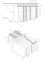
도 2는 종래의 기술에 따른 철도 교량과 토공 접속부의 노반 강화방법이 적용된 철도 교량과 토공 접속부의 노반 상태를 나타내는 단면도 및 사시도이다.FIG. 2 is a cross-sectional view and a perspective view showing a railroad bridge and an earth connection portion to which a railway bridge and a soil connection portion of a conventional art are subjected to a road surface strengthening method.
도 2에 도시된 바와 같이, 종래의 기술에 따른 철도 교량과 토공 접속부의 노반 강화방법은, 드릴장비를 이용하여 철도 교량(21)과 근접된 토공부(23)의 일부 구간에 완충구간을 설정하고, 수개의 구멍(27)을 정해진 간격 및 깊이로 굴삭 천공하는 공정; 드릴장비의 비트 또는 로드를 구멍(27)으로부터 회수하는 공정; 각각의 구멍(27)에 그라우트재를 주입시켜 가압하여 마이크로파일(29)을 형성하는 공정; 마이크로파일(29) 상단부의 토공부(23) 상면에 정해진 두께로 콘크리트층(30)을 타설하는 공정; 및 콘크리트층(30) 상부로 새로운 도상자갈(24)을 채우는 공정으로 이루어지며, 후속적으로, 도상자갈(24) 및 교량(21) 상부에 침목(25) 및 레일(26)을 포함하는 궤도를 형성한다.As shown in FIG. 2, a railway bridge and a tunnel connection strengthening method according to the related art are constructed such that a buffer zone is set in a part of a part of the
구체적으로, 철도 교량(21)과 접속되는 토공부(23)에 도상자갈(24)을 포설하기 전에 강성 변화를 갖는 부위를 완충구간으로 설정하고, 지반 강화를 위한 마이크로파일(29)을 성형하기 위한 기초 작업으로 드릴장비를 이용하여 교대(22)와 근접된 토공부(23)의 일부 구간에 정해진 지름을 갖는 수개의 구멍(27)을 정해진 깊이까지 굴삭 천공하게 된다.Specifically, a site having a change in stiffness is set as a buffer zone before the
이때, 구멍(27)의 간격은 교대(22)에 근접되어 가면 갈수록 가로, 세로 양방향에 대해 그 간격이 점차 좁아지도록 조밀하게 천공함과 동시에 그 깊이도 서서히 더 깊도록 천공함으로써 완충구간에서 자연스럽게 강성 변화가 이루어질 수 있다.At this time, the intervals of the
이러한 드릴 장비를 이용한 다수의 구멍(27)의 천공이 완료되면, 해당 구멍(27)으로부터 드릴장비의 비트 또는 로드를 회수한 다음 각각의 구멍(27)에 시멘트, 모래 벤트나이트, 물유리 등의 약액을 섞어서 만들어진 그라우트재를 곧 바로 주입함과 동시에 가압하거나, 또한, 철근(28)을 삽입 설치한 후 그라우트재를 주입 및 가압하여 각각의 구멍 내에서 해당 구멍의 지름 및 깊이에 대응하는 굵기 및 길이를 갖는 마이크로파일(29)을 성형한다.When drilling of the plurality of
이러한 그라우팅 공법에 의해 성형된 마이크로파일(29) 각각의 지지력은 선단 지지 보다는 구멍(27) 내면과 접촉되는 외주면 마찰력에 의해 발휘되는데, 이러한 마이크로파일(29)이 구멍 내에서 지반과 일체로 거동하므로 지반 개량 효과를 얻을 수 있다.The supporting force of each of the
특히, 구멍(27)을 천공할 때 교대(22)로부터 먼 거리에 위치한 토공부(23)의 일정 부분으로부터 교대에 근접되어 갈수록 그 거리를 좁혀가며 조밀하게 천공함과 동시에 그 깊이를 깊게 형성함으로써 구멍(27)에 그라우트재를 주입 및 가압하여 형성시킨 마이크로파일(29)의 간격 및 길이가 교대에 근접할수록 조밀하면서 깊게 형성된다.Particularly, when drilling the
따라서 교량(21)과 토공부(23)가 접속되는 일정 구간의 토공부(23)에 대한 지반 강성을 교대(22)로 갈수록 점진적이고 자연스럽게 증강시킬 수 있어 교량과 토공 접속부 사이에서 발생되는 소성 및 탄성침하로 인한 침목 들뜸 및 궤도 틀림, 노반 불량으로 인한 배수 불량, 침하 및 승차감 악화 등을 미연에 방지할 수 있다.Therefore, the ground stiffness of the
또한, 구멍(27) 속에 그라우트재만 주입 및 가압하는 방식을 통해 마이크로파일(29)을 성형하는 방식보다는 구멍(27)에 철근(28)들을 삽입 및 설치하고 나머지 공간부에 그라우트재를 충진 및 가압하는 방식을 통해 마이크로파일(29)을 성형하면 그 강도가 더욱 증강될 수 있다. 이러한 철근(28)의 설치 여부는 마이크로파일(29)의 지름과 길이 및 설치 개수를 포함하여 지반 강도의 정도 등에 따른 데이터에 의해 결정된다.It is also possible to insert and install the
또한, 구멍(27) 속에 철근(28) 및 그라우트재를 주입하고 가압하여 마이크로파일(29)을 성형한 후, 그 상면에 곧바로 도상자갈(24)을 포설할 경우 토공부(23)의 지지강성이 마이크로파일(29)이 설치된 주위에 집중되고, 마이크로파일(29) 사이의 공간부는 연약지반의 형태를 그대로 가질 우려가 있다. 이에 따라, 마이크로파일(29) 상단부의 토공부(23) 상면에 정해진 두께로 콘크리트층(30)을 타설하고, 그 상부로 새로운 도상자갈(24)을 채워주는 형태를 채택하여 이를 방지할 수 있다.When the
이때, 콘크리트층(30)은 자갈이 섞인 시멘트를 이용하여 양생하는 것이 좋으며, 그 두께는 지반의 조건에 따라 결정된다. 물론, 마이크로파일(29)의 직경, 길이, 주입재의 종류 및 주입 압력 등의 제원은 파일 설치 및 지반조건에 따른 토공부(23)의 지지강성 증가 효과를 해석적인 방법을 통해 평가하여 교량(21)에서 토공부(23)로의 자연스러운 지지강성 변화가 이루어질 수 있도록 결정될 수 있다.At this time, the
또한, 마이크로파일(29)의 배치는 교량(21)의 교대(22)에서 토공부(23)로 자연스럽게 강성 변화가 이루어질 수 있도록 완충구간에서 교대(2)에 근접할수록 조밀하면서도 깊게 배치하고, 토공부(23)측으로 진행하면서 차츰 그 개수가 감소되면서 얕게 배치될 수 있다. 이때, 말뚝 형태를 갖는 마이크로파일(29)의 배치에 따른 노반 강성의 변화는 3차원 유한 요소 해석 등으로 적용한 수치해석 방법으로 평가될 수 있다.The arrangement of the
종래의 기술에 따른 철도 교량과 토공 접속부의 노반 강화방법에 따르면, 교대 부근의 토공부에 드릴장비를 이용하여 구멍들을 천공하고, 이에 그라우트재를 주입 및 가압하는 방식을 통해 수개의 마이크로파일을 타설하여 지반 강성을 점진적이고 자연스럽게 증강하여 교량과 토공 접속부 사이에서 발생되는 소성 및 탄성침하로 인한 침목 들뜸 및 궤도 틀림, 노반불량으로 인한 배수 불량, 침하 및 승차감 악화 등을 미연에 방지할 수 있다.According to the railway bridge and the method of reinforcing the road surface of the earth connection according to the related art, holes are drilled in a soil drilling machine in the vicinity of the shift, and several micro files are poured through a method of injecting and pressurizing the grout material. The ground rigidity can be gradually and naturally enhanced to prevent the treadmill tilting and track failure caused by the plasticity and elastic settlement occurring between the bridge and the earth connection portion, poor drainage due to road surface roughness, deterioration of sinking and riding comfort.
하지만, 종래의 기술에 따른 철도 교량과 토공 접속부의 노반 강화방법의 경우, 지반 강성이 점진적으로 증가하도록 그라우트재를 주입 및 가압하는 방식을 통해 수개의 마이크로파일을 타설해야 하므로, 시공기간이 증가하게 된다.However, in the case of a conventional method of reinforcing a roadbed bridge and a road connection of an earth connection, several micropiles have to be laid through the method of injecting and pressing the grout material so that the ground stiffness gradually increases. do.
한편, 고속철도 등의 궤도를 부설함에 있어서, 궤도틀림 발생이 큰 문제가 되고, 자갈을 이용한 일반 자갈도상 궤도의 경우, 열차 통행시의 자갈 비산 등의 문제가 크게 대두되고 있기 때문에, 토사 지반에 대해서도 콘크리트 궤도를 이용하는 방안이 고려되고 있는 실정이다. 토사 지반으로 이루어진 노반에 콘크리트 궤도를 사용함에 있어서 가장 중요한 사항 중 하나는 노반의 침하를 사전에 정한 기준값 이내로 유지함으로써, 열차 차량의 주행 안정성 및 궤도의 구조적인 안정성을 확보하고, 이에 필요한 유지보수 노력을 최소화하는 것이다. 이러한 콘크리트 궤도는 종래의 자갈도상 궤도와 달리 침하가 발생하였을 경우, 궤도의 사용성 저하가 큰데 반하여 이에 대처할 수 있는 방안이 매우 제한적이므로, 침하의 계측이 매우 중요하다.On the other hand, in laying tracks such as high-speed railways, the occurrence of a faulty track becomes a serious problem, and in the case of the ordinary gravel road using gravel, problems such as scattering of gravel during the passage of a train are significantly raised. And a method of using a concrete track is being considered. One of the most important points in using concrete tracks for roadbed construction is to keep the roadbed subsidence within a predetermined value and to secure the stability of the trains and the structural stability of the track, . In contrast to the conventional gravel road track, when the settlement occurs, the use of the concrete track is greatly deteriorated, while the countermeasures against such a concrete track are very limited. Therefore, the measurement of the settlement is very important.
전술한 바와 같이, 토공 접속부는 교량과 토공, 터널과 토공, 유도상궤도와 무도상궤도 등 궤도를 지지하는 하부구조물(Sub-structure)의 지지 강성이 변화하는 구간을 말하며, 이러한 지지 강성의 차이에 의하여 시공기면(Formation level)에 단차가 발생하거나 동적 특성의 급변에 의하여 열차 주행시 궤도틀림의 진행, 승차감의 악화 등을 일으키기 쉽다.As described above, the earth connection portion refers to a section in which the support stiffness of a sub-structure supporting a track, such as a bridge, earth, tunnel, earth, Due to the occurrence of a step in the formation level or sudden change of the dynamic characteristic, it is easy to cause the trajectory error and the ride feeling to deteriorate when the train is running.
이러한 문제점을 해결하고자 많은 연구를 하고 있지만, 현재까지 획기적인 해결 방안은 제시되지 못하고 있다. 그 이유는 실제 토공 접속부에서의 문제는 열차의 주행과 지지 강성의 불균형 이외에도 강우, 결빙, 배수 등의 환경적인 원인과 토공 및 교량의 구조적인 원인 등 다양한 원인을 내포하고 있기 때문이다.Although many studies have been conducted to solve these problems, no breakthrough solution has been proposed so far. The reason for this is that the problem at the actual earth connection includes various causes such as environmental causes such as rainfall, freezing and drainage, and structural causes of the earth and bridges in addition to unevenness of train running and supporting rigidity.
또한, 이러한 토공 접속부는 교량, 궤도 및 노반의 상호작용 등으로 인해 매우 복잡하게 거동하며, 이에 따라 설계 단계에서 정확한 거동을 평가하는 것이 매우 어렵고 대부분 경험적으로 평가하고 있다. 따라서 이러한 토공 접속부의 정확한 이해와 성능을 개선하기 위해서는 다양한 접근과 노력이 필요한 실정이며, 이러한 토공 접속부의 보강 방안은 어프로치 블록(Approach Block), 어프로치 슬래브(Approach Slab), 보조 슬래브 및 전단키(Shear Key) 등이 사용될 수 있다.In addition, such earth connection portions behave very complicatedly due to the interaction of bridges, orbits and bedrocks, and it is very difficult and often empirically evaluated to evaluate the correct behavior at the design stage. Therefore, various approaches and efforts are needed to improve the understanding and performance of the earth connection part. The approach of the earth connection part includes an approach block, an approach slab, a support slab, and a shear key ) May be used.
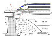
도 3a는 종래의 기술에 따른 어프로치 블록을 구비한 철도 슬래브 궤도 구조물을 나타내는 도면이고, 도 3b는 종래의 기술에 따른 어프로치 블록을 구비한 철도 슬래브 궤도 구조물의 문제점을 설명하기 위한 도면이다.FIG. 3A is a view showing a railway slab track structure having an approach block according to a conventional technique, and FIG. 3B is a view for explaining a problem of a railway slab track structure having an approach block according to a conventional technique.
도 3a를 참조하면, 종래의 기술에 따른 어프로치 블록을 구비한 철도 슬래브 궤도 구조물은, 교대(41), 교량받침(42), 교량(43), 콘크리트 처리 자갈(44), 하부 및 상부 성토(45), 콘크리트 처리 도상(46)을 포함하며, 이때, 콘크리트 처리 자갈(44)이 어프로치 블록 역할을 한다.3A, a railway slab track structure having an approach block according to the related art includes an
도 3a에 도시된 바와 같이, 도로 교량(43)이나 철도 교량 등에서, 교대(41)는 주로 철근 콘크리트로 구성되며, 그 배면에 형성되는 토공부는 토사 등으로 구성되는데, 도 3b에서 도면부호 B로 도시된 바와 같이, 서로 강성이 상이한 재료를 이용하여 시공되므로, 다짐 작업을 수행하더라도 토공부의 침하가 발생하게 되고, 교대(41)와 토공부가 접하는 부분은 쉽게 매몰되는 현상이 발생한다. 이와 같은 현상은 비단 교대(41)뿐만 아니라, 콘크리트 암거의 경우에도 마찬가지인데 콘크리트 암거 측면이나 옹벽의 배면에 채워지는 토공부에서도 전술한 현상이 발생하게 된다.As shown in Fig. 3A, in the case of the
또한, 교대, 터널, 박스 구조물에 인접한 토공 구간은, 도 3b에서 도면부호 C로 도시된 바와 같이, 구조물에 비해 상대적으로 강성이 작기 때문에 동일한 하중이 재하될 경우, 강성이 작은 토공 부분에 더 많은 침하가 발생하게 된다. 이러한 구조물과 토공구간으로 급격한 강성 변화를 방지하기 위하여 중간 부분에 접속부 구조를 두어 강성의 차이를 완만하게 한다. 특히, 고속철도의 경우, 궤도의 평탄성은 속도에 매우 중요한 요소이기 때문에 허용치 이상의 변위가 발생하면 궤도면의 단차로 인한 충격하중으로 인해 차량(50)의 운행 및 안전성에 영향을 미치게 된다.Also, as shown in FIG. 3B, the earth section adjacent to the alternation, tunnel, and box structure is relatively small in rigidity as compared with the structure, so that when the same load is applied, So that settlement occurs. In order to prevent sudden change of stiffness by such a structure and a ground section, a connection structure is provided at the middle portion to reduce the difference in rigidity. Particularly, in the case of high-speed railway, the flatness of the track is a very important factor in speed, so that when a displacement exceeding the allowable value occurs, the impact and safety of the
특히, 교대(41)의 경우, 일반적으로 수직하중을 받는 구조물과 달리 수직하중과 수평하중을 동시에 발생하기 때문에 이에 대한 저항할 수 있도록 구조를 강화시켜야 한다. 그러나 현행 구조물은 어프로치 슬래브, 어프로치 블록, 시멘트 안정처리 등 시공 단계가 복잡하고, 여러 종류의 재료를 사용하게 되어 재료적 특성에 의해 침하가 다르게 거동하는 현상이 발생하고 있으며, 또한, 대부분 수직하중을 고려하고 있다.Particularly, in the case of the shift (41), since the vertical load and the horizontal load are generated at the same time, unlike the structure which is normally subjected to the vertical load, the structure should be strengthened so as to resist the load. However, the current structure is complicated in construction steps such as approach slab, approach block, and cement stabilization treatment, and various types of materials are used, so settlement behaves differently due to material properties, and most of the vertical loads .
그러나 종래의 기술에 따른 어프로치 블록은 콘크리트 등을 배합한 흙을 정해진 형상으로 부설하는 것으로 실제 시공시에 정확한 크기로 부설하는 것이 매우 어렵다는 문제점이 있었다. 또한, 이러한 어프로치 블록의 부설 후에 침하가 발생하는 경우가 다수 발견되고 있고, 예를 들면, 콘크리트 슬래브 궤도의 경우, 균열이 발생하는 경우도 있다. 또한, 종래의 기술에 따른 어프로치 블록을 구비한 철도 슬래브 궤도 구조물은 시공이 복잡하고, 어려우며 기간이 많이 소요된다는 문제점이 있었다.However, the approach block according to the prior art has a problem that it is difficult to lay the concrete containing the concrete in a predetermined shape at the time of actual construction. In addition, there are many cases in which settlement occurs after the installation of such an approach block. For example, in the case of a concrete slab track, cracks may occur. In addition, the railway slab track structure provided with the approach block according to the related art has a problem that the construction is complicated, difficult, and requires a long period of time.
전술한 문제점을 해결하기 위한 선행기술로서, 대한민국 등록특허번호 제10-1507523호에는 "격자형 어프로치 블록을 구비한 철도 슬래브 궤도 구조물 및 그 시공 방법"이라는 명칭의 발명이 개시되어 있는데, 도 4를 참조하여 설명한다.As a prior art for solving the above-mentioned problems, Korean Patent No. 10-1507523 discloses an invention entitled " Railway slab track structure provided with a grid-type approach block and its construction method " .
도 4는 종래의 기술에 따른 격자형 어프로치 블록을 구비한 철도 슬래브 궤도 구조물을 나타내는 도면이다.4 is a view showing a railway slab track structure having a lattice-type approach block according to the prior art.
도 4를 참조하면, 종래의 기술에 따른 격자형 어프로치 블록을 구비한 철도 슬래브 궤도 구조물은, 교량과 철도의 토공 접속부에 형성되는 철도 슬래브 궤도 구조물로서, 원지반(61), 교대(62), 교량받침(63), 교량(64), 콘크리트 처리 자갈(65), 하부 및 상부 성토(66), 콘크리트 상판(67), 철도 슬래브 궤도(68) 및 격자형 어프로치 블록(69)을 포함한다.Referring to FIG. 4, a railway slab track structure having a lattice-type approach block according to a related art is a railway slab track structure formed at a connecting portion of a bridge and a railway. The railway slab track structure includes a
콘크리트 처리 자갈(65)은 교량(64) 및 철도의 토공 접속부에서 선단지지력을 확보하도록 교대(62)의 배면에 시공된다.The concrete treated
하부 및 상부 성토(66) 중에서 하부 성토는 콘크리트 처리 자갈(65)의 측면에서 원지반(61) 상에 적층 형성되며, 상부 성토는 하부 성토 상에 적층 형성된다.In the lower and
콘크리트 상판(67)은 콘크리트 처리 도상으로서, 격자형 어프로치 블록(69) 및 상부 성토 상에 형성된다.The concrete
철도 슬래브 궤도(68)는 열차(70)가 운행할 수 있도록 궤도, 침목 및 레일을 포함하며, 콘크리트 상판(67) 상에 형성된다.The
격자형 어프로치 블록(69)은 상단 및 하단 콘크리트 가로부재 및 상단 및 하단 콘크리트 세로부재가 격자형 프레임(Lattice Frame) 구조로 제작되어 라멘(Rahmen)으로 거동하며, 교량(64) 및 철도의 토공 접속부에서 연직방향의 지지강성을 점차적으로 변화시키도록 길이가 상이한 하단 콘크리트 세로부재가 콘크리트 처리 자갈(65) 상에 연속적으로 매립 배치된다.The lattice-
다시 말하면, 격자형 어프로치 블록(89)은 교량 및 철도의 토공 접속부에 설치되고, 이때, 연직방향의 지지강성을 점차적으로 변화시키기 위하여 길이가 다른 콘크리트 세로부재를 연속적으로 배치하여, 즉, 콘크리트 세로부재의 길이를 점진적으로 짧게 배치함으로써 콘크리트 가로부재와 결합되도록 격자형(lattice)으로 제작된다. 이때, 콘크리트 가로부재의 경우, 프리캐스트 제작되고, 콘크리트 세로부재는 현장타설 방식으로 매립 시공된다. 이에 따라 격자형 어프로치 블록(69)을 프리캐스트 제작함으로써 시공이 간단하고 시공 기간을 단축할 수 있다.In other words, the lattice-
또한, 격자형 어프로치 블록(69)은 철근 콘크리트를 이용한 격자형 프레임 구조로 제작되어 라멘(Rahmen)으로 거동하며, 비교적 가벼운 무게를 가지고, 자중에 의한 침하를 최소화할 수 있고, 이러한 격자형 프레임 구조로 인하여 노반의 선단지지력이 커지게 된다.In addition, the lattice-
종래의 기술에 따른 격자형 어프로치 블록을 구비한 철도 슬래브 궤도 구조물에서, 격자형 어프로치 블록(69)은 기존의 어프로치 블록보다 시공성이 좋고 성능이 우수한 격자형 어프로치 블록에 의해, 콘크리트 슬래브 궤도의 부설 후 침하가 발생하는 것을 방지하고, 균열 발생을 방지할 수 있다.In the railway slab track structure provided with the lattice-type approach block according to the related art, the lattice-
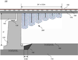
한편, 도 5는 종래의 기술에 따른 철도 교량과 토공 접속부의 노반보강 방법에 의해 보강된 궤도 구조물을 나타내는 도면이다.5 is a view showing a track structure reinforced by a railway bridge and a road surface reinforcement method of the earth connection portion according to a conventional technique.
도 5를 참조하면, 종래의 기술에 따른 철도 교량과 토공 접속부의 노반보강 방법에 의해 보강된 궤도 구조물은, 원지반(81), 교대(82), 교량받침(83), 교량(84), 바닥콘크리트(85), 성토층(86), 보강재(87), 뒷채움재(88), 콘크리트 상판(89) 및 철도 슬래브 궤도(90)를 포함한다.5, a track structure reinforced by a railway bridge and a road surface reinforcement method of the earth connection portion according to the related art includes a
종래의 기술에 따른 철도 교량과 토공 접속부의 노반보강 방법의 경우, 뒷채움 부분을 굴착하고 재다짐하여 성토층을 형성한다. 즉, 교대(82)의 배면에 수직 방향으로 보강재(87)를 설치하고, 뒷채움재(87)를 충진하며, 이후 뒷채움 부분을 굴착한 후 재다짐하여 성토층을 형성하며, 이후, 콘크리트 상판(89) 및 철도 슬래브 궤도(90)를 시공함으로써 궤도 구조물을 형성한다.In the case of the conventional railway bridge and roadbed reinforcement method of the earth connection portion, the backfill is excavated and re-compacted to form a clayey layer. That is, the
하지만, 종래의 기술에 따른 철도 교량과 토공 접속부의 노반보강 방법의 경우, 열차하중의 전달범위를 고려하지 않고 전체 뒷채움 깊이까지 뒷채움재를 성토하여 보강하기 때문에 시공기간이 길어지고 시공비용이 증가할 수 있다는 문제점이 있다.However, in the case of the conventional railway bridge and roadbed reinforcement method of the earth connection, since the backfill material is filled up to the entire backfill depth without considering the transmission range of the train load, the construction period is lengthened and the construction cost is increased .
전술한 문제점을 해결하기 위한 본 발명이 이루고자 하는 기술적 과제는, 교량과 철도의 토공 접속부의 노반보강시, 침투 그라우팅 방식으로 상부노반 보강층을 형성함으로써 상부노반 강성을 증대시킬 수 있고, 전체 뒷채움 깊이가 아닌 상부노반 이하의 열차하중의 전달범위까지만 상부노반을 보강할 수 있는, 열차하중의 전달범위를 고려한 토공 접속부의 노반보강 방법을 제공하기 위한 것이다.SUMMARY OF THE INVENTION It is an object of the present invention to solve the above-mentioned problems and provide a method of manufacturing a bridge structure, which is capable of increasing an upper roadbed rigidity by forming an upper roadbed reinforcement layer by a penetration grouting method, The present invention is to provide a road surface reinforcement method of an earth connection unit considering the transmission range of a train load, which can reinforce the upper roadbed only to the range of the train load below the upper roadbed.
본 발명이 이루고자 하는 다른 기술적 과제는, 교량과 철도의 토공 접속부의 노반보강시, 상부노반 보강층의 보강 깊이의 점진적 감소를 통해 궤도강성 천이구간을 용이하게 형성할 수 있는, 열차하중의 전달범위를 고려한 토공 접속부의 노반보강 방법을 제공하기 위한 것이다.It is another object of the present invention to provide a railway load transfer system capable of easily forming an orbital stiffness transition section by progressively reducing the depth of reinforcement of an upper roadbed reinforcement layer during roadbed reinforcement of bridge- And to provide a method of reinforcing the road surface of the earth connection portion.
전술한 기술적 과제를 달성하기 위한 수단으로서, 본 발명에 따른 열차하중의 전달범위를 고려한 토공 접속부의 노반보강 방법은, 교량과 철도의 토공 접속부의 노반보강 방법에 있어서, a) 토공 접속부의 노반 보강을 위해 교대의 배면의 원지반 상부에 뒷채움재로 성토층을 형성하는 단계; b) 토공 접속부를 통과하는 열차의 수직 방향으로 열차하중 전달범위를 결정하는 단계; c) 상기 열차하중의 전달범위를 고려하여 상기 교대의 배면에 접하는 상부 성토층에 침투 그라우팅을 실시하여 상부노반 보강층을 형성하는 단계; d) 궤도강성 천이구간까지 상기 상부노반 보강층의 보강 깊이를 점진적으로 감소시키면서 순차적으로 침투 그라우팅을 실시하는 단계; 및 e) 상기 상부노반 보강층 또는 상부 성토층 상에 궤도 상부 구조물을 시공하는 단계를 포함하되, 상기 상부노반 보강층은 상부노반 하부의 열차하중의 전달범위까지만 보강하는 것을 특징으로 한다.As a means for achieving the above-mentioned technical object, a road surface reinforcement method for a ground connection part considering a range of a train load transfer according to the present invention is a road surface reinforcement method for a ground connection part of a bridge and a railway, comprising: a) Forming an embankment layer with a backfill material on the backside of the backside of the alternation; b) determining a train load transmission range in the vertical direction of the train passing through the earth connection portion; c) performing an infiltration grouting in the upper clay layer adjacent to the alternate back surface in consideration of the transmission range of the train load to form an upper carburizing layer; d) sequentially performing infiltration grouting while gradually reducing the reinforcing depth of the upper road-marking reinforcement layer to the orbit stiffness transition section; And e) constructing an upper track structure on the upper carburized reinforcing layer or the upper filler layer, wherein the upper carburization reinforcing layer is reinforced only up to the transmission range of the train load in the lower part of the upper part.
여기서, 상기 c) 단계에서 열차하중의 전달범위를 고려하여 상기 성토층을 천공하고, 상기 열차하중의 전달범위까지만 천공 부위에 그라우트재를 주입 및 가압하여 상기 상부노반 보강층을 형성할 수 있다.In the step c), the embankment layer may be drilled in consideration of the range of the train load transfer, and the grooved material may be injected into and pressurized only to the region where the train load is transferred, thereby forming the upper roadbed reinforcement layer.
여기서, 상기 d) 단계의 궤도강성 천이구간은 상기 교대 높이의 2배까지 5m 이상 형성되는 것이 바람직하다.Here, it is preferable that the orbital stiffness transition period of the step d) is formed by 5 m or more up to twice the alternating height.
여기서, 상기 a) 단계를 수행하기 전에 교대의 배면 하부에 바닥콘크리트를 타설하되, 상기 교대와 원지반 사이에 적어도 0.8m 이상의 바닥콘크리트를 타설할 수 있다.Here, before performing the step a), the bottom concrete may be laid under the alternate backside, and at least 0.8 m of the bottom concrete may be laid between the alternation and the ground.
여기서, 상기 e) 단계의 궤도 상부 구조물은, 노출된 상부 전면에 콘크리트를 타설하여 형성되는 상부노반; 상기 상부노반 상에 소정 간격으로 배치되는 침목; 및 상기 침목 상에 설치되는 레일을 포함할 수 있다.Here, the orbital upper structure of the step e) may include: an upper runway formed by pouring concrete on the exposed upper surface; A sleeper disposed at a predetermined interval on the upper bed; And a rail installed on the treadmill.
본 발명에 따르면, 교량과 철도의 토공 접속부의 노반보강시, 침투 그라우팅 방식으로 상부노반 보강층을 형성함으로써 상부노반 강성을 증대시킬 수 있고, 전체 뒷채움 깊이가 아닌 상부노반 이하의 열차하중의 전달범위까지만 상부노반을 보강할 수 있다. 이에 따라 시공기간 및 시공비용을 감축시킬 수 있다.According to the present invention, it is possible to increase the upper roadbed rigidity by forming the upper roadbed reinforcement layer by the infiltration grouting method when the road connecting portion of the bridge and the railway is reinforced. In addition, The upper bed plate can be reinforced. As a result, construction time and construction costs can be reduced.
본 발명에 따르면, 교량과 철도의 토공 접속부의 노반보강시, 상부노반 보강층의 보강 깊이의 점진적 감소를 통해 궤도강성 천이구간을 용이하게 형성할 수 있다.According to the present invention, the orbital stiffness transition section can be easily formed through gradual reduction of the reinforcing depth of the upper road-curved reinforcing layer at the time of reinforcing the road-to-ground connection portion of the bridge and the railway.
도 1은 종래의 기술에 따른 철도 교량과 토공 접속부의 노반 상태를 나타내는 도면이다.
도 2는 종래의 기술에 따른 철도 교량과 토공 접속부의 노반 강화방법이 적용된 철도 교량과 토공 접속부의 노반 상태를 나타내는 단면도 및 사시도이다.
도 3a는 종래의 기술에 따른 어프로치 블록을 구비한 철도 슬래브 궤도 구조물을 나타내는 도면이고, 도 3b는 종래의 기술에 따른 어프로치 블록을 구비한 철도 슬래브 궤도 구조물의 문제점을 설명하기 위한 도면이다.
도 4는 종래의 기술에 따른 철도 교량과 토공 접속부의 노반보강 방법에 의해 보강된 궤도 구조물을 나타내는 도면이다.
도 5는 종래의 기술에 따른 격자형 어프로치 블록을 구비한 철도 슬래브 궤도 구조물을 나타내는 도면이다.
도 6은 본 발명의 실시예에 따른 열차하중의 전달범위를 고려한 토공 접속부의 노반보강 궤도 구조물을 나타내는 단면도이다.
도 7은 본 발명의 실시예에 따른 열차하중의 전달범위를 고려한 토공 접속부의 노반보강 방법의 동작흐름도이다.
도 8a 내지 도 8f는 각각 본 발명의 실시예에 따른 열차하중의 전달범위를 고려한 토공 접속부의 노반보강 방법을 구체적으로 설명하기 위한 도면들이다.BRIEF DESCRIPTION OF DRAWINGS FIG. 1 is a view showing a roadbed of a railway bridge and an earth connection portion according to a conventional technique.
FIG. 2 is a cross-sectional view and a perspective view showing a railroad bridge and an earth connection portion to which a railroad bridge and an earth connection portion of the earth connection portion according to the related art are applied.
FIG. 3A is a view showing a railway slab track structure having an approach block according to a conventional technique, and FIG. 3B is a view for explaining a problem of a railway slab track structure having an approach block according to the related art.
4 is a view showing a track structure reinforced by a railway bridge and a road surface reinforcement method of a ground connection according to a conventional technique.
5 is a view showing a railway slab track structure having a lattice-type approach block according to a conventional technique.
6 is a cross-sectional view showing a road surface reinforced track structure of the earth connection portion taking into account the transmission range of the train load according to the embodiment of the present invention.
FIG. 7 is a flowchart illustrating a method of reinforcing a road surface joint of a ground joint according to an embodiment of the present invention, taking into consideration the range of transmission of a train load.
FIGS. 8A to 8F are views for explaining a method of reinforcing a road surface joint portion of a soil contact joint considering the range of train load transfer according to an embodiment of the present invention.
아래에서는 첨부한 도면을 참조하여 본 발명이 속하는 기술분야에서 통상의 지식을 가진 자가 용이하게 실시할 수 있도록 본 발명의 실시예를 상세히 설명한다. 그러나 본 발명은 여러 가지 상이한 형태로 구현될 수 있으며 여기에서 설명하는 실시예에 한정되지 않는다. 그리고 도면에서 본 발명을 명확하게 설명하기 위해서 설명과 관계없는 부분은 생략하였으며, 명세서 전체를 통하여 유사한 부분에 대해서는 유사한 도면 부호를 붙였다.Hereinafter, embodiments of the present invention will be described in detail with reference to the accompanying drawings, which will be readily apparent to those skilled in the art. The present invention may, however, be embodied in many different forms and should not be construed as limited to the embodiments set forth herein. In order to clearly illustrate the present invention, parts not related to the description are omitted, and similar parts are denoted by like reference characters throughout the specification.
명세서 전체에서, 어떤 부분이 어떤 구성요소를 "포함"한다고 할 때, 이는 특별히 반대되는 기재가 없는 한 다른 구성요소를 제외하는 것이 아니라 다른 구성요소를 더 포함할 수 있는 것을 의미한다.Throughout the specification, when an element is referred to as "comprising ", it means that it can include other elements as well, without excluding other elements unless specifically stated otherwise.
[열차하중의 전달범위를 고려한 토공 접속부의 노반보강 궤도 구조물(100)][Roadbed Reinforced Track Structure of Ground Connection Considering Transmission Range of Train Load (100)]
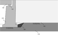
도 6은 본 발명의 실시예에 따른 열차하중의 전달범위를 고려한 토공 접속부의 노반보강 궤도 구조물을 나타내는 단면도이다.6 is a cross-sectional view showing a road surface reinforced track structure of the earth connection portion taking into account the transmission range of the train load according to the embodiment of the present invention.
도 6을 참조하면, 본 발명의 실시예에 따른 열차하중의 전달범위를 고려한 토공 접속부의 노반보강 궤도 구조물(100)은, 바닥콘크리트(150), 성토층(160), 상부노반(170), 침목(180), 레일(190) 및 상부노반 보강층(200)을 포함한다.Referring to FIG. 6, a roadbed reinforcing
바닥콘크리트(150)는, 원지반(110) 상에 교대(120)가 시공되고, 교량받침(130) 상에 교량(140)이 시공된 상태에서, 토공 접속부의 노반 보강을 위해 교대(120)의 배면 하부에 타설된다. 이때, 상기 바닥콘크리트(150)는 상기 교대(120) 배면 하부에서 상기 교대(120)와 원지반(110) 사이에 적어도 0.8m 이상 타설되는 것이 바람직하다.The
성토층(160)은 뒷채움재로서 상기 교대(120) 배면의 원지반(110) 상부에 성토되어 다짐을 수행하여 형성된다.The
상부노반 보강층(200)은 토공 접속부를 통과하는 열차의 수직 방향으로 열차하중 전달범위를 결정한 후, 상기 열차하중의 전달범위를 고려하여 상기 교대(120)의 배면에 접하는 상부 성토층(160)에 침투 그라우팅을 실시하여 형성된다. 이때, 상기 상부노반 보강층(200)은 보강 깊이를 점진적으로 감소시키면서 궤도강성 천이구간까지 순차적으로 침투 그라우팅을 실시하여 형성된다. 여기서, 상기 궤도강성 천이구간은 상기 교대(120) 높이(H)의 2배까지 5m 이상 형성되는 것이 바람직하다. 예를 들면, 상기 상부노반 보강층(200)은 상기 열차하중의 전달범위를 고려하여 상기 성토층(160)을 천공하고, 상기 열차하중의 전달범위까지만 천공 부위에 그라우트재를 주입 및 가압하여 형성할 수 있지만, 이에 국한되는 것은 아니다.The
상부노반(170)은 상기 상부노반 보강층(200) 또는 상부 성토층(160)의 노출된 상부 전면에 콘크리트를 타설하여 궤도 형성되고, 침목(180)은 상기 상부노반(170) 상에 소정 간격으로 배치되고, 레일(190)은 상기 침목(180) 상에 설치된다. 여기서, 궤도 상부 구조물은 상기 상부노반(170), 침목(180) 및 레일(190)을 포함하지만, 이에 국한되는 것은 아니다.The
본 발명의 실시예에 따른 열차하중의 전달범위를 고려한 토공 접속부의 노반보강 궤도 구조물에 따르면, 침투 그라우팅 방식으로 상부노반 보강층(200)을 형성함으로써 상부노반 강성을 증대시킬 수 있고, 전체 뒷채움 깊이가 아닌 상부노반 이하의 열차하중의 전달범위까지만 상부노반을 보강할 수 있다. 또한, 상부노반 보강층의 보강 깊이의 점진적 감소를 통해 궤도강성 천이구간을 용이하게 형성할 수 있다.According to the roadbed connecting track structure of the earth connection portion taking into consideration the transmission range of the train load according to the embodiment of the present invention, the upper
[열차하중의 전달범위를 고려한 토공 접속부의 노반보강 방법][Roadbed Reinforcement Method of Earth Connection Considering the Range of Train Load Transfer]
도 7은 본 발명의 실시예에 따른 열차하중의 전달범위를 고려한 토공 접속부의 노반보강 방법의 동작흐름도이고, 도 8a 내지 도 8f는 각각 본 발명의 실시예에 따른 열차하중의 전달범위를 고려한 토공 접속부의 노반보강 방법을 구체적으로 설명하기 위한 도면들이다.FIG. 7 is a flow chart illustrating a method of reinforcing a road surface connection of a ground connection according to an embodiment of the present invention. FIGS. 8A to 8F are cross- And drawings for specifically explaining a method of reinforcing a road surface of a connecting portion.
도 7을 참조하면, 본 발명의 실시예에 따른 열차하중의 전달범위를 고려한 토공 접속부의 노반보강 방법은, 교량과 철도의 토공 접속부의 노반보강 방법으로서, 먼저, 토공 접속부의 노반 보강을 위해 교대(120)의 배면 하부에 바닥콘크리트(150)를 타설한다(S110). 구체적으로, 도 8a에 도시된 바와 같이, 교대(120) 배면 하부에서 상기 교대(120)와 원지반(110) 사이에 적어도 0.8m 이상의 바닥콘크리트(150)를 타설한다.Referring to FIG. 7, a road surface reinforcement method for a ground connection portion considering a transmission range of a train load according to an embodiment of the present invention is a road surface reinforcement method for a ground connection portion of a bridge and a railway. First, The
다음으로, 상기 교대(120) 배면의 원지반(110) 상부에 뒷채움재로 성토층(160)을 형성한다(S120). 구체적으로, 도 8b에 도시된 바와 같이, 상기 교대(120)의 배면의 뒷채움을 위해 성토층(160)을 성토 및 다짐을 수행한다.Next, the
다음으로, 토공 접속부를 통과하는 열차(300)의 수직 방향으로 열차하중 전달범위를 결정한다(S130). 즉, 토공 접속부를 통과하는 열차(300)의 열차하중이 수직 방향으로 재하되는 전달범위를 상기 교대(120) 배면으로부터 소정거리, 예를 들면, 궤도강성 천이구간까지 결정한다.Next, the train load transmission range is determined in the vertical direction of the
다음으로, 상기 열차하중의 전달범위를 고려하여 상기 교대(120)의 배면에 접하는 상부 성토층160)에 침투 그라우팅을 실시하여 상부노반 보강층(200)을 형성한다(S140). 구체적으로, 도 8c에 도시된 바와 같이, 상기 결정된 열차하중의 전달범위를 고려하여 상기 교대(120)의 배면에 접하는 상부 성토층160)에 침투 그라우팅을 실시하여 제1 상부노반 보강층(210)을 형성한다. 이때, 상기 열차하중의 전달범위를 고려하여 상기 성토층(160)을 천공하고, 상기 열차하중의 전달범위까지만 천공 부위에 그라우트재를 주입 및 가압하여 상기 상부노반 보강층(200)을 형성할 수 있다.Subsequently, infiltration grouting is performed on the
다음으로, 상기 상부노반 보강층의 보강 깊이를 점진적으로 감소시키면서 궤도강성 천이구간까지 순차적으로 침투 그라우팅을 실시하여 상부노반 보강층(200)을 형성한다(S150). 이때, 상기 상부노반 보강층(200)은 상부노반 하부의 열차하중의 전달범위까지만 보강하게 된다. 구체적으로, 도 8d에 도시된 바와 같이, 상기 상부노반 보강층(200)의 보강 깊이를 점진적으로 감소시키면서 궤도강성 천이구간까지 순차적으로 침투 그라우팅을 실시하여 제2 상부노반 보강층(220) 내지 제N 상부노반 보강층(260)을 형성한다. 여기서, 상기 궤도강성 천이구간은 상기 교대(120) 높이(H)의 2배까지 5m 이상 형성되는 것이 바람직하다.Next, infiltration grouting is sequentially performed to the orbital stiffness transition period while gradually reducing the reinforcing depth of the upper road-marking reinforcement layer to form the upper road-carving reinforcement layer 200 (S150). At this time, the upper
다음으로, 상기 상부노반 보강층(200, 210~260) 또는 상부 성토층(160) 상에 상부노반(170)을 형성한다(S160). 구체적으로, 도 8e에 도시된 바와 같이, 상기 상부노반 보강층(200) 또는 상부 성토층(160)의 노출된 상부 전면에 콘크리트를 타설하여 궤도 상부 구조물 중에서 상부노반(170)을 형성한다.Next, the
후속적으로, 열차(300)가 주행할 수 있도록 상기 상부노반(170) 상에 침목(180) 및 레일(190)을 형성한다. 여기서, 상기 궤도 상부 구조물은, 도 8f에 도시된 바와 같이, 노출된 상부 전면에 콘크리트를 타설하여 형성되는 상부노반(170); 상기 상부노반(170) 상에 소정 간격으로 배치되는 침목(180); 및 상기 침목(180) 상에 설치되는 레일(190)을 포함하지만, 이에 국한되는 것은 아니다.Subsequently, a
결국, 본 발명의 실시예에 따르면, 교량과 철도의 토공 접속부의 노반보강시, 침투 그라우팅 방식으로 상부노반 보강층을 형성함으로써 상부노반 강성을 증대시킬 수 있고, 전체 뒷채움 깊이가 아닌 상부노반 이하의 열차하중의 전달범위까지만 상부노반을 보강함으로써 시공기간 및 시공비용을 감축시킬 수 있고, 또한, 상부노반 보강층의 보강 깊이의 점진적 감소를 통해 궤도강성 천이구간을 용이하게 형성할 수 있다.As a result, according to the embodiment of the present invention, the upper roadbed reinforcement layer can be formed by the penetration grouting method when the road connecting portion of the bridge and the railway is reinforced, and the upper roadbed rigidity can be increased. The construction period and the construction cost can be reduced by reinforcing the upper roadbed only up to the range of the load transmission and the orbital stiffness transition section can be easily formed by progressively reducing the reinforcing depth of the upper roadbed reinforcement layer.
전술한 본 발명의 설명은 예시를 위한 것이며, 본 발명이 속하는 기술분야의 통상의 지식을 가진 자는 본 발명의 기술적 사상이나 필수적인 특징을 변경하지 않고서 다른 구체적인 형태로 쉽게 변형이 가능하다는 것을 이해할 수 있을 것이다. 그러므로 이상에서 기술한 실시예들은 모든 면에서 예시적인 것이며 한정적이 아닌 것으로 이해해야만 한다. 예를 들어, 단일형으로 설명되어 있는 각 구성 요소는 분산되어 실시될 수도 있으며, 마찬가지로 분산된 것으로 설명되어 있는 구성 요소들도 결합된 형태로 실시될 수 있다.It will be understood by those skilled in the art that the foregoing description of the present invention is for illustrative purposes only and that those of ordinary skill in the art can readily understand that various changes and modifications may be made without departing from the spirit or essential characteristics of the present invention. will be. It is therefore to be understood that the above-described embodiments are illustrative in all aspects and not restrictive. For example, each component described as a single entity may be distributed and implemented, and components described as being distributed may also be implemented in a combined form.
본 발명의 범위는 상기 상세한 설명보다는 후술하는 특허청구범위에 의하여 나타내어지며, 특허청구범위의 의미 및 범위 그리고 그 균등 개념으로부터 도출되는 모든 변경 또는 변형된 형태가 본 발명의 범위에 포함되는 것으로 해석되어야 한다.The scope of the present invention is defined by the appended claims rather than the detailed description and all changes or modifications derived from the meaning and scope of the claims and their equivalents are to be construed as being included within the scope of the present invention do.
100: 토공 접속부의 노반보강 궤도 구조물
110: 원지반
120: 교대
130: 교량
140: 교량받침
150: 바닥콘크리트
160: 성토층
170: 상부노반
180: 침목
190: 레일
200, 210~260: 상부노반 보강층
300: 열차100: Roadbed reinforcement track structure of the earth connection portion
110: Paperboard
120: Shift
130: Bridge
140: Bridge support
150: Floor concrete
160: buried layer
170:
180: sleepers
190: Rail
200, 210 to 260: Upper roadbed reinforcement layer
300: Train
Claims (6)
a) 토공 접속부의 노반 보강을 위해 교대(120)의 배면의 원지반(110) 상부에 뒷채움재로 성토층(160)을 형성하는 단계;
b) 토공 접속부를 통과하는 열차(300)의 수직 방향으로 열차하중 전달범위를 결정하는 단계;
c) 상기 열차하중의 전달범위를 고려하여 상기 교대(120)의 배면에 접하는 상부 성토층(160)에 침투 그라우팅을 실시하여 상부노반 보강층(200)을 형성하는 단계;
d) 궤도강성 천이구간까지 상기 상부노반 보강층의 보강 깊이를 점진적으로 감소시키면서 순차적으로 침투 그라우팅을 실시하는 단계; 및
e) 상기 상부노반 보강층(200) 또는 상부 성토층(160) 상에 궤도 상부 구조물을 시공하는 단계
를 포함하되,
상기 상부노반 보강층(200)은 상부노반 하부의 열차하중의 전달범위까지만 보강하는 것을 특징으로 하는 열차하중의 전달범위를 고려한 토공 접속부의 노반보강 방법.In a roadbed reinforcement method for a bridge connecting portion of a bridge and a railway,
a) forming an embankment layer (160) with a backing material on the backing sheet (110) on the back surface of the alternation (120) for reinforcement of the road surface connection portion;
b) determining a train load transmission range in the vertical direction of the train (300) passing through the earth connection portion;
c) forming an upper rough boarding layer 200 by performing penetration grouting on the upper clayey layer 160 contacting the backside of the alternation 120, taking into consideration the transmission range of the train load;
d) sequentially performing infiltration grouting while gradually reducing the reinforcing depth of the upper road-marking reinforcement layer to the orbit stiffness transition section; And
e) constructing an orbital superstructure on the upper bedding strengthening layer 200 or the upper embankment layer 160
, ≪ / RTI &
Wherein the upper board strengthening layer (200) is reinforced only up to a range of transmission of a train load at the lower part of the upper part of the roadbed, taking into account the transmission range of the train load.
상기 c) 단계에서 열차하중의 전달범위를 고려하여 상기 성토층(160)을 천공하고, 상기 열차하중의 전달범위까지만 천공 부위에 그라우트재를 주입 및 가압하여 상기 상부노반 보강층(200)을 형성하는 것을 특징으로 하는 열차하중의 전달범위를 고려한 토공 접속부의 노반보강 방법.The method according to claim 1,
In the step c), the embankment layer 160 is drilled in consideration of the range of the train load transfer, and the grooved material is injected and pressurized only in the region where the train load is transmitted until the upper carpet strengthening layer 200 is formed Wherein the method comprises the steps of:
상기 d) 단계의 궤도강성 천이구간은 상기 교대(120) 높이(H)의 2배까지 5m 이상 형성되는 것을 특징으로 하는 열차하중의 전달범위를 고려한 토공 접속부의 노반보강 방법.The method according to claim 1,
Wherein the orbital stiffness transition period of the step d) is formed to be 5 m or more up to twice the height H of the alternation 120, considering the transmission range of the train load.
상기 a) 단계를 수행하기 전에 교대(120)의 배면 하부에 바닥콘크리트(150)를 타설하되, 상기 교대(120)와 원지반(110) 사이에 적어도 0.8m 이상의 바닥콘크리트(150)를 타설하는 것을 특징으로 하는 열차하중의 전달범위를 고려한 토공 접속부의 노반보강 방법.The method according to claim 1,
It is preferable to place the floor concrete 150 at the bottom of the backside of the alternation 120 before the step a) and to place at least 0.8 m of the bottom concrete 150 between the alternation 120 and the ground pattern 110 A method of reinforcing a roadbed joint of a toe joint considering the range of delivery of a train load.
노출된 상부 전면에 콘크리트를 타설하여 형성되는 상부노반(170);
상기 상부노반(170) 상에 소정 간격으로 배치되는 침목(180); 및
상기 침목(180) 상에 설치되는 레일(190)
을 포함하는 열차하중의 전달범위를 고려한 토공 접속부의 노반보강 방법.The method according to claim 1, wherein the orbital superstructure of step e)
An upper bed panel 170 formed by pouring concrete on the exposed upper surface;
A sleeper 180 disposed at a predetermined interval on the upper bed 170; And
A rail 190 mounted on the sleepers 180,
Wherein the method comprises the steps of:
Priority Applications (1)
| Application Number | Priority Date | Filing Date | Title |
|---|---|---|---|
| KR1020170025368A KR20180098794A (en) | 2017-02-27 | 2017-02-27 | Method for reinforcing rail roadbed of earthwork transitional zone considering transfer range of train load |
Applications Claiming Priority (1)
| Application Number | Priority Date | Filing Date | Title |
|---|---|---|---|
| KR1020170025368A KR20180098794A (en) | 2017-02-27 | 2017-02-27 | Method for reinforcing rail roadbed of earthwork transitional zone considering transfer range of train load |
Publications (1)
| Publication Number | Publication Date |
|---|---|
| KR20180098794A true KR20180098794A (en) | 2018-09-05 |
Family
ID=63594855
Family Applications (1)
| Application Number | Title | Priority Date | Filing Date |
|---|---|---|---|
| KR1020170025368A Ceased KR20180098794A (en) | 2017-02-27 | 2017-02-27 | Method for reinforcing rail roadbed of earthwork transitional zone considering transfer range of train load |
Country Status (1)
| Country | Link |
|---|---|
| KR (1) | KR20180098794A (en) |
Cited By (12)
| Publication number | Priority date | Publication date | Assignee | Title |
|---|---|---|---|---|
| CN109112904A (en) * | 2018-10-22 | 2019-01-01 | 华东交通大学 | Whether one kind is needed reinforcement evaluation method based on apparent measurement road-bridge transition section roadbed |
| CN110158481A (en) * | 2019-06-20 | 2019-08-23 | 中国五冶集团有限公司 | A kind of method and structure of back filling behind abutment construction |
| CN110725162A (en) * | 2019-10-22 | 2020-01-24 | 中铁十局集团第八工程有限公司 | Subgrade device and manufacturing method for rail transit |
| CN111859519A (en) * | 2020-08-03 | 2020-10-30 | 重庆交通建设(集团)有限责任公司 | Three-dimensional calculation analysis method for influence of buttress on interval tunnel and station structure |
| CN112030615A (en) * | 2020-09-21 | 2020-12-04 | 中铁四院集团工程建设有限责任公司 | Directional grouting structure and deviation rectifying system of pier roadbed |
| KR102191009B1 (en) * | 2019-10-08 | 2020-12-14 | 산동 유니버시티 | Acting leakage prevention control method and underground leakage prevention system of subway station sturucture leakage disease |
| CN112411267A (en) * | 2020-11-06 | 2021-02-26 | 中铁第四勘察设计院集团有限公司 | Railway short-circuit foundation |
| CN113215865A (en) * | 2021-06-02 | 2021-08-06 | 中国铁路设计集团有限公司 | Transition section structure of fluidized solidified soil and construction method thereof |
| CN114575209A (en) * | 2022-03-31 | 2022-06-03 | 浙江数智交院科技股份有限公司 | Road rigid pile and preloading soft foundation treatment transition structure and construction method |
| CN115852810A (en) * | 2022-11-10 | 2023-03-28 | 中铁二院工程集团有限责任公司 | A ballastless track road-bridge transition structure and its design method and construction method |
| CN117646355A (en) * | 2024-01-03 | 2024-03-05 | 中国科学院西北生态环境资源研究院 | Frost-proof high-speed railway base structure of frozen soil area in season |
| CN120449283A (en) * | 2025-07-07 | 2025-08-08 | 太原理工大学 | A multi-stage treatment method utilizing underground space of abandoned mines |
Citations (7)
| Publication number | Priority date | Publication date | Assignee | Title |
|---|---|---|---|---|
| KR100620057B1 (en) | 2004-12-24 | 2006-09-08 | 한국철도기술연구원 | Reinforcement method of support stiffness of railway bridge and earthwork |
| KR100683589B1 (en) | 2004-12-24 | 2007-02-15 | 한국철도기술연구원 | Roadbed reinforcement method of railway bridge and earthwork connection |
| KR100768777B1 (en) | 2006-09-22 | 2007-10-19 | 임규동 | Ground reinforcement method of concrete road rail |
| KR101006900B1 (en) | 2008-06-16 | 2011-01-14 | 한국철도기술연구원 | Construction method of backfill reinforcement structure of rigid structure |
| KR101469881B1 (en) | 2012-08-10 | 2014-12-08 | 한국철도기술연구원 | Structure for reinforcing bridge transitional zone and restraining vertical-horizontal deformation, and constructing method for the same |
| KR101507523B1 (en) | 2013-05-07 | 2015-04-06 | 한국철도기술연구원 | Slab track structure for railway with lattice approach block, and construction method for the same |
| KR101543593B1 (en) | 2013-05-21 | 2015-08-11 | 한국철도기술연구원 | Method for reinforcing roadbed of railway, and structure for constructing using the same |
-
2017
- 2017-02-27 KR KR1020170025368A patent/KR20180098794A/en not_active Ceased
Patent Citations (7)
| Publication number | Priority date | Publication date | Assignee | Title |
|---|---|---|---|---|
| KR100620057B1 (en) | 2004-12-24 | 2006-09-08 | 한국철도기술연구원 | Reinforcement method of support stiffness of railway bridge and earthwork |
| KR100683589B1 (en) | 2004-12-24 | 2007-02-15 | 한국철도기술연구원 | Roadbed reinforcement method of railway bridge and earthwork connection |
| KR100768777B1 (en) | 2006-09-22 | 2007-10-19 | 임규동 | Ground reinforcement method of concrete road rail |
| KR101006900B1 (en) | 2008-06-16 | 2011-01-14 | 한국철도기술연구원 | Construction method of backfill reinforcement structure of rigid structure |
| KR101469881B1 (en) | 2012-08-10 | 2014-12-08 | 한국철도기술연구원 | Structure for reinforcing bridge transitional zone and restraining vertical-horizontal deformation, and constructing method for the same |
| KR101507523B1 (en) | 2013-05-07 | 2015-04-06 | 한국철도기술연구원 | Slab track structure for railway with lattice approach block, and construction method for the same |
| KR101543593B1 (en) | 2013-05-21 | 2015-08-11 | 한국철도기술연구원 | Method for reinforcing roadbed of railway, and structure for constructing using the same |
Cited By (14)
| Publication number | Priority date | Publication date | Assignee | Title |
|---|---|---|---|---|
| CN109112904B (en) * | 2018-10-22 | 2020-06-23 | 华东交通大学 | Evaluation method for judging whether roadbed of road bridge transition section needs to be reinforced based on apparent measurement |
| CN109112904A (en) * | 2018-10-22 | 2019-01-01 | 华东交通大学 | Whether one kind is needed reinforcement evaluation method based on apparent measurement road-bridge transition section roadbed |
| CN110158481A (en) * | 2019-06-20 | 2019-08-23 | 中国五冶集团有限公司 | A kind of method and structure of back filling behind abutment construction |
| KR102191009B1 (en) * | 2019-10-08 | 2020-12-14 | 산동 유니버시티 | Acting leakage prevention control method and underground leakage prevention system of subway station sturucture leakage disease |
| CN110725162A (en) * | 2019-10-22 | 2020-01-24 | 中铁十局集团第八工程有限公司 | Subgrade device and manufacturing method for rail transit |
| CN111859519A (en) * | 2020-08-03 | 2020-10-30 | 重庆交通建设(集团)有限责任公司 | Three-dimensional calculation analysis method for influence of buttress on interval tunnel and station structure |
| CN112030615A (en) * | 2020-09-21 | 2020-12-04 | 中铁四院集团工程建设有限责任公司 | Directional grouting structure and deviation rectifying system of pier roadbed |
| CN112411267A (en) * | 2020-11-06 | 2021-02-26 | 中铁第四勘察设计院集团有限公司 | Railway short-circuit foundation |
| CN113215865A (en) * | 2021-06-02 | 2021-08-06 | 中国铁路设计集团有限公司 | Transition section structure of fluidized solidified soil and construction method thereof |
| CN114575209A (en) * | 2022-03-31 | 2022-06-03 | 浙江数智交院科技股份有限公司 | Road rigid pile and preloading soft foundation treatment transition structure and construction method |
| CN115852810A (en) * | 2022-11-10 | 2023-03-28 | 中铁二院工程集团有限责任公司 | A ballastless track road-bridge transition structure and its design method and construction method |
| CN117646355A (en) * | 2024-01-03 | 2024-03-05 | 中国科学院西北生态环境资源研究院 | Frost-proof high-speed railway base structure of frozen soil area in season |
| CN117646355B (en) * | 2024-01-03 | 2024-05-10 | 中国科学院西北生态环境资源研究院 | A high-speed railway foundation structure for preventing frost heave in seasonal frozen soil areas |
| CN120449283A (en) * | 2025-07-07 | 2025-08-08 | 太原理工大学 | A multi-stage treatment method utilizing underground space of abandoned mines |
Similar Documents
| Publication | Publication Date | Title |
|---|---|---|
| KR20180098794A (en) | Method for reinforcing rail roadbed of earthwork transitional zone considering transfer range of train load | |
| US9045865B2 (en) | Polymer grouting method for uplifting ballastless track of high-speed rail | |
| KR101893408B1 (en) | Track bearing pile structure for strengthening end bearing capacity to restrain subsidence of soft soil, and construction method for the same | |
| KR100683589B1 (en) | Roadbed reinforcement method of railway bridge and earthwork connection | |
| KR101011502B1 (en) | Rapid recovery of settlement amount of concrete track | |
| CN109235159B (en) | Roadbed structure for operating high-speed railway side-widening and construction method | |
| CN101691724A (en) | Liquefied soil foundation quake-proof road-bridge transition section structure of ballastless track of high-speed railway | |
| KR101546895B1 (en) | Apparatus for recovering roadbed settlement of non-ballast track, and method for the same | |
| CN1916277A (en) | Track base without broken stones, and building method | |
| CN101144256A (en) | Slag-free orbit reinforced concrete pile net structure roadbed and construction method thereof | |
| US20040109730A1 (en) | Method of stabilizing particulates | |
| CN201530961U (en) | Construction of anti-seismic road-bridge transition section of ballastless track liquefied soil foundation for high-speed railway | |
| CN117626721A (en) | Ballastless track system for isolating foundation deformation | |
| EP2744942B1 (en) | Railway track support system | |
| US20050252985A1 (en) | Rail sleeper and ballast-free track structure | |
| KR102106150B1 (en) | Rapid construction method and equipment for reinforcing roadbed and restoring slab settlement in earthwork transitional zone of railway or roadway | |
| CN111809470A (en) | Structure and method for preventing cracks of road base layer and road subbase layer | |
| GB2529424A (en) | Rail track piling | |
| KR102430057B1 (en) | Method for restoring the settlement of railroad concrete ballast | |
| CN108570888A (en) | It is a kind of to weaken the length mini pile construction and construction method that expansive soil foundation swells | |
| Gnana Prasanna et al. | Comprehensive review on subgrade enhancement techniques for high-speed railway dynamics in the light of environmental concerns | |
| CN110761126B (en) | Rock foundation existing high-speed railway fine soil filling embankment side width structure and construction method | |
| KR102769928B1 (en) | Embankment structure using gap filler for injecting in large sized rock and soil mixture, and construction method for the same | |
| KR101266094B1 (en) | Repairing and Reinfocing Method of Structure Approaches | |
| CN211420734U (en) | Support system for water supply pipeline to pass through railway |
Legal Events
| Date | Code | Title | Description |
|---|---|---|---|
| A201 | Request for examination | ||
| PA0109 | Patent application |
Patent event code: PA01091R01D Comment text: Patent Application Patent event date: 20170227 |
|
| PA0201 | Request for examination | ||
| E902 | Notification of reason for refusal | ||
| PE0902 | Notice of grounds for rejection |
Comment text: Notification of reason for refusal Patent event date: 20180712 Patent event code: PE09021S01D |
|
| PG1501 | Laying open of application | ||
| AMND | Amendment | ||
| E601 | Decision to refuse application | ||
| PE0601 | Decision on rejection of patent |
Patent event date: 20190128 Comment text: Decision to Refuse Application Patent event code: PE06012S01D Patent event date: 20180712 Comment text: Notification of reason for refusal Patent event code: PE06011S01I |
|
| PX0901 | Re-examination |
Patent event code: PX09011S01I Patent event date: 20190128 Comment text: Decision to Refuse Application Patent event code: PX09012R01I Patent event date: 20180912 Comment text: Amendment to Specification, etc. |
|
| E601 | Decision to refuse application | ||
| E801 | Decision on dismissal of amendment | ||
| PE0601 | Decision on rejection of patent |
Patent event date: 20190412 Comment text: Decision to Refuse Application Patent event code: PE06012S01D Patent event date: 20180712 Comment text: Notification of reason for refusal Patent event code: PE06011S01I |
|
| PE0801 | Dismissal of amendment |
Patent event code: PE08012E01D Comment text: Decision on Dismissal of Amendment Patent event date: 20190412 Patent event code: PE08011R01I Comment text: Amendment to Specification, etc. Patent event date: 20190401 Patent event code: PE08011R01I Comment text: Amendment to Specification, etc. Patent event date: 20180912 |