KR20180098691A - Connectible component identification - Google Patents
Connectible component identification Download PDFInfo
- Publication number
- KR20180098691A KR20180098691A KR1020187024441A KR20187024441A KR20180098691A KR 20180098691 A KR20180098691 A KR 20180098691A KR 1020187024441 A KR1020187024441 A KR 1020187024441A KR 20187024441 A KR20187024441 A KR 20187024441A KR 20180098691 A KR20180098691 A KR 20180098691A
- Authority
- KR
- South Korea
- Prior art keywords
- sensor
- component
- connectable
- housing
- magnetic
- Prior art date
- Legal status (The legal status is an assumption and is not a legal conclusion. Google has not performed a legal analysis and makes no representation as to the accuracy of the status listed.)
- Granted
Links
Images


Classifications
-
- G—PHYSICS
- G08—SIGNALLING
- G08B—SIGNALLING SYSTEMS, e.g. PERSONAL CALLING SYSTEMS; ORDER TELEGRAPHS; ALARM SYSTEMS
- G08B5/00—Visible signalling systems, e.g. visible personal calling systems or remote indication of seats occupied
- G08B5/22—Visible signalling systems, e.g. visible personal calling systems or remote indication of seats occupied using electric transmission; using electromagnetic transmission
-
- A—HUMAN NECESSITIES
- A45—HAND OR TRAVELLING ARTICLES
- A45C—PURSES; LUGGAGE; HAND CARRIED BAGS
- A45C11/00—Receptacles for purposes not provided for in groups A45C1/00-A45C9/00
-
- A—HUMAN NECESSITIES
- A45—HAND OR TRAVELLING ARTICLES
- A45C—PURSES; LUGGAGE; HAND CARRIED BAGS
- A45C11/00—Receptacles for purposes not provided for in groups A45C1/00-A45C9/00
- A45C11/002—Receptacles for purposes not provided for in groups A45C1/00-A45C9/00 for storing portable handheld communication devices, e.g. pagers or smart phones
-
- A—HUMAN NECESSITIES
- A45—HAND OR TRAVELLING ARTICLES
- A45C—PURSES; LUGGAGE; HAND CARRIED BAGS
- A45C11/00—Receptacles for purposes not provided for in groups A45C1/00-A45C9/00
- A45C11/003—Receptacles for purposes not provided for in groups A45C1/00-A45C9/00 for storing portable computing devices, e.g. laptops, tablets or calculators
-
- G—PHYSICS
- G06—COMPUTING OR CALCULATING; COUNTING
- G06F—ELECTRIC DIGITAL DATA PROCESSING
- G06F1/00—Details not covered by groups G06F3/00 - G06F13/00 and G06F21/00
- G06F1/16—Constructional details or arrangements
- G06F1/1613—Constructional details or arrangements for portable computers
- G06F1/1628—Enclosures for carrying portable computers with peripheral devices, e.g. cases for a laptop and a printer
-
- G—PHYSICS
- G06—COMPUTING OR CALCULATING; COUNTING
- G06F—ELECTRIC DIGITAL DATA PROCESSING
- G06F1/00—Details not covered by groups G06F3/00 - G06F13/00 and G06F21/00
- G06F1/16—Constructional details or arrangements
- G06F1/1613—Constructional details or arrangements for portable computers
- G06F1/163—Wearable computers, e.g. on a belt
-
- G—PHYSICS
- G06—COMPUTING OR CALCULATING; COUNTING
- G06F—ELECTRIC DIGITAL DATA PROCESSING
- G06F1/00—Details not covered by groups G06F3/00 - G06F13/00 and G06F21/00
- G06F1/16—Constructional details or arrangements
- G06F1/1613—Constructional details or arrangements for portable computers
- G06F1/1633—Constructional details or arrangements of portable computers not specific to the type of enclosures covered by groups G06F1/1615 - G06F1/1626
- G06F1/1675—Miscellaneous details related to the relative movement between the different enclosures or enclosure parts
- G06F1/1677—Miscellaneous details related to the relative movement between the different enclosures or enclosure parts for detecting open or closed state or particular intermediate positions assumed by movable parts of the enclosure, e.g. detection of display lid position with respect to main body in a laptop, detection of opening of the cover of battery compartment
-
- G—PHYSICS
- G06—COMPUTING OR CALCULATING; COUNTING
- G06K—GRAPHICAL DATA READING; PRESENTATION OF DATA; RECORD CARRIERS; HANDLING RECORD CARRIERS
- G06K7/00—Methods or arrangements for sensing record carriers, e.g. for reading patterns
- G06K7/10—Methods or arrangements for sensing record carriers, e.g. for reading patterns by electromagnetic radiation, e.g. optical sensing; by corpuscular radiation
- G06K7/14—Methods or arrangements for sensing record carriers, e.g. for reading patterns by electromagnetic radiation, e.g. optical sensing; by corpuscular radiation using light without selection of wavelength, e.g. sensing reflected white light
- G06K7/1404—Methods for optical code recognition
- G06K7/1408—Methods for optical code recognition the method being specifically adapted for the type of code
- G06K7/1413—1D bar codes
-
- H—ELECTRICITY
- H04—ELECTRIC COMMUNICATION TECHNIQUE
- H04M—TELEPHONIC COMMUNICATION
- H04M1/00—Substation equipment, e.g. for use by subscribers
- H04M1/02—Constructional features of telephone sets
- H04M1/04—Supports for telephone transmitters or receivers
-
- A45C2011/002—
-
- A45C2011/003—
Landscapes
- Engineering & Computer Science (AREA)
- Theoretical Computer Science (AREA)
- Physics & Mathematics (AREA)
- Computer Hardware Design (AREA)
- General Physics & Mathematics (AREA)
- Human Computer Interaction (AREA)
- General Engineering & Computer Science (AREA)
- Electromagnetism (AREA)
- Signal Processing (AREA)
- Artificial Intelligence (AREA)
- General Health & Medical Sciences (AREA)
- Toxicology (AREA)
- Health & Medical Sciences (AREA)
- Computer Vision & Pattern Recognition (AREA)
- User Interface Of Digital Computer (AREA)
- Casings For Electric Apparatus (AREA)
- Testing Or Calibration Of Command Recording Devices (AREA)
- Geophysics And Detection Of Objects (AREA)
- Infusion, Injection, And Reservoir Apparatuses (AREA)
- Measurement Of Length, Angles, Or The Like Using Electric Or Magnetic Means (AREA)
- Telephone Function (AREA)
- Adornments (AREA)
- Measurement Of The Respiration, Hearing Ability, Form, And Blood Characteristics Of Living Organisms (AREA)
- Arrangements For Transmission Of Measured Signals (AREA)
Abstract
연결가능한 컴포넌트는 하우징에 연결된다. 하우징의 센서는 연결가능한 컴포넌트에서 식별 요소를 검출하는 데 이용된다. 연결가능한 컴포넌트는 적어도 하나의 센서를 이용하여 식별된다. 일부 구현예들에서, 연결가능한 컴포넌트의 식별은 연결가능한 컴포넌트들이 하우징에 연결되어 있는지의 여부를 식별할 수 있다. 다른 구현예들에서, 연결가능한 컴포넌트의 식별은 연결되는 연결가능한 컴포넌트의 유형을 식별할 수 있다. 이러한 구현예들에서, 하우징은 전자 디바이스를 수용할 수 있고 전자 디바이스는 연결되는 연결가능한 컴포넌트의 유형에 기초하여 구성될 수 있다.The connectable component is connected to the housing. The sensor of the housing is used to detect the identification element in the connectable component. Connectable components are identified using at least one sensor. In some implementations, identification of a connectable component may identify whether connectable components are coupled to the housing. In other implementations, the identification of a connectable component may identify the type of connectable component to which it is connected. In such embodiments, the housing may accommodate the electronic device and the electronic device may be configured based on the type of connectable component to which it is connected.
Description
본 개시내용은 일반적으로 연결가능한 컴포넌트들에 관한 것으로, 더욱 상세하게는 연결가능한 컴포넌트들의 식별에 관한 것이다.The present disclosure relates generally to connectable components, and more particularly to the identification of connectable components.
많은 디바이스들은 연결가능한 컴포넌트들을 포함한다. 예를 들면, 스포츠 및 헬스 모니터뿐만 아니라 사용자가 몸에 착용한 다른 디바이스들은 하나 이상의 밴드(band)에 연결가능할 수 있다. 이러한 밴드들이 그것들은 사용자의 손목이나 몸의 다른 부분에 고정되게 하기 위한 이러한 디바이스의 필수적인 부분일 수 있다. 이러한 밴드들은 또한 디바이스를 위한 고유의 스타일링 및 편안함을 제공할 수 있다.Many devices include connectable components. For example, sports and health monitors as well as other devices worn by the user on the body may be connectable to one or more bands. These bands may be an integral part of such a device to allow them to be secured to the user's wrist or other part of the body. These bands can also provide inherent styling and comfort for the device.
다양한 상이한 유형들의 밴드는 다양한 유형의 재료, 색상, 및 스타일의 밴드들을 포함하지만, 이에 제한되지 않는 착용가능한 디바이스에 이용가능할 수 있다. 몸에 꼭 맞는 실리콘 밴드들과 같은 일부 유형들은 물리적 활동들을 위해 설계될 수 있다. 금속 링크 밴드들과 같은 다른 유형들은 사회 생활에서 스타일과 사용을 위해 설계될 수 있다.A variety of different types of bands may be available for wearable devices including, but not limited to, bands of various types of materials, colors, and styles. Some types, such as body-fitting silicone bands, can be designed for physical activities. Other types, such as metal link bands, can be designed for style and use in social life.
다양한 상이한 유형들의 밴드는 착용가능한 디바이스에 이용가능할 수 있음을 고려하면, 신속한 부착 및 탈착 메커니즘은 사용자로 하여금 다양한 밴드들 간에 신속하고 용이한 변경을 가능하게 하는 데 이용가능할 수 있다. 사용자는 사용자의 활동, 기분, 또는 외출복에 기초하여 다양한 밴드들 간에 변경할 수 있다.Considering that a variety of different types of bands may be available for wearable devices, a quick attachment and detachment mechanism may be available to allow the user to quickly and easily change between the various bands. The user may change between the various bands based on the user ' s activity, mood, or outfit.
본 개시내용은 연결가능한 컴포넌트 식별을 위한 시스템 및 방법을 개시한다. 연결가능한 컴포넌트는 하우징에 연결될 수 있다. 하우징의 센서는 연결가능한 컴포넌트의 식별 요소를 검출하는 데 이용될 수 있다. 연결가능한 컴포넌트는 적어도 하나의 센서를 이용하여 식별될 수 있다.The present disclosure discloses systems and methods for connectable component identification. The connectable component may be connected to the housing. The sensor of the housing may be used to detect an identifiable element of a connectable component. Connectable components can be identified using at least one sensor.
일부 구현예들에서, 연결가능한 컴포넌트의 식별은 연결가능한 컴포넌트가 하우징에 연결되어 있는지의 여부를 식별할 수 있다. 다른 구현예들에서, 연결가능한 컴포넌트의 식별은 연결되는 연결가능한 컴포넌트의 유형을 식별할 수 있다. 이러한 구현예들에서, 하우징은 전자 디바이스를 수용할 수 있고 전자 디바이스는 연결되는 연결가능한 컴포넌트의 유형에 기초하여 구성될 수 있다. 여전히 다른 구현예들에서, 연결가능한 컴포넌트의 식별은 연결가능한 컴포넌트가 위치설정된 위치를 식별할 수 있다. 이러한 구현예들에서, 하우징은 전자 디바이스를 수용할 수 있고 전자 디바이스는 연결가능한 컴포넌트가 연결되는 위치에 기초하여 구성될 수 있다.In some embodiments, identification of the connectable component may identify whether the connectable component is connected to the housing. In other implementations, the identification of a connectable component may identify the type of connectable component to which it is connected. In such embodiments, the housing may accommodate the electronic device and the electronic device may be configured based on the type of connectable component to which it is connected. Still in other implementations, the identification of the connectable component may identify the location where the connectable component is located. In such embodiments, the housing can accommodate the electronic device and the electronic device can be configured based on the location to which the connectable component is connected.
일부 실시예들에서, 연결가능한 컴포넌트 식별을 위한 방법은, 적어도 하나의 연결가능한 컴포넌트를 적어도 하나의 하우징에 연결하는 단계; 적어도 하나의 하우징의 적어도 하나의 센서를 이용하여 적어도 하나의 연결가능한 컴포넌트의 적어도 하나의 식별 요소를 검출하는 단계; 및 적어도 하나의 센서를 이용하여 적어도 하나의 연결가능한 컴포넌트를 식별하는 단계를 포함할 수 있다.In some embodiments, a method for connectable component identification comprises: connecting at least one connectable component to at least one housing; Detecting at least one identification element of the at least one connectable component using at least one sensor of the at least one housing; And identifying at least one connectable component using the at least one sensor.
다양한 실시예들에서, 연결가능한 컴포넌트 식별을 위한 시스템은, 적어도 하나의 하우징; 적어도 하나의 하우징에 연결가능한 적어도 하나의 연결가능한 컴포넌트; 적어도 하나의 연결가능한 컴포넌트에 결합된 적어도 하나의 식별 요소; 및 적어도 하나의 연결가능한 컴포넌트가 적어도 하나의 하우징에 연결되는 경우, 적어도 하나의 식별 요소를 검출하는, 적어도 하나의 하우징에 결합된 적어도 하나의 센서를 포함할 수 있다. 적어도 하나의 연결가능한 컴포넌트는 적어도 하나의 센서에 적어도 기초하여 식별될 수 있다.In various embodiments, a system for connectable component identification includes at least one housing; At least one connectable component connectable to at least one housing; At least one identification element coupled to at least one connectable component; And at least one sensor coupled to the at least one housing for detecting the at least one identification element when the at least one connectable component is connected to the at least one housing. At least one connectable component may be identified based on at least one sensor.
하나 이상의 실시예들에서, 디바이스는, 적어도 하나의 하우징, 및 적어도 하나의 연결가능한 컴포넌트가 적어도 하나의 하우징에 연결되는 경우, 적어도 하나의 연결가능한 컴포넌트의 적어도 하나의 식별 요소를 검출하는, 적어도 하나의 하우징에 결합된 적어도 하나의 센서를 포함할 수 있다. 디바이스는 적어도 하나의 센서에 적어도 기초하여 적어도 하나의 연결가능한 컴포넌트를 식별할 수 있다.In one or more embodiments, the device comprises at least one housing, and at least one removable component, wherein when at least one connectable component is coupled to the at least one housing, And at least one sensor coupled to the housing of the housing. The device may identify at least one connectable component based at least on one sensor.
다양한 구현예들에서, 식별 요소는 하나 이상의 자기 요소를 포함할 수 있고 센서는 적어도 하나의 홀 효과 센서를 포함할 수 있다. 식별에 부가하여, 일부 경우들에서, 이러한 자기 요소들은 연결가능한 컴포넌트를 하우징에 연결하고/하거나 연결가능한 컴포넌트를 하우징으로부터 분리하는 데 이용되는 연결 메커니즘의 일부로서 이용될 수 있다.In various implementations, the identification element may comprise one or more magnetic elements and the sensor may comprise at least one Hall effect sensor. In addition to identification, in some cases, these magnetic elements may be used as part of a connection mechanism used to connect the connectable component to the housing and / or separate the connectable component from the housing.
그러나, 다른 구현예들에서, 식별 요소는 자기 요소 이외의 요소일 수 있다. 일부 구현예들에서, 식별 요소는 적어도 하나의 근거리 무선 통신(near field communication) 수신기에 의해 검출가능한 적어도 하나의 근거리 무선 통신 송신기, 적어도 하나의 광학 검출기에 의해 검출가능한 적어도 하나의 착색 표시기, 적어도 하나의 바코드 판독기에 의해 검출가능한 적어도 하나의 바코드, 적어도 하나의 기계적 특징 검출기에 의해 검출가능한 적어도 하나의 기계적 특징부, 적어도 하나의 접촉부에 의해 검출가능한 적어도 하나의 전극, 적어도 하나의 적외 검출기에 의해 검출가능한 적어도 하나의 적외 방출기, 적어도 하나의 광 검출기에 의해 검출가능한 적어도 하나의 광 방출기, 및/또는 연결가능한 컴포넌트를 식별하는 데 이용될 수 있는 임의의 다른 이러한 요소일 수 있다.However, in other implementations, the identification element may be an element other than a magnetic element. In some embodiments, the identification element comprises at least one short range wireless communication transmitter detectable by at least one near field communication receiver, at least one color indicator detectable by the at least one optical detector, at least one At least one mechanical feature detectable by the at least one mechanical feature detector, at least one electrode detectable by the at least one contact, at least one bar code detectable by at least one infrared detector, At least one possible infrared emitter, at least one optical emitter detectable by the at least one photodetector, and / or any other such element that can be used to identify a connectable component.
식별 요소가 다수의 자기 요소인 실시예들에서, 자기 요소들은 별개의 자기 요소들일 수 있다. 대안적으로, 자기 요소들은 더 큰 자기 요소의 개별 제어가능한 자기 표면들일 수 있다. 이러한 실시예들에서, 자기 요소들은 하나 이상의 홀 효과 센서에 의해 검출가능할 수 있는 하나 이상의 코드를 인코딩하도록 구성될 수 있다.In embodiments where the identification element is a plurality of magnetic elements, the magnetic elements may be separate magnetic elements. Alternatively, magnetic elements can be individually controllable magnetic surfaces of a larger magnetic element. In these embodiments, the magnetic elements may be configured to encode one or more codes that may be detectable by one or more Hall effect sensors.
일부 경우들에서, 연결가능한 컴포넌트는 하우징 내에 위치설정된 하나 이상의 센서를 향한 방향으로 연결가능한 컴포넌트를 이동시킴으로써 하우징에 연결될 수 있다. 다른 경우들에서, 연결가능한 컴포넌트는 하우징 내에 위치설정된 하나 이상의 홀 효과 센서에 평행한 방향으로 연결가능한 컴포넌트를 이동시킴으로써 하우징에 연결될 수 있다.In some cases, the connectable component may be connected to the housing by moving a connectable component toward the one or more sensors positioned within the housing. In other cases, the connectable component can be connected to the housing by moving a connectable component in a direction parallel to the one or more Hall effect sensors positioned within the housing.
다양한 구현예들에서, 센서는 하우징 내에 완전히 봉입될 수 있다. 이러한 일부 구현예들에서, 하우징은 방수가 될 수 있다. 그러나, 다른 구현예들에서, 센서는 하우징의 적어도 하나의 외부 표면 상에 적어도 부분적으로 위치설정될 수 있다.In various embodiments, the sensor may be completely enclosed within the housing. In some of these embodiments, the housing may be watertight. However, in other embodiments, the sensor may be positioned at least partially on at least one outer surface of the housing.
전술한 일반적인 설명 및 다음의 상세한 설명 둘 다는 예시 및 설명을 위한 것이고, 본 개시내용을 반드시 제한하지 않는다는 것이 이해되어야 한다. 본 명세서에 포함되고 명세서의 일부를 구성하는 첨부 도면들은 본 개시내용의 대상을 예시한다. 더불어, 설명 및 도면은 본 개시내용의 개념을 설명하는 기능을 한다.It is to be understood that both the foregoing general description and the following detailed description are exemplary and explanatory and are not restrictive of the present disclosure. The accompanying drawings, which are incorporated in and form a part of the specification, illustrate the subject matter of this disclosure. In addition, the description and drawings serve to explain the concepts of the present disclosure.
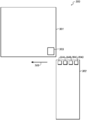
도 1은 연결가능한 컴포넌트 식별을 위한 제1 예시적인 시스템을 예시하는 블록도이다.
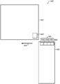
도 2는 연결가능한 컴포넌트 식별을 위한 제2 예시적인 시스템을 예시하는 블록도이다.
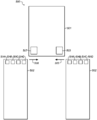
도 3은 연결가능한 컴포넌트 식별을 위한 제3 예시적인 시스템을 예시하는 블록도이다.
도 4는 연결가능한 컴포넌트 식별을 위한 제4 예시적인 시스템을 예시하는 블록도이다.
도 5는 연결가능한 컴포넌트 식별을 위한 제5 예시적인 시스템을 예시하는 블록도이다.
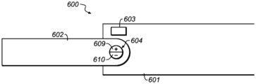
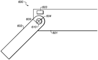
도 6a는 제1 연결 위치에서의 연결가능한 컴포넌트를 도시하는, 연결가능한 컴포넌트 식별을 위한 제6 예시적인 시스템을 예시하는 블록도이다.
도 6b는 제2 연결 위치에서의 연결가능한 컴포넌트를 도시하는 도 6a의 시스템을 예시한다.
도 7은 연결가능한 컴포넌트 식별을 위한 방법을 예시하는 방법도이다. 이 방법은 도 1 내지 도 6b의 시스템들에 의해 수행될 수 있다.
도 8은 도 1 내지 도 6b의 하우징들 내에 수용될 수 있는 전자 디바이스의 블록도이다.1 is a block diagram illustrating a first exemplary system for connectable component identification.
Figure 2 is a block diagram illustrating a second exemplary system for connectable component identification.
3 is a block diagram illustrating a third exemplary system for connectable component identification.
4 is a block diagram illustrating a fourth exemplary system for connectable component identification.
5 is a block diagram illustrating a fifth exemplary system for connectable component identification.
6A is a block diagram illustrating a sixth exemplary system for connectable component identification, showing connectable components at a first connected location.
Figure 6B illustrates the system of Figure 6A showing connectable components at a second connection position.
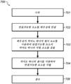
Figure 7 is a method diagram illustrating a method for identifying connectable components. This method can be performed by the systems of Figs. 1 to 6B.
8 is a block diagram of an electronic device that may be housed within the housings of Figs. 1 - 6B.
이어지는 설명은 본 개시내용의 다양한 요소들을 구현하는 예시적인 시스템, 방법, 및 컴퓨터 프로그램 제품을 포함한다. 그러나, 설명한 본 개시내용은 본 명세서에서 설명한 형태들에 부가하여 다양한 형태로 실행될 수 있음이 이해되어야 한다.The following description includes exemplary systems, methods, and computer program products embodying various elements of the present disclosure. It should be understood, however, that the described disclosure can be implemented in a variety of forms in addition to those described herein.
본 개시내용은 연결가능한 컴포넌트 식별을 위한 시스템 및 방법을 개시한다. 연결가능한 컴포넌트는 하우징에 연결될 수 있다. 하우징의 센서는 연결가능한 컴포넌트의 식별 요소를 검출하는 데 이용될 수 있다. 연결가능한 컴포넌트는 적어도 하나의 센서를 이용하여 식별될 수 있다.The present disclosure discloses systems and methods for connectable component identification. The connectable component may be connected to the housing. The sensor of the housing may be used to detect an identifiable element of a connectable component. Connectable components can be identified using at least one sensor.
일부 구현예들에서, 연결가능한 컴포넌트의 식별은 연결가능한 컴포넌트가 하우징에 연결되어 있는지의 여부를 식별할 수 있다.In some embodiments, identification of the connectable component may identify whether the connectable component is connected to the housing.
다른 구현예들에서, 연결가능한 컴포넌트의 식별은 연결되는 연결가능한 컴포넌트의 유형을 식별할 수 있다. 이러한 구현예들에서, 하우징은 전자 디바이스를 수용할 수 있고 전자 디바이스는 연결되는 연결가능한 컴포넌트의 유형에 기초하여 구성될 수 있다.In other implementations, the identification of a connectable component may identify the type of connectable component to which it is connected. In such embodiments, the housing may accommodate the electronic device and the electronic device may be configured based on the type of connectable component to which it is connected.
여전히 다른 구현예들에서, 연결가능한 컴포넌트의 식별은 연결가능한 컴포넌트가 위치설정된 위치를 식별할 수 있다. 이러한 구현예들에서, 하우징은 전자 디바이스를 수용할 수 있고 전자 디바이스는 연결가능한 컴포넌트가 연결되는 위치에 기초하여 구성될 수 있다.Still in other implementations, the identification of the connectable component may identify the location where the connectable component is located. In such embodiments, the housing can accommodate the electronic device and the electronic device can be configured based on the location to which the connectable component is connected.
일부 구현예들에서, 연결가능한 컴포넌트는 하나 이상의 워치 밴드(watch band)일 수 있다. 이러한 구현예들에서, 하우징은 하나 이상의 워치 본체를 포함할 수 있다. 그러나, 이는 예임을 이해해야 한다. 다른 구현예들에서, 연결가능한 컴포넌트는 임의의 종류의 하우징에 연결할 수 있는 임의의 종류의 컴포넌트, 예컨대, 모바일 컴퓨팅 디바이스에 연결하는 커넥터, 버클에 연결하는 벨트, 태블릿 컴퓨팅 디바이스에 연결하는 키보드 등을 포함할 수 있다.In some implementations, the connectable component may be one or more watch bands. In such embodiments, the housing may include one or more watch bodies. However, it should be understood that this is an example. In other implementations, connectable components include any type of component that can be coupled to any type of housing, such as a connector connecting to a mobile computing device, a belt connecting to a buckle, a keyboard connecting to a tablet computing device, .
다양한 구현예들에서, 식별 요소는 하나 이상의 자기 요소(예컨대, 영구 자석, 전자석 등)를 포함할 수 있고 센서는 적어도 하나의 홀 효과 센서(예컨대, 자계에 응답하여 그 출력 전압을 바꾸는 변환기)를 포함할 수 있다. 식별에 부가하여, 일부 경우들에서, 이러한 자기 요소들은 연결가능한 컴포넌트를 하우징에 연결하고/하거나 연결가능한 컴포넌트를 하우징으로부터 분리하는 데 이용되는 연결 메커니즘의 일부로서 이용될 수 있다.In various implementations, the identification element may include one or more magnetic elements (e.g., permanent magnets, electromagnets, etc.) and the sensor may include at least one Hall effect sensor (e.g., a transducer that changes its output voltage in response to a magnetic field) . In addition to identification, in some cases, these magnetic elements may be used as part of a connection mechanism used to connect the connectable component to the housing and / or separate the connectable component from the housing.
그러나, 다른 구현예들에서, 식별 요소는 자기 요소 이외의 요소일 수 있다. 일부 구현예들에서, 식별 요소는 적어도 하나의 근거리 무선 통신 수신기에 의해 검출가능한 적어도 하나의 근거리 무선 통신 송신기, 적어도 하나의 광학 검출기에 의해 검출가능한 적어도 하나의 착색 표시기, 적어도 하나의 바코드 판독기에 의해 검출가능한 적어도 하나의 바코드, 적어도 하나의 기계적 특징 검출기에 의해 검출가능한 적어도 하나의 기계적 특징부, 적어도 하나의 접촉부에 의해 검출가능한 적어도 하나의 전극, 적어도 하나의 적외 검출기에 의해 검출가능한 적어도 하나의 적외 방출기, 적어도 하나의 광 검출기에 의해 검출가능한 적어도 하나의 광 방출기, 및/또는 연결가능한 컴포넌트를 식별하는 데 이용될 수 있는 임의의 다른 이러한 요소일 수 있다.However, in other implementations, the identification element may be an element other than a magnetic element. In some embodiments, the identification element comprises at least one short range wireless communication transmitter detectable by the at least one short range wireless communication receiver, at least one color indicator detectable by the at least one optical detector, by at least one bar code reader At least one barcode, at least one mechanical feature detectable by at least one mechanical feature detector, at least one electrode detectable by at least one contact, at least one infrared detectable by at least one infrared detector An emitter, at least one optical emitter detectable by the at least one photodetector, and / or any other such element that can be used to identify a connectable component.
식별 요소가 다수의 자기 요소인 실시예들에서, 자기 요소들은 별개의 자기 요소들일 수 있다. 대안적으로, 자기 요소들은 더 큰 자기 요소의 개별 제어가능한 자기 표면들일 수 있다. 이러한 실시예들에서, 자기 요소들은 하나 이상의 홀 효과 센서에 의해 검출가능할 수 있는 하나 이상의 코드를 인코딩하도록 구성될 수 있다.In embodiments where the identification element is a plurality of magnetic elements, the magnetic elements may be separate magnetic elements. Alternatively, magnetic elements can be individually controllable magnetic surfaces of a larger magnetic element. In these embodiments, the magnetic elements may be configured to encode one or more codes that may be detectable by one or more Hall effect sensors.
일부 경우들에서, 연결가능한 컴포넌트는 하우징 내에 위치설정된 하나 이상의 홀 효과 센서를 향한 방향으로 연결가능한 컴포넌트를 이동시킴으로써 하우징에 연결될 수 있다. 이러한 경우들에서, 다수의 홀 효과 센서들은 각각이 자기 요소들 중 하나를 검출하는 데 이용될 수 있으므로, 연결가능한 컴포넌트를 식별하는 데 이용될 수 있는 그 내에 인코딩된 코드를 협력하여 검출할 수 있다.In some cases, the connectable component can be connected to the housing by moving a component connectable in a direction towards one or more Hall effect sensors positioned within the housing. In such cases, multiple Hall effect sensors can be used to detect one of the magnetic elements, respectively, and thus can cooperatively detect the encoded code within it that can be used to identify the connectable component .
다른 경우들에서, 연결가능한 컴포넌트는 하우징 내에 위치설정된 하나 이상의 홀 효과 센서에 평행한 방향으로 연결가능한 컴포넌트를 이동시킴으로써 하우징에 연결될 수 있다. 예를 들면, 홀 효과 센서는 하우징의 코너에 위치설정될 수 있고, 연결가능한 컴포넌트를 연결하는 동안 연결가능한 컴포넌트가 홀 효과 센서에 평행하게 이동됨에 따라 자기 요소들 각각을 검출할 수 있다(따라서 연결가능한 컴포넌트를 식별하는 데 이용될 수 있는 그 내에 인코딩된 코드를 검출함).In other cases, the connectable component can be connected to the housing by moving a connectable component in a direction parallel to the one or more Hall effect sensors positioned within the housing. For example, the Hall effect sensor can be positioned at the corners of the housing, and while connecting connectable components can detect each of the magnetic elements as the connectable component is moved parallel to the Hall effect sensor Lt; RTI ID = 0.0 > code < / RTI > within it that can be used to identify a possible component).
다른 예로서, 홀 효과 센서는 하우징의 대향하는 코너에 위치설정될 수 있다. 이러한 예에서, 연결가능한 컴포넌트는 두 개의 홀 효과 센서 중 어느 하나가 다른 홀 효과 센서를 향하여 홀 효과 센서에 평행한 방향으로 위치된 코너로부터 연결가능한 컴포넌트를 이동시킴으로써 연결될 수 있다. 따라서, 그 홀 효과 센서는 각각의 자기 요소들을 각각 검출할 수 있으므로, 연결가능한 컴포넌트를 식별하는 데 이용될 수 있는 그 내에 인코딩된 코드를 검출할 수 있다.As another example, the Hall effect sensor may be positioned at the opposite corner of the housing. In this example, the connectable component can be connected by moving a connectable component from a corner where one of the two Hall effect sensors is positioned in a direction parallel to the Hall effect sensor towards the other Hall effect sensor. Thus, the hall effect sensor can detect each magnetic element individually, and thus can detect the encoded code within it that can be used to identify a connectable component.
다양한 구현예들에서, 센서는 하우징 내에 완전히 봉입될 수 있다. 이러한 일부 구현예들에서, 하우징은 방수가 될 수 있다. 그러나, 다른 구현예들에서, 센서는 하우징의 적어도 하나의 외부 표면 상에 적어도 부분적으로 위치설정될 수 있다.In various embodiments, the sensor may be completely enclosed within the housing. In some of these embodiments, the housing may be watertight. However, in other embodiments, the sensor may be positioned at least partially on at least one outer surface of the housing.
도 1은 연결가능한 컴포넌트 식별을 위한 제1 예시적인 시스템(100)을 예시하는 블록도이다. 예시된 바와 같이, 시스템은 하우징(101), 및 하우징에 연결될 수 있는 연결가능한 컴포넌트(102)를 포함할 수 있다. 이러한 예에서, 연결가능한 컴포넌트는 하우징을 향한 방향(105)으로 연결가능한 컴포넌트를 이동시킴으로써 하우징에 연결될 수 있다.1 is a block diagram illustrating a first
예시된 바와 같이, 하우징(101)은 워치 본체이고 연결가능한 컴포넌트는 워치 밴드(102)이다. 그러나, 이는 예임을 이해해야 한다. 다양한 구현예들에서, 하우징은 워치 본체 이외의 아이템(예컨대, 랩톱 컴퓨팅 디바이스, 데스크톱 컴퓨팅 디바이스, 모바일 컴퓨팅 디바이스, 태블릿 컴퓨팅 디바이스, 스마트 폰, 셀룰러 전화기, 디지털 미디어 재생기, 버클, 착용가능한 디바이스, 및/또는 임의의 다른 이러한 아이템)일 수 있고 연결가능한 컴포넌트는 그에 연결가능한 임의의 컴포넌트(예컨대, 커넥터, 키보드, 커버, 외부 디바이스, 및/또는 임의의 다른 이러한 연결가능한 컴포넌트)일 수 있다.As illustrated, the
하우징(101)은 하나 이상의 센서(103)를 포함할 수 있다. 또한, 연결가능한 컴포넌트(102)는 하나 이상의 식별 요소(104)를 포함할 수 있다. 연결가능한 컴포넌트가 하우징에 연결되는 경우, 센서는 식별 요소를 검출할 수 있다. 식별 요소의 검출에 적어도 기초하여, 연결가능한 컴포넌트는 식별될 수 있다.The
예를 들면, 식별 요소(104)는 하나 이상의 자기 요소(예컨대, 하나 이상의 영구 자석, 전자석 등)일 수 있다. 이러한 예에서, 센서(103)는 하나 이상의 홀 효과 센서일 수 있다. 연결가능한 컴포넌트(102)가 하우징(101)에 연결되는 경우, 홀 효과 센서는 자기 요소를 검출할 수 있다.For example, identification element 104 may be one or more magnetic elements (e.g., one or more permanent magnets, electromagnets, etc.). In this example, the
일부 경우들에서, 센서(103)는 연결가능한 컴포넌트가 연결되어 있는지의 여부를 검출함으로써 연결가능한 컴포넌트(102)를 식별할 수 있다. 따라서, 센서는 홀 효과 센서이고 식별 요소(104)가 자기 요소인 경우, 자기 요소를 검출하는 홀 효과 센서는 일부 유형의 연결가능한 컴포넌트가 연결됨을 식별할 수 있다.In some cases, the
하우징(101)이 전자 디바이스를 수용하는 경우들에서, 전자 디바이스는 연결가능한 컴포넌트(102)가 연결되는 경우인 하나의 방식으로 그리고 연결가능한 컴포넌트가 연결되지 않은 경우인 다른 방식으로 그 자신을 구성할 수 있다. 예를 들면, 전자 디바이스는, 연결가능한 컴포넌트가 연결되는 경우 스크린 상에 "연결가능한 컴포넌트 연결됨" 아이콘, 및 연결가능한 컴포넌트가 연결되지 않은 경우 스크린 상에 "연결가능한 컴포넌트 연결되지 않음" 아이콘을 표시할 수 있다.In the case where the
다른 경우들에서, 센서(103)는 식별 요소(104)에 의해 인코딩된 하나 이상의 코드를 검출함으로써 연결가능한 컴포넌트(102)를 식별할 수 있다. 본 예에서, 식별 요소는 단일의 자기 요소일 수 있다. 그러나, 단일의 자기 요소도 다양한 유형의 밴드들에 대응하는 코드들을 인코딩할 수 있다. 예를 들면, 자기 요소는 "업무용" 유형의 연결가능한 컴포넌트를 위해 양으로(예를 들면, + 또는 "북") 극성이 부여된 표면, "가정용" 유형의 연결가능한 컴포넌트를 위해 음으로(예를 들면, - 또는 "남") 극성이 부여된 표면, 및 "스포츠용" 유형의 연결가능한 컴포넌트를 위해 양으로 극성이 부여된 표면과 음으로 극성이 부여된 표면의 조합을 나타내도록 구성될 수 있다. 따라서, 연결가능한 컴포넌트가 업무용, 가정용 또는 스포츠용인지의 여부는 홀 효과 센서에 의해 검출된 표면의 극성에 기초하여 식별될 수 있다.In other instances, the
전자 디바이스가 하우징(101) 내에 수용되는 경우들에서, 전자 디바이스는 제1 유형의 연결가능한 컴포넌트(102)가 연결되는 경우인 하나의 방식으로 그리고 제2 유형의 연결가능한 컴포넌트가 연결되는 경우인 다른 방식으로 그 자신을 구성할 수 있다. 예를 들면, 전자 디바이스가 워치인 구현예들에서, 전자 디바이스는 업무용 유형의 연결가능한 컴포넌트가 부착되는 경우 24시간 시간 형식의 시간 및 계산기 애플리케이션, 가정용 유형의 연결가능한 컴포넌트가 부착되는 경우 12시간 형식의 시간, 및 스포츠용 유형의 연결가능한 컴포넌트가 부착되는 경우 스톱워치 애플리케이션을 표시할 수 있다. 연결가능한 컴포넌트의 유형이 스위치들을 검출한 경우, 전자 디바이스는 그에 맞춰 그 자신을 재구성할 수 있다.In the case where the electronic device is housed within the
여전히 다른 예에서, 태블릿 컴퓨팅 디바이스는 하우징(101) 내에 수용될 수 있고, 키보드 또는 커버 유형의 연결가능한 컴포넌트(102)가 연결될 수 있다. 이러한 경우에서, 태블릿 컴퓨팅 디바이스는, 키보드 연결가능한 컴포넌트 유형이 연결되는 경우 워드 프로세싱 애플리케이션을 표시하고 커버 연결가능한 컴포넌트 유형이 연결되는 경우 그 자신이 전력 대기 상태(power hibernation state)로 들어가도록 그 자신을 구성할 수 있다.Still in another example, the tablet computing device may be housed within the
연결가능한 컴포넌트(102)는 도시되지 않은 다양한 상이한 연결 메커니즘을 통해 하우징(101)에 연결될 수 있다. 예를 들면, 연결가능한 컴포넌트 및/또는 하우징은, (예컨대, 하우징으로부터 연결가능한 컴포넌트를 리펄스(repulse)하도록 자석들의 극성을 역전하는 버튼을 누름으로써) 방향(105)으로 함께 가져오는 경우 연결가능한 컴포넌트 및 하우징에 연결하기 위해 자기적으로 부착하고/하거나 연결가능한 컴포넌트 및 하우징을 분리하기 위해 탈착할 수 있는 하나 이상의 자기 강성(영구 자석) 또는 연성(자기는 아니지만 자화된 요소들의 근접성에 응답하게 될 수 있는 강자성 금속과 같은 재료들)을 포함할 수 있다. 다른 예에 의해, 연결가능한 컴포넌트 및/또는 하우징은 집어넣을 수 있는 핀들 및 집어넣을 수 있는 핀들이 삽입될 수 있는 개구들과 같은 하나 이상의 기계적 부착 메커니즘을 포함할 수 있다.The
이용된 연결 메커니즘의 유형에 상관 없이, 일부 경우들에서, 식별 요소(104)는 연결 메커니즘의 일부일 수 있다. 예를 들면, 자기 연결 메커니즘이 이용되고 식별 요소가 적어도 하나의 자기 요소인 구현예들에서, 식별 요소는 하우징(101)의 강성 및/또는 연성 자기 요소에 자기적으로 부착하도록 동작가능할 수 있다. 기계적 연결 메커니즘이 이용되고 식별 요소가 자기 요소인 경우들에서, 자기 요소는 기계적 연결을 체결하기 위한 목적으로 하우징(101)에 대하여 연결가능한 요소(102)를 위치설정하는 것을 도울 수 있다.Regardless of the type of connection mechanism used, in some cases, the identification element 104 may be part of a connection mechanism. For example, in embodiments where a magnetic connection mechanism is utilized and the identification element is at least one magnetic element, the identification element may be operable to magnetically attach to the rigid and / or soft magnetic element of the
도 2는 연결가능한 컴포넌트 식별을 위한 제2 예시적인 시스템(200)을 예시하는 블록도이다. 본 예를 도 1의 예와 비교하면, 본 예의 센서는 복수의 센서(203A 내지 203D)이며, 식별 요소는 복수의 식별 요소(204A 내지 204D)이다. 본 예에서, 연결가능한 요소(202)가 방향(205)으로 하우징(201)을 향해 가져와지는 경우, 복수의 센서 각각은 복수의 식별 요소 중 개별 식별 요소를 검출한다. 이러한 방식에서, 복수의 식별 요소의 배열은 연결가능한 컴포넌트의 유형을 표현할 수 있는 하나 이상의 코드를 인코딩한다.2 is a block diagram illustrating a second
예를 들면, 복수의 식별 요소(204A 내지 204D)는 자기 요소들일 수 있고, 복수의 센서(203A 내지 203D)는 복수의 홀 효과 센서일 수 있다. 이러한 예에서, 복수의 식별 요소는 복수의 홀 효과 센서를 마주보는 복수의 식별 요소의 극성들에 기초하여 상이한 연결가능한 컴포넌트(202) 유형을 표현할 수 있다. "++++"의 극성 패턴은 제1 유형의 밴드를 표현할 수 있고 "----"의 극성 패턴은 제2 유형의 밴드를 표현할 수 있다. 게다가, "+-+-"의 패턴은 제3 유형의 밴드를 표현할 수 있고, "-+--"의 패턴은 제4 유형의 밴드를 표현할 수 있고, 그 외에도 있을 수 있으며, 여기서 +는 양의 극성을 의미하고 -는 음의 극성을 의미한다.For example, the plurality of
또한, 상기 예들이 하나의 극성 또는 홀 효과 센서를 마주보는 다른 극성을 설명하지만, 이는 예임을 이해해야 한다. 다양한 경우들에서, 각 극성의 하나 이상의 부분은 홀 효과 센서를 마주보고 그에 의해 검출될 수 있다.It should also be understood that the above examples illustrate other polarities facing one polarity or Hall effect sensor, but this is an example. In various instances, one or more portions of each polarity may be detected by the Hall effect sensor.
도 3은 연결가능한 컴포넌트 식별을 위한 제3 예시적인 시스템(300)을 예시하는 블록도이다. 본 예를 도 2의 예와 비교하면, 본 예의 센서는 하우징(301)의 코너에 위치설정된 단일의 센서(303)이며, 연결가능한 요소(302)는 센서가 방향(305)을 따라 대향하는 코너에 위치되는 하우징의 코너로부터 센서에 평행한 방향(305)으로 이동함으로써 하우징에 연결한다. 연결가능한 요소는 하우징에 연결되어 있음에 따라, 다양한 식별 요소들(304A 내지 304D)은 방향(305)에 따라 센서(303)를 순차적으로 통과할(그리고 그에 의해 검출될) 수 있다. 따라서, 식별 요소들은 연결가능한 요소의 유형을 표현하는 코드를 인코딩하도록 구성될 수 있고 연결 동안 단일의 센서에 의해 검출될 수 있다.3 is a block diagram illustrating a third
연결가능한 컴포넌트(302)는 도시되지 않은 다양한 상이한 연결 메커니즘을 통해 하우징(301)에 연결될 수 있다. 예를 들면, 연결가능한 컴포넌트 및/또는 하우징은 하우징에 연결가능한 컴포넌트를 연결하기 위하여 하나 이상의 튜브로 삽입(및/또는 연결가능한 컴포넌트를 하우징으로부터 분리하기 위하여 튜브들로부터 제거)되는 하나 이상의 로드(rod)를 포함할 수 있다.The
도 4는 연결가능한 컴포넌트 식별을 위한 제4 예시적인 시스템(400)을 예시하는 블록도이다. 본 예를 도 3의 예와 비교하면, 식별 요소들(406A 내지 406D)은 도 3의 별개의 그리고 이격된 식별 요소들(303A 내지 303D)에 대향됨에 따라 조합된 식별 요소(4)의 개별 제어가능한 표면들일 수 있다. 식별 요소들(406A 내지 406D)이 자기 요소들인 구현예들에서, 식별 요소들(406A 내지 406D)은 개별 제어가능한 자기 요소들일 수 있다.4 is a block diagram illustrating a fourth
도 5는 연결가능한 컴포넌트 식별을 위한 제5 예시적인 시스템(500)을 예시하는 블록도이다. 본 예를 도 3의 예와 비교하면, 추가 센서(507)가 센서(503)로부터 대향하는 코너에 위치될 수 있다. 또한, 본 예에서, 연결가능한 컴포넌트(501)는 센서(503)가 위치된 코너로부터 센서(507)가 위치된 코너로의 방향(505)으로 연결가능한 요소를 이동시키거나 센서(507)가 위치된 코너로부터 센서(503)가 위치된 코너로의 방향(508)으로 연결가능한 요소를 이동시킴으로써 하우징에 연결될 수 있다. 이러한 방식에서, 연결가능한 컴포넌트는 어느 하나의 측면으로부터 연결될 수 있고 연결가능한 컴포넌트는 여전히 식별될 수 있다.5 is a block diagram illustrating a fifth
일부 경우들에서, 센서들(503, 507)에 의해 수행된 검출은, 연결가능한 컴포넌트(502)가 하우징(501)에 연결되는 경우 센서들(503, 507)이 상이한 순서로 식별 요소들(504A-504D)에 마주칠 것이므로 상이하게 취급될 수 있다. 일부 경우들에서, 식별 요소들에 의해 인코딩된 코드들은 동일한 순방향 및 역방향일 수 있어, 센서 검출의 분석은 센서(503, 507) 둘 다에 대해 동일할 수 있다. 예를 들면, 식별 요소들이 자기 요소들인 경우, "++--" 및 "--++"의 패턴들은 둘 다 업무용 연결가능한 요소를 나타낼 수 있는 반면 "-+-+" 및 "+-+-"의 패턴들은 둘 다 가정용 연결가능한 요소를 나타낼 수 있다.In some cases the detection performed by the
그러나, 다른 경우들에서, 센서(503)에 의해 수행된 센서 검출은 식별 요소들이 더 큰 수의 코드들을 인코딩할 수 있도록 센서(507)의 그것과 반대로 분석될 수 있다. 예를 들면, 식별 요소들이 자기 요소들인 경우에서, "++--"의 패턴이 센서(503)에 의해 검출되는 경우 업무용 연결가능한 요소를 나타낼 수 있지만, "++--"의 패턴이 센서(507)에 의해 검출되는 경우 가정용 연결가능한 요소를 나타낼 수 있다. 또한, "--++"의 패턴이 센서(503)에 의해 검출되는 경우 가정용 연결가능한 요소를 나타낼 수 있지만, "--++"의 패턴이 센서(507)에 의해 검출되는 경우 업무용 연결가능한 요소를 나타낼 수 있다.However, in other cases, the sensor detection performed by the
또한, 도 1 내지 도 5의 상기 논의는 업무용, 가정용, 및/또는 스포츠용과 같은 유형을 나타내거나 나타내지 않으므로 연결가능한 컴포넌트들을 식별하는 것을 논의하지만, 이들은 예들임을 이해해야 한다. 다른 연결가능한 컴포넌트 유형들이 식별될 수 있고 연결된 하우징에 의해 수용된 전자 디바이스는 그에 맞춰 변경될 수 있다. 예를 들면, 연결가능한 컴포넌트는 전자 디바이스 또는 서드 파티(third party)로서 동일한 제조업자에 의해 제조된 것으로 식별될 수 있다. 따라서, 전자 디바이스는 제조업자의 연결가능한 컴포넌트가 연결되는 경우 소정 추가 기능들(예컨대, 오피스 프로그램)을 인에이블하고 서드 파티 컴포넌트가 브랜드 로열티를 보상하도록 연결되는 경우 이러한 기능들을 디스에이블할 수 있다.It should also be understood that the above discussion of Figures 1-5 discusses identifying connectable components since they do not represent or represent types such as business, home, and / or sport, but these are examples. Other connectable component types may be identified and the electronic device accommodated by the connected housing may be modified accordingly. For example, connectable components may be identified as being manufactured by the same manufacturer as an electronic device or a third party. Accordingly, the electronic device may disable some of these functions if the manufacturer's connectable components are connected to enable some additional functions (e.g., office programs) and the third party components are connected to compensate for brand loyalty.
다른 예에 의해, 연결가능한 컴포넌트들은 하우징에 의해 수용된 전자 디바이스를 위한 전력 모드 또는 전력 모드들의 세트, 하우징에 의해 수용된 전자 디바이스에 이용하기 위한 통신 설정, 그를 위해 하우징에 의해 수용된 전자 디바이스가 구성되는 사용자, 및/또는 다양한 상이한 표시를 나타내는 유형일 수 있다. 본질적으로, 연결가능한 컴포넌트를 식별하는 것은 연결가능한 컴포넌트의 유형에 의해 상징되는 임의의 종류의 정보의 하나 이상의 아이템을 식별할 수 있고, 하우징에 의해 수용된 전자 디바이스는 그러한 정보에 기초하여 임의의 종류의 구성 또는 수정을 수행할 수 있다. 정보에 응답한 이러한 구성 또는 수정은, 특정 연결가능한 컴포넌트가 연결되는 경우 수행될 하나 이상의 사용자 선호의 구성들, 수정들, 및/또는 변경을 사용자가 특정할 수 있게 하는 일부 경우들에서 사용자 구성될 수 있다. 그와 관계없이, 본 명세서에서 주어진 예들은 예들이고 제한하는 것으로 의도되지 않는다.By another example, connectable components include a set of power modes or power modes for an electronic device received by the housing, a communication setting for use with the electronic device accommodated by the housing, a user for which the electronic device accommodated by the housing is configured , ≪ / RTI > and / or a variety of different indicia. Essentially, identifying a connectable component may identify one or more items of any kind of information represented by the type of connectable component, and the electronic device received by the housing may identify any kind of information Configuration or modification. Such configuration or modification in response to the information may be user configurable in some instances that allows the user to specify configurations, modifications, and / or changes of one or more user preferences to be performed when certain connectable components are connected . Regardless, the examples given herein are illustrative and are not intended to be limiting.
예를 들면, 컴퓨팅 디바이스는 하우징 내에 수용될 수 있다. 표시가 금속성 연결가능한 컴포넌트가 부착됨을 나타내는 경우, 컴퓨팅 디바이스는 그 자신을 금속성 아이콘들(및/또는 사용자 인터페이스의 테마, 등)을 나타내도록 구성할 수 있다. 유사하게, 특정 색상의 밴드가 부착되는 경우, 컴퓨팅 디바이스는 그 자신을 특정 색상(및/또는 특정 색상의 백그라운드 색상 등)의 아이콘들을 나타내도록 구성할 수 있다. 또는, 다른 예로서, 실리콘 밴드가 부착되는 경우, 컴퓨팅 디바이스는 "홈" 스크린 상에 아이콘들에 관련된 하나 이상의 스포츠 애플리케이션을 나타내고/내거나 이러한 애플리케이션들을 실행에 이용가능하게 만들도록 그 자신을 구성할 수 있다.For example, the computing device may be housed within the housing. If the indication indicates that a metallic connectable component is attached, the computing device may configure itself to represent the metallic icons (and / or the theme of the user interface, etc.). Similarly, when a band of a particular color is attached, the computing device may configure itself to represent icons of a particular color (and / or a background color of a particular color, etc.). Alternatively, as another example, when a silicon band is attached, the computing device may configure itself to represent and / or render one or more sports applications associated with icons on a "home" screen have.
또한, 도 1 내지 도 5의 상기 논의가 식별 요소들이 양의 또는 음의 극성을 가지므로 홀 효과 센서를 마주보는 자기 요소의 표면을 구성함으로써 코드들을 인코딩하는 자기 요소들인 실시예들을 논의하지만, 이는 예임을 이해해야 한다. 이러한 자기 요소들은 본 개시내용의 범주를 벗어나지 않으면서 단일 극성 표면이나 극성 표면들 둘 다의 특정 배향을 갖도록 구성될 수 있다. 또한, 이러한 자기 요소들은 정보가 자계가 강함 또는 약함; 강함, 중간 또는 약함; 다양한 정도의 강도 등의 여부로 인코딩되도록 자계의 특정 강도로 구성될 수 있다. 추가적으로, 일부 자기 요소들은 자계가 없도록(또는 "널(null)") 구성될 수 있고 자계의 부족을 통해 정보를 인코딩할 수 있다. 추가적으로, (예컨대, 자기 요소들 중 하나 이상은 전자석인) 일부 경우들에서, 자기 요소들의 자계는 패턴을 나타내고, 하나 이상의 코드를 펄스(pulse)하고/하거나, 자계를 변경함으로써 이러한 다른 기능들을 수행하도록 시간이 지남에 따라 변할 수 있다.In addition, while the above discussion of Figures 1 to 5 discuss embodiments that are magnetic elements that encode codes by constructing the surface of the magnetic element facing the Hall effect sensor since the identification elements have a positive or negative polarity, You must understand that it is an example. These magnetic elements may be configured to have a particular orientation of both the single polar or polar surfaces without departing from the scope of the present disclosure. In addition, these magnetic elements may be magnetic fields whose information is strong or weak; Strong, moderate or weak; And may be configured to have a specific strength of the magnetic field so as to be encoded with various degrees of strength or the like. Additionally, some magnetic elements may be configured to have no magnetic field (or "null") and may encode information through lack of a magnetic field. Additionally, in some instances (e.g., where one or more of the magnetic elements is an electromagnet), the magnetic field of the magnetic elements represents a pattern, pulses one or more of the codes and / or performs these other functions It can change over time.
추가적으로, 도 1 내지 도 5에 예시된 다양한 센서들 및 식별 요소들은 도 1 내지 도 5의 다양한 하우징들 또는 연결가능한 컴포넌트들 내에 봉입되는 것으로서 각각 예시된다. 예시된 바와 같이, 하우징 및/또는 연결가능한 요소들은 외부 환경으로부터 다양한 센서들 및 식별 요소들을 보호할 수 있으면서, 다양한 센서들은 여전히 다양한 식별 요소들을 검출할 수 있다. 일부 경우들에서, 하우징들 및/또는 연결가능한 요소들은 방수되는 것, 기밀하게 밀봉되는 것 등 일 수 있으므로, 다양한 센서들 및 식별 요소들을 더 보호할 수 있다.Additionally, the various sensors and identification elements illustrated in Figs. 1-5 are each illustrated as being encapsulated within the various housings or connectable components of Figs. 1-5. As illustrated, the housing and / or connectable elements can protect various sensors and identification elements from the external environment, while the various sensors can still detect various identification elements. In some cases, the housings and / or connectable elements may be watertight, hermetically sealed, etc., thus further protecting the various sensors and identification elements.
그러나, 이들은 예임을 이해해야 한다. 다양한 구현예들에서, 다양한 센서들 및/또는 식별 요소들은 본 개시내용의 범주를 벗어나지 않으면서 다양한 하우징들 및/또는 연결가능한 요소들에 부분적으로 노출되고/되거나 완전히 외부에 있을 수 있다. 일부 구현예들에서, 센서들 및/또는 식별 요소들이 하우징 및/또는 식별 요소에 의해 분리되면 센서들은 식별 요소들을 검출할 수 없는 유형들일 수 있다.However, it should be understood that these are examples. In various implementations, the various sensors and / or identification elements may be partially exposed and / or completely external to the various housings and / or connectable elements without departing from the scope of the present disclosure. In some embodiments, the sensors may be of the types in which the identification elements can not be detected if the sensors and / or the identification elements are separated by the housing and / or the identification element.
또한, 연결가능한 컴포넌트의 존재 또는 부재 및 연결된 연결가능한 컴포넌트의 유형에 부가하여, 연결된 컴포넌트는 다수의 위치들 간에 이동가능할 수 있고, 연결가능한 컴포넌트를 식별하는 것은 연결가능한 컴포넌트가 연결된 위치에서 식별하는 것을 포함할 수 있다.Also, in addition to the presence or absence of a connectable component and the type of connectable component that is connected, the connected component may be movable between multiple locations, and identifying the connectable component may include identifying .
예를 들면, 도 6a는 하우징(601)에 대하여 제1 연결 위치에서의 연결가능한 컴포넌트(602)를 도시하는, 연결가능한 컴포넌트 식별을 위한 제6 예시적인 시스템(600)을 예시하는 블록도이다. 이러한 제1 위치에서, 센서(603)는 식별 요소(604)의 배향을 검출하여 연결가능한 컴포넌트가 제1 위치에 있음을 결정할 수 있다.For example, FIG. 6A is a block diagram illustrating a sixth
도 6b는 하우징(601)에 대하여 제2 연결 위치에서의 연결가능한 컴포넌트(602)를 도시하는 도 6a의 시스템을 예시한다. 예시된 바와 같이, 제1 위치로부터 제2 위치로의 연결가능한 컴포넌트의 이동은 식별 요소(604)를 회전한다. 센서(603)는 식별 요소의 배향의 변경을 검출하여 연결가능한 컴포넌트가 제2 위치에 있음을 결정할 수 있다.6B illustrates the system of FIG. 6A showing a
하우징(601) 및/또는 그 내에 수용된 전자 디바이스는 연결가능한 컴포넌트가 제1 위치 또는 제2 위치(및/또는 다른 실시예들에서의 추가 위치들)에 있는지 여부에 기초하여 변경할 수 있다. 예를 들면, 하우징은 디스플레이를 구비한 워치용 하우징일 수 있다. 연결가능한 컴포넌트(602)는, 워치가 "비착용"된 경우 제1 위치에, 및 워치가 "착용"된 경우 제2 위치에 있을 수 있다. 따라서, 워치는 사용자가 시간을 볼 필요가 없다는 가정 하에 디스플레이를 어둡게 함으로써 워치가 착용되지 않는 경우 "저전력 모드"로 이동할 수 있다. 반대로, 워치는 사용자가 워치를 착용하고 있는 경우 시간을 볼 필요가 있을 수 있다는 가정 하에 디스플레이를 밝게 함으로써 워치가 착용된 경우 "정상 전력 모드"로 이동할 수 있다.The
예시된 바와 같이, 본 실시예에서 식별 요소(604)는 제1 위치에서 홀 효과 센서(603)에 양의 극성 표면, 및 제2 위치에서 양의 그리고 음의 극성 표면들의 조합을 나타내기 위해 제1 위치로 배향된 자기 요소이다. 그러나, 이는 예임을 이해해야 한다. 다른 구현예들에서, 식별 요소는 다양한 상이한 종류의 식별 요소들일 수 있고/있거나 센서는 본 개시내용의 범주를 벗어나지 않으면서 식별 요소들의 배향을 검출하도록 동작가능한 다양한 상이한 종류의 센서들일 수 있다.As illustrated, the
도 7은 연결가능한 컴포넌트 식별을 위한 방법을 예시하는 방법도이다. 이 방법은 도 1 내지 도 6b의 시스템들에 의해 수행될 수 있다.Figure 7 is a method diagram illustrating a method for identifying connectable components. This method can be performed by the systems of Figs. 1 to 6B.
흐름은 블록(701)에서 시작하고 연결가능한 요소가 하우징에 연결되는 블록(702)으로 진행한다. 이어서, 흐름은 하우징의 적어도 하나의 센서가 연결가능한 요소의 적어도 하나의 식별 요소를 검출하는 데 이용되는 블록(703)으로 진행한다. 이어서, 흐름은 블록(704)으로 진행한다.The flow begins at
블록(704)에서, 연결가능한 요소는 적어도 하나의 센서를 이용하여 식별된다. 식별은 식별 요소의 센서들 검출에 적어도 부분적으로 기초할 수 있다. 이어서, 흐름은 블록(705)으로 진행하고 종료한다.At
도 8은 도 1 내지 도 6b의 하우징들 내에 수용될 수 있는 전자 디바이스(801)의 블록도이다. 전자 디바이스는 임의의 종류의 전자 디바이스일 수 있고, 하나 이상의 프로세싱 유닛(811), 하나 이상의 통신 컴포넌트(813)(WiFi 통신 컴포넌트, 블루투스 통신 컴포넌트, 이더넷 통신 컴포넌트, 위성 통신 컴포넌트, 셀룰러 통신 컴포넌트 등과 같은 임의의 종류의 통신 컴포넌트일 수 있음), 하나 이상의 센서(803)(임의의 종류의 센서들일 수 있음), 및/또는 하나 이상의 비일시적 저장 매체(812)(자기 저장 매체; 광학 저장 매체; 광자기 저장 매체; 판독 전용 메모리; 랜덤 액세스 메모리; 소거가능 프로그램가능한 메모리; 플래시 메모리 등의 형태를 취할 수 있지만, 이에 제한되지 않음)를 포함할 수 있다.8 is a block diagram of an
추가적으로, 전자 디바이스(801)는 도시된 컴포넌트들 이외에 하나 이상의 다른 컴포넌트를 포함할 수 있다. 일부 실시예들에서, 프로세싱 유닛(811)은 비일시적 저장 매체(812)에 저장된 하나 이상의 명령어를 실행하여 하나 이상의 전자 디바이스 기능을 수행할 수 있다. 이러한 기능들은 상기 설명하고 도 7에 예시된 기능들과 같은 기능들을 포함할 수 있다.Additionally, the
상기 설명하고 첨부 도면에 예시된 바와 같이, 본 개시내용은 연결가능한 컴포넌트 식별을 위한 시스템들 및 방법들을 개시한다. 연결가능한 컴포넌트는 하우징에 연결될 수 있다. 하우징의 센서는 연결가능한 컴포넌트의 식별 요소를 검출하는 데 이용될 수 있다. 연결가능한 컴포넌트는 적어도 하나의 센서를 이용하여 식별될 수 있다.As described above and illustrated in the accompanying drawings, this disclosure discloses systems and methods for connectable component identification. The connectable component may be connected to the housing. The sensor of the housing may be used to detect an identifiable element of a connectable component. Connectable components can be identified using at least one sensor.
일부 구현예들에서, 연결가능한 컴포넌트의 식별은 연결가능한 컴포넌트들이 하우징에 연결되어 있는지의 여부를 식별할 수 있다. 다른 구현예들에서, 연결가능한 컴포넌트의 식별은 연결되는 연결가능한 컴포넌트의 유형을 식별할 수 있다. 이러한 구현예들에서, 하우징은 전자 디바이스를 수용할 수 있고 전자 디바이스는 연결되는 연결가능한 컴포넌트의 유형에 기초하여 구성될 수 있다. 여전히 다른 구현예들에서, 연결가능한 컴포넌트의 식별은 연결가능한 컴포넌트가 위치설정된 위치를 식별할 수 있다. 이러한 구현예들에서, 하우징은 전자 디바이스를 수용할 수 있고 전자 디바이스는 연결가능한 컴포넌트가 연결되는 위치에 기초하여 구성될 수 있다.In some implementations, identification of a connectable component may identify whether connectable components are coupled to the housing. In other implementations, the identification of a connectable component may identify the type of connectable component to which it is connected. In such embodiments, the housing may accommodate the electronic device and the electronic device may be configured based on the type of connectable component to which it is connected. Still in other implementations, the identification of the connectable component may identify the location where the connectable component is located. In such embodiments, the housing can accommodate the electronic device and the electronic device can be configured based on the location to which the connectable component is connected.
본 개시내용에서, 설명한 방법들은 디바이스에 의해 판독가능한 명령어들의 세트들 또는 소프트웨어로서 구현될 수 있다. 또한, 개시된 방법들에서 단계들의 특정 순서 또는 계층은 예시적인 접근의 예들임을 이해해야 한다. 다른 실시예들에서, 방법에서 단계들의 특정 순서 또는 계층은 개시된 대상 내에 남아있으면서 재배열될 수 있다. 첨부 방법 청구항들은 예시적인 순서로 다양한 단계들의 요소들을 나타내고, 나타낸 특정 순서 또는 계층에 제한되는 것을 필수적으로 의미하지 않는다.In the present disclosure, the methods described may be implemented as sets of instructions or software readable by a device. It should also be understood that the particular order or hierarchy of steps in the disclosed methods is an example of an exemplary approach. In other embodiments, the particular order or hierarchy of steps in the method may be rearranged while remaining within the disclosed subject matter. Attachment Method Claims represent elements of the various steps in an exemplary order and are not necessarily meant to be limited to the particular order or hierarchy indicated.
설명한 개시내용은 그에 저장된 명령어들을 갖는 비일시적 기계 판독가능한 매체를 포함할 수 있는 컴퓨터 프로그램 제품 또는 소프트웨어로서 제공될 수 있고, 이는 본 개시내용에 따른 프로세스를 수행하기 위해 컴퓨터 시스템(또는 다른 전자 디바이스들)을 프로그래밍하는 데 사용될 수 있다. 비일시적 기계 판독가능한 매체는 기계(예컨대, 컴퓨터)에 의해 판독가능한 형태(예컨대, 소프트웨어, 프로세싱 애플리케이션)로 정보를 저장하기 위한 임의의 메커니즘을 포함한다. 비일시적 기계 판독가능한 매체는 자기 저장 매체(예컨대, 플로피 디스켓, 비디오 카세트 등); 광학 저장 매체(예컨대, CD-ROM); 광자기 저장 매체; 판독 전용 메모리(ROM); 랜덤 액세스 메모리(RAM); 소거가능 프로그램가능한 메모리(예컨대, EPROM 및 EEPROM); 플래시 메모리 등의 형태를 취할 수 있지만 이에 제한되지 않는다.The disclosed disclosure may be provided as a computer program product or software that may include a non-volatile machine-readable medium having instructions stored thereon, which may be stored on a computer system (or other electronic device ). ≪ / RTI > Non-volatile machine-readable media include any mechanism for storing information in a form readable by a machine (e.g., a computer) (e.g., software, processing applications). Non-volatile machine-readable media include magnetic storage media (e.g., floppy diskettes, video cassettes, etc.); An optical storage medium (e.g., CD-ROM); A magneto-optical storage medium; A read only memory (ROM); A random access memory (RAM); Erasable programmable memory (e.g., EPROM and EEPROM); Flash memory, and the like, but is not limited thereto.
본 개시와 본 개시의 다수의 수반되는 장점은 전술한 설명에 의해 이해될 것으로 여겨지며, 개시된 대상으로부터 벗어나는 일 없이 또는 모든 그 실질적인 장점을 희생시키는 일 없이 구성요소의 형태, 구성 및 배열에 있어서 다양한 변형이 이루어질 수 있다는 점이 명백해질 것이다. 설명되는 형태는 단지 설명을 위한 것이며, 하기 청구범위는 상기한 변형을 망라하고 포함하는 것으로 의도된다.It is to be understood that the present disclosure and many of the attendant advantages of this disclosure are to be understood by the foregoing description, and that various changes in form, configuration, and arrangement of elements, without departing from the disclosed subject matter or sacrificing all its practical advantages Can be achieved. The described modes are merely illustrative and the following claims are intended to encompass and encompass such variations.
본 개시내용은 다양한 실시예들을 참조하여 설명하였지만, 이러한 실시예들은 예시적이고 본 개시내용의 범주는 그들에 제한되지 않음을 이해할 것이다. 많은 변형들, 수정들, 추가들 및 개선들이 가능하다. 더 일반적으로, 본 개시내용에 따른 실시예들은 문맥 또는 특정 실시예들에서 설명된다. 기능성은 본 개시내용의 다양한 실시예에서 다르게 블록들에서 분리되거나 조합되고, 상이한 용어로 설명될 수 있다. 이들 및 다른 변경, 수정, 추가, 및 개선은 뒤따르는 청구범위에 정의된 개시내용의 범주 내에 있을 수 있다.While the present disclosure has been described with reference to various embodiments, it is to be understood that these embodiments are illustrative and that the scope of the present disclosure is not limited thereto. Many variations, modifications, additions, and improvements are possible. More generally, embodiments in accordance with the present disclosure are described in the context or in particular embodiments. The functionality may be separated or combined in blocks differently in various embodiments of the present disclosure, and described in different terms. These and other changes, modifications, additions, and improvements may fall within the scope of the disclosure as defined in the following claims.
Claims (20)
외부 디바이스와 물리적으로 결합하도록 구성된 연결 메커니즘을 포함하는 하우징;
상기 하우징 내에 배치되며, 상기 외부 디바이스가 상기 디바이스에 물리적으로 결합될 때 상기 외부 디바이스 내에 위치된 식별 요소의 하나 이상의 전기적 특성을 검출하도록 구성된 센서 - 상기 식별 요소의 상기 하나 이상의 전기적 특성은 상기 외부 디바이스에 대해 고유한 것임 -; 및
상기 하우징 내에 배치되고 상기 센서에 결합된 프로세싱 유닛 - 상기 프로세싱 유닛은 상기 식별 요소의 상기 검출된 하나 이상의 전기적 특성을 수신하고 상기 식별 요소의 상기 하나 이상의 전기적 특성에 기초하여 상기 외부 디바이스의 아이덴티티(identity)를 결정하도록 구성됨 -
을 포함하는 착용가능한 디바이스.As a wearable device,
A housing including a coupling mechanism configured to physically couple with an external device;
A sensor disposed within the housing and configured to detect one or more electrical characteristics of an identification element located within the external device when the external device is physically coupled to the device, - unique to; And
A processing unit disposed within the housing and coupled to the sensor, the processing unit receiving the detected one or more electrical characteristics of the identification element and determining an identity of the external device based on the one or more electrical characteristics of the identification element ) ≪ / RTI >
≪ / RTI >
인터페이싱 단부(interfacing end)를 가지며 외부 디바이스와 물리적으로 결합하도록 구성된 연결 메커니즘을 포함하는 바디(body); 및
상기 바디와 함께 배치되고 상기 바디의 상기 인터페이싱 단부에 인접하는 식별 요소 - 상기 식별 요소는 상기 연결 컴포넌트에 대해 고유하고 상기 연결 컴포넌트의 아이덴티티를 나타내는 하나 이상의 극성 표면(polarized surface)들을 포함함 -
를 포함하는 연결 컴포넌트.As a connecting component,
A body having an interfacing end and comprising a coupling mechanism configured to physically couple with an external device; And
An identification element disposed with the body and adjacent the interfacing end of the body, the identification element comprising one or more polarized surfaces unique to the connection component and indicative of the identity of the connection component;
A connected component that contains.
착용가능한 디바이스 - 상기 착용가능한 디바이스는,
착용가능한 디바이스 연결 메커니즘을 포함하는 하우징;
상기 착용가능한 디바이스 하우징 내에 배치된 센서; 및
상기 하우징 내에 배치되고 상기 센서에 결합되는 프로세싱 유닛
을 포함함 -; 및
상기 착용가능한 디바이스와 결합하도록 구성된 연결 컴포넌트 - 상기 연결 컴포넌트는,
인터페이싱 단부를 가지며 상기 착용가능한 디바이스 연결 메커니즘과 물리적으로 결합되도록 구성되는 연결 컴포넌트 연결 메커니즘을 포함하는 바디; 및
상기 바디와 함께 배치되고 상기 바디의 상기 인터페이싱 단부에 인접하는 식별 요소 - 상기 식별 요소는 상기 연결 컴포넌트에 대해 고유하고 상기 연결 컴포넌트의 아이덴티티를 나타내는 하나 이상의 극성 표면을 포함함 -
를 포함하고,
상기 센서는 상기 연결 컴포넌트가 상기 착용가능한 디바이스에 물리적으로 결합될 때 상기 식별 요소의 상기 하나 이상의 극성 표면을 검출하도록 구성되고, 상기 프로세싱 유닛은 상기 식별 요소의 상기 검출된 하나 이상의 극성 표면을 수신하고 상기 식별 요소의 상기 하나 이상의 극성 표면에 기초하여 상기 연결 컴포넌트의 상기 아이덴티티를 결정하도록 구성되는, 시스템. A system for identifying a connectable component,
A wearable device, said wearable device comprising:
A housing including a wearable device connection mechanism;
A sensor disposed within the wearable device housing; And
A processing unit disposed within the housing and coupled to the sensor,
≪ / RTI > And
A connecting component configured to engage the wearable device,
A body having an interfacing end and configured to be physically coupled to the wearable device connection mechanism; And
An identification element disposed with the body and adjacent the interfacing end of the body, the identification element comprising one or more polar surfaces unique to the connecting component and indicative of the identity of the connecting component;
Lt; / RTI >
Wherein the sensor is configured to detect the one or more polar surfaces of the identification element when the connection component is physically coupled to the wearable device and the processing unit receives the detected one or more polar surfaces of the identification element And determine the identity of the connecting component based on the one or more polarity surfaces of the identifying component.
Applications Claiming Priority (1)
| Application Number | Priority Date | Filing Date | Title |
|---|---|---|---|
| PCT/US2013/062514 WO2015047363A1 (en) | 2013-09-29 | 2013-09-29 | Connectible component identification |
Related Parent Applications (1)
| Application Number | Title | Priority Date | Filing Date |
|---|---|---|---|
| KR1020167011072A Division KR101894164B1 (en) | 2013-09-29 | 2013-09-29 | Connectible component identification |
Related Child Applications (1)
| Application Number | Title | Priority Date | Filing Date |
|---|---|---|---|
| KR1020187036099A Division KR102052842B1 (en) | 2013-09-29 | 2013-09-29 | Connectible component identification |
Publications (2)
| Publication Number | Publication Date |
|---|---|
| KR20180098691A true KR20180098691A (en) | 2018-09-04 |
| KR101975733B1 KR101975733B1 (en) | 2019-05-07 |
Family
ID=49514020
Family Applications (3)
| Application Number | Title | Priority Date | Filing Date |
|---|---|---|---|
| KR1020167011072A Active KR101894164B1 (en) | 2013-09-29 | 2013-09-29 | Connectible component identification |
| KR1020187036099A Active KR102052842B1 (en) | 2013-09-29 | 2013-09-29 | Connectible component identification |
| KR1020187024441A Active KR101975733B1 (en) | 2013-09-29 | 2013-09-29 | Connectible component identification |
Family Applications Before (2)
| Application Number | Title | Priority Date | Filing Date |
|---|---|---|---|
| KR1020167011072A Active KR101894164B1 (en) | 2013-09-29 | 2013-09-29 | Connectible component identification |
| KR1020187036099A Active KR102052842B1 (en) | 2013-09-29 | 2013-09-29 | Connectible component identification |
Country Status (7)
| Country | Link |
|---|---|
| US (6) | US10720030B2 (en) |
| EP (1) | EP3048924A1 (en) |
| JP (1) | JP6333985B2 (en) |
| KR (3) | KR101894164B1 (en) |
| CN (2) | CN105578923B (en) |
| AU (1) | AU2013401921B2 (en) |
| WO (1) | WO2015047363A1 (en) |
Families Citing this family (18)
| Publication number | Priority date | Publication date | Assignee | Title |
|---|---|---|---|---|
| EP3048924A1 (en) | 2013-09-29 | 2016-08-03 | Apple Inc. | Connectible component identification |
| KR102016644B1 (en) | 2014-02-23 | 2019-08-30 | 삼성전자주식회사 | Method for Operating Functions and Resources of Electric Device |
| US10095287B2 (en) | 2015-07-31 | 2018-10-09 | Apple Inc. | Adjustment of device operations based on an enclosure |
| US9947184B2 (en) * | 2016-04-11 | 2018-04-17 | Verizon Patent And Licensing, Inc. | Enabling interchangeability of sensor devices associated with a user device |
| CN106774519B (en) * | 2017-03-06 | 2019-08-06 | 华为技术有限公司 | The temperature control method of portable electronic device and portable electronic device |
| US10605584B2 (en) * | 2018-02-02 | 2020-03-31 | Quanta Computer Inc. | Magnetic detection method |
| US11240585B2 (en) | 2019-09-18 | 2022-02-01 | Apple Inc. | Identification of cushioning members in personal audio devices |
| CN110849398A (en) * | 2019-11-14 | 2020-02-28 | 广州杰赛科技股份有限公司 | Wearing state detection device of wearing equipment and wearing equipment |
| US12204292B1 (en) | 2020-03-13 | 2025-01-21 | Apple Inc. | Identification of watch bands |
| US11860588B1 (en) | 2020-03-13 | 2024-01-02 | Apple Inc. | Identification of watch bands |
| US20210405701A1 (en) * | 2020-06-30 | 2021-12-30 | Robbox Inc. | Dockable apparatus for automatically-initiated control of external devices |
| JP7216900B2 (en) * | 2020-08-31 | 2023-02-02 | カシオ計算機株式会社 | Electronic device control device, control method and control program, watch, watch body and band |
| CN116194861A (en) * | 2020-09-25 | 2023-05-30 | 苹果公司 | Electronic device dynamic user interface scheme based on detected accessory device |
| US11240365B1 (en) | 2020-09-25 | 2022-02-01 | Apple Inc. | Dynamic user interface schemes for an electronic device based on detected accessory devices |
| US11553070B2 (en) | 2020-09-25 | 2023-01-10 | Apple Inc. | Dynamic user interface schemes for an electronic device based on detected accessory devices |
| US11825002B2 (en) | 2020-10-12 | 2023-11-21 | Apple Inc. | Dynamic user interface schemes for an electronic device based on detected accessory devices |
| US20220400173A1 (en) * | 2021-06-14 | 2022-12-15 | Microsoft Technology Licensing, Llc | Locating a wearable device case |
| JP7694209B2 (en) * | 2021-07-02 | 2025-06-18 | オムロン株式会社 | Buried object detection device, identification method and identification program thereof |
Citations (3)
| Publication number | Priority date | Publication date | Assignee | Title |
|---|---|---|---|---|
| CN102156510A (en) * | 2010-09-17 | 2011-08-17 | 苹果公司 | Accessory devices with magnetic attachment |
| KR20120101175A (en) * | 2010-01-06 | 2012-09-12 | 애플 인크. | Foldable case for use with an electronic device |
| WO2013133810A1 (en) * | 2012-03-06 | 2013-09-12 | Apple Inc. | Accessory units for consumer electronic devices and related assemblies and methods |
Family Cites Families (34)
| Publication number | Priority date | Publication date | Assignee | Title |
|---|---|---|---|---|
| IE46644B1 (en) | 1977-02-18 | 1983-08-10 | Gen Electric | Temperature resistant abrasive compact and method for making same |
| JPS6333985U (en) | 1986-08-23 | 1988-03-04 | ||
| US5772466A (en) * | 1996-09-30 | 1998-06-30 | The Whitaker Corporation | Receptacle connector detecting mating with different plugs |
| FR2760162A1 (en) * | 1997-02-25 | 1998-08-28 | Philips Electronics Nv | TELECOMMUNICATION EQUIPMENT PROVIDED WITH A DEVICE FOR MAGNETIC RECOGNITION OF PERIPHERALS |
| JP4042340B2 (en) * | 2000-05-17 | 2008-02-06 | カシオ計算機株式会社 | Information equipment |
| CN2520111Y (en) | 2001-12-19 | 2002-11-13 | 赵光宇 | Antilose, theftproof and antirob case with integral surface shock function |
| JP4777243B2 (en) | 2003-07-11 | 2011-09-21 | デピュイ・プロダクツ・インコーポレイテッド | Apparatus and method for measuring joint space in the body |
| JP2005250442A (en) | 2004-01-30 | 2005-09-15 | Seiko Epson Corp | Display device, display device control method, control program, and recording medium |
| US8934226B2 (en) | 2004-03-08 | 2015-01-13 | Originatic Llc | Mountable device having a pivotable input device support |
| GB0620232D0 (en) * | 2006-10-12 | 2006-11-22 | Inneva Ltd | Exercise device |
| US20090095804A1 (en) * | 2007-10-12 | 2009-04-16 | Sony Ericsson Mobile Communications Ab | Rfid for connected accessory identification and method |
| US8212650B2 (en) * | 2008-02-01 | 2012-07-03 | Wimm Labs, Inc. | Situationally aware and self-configuring electronic data and communication device |
| KR101026868B1 (en) | 2008-08-07 | 2011-04-04 | 이승엽 | Portable touch screen device with service provision |
| CA2929927C (en) * | 2009-04-26 | 2018-09-11 | Nike Innovate C.V. | Gps features and functionality in an athletic watch system |
| US8205370B2 (en) * | 2010-03-01 | 2012-06-26 | Disney Enterprises, Inc. | Two-piece wristband with interchangeable lasso band element for user selectable sizing |
| AU2011302438B2 (en) * | 2010-09-17 | 2016-07-07 | Apple Inc. | Sensor fusion |
| US8390411B2 (en) * | 2010-09-17 | 2013-03-05 | Apple Inc. | Tablet device |
| US8974349B2 (en) * | 2010-11-01 | 2015-03-10 | Nike, Inc. | Wearable device assembly having athletic functionality |
| US20120183262A1 (en) * | 2010-11-12 | 2012-07-19 | Research In Motion Limited | Connector for electrical and optical data circuits |
| EP2658411A4 (en) * | 2010-12-31 | 2014-10-01 | Bands Llc Mungi | Interchangeable jewelry segments |
| US8787006B2 (en) | 2011-01-31 | 2014-07-22 | Apple Inc. | Wrist-worn electronic device and methods therefor |
| AU2012268763A1 (en) * | 2011-06-10 | 2013-04-11 | Aliphcom | Power management in a data-capable strapband |
| US8851372B2 (en) * | 2011-07-18 | 2014-10-07 | Tiger T G Zhou | Wearable personal digital device with changeable bendable battery and expandable display used as standalone electronic payment card |
| US8947382B2 (en) * | 2012-02-28 | 2015-02-03 | Motorola Mobility Llc | Wearable display device, corresponding systems, and method for presenting output on the same |
| TWM474174U (en) * | 2012-10-05 | 2014-03-11 | Primax Electronics Ltd | Keyboard device for small size tablet personal computer |
| US9098991B2 (en) | 2013-01-15 | 2015-08-04 | Fitbit, Inc. | Portable monitoring devices and methods of operating the same |
| US8932084B2 (en) * | 2013-01-25 | 2015-01-13 | Tyco Electronics Corporation | Connector system |
| EP2801885B1 (en) * | 2013-05-10 | 2019-07-10 | BlackBerry Limited | A device for providing notifications while mated with a carrying case |
| EP3048924A1 (en) | 2013-09-29 | 2016-08-03 | Apple Inc. | Connectible component identification |
| US20150227245A1 (en) * | 2014-02-10 | 2015-08-13 | Polyera Corporation | Attachable Device with Flexible Electronic Display Orientation Detection |
| KR20160016061A (en) * | 2014-08-01 | 2016-02-15 | 삼성전자주식회사 | Protecting cover |
| KR102239820B1 (en) | 2014-10-08 | 2021-04-13 | 삼성전자주식회사 | Protecting cover |
| US9577467B1 (en) | 2015-09-08 | 2017-02-21 | Apple Inc. | Hinge assembly for a wireless charger |
| US9947184B2 (en) | 2016-04-11 | 2018-04-17 | Verizon Patent And Licensing, Inc. | Enabling interchangeability of sensor devices associated with a user device |
-
2013
- 2013-09-29 EP EP13784045.0A patent/EP3048924A1/en not_active Withdrawn
- 2013-09-29 AU AU2013401921A patent/AU2013401921B2/en active Active
- 2013-09-29 KR KR1020167011072A patent/KR101894164B1/en active Active
- 2013-09-29 CN CN201380079908.XA patent/CN105578923B/en active Active
- 2013-09-29 JP JP2016545725A patent/JP6333985B2/en active Active
- 2013-09-29 KR KR1020187036099A patent/KR102052842B1/en active Active
- 2013-09-29 KR KR1020187024441A patent/KR101975733B1/en active Active
- 2013-09-29 CN CN201910179914.1A patent/CN109917856A/en active Pending
- 2013-09-29 US US15/023,931 patent/US10720030B2/en active Active
- 2013-09-29 WO PCT/US2013/062514 patent/WO2015047363A1/en not_active Ceased
-
2017
- 2017-07-15 US US15/650,906 patent/US10304297B2/en active Active
-
2019
- 2019-05-24 US US16/422,290 patent/US10818149B2/en active Active
-
2020
- 2020-05-27 US US16/884,384 patent/US11107334B2/en active Active
-
2021
- 2021-08-23 US US17/409,531 patent/US20210383657A1/en not_active Abandoned
-
2023
- 2023-07-28 US US18/227,538 patent/US12175855B2/en active Active
Patent Citations (4)
| Publication number | Priority date | Publication date | Assignee | Title |
|---|---|---|---|---|
| KR20120101175A (en) * | 2010-01-06 | 2012-09-12 | 애플 인크. | Foldable case for use with an electronic device |
| CN102156510A (en) * | 2010-09-17 | 2011-08-17 | 苹果公司 | Accessory devices with magnetic attachment |
| JP2012529719A (en) * | 2010-09-17 | 2012-11-22 | アップル インコーポレイテッド | Accessory device with magnetic attachment |
| WO2013133810A1 (en) * | 2012-03-06 | 2013-09-12 | Apple Inc. | Accessory units for consumer electronic devices and related assemblies and methods |
Also Published As
| Publication number | Publication date |
|---|---|
| US10720030B2 (en) | 2020-07-21 |
| KR20180135992A (en) | 2018-12-21 |
| US20230368626A1 (en) | 2023-11-16 |
| KR101975733B1 (en) | 2019-05-07 |
| KR20160062115A (en) | 2016-06-01 |
| US10818149B2 (en) | 2020-10-27 |
| CN105578923A (en) | 2016-05-11 |
| CN109917856A (en) | 2019-06-21 |
| US20200286344A1 (en) | 2020-09-10 |
| US20170316657A1 (en) | 2017-11-02 |
| US20210383657A1 (en) | 2021-12-09 |
| AU2013401921A1 (en) | 2016-04-21 |
| US12175855B2 (en) | 2024-12-24 |
| CN105578923B (en) | 2019-03-08 |
| US10304297B2 (en) | 2019-05-28 |
| US11107334B2 (en) | 2021-08-31 |
| JP6333985B2 (en) | 2018-05-30 |
| EP3048924A1 (en) | 2016-08-03 |
| US20190279471A1 (en) | 2019-09-12 |
| US20160217661A1 (en) | 2016-07-28 |
| KR102052842B1 (en) | 2019-12-05 |
| WO2015047363A1 (en) | 2015-04-02 |
| AU2013401921B2 (en) | 2017-08-17 |
| KR101894164B1 (en) | 2018-08-31 |
| JP2017500582A (en) | 2017-01-05 |
Similar Documents
| Publication | Publication Date | Title |
|---|---|---|
| KR101975733B1 (en) | Connectible component identification | |
| CN105044630B (en) | Sensing device using hall sensor group and device using the same | |
| TWI636350B (en) | Wearable electronic device | |
| US8854925B1 (en) | Smart watch and control method for the same | |
| EP2405799B1 (en) | Data transfer | |
| CN108268095B (en) | Electronic device | |
| ES2839517T3 (en) | Portable Emergency Alert Device | |
| CN103024137B (en) | The detection of leather sheath profile is carried out via electric-field proximity sensor technology | |
| US20210000364A1 (en) | Electronic device including electrically conductive connection member | |
| KR20160069936A (en) | Method for controlling power saving and electronic device implementing the same | |
| KR20210058305A (en) | Wearable device and method for providing information of user | |
| US11880237B1 (en) | Wearable device with display | |
| CN114201996A (en) | Wrist strap model identification method and device, wrist wearing equipment and storage medium | |
| KR20160109248A (en) | Cover sensing device and electronic device therewith | |
| US10802780B2 (en) | Digital device and method for controlling same | |
| EP3419264B1 (en) | Sensory interactive system for remotely located items | |
| US20170242458A1 (en) | End-user-ready modular and expandable measurement, control and communication system and apparatus for time sharing intelligence and connectivity | |
| CN104122788A (en) | Watch with wireless communication function |
Legal Events
| Date | Code | Title | Description |
|---|---|---|---|
| A107 | Divisional application of patent | ||
| A201 | Request for examination | ||
| PA0104 | Divisional application for international application |
St.27 status event code: A-0-1-A10-A18-div-PA0104 St.27 status event code: A-0-1-A10-A16-div-PA0104 |
|
| PA0201 | Request for examination |
St.27 status event code: A-1-2-D10-D11-exm-PA0201 |
|
| PG1501 | Laying open of application |
St.27 status event code: A-1-1-Q10-Q12-nap-PG1501 |
|
| E902 | Notification of reason for refusal | ||
| PE0902 | Notice of grounds for rejection |
St.27 status event code: A-1-2-D10-D21-exm-PE0902 |
|
| E13-X000 | Pre-grant limitation requested |
St.27 status event code: A-2-3-E10-E13-lim-X000 |
|
| P11-X000 | Amendment of application requested |
St.27 status event code: A-2-2-P10-P11-nap-X000 |
|
| P13-X000 | Application amended |
St.27 status event code: A-2-2-P10-P13-nap-X000 |
|
| PA0104 | Divisional application for international application |
St.27 status event code: A-0-1-A10-A18-div-PA0104 St.27 status event code: A-0-1-A10-A16-div-PA0104 |
|
| E701 | Decision to grant or registration of patent right | ||
| PE0701 | Decision of registration |
St.27 status event code: A-1-2-D10-D22-exm-PE0701 |
|
| GRNT | Written decision to grant | ||
| PR0701 | Registration of establishment |
St.27 status event code: A-2-4-F10-F11-exm-PR0701 |
|
| PR1002 | Payment of registration fee |
St.27 status event code: A-2-2-U10-U12-oth-PR1002 Fee payment year number: 1 |
|
| PG1601 | Publication of registration |
St.27 status event code: A-4-4-Q10-Q13-nap-PG1601 |
|
| PR1001 | Payment of annual fee |
St.27 status event code: A-4-4-U10-U11-oth-PR1001 Fee payment year number: 4 |
|
| PR1001 | Payment of annual fee |
St.27 status event code: A-4-4-U10-U11-oth-PR1001 Fee payment year number: 5 |
|
| PR1001 | Payment of annual fee |
St.27 status event code: A-4-4-U10-U11-oth-PR1001 Fee payment year number: 6 |
|
| P22-X000 | Classification modified |
St.27 status event code: A-4-4-P10-P22-nap-X000 |
|
| PR1001 | Payment of annual fee |
St.27 status event code: A-4-4-U10-U11-oth-PR1001 Fee payment year number: 7 |
|
| PR1001 | Payment of annual fee |
St.27 status event code: A-4-4-U10-U11-oth-PR1001 Fee payment year number: 8 |
|
| U11 | Full renewal or maintenance fee paid |
Free format text: ST27 STATUS EVENT CODE: A-4-4-U10-U11-OTH-PR1001 (AS PROVIDED BY THE NATIONAL OFFICE) Year of fee payment: 8 |