KR20180098686A - A system for processing cooking preparations - Google Patents
A system for processing cooking preparations Download PDFInfo
- Publication number
- KR20180098686A KR20180098686A KR1020187024349A KR20187024349A KR20180098686A KR 20180098686 A KR20180098686 A KR 20180098686A KR 1020187024349 A KR1020187024349 A KR 1020187024349A KR 20187024349 A KR20187024349 A KR 20187024349A KR 20180098686 A KR20180098686 A KR 20180098686A
- Authority
- KR
- South Korea
- Prior art keywords
- support
- cooking
- gratings
- projecting
- grating
- Prior art date
- Legal status (The legal status is an assumption and is not a legal conclusion. Google has not performed a legal analysis and makes no representation as to the accuracy of the status listed.)
- Granted
Links
Images


Classifications
-
- A—HUMAN NECESSITIES
- A21—BAKING; EDIBLE DOUGHS
- A21C—MACHINES OR EQUIPMENT FOR MAKING OR PROCESSING DOUGHS; HANDLING BAKED ARTICLES MADE FROM DOUGH
- A21C11/00—Other machines for forming the dough into its final shape before cooking or baking
- A21C11/004—Other machines for forming the dough into its final shape before cooking or baking forming the dough into a substantially disc-like shape with or without an outer rim, e.g. for making pie crusts, cake shells or pizza bases
- A21C11/006—Other machines for forming the dough into its final shape before cooking or baking forming the dough into a substantially disc-like shape with or without an outer rim, e.g. for making pie crusts, cake shells or pizza bases by pressing or press-moulding
-
- A—HUMAN NECESSITIES
- A21—BAKING; EDIBLE DOUGHS
- A21B—BAKERS' OVENS; MACHINES OR EQUIPMENT FOR BAKING
- A21B1/00—Bakers' ovens
-
- A—HUMAN NECESSITIES
- A21—BAKING; EDIBLE DOUGHS
- A21C—MACHINES OR EQUIPMENT FOR MAKING OR PROCESSING DOUGHS; HANDLING BAKED ARTICLES MADE FROM DOUGH
- A21C11/00—Other machines for forming the dough into its final shape before cooking or baking
-
- A—HUMAN NECESSITIES
- A21—BAKING; EDIBLE DOUGHS
- A21C—MACHINES OR EQUIPMENT FOR MAKING OR PROCESSING DOUGHS; HANDLING BAKED ARTICLES MADE FROM DOUGH
- A21C11/00—Other machines for forming the dough into its final shape before cooking or baking
- A21C11/02—Embossing machines
-
- A—HUMAN NECESSITIES
- A21—BAKING; EDIBLE DOUGHS
- A21C—MACHINES OR EQUIPMENT FOR MAKING OR PROCESSING DOUGHS; HANDLING BAKED ARTICLES MADE FROM DOUGH
- A21C14/00—Machines or equipment for making or processing dough, not provided for in other groups of this subclass
-
- A—HUMAN NECESSITIES
- A21—BAKING; EDIBLE DOUGHS
- A21D—TREATMENT OF FLOUR OR DOUGH FOR BAKING, e.g. BY ADDITION OF MATERIALS; BAKING; BAKERY PRODUCTS
- A21D13/00—Finished or partly finished bakery products
- A21D13/40—Products characterised by the type, form or use
- A21D13/41—Pizzas
-
- A—HUMAN NECESSITIES
- A21—BAKING; EDIBLE DOUGHS
- A21C—MACHINES OR EQUIPMENT FOR MAKING OR PROCESSING DOUGHS; HANDLING BAKED ARTICLES MADE FROM DOUGH
- A21C9/00—Other apparatus for handling dough or dough pieces
- A21C9/04—Apparatus for spreading granular material on, or sweeping or coating the surfaces of, pieces or sheets of dough
-
- A—HUMAN NECESSITIES
- A21—BAKING; EDIBLE DOUGHS
- A21D—TREATMENT OF FLOUR OR DOUGH FOR BAKING, e.g. BY ADDITION OF MATERIALS; BAKING; BAKERY PRODUCTS
- A21D8/00—Methods for preparing or baking dough
- A21D8/02—Methods for preparing dough; Treating dough prior to baking
-
- B—PERFORMING OPERATIONS; TRANSPORTING
- B29—WORKING OF PLASTICS; WORKING OF SUBSTANCES IN A PLASTIC STATE IN GENERAL
- B29C—SHAPING OR JOINING OF PLASTICS; SHAPING OF MATERIAL IN A PLASTIC STATE, NOT OTHERWISE PROVIDED FOR; AFTER-TREATMENT OF THE SHAPED PRODUCTS, e.g. REPAIRING
- B29C43/00—Compression moulding, i.e. applying external pressure to flow the moulding material; Apparatus therefor
- B29C43/32—Component parts, details or accessories; Auxiliary operations
- B29C43/36—Moulds for making articles of definite length, i.e. discrete articles
- B29C43/3607—Moulds for making articles of definite length, i.e. discrete articles with sealing means or the like
Landscapes
- Life Sciences & Earth Sciences (AREA)
- Engineering & Computer Science (AREA)
- Food Science & Technology (AREA)
- Manufacturing And Processing Devices For Dough (AREA)
- Baking, Grill, Roasting (AREA)
- Table Equipment (AREA)
- Specific Conveyance Elements (AREA)
Abstract
본 발명은 요리 준비들을 처리하기 위한 시스템에 관한 것으로서, 이것은 요리 준비(43)를 수령하도록 배치되는 상부 표면(2), 및 상기 상부 표면과 하부 표면(4) 사이에서 연장되는 복수의 관통공들(3)을 포함하는 마운팅(1); 복수의 돌출 부분들(6)을 포함하는 전달 장치(5); 상기 시스템을 돌출 부분이 마운팅의 상부 표면에 대하여 돌출하지 않는, 낮은 위치(11), 및 적어도 하나의 돌출 부분의 일 단(13)이 상기 관통공들을 통해 돌출되게 되는, 높은 위치(12)에 위치시키도록 배치되는 상대적 운동 시스템(7,8,9,29,35,36,48,93); 및 상기 돌출 부분들 사이에 삽입되기 위해 배치되는 장방형 요소들(16)을 포함하는 처리 도구(37)를 포함한다. The present invention relates to a system for processing cooking preparations comprising an upper surface (2) arranged to receive a cooking preparation (43), and a plurality of through holes extending between the upper surface and the lower surface (1) comprising a base (3); A delivery device (5) comprising a plurality of projecting portions (6); (12) in which the projecting portion does not protrude with respect to the upper surface of the mounting, the lower position (11), and one end (13) of the at least one projecting portion protrudes through the through holes A relative motion system (7, 8, 9, 29, 35, 36, 48, 93) And a processing tool (37) including rectangular elements (16) arranged to be inserted between the protruding portions.
Description
본 발명은 요리 준비들을 처리하는 분야에 관한 것이다. 이것은 , 그 중에서도, 도우 성형 스테이션, 소스 로딩 스테이션, 토핑 로딩 스테이션, 조리 스테이션 및 패킹 스테이션과 같은, 서로 다른 준비 스테이션들 사이에서 준비를 전달하기 위한 음식 준비들을 처리하기 위한 시스템에 관한 것이다. The present invention relates to the field of processing cooking preparations. This relates in particular to a system for processing food preparations for delivering preparations between different preparation stations, such as a dough forming station, a source loading station, a topping loading station, a cooking station and a packing station.
본 발명은 특히 조리되는 도우-기반의 요리 준비들의 처리 및 특히 피자들을 준비하기 위한, 요리 준비들을 위한 자동화 시스템 안에서의 시스템의 이용과 관련 있다. 본 발명은 자동 분배, 준-공업적인 패스트-푸드 케이터링 및 산업적인 요리 준비들의 분야 내에 위치된다. The invention relates in particular to the use of a system in an automation system for the preparation of dishes for the preparation of cooked dough-based cooking preparations and in particular pizza. The present invention is within the field of automatic dispensing, quasi-industrial fast-food catering and industrial cooking arrangements.
준비 체인(preparation chain)의 서로 다른 스테이션들 사이에서 준비가 전달되는 것이 수 개의 서로 다른 처리 장치들에 의해 수행되는, 피자들을 준비하기 위한 자동화 기계들은, 종래 기술의 상태에서 알려져 있다. 이로써, 문서 EP1107199는 도우 피스를 저장 공간으로부터 컨테이너로 전달하는 것을 가능하게 해주는 그리핑 요소들을 포함하는, 제1 처리 장치의 이용을 개시한다. 삽의 형태로 배치되고 언로딩 레버를 포함하는 별도의, 제2 처리 장치는 피자를 컨테이너로부터 조리 스테이션으로 전달하는 것을 가능하게 해준다. 마지막으로, 이 준비를 수령하기 위해 배치되는 그릴을 포함하는 제3 장치는 이 준비를 오븐으로부터 분배 스테이션(distribution station)으로 전달하는 것을 가능하게 해준다. 이 종류의 수송 시스템의 단점은 수 개의 서로 다른 처리(handling) 요소들의 이용을 필요로 한다는 것이다. 이것은 자동화 기계들의 크기를 증가시키는 결과를 가져오고, 이들의 설계 및 유지 보수를 보다 복잡하게 만들고, 고장의 위험을 증가시킨다. 추가적인 단점은 사용되는 핸들링 요소의 유형에 있으며, 이러한 요소 중 일부는 준비물을 핸들링 도중에 그것을 잡을 때 준비물에 흔적을 남길 수 있기 때문이다. 다른 요소들은 하나의 요소에서 다른 요소로 준비를 전달하는 단계를 필요로 하는데, 이것은 외관에 결함, 또는 토핑들의 손실을 야기시킬 수 있다.Automation machines for preparing pizzas, in which preparation is transferred between different stations of the preparation chain is performed by several different processing devices, are known in the state of the art. As such, document EP1107199 discloses the use of a first processing device, including gripping elements, which enable the delivery of a piece from a storage space to a container. A separate, second processing device, arranged in the form of a spade and including an unloading lever, makes it possible to transfer pizza from the container to the cooking station. Finally, a third device, including a grill disposed to receive this preparation, makes it possible to transfer this preparation from the oven to a distribution station. A disadvantage of this type of transportation system is that it requires the use of several different handling elements. This results in increasing the size of automation machines, making their design and maintenance more complex, and increasing the risk of failure. An additional disadvantage is the type of handling element used, as some of these elements can leave traces in the preparation when it is caught during handling. Other elements require the step of transferring the preparation from one element to another, which can cause a defect in appearance, or a loss of toppings.
문서 FR2971122 또한 종래 기술의 상태에서 알려져 있는데, 피자들, 파이들 또는 빵들을 로딩 및 언로딩하는 것을 가능하게 해주는 자동화 오븐 로더의 이용을 설명한다. 이 발명은 준비를 회복시키고 그 위에 준비가 안착되기 위해 배치되는 그리핑 요소들, 및 이 준비를 언로딩하는 것을 가능하게 해주는 식품 푸셔(food pusher)를 포함하는 장치를 개시한다. 이 종류의 처리 수단의 단점은 준비들이 로딩 동안 그리핑 요소에 의해 또는 언로딩 동안 식품 푸셔에 의해 손상되거나 또는 구멍뚫릴 수 있다는 사실과 연관되어 있다. 이에 더하여, 그리핑 요소들은 그 위에 준비가 안착되는 지지부 상에 상당한 반복적인 마찰을 야기시킨다. Document FR2971122, also known in the state of the art, describes the use of an automated oven loader that allows loading and unloading pizzas, pies or breads. The present invention discloses an apparatus comprising a gripping element arranged to restitute the preparation and to be placed thereon, and a food pusher which enables to unload the preparation. A disadvantage of this type of processing means is that the preparations are associated with the fact that they can be damaged or punctured by the food pusher during or by the gripping element during unloading. In addition, the gripping elements cause significant repetitive friction on the support on which the preparation is seated.
본 발명의 목적은 상기에서 언급된 다양한 단점들을 극복하는 것을 목적으로 하는 하나의 처리 시스템을 제안하는 데 있다. It is an object of the present invention to propose a processing system aimed at overcoming the various disadvantages mentioned above.
본 발명의 다른 목적은 준비 동안 서로 다른 스테이션들 사이에서 요리 준비를 전달하는 것을 가능하게 해주는 하나의 처리 시스템을 제안하는 데 있다. It is another object of the present invention to propose a processing system which makes it possible to transfer cooking preparations between different stations during preparation.
본 발명의 다른 목적은 하나의 동일한 패스로 하나의 요리 준비를 로딩하고 다른 요리 준비를 꺼낼 수 있는 데 있다. Another object of the present invention is to load one cooking preparation and take out another cooking preparation in one and the same pass.
본 발명의 다른 목적은 요리 준비들의 고른 조리를 제공하는 것을 가능하게 해주는 시스템을 제안하는 데 있다. It is another object of the present invention to propose a system which makes it possible to provide an even cooking of cooking preparations.
본 발명의 다른 목적은 어떠한 종류의 요리 준비의 지지부에도, 특히 코팅, 예를 들어 TeflonTM을 포함하는 지지부와 같은 정교한 지지부들에, 또는 예를 들어 내화 석재와 같은 조리 지지부들에, 적용되는 시스템을 제안하는 데 있다. Even a further object is the support of the preparation of any kind of food of the present invention, in particular coating, such as a sophisticated support portions such as support containing a Teflon TM, or for example cooking in the supporting parts, the system is applied, such as fireproof stone .
본 발명의 다른 목적은 손상 없이 신뢰할 수 있고 재현가능한 방식으로 그 지지부로부터 요리 준비를 벗겨낼 수 있는 데 있다. It is another object of the present invention to strip cook preparation from its support in a reliable and reproducible manner without damage.
본 발명의 다른 목적은 견고하지 않은 요리 준비들을 처리하는 것을 가능하게 해주는 시스템을 제안하는 데 있다. It is a further object of the present invention to propose a system which makes it possible to process dish preparations which are not robust.
이를 위해, 본 발명은 요리 준비들을 처리하기 위한 시스템을 제안하는데, 이 시스템은: To this end, the invention proposes a system for processing cooking preparations comprising:
- 지지부, 상기 지지부는- a support, said support
● 요리 준비를 수령하기 위해 배치되는 상부 표면, 및 An upper surface disposed to receive cooking preparation, and
● 상기 상부 표면과 하부 표면 사이에서 연장되는 복수의 관통 공들을 포함하고, - a plurality of through holes extending between said upper surface and said lower surface,
- 복수의 돌출 부분들을 포함하는 전달 장치(transfer device), A transfer device comprising a plurality of protruding portions,
- 상기 전달 장치의 적어도 일 부분에 대하여 상기 지지부의 상대적 운동을 구동시키기 위한 시스템을 포함한다. - a system for driving the relative movement of the support relative to at least a portion of the delivery device.
본 발명에 따르면, 상기 시스템은 상기 상대적 운동을 구동시키기 위한 시스템이According to the present invention, the system includes a system for driving the relative motion
- 돌출 부분이 상기 지지부의 상기 상부 표면에 대하여 돌출되지 않는, 낮은 위치(low position),- a low position, in which the projecting portion does not project against the upper surface of the support,
- 상기 관통 공들을 통해, 상기 지지부의 상기 상부 표면에 대하여, 상기 적어도 하나의 돌출 부분의 일 단이 돌출되어, 이로써 상기 요리 준비는 더 이상 상기 지지부의 상기 상부 표면 상에 남아 있지 않는, 높은 위치(high position)에 상기 시스템이 위치되도록 배치되는 것을 특징으로 한다. - through the through holes, one end of the at least one projecting portion is projected, relative to the upper surface of the support, whereby the cooking preparation is no longer present on the upper surface of the support the system is positioned such that the system is positioned at a high position.
본 발명에 따르면, 상기 시스템은 또한 상기 돌출 부분들 사이에 삽입되기 위해 배치되는 장방형 요소들(oblong elements)을 포함하는 처리 도구(handling tool)를 포함하는 것을 특징으로 한다. According to the invention, the system is also characterized in that it comprises a handling tool comprising oblong elements arranged to be inserted between said protruding portions.
요리 준비들은 고형의 요리 준비를 의미하고, 이것은 또한 부드러울 수 있다. Cooking preparations mean solid cooking preparations, which can also be gentle.
요리 준비들은 또한 점성이 있을 수 있고 또한 변형 단계 동안 고형화될 수 있는 준비들을 의미한다.Cooking preparations also mean preparations which can be viscous and which can also be solidified during the deformation step.
바람직하게, 요리 준비들은 도우 기반일 수 있다. Preferably, the cooking preparations may be dough based.
요리 준비들은 또한 피자들, 크레페들, 빵들, 파니니들, 구운 샌드위치들, 버거들, 파이들, 케익들, 비스켓들, 그 중에서도 고기, 채소들, 전분이 많은 음식들, 과일들과 같은, 식품들의 부분들일 수 있다. 요리 준비들은, 특히 베이킹 그릇, 베이킹 트레이, 베이킹 페이퍼와 같이, 하나 또는 그 이상의 중간 지지부들에 의해 지지되거나, 또는 그 안에 포함되어 있을 수 있다. Cooking preparations may also include food, such as pizzas, crepes, breads, paninis, baked sandwiches, burgers, pies, cakes, biscuits, among others meat, vegetables, starchy foods, Lt; / RTI > Cooking preparations may be supported by, or contained within, one or more intermediate supports, such as, in particular, baking bowls, baking trays, baking papers.
이 시스템이 낮은 위치에 있을 때, 돌출 부분들의 끝단들은 지지부의 상부 표면과 같은 높이에 있을 수 있다. 이 경우에 있어서, 돌출 부분들의 끝단들은 상부 표면과 거의 고른 표면을 형성할 수 있는 한편, 관통공들은 준-봉인되도록 한다. When the system is in the lowered position, the ends of the projecting portions may be at the same height as the upper surface of the support. In this case, the ends of the projecting portions can form a substantially even surface with the upper surface while the through holes are semi-sealed.
관통공들은 상부 표면 및/또는 하부 표면에 수직하지 않는 방향으로 상부 표면과 하부 표면 사이에서 연장될 수 있다. The through-holes may extend between the upper surface and the lower surface in a direction not perpendicular to the upper surface and / or the lower surface.
지지부는 요리 준비의 변형을 위한 프로세스 동안 사용될 수 있는 어떠한 지지부라도 의미한다. The support means any support which can be used during the process for the modification of cooking preparation.
지지부는 또한 냉장 요소 안에 위치되는 판, 냉장고 안에 위치되는 판, 성형 장치의 판, 변형 스테이션에 있어서, 예를 들어 토핑 스테이션에 있어서 준비를 수령하기 위해 배치되는 판일 수 있다.The support can also be a plate placed in a refrigeration element, a plate located in a refrigerator, a plate of a molding device, a plate arranged to receive preparation in, for example, a topping station.
장방형 요소는 그 폭보다 더 긴 길이의 형태를 가지는 요소를 의미한다. A rectangular element means an element having a shape of a length longer than its width.
처리 도구의 장방형 요소들의 적어도 하나는 돌출 부분 사이에 삽입될 수 있다.At least one of the rectangular elements of the processing tool may be inserted between the projecting portions.
처리 도구의 장방형 요소들 중 적어도 하나는 At least one of the rectangular elements of the processing tool
- 돌출 부분들에 대하여 장방형 요소들의 적어도 하나의 요소를 움직임으로써, 또는By moving at least one element of the oblong elements relative to the protruding portions, or
- 돌출 부분들에 대하여 처리 도구를 움직임으로써, - By moving the treatment tool against the protruding parts,
- 장방형 요소들에 대하여 적어도 하나의 돌출 부분을 움직임으로써 돌출 부분들 사이에 삽입될 수 있다. - can be inserted between the protruding parts by moving at least one protruding part with respect to the rectangular elements.
장방형 요소들은 적어도 한 방향으로 돌출 부분들 사이에 삽입될 수 있다. The rectangular elements can be inserted between the protruding portions in at least one direction.
처리 도구는 제어되는 방식으로 움직일 수 있다. The processing tool can be moved in a controlled manner.
바람직하게, 처리 도구는 로봇 장치이거나 또는 아닐 수 있다. 이것은 단순한 주걱일 수 있다. Preferably, the processing tool may or may not be a robotic device. This can be a simple spatula.
돌출 부분의 일 단은 또한 편평하거나, 둥글거나, 원뿔형이거나 또는 절두된 형태일 수 있다. One end of the projecting portion may also be flat, round, conical or frustoconical.
적어도 하나의 돌출 부분의 끝단은 지지부의 상부 표면에 대하여 The end of at least one protruding portion is located on the upper surface of the support
- 지지부에 대하여 적어도 하나의 돌출 부분을 움직임으로써, 또는By moving at least one projecting portion relative to the support, or
- 지지부에 대하여 전달 장치를 움직임으로써, 또는- by moving the transmission against the support, or
- 적어도 하나의 돌출 부분에 대하여 지지부를 움직임으로써 돌출될 수 있다. - can be protruded by moving the support relative to at least one protruding part.
본 발명에 따르면, According to the present invention,
- 상기 전달 장치는 패턴으로 배치되는 돌출 부분들의 격자를 포함하고, The delivery device comprises a grid of protruding parts arranged in a pattern,
- 상기 지지부는 상기 돌출 부분들의 격자의 패턴에 상보적인 패턴으로 배치되는 관통 공들의 격자를 포함할 수 있고; 상기 격자들은 상기 돌출 부분들의 격자가 상기 관통 공들의 격자로 삽입될 수 있도록 배치된다. The support may comprise a grid of through-holes arranged in a pattern complementary to the pattern of the gratings of the protruding portions; The gratings are arranged such that a grating of the protruding portions can be inserted into the grating of the through holes.
격자(grid)는 특정 기하구조의 패턴에 따라 격자를 구성하는 부품들의 배치를 의미한다. A grid is a layout of parts that make up a grid according to a pattern of a particular geometry.
돌출 부분들의 격자의 관통 공들의 끝단들은, 관통 공들을 통해, 적어도 하나의 돌출 부분, 또는 수 개의 돌출 부분들 또는 그 전체의 돌출 부분들을 지지부에 대하여 움직임으로써, 지지부의 상부 표면에 대하여 돌출될 수 있다. The ends of the through-holes of the gratings of the protruding portions can be protruded through the through holes, by moving at least one protruding portion, or several protruding portions, or protruding portions of the entire protruding portions with respect to the supporter, have.
전달 장치에 대하여 지지부를 움직임으로써, 돌출 부분들의 격자의 돌출 부분들의 끝단들은, 지지부의 상부 표면에 대하여, 관통 공들을 통해 돌출될 수 있다.By moving the support relative to the delivery device, the ends of the projecting portions of the grating of the projecting portions can protrude through the through-holes relative to the upper surface of the support.
본 발명에 따르면, 상기 처리 도구는 상기 돌출 부분들의 격자의 패턴에 상보적인 패턴으로 배치되는 장방형 요소들의 격자를 포함할 수 있고; 상기 격자들은 상기 돌출 부분들의 격자와 상기 장방형 요소들의 격자가 서로 관통하도록 배치된다.According to the present invention, the processing tool may comprise a grid of rectangular elements arranged in a pattern complementary to the pattern of gratings of the protruding portions; The gratings are arranged such that the grating of the protruding portions and the grating of the rectangular elements penetrate each other.
돌출 부분들의 격자와 장방형 요소들의 격자는 적어도 한 방향으로 서로 관통할 수 있다. The gratings of the protruding portions and the gratings of the rectangular elements can penetrate each other in at least one direction.
본 발명에 따르면, 상기 돌출 부분들의 격자는 하부-격자들(sub-grids)의 세트(set)를 포함할 수 있고, 상기 하부-격자들의 세트는 상기 돌출 부분들의 격자를 형성하고; 하부-격자의 일 부분 또는 하부 격자는 하나 또는 그 이상의 하부-격자들의 부분을 형성할 수 있다. According to the present invention, the grating of the protruding portions may comprise a set of sub-grids, the set of sub-grids forming a grating of the protruding portions; One portion or lower lattice of the lower-lattice may form part of one or more lower-lattices.
관통 공들의 격자는 하부-격자들의 세트를 포함할 수 있고, 상기 하부-격자들의 세트는 상기 돌출 부분들의 격자를 형성하고; 하부-격자의 일 부분 또는 하부 격자는 하나 또는 그 이상의 하부-격자들의 부분을 형성할 수 있다. The grating of the through-holes may comprise a set of sub-gratings, said set of sub-gratings forming a grating of said projecting portions; One portion or lower lattice of the lower-lattice may form part of one or more lower-lattices.
장방형 요소들의 격자는 하부-격자들의 세트를 포함할 수 있고, 상기 하부-격자들의 세트는 상기 돌출 부분들의 격자를 형성하고; 하부-격자의 일 부분 또는 하부 격자는 하나 또는 그 이상의 하부-격자들의 부분을 형성할 수 있다. The gratings of the rectangular elements may comprise a set of sub-gratings, the set of sub-gratings forming a grating of the projecting portions; One portion or lower lattice of the lower-lattice may form part of one or more lower-lattices.
본 발명에 따르면, 이 시스템은 적어도 하나의 관통 공이 상기 돌출 부분들이 삽입될, 상기 지지부의 상기 하부 표면의 일 측에 챔퍼(chamfer)를 가지는 안내 관통 공인 것을 특징으로 하는, 안내 장치(guidance device)를 포함할 수 있다. According to the present invention, this system is characterized in that at least one through-hole is a guide through-hole having a chamfer at one side of the lower surface of the support portion into which the projecting portions are inserted, . ≪ / RTI >
안내 관통 공은 광통 공들의 격자의 부분을 형성하거나 또는 형성하지 않을 수 있다. The guide through-holes may or may not form part of the grating of the holes.
본 발명에 따르면, 이 시스템은 적어도 하나의 돌출 부분이 관통 공에 삽입되기 위해 배치되고 다른 돌출 부분들의 길이들보다 더 긴 길이를 가지는 안내 돌출 부분인 것을 특징으로 하는, 안내 장치를 포함할 수 있다. According to the invention, the system can comprise a guide device, characterized in that at least one projecting part is arranged to be inserted into the through-hole and is a guide projection part having a length longer than the lengths of the other projecting parts .
안내 돌출 부분은 돌출 부분들의 격자의 부분을 형성하거나 또는 형성하지 않을 수 있다. The guide protruding portion may or may not form part of the grating of the protruding portions.
돌출 부분의 길이는 돌출 부분들이 이에 대하여 돌출되는 전달 장치의 상부 표면과 이 돌출 부분의 일 단 사이의 거리로서 연장된다. The length of the projecting portion extends as the distance between the upper surface of the transmission device where the projecting portions protrude therefrom and one end of the projecting portion.
돌출 부분의 길이는 다른 돌출 부분, 수 개의 다른 돌출 부분들 또는 다른 모든 돌출 부분들의 길이와 다를 수 있다. The length of the protruding portion may be different from the length of another protruding portion, several other protruding portions, or all other protruding portions.
돌출 부분들은 모두 동일한 길이를 가질 수 있다. The protruding portions may all have the same length.
적어도 하나의 안내 돌출 부분의 길이는 다른 돌출 부분들의 길이들보다 더 긴 길이를 가지는 하나 또는 그 이상의 돌출 부분들의 길이에 비하여 5 내지 50 %보다 더 클 수 있다. The length of the at least one guide projection portion may be greater than 5 to 50% of the length of one or more protruding portions having a length longer than the lengths of the other protruding portions.
본 발명에 따르면, 이 시스템은 챔퍼를 가지는 적어도 하나의 안내 돌출 부분을 포함하는 안내 장치를 포함할 수 있다. According to the invention, the system may comprise a guide device comprising at least one guide projection part with a chamfer.
안내 돌출 부분의 챔퍼는 안내 관통 공의 챔퍼의 절단 모서리 각과 동일한 절단 모서리 각을 가질 수 있다. The chamfer of the guide projection portion may have a cutting edge angle equal to the cutting edge angle of the chamfer of the guide through-hole.
챔퍼의 절단 모서리 각은 챔퍼의 면과 하부 지지 표면에 수직하는 방향 사이에서 형성되는 각도로 정의된다. The cut edge angle of the chamfer is defined as the angle formed between the plane of the chamfer and the direction perpendicular to the lower support surface.
본 발명에 따른 시스템은, The system according to the present invention,
- 상기 지지부의 하부 표면에 생성되는 적어도 하나의 관통-공, - at least one through-hole formed in the lower surface of said support,
- 상기 적어도 하나의 관통-공에 제거가능하게 삽입되기 위해 배치되는 적어도 하나의 링을 포함하는 호환성 관통-공 안내 장치(interchangeable pass-through guidance device)를 포함할 수 있다. - an interchangeable pass-through guidance device comprising at least one ring arranged for removable insertion in said at least one through-hole.
상기 적어도 하나의 링은 챔퍼를 포함할 수 있다. The at least one ring may comprise a chamfer.
상기 적어도 하나의 링은, 바람직하게, 마모 부품(wear part)일 수 있다. The at least one ring may preferably be a wear part.
본 발명에 따르면, 이 링이 만들어지는 합금, 또는 물질은 또한 템퍼링된 강(tempered steel)일 수 있다. According to the invention, the alloy or material from which the ring is made may also be tempered steel.
적어도 하나의 링은 바람직하게 지지부의 상부 표면의 일 측 상에 삽입될 수 있다. At least one ring is preferably insertable on one side of the upper surface of the support.
본 발명에 따른 시스템은 The system according to the invention
- 상기 지지부의 상기 하부 표면에 생성되는 적어도 하나의 블라인드 개구부, At least one blind opening formed in said lower surface of said support,
- 상기 적어도 하나의 블라인드 개구부에 제거가능하게 삽입되기 위해 배치되는 적어도 하나의 링, At least one ring arranged for removable insertion in the at least one blind opening,
- 상기 적어도 하나의 블라인드 개구부에 삽입되기 위해 배치되고 또한 상기 다른 돌출 부분들에 대하여 상대적 운동이 가능한 적어도 하나의 후퇴가능한 안내 돌출 부분을 포함하는 블라인드 호환성 안내 장치를 포함할 수 있다.And - at least one retractable guide projection disposed for insertion into said at least one blind opening and capable of relative movement relative to said other projecting portions.
본 발명에 따르면, 상기 전달 장치는 평판(platen)을 포함할 수 있고 또한 상기 복수의 돌출 부분들은 상기 평판의 상부 표면에 대하여 돌출되는 막대들의 세트이고, 상기 막대들의 격자 및 하부-격자들은 상기 평판의 상부 평면에 평행한 적어도 한 방향으로 연장되고 또한 서로 평행한 행들로 구성되는 패턴들을 형성하기 위해 배치된다.According to the invention, the delivery device may comprise a platen and the plurality of projecting portions are a set of rods projecting against the upper surface of the plate, and the gratings and the lower- Are arranged to form patterns consisting of rows extending in at least one direction parallel to the upper plane of the substrate and parallel to each other.
상기 막대들의 격자 및 하부-격자들은 서로 다른 지름들의 원들로 구성되는 패턴들을 형성하기 위해 배치될 수 있다.The grating and sub-gratings of the rods can be arranged to form patterns consisting of circles of different diameters.
돌출 부분들은 평판의 상부 표면에 주로 수직하는 방향으로 평판의 상부 표면에 대하여 돌출될 수 있다.The projecting portions may protrude from the upper surface of the plate in a direction substantially perpendicular to the upper surface of the plate.
돌출 부분들은 평판의 상부 표면에 대하여 기울어진 방향으로 평판의 상부 표면에 대하여 돌출될 수 있다. The protruding portions can protrude with respect to the upper surface of the flat plate in a tilted direction with respect to the upper surface of the flat plate.
격자의 패턴들이 원들로 구성된 때, 원들은 동심원들이거나 또는 아닐 수 있다. When the patterns of the grid are made up of circles, the circles may or may not be concentric circles.
평행한 열들로 구성된 격자의 패턴들은 평판의 상부 평면에 평행한 서로 다른 복수의 방향들로 연장될 수 있다. The patterns of the grating composed of parallel columns may extend in a plurality of different directions parallel to the upper plane of the plate.
장방향 요소들의 격자와 돌출 부분들의 격자의 상호관통(interpenetration)은 평행한 열들이 연장되는 방향들 중 하나로 수행될 수 있다. The interpenetration of the lattice of the longitudinal elements and the lattice of the protruding portions can be performed in one of the directions in which the parallel rows extend.
장방향 요소들의 격자와 돌출 부분들의 격자의 상호관통은 평판의 상부 평면에 평행한 방향으로 또는 평판의 상부 평면에 수직하는 방향으로 또는 평판의 상부 평면에 평행하는 성분 및 수직하는 성분을 가지는 방향으로 수행될 수 있다.The mutual penetration of the gratings of the longitudinal elements and the lattice of the protruding parts can be achieved either in a direction parallel to the upper plane of the plate or in a direction perpendicular to the upper plane of the plate or in a direction parallel to the upper plane of the plate .
돌출 부분들의 격자는 지지부의 하부 평면에 수직하는 방향으로 관통-공들의 격자에 삽입될 수 있다. The gratings of the protruding portions can be inserted into the grating of the through-holes in a direction perpendicular to the lower plane of the supporting portion.
돌출 부분들의 격자는 지지부의 하부 평면에 평행하는 성분 및 수직하는 성분을 가지는 방향으로 관통-공들의 격자에 삽입될 수 있다. The gratings of the protruding portions can be inserted into the grating of the through-holes in a direction having a component parallel to the lower plane of the support and a vertical component.
막대(rod)는 막대가 삽입될 수 있는 관통-공에 반대되는 2 개의 벽을 분리하는 최소 거리에 대하여 적어도 2 % 만큼 적은 최대 두께를 가질 수 있다.The rod may have a maximum thickness of at least 2% less than the minimum distance separating the two walls opposite the through-hole where the rod may be inserted.
본 발명에 따르면, 이 시스템은 상기 전달 장치 또는 상기 지지부의 고정 수단을 포함할 수 있고, 상기 고정 수단은 상기 지지부의 상기 하부 표면이 포함되는 상기 평면에 평행한 평면에 기계적인 간격을 상기 전달 장치 또는 상기 지지부에 제공하기 위해 배치될 수 있다. According to the invention, the system may comprise fixing means of the transfer device or of the support, wherein the fixing means comprise a mechanical distance in a plane parallel to the plane, in which the lower surface of the support is contained, Or to provide the support.
이 기계적인 간격은 평판에 및/또는 조리 지지부에 주어질 수 있다.This mechanical gap can be given to the plate and / or to the cooking support.
이 기계적인 간격은 지지부의 크기의 1 와 10 % 사이에 포함되는 값을 가질 수 있다. This mechanical spacing may have a value comprised between 1 and 10% of the size of the support.
본 발명에 따르면, 상기 상대적 운동을 구동시키기 위한 시스템은 According to the present invention, a system for driving said relative motion comprises:
- 적어도 하나의 고정 요소, At least one stationary element,
- 상기 적어도 하나의 고정 요소에 연결되는 적어도 하나의 기어링 장치,At least one gearing device connected to said at least one stationary element,
- 상기 기어링 장치를 구동시키기 위해 배치되는 적어도 하나의 엑츄에이터를 포함하고, - at least one actuator arranged to drive said gearing device,
또한 상기 전달 장치 또는 상기 지지부의 고정 수단은 Further, the fixing means of the delivery device or the support portion
- 상기 전달 장치에 또는 상기 지지부에 고정되는 이동가능한 부분, - a movable part which is fixed to said delivery device or to said support,
- 상기 기어링 장치에 고정되는 연결 요소, A coupling element fixed to the gearing device,
- 한편으로는 상기 이동가능한 부분에 다른 한편으로는 상기 연결 요소에 연결되는 롤링-요소 베어링을 포함하고, 상기 기어링 장치는 상기 적어도 하나의 고정 부분에 대하여 상대적 운동으로 상기 이동가능한 부분을 구동시키기 위해 배치된다. - a rolling-element bearing on the one hand connected to said movable part and on the other hand to said connecting element, said gearing device being adapted to drive said movable part in relative movement with respect to said at least one fixed part .
상기 상대적인 운동을 구동시키기 위한 시스템은 상기 적어도 하나의 고정 요소에 대하여 그 전체로서 시스템의 운동을 구동시키기 위해 배치되는 2 개의 하부-부분들로 구성될 수 있다. The system for driving the relative motion may be composed of two lower-parts arranged to drive the movement of the system as a whole relative to the at least one stationary element.
상기 기어링 장치는 당업자에게 알려진 기어링 장치 뿐만 아니라, 랙(rack) 및 피니온(pinion)으로 구성되는 기어링 장치일 수 있다. The gearing device may be a gearing device, which is composed of a rack and a pinion, as well as a gearing device known to those skilled in the art.
엑츄에이터는 당업자에게 알려진 엑츄에이터 뿐만 아니라, 실린더 엑츄에이터, 바람직하게는 유압식 실린더일 수 있다. The actuator may be a cylinder actuator, preferably a hydraulic cylinder, as well as an actuator known to those skilled in the art.
본 발명에 따르면, 상기 처리 도구는 갈래들(prongs)을 포함하는 포크(fork)이고, 상기 갈래들은 상기 처리 도구의 상기 장방향 요소들로 구성된다. According to the present invention, the processing tool is a fork including prongs, wherein the prongs comprise the longitudinal elements of the processing tool.
상기 포크의 갈래들(prongs)은 평면 내에 포함될 수 있다. Prongs of the fork may be included in a plane.
상기 포크는 자동화된 처리 암과 같이, 처리 장치의 일 단에 위치될 수 있다. The fork may be located at one end of the processing apparatus, such as an automated processing arm.
상기 포크 및/또는 갈래들은 처리 암에 대하여 관절연결되어 있을 수 있고 서로 다른 방향들을 향할 수 있다. The forks and / or branches may be articulated with respect to the treatment arm and may face different directions.
상기 포크의 2 개의 연속하는 갈래들의 2 개의 대향하는 벽들을 분리하는 공간은 바람직하게 이 2 개의 갈래들 사이에 삽입될 막대의 직경에 대하여 적어도 5 % 만큼 더 클 수 있다. The space separating the two opposing walls of the two successive branches of the fork may preferably be at least 5% larger than the diameter of the rod to be inserted between the two branches.
2 개의 대향하는 갈래들의 2 개의 벽들을 분리하는 공간은 바람직하게 이 2 개의 막대들에 삽입될 갈래의 2 개의 벽들 사이의 거리에 대하여 적어도 5 % 만큼 더 작을 수 있다. The space separating the two walls of the two opposing branches may preferably be at least 5% smaller than the distance between the two walls of the branches to be inserted in the two bars.
갈래의 두께는 도우를 수령하기 위해 배치되는 포크의 갈래의 상부 벽과, 포크의 갈래의 하부 벽 사이의 최대 거리로 정의된다. The thickness of the fork is defined as the maximum distance between the upper wall of the fork of the fork arranged to receive the dow and the lower wall of the fork's fork.
포크의 갈래의 최대 두께는 바람직하게 지지부의 상부 표면과 지지부의 상부 표면에 대하여 돌출되는 막대의 일 단 사이의 최소 거리에 대하여 적어도 10 % 만큼 적을 수 있다. The maximum thickness of the fork of the fork may preferably be at least 10% less than the minimum distance between the upper surface of the support and one end of the rod projecting against the upper surface of the support.
피자 포크(pizza fork)는 당업자에 의해 피자 주걱(pizza peel)이라는 용어에 의해 지시될 수 있다. The pizza fork can be dictated by the person skilled in the art by the term pizza peel.
본 발명에 따르면, 상기 지지부는 조리 지지부일 수 있다. According to the present invention, the support portion may be a cooking support portion.
상기 지지부는 금속 물질, 세라믹, 고분자, 합성 물질, 및 합금과 같이, 당업자에게 알려진 가열 요소일 수 있다.The support can be a heating element known to those skilled in the art, such as metal materials, ceramics, polymers, synthetic materials, and alloys.
상기 지지부는 또한 열판(hot-plate)일 수 있다. The support may also be a hot-plate.
상기 지지부는 또한 금속, 메탈로이드, 합성 물질, 산화물, 카본, 합금과 같은, 당업자게 알려진 내화 요소일 수 있다. The support may also be a refractory element known to those skilled in the art, such as metals, metalloids, composites, oxides, carbon, alloys.
상기 지지부는 또한 내화 판일 수 있다. The support may also be a refractory plate.
상기 지지부는 또한 내화 석재일 수 있다. The support may also be a refractory stone.
본 발명에 따르면, 상기 시스템은 조리 장치를 포함할 수 있는데, 이 조리 장치는 According to the present invention, the system may comprise a cooking device,
- 수 개의 조리 지지부들, - several cooking supports,
- 회전으로 구동되기 위해 배치되는 중심 축, A central axis arranged to be driven by rotation,
- 상기 중심 축에 고정되는 교차 부재들(cross members), - cross members fixed to said central axis,
- 정지단들(stops), - stops,
- 지지대에 고정하기 위한 시스템들을 포함하고, 조리 지지부는 2 개의 인접하는 교차 부재들 상의 지지대에 놓이도록 배치되고 또한 지지대에 고정하기 위한 시스템은 상기 조리 지지부에 일정한 압력을 가하여 하나 또는 그 이상의 정지단들에 대한 압력 하에서 상기 조리 지지부를 고정한다. Wherein the cooking support is arranged to rest on a support on two adjacent intersecting members and a system for fixing to the support rests on the support by applying a constant pressure to the one or more stops, Thereby fixing the cooking support.
상기 교차 부재들은, 근단(proximal end)에서 중심 축에, 고정될 수 있다. The intersecting members may be fixed at a proximal end to a central axis.
교차 부재의 근단은 중심 축의 일 측 상에 위치되는 일 단으로부터 연장된다. The near end of the cross member extends from one end located on one side of the central axis.
정지단들은 교차 부재들의 말단(distal end)에 위치될 수 있다. The stop stages can be located at the distal end of the cross members.
지지대에 고정하기 위한 시스템은, 중심 축과 접촉될 수 있고, 2 개의 인접하는 교차 부재들과 접촉하면서 이 2 개의 교차 부재들 사이에 위치될 수 있으며, 또한 조리 지지부 상에 일정한 압력을 가하여 상기 조리 지지부가 접촉하는, 교차 부재들의 2 개의 정지단들에 대한 가압하에서 상기 조리 지지부를 고정하게 된다. The system for securing to the support may be in contact with the central axis and may be located between the two intersecting members in contact with the two adjacent intersecting members and also applying a constant pressure on the cooking support, Whereby the cooking support is held under pressure against the two stationary ends of the intersecting members with which the support part is in contact.
교차 부재들은 중심 축에 수직하는 방향으로 연장될 수 있다. The cross members may extend in a direction perpendicular to the central axis.
조리 지지부들은 중심 축에 수직한 평면에 포함될 수 있다. The cooking supports may be included in a plane perpendicular to the central axis.
조리 지지부들은 평행 6면체 형태를 가질 수 있다. The cooking supports may have a parallelepiped shape.
조리 지지부들은 직선 프리즘의 기하구조를 가질 수 있다. The cooking supports may have the geometry of a linear prism.
지지대를 고정하기 위한 시스템에 의해 가해지는 압력은 중심 축에 수직하는 방향으로 방향지어질 수 있다. The pressure exerted by the system for securing the support can be oriented in a direction perpendicular to the central axis.
지지대를 고정하기 위한 시스템에 의해 가해지는 압력은 스프링에 의해 생성될 수 있다. The pressure exerted by the system for securing the support can be generated by a spring.
본 발명에 따르면, 이 시스템은 피자들을 조리하기 위한 오븐과 같은, 조리 오븐에 사용될 수 있다. According to the invention, this system can be used in a cooking oven, such as an oven for cooking pizzas.
본 발명의 다른 특징들 및 장점들은 이하의 첨부된 대략적인 도면들 및, 한정적이지 않는 구현들 및 실시예들의 상세한 설명들 읽는 것에 의해 명백해질 것이다.
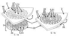
도 1a 및 도 1b는 돌출 부분들의 격자 및 평판을 포함하는 전달 장치 및 관통-공들의 격자를 포함하는 지지부의 대략적인 측면도이다.
도 2는 조리 장치, 상대적인 운동을 구동시키기 위한 시스템 및 전달 장치를 포함하는 조리 오븐의 대략적인 정면도이다.
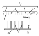
도 3는 시스템의 낮은 위치의 대략적인 프로파일 도면이다.
도 4는 시스템의 높은 위치의 대략적인 프로파일 도면이다.
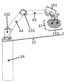
도 5는 처리 요소의 대략적인 측면도이다.
도 6은 조리 지지부 및 포크의 대략적인 경사도이다.
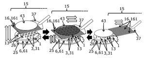
도 7은 처리 장치의 일 단에 위치되는 조리 지지부, 전달 장치 및 포크의 대략적인 경사도이다.
도 8은 상호대체가능한 안내 장치를 포함하는 조리 지지부의 대략적인 경사도이다.
도 9는 조리 지지부의 대략적인 상면도이다.
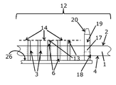
도 10은 상대적인 운동을 구동시키기 위한 시스템의 하부-부분의 대략적인 경사도이다.
도 11은 조리 장치의 대략적인 경사도이다. Other features and advantages of the present invention will become apparent by reading the following detailed description of implementations and embodiments which are given by way of non-
Figures 1a and 1b are schematic side views of a support comprising a grid of through-holes and a transfer device comprising a grid and a plate of protruding portions.
2 is a schematic front view of a cooking oven including a cooking device, a system for driving relative movement, and a delivery device.
Figure 3 is a schematic profile view of the lower position of the system.
Figure 4 is a schematic profile view of the high position of the system.
Figure 5 is a schematic side view of the processing element.
6 is an approximate slope of the cooking support and the fork.
7 is an approximate slope of the cooking support, the delivery device and the fork located at one end of the treatment device.
8 is an approximate slope of the cooking support including interchangeable guiding devices.
9 is a schematic top view of the cooking support.
10 is an approximate slope of the lower portion of the system for driving relative motion.
11 is an approximate slope of the cooking apparatus.
이하에서 설명될 실시예들은 한정하는 것은 아니기 때문에; 이 특징들의 선택이 종래 기술의 상태에 대하여 본 발명을 구별하거나 또는 기술적인 장점을 부여하기에 충분하다면, 설명되는 특징들의 선택만을 포함하는 본 발명의 변형들은 특히, 설명되는 다른 특징들과 분리되어, (이 선택이 다른 특징들을 포함하는 문장 안에서 분리되더라도), 예측될 수 있다. 이 선택은 적어도 하나의, 바람직하게 기능적인, 구조적인 상세사항들 없는, 또는 이 부분만으로도 종래 기술의 상태에 대하여 본 발명을 구별하거나 또는 기술적인 장점을 부여하기에 충분하다면 구조적인 상세사항들의 일 부분만을 가지는, 특징을 포함한다. The embodiments described below are not intended to be limiting; Variations of the present invention that include only the selection of features to be described, particularly if the selection of these features is sufficient to distinguish the present invention from the state of the art or to provide technical advantages, , (Even if this choice is separated in sentences containing other features). This selection may be made at least one, preferably functional, without structural details, or if this portion alone is sufficient to distinguish the invention from the state of the art or to give technical advantages, Quot; portion ".
도 1a 및 도 1b에 있어서, 지지부(1)는 요리 준비(43)(미도시)를 수령하기 위해 배치되는 상부 표면(2), 상부 표면(2)과 하부 표면(4) 사이에서 연장되는 관통-공들(3)의 격자(31)를 포함하는 것을 볼 수 있다. 관통-공들(3)은 바람직하게 그 지름이 1과 50 mm 사이에, 바람직하게 2와 20 mm 사이에, 더 바람직하게는 3과 10 mm 사이에 포함되는 원통형 형태를 가질 수 있고; 이들은 이 실시예에 따르면 8 mm의 지름을 가진다. 지지부(1)의 두께는 1 과 500 mm 사이에, 바람직하게는 10 과 100 mm 사이에, 보다 바람직하게는 15 와 50 mm 사이에 포함되고; 이것은 이 실시예에 따르면 20 mm이다. 1A and 1B, the
전달 장치(5)는 평판(25) 및 이 평판(25)에 수직하는 방향으로 상부 표면(26)으로부터 연장되는 돌출 부분들(6)의 격자(61)를 포함하는 것을 볼 수 있다. 돌출 부분들(6)의 하부-격자들 또한 서로 다른 지름들을 가지는 동심원들(28) 및 평행한 행들(27)로 구성되는 패턴들을 형성하는 것에 유의해야 한다. 돌출 부분들(6)의 형태 및 기하구조는 관통-공들(3)의 형태 및 기하구조에 적용되고, 돌출 부분들(6) 및 관통-공들(3)은 이 실시예에 따른 원통형 기하구조를 가진다. 돌출 부분들(6)의 하부-격자들은 또한 지지부(1) 상에, 서로 다른 지름들을 가지는 동심원들(47) 및 평행한 행들(46)로 구성되는 패턴들을 형성하는 것에 유의해야 한다. 행들(27)을 형성하는 돌출 부분들(6)은 행들(46)을 형성하는 관통-공들(3)에 상보적이고 또한 이에 삽입될 수 있다. 원들을 형성하는 돌출 부분들(6)은 원들(47)을 형성하는 관통-공들(3)에 상보적이고 또한 이에 삽입될 수 있다. 이 실시예에 따르면, 돌출 부분들(6)은 원통형 형태를 가지는 막대들(6)이다. 막대들(6)의 지름은 관통-공들(3)의 지름보다 0.5 mm 만큼 더 적고, 바람직하게는 1 mm 만큼 더 적고, 보다 바람직하게는 2 mm 만큼 더 적고; 이것은 이 실시예에 따르면 3 mm 만틈 더 적다. 막대들(6)의 지름은 이 실시예에 따르면 5 mm이다. 2 개의 인접하는 막대들(6)의 2 개의 대향하는 벽들 사이의 거리는 6 과 40 mm 사이에 포함되고; 이것은 이 실시예에 따르면 15 mm이다. 2 개의 막대들(6) 사이의 거리는 지지부(1) 상에 놓일 요리 준비(43)(미도시)에 적용된다. 딱딱한 준비들의 경우에 있어서, 막대들(6)은 딱딱하지 않은 준비들의 경우보다 더 큰 거리 만큼 이격되어 있을 수 있다. It can be seen that the
막대들(6)의 길이는 지지부(1)의 두께에 적용된다. 막대들(6)의 길이는 이에 대하여 막대들(6)이 돌출되는 지지부(1)의 상부 표면(2)과 돌출 막대들의 끝단(13) 사이의 거리는 1-100 mm 사이에, 바람직하게 5-50 mm 사이에, 보다 바람직하게는 10-30 mm 사이에 포함되고; 이것은 이 실시예에 따르면 15 mm이다. The length of the rods (6) is applied to the thickness of the support (1). The length of the
도 2에 있어서, 조리 장치(38)는 지지부(1), 중심 축(39), 회전으로 구동시키기 위한 장치(34), 교차 부재들(40)(미도시), 정지단들(41), 고정 바들(holding bars, 32), 고정 바들((32)을 고정시키기 위한 칼라(collar, 33)를 포함하는 것을 볼 수 있다. 6 개의 지지부들(1)이 도 2에 도시되어 있다. 회전으로 구동시키기 위한 장치(34)는 바람직하게 오븐(53)의 조리 엔클로저(cooking enclosure, 54) 외부에 위치된다. 알루미늄으로 만들어지는 열 싱크(heat sink)는 이 장치(34)의 근처의 온도를 효율적으로 감소시키기 위해 중심 축(39)과 회전으로 구동시키기 위한 장치(34) 사이에 설치될 수 있다. 고정 바들(32)은 고정 바들(32)을 고정하기 위해 칼라(33)에 일 단이 고정되고, 타 단은 교차 부재(40)에 고정된다. 이 고정 바들(32)은 교차 부재(40)에 고정되는 고정 바(32)의 끝 단과 고정 칼라(33) 사이의 거리를 조정하는 것을 가능하게 해주는 중간 요소(미도시)에 의해 분리되는 2 개의 부분들(미도시)로 구성된다. 이 조정은, 바람직하게 차가울 때 수행되는데, 이것은 교차 부재들(40)과 중심 축(39) 사이의, 이로써 지지부들(1)과 중심 축(39) 사이의 각을 설정하는 것을 가능하게 해준다. 고정 바들(32)은 2와 20 mm 사이에, 바람직하게 3 과 15 mm 사이에, 보다 바람직하게 4와 10 mm 사이에 포함되는 지름을 가지고; 이것들은 이 실시예에 따르면 6 mm의 지름을 가진다. 2, the
전달 장치(5)는 또한 평판(25)에 수직한 방향으로 이 평판(25)으로부터 연장되는 막대들(6)의 격자(61), 및 2 개의 안내 돌출 부분들(19)(이하에서 설명될)을 포함하는 것을 볼 수 있다. The
상대적인 운동을 구동시키기 위한 시스템은 또한 2 개의 고정 요소들(48)을 포함하고 또한 2 개의 하부-부분들로 구성되는 것을 볼 수 있는데, 고정 요소들(48) 각각은 상대적인 운동을 구동시키기 위한 시스템의 2 개의 하부-부분들 중 하나에 고정된다. 상대적인 운동을 구동시키기 위한 시스템은 또한 기어링 장치(91, 92, 93), 엑츄에이터(8), 안내 축(7), 롤링-요소 베어링(36) 및 이동가능한 요소(35)를 포함한다. 하부-부분들 각각은 조리 오븐(53)의 각각의 측면 상에 위치되어 더 나은 안정성, 더 나은 정확도, 더 나은 수명을 상대적인 운동을 구동시키기 위한 시스템에 제공하고 또한 오븐 아래에 필요한 공간을 감소시킨다. 상대적인 운동을 구동시키기 위한 시스템은 오븐(53) 외부에 위치되어 시스템의 요소들이 고온에 노출되는 것을 막게 된다. 이 실시예에 따르면, 상대적인 운동을 구동시키기 위한 전체 시스템은 병진 운동으로 수직으로, 즉 중심 축(39)에 평행한 방향으로, 고정 요소들(48)에 대하여 이로써 오븐(53)에 대하여, 움직인다. 이 실시예에 따르면, 상대적인 운동을 구동시키기 위한 시스템은 전달 장치(5)를 이동가능한 요소(35)를 거쳐 병진 운동으로, 구동시키기 위해 배치된다. It should be noted that the system for driving relative motion also includes two fixed
이 실시예에 따르면, 회전으로 구동시키기 위한 장치(34)는 중심 축(39) 주위에서 회전으로 구동될 수 있지만 어떠한 다른 방향으로 병진 운동으로 움직일 수는 없다. 회전으로 구동시키기 위한 장치(34)는 회전 운동 동안, 전달 장치(5) 위의 지지부들(1) 각각을 변위시키는 것이 가능하여, 이 전달 장치(5)의 병진 운동 동안, 돌출 부분들(6)의 격자(61)의 적어도 일 부분은 관통-공들(3)의 격자(31)의 적어도 일 부분에 삽입될 수 있다. According to this embodiment, the
도 3 및 도 4에 대략적으로 도시된 프로파일 도면들에 있어서, 시스템의 낮은 위치(11) 및 높은 위치(12)가 각각 도시되어 있고, 여기서 상부 표면(2) 및 하부 표면(4), 이 하부 표면(4)의 일 측면 상에 챔퍼(18)를 포함하는 안내 관통-공(17), 관통-공들(3)을 포함하는 지지부(1); 상부 표면(26)을 가지는 평판(25), 그 일 단에 챔퍼(20)를 가지는 안내 돌출 부분(19) 및 돌출 부분들(6)을 포함하는 전달 장치를 볼 수 있다. 안내 관통-공(17) 및 안내 돌출 부분(19)은 안내 장치를 형성한다. 지지부(1)의 하부 표면(4)의 일 측 상의 안내 관통-공(17)의 구멍은 바람직하게 그 형태가 장방형이다. 3 and 4, there is shown a
시스템의 낮은 위치(11)에 있어서, 지지부(1)의 상부 표면(2)에 대하여 돌출 부분(6, 19)은 돌출되지 않는다. 제안된 실시예에 있어서, 시스템이 낮은 위치(11)에 있을 때, 돌출 부분(6, 19)은 관통-공(3, 18)에 삽입되지 않는다. In the
시스템의 높은 위치(12)에 있어서, 돌출 부분들(6, 19)의 일 단(13)은 지지부(1)의 상부 표면(2)에 대하여 돌출한다. 이 경우에 있어서, 지지부(1)의 상부 표면(2)에 대하여 돌출되는 돌출 부분들(6, 19)의 끝단들(13)은 함께 지지부(1)의 상부 표면(2)에 대하여 상승된 표면(14)을 형성한다. 이로써 형성된 상승된 표면(14)은 요리 준비(43)를 수령할 수 있다. 이로써 형성된 상승된 표면(14)은 바람직하게 지지부(1)의 상부 표면(2)에 평행하다. One end (13) of the projecting portions (6, 19) protrudes from the upper surface (2) of the support (1) in the high position (12) In this case, the ends 13 of the projecting
도 5는 처리 암(15)의 운동을 구동시키기 위해 배치되는 베이스(24)의 일 단에 연결되고 장방형 요소들(16)의 격자(161)를 포함하는 포크(37)에 타 단이 연결되는 처리 암(handling arm, 15)의 대략적인 프로파일 도면이다. 이 실시예에 따르면 장방형 요소들(16)은 격자(161)를 형성하는 갈래들(16)이다. 포크(37)에 암(16)을 연결하는 관절(101)은 서로 다른 방향들로 갈래들(16)의 격자(161)가 방향지어지는 것을 가능하게 해준다. 다른 관절(102)은 베이스(24)에 암(15)을 연결하고 또한 서로 다른 방향들로 암(15)이 방향지어지는 것을 가능하게 해준다. 마지막 관절(103)은 처리 암(15)의 첫번째 부분(44)과 끝 부분(45) 사이에 위치된다.관절들(101, 102, 103)은 어떠한 평면에든 갈래들(16)의 격자(161)를 위치시키는 것을 가능하게 해준다. Figure 5 shows an alternative embodiment of the invention in which the other end is connected to a
도 6은 지지부(1)의 상부 표면(2)의 대략적인 경사도이고, 갈래들(16)을 포함하는 포크(37)는 지지부(1)의 상부 표면(2)에 대하여 돌출되는 막대들(6)에 의해 구성되는 돌출 부분들(6)의 끝단들(13)과 상호관통하는 격자(161)를 형성한다. 포크(37)의 2 개의 연속하는 갈래들(16)의 2 개의 대향하는 벽들을 분리하는 간격은 이 2 개의 갈래들(16) 사이에 삽입될 막대(6)의 지름에 대하여 1 mm, 바람직하게는 2 mm, 보다 바람직하게는 4 mm 더 크다. 처리 암(미도시)은, 그 일 단에 포크(37)가 위치되는데, 이것은 갈래들의 격자(161) 및 지지부(1)의 상부 표면(2)과 돌출 막대들(6)의 끝단들(13) 사이에 포함되는 막대들(6)의 일부가 암(15) 및/또는 포크(37)의 운동 동안 Figure 6 is an approximate slope of the
- 지지부(1)의 상부 표면(2)에 수직하는 방향으로, 또는In a direction perpendicular to the
- 지지부(1)의 삳부 표면(2)에 평행한 방향으로, 또는- in a direction parallel to the flank surface (2) of the support (1), or
- 지지부(1)의 상부 표면(2)에 평행하는 성분 및 수직하는 성분을 가지는 방향으로, 상호관통하도록 배치된다. 포크(37)의 갈래들의 격자(161)는 요리 준비(43)를 수령할 수 있는 표면을 형성하기 위해 배치된다. In such a direction as to have a component parallel to the
도 7은 관통-공들(3)의 격자(31)를 포함하는 지지부(1)의 상부 표면(2); 평판(25)의 상부 표면(26)(미도시)으로부터 연장되는 막대들(6)의 격자(61)를 포함하는 전달 장치의 경사도를 대략적으로 보여주는데, 이 시스템은 높은 위치(12)에 위치되고, 포크(37)는 갈래들(16)의 격자(161)을 포함한다. 7 shows the
포크(37)로부터 지지부(1)의 상부 표면(2)으로의 요리 준비(43)의 전달은 3 개의 단계들로 나눠질 수 있다. The transfer of the
제1 단계는 요리 준비(43)를 포크(37)의 갈래들(16)의 격자(161)에 의해 형성되는 표면으로부터 지지부(1)의 상부 표면(2)에 대하여 돌출되는 막대들(6)의 격자(61)의 끝단들(13)에 의해 형성되는 상승된 표면(14)(미도시)으로 전달하는 단계로 구성된다. 이 전달은 이 시스템이 초기에 높은 위치(12) 또는 낮은 위치(11)에 있을 때 수행될 수 있다. 이 시스템이 초기에 낮은 위치에 있을 때, 이 제1 단계는 The first step is to remove the
- 지지부(1)의 상부 표면(2)과 지지부(1)의 상부 표면(2)에 대하여 돌출되는 막대들(6)의 격자(61)의 끝단들(13)에 의해 형성되는 상승된 표면(14) 사이에 위치되는 평면에 포크(37)의 갈래들(16)의 격자(161)를 위치시키고, 이어서 이 시스템이 낮은 위치(11)에서 높은 위치(12)로 지나가도록, 지지부(1)를 향하여 또한 수직하는 또는 평행하는 방향으로 또는 지지부(1)의 상부 표면(2)에 평행한 성분 및 수직한 성분을 가지는 방향으로 암(15)의 운동(미도시) 동안 수행될 수 있다. 이 시스템이 낮은 위치(11)에서 높은 위치(12)로 지나갈 때, 막대들(6)의 끝단들(13)은An elevated surface formed by the
- 지지부(1)의 상부 표면(2)에 대하여 돌출되고, 그후- project against the upper surface (2) of the support part (1), thereafter
- 포크(37)의 갈래들(16)과 상호관통하고, - mutually penetrating with the
- 갈래들(16)의 격자(161)에 의해 형성되는 표면으로부터 상승된 표면(14)으로 요리 준비(43)를 전달하기 위해 요리 준비(43)의 하부 표면과 접촉하게 되고, Contacting the lower surface of the
- 상승된 표면(14)을 향해 갈래들(16)의 격자(161)에 의해 형성되는 표면에 대하여 요리 준비(43)가 승강된다. The
이 시스템이 초기에 높은 위치(12)에 있을 때, 이 제1 단계(미도시)는 When the system is initially in the
- 포크(37)의 갈래들(16)의 격자(161)에 의해 형성되는 표면에서 지지부(1)의 상부 표면(2)에 대하여 돌출되는 막대들(6)의 격자(61)의 끝단들(13)에 의해 형성되는 상승된 표면(14)으로 요리 준비(43)를 전달하도록, 지지부(1)를 향해 그리고 수직하는 방향으로 또는 지지부(1)의 상부 표면(2)에 평행한 성분 및 수직한 성분을 가지는 방향으로 암(15)의 운동 동안 수행될 수 있다. 이 운동 동안, 포크(37)의 갈래들(16)은 돌출 막대들(6)의 끝단들(13)과 상호관통하고 그후 지지부(1)의 상부 표면(2)과 지지부(1)의 상부 표면(2)에 대하여 돌출되는 막대들(6)의 끝단들(13)에 의해 형성되는 상승된 표면(14) 사이에 위치되는 평면 내에 있게 된다. The ends of the grids 61 of the
제2 단계는 지지부의 상부 표면(2)에 평행한 및/또는 포크(37)의 갈래들(16)에 평행한 방향으로 처리 암(15)의 운동 동안 지지부(1)의 상부 표면(2)에 대하여 돌출되는 막대들(6)의 끝단들(13)에 의해 형성되는 격자(61)로부터 포크(37)의 갈래들(16)의 격자(161)를 인출하는 단계를 포함한다.The second stage is the
제3 단계는 지지부(1)의 상부 표면(2)을 향하여 돌출되는 막대들(6)의 끝단들(13)에 의해 형성되는 상승된 표면(14)으로부터 요리 준비(43)를 전달하기 위해 이 시스템을 높은 위치(12)에서 낮은 위치(11)로 가져오는 단계를 포함한다. The third step is to transfer the
지지부(1)의 상부 표면(2)에서 포크(37)의 갈래들(16)의 격자(161)에 의해 형성되는 표면으로 요리 준비(43)의 전달은 3 개의 단계들로 나눠질 수 있다. The delivery of the
제1 단계는 지지부(1)의 상부 표면(2)에서 지지부(1)의 상부 표면(2)에 대하여 돌출되는 막대들(6)의 격자(61)의 끝단들(13)에 의해 형성되는 상승된 표면(14)으로 요리 준비(43)를 전달하도록 이 시스템을 낮은 위치(11)에서 높은 위치(12)로 가져오는 단계를 포함한다. The first step is a step of forming a
제2 단계는 지지부(1)의 상부 표면(2)에 평행한 방향으로 암(15)의 운동 동안 지지부(1)의 상부 표면(2)에 대하여 돌출되는 막대들(6)의 끝단들(13)에 의해 형성되는 격자(61)로 포크(37)의 갈래들(16)의 격자(161)를 삽입하는 단계를 포함한다. 포크(37)의 갈래들(16)의 격자(161)는 그후 지지부(1)의 상부 표면(2)과 지지부(1)의 상부 표면(2)에 대하여 돌출되는 막대들(6)의 격자(61)의 끝단들(13)에 의해 형성되는 상승된 표면(14) 사이에 위치되는 평면 내에 있게 된다. The second stage comprises the
제3 단계는 The third step is
- 지지부(1)의 상부 표면(2)에 대하여 평행 성분 및 수직 성분을 가지는 방향으로 암(15)의 운동 동안, 또는 - during the movement of the arm (15) in a direction having a parallel component and a vertical component relative to the upper surface (2) of the support part (1), or
- 높은 위치(12)에서 낮은 위치(11)로 이 시스템의 통과 동안: - During the passage of this system from a high position (12) to a low position (11):
요리 준비(43)를 지지부(1)의 상부 표면(2)에 대하여 돌출되는 막대들(6)의 격자(61)의 끝단들(13)에 의해 형성되는 상승된 표면(14)으로부터 포크(37)의 갈래들(16)의 격자(161)에 의해 형성되는 표면을 향해 전달하는 단계를 포함한다. The
요리 준비(43)의 지지부(1)의 상부 표면(2)에서 지지부(1)의 상부 표면(2)에 대하여 돌출되는 막대들(6)의 격자(61)의 끝단들(13)에 의해 형성되는 상승된 표면(14)으로의 이동 단계 동안, 운동을 구동시키기 위한 시스템에 의해 가해지는 최대 힘은 1000 뉴튼(N), 바람직하게 500 N, 보다 바람직하게는 200 N이고; 이 실시예에 따르면 이것은 150 N이다. Is formed by the
도 8은 이 실시예에 따라 관통-공들(3)의 격자(31)의 일 부분을 형성하지 않는 관통-공(21) 및 관통-공들(3)의 격자(31)를 포함하는 지지부(1)의 상부 표면(2)의 대략적인 경사도이다. 링(22)은 또한, 이 실시예에 따라, 지지부(1)의 상부 표면(2)의 일 측 상에 삽입되기 위해 배치되는 것을 볼 수 있다. 링(22)은 또한 그 면들(231, 232)이 전달 장치(5)의 돌출 부분들(6)이 삽입되거나 또는 삽입되고자 하는 지지부(1)의 하부 표면(4)의 일 측 상에 위치되는 링(22)의 구멍으로부터 연장되어 있는, 챔퍼(23)를 가진다. 링(22)은, 지지부(1)의 하부 표면(4)의 일 측 상에, 장방형의 형태인 구멍으로 존재한다. 챔퍼(23)의 절단 모서리 각은 5 와 45° 사이, 바람직하게 8 과 40°사이, 보다 바람직하게 10 과 30° 사이에 포함될 수 있고; 이 실시예에 따른 절단 모서리 각은 15°이다. Figure 8 shows a support 1 (1) comprising a grid 31 of through-
도 9에 대략적으로 도시된 지지부(1)의 상면도는 관통-공들(3)의 격자(31) 및 이 실시예에 따르면 격자(31)의 일 부분을 형성하지 않는 2 개의 안내 관통-공들(17)을 보여준다. 관통-공들(3)의 격자(31)의 특정한 배치는, 이 실시예에 따르면, 행들(46), 원들(47), 정사각형들(51), 사각형들(52)과 같은, 패턴들을 가지는 관통-공들의 하부-격자들을 포함한다. 관통-공들(3)의 하부-격자들은, 행들(27) 및 원들(28)의 패턴들(미도시)을 형성하는 막대들(6)의 하부-격자들(미도시)에 각각 상보적인 행들(46) 및 원들(47)의 패턴들에 의해 형성되는 것을 볼 수 있다. 행들(46)의 패턴들이 연장되는 2 개의 방향들 및 서로 다른 직경들의 동심원들(47)의2 개의 패턴들이 도시되어 있다. The top view of the
평면(30)의 x 방향으로, 15 개의 행들(46)이 있다. 이 행들(46)은 포크(37)의 16 개의 갈래들(16)과 협력하기 위해 배치되고, 이 갈래들의 14 개는 2 개의 연속적인 행들(46) 사이에 삽입되기 위해 배치되고 2 개의 추가적인 갈래들은 갈래들(16)의 격자(161)의 각각의 모서리에 위치된다. 게다가, 160, 240 및 300 mm의 직경들을 가지는 3 개의 동심원들(28)이 있다. 예를 들어, 직경 240 mm의 원(28)을 구성하는 관통-공들(3)은 240 mm 주변의 직경을 가지는 요리 준비(43)를 수령하기 위해 채택된 하부-격자를 형성한다. 직경 160 mm의 원을 형성하는 관통-공들은 160 mm 주변의 직경을 가지는 요리 준비들(43)을 수령하기 위해 채택된 하부-격자를 형성하고; 이 관통-공들의 하부-격자에 속하는 하부-격자는 직경 240 mm의 원을 형성한다. 이로써, 관통-공들(3)의 격자(31)는 원형 패턴들을 가지고 또한 160 과 300 mm 사이에 포함되는 직경들을 가지는, 바람직하게는 원형의 음식 준비들을 수령하기 위해 배치되는 2 개의 하부-격자들을 가진다. In the x direction of
2 개의 안내 관통-공들(17)이 관통-공들(3)의 격자(31) 외부에 위치되는 2 개의 대칭적으로 위치된 럭들(lugs) 상에 위치된다는 것에 유의해야 한다. 안내 관통-공들(17)은 관통-공들(3)의 격자(31)에 포함되지 않기 때문에, 오므라들 수 없는 안내 돌출 부분(19)을 포함하는 안내 장치를 이용하는 것은 가능하다. It should be noted that two guide through-
도 10은 상대적인 운동을 구동시키기 위한 시스템의 2 개의 하부-부분들 중 하나의 경사도이다. 상대적인 운동을 구동시키기 위한 시스템의 2 개의 하부-부분들 각각은, 하부-부분들 중 하나에만 실린더(8)가 연결되어 있는 것을 제외하고, 동일하게 배치되어 있는 동일 요소들을 포함한다. 도 10에 도시된 하부-부분은 기어링 장치(91, 92, 93)을 구동시키기 위해 배치되는 유압식 실린더(8)를 포함한다. 이 유압식 실린더(8)는 랙(rack, 92)을 레일(49)에서 병진 운동하게 구동시킨다. 이 랙(92)은 피니온(91)을 활성화시키고, 이 피니온은 랙(92)의 수평 병진 운동을 고정 요소(48)에 대한 상대적인 운동을 구동시키기 위한 전체 시스템의 수직 병진 운동으로 변환시키기 위해 구동 스크루(93)를 구동시킨다. 연결 요소(29)는 한편으로 롤링-요소 베어링(36)에, 다른 한편으로 피니온(91), 고정 요소(48)에 대한 운동을 구동시키기 위한 시스템의 수직 운동을 안내하기 위해 배치되는, 안내 축(7) 및 고정 요소에 고정되는, 구동 스크루(93)의 나사산에 상보적인 나사산을 가지는, 속이 빈 튜브(94)를 포함하는 조립체에 고정되는 것을 볼 수 있다. 기어링 장치(91, 92, 93)는 실린더(8)의 타격과 상대적인 운동을 구동시키기 위한 시스템의 타격 사이의 감소 비율을 조작하기 위해 배치된다. 안내 축(7)은 속이 빈 실린더(95) 내로 슬라이드하고, 이 속이 빈 실린더는 고정 요소(48)에 고정된다. 이 실시예에 따르면, 연결 요소(29)는, 이 실시예에 따르면 이동가능한 요소(35)를 구성하는, 2 개의 이동가능한 요소들(35)에 고정되는 타이(tie, 29)이다. 상대적인 운동을 구동시키기 위한 시스템의 2 개의 하부-부분들 각각의 안내 축(7)은 조정 장치(미도시)를 통해 고정 요소(48)에 각각 연결되고, 고정 요소들(48)에 대하여, 평면(30)에서, 그 전체로서 상대적인 운동을 구동시키기 위한 시스템의 위치를 설정하는 것을 가능하게 해준다. 이 실시예에 따르면, 이동가능한 요소들(35)은 전달 장치(5)에 연결되고, 조정 장치를 설정하는 것은 이 평면(30)에서 전달 장치(5)의 위치를 설정하는 것을 가능하게 해주고 이로써 관통-공들(3)의 격자(31)에 대하여 돌출 부분들(6)의 격자(61)의 정렬을 조정하는 것을 가능하게 해준다. Figure 10 is an oblique view of one of the two lower portions of the system for driving relative motion. Each of the two lower portions of the system for driving relative motion includes the same elements that are arranged identically, except that the
이동가능한 요소(35)에 연결되는, 롤링-요소 베어링(36)은, 이 이동가능한 요소(35)에 평면(30)에서의 기계적인 간격을 주는 것을 가능하게 해준다. 이동가능한 요소에 주어진 기계적인 간격은 1 과 20 mm 사이, 바람직하게 3 과 15 mm 사이, 보다 바람직하게 4 와 8 mm 사이에 포함되고; 이것은 이 실시예에 따르면 6 mm이다. The rolling-
랙(92)은, 제1 하부-부분으로 지칭되는, 도 10에 도시된 하부-부분으로부터 상대적인 운동을 구동시키기 위한 시스템의 제2 하부-부분(미도시)까지 연장된다. 도 10에 도시된 상대적인 운동을 구동시키기 위한 시스템의 제1 하부-부분은 랙(92)의 제1 단을 포함하고 또한 제2 하부-부분은 이 랙(92)의 제2 단을 포함한다. 상대적인 운동을 구동시키기 위한 시스템은 단지 하나의 실린더(8)만 가지기 때문에, 랙(92)의 병진 운동은 랙(92)에 의해 상대적인 운동을 구동시키기 위한 시스템의 제2 하부-부분(미도시)으로 전달된다. The
도 11은 조리 장치(38)의 대략적인 경사도이다. 이 조리 장치(38)는 특히 조리 오븐(53), 특히 피자 조리 오븐(53)의 엔클로저(54)에 결합되도록 채택된다. 고른 조리를 보장하고 그 품질을 개선시키기 위해, 이 오븐(53)에 사용되는 지지부(1)는 바람직하게 내화 석재일 것이다. 11 is an approximate slope of the
회전으로 구동시키기 위한 장치(34)(미도시)에 연결되는, 중심 축(39)은, 중심 축(39)에 수직하는 평면으로 연장되는 6 개의 교차 부재들(40)이, 제1 단에 의해, 그 위에 고정된 것을 볼 수 있다. 각각의 교차 부재(40)의 제2 단은 정지단(41)을 포함한다. 2 개의 인접하는 교차 부재들(40) 및 지지대에 고정시키기 위한 시스템(42) 또한 볼 수 있고; 지지대에 고정시키기 위한 각각의 시스템(42)은 중심 축(39)에 고정되고 이 2 개의 교차 부재들(40)과 접촉한다. A
이 도 11에 있어서, 조리 지지부(1)는 2 개의 인접하는 교차 부재들(40)을 지지하고, 이 지지부는 그 위에 안착하고 있는 인접하는 교차 부재들(40)의 끝단에 위치되는 2 개의 정지단에 대한 압력 하에서 고정된다. 이 조리 장치는 6 개의 조리 지지부들(1)을 포함할 수 있다. 지지부(1)는 중심 축(39)으로부터 연장되고 또한 이 인접하는 교차 부재들(40)을 연결하는 평면에 포함되는, 이 2 개의 인접하는 교차 부재들(40)로부터 등거리에 위치되는 중간을 포함하는 방향으로 압력을 가하는, 지지대에 고정시키기 위한 시스템(42)에 의한 압력 하에서 고정된다. 이 지지대에 고정시키기 위한 시스템(42)은 지지부(1) 및 금속 요소들, 그 중에서도, 교차 부재들(40)과 같은 금속 요소들의 열 팽창 계수들 사이의 차이로 인한 열 팽창 효과들에 의해 야기되는 불일치를 극복하는 것을 가능하게 해준다. 이 시스템은 주변 온도에서 조리 온도까지 갈 때 및 그 역에서도 조리 지지부들(1)의 +/- 0.5 mm의 위치 정확도를 유지하는 것을 가능하게 해준다. 11, the
도 11은 또한 지지부(1)의 상부 표면(2)과 하부 표면(4) 사이에서 연장되는 방향으로 지지부(1)의 상부 표면(2)의 위쪽에 위치되고 또한 중심 축(39)에 고정되는 고정 바들(32)을 고정하기 위한 칼라(33)를 보여준다. 이 고정 칼라(33)는 바람직하게 중심 축(39) 상에 면대면으로 고정되기 위해 배치되는 2 개의 반-원통형 링들을 포함한다. 고정 바들(32)은, 그 각각의 고정 바(32)가 고정 바들의 고정 칼라(33)와 교차 부재(40) 사이에서 연장되는 것을 볼 수 있다. 각각의 고정 바(32)는 고정 바(32)의 길이를 이로써 칼라(33)와 교차 부재(40) 사이의 거리를 또한 결과적으로 이 교차 부재(40)와 중심 축(39) 사이의 각을 조정하는 것을 가능하게 해주는 중간 요소가 그 사이에 위치되는(미도시), 2 개의 부분들(미도시)로 구성된다. 이러한 이유로, 2 개의 교차 부재들에 연결된 2 개의 고정 바들(32)을 조정함으로써, 이 조리 지지부(1)와 중심 축(39) 사이의 각을 조정하는 것이 가능하다. 이로써, 조리 지지부(1)와 중심 축(39) 사이의 각의 냉각 조정을 수행함으로써, 오븐(53)이 작동 중일 때, 오븐(53)이 작동 중일 때 조리 장치의 요소들의 열 팽창으로 인한 이 각의 변화들에 일조하는 것이 가능하다. 고정 브레이스들(50)은 그 위에 놓이는 2 개의 인접하는 교차 부재들(40)에 대한 지지대에 조리 지지부(1)를 고정하기 위해 배치된다. Figure 11 is also shown in Figure 2 which is positioned above the
물론, 본 발명은 이전에 설명된 예들에 한정되지 않고 수많은 조정들이 본 발명의 범위를 초과하지 않으면서 이 예들에 수행될 수 있다. Of course, the present invention is not limited to the examples described above, and numerous adjustments can be made to these examples without exceeding the scope of the present invention.
이로써, 이전에 언급된 실시예들의 변형들은 함께 결합될 수 있다: As such, variations of the previously mentioned embodiments can be combined together:
- 기어링 장치는 전달 장치(5)의 평판(25)에 결합될 수 있고 또한 평판(25)에 대하여 막대들(6)의 운동을 구동시키기 위해 배치되고, The gearing device can be coupled to the
- 낮은 위치(11)에 있을 때, 막대들(6)은 지지부(1)의 관통-공들(3)에 영구히 삽입되고 또한 지지부(1)의 상부 표면(2)과 동일한 높이에 있게 되고, When in the
- 구멍(21)은, 관통-공일 수 있거나 또는 아닐 수 있는데, 안내 장치에 있어서, 관통-공들(3)의 격자(31)의 일 부분을 형성할 수 있고, The
- 안내 관통-공(17)은 관통-공들(3)의 격자(31)의 일 부분을 형성할 수 있고, - the guiding through-hole (17) can form part of the grating (31) of the through-balls (3)
- 안내 돌출 부분(19)은 돌출 부분들(6)의 격자(61)의 일 부분을 형성할 수 있고, The
- 링(22)은 나사결합에 의해 지지부(1)에 삽입되기 위해 구멍(21)에 생성된 암나사산에 상보적인 숫나사산을 포함할 수 있고, The
- 하부-격자들의 패턴들은 요리 준비들(43)의 기하구조에 채택되고, The patterns of the sub-grids are employed in the geometry of the
- 조리 장치(38)의 요소들은 바람직하게 스틸 요소들, 보다 바람직하게는 스테인레스 스틸로 만들어지고, The elements of the
- 지지대에 고정시키기 위한 시스템(42)에 의해 가해지는 압력은, 바람직하게는 그 열 특성들에 대하여 당업자에게 알려진 물질로부터, 특히 니켈 및 크롬을 포함하는 합금으로부터 만들어지는, 스프링에 의해, 제공될 수 있고; 바람직하게 스프링은 Inconel®을 포함할 수 있고 The pressure exerted by the
- 돌출 부분들(6)은 바람직하게 스테인레스 스틸로부터 만들어질 수 있고,The protruding
- 갈래들(16)의 격자 또는 하부-격자들은 서로 다른 종류들, 서로 다른 기하구조들 및 서로 다른 크기들의 요리 준비들을 동시에 또는 연속적으로 수령하기 위해 채택될 수 있고, The lattice or sub-lattices of the
- 돌출 부분들(6)의 하부-격자들의 일 부분만이 지지부(1)의 상부 표면(2)에 대하여 돌출될 때, 이 하부-격자들은 수 개의 상승된 표면들(14)을 형성하기 위해 배치될 수 있고, 이 상승된 표면들(14) 중 하나의 기하구조는 다른 상승된 표면(14)의 기하구조 또는 수 개의 다른 상승된 표면들(14)의 기하구조들 또는 다른 모든 상승된 표면들(14)의 기하구조들과 다를 수 있고, When only a portion of the lower-gratings of the protruding
- 돌출 부분들(6)의 하부-격자들의 일 부분만이 지지부(1)의 상부 표면(2)에 대하여 돌출될 때, 지지부(1)의 상부 표면(2)과 돌출된 돌출 부분들(6)의 하부-격자들 중 하나에 의해 형성되는 상승된 표면(14) 사이의 거리는 지지부(1)의 상부 표면(2)과 돌출된 돌출 부분들(6)의 하부-격자들 중 다른 하나에 의해 형성되는 다른 상승된 표면(14) 사이의 거리와 다를 수 있고, The
- 돌출 부분들(6)의 하부-격자들의 일 부분만이 지지부(1)의 상부 표면(2)에 대하여 돌출될 때, 지지부(1)의 상부 표면(2)과 돌출된 돌출 부분들(6)의 하부-격자들 중 하나에 의해 형성되는 상승된 표면(14) 사이의 거리는 지지부(1)의 상부 표면(2)과 돌출된 돌출 부분들(6)의 하부-격자들 중 다른 수 개에 의해 형성되는 다른 수 개의 상승된 표면들(14) 사이의 거리(들)과 다를 수 있고, The
- 돌출 부분들(6)의 하부-격자들의 일 부분만이 지지부(1)의 상부 표면(2)에 대하여 돌출될 때, 지지부(1)의 상부 표면(2)과 돌출된 돌출 부분들(6)의 하부-격자들 중 하나에 의해 형성되는 상승된 표면(14) 사이의 거리는 지지부(1)의 상부 표면(2)과 돌출된 돌출 부분들(6)의 다른 하부-격자들 모두에 의해 형성되는 다른 상승된 모든 표면들(14) 사이의 거리(들)과 다를 수 있고, The
- 이동가능한 요소(35)는 전달 장치(5)에 또는 지지부(1)에 연결될 수 있고; 전달 장치(5)에 연결되지 않는 부분(5 또는 1)은 운동을 구동시키기 위한 시스템이 활성화될 때 바람직하게 움직이지 않고; 조정 장치를 설정하는 것은 평면(30) 내에 지지부(1)의 또는 전달 장치(5)의 위치를 설정하고 이로써 관통-공들(3)의 격자(31)에 대하여 돌출 부분들(6)의 격자(61)의 정렬을 조정하는 것을 가능하게 해주고, The
- 이동가능한 요소(35)는 전달 장치(5)에 또는 지지부(1)에 연결될 수 있고; 전달 장치(5)에 연결되지 않는 부분(5 또는 1)은 운동을 구동시키기 위한 시스템이 활성화될 때 바람직하게 움직이지 않고, The
- 안내 돌출 부분(19)은 자동으로 후퇴될 수 있고, The
- 안내 돌출 부분(19)은 그 변위 방향에 반대되는 방향으로 가해지는 힘을 만났을 때 후퇴될 수 있고; 후퇴를 야기시키는 힘의 값은 미리 결정될 수 있고, The
- 안내 돌출 부분(19)은 지지부(1)의 상부 표면(2)과 하부 표면(4)을 연결하는 방향에 평행한 방향으로 가해지는 힘을 만났을 때 후퇴될 수 있고, 후퇴를 야기시키는 힘의 값은 미리 결정될 수 있고, The
- 돌출 부분(6)은 자동으로 후퇴될 수 있고, The projecting
- 돌출 부분(6)은 그 변위 방향에 반대되는 방향으로 가해지는 힘을 만났을 때 후퇴될 수 있고; 후퇴를 야기시키는 힘의 값은 미리 결정될 수 있고, The projecting
- 돌출 부분(6)은 지지부(1)의 상부 표면(2)과 하부 표면(4)을 연결하는 방향에 평행한 방향으로 가해지는 힘을 만났을 때 후퇴될 수 있고, 후퇴를 야기시키는 힘의 값은 미리 결정될 수 있고, The projecting
- 지지부(1)의 상부 표면(2) 및/또는 하부 표면(4)은 평면이 아니고, 예를 들어 홈들 및/또는 거친 부분들 및/또는 채널들을 가지고, The
- 평판(25)의 상부 표면(26)은 평면이 아니고, 예를 들어 홈들 및/또는 거친 부분들 및/또는 채널들을 가진다. The
이에 더하여, 본 발명의 다양한 특징들, 형태들, 변형들 및 실시예들은, 양립불가하거나 또는 상호 배타적이지 않는 범위에서, 다양한 조합들로 함께 결합될 수 있다. In addition, various features, forms, modifications and embodiments of the present invention may be combined together in various combinations, to the extent that they are incompatible or mutually exclusive.
Claims (18)
- 지지부(1). 상기 지지부는
● 요리 준비(43)를 수령하기 위해 준비되는 상부 표면(2), 및
● 상기 상부 표면과 하부 표면(4) 사이에서 연장되는 복수의 관통 공들(3)을 포함하고,
- 복수의 돌출 부분들(6)을 포함하는 전달 장치(5),
- 상기 전달 장치의 적어도 일 부분에 대하여 상기 지지부의 상대적 운동(7,8,9,29,35,36,48,93)을 구동시키기 위한 시스템을 포함하고,
상기 시스템은 상기 상대적 운동을 구동시키기 위한 시스템이
● 돌출 부분이 상기 지지부의 상기 상부 표면에 대하여 돌출되지 않는, 낮은 위치(11),
● 상기 관통 공들을 통해, 상기 지지부의 상기 상부 표면에 대하여, 상기 적어도 하나의 돌출 부분의 일 단(13)이 돌출되어, 이로써 상기 요리 준비는 더 이상 상기 지지부의 상기 상부 표면 상에 남아 있지 않는, 더 높은 위치(12)에 상기 시스템이 위치되도록 배치되고
또한 상기 돌출 부분들 사이에 삽입되기 위해 배치되는 장방형 요소들(16)을 포함하는 처리 도구(37)를 포함하는 것을 특징으로 하는, 요리 준비들을 처리하기 위한 시스템. A system for processing cooking preparations,
- Support (1). The support
- a top surface (2) prepared for receiving the cooking preparation (43), and
- a plurality of through holes (3) extending between the upper surface and the lower surface (4)
- a transfer device (5) comprising a plurality of protruding parts (6)
- a system for driving relative movements (7, 8, 9, 29, 35, 36, 48, 93) of said support relative to at least a portion of said delivery device,
The system includes a system for driving the relative motion
Characterized in that the projecting portion does not project against the upper surface of the support,
- through said through holes, one end (13) of said at least one projecting part protrudes, with respect to said upper surface of said support, whereby said cooking preparation no longer remains on said upper surface of said support , The system is positioned to be located at a higher position (12)
Further comprising a processing tool (37) comprising rectangular elements (16) arranged to be inserted between said protruding portions.
- 상기 전달 장치(5)는 패턴으로 배치되는 돌출 부분들(61)의 격자를 포함하고,
- 상기 지지부(1)는 상기 돌출 부분들의 격자의 패턴에 상보적인 패턴으로 배치되는 관통 공들(31)의 격자를 포함하고;
상기 격자들은 상기 돌출 부분들의 격자가 상기 관통 공들의 격자로 삽입될 수 있도록 배치되는 것을 특징으로 하는, 요리 준비들을 처리하기 위한 시스템. The method according to claim 1,
- the delivery device (5) comprises a grid of protruding parts (61) arranged in a pattern,
- the support part (1) comprises a grid of through holes (31) arranged in a pattern complementary to the pattern of the gratings of the projecting parts;
Characterized in that the gratings are arranged such that a grating of the protruding portions can be inserted into the grating of the through holes.
- 상기 지지부(1)의 하부 표면(4)에 생성되는 적어도 하나의 관통-공(21),
- 상기 적어도 하나의 관통-공에 제거가능하게 삽입되기 위해 배치되는 적어도 하나의 링(22)을 포함하는 호환성 관통-공 안내 장치(21, 22)를 포함하는 것을 특징으로 하는, 요리 준비들을 처리하기 위한 시스템. 8. The method according to any one of claims 1 to 7,
- at least one through-hole (21) formed in the lower surface (4) of said support part (1)
(21, 22) comprising at least one ring (22) arranged to be removably inserted into said at least one through-hole, characterized in that it comprises a through- ≪ / RTI >
- 상기 지지부(1)의 상기 하부 표면(4)에 생성되는 적어도 하나의 블라인드 개구부,
- 상기 적어도 하나의 블라인드 개구부에 제거가능하게 삽입되기 위해 배치되는 적어도 하나의 링,
- 상기 적어도 하나의 블라인드 개구부에 삽입되기 위해 배치되고 또한 상기 다른 돌출 부분들(6)에 대하여 상대적 운동이 가능한 적어도 하나의 후퇴가능한 안내 돌출 부분을 포함하는 블라인드 호환성 안내 장치를 포함하는 것을 특징으로 하는, 요리 준비들을 처리하기 위한 시스템. 8. The method according to any one of claims 1 to 7,
- at least one blind opening formed in said lower surface (4) of said support (1)
At least one ring arranged for removable insertion in the at least one blind opening,
- at least one retractable guide projection arranged for insertion in said at least one blind opening and capable of relative movement with respect to said other projecting portions (6) , A system for processing cooking preparations.
- 적어도 하나의 고정 요소(48),
- 상기 적어도 하나의 고정 요소에 연결되는 적어도 하나의 기어링 장치(91,92,93),
- 상기 기어링 장치를 구동시키기 위해 배치되는 적어도 하나의 엑츄에이터(8)를 포함하고,
또한 상기 전달 장치(5) 또는 상기 지지부(1)의 고정 수단은
- 상기 전달 장치에 또는 상기 지지부에 고정되는 이동가능한 부분(35),
- 상기 기어링 장치에 고정되는 연결 요소(29),
- 한편으로는 상기 이동가능한 부분에 다른 한편으로는 상기 연결 요소에 연결되는 롤링-요소 베어링(36)을 포함하고, 상기 기어링 장치는 상기 적어도 하나의 고정 부분에 대하여 상대적 운동으로 상기 이동가능한 부분을 구동시키기 위해 배치되는 것을 특징으로 하는, 요리 준비들을 처리하기 위한 시스템. 13. The system according to any one of the preceding claims, wherein the system for driving the relative motion comprises:
- at least one stationary element (48),
- at least one gearing device (91, 92, 93) connected to said at least one stationary element,
- at least one actuator (8) arranged to drive said gearing device,
Further, the fixing device of the transfer device (5) or the support part (1)
- a movable part (35) which is fixed to said delivery device or to said support,
A coupling element (29) fixed to the gearing device,
- a rolling-element bearing (36) which on the one hand is connected to said movable part and on the other hand to said connecting element, said gearing device being movable relative to said at least one stationary part Wherein the system is arranged to drive the cooking utensils.
- 수 개의 조리 지지부(1),
- 회전으로 구동되기 위해 배치되는 중심 축(39),
- 상기 중심 축에 고정되는 교차 부재들(40),
- 정지단들(41),
- 지지대에 고정하기 위한 시스템(42)을 포함하는 조리 장치(38)를 포함하고; 조리 지지부(1)는 2 개의 인접하는 교차 부재들(40) 상의 지지대에 놓이도록 배치되고 또한 지지대에 고정하기 위한 시스템(42)은 상기 조리 지지부(1)에 일정한 압력을 가하여 하나 또는 그 이상의 정지단들(41)에 대한 압력 하에서 상기 조리 지지부를 고정하는 것을 특징으로 하는, 요리 준비들을 처리하기 위한 시스템. 17. The method according to any one of claims 1 to 16,
- several cooking supports (1),
- a central axis (39) arranged to be driven by rotation,
Intersecting members (40) fixed to the central axis,
- stopping stages (41),
- a cooking device (38) comprising a system (42) for fixing to a support; The cooking support 1 is arranged to rest on a support on two adjacent intersecting members 40 and the system 42 for fixing to the support rests one or more stops by applying a constant pressure to the cooking support 1, Characterized in that the cooking support is secured under pressure to the steps (41).
Applications Claiming Priority (5)
| Application Number | Priority Date | Filing Date | Title |
|---|---|---|---|
| FR1650844A FR3047150B1 (en) | 2016-02-03 | 2016-02-03 | DEVICE FOR FORMING A PULLEY LOWERED FROM A PATTERN BY PRESSING |
| FR1650844 | 2016-02-03 | ||
| FR1750806A FR3047148B1 (en) | 2016-02-03 | 2017-01-31 | HANDLING SYSTEM FOR CULINARY PREPARATIONS |
| FR1750806 | 2017-01-31 | ||
| PCT/EP2017/052225 WO2017134149A1 (en) | 2016-02-03 | 2017-02-02 | System for handling culinary preparations |
Publications (2)
| Publication Number | Publication Date |
|---|---|
| KR20180098686A true KR20180098686A (en) | 2018-09-04 |
| KR101968063B1 KR101968063B1 (en) | 2019-08-19 |
Family
ID=56263810
Family Applications (2)
| Application Number | Title | Priority Date | Filing Date |
|---|---|---|---|
| KR1020187024293A Active KR101968062B1 (en) | 2016-02-03 | 2017-02-02 | Apparatus for forming a sheet-like dough from a dough piece by pressing |
| KR1020187024349A Active KR101968063B1 (en) | 2016-02-03 | 2017-02-02 | System for Processing Cooking Formulations |
Family Applications Before (1)
| Application Number | Title | Priority Date | Filing Date |
|---|---|---|---|
| KR1020187024293A Active KR101968062B1 (en) | 2016-02-03 | 2017-02-02 | Apparatus for forming a sheet-like dough from a dough piece by pressing |
Country Status (12)
| Country | Link |
|---|---|
| US (2) | US10681916B2 (en) |
| EP (2) | EP3410859B1 (en) |
| KR (2) | KR101968062B1 (en) |
| CY (1) | CY1122595T1 (en) |
| DK (2) | DK3410860T3 (en) |
| ES (2) | ES2737306T3 (en) |
| FR (2) | FR3047150B1 (en) |
| HU (2) | HUE044518T2 (en) |
| PL (2) | PL3410859T3 (en) |
| PT (2) | PT3410859T (en) |
| TR (1) | TR201910362T4 (en) |
| WO (2) | WO2017134150A1 (en) |
Cited By (2)
| Publication number | Priority date | Publication date | Assignee | Title |
|---|---|---|---|---|
| KR101982597B1 (en) * | 2018-10-02 | 2019-05-27 | 강삼태 | Pizza manufacturing apparatus and manufacturing method |
| KR102737072B1 (en) * | 2024-04-30 | 2024-11-29 | 씨제이푸드빌 주식회사 | Automatic Dough Mixing Device Comprising Spatula Tool and Method for Preparing Castella Using Same |
Families Citing this family (23)
| Publication number | Priority date | Publication date | Assignee | Title |
|---|---|---|---|---|
| US9292889B2 (en) | 2013-06-18 | 2016-03-22 | Zume Pizza, Inc. | Systems and methods of preparing food products |
| DE102015005166B4 (en) | 2015-04-23 | 2019-01-10 | Eismann Innovations GmbH | Vehicle with a device for processing food |
| US11790403B2 (en) | 2017-06-20 | 2023-10-17 | Congruens Group, Llc | Vehicle with context sensitive information presentation |
| CN110892459A (en) | 2017-07-11 | 2020-03-17 | 祖美股份有限公司 | Multimodal delivery system and method using kiosks and autonomous delivery vehicles |
| US20190270398A1 (en) | 2017-07-14 | 2019-09-05 | Zume, Inc. | Vending-kiosk based systems and methods to vend and/or prepare items, for instance prepared foods |
| WO2019079345A1 (en) | 2017-10-18 | 2019-04-25 | Zume Pizza, Inc. | On-demand robotic food assembly equipment, and related systems and methods |
| CN107878093B (en) * | 2017-11-28 | 2019-04-05 | 安徽机电职业技术学院 | A kind of automatically controlled multi-angle product embossing device |
| USD900862S1 (en) | 2018-03-20 | 2020-11-03 | Zume Pizza, Inc. | Display screen with graphical user interface |
| WO2019232506A1 (en) | 2018-06-01 | 2019-12-05 | Zume, Inc. | Delivery vehicles for en route food product preparation |
| CN108669109B (en) * | 2018-07-22 | 2023-10-03 | 邵嘉阳 | Pancake machine |
| CN108669108B (en) * | 2018-07-22 | 2023-10-03 | 邵嘉阳 | Pancake machine |
| CN108634811B (en) * | 2018-07-22 | 2024-07-23 | 邵嘉阳 | Pancake machine |
| CN108577584B (en) * | 2018-07-22 | 2024-05-03 | 邵嘉阳 | Pancake machine |
| US11816624B2 (en) | 2018-11-27 | 2023-11-14 | Congruens Group, Llc | Delivery of food items by aerial or ground drones to and from delivery vehicles |
| KR102208465B1 (en) * | 2019-01-30 | 2021-01-27 | (주)바른푸드 | Dough forming apparatus for pizza |
| US11178879B2 (en) | 2020-03-12 | 2021-11-23 | James R. Kesler | Automated pizza-making system |
| FR3109264B1 (en) * | 2020-04-15 | 2024-10-18 | Ekim | Process for recovering a culinary preparation |
| US11433549B2 (en) | 2020-12-03 | 2022-09-06 | Wolfe Electric, Inc. | Pizza transfer tool |
| CN113951295A (en) * | 2021-02-08 | 2022-01-21 | 江门市米道科技有限公司 | Dough sheet pressing machine |
| US12347261B2 (en) * | 2021-05-26 | 2025-07-01 | Guangzhou Light Industry Elec Co., Ltd | Conveying device, pizza vending machine, and automatic pizza selling system |
| CN113796401A (en) * | 2021-08-28 | 2021-12-17 | 李纪淮 | Moon cake production system |
| CN115517386B (en) * | 2022-03-08 | 2023-09-08 | 威宁县一品鲜食品有限公司 | Pressing device for food processing and forming |
| FR3157069B1 (en) * | 2023-12-21 | 2025-11-21 | Flamm Top | Method for producing folded-edge pie crusts in a dough processing machine for producing folded-edge pie crusts and such a processing machine |
Citations (3)
| Publication number | Priority date | Publication date | Assignee | Title |
|---|---|---|---|---|
| EP1107199A2 (en) * | 1999-12-03 | 2001-06-13 | Top Vending Srl | Vending apparatus for dispensing hot pizzas |
| US20070178198A1 (en) * | 2006-01-30 | 2007-08-02 | Lichtenstein David M | Making pastry shells |
| EP2174549A1 (en) * | 2008-10-13 | 2010-04-14 | Iteca S.p.a. | Apparatus for forming disk-like elements of food dough |
Family Cites Families (18)
| Publication number | Priority date | Publication date | Assignee | Title |
|---|---|---|---|---|
| US2770182A (en) * | 1954-07-02 | 1956-11-13 | William B Lynch | Electric meat fryer |
| US3687688A (en) * | 1969-10-27 | 1972-08-29 | Rulon Floyd Stapley | Method of making potato products |
| US3736859A (en) * | 1971-06-10 | 1973-06-05 | A Carlson | Cooking iron |
| US4569815A (en) * | 1983-06-20 | 1986-02-11 | Rentz Robert I | Method and device for simultaneously propelling and forming impressions with a flowable material |
| US4715357A (en) * | 1985-11-26 | 1987-12-29 | Victor Sherman | Apparatus for cooking food |
| US5170696A (en) * | 1989-02-06 | 1992-12-15 | Reed Claude A | Food product and method and apparatus for preparing food products |
| US5070775A (en) * | 1991-01-09 | 1991-12-10 | Bottomline Management, Inc. | Removable cooking surface for the movable platen of a two-sided cooking device |
| US5934182A (en) * | 1996-06-06 | 1999-08-10 | Garland Commercial Industries, Inc. | Two-surfaced grill with computer controlled two stage upper platen positioning mechanism |
| AU763526B2 (en) | 1996-07-25 | 2003-07-24 | Bernardo Brini | Apparatus and method for making pizza |
| US5921170A (en) * | 1996-07-25 | 1999-07-13 | Puzant Khatchadourian | Apparatus for making and dispensing pizza |
| JP3463172B2 (en) * | 1997-04-18 | 2003-11-05 | アー フリッチュ ゲーエムベーハー ウント コンパニー コマンディト ゲゼルシャフト | Equipment for separating individual dough pieces from a continuous dough transport path |
| US6386854B1 (en) * | 2000-03-27 | 2002-05-14 | Tammy L Guss | Press for forming a compressible food item |
| EP1145635A1 (en) | 2000-04-04 | 2001-10-17 | Cabinplant International A/S | Method of and apparatus for applying and distributing a charge of a particulate material onto a top surface of a substrate, such as a pizza batter |
| US6398539B1 (en) * | 2000-08-15 | 2002-06-04 | Lawrence Equipment, Inc. | Pizza die with seal |
| CN103037697B (en) | 2010-02-26 | 2016-12-14 | 小凯撒企业股份有限公司 | Automatization's pizza component system |
| TW201236568A (en) | 2011-01-18 | 2012-09-16 | K & G Entpr Llc | Improved automated pizza preparation and vending system |
| FR2971122B1 (en) | 2011-02-04 | 2013-02-22 | Jean-Louis Hecht | AUTOMATIC FEEDER |
| US9210946B2 (en) * | 2012-10-15 | 2015-12-15 | Steven P. Hoffman | Potato piercing apparatus |
-
2016
- 2016-02-03 FR FR1650844A patent/FR3047150B1/en active Active
-
2017
- 2017-01-31 FR FR1750806A patent/FR3047148B1/en active Active
- 2017-02-02 US US16/074,741 patent/US10681916B2/en active Active
- 2017-02-02 PL PL17706695T patent/PL3410859T3/en unknown
- 2017-02-02 PL PL17706696T patent/PL3410860T3/en unknown
- 2017-02-02 KR KR1020187024293A patent/KR101968062B1/en active Active
- 2017-02-02 EP EP17706695.8A patent/EP3410859B1/en active Active
- 2017-02-02 EP EP17706696.6A patent/EP3410860B1/en active Active
- 2017-02-02 WO PCT/EP2017/052230 patent/WO2017134150A1/en not_active Ceased
- 2017-02-02 DK DK17706696.6T patent/DK3410860T3/en active
- 2017-02-02 PT PT17706695T patent/PT3410859T/en unknown
- 2017-02-02 PT PT17706696T patent/PT3410860T/en unknown
- 2017-02-02 KR KR1020187024349A patent/KR101968063B1/en active Active
- 2017-02-02 HU HUE17706695 patent/HUE044518T2/en unknown
- 2017-02-02 ES ES17706695T patent/ES2737306T3/en active Active
- 2017-02-02 US US16/074,999 patent/US10701943B2/en active Active
- 2017-02-02 ES ES17706696T patent/ES2734324T3/en active Active
- 2017-02-02 HU HUE17706696 patent/HUE044437T2/en unknown
- 2017-02-02 WO PCT/EP2017/052225 patent/WO2017134149A1/en not_active Ceased
- 2017-02-02 TR TR2019/10362T patent/TR201910362T4/en unknown
- 2017-02-02 DK DK17706695.8T patent/DK3410859T3/en active
-
2019
- 2019-07-03 CY CY20191100701T patent/CY1122595T1/en unknown
Patent Citations (3)
| Publication number | Priority date | Publication date | Assignee | Title |
|---|---|---|---|---|
| EP1107199A2 (en) * | 1999-12-03 | 2001-06-13 | Top Vending Srl | Vending apparatus for dispensing hot pizzas |
| US20070178198A1 (en) * | 2006-01-30 | 2007-08-02 | Lichtenstein David M | Making pastry shells |
| EP2174549A1 (en) * | 2008-10-13 | 2010-04-14 | Iteca S.p.a. | Apparatus for forming disk-like elements of food dough |
Cited By (2)
| Publication number | Priority date | Publication date | Assignee | Title |
|---|---|---|---|---|
| KR101982597B1 (en) * | 2018-10-02 | 2019-05-27 | 강삼태 | Pizza manufacturing apparatus and manufacturing method |
| KR102737072B1 (en) * | 2024-04-30 | 2024-11-29 | 씨제이푸드빌 주식회사 | Automatic Dough Mixing Device Comprising Spatula Tool and Method for Preparing Castella Using Same |
Also Published As
| Publication number | Publication date |
|---|---|
| KR101968062B1 (en) | 2019-04-10 |
| PL3410859T3 (en) | 2019-09-30 |
| DK3410859T3 (en) | 2019-08-05 |
| FR3047150B1 (en) | 2018-02-16 |
| KR101968063B1 (en) | 2019-08-19 |
| FR3047150A1 (en) | 2017-08-04 |
| EP3410859A1 (en) | 2018-12-12 |
| ES2734324T3 (en) | 2019-12-05 |
| HUE044518T2 (en) | 2019-10-28 |
| EP3410860A1 (en) | 2018-12-12 |
| FR3047148B1 (en) | 2018-02-16 |
| CY1122595T1 (en) | 2021-01-27 |
| US10701943B2 (en) | 2020-07-07 |
| ES2737306T3 (en) | 2020-01-13 |
| DK3410860T3 (en) | 2019-08-05 |
| PT3410860T (en) | 2019-08-07 |
| US20190037860A1 (en) | 2019-02-07 |
| PT3410859T (en) | 2019-08-06 |
| EP3410860B1 (en) | 2019-05-01 |
| KR20180100243A (en) | 2018-09-07 |
| US20190037859A1 (en) | 2019-02-07 |
| HUE044437T2 (en) | 2019-10-28 |
| US10681916B2 (en) | 2020-06-16 |
| WO2017134150A1 (en) | 2017-08-10 |
| EP3410859B1 (en) | 2019-05-01 |
| TR201910362T4 (en) | 2019-08-21 |
| FR3047148A1 (en) | 2017-08-04 |
| PL3410860T3 (en) | 2019-10-31 |
| WO2017134149A1 (en) | 2017-08-10 |
Similar Documents
| Publication | Publication Date | Title |
|---|---|---|
| KR20180098686A (en) | A system for processing cooking preparations | |
| CN103549877B (en) | Sandwich maker and method of making sandwiches using same | |
| JP5850504B2 (en) | Apparatus for baking dough-based foods, nets and methods for baking such products | |
| US6287619B1 (en) | Implements for use in preparing sliced food products | |
| EP2958469A1 (en) | Adjustable pitch cooking grate | |
| US20120244270A1 (en) | Apparatus and methods for reheating wedge shaped food products, such as one or more pizza slices | |
| CZ286403B6 (en) | Apparatus for baking pies | |
| US5713264A (en) | Method and system for automatically grilling food products | |
| HK40001902B (en) | System for handling culinary preparations | |
| HK40001902A (en) | System for handling culinary preparations | |
| EP3803214B1 (en) | Cooker appliance comprising baking stone | |
| EP2114221B1 (en) | Cooking device for barbeque | |
| JP7656075B2 (en) | Apparatus and method for transporting food products | |
| WO2024154127A1 (en) | Cooking apparatus for robotic chef with integrated drive system for multiple cooking spaces | |
| HK40001903A (en) | Device for forming a sheeted dough from a dough piece by pressing | |
| JP2025067438A (en) | Food Transfer Device | |
| EP3820338B1 (en) | Food imprinting system | |
| JP2023111278A (en) | Frozen baked food manufacturing apparatus and frozen baked food manufacturing method | |
| HK1226253A1 (en) | Sandwich making appliance and method of making a sandwich with the same | |
| JP6228247B2 (en) | Egg processing frame and method for producing processed egg product using the same | |
| DE94876C (en) | ||
| JP2016106529A (en) | Cookware | |
| GB2561850A (en) | Feature for an oven tray | |
| HK1202787B (en) | Sandwich making appliance and method of making a sandwich with the same | |
| HK1188698B (en) | Sandwich making appliance and method of making a sandwich with the same |
Legal Events
| Date | Code | Title | Description |
|---|---|---|---|
| A201 | Request for examination | ||
| A302 | Request for accelerated examination | ||
| PA0105 | International application |
Patent event date: 20180823 Patent event code: PA01051R01D Comment text: International Patent Application |
|
| PA0201 | Request for examination | ||
| PA0302 | Request for accelerated examination |
Patent event date: 20180823 Patent event code: PA03022R01D Comment text: Request for Accelerated Examination |
|
| PG1501 | Laying open of application | ||
| E902 | Notification of reason for refusal | ||
| PE0902 | Notice of grounds for rejection |
Comment text: Notification of reason for refusal Patent event date: 20180906 Patent event code: PE09021S01D |
|
| E701 | Decision to grant or registration of patent right | ||
| PE0701 | Decision of registration |
Patent event code: PE07011S01D Comment text: Decision to Grant Registration Patent event date: 20190107 |
|
| GRNT | Written decision to grant | ||
| PR0701 | Registration of establishment |
Comment text: Registration of Establishment Patent event date: 20190404 Patent event code: PR07011E01D |
|
| PR1002 | Payment of registration fee |
Payment date: 20190404 End annual number: 3 Start annual number: 1 |
|
| PG1601 | Publication of registration | ||
| FPAY | Annual fee payment |
Payment date: 20220325 Year of fee payment: 4 |
|
| PR1001 | Payment of annual fee |
Payment date: 20220325 Start annual number: 4 End annual number: 4 |
|
| PR1001 | Payment of annual fee |
Payment date: 20230329 Start annual number: 5 End annual number: 5 |
|
| PR1001 | Payment of annual fee |
Payment date: 20240327 Start annual number: 6 End annual number: 6 |
|
| PR1001 | Payment of annual fee |
Payment date: 20250331 Start annual number: 7 End annual number: 7 |