KR20180098657A - Brush Bar, Cleaner Head, and Brush Bar Manufacturing Method - Google Patents
Brush Bar, Cleaner Head, and Brush Bar Manufacturing Method Download PDFInfo
- Publication number
- KR20180098657A KR20180098657A KR1020187021961A KR20187021961A KR20180098657A KR 20180098657 A KR20180098657 A KR 20180098657A KR 1020187021961 A KR1020187021961 A KR 1020187021961A KR 20187021961 A KR20187021961 A KR 20187021961A KR 20180098657 A KR20180098657 A KR 20180098657A
- Authority
- KR
- South Korea
- Prior art keywords
- channel
- shim
- flexible strip
- brush bar
- strip
- Prior art date
- Legal status (The legal status is an assumption and is not a legal conclusion. Google has not performed a legal analysis and makes no representation as to the accuracy of the status listed.)
- Ceased
Links
- 238000004519 manufacturing process Methods 0.000 title claims description 5
- 230000007423 decrease Effects 0.000 claims abstract description 25
- 230000009467 reduction Effects 0.000 claims abstract description 5
- 238000000034 method Methods 0.000 claims description 16
- 230000008859 change Effects 0.000 claims description 8
- 239000004744 fabric Substances 0.000 claims description 4
- 238000004140 cleaning Methods 0.000 claims description 2
- 239000004677 Nylon Substances 0.000 description 7
- 229920001778 nylon Polymers 0.000 description 7
- 229920000049 Carbon (fiber) Polymers 0.000 description 5
- 239000004917 carbon fiber Substances 0.000 description 5
- VNWKTOKETHGBQD-UHFFFAOYSA-N methane Chemical compound C VNWKTOKETHGBQD-UHFFFAOYSA-N 0.000 description 5
- 239000000463 material Substances 0.000 description 4
- 230000008901 benefit Effects 0.000 description 2
- 230000003247 decreasing effect Effects 0.000 description 2
- 238000003780 insertion Methods 0.000 description 2
- 230000037431 insertion Effects 0.000 description 2
- 238000004026 adhesive bonding Methods 0.000 description 1
- 230000002411 adverse Effects 0.000 description 1
- 230000007246 mechanism Effects 0.000 description 1
- 230000000149 penetrating effect Effects 0.000 description 1
- 230000035515 penetration Effects 0.000 description 1
- 239000004033 plastic Substances 0.000 description 1
- 229920000642 polymer Polymers 0.000 description 1
- 230000000717 retained effect Effects 0.000 description 1
- 238000003466 welding Methods 0.000 description 1
Images


Classifications
-
- A—HUMAN NECESSITIES
- A47—FURNITURE; DOMESTIC ARTICLES OR APPLIANCES; COFFEE MILLS; SPICE MILLS; SUCTION CLEANERS IN GENERAL
- A47L—DOMESTIC WASHING OR CLEANING; SUCTION CLEANERS IN GENERAL
- A47L9/00—Details or accessories of suction cleaners, e.g. mechanical means for controlling the suction or for effecting pulsating action; Storing devices specially adapted to suction cleaners or parts thereof; Carrying-vehicles specially adapted for suction cleaners
- A47L9/02—Nozzles
- A47L9/04—Nozzles with driven brushes or agitators
- A47L9/0461—Dust-loosening tools, e.g. agitators, brushes
- A47L9/0466—Rotating tools
- A47L9/0477—Rolls
-
- A—HUMAN NECESSITIES
- A46—BRUSHWARE
- A46B—BRUSHES
- A46B13/00—Brushes with driven brush bodies or carriers
- A46B13/001—Cylindrical or annular brush bodies
- A46B13/006—Cylindrical or annular brush bodies formed by winding a strip tuft in a helix about the body
-
- A—HUMAN NECESSITIES
- A46—BRUSHWARE
- A46D—MANUFACTURE OF BRUSHES
- A46D3/00—Preparing, i.e. Manufacturing brush bodies
-
- A—HUMAN NECESSITIES
- A47—FURNITURE; DOMESTIC ARTICLES OR APPLIANCES; COFFEE MILLS; SPICE MILLS; SUCTION CLEANERS IN GENERAL
- A47L—DOMESTIC WASHING OR CLEANING; SUCTION CLEANERS IN GENERAL
- A47L11/00—Machines for cleaning floors, carpets, furniture, walls, or wall coverings
- A47L11/02—Floor surfacing or polishing machines
- A47L11/10—Floor surfacing or polishing machines motor-driven
- A47L11/14—Floor surfacing or polishing machines motor-driven with rotating tools
- A47L11/16—Floor surfacing or polishing machines motor-driven with rotating tools the tools being disc brushes
- A47L11/164—Parts or details of the brushing tools
-
- A—HUMAN NECESSITIES
- A47—FURNITURE; DOMESTIC ARTICLES OR APPLIANCES; COFFEE MILLS; SPICE MILLS; SUCTION CLEANERS IN GENERAL
- A47L—DOMESTIC WASHING OR CLEANING; SUCTION CLEANERS IN GENERAL
- A47L11/00—Machines for cleaning floors, carpets, furniture, walls, or wall coverings
- A47L11/02—Floor surfacing or polishing machines
- A47L11/10—Floor surfacing or polishing machines motor-driven
- A47L11/14—Floor surfacing or polishing machines motor-driven with rotating tools
- A47L11/18—Floor surfacing or polishing machines motor-driven with rotating tools the tools being roll brushes
- A47L11/19—Parts or details of the brushing tools
-
- A—HUMAN NECESSITIES
- A47—FURNITURE; DOMESTIC ARTICLES OR APPLIANCES; COFFEE MILLS; SPICE MILLS; SUCTION CLEANERS IN GENERAL
- A47L—DOMESTIC WASHING OR CLEANING; SUCTION CLEANERS IN GENERAL
- A47L5/00—Structural features of suction cleaners
- A47L5/12—Structural features of suction cleaners with power-driven air-pumps or air-compressors, e.g. driven by motor vehicle engine vacuum
- A47L5/22—Structural features of suction cleaners with power-driven air-pumps or air-compressors, e.g. driven by motor vehicle engine vacuum with rotary fans
- A47L5/24—Hand-supported suction cleaners
- A47L5/26—Hand-supported suction cleaners with driven dust-loosening tools
-
- A—HUMAN NECESSITIES
- A47—FURNITURE; DOMESTIC ARTICLES OR APPLIANCES; COFFEE MILLS; SPICE MILLS; SUCTION CLEANERS IN GENERAL
- A47L—DOMESTIC WASHING OR CLEANING; SUCTION CLEANERS IN GENERAL
- A47L9/00—Details or accessories of suction cleaners, e.g. mechanical means for controlling the suction or for effecting pulsating action; Storing devices specially adapted to suction cleaners or parts thereof; Carrying-vehicles specially adapted for suction cleaners
- A47L9/02—Nozzles
- A47L9/04—Nozzles with driven brushes or agitators
- A47L9/0461—Dust-loosening tools, e.g. agitators, brushes
- A47L9/0483—Reciprocating or oscillating tools, e.g. vibrators, agitators, beaters
-
- A—HUMAN NECESSITIES
- A47—FURNITURE; DOMESTIC ARTICLES OR APPLIANCES; COFFEE MILLS; SPICE MILLS; SUCTION CLEANERS IN GENERAL
- A47L—DOMESTIC WASHING OR CLEANING; SUCTION CLEANERS IN GENERAL
- A47L9/00—Details or accessories of suction cleaners, e.g. mechanical means for controlling the suction or for effecting pulsating action; Storing devices specially adapted to suction cleaners or parts thereof; Carrying-vehicles specially adapted for suction cleaners
- A47L9/02—Nozzles
- A47L9/06—Nozzles with fixed, e.g. adjustably fixed brushes or the like
- A47L9/0606—Nozzles with fixed, e.g. adjustably fixed brushes or the like rigidly anchored brushes, combs, lips or pads
Landscapes
- Engineering & Computer Science (AREA)
- Mechanical Engineering (AREA)
- Manufacturing & Machinery (AREA)
- Nozzles For Electric Vacuum Cleaners (AREA)
- Brushes (AREA)
Abstract
청소기 헤드(10)용 브러시 바아(16)는, 대체로 브러시 바아의 길이 방향으로 연장되어 있는 채널(40), 및 채널(40)의 각 측의 일부분을 따라 제공되어 있고 채널(40)의 바닥으로부터 이격되어 있는 적어도 하나의 유지부(44, 46)를 갖는 브러시 바아 본체(18)를 포함한다. 채널(40)은 변하는 부분을 가지며, 이 변하는 부분에서 채널(40)의 깊이는 변하는 부분의 일 단부로부터 채널(40)의 길이 방향으로 감소한다. 가요성 스트립(28) 및 교란기(30)를 포함하는 교란 요소(24)가 제공되며, 가요성 스트립(28)은, 유지부(44, 46)가 가요성 스트립(28)을 채널(40) 안에 유지하고 또한 교란기(30)가 채널(40)로부터 반경 방향 외측으로 연장되도록, 채널(40)에 배치되고 각 유지부(44, 46)와 채널(40)의 바닥 사이에서 연장되어 있다. 가요성 스트립(28)이 각 유지부(44, 46)와 접촉한 상태로 유지되도록 가요성 스트립(28)과 채널(40)의 바닥 사이에 심(shim)(52)이 배치된다, 심(52)은 변하는 부분을 가지며, 이 변하는 부분에서 두께 프로파일은 채널(40)의 깊이 감소에 대응하는 양 만큼 심(52)의 길이 방향으로 감소한다.The brush bar 16 for the cleaner head 10 is provided along a portion of each side of the channel 40 and a channel 40 extending generally in the longitudinal direction of the brush bar and extending from the bottom of the channel 40 And a brush bar body (18) having at least one holding portion (44, 46) spaced apart. The channel 40 has a varying portion in which the depth of the channel 40 decreases in the longitudinal direction of the channel 40 from one end of the varying portion. A flexible strip 28 is provided in which the retaining portions 44 and 46 extend the flexible strip 28 into the channels 40 and 40. The flexible strips 28, And extends distally between each retaining portion 44 and 46 and the bottom of the channel 40 so that the distractor 30 extends radially outwardly from the channel 40 . A shim 52 is disposed between the flexible strip 28 and the bottom of the channel 40 so that the flexible strip 28 remains in contact with the respective retaining portions 44 and 46 52 has a varying portion in which the thickness profile decreases in the longitudinal direction of the shim 52 by an amount corresponding to a reduction in the depth of the channel 40. [
Description
본 발명은 브러시 바아, 청소기 헤드, 진공 청소기 및 브러시 바아 제조 방법에 관한 것이다.The present invention relates to a brush bar, a cleaner head, a vacuum cleaner, and a method of manufacturing a brush bar.
브러시 바아는 청소되고 있는 표면 상의 오물을 교란하기 위해 진공 청소기에서 사용되고 있다. 교란은 표면으로부터 오물을 끌어올리는데에 도움을 주고, 그래서 오물이 분리기 안으로 흡인될 수 있다.The brush bar is being used in a vacuum cleaner to disturb dirt on the surface being cleaned. Disturbances help to lift up dirt from the surface, so that dirt can be drawn into the separator.
브러시 바아의 일 예가 GB2526512A에 제공되어 있다. 브러시 바아는 원통형 본체 및 2개의 강모 스트립을 포함하고, 강모 스트립은 NYLON 강모 스트립 및 탄소 섬유 강모 스트립을 포함할 수 있다. 강모 스트립은 원통형 본체 주위에서 각각의 나선으로 연장되어 있다. 일반적으로, 각 강모 스트립은 강모가 부착되는 재료 스트립을 포함한다. 탄소 섬유 강모는 예컨대 스팃칭(stitching)에 의해 비교적 강직한 폴리머 재료 스트립에 고정될 수 있다. NYLON 강모는 일반적으로 그 자체 NYLON일 수 있는 가요성 직물 스트립에 고정된다. 각 측에서 유지 립을 갖는 채널이 일반적으로 브러시 바아의 본체를 따라 형성되어 있다. 강모 스트립은 각각의 채널을 따라 연장되어 있고, 유지 립에 의해 제자리에 유지된다.An example of a brush bar is provided in GB2526512A. The brush bar includes a cylindrical body and two bristle strips, which may include NYLON bristle strips and carbon fiber bristle strips. The bristle strips extend into the respective spirals around the cylindrical body. Generally, each bristle strip includes a material strip to which bristles are attached. The carbon fiber bristles can be secured to a relatively rigid polymeric material strip by, for example, stitching. NYLON bristles are generally secured to a flexible fabric strip, which may be NYLON itself. Channels with retaining lip on each side are generally formed along the body of the brush bar. The bristle strip extends along each channel and is held in place by the retaining lip.
그러한 브러시 바아를 조립하기 위해, 각 강모 스트립은 채널을 따라 일 단부로부터 끼워져야 한다. 채널의 깊이가 너무 얕으면, 채널을 따라 스트립을 밀어 넣기 위해 필요한 힘에 의해 강모 스트립이 변형될 위험이 있고, 또한 위의 예에서 설명된 탄소 섬유 스트립 보다 일반적으로 더 가요적인 NYLON 스트립의 경우에는, 스트립을 채널 안으로 완전히 삽입하는 것이 매우 어렵고 또한 잠재적으로 불가능할 수 있다. 반대로, 채널의 깊이가 너무 깊으면, 각 스트립의 저면과 각 채널의 바닥 사이의 간격이, 브러시 바아의 사용 중에 스트립이 반경 방향으로 움직이게 되는 정도로 된다. 이렇게 되면, 바닥 여유를 유지하기가 어렵게 되고, 강직한 경향이 있는 NYLON 강모의 경우에는, 강모 스트립이 채널 안으로 밀려 들어가 강모가 카펫 깔린 표면에 침투하는 양이 감소하고 픽업 성능에 나쁜 영향을 주게 된다.To assemble such a brush bar, each bristle strip must fit from one end along the channel. If the depth of the channel is too shallow, there is a risk that the bristle strip will be deformed by the force required to push the strip along the channel, and in the case of the NYLON strip, which is generally more flexible than the carbon fiber strip described in the above example , It is very difficult and potentially impossible to fully insert the strip into the channel. Conversely, if the depth of the channel is too deep, the gap between the bottom of each strip and the bottom of each channel becomes such that the strip moves radially during use of the brush bar. This makes it difficult to maintain floor clearance and, in the case of NYLON bristles that tend to be firm, the bristle strip is pushed into the channel, reducing the amount of bristles penetrating the carpet surface and adversely affecting the pickup performance .
그러므로, 위에서 언급된 단점을 갖지 않은 브러시 바아가 바람직하다.Therefore, a brush bar which does not have the disadvantages mentioned above is preferable.
본 발명의 제 1 양태에 따르면, 청소기 헤드용 브러시 바아가 제공되는데, 이 브러시 바아는, 대체로 상기 브러시 바아의 길이 방향으로 연장되어 있는 채널, 및 상기 채널의 각 측의 일부분을 따라 제공되어 있고 상기 채널의 바닥으로부터 이격되어 있는 적어도 하나의 유지부를 갖는 브러시 바아 본체(상기 채널은 변하는 부분을 가지며, 이 변하는 부분에서 상기 채널의 깊이는 상기 변하는 부분의 일 단부로부터 상기 채널의 길이 방향으로 감소함); 가요성 스트립 및 교란기를 포함하는 교란 요소(상기 가요성 스트립은, 상기 유지부가 가요성 스트립을 상기 채널 안에 유지하고 또한 상기 교란기가 채널로부터 반경 방향 외측으로 연장되도록, 상기 채널에 배치되고 각 유지부와 채널의 바닥 사이에서 연장되어 있음); 및 상기 가요성 스트립이 각 유지부와 접촉한 상태로 유지되도록 상기 가요성 스트립과 채널의 바닥 사이에 배치되는 심(shim)을 포함하고, 상기 심은 변하는 부분을 가지며, 이 변하는 부분에서 두께 프로파일은 상기 채널의 깊이 감소에 대응하는 양 만큼 상기 심의 길이 방향으로 감소한다.According to a first aspect of the present invention there is provided a brush bar for a cleaner head comprising a channel extending generally in the longitudinal direction of the brush bar and a portion of each side of the channel, A brush bar body having at least one retaining portion spaced from the bottom of the channel, the channel having a varying portion, wherein the depth of the channel decreases from one end of the varying portion in the longitudinal direction of the channel; ; A disturbing element comprising a flexible strip and an agitator, said flexible strip being arranged in the channel such that the retaining portion holds the flexible strip in the channel and the agitator extends radially outwardly from the channel, Lt; / RTI > and the bottom of the channel); And a shim disposed between the flexible strip and the bottom of the channel such that the flexible strip remains in contact with the respective retaining portion, the shim having a varying portion, And decreases in the longitudinal direction of the shim by an amount corresponding to the depth reduction of the channel.
심과 가요성 스트립은, 가요성 스트립이 유지부에 접촉해 유지되도록 상호 협력한다. 이리하여, 강모 스트립이 사용 중에 반경 방향으로 움직이는 것이 방지되고 그래서 카펫 등에 대한 침투가 개선된다. 또한, 심을 따라 있는 강모 스트립을 채널 안으로 삽입하기 위해 필요한 힘이 비교적 작으므로, 브러시 바아를 조립하는 것이 용이하다. 가요성 스트립, 채널, 유지부 및/또는 심은 일정한 단면을 가질 필요가 없음을 알 것이다. 예컨대, 심의 변하는 부분은 (심의 길이를 따라 볼 때) 단차형 또는 테이퍼형 단면을 가질 수 있지만, 단면의 두께 프로파일은 그 변하는 부분의 길이를 따라 감소한다.The shim and the flexible strip cooperate to maintain the flexible strip in contact with the retaining portion. Thus, the bristle strip is prevented from moving in the radial direction during use, thereby improving penetration into the carpet or the like. Also, since the force required to insert the bristle strip along the shim into the channel is relatively small, it is easy to assemble the brush bar. It will be appreciated that the flexible strip, channel, retaining portion and / or shim need not have a constant cross-section. For example, the varying portion of the shim can have a stepped or tapered cross-section (as viewed along the padding length), but the cross-sectional thickness profile decreases along the length of the varying portion.
상기 심의 길이 방향으로 심의 상기 변하는 부분의 두께 프로파일의 변화율은 0.001 mm/mm 내지 0.01 mm/mm, 바람직하게는 0.002 mm/mm 내지 0.005 mm/mm, 예컨대 0.0026 mm/mm일 수 있다.The rate of change of the thickness profile of the varying portion of the shim in the longitudinal direction of the shim may be 0.001 mm / mm to 0.01 mm / mm, preferably 0.002 mm / mm to 0.005 mm / mm, such as 0.0026 mm / mm.
채널의 변하는 부분은 채널의 길이의 적어도 절반을 따라, 바람직하게는 채널의 길이의 적어도 75%를 따라 연장되어 있을 수 있다. 바람직하게는, 심의 변하는 부분은 채널의 변하는 부분의 전체 길이을 따라 연장되어 있다,The varying portion of the channel may extend along at least half of the length of the channel, preferably along at least 75% of the length of the channel. Preferably, the varying portion of the shim extends along the entire length of the varying portion of the channel,
가요성 스트립의 두께 프로파일은 가요성 스트립의 길이를 따라 실질적으로 일정할 수 있다.The thickness profile of the flexible strip may be substantially constant along the length of the flexible strip.
유지부는 상기 채널의 일측의 적어도 일부분을 따라 연장되어 있는 제 1 유지 립(lip) 및 상기 채널의 반대측의 적어도 일부분을 따라 연장되어 있는 제 2 유지 립을 포함한다.The retaining portion includes a first retaining lip extending along at least a portion of one side of the channel and a second retaining lip extending along at least a portion of the opposite side of the channel.
각 유지 립과 채널의 상기 변하는 부분을 따르는 채널의 바닥 사이의 거리는 채널의 길이 방향으로 감소한다.The distance between each retaining lip and the bottom of the channel along the varying portion of the channel decreases in the longitudinal direction of the channel.
상기 채널은 상기 가요성 스트립과 심을 채널 안으로 삽입하기 위해 채널의 일단부 쪽에서 개구를 가지고 있다. 이 개구는 유지부 사이의 슬롯의 더 넓은 부분으로서 형성되는 채널의 단부에 있을 수 있다.The channel has an opening at one end of the channel for inserting the flexible strip and shim into the channel. The opening may be at the end of the channel formed as a wider portion of the slot between the retaining portions.
상기 변하는 부분을 따르는 상기 채널의 바닥과 각 유지부 사이의 거리는 상기 개구로부터 멀어지는 방향으로 감소한다.The distance between the bottom of each channel and each retaining portion along the varying portion decreases in a direction away from the opening.
교란기 스트립과 심을 상기 채널 내부에 고정하기 위해 브러시 바아는 채널의 개방 단부에 고정되는 유지기를 더 포함할 수 있디. 이 유지기는 상기 브러시 바아 본체의 단부에 고정되는 캡을 포함할 수 있다.The brush bar may further comprise a retainer secured to the open end of the channel to secure the distractor strip and shim within the channel. The retainer may include a cap secured to an end of the brush bar body.
채널의 상기 변하는 부분의 폭은 채널의 길이 방향으로 감소할 수 있다. 심의 상기 변하는 부분의 폭은 채널 폭의 감소에 대응하는 양 만큼 심의 상기 변하는 부분을 따라 감소할 수 있다.The width of the varying portion of the channel may decrease in the longitudinal direction of the channel. The width of the varying portion of the shim may decrease along the varying portion of the shim by an amount corresponding to a decrease in the channel width.
교란기는 상기 가요성 스트립에 고정되는 강모를 포함할 수 있다. 가요성 스트립은 직물을 포함할 수 있다. 가요성 스트립은 NYLON과 같은 폴리머로 만들어질 수 있다. 가요성 스트립의 두께는 1 mm 미만, 예컨대 0.5 mm 미만일 수 있다.The disturbance may comprise bristles fixed to the flexible strip. The flexible strip may comprise a fabric. The flexible strip may be made of a polymer such as NYLON. The thickness of the flexible strip may be less than 1 mm, for example less than 0.5 mm.
채널은 적어도 180도로 나선으로 연장되어 있을 수 있다.The channel may extend at least 180 degrees in spiral.
본 발명의 제 2 양태에 따르면, 본 발명의 제 1 양태에 따른 브러시 바아를 포함하는 진공 청소기용 청소기 헤드가 제공된다.According to a second aspect of the present invention, there is provided a vacuum cleaner head for a vacuum cleaner including a brush bar according to the first aspect of the present invention.
본 발명의 제 3 양태에 따르면, 본 발명의 제 1 양태에 따른 브러시 바아를 포함하는 청소 기구가 제공된다.According to a third aspect of the present invention, there is provided a cleaning mechanism including a brush bar according to the first aspect of the present invention.
본 발명의 제 4 양태에 따르면, 브러시 바아 제조 방법이 제공되는 바, 이 방법은, 대체로 상기 브러시 바아의 길이 방향으로 연장되어 있는 채널, 및 상기 채널의 각 측의 일부분을 따라 제공되어 있고 상기 채널의 바닥으로부터 이격되어 있는 적어도 하나의 유지부를 갖는 브러시 바아 본체를 제공하는 단계(상기 채널은 변하는 부분을 가지며, 이 변하는 부분에서 상기 채널의 깊이는 상기 변하는 부분의 일 단부로부터 상기 채널의 길이 방향으로 감소함); 가요성 스트립이 상기 채널에 배치되고 각 유지부와 채널의 바닥 사이에서 연장되며 또한 교란기가 채널로부터 반경 방향 외측으로 연장되도록, 가요성 스트립과 교란기를 포함하는 교란기 요소를 상기 채널 안으로 삽입하는 단계; 및 상기 가요성 스트립이 가압되어 각 유지부와 접촉하도록 상기 가요성 스트립과 채널의 바닥 사이에 심(shim)을 삽입하는 단계를 포함하고, 상기 심은 변하는 부분을 가지며, 이 변하는 부분에서 두께 프로파일은 상기 채널의 깊이 감소에 대응하는 양 만큼 상기 심의 길이 방향으로 감소한다.According to a fourth aspect of the present invention there is provided a method of manufacturing a brush bar comprising providing a channel generally extending in the longitudinal direction of the brush bar and a portion of each side of the channel, Providing a brush bar body having at least one retaining portion spaced from the bottom of the channel, the channel having a varying portion, wherein the depth of the channel varies from one end of the varying portion to the longitudinal direction of the channel Decrease); Inserting into the channel a disturbing element comprising a flexible strip and a disturbance such that a flexible strip is disposed in the channel and extends between the bottom of each retaining portion and the channel and the disturbance extends radially outward from the channel ; And inserting a shim between the flexible strip and the bottom of the channel such that the flexible strip is pressed into contact with the respective retaining portion, wherein the shim has a varying portion, And decreases in the longitudinal direction of the shim by an amount corresponding to the depth reduction of the channel.
상기 브러시 바아는 본 발명의 제 1 양태에 따른 브러시 바아의 특징적 사항들 중의 하나 이상을 포함할 수 있다.The brush bar may comprise one or more of the features of the brush bar according to the first aspect of the present invention.
채널은 채널의 일단부 쪽에서 개구를 가질 수 있고, 가요성 스트립과 심이 그 개구를 통해 삽입된다. 본 방법은 교란기 스트립과 심을 상기 채널 내부에 유지하기 위해 개방 단부에 유지기를 고정하는 단계를 더 포함할 수 있다.The channel may have an opening at one end of the channel, and the flexible strip and core are inserted through the opening. The method may further comprise the step of securing the retainer at the open end to retain the distractor strip and shim within the channel.
본 발명을 더 잘 이해하고 또한 본 발명이 어떻게 실시될 수 있는지를 더 명확히 보여주기 위해, 이제 다음의 도면을 참조하여 본 발명을 예시적으로 설명한다.BRIEF DESCRIPTION OF THE DRAWINGS For a better understanding of the present invention and for further clarifying how the invention may be practiced, the present invention will now be described, by way of example, with reference to the following drawings, in which: Fig.
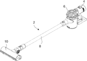
도 1은 스틱형 진공 청소기를 나타낸다.
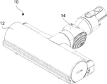
도 2는 도 1에 나타나 있는 스틱형 진공 청소기의 청소기 헤드를 나타낸다.
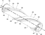
도 3은 도 2에 나타나 있는 청소기 헤드의 브러시 바아를 나타낸다.
도 4는 도 3에 나타나 있는 브러시 바아의 브러시 바아 본체의 분해도를 나타낸다.
도 5는 도 3에 나타나 있는 브러시 바아의 일부분에 대한 개략 단면도를 나타낸다.
도 6은 도 3에 나타나 있는 브러시 바아의 분해도를 나타낸다.1 shows a stick type vacuum cleaner.
Fig. 2 shows a vacuum cleaner head of the stick-type vacuum cleaner shown in Fig.
Figure 3 shows the brush bar of the cleaner head shown in Figure 2;
Fig. 4 shows an exploded view of the brush bar body of the brush bar shown in Fig. 3;
Figure 5 shows a schematic cross-sectional view of a portion of the brush bar shown in Figure 3;
Figure 6 shows an exploded view of the brush bar shown in Figure 3;
도 1은 본체(4), 사이클론 분리 장치(6), 봉(wand)(8) 및 청소기 헤드(10)를 포함하는 스틱형 진공 청소기(2)를 나타낸다.Fig. 1 shows a stick-
도 2는 분리되어 있는 청소기 헤드(10)를 나타낸다. 이 청소기 헤드(10)는 본체(12), 본체(12)에 회전 가능하게 연결되는 관절식 목부(14), 및 본체(12) 내부에 내장되는 브러시 바아(16)(도 2에서는 보이지 않고, 도 3에 분리되어 나타나 있음)를 포함한다.Fig. 2 shows a
도 3에 나타나 있는 브러시 바아(6)는, 일체형 재료로 형성되는 관형부(20)를 포함하는 브러시 바아 본체(18), 엔드 캡(22), 제 1 강모 스트립(24), 및 제 2 강모 스트립(26)을 포함한다. 브러시 바아(16)는 길이 방향 축선(X)을 갖는다.The
제 1 강모 스트립(24)은 부직물과 같은 직물로 형성되는 가요성 스트립(28)(도 5 및 6에 나타나 있음), 및 가요성 스트립(28)에 결합되어 있는 복수의 강모(30)를 포함한다. 가요성 스트립(28)은 그의 길이를 따라 실질적으로 일정한 두께(TF)를 갖는다. 가요성 스트립(28)의 두께는, 가요성 스트립(28)이 그 자신의 중량 하에서 휘어지고 예컨대 일단부에서 잡힐 때 스스로를 지탱할 수 없도록 되어 있다. 가요성 스트립(28)의 두께는 0.5 mm 미만이다. 나타나 있는 실시 형태에서, 강모(30)는 NYLON으로 만들어진다.The
제 2 강모 스트립(26)은 가요성 스트립(28)에 비해 상대적으로 강직한 강직 스트립(32)(예컨대, 플라스틱으로 만들어진 스트립), 및 스팃칭(stitching)에 의해 강직 스트립(32)에 고정되는 복수의 강모(34)를 포함한다. 나타나 있는 실시 형태에서, 강모는 탄소 섬유 강모이다.The second bristle
도 4에는 분리되어 있는 브러시 바아 본체(18)의 분해도가 나타나 있다. 브러시 바아 본체(18)는 브러시 바아 본체(18)의 원주 주위에 형성되어 있는 제 1 및 2 나선형 융기 부분(36, 38)을 가지고 있다. 각 부분(36, 38)은 브러시 바아 본체(18)의 외주 주위에 360도로 연장되어 있다. 부분(36, 38)은 180도로 서로 떨어져 있어, 브러시 바아(16)의 길이 방향 축선(X)을 따른 임의의 점에서 서로 정반대쪽에 있다.Fig. 4 shows an exploded view of the separate
각각의 제 1 및 2 채널(40, 42)이 각 부분(36, 38)의 길이를 따라 형성되어 있다. 엔드 캡(22)에 인접하는 각 채널(40, 42)의 단부는 개방되어 있다.Each of the first and
제 1 및 2 유지 립(lip)(44, 46) 형태의 유지부가 제 1 채널(40) 위로 돌출하여 유지 립(44, 46) 사이에 슬롯이 형성되도록 제 1 채널(40)의 상측 가장자리를 따라 연장되어 있다.The upper edge of the
제 1 채널(40)은 제 1 채널(40)의 길이를 따라 개방 단부(엔드 캡(22)에 가장 가까움)로부부터 멀어지면서 감소하는 깊이(DC)를 가지고 있다. 제 1 채널(40)의 길이를 따른 제 1 채널의 깊이(DC)의 변화율은 제 1 채널(40)을 따라 실질적으로 일정하다. 제 1 채널(40)의 길이를 따른 깊이(DC)의 변화율은 0.001 mm/mm 내지 0.01 mm/mm, 바람직하게는 0.002 mm/mm 내지 0.005 mm/mm 이다. 각 유지 립(44, 46)의 하측 표면과 제 1 채널(40)의 바닥 사이의 거리(DL)가 제 1 채널(40)의 길이를 따라 엔드 캡(22)에 인접한 개방 단부로부터 멀어지면서 감소하도록 제 1 및 2 유지 립(44, 46)은 그의 길이를 따라 일정한 두께 프로파일을 갖는다. 각 유지 립(44, 46)은 그의 폭을 가로질러 일정한 두께를 가질 필요는 없고, 각 유지 립(44, 46)의 폭 프로파일은 그의 길이를 따라 변하지 않는다. 제 2 유지 립(46)은 개방 단부에 인접한 곳에서 노치(47)를 갖는다.The
제 3 및 4 유지 립(48, 50)은 제 2 채널(42) 위로 돌출하여 유지 립(48, 50) 사이에 슬롯을 형성하도록 제 2 채널(42)의 상측 가장자리를 따라 연장되어 있다. 제 2 채널(42)의 깊이는 그의 길이를 따라 실질적으로 일정하고, 각 유지 립(48 50)의 하측 표면과 제 2 채널(42)의 바닥 사이의 거리가 제 2 채널(42)의 길이를 따라 변하지 않도록, 제 3 및 4 유지 립(48, 50)은 일정한 두께 프로파일을 갖는다. 제 2 채널(42)의 개방 단부는 엔드 캡(22)에 인접해 있다.The third and fourth retaining
도 5에 나타나 있는 바와 같이, 제 1 강모 스트립(24)은, 가요성 스트립(28)의 측면 가장자리가 유지 립(44, 46)의 아래에서 각각 연장되어 있고 강모(30)는 유지 립(44, 46)에 의해 형성된 슬롯을 통해 제 1 채널(40)로부터 외측으로 돌출하도록, 제 1 채널(40) 내부에 위치된다. 그러므로 제 1 강모 스트립(24)은 립(44, 46)에 의해 제 1 채널 내부에 잡혀 유지된다.5, the
도 5 및 6에 나타나 있는 심(shim)(52)이 가요성 스트립(28)을 유지 립(44, 46)의 저면과 접촉 결합 상태로 유지하도록 가요성 스트립(28)과 제 1 채널(40)의 바닥 사이에 배치된다. 심(52)의 두께(TS)는 엔드 캡(22)으로부터 멀어지는 방향으로 감소한다. 그러므로 심(52)은 그의 길이를 따라 테이퍼져 있다. 심(52)의 두께(TS)의 변화는 제 1 채널(40)의 깊이(DC)의 변화에 대응한다. 230 mm의 길이를 갖는 심(52)에 대해, 심(52)의 두께(TS)는 두꺼운 단부에서의 1.2 mm로부터 얇은 단부에서의 0.6 mm 까지 변할 수 있다. 심(52)의 길이 방향으로의 심(52)의 두께 변화율은 0.001 mm/mm 내지 0.01 mm/mm, 바람직하게는 0.002 mm/mm 내지 0.005 mm/mm 일 수 있다. 심(52)의 두께(TS)와 가요성 스트립(28)의 두께(TF)의 조합 두께는, 각 유지 립(44, 46)의 하측 표면과 제 1 채널(40)의 길이를 따르는 제 1 채널(40)의 바닥 사이의 거리(DL)와 같다. 심(52)은 심(52)의 가장 두꺼운 단부에서 탭(tab)(54)을 가지며, 이 탭은 심(52)의 나머지 부분의 상측 표면으로부터 돌출해 있다. 심(52)의 단면은 일정할 필요는 없음을 알 것이다. 일정하지 않는 단면을 갖는 심(52)의 경우, 그 심(52)의 단면 프로파일은 심이 차지하는 제 1 채널(40)의 ?부분의 단면 프로파일에 대응한다.The
이제, 브러시 바아(16)의 조립에 대해 특히 도 6을 참조하여 설명할 것이다.Now, the assembly of the
먼저, 제 2 강모 스트립(26)이 제 2 채널(42)의 개방 단부를 통해 완전히 삽입될 때까지 재료 스트립(32)의 가장자리가 유지 립(48, 50) 아래에서 제 2 채널(42)을 따라 슬라이딩하도록, 제 2 강모 스트립(26)의 강직 스트립(32)을 브러시 바아 본체(18)의 관형 부분(20)에 형성되어 있는 제 2 채널(42)의 개방 단부를 통해 삽입한다. 일단 완전히 삽입되면, 제 2 강모 스트립(26)은 제 3 및 4 유지 스트립(48, 50)에 의해 유지되고, 탄소 섬유 강모(34)는 유지 립(48, 50) 사이에 형성된 슬롯을 통해 브러시 바아 본체(18)로부터 반경 방향 외측으로 돌출한다. 강직 스트립(32)의 두께는 제 3 및 4 유지 립(48, 50)의 하측 표면 사이의 거리와 같고, 그래서 강직 스트립(32)의 상측 표면은 유지 립(48, 50)의 하측 표면과 접촉하고 강직 스트립(32)의 하측 표면은 제 2 채널(42)의 바닥과 접촉하여, 강직 스트립(32)이 제 2 채널(42) 내부에 마찰 끼워맞춤을 형성한다.First, the edge of the
둘째, 가요성 스트립(28)의 가장자리가 제 1 및 2 유지 립(44, 46) 아래에서 제 1 채널(40)을 따라 슬라이딩하고 강모(30)가 유지 립(44, 46) 사이에서 제 1 채널(40)로부터 외측으로 돌출하도록, 제 1 강모 스트립(24)의 가요성 스트립(28)이 제 1 채널(40)의 개방 단부를 통해 삽입된다. 제 1 채널(40)의 바닥과 유지 립(44, 46)의 저면 사이의 상대적으로 큰 거리(DL)에 의해, 제 1 강모 스트립(24)이 채널의 전체 길이를 따라 방해 받지 않고 밀리거나 당겨질 수 있다(즉, 가요성 스트립(28)과 제 1 채널(40)의 바닥 또는 유지 립(44, 46)의 하측 표면 사이에 마찰이 거의 없음). 일단 가요성 강모 스트립(28)이 제 1 채널(40) 안으로 완전히 삽입되면, 심(52)의 가장 얇은 단부가 가요성 스트립(28)과 제 1 채널(40)의 바닥 사이에서 제 1 채널(40) 안으로 삽입된다. 심(52)이 삽입됨에 따라, 가요성 스트립(28)은 심(52)에 의해 유지 립(44, 46) 쪽으로 반경 방향 외측으로 밀리게 된다. 심(52)이 완전히 삽입되는 지점에 도달함에 따라, 그 심은 가요성 스트립(28)을 립(44, 46)의 저면에 누르게 된다. 심(52)이 가요성 스트립(28)을 유지 립(44, 46)에 밀 때만, 심(52)과 제 1 채널(40)의 기부 사이의 큰 제한적인 마찰력이 심(52)에 가해지게 된다. 따라서, 심(52)에 가해지는 힘은 과도할 필요가 없고, 그래서 조립 중에 심(52) 또는 가요성 스트립(28)이 손상될 가능성이 낮게 된다. 일단 완전히 삽입되면, 탭(54)이 제 2 유지 립(46)에 형성되어 있는 노치(47)에 걸리게 된다. 이리하여, 심(52)(제 1 채널(40)의 길이 보다 약간 짧음)이 제 1 채널(40) 안으로 더 밀려 들어가는 것이 방지된다.Second, the edge of the
상기 구성의 이점은, 제 2 강모 스트립(26)의 강직 스트립(32)과는 달리 가요성 스트립(28)은 제 1 채널(40) 안으로 삽입될 때의 마찰력을 견디도록 설계될 필요가 없기 때문에 가요성 스트립(28)은 매우 가요적일 수 있다는 것이다. 가요성 스트립(28)은 또한 일정한 두께를 가질 수 있다. 그러므로 강모 스트립(26)은, 비교적 간단하고 저렴한 제조 공정을 사용하여 만들어질 수 있다. 상기 구성은 제 1 채널(40)의 길이가 비교적 길 때 특히 유리한데, 그러한 경우, 마찰 끼워맞춤을 갖는 강모 스트립의 삽입으로 발생되는 비교적 큰 마찰력이 회피된다. 이리하여, 그렇지 않은 경우 보다 훨씬 더 긴 채널이 사용될 수 있다. 나타나 있는 실시 형태에서, 심(52)은 가요성 스트립(28) 보다 강직하고 또한 충분한 강직성을 가지고 있어, 심(52)은 제 1 채널(40) 안으로 완전히 밀려 들아갈 때 과도하게 변형되지 않는다.The advantage of this configuration is that since the
상기 구성의 추가 이점은, 심(52)은 제 2 강모 스트립(26)에 대항 중량을 제공하도록 구성될 수 있다는 것인데, 설명된 실시 형태에서 그 대항 중량은 제 1 강모 스트립(24) 보다 무겁다. 그러므로, 심(52)은 길이 방향 축선(X) 주위로 브러시 바아(16)의 균형을 잡기 위해 사용될 수 있다.A further advantage of this arrangement is that the
일단 제 1 및 2 강모 스트립(24, 26)이 브러시 바아 본체(18)의 관형부(20)와 조립되면, 엔드 캡(22)이 관형부(20)의 단부에서 제자리에 고정된다. 엔드 캡(22)은 밀기 끼워맞춤일 수 있고/있거나 접착 및/또는 용접으로 고정될 수 있다. 엔드 캡(22)은 제 1 및 2 강모 스트립(24, 26) 및 심(52)을 채널(40, 42) 내부 제자리에 유지시킨다.Once the first and second bristle strips 24 and 26 are assembled with the
대안적인 실시 형태에서, 심은 양 세트의 강모 스트립을 위해 사용될 수 있음을 알 것이다.In an alternative embodiment, the shim may be used for both sets of bristle strips.
제 1 채널의 적어도 일부분은 제 1 채널의 깊이가 감소하는 것과 동일한 방향으로 감소하는 폭을 가질 수 있고, 심의 폭은 제 1 채널의 폭의 감소에 대응하는 양 만큼 감소하는 폭을 갖는다. 이는 심의 삽입에 더 도움을 준다.At least a portion of the first channel may have a width decreasing in the same direction as the depth of the first channel decreases, and the width of the padding has a width decreasing by an amount corresponding to a decrease in the width of the first channel. This helps the insertion of the heart.
Claims (19)
대체로 상기 브러시 바아의 길이 방향으로 연장되어 있는 채널, 및 상기 채널의 각 측의 일부분을 따라 제공되어 있고 상기 채널의 바닥으로부터 이격되어 있는 적어도 하나의 유지부를 갖는 브러시 바아 본체 - 상기 채널은 변하는 부분을 가지며, 이 변하는 부분에서 상기 채널의 깊이는 상기 변하는 부분의 일 단부로부터 상기 채널의 길이 방향으로 감소함 -;
가요성 스트립 및 교란기를 포함하는 교란 요소 - 상기 가요성 스트립은, 상기 유지부가 가요성 스트립을 상기 채널 안에 유지하고 또한 상기 교란기가 채널로부터 반경 방향 외측으로 연장되도록, 상기 채널에 배치되고 각 유지부와 채널의 바닥 사이에서 연장되어 있음 -; 및
상기 가요성 스트립이 각 유지부와 접촉한 상태로 유지되도록 상기 가요성 스트립과 채널의 바닥 사이에 배치되는 심(shim)을 포함하고,
상기 심은 변하는 부분을 가지며, 이 변하는 부분에서 두께 프로파일은 상기 채널의 깊이 감소에 대응하는 양 만큼 상기 심의 길이 방향으로 감소하는, 청소기 헤드용 브러시 바아.As a brush bar for a cleaner head,
A brush bar body having a channel generally extending in the longitudinal direction of the brush bar and at least one retaining portion provided along a portion of each side of the channel and spaced from the bottom of the channel, Wherein the depth of the channel in the varying portion decreases from one end of the varying portion in the longitudinal direction of the channel;
A disturbing element comprising a flexible strip and a disturbing element, the flexible strip being arranged in the channel such that the retaining portion holds the flexible strip in the channel and the disturbing element extends radially outwardly from the channel, Extending between the bottom of the channel and the bottom of the channel; And
And a shim disposed between the bottom of the channel and the flexible strip such that the flexible strip remains in contact with the respective retaining portion,
The shim having a varying portion in which the thickness profile decreases in the longitudinal direction of the shim by an amount corresponding to a depth reduction of the channel.
상기 심의 길이 방향으로 심의 상기 변하는 부분의 두께 프로파일의 변화율은 0.001 mm/mm 내지 0.01 mm/mm인, 청소기 헤드용 브러시 바아.The method according to claim 1,
Wherein the rate of change of the thickness profile of the varying portion of the shim in the longitudinal direction of the shim is 0.001 mm / mm to 0.01 mm / mm.
상기 채널의 상기 변하는 부분은 상기 채널의 길이의 적어도 절반을 따라 연장되어 있는, 청소기 헤드용 브러시 바아.3. The method according to claim 1 or 2,
Wherein the varying portion of the channel extends along at least half of the length of the channel.
상기 가요성 스트립의 두께 프로파일은 가요성 스트립의 길이를 따라 실질적으로 일정한, 청소기 헤드용 브러시 바아.4. The method according to any one of claims 1 to 3,
Wherein the thickness profile of the flexible strip is substantially constant along the length of the flexible strip.
상기 유지부는 상기 채널의 일측의 적어도 일부분을 따라 연장되어 있는 제 1 유지 립(lip) 및 상기 채널의 반대측의 적어도 일부분을 따라 연장되어 있는 제 2 유지 립을 포함하는, 청소기 헤드용 브러시 바아.5. The method according to any one of claims 1 to 4,
Wherein the retaining portion comprises a first retaining lip extending along at least a portion of one side of the channel and a second retaining lip extending along at least a portion of the opposite side of the channel.
각 유지 립과 채널의 상기 변하는 부분을 따르는 채널의 바닥 사이의 거리는 채널의 길이 방향으로 감소하는, 청소기 헤드용 브러시 바아.6. The method of claim 5,
Wherein the distance between each of the retaining lip and the bottom of the channel along the varying portion of the channel decreases in the longitudinal direction of the channel.
상기 채널은 상기 가요성 스트립과 심을 채널 안으로 삽입하기 위해 채널의 일단부 쪽에서 개구를 가지고 있는, 청소기 헤드용 브러시 바아.7. The method according to any one of claims 1 to 6,
The channel having an opening at one end of the channel for inserting the flexible strip and shim into the channel.
상기 변하는 부분을 따르는 상기 채널의 바닥과 각 유지부 사이의 거리는 상기 개구로부터 멀어지는 방향으로 감소하는, 청소기 헤드용 브러시 바아.8. The method of claim 7,
Wherein the distance between the bottom of each channel and the respective retaining along the varying portion decreases in a direction away from the opening.
상기 교란기 스트립과 심을 상기 채널 내부에 고정하기 위해 채널의 개방 단부에 고정되는 유지기를 더 포함하는, 청소기 헤드용 브러시 바아.9. The method according to claim 7 or 8,
Further comprising a retainer secured to an open end of the channel to secure the disturbing strip and shim within the channel.
상기 유지기는 상기 브러시 바아 본체의 단부에 고정되는 캡을 포함하는, 청소기 헤드용 브러시 바아.10. The method of claim 9,
Wherein the retainer comprises a cap secured to an end of the brush bar body.
상기 채널의 상기 변하는 부분의 폭은 채널의 길이 방향으로 감소하고, 상기 심의 상기 변하는 부분의 폭은 채널 폭의 감소에 대응하는 양 만큼 심의 상기 변하는 부분을 따라 감소하는, 청소기 헤드용 브러시 바아.11. The method according to any one of claims 1 to 10,
Wherein the width of the varying portion of the channel decreases in a longitudinal direction of the channel and the width of the varying portion of the shim decreases along the varying portion of the shim by an amount corresponding to a decrease in channel width.
상기 교란기는 상기 가요성 스트립에 고정되는 강모를 포함하는, 청소기 헤드용 브러시 바아.12. The method according to any one of claims 1 to 11,
Wherein the disturbing device comprises a bristle fixed to the flexible strip.
상기 가요성 스트립은 직물을 포함하는, 청소기 헤드용 브러시 바아.13. The method of claim 12,
Wherein the flexible strip comprises a fabric.
상기 채널은 적어도 180도로 나선으로 연장되어 있는, 청소기 헤드용 브러시 바아.14. The method according to any one of claims 1 to 13,
Wherein the channel extends at least 180 degrees in a spiral.
대체로 상기 브러시 바아의 길이 방향으로 연장되어 있는 채널, 및 상기 채널의 각 측의 일부분을 따라 제공되어 있고 상기 채널의 바닥으로부터 이격되어 있는 적어도 하나의 유지부를 갖는 브러시 바아 본체를 제공하는 단계 - 상기 채널은 변하는 부분을 가지며, 이 변하는 부분에서 상기 채널의 깊이는 상기 변하는 부분의 일 단부로부터 상기 채널의 길이 방향으로 감소함 -;
가요성 스트립이 상기 채널에 배치되고 각 유지부와 채널의 바닥 사이에서 연장되며 또한 교란기가 채널로부터 반경 방향 외측으로 연장되도록, 가요성 스트립과 교란기를 포함하는 교란기 요소를 상기 채널 안으로 삽입하는 단계; 및
상기 가요성 스트립이 가압되어 각 유지부와 접촉하도록 상기 가요성 스트립과 채널의 바닥 사이에 심(shim)을 삽입하는 단계를 포함하고,
상기 심은 변하는 부분을 가지며, 이 변하는 부분에서 두께 프로파일은 상기 채널의 깊이 감소에 대응하는 양 만큼 상기 심의 길이 방향으로 감소하는, 브러시 바아 제조 방법.A method of manufacturing a brush bar,
Providing a brush bar body having a channel extending generally in a longitudinal direction of the brush bar and at least one retaining portion provided along a portion of each side of the channel and spaced from a bottom of the channel, Wherein the depth of the channel in the varying portion decreases from one end of the varying portion in the longitudinal direction of the channel;
Inserting into the channel a disturbing element comprising a flexible strip and a disturbance such that a flexible strip is disposed in the channel and extends between the bottom of each retaining portion and the channel and the disturbance extends radially outward from the channel ; And
Inserting a shim between the flexible strip and the bottom of the channel such that the flexible strip is pressed into contact with each of the retaining portions,
Wherein the shim has a varying portion in which the thickness profile decreases in the longitudinal direction of the shim by an amount corresponding to a depth reduction of the channel.
상기 브러시 바아는 제 2 항 내지 제 15 항에 기재되어 있는 사항들 중의 하나 이상을 포함하는, 브러시 바아 제조 방법.18. The method of claim 17,
Wherein the brush bar comprises one or more of the items recited in claims 2 to 15.
상기 채널은 채널의 일단부 쪽에서 개구를 가지며, 상기 교란기 스트립과 심을 상기 채널 내부에 유지하기 위해 개방 단부에 유지기를 고정하는 단계를 더 포함하는 브러시 바아 제조 방법.The method according to claim 17 or 18,
The channel having an opening at one end of the channel and securing the retainer at an open end to retain the stirrup strip and shim within the channel.
Applications Claiming Priority (3)
| Application Number | Priority Date | Filing Date | Title |
|---|---|---|---|
| GB1601216.3 | 2016-01-22 | ||
| GB1601216.3A GB2546540B (en) | 2016-01-22 | 2016-01-22 | Brushbar, cleaner head and method of manufacture of a brushbar |
| PCT/GB2016/053853 WO2017125704A1 (en) | 2016-01-22 | 2016-12-08 | Brushbar, cleaner head and method of manufacture of a brushbar |
Publications (1)
| Publication Number | Publication Date |
|---|---|
| KR20180098657A true KR20180098657A (en) | 2018-09-04 |
Family
ID=55534787
Family Applications (1)
| Application Number | Title | Priority Date | Filing Date |
|---|---|---|---|
| KR1020187021961A Ceased KR20180098657A (en) | 2016-01-22 | 2016-12-08 | Brush Bar, Cleaner Head, and Brush Bar Manufacturing Method |
Country Status (8)
| Country | Link |
|---|---|
| US (1) | US10426306B2 (en) |
| EP (1) | EP3405085A1 (en) |
| JP (1) | JP6435354B2 (en) |
| KR (1) | KR20180098657A (en) |
| CN (1) | CN106993985A (en) |
| AU (1) | AU2016387301B2 (en) |
| GB (1) | GB2546540B (en) |
| WO (1) | WO2017125704A1 (en) |
Families Citing this family (19)
| Publication number | Priority date | Publication date | Assignee | Title |
|---|---|---|---|---|
| US11992172B2 (en) | 2018-10-19 | 2024-05-28 | Sharkninja Operating Llc | Agitator for a surface treatment apparatus and a surface treatment apparatus having the same |
| US11647881B2 (en) | 2015-10-21 | 2023-05-16 | Sharkninja Operating Llc | Cleaning apparatus with combing unit for removing debris from cleaning roller |
| CN208693165U (en) | 2015-10-21 | 2019-04-05 | 尚科宁家运营有限公司 | Surface cleaning head with dual rotary agitators |
| CN118806047A (en) * | 2016-09-09 | 2024-10-22 | 尚科宁家运营有限公司 | Hair removal mixer |
| CN110494062B (en) | 2017-03-10 | 2022-01-25 | 尚科宁家运营有限公司 | Blender with remover and hair removal |
| US11202542B2 (en) | 2017-05-25 | 2021-12-21 | Sharkninja Operating Llc | Robotic cleaner with dual cleaning rollers |
| US10820772B2 (en) | 2017-09-15 | 2020-11-03 | Omachron Intellectual Property Inc. | Surface cleaning apparatus |
| GB2569313B (en) | 2017-12-12 | 2020-10-28 | Dyson Technology Ltd | A cleaner head for a vacuum cleaner |
| CN109008838A (en) * | 2018-08-29 | 2018-12-18 | 宁波德昌电机制造有限公司 | A kind of carpet cleaner |
| USD912344S1 (en) * | 2018-08-29 | 2021-03-02 | Samsung Electronics Co., Ltd. | Cleaner |
| GB201815655D0 (en) | 2018-09-26 | 2018-11-07 | Dyson Technology Ltd | Cleaner head for a vacuum cleaner |
| JP7152837B2 (en) * | 2018-10-19 | 2022-10-13 | シャークニンジャ オペレーティング エルエルシー | Stirrer for surface treatment equipment and surface treatment equipment having the same |
| GB2584446B (en) * | 2019-06-03 | 2021-09-22 | Dyson Technology Ltd | A cleaner head for a vacuum cleaner |
| GB2588157B (en) * | 2019-10-10 | 2022-01-05 | Dyson Technology Ltd | Cleaner head for a vacuum cleaning appliance |
| CN220631979U (en) | 2020-07-09 | 2024-03-22 | 米沃奇电动工具公司 | Accessory for use with a vacuum cleaner |
| WO2022026728A1 (en) * | 2020-07-29 | 2022-02-03 | Sharkninja Operating Llc | Nozzle for a surface treatment apparatus and a surface treatment apparatus having the same |
| EP4716491A1 (en) | 2023-05-23 | 2026-04-01 | SharkNinja Operating LLC | Cleaning apparatus |
| USD1107355S1 (en) * | 2023-07-18 | 2025-12-23 | Lg Electronics Inc. | Vacuum cleaner |
| JP1823166S (en) * | 2023-07-18 | 2026-04-01 | vacuum cleaner |
Family Cites Families (26)
| Publication number | Priority date | Publication date | Assignee | Title |
|---|---|---|---|---|
| US1866118A (en) | 1929-01-28 | 1932-07-05 | Hoover Co | Suction cleaner |
| NL32972C (en) | 1931-07-18 | |||
| US2261781A (en) * | 1937-12-31 | 1941-11-04 | Hoover Co | Suction cleaner |
| US2271556A (en) | 1938-12-23 | 1942-02-03 | Hoover Co | Suction cleaner |
| US2767418A (en) * | 1951-07-26 | 1956-10-23 | William A Lombardi | Brush construction |
| GB790826A (en) | 1955-09-19 | 1958-02-19 | Osborn Mfg Co | Improvements in or relating to rotary brushes |
| US3225374A (en) * | 1963-08-26 | 1965-12-28 | Singer Co | Beater-brush roller for vacuum cleaner |
| US3820189A (en) * | 1972-12-11 | 1974-06-28 | E Roth | Brush adaptor for vacuuming |
| US3909871A (en) * | 1973-07-18 | 1975-10-07 | Superior Brush Co | Rotary brush assembly |
| JPS62127662A (en) * | 1985-11-29 | 1987-06-09 | Dai Ichi Pure Chem Co Ltd | Vertical slab type electrophoresis device |
| JPH04314411A (en) | 1991-01-23 | 1992-11-05 | Tokyo Electric Co Ltd | Vacuum cleaner suction body |
| US5495634A (en) * | 1994-06-30 | 1996-03-05 | Bruns Brush Inc. (Ohio Corporation) | Vacuum sweeper roller brush |
| JP3090397B2 (en) | 1994-07-28 | 2000-09-18 | 東芝テック株式会社 | Rotary cleaning body |
| JP3642357B2 (en) | 1995-10-27 | 2005-04-27 | 株式会社コーワ | Rotating rotor of floor nozzle for vacuum cleaner |
| DE19728380C1 (en) * | 1997-07-03 | 1999-01-14 | Kaercher Gmbh & Co Alfred | Brush roller for cleaning unit with helix bristle strip running along roller periphery |
| DE20001579U1 (en) | 2000-01-29 | 2001-04-05 | BTD Barteldrees GmbH & Co., 33334 Gütersloh | Round brushes |
| JP2005046229A (en) | 2003-07-30 | 2005-02-24 | Toshiba Tec Corp | Rotary cleaning body and suction port body of electric vacuum cleaner using this rotary cleaning body |
| US7140062B1 (en) | 2003-10-23 | 2006-11-28 | Fu Yu Chen | Brush structure for vacuum cleaner |
| JP2007195631A (en) * | 2006-01-24 | 2007-08-09 | Funai Electric Co Ltd | Brush for vacuum cleaner |
| JP2008061785A (en) | 2006-09-06 | 2008-03-21 | Kowa Co Ltd | Rotating rotor, floor suction tool for vacuum cleaner, vacuum cleaner and air conditioner |
| KR101136860B1 (en) | 2010-04-28 | 2012-04-20 | 삼성전자주식회사 | Brush Assembly for Vacuum Cleaner |
| DE102011116419B4 (en) * | 2011-10-18 | 2013-07-25 | Stein & Co. Gmbh | Brush roller of a floor care device |
| JP6376639B2 (en) * | 2013-11-01 | 2018-08-22 | 株式会社コーワ | Rotary cleaning body, vacuum cleaner suction tool and vacuum cleaner |
| KR20150094067A (en) | 2014-02-10 | 2015-08-19 | 주식회사 디에스티로봇 | Agitator module for cleaner |
| GB2526512B (en) * | 2014-03-19 | 2017-07-26 | Dyson Technology Ltd | Cleaning appliance |
| JP2015198856A (en) | 2014-04-10 | 2015-11-12 | 株式会社コーワ | Suction tool of vacuum cleaner |
-
2016
- 2016-01-22 GB GB1601216.3A patent/GB2546540B/en not_active Expired - Fee Related
- 2016-12-08 WO PCT/GB2016/053853 patent/WO2017125704A1/en not_active Ceased
- 2016-12-08 AU AU2016387301A patent/AU2016387301B2/en not_active Ceased
- 2016-12-08 EP EP16812791.8A patent/EP3405085A1/en not_active Withdrawn
- 2016-12-08 KR KR1020187021961A patent/KR20180098657A/en not_active Ceased
-
2017
- 2017-01-19 US US15/410,429 patent/US10426306B2/en not_active Expired - Fee Related
- 2017-01-20 CN CN201710044860.9A patent/CN106993985A/en active Pending
- 2017-01-20 JP JP2017008260A patent/JP6435354B2/en not_active Expired - Fee Related
Also Published As
| Publication number | Publication date |
|---|---|
| JP6435354B2 (en) | 2018-12-05 |
| GB2546540A (en) | 2017-07-26 |
| AU2016387301A1 (en) | 2018-07-19 |
| AU2016387301B2 (en) | 2018-12-06 |
| GB2546540B (en) | 2018-07-18 |
| EP3405085A1 (en) | 2018-11-28 |
| CN106993985A (en) | 2017-08-01 |
| WO2017125704A1 (en) | 2017-07-27 |
| JP2017127640A (en) | 2017-07-27 |
| GB201601216D0 (en) | 2016-03-09 |
| US10426306B2 (en) | 2019-10-01 |
| US20170209008A1 (en) | 2017-07-27 |
Similar Documents
| Publication | Publication Date | Title |
|---|---|---|
| KR20180098657A (en) | Brush Bar, Cleaner Head, and Brush Bar Manufacturing Method | |
| US20210068602A1 (en) | Cleaner head for a vacuum cleaner | |
| US20260047732A1 (en) | Agitator with hair removal | |
| JP2023536277A (en) | Nozzle for surface treatment equipment and surface treatment equipment having same nozzle | |
| US6230356B1 (en) | Toothbrush | |
| US5327611A (en) | Hair brush | |
| US8568049B2 (en) | Mascara brush with eyelash retaining member | |
| US6477731B2 (en) | Mop with self-contained wringer | |
| US20150343155A1 (en) | Fastening element and syringe | |
| US9078514B2 (en) | Brush cap for cleaning | |
| US20190191945A1 (en) | Toilet hook | |
| US20090236867A1 (en) | Apparatus facilitating the collection of marker cones | |
| US2728933A (en) | Vacuum cleaner nozzle attachments | |
| US20100132147A1 (en) | Mop head | |
| US2652959A (en) | Wedge type curtain rod guide | |
| JP4463831B2 (en) | Strength reinforcement rod and cleaning method | |
| JP2001275886A (en) | Toilet brush | |
| US819934A (en) | Brush. | |
| GB2413260A (en) | A curtain heading system and glider therefore |
Legal Events
| Date | Code | Title | Description |
|---|---|---|---|
| A201 | Request for examination | ||
| PA0105 | International application |
Patent event date: 20180730 Patent event code: PA01051R01D Comment text: International Patent Application |
|
| PA0201 | Request for examination | ||
| PG1501 | Laying open of application | ||
| E902 | Notification of reason for refusal | ||
| PE0902 | Notice of grounds for rejection |
Comment text: Notification of reason for refusal Patent event date: 20190625 Patent event code: PE09021S01D |
|
| E601 | Decision to refuse application | ||
| PE0601 | Decision on rejection of patent |
Patent event date: 20191202 Comment text: Decision to Refuse Application Patent event code: PE06012S01D Patent event date: 20190625 Comment text: Notification of reason for refusal Patent event code: PE06011S01I |