KR20180098652A - Construction material container - Google Patents
Construction material container Download PDFInfo
- Publication number
- KR20180098652A KR20180098652A KR1020187021902A KR20187021902A KR20180098652A KR 20180098652 A KR20180098652 A KR 20180098652A KR 1020187021902 A KR1020187021902 A KR 1020187021902A KR 20187021902 A KR20187021902 A KR 20187021902A KR 20180098652 A KR20180098652 A KR 20180098652A
- Authority
- KR
- South Korea
- Prior art keywords
- reservoir
- container
- containers
- build
- construction materials
- Prior art date
- Legal status (The legal status is an assumption and is not a legal conclusion. Google has not performed a legal analysis and makes no representation as to the accuracy of the status listed.)
- Ceased
Links
Images


Classifications
-
- B—PERFORMING OPERATIONS; TRANSPORTING
- B29—WORKING OF PLASTICS; WORKING OF SUBSTANCES IN A PLASTIC STATE IN GENERAL
- B29C—SHAPING OR JOINING OF PLASTICS; SHAPING OF MATERIAL IN A PLASTIC STATE, NOT OTHERWISE PROVIDED FOR; AFTER-TREATMENT OF THE SHAPED PRODUCTS, e.g. REPAIRING
- B29C64/00—Additive manufacturing, i.e. manufacturing of three-dimensional [3D] objects by additive deposition, additive agglomeration or additive layering, e.g. by 3D printing, stereolithography or selective laser sintering
- B29C64/30—Auxiliary operations or equipment
- B29C64/307—Handling of material to be used in additive manufacturing
- B29C64/321—Feeding
- B29C64/329—Feeding using hoppers
-
- B—PERFORMING OPERATIONS; TRANSPORTING
- B29—WORKING OF PLASTICS; WORKING OF SUBSTANCES IN A PLASTIC STATE IN GENERAL
- B29C—SHAPING OR JOINING OF PLASTICS; SHAPING OF MATERIAL IN A PLASTIC STATE, NOT OTHERWISE PROVIDED FOR; AFTER-TREATMENT OF THE SHAPED PRODUCTS, e.g. REPAIRING
- B29C64/00—Additive manufacturing, i.e. manufacturing of three-dimensional [3D] objects by additive deposition, additive agglomeration or additive layering, e.g. by 3D printing, stereolithography or selective laser sintering
- B29C64/20—Apparatus for additive manufacturing; Details thereof or accessories therefor
- B29C64/255—Enclosures for the building material, e.g. powder containers
-
- B—PERFORMING OPERATIONS; TRANSPORTING
- B22—CASTING; POWDER METALLURGY
- B22F—WORKING METALLIC POWDER; MANUFACTURE OF ARTICLES FROM METALLIC POWDER; MAKING METALLIC POWDER; APPARATUS OR DEVICES SPECIALLY ADAPTED FOR METALLIC POWDER
- B22F1/00—Metallic powder; Treatment of metallic powder, e.g. to facilitate working or to improve properties
- B22F1/14—Treatment of metallic powder
- B22F1/145—Chemical treatment, e.g. passivation or decarburisation
- B22F1/147—Making a dispersion
-
- B—PERFORMING OPERATIONS; TRANSPORTING
- B22—CASTING; POWDER METALLURGY
- B22F—WORKING METALLIC POWDER; MANUFACTURE OF ARTICLES FROM METALLIC POWDER; MAKING METALLIC POWDER; APPARATUS OR DEVICES SPECIALLY ADAPTED FOR METALLIC POWDER
- B22F12/00—Apparatus or devices specially adapted for additive manufacturing; Auxiliary means for additive manufacturing; Combinations of additive manufacturing apparatus or devices with other processing apparatus or devices
- B22F12/50—Means for feeding of material, e.g. heads
- B22F12/52—Hoppers
-
- B—PERFORMING OPERATIONS; TRANSPORTING
- B22—CASTING; POWDER METALLURGY
- B22F—WORKING METALLIC POWDER; MANUFACTURE OF ARTICLES FROM METALLIC POWDER; MAKING METALLIC POWDER; APPARATUS OR DEVICES SPECIALLY ADAPTED FOR METALLIC POWDER
- B22F3/00—Manufacture of workpieces or articles from metallic powder characterised by the manner of compacting or sintering; Apparatus specially adapted therefor ; Presses and furnaces
- B22F3/004—Filling molds with powder
-
- B22F3/1055—
-
- B—PERFORMING OPERATIONS; TRANSPORTING
- B29—WORKING OF PLASTICS; WORKING OF SUBSTANCES IN A PLASTIC STATE IN GENERAL
- B29C—SHAPING OR JOINING OF PLASTICS; SHAPING OF MATERIAL IN A PLASTIC STATE, NOT OTHERWISE PROVIDED FOR; AFTER-TREATMENT OF THE SHAPED PRODUCTS, e.g. REPAIRING
- B29C64/00—Additive manufacturing, i.e. manufacturing of three-dimensional [3D] objects by additive deposition, additive agglomeration or additive layering, e.g. by 3D printing, stereolithography or selective laser sintering
- B29C64/20—Apparatus for additive manufacturing; Details thereof or accessories therefor
-
- B—PERFORMING OPERATIONS; TRANSPORTING
- B33—ADDITIVE MANUFACTURING TECHNOLOGY
- B33Y—ADDITIVE MANUFACTURING, i.e. MANUFACTURING OF THREE-DIMENSIONAL [3D] OBJECTS BY ADDITIVE DEPOSITION, ADDITIVE AGGLOMERATION OR ADDITIVE LAYERING, e.g. BY 3D PRINTING, STEREOLITHOGRAPHY OR SELECTIVE LASER SINTERING
- B33Y30/00—Apparatus for additive manufacturing; Details thereof or accessories therefor
-
- B—PERFORMING OPERATIONS; TRANSPORTING
- B33—ADDITIVE MANUFACTURING TECHNOLOGY
- B33Y—ADDITIVE MANUFACTURING, i.e. MANUFACTURING OF THREE-DIMENSIONAL [3D] OBJECTS BY ADDITIVE DEPOSITION, ADDITIVE AGGLOMERATION OR ADDITIVE LAYERING, e.g. BY 3D PRINTING, STEREOLITHOGRAPHY OR SELECTIVE LASER SINTERING
- B33Y40/00—Auxiliary operations or equipment, e.g. for material handling
-
- B—PERFORMING OPERATIONS; TRANSPORTING
- B33—ADDITIVE MANUFACTURING TECHNOLOGY
- B33Y—ADDITIVE MANUFACTURING, i.e. MANUFACTURING OF THREE-DIMENSIONAL [3D] OBJECTS BY ADDITIVE DEPOSITION, ADDITIVE AGGLOMERATION OR ADDITIVE LAYERING, e.g. BY 3D PRINTING, STEREOLITHOGRAPHY OR SELECTIVE LASER SINTERING
- B33Y99/00—Subject matter not provided for in other groups of this subclass
-
- C—CHEMISTRY; METALLURGY
- C03—GLASS; MINERAL OR SLAG WOOL
- C03B—MANUFACTURE, SHAPING, OR SUPPLEMENTARY PROCESSES
- C03B19/00—Other methods of shaping glass
- C03B19/01—Other methods of shaping glass by progressive fusion or sintering of powdered glass onto a shaping substrate, i.e. accretion, e.g. plasma oxidation deposition
-
- B—PERFORMING OPERATIONS; TRANSPORTING
- B22—CASTING; POWDER METALLURGY
- B22F—WORKING METALLIC POWDER; MANUFACTURE OF ARTICLES FROM METALLIC POWDER; MAKING METALLIC POWDER; APPARATUS OR DEVICES SPECIALLY ADAPTED FOR METALLIC POWDER
- B22F1/00—Metallic powder; Treatment of metallic powder, e.g. to facilitate working or to improve properties
- B22F1/10—Metallic powder containing lubricating or binding agents; Metallic powder containing organic material
- B22F1/107—Metallic powder containing lubricating or binding agents; Metallic powder containing organic material containing organic material comprising solvents, e.g. for slip casting
-
- B—PERFORMING OPERATIONS; TRANSPORTING
- B22—CASTING; POWDER METALLURGY
- B22F—WORKING METALLIC POWDER; MANUFACTURE OF ARTICLES FROM METALLIC POWDER; MAKING METALLIC POWDER; APPARATUS OR DEVICES SPECIALLY ADAPTED FOR METALLIC POWDER
- B22F10/00—Additive manufacturing of workpieces or articles from metallic powder
- B22F10/10—Formation of a green body
- B22F10/14—Formation of a green body by jetting of binder onto a bed of metal powder
-
- B—PERFORMING OPERATIONS; TRANSPORTING
- B22—CASTING; POWDER METALLURGY
- B22F—WORKING METALLIC POWDER; MANUFACTURE OF ARTICLES FROM METALLIC POWDER; MAKING METALLIC POWDER; APPARATUS OR DEVICES SPECIALLY ADAPTED FOR METALLIC POWDER
- B22F10/00—Additive manufacturing of workpieces or articles from metallic powder
- B22F10/20—Direct sintering or melting
- B22F10/28—Powder bed fusion, e.g. selective laser melting [SLM] or electron beam melting [EBM]
-
- B—PERFORMING OPERATIONS; TRANSPORTING
- B22—CASTING; POWDER METALLURGY
- B22F—WORKING METALLIC POWDER; MANUFACTURE OF ARTICLES FROM METALLIC POWDER; MAKING METALLIC POWDER; APPARATUS OR DEVICES SPECIALLY ADAPTED FOR METALLIC POWDER
- B22F12/00—Apparatus or devices specially adapted for additive manufacturing; Auxiliary means for additive manufacturing; Combinations of additive manufacturing apparatus or devices with other processing apparatus or devices
- B22F12/50—Means for feeding of material, e.g. heads
- B22F12/55—Two or more means for feeding material
-
- B—PERFORMING OPERATIONS; TRANSPORTING
- B22—CASTING; POWDER METALLURGY
- B22F—WORKING METALLIC POWDER; MANUFACTURE OF ARTICLES FROM METALLIC POWDER; MAKING METALLIC POWDER; APPARATUS OR DEVICES SPECIALLY ADAPTED FOR METALLIC POWDER
- B22F12/00—Apparatus or devices specially adapted for additive manufacturing; Auxiliary means for additive manufacturing; Combinations of additive manufacturing apparatus or devices with other processing apparatus or devices
- B22F12/70—Gas flow means
-
- B22F2003/1056—
-
- Y—GENERAL TAGGING OF NEW TECHNOLOGICAL DEVELOPMENTS; GENERAL TAGGING OF CROSS-SECTIONAL TECHNOLOGIES SPANNING OVER SEVERAL SECTIONS OF THE IPC; TECHNICAL SUBJECTS COVERED BY FORMER USPC CROSS-REFERENCE ART COLLECTIONS [XRACs] AND DIGESTS
- Y02—TECHNOLOGIES OR APPLICATIONS FOR MITIGATION OR ADAPTATION AGAINST CLIMATE CHANGE
- Y02P—CLIMATE CHANGE MITIGATION TECHNOLOGIES IN THE PRODUCTION OR PROCESSING OF GOODS
- Y02P10/00—Technologies related to metal processing
- Y02P10/25—Process efficiency
Landscapes
- Engineering & Computer Science (AREA)
- Chemical & Material Sciences (AREA)
- Materials Engineering (AREA)
- Manufacturing & Machinery (AREA)
- Mechanical Engineering (AREA)
- Physics & Mathematics (AREA)
- Optics & Photonics (AREA)
- Dispersion Chemistry (AREA)
- Chemical Kinetics & Catalysis (AREA)
- General Chemical & Material Sciences (AREA)
- Plasma & Fusion (AREA)
- Organic Chemistry (AREA)
Abstract
3D 프린팅 축조 재료 용기(1)가 제공된다. 이 용기(1)는 저장소(3) 및 보강 구조체(4)를 포함한다. 이 저장소는 축조 재료를 보유하는 것이다. 보강 구조체는 적어도 하나의 선택된 위치에서 저장소에 부착된다. 저장소 및 보강 구조체는 상대적으로 편평한 구성에서 저장소가 축조 재료로 충전가능한 사용시 구성으로의 용기의 재구성을 허용하는 것이다.A 3D printing building material container (1) is provided. The container (1) includes a reservoir (3) and a reinforcing structure (4). The reservoir is to hold the building material. The reinforcement structure is attached to the reservoir in at least one selected location. The reservoir and the reinforcement structure allow the reconstitution of the container into a configuration during use in which the reservoir can be filled with the build-up material in a relatively flat configuration.
Description
3차원(3D) 프린팅과 같은 적층 가공 기술은 컴퓨터 제어 하에서 3D 물체가 층(layer) 단위로 생성되는 적층 공정을 통해, 디지털 3D 모델로부터 거의 모든 형상의 3D 물체를 제조하는 기술에 관련된다. 축조 재료(build material), 침착 기술, 및 이 축조 재료로부터 3D 물체를 형성하는 공정이 상이한, 매우 다양한 적층 가공 기술이 발전되어왔다. 이러한 기술은 자외선을 광경화성(photopolymer) 수지에 인가하는 것에서부터 분말 형태의 반결정질 열가소성 물질을 용융하는 것, 금속 분말의 전자 빔 용융에까지 이를 수도 있다.Background of the Invention Lamination techniques, such as three-dimensional (3D) printing, relate to techniques for fabricating 3D objects of almost any shape from a digital 3D model through a lamination process in which 3D objects are created layer by layer under computer control. A wide variety of stacking techniques have been developed, with different build materials, deposition techniques, and processes for forming 3D objects from these build materials. This technique can range from applying ultraviolet light to photopolymer resins to melting powdery semicrystalline thermoplastics, to electron beam melting of metal powders.
적층 가공 공정은 일반적으로 제조될 3D 물체의 디지털 표시로 시작한다. 이러한 디지털 표시는 컴퓨터 소프트웨어에 의해 가상으로 층으로 분할(slice)되거나, 사전-분할된 포맷(format)으로 제공될 수도 있다. 각 층은 소망된 물체의 단면을 나타내고, 일부 경우에는 3D 프린터로 알려진 적층 가공 장비로 보내지며, 여기서 이러한 각 층은 이전에 축조된 층 상에 축조된다. 이러한 공정은 물체가 완성될 때까지 반복되고, 이에 의해 물체를 층 단위로 축조한다. 일부 이용가능한 기술은 금속을 직접 인쇄하는 반면, 다른 기술은 물체의 새로운 단면을 생성하기 위해 그 다음에 선택적으로 고화될 수 있는 추가의 층을 형성하도록 재코팅 공정을 사용한다.The lamination process usually begins with a digital representation of the 3D object to be fabricated. Such a digital representation may be sliced into layers virtually by computer software, or may be provided in a pre-divided format. Each layer represents a cross section of the desired object, and in some cases to a stacking machine known as a 3D printer, where each of these layers is built on a previously constructed layer. This process is repeated until the object is completed, thereby constructing the object on a layer-by-layer basis. Some available techniques print the metal directly, while other techniques use a re-coating process to form additional layers that can then optionally be solidified to create a new section of the object.
물체를 제조하는 축조 재료는 제조 기술에 따라 달라질 수도 있고, 분말 재료 또는 페이스트(paste) 재료 또는 슬러리(slurry) 재료 또는 액체 재료를 포함할 수도 있다. 축조 재료는 보통 소스 용기(source container) 내에 제공되고, 이 소스 용기로부터 축조 재료는 보통 실제 제조가 일어나는 적층 가공 장비의 축조 영역 또는 축조 격실로 이송되어야 한다.The building material from which the object is made may vary depending on the manufacturing technique and may include a powder material or a paste material or a slurry material or a liquid material. The build material is usually provided in a source container from which the build material is to be transferred to the build-up area or storage compartment of the stack processing equipment where actual production takes place.
본 개시의 다양한 특징 및 이점이 본 개시의 오직 예로서, 특징부를 함께 도시하는 첨부 도면과 함께 뒤따르는 상세한 설명으로부터 명백해질 것이다.Various features and advantages of the present disclosure will become apparent from the following detailed description, taken in conjunction with the accompanying drawings, which illustrate, by way of example only, features.
도 1은 축조 재료 용기의 일례의 개략적은 측면도,
도 2는 축조 재료 외부 구조체의 일례의 개략도,
도 3a는 축조 재료 용기의 일례의 개략적인 측면도,
도 3b는 도 3a의 예시적인 축조 재료 용기의 개략적인 평면도,
도 4a는 축조 재료 용기의 다른 예를 통한 개략적인 단면도,
도 4b는 도 4a의 에시적인 축조 재료 용기의 개략적인 평면도,
도 4c는 도 4a의 예시적인 축조 재료 용기의 개략적인 측면도,
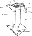
도 5는 축조 재료 용기의 다른 예의 사시도,
도 7a는 축조 재료 용기의 다른 예의 개략적인 측면도,
도 7b는 도 7a의 예시적인 축조 재료 용기의 개략적인 평면도,
도 7a는 상대적으로 편평한 구성의 예시적인 축조 재료 용기의 세트의 개략적인 측면도,
도 7b는 사용시 구성의 도 7a의 예시적인 축조 재료 용기의 세트의 개략적인 측면도,
도 8a는 상대적으로 편평한 구성의 다른 예시적인 축조 재료 용기의 사시도,
도 8b는 사용시 구성의 도 7a의 예시적인 축조 재료 용기의 부분 사시도,
도 8c는 예시적인 보강 구조체를 형성하도록 예시적인 피스의 재료의 사시도,
도 9는 다른 예시적인 축조 재료 용기의 사시도,
도 10a는 다른 예시적인 축조 재료 용기의 사시도,
도 10b는 도 9a의 예시적인 축조 재료 용기의 사시도,
도 11은 다른 예시적인 축조 재료 용기의 사시도,
도 12는 예시적인 3D 프린팅 시스템과 함께 사용하는 예시적인 축조 재료 용기의 개략도,
도 13은 용기로부터 3D 프린팅 시스템으로 축조 재료를 제공하기 위한 예시적인 방법의 흐름도,
도 14는 용기로부터 축조 재료를 제거하기 위한 예시적인 방법의 흐름도.1 is a schematic side view of an example of a build-up material container,
2 is a schematic view of an example of a building material outer structure,
Figure 3a is a schematic side view of an example of a build-
Figure 3b is a schematic plan view of the exemplary build material container of Figure 3a,
Figure 4a is a schematic cross-sectional view through another example of a build-
Figure 4b is a schematic plan view of an exemplary build material container of Figure 4a,
Figure 4c is a schematic side view of the exemplary build material container of Figure 4a,
Figure 5 is a perspective view of another example of a build-
Figure 7a is a schematic side view of another example of a build-
Figure 7b is a schematic plan view of the exemplary build material container of Figure 7a,
Figure 7a is a schematic side view of an exemplary set of building material containers of a relatively flat configuration,
FIG. 7B is a schematic side view of a set of exemplary build material containers of FIG. 7A in use configuration,
8A is a perspective view of another exemplary build material container of a relatively flat configuration,
FIG. 8B is a partial perspective view of the exemplary build material container of FIG. 7A in use,
8C is a perspective view of the material of an exemplary piece to form an exemplary reinforcing structure,
9 is a perspective view of another exemplary build material container,
10A is a perspective view of another exemplary build material container,
Figure 10b is a perspective view of the exemplary build material container of Figure 9a,
11 is a perspective view of another exemplary build material container,
Figure 12 is a schematic view of an exemplary build material container for use with an exemplary 3D printing system;
Figure 13 is a flow diagram of an exemplary method for providing a build material from a vessel to a 3D printing system,
14 is a flow diagram of an exemplary method for removing building material from a vessel.
3차원 물체는 적층 가공 기술을 사용하여 생성될 수 있다. 이 물체는 축조 재료의 연속적인 층의 일부를 고화시킴으로써 생성될 수도 있다. 축조 재료는 분말을 기반으로 할 수 있고, 생성된 물체의 특성은 축조 재료의 유형 및 고화의 유형에 따라 달라질 수도 있다. 일부 예시에 있어서, 분말 재료의 고화는 액체 융제를 사용하여 가능하다. 다른 예시에 있어서, 고화는 축조 재료에 대한 에너지의 일시적인 인가에 의해 가능할 수도 있다. 특정 예시에 있어서, 융제 및/또는 결착제가 축조 재료에 도포되고, 융제는, 적합한 양의 에너지가 축조 재료 및 융제의 조합에 인가되는 경우, 축조 재료가 융합(fuse) 및 고화되게 하는 물질이다. 다른 예시에 있어서, 다른 축조 재료 및 다른 고화의 방법이 사용될 수도 있다. 특정 예시에 있어서, 축조 재료는 페이스트 재료, 슬러리 재료 또는 액체 재료를 포함한다. 본 개시는 축조 재료를 포함하고 이를 적층 가공 공정에 전달하기 위한 소스 용기의 예시를 설명한다.Three-dimensional objects can be created using stacking techniques. This object may be created by solidifying a part of the continuous layer of the building material. The building material may be powder based, and the properties of the resulting object may vary depending on the type of building material and the type of solidification. In some instances, solidification of the powder material is possible using a liquid flux. In another example, solidification may be possible by temporary application of energy to the building material. In a specific example, a flux and / or binder is applied to the build material, and the flux is a material that causes the build material to fuse and solidify when a suitable amount of energy is applied to the combination of build material and flux. In another example, other building materials and other methods of solidification may be used. In certain examples, the build material comprises a paste material, a slurry material or a liquid material. This disclosure describes an example of a source container for containing a build material and delivering it to a lamination process.
일례에 있어서, 본 개시의 용기 내의 축조 재료는, 대략 5 미크론 내지 대략 400 미크론, 대략 10 미크론 내지 대략 200 미크론, 대략 15 미크론 내지 대략 120 미크론, 또는 대략 20 미크론 내지 대략 70 미크론의 평균 용적-기반의 단면 입자 직경 크기를 갖는 분말이다. 적합한 평균 용적-기반의 입자 직경 범위의 다른 예는 대략 5 미크론 내지 대략 70 미크론, 또는 대략 5 미크론 내지 대략 35 미크론을 포함한다. 본 개시에 있어서, 용적-기반의 입자 크기는 분말 입자와 동일한 용적을 갖는 구체의 크기이다. "평균(average)"에 대해서, 용기 내의 용적-기반의 입자 크기의 대부분은 언급된 크기 또는 크기 범위를 갖지만, 용기는 또한 언급된 범위 밖의 직경의 입자를 포함할 수도 있다는 것을 설명하는 것을 의미한다. 예를 들어, 입자 크기는 대략 10 미크론 내지 대략 500 미크론, 또는 대략 10 미크론 내지 대략 200 미크론, 또는 대략 15 미크론 내지 대략 150 미크론의 두께를 갖는 축조 재료 층을 분배시키는 것을 용이하게 하도록 선택될 수도 있다. 적층 가공 시스템의 일례는, 대략 40 미크론 내지 대략 70 미크론의 평균 용적-기반의 입자 직경을 갖는 분말을 포함하는 축조 재료 용기를 사용하여, 대략 80 미크론의 축조 재료 층을 분배하도록 사전-설정될 수도 있다. 예를 들어, 적층 가공 장비는 상이한 층 두께를 분배하도록 재설정될 수 있다.In one example, the build material in the container of the present disclosure may have a mean volume-based (e.g., from about 5 microns to about 400 microns, from about 10 microns to about 200 microns, from about 15 microns to about 120 microns, or from about 20 microns to about 70 microns Sectional particle size of the powder. Other examples of suitable average volume-based particle diameter ranges include about 5 microns to about 70 microns, or about 5 microns to about 35 microns. In this disclosure, the volume-based particle size is the size of a sphere having the same volume as the powder particle. For "average ", it is meant to describe that most of the volume-based particle size in the vessel has a size or size range mentioned, but that the vessel may also include particles of diameter outside the stated range . For example, the particle size may be selected to facilitate dispensing a layer of build material having a thickness of from about 10 microns to about 500 microns, or from about 10 microns to about 200 microns, or from about 15 microns to about 150 microns . An example of a stack processing system may be pre-set to dispense a layer of build material of approximately 80 microns using a build material container that includes a powder having a mean volume-based particle diameter of approximately 40 microns to approximately 70 microns have. For example, the stack processing equipment can be reset to dispense different layer thicknesses.
본 개시의 예시적인 용기 내에서 사용하기 위한 적합한 분말-기반의 축조 재료는 폴리머, 결정질 플라스틱(crystalline plastic), 반결정질 플라스틱, 폴리에틸렌(polyethylene; PE), 폴리락트산(polylactic acid; PLA), 아크릴로나이트릴 부타디엔 스티렌(acrylonitrile butadiene styrene; ABS), 아모퍼스 플라스틱(amorphous plastic), 폴리비닐 알코올 플라스틱(polyvinyl alcohol plastic; PVA), 폴리아미드, 열가소성(열경화성) 플라스틱, 수지, 투과성 분말, 색 분말, 금속 분말, 예를 들면, 유리 입자와 같은 세라믹 분말, 및/또는 이들 또는 다른 재료 중 적어도 2개의 조합물 중 적어도 하나를 포함하고, 이러한 조합물은 상이한 입자, 각각의 상이한 재료, 또는 단일 화합물 입자의 상이한 재료를 포함할 수도 있다. 혼합된 축조 재료의 예는 알루미늄 및 폴리아미드의 혼합물을 포함할 수도 있는 알루마이드, 다색 분말, 및 플라스틱/세라믹 혼합물을 포함한다. 혼합된 축조 재료는 2개 이상의 상이한 각자의 평균 입자 크기를 포함할 수도 있다.Suitable powder-based building materials for use in the exemplary containers of this disclosure include, but are not limited to, polymers, crystalline plastic, semicrystalline plastic, polyethylene (PE), polylactic acid Acrylonitrile butadiene styrene (ABS), amorphous plastic, polyvinyl alcohol plastic (PVA), polyamide, thermoplastic (thermosetting) plastic, resin, permeable powder, color powder, metal At least one of a powder, a ceramic powder, such as, for example, glass particles, and / or a combination of at least two of these or other materials, the combination comprising different particles, But may also include different materials. Examples of blended building materials include alumides, multicolor powders, and plastic / ceramic blends which may include mixtures of aluminum and polyamides. The mixed build material may include an average particle size of two or more different ones.
적층 가공 공정 내에 사용된 축조 재료의 특정한 군(batch)은 "버진(virgin)" 축조 재료 또는 "사용된" 축조 재료일 수도 있다. 버진 축조 재료는 적층 가공 공정의 임의의 부분에서 사용되지 않았거나, 및/또는 이전에 3D 프린팅 시스템의 임의의 부분을 통과하지 않은 축조 재료로 고려되어야 한다. 그러므로, 축조 재료 제조자에 의해 제공되는 바와 같은 축조 재료의 개봉하지 않은(unopened) 공급원은 버진 축조 재료를 포함한다. 이에 반해, 사용된 축조 재료는 적층 가공 공정에서 사용되기 위해 3D 프린팅 시스템에 이미 제공되었다. 적층 가공 공정에서 사용되기 위해 3D 프린팅 시스템에 제공된 축조 재료 전부가 사용되거나, 및/또는 3D 프린팅된 물건(article)에 통합될 수 있는 것은 아니다. 적층 가공 공정에서 사용되기 위해 3D 프린팅 시스템에 제공된 사용되지 않은 축조 재료 중 적어도 일부는 차후의 적층 가공 공정에서 재사용되기에 적합할 수도 있다. 이러한 축조 재료는 사용된 축조 재료를 포함한다.A particular batch of build material used in the lamination process may be a "virgin" build material or a "used" build material. The virgin construction material should be considered as a building material that has not been used in any part of the lamination process and / or has not passed through any part of the 3D printing system before. Therefore, the unopened source of the build material as provided by the build material manufacturer includes the virgin build material. In contrast, the used construction materials have already been provided in 3D printing systems for use in the lamination process. Not all of the building materials provided in the 3D printing system for use in the lamination process may be used and / or incorporated into 3D printed articles. At least some of the unused build material provided in the 3D printing system for use in the lamination process may be suitable for re-use in subsequent lamination processes. Such a building material includes the used building material.
본 개시의 일부 예시적인 용기는, 본 명세서에 설명된 용기의 다른 예와 비교하여, 축조 재료의 상대적으로 큰 용적을 포함하기에 적합할 수도 있다. 일부 예시적인 용기는, 용기가 용이하게 적층, 저장, 이송, 배치 또는 재충전(refill)될 수 있다는 것을 보장하는 특징부를 포함할 수도 있다. 충전된 조건에서, 이러한 예시적인 용기는 상대적으로 큰 용적의 축조 재료를 포함해야 한다. 본 개시의 일부 예시적인 용기는 비충전 상태에서 용기의 이송을 용이하게 하도록 구성될 수도 있다. 일부 예시적인 용기는 적층 가공 공정에서 사용되기 위해 3D 프린팅 시스템에 이미 제공되었던 사용된 축조 재료를 수용 및 저장하기 위해 사용하기에 적합하고, 3D 프린팅 시스템에 버진 축조 재료를 제공하기 위해 사용하기에 적합하도록 추가적으로 또는 대안적으로 회수될 수도 있다. 본 개시의 일부 예시적인 용기는 예를 들면, 3D 프린팅 시스템의 축조 재료 제공 시스템에 의한, 이러한 용기 내에 포함된 축조 재료의 효율적인 제거를 용이하게 할 수도 있다. 일부 이러한 예시적인 용기는 예를 들면, 축조 재료의 대부분 또는 전부는 용기로부터 제거될 수 있다는 것을 보장하는 특징부를 포함할 수도 있다. 이러한 예시적인 용기는 예를 들면, 축조 재료가 용기의 내부면에 부착되거나 그렇지 않으면, 축조 재료 제공 시스템에 접근하기 어렵기 때문에 축조 재료 제공 시스템에 의해 용기로부터 제거될 수 없는 축조 재료의 양을 감소시키는 특징부를 포함할 수도 있다.Some exemplary containers of the present disclosure may be adapted to include a relatively large volume of build material as compared to other examples of containers described herein. Some exemplary containers may include features that ensure that the container can be easily stacked, stored, transported, placed, or refilled. In the filled condition, this exemplary container should contain a relatively large volume of building material. Some exemplary containers of the present disclosure may be configured to facilitate transport of the containers in the unfilled state. Some exemplary containers are suitable for use to receive and store used construction materials that have already been provided in 3D printing systems for use in a lamination process and are suitable for use in providing virgin constructions to 3D printing systems Or alternatively may be recovered. Some exemplary containers of the present disclosure may facilitate efficient removal of the build material contained in such a container, for example, by a built-in material supply system of a 3D printing system. Some such exemplary containers may, for example, include features that ensure that most or all of the build material can be removed from the container. This exemplary container reduces the amount of build material that can not be removed from the vessel by the build-up material supply system because, for example, the build material is attached to the inner surface of the vessel or otherwise difficult to access the build- And the like.
도 1 내지 도 5b를 참조하여 이하에 설명된 예시적인 용기는, 이러한 용기로부터의 축조 재료의 효율적인 제거를 용이하게 하는 하나 이상의 특징부를 포함한다.The exemplary container described below with reference to Figs. 1 to 5B includes one or more features that facilitate the efficient removal of the build material from such a container.
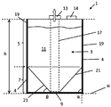
도 1은 적층 가공 공정에 축조 재료(11)를 제공하기 위한 용기(1)의 일례의 개략적인 정면도를 도시한다. 용기(1)는 이 용기의 의도된 사용시 배향에 대응하는 수직 배향으로 도시된다. 용기(1)는, 적층 가공 시스템이 용기(1)로부터 축조 재료를 수집할 수 있도록 적어도 부분적으로 충전된 조건에서 적층 가공 시스템에 연결되어야 하고, 축조 재료로 충전된 제 2, 유사한 용기로 교체가능하게 되기 위해 고갈 후에 제거되어야 하는 교체가능한 소스 용기(1)일 수도 있다. 그러므로, 용기는 3D 프린팅 축조 재료 용기가 되도록 고려될 수도 있다. 일례에 있어서, 축조 재료는 예를 들면, 상술된 바와 같은 유형 및/또는 입자 크기의 분말이다.Fig. 1 shows a schematic front view of an example of a
용기(1)는 축조 재료(11)를 보유하도록 압괴가능한(collapsible) 저장소(3)를 포함한다. 용기(1)는 이 저장소의 적어도 하나의 보강부의 압괴(collapsing)에 저항하는 상대적으로 강성의 보강 구조체를 더 포함한다. 용기(1)는 축조 재료(11)가 저장소(3)를 빠져나가게 하는 축조 재료 출구 구조체(13)와, 가스(예를 들면, 공기)가 저장소(3)로 들어가게 하는 가스 입구 구조체(14)를 더 포함한다.The container (1) comprises a collapsible reservoir (3) to hold the build material (11). The
저장소(3)는 예를 들면, 플라스틱 재료의 하나 또는 여러 부분으로 형성된, 백(bag)을 포함할 수도 있다. 저장소(3)는 하나 또는 여러 벽을 포함할 수도 있다. 축조 재료(11)는 저장소(3)의 벽에 의해 둘러싸일 수도 있다. 저장소(3)는 보강 구조체(4)에 대해 압괴가능하다. 저장소(3)는 용기(1)의 사용 동안에 적어도 부분적으로 압괴되도록 의도된다. 본 개시의 내용에서, 구조체의 압괴는 그 구조체에 의해 밀폐되거나 차지되는 용적의 감소를 수반하는 것으로 고려될 수도 있다. 저장소(3)는 적어도 부분적으로 가요성 재료로 형성될 수도 있다. 일부 예에 있어서, 저장소(3)는 상대적으로 가요성이다. 일례에 있어서, (재료에 관한) 상대적으로 가요성은 재료의 굽힘(bending) 및/또는 휨(flexing)을 허용하는 것으로 이해될 수 있다. 가요성 재료 또는 화합물은 탄성(예를 들면, PE) 또는 비-탄성[예를 들면, 마일러(Mylar)]일 수 있다. 일례에 있어서, 가요성 및 탄성 재료는 대략 1*109N/㎡㎬ 미만, 또는 대략 0.3*109N/㎡㎬ 미만의 영률을 갖는다. 일례에 있어서, 상대적으로 강성 또는 비-탄성의 벽 재료는 대략 1*109N/㎡㎬ 초과의 영률을 갖는다.The
저장소(3)를 형성하는 재료는 예를 들면, 재료가 용기(1)를 사용하도록 의도되는 특정 방식에 따라 선택된, 사전선택된 탄성을 가질 수도 있다. 흡인(aspiration) 시스템을 사용하여 용기(2)로부터 축조 재료(11)를 제거하도록 의도되는 예시에 있어서, 저장소 재료는 저탄성(예를 들면, 저장소 재료의 신장이 흡인 시스템의 작동 동안에 거의 발생하지 않을 정도로 충분히 낮음)과, 고 인장 강도(예를 들면, 25㎫)를 가질 수도 있다. 저장소(3)를 형성하는 재료는 밀폐(즉, 용기로부터 축조 재료를 제거하도록 흡인 시스템에 의해 사용될 수도 있는 공기 또는 임의의 다른 가스가 저장소(3)의 벽을 통과할 수 없도록, 가스 불침투성)될 수도 있다. 일부 예에 있어서, 저장소(3)는 적어도 부분적으로, PE, 박막 PET(thin-walled PET), 마일러 등과 같은 플라스틱 재료로 형성된다. 일부 예시에 있어서, 저장소는 하나 또는 여러 재료(예를 들면, PET 및 LDPE)의 합판(laminate)으로 형성된다. 일부 예시에 있어서, 저장소 재료는 탄성(예를 들면, 충전된 상태에서 떨어뜨릴 경우 파괴되지 않도록 충분한 탄성)이고, 환경으로부터 수분을 흡수하지 않으며, 예를 들면, 흡입력이 저장소(3)로부터 축조 재료를 제거하도록 인가될 때, 재료가 선택된 양 이상만큼 변형되지 않도록 충분히 강성이다. 저장소(3)는 저가의, 1회용의, 및/또는 재활용가능한 재료로 형성될 수 있다.The material forming the
저장소(3)의 재료 특성(예를 들면, 가요성, 탄성 등)은, 용기(1)로부터 축조 재료를 제거하기 위한 시스템(예를 들면, 흡인 시스템)이 작동될 때 저장소가 부분적으로 압괴된 형태를 채용하도록, 선택될 수도 있다. 예를 들어, 소정의 저장소의 저장소 재료는 그 저장소로부터 축조 재료(11)를 제거하는데 사용되도록 의도된 축조 재료 제거 시스템에 의해 인가된 흡입력에 의해 압괴가능하게 되기에 충분히 가요성일 수도 있다. 저장소(3)의 재료 특성은, 임계량의 축조 재료(11)가 이 저장소(3) 내에 남아 있을 때, 용기로부터의 축조 재료의 제거 동안에, 저장소가 부분적으로 압괴된 형태를 채용하도록 선택될 수도 있다. 저장소는 (예를 들면, 재료 특성, 형상, 구성 등의 결과로서) 저장소(3)의 내측 및 외측 사이의 임계 차압이 도달될 때, 용기(1)로부터의 축조 재료의 제거 동안에, 부분적으로 압괴된 형태를 채택하도록 구성될 수도 있다. 일부 예시에 있어서, 저장소(3)의 재료 특성은, 용기(1)로부터의 축조 재료(11)의 제거 동안에, 비-압괴 형태와 부분적으로 압괴된 형태 사이에서 점진적으로 전환(transition)되도록 선택된다. 일부 예시에 있어서, 저장소(3)의 재료 특성은, 용기(1)로부터의 축조 재료(11)의 제거 동안에, 비-압괴 형태와 부분적으로 압괴된 형태 사이에서 신속하게 또는 순간적으로 전환되도록 선택된다. 부분적으로 압괴된 형태에 대한 이러한 신속한 또는 순간적인 전환은 저장소 벽의 내측면에 느슨하게 부착된 임의의 축조 재료(11)의 제거 및 또는 축조 재료(11) 내에 형성되었던 임의의 구조체의 파괴(break up)를 용이하게 할 수도 있다.The material properties (e.g., flexibility, resilience, etc.) of the
저장소(3)는 예를 들면, 용기(1)의 특정한 의도된 사용에 따라 선택된 사전선택된 형상을 가질 수도 있다. 예를 들어, 특정한 의도된 사용이 용기(1)에 크기 및/또는 구성 제약을 두는 경우, 저장소(3)의 형상은 이러한 제약 내에서 저장소(3)의 내부 용적을 최대화하도록 선택될 수도 있다. 저장소(3)의 형상은 특정한 제거 시스템을 사용하여 저장소(3)로부터 축조 재료(11)의 제거를 용이하게 하도록 선택될 수도 있다. 저장소(3)의 형상은, 예를 들면, 저장소가 용기(1) 내에 통합되기 전에, 실질적으로 편평한 절첩 상태로 이송될 수 있도록, 저장소의 절첩을 용이하게 하도록 선택될 수도 있다. 저장소(3)는 [적어도 저장소(3)의 충전되었지만 압괴되지 않은 상태에서] 일반적인 형상으로 서로 상이한 섹션, 예를 들면, 수렴 섹션 및 비-수렴 섹션을 포함할 수도 있다. 수렴 섹션은 용기의 베이스를 향해 수렴하는 측벽을 포함할 수도 있다. 도 1에 도시된 저장소(3)는 예를 들면, 비-수렴 상부 섹션(5) 및 수렴 하부 섹션(7)을 포함한다. 저장소는 깔때기(funnel) 형상을 갖는 섹션을 포함할 수도 있다. 비-수렴 섹션은 적어도 저장소의 충전되고 비-압괴된 상태에서, (사용시 배향에 대해) 실질적으로 수직으로 연장되는 적어도 하나의 측벽을 포함할 수도 있다. 적어도 하나의 실질적으로 수직의 측벽은 적어도 하나의 원형 벽일 수도 있거나, 평면도(도시되지 않음)로부터 보이는 바와 같이, 직선 또는 원형 코너를 갖는 직사각형을 형성할 수도 있다. 도 1에 도시된 특정한 도시된 예시적인 저장소(3)는 4개의 실질적으로 수직의 측벽(19)에 의해 형성된 상부 섹션(5)과, 4개의 수렴하는 측벽(21)에 의해 형성된 하부 섹션(7)을 구비한다. 상부 섹션(5)은 입방형이고, 하부 섹션(7)은 피라미드형이다. 측벽(19, 21)은 플라스틱 재료의 일부를 각각 포함하고, 밀폐 백 구조체를 형성하도록 그들의 에지에서 밀봉적으로 접합된다.The
용기(1)의 사용시 배향의 실질적으로 수직이 되도록 의도되는 비-수렴 저장소 섹션의 측벽[예를 들면, 측벽(19)]은 예를 들면, 가공 허용오차, 몰드 방출 각도, 저장소의 열적 경화, 또는 다른 이유 때문에, 완벽하게 수직이 아닐 수도 있다. 예를 들어, 적어도 하나의 실질적으로 수직의 측벽(19)은 예를 들면, 수평(H)으로부터 대략 85도 내지 95도의 각도(α) 하에서 약간 경사질 수도 있거나, (외측 또는 내측으로) 약간 팽출한 형상을 가질 수도 있다. 수평(H)과 비교적 수직인 측벽(19) 사이의 각도(α)는 하부 섹션(7)의 측벽(21)과 수평(H) 사이의 각도(β)보다 크다. 또한, 예시에 따른 저장소가 압괴가능하기 때문에, 저장소의 실질적으로 수직의 측벽은 용기(1)의 조건에 따라 직선 또는 수직이 아닐 수도 있다. 예를 들어, 예시적인 저장소(3)는 비어있는 조건일 때 절첩되어야 하고, 측벽(19, 21)은 저장소(3)로부터 축조 재료의 제거 동안에 구부러져야 한다.The sidewall (e.g., sidewall 19) of the non-converging reservoir section intended to be substantially perpendicular to the orientation of the orientation of use of the
게다가, 저장소 벽은 주름부, 만곡부, 릿지, 파형부 등을 포함할 수도 있다. 일부 예시에 있어서, 저장소(3)의 적어도 하나의 측벽은 보강 구조체(4)의 대응하는 측벽보다 적어도 한 치수 클 수도 있다. 저장소 재료의 탄성이 낮은 예시에 있어서, 이러한 특징은 저장소(3)의 적어도 하나의 측벽이 보강 구조체(4)에 대해 이동 가능하게 할 수 있다. 이러한 예시에 있어서, 용기(1)의 충전된 상태에서, 적어도 하나의 측벽의 보다 큰 크기가 예를 들면, 저장소(3)의 적어도 하나의 측벽의 주름부, 릿지 또는 다른 비-편평 특징부의 형성에 의해 수용될 수도 있다는 것이 이해될 것이다.In addition, the reservoir wall may include corrugations, curves, ridges, corrugations, and the like. In some examples, at least one side wall of the
저장소의 적어도 하나의 보강부는 저장소의 적어도 하나의 벽부를 포함할 수도 있다. 적어도 하나의 보강부의 하나 또는 여러 속성(예를 들면, 크기, 형상, 위치)이 사전선택될 수도 있다. 적어도 하나의 보강부는, 저장소(3) 내에서의 압력이 저장소(3)를 압괴시키기 위해 저장소(3)의 외측의 압력보다 충분히 낮을 때, 저장소는 부분적으로 압괴된 형태를 채택하도록 될 수도 있다. 일부 예시에 있어서, 부분적으로 압괴된 형태는 사전결정된다. 예를 들어, 부분적으로 압괴된 형태의 하나 또는 여러 속성(예를 들면, 크기, 구성, 용적)은 사전결정된다. 일부 예시에 있어서, 서전결정된 부분적으로 압괴된 형태는 저장소 내에 포함된 축조 재료를 저장소 내에서의 선택된 위치로 안내하는 것이다. 위치는 예를 들면, 용기(1)로부터 축조 재료를 제거하는데 사용되는 축조 재료 제거 시스템의 구성에 기반하여 선택될 수도 있다. 일부 예시에 있어서, 용기가 의도된 사용시 배향으로 있을 때 사전결정된 부분적으로 압괴된 형태의 최하점은 일반적으로 축조 재료를 3D 프린팅 시스템에 제공하도록 용기의 사용 동안에 저장소로부터 제거되어야 하는 위치에 대응한다. 사전결정된 부분적으로 압괴된 형태는, 적어도 하나의 보강부의 하나 이상의 속성을 선택하는 것에 의해, 저장소(3)의 형상 및/또는 구성을 선택하는 것에 의해, 보강 구조체(4)의 형상 및/또는 구성을 선택하는 것에 의해, 및/또는 저장소(3)의 하나 또는 여러 재료 특성을 선택하는 것에 의해 생성될 수도 있다.The at least one reinforcement of the reservoir may comprise at least one wall of the reservoir. One or more attributes (e.g., size, shape, location) of at least one reinforcement may be preselected. The at least one reinforcing portion may be adapted to adopt a partially collapsed configuration when the pressure in the
보강 구조체(4)는 저장소(3)의 적어도 하나의 보강부의 압괴에 저항하기에 적합한 임의의 구조체를 포함할 수도 있다. 용기(1)가 보강 구조체(4)보다 강성인 다른 구성요소를 포함할 수도 있더라도), 보강 구조체(4)는 저장소(3)에 비해 강성이다. 강성 재료는 압괴에 저항할 수 있는 것으로 이해되어야 하고, 또한 굽힘 및/또는 신장 또는 변형의 임의의 다른 형태에 저항할 수도 있다. 보강 구조체(4)는 용기(1)의 사용 동안에 압괴되도록 의도되지 않으므로, [용기(1)의 사용 동안에 보강 구조체에 의해 경험되도록 예상되는 것보다 상당히 큰 외력을 인가하는 것에 의해 보강 구조체를 압괴가능할 수도 있다는 것이 인식되더라도] 압괴가능하지 않은 것으로 고려될 수도 있다. 일부 예시에 있어서, 보강 구조체(4)는 이 보강 구조체에 대한 저장소(3)의 적어도 하나의 보강부의 이동을 방지 또는 제한한다.The
보강 구조체(4)는 (예를 들면, 글루, 파스너 등을 사용하여) 적어도 하나의 보강부에 부착되는 것에 의해 저장소(3)의 적어도 하나의 보강부의 압괴에 저항할 수도 있다. 일부 예시에 있어서, 저장소는 비-수렴 상부 섹션(5) 및 수렴 하부 섹션(7)을 포함하고, 상부 섹션(5)은 적어도 하나의 보강부를 형성한다. 일부 이러한 예시에 있어서, 상부 섹션은 대체로 정사각형 또는 직사각형 단면을 갖는 저장소(3)의 구역을 함께 형성하는 2개의 쌍의 대향하는 실질적으로 수직의 측벽을 포함하고, 적어도 하나의 보강부는 저장소가 부착되는 2개의 쌍의 대향 측벽 중 제 1 쌍을 포함하고, 그에 따라 제 1 쌍의 대향 측벽의 압괴는 보강 구조체(4)에 의해 저항되고, 저장소가 부착되지 않은 2개의 쌍의 대향 측벽 중 제 2 쌍의 대향 측벽의 압괴는 보강 구조체(4)에 의해 저항되지 않거나, 보다 작은 범위로 저항된다. 일부 예시에 있어서, 저장소(3)는 (의도된 사용시 배향에 대해서) 실질적으로 수직의 장축을 갖는 실린더를 포함하고, 적어도 하나의 보강부는 실린더의 상부 범위와 하부 범위 사이에 이격될 수도 있는 실린더의 둘레부(circumference)를 포함한다.The
일부 예시에 있어서, 보강 구조체(4)는 저장소(3)의 일부 또는 전부를 둘러싸는 용기의 박스 또는 다른 형태를 포함한다. 보강 구조체(4)는 적어도 하나의 측벽을 포함할 수도 있다. 다른 예시에 있어서, 보강 구조체(4)는 프레임 또는 스켈레톤(skeleton)을 포함할 수도 있다. 일부 예시에 있어서, 보강 구조체(4)는 하나의 밴드 또는 링, 또는 하나 이상의 밴드 또는 링을 포함할 수도 있다. 보강 구조체(4)는 저장소(3)의 내부 공간 내에서, 저장소(3)의 외부에 제공될 수도 있거나, 저장소(3)의 구조 내에 통합될 수도 있다[예를 들면, 보강 구조체(4)는 저장소(3)의 적층된 벽 재료의 층들 사이에 제공될 수 있음]. 일부 예시에 있어서, 보강 구조체(4)는 저장소의 사전선택된 벽 부분의 휨에 저항하는 것에 더하여, 하나 또는 여러 기능을 제공하도록 할 수도 있다. 예를 들어, 보강 구조체(4)는 저장소(3)를 보호하고, 용기(1)의 적층을 용이하게 하고, 용기(1)의 취급을 용이하게 하고, 용기(1)의 외부 프로파일을 생성하는 등을 할 수도 있다. 보강 구조체(4)는 판지(cardboard)와 같은 저가의, 1회용의, 및/또는 재활용가능한 재료로 형성될 수도 있다. 보강 구조체(4)의 형상 및/또는 구성은 예를 들면, 보강 구조체(4)가 용기(1) 내에 통합되기 전에, 실질적으로 편평한 절첩된[예를 들면, 플랫 팩(flat packed)] 상태로 이송될 수 있도록, 보강 구조체의 절첩을 용이하게 할 수도 있다. 보강 구조체(4)의 형상 및/또는 구성은 예를 들면, 용기(1)가 축조 재료로 충전되기 전에, 실질적으로 편평한 절첩 상태로 이송될 수 있도록, 용기(1)의 절첩을 용이하게 할 수도 있다.In some examples, the reinforcing
보강 구조체(4)는 예를 들면, 용기(1)의 특정한 의도된 사용에 따라 결정된 사전결정된 형상 및 또는 구성을 가질 수도 있다. 일부 예시에 있어서, 보강 구조체의 형상 및/또는 구성은 저장소(3)의 형상 및/또는 구성에 의존하여 결정된다. 보강 구조체(4)의 형상 및/또는 구성은, 저장소(3) 내의 압력이 저장소(3)를 압괴하도록 저장소의 외측의 압력보다 충분히 낮을 때, 저장소(3)가 사전결정된 부분적으로 압괴된 형태를 채택하게 할 수 있도록, 저장소(3)의 형상 및/또는 구성과 협동하도록 결정될 수도 있다.The reinforcing
사전결정된 부분적으로 압괴된 형태는 저장소(3) 내에 포함된 축조 재료를, 저장소 내에서의 사전선택된 위치(예를 들면, 축조 재료가 흡인 시스템과 같은 축조 재료 제거 시스템에 의해 제거될 수 있는 위치)로 안내하도록 구성될 수도 있다. 일부 예시에 있어서, 사전결정된 부분적으로 압괴된 형태는, 축조 재료를 3D 프린팅 시스템에 제공하기 위해 용기의 사용 동안에, 축조 재료가 저장소로부터 제거될 수 있는 위치에 대응하는 (용기가 의도된 사용시 배향으로 있을 때의) 최하점을 갖는다. 일부 예시에 있어서, 사전결정된 부분적으로 압괴된 형태는, 저장소(3)의 벽이 축조 재료를 가둘 수 있는 임의의 형성물(formation)(예를 들면, 절첩부 또는 포켓)을 포함하지 않도록 한다. 게다가, 또는 대안적으로, 일부 예시에 있어서, 사전결정된 부분적으로 압괴된 형태는 저장소(3)의 하부 부분(7)의 벽이 임의의 수평 특징부 또는 구역을 포함하지 않도록 한다. 부분적으로 압괴된 형태를 갖는 저장소의 용적은 압괴되지 않을 때(예를 들면, 저장소가 상당히 용적을 변화시키는 일 없이 변형될 수도 있음), 저장소의 용적과 실질적으로 동일할 수도 있다. 대안적으로, 부분적으로 압괴된 형태를 갖는 저장소의 용적은 압괴되지 않을 때의 저장소의 용적의 적어도 80%일 수도 있다.The pre-determined, partially collapsed form allows the build material contained in the
일정 기간 동안 용기(1) 내에서 영향을 받지 않고 안착되어 있는 축조 재료(11)는 컴팩트하고, 및/또는 용기(1)로부터 축조 재료의 제거가 소망될 때 축조 재료가 자유롭게 이동하는 것을 방지하는 구조체를 형성할 수도 있다. 흡인 시스템에 의해 생성된 흡입력과 같은 축조 재료 제거 시스템에 의해 인가된 힘은 이러한 구조체를 파괴하는데 효과적이지 않아서, 용기(1)로부터 축조 재료의 불완전한 제거로 이어질 수도 있다. 압괴되지 않은 형태에서 부분적으로 압괴된 형태로의 저장소(3)의 전환은 축조 재료 내의 구조를 파괴하는 것을 용이하게 할 수도 있다. 사전결정된 부분적으로 압괴된 형태는 축조 재료 내의 구조의 이러한 압괴를 용이하게 하도록 채택될 수도 있다.The build-up
도 1의 도시된 예시에 있어서, 보강 구조체(4)는 4개의 실질적으로 수직의 측벽 및 실질적으로 수평의 베이스를 구비하는 오픈-탑 박스(open-topped box)를 포함한다. 보강 구조체(4)의 측벽은 저장소(3)의 상부 섹션(5)의 측벽(19)의 외부면에 인접하는 동시에, 저장소의 하부 섹션(7)의 측벽(21)과 보강 구조체 측벽 사이에 [하부 섹션(7)의 수렴 형상에 의해] 공간이 존재한다. 보강 구조체(4)의 높이는 [보강 구조체가 저장소(3)보다 더 높거나 더 낮은 다른 예시가 가능하더라도] 저장소(3)의 높이와 대략 동일하다. 보강 구조체(4)의 형상 및 구성은, 저장소(3)의 상부 섹션(5)의 측벽(19)과 보강 구조체(4)의 측벽 사이에 갭(gap)이 거의 없도록, (적어도 저장소가 충전 상태에 있을 때) 저장소(3)의 상부 섹션의 형상 및 구성과 일치한다.In the illustrated example of FIG. 1, the
저장소(3)의 상부 섹션(5)의 대향 쌍의 측벽(19)은 보강 구조체(4)의 대응하는 측벽에 글루 접착(glue)되고, 이에 의해 보강 구조체(4)에 대해 이동되는 것이 방지된다. 저장소(3)의 상부 섹션(5)의 다른 2개의 측벽(19)은 보강 구조체(4)에 부착되지 않고, 보강 구조체(4)에 대한 [보강 구조체(4)에 부착되는 측벽에 대한 그들의 연결에 의해 강요된 제약 내에서의] 이동이 자유롭다. 그러므로, 비-부착된 측벽은 이동이 비교적 자유롭도록 고려될 수도 있다(즉, 이 측벽은 이동이 자유롭지 않은 부착된 측벽에 비해 이동이 자유로움). 용기(1)를 둘러싸는 가스는 저장소(3)의 적어도 일부 부분과 보강 구조체(4) 사이, 예를 들면, 비-부착된 상부 섹션 측벽(19)과 보강 구조체(4)의 대응하는 측벽 사이, 및 하부 섹션 측벽(21)과 보강 구조체(4)의 측벽 사이를 통과할 수 있다. 저장소(3)의 하부 섹션(7)의 베이스부(9)는 보강 구조체(4)의 베이스에 고정되고, 이에 의해 보강 구조체(4)에 대해 이동하는 것이 방지된다. 나타낸 예시에 있어서, 저장소(3)의 하부 섹션(7)의 측벽(21)은 보강 구조체(4)에 부착되지 않고, 보강 구조체(4)에 대해 이동이 (비교적) 자유롭다.The opposite pair of
용기(1)의 출구 구조체(13)는 저장소(3)의 내부 공간을 저장소(3)의 외부의 공간에 연결하는 개구부를 포함할 수도 있다. 출구 구조체(13)의 초기 기능이 축조 재료가 저장소(3)를 빠져나가게 하는 것이더라도, 일부 예시에 있어서, 출구 구조체(13)는 또한, 축조 재료가 저장소(3) 내로 통과되게 할 수도 있다. 도 1에 도시된 예시에 있어서, 출구 구조체(13)는 용기(1)의 천장 측부(15) 내에 또는 근처에 제공된다. 출구 구조체(13)는 용기(1)로부터 축조 재료를 수집하는 대응하는 수집 장비에 연결되도록 채택될 수도 있다. 이러한 수집 장비는 적층 가공 시스템의 일부일 수도 있다. 도 1에 도시된 특정 예시에 있어서, 출구 구조체는 저장소(3)의 내부 공간 내에서, 저장소(3)의 최하극부에 또는 최하극부 근처의 지점으로 하향으로 연장되는 흡인 튜브(17)를 포함한다. 출구 구조체(13)는 폐쇄된 구성에 있을 때 축조 재료가 이 구조체를 통과하는 것을 제한 또는 방지하거나, 개방된 구성에 있을 때 축조 재료가 이 구조체를 통과하는 것을 허용하도록, 실제 밸브 구성체를 포함할 수도 있다.The
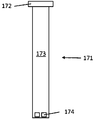
도 2는 흡인 튜브(171)의 형태의 출구 구조체의 특정 예시를 도시한다. 흡인 튜브(171)는 축조 재료 용기[예를 들면, 용기(1)]의 저장소[예를 들면, 저장소(3)]의 천장 부분에 기밀하게 부착되도록 커넥터(172)를 포함한다. 또한, 커넥터(172)는 진공 소스, 예를 들면, 적층 가공 시스템의 흡인 시스템에 연결가능하다. 흡인 튜브(317)는 바디 섹션(173)을 더 포함한다. (도 2에 도시된 바와 같이, 흡인 튜브의 의도된 사용시 배향에 대해 규정된 바와 같은) 바디 섹션(173)의 상단부는 커넥터(172)에 연결된다. 바디 섹션(173)은 중공 실린더를 포함한다. 커넥터(173)에 의해 규정된 개구부는 바디 섹션(173)의 내부와 유체 연통할 수도 있다. 바디 섹션(173)의 하단부는 바디 섹션(173)의 내부 공간 내로의 적어도 하나의 개구부(174)를 포함한다. 바디 섹션(173)의 길이는 흡인 튜브가 사용 중일 때 적어도 하나의 개구부(174)가 저장소의 하극부에, 또는 하극부 근처에 위치되도록 될 수도 있다. 흡인 튜브가 진공 소스에 연결될 때, 저장소로부터의 축조 재료는 적어도 하나의 개구부(174)를 통해 바디 섹션(173)의 내부로 들어가고 바디 섹션(173)을 따라 상향으로 흡입될 수도 있고, 이에 의해 커넥터(172)를 거쳐서 용기를 빠져나갈 수도 있다. 일부 예시에 있어서, 흡인 튜브(171)는 이 흡인 튜브가 배치되는 용기의 저장소의 적어도 일부의 압괴에 저항하는 기능을 할 수도 있다. 일부 예시에 있어서, 흡인 튜브는 용기의 보강 구조체의 일부를 형성하도록 고려될 수도 있다. 대안적으로, 흡인 튜브(171)는 용기의 추가의 보강 구조체를 포함하도록 고려될 수도 있다.Fig. 2 shows a specific example of an exit structure in the form of a
입구 구조체(14)는 저장소(3)의 내부 공간을 저장소(3)의 외부의 공간에 연결하는 개구부를 포함할 수도 있다. 입구 구조체(14)의 초기 기능이 가스가 저장소(3)를 들어가게 하는 것이더라도, 일부 예시에 있어서, 입구 구조체(317)는 또한 가스가 저장소(3)를 빠져나가게 할 수도 있다. 도 1에 도시된 예시에 있어서, 입구 구조체(14)는 용기(1)의 천장 측부(15) 내에 또는 천장 측부(15) 근처에 제공된다. 입구 구조체(14)는 저장소(3)의 내부로의 및/또는 외부로의 가스의 유동의 파라미터(예를 들면, 유량 속도, 유량 용적)를 제한, 또는 그렇지 않으면 제어할 수도 있다. 일부 예시에 있어서, 입구 구조체(14)는 필터를 포함한다. 일부 예시에 있어서, 입구 구조체(14)는 밸브를 포함한다. 일부 예시에 있어서, 입구 구조체(14)는 축조 재료가 저장소(3) 내로 통과하게 할 수도 있다. 예를 들어, 축조 재료(11)는 적층 가공 시스템에 축조 재료를 제공하기 위해 용기(1)의 사용 전에, 입구 구조체(14)를 통해 저장소(3) 내로 도입될 수도 있고, 공기는 적층 가공 시스템에 축조 재료를 제공하기 위해 용기(1)의 사용 동안에 입구 구조체(14)를 통해 저장소(3)로 들어갈 수도 있다.The
도 3a 및 도 3b는 저장소(3) 내에서의 압력이 저장소(3)의 외측의 압력보다 충분히 낮고, 저장소가 이러한 차압의 결과로서 부분적으로 압괴되는 사용 시의 상태의 도 1의 예시적인 용기(1)를 도시한다. 도 3a는 용기(1)의 측면도이고, 도 3b는 용기(1)의 평면도이다. 차압은 예를 들면, 흡입력(F)을 제공하는 출구 구조체(13)에 연결된 진공 소스(도시되지 않음)에 의해 생성될 수도 있다. 보강 구조체(4)에 부착되지 않은 저장소(3)의 부분[예를 들면, 하부 부분(7)의 측벽(21) 및 상부 부분(5)의 측벽(19)]이 내측으로 휘어지고, 그에 따라 저장소(3)의 이러한 부분과 보강 구조체(4) 사이에 갭이 생성된다는 것을 도 3a 및 도 3b로부터 알 수 있다. 이에 반해, 보강 구조체(4)에 부착되는 저장소(3)의 부분[예를 들면, 상부 부분(5)의 측벽(19)]은 흡입력(F)의 영향 하에서 이동하는 것이 방지된다.Figures 3a and 3b show an
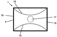
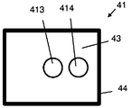
도 4a, 도 4b 및 도 4c는 추가의 예시적인 용기(41)를 도시한다. 도 4b는 용기(41)의 평면도이고, 도 4c는 측면도이며, 도 4a는 도 4b에 표시된 X-X선을 통한 단면도이다. 용기(41)는 상술된 용기(1)의 대응하는 구조체의 임의의 또는 모든 특징부를 가질 수도 있는 저장소(43), 보강 구조체(44), 출구 구조체(413) 및 입구 구조체(414)를 포함한다. 특정한 도시된 예시적인 용기(41)에 있어서, 보강 구조체(44)는 복수의 상대적으로 강성의 바 섹션으로 형성된 입방형 프레임을 포함한다. 특정 예시에 있어서, 보강 구조체(44)는 (예를 들면, 저장소 재료의 층들 사이에 바 섹션을 배치하는 것에 의해) 저장소(43)의 재료와 일체로 형성된다. 그러므로, 바 섹션을 포함하는 저장소의 일부는 저장소(43)의 일부를 보강하도록 고려될 수도 있다. 다른 예시에 있어서, 프레임은 저장소(43)에 내부적으로 또는 외부적으로 배치될 수도 있고, 저장소 재료는 예를 들면, 글루, 파스너 등에 의해 프레임에 부착될 수도 있다. 충전된 (그러므로, 압괴되지 않은) 상태에서의 저장소의 형상은 실선(43b)에 의해 나타나고, 저장소가 부분적으로 압괴될 때 백의 형상은 파선(43a)에 의해 나타난다. 저장소(43)의 부분적으로 압괴된 상태에 있어서, 보강 구조체(44)에 의해 보강되지 않은 저장소(43)의 부분은 압괴되지 않은 상태의 그들의 형태 및 위치에 비해 내측으로 이동/휘어진다는 것을 도 4a로부터 알 수 있다. 프레임의 형상 및 보강된 저장소 부분의 위치는, 상부 부분 및 하부 부분을 포함하는 부분적으로 압괴된 형태를 생성하도록 협동되고, 이러한 상부 부분은 이 상부 부분의 높이에 걸쳐서 비-수렴하고, 이러한 하부 부분은 이 하부 부분의 높이에 걸쳐서 용기의 베이스를 향해 수렴한다.Figs. 4A, 4B and 4C show a further
도 4a 내지 도 4c의 용기(41)의 특정 예시는 본 명세서에 설명된 용기의 다른 예시와 비교하여, 일회용 용기로서 사용하기에 적합할 수도 있다. 예를 들어, 저장소와 일체인 프레임의 형태의 보강 구조체를 제공하는 것은 용기가 특히 비용-효율적으로 제조되게 하고, 및/또는 용이하게 재활용 또는 그렇지 않으면 처리(dispose)되게 할 수 있다. 게다가, 보강 구조체는 일부 예시에서 특히 경량으로 제조될 수도 있어서, 비어있을 때 용기의 이송을 용이하게 할 수도 있다.Certain examples of
도 5는 추가의 예시적인 용기(51)의 사시도를 도시한다. 용기(51)는 상술된 용기(1)의 대응하는 구조체의 임의의 또는 모든 특징부를 가질 수도 있는 저장소(53), 보강 구조체(54), 출구 구조체(513) 및 입구 구조체(514)를 포함한다. 특정한 도시된 예시에 있어서, 출구 구조체(513)는 이 출구 구조체(513)에 선택적으로 밀폐시키는데 사용될 수 있는 캡티브 리드(captive lid)(513a)를 포함한다. 다른 유형의 밀페 장치가 대안적으로 사용될 수 있다는 것이 인식될 것이다. 특정한 도시된 예시적인 용기(51)에 있어서, 저장소(53)는 입방형 상부 부분 및 피라미드형 하부 부분을 포함하고, 보강 구조체(54)의 형상은 실질적으로 저장소(53)의 형상에 일치한다. 이에 의해, 보강 구조체(54)는 저장소(53)를 밀폐하는 박스를 포함한다. 보강 구조체(54)는 단일 피스의 판지 재료로 형성된다. 보강 구조체(54)의 하나의 측벽은 예를 들면, 저장소(53) 내측의 축조 재료의 레벨이 가시적으로 결정되도록 허용할 수도 있는 윈도우(55)를 포함한다. 다른 예시에 있어서, 윈도우(55)의 위치에 대응하지 않는 저장소 재료의 부분이 투명이 아닐 수도 있더라도, 본 특정 예시에 있어서 실질적으로 모든 저장소 재료는 투명이다. 저장소(53)의 (상부 및 하부 부분 모두의) 한 쌍의 대향하는 측벽은 파스너(511)에 의해 보강 구조체(54)의 대응하는 측벽에 부착된다. 저장소(53)의 다른 측벽은 보강 구조체(54)에 부착되지 않는다. 부착되지 않은 측벽은 보강 구조체(54)에 대한 이러한 부착되지 않은 측벽의 이동을 허용하도록, 보강 구조체(54)의 대응하는 측벽보다 약간 넓다. 본 예시에 있어서, 저장소 재료의 탄성은 낮고, 그래서 추가의 폭은 저장소(53)의 부착되지 않은 측벽은 예를 들면, 흡인 시스템에 의해 출구 구조체(513)에 인가된 흡입력의 영향 하에서, 보강 구조체(54)의 대응하는 측벽으로부터 멀리 내측으로 휘어지게 할 수 있다.Fig. 5 shows a perspective view of a further
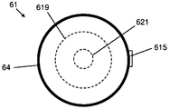
도 6a 및 도 6b는 각각 추가의 예시적인 용기(61)의 측면도 및 평면도이다. 용기(61)는, 용기(61)의 저장소(63) 내에서의 압력이 저장소(63)의 외측의 압력보다 충분히 낮아서, 저장소(63)가 이러한 차압의 결과로서 부분적으로 압괴되는 사용 시의 상태로 도시된다. 용기(61)는 상술된 용기(1)의 대응하는 구조체의 임의의 또는 모든 특징부를 가질 수도 있는 저장소(63), 보강 구조체(64), 출구 구조체(613) 및 입구 구조체(614)를 포함한다. 특정한 도시된 예시적인 용기(61)에 있어서, 보강 구조체(64)는 원통형 배럴(cylindrical barrel)을 포함한다. 이 배럴은 상대적으로 강성의 플라스틱 재료로 형성된다. 저장소(63)는 상대적으로 가요성이고 상대적으로 탄성 재료로 형성된 백(bag)을 포함한다. 이러한 백은 일단부에서 개방되고, 개방 단부의 에지는 배럴의 천장 단부에서, 배럴의 측벽에 기밀하게 부착된다. 이에 의해, 저장소(63)는 백에 의해, 그리고 배럴의 천장 단부/천장 벽에 의해 규정된다. 백 재료의 탄성은, 용기가 축조 재료로 충전될 때 백이 보강 구조체(64)의 형상에 일치하도록 한다. 백 재료는 용기가 축조 재료로 충전될 때 디폴트(default) 비신장 상태에 비해 신장될 수도 있다. 충전(그러므로 압괴되지 않은) 상태에서의 백의 형상은 파선(63b)에 의해 나타나고, 저장소가 부분적으로 압괴될 때 백의 형상은 실선(63a)에 의해 나타난다. 저장소(63)의 백 부분의 (저장소의 총 높이에 비해) 좁은 원주부는 (예를 들면, 글루에 의해) 보강 구조체(64)에 부착된다. 또한, 백의 하단부의 중앙부는 보강 구조체(64)의 베이스 벽에 부착된다.6A and 6B are side and plan views of a further
본 예시에서 배럴을 형성하는 재료는 기밀하다. 그러므로, 저장소(63)가 부분적으로 압괴된 형태를 채택하기 위해서 저장소의 부착되지 않은 부분이 배럴의 벽으로부터 멀리 이동하는 것을 허용하기 위해, 용기는 가스가 저장소와 외부 구조체 사이의 공간에 들어가게 하도록 추가의 가스 입구 구조체(615)를 포함한다. 추가의 가스 입구 구조체(615)는 선택적으로 가스가 저장소와 외부 구조체 사이의 공간에 들어가게 할 수도 있다. 추가의 가스 입구 구조체(615)는 용기의 천장 근처의 보강 구조체의 측벽에 제공된다. 저장소 백의 부착된 원주부는 배럴의 원주 주위로 연속되지 않고, 그에 따라 가스가 저장소와 보강 구조체 사이의 상부 공간(즉, 부착된 부분 위의 공간)과, 저장소와 보강 구조체 사이의 하부 공간(즉, 부착된 부분 아래의 공간) 사이를 통과할 수도 있다. 부착된 부분이 완전하고 연속적인 원주를 포함하는 다른 예시에 있어서, 추가적인 추가의 가스 입구 구조체는 가스가 하부 공간에 들어가게 하도록 제공될 수 있다.In this example, the material forming the barrel is airtight. Therefore, in order to allow the unattached portion of the reservoir to move away from the wall of the barrel in order to adopt the partially collapsed configuration of the
저장소(63)의 부분적으로 압괴된 상태에 있어서, 보강 구조체(64)에 부착되지 않은 저장소(63)의 부분[즉, 하부 부분(67)의 측벽(621) 및 상부 부분(65)의 측벽(619)]은 내측으로 이동/휘어지고, 그에 따라 저장소(63)의 이러한 부분과 보강 구조체(64) 사이에 갭이 생성된다는 것을 도 6a 및 도 6b로부터 알 수 있다. 게다가, 저장소 재료는 신장되고, 그에 따라 부착되지 않은 부분이 곡선 형상을 채택한다. 그러므로, 저장소는 부분적으로 압괴된 형태를 가질 때 디폴트 상태에 비해 변형된다. 저장소 재료의 탄성 및 보강부의 위치는 상부 부분 및 하부 부분을 포함하는 부분적으로 압괴된 형태를 생성하도록 협동되고, 이러한 상부 부분은 이 상부 부분의 높이에 걸쳐서 비-수렴하고, 이러한 하부 부분은 이 하부 부분의 높이에 걸쳐서 용기의 베이스를 향해 수렴한다.The portion of the
도 6a 및 도 6b의 용기(61)의 특정 예시는 본 명세서에서 설명된 용기의 다른 예시와 비교하여, 축조 재료의 상대적으로 높은 용적을 포함하기에 적합할 수도 있다. 게다가, 예시적인 용기(61)는 적층 가공 공정에서 사용하기 위한 3D 프린팅 시스템에 이미 제공되고 복귀된 사용된 축조 재료를 수용 및 저장하도록 사용하기에 적합할 수도 있다. 대안적으로 또는 추가적으로, 용기는 3D 프린팅 시스템에 버진 축조 재료를 제공하도록 사용하기에 적합할 수도 있다.Specific examples of
본 개시의 일부 예시적인 용기는 비충전된 상태에서 용기의 이송을 용이하게 할 수도 있다. 일부 이러한 예시적인 용기는, 예를 들면, 이러한 용기의 사용시 구성에 비해, 용기가 상대적으로 편평하고, 및/또는 상대적으로 작은 용적을 차지하는 구성으로 이송되도록 허용하는 특징부를 포함할 수도 있다. 이러한 예시적인 용기는 상대적으로 편평한 구성에서 사용시 구성으로의 용기의 재구성을 용이하게 하는 특징부를 포함할 수도 있다. 도 7a 내지 도 8b를 참조하여 이하에 설명되는 예시적인 용기는 비충전된 상태에서 용기의 이송을 용이하게 하는 하나 또는 여러 특징부를 포함한다.Some exemplary containers of the present disclosure may facilitate transport of the container in an unfilled state. Some such exemplary containers may include features that allow the container to be transported to a configuration that is relatively flat, and / or occupies a relatively small volume, as compared to, for example, the configuration at the time of use of such containers. Such an exemplary container may include features that facilitate the reconstitution of the container into a configuration in use in a relatively flat configuration. The exemplary container described below with reference to Figures 7A-8B includes one or more features that facilitate transport of the container in its unfilled state.
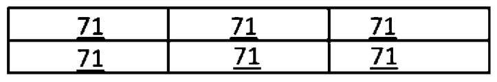
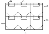
도 7a 및 도 7b는 6개의 용기(71)의 구성체의 측면도이다. 각 용기(71)는, 적층 가공 시스템이 용기(71)로부터 축조 재료를 수집할 수 있도록 적어도 부분적으로 충전된 조건에서 적층 가공 시스템에 연결되어야 하고, 축조 재료로 충전된 제 2 또는 추가의 유사한 용기로 교체가능하게 되기 위해 축조 재료의 고갈 후에 제거되어야 하는 교체가능한 소스 용기(71)일 수도 있다. 그러므로, 각 용기(71)는 3D 프린팅 축조 재료 용기이도록 고려될 수도 있다. 일례에 있어서, 축조 재료는 예를 들면, 상술된 바와 같은 유형 및/또는 입자 크기의 분말이다.Figs. 7A and 7B are side views of the constitution of six
각 용기(71)는 동일한 디자인을 가질 수도 있다. 대안적으로, 용기(71)는 다양한 디자인을 가질 수도 있다. 소정의 용기(71)는 축조 재료를 보유하도록 저장소를 포함한다. 용기(71)는 적어도 하나의 선택된 위치에서 저장소에 부착된 보강 구조체를 더 포함한다. 보강 구조체는 용기가 사용시 구성으로 있을 때 저장소의 적어도 하나의 부분의 절첩에 저항하도록 될 수도 있다. 저장소 및 보강 구조체는 상대적으로 편평한 구성에서 저장소가 축조 재료로 충전가능한 사용시 구성으로의 용기의 재구성을 허용한다. 도 7a에 있어서, 6개의 용기의 각각은 상대적으로 편평한 구성으로 구성되고, 도 7b에 있어서, 6개의 용기의 각각은 사용시 구성으로 구성된다. 상대적으로 편평한 구성을 갖는 용기의 스택(stack)의 높이가 사용시 구성을 갖는 용기의 스택의 높이보다 상당히 낮다는 것을 도 7a 및 도 7b로부터 알 수 있다. 저장소 및 보강 구조체는 상술된 저장소(3) 및 보강 구조체(4) 각각의 임의의 특징부를 포함할 수도 있다.Each
용기(71)는, 상술된 축조 재료 출구 구조체(13)의 임의의 특징부를 가질 수도 있고 축조 재료가 저장소를 빠져나가게 하는 축조 재료 출구 구조체를 더 포함할 수도 있다. 용기(71)는 가스가 저장소로 들어가게 하도록, 상술된 가스 입구 구조체(14)의 임의의 특징부를 가질 수도 있는 적어도 하나의 가스 입구 구조체를 더 포함할 수도 있다.The
사용시 구성의 용기에 의해 차지된 용적은 상대적으로 편평한 구성의 용기에 의해 차지된 용적보다 상당히 클 수도 있다. 사용시 구성의 용기에 의해 차지된 용적은 상대적으로 편평한 구성의 용기에 의해 차지된 용적보다 적어도 50% 클 수도 있다. 사용시 구성의 용기에 의해 차지된 용적은 상대적으로 편평한 구성의 용기에 의해 차지된 용적보다 적어도 80% 클 수도 있다. 상대적으로 편평한 구성에 있어서, 용기의 최소 외부 치수는 상대적으로 작은 값을 가질 수도 있고, 사용시 구성에 있어서, 용기의 최소 외부 치수는 상대적으로 큰 값을 가질 수도 있다.The volume occupied by the container in use during use may be significantly larger than the volume occupied by the container with a relatively flat configuration. The volume occupied by the container of the configuration in use may be at least 50% greater than the volume occupied by the container of relatively flat construction. In use, the volume occupied by the container in the configuration may be at least 80% greater than the volume occupied by the container in a relatively flat configuration. In a relatively flat configuration, the smallest outer dimension of the container may have a relatively small value, and in use, in use, the smallest outer dimension of the container may have a relatively large value.
저장소 및 보강 구조체 중 하나 또는 모두는 절첩가능할 수도 있다. 일부 예시에 있어서, 보강 구조체는 용기가 사용시 구성에 있을 때 입방형 구조체의 대향하는 측벽을 형성하는 한 쌍의 섹션을 포함하고, 한 쌍의 섹션의 각 섹션은 용기가 편평한 구성으로 있을 때 절첩된다. 일부 예시에 있어서, 보강 구조체는 단일 피스의 재료를 포함한다. 일부 예시에 있어서 보강 구조체는 판지로 형성된다.One or both of the reservoir and the reinforcing structure may be foldable. In some examples, the reinforcing structure includes a pair of sections that form opposite side walls of the cuboid structure when the container is in use in use, and each section of the pair of sections is folded when the container is in a flat configuration . In some examples, the reinforcing structure comprises a single piece of material. In some instances, the reinforcing structure is formed from a cardboard.
일부 예시에 있어서, 저장소는 상대적으로 가요성이고, 보강 구조체는 상대적으로 강성이다. 일부 예시에 있어서, 용기가 사용시 구성일 때, 저장소는 예를 들면, 실질적으로 수직의 측벽을 가질 수도 있는 비-수렴 상부 섹션과, 적어도 충전되고 압괴되지 않은 상태의 수렴 하부 섹션을 포함한다. 이러한 예시에 있어서, 적어도 하나의 선택된 위치는 상부 섹션 내에 포함될 수도 있다. 일부 예시에 있어서, 보강 구조체는 예를 들면, 실질적으로 수직의 측벽을 갖는 비-수렴 상부 섹션과 수렴 하부 섹션을 포함한다.In some examples, the reservoir is relatively flexible, and the reinforcing structure is relatively rigid. In some examples, when the container is in use in use, the reservoir includes, for example, a non-converging upper section, which may have a substantially vertical sidewall, and a converging lower section, which is at least fully filled and unbroken. In this example, at least one selected location may be included in the upper section. In some examples, the reinforcing structure includes, for example, a non-converging upper section and a converging lower section having substantially vertical sidewalls.
비충전된 상태의 용기의 이송을 용이하게 하기 위한 추가의 예시적인 용기(도시되지 않음)는, 상대적으로 가요성 재료로 형성되고 축조 재료를 수용 및 유지하기 위한 내부 부분과, 상대적으로 강성 재료로 형성되고 내부 부분 주위에 배치되며 1개 이상의 위치에서 내부 부분에 연결되는 외부 부분을 포함할 수도 있다. 추가의 예시적인 용기는, 용기의 최소 외부 치수가 상대적으로 작은 값을 갖는 제 1 구성과, 용기의 최소 외부 치수가 상대적으로 큰 값을 갖는 제 2 구성 사이에서 재구성가능하다.A further exemplary container (not shown) for facilitating the transfer of containers in the unfilled state includes an inner portion formed of a relatively flexible material and adapted to receive and hold the build material, And may comprise an outer portion disposed about the inner portion and connected to the inner portion at one or more locations. A further exemplary container is reconfigurable between a first configuration in which a minimum outer dimension of the container has a relatively small value and a second configuration in which a minimum outer dimension of the container has a relatively large value.
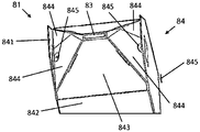
도 8a 및 도 8b는 추가의 예시적인 용기(81)를 도시한다. 용기(81)는 상술된 용기(81)의 대응하는 구조체의 임의의 특징부를 가질 수도 있는 저장소(83), 보강 구조체(84), 입구 구조체(814) 및 출구 구조체(813)를 포함한다. 도 8a는 상대적으로 편평한 구성의 용기(81)의 평면도이고, 도 8b는 사용시 구성의 용기(81)의 베이스 단부의 부분 사시도이다.8A and 8B show a further
저장소(83)의 형상 및 재료 특성은 상술된 용기(41)의 저장소(43)의 것과 동일할 수도 있다. 예를 들어, 저장소는 적은 탄성을 갖는 가요성 플라스틱 재료로 형성될 수도 있다. 저장소는 제 1 쌍의 대향하는 측벽이 절첩될 때까지 저장소의 제 1 쌍의 대향하는 측벽을 내측으로 압괴시키는 것에 의해 절첩가능하여, 제 2 쌍의 측벽이 서로를 향해 이동하게 하면서, 실질적으로 수직(예를 들면, 비절첩)인 채로 남아있게 한다. 각각의 압괴가능한 대향하는 측벽의 각 에지에 실질적으로 평행하고 각 에지로부터 등거리에 있는 절첩 선 또는 크리즈(crease)가 제공되어 측벽이 어떻게 압괴되는지를 제어하는데 도움이 될 수도 있다. 사실상, 압괴는 그래서, 구조체가 압괴될 때 절첩 선을 따라 내측으로 절첩하는 압괴가능한 대향하는 측벽에 의해 발생한다. 대안적으로, 이러한 접근에 의해 편평화된 저장소가 보다 큰 풋프린트에 존재하더라도, 구조체가 압괴될 때, 압괴는 절첩 선을 따라 외측으로 절첩하는 압괴가능한 대향하는 측벽에 의해 발생할 수도 있다. 다른 이러한 절첩 선 또는 크리즈는 유사한 방식으로 압괴를 돕도록 전개(deploy)될 수도 있다. 제 2 쌍의 측벽 사이의 거리는 저장소(83)가 비절첩될 때보다 저장소(83)가 절첩될 때가 상당히 좁다. 저장소(83)의 형상은, 절첩될 때 입구 구조체(814) 및 출구 구조체(813)가 제공되는 저장소의 부분이 실질적으로 수직인 채로 남아있도록 한다.The shape and material properties of the
사용시 구성의 보강 구조체(84)의 형상은 상술된 용기(51)의 보강 구조체(54)의 형상과 유사하고, 그에 따라 보강 구조체(84)는 제 1 상부 쌍의 비-수렴 대향하는 측벽과, 제 2 상부 쌍의 비-수렴 대향하는 측벽과, 4개의 수렴 하부 측벽을 포함한다. 그러나, 상부 쌍의 대향하는 측벽 중 하나는 보강 구조체(84)의 전체 높이(즉, 상부 및 하부 섹션의 결합 높이) 정도 연장된다. 이에 의해, 이러한 연장된 측벽의 하단부는 수직의 사용시 배향으로 용기를 지지 및 보유하도록 수렴 하부 섹션의 베이스와 협동할 수 있다.The configuration of the reinforcing
보강 구조체(84)는, 한 쌍의 연장된 측면 패널(841), 한 쌍의 비-연장된 측면 패널(842)(이들 중 오직 하나만이 도 8a 및 도 8b에서 볼 수 있음), 비-연장된 측면 패널(842)의 하부 에지에 각각 결합되는 한 쌍의 하부 섹션 측면 패널(843), 2개의 쌍의 하부 섹션 플랩(flap)(844)(이들 중 오직 하나만이 도 8a에서 볼 수 있음)을 포함하는 단일 피스의 판지로 형성될 수도 있다. 연장된 측면 패널(841)은 이들이 비-연장된 측면 패널(842)보다 (사용시 배향에 비해) 더 높은 높이를 갖는다는 의미로 연장된다. 소정 쌍의 하부 섹션 플랩(844)의 각 하부 섹션 플랩은 소정의 하부 섹션 측면 패널(843)의 상이한 에지에 결합된다. 다양한 구멍(845)이 보강 구조체(84) 내에 제공된다. 이 구멍(845)은 예를 들면, 보강 구조체의 제 1 부분을 사용시 배향의 제 2 부분에 부착시키기 위해 및/또는 저장소를 보강 구조체에 부착시키기 위해, 파스너를 수용하도록 될 수도 있다. 하부 섹션 측면 패널 및 하부 섹션 플랩은, 용기(81)가 (도 8b에 도시된 바와 같은) 사용시 배향으로 있을 때 하부 섹션 측면 패널 및 하부 섹션 플랩이 피라미드형 구조체를 형성하기 위해 협동하도록 형상설정된다. 다양한 패널 및 플랩 사이의 결합은 결합의 축을 중심으로 결합된 부분들 사이의 각운동을 허용한다.The reinforcing
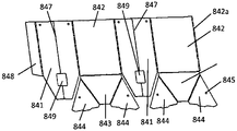
도 8c는 보강 구조체를 형성할 수도 있는 비절첩 및 비조립된 상태의 단일 피스의 재료를 도시한다. 각각의 연장된 측면 패널(841)이 윈도우(849)를 포함한다는 것을 도 8c로부터 알 수 있다. 저장소(83)가 투명 재료로 형성되는 예시에 있어서, 이러한 윈도우는 저장소(83) 내에 포함된 축조 재료의 레벨을 보는데 사용될 수 있다. 각 연장된 측면 패널(841)은 중앙 절첩-선, 크리즈 또는 힌지(847)를 포함한다는 것을 또한 알 수 있다. 이러한 크리즈는 연장된 측면 패널이 용기(81)의 상대적으로 편평한 구성과 사용시 구성 사이에서의 전환 동안에, 절첩 및 비절첩하게 한다. 연장된 측면 패널(841) 중 하나는 다른 하나의 측면 패널에 결합되지 않은 긴 에지로부터 돌출하는 탭(tab)(848)을 구비한다. 보강 구조체를 조립하기 위해, 탭(848)은 비-연장된 측면 패널(842)의 자유 긴 에지(842a)에 접착 또는 그렇지 않으면 부착 또는 고정된다. 이에 의해, 재료 피스는 연속적인 루프(loop)를 형성한다. 용기의 조립 동안에, 저장소(83)는 재료 피스가 루프를 형성되기 전 또는 후에, 적어도 하나의 선택된 위치에서 보강 구조체(84)의 재료 피스에 부착될 수도 있다.FIG. 8C shows a single piece material in the non-assembled state and the unassembled state, which may form a reinforced structure. It can be seen from Fig. 8C that each
도 8a에 도시된 상대적으로 편평한 구성에서 도 8b에 도시된 사용시 구성으로 용기(81)를 재구성하기 위해, 연장된 측면 패널(841)은 절첩되고, 이는 보강 구조체(84)가 실질적으로 입방 형상을 채택하게 한다. 저장소(83)는, 이 저장소(83)와 보강 구조체(84) 사이의 부착에 의해, 동시에 비절첩 및/또는 확장되어질 수도 있다. 보강 구조체의 수렴 하부 섹션의 피라미드 형상을 생성하기 위해, 제 1 하부 섹션 측면 패널(843)에 연결된 플랩(844)은 도 8b에 도시된 바와 같이, 제 2 하부 섹션 측면 패널(843)의 대응하는 플랩(844)과 중첩되고 플랩(844)에 부착된다. 플랩(844)의 부착은 예를 들면, 파스너를 접착하는 것에 의해, 및/또는 파스너를 플랩(845) 내의 구멍(845)을 통해 삽입하는 것에 의해 이루어질 수도 있다. 이러한 파스너는 추가적으로, 플랩(844)을 저장소(83)에 부착할 수도 있다. 용기(84)는 상술된 공정을 역전하는 것에 의해 상대적으로 편평한 구성으로 다시 재구성될 수도 있다.8A, the
일부 예시에 있어서, 용기는 보강 구조체를 사용시 구성으로 유지하도록 지지 구조체를 더 포함할 수도 있다. 지지 구조체는 용기가 편평한 구성으로 있을 때에는 보강 구조체 및 저장소로부터 분리가능하고, 용기가 사용시 구성으로 있을 때에는 보강 구조체에 연결될 수도 있다. 지지 구조체는 절첩가능할 수도 있다. 지지 구조체는 상대적으로 편평한 구성과 사용시 구성 사이에서 재구성가능할 수도 있다. 지지 구조체의 형상은 보강 구조체의 형상에 대응할 수도 있다. 지지 구조체는 보강 구조체의 일부 또는 전부를 둘러싸도록 형상설정된 슬리브 또는 박스를 포함할 수도 있다.In some examples, the container may further comprise a support structure to maintain the reinforcing structure in use. The support structure may be detachable from the reinforcement structure and reservoir when the container is in a flat configuration and may be connected to the reinforcement structure when the container is in use in use. The support structure may be foldable. The support structure may be reconfigurable between the relatively flat configuration and the configuration in use. The shape of the support structure may correspond to the shape of the reinforcing structure. The support structure may include a sleeve or box configured to surround some or all of the stiffening structure.
용기(81)의 특정한 예시적인 지지 구조체(도시되지 않음)는 사용시 구성의 보강 구조체에 걸쳐서 안락하게 끼워맞춤되도록 형상설정된 단부-개방형(open-ended) 판지 슬리브를 포함한다. 지지 구조체는 사용시 구성에서 입방형이고, 4개의 측면 패널을 구비하며, 각각의 측면 패널은 보강 구조체(84)의 측면 패널에 대응한다. 지지 구조체는 측면 패널들 사이의 결합 부분에서 절첩되지만, 측면 패널 중 어느 것도 자체적으로 절첩가능하지 않다. 상대적으로 편평한 구성에 있어서, 지지 구조체는 (의도된 사용시 배향에 대해서) 자유 수직 에지를 각각 구비하는 2개의 측면 패널을 구비한다. 자유 수직 에지는 상대적으로 편평한 구성에서 지지 구조체의 대향 단부에 위치된다. 지지 구조체를 재구성하는 것은 2개의 자유 수직 에지를 함께 부착하는 것을 포함한다. 자유 수직 에지가 함께 부착되기 전 또는 후에, 지지 구조체는 보강 구조체(84)의 주위에 배치된다. 지지 구조체는 예를 들면, 글루 또는 파스너를 사용하여 보강 구조체(84)에 부착될 수도 있고, 또는 대안적으로, 보강 구조체(84)의 측면 패널과 지지 구조체의 측면 패널 사이의 마찰 접촉에 의해 보강 구조체의 주위에 배치된 채로 남아있을 수도 있다. 지지 구조체의 측면 패널은 상대적으로 단단하고, 보강 구조체(84)의 연장된 측면 패널(841)에 비해 절첩이 불가능하다. 그러므로, 지지 구조체는 연장된 측면 패널(841)의 절첩에 저항하고, 이에 의해 사용시 구성의 보강 구조체(84)를 유지하는데 도움을 줄 수도 있다.A particular exemplary support structure (not shown) of the
본 개시의 일부 예시적인 용기는 충전된 상태에서 용기의 취급을 용이하게 할 수도 있다. 일부 이러한 예시적인 용기는 예를 들면, 용기가 사람에 의해 편안하게 들어올려지고 이동되는 것을 허용하는 특징부를 포함할 수도 있다. 일부 이러한 예시적인 용기는 예를 들면, 이 용기로부터 수동으로 축조 재료를 비우기 위해, 예를 들면, 사람에 의해 용기를 기울이거나, 뒤집거나, 또는 그렇지 않으면 다루는 것을 용이하게 하는 특징부를 포함할 수도 있다. 도 9 내지 도 11을 참조하여 이하에 설명되는 예시적인 용기는 충전된 상태의 용기의 취급을 용이하게 하는 하나 또는 여러 특징부를 포함한다.Some exemplary containers of the present disclosure may facilitate handling of the container in a charged state. Some of these exemplary containers may, for example, include features that allow the container to be comfortably lifted and moved by a person. Some such exemplary containers may include features that facilitate, for example, emptying the build material from the container manually, for example, by tilting, inverting, or otherwise handling the container by a person . The exemplary container described below with reference to Figures 9-11 includes one or more features that facilitate handling of the container in its fully filled state.
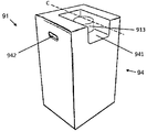
도 9는 사용시 배향의 예시적인 용기(91)의 사시도이다. 용기(91)는, 적청 가공 시스템이 용기(91)로부터 축조 재료를 수집할 수 있도록 적어도 부분적으로 충전된 조건에서 적층 가공 시스템에 연결되고, 축조 재료로 충전된 제 2 또는 추가의 유사한 용기로 교체가능하게 되기 위해 고갈 후에 제거되는 교체가능한 소스 용기(91)일 수도 있다. 그러므로, 용기(91)는 3D 프린팅 축조 재료 용기인 것으로 고려될 수도 있다. 일례에 있어서, 축조 재료는 예를 들면, 상술된 바와 같은 유형 및/또는 입자 크기의 분말이다.9 is a perspective view of an
용기(91)는 축조 재료를 보유하기 위한 것이고, 축조 재료가 용기(91)의 내부 공간을 빠져나가게 하도록 축조 재료 출구 구조체(913)를 포함한다. 용기의 외부 공간은 리세스된 부분(941)을 포함한다. 리세스된 부분(941)은 축조 재료 출구 구조체(913)를 지지한다. 축조 재료 출구 구조체는 상술된 용기(1, 41, 51, 61 또는 71)의 축조 재료 출구 구조체의 임의의 특징부를 가질 수도 있다.The
일부 예시에 있어서, 용기(91)는 축조 재료를 보유하는 저장소(볼 수 없음)와, 이 저장소 주위에 배치된 외부 구조체(94)를 추가로 포함한다. 이러한 예시에 있어서, 축조 재료 출구 구조체(913)는 축조 재료가 저장소를 빠져나가게 하는 것이다. 저장소는 상술된 용기(1, 41, 51, 61 또는 71)의 대응하는 구조체의 임의의 특징부를 가질 수도 있다. 외부 구조체는 용기의 외부면을 형성하고, 이 외부면 내의 리세스된 부분(941)을 포함한다. 도시된 예시에 있어서, 리세스된 부분은 용기(91)의 상부 부분 내에 있다. 용기(91)는 상술된 가스 입구 구조체(14)의 임의의 특징부를 가질 수도 있고 가스가 저장소로 들어가게 하는 가스 입구 구조체(도시되지 않음)를 더 포함할 수도 있다. 이러한 가스 입구 구조체는 예를 들면, 축조 재료 출구 구조체(913)와 유사한 방식으로, 리세스된 부분(941)에 의해 지지될 수도 있다.In some examples, the
리세스된 부분(941)은 출구 구조체(913)를 지지한다. 외부 구조체는 상술된 보강 구조체의 임의의 특징부를 갖는 보강 구조체를 포함할 수도 있다. 외부 구조체는 상술된 지지 구조체의 임의의 특징부를 갖는 지지 구조체를 포함할 수도 있다. 리세스된 부분(941)은 용기(91)의 (사용시 배향에 대해서) 천장면의 일부가 리세스되고, 용기의 측면의 일부가 리세스되도록 된다. 천장면에 대해서, 리세스된 부분(941)은 리세스된 부분의 가상의 중앙-선(C)은 천장면의 2개의 평행한 대향하는 에지로부터 등거리로 이격되도록, 중앙에 위치될 수도 있다. 그래서, 리세스된 부분(941)은 용기의 천장면과 일치하는 상부면을 갖는 직립(upstanding) 숄더부에 의해 적어도 2개의 측부 상에서 경계지어질 수도 있다. 도시된 예시에 있어서, 리세스된 부분은 직립 숄더부에 의해 3개의 측부 상에서 경계지어진다. 임의의 경우에서, 2개 또는 3개의 직립 숄더부는 리세스된 부분 내에 위치되는 임의의 구조적인 요소를 보호하고, 리세스된 부분 주위의 용기(91)를 보강하는 역할을 한다. 이에 의해, 용기의 천장 에지는 리세스된 부분(941)에 의해 중단된다. 다른 예시에 있어서, 리세스된 부분은, 용기의 천장면의 일부가 리세스되고 측면이 리세스되지 않아서 리세스된 부분을 둘러싸는 효과적으로 4개의 숄더부가 존재하거나, 용기의 측면의 일부가 리세스되고 천장면이 리세스되지 않도록 될 수도 있다. 리세스된 부분은 다른 형태가 가능하더라도, 대체로 정사각형 또는 직사각형 입방 형태를 가질 수도 있다.The recessed
출구 구조체(913)의 외부 부분은 이 출구 구조체가 외부면으로부터 돌출하지 않도록, 리세스된 부분(941) 내에 포함될 수도 있다(예를 들면, 출구 구조체의 외부 부분이 리세스된 부분의 각각의 가상의 정사각형 또는 직사각형 입방 형태의 외부 경계 내에 남아있음). 일부 예시에 있어서, 출구 구조체(913)의 외부 부분[및 가스 입구 구조체와 같이, 리세스된 부분(941)에 의해 지지된 임의의 다른 구조체]은 리세스된 부분(941) 내에 완전히 포함될 수도 있다. 이러한 특징부는 용기(91)의 저장, 이송 또는 다른 취급 동안에, 출구 구조체[및 리세스된 부분(941)에 의해 지지된 임의의 다른 구조체]가 손상되는 것으로부터 보호할 수도 있고, 및/또는 용기(91)의 스태킹(stacking)을 용이하게 할 수도 있다. 숄더부는 리세스된 부분 주위의 용기를 보강하는 역할을 한다. 리세스된 부분의 양측 상에 동일하게 넓은 대향하는 숄더부를 구비하는 것은 용기의 천장면을 가로질러서, 동일하고 일정한(even) 지지력을 제공하는 역할을 하고, 이러한 힘은 용기(들)의 스태킹을 도울 수도 있다. 출구 구조체(913)의 천장면은 외부 구조체(94)의 천장면보다 낮을 수도 있고, 이에 의해 용기(91)의 천장면보다 낮을 수도 있다. 출구 구조체(913)의 천장면은 외부 구조체(94)의 천장면과 동일한 평면 내에, 및/또는 용기(91)의 천장면과 동일한 평면 내에 있을 수도 있다. 출구 구조체는 용기의 천장면의 적어도 2개의 대향하는 에지에 대해 대체로 중앙 위치에 위치될 수도 있다. 출구 구조체는 용기의 천장면 전체에 대해 대체로 중앙 위치에 위치될 수도 있다. 이는 용기로부터의 축조 재료의 효율적인 추출을 용이하게 할 수도 있고, 예를 들면, 스태킹 목적을 위해, 용기의 천장면을 가로질러서 일정한 지지력을 제공하기 위해서, 용기의 적어도 양측 상에의 동일하게 넓은 숄더부의 제공을 또한 용이하게 할 수도 있다.The outer portion of the
도시된 예시에 있어서, 용기(91)는 외부 구조체(94)의 대향 측부 상에 제공된 한 쌍의 핸들(이들 중 오직 하나만이 볼 수 있음)을 더 포함한다. 핸들(942)은 컷아웃부[즉, 외부 구조체(94)의 벽의 개구부]를 포함한다. 다른 예시에 있어서, 핸들은 외부 구조체의 외부면에 부착된 리세스 또는 구조체를 포함할 수도 있다. 핸들(942)은 외부 구조체와 일체형으로 형성될 수도 있다. 핸들은 용기가 사용시 배향으로 있을 때, 용기의 전체 높이의 3등분 중 상부에 포함될 수도 있다.In the illustrated example, the
외부 구조체의 치수는 사람에 의한 용기의 들어올림 및/또는 이동을 용이하게 하도록 선택될 수도 있다. 예를 들어, 한 쌍의 핸들(942) 사이의 외부 구조체(94)의 폭은 외부 구조체의 깊이보다 넓을 수도 있고, 폭 및 깊이는 외부 구조체의 높이보다 작을 수도 있다. 저장소의 용적은 20L 내지 70L의 범위에 있을 수도 있다. 저장소의 용적은 20L 내지 100L의 범위에 있을 수도 있다. 일부 예시에 있어서, 저장소의 용적은 20L보다 작을 수도 있다. 일부 예시에 있어서, 저장소의 용적은 100L보다 클 수도 있다. 외부 구조체의 높이는 0.3m 내지 1m의 범위에 있을 수도 있다. 일부 예시에 있어서, 외부 구조체의 높이는 0.3m보다 낮을 수도 있다. 일부 예시에 있어서, 외부 구조체의 높이는 1m보다 높을 수도 있다. 외부 구조체의 높이는 0.5m 내지 0.75m의 범위에 있을 수도 있다. 외부 구조체의 높이는 대략 0.55m일 수도 있다. 핸들 사이의 외부 구조체의 폭은 0.25m 내지 0.5m의 범위에 있을 수도 있다. 핸들 사이의 외부 구조체의 폭은 0.1m 내지 0.75m의 범위에 있을 수도 있다. 일부 예시에 있어서, 핸들 사이의 외부 구조체의 폭은 0.25m보다 작을 수도 있다. 일부 예시에 있어서, 핸들 사이의 외부 구조체의 폭은 0.75m보다 클 수도 있다. 핸들 사이의 외부 구조체의 폭은 대략 0.3m일 수도 있다. 외부 구조체의 깊이는 0.1m 내지 0.75m의 범위에 있을 수도 있다. 일부 예시에 있어서, 외부 구조체의 깊이는 0.1m보다 작을 수도 있다. 일부 예시에 있어서, 외부 구조체의 깊이는 0.75m보다 클 수도 있다. 외부 구조체의 깊이는 0.2m 내지 0.5m의 범위에 있을 수도 있다. 외부 구조체의 깊이는 대략 0.2m일 수도 있다.The dimensions of the outer structure may be selected to facilitate lifting and / or movement of the container by the person. For example, the width of the
외부 구조체(94)는 단일 피스의 재료로 형성될 수도 있다. 외부 구조체(94)는 판지로 형성될 수도 있다. 저장소 및 외부 구조체(94) 중 하나 또는 전부는 절첩가능할 수도 있다. 일부 예시에 있어서, 저장소는 압괴가능하고, 외부 구조체(94)는 저장소의 적어도 하나의 보강부의 압괴에 저항하도록 상대적으로 강성의 보강 구조체를 포함한다. 다른 예시에 있어서, 저장소는 압괴가능하고, 용기(91)는 저장소의 적어도 하나의 보강부의 압괴에 저항하도록 상대적으로 강성의 보강 구조체를 더 포함한다. 이러한 예시에 있어서, 보강 구조체는 저장소와 외부 구조체(94) 사이에 배치될 수도 있다. 외부 구조체(94)는 가스가 외부 구조체(94)와 저장소 사이의 공간으로 들어가게 하도록 할 수도 있다.The
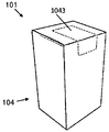
도 10a 및 도 10b는 사용시 배향으로 도시된 추가의 예시적인 용기(101)의 사시도이다. 용기(101)는 상술된 용기(91)의 대응하는 구조체의 임의의 특징부를 가질 수도 있는 저장소(볼 수 없음)와, 축조 재료 출구 구조체(1013)와, 외부 구조체(104)와, 리세스된 부분(1041)을 포함한다. 용기(101)는 리세스된 부분(1041)에 걸쳐서 배치된 재료의 제거가능한 부분(1043)을 더 포함하고, 그에 따라 출구 구조체의 외부 부분이 외부 구조체(104)의 리세스된 부분 및 재료의 제거가능한 부분(1043)에 의해 경계지어진 공간 내에 밀폐된다. 도 10a에서, 제거가능한 부분(1043)은 용기(101) 상에 배치되고, 도 10b에서, 제거가능한 부분(1043)은 용기(101)로부터 제거되었다. 재료의 제거가능한 부분(1043)은 적어도 용기(101)로부터의 제거 이전에, 외부 구조체와 일체로 되어 있을 수도 있다. 외부 구조체(104)는 판지를 포함할 수도 있고, 재료의 제거가능한 부분(1043)은 이 제거가능한 부분(1043)의 에지에서의 합지의 파괴를 용이하게 하도록, 천공된 또는 그렇지 않으면 취약선(weakended line)에 의해 규정될 수도 있다. 제거가능한 부분(1043)은 외부 구조체(104)의 천장면의 일부를 형성할 수도 있다. 제거가능한 부분(1043)은 외부 구조체(104)의 측면의 일부를 형성할 수도 있다. 제거가능한 부분(1043)은 용기(101)로부터의 제거가능한 부분(1043)의 제거를 용이하게 하도록 하나 또는 여러 특징부(예를 들면, 컷-아웃부, 돌출부, 탭, 핸들 등)를 포함할 수도 있다. 임의의 이벤트에 있어서, 제거가능한 부분(1043)(제거되기 전)은 리세스된 부분 내에 있는 출구 구조체(1013)와 같은 임의의 요소를 위한 추가의 보호를 제공한다.10A and 10B are perspective views of a further
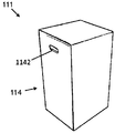
도 11은 추가의 예시적인 용기(111)의 사시도이다. 용기(111)는 축조 재료를 보유하기 위한 것이고, 용기의 대향 측부 상의 한 쌍의 핸들(1142)(이들 중 오직 하나만이 볼 수 있음)을 포함한다. 핸들(1142) 사이의 용기의 폭은 용기의 깊이보다 크고, 용기의 높이보다 작다.11 is a perspective view of a further
일부 예시에 있어서, 용기(111)는 상술된 용기(91) 또는 용기(101)의 대응하는 구조체의 임의의 특징부를 가질 수도 있는 저장소(볼 수 없음)와, 축조 재료 출구 구조체(볼 수 없음)와, 외부 구조체(114)를 포함한다. 이러한 예시에 있어서, 한 쌍의 핸들(1142)은 외부 구조체의 대향 측부 상에 제공될 수도 있고, 핸들(1142) 사이의 외부 구조체의 폭은 외부 구조체의 깊이보다 크고, 외부 구조체의 높이보다 작을 수도 있다.In some examples, the
도 12는 축조 재료 제거 구성체(1259)를 거쳐서, 3D 프린팅 시스템(1291)에 축조 재료를 제공하는데 사용되는 예시적인 용기(121)를 도시한다. 축조 재료 제거 구성체(1259)는 임의의 적합한 연결 기술을 사용하여[예를 들면, 출구 구조체(1273) 상에, 그리고 축조 재료 제거 시스템(1259)의 연결 부재 상에 제공된 대응하는 자성 커넥터를 거쳐서], 용기(121)의 축조 재료 출구 구조체(1273)에 연결된다. 용기(121) 및 그 내부에 포함된 구조체는 용기(1, 41, 51, 61, 71, 81, 91, 101 또는 111)에 관련하여 상술된 임의의 특징부를 가질 수도 있다. 3D 프린팅 시스템은 축조 재료를 사용하여 3D 물체를 생성하기 위한 적층 가공 시스템일 수도 있다. 3D 프린팅 시스템은 3D 프린팅부 및 개별의 축조 재료 관리부를 포함할 수도 있다. 대안적으로, 3D 프린팅 시스템은 단일 장치 내에 통합된 3D 프린팅 기능 및 축조 재료 관리 기능을 포함할 수도 있다. 축조 재료 제거 시스템은 흡입을 통해 용기로부터 축조 재료를 추출하는 흡인 시스템을 포함할 수도 있다.12 shows an
도 13 및 도 14는 예시적인 용기(121)로부터 3D 프린팅 시스템(1291)으로 축조 재료를 제공하기 위한 방법의 예시를 실행하는 흐름도이다. 맥락상의 예시를 제공하기 위해 도 1 내지 도 12의 도면이 참조된다. 그러나, 실행은 이러한 예시에 한정되지 않는다.Figures 13 and 14 are flow charts illustrating an example of a method for providing a build material from an
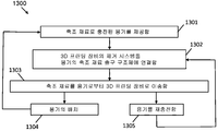
도 13은 예를 들면, 용기로부터 3D 프린팅 시스템에 축조 재료를 제공하는 예시적인 방법(1300)을 도시한다. 블럭(1301)에서, 축조 재료로 충전된 용기[예를 들면, 용기(131)]가 제공된다. 축조 재료는 버진 축조 재료일 수도 있다. 축조 재료는 사용된 축조 재료일 수도 있다. 용기를 제공하는 것은 용기를 제조, 이송, 저장, 조립 및/또는 충전하는 것 중 임의의 하나 또는 전부를 포함할 수도 있다. 일부 예시에 있어서, 용기를 제공하는 것은 실질적으로 편평한 구성에서 사용시 구성으로 용기를 재구성하는 것과, 그 다음에, 용기를 버진 축조 재료로 충전하는 것을 포함한다. 용기를 제공하는 것은 도 12에 도시된 바와 같이, 3D 프린팅 장비 근처에 또는 3D 프린팅 장비에 인접하여 용기를 배치하는 것을 포함할 수도 있다. 용기를 제공하는 것은 축조 재료 제거 시스템의 연결 부재에 의해 도달가능한 위치에 용기를 배치하는 것을 포함할 수도 있다.13 illustrates an
블럭(1302)에서, 3D 프린팅 장비[예를 들면, 3D 프린팅 시스템(1291)]의 축조 재료 제거 시스템은 용기의 축조 재료 출구 구조체에 연결된다. 제거 시스템을 출구 구조체에 연결하는 것은 제거 시스템의 커넥터를 출구 구조체의 대응하는 커넥터에 정합시키는 것을 포함할 수도 있다. 제거 시스템의 커넥터는 예를 들면, 연결 부재의 원위 단부에 제공될 수도 있다. 제거 시스템이 흡인 시스템을 포함하는 예시에 있어서, 이러한 연결 부재는 진공 호스를 포함할 수도 있다. 제거 시스템을 출구 구조체에 연결하는 것은 제거 시스템과 출구 구조체 사이에 기밀 시일을 생성하는 것을 포함할 수도 있다. 일부 예시, 예를 들면, 3D 프린팅 장비가 축조 재료 제거 시스템을 포함하지 않는 예시에 있어서, 이러한 블럭은 생략될 수도 있다.At
블럭(1303)에 있어서, 축조 재료는 용기로부터 3D 프린팅 장비로 이송된다. 축조 재료를 이송하는 것은 예를 들면, 3D 프린팅 장비의 축조 재료 제거 시스템을 활성화시키는 것을 포함할 수도 있다. 축조 재료를 이송하는 것은 (도 12의 블럭 화살표에 의해 나타낸 바와 같이) 흡입력을 용기의 저장소의 내부 공간에 인가하는 것을 포함할 수도 있다. 축조 재료를 이송하는 것은 용기의 저장소를 흡인하는 것을 포함할 수도 있다. 출구 구조체가 3D 프린팅 장비의 제거 시스템에 연결되지 않은 예시에 있어서, 축조 재료를 이송하는 것은 용기를 수동으로 기울이는 것을 포함할 수도 있고, 그에 따라 축조 재료는 3D 프린팅 장비의 출구 구조체의 외부로, 그리고 입구 구조체 내로 흐른다. 재료는 용기가 비워질 때까지 용기로부터 3D 프린팅 장비로 연속적으로 이송될 수도 있다. 재료는 예를 들어, 소정의 3D 프린팅 작업이 용기 내에 포함된 것보다 축조 재료를 덜 사용하는 경우에 불연속적으로 이송될 수도 있다.At
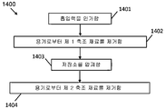
도 14는 예를 들면, 용기[예를 들면, 용기(121)]로부터 3D 프린팅 시스템[예를 들면, 3D 프린팅 시스템(1291)]로 축조 재료를 이송하는 예시적인 방법(1400)을 도시한다. 예시적인 방법(1400)은 예시적인 방법(1300)의 블럭(1303)의 일부로서 수행될 수도 있다. 예시적인 방법(1400)은 축조 재료를 보유하는 압괴가능 저장소와, 저장소의 적어도 하나의 보강부의 압괴에 저항하는 상대적으로 강성의 보강 구조체를 포함하는 용기[예를 들면, 용기(1, 41 또는 51)의 임의의 특징부를 갖는 용기]에 의해 수행될 수도 있다. 예시적인 방법(1400)은 흡인 시스템의 형태의 축조 재료 제거 시스템을 구비하는 3D 프린팅 시스템에 의해 수행될 수도 있다.Figure 14 illustrates an
블럭(1401)에서, 흡입력은 예를 들면, 용기의 저장소의 내부 공간에 인가된다. 흡입력은 저장소의 내부 공간 내로 연장되는 흡인 튜브를 거쳐서 인가될 수도 있다. 이에 의해 흡입력은 저장소의 하단부, 또는 하단부 근처의 위치에 인가될 수도 있다. 흡입력은 사전결정된 규모를 가질 수도 있다. 사전결정된 규모는 축조 재료의 재료 특성, 저장소의 재료 특성, 저장소의 크기, 저장소의 형상, 저장소 내에 포함된 축조 재료의 양 등과 같은 요인에 기반하여 결정될 수도 있다. 흡입력은 임의의 적합한 기술을 사용하여 흡인 시스템에 의해 발생될 수도 있다.At
블럭(1402)에 있어서, 제 1 축조 재료는 용기로부터 제거된다. 제 1 축조 재료를 용기로부터 제거하는 것은 제 1 축조 재료를 저장소로부터 제거하는 것을 포함할 수도 있다. 제 1 축조 재료를 용기로부터 제거하는 것은 예를 들면, 흡입력의 영향 하에서, 흡인 튜브를 통해 제 1 축조 재료를 이송시키는 것을 포함할 수도 있다. 제 1 축조 재료를 용기로부터 제거하는 것은 저장소를 통해 (예를 들면, 가스가 용기의 가스 입구 구조체를 통해 들어가는 것을 허용하는 것에 의해) 가스의 유동을 생성하는 것과, 축조 재료를 기류 내로 유입(entrain)시키는 것을 포함할 수도 있다. 가스는 공기일 수도 있다. 일부 예시에 있어서, 가스는 공기 외에 질소와 같은 가스일 수도 있다. 가스는 비활성 기체일 수도 있다. 일부 예시에 있어서, 가스는 산소를 포함하지 않는다. 제 1 축조 재료를 용기로부터 제거하는 것은 제 1 축조 재료를 흡인하는 것을 포함할 수도 있다. 제 1 축조 재료는 저장소 내에 포함된 축조 재료의 총량의 일부를 포함할 수도 있다. 제 1 축조 재료는 저장소 내에 포함된 축조 재료의 총량의 50% 이하를 포함할 수도 있다. 제 1 축조 재료는 저장소의 벽에 부착된 축조 재료를 포함하지 않을 수도 있다. 제 1 축조 재료는 축조 재료의 구조체 내에 포함된 축조 재료를 포함하지 않을 수도 있다.In
블럭(1403)에서, 저장소는 압괴된다. 저장소를 압괴하는 것은 저장소의 하나 또는 여러 비-보강부를 압괴하는 것을 포함할 수도 있다. 저장소를 압괴하는 것은 부분적으로 압괴된 형태를 채택하는 저장소를 포함할 수도 있다. 부분적으로 압괴된 형태는 용기(1, 41, 51 및 61)에 관련하여 상술된 임의의 특징부를 가질 수도 있다. 일부 예시에 있어서, 저장소를 압괴하는 것은 예를 들면, 저장소 내의 압력이 저장소 외측의 압력보다 낮도록, 저장소의 내측과 저장소의 외측 사이에 차압을 생성하는 것을 포함한다. 저장소를 압괴하는 것은 저장소의 내측과 저장소의 외측 사이의 차압에 응답하여 임계값에 도달하는 것을 발생시킬 수도 있다. 저장소를 압괴하는 것에 의해 저장소의 벽에 부착된 축조 재료를 축출(dislodging)하는 것으로 이어질 수도 있다.At
블럭(1404)에서, 제 2 축조 재료는 용기로부터 제거된다. 제 2 축조 재료를 용기로부터 제거하는 것은 제 1 축조 재료를 용기로부터 제거하는 것과 동일한 방식으로 수행될 수도 있다. 제 2 축조 재료는 용기 내에 포함된 축조 재료의 총량의 일부를 포함할 수도 있다. 제 2 축조 재료는 제 1 축조 재료의 제거에 이어서, 저장소 내에 남아있는 모든 또는 실질적으로 모든 축조 재료를 포함할 수도 있다. 제 2 축조 재료는 제 1 축조 재료의 제거에 이어서, 저장소 내에 남아있는 축조 재료의 일부를 포함할 수도 있다. 제 2 축조 재료는 저장소의 벽으로부터 축출된 축조 재료를 포함할 수도 있다. 제 2 축조 재료는 축조 재료의 구조체 내에 이전에(즉, 저장소의 압괴 전에) 포함된 축조 재료를 포함할 수도 있다.At
일부 예시에 있어서, 블럭(1203)의 수행에 이어서, 용기는 블럭(1204)에서 배치될 수도 있다. 용기의 배치는 (예를 들면, 인간 오퍼레이터에 의해, 또는 3D 프린팅 장비의 자동화 시스템 및/또는 용기에 의해) 용기가 비어있거나, 실질적으로 비어있고, 및/또는 용기가 임계량 미만의 축조 재료를 포함하는 검출에 응답하여 수행될 수도 있다. 용기의 배치는 (예를 들어, 인간 오퍼레이터 및/또는 3D 프린팅 장비의 자동화 시스템 및/또는 용기에 의해) 용기가 이미 임계 횟수만큼 재충전되었고, 및/또는 용기가 손상되었다는 결정에 응답하여 수행될 수도 있다. 블럭(1204)의 수행에 이어서 공정은 반복될 수도 있다.In some instances, following the performance of block 1203, a container may be placed at block 1204. [ The placement of the container may be such that the container is empty, substantially empty, and / or the container contains less than a critical amount of the build material (e.g., by a human operator or by an automated system and / or container of a 3D printing equipment) As shown in FIG. The placement of the containers may be performed in response to a determination that the containers have already been refilled a critical number of times (e.g., by the human operator and / or the automation system and / or container of the 3D printing equipment) and / have. Following the execution of block 1204, the process may be repeated.
일부 예시에 있어서, 블럭(1203)의 수행에 이어서 용기는 블럭(1205)에서 재충전될 수도 있다. 용기의 재충전은 (예를 들면, 인간 오퍼레이터 및/또는 3D 프린팅 장비의 자동화 시스템 및/또는 용기에 의해) 용기가 비었거나, 실질적으로 비었고, 및/또는 용기가 임계량 미만의 축조 재료를 포함하고 있다는 검출에 응답하여 수행될 수도 있다. 용기의 재충전은 (예를 들면, 인간 오퍼레이터 및/또는 3D 프린팅 장비의 자동화 시스템 및/또는 용기에 의해) 용기가 이미 임계 횟수 미만만큼 재충전되었고, 및/또는 용기가 손상되지 않았다는 결정에 응답하여 수행될 수도 있다. 용기는 버진 축조 재료로 재충전될 수도 있다. 대안적으로, 용기는 사용된 축조 재료로 재충전될 수도 있다. 블럭(1204)의 수행에 이어서 공정은 예를 들어, 용기가 재충전을 위해 제거되지는 않았지만, 축조 재료 제거 시스템에 연결가능한 위치와 동일한 위치에 재충전되었을 경우, 블럭(1202)으로부터 반복될 수도 있다. 대안적으로, 예를 들어, 용기가 재충전을 위해 제거되었을 경우, 공정은 블럭(1201)으로부터 반복될 수도 있다.In some instances, following the performance of block 1203, the vessel may be refilled at block 1205. [ The recharging of the container can include refilling the container (e.g., by a human operator and / or automation system and / or container of 3D printing equipment), emptying, substantially empty, and / May be performed. Recharging of the container may be accomplished in response to a determination that the container has been recharged by less than a critical number of times (e.g., by the human operator and / or the automation system and / or container of the 3D printing equipment) and / . The container may be refilled with a virgin construction material. Alternatively, the vessel may be refilled with the used construction material. Following the performance of block 1204, the process may be repeated from block 1202, for example, if the vessel has not been removed for recharging, but has been recharged at the same location as the location connectable to the building material removal system. Alternatively, for example, if the vessel has been removed for recharging, the process may be repeated from block 1201.
도 13 및 도 14의 흐름도가 실행의 특정 순서를 도시하더라도, 실행의 순서는 도시된 것과 상이할 수도 있다. 예를 들어, 2개 이상의 블럭의 실행의 순서는 도시된 순서에 비해 뒤죽박죽일 수도 있다. 또한, 연속으로 도시된 2개 이상의 블럭은 동시에 또는 부분적으로 동시에 실행될 수도 있다. 모든 이러한 변형예가 고려된다.Although the flowcharts of Figs. 13 and 14 show a specific sequence of execution, the order of execution may be different from that shown. For example, the order of execution of two or more blocks may be confused with the order shown. Also, two or more blocks shown in succession may be executed simultaneously or partially at the same time. All these variations are contemplated.
상술된 설명에 있어서, 수많은 상세가 본 명세서에 설명된 예시의 이해를 제공하도록 기재된다. 그러나, 예시가 이러한 상세 없이 수행될 수도 있다는 것이 이해될 것이다. 제한된 수의 예시가 개시되었지만, 이로부터의 수많은 변경 및 변형이 고려된다. 첨부된 청구범위가 이러한 변경 및 변형을 커버한다는 것이 의도된다. 특정 요소에 대해 부정관사를 기재한 청구범위는 2개 이상의 이러한 요소를 필요로 하거나 배제하지 않고, 적어도 하나의 이러한 요소의 포함을 고려한다. 또한, 용어 "구비하다" 및 "포함하다"는 개방적인 변화로서 사용된다.In the foregoing description, numerous details are set forth in order to provide an understanding of the examples set forth herein. It will be understood, however, that the examples may be performed without these details. Although a limited number of examples have been disclosed, numerous modifications and variations therefrom are contemplated. It is intended that the appended claims cover such modifications and variations. Claims filed with an indefinite article for a particular element are considered to include the inclusion of at least one such element without requiring or excluding two or more such elements. In addition, the terms "comprise" and "comprise" are used as open variations.
Claims (16)
축조 재료를 보유하는 저장소와,
적어도 하나의 선택된 위치에서 상기 저장소에 부착된 보강 구조체를 포함하고,
상기 저장소 및 보강 구조체는 상대적으로 편평한 구성에서 상기 저장소가 축조 재료로 충전가능한 사용시 구성으로의 상기 용기의 재구성을 허용하는
3D 프린팅 축조 재료 용기.In a 3D printing building material container,
A reservoir for holding the building material,
A reinforcing structure attached to the reservoir at at least one selected location,
The reservoir and stiffening structure allows for reconstitution of the vessel into a configuration during use in which the reservoir can be filled with the build-up material in a relatively flat configuration
Containers for 3D printing construction materials.
상기 사용시 구성의 용기에 의해 차지된 용적은 상기 상대적으로 편평한 구성의 용기에 의해 차지된 용적보다 적어도 80% 초과인
3D 프린팅 축조 재료 용기.The method according to claim 1,
The volume occupied by the container of the configuration in use is at least 80% greater than the volume occupied by the container of the relatively flat configuration
Containers for 3D printing construction materials.
상기 저장소는 상대적으로 가요성이고, 상기 보강 구조체는 상대적으로 강성인
3D 프린팅 축조 재료 용기.The method according to claim 1,
The reservoir is relatively flexible, and the reinforcing structure is relatively rigid
Containers for 3D printing construction materials.
상기 보강 구조체는 단일 피스의 재료를 포함하는
3D 프린팅 축조 재료 용기.The method according to claim 1,
Wherein the reinforcing structure comprises a single piece of material
Containers for 3D printing construction materials.
상기 용기가 사용시 구성으로 있을 때, 상기 저장소는, 적어도 충전되고 압괴되지 않은 상태에 있을 때, 비-수렴 상부 섹션 및 수렴 하부 섹션을 포함하는
3D 프린팅 축조 재료 용기.The method according to claim 1,
When the container is in use in use, the reservoir includes at least a non-converging upper section and a converging lower section,
Containers for 3D printing construction materials.
상기 적어도 하나의 선택된 위치는 상기 상부 섹션에 구성되는
3D 프린팅 축조 재료 용기.5. The method of claim 4,
Wherein the at least one selected position is configured in the upper section
Containers for 3D printing construction materials.
상기 용기가 사용시 구성으로 있고, 의도된 사용시 배향으로 있을 때, 상기 보강 구조체는 비-수렴 상부 섹션 및 수렴 하부 섹션을 포함하는
3D 프린팅 축조 재료 용기.The method according to claim 1,
When the container is in use and in its intended use, the reinforcement structure comprises a non-converging upper section and a converging lower section
Containers for 3D printing construction materials.
상기 보강 구조체는 상기 용기가 사용시 구성으로 있을 때 상기 저장소의 적어도 하나의 부분의 압괴에 저항하도록 구성되는
3D 프린팅 축조 재료 용기.The method according to claim 1,
Wherein the reinforcing structure is configured to resist collapse of at least one portion of the reservoir when the container is in use in use
Containers for 3D printing construction materials.
축조 재료가 상기 저장소를 빠져나가게 하는 축조 재료 출구 구조체를 더 포함하는
3D 프린팅 축조 재료 용기.The method according to claim 1,
Further comprising a build-up material exit structure through which the build-up material exits the reservoir
Containers for 3D printing construction materials.
가스가 상기 저장소로 들어가게 하는 가스 입구 구조체를 더 포함하는
3D 프린팅 축조 재료 용기.The method according to claim 1,
Further comprising a gas inlet structure through which gas enters the reservoir
Containers for 3D printing construction materials.
상기 보강 구조체는 절첩가능한
3D 프린팅 축조 재료 용기.The method according to claim 1,
The reinforcing structure is foldable
Containers for 3D printing construction materials.
상기 보강 구조체는 상기 용기가 사용시 구성으로 있을 때 입방형 구조체의 대향하는 측벽을 형성하는 한 쌍의 섹션을 포함하고, 상기 한 쌍의 섹션의 각 섹션은 상기 용기가 편평한 구성으로 있을 때 절첩되는
3D 프린팅 축조 재료 용기.The method according to claim 1,
Wherein the reinforcing structure comprises a pair of sections forming opposing sidewalls of the cuboid structure when the container is in use in use, each section of the pair of sections being folded when the container is in a flat configuration
Containers for 3D printing construction materials.
상기 용기를 사용시 구성으로 유지하는 지지 구조체를 더 포함하고, 상기 지지 구조체는, 상기 용기가 편평한 구성으로 있을 때에는 상기 보강 구조체 및 상기 저장소로부터 공간적으로 분리가능하고, 상기 용기가 사용시 구성으로 있을 때에는 상기 보강 구조체에 연결되는
3D 프린팅 축조 재료 용기.The method according to claim 1,
Wherein the support structure is spatially separable from the reinforcing structure and the reservoir when the container is in a flat configuration and wherein when the container is in use at its configuration, Connected to the reinforcing structure
Containers for 3D printing construction materials.
상기 지지 구조체는 절첩가능한
3D 프린팅 축조 재료 용기.14. The method of claim 13,
The support structure may be foldable
Containers for 3D printing construction materials.
상기 저장소는 플라스틱 재료로 형성되고, 상기 보강 구조체는 판지로 형성되는
3D 프린팅 축조 재료 용기.The method according to claim 1,
The reservoir is formed of a plastic material, and the reinforcing structure is formed of a cardboard
Containers for 3D printing construction materials.
축조 재료를 수용 및 유지하기 위한 상대적으로 가요성 재료로 형성된 내부 부분과,
상기 내부 부분 주위에 배치되고 상기 내부 부분에 연결되는 상대적으로 강성 재료로 형성된 외부 부분을 포함하고,
상기 용기는 상기 용기의 최소 외부 치수가 상대적으로 작은 값을 갖는 제 1 구성과, 상기 용기의 최소 외부 치수가 상대적으로 큰 값을 갖는 제 2 구성 사이에서 재구성가능한
3D 프린팅 축조 재료 용기.In a 3D printing building material container,
An inner portion formed of a relatively flexible material for receiving and holding the building material,
And an outer portion disposed about the inner portion and formed of a relatively rigid material connected to the inner portion,
Wherein the container has a first configuration wherein the minimum external dimension of the container has a relatively small value and a second configuration wherein the minimum external dimension of the container has a relatively large value,
Containers for 3D printing construction materials.
Applications Claiming Priority (1)
| Application Number | Priority Date | Filing Date | Title |
|---|---|---|---|
| PCT/EP2016/060795 WO2017194151A1 (en) | 2016-05-12 | 2016-05-12 | Build material containers |
Related Child Applications (1)
| Application Number | Title | Priority Date | Filing Date |
|---|---|---|---|
| KR1020207030492A Division KR102229766B1 (en) | 2016-05-12 | 2016-05-12 | Build material containers |
Publications (1)
| Publication Number | Publication Date |
|---|---|
| KR20180098652A true KR20180098652A (en) | 2018-09-04 |
Family
ID=55969156
Family Applications (2)
| Application Number | Title | Priority Date | Filing Date |
|---|---|---|---|
| KR1020207030492A Active KR102229766B1 (en) | 2016-05-12 | 2016-05-12 | Build material containers |
| KR1020187021902A Ceased KR20180098652A (en) | 2016-05-12 | 2016-05-12 | Construction material container |
Family Applications Before (1)
| Application Number | Title | Priority Date | Filing Date |
|---|---|---|---|
| KR1020207030492A Active KR102229766B1 (en) | 2016-05-12 | 2016-05-12 | Build material containers |
Country Status (7)
| Country | Link |
|---|---|
| US (1) | US11254051B2 (en) |
| EP (1) | EP3271158B1 (en) |
| JP (1) | JP6868631B2 (en) |
| KR (2) | KR102229766B1 (en) |
| CN (1) | CN108602257B (en) |
| BR (1) | BR112018014972B1 (en) |
| WO (1) | WO2017194151A1 (en) |
Families Citing this family (2)
| Publication number | Priority date | Publication date | Assignee | Title |
|---|---|---|---|---|
| KR102229766B1 (en) * | 2016-05-12 | 2021-03-19 | 휴렛-팩커드 디벨롭먼트 컴퍼니, 엘.피. | Build material containers |
| WO2022148547A1 (en) | 2021-01-11 | 2022-07-14 | Readily3D Sa | System and method for a sterile, precise and fast handling of resin containers in volumetric printers |
Family Cites Families (77)
| Publication number | Priority date | Publication date | Assignee | Title |
|---|---|---|---|---|
| US1623107A (en) * | 1926-09-18 | 1927-04-05 | Albert M Goodykoontz | Gasoline receptacle |
| US1891839A (en) * | 1928-11-29 | 1932-12-20 | Robinson E S & A Ltd | Cardboard or like box and carton |
| US2177918A (en) * | 1935-08-19 | 1939-10-31 | Owens Illinois Glass Co | Container for packaging pourable materials |
| US2171717A (en) * | 1935-10-08 | 1939-09-05 | Owens Illinois Glass Co | Collapsible container |
| US2345646A (en) * | 1940-07-13 | 1944-04-04 | Marshall I Williamson | Box, carton, or similar device |
| US2618409A (en) * | 1949-09-07 | 1952-11-18 | Eisenberger Sidney | Liquid container comprising a flexible envelope |
| US2894666A (en) * | 1956-03-05 | 1959-07-14 | Jr Claude N Campbell | Bulk dispensing container |
| US3061165A (en) * | 1960-09-01 | 1962-10-30 | Racine Ind Plant Inc | Lined container package |
| US3132789A (en) * | 1961-10-25 | 1964-05-12 | Gerald V Forrest | Packaging containers |
| US3171571A (en) * | 1963-03-08 | 1965-03-02 | Bastian Blessing Co | Beverage dispenser |
| SE212884C1 (en) * | 1963-10-24 | 1967-05-16 | ||
| US3339721A (en) * | 1966-02-08 | 1967-09-05 | Milprint Inc | Bag carrier |
| US4121389A (en) | 1977-02-02 | 1978-10-24 | Waldemar Ptaszek | Portable, collapsible storage bins |
| IN149557B (en) * | 1977-06-24 | 1982-01-23 | Unilever Ltd | |
| US4120420A (en) * | 1978-02-16 | 1978-10-17 | The Procter & Gamble Company | Lined parallelepipedal package for dispensing flowable materials |
| FI60844C (en) | 1980-07-11 | 1982-04-13 | Unicont Ky | PALETTBEHAOLLARE FOER ENGAONGSBRUK |
| AU597472B2 (en) * | 1986-08-30 | 1990-05-31 | Lb Europe Limited | Device facilitating filling and unfolding of bag within outer casing |
| GB2228725A (en) | 1989-03-03 | 1990-09-05 | Unilever Plc | Bag-in-box containers |
| BE1004754A6 (en) | 1991-04-29 | 1993-01-26 | Dow Corning Sa | Grand container for bulk empilable, reusable, walled folding. |
| DE4115126C1 (en) | 1991-05-08 | 1992-06-11 | Gerd 5620 Velbert De Kueppersbusch | Packing container for loose goods - has rigid plastics outer box containing flexible inner bag attached to hard flat lid |
| WO1993000268A1 (en) | 1991-06-27 | 1993-01-07 | Entapack Pty. Ltd. | Flexible container |
| JP3288141B2 (en) | 1993-06-25 | 2002-06-04 | 大日本印刷株式会社 | Bag in carton |
| JP3285682B2 (en) | 1992-10-28 | 2002-05-27 | 大日本印刷株式会社 | Bag in carton |
| US5402915A (en) * | 1993-11-30 | 1995-04-04 | Kaneka Texas Corporation | Bottom draining bin-type, bulk fluid container with insert |
| USD378660S (en) * | 1995-01-30 | 1997-04-01 | Tohoku Ricoh Co., Ltd. | Container for liquid ink for a printing machine |
| JPH09202357A (en) | 1996-01-23 | 1997-08-05 | Fujimori Kogyo Kk | Back-in-box |
| US6467652B2 (en) * | 1998-01-28 | 2002-10-22 | A. R. Arena Products, Inc. | Discharge of pumpable material from shipper bags |
| FR2779055B1 (en) | 1998-05-28 | 2001-05-04 | Oreal | DIRECT DYE COMPOSITION FOR KERATINIC FIBERS WITH CATIONIC DIRECT DYE AND POLYOL AND / OR POLYOL ETHER |
| JP2000194182A (en) * | 1998-10-19 | 2000-07-14 | Ricoh Co Ltd | Toner container and image forming apparatus using the toner container |
| CN1222839C (en) * | 2000-01-07 | 2005-10-12 | 株式会社理光 | Powder receiving container, powder discharge device and apparatus for image formation |
| JP4157681B2 (en) * | 2000-02-14 | 2008-10-01 | 株式会社リコー | Toner storage container |
| US6591077B2 (en) * | 2000-05-08 | 2003-07-08 | Ricoh Company, Ltd. | Image forming apparatus and toner container therefor |
| JP4194254B2 (en) * | 2000-06-22 | 2008-12-10 | 株式会社リコー | Toner storage container and image forming apparatus |
| TWI282310B (en) * | 2002-06-28 | 2007-06-11 | Oce Tech Bv | Ink tank |
| JP4220798B2 (en) * | 2002-09-20 | 2009-02-04 | 株式会社リコー | Powder container |
| US6808092B2 (en) * | 2003-01-06 | 2004-10-26 | Weyerhaeuser Company | Hopper box |
| GB0314815D0 (en) * | 2003-06-25 | 2003-07-30 | Stephenson John | Bag in box |
| JP4532894B2 (en) * | 2003-12-18 | 2010-08-25 | 株式会社リコー | Packing box |
| USD519833S1 (en) * | 2004-05-11 | 2006-05-02 | Ricoh Company, Ltd. | Package for a toner cartridge |
| RU2007121744A (en) * | 2004-11-09 | 2008-12-20 | Джон СТИВЕНСОН (GB) | BAG CARTRIDGE WITH PREVENTING TURNING CLAMP |
| JP4584701B2 (en) * | 2004-12-22 | 2010-11-24 | 株式会社リコー | Container storage box for easily deformable containers containing powder for image formation |
| US7552838B2 (en) * | 2005-02-01 | 2009-06-30 | Menasha Corporation | Cartridge and method for filling a bulk container with a flowable substance |
| US7296599B2 (en) | 2005-03-31 | 2007-11-20 | 3D Systems, Inc. | Pneumatic powder transport system |
| US20070026102A1 (en) | 2005-07-28 | 2007-02-01 | Devos John A | Systems and methods of solid freeform fabrication with improved powder supply bins |
| US7828022B2 (en) | 2006-05-26 | 2010-11-09 | Z Corporation | Apparatus and methods for handling materials in a 3-D printer |
| EP2117994A1 (en) | 2007-01-30 | 2009-11-18 | Advanced Technology Materials, Inc. | Prevention of liner choke-off in liner-based pressure dispensation system |
| US9016555B2 (en) * | 2007-04-03 | 2015-04-28 | Cdf Corporation | Flexible liner and bag-in-box container systems |
| US7954670B2 (en) * | 2007-06-07 | 2011-06-07 | Plastic Systems, Inc. | Container evacuation system |
| EP2103548B1 (en) * | 2008-03-22 | 2014-10-01 | Pall Corporation | System comprising a tote and a flexible container |
| US8474655B2 (en) * | 2008-05-12 | 2013-07-02 | Hewlett-Packard Development Company, L.P. | Bag-in-box container including a pre-positioned, secured dispensing spout |
| WO2010047933A1 (en) * | 2008-10-23 | 2010-04-29 | Dow Agrosciences Llc | Foldable container for holding a pourable product |
| ES2614996T3 (en) * | 2010-02-26 | 2017-06-02 | Dow Agrosciences, Llc | Container |
| WO2011106698A1 (en) * | 2010-02-26 | 2011-09-01 | Monsanto Technology Llc | Container assemblies for storing,shipping, and/or dispensing fluids, and related methods |
| DE102010011208A1 (en) * | 2010-03-09 | 2011-09-15 | Vita Pak Ug | packaging system |
| CN104093652B (en) * | 2011-11-28 | 2018-06-15 | 纳米产品公司 | Valve and sealed container for submicron particles and related methods |
| MY175154A (en) * | 2012-04-27 | 2020-06-11 | Dialog Construction Sdn Bhd | Bulk storage container and bulk material handling assembly therewith |
| GB201209226D0 (en) | 2012-05-25 | 2012-07-04 | Miriad Cs Ltd | Container, container blank and filling apparatus |
| US20140008361A1 (en) | 2012-07-05 | 2014-01-09 | Don Nguyen | Collapsible hopper with cable engagement |
| JP2016538204A (en) | 2013-11-06 | 2016-12-08 | ザ プロクター アンド ギャンブル カンパニー | Flexible container with vent system |
| US10000009B2 (en) | 2014-02-05 | 2018-06-19 | Nathan Christopher Maier | Sterile environment for additive manufacturing |
| US10059486B2 (en) * | 2014-03-26 | 2018-08-28 | Van M. Kassouni | Shipping container and insert |
| TWI510279B (en) * | 2014-04-22 | 2015-12-01 | 研能科技股份有限公司 | Powder recycling system |
| AR105259A1 (en) * | 2015-07-10 | 2017-09-20 | Int Paper Co | A SYSTEM FOR THE FULL DISTRIBUTION OF FLUIBLE MATERIALS FROM A SHIPMENT CONTAINER FOR BULK MATERIALS |
| WO2017194119A1 (en) * | 2016-05-12 | 2017-11-16 | Hewlett-Packard Development Company, L.P., | Waste routing of non-fused build material |
| WO2017194139A1 (en) * | 2016-05-12 | 2017-11-16 | Hewlett-Packard Development Company, L.P. | Build material container |
| WO2017196355A1 (en) * | 2016-05-12 | 2017-11-16 | Hewlett-Packard Development Company, L.P. | Post-processing in 3d printing systems |
| KR102229766B1 (en) * | 2016-05-12 | 2021-03-19 | 휴렛-팩커드 디벨롭먼트 컴퍼니, 엘.피. | Build material containers |
| US10981332B2 (en) * | 2016-05-12 | 2021-04-20 | Hewlett-Packard Development Company, L.P. | Additive manufacturing material management station |
| EP3386722B1 (en) * | 2016-05-12 | 2022-01-26 | Hewlett-Packard Development Company, L.P. | Outlet structure |
| US11104073B2 (en) * | 2016-05-12 | 2021-08-31 | Hewlett-Packard Development Company, L.P. | Build material container |
| HUE039844T2 (en) * | 2016-05-12 | 2019-02-28 | Hewlett Packard Development Co | Build material container |
| US10669071B2 (en) * | 2016-06-28 | 2020-06-02 | Delavan Inc | Powder container systems for additive manufacturing |
| KR102229763B1 (en) * | 2016-10-27 | 2021-03-19 | 휴렛-팩커드 디벨롭먼트 컴퍼니, 엘.피. | Inlet for building material container |
| WO2018181551A1 (en) * | 2017-03-30 | 2018-10-04 | 日本製紙株式会社 | Paper-made container for accommodating liquid content for refilling |
| EP3434446B1 (en) * | 2017-07-28 | 2021-12-29 | Hewlett-Packard Development Company, L.P. | Build material container |
| KR20200003900A (en) * | 2017-10-20 | 2020-01-10 | 가부시키가이샤 유신 | Combined Pack for Liquids |
| US20200017269A1 (en) * | 2018-07-11 | 2020-01-16 | Printpack Illinois, Inc. | Flexible Reinforcement for Flexible Container |
-
2016
- 2016-05-12 KR KR1020207030492A patent/KR102229766B1/en active Active
- 2016-05-12 CN CN201680080315.9A patent/CN108602257B/en active Active
- 2016-05-12 JP JP2018539909A patent/JP6868631B2/en active Active
- 2016-05-12 KR KR1020187021902A patent/KR20180098652A/en not_active Ceased
- 2016-05-12 WO PCT/EP2016/060795 patent/WO2017194151A1/en not_active Ceased
- 2016-05-12 US US16/068,881 patent/US11254051B2/en active Active
- 2016-05-12 EP EP16722664.6A patent/EP3271158B1/en active Active
- 2016-05-12 BR BR112018014972-1A patent/BR112018014972B1/en active IP Right Grant
Also Published As
| Publication number | Publication date |
|---|---|
| US20190054693A1 (en) | 2019-02-21 |
| KR20200123493A (en) | 2020-10-29 |
| BR112018014972A2 (en) | 2018-12-11 |
| JP6868631B2 (en) | 2021-05-12 |
| CN108602257B (en) | 2021-06-29 |
| EP3271158B1 (en) | 2019-12-04 |
| BR112018014972B1 (en) | 2022-02-01 |
| KR102229766B1 (en) | 2021-03-19 |
| WO2017194151A1 (en) | 2017-11-16 |
| EP3271158A1 (en) | 2018-01-24 |
| JP2019510653A (en) | 2019-04-18 |
| CN108602257A (en) | 2018-09-28 |
| US11254051B2 (en) | 2022-02-22 |
Similar Documents
| Publication | Publication Date | Title |
|---|---|---|
| KR20180099817A (en) | Construction material container | |
| US11007716B2 (en) | Build material container | |
| US10850447B2 (en) | Build material container | |
| CN108602258B (en) | Build material container | |
| US20200230942A1 (en) | Gas inlet structure for a build material reservoir | |
| US11325306B2 (en) | Build material container | |
| US20190061252A1 (en) | Build material containers | |
| KR20180098652A (en) | Construction material container | |
| EP3434447A1 (en) | Build material container |
Legal Events
| Date | Code | Title | Description |
|---|---|---|---|
| A201 | Request for examination | ||
| PA0105 | International application |
Patent event date: 20180727 Patent event code: PA01051R01D Comment text: International Patent Application |
|
| PA0201 | Request for examination | ||
| PG1501 | Laying open of application | ||
| E902 | Notification of reason for refusal | ||
| PE0902 | Notice of grounds for rejection |
Comment text: Notification of reason for refusal Patent event date: 20191224 Patent event code: PE09021S01D |
|
| AMND | Amendment | ||
| E601 | Decision to refuse application | ||
| PE0601 | Decision on rejection of patent |
Patent event date: 20200626 Comment text: Decision to Refuse Application Patent event code: PE06012S01D Patent event date: 20191224 Comment text: Notification of reason for refusal Patent event code: PE06011S01I |
|
| X091 | Application refused [patent] | ||
| AMND | Amendment | ||
| PX0901 | Re-examination |
Patent event code: PX09011S01I Patent event date: 20200626 Comment text: Decision to Refuse Application Patent event code: PX09012R01I Patent event date: 20200221 Comment text: Amendment to Specification, etc. |
|
| PX0601 | Decision of rejection after re-examination |
Comment text: Decision to Refuse Application Patent event code: PX06014S01D Patent event date: 20200922 Comment text: Amendment to Specification, etc. Patent event code: PX06012R01I Patent event date: 20200827 Comment text: Decision to Refuse Application Patent event code: PX06011S01I Patent event date: 20200626 Comment text: Amendment to Specification, etc. Patent event code: PX06012R01I Patent event date: 20200221 Comment text: Notification of reason for refusal Patent event code: PX06013S01I Patent event date: 20191224 |
|
| X601 | Decision of rejection after re-examination | ||
| A107 | Divisional application of patent | ||
| PA0104 | Divisional application for international application |
Comment text: Divisional Application for International Patent Patent event code: PA01041R01D Patent event date: 20201022 |