KR20180098644A - Flexible device - Google Patents
Flexible device Download PDFInfo
- Publication number
- KR20180098644A KR20180098644A KR1020187021820A KR20187021820A KR20180098644A KR 20180098644 A KR20180098644 A KR 20180098644A KR 1020187021820 A KR1020187021820 A KR 1020187021820A KR 20187021820 A KR20187021820 A KR 20187021820A KR 20180098644 A KR20180098644 A KR 20180098644A
- Authority
- KR
- South Korea
- Prior art keywords
- movable member
- support plate
- flexible
- movable
- position defining
- Prior art date
- Legal status (The legal status is an assumption and is not a legal conclusion. Google has not performed a legal analysis and makes no representation as to the accuracy of the status listed.)
- Ceased
Links
Images


Classifications
-
- G—PHYSICS
- G06—COMPUTING OR CALCULATING; COUNTING
- G06F—ELECTRIC DIGITAL DATA PROCESSING
- G06F3/00—Input arrangements for transferring data to be processed into a form capable of being handled by the computer; Output arrangements for transferring data from processing unit to output unit, e.g. interface arrangements
- G06F3/14—Digital output to display device ; Cooperation and interconnection of the display device with other functional units
-
- A—HUMAN NECESSITIES
- A44—HABERDASHERY; JEWELLERY
- A44C—PERSONAL ADORNMENTS, e.g. JEWELLERY; COINS
- A44C5/00—Bracelets; Wrist-watch straps; Fastenings for bracelets or wrist-watch straps
- A44C5/02—Link constructions
- A44C5/10—Link constructions not extensible
- A44C5/107—Link constructions not extensible with links made of more than two elements including connecting elements
-
- A—HUMAN NECESSITIES
- A44—HABERDASHERY; JEWELLERY
- A44C—PERSONAL ADORNMENTS, e.g. JEWELLERY; COINS
- A44C5/00—Bracelets; Wrist-watch straps; Fastenings for bracelets or wrist-watch straps
-
- A—HUMAN NECESSITIES
- A61—MEDICAL OR VETERINARY SCIENCE; HYGIENE
- A61B—DIAGNOSIS; SURGERY; IDENTIFICATION
- A61B5/00—Measuring for diagnostic purposes; Identification of persons
- A61B5/68—Arrangements of detecting, measuring or recording means, e.g. sensors, in relation to patient
- A61B5/6801—Arrangements of detecting, measuring or recording means, e.g. sensors, in relation to patient specially adapted to be attached to or worn on the body surface
- A61B5/6802—Sensor mounted on worn items
- A61B5/681—Wristwatch-type devices
-
- A—HUMAN NECESSITIES
- A61—MEDICAL OR VETERINARY SCIENCE; HYGIENE
- A61B—DIAGNOSIS; SURGERY; IDENTIFICATION
- A61B5/00—Measuring for diagnostic purposes; Identification of persons
- A61B5/68—Arrangements of detecting, measuring or recording means, e.g. sensors, in relation to patient
- A61B5/6801—Arrangements of detecting, measuring or recording means, e.g. sensors, in relation to patient specially adapted to be attached to or worn on the body surface
- A61B5/683—Means for maintaining contact with the body
- A61B5/6831—Straps, bands or harnesses
-
- G—PHYSICS
- G06—COMPUTING OR CALCULATING; COUNTING
- G06F—ELECTRIC DIGITAL DATA PROCESSING
- G06F1/00—Details not covered by groups G06F3/00 - G06F13/00 and G06F21/00
- G06F1/16—Constructional details or arrangements
- G06F1/1613—Constructional details or arrangements for portable computers
- G06F1/163—Wearable computers, e.g. on a belt
-
- G—PHYSICS
- G06—COMPUTING OR CALCULATING; COUNTING
- G06F—ELECTRIC DIGITAL DATA PROCESSING
- G06F1/00—Details not covered by groups G06F3/00 - G06F13/00 and G06F21/00
- G06F1/16—Constructional details or arrangements
- G06F1/1613—Constructional details or arrangements for portable computers
- G06F1/1633—Constructional details or arrangements of portable computers not specific to the type of enclosures covered by groups G06F1/1615 - G06F1/1626
- G06F1/1637—Details related to the display arrangement, including those related to the mounting of the display in the housing
- G06F1/1643—Details related to the display arrangement, including those related to the mounting of the display in the housing the display being associated to a digitizer, e.g. laptops that can be used as penpads
-
- G—PHYSICS
- G06—COMPUTING OR CALCULATING; COUNTING
- G06F—ELECTRIC DIGITAL DATA PROCESSING
- G06F1/00—Details not covered by groups G06F3/00 - G06F13/00 and G06F21/00
- G06F1/16—Constructional details or arrangements
- G06F1/1613—Constructional details or arrangements for portable computers
- G06F1/1633—Constructional details or arrangements of portable computers not specific to the type of enclosures covered by groups G06F1/1615 - G06F1/1626
- G06F1/1637—Details related to the display arrangement, including those related to the mounting of the display in the housing
- G06F1/1652—Details related to the display arrangement, including those related to the mounting of the display in the housing the display being flexible, e.g. mimicking a sheet of paper, or rollable
-
- G—PHYSICS
- G06—COMPUTING OR CALCULATING; COUNTING
- G06F—ELECTRIC DIGITAL DATA PROCESSING
- G06F1/00—Details not covered by groups G06F3/00 - G06F13/00 and G06F21/00
- G06F1/16—Constructional details or arrangements
- G06F1/1613—Constructional details or arrangements for portable computers
- G06F1/1633—Constructional details or arrangements of portable computers not specific to the type of enclosures covered by groups G06F1/1615 - G06F1/1626
- G06F1/1675—Miscellaneous details related to the relative movement between the different enclosures or enclosure parts
- G06F1/1681—Details related solely to hinges
-
- G—PHYSICS
- G06—COMPUTING OR CALCULATING; COUNTING
- G06F—ELECTRIC DIGITAL DATA PROCESSING
- G06F3/00—Input arrangements for transferring data to be processed into a form capable of being handled by the computer; Output arrangements for transferring data from processing unit to output unit, e.g. interface arrangements
- G06F3/14—Digital output to display device ; Cooperation and interconnection of the display device with other functional units
- G06F3/147—Digital output to display device ; Cooperation and interconnection of the display device with other functional units using display panels
-
- A—HUMAN NECESSITIES
- A44—HABERDASHERY; JEWELLERY
- A44C—PERSONAL ADORNMENTS, e.g. JEWELLERY; COINS
- A44C5/00—Bracelets; Wrist-watch straps; Fastenings for bracelets or wrist-watch straps
- A44C5/02—Link constructions
-
- A—HUMAN NECESSITIES
- A44—HABERDASHERY; JEWELLERY
- A44C—PERSONAL ADORNMENTS, e.g. JEWELLERY; COINS
- A44C5/00—Bracelets; Wrist-watch straps; Fastenings for bracelets or wrist-watch straps
- A44C5/02—Link constructions
- A44C5/025—Link constructions with links threaded on a band
-
- G—PHYSICS
- G09—EDUCATION; CRYPTOGRAPHY; DISPLAY; ADVERTISING; SEALS
- G09G—ARRANGEMENTS OR CIRCUITS FOR CONTROL OF INDICATING DEVICES USING STATIC MEANS TO PRESENT VARIABLE INFORMATION
- G09G2380/00—Specific applications
- G09G2380/02—Flexible displays
Landscapes
- Engineering & Computer Science (AREA)
- Theoretical Computer Science (AREA)
- Physics & Mathematics (AREA)
- Health & Medical Sciences (AREA)
- Life Sciences & Earth Sciences (AREA)
- Computer Hardware Design (AREA)
- Human Computer Interaction (AREA)
- General Engineering & Computer Science (AREA)
- General Physics & Mathematics (AREA)
- Pathology (AREA)
- Animal Behavior & Ethology (AREA)
- Biomedical Technology (AREA)
- Heart & Thoracic Surgery (AREA)
- Medical Informatics (AREA)
- Molecular Biology (AREA)
- Surgery (AREA)
- Biophysics (AREA)
- General Health & Medical Sciences (AREA)
- Public Health (AREA)
- Veterinary Medicine (AREA)
- Telephone Set Structure (AREA)
- User Interface Of Digital Computer (AREA)
- Devices For Indicating Variable Information By Combining Individual Elements (AREA)
Abstract
플렉서블 장치에 있어서, 기능 소자를 포함하고, 제1 가동 부재 및 제1 가동 부재에 가동적으로 연결된 제2 가동 부재를 더 포함하며, 제2 가동 부재가 제1 가동 부재에 상대하여 움직일 경우 플렉서블 장치를 움직이게 하여 변형하도록 한다. 상대적으로 움직일 수 있는 제1 가동 부재 및 제2 가동 부재를 사용하기에, 플렉서블 장치는 제1 가동 부재 및 제2 가동 부재의 상대적인 움직임에 따라 변형이 일어남으로써, 여러가지 다른 경우의 응용 수요에 적응한다.The flexible device further includes a second movable member including a functional element and operatively connected to the first movable member and the first movable member, and when the second movable member moves relative to the first movable member, To be deformed. By using the first movable member and the second movable member which are relatively movable, the flexible apparatus adapts to the application demand of various other cases by deforming according to the relative movement of the first movable member and the second movable member .
Description
본 발명은 플렉서블 장치에 관한 것으로, 특히 플렉서블 웨어러블 장치에 관한 것이다.The present invention relates to a flexible device, and more particularly to a flexible wearable device.
사람들이 건강에 대한 관심이 점차 늘어남에 따라, 점점 더 많은 착용 가능한 스마트 기기가 디자인되었는 바, 예를 들면 스마트워치, 스마트 밴드, 스마트 런닝화, 스마트 옷, 스마트 배낭 등이 있다. 사람들은 스마트 기기에 집적된 각종 센서를 이용하여 인체의 데이터에 대해 모니터링함으로써, 건강을 유지하는 목적에 도달한다.As people are increasingly interested in health, more and more wearable smart devices have been designed, including smart watches, smart bands, smart running shoes, smart clothes and smart backpacks. People use the various sensors integrated in the smart device to monitor the human body's data to reach the goal of maintaining health.
스마트 밴드는 작고, 간편한 등 원인으로 인하여, 현재 착용 가능한 스마트 기기에서 이미 보급도가 비교적 높은 하나로 되었다. 그러나, 기존의 스마트 밴드의 형상은 기본적으로 고정되었는 바, 더 많은 경우의 응용 수요를 만족시키지 못한다.Smart bands have become relatively popular in smart devices that can be worn now because of their small size and ease of use. However, since the shape of the existing smart band is basically fixed, it does not satisfy the application demand of more cases.
본 발명은 다른 경우의 응용 수요를 만족할 수 있는 플렉서블 장치를 제공한다.The present invention provides a flexible device that can meet application needs in other cases.
플렉서블 장치는, 기능 소자, 제1 가동 부재 및 제1 가동 부재에 가동적으로 연결된 제2 가동 부재를 포함하고, 제1 가동 부재가 제2 가동 부재에 상대하여 움직일 경우 플렉서블 장치를 움직이게 하여 변형하도록 한다.The flexible device includes a functional element, a first movable member, and a second movable member operatively connected to the first movable member. When the first movable member moves relative to the second movable member, the flexible device moves and deforms the flexible device do.
제2 가동 부재가 제1 가동 부재에 상대한 움직임은 평행 이동 및 회전을 포함한다.The movement of the second movable member relative to the first movable member includes parallel movement and rotation.
제2 가동 부재가 제1 가동 부재에 상대한 움직임은 제1 상태 및 제2 상태 사이에서 전환되고, 제1 상태일 경우, 제2 가동 부재가 제1 가동 부재에 상대하여 펼쳐져 있고, 제2 상태일 경우, 제2 가동 부재가 제1 가동 부재에 상대하여 모아진다.The movement of the second movable member relative to the first movable member is switched between the first state and the second state, and when the first movable member is in the first state, the second movable member is deployed relative to the first movable member, , The second movable member is collected relative to the first movable member.
제2 가동 부재는 회전 원심을 포함하고, 제2 가동 부재가 제1 가동 부재에 상대하여 움직일 경우, 제2 가동 부재가 회전 원심을 에워싸고 회전하여 플렉서블 장치를 움직이게 하여 변형하도록 한다.The second movable member includes a rotating centrifuge, and when the second movable member moves relative to the first movable member, the second movable member surrounds the rotating centrifuge and rotates to move and move the flexible device.
제2 가동 부재의 회전 원심은 제2 가동 부재의 윗부분보다보다 높다.The rotation center of the second movable member is higher than the upper portion of the second movable member.
기능 소자의 하부 경도는 상부 경도보다보다 높고, 제2 가동 부재의 회전 원심은 기능 소자의 하부보다보다 높다.The lower hardness of the functional element is higher than the upper hardness and the rotation centrifugal of the second movable member is higher than the lower portion of the functional element.
제1 가동 부재 및 제2 가동 부재의 윗면은 모두 볼록면을 포함한다.The upper surfaces of the first movable member and the second movable member all include convex surfaces.
제1 가동 부재 및 제2 가동 부재의 볼록면은 원호면이다.The convex surface of the first movable member and the second movable member is an arc surface.
제2 상태일 경우, 제1 가동 부재의 볼록면과 제2 가동 부재의 볼록면은 공동으로 연속된 원호면을 구성한다.In the second state, the convex surface of the first movable member and the convex surface of the second movable member jointly form a continuous arc surface.
제2 상태일 경우, 제1 가동 부재의 볼록면과 제2 가동 부재의 볼록면이 볼록면에 수직되는 평면내의 투영에 연속된 원호를 공동으로 형성한다.In the second state, the convex surface of the first movable member and the convex surface of the second movable member jointly form an arc continuous to the projection in a plane perpendicular to the convex surface.
제1 상태일 경우, 제1 가동 부재의 볼록면과 제2 가동 부재의 볼록면은 비연속 분포이다.In the first state, the convex surface of the first movable member and the convex surface of the second movable member are discontinuous distribution.
기능 소자는 지지판 및 지지판에 붙어 설치된 플렉서블 기능성 스크린을 포함하고, 지지판은 플렉서블 기능성 스크린에 고정된 제1 표면 및 제1 가동 부재 및 제2 가동 부재에 고정된 제2 표면을 포함하며, 제1 표면 및 제2 표면은 지지판의 상반된 양측에 위치한다.The functional element includes a flexible functional screen attached to the support plate and the support plate, the support plate includes a first surface fixed to the flexible functional screen and a second surface fixed to the first movable member and the second movable member, And the second surface are located on opposite sides of the support plate.
제2 가동 부재의 회전 원심은 지지판의 제1 표면보다보다 높다.The rotation center of the second movable member is higher than the first surface of the support plate.
지지판의 제2 표면은 제1 가동 부재 및 제2 가동 부재의 윗면의 윗부분에 고정되고, 제1 상태일 경우, 지지판의 제2 표면은 제1 가동 부재 및 제2 가동 부재의 윗면의 기타 위치와 분리되고, 제2 상태일 경우, 지지판의 제2 표면은 제1 가동 부재 및 제2 가동 부재의 윗면의 기타 위치와 접촉된다.The second surface of the support plate is fixed to the upper portion of the upper surface of the first movable member and the second movable member. When the second surface of the support plate is in the first state, the other surface of the upper surface of the first movable member and the second movable member And in the second state, the second surface of the support plate is brought into contact with other positions of the upper surfaces of the first movable member and the second movable member.
지지판이 제2 상태일 경우 제2 가동 부재의 윗면과 접촉하는 면적은 지지판이 제1 상태일 경우 제2 가동 부재의 윗면과 접촉하는 면적보다보다 크다.When the support plate is in the second state, the area of contact with the upper surface of the second movable member is larger than the contact area with the upper surface of the second movable member when the support plate is in the first state.
지지판의 경도는 플렉서블 기능성 스크린의 경도보다보다 높다.The hardness of the backing plate is higher than the hardness of the flexible functional screen.
제2 가동 부재의 회전 원심에서 지지판의 제1 표면까지의 거리와 지지판의 두께 비율은 0.1 내지 0.5사이에 있다.The ratio of the distance from the rotation center of the second movable member to the first surface of the support plate and the thickness ratio of the support plate is between 0.1 and 0.5.
제2 가동 부재가 제1 가동 부재에 상대하여 움직일 경우, 제2 가동 부재의 회전 원심은 제1 가동 부재에 상대하여 위치가 항상 일정하다.When the second movable member moves relative to the first movable member, the rotational center of the second movable member is always constant in position relative to the first movable member.
제2 가동 부재과 제1 가동 부재는 부분적으로 겹쳐지게 연결된다.The second movable member and the first movable member are partially overlapped.
제2 가동 부재가 회전 원심을 에워싸고 회전할 경우의 궤적은 원호이고, 제2 가동 부재의 원호의 궤적의 만곡 방향은 제2 가동 부재의 윗면의 만곡 방향과 상반된다.The trajectory of the second movable member surrounding the rotary centrifuge and rotating is an arc and the curved direction of the locus of the arc of the second movable member is contrary to the curved direction of the upper surface of the second movable member.
제2 가동 부재에는 원호형의 위치 한정 그루브가 형성되고, 제2 가동 부재는 위치 한정 그루브의 궤적을 따라 제1 가동 부재에 상대하여 이동하며, 위치 한정 그루브의 대향하는 양단은 제2 가동 부재의 윗면에 접근되고, 위치 한정 그루브의 중부는 제2 가동 부재의 윗면에서 멀리 있다.The second movable member is formed with an arc-shaped position-defining groove, and the second movable member is moved relative to the first movable member along the locus of the position-limiting groove, and opposite opposite ends of the position- The central portion of the position-limiting groove is away from the upper surface of the second movable member.
위치 한정 그루브의 만곡 방향은 제2 가동 부재의 윗면의 만곡 방향과 상반된다.The curved direction of the position-limited groove is opposite to the curved direction of the upper surface of the second movable member.
제1 가동 부재와 제2 가동 부재를 사용하는 것을 통해, 플렉서블 장치가 제1 가동 부재와 제2 가동 부재 지간의 상대적 이동에 의해 움직이게 되어 변형이 일어날 수 있게 함으로써, 플렉서블 장치가 같지 않은 형상을 갖추도록 하여, 다른 경우의 응용 수요에 적응되게 한다.By using the first movable member and the second movable member, the flexible device can be moved by the relative movement between the first movable member and the second movable member so that the deformation can be caused, so that the flexible device has the same shape So as to be adapted to the application demands of other cases.
본 발명의 실시예에서의 기술적 수단을 더욱 상세하게 설명하기 위하여, 하기의 실시예에서 사용하고자 하는 도면에 대해 간단히 설명하며, 설명된 하기의 도면들은 단지 본 발명의 실시예들 중 일부일 뿐, 본 기술분야에 속하는 통상의 지식을 가진 자는 창조적인 노력을 기여하지 않는 전제하에서 이러한 도면들에 따라 기타의 뚜렷한 변형 방법들을 획득할 수 있음은 자명한 것이다.
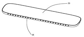
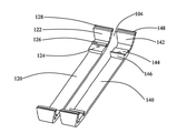
도 1은 본 발명의 일 실시예의 플렉서블 장치의 입체도이다.
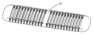
도 2는 도 1의 플렉서블 장치의 거꾸로 놓인 도면이다.
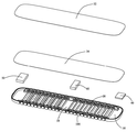
도 3은 도 1의 플렉서블 장치의 부분 분해도이다.
도 4는 도 1의 플렉서블 장치가 밴드로 변형된 개략도이고, 여기서 기능 소자는 제거되었다.
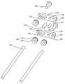
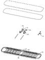
도 5는 도 3의 플렉서블 장치의 진일보한 분해도이다.
도 6은 도 5의 플렉서블 장치의 부분 확대도이다.
도 7은 도 5의 플렉서블 장치의 다른 하나의 부분 확대도이다.
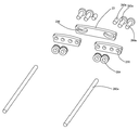
도 8은 도 1의 플렉서블 장치의 다른 하나의 부분 분해도이다.
도 9는 도 8의 플렉서블 장치의 부분 확대도이다.
도 10은 도 8의 플렉서블 장치의 다른 하나의 부분 확대도이다.
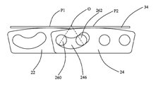
도 11은 도 1의 플렉서블 장치의 제1 가동 부재 및 제2 가동 부재의 제1 상태 모식도이다.
도 12는 도 1의 플렉서블 장치의 제1 가동 부재 및 제2 가동 부재의 제2 상태 모식도이다.
도 13-15는 도 11-12의 제1 가동 부재 및 제2 가동 부재의 상태 전환의 원리 개략도이다.
도 16은 도 1의 플렉서블 장치의 단면도이다.
도 17은 도 16의 플렉서블 장치의 부분 확대도이다.
도 18은 도 4의 플렉서블 장치의 단면도이다.BRIEF DESCRIPTION OF THE DRAWINGS The above and other aspects of the present invention will become more apparent by describing in detail exemplary embodiments thereof with reference to the attached drawings in which: It is evident that one of ordinary skill in the art will be able to acquire other obvious variations in accordance with these drawings without prejudice to creative endeavor.
1 is a perspective view of a flexible device according to an embodiment of the present invention.
Figure 2 is an inverted view of the flexible device of Figure 1;
3 is a partially exploded view of the flexible device of Fig.
Fig. 4 is a schematic view of the flexible device of Fig. 1 modified to a band, where the functional device has been removed.
Fig. 5 is an exploded view of the flexible apparatus of Fig. 3; Fig.
6 is a partial enlarged view of the flexible device of Fig.
7 is a partial enlarged view of another of the flexible apparatus of Fig.
8 is a partial exploded view of another of the flexible apparatus of Fig.
9 is a partially enlarged view of the flexible device of Fig.
10 is a partial enlarged view of another of the flexible apparatus of Fig.
Fig. 11 is a first state schematic diagram of the first movable member and the second movable member of the flexible device of Fig. 1; Fig.
Fig. 12 is a second state schematic diagram of the first movable member and the second movable member of the flexible apparatus of Fig. 1;
Figs. 13-15 are schematic diagrams of the principle of state transition of the first movable member and the second movable member of Figs. 11-12;
16 is a cross-sectional view of the flexible device of Fig.
17 is a partially enlarged view of the flexible apparatus of Fig.
18 is a cross-sectional view of the flexible device of Fig.
아래 본 발명의 실시예에서의 도면을 결합하여, 본 발명의 실시예에서의 기술적 수단을 명확하고 완전하게 설명하기로 한다.BRIEF DESCRIPTION OF THE DRAWINGS The accompanying drawings, which are incorporated in and constitute a part of the specification, illustrate embodiments of the invention and, together with the description, serve to explain the principles of the invention.
도 1 내지 도 3을 참조하면, 본 발명의 실시예의 플렉서블 장치를 나타낸다. 플렉서블 장치는 셸(10), 셸(10)내에 장착된 플렉서블 어샘블리(20) 및 셸(10)에 설치된 기능 소자(30)를 포함한다. 플렉서블 어샘블리(20)는 변형이 일어날 수 있고, 더 나아가 플렉서블 장치를 움직이게 하여 변형이 일어나도록 함으로써, 플렉서블 장치가 다른 경우의 응용 수요에 적응되게 한다.1 to 3, a flexible apparatus according to an embodiment of the present invention is shown. The flexible device includes a
도 4를 함께 참조하면, 플렉서블 장치가 일어나는 변형은 바람직하게 평판의 형태로부터 원환의 형태로 변한다. 평판의 형태일 경우, 플렉서블 장치의 전체가 펼쳐짐으로써, 사용자가 조작하는 것이 편리하게 한다. 원환의 형태일 경우, 플렉서블 장치의 전체가 구부러져 착용 가능한 장치를 형성하여, 사용자가 몸에 착용하는데 편리하도록 한다. 물론, 플렉서블 장치의 변형이 전환되는 형태는 수요에 따라 변화되어, 더 많은 응용 경우의 수요에 적응될 수도 있다. 예를 들면 아치형으로부터 원환형으로 전환되고, 평판형으로부터 파도모양으로 전환되며, U형으로부터 S형으로 전환되는 등이 있다.With reference to FIG. 4, the deformation in which the flexible device takes place preferably changes from a plate shape to a torus shape. In the form of a flat plate, the whole of the flexible device is unfolded, which makes it convenient for the user to operate. In the form of a torus, the entire flexible device is bent to form a wearable device so that it is convenient for a user to wear on the body. Of course, the manner in which the transformations of the flexible device are switched may vary according to demand, and may be adapted to the demands of more applications. For example, from an arched shape to an annular shape, from a planar shape to a wave shape, and from a U shape to an S shape.
도 5 내지 도 7을 함께 참조하면, 플렉서블 어샘블리(20)는 셸(10)의 대향하는 양측에 각각 위치하는 가동 부재(200)를 포함한다. 매 측 마다의 가동 부재(200)는 모두 제1 가동 부재(22) 및 제1 가동 부재(22)에 가동적으로 연결된 제2 가동 부재(24)를 포함한다. 제1 가동 부재(22) 및 제2 가동 부재(24)의 수량은 모두 여러개이고, 셸(10)의 대향하는 양측에 모두 분포된다. 바꾸어 말하자면, 셸(10)의 매 측 마다에는 모두 여러개의 제1 가동 부재(22) 및 제2 가동 부재(24)를 구비하고, 여기서 제1 가동 부재(22)는 제2 가동 부재(24)보다보다 셸(10)의 외측에 더 접근된다. 셸(10)의 매 측 마다의 제1 가동 부재(22)는 모두 가지런하여 선형 배열을 나타내고, 셸(10)의 매 측 마다의 제2 가동 부재(24)는 모두 가지런하여 선형 배열을 나타낸다. 셸(10)의 매 측 마다의 제1 가동 부재(22)는 서로 인접한 제1 가동 부재(22)에 모두 직접 연결되지 않고, 셸(10)의 매 측 마다의 제2 가동 부재(24)도 서로 인접한 제2 가동 부재(24)에 모두 직접 연결되지 않는다. 셸(10)의 같은 측에 위치하는 제1 가동 부재(22)는 서로 인접한 제2 가동 부재(24)와 부분적으로 겹쳐지게 연결된다. 특히, 각 제1 가동 부재(22)는 2개의 서로 인접한 제2 가동 부재(24)와 모두 나란히 배열되고 부분적으로 겹쳐지게 연결된다.5 to 7, the
제1 가동 부재(22)는 제2 가동 부재(24)와 형상 및 구조가 같다. 본 실시예에서, 제1 가동 부재(22)와 제2 가동 부재(24)는 모두 힌지(hinge)이다. 제1 가동 부재(22)는 대체로 제형을 나타내고, 그는 평탄한 바닥면(220), 경사진 측면(222) 및 만곡된 윗면(224)(top surface)을 포함한다. 제1 가동 부재(22)의 바닥면(220)은 평면이고, 그는 변형되지 않은 기능 소자(30)에 평행된다. 제1 가동 부재(22)는 2개의 측면(222)을 구비하고, 각 측면(222)은 모두 평면이며, 바닥면(220)에 상대하여 경사진다. 각 측면(222)과 바닥면(220) 사이에 끼인 내각은 둔각이다. 둔각은 90도보다 크고 180도보다 작으며, 바람직하게, 둔각은 100도보다 크고 110도보다 작다. 2개의 측면(222)은 위로 향하고 상반되는 방향을 향해 연장되어, 바닥면(220) 및 윗면(224)을 연결한다. 제1 가동 부재(22)의 윗면(224)은 원호형의 아치형 면이고, 이는 제1 가동 부재(22)의 지지면을 형성한다. 윗면(224)의 높이는 대향하는 양단으로부터 중부를 향해 점차 커져, 볼록면을 형성한다. 이해 할 수 있는 바로는, 윗면(224)은 기타 유형의 볼록면일 수도 있는 바, 예를 들면 육면체의 절반의 형상을 구비한 볼록면(볼록면은 제형에 유사함), 팔면체의 절반 형상을 구비한 볼록면(볼록면은 제형 아래에 직사각형을 추가한 것에 유사함), 십면체의 절반 형상을 구비한 볼록면 등등 이다. 호면의 대향하는 양단점과 호면이 있는 원의 원심을 연결하고, 양단점과 원심의 연결된 선의 협각을 호면의 크로싱 각도(crossing angle)로 정의한다. 윗면(224)의 크로싱 각도는 10도보다 크고 30도보다 작다.The first movable member (22) has the same shape and structure as the second movable member (24). In this embodiment, both the first
제1 가동 부재(22)에는 위치 한정 그루브(226)가 형성되어 있다. 위치 한정 그루브(226)는 제1 가동 부재(22)의 앞면(즉 제1 가동 부재(22)의 내면) 및 뒷면(즉 제1 가동 부재(22)의 외면)을 관통하고, 제1 가동 부재(22)의 일측 측면(222)에 접근된다. 위치 한정 그루브(226)는 원호형이고, 그의 만곡된 방향은 윗면(224)의 만곡 방향과 상반된다. 위치 한정 그루브(226)의 높이는 대향하는 양단으로부터 중부를 향해 점차 작아진다. 위치 한정 그루브(226)는 제1 호면, 제2 호면, 및 제1 호면과 제2 호면을 연결하는 2개의 연결 호면을 포함한다. 제1 호면은 제2 호면과 평행되고 원심을 공유한다. 제1 호면의 길이는 제2 호면의 길이보다 짧다. 연결 호면은 대체로 반원형을 나타내어, 위치 한정 그루브(226)의 대향하는 양단은 라운드 코너(round conner)를 형성한다. 위치 한정 그루브(226)의 크로싱 각도는 윗면(224)의 크로싱 각도보다 큰 바, 바람직하게, 위치 한정 그루브(226)의 크로싱 각도는 70도보다 크고 90도보다 작다.The first
제1 가동 부재(22)에는 또 위치 한정 구멍(228)이 더 형성되어 있다. 위치 한정 구멍(228)도 제1 가동 부재(22)의 앞면 및 뒷면을 관통한다. 본 실시예에서, 위치 한정 구멍(228)은 제1 위치 한정 구멍 및 제2 위치 한정 구멍을 포함한다. 제1 위치 한정 구멍은 제1 가동 부재(22)의 중부에 접근되고, 제2 위치 한정 구멍은 제1 가동 부재(22)의 타측 측면(222)에 접근된다. 위치 한정 구멍(228)의 높이는 위치 한정 그루브(226)의 최저점의 높이보다 크고 위치 한정 그루브(226)의 최고점의 높이보다 작다.The first
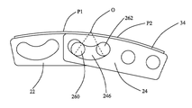
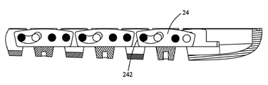
제2 가동 부재(24)는 구성 및 형상이 모두 제1 가동 부재(22)와 같다. 따라서, 제2 가동 부재(24)가 포함하는 각 소자 명칭, 각 소자 사이즈 , 각 소자 위치 관계 등은 모두 제1 가동 부재(22)를 참고할 수 있다. 제2 가동 부재(24)는 대체로 제형을 나타내고, 그는 평탄한 바닥면(240), 경사진 측면(242) 및 만곡된 윗면(244)을 포함한다. 제2 가동 부재(24)의 바닥면(240)은 평면이고, 그는 변형되지 않은 기능 소자(30)에 평행된다. 제2 가동 부재(24)는 2개의 측면(242)을 구비하고, 각 측면(242)은 모두 평면이며, 바닥면(240)에 상대하여 경사진다. 각 측면(242)과 바닥면(240) 사이에 끼인 내각은 둔각이다. 둔각은 90도보다 크고 180도보다 작으며, 바람직하게, 둔각은 100도보다 크고 110도보다 작다. 2개의 측면(242)은 위로 향하고 상반되는 방향을 향해 연장되어, 바닥면(240) 및 윗면(244)을 연결한다. 제2 가동 부재(24)의 윗면(244)은 원호형의 아치형 면이고, 이는 제2 가동 부재(24)의 지지면을 형성한다. 윗면(244)의 높이는 대향하는 양단으로부터 중부를 향해 점차 커져, 볼록면을 형성한다. 윗면(244)의 크로싱 각도는 10도보다 크고 30도보다 작다. 이해 할 수 있는 바로는, 윗면(244)은 기타 유형의 볼록면일 수도 있고, 예를 들면 육면체의 절반 형상을 구비한 볼록면, 팔면체의 절반 형상을 구비한 볼록면, 십면체의 절반 형상을 구비한 볼록면 등등 이다.The configuration and shape of the second
제2 가동 부재(24)에는 위치 한정 그루브(246)가 형성되어 있다. 위치 한정 그루브(246)는 제2 가동 부재(24)의 앞면(즉 제2 가동 부재(24)의 내면) 및 뒷면(즉 제2 가동 부재(24)의 외면)을 관통하고, 제2 가동 부재(24)의 일측 측면(242)에 접근된다. 위치 한정 그루브(246)는 원호형이고, 그의 만곡된 방향은 윗면(244)의 만곡 방향과 상반된다. 위치 한정 그루브(246)의 높이는 대향하는 양단으로부터 중부를 향해 점차 작아진다. 위치 한정 그루브(246)는 제1 호면, 제2 호면, 및 제1 호면과 제2 호면을 연결하는 2개의 연결 호면을 포함한다. 제1 호면은 제2 호면과 평행되고 원심을 공유한다. 제1 호면의의 길이는 제2 호면의 길이보다 짧다. 연결 호면은 대체로 반원형을 나타내어, 위치 한정 그루브(246)의 대향하는 양단은 라운드 코너를 형성한다. 위치 한정 그루브(246)의 크로싱 각도는 윗면(244)의 크로싱 각도보다 큰 바, 바람직하게, 위치 한정 그루브(246)의 크로싱 각도는 70도보다 크고 90도보다 작다.The second
제2 가동 부재(24)에는 또 위치 한정 구멍(248)이 더 형성되어 있다. 위치 한정 구멍(248)도 제2 가동 부재(24)의 앞면 및 뒷면을 관통한다. 본 실시예에서, 위치 한정 구멍(248)은 제1 위치 한정 구멍 및 제2 위치 한정 구멍을 포함한다. 제1 위치 한정 구멍은 제2 가동 부재(24)의 중부에 접근되고, 제2 위치 한정 구멍은 제2 가동 부재(24)의 타측 측면(242)에 접근된다. 위치 한정 구멍(248)의 높이는 위치 한정 그루브(246)의 최저점의 높이보다 크고 위치 한정 그루브(246)의 최고점의 높이보다 작다.The second
플렉서블 어샘블리(20)는 가동 부재(200)와 연결된 위치 한정 부재(202)를 더 포함한다. 특히, 제1 가동 부재(22)는 서로 인접된 제2 가동 부재(24)와 위치 한정 부재(202)를 통해 부분적으로 겹쳐지게 연결되고, 여기서 제1 가동 부재(22)의 앞면의 일부분이 제2 가동 부재(24)의 뒷면의 일부분과 접촉된다. 위치 한정 부재(202)는 위치 한정 그루브(226, 246) 내에서 슬라이딩함으로써, 제1 가동 부재(22)가 제2 가동 부재(24)에 상대하여 움직이게 한다. 본 실시예에서, 위치 한정 부재(202)는 제1 위치 한정 부재(26) 및 제2 위치 한정 부재(28)를 포함한다. 제2 위치 한정 부재(28)는 제1 가동 부재(22)을 서로 인접된 하나의 제2 가동 부재(24)와 연결하기 위한 것이고, 제1 위치 한정 부재(26)는 제1 가동 부재(22)를 다른 하나의 서로 인접된 제2 가동 부재(24)과 연결하기 위한 것이다. 제2 위치 한정 부재(28)와 제1 위치 한정 부재(26)의 구성은 같을 수 있고, 다를 수도 있다. 본 실시예에서, 제2 위치 한정 부재(28)와 제1 위치 한정 부재(26)는 모두 제1 위치 한정 축(280, 260) 및 제2 위치 한정 축(282, 262)을 포함한다. 제2 위치 한정 부재(28)의 제1 위치 한정 축(280) 및 제2 위치 한정 축(282)은 먼저 제1 가동 부재(22)의 위치 한정 그루브(226)를 관통하고 다시 서로 인접된 하나의 제2 가동 부재(24)의 2개의 위치 한정 구멍(248) 내에 각각 관입되며; 제1 위치 한정 부재(26)의 제1 위치 한정 축(260) 및 제2 위치 한정 축(262)은 먼저 제1 가동 부재(22)의 2개의 위치 한정 구멍(228)을 관통하고 다시 서로 인접된 다른 하나의 제2 가동 부재(24)의 위치 한정 그루브(246) 내에 관입된다. 제1 위치 한정 부재(26)의 제1 위치 한정 축(260) 및 제2 위치 한정 축(262)은 서로 이격되고, 양자 사이의 간격은 플렉서블 어샘블리(20)가 변형될 경우 변하지 않고 유지되며; 제2 위치 한정 부재(28)의 제1 위치 한정 축(280) 및 제2 위치 한정 축(282)은 서로 이격되고, 양자 사의의 간격도 플렉서블 어샘블리(20)가 변형될 경우 변하지 않고 유지된다. The
제2 위치 한정 부재(28)의 제1 위치 한정 축(280)은 제2 위치 한정 축(282)의 구성과 같을 수 있고, 다를 수도 있으며; 제1 위치 한정 부재(26)의 제1 위치 한정 축(260)은 제2 위치 한정 축(262)의 구성과 같을 수 있고, 다를 수도 있다. 제2 위치 한정 부재(28)의 제1 위치 한정 축(280)은 제1 위치 한정 부재(26)의 제1 위치 한정 축(260) 또는 제2 위치 한정 축(262)의 구성과 같고, 다를 수도 있으며; 제2 위치 한정 부재(28)의 제2 위치 한정 축(282)은 제1 위치 한정 부재(26)의 제1 위치 한정 축(260) 또는 제2 위치 한정 축(262)의 구성과 같을 수 있고, 다를 수도 있다. 본 실시예에서, 제2 위치 한정 부재(28)의 제1 위치 한정 축(280), 제2 위치 한정 축(282) 및 제1 위치 한정 부재(26)의 제1 위치 한정 축(260), 제2 위치 한정 축(262)의 구성은 모두 같지 않다. 제2 위치 한정 부재(28)의 제2 위치 한정 축(282), 제2 위치 한정 부재(28)의 제1 위치 한정 축(280), 제1 위치 한정 부재(26)의 제1 위치 한정 축(260), 제1 위치 한정 부재(26)의 제2 위치 한정 축(262)의 길이는 순차적으로 작아진다. 제2 위치 한정 부재(28)의 제1 위치 한정 축(280)은 나사를 포함하고, 그는 너트 캡 및 너트 캡으로부터 수직으로 연장된 스크류(screw)로 구성된다. 스크류는 제1 가동 부재(22)의 위치 한정 그루브(226)를 관통하고 서로 인접한 하나의 제2 가동 부재(24)의 하나의 위치 한정 구멍(248)내에 관입된다. 너트 캡(nut cap)은 제1 가동 부재(22)의 뒤측면에 맞닿아 접촉되어 제1 위치 한정 축(280)이 빠지는 것을 방지한다. 제2 위치 한정 부재(28)의 제2 위치 한정 축(282)은 연속된 연결 로드(rod)를 포함하고, 그는 하나의 세로 길이의 로드 모양의 구성이다. 연결 로드는 플렉서블 장치 일측의 제1 가동 부재(22)의 위치 한정 그루브(226) 및 서로 인접한 하나의 제2 가동 부재(24)의 다른 하나의 위치 한정 구멍(248)를 관통하고, 플렉서블 장치의 대향하는 타측의 하나의 제2 가동 부재(24)의 위치 한정 구멍(248)을 관통한 후 서로 인접한 하나의 제1 가동 부재(22)의 위치 한정 그루브(226)내에 다시 관입된다. 이로부터, 연결 로드는 플렉서블 장치의 대향하는 양측에 위치하는 가동 부재(200)를 연결하고, 특히 일측 가동 부재(200)의 제1 가동 부재(22) 및 제2 가동 부재(24)를 타측 가동 부재(200)의 제1 가동 부재(22) 및 제2 가동 부재(24)와 연결하여, 플렉서블 장치를 단단하게 하는 역할을 한다. 제1 위치 한정 부재(26)의 제1 위치 한정 축(260)은 스크류를 포함하고, 그는 제1 가동 부재(22)의 하나의 천공(228)을 관통하고 서로 인접한 다른 하나의 제2 가동 부재(24)의 위치 한정 그루브(246)내에 관입된다. 제1 위치 한정 부재(26)의 제2 위치 한정 축(262)은 볼록 기둥을 포함하고, 그는 제1 가동 부재(22)의 다른 하나의 천공(228)를 관통하고 서로 인접한 다른 하나의 제2 가동 부재(24)의 위치 한정 그루브(246)내에 관입된다. 제2 위치 한정 부재(28)의 제1 위치 한정 축(280)은 플렉서블 장치의 일측 제1 가동 부재(22)를 서로 인접한 하나의 제2 가동 부재(24)와 연결하고; 제2 위치 한정 부재(28)의 제2 위치 한정 축(282)은 플렉서블 장치 일측의 제1 가동 부재(22), 서로 인접한 하나의 제2 가동 부재(24)와 플렉서블 장치 타측의 제1 가동 부재(22), 서로 인접한 하나의 제2 가동 부재(24)를 연결하며; 제1 위치 한정 부재(26)의 제1 위치 한정 축(260)은 플렉서블 장치 일측 제1 가동 부재(22)를 서로 인접한 다른 하나의 제2 가동 부재(24)와 연결하고; 제1 위치 한정 부재(26)의 제2 위치 한정 축(262)은 플렉서블 장치 일측의 제1 가동 부재(22)를 서로 인접한 다른 하나의 제2 가동 부재(24)와 연결한다. 제1 위치 한정 축(260, 280), 제2 위치 한정 축(262, 282)의 직경은 위치 한정 그루브(226, 246)의 폭과보다 같거나 또는 약간 작음으로써, 위치 한정 그루브(226, 246)내에 긴밀히 매치될 수 있다. 제1 가동 부재(26) 또는 제2 가동 부재(28)의 제1 위치 한정 축(260, 280)과 제2 위치 한정 축(262, 282) 사이의 거리는 위치 한정 그루브(226, 246)의 길이보다 짧음으로써, 제1 위치 한정 축(260, 280) 및 제2 위치 한정 축(262, 282)이 위치 한정 그루브(226, 246)내에서 슬라이딩할 수 있도록 하고, 더 나아가 제1 가동 부재(22)를 움직이게 하여 제2 가동 부재(24)에 상대하여 이동하도록 한다.The first
플렉서블 어샘블리(20)는 가동 부재(200)에 맞닿은 위치 제한 부재(204)를 더 포함하고, 위치 제한 부재(204)는 위치 한정 부재(202)에 가동적으로 씌움 설치되어 가동 부재(200)에 인가되는 힘의 세기를 제어하여, 플렉서블 어샘블리(20)가 변형될 경우의 완충(damping)을 조절한다. 특히, 제2 위치 한정 부재(28) 및 제1 위치 한정 부재(26)의 제1 위치 한정 축(280, 260)은 위치 한정 그루브(226, 246)를 관통하여 나온 후 모두 위치 제한 부재(204)와 잠금 고정된다. 본 실시예에서, 위치 제한 부재(204)는 탄성편(272)을 구비한 너트(270)이고, 그는 나사산을 통해 제1 위치 한정 축(260, 280)의 나사산과 조여져 결합된다. 탄성편(272)은 너트(270)와 제1 가동 부재(22) 또는 제2 가동 부재(24)의 앞면 사이에 끼워서 설치되고 탄성적으로 맞닿아 압력을 준다. 또한, 위치 제한 부재(204)와 제1 위치 한정 축(260, 280)이 단단히 조여지는 정도를 조절하는 것을 통해, 탄성편(272)이 제1 가동 부재(22) 또는 제2 가동 부재(24)에 인가하는 탄력을 조절할 수 있음으로써, 플렉서블 어샘블리(20)가 회전할 경우의 완충을 제어한다. 완충이 적절한 수치까지 조절될 경우, 플렉서블 어샘블리(20)는 회전될 경우 임의의 위치에 위치를 정할 수 있음으로써, 더 많은 형상 수요에 적응될 수 있다.The
기능 소자(30)가 예컨대 플렉서블 터치스크린, 플렉서블 디스플레이 스크린 또는 양자가 겸유된 플렉서블 기능성 스크린(32)을 포함할 경우, 재료 자체의 특성으로 인해, 플렉서블 기능성 스크린(32)이 스트레칭 또는 압축에 견디지 못하는 것을 초래한다. 플렉서블 기능성 스크린(32)이 플렉서블 장치가 변형될 경우 스트레칭 또는 압축이 일어나는 것을 줄이거나 심지어 방지하기 위해, 본 발명은 제1 가동 부재(22)와 제2 가동 부재(24)의 구성 및 연결 관계에 대해 더 개선한다.If the
도 11 내지 도 12을 함께 참조하면, 플렉서블 터치스크린 또는 플렉서블 디스플레이 스크린은 모두 플렉서블 재질이기에, 조작 또는 관람을 편리하게 하기 위해, 기능 소자(30)는 플렉서블 터치스크린 또는 플렉서블 디스플레이 스크린의 하방에 고정된 지지판(34)을 더 포함한다. 지지판(34)의 면적 및 형상은 플렉서블 기능성 스크린(32)과 같다. 지지판(34)은 경도가 비교적 높은 탄성 재료로 제조되는 바, 예를 들면 강판, 철판, 동판등이다. 지지판(34)의 경도는 플렉서블 기능성 스크린(32)의 경도보다 높다. 지지판(34)은 제1 가동 부재(22) 및 제2 가동 부재(24)에 고정된다. 바람직하게, 지지판(34)은 제1 가동 부재(22) 및 제2 가동 부재(24)의 지지면(즉 윗면(224, 244))에 고정된다. 지지면은 볼록한 호면이기에, 따라서 지지판(34)은 지지면의 윗부분에 고정되는 바, 즉 지지면의 고정점이 바로 그의 윗부분이다. 물론, 만약 제1 가동 부재(22) 및 제2 가동 부재(24)의 윗면(224, 244)이 기타 형상일 경우, 고정점은 제1 가동 부재(22) 및 제2 가동 부재(24)의 윗면(224, 244)의 기타 위치점에 위치할 수도 있어, 윗부분의 위치에만 한정되지 않는다. 나아가, 고정점은 단지 정의한 소자의 명칭을 설명하기 위한 것일 뿐인 바, 그의 실질은 윗면(224, 244)의 윗부분이 하나의 구역을 포함할 수 있는 것을 가리키며, 어떠한 단독의 점에 한정되는 것이 아니다. 지지판(34)은 플렉서블 장치의 매 측 마다의 각 제1 가동 부재(22)와 제2 가동 부재(24)의 윗면(224, 244)의 윗부분에 고정되고, 지지판(34)은 제1 가동 부재(22) 및 제2 가동 부재(24)의 윗면(224, 244)의 기타 위치와 이격된다. 지지판(34)은 용접, 접착 등 방식을 통해 제1 가동 부재(22) 및 제2 가동 부재(24)에 고정될 수 있다.11 to 12, since the flexible touch screen or the flexible display screen are all flexible materials, in order to facilitate manipulation or viewing, the
제2 가동 부재(24)의 위치 한정 그루브(246)는 원호형이기에, 제2 가동 부재(24)가 제1 가동 부재(22)에 상대하여 이동할 경우, 제2 가동 부재(24)의 위치 한정 그루브(246)는 제1 가동 부재(22)와 제2 가동 부재(24)의 제1 위치 한정 부재(26)를 연결한 제1 위치 한정 축(260) 및 제2 위치 한정 축(262)의 위치 제한을 받음으로써, 제2 가동 부재(24)가 위치 한정 그루브(246)의 궤적을 따라 이동하게 된다. 구체적으로 말하자면, 제2 가동 부재(24)가 제1 가동 부재(22)에 상대하여 회전되는 동시에, 또 제1 가동 부재(22)에 상대하여 평행 이동하는 바, 즉 제2 가동 부재(24)는 제1 가동 부재(22)에 상대하여 이동하는 동시에 회전과 평행 이동인 2개의 운동 분량을 포함한다. 제2 가동 부재(24)의 회전 방향은 제1 가동 부재(22)에 상대하여 시곗바늘 방향으로 회전하고, 제2 가동 부재(24)의 평행 이동 방향은 제1 가동 부재(22)의 위치 한정 그루브(226) 를 향해 평행 이동하는 방향이다.Since the
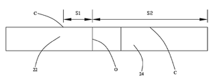
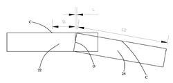
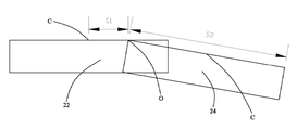
나아가, 제2 가동 부재(24)의 위치 한정 그루브(246)가 원호형이기에, 이에 따라 대응되는 원심을 구비한다. 상기 원심이 바로 제2 가동 부재(24)의 회전 원심(O)이기도 하다. 본 실시예에서 말하는 회전 원심에서, 어느 하나의 소자가 당해 회전 원심을 에워싸고 회전할 경우, 당해 소자의 임의의 위치에서 원심까지의 거리는 변하지 않는다. 제2 가동 부재(24)가 그의 회전 원심(O)을 에워싸고 이동한 궤적의 만곡 방향도 제2 가동 부재(24)의 윗면(244)의 만곡 방향과 상반된다. 본 실시예에서, 제2 가동 부재(24)의 회전 원심(O)은 제2 가동 부재(24)의 두께 중심보다 높다. 특히, 제2 가동 부재(24)의 회전 원심(O)은 제2 가동 부재(24)의 지지면의 윗부분과 가지런하거나 또는 제2 가동 부재(24)보다 높다. 제2 가동 부재(24)의 회전 원심(O)이 제2 가동 부재(24)의 두께 중심보다 높기에, 제2 가동 부재(24)가 회전 원심(O)을 에워싸고 회전할 경우, 제2 가동 부재(24)의 두께 원인으로 인하여 발생하는 길이차이를 줄일 수 있다. 도 13 내지 도 15에 도시된 바와 같이, 설명을 간소화하기 위해, 제1 가동 부재(22) 및 제2 가동 부재(24)을 모두 직사각형체로 설정한다. 직사각형체의 윗면 중심(C)은 제1 가동 부재(22) 및 제2 가동 부재(24)의 고정점이다. 제1 가동 부재(22)의 윗면 중심(C)에서 제2 가동 부재(24)의 근접된 말단까지의 거리는 S1이고, 제2 가동 부재(24)의 제1 가동 부재(22)에 접근한 말단에서 제2 가동 부재의 윗면 중심(C)까지의 거리는 S2이다. 만일 제2 가동 부재(24)의 회전 원심(O)이 제2 가동 부재(24)의 두께 중심과 높이가 같을 경우, 도 13에 도시된 바와 같이, 제2 가동 부재(24)에 회전이 발생하지 않을 경우, 제1 가동 부재(22)와 제2 가동 부재(24)의 윗면 중심(C)의 간격은 S1+S2이다. 도 14에 도시된 바와 같이, 제2 가동 부재(24)가 회전 원심(O)을 에워싸고 회전할 경우, 회전 원심(O)이 제2 가동 부재(24)의 윗면보다 낮기에, 제2 가동 부재(24)의 윗면의 말단을 근접한 곳은 회전하기 전의 위치에 상대하여 제1 가동 부재(22)의 윗면에 변위(L)가 발생되는 것을 초래한다. 이런 상황에서, 제1 가동 부재(22)와 제2 가동 부재(24)의 윗면을 따라, 제1 가동 부재(22)의 윗면 중심(C)에서 제2 가동 부재(24)의 윗면 중심(C)까지의 길이는 S1+S2+L이다. L의 존재로 인해, 제1 가동 부재(22) 및 제2 가동 부재(24)의 윗면을 따른 윗면 중심(C) 사이의 거리는 길이차이가 출현하는 것을 초래하는 것은 명확한 것이다. 도 15에 도시된 바와 같이, 만일 제2 가동 부재(24)의 회전 원심(O)이 제2 가동 부재(24)의 윗면과 가지런하면 제2 가동 부재(24)가 회전 원심(O)을 에워싸고 회전할 경우, 회전 원심(O)이 제2 가동 부재(24)의 윗면과 가지런하기에, 제1 가동 부재(22)의 윗면 중심(C)이 제1 가동 부재(22) 및 제2 가동 부재(24)의 윗면을 따른 제2 가동 부재(24)의 윗면 중심(C)까지의 거리는 S1+S2를 시종 유지함으로써, 길이차이가 출현하는 것을 피한다. 이로부터 볼 수 있듯이, 제2 가동 부재(24)의 두께 방향을 따라, 제2 가동 부재(24)의 두께 중심으로부터 제2 가동 부재(24)의 윗면까지, 제2 가동 부재(24)의 회전 원심(O)이 높을 수록, 출현하는 길이차이가 더 짧아진다.Further, since the position-defining
이와 반대로, 출현하는 길이차이가 클수록, 제1 가동 부재(22)의 윗면 중심(C)으로부터 제1 가동 부재(22)의 윗면 및 제2 가동 부재(24)의 윗면을 따른 제2 가동 부재(24)의 윗면 중심(C)까지의 거리가 길어지는 것을 나타낸다. 지지판(34)이 제1 가동 부재(22)의 고정점(즉 윗면 중심(C)) 및 제2 가동 부재(24)의 고정점(즉 윗면 중심(C))에 동시에 고정되기에, 제1 가동 부재(22)의 고정점으로부터 제1 가동 부재(22)의 윗면 및 제2 가동 부재(24)의 윗면을 따른 제2 가동 부재(24)의 고정점까지의 거리가 길어질 경우, 지지판(34)이 2개의 고정점 사이에서의 거리도 반드시 이에 따라 길어지는 것을 의미함으로써, 지지판(34)이 2개의 고정점 사이에서 스트레칭되어 변형이 출현되도록 한다.Conversely, the greater the difference in emergence length, the larger the distance between the upper surface center C of the first
상술한 원리에 기반하여, 지지판(34)이 2개의 고정점 사이에서 출현하는 스트레칭 현상을 작아지게 하거나 또는 방지하기 위해, 본 실시예는 제2 가동 부재(24)의 회전 원심(O)을 제2 가동 부재(24)의 두께 중심보다 높게 설치하고, 특히 제2 가동 부재(24)의 고정점과 높이가 일치하도록 한다. 물론, 회전 원심(O)은 지지판(34)에 위치할 수도 있는 바, 특히 지지판(34)의 윗면에 위치할 수도 있다.In order to reduce or prevent the stretching phenomenon in which the
나아가, 본 실시예의 제1 가동 부재(22) 및 제2 가동 부재(24)의 윗면(224, 244)은 모두 원호면(arc surface)이고, 제2 가동 부재(24)가 제1 가동 부재(22)를 에워싸고 회전한 후, 제2 가동 부재(24)와 제1 가동 부재(22)의 윗면(224, 244)은 공동으로 연속적인 원호면을 형성함으로써, 완전한 플렉서블 장치가 원환을 형성하도록 한다. 또한, 제1 가동 부재(22) 및 제2 가동 부재(24)의 윗면(224, 244)은 윗면(224, 244)에 수직되는 평면내의 투영에 연속된 원호를 공동으로 형성한다. 따라서, 지지판(34)이 제1 가동 부재(22)와 제2 가동 부재(24)의 2개의 고정점 사이의 부분도 반드시 제1 가동 부재(22) 및 제2 가동 부재(24)의 윗면(224, 244)과 일치한 원호형으로 벤딩되어야, 제2 가동 부재(24)가 제1 가동 부재(22)에 상대하여 이동한 후, 지지판(34)이 제1 가동 부재(22) 및 제2 가동 부재(24)로 구성된 연속된 원호면에 긴밀하게 접착될 수 있는 것을 확보할 수 있다. 원호의 길이가 직선 거리보다 길기에, 특히 제1 가동 부재(22)와 제2 가동 부재(24)의 2개의 고정점과 제2 가동 부재의 회전 원심(O)(회전 원심(O)이 제1 가동 부재(22)의 윗면(224)에 위치하게 설정)이 공동으로 정의하는 원호의 길이가, 제1 가동 부재(22)의 고정점에서 제2 가동 부재(24)의 회전 원심(O)까지의 직선 길이와 제2 가동 부재(24)의 고정점에서 제2 가동 부재(24)의 회전 원심(O)까지의 직선 길이의 합보다 길다. 만약 바로 잡지 않으면, 원호를 직선과 비교한 길이차이가 또한 지지판(34)이 스트레칭되는 상황이 출현되는 것을 초래할 수 있다. 따라서, 실제로는 제2 가동 부재(24)의 회전 원심(O)을 마땅히 더 조정하여 원호를 직선과 비교하여 발생하는 길이차이를 작아지게 하거나 또는 상쇄하여야 한다. 도 11 내지 도 12를 참조하면, 바람직하게, 제2 가동 부재(24)의 회전 원심(O)은 마땅히 지지판(34)의 윗면보다 높아, 제2 가동 부재(24)가 회전 원심(O)을 에워싸고 회전할 경우 진일보하여 제1 가동 부재(22)를 향해 평행 이동 하도록 하고, 더 나아가 원호를 직선과 비교하여 발생하는 길이차이를 작아지게 하거나 또는 상쇄한다. 제2 가동 부재(24)의 회전 원심(O)에서 지지판(34)의 윗면까지의 거리와 지지판(34)의 두께 비율은 0.1 내지 0.5 사이에 있다. 회전 원심(O)은 지지판(34)의 윗면보다 높기에, 회전 원심(O)의 위치는 제1 가동 부재(22)에 상대하여 항상 일정하다. 바꾸어 말하자면, 제2 가동 부재(24)가 제1 가동 부재(22)에 상대하여 움직일 경우, 그의 회전 원심(O)은 제1 가동 부재(22)의 위치에 상대하여 변화가 일어나지 않는다. 물론, 만약 회전 원심(O)이 지지판(34)의 윗면 또는 제1 가동 부재(22)의 윗면(224)에 위치하면, 그가 제1 가동 부재(22)에 상대하는 위치도 항상 일정하다. 나아가, 회전 원심(O)은 플렉서블 기능성 스크린(32)에, 심지어 플렉서블 기능성 스크린(32)보다 높은데 위치할 수 있다. 이 외에, 제2 가동 부재(24)의 회전 원심(O)이 지지판(34)의 윗면보다 높기에, 회전 원심(O)은 플렉서블 소자(30)의 경도가 더 높은 하부(즉 지지판(34))보다 높고, 플렉서블 소자(30)의 경도가 더 낮은 상부(즉 플렉서블 기능성 스크린(32))보다 높거나 또는 가지런하다.Further, the
플렉서블 장치가 제1 상태에 처할 경우(예를 들면 평판 상태), 제2 가동 부재(24)는 제1 가동 부재(22)에 상대하여 펼쳐진다. 제2 가동 부재(24)와 제1 가동 부재(22)는 나란히 배열되고 가지런하며, 제1 위치 한정 부재(26)의 제1 위치 한정 축(260)은 제2 가동 부재(24)의 위치 한정 그루브(246)의 제1 말단에 맞닿으며, 제1 위치 한정 부재(26)의 제2 위치 한정 축(262)은 제2 가동 부재(24)의 위치 한정 그루브(246)의 제2 말단과 이격되고, 여기서 제1 말단 및 제2 말단은 각각 위치 한정 그루브(246)의 대향하는 양단에 위치한다. 플렉서블 장치가 제2 상태에 처할 경우(예를 들면 원환 상태), 제2 가동 부재(24)는 제1 가동 부재(22)에 상대하여 모아진다. 제2 가동 부재(24)는 제1 가동 부재(22)와 나란히 배열되고 협각을 형성하며, 제2 가동 부재(24)는 제1 가동 부재(22)에 상대하여 경사진다. 제1 위치 한정 부재(26)의 제1 위치 한정 축(260)은 제2 가동 부재(24)의 위치 한정 그루브(246)의 제1 말단과 이격하고, 제1 위치 한정 부재(26)의 제2 위치 한정 축(262)은 제2 가동 부재(24)의 위치 한정 그루브(246)의 제2 말단과 맞닿아 접촉된다. 같은 도리로, 제2 위치 한정 부재(28)는 다른 상태일 경우 또 제1 위치 한정 부재(26)와 비슷한 위치 관계를 구비하는 바, 여기서 더이상 중복하여 설명하지 않는다.When the flexible device is in the first state (for example, in the flat state), the second
지지판(34)이 제1 가동 부재(22) 및 제2 가동 부재(24)의 윗면(224, 226)의 윗부분에만 고정되었기에, 제1 상태일 경우, 지지판(34)의 바닥면은 제1 가동 부재(22) 및 제2 가동 부재(24)의 윗면(224, 226)의 기타 위치와 분리되고, 제2 상태일 경우, 지지판(34)의 바닥면은 제1 가동 부재(22) 및 제2 가동 부재(24)의 윗면(224, 226)의 기타 위치와 접촉된다. 지지판(34)이 제2 상태일 경우 제1 가동 부재(22)또는 제2 가동 부재(24)의 윗면(224, 226)과의 접촉 면적은 지지판(34)이 제1 상태일 경우 제1 가동 부재(22) 또는 제2 가동 부재(24)의 윗면(224, 226)과의 접촉 면적보다 크다.The
특히, 지지판(34)의 윗면이 제1 가동 부재(22)의 고정점에 대응하는 위치를 제1 참고점(P1)으로 정의하고, 지지판(34)의 윗면이 제2 가동 부재(24)의 고정점에 대응하는 위치를 제2 참고점(P2)으로 정의한다. 제2 상태일 경우 지지판(34)의 윗면이 제1 참고점(P1)에서 제2 참고점(P2) 사이의 호의 길이는 제1 상태일 경우 제1 참고점(P1)에서 제2 참고점(P2)까지의 직선 거리와 같다. 이로부터, 지지판(34)의 윗면이 플렉서블 장치가 변형될 경우 길이에 변화가 일어나지 않는 것을 확보한다.Particularly, the position of the upper surface of the
이해 할 수 있는 바로는, 제1 위치 한정 부재(26)는 제1 위치 한정 축(260)만 포함할 수도 있는 바, 이때 제1 위치 한정 부재(26)는 제1 위치 한정 축(260)이며, 상응하게, 제2 가동 부재(24)의 위치 한정 그루브(246)는 대응하여 단축되고; 제2 위치 한정 부재(28)도 제1 위치 한정 축(280)만 포함할 수 있는 바, 이때 제2 위치 한정 부재(28)는 제1 위치 한정 축(280)이며, 상응하게, 제1 가동 부재(22)의 위치 한정 그루브(226)도 대응하여 단축된다. 이러한 하나의 제1 위치 한정 축(260, 280)만 포함하는 구성은 상술한 제1 위치 한정 축(260, 280) 및 제2 위치 한정 축(262, 282)을 동시에 사용한 것과 같은 효과를 마찬가지로 구현할 수 있다. 또 이해 할 수 있는 바로는, 일부 상황에서, 위치 한정 부재(202)는 제2 위치 한정 부재(28)만 포함할 수도 있는 바, 이때 위치 한정 부재(202)는 제2 위치 한정 부재(28)이다. 상응하게, 제1 가동 부재(22)와 제2 가동 부재(24)는 층층이 배열된 양상을 띠는 바, 예를 들면 하나의 제1 가동 부재(22)가 하나의 제2 가동 부재(24)의 외측에 설치되고, 다른 하나의 제2 가동 부재(24)가 당해 제1 가동 부재(22)의 외측에 또 설치되며, 다른 하나의 제1 가동 부재(22)가 당해 다른 하나의 제2 가동 부재(24)의 외측에 설치되고, 이렇게 유추한다. 각 위치 한정 부재(24)는 상응한 제1 가동 부재(22)와 제2 가동 부재(24)의 중첩 위치를 관통한다. 이러한 상황에서 플렉서블 장치의 형태 전환 및 플렉서블 소자(30)가 스트레칭되지 않게 유지되거나 또는 플렉서블 소자(30)가 스트레칭되는 것을 줄이는 효과를 마찬가지로 구현할 수 있다. 또 이해 할 수 있는 바로는, 극단 상황에서, 플렉서블 어샘블리(20)의 매 측 마다 하나의 제1 가동 부재(22) 및 제2 가동 부재(24)만 포함할 수도 있고, 또는 한측에만 하나의 제1 가동 부재(22) 또는 제2 가동 부재(24)를 포함할 수도 있으며, 심지어 플렉서블 어샘블리(20)를 셸(10)의 중간에 설치하여, 플렉서블 어샘블리(20)가 하나의 제1 가동 부재(22) 및 제2 가동 부재(24)만을 포함하도록 할 수 있어, 여전히 플렉서블 장치의 형태 전환 및 플렉서블 소자(30)가 스트레칭되지 않게 유지되거나 또는 플렉서블 소자(30)가 스트레칭되 것을 줄이는 효과를 구현할 수 있다.As can be appreciated, the first position defining member 26 may include only the first
도 7을 함께 참조하면, 셸(10)은 여러개의 연결 부재(100)로 구성된다. 이러한 연결 부재(100)는 여러개의 제1 연결 부재(12) 및 제2 연결 부재(14)를 포함한다. 제1 연결 부재(12)는 제2 연결 부재(14)와 번갈아 설치되고 서로 이격된다. 제1 연결 부재(12) 및 제2 연결 부재(14)는 경질의 재료를 이용하여 제조할 수 있는 바, 예를 들면 플라스틱, 금속 등으로 제조되어, 셸(10) 내부의 전자 부품을 보호한다. 제1 연결 부재(12)는 제2 연결 부재(14)의 구성과 같을 수 있고 다를 수도 있다. 본 실시예에서, 제1 연결 부재(12)는 제2 연결 부재(14)의 구성과 다르다. 제1 연결 부재(12) 및 제2 연결 부재(14)는 모두 기판(120, 140) 및 기판(120, 140)의 대향하는 양단으로부터 위로 향하여 연장된 측벽(122, 142)을 포함한다. 제1 연결 부재(12) 및 제2 연결 부재(14)의 기판(120, 140)은 모두 2개의 돌출된 계단(124, 144)을 더 포함한다. 각 제1 연결 부재(12) 및 제2 연결 부재(14)의 2개의 계단(124, 144)은 각각 기판의 대향하는 양단에 접근하고, 상응한 측벽(122, 142)에 근접된다. 제1 연결 부재(12) 및 제2 연결 부재(14)는 모두 계단(124, 144)에서 돌출된 막음판(126, 146)을 더 형성한다. 막음판(126, 146)의 높이는 계단(122, 124)의 높이보다 높다. 제2 연결 부재(14)의 막음판(146)은 계단(144)의 내측에 위치하고 상응한 측벽(142)에서 멀리있고, 제1 연결 부재(12)의 막음판(126)은 계단(124)의 외측에 위치하고 상응한 측벽(122)에 접근한다. 제1 연결 부재(12) 및 제2 연결 부재(14)의 막음판(126, 146)은 모두 가장 가까운 측벽(122, 142)과 이격된다. 플렉서블 장치가 제1 상태, 제2 상태 및 제1 상태와 제2 상태 사이에 있는 기타 상태에 처할 경우, 제1 연결 부재(12)는 제2 연결 부재(14)와 이격되는 것을 시종 유지하고, 양자 사이에 개구된 홈(104)을 형성한다. 제1 연결 부재(12)와 제2 연결 부재(14)는 플렉서블 어샘블리(20)가 변형될 경우 상대적으로 이동할 수 있지만 이격되는 것을 시종 유지한다.Referring to FIG. 7 together, the
제1 연결 부재(12) 및 제2 연결 부재(14)은 각 계단(124, 144)에 모두 스크류 홀이 형성되어 있다. 각 제1 연결 부재(12)는 서로 인접한 하나의 제2 연결 부재(14)와 연결 부재 그룹을 구성하고, 각 제1 가동 부재(22) 및 서로 인접한 하나의 제2 가동 부재(24)로 구성된 가동 부재 그룹을 연결 및 지지하기 위한 것이다. 제1 연결 부재(12) 및 제2 연결 부재(14)는 나란히 배열되어 설치되고, 제1 가동 부재(22) 및 제2 가동 부재(24)는 제1 연결 부재(12) 및 제2 연결 부재(14)의 같은 측의 계단(124, 144)에 놓여진다. 제1 가동 부재(22) 및 제2 가동 부재(24)는 모두 동시에 제1 연결 부재(12) 및 제2 연결 부재(14)의 계단(124, 144)의 윗면과 맞닿아 접촉된다. 제1 가동 부재(22)는 제1 연결 부재(12)의 막음판(126)에 접근되고, 제2 가동 부재(24)는 제2 연결 부재(14)의 막음판(146)에 접근됨으로써, 부분적으로 겹쳐지게 배열된다. 제1 연결 부재(12)의 막음판(126)은 제1 가동 부재(22)의 외측면에 맞닿아 접촉되고, 제2 연결 부재(14)의 막음판(146)은 제2 가동 부재(24)의 내측면에 맞닿아 접촉됨으로써, 제1 가동 부재(12) 및 제2 가동 부재(14)를 양자 사이에 끼워 설치하여, 제1 가동 부재(22) 및 제2 가동 부재(24)를 위치 제한 한다. 2개의 나사는 각각 제1 연결 부재(12)의 스크류 홀 및 제2 연결 부재(14)의 스크류 홀로부터 제1 가동 부재(22) 및 제2 가동 부재(24)의 바닥면에 관입됨으로써, 나아가 제1 가동 부재(12) 및 제2 가동 부재(14)를 제1 연결 부재(12) 및 제2 연결 부재(14)에 잠금 고정한다. 여러개 연결 부재 그룹 및 가동 부재 그룹은 순차적으로 직렬 연결됨으로써, 각각 플렉서블 장치의 셸(10) 및 플렉서블 어샘블리(20)를 구성한다.The
제1 연결 부재(12) 및 제2 연결 부재(14)의 각 측벽(122, 142)의 윗부분의 외측면을 접근한 위치에 플랜지(flange)(128, 148)가 형성된다. 플랜지(128, 148)는 측벽(122, 142)의 윗부분보다 높다. 측벽(122, 142)의 윗부분은 플랜지(128, 148)와 매치되어, 지지판(34)을 지지 및 위치 제한 한다. 지지판(34)의 에지 바닥면은 측벽(122, 142)의 윗면에 맞닿고, 에지 측면은 플랜지(128, 148)의 내측면에 맞닿는다. 이로부터, 지지판(34)의 대향하는 양측의 에지는 플랜지(128, 148)에 의해 위치 제한된다.
도 3을 함께 참조하면, 지지판(34) 및 셸(10)은 공동으로 중공의 캐비티를 형성하고, 전자 부품을 수용하기 위한 것이다. 전자 부품은 기능 소자(30)를 제어하는 제어기(40), 기능 소자(30) 및 제어기(40)에 전기를 공급하는 배터리(50), 플렉서블 장치와 외부의 전자 기기를 연통하는 통신 모듈 등을 포함할 수 있다.With reference to FIG. 3, the
이 외에, 기능 소자(30)는 전술에서 언급한 플렉서블 터치스크린 또는 플렉서블 디스플레이 스크린에 한정되지 않는 바, 그는 다른 수요에 따라 기타 종류의 기능성 소자를 포함할 수도 있으며, 예를 들면 기타 유형의 디스플레이 스크린/인디케이터 스크린, 기능 센서, 스피커, 마이크 등이 있다. 기타 유형의 디스플레이 스크린/인디케이터 스크린은 각종 면적의 경질 디스플레이 스크린, 전자 잉크 스크린, LED형광패널 등일 수 있고, 그는 지지판(34)의 윗면에 고정될 수 있다. 기능 센서는 체온 센서, 온도 센서, 속도 센서, 중력 센서, 높이 센서, 각속도 센서, 가속도 센서, 기압 센서, 심장 박동율 센서, 맥박 센서, 땀 센서, 광 센서, 근전기 센서(myoelectric sensor)등을 포함할 수 있고, 그는 다른 사용 목적에 따라 플렉서블 장치의 각각의 위치에 설치될 수 있으며, 예를 들면 지지판(34)의 윗면, 지지판(34)과 셸(10)이 형성한 캐비티내, 셸(10)의 바닥면 등등에 설치될 수 있다. 스피커 및 마이크는 지지판(34)과 셸(10)이 형성한 캐비티내에 설치될 수도 있다.In addition, the
도 16 내지 도 18을 함께 참조하면, 사용할 경우, 만약 제1 상태로 전환하는 것이 필요할 경우, 플렉서블 장치를 평평하게 펼 수 있고, 이때 지지판(34)은 평판형을 나타내며, 매 측 마다의 제1 가동 부재(22)는 한 줄의 직선으로 배열되고, 매 측 마다의 제2 가동 부재(24)도 한 줄의 직선으로 배열된다. 각 제1 가동 부재(22)는 모두 서로 인접한 제1 가동 부재(22)와 이격되고, 각 제1 가동 부재(22)의 하나의 측면(222)은 서로 인접한 하나의 제1 가동 부재(22)의 대향하는 측면(222)과 간극에 의해 이격된다. 간극의 폭는 위로부터 아래로 점차 증가함으로써, 제형의 형상을 형성한다. 각 제2 가동 부재(24)는 모두 서로 인접한 제2 가동 부재(24)와 이격되고, 각 제2 가동 부재(24)의 하나의 측면(242)은 서로 인접한 하나의 제2 가동 부재(24)의 대향하는 측면(242)과 간극에 의해 이격된다. 간극의 폭는 위로부터 아래로 점차 증가함으로써, 제형의 형상을 형성한다. 제1 가동 부재(22)의 윗면 및 서로 인접한 제2 가동 부재(24)의 윗면은 비연속 분포이다. 제2 상태로 전환하는 것이 필요할 경우, 플렉서블 장치를 벤딩하는 바, 이때 지지판(34)은 360도보다 작은 원호형을 나타내며, 매 측 마다의 제1 가동 부재(22)는 원호로 배열되고, 매 측 마다의 제2 가동 부재(24)도 원호로 배열된다. 각 제1 가동 부재(22)는 서로 인접한 제1 가동 부재(22)와 맞닿아 접촉된다. 각 제1 가동 부재(22)의 하나의 측면(222)은 서로 인접한 하나의 제1 가동 부재(22)의 대향하는 측면(222)과 접촉된다. 각 제2 가동 부재(24)는 서로 인접한 제2 가동 부재(24)와 맞닿아 접촉된다. 각 제2 가동 부재(24)의 하나의 측면(242)은 서로 인접한 하나의 제2 가동 부재(24)의 대향하는 측면(242)과 접촉된다. 서로 인접한 제1 가동 부재(22)의 상호간에는 맞닿아 접촉하고, 및 서로 인접한 제2 가동 부재(24)의 상호간에는 맞닿아 접촉하기에, 따라서 플렉서블 장치에 대해 위치 제한을 하여, 그의 만곡된 정도를 필요한 범위내에 제한한다. 특히, 만곡된 후, 매 측 마다의 제1 가동 부재(22)의 윗면은270도보다 큰 연속된 원호를 공동으로 형성하고, 매 측 마다의 제2 가동 부재(24)의 윗면은 또 270도보다 큰 연속된 원호를 공동으로 형성한다. 연속된 원호형을 나타내기에, 플렉서블 터치스크린 또는 플렉서블 디스플레이 스크린은 거의 완벽한 원환형을 나타낼 수 있어, 사용자가 사용 과정중이든지 관상 과정중이든지를 막론하고, 모두 비교적 좋은 체험을 얻을 수 있다. 제2 상태일 경우, 플렉서블 장치는 사용자의 손목에 착용되어, 스마트 밴드로 사용될 수 있다. 물론, 제2 상태일 경우, 플렉서블 장치는 팔, 허리, 허벅지, 아랫다리, 목, 이마 등 임의의 착용할 수 있는 위치에 착용될 수도 있다.16 to 18, in use, if it is necessary to switch to the first state, the flexible device can be unfolded flat, wherein the
제1 가동 부재(22) 및 제2 가동 부재(24)를 플렉서블 어샘블리(20)로 사용하였기에, 자체가 유연성을 구비한 재료에 비해(예를 들면 소프트 플라스틱, 테이프등), 강도가 더 높을 뿐만 아니라, 수명도 더 길고, 벤딩하고자 하는 각도로 마춤 제작할 수 있기에, 사용 범위가 더 넓고, 여러 가지 경우의 응용 수요에 적응될 수 있다. 물론, 일부 요구가 높지 않은 경우, 플렉서블 어샘블리(20)는 유연성 재료를 이용하여 제조할 수도 있다. Since the first
이 외에, 제어기(40), 배터리(50), 통신 모듈 등 전자 부품이 모두 구부림에 견디지 못하는 것을 고려하고, 이러한 전자 부품을 보호하기 위해, 셸(10)은 각각 대향하는 양단에 설치된 2개의 엔드 커버(16)(end cover)를 더 포함한다. 당해 2개의 엔드 커버(16)의 구성은 같고 대칭 설치된 양상을 띤다. 각 엔드 커버(16)는 제1 연결 부재(12) 및 제2 연결 부재(14)와 같은 경질 재료를 이용하여 제조할 수 있다. 각 엔드 커버(16)는 기판(160) 및 기판(160)의 에지로부터 위를 향하여 연장되는 측벽(162)을 포함한다. 기판(160)은 대체로 반원형을 나타내고, 그의 면적은 제1 연결 부재(12) 또는 제2 연결 부재(14)의 기판(120, 140)의 면적보다 크며, 제1 연결 부재(12)와 제2 연결 부재(14)의 기판(120, 140)의 면적의 합보다 크다. 기판(160)이 에지에 접근하는 대향하는 양측의 위치에는 각각 2개의 계단(164)이 형성된다. 각 계단(164)의 윗면에는 2개의 스크류 홀이 형성된다. 측벽(162)은 그의 윗면이 외측에 접근한 위치에 플랜지가 형성된다. 지지판(34)도 측벽(162)의 윗면 및 플랜지의 내측면에 동시에 맞닿는다. 엔드 커버(16)의 기판(160)의 면적이 비교적 크기에, 비교적 큰 수용 공간을 제공하여 구부림에 견디지 못하는 전자 부품을 용납할 수 있다. 예를 들면, 배터리(50)는 그중 하나의 엔드 커버(16)내에 수용될 수 있고, 제어기(40), 통신 모듈, 회로기판 등 전자 부품은 다른 하나의 엔드 커버(16)내에 수용될 수 있다. 배터리(50)와 제어기(40), 통신 모듈, 회로기판 사이에는 도선을 통해 연결된다. 플렉서블 터치스크린 또는 플렉서블 디스플레이 스크린은 플렉서블 회로기판을 통해 회로기판과 연결됨으로써, 제어기(40), 통신 모듈, 배터리(50) 사이와의 전기적 연결을 구현한다. 각각 2개의 엔드 커버(16)내에 위치하기에, 배터리(50)와 제어기(40)는 각각 플렉서블 어샘블리(20)의 대향하는 양단에 위치한다. 배터리(50)와 제어기(40)는 플렉서블 어샘블리(20)가 변형될 때 따라 이동할 수 있음으로써, 양자 사이의 거리를 개변한다. 특히, 배터리(50)와 제어기(40)의 거리는 플렉서블 어샘블리(20)가 제2 상태를 향해 변형하는 것에 따라 점차 작아진다.In consideration of the fact that the electronic components such as the
배터리(50)와 기타 전자 부품을 2개의 분리된 엔드 커버(16)내에 각각 설치하는 것을 통해, 플렉서블 장치의 내부 공간을 효과적으로 절감하여, 플렉서블 장치가 더욱 가볍고 얇으며, 작고 정교하도록 한다. 또한, 배터리(50)와 기타 전자 부품이 분리된 설계는 배터리(50)와 기타 전자 부품이 작동할 경우 발생하는 열량이 서로 영향을 주는 것을 방지할 수 있음으로써, 배터리(50) 및 기타 전자 부품의 정상적인 작동을 확보한다.By installing the
도 10을 참조하면, 나아가, 플렉서블 어샘블리(20)는 제3 가동 부재(21)를 더 포함하는 바, 엔드 커버(16)를 서로 인접한 제1 가동 부재(22) 또는 제2 가동 부재(24)와 연결하기 위한 것이다. 제3 가동 부재(21)는 베이스(210) 및 베이스(210)의 윗면에 형성된 플레이트 보드(212)를 포함한다. 베이스(210)는 엔드 커버(16)의 계단(164)의 윗면에 평행되고, 플레이트 보드(212)는 계단(164)의 윗면에 수직된다. 플레이트 보드(212)는, 제1 가동 부재(22) 또는 제2 가동 부재(24)의 위치 한정 그루브(226, 246)를 포함하는 일부분의 형상과 비슷하고, 위치 한정 그루브(216)도 형성되어 있다. 플레이트 보드(212)의 위치 한정 그루브(216)는 제1 가동 부재(22) 또는 제2 가동 부재(24)의 위치 한정 그루브(226, 246)와 형상이 같다. 제1 가동 부재(22) 또는 제2 가동 부재(24)와 유사하게, 위치 한정 부재(202)는 플레이트 보드(212)의 위치 한정 그루브(216)를 관통하고 서로 인접한 제1 가동 부재(22) 또는 제2 가동 부재(24)의 천공(228, 248)내에 관입됨으로써, 제3 가동 부재(21)을 서로 인접한 제1 가동 부재(22) 또는 제2 가동 부재(24)와 가동적으로 연결한다. 위치 한정 부재(202)는 제1 위치 한정 축(290) 및 제2 위치 한정 축(292)을 포함하고, 제1 위치 한정 축(290)의 말단은 서로 인접한 제1 가동 부재(22) 또는 제2 가동 부재(24)를 관통한 후 위치 제한 부재(204)내에 잠금 고정된다. 위치 제한 부재(204)의 구성 및 작용은 전술한 위치 제한 부재(204)의 구성 및 작용과 같다. 베이스(210)는 나사 등 고정 부재를 통해 엔드 커버(16)의 계단(164)의 윗면에 잠금 고정된다.10, the
도 8 내지 도 9를 함께 참조하면, 엔드 커버(16)내의 공간이 한계가 있기에, 따라서 용납된 배터리(50)의 용량이 한계가 있다. 플렉서블 장치가 더 긴 사용 시간을 구비하게 하기 위해, 플렉서블 장치내에 다른 하나의 배터리(60)를 장착하는 것이 바람직하다. 다른 하나의 배터리(60)의 용량은 배터리(50)의 용량보다 작다. 다른 하나의 배터리(60)는 수요에 따라 플렉서블 장치의 적합한 위치에 설치될 수 있다. 본 실시예에서, 다른 하나의 배터리(60)는 플렉서블 장치의 중부에 가설된다. 이에 대응하여, 플렉서블 장치의 중부에도 대응하는 보호 구성을 형성하여 다른 하나의 배터리(60)가 구부려지는 것을 방지한다. 구체적으로, 플렉서블 장치의 셸(10)은 중부에 면적이 비교적 큰 제3 연결 부재(18)를 구비한다. 제3 연결 부재(18)의 구조는 제1 연결 부재(12) 또는 제2 연결 부재(14)의 구조와 비슷하고, 주요 차이는 면적이 더 큰데 있다. 제3 연결 부재(18)는 또 기판(180), 측벽(182) 및 계단(184)을 구비하고, 이러한 소자의 구성은 제1 가동 부재(12) 또는 제2 가동 부재(14)가 대응하는 소자의 구성과 같으며, 다른 점은 폭이 커진데 있다. 제3 연결 부재(18)의 기판(180)의 폭은 바람직하게 제1 연결 부재(12) 또는 제2 연결 부재(14)의 기판(120, 140)의 폭의 두배보다 커서, 다른 하나의 배터리(60)를 용납하는 것이다. 상응하게, 플렉서블 어샘블리(20)는 제4 가동 부재(23) 및 제5 가동 부재(25)를 더 포함한다. 제4 가동 부재(23)는 2개의 대칭되는 플레이트 부재로 구성되고, 각 플레이트 부재의 구성 및 형상은 제1 가동 부재(22) 또는 제2 가동 부재(24)의 위치 한정 그루브(226, 246)를 구비한 부분의 구성 및 형상과 비슷하다. 2개의 플레이트 부재의 윗면은 공동으로 연속된 원호면을 형성하고, 원호면이 지지면으로서, 그의 윗부분은 지지판(34)의 바닥면과 고정되는 고정점이다. 각 플레이트 부재는 모두 하나의 위치 한정 그루브(230)를 구비하고, 그의 형상 및 구성은 제1 가동 부재(22) 또는 제2 가동 부재(24)의 위치 한정 그루브(226, 246)의 형상 및 구성과 같다. 특히, 좌측의 플레이트 부재의 위치 한정 그루브(230)는 약간 왼쪽으로 경사지고, 우측의 플레이트 부재의 위치 한정 그루브(230)는 약간 오른쪽으로 경사진다. 2개의 제5 가동 부재(25)는 각각 제4 가동 부재(23)의 대향하는 양측에 가동적으로 연결된다. 제5 가동 부재(25)의 형상 및 구조는 제1 가동 부재(22) 또는 제2 가동 부재(24)의 형상 및 구조와 기본적으로 같고, 다른 점은, 제5 가동 부재(25)는 제1 가동 부재(22) 또는 제2 가동 부재(24)의 위치 한정 그루브(226, 246)에 대응되는 위치에 2개의 천공(250)이 형성된 것이다. 따라서, 제5 가동 부재(25)는 전부 4개의 천공(250)을 구비한다. 4개의 천공(250)은 제4 가동 부재(23)에 상대한 거리에 따라 제4 가동 부재(23)를 접근한 2개의 제1 천공(250) 및 제4 가동 부재에서 멀리 있는 2개의 제2 천공(250)으로 나눈다. 제5 가동 부재(25)의 제4 가동 부재(23)를 접근한 2개의 제1 천공(250)는 위치 한정 부재(202)를 통해 제4 위치 한정 부재(23)와 가동적으로 연결되고, 제5 가동 부재(25)의 제4 가동 부재(23)에서 멀리 있는 2개의 제2 천공(250)는 위치 한정 부재(202)를 통해 서로 인접한 제1 가동 부재(22) 또는 제2 가동 부재(24)와 가동적으로 연결된다. 바람직하게, 제5 가동 부재(25)와 제4 가동 부재(23)를 연결하는 위치 한정 부재(202)는 제1 위치 한정 부재(26a)를 포함하고, 그는 제1 위치 한정 축(260a) 및 제2 위치 한정 축(262a)을 포함한다. 제1 위치 한정 축(260a)은 볼록 기둥을 포함하고, 제2 위치 한정 축(262a)은 나사를 포함한다. 볼록 기둥 및 나사의 형상 및 구조는 전술한 볼록 기둥 및 나사의 형상 및 구조와 같다. 볼록 기둥 및 나사는 각각 제4 가동 부재(23)의 위치 한정 그루브(230)를 관통하고 제5 가동 부재(25)의 2개의 천공(250)내에 관입된다. 또한, 나사의 말단은 제5 가동 부재(250)를 관통한 후 또 위치 제한 부재(204)와 잠금 고정된다. 제4 가동 부재(23) 및 서로 인접한 제1 가동 부재(22) 또는 제2 가동 부재(24)를 연결한 위치 한정 부재(202)는 제2 위치 한정 부재(28a)를 포함한다. 제2 위치 한정 부재(28a)는 제1 위치 한정 축(280a) 및 제2 위치 한정 축(282a)을 포함한다. 제1 위치 한정 축(280a)은 나사를 포함하고, 제2 위치 한정 축(282a)은 연결 로드를 포함한다. 나사 및 연결 로드의 형상 및 구조는 전술한 나사 및 연결 로드의 형상 및 구조와 같다. 나사 및 연결 로드는 각각 제1 가동 부재(22) 또는 제2 가동 부재(24)의 위치 한정 그루브(226, 246)를 관통하고 제5 가동 부재(25)의 2개의 천공(250)내에 관입된다. 또한, 나사의 말단은 제5 가동 부재(25)를 관통한 후 또 위치 제한 부재(204)와 잠금 고정되고; 연결 로드의 말단은 제5 가동 부재(25)를 관통한 후 또 플렉서블 장치의 대향하는 타측의 제5 가동 부재(25) 및 제1 가동 부재(22) 또는 제2 가동 부재(24)내에 관입됨으로써, 플렉서블 장치를 단단하게 한다. 특히, 연결 로드는 제5 가동 부재(25)가 제4 가동 부재(23)에서 가장 멀리 떨어져 있는 천공(250)내에 위치하고, 이로부터 2개의 연결 로드 사이에 충분한 공간을 남겨두어 다른 하나의 배터리(60)를 수용하여, 2개의 연결 로드 사이의 거리가 비교적 짧은 것으로 인하여 다른 하나의 배터리(60)를 장착할 수 없는 정황이 초래하는 것을 방지한다. 8 to 9, there is a limit in the capacity of the
두개의 배터리(50, 60)의 공동 협업을 통해, 플렉서블 장치의 사용 시간을 효과적으로 증가할 수 있다. 또한, 다른 하나의 배터리(60)가 플렉서블 장치의 중부에 위치하기에, 플렉서블 장치가 스마트 밴드로 사용될 경우, 다른 하나의 배터리(60)는 손목의 배면에 대응되며, 손목의 배면은 마침 손목의 각 부분에서 평탄도가 제일 높은 위치이기에, 따라서 손목의 배면이 효과적으로 제3 연결 부재(18)의 기판(180)의 바닥면과 맞닿아, 더 나아가 맞닿은 면의 평탄도가 일치하지 않은 것으로 인하여 인체의 불편함을 초래하는 것을 낮추거나 또는 해소한다.Through joint collaboration of the two
Claims (22)
제1 가동 부재 및 제1 가동 부재에 가동적으로 연결된 제2 가동 부재를 더 포함하며, 제2 가동 부재가 제1 가동 부재에 상대하여 움직일 경우 플렉서블 장치를 움직이게 하여 변형하도록 하는 것
을 특징으로 하는 플렉서블 장치.In a flexible device including a functional element,
And a second movable member operatively connected to the first movable member and the first movable member, wherein when the second movable member moves relative to the first movable member, the flexible device is moved and deformed
.
제2 가동 부재가 제1 가동 부재에 상대한 움직임은 평행 이동 및 회전을 포함하는 것
을 특징으로 하는 플렉서블 장치.The method according to claim 1,
The movement of the second movable member relative to the first movable member includes parallel movement and rotation
.
제2 가동 부재가 제1 가동 부재에 상대한 움직임은 제1 상태 및 제2 상태 사이에서 전환되고, 제1 상태일 경우, 제2 가동 부재가 제1 가동 부재에 상대하여 펼쳐져 있고, 제2 상태일 경우, 제2 가동 부재가 제1 가동 부재에 상대하여 모아지는 것
을 특징으로 하는 플렉서블 장치.The method according to claim 1,
The movement of the second movable member relative to the first movable member is switched between the first state and the second state, and when the first movable member is in the first state, the second movable member is deployed relative to the first movable member, , The second movable member is collected relative to the first movable member
.
제2 가동 부재는 회전 원심을 포함하고, 제2 가동 부재가 제1 가동 부재에 상대하여 움직일 경우, 제2 가동 부재가 회전 원심을 에워싸고 회전하여 플렉서블 장치를 움직이게 하여 변형하도록 하는 것
을 특징으로 하는 플렉서블 장치.The method of claim 3,
The second movable member includes a rotating centrifuge, and when the second movable member moves relative to the first movable member, the second movable member surrounds the rotating centrifuge and rotates to move the flexible device so as to be deformed
.
제2 가동 부재의 회전 원심은 제2 가동 부재의 윗부분보다 높은 것
을 특징으로 하는 플렉서블 장치.5. The method of claim 4,
The rotating centrifugal force of the second movable member is higher than the upper portion of the second movable member
.
기능 소자의 하부 경도는 상부 경도보다 높고, 제2 가동 부재의 회전 원심은 기능 소자의 하부보다 높은 것
을 특징으로 하는 플렉서블 장치.5. The method of claim 4,
The lower hardness of the functional element is higher than the upper hardness and the rotation centrifugal point of the second movable member is higher than the lower portion of the functional element
.
제1 가동 부재 및 제2 가동 부재의 윗면은 모두 볼록면을 포함하는 것
을 특징으로 하는 플렉서블 장치.5. The method of claim 4,
The upper surfaces of the first movable member and the second movable member all include convex surfaces
.
제1 가동 부재 및 제2 가동 부재의 볼록면은 원호면인 것
을 특징으로 하는 플렉서블 장치.8. The method of claim 7,
The convex surface of the first movable member and the second movable member is a circular arc surface
.
제2 상태일 경우, 제1 가동 부재의 볼록면과 제2 가동 부재의 볼록면은 공동으로 연속된 원호면을 구성하는 것
을 특징으로 하는 플렉서블 장치.8. The method of claim 7,
In the second state, the convex surface of the first movable member and the convex surface of the second movable member form a continuous arc surface jointed with each other
.
제2 상태일 경우, 제1 가동 부재의 볼록면과 제2 가동 부재의 볼록면이 볼록면에 수직되는 평면내의 투영에 연속된 원호를 공동으로 형성하는 것
을 특징으로 하는 플렉서블 장치.8. The method of claim 7,
In the second state, the convex surface of the first movable member and the convex surface of the second movable member jointly form an arc continuous to a projection in a plane perpendicular to the convex surface
.
제1 상태일 경우, 제1 가동 부재의 볼록면과 제2 가동 부재의 볼록면은 비연속 분포인 것
을 특징으로 하는 플렉서블 장치.8. The method of claim 7,
In the first state, the convex surface of the first movable member and the convex surface of the second movable member are discontinuous distribution
.
기능 소자는 지지판 및 지지판에 붙어 설치된 플렉서블 기능성 스크린을 포함하고, 지지판은 플렉서블 기능성 스크린에 고정된 제1 표면 및 제1 가동 부재 및 제2 가동 부재에 고정된 제2 표면을 포함하며, 제1 표면 및 제2 표면은 지지판의 상반된 양측에 위치하는 것
을 특징으로 하는 플렉서블 장치.12. The method according to any one of claims 7 to 11,
The functional element includes a flexible functional screen attached to the support plate and the support plate, the support plate includes a first surface fixed to the flexible functional screen and a second surface fixed to the first movable member and the second movable member, And the second surface are located on opposite sides of the support plate
.
제2 가동 부재의 회전 원심은 지지판의 제1 표면보다 높은 것
을 특징으로 하는 플렉서블 장치.13. The method of claim 12,
The rotating centrifuge of the second movable member is higher than the first surface of the support plate
.
지지판의 제2 표면은 제1 가동 부재 및 제2 가동 부재의 윗면의 윗부분에 고정되고, 제1 상태일 경우, 지지판의 제2 표면은 제1 가동 부재 및 제2 가동 부재의 윗면의 기타 위치와 분리되고, 제2 상태일 경우, 지지판의 제2 표면은 제1 가동 부재 및 제2 가동 부재의 윗면의 기타 위치와 접촉되는 것
을 특징으로 하는 플렉서블 장치.13. The method of claim 12,
The second surface of the support plate is fixed to the upper portion of the upper surface of the first movable member and the second movable member. When the second surface of the support plate is in the first state, the other surface of the upper surface of the first movable member and the second movable member And in the second state, the second surface of the support plate is in contact with other positions on the upper surface of the first movable member and the second movable member
.
지지판이 제2 상태일 경우 제2 가동 부재의 윗면과 접촉하는 면적은 지지판이 제1 상태일 경우 제2 가동 부재의 윗면과 접촉하는 면적보다 큰 것
을 특징으로 하는 플렉서블 장치.13. The method of claim 12,
The area of contact with the upper surface of the second movable member when the support plate is in the second state is larger than the area of contact with the upper surface of the second movable member when the support plate is in the first state
.
지지판의 경도는 플렉서블 기능성 스크린의 경도보다 높은 것
을 특징으로 하는 플렉서블 장치.13. The method of claim 12,
The hardness of the backing plate is higher than the hardness of the flexible functional screen
.
제2 가동 부재의 회전 원심에서 지지판의 제1 표면까지의 거리와 지지판의 두께 비율은 0.1 내지 0.5사이에 있는 것
을 특징으로 하는 플렉서블 장치.13. The method of claim 12,
The ratio of the distance from the rotation center of the second movable member to the first surface of the support plate and the thickness ratio of the support plate is between 0.1 and 0.5
.
제2 가동 부재가 제1 가동 부재에 상대하여 움직일 경우, 제2 가동 부재의 회전 원심은 제1 가동 부재에 상대하여 위치가 항상 일정한 것
을 특징으로 하는 플렉서블 장치.12. The method according to any one of claims 4 to 11,
When the second movable member is moved relative to the first movable member, the rotational center of the second movable member is always positioned relative to the first movable member
.
제2 가동 부재와 제1 가동 부재는 부분적으로 겹쳐지게 연결되는 것
을 특징으로 하는 플렉서블 장치.The method according to any one of claims 1 to 11,
The second movable member and the first movable member are partially overlapped
.
제2 가동 부재가 회전 원심을 에워싸고 회전할 경우의 궤적은 원호이고, 제2 가동 부재의 원호의 궤적의 만곡 방향은 제2 가동 부재의 윗면의 만곡 방향과 상반되는 것
을 특징으로 하는 플렉서블 장치.12. The method according to any one of claims 4 to 11,
The locus when the second movable member rotates around the rotating centrifuge is an arc and the curved direction of the locus of the arc of the second movable member is opposite to the curved direction of the upper surface of the second movable member
.
제2 가동 부재에는 원호형의 위치 한정 그루브가 형성되고, 제2 가동 부재는 위치 한정 그루브의 궤적을 따라 제1 가동 부재에 상대하여 이동하며, 위치 한정 그루브의 대향하는 양단은 제2 가동 부재의 윗면에 접근되고, 위치 한정 그루브의 중부는 제2 가동 부재의 윗면에서 멀리 있는 것
을 특징으로 하는 플렉서블 장치.12. The method according to any one of claims 4 to 11,
The second movable member is formed with an arc-shaped position-defining groove, and the second movable member is moved relative to the first movable member along the locus of the position-limiting groove, and opposite opposite ends of the position- The central portion of the position-limiting groove is away from the upper surface of the second movable member
.
위치 한정 그루브의 만곡 방향은 제2 가동 부재의 윗면의 만곡 방향과 상반되는 것
을 특징으로 하는 플렉서블 장치.22. The method of claim 21,
The curved direction of the position-limited groove is opposite to the curved direction of the upper surface of the second movable member
.
Applications Claiming Priority (1)
| Application Number | Priority Date | Filing Date | Title |
|---|---|---|---|
| PCT/CN2016/090477 WO2018014194A1 (en) | 2016-07-19 | 2016-07-19 | Flexible device |
Publications (1)
| Publication Number | Publication Date |
|---|---|
| KR20180098644A true KR20180098644A (en) | 2018-09-04 |
Family
ID=60991785
Family Applications (1)
| Application Number | Title | Priority Date | Filing Date |
|---|---|---|---|
| KR1020187021820A Ceased KR20180098644A (en) | 2016-07-19 | 2016-07-19 | Flexible device |
Country Status (6)
| Country | Link |
|---|---|
| US (1) | US10545710B2 (en) |
| EP (1) | EP3489817A4 (en) |
| JP (1) | JP6706683B2 (en) |
| KR (1) | KR20180098644A (en) |
| CN (1) | CN107635428A (en) |
| WO (1) | WO2018014194A1 (en) |
Cited By (3)
| Publication number | Priority date | Publication date | Assignee | Title |
|---|---|---|---|---|
| WO2023121239A1 (en) * | 2021-12-20 | 2023-06-29 | 삼성전자 주식회사 | Electronic device comprising flexible display and display support structure, and manufacturing method for display support structure |
| WO2023128408A1 (en) * | 2021-12-30 | 2023-07-06 | 삼성전자 주식회사 | Flexible display and electronic device including same |
| US12443223B2 (en) | 2021-12-30 | 2025-10-14 | Samsung Electronics Co., Ltd. | Flexible display and electronic device including same |
Families Citing this family (26)
| Publication number | Priority date | Publication date | Assignee | Title |
|---|---|---|---|---|
| WO2018014196A1 (en) * | 2016-07-19 | 2018-01-25 | 深圳市柔宇科技有限公司 | Flexible device |
| EP3489817A4 (en) * | 2016-07-19 | 2020-04-08 | Shenzhen Royole Technologies Co., Ltd | Flexible device |
| CN112041808A (en) * | 2018-03-12 | 2020-12-04 | 深圳市柔宇科技股份有限公司 | Hinge device and flexible display device |
| CN111788551A (en) * | 2018-03-12 | 2020-10-16 | 深圳市柔宇科技股份有限公司 | Hinge device and flexible display device |
| CN110500492B (en) * | 2018-05-18 | 2020-12-08 | 兆利科技工业股份有限公司 | Flexible structure and combination with flexible structure |
| USD951936S1 (en) * | 2018-05-25 | 2022-05-17 | Lenovo (Beijing) Co., Ltd. | Flexible smart device |
| WO2019223013A1 (en) * | 2018-05-25 | 2019-11-28 | 深圳市柔宇科技有限公司 | Bendable mechanism, bendable display module, and bendable terminal |
| CN110547554B (en) * | 2018-05-31 | 2021-06-01 | 努比亚技术有限公司 | Connecting chain link, chain assembly and terminal |
| CN110547565A (en) * | 2018-05-31 | 2019-12-10 | 努比亚技术有限公司 | Connection structure and terminal |
| CN110547553B (en) * | 2018-05-31 | 2021-10-15 | 努比亚技术有限公司 | Wearing equipment chain link and watchband thereof |
| CN110547556B (en) * | 2018-05-31 | 2021-06-25 | 努比亚技术有限公司 | Chain assembly and terminal |
| CN110547557A (en) * | 2018-05-31 | 2019-12-10 | 努比亚技术有限公司 | connecting chain link assembly, watchband and wearable equipment |
| CN109189305B (en) * | 2018-09-26 | 2020-09-01 | 维沃移动通信有限公司 | A hinge, electronic device and electronic device control method |
| CN110164313B (en) * | 2019-05-31 | 2022-07-26 | 武汉天马微电子有限公司 | Display device |
| CN110432603B (en) * | 2019-06-28 | 2021-05-04 | 努比亚技术有限公司 | Chain link coupling assembling and wearable equipment |
| CN110432604B (en) * | 2019-06-28 | 2021-07-16 | 努比亚技术有限公司 | Chain assembly and terminal |
| CN110448019A (en) * | 2019-06-28 | 2019-11-15 | 努比亚技术有限公司 | A kind of chain assemblies and wearable device |
| CN110393341B (en) * | 2019-06-28 | 2021-04-16 | 努比亚技术有限公司 | Chain assembly and wearable equipment |
| CN110403305B (en) * | 2019-06-28 | 2021-05-04 | 努比亚技术有限公司 | Watch chain and wearable equipment |
| TWI688324B (en) * | 2019-08-02 | 2020-03-11 | 宏碁股份有限公司 | Foldable electronic device |
| TWI751461B (en) * | 2019-12-16 | 2022-01-01 | 仁寶電腦工業股份有限公司 | Wearable physiological signal detecting device |
| CN111657636B (en) * | 2020-05-15 | 2022-06-21 | 深圳市长盈精密技术股份有限公司 | Synchronization assembly and folding hand-wearing device |
| CN111600979B (en) * | 2020-05-22 | 2025-07-25 | 北京小米移动软件有限公司 | Support framework of bendable display screen and bendable display screen |
| CN113827229B (en) * | 2021-09-10 | 2025-01-24 | 维沃移动通信有限公司 | Electronic devices |
| CN116136230B (en) * | 2021-11-16 | 2025-08-05 | 北京小米移动软件有限公司 | Support components, foldable displays, and terminal devices |
| CN119604912A (en) * | 2023-05-04 | 2025-03-11 | 京东方科技集团股份有限公司 | Support assembly, display module and display device |
Family Cites Families (20)
| Publication number | Priority date | Publication date | Assignee | Title |
|---|---|---|---|---|
| CN100363960C (en) * | 2002-11-21 | 2008-01-23 | 皇家飞利浦电子股份有限公司 | flexible display |
| TWI441115B (en) * | 2007-11-21 | 2014-06-11 | Creator Technology Bv | An electronic device with a flexible display |
| US9823696B2 (en) * | 2012-04-27 | 2017-11-21 | Nokia Technologies Oy | Limiting movement |
| KR102215080B1 (en) * | 2012-09-17 | 2021-02-10 | 삼성전자주식회사 | Flexible display apparatus and flexible display apparatus controlling method |
| KR102014445B1 (en) | 2013-09-27 | 2019-08-29 | 삼성전자주식회사 | Wearable device |
| WO2015093801A1 (en) * | 2013-12-16 | 2015-06-25 | 주식회사 세네카 | Hinge module for flexible display device |
| WO2015100224A1 (en) * | 2013-12-24 | 2015-07-02 | Polyera Corporation | Flexible electronic display with user interface based on sensed movements |
| EP3087560B9 (en) * | 2013-12-24 | 2021-08-11 | Flexterra, Inc. | Support structures for a flexible electronic component |
| CN203838675U (en) * | 2014-05-23 | 2014-09-17 | 京东方科技集团股份有限公司 | Flexible display device |
| WO2016035899A1 (en) * | 2014-09-01 | 2016-03-10 | 엘지전자 주식회사 | Display device for displaying multiple applications on flexible display and method for controlling the display device |
| CN104614975B (en) * | 2015-03-06 | 2018-01-02 | 株洲新科力科技有限公司 | A kind of intelligent watch and its communication and method of supplying power to |
| KR102320895B1 (en) * | 2015-04-01 | 2021-11-03 | 엘지전자 주식회사 | Mobile terminal and method for controlling the same |
| US9671992B2 (en) * | 2015-06-17 | 2017-06-06 | Dell Products L.P. | Flexible display device monitoring system |
| US9880729B2 (en) * | 2015-07-13 | 2018-01-30 | International Business Machines Corporation | Provision of extended content on a flexible display |
| KR102359550B1 (en) * | 2015-08-26 | 2022-02-08 | 엘지전자 주식회사 | Flexible display device and operating method thereof |
| KR20170036317A (en) * | 2015-09-24 | 2017-04-03 | 엘지전자 주식회사 | Display device and operating method thereof |
| CN105335121B (en) * | 2015-09-29 | 2020-03-24 | 联想(北京)有限公司 | Control method and electronic equipment |
| CN205281987U (en) * | 2015-12-24 | 2016-06-01 | 联想(北京)有限公司 | Flexible device and electronic equipment |
| CN105700841B (en) | 2016-01-11 | 2021-12-24 | 联想(北京)有限公司 | Flexible electronic equipment |
| EP3489817A4 (en) * | 2016-07-19 | 2020-04-08 | Shenzhen Royole Technologies Co., Ltd | Flexible device |
-
2016
- 2016-07-19 EP EP16909124.6A patent/EP3489817A4/en not_active Withdrawn
- 2016-07-19 US US16/077,467 patent/US10545710B2/en not_active Expired - Fee Related
- 2016-07-19 WO PCT/CN2016/090477 patent/WO2018014194A1/en not_active Ceased
- 2016-07-19 JP JP2018548792A patent/JP6706683B2/en not_active Expired - Fee Related
- 2016-07-19 CN CN201680025664.0A patent/CN107635428A/en active Pending
- 2016-07-19 KR KR1020187021820A patent/KR20180098644A/en not_active Ceased
Cited By (4)
| Publication number | Priority date | Publication date | Assignee | Title |
|---|---|---|---|---|
| WO2023121239A1 (en) * | 2021-12-20 | 2023-06-29 | 삼성전자 주식회사 | Electronic device comprising flexible display and display support structure, and manufacturing method for display support structure |
| US12376242B2 (en) | 2021-12-20 | 2025-07-29 | Samsung Electronics Co., Ltd. | Electronic device including flexible display and display support structure, and manufacturing method of display support structure |
| WO2023128408A1 (en) * | 2021-12-30 | 2023-07-06 | 삼성전자 주식회사 | Flexible display and electronic device including same |
| US12443223B2 (en) | 2021-12-30 | 2025-10-14 | Samsung Electronics Co., Ltd. | Flexible display and electronic device including same |
Also Published As
| Publication number | Publication date |
|---|---|
| CN107635428A (en) | 2018-01-26 |
| JP2019516158A (en) | 2019-06-13 |
| JP6706683B2 (en) | 2020-06-10 |
| EP3489817A4 (en) | 2020-04-08 |
| WO2018014194A1 (en) | 2018-01-25 |
| EP3489817A1 (en) | 2019-05-29 |
| US20190034143A1 (en) | 2019-01-31 |
| US10545710B2 (en) | 2020-01-28 |
Similar Documents
| Publication | Publication Date | Title |
|---|---|---|
| KR20180098644A (en) | Flexible device | |
| KR20180102147A (en) | Flexible device | |
| KR20180100671A (en) | Flexible device | |
| US11459808B2 (en) | Flexible device | |
| US11516931B2 (en) | Hinge module and foldable display device including the same | |
| US12601371B2 (en) | Hinge structure having coupling structure of arm part and rotation part and electronic device including the same | |
| CN117948337B (en) | Folding assembly, folding device and electronic equipment |
Legal Events
| Date | Code | Title | Description |
|---|---|---|---|
| A201 | Request for examination | ||
| PA0105 | International application |
Patent event date: 20180727 Patent event code: PA01051R01D Comment text: International Patent Application |
|
| PA0201 | Request for examination |
Patent event code: PA02012R01D Patent event date: 20180727 Comment text: Request for Examination of Application |
|
| PG1501 | Laying open of application | ||
| E902 | Notification of reason for refusal | ||
| PE0902 | Notice of grounds for rejection |
Comment text: Notification of reason for refusal Patent event date: 20200210 Patent event code: PE09021S01D |
|
| E601 | Decision to refuse application | ||
| PE0601 | Decision on rejection of patent |
Patent event date: 20200706 Comment text: Decision to Refuse Application Patent event code: PE06012S01D Patent event date: 20200210 Comment text: Notification of reason for refusal Patent event code: PE06011S01I |