KR20180098602A - Double Elasticity Vehicle Suspension System - Google Patents
Double Elasticity Vehicle Suspension System Download PDFInfo
- Publication number
- KR20180098602A KR20180098602A KR1020187021292A KR20187021292A KR20180098602A KR 20180098602 A KR20180098602 A KR 20180098602A KR 1020187021292 A KR1020187021292 A KR 1020187021292A KR 20187021292 A KR20187021292 A KR 20187021292A KR 20180098602 A KR20180098602 A KR 20180098602A
- Authority
- KR
- South Korea
- Prior art keywords
- hydraulic
- vehicle
- modulus
- mode
- spring
- Prior art date
- Legal status (The legal status is an assumption and is not a legal conclusion. Google has not performed a legal analysis and makes no representation as to the accuracy of the status listed.)
- Granted
Links
Images


Classifications
-
- B—PERFORMING OPERATIONS; TRANSPORTING
- B60—VEHICLES IN GENERAL
- B60G—VEHICLE SUSPENSION ARRANGEMENTS
- B60G17/00—Resilient suspensions having means for adjusting the spring or vibration-damper characteristics, for regulating the distance between a supporting surface and a sprung part of vehicle or for locking suspension during use to meet varying vehicular or surface conditions, e.g. due to speed or load
- B60G17/02—Spring characteristics, e.g. mechanical springs and mechanical adjusting means
- B60G17/027—Mechanical springs regulated by fluid means
-
- B—PERFORMING OPERATIONS; TRANSPORTING
- B60—VEHICLES IN GENERAL
- B60G—VEHICLE SUSPENSION ARRANGEMENTS
- B60G11/00—Resilient suspensions characterised by arrangement, location or kind of springs
- B60G11/32—Resilient suspensions characterised by arrangement, location or kind of springs having springs of different kinds
- B60G11/48—Resilient suspensions characterised by arrangement, location or kind of springs having springs of different kinds not including leaf springs
- B60G11/50—Resilient suspensions characterised by arrangement, location or kind of springs having springs of different kinds not including leaf springs having helical, spiral or coil springs, and also torsion-bar springs
-
- B—PERFORMING OPERATIONS; TRANSPORTING
- B60—VEHICLES IN GENERAL
- B60G—VEHICLE SUSPENSION ARRANGEMENTS
- B60G17/00—Resilient suspensions having means for adjusting the spring or vibration-damper characteristics, for regulating the distance between a supporting surface and a sprung part of vehicle or for locking suspension during use to meet varying vehicular or surface conditions, e.g. due to speed or load
- B60G17/02—Spring characteristics, e.g. mechanical springs and mechanical adjusting means
- B60G17/027—Mechanical springs regulated by fluid means
- B60G17/0272—Mechanical springs regulated by fluid means the mechanical spring being a coil spring
-
- B—PERFORMING OPERATIONS; TRANSPORTING
- B60—VEHICLES IN GENERAL
- B60G—VEHICLE SUSPENSION ARRANGEMENTS
- B60G7/00—Pivoted suspension arms; Accessories thereof
- B60G7/001—Suspension arms, e.g. constructional features
-
- B—PERFORMING OPERATIONS; TRANSPORTING
- B60—VEHICLES IN GENERAL
- B60G—VEHICLE SUSPENSION ARRANGEMENTS
- B60G2202/00—Indexing codes relating to the type of spring, damper or actuator
- B60G2202/10—Type of spring
- B60G2202/12—Wound spring
-
- B—PERFORMING OPERATIONS; TRANSPORTING
- B60—VEHICLES IN GENERAL
- B60G—VEHICLE SUSPENSION ARRANGEMENTS
- B60G2202/00—Indexing codes relating to the type of spring, damper or actuator
- B60G2202/10—Type of spring
- B60G2202/13—Torsion spring
-
- B—PERFORMING OPERATIONS; TRANSPORTING
- B60—VEHICLES IN GENERAL
- B60G—VEHICLE SUSPENSION ARRANGEMENTS
- B60G2202/00—Indexing codes relating to the type of spring, damper or actuator
- B60G2202/10—Type of spring
- B60G2202/13—Torsion spring
- B60G2202/132—Torsion spring comprising a longitudinal torsion bar and/or tube
-
- B—PERFORMING OPERATIONS; TRANSPORTING
- B60—VEHICLES IN GENERAL
- B60G—VEHICLE SUSPENSION ARRANGEMENTS
- B60G2202/00—Indexing codes relating to the type of spring, damper or actuator
- B60G2202/40—Type of actuator
- B60G2202/41—Fluid actuator
- B60G2202/413—Hydraulic actuator
-
- B—PERFORMING OPERATIONS; TRANSPORTING
- B60—VEHICLES IN GENERAL
- B60G—VEHICLE SUSPENSION ARRANGEMENTS
- B60G2204/00—Indexing codes related to suspensions per se or to auxiliary parts
- B60G2204/40—Auxiliary suspension parts; Adjustment of suspensions
- B60G2204/421—Pivoted lever mechanisms for mounting suspension elements, e.g. Watt linkage
Landscapes
- Engineering & Computer Science (AREA)
- Mechanical Engineering (AREA)
- Vehicle Body Suspensions (AREA)
Abstract
본 발명은 선택적으로 전환가능한 이중 탄성률 차량 서스펜션 시스템에 관한 것으로서, 상기 시스템은 차량의 한 코너의 언스프렁 매스와 스프렁 매스 사이에 배열된 푸시로드 작동식 인보드 스프링을 포함하되, 상기 푸시로드 작동식 인보드 스프링은 제1 사전결정된 탄성률 K1의 토션 바 스프링과 제2 사전결정된 탄성률 K2의 코일 스프링을 포함하고, 이들은 직렬로 배열되어 총 조합 탄성률 KT을 제공한다. 록아웃 액츄에이터가 코일 스프링과 병렬로 배열되며, 상기 록아웃 액츄에이터는, 제1 모드에서 코일 스프링이 자유로이 이동될 수 있고 제2 모드에서는 코일 스프링의 움직임을 방지하도록 구성되며, 록아웃 액츄에이터가 제1의 언로킹 모드에 있을 때에는 차량의 총 서스펜션 탄성률은 급수 공식 1/KT = 1/ K1 + 1/K2에 의해 정의되며, 록아웃 액츄에이터가 제2의 로킹 모드에 있을 때에는 차량의 총 서스펜션 탄성률은 KT = K1에 의해 정의된 것과 같이 실질적으로 더 높아서, 낮은 탄성률의 최적의 탑승 안락성 설정과 높은 탄성률의 최적의 조종 설정을 선택적으로 제공한다. The present invention relates to a selectively switchable dual modulus vehicle suspension system comprising a pushrod actuated inboard spring arranged between an unsprung mass and a sprung mass at one corner of the vehicle, The actuated inboard spring includes a torsion bar spring of a first predetermined elastic modulus K 1 and a coil spring of a second predetermined elastic modulus K 2 , which are arranged in series to provide a total combined elastic modulus K T. A lockout actuator is arranged in parallel with a coil spring, wherein the lockout actuator is configured to allow the coil spring to move freely in the first mode and to prevent movement of the coil spring in the second mode, The total suspension elastic modulus of the vehicle is defined by the water supply formula 1 / K T = 1 / K 1 + 1 / K 2 , and when the lockout actuator is in the second locking mode, the total suspension of the vehicle The modulus of elasticity is substantially higher, as defined by K T = K 1 , to selectively provide optimal ride comfort settings of low modulus and high modulus of elasticity.

Description
본 특허출원은 2016년 1월 8일에 출원된 미국 가특허출원번호 62/276,499호를 기초로 우선권을 주장하고 있으며, 상기 미국 특허출원은 본 명세서에서 전반적으로 참조문헌으로 인용된다. This patent application claims priority based on US patent application Ser. No. 62 / 276,499, filed January 8, 2016, which is incorporated herein by reference in its entirety.
본 발명은 휠 달린 차량(wheeled vehicle)을 위한 서스펜션 시스템에 관한 것으로서, 보다 구체적으로는, 2개의 개별 작동 모드를 제공하는 서스펜션 시스템에 관한 것이다. 탑승 안락성을 최적화하는 것과 차량의 조종을 최적화하는 것 간에 존재하는 절충 문제를 해결하기 위하여, 본 발명은 제1 도로 스프링의 탄성률이 최적의 조종 설정과 최적의 탑승 안락성 설정 사이에서 전환될 수 있는 이중 모드 서스펜션 시스템을 제공한다. The present invention relates to a suspension system for a wheeled vehicle, and more particularly, to a suspension system that provides two separate modes of operation. In order to solve the trade-off problem between optimizing boarding comfort and optimizing steering of the vehicle, the present invention is based on the finding that the modulus of elasticity of the first road spring can be switched between an optimal steering setting and an optimal boarding comfort setting Mode suspension system.
서스펜션(suspension) 개념은 자동차보다도 먼저 나왔는데, 원래는 도로 장애물(road disturbance)로부터 탑승자를 자유롭게 하기 위해 말이 끄는 운송수단에 먼저 도입되었다. 차량 서스펜션의 기본 전제는 전체 차량 및 차량의 탑승자가 아니라 차량의 휠(wheel)이 독립적으로 굴러가며 돌출부(bump) 위로 넘어갈 수 있도록 하는 것이다. 이러한 장치는 다음과 같은 주요 특징을 제공한다: The suspension concept preceded the automobile, originally introduced in horse-drawn vehicles to free the occupants from road disturbances. The basic premise of a vehicle suspension is that it allows the wheels of the vehicle to roll independently and over the bump, rather than the entire vehicle and the occupants of the vehicle. These devices provide the following key features:
a) 탑승자들은 더 이상 도로 장애물의 영향을 직접 받지 않으며, 소위 "탑승 안락성(ride comfort)"이 현저하게 개선되고; a) passengers are no longer directly affected by roadway obstacles, and so-called "ride comfort" is significantly improved;
b) 도로 장애물 위로 휠이 움직일 때 발생되는 에너지는 전체 차량이 도로 장애물 위로 들어 올려질 때 필요한 에너지보다 훨씬 적으며, 그에 따라 에너지 효율이 실질적으로 개선되고; b) the energy generated when the wheel is moved over the roadway obstacle is much less than the energy required when the entire vehicle is lifted above the roadway obstacle, thereby substantially improving energy efficiency;
c) 속도가 증가함에 따라 차량의 스티어링 조절(steering control)이 현저하게 개선되며, 전체 차량이 도로 장애물 위에서 주위로 기울어지지 않는다. c) As the speed increases, the steering control of the vehicle improves significantly, and the entire vehicle does not tip around on the roadway obstacle.
차량 서스펜션은 다양한 방법으로 구성될 수 있지만, 일반적으로는, 에너지 저장 매체(energy storage medium), 통상적으로는 일정 타입의 스프링(spring)에 의해, "스프렁 매스(sprung mass)"로 지칭되는 메인 차체(vehicle body)를 "언스프렁 매스(unsprung mass)"로 지칭되는 휠 시스템(wheel system)으로부터 분리할 수 있도록 배열된다. 스프링은, 허브(hub), 브레이크 및 모션 컨트롤 링크를 포함하는 휠 시스템이 도로 장애물에 응답하여 메인 차체에 대해 이동될 때, 에너지를 저장한다. 도로 장애물을 통과하고 나면, 스프링은 상기 저장된 에너지를 릴리스하여(release), 휠 시스템을 다시 간섭되지 않은 상태(undisturbed state)로 복원시킨다. 스프링은 스프링의 변위(displacement)에 비례하여 힘을 생성하지만 에너지를 분산시키지(dissipate)는 않는다. 불행하게도, 단지 에너지 저장 요소만을 포함하여 구성되는 서스펜션 시스템은 물리학에서 단순한 스프링-매스 시스템(spring-mass system)에 잘 알려져 있는 조절되지 않는 진동 응답(uncontrolled oscillatory response)을 보여준다. 일정 형태의 댐핑(damping) 없이는, 간섭된 스프링-매스 시스템은, 외부 힘(external force)이 제공되지 않는 한, 계속하여 진동하게 될 것이다. 차량 서스펜션 시스템에서, 이러한 "진정시키는 힘(calming force)"은, 일반적으로는, 일정 형태의 댐핑 장치(damping device)에 의해, 가장 일반적으로는, 속도에 비례하는 힘을 생성하는 유압-기반의 구성요소에 의해 생성된다. 이런 방식으로, 댐퍼(damper)는 스프링 모션(spring motion)의 양방향으로 저항력(resisting force)을 제공하며, 따라서, 간섭되지 않은 위치에서 스프링을 제로(0) 속도로 고정한다. 엄밀히 말하면, 댐퍼는 2차 서스펜션 구성요소로서 차체를 지지할 수는 없으며, 차체를 지지하는 기능을 제공하는 구성요소는 스프링이라는 사실에 유의해야 한다. Vehicle suspensions may be constructed in a variety of ways, but are generally referred to in the art as energy storage media, typically by means of a spring of a certain type, as main springs, referred to as "sprung mass" Is arranged to be able to separate the vehicle body from a wheel system referred to as "unsprung mass ". The spring stores energy when a wheel system including a hub, a brake, and a motion control link is moved relative to the main body in response to a road obstacle. After passing through the roadway obstacle, the spring releases the stored energy and restores the wheel system to an undisturbed state again. The spring produces a force proportional to the displacement of the spring but does not dissipate the energy. Unfortunately, a suspension system consisting solely of an energy storage element exhibits an uncontrolled oscillatory response well known to a simple spring-mass system in physics. Without some form of damping, the interfered spring-mass system will continue to vibrate unless an external force is provided. In a vehicle suspension system, such a "calming force" is generally defined by a damping device of a certain type, most commonly a hydraulic-based It is generated by the component. In this way, the damper provides a resisting force in both directions of the spring motion, thus locking the spring at zero speed in the uninterrupted position. Strictly speaking, it should be noted that the damper can not support the vehicle body as a secondary suspension component, and the component that provides the function of supporting the vehicle body is a spring.
차량의 동력학적 응답의 한계에 도달하면서, 모션 컨트롤 링크(motion control linkage)와 에너지 저장 및 댐퍼 구성요소를 포함하는 서스펜션 시스템은 최적의 성능 수준에 도달하는 데 중요한 요인이 된다. 도로 장애물로부터 높은 수준의 탑승자 분리(occupant isolation)를 제공하기 위해, 스프링과 댐퍼는 상대적으로 부드럽게 튜닝되며(tuned), 스프렁 매스는 운전자의 주행, 가속 및 제동 요구에 의해 생성되는 횡방향 및 종방향 힘에 응답하여 과도하게 이동하려는 경향이 있다. 이러한 요구들은 일반적으로 "조종 응답(handling response)"으로 지칭되며 탑승자 분리의 퀄리티(quality)는 "탑승 응답(ride response)"으로 지칭된다. Suspension systems, including motion control linkage and energy storage and damper components, are critical to achieving optimal performance levels, while reaching the limits of the dynamical response of the vehicle. To provide a high level of occupant isolation from the roadway obstacles, the springs and dampers are tuned relatively smoothly, and the sprung masses are traversed in the transverse and longitudinal directions produced by the driver ' s driving, Tend to move excessively in response to directional forces. These requirements are generally referred to as a " handling response "and the quality of occupant separation is referred to as a" ride response ".
크로스-차량 짝(cross-vehicle pair)들은 통상 정확하게 일치되기는 하지만, 4개의 각각의 휠 코너에서 탄성률 및 댐핑 계수를 변경시킴으로써, 차량의 탑승 및 조종 성능은 최적화될 수 있다. 일반적으로, 단위 변위(unit displacement) 당 힘으로 측정되는 탄성률이 빡빡해지면(stiff) 탑승이 단단해지고 차체 컨트롤이 좋아지는 반면, 탄성률이 부드러워지면(soft) 탑승은 부드러워지지만 컨트롤이 나빠진다. 댐핑 계수는 일반적으로 댐핑 계수에 관련된 탄성률에 직접 튜닝된다(tuned). 불행히도, 최적의 탑승 응답은 탄성률이 작을 때 발생하고 최적의 조종 응답은 탄성률이 높을 때 발생한다. 이에 따라, 역사적으로, 차량은 탑승 응답과 조종 응답을 절충하기 위해 튜닝된다. By varying the modulus of elasticity and damping coefficient at each of the four wheel corners, the ride and steering performance of the vehicle can be optimized, although the cross-vehicle pairs are normally exactly matched. Generally, when the modulus of elasticity measured by force per unit displacement becomes stiff, the ride becomes harder and the body control becomes better, while the softness of the softness softens the boarding, but the control deteriorates. The damping coefficient is generally tuned to the elastic modulus associated with the damping coefficient. Unfortunately, the optimal ride response occurs when the modulus of elasticity is low and the optimal steered response occurs when the modulus of elasticity is high. Historically, therefore, the vehicle is tuned to compromise boarding response and steering response.
가변 체제(variable regime)를 도입함으로써, 차량에 덜 절충된 서스펜션 튜닝을 제공하기 위한 다양한 시도가 있어 왔다. Hollowell에 허여된 문헌 US3083034호는 이러한 타입의 가변 서스펜션에 대한 초창기 접근법을 예시하는데, 리프 스프링(leaf spring)의 유효 길이를 변경하기 위한 조절 장치를 사용하여, 가변적인 탄성률과 탑승 높이(ride height)를 제공하기 위한 방법이 기술된다. 이런 방식으로, 무겁게 또는 가볍게 장착된(loaded) 스프렁 매스의 상태에 적합하도록, 최적의 서스펜션 설정(optimal suspension setting)이 선택될 수 있다. 상기 특허 US3083034호(1960) 시절에는, 리프 스프링이 도로 차량의 장착 액슬(loaded axle)에 위치된 일반적인 에너지 저장 매체(energy storage medium)였지만, 현재의 차량 서스펜션에는 코일 및 토션 스프링이 더 많이 채택되어, 적응형 가변 탄성률(adaptive rate changing)이 제공되었다. By introducing a variable regime, various attempts have been made to provide less-compromised suspension tuning to the vehicle. US 3083034 to Hollowell demonstrates an earlier approach to this type of variable suspension using a variable modulus of elasticity and a ride height using a regulating device to change the effective length of the leaf spring, Is described. In this way, the optimal suspension setting can be selected to suit the condition of heavily or lightly loaded sprung masses. In the case of the patent US 3083034 (1960), while the leaf spring was a common energy storage medium located in the loaded axle of the road vehicle, more coil and torsion springs were employed in current vehicle suspensions , An adaptive rate changing was provided.
Reitter에 허여된 US5722645호는 고정식 차량 서스펜션 스트럿 장치 내에서 코일 스프링의 자유 길이(free length)를 수동으로 조절하기 위한 방법에 대해 기술하고 있다. 일반적으로, 코일 스프링의 자유 길이를 짧게 하면 코일 스프링의 탄성률이 증가되며, 그 반대로, 코일 스프링의 자유 길이를 길게 하면 코일 스프링의 탄성률이 작아진다. 상기 US5722645호에 기술된 공간 요소(spacing element)는, 한 단부를 협력적인 수용 홈(receiving groove)에 선택적으로 고정하고 로킹 장치(locking device)로 고정시켜 유지함으로써, 코일 스프링의 유효 길이가 조절될 수 있게 한다. 이런 방식으로, 스프링의 자유 길이는 수동으로 짧아질 수 있으며 이에 따라 차량의 탑승 높이가 낮아지고 탄성률이 증가될 수 있다. 그 반대로, 자유 길이가 길어지면 차량의 탑승 높이가 올라가고 탄성률이 줄어들 수 있다. No. 5,722,645 to Reiter describes a method for manually adjusting the free length of a coil spring in a stationary vehicle suspension strut arrangement. Generally, if the free length of the coil spring is shortened, the elasticity of the coil spring is increased. On the other hand, if the free length of the coil spring is made long, the elasticity of the coil spring is reduced. The spacing element described in the above US Pat. No. 5,722,645 is designed such that the effective length of the coil spring is adjusted by selectively fixing one end to a cooperating receiving groove and securing it with a locking device I will. In this way, the free length of the spring can be manually shortened, thereby lowering the ride height of the vehicle and increasing the modulus of elasticity. On the contrary, if the free length is increased, the ride height of the vehicle may increase and the elastic modulus may decrease.
차량의 하중이 가벼울(lightly loaded) 때에 비해 차량의 하중이 무거울(heavily loaded) 때 탄성률이 더 큰 것이 바람직한데, 그 이유는 스프링/매스 시스템의 고유 진동수(natural frequency)가 상대적으로 일정하게 유지될 수 있기 때문이다. 고유 진동수는 탑승자가 실제로 느끼는 물리적 입력(physical input)으로서, ω=![]()
![]()
다중-모드, 적응형 및 완전 능동식 서스펜션 시스템들이 구현되어 왔는데, 이들의 대부분은 쇼크 업소버(shock absorber)의 전자식 밸브에 지나지 않는다. 앞에서 기술된 것과 같이, 댐퍼는 2차 서스펜션 구성요소로서 부드러운 탄성률과 딱딱한 탄성률 사이에 선택과 그에 따른 고유 진동수의 상대적인 변화를 제공하지 못한다. Hafner에게 허여된 US4913457호는 휠 하중(wheel load)을 지속적으로 모니터링하고 쇼크 업소버의 댐핑 특성 및/또는 차체의 높이를 조절하는 적응형 서스펜션 시스템을 청구한다. 상기 시스템은 정밀한 적응형 장치이지만, 실제 탄성률은 조절하지 못하며, 그에 따라, 스프렁 매스의 고유 진동수도 조절하지 못한다. de Molina에 허여된 US5725239호는 모든 스프링을 유체 쿠션 쇼크 업소버에 연결하고 고압 및 저압 회로를 제공하여 2개의 상이한 탄성률과 탑승 진동수를 가진 공압 장치에 일체형으로 구성된 자동차를 위한 적응형 서스펜션 시스템을 기술하고 있다. 이러한 선택적 이중 모드 서스펜션 시스템의 궁극적인 목적에도 불구하고, 공기 스프링을 사용하는 것은 고성능의 차량을 위해서는 바람직하지 않은데, 그 이유는 선형 탄성률 응답(linear rate response)의 후크 법칙을 구현하는 데 있어서 이러한 차량의 중량, 복잡성, 및 난해성과 금속성의 에너지 저장 장치에 대한 불량한 신뢰성 때문이다. Schisler에 허여된 US6923434호는 조절 가능하게 압축될 수 있는 고무 슬리브 챔버를 이용함으로써 탑승 높이와 탄성률 조절을 제공하는 공기 스프링에 대해 기술하고 있다. 따라서, 상기 공기 스프링은 낮은 높이에서는 상대적으로 낮은 탄성률을 제공하고 높은 높이에서는 상대적으로 높은 탄성률을 제공하도록 구성된다. 앞에서 기술된 공기 스프링과 관련된 결점 외에도, US6923434호의 형상은 높은 탑승 높이에서는 낮은 탄성률을 제공하고 낮은 탑승 높이에서는 높은 탄성률을 제공하는 고성능의 차량에서 요구되는 것과는 정반대의 관계를 제공한다. Multi-mode, adaptive and fully active suspension systems have been implemented, most of which are nothing more than electromagnetic valves in a shock absorber. As previously described, the damper is a secondary suspension component and does not provide a choice between the soft modulus and the rigid modulus and thus the relative variation of the natural frequency. US4913457 to Hafner claims an adaptive suspension system that continuously monitors the wheel load and adjusts the damping characteristics of the shock absorber and / or the height of the vehicle body. Although the system is a precise adaptive device, it does not regulate the actual modulus of elasticity and therefore does not control the natural frequency of the sprung mass. US 5,725,239 issued to de Molina describes an adaptive suspension system for an automotive vehicle that is integrated into a pneumatic device having two different elastic moduli and loading frequencies by connecting all springs to a fluid cushion shock absorber and providing high and low pressure circuits have. Despite the ultimate goal of such a selective dual mode suspension system, the use of air springs is not desirable for high performance vehicles because in implementing the hook law of a linear rate response, The complexity, and the poor reliability of the metallic and energy storage devices. US 6 923434 to Schisler describes an air spring that provides ride height and modulus control by using a rubber sleeve chamber that is adjustably compressible. Accordingly, the air spring is configured to provide a relatively low elastic modulus at a low height and a relatively high elastic modulus at a high height. In addition to the deficiencies associated with the air springs described above, the shape of US6923434 provides the opposite relationship to what is required in a high performance vehicle that provides low elastic modulus at high ride height and high elastic modulus at low ride height.
이와 마찬가지로, Kraus에 허여된 FR1153797호는 주행 상태에 따른 높고 낮은 탑승 높이보다는 레이싱 카를 위한 안정적인 탑승 높이를 유지하는 수단에 대해 기술하고 있다. 상기 수단은 토션 바와 코일 스프링을 직렬로 배열하고, 공압 실린더와 피스톤은 코일 스프링과 병렬로 배열하여 사용한다. 총 서스펜션 강성은 다음과 같이 1/K 총 = 1/K 토션 바 + 1/(K 코일 스프링 + K 공기 실린더 f( P,d )) 공식으로 나타낼 수 있다. 이러한 형상은 연료의 높이가 급속하게 변화함에도 불구하고 레이스(race) 동안에 균일한 노면 밀착성(road holding) 및 주행 특성을 유지하며, 그렇지 않은 경우, 탑승 높이가 변경되면 이러한 특성들도 변경될 것이다. 연료의 중량을 절충하여 변경시키기(offset changing) 위하여, 상기 시스템은 공압 실린더에 높은 압력을 제공하여 코일 스프링을 효율적으로 언로딩(unloading) 하는 과정으로부터 시작된다. 이에 따라, 가장 큰 차량 질량을 지지하는 서스펜션 스프링 힘 및 총 서스펜션 강성이 생성되며, 따라서, 정확한 탑승 높이에서 풀 탱크(full tank)로 차량을 지지한다. 이 상태에서도, 코일 스프링과 공압 스프링은 실린더 내의 공기를 충분히 압축시키고 그에 따라 코일 스프링과 결합되는 높은 서스펜션 입력(suspension input)에 응답하여 결합될 수 있다. 연료가 고갈되면, 공기 실린더 내의 압력은 점차 줄어들며, 공기 실린더와 코이리 스프링의 조합된 강성이 떨어져서 코일 스프링과 점차적으로 결합되도록 공압 탄성률이 변경된다. 이에 따라, 중량이 작아도 정확한 탑승 높이에 차량이 유지되는데, 이는 서스펜션을 똑같은 크기로 편향시키는데(deflect) 더 적은 질량이 필요하기 때문이다. 압력이 작아지면, 연료 높이 또는 탑승 높이를 측정하는 센서로부터 나온 신호에 응답하여, 실린더 내의 공기 압력을 자동으로 조절함으로써 연속적인 형태가 되거나, 혹은 실린더 내의 공기 압력을 운전자가 스텝(step) 형태가 될 수 있다. 이에 따라, 레이스 동안에, 연료 주입을 위해 정지하는 사이에, 스텝 형태 또는 연속적인 형태로, 지속적으로 감소하는 총 탄성률이 제공된다. 연료 탱크(fuel tank)가 최종적으로 다시 채워지면, 상기 공정(process)이 반복된다. 따라서, 차량이 주행되는 동안, 하나의 탑승 높이를 유지하기 위해 사용가능한 범위(available spectrum)에 걸쳐, 총 탄성률은 지속적으로 변경된다. Likewise, FR1153797, issued to Kraus, describes a means of maintaining a stable ride height for a racing car, rather than high and low ride height, depending on driving conditions. The means comprises a torsion bar and a coil spring arranged in series, and the pneumatic cylinder and the piston arranged in parallel with the coil spring. The total suspension stiffness can be expressed by the formula 1 / K total = 1 / K torsion bar + 1 / (K coil spring + K air cylinder f ( P, d ) ) as follows. This shape maintains uniform road holding and running characteristics during the race despite the rapid change in fuel height, otherwise these characteristics will change if the ride height changes. To offset the weight of the fuel, the system begins with the process of efficiently unloading the coil spring by providing high pressure to the pneumatic cylinder. This produces a suspension spring force and total suspension stiffness that support the largest vehicle mass, thus supporting the vehicle from the correct ride height to a full tank. Even in this state, the coil spring and the pneumatic spring can be combined in response to a high suspension input which sufficiently compresses the air in the cylinder and thereby engages the coil spring. When the fuel is depleted, the pressure in the air cylinder gradually decreases, and the combined stiffness of the air cylinder and the coiler spring is lowered, changing the pneumatic pressure modulus so that it gradually becomes engaged with the coil spring. Thus, even if the weight is small, the vehicle is maintained at the correct ride height, because it requires less mass to deflect the suspension to the same magnitude. In response to a signal from the sensor measuring the fuel height or ride height, the air pressure in the cylinder is automatically adjusted by automatically adjusting the air pressure in the cylinder, or the air pressure in the cylinder is stepped . This provides a continuously decreasing total modulus during the race, during stopping for fuel injection, in stepped or continuous form. When the fuel tank is finally refilled, the process is repeated. Thus, during the travel of the vehicle, over the available spectrum to maintain one ride height, the total modulus constantly changes.
종래 기술에는, 그 밖의 다수의 적응형 및 수동의 이중 탄성률 서스펜션 시스템이 기술되어 있지만, 그 어떤 시스템도 금속성의 에너지 저장 장치, 가령, 코일, 리프 또는 토션 스프링을 이용하여 차량 성능의 요구 특성을 제공하지 못한다. While many other adaptive and manual dual modulus suspension systems have been described in the prior art, any system may provide a desired characteristic of vehicle performance using a metallic energy storage device, such as a coil, leaf or torsion spring can not do.
한 실시예에서, 본 발명은 선택적으로 전환가능한(selectively switchable) 이중 탄성률 차량 서스펜션 시스템(dual rate vehicle suspension system)에 관한 것으로서, 상기 시스템은 차량의 한 코너(corner)의 언스프렁 매스(unsprung mass)와 스프렁 매스(sprung mass) 사이에 배열된 푸시로드 작동식 인보드 스프링(pushrod actuated inboard spring)을 포함하되, 상기 푸시로드 작동식 인보드 스프링은 제1 사전결정된 탄성률 K1의 토션 바 스프링(torsion bar spring)과 제2 사전결정된 탄성률 K2의 코일 스프링(coil spring)을 포함하고, 이들은 직렬로(in series) 배열되어 총 조합 탄성률 KT을 제공한다. 록아웃 액츄에이터(lockout actuator)가 코일 스프링과 병렬로 배열되며, 상기 록아웃 액츄에이터는, 제1 모드에서 코일 스프링이 자유로이 이동될 수 있고 제2 모드에서는 코일 스프링의 움직임(motion)을 방지하도록 구성되며, 록아웃 액츄에이터가 제1의 언로킹 모드(unlocked mode)에 있을 때에는 차량의 총 서스펜션 탄성률은 급수 공식(series equation) 1/KT = 1/ K1 + 1/K2에 의해 정의되며, 록아웃 액츄에이터가 제2의 로킹 모드(locked mode)에 있을 때에는 차량의 총 서스펜션 탄성률은 KT = K1에 의해 정의된 것과 같이 실질적으로 더 높아서, 낮은 탄성률의 최적의 탑승 안락성 설정(ride comfort setting)과 높은 탄성률의 최적의 조종 설정(handling setting)을 선택적으로 제공한다. In one embodiment, the present invention relates to a selectively switchable dual rate vehicle suspension system, wherein the system comprises an unsprung mass at one corner of the vehicle, And a pushrod actuated inboard spring arranged between the sprung mass and the sprung mass, wherein the pushrod actuated inboard spring comprises a torsion bar spring of a first predetermined elastic modulus K 1 , a torsion bar spring and a coil spring of a second predetermined elastic modulus K 2 , which are arranged in series to provide a total combined elastic modulus K T. A lockout actuator is arranged in parallel with the coil spring and the lockout actuator is configured to allow the coil spring to move freely in the first mode and to prevent motion of the coil spring in the second mode , The total suspension elastic modulus of the vehicle is defined by the series equation 1 / K T = 1 / K 1 + 1 / K 2 when the lockout actuator is in the first unlocked mode, Out actuator is in a second locked mode the total suspension elastic modulus of the vehicle is substantially higher, as defined by K T = K 1 , so that an optimal ride comfort setting of low elastic modulus is achieved, And an optimal handling setting of high modulus of elasticity.
추가적인 실시예에서, 록아웃 액츄에이터는 유압 실린더(hydraulic cylinder)와 유압 회로(hydraulic circuit)를 포함하되, 상기 유압 회로는 제1의 언로킹 모드와 제2의 로킹 모드를 제공할 수 있도록 유압 실린더 내의 두 용적(volume) 사이의 연결을 선택적으로 개폐한다. In a further embodiment, the lockout actuator includes a hydraulic cylinder and a hydraulic circuit, wherein the hydraulic circuit is operable to provide a first locking mode and a second locking mode in a hydraulic cylinder The connection between the two volumes is selectively opened and closed.
또 다른 실시예에서, 록아웃 액츄에이터는 유압 실린더와 유압 회로를 포함하되, 상기 유압 회로는 제1의 언로킹 모드와 제2의 로킹 모드를 제공할 수 있도록 유압 실린더 내의 두 용적 사이의 연결을 선택적으로 개폐하며, 유압 회로는, 차량의 탑승 높이가 K1 탄성률 모드에서 결정될 수 있도록, 유압 액츄에이터에 전력을 공급하여 코일 스프링을 구동시켜 사전결정된 위치로 이동하도록 구성된다. In yet another embodiment, the lockout actuator includes a hydraulic cylinder and a hydraulic circuit, wherein the hydraulic circuit selectively connects the connection between the two volumes in the hydraulic cylinder so as to provide a first unlocking mode and a second locking mode, And the hydraulic circuit is configured to move the coil spring to a predetermined position by supplying power to the hydraulic actuator so that the ride height of the vehicle can be determined in the K 1 elastic modulus mode.
또 다른 실시예에서, 록아웃 액츄에이터는 유압 실린더와 유압 회로를 포함하되, 상기 유압 회로는 제1의 언로킹 모드와 제2의 로킹 모드를 제공할 수 있도록 유압 실린더 내의 두 용적 사이의 연결을 선택적으로 개폐하며, 유압 회로는, K1 탄성률 모드의 차량의 탑승 높이가 1/K1 + 1/K2 탄성률 모드보다 상대적으로 낮게 결정될 수 있도록, 유압 액츄에이터에 전력을 공급하여 코일 스프링을 구동시켜 사전결정된 위치로 이동하도록 구성된다. In yet another embodiment, the lockout actuator includes a hydraulic cylinder and a hydraulic circuit, wherein the hydraulic circuit selectively connects the connection between the two volumes in the hydraulic cylinder so as to provide a first unlocking mode and a second locking mode, And the hydraulic circuit drives the coil spring by supplying electric power to the hydraulic actuator so that the ride height of the vehicle in the K 1 elastic modulus mode can be determined to be relatively lower than the 1 / K 1 + 1 / K 2 elastic modulus mode, And to move to the determined position.
본 발명은 첨부도면들을 참조하여 하기 발명의 상세한 설명을 읽음으로써 추가로 이해될 수 있다:
도 1은 차량의 한 코너에 위치된 한 서스펜션 실시예의 개략도.
도 2는 도 1에 도시된 서스펜션에 사용되는 유압 록아웃 액츄에이터의 확대 투시도.
도 3은 도 2에 도시된 유압 록아웃 액츄에이터의 횡단면도.
도 4는 도 1에 도시된 서스펜션과 함께 사용되는 유압 조절 회로의 한 실시예의 개략도.
도 5는 원하는 조종 설정을 제공하기 위하여 원하는 낮은 탑승 높이를 제공하도록 사용되는 유압 조절 회로의 한 실시예의 개략도.
전술한 문단, 청구항들의 실시예, 특정예, 및 대안예 또는 하기 기술하는 설명 및 도면, 가령, 다양한 양태 혹은 각각의 개별 특징들은 모두 독립적으로 사용되거나 임의의 조합으로도 사용될 수 있다. 한 실시예에 대해 기술되는 특징들은, 이러한 특징들이 서로 모순되지 않는 한, 모든 실시예들에 적용될 수 있다. The invention can be further understood by reading the following detailed description of the invention with reference to the accompanying drawings, in which:
BRIEF DESCRIPTION OF THE DRAWINGS Figure 1 is a schematic view of one suspension embodiment located at one corner of the vehicle;
FIG. 2 is an enlarged perspective view of a hydraulic lockout actuator used in the suspension shown in FIG. 1; FIG.
3 is a cross-sectional view of the hydraulic lockout actuator shown in Fig.
Figure 4 is a schematic diagram of one embodiment of a hydraulic control circuit for use with the suspension shown in Figure 1;
5 is a schematic diagram of one embodiment of a hydraulic control circuit used to provide a desired low ride height to provide a desired steering configuration.
It is to be understood that the foregoing paragraphs, the embodiments of the claims, the specific examples, and the alternatives, or the description and drawings described below, for example, the various aspects or the respective individual features may be used independently or in any combination. The features described for an embodiment can be applied to all embodiments, unless these features are mutually contradictory.
종래 기술의 적응형 서스펜션 시스템(adaptive suspension system), 및 보다 구체적으로는 이중 탄성률(dual rate) 스프링을 사용하는 서스펜션 측면에서 보면, 탑승 높이(ride height) 또는 차량 하중(vehicle load)에 상관없이 탄성률(spring rate)과 탑승 높이가 2개의 개별 작동 모드 사이에서 전환될 수 있는, 완전 자동식의 선택가능한 장치를 제공하는 것이 바람직할 수 있다. 이러한 타입의 접근법은 상대적으로 높은 고유 진동수(natural frequency)의 특징을 가진 최적의 차량 조종 설정(handling setting)과 높은 탑승 높이와 상대적으로 낮은 고유 진동수의 특징을 가진 최적의 탑승 안락성 설정(ride comfort setting) 사이에서 선택하는 방법을 제공한다. In view of the suspension with the prior art adaptive suspension system, and more specifically with dual rate springs, the elasticity of the suspension, regardless of ride height or vehicle load, it may be desirable to provide a fully automatic selectable device wherein the spring rate and ride height can be switched between two separate operating modes. This type of approach provides an optimal vehicle handling setting that features a relatively high natural frequency and an optimal ride comfort setting with high ride height and relatively low natural frequency characteristics. ). ≪ / RTI >
본 발명은, 선형 탄성률 응답(linear rate response)의 후크 법칙을 따르는 두 스프링이, 직렬로(in series) 배열될 때에는, 각각의 스프링의 선형 탄성률(linear rate)보다 작은 선형 탄성률을 가진 하나의 후크 스프링과 같이 작동한다는 단순한 기계적 원리를 이용한다. 끝에서 끝까지 직렬로 배열된 탄성률 K1 및 K2의 두 스프링은 하기 공식 1로 정의된 총 탄성률을 제공할 것이다: The present invention is characterized in that when two springs conforming to the hook law of a linear rate response are arranged in series, one hook having a linear elastic modulus smaller than the linear rate of each spring It uses a simple mechanical principle that works like a spring. The two springs of elastic modulus K 1 and K 2 arranged in series from end to end will provide the total modulus defined by the following formula 1:
1/KT = 1/ K1 + 1/K2 (공식 1) 1 / K T = 1 / K 1 + 1 / K 2 (Formula 1)
본 발명의 제1 실시예에서, 차량의 한 코너(corner)의 에너지 저장 매체(energy storage medium)는 제1 사전결정된 탄성률 K1의 토션 바 스프링과 제2 사전결정된 탄성률 K2의 코일 스프링을 포함하고, 이들은 직렬로 배열되고 통상적으로는 언스프렁 매스(unsprung mass)과 스프렁 매스(sprung mass) 사이에 배열된다. 이런 방식으로, 제1 작동 모드에서, 서스펜션의 총 탄성률(overall spring rate)은 급수 공식(series equation)으로 정의된다. 또한, 잠금 기능(locking function)이 있는 유압 액츄에이터가 코일 스프링과 병렬로(in parallel) 포함되며, 명령을 받았을 때(on command), 탄성률 K2는 고정될 수 있으며(locked out) 따라서 서스펜션의 총 탄성률은 K1이 된다. 또한, 유압 액츄에이터는 코일 스프링을 구동시켜 사전결정된 위치로 이동하도록 전력을 공급할 수 있으며(powered) 그에 따라 차량의 탑승 높이가 K1 탄성률 모드에서 결정될 수 있다(prescribed). In a first embodiment of the invention, an energy storage medium at one corner of the vehicle includes a torsion bar spring of a first predetermined elastic modulus K 1 and a coil spring of a second predetermined elastic modulus K 2 , Which are arranged in series and are typically arranged between unsprung mass and sprung mass. In this way, in the first operating mode, the overall spring rate of the suspension is defined as a series equation. In addition, a hydraulic actuator with a locking function is included in parallel with the coil spring, and when it is commanded, the modulus of elasticity K 2 can be locked out and thus the total of the suspension The modulus of elasticity is K 1 . In addition, the hydraulic actuator may be powered to drive the coil spring to move to a predetermined position and accordingly the ride height of the vehicle may be determined in the K 1 modulus mode.
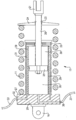
도 1은 인보드 푸시로드(inboard pushrod) 작동식 에너지 저장 매체와 모션 조절을 위한 종래의 더블 위시본 서스펜션(double wishbone suspension)을 이용하는 차량의 한 코너에 장착된 본 발명의 제1 실시예를 예시한다. 토션 바 스프링(10)이 통상적으로 푸시로드(100)와 로커(101) 장치에 의해 작동된다. 토션 바 스프링(10)은 로커(01)의 회전 중심으로부터 구동되며 푸시로드(100)는 서스펜션 스핀들(107)에 연결되어 맞은편 단부에서 로커(101)에 결부된다(attached). 휠(105), 타이어(106), 브레이크 조립체(108)와 스핀들(107)은 일련의 모션 컨트롤 링크(110, 111, 112 및 113)에 의해 차량 구조물에 결부되는 차량의 언스프렁 코너(unsprung corner)를 구성하며, 상기 일련의 모션 컨트롤 링크는 언스프렁 코너의 움직임(movement)을 사전결정된 기능적으로 바람직한 모션 경로(motion 경로)를 따라 하나의 자유도에만 국한시키도록 구성된다. 언스프렁 코너가 모션 경로를 통해 움직일 때, 언스프렁 코너는 푸시로드(100)에 의해 로커(101)를 회전시키고 토션 바 스프링(10)에 토크(torque)를 포함한다. 댐퍼(13), 가령, 통상적인 쇼크 업소버(shock absorber)가, 언스프렁 코너의 모션을 댐핑하기 위해 토션 바 스프링(10)의 종축(longitudinal axis)으로부터 일정 거리에서 차량 지지 구조물과 로커(101) 사이에 연결된다. 댐퍼(13)는 원할 시에는 상이한 형상으로 본 시스템에 일체형으로 구성될 수 있다(incorporated)는 것을 이해해야 한다. Figure 1 illustrates a first embodiment of the present invention mounted on one corner of a vehicle using an inboard pushrod-operated energy storage medium and a conventional double wishbone suspension for motion control. do. The
제1 작동 모드에서, 로커(101)의 회전 모션(rotary motion)은 직렬로 배열된 코일 스프링(11)과 토션 바 스프링(10)의 조합으로 변형 에너지(strain energy)를 저장하거나 릴리스하여, 코일 스프링(11)은 작동 암(12)에 의해 토션 바 스프링(10)의 원위 단부에서 회전 모션에 의해 이동된다(displaced). 코일 스프링(11)은 접지 조인트(16)에 의해 작동 암(12)의 맞은편 단부에서 차량 구조물에 고정된다(anchored). 상기 제1 작동 모드에서, 차량의 언스프렁 코너에 작용하는 조합된 탄성률(combined spring rate) Ksr은 다음 공식에 의해 정의된다: In the first operating mode the rotary motion of the
1/ Ksr = 1/Ktb + 1/Kcs (공식 2) 1 / Ksr = 1 / Ktb + 1 / Kcs (Formula 2)
여기서 Ktb는 토션 바 스프링(10)의 탄성률이며 Kcs는 코일 스프링(11)의 탄성률이다. 상기 공식은 조합된 탄성률(Ksr)이 개별 탄성률보다 낮으며 그에 따라 낮은 고유 진동수가 최적의 탑승 안락성 설정에 제공된다. Where K tb is the elastic modulus of the
제2 작동 모드에서, 코일 스프링(11)과 동축 구성된(coaxial) 유압 록아웃 액츄에이터(15)가 작동되어, 견고한 링크(solid link)로서 거동하며(behaved) 코일 스프링(11)이 수축되는 것을 방지한다. 이런 방식으로, 로커(101)의 회전 모션은, 원위 단부가 능동 록아웃(active lockout) 액츄에이터(15)에 의해 차량 구조물에 고정됨에 따라, 오직 토션 바 스프링(10)에서 변형 에너지를 저장하거나 릴리스한다. 상기 제2 작동 모드에서, 차량의 언스프렁 코너에 작용하는 탄성률 Ksr은 다음의 공식으로 정의된다: In the second operating mode the coaxial
Ksr = Ktb (공식 3) Ksr = Ktb (Formula 3)
상기 제2 작동 모드에서, 차량의 언스프렁 코너에 작용하는 탄성률은 제1 작동 모드를 넘어 실질적으로 증가되며, 그에 따라 고유 진동수도 증가되어 최적의 조종 설정을 제공한다. In the second operating mode, the modulus of elasticity acting on the unsealing corner of the vehicle is substantially increased beyond the first operating mode, whereby the natural frequency is also increased to provide the optimum steering setting.
유압 록아웃 액츄에이터(15)는 도 2에 상세하게 예시되는데, 몸체(22), 샤프트(20), 샤프트 클레비스(21), 접지 조인트(16), 상부 스프링 플레이트(24), 하부 스프링 퍼치(27) 및 유압 매니폴드 캡(26)으로 구성된다. 서클립(23)이 샤프트(20)와 상부 스프링 플레이트(24) 사이에 제공되는데, 이는 도 3에 가장 잘 예시된다. 접지 조인트(16)는 볼트(bolt) 또는 이와 비슷한 파스너(fastener)로 차량 구조물에 장착되며 샤프트 클레비스(21)는 작동 암(12)의 외부 지점에 회전 가능하게 결부된다(rotationally attached). 코일 스프링(11)은 록아웃 액츄에이터(15)의 몸체(22)와 샤프트(20) 주위에 동축 배열되며(coaxially located), 한 단부는 하부 스프링 퍼치(27)에 의해 지지되고 다른 단부는 상부 스프링 플레이트(24)에 의해 사전하중으로 고정된다(held in preload). 또한, 도 3에서는, 어떻게 유압 록아웃 액츄에이터(15)의 샤프트(20)가 원통형 보어(29) 내에서 이동하기에 적합한 원통형 피스톤(25)에 견고하게 결부되는지에 대해 잘 도시되어 있다. 이런 방식으로, 원통형 보어(29)는 적절한 유압 유체로 채워진 2개의 가변 작동 용적(30 및 35)으로 나뉜다. 상측 유압 용적(30)과 제1 외측 포트(32) 및 하측 유압 용적(35)과 제2 외측 포트(36) 사이에 유압 경로(31)를 제공하기 위하여, 유압 매니폴드 캡(26)이 내부에 배열된다. The
제1 작동 모드에서, 두 외측 포트(32 및 36)는 서로 직접적으로 연결되어 유압 유체는 두 유압 용적(30 및 35) 사이에서 자유로이 흐를 수 있게 된다. 이런 방식으로, 원통형 피스톤(25)은 원통형 보어(29) 내에서 자유로이 이동되며 코일 스프링(11)의 움직임은 방해받지 않아서(unimpeded) 토션 바 스프링(10)과 직렬로 작동될 수 있게 된다. In the first operating mode, the two
제2 작동 모드에서, 두 외측 포트(32 및 36)는 서로로부터 차단되며(blocked) 그에 따라 유압 유체가 두 유압 용적(30 및 35) 사이에서 흐르는 것이 방지된다. 이런 방식으로, 원통형 피스톤(25)은 원통형 보어(29) 내에서 이동될 수 없으며 코일 스프링(11)이 고정되고, 그에 따라 오직 토션 바 스프링(10)만이 서스펜션 움직임에 의해 제공된 에너지를 저장할 수 있게 된다. In the second mode of operation, the two
유압 록아웃 액츄에이터(15)의 두 외측 포트(32 및 36) 사이의 연결을 개폐하도록 사용되는 유압 조절 회로(hydraulic control circuit)의 개략도가 도 4에 예시된다. 2-포트, 2-위치, 전기적 파일럿형(electrically piloted) 유압 밸브(40)가, 각각, 유압 라인(33 및 37)에 의해 제1 외측 포터(32)와 제2 외측 포터(36) 사이에 연결된다. 유압 밸브(40)는 유압 라인(33 및 37)이 차단 없이 직접 연결되도록 정상적으로 개방될 수 있게끔 구성된다. 상기 형상에서, 유압 유체는 두 유압 용적(30 및 35) 사이에서 자유로이 흐를 수 있다. 이런 방식으로, 원통형 피스톤(25)은 원통형 보어(29) 내에서 자유롭게 이동된다. A schematic diagram of a hydraulic control circuit used to open and close the connection between the two
적절한 전기 신호가 유압 밸브(40)에 제공되면, 닫힘 또는 차단 위치로 전환되며, 유압 유체가 두 유압 라인(33 및 37) 사이에서 흐르는 것이 방지되고(prohibited) 그에 따라 각각 유압 용적(30 및 35)에서 흐르는 것이 방지된다. 상기 모드에서, 원통형 피스톤(25)은 원통형 보어(29) 내에서는 이동될 수 없다. 뿐만 아니라, 실제 작동을 위해, 유압 록아웃 액츄에이터(15)에 삽입되는 샤프트(20)에 의해 이동되는 유압 유체가 저장될 수 있도록 일정 용적을 제공하기 위하여, 컴펜세이터(compensator)(50)가 유압 라인(33) 내에서 유압 회로에 삽입된다. 컴펜세이터(50)는 유압 저장 용적(51), 플로팅 피스톤(53) 및 압축 가스 용적(52)으로 구성되며, 샤프트(20)가 유압 록아웃 액츄에이터(15)에 삽입되고, 유압 밸브(40)가 정상적으로 개방 위치에 있을 때, 샤프트(20)에 의해 이동되는 유압 유체는 유압 저장 용적(51) 내에 저장되도록 구성된다. 샤프트(20)가 유압 록아웃 액츄에이터(15)로부터 나오고(leave), 유압 밸브(40)가 정상적으로 개방 위치에 있을 때에는, 저장 용적(51) 내의 유압 유체는 압축 가스 용적(52)에 의해 유압 록아웃 액츄에이터(15) 내로 다시 들어가게 된다. 유압 밸브(40)가 전기 신호를 받아 닫히면, 피스톤(25)은 필요 시에 코일 스프링(11)이 물러나도록(defeat) 내부 방향을 향하는 모션(inward motion)으로부터 고정된다. When an appropriate electrical signal is provided to the
이런 방식으로, 코일 스프링(11)은 선택적으로 고정될 수 있으며(selectably locked out), 그에 따라, 차량의 코너에 작용하는 총 탄성률 Ksr은 차량 하중 또는 탑승 높이에 상관없이 2개의 개별 작동 모드 사이에서 능동적으로 전환된다(actively switched). 이에 따라, 상대적으로 높은 고유 진동수의 특징을 가진 최적의 조종 설정과 상대적으로 낮은 고유 진동수의 특징을 가진 최적의 탑승 안락성 설정 사이에서 선택하는 방법이 제공된다. 실제로 4륜 구동 차량(four wheel vehicle)에 적용되는 것을 보면, 위치 센서가 각각의 서스펜션 코너의 4개의 록아웃 액츄에이터(15) 각각에 제공될 수 있으며, 그에 따라 4개의 유압 밸브(40)가 상응하는 탑승 높이를 유지하기 위하여 조절되어 닫힘 또는 차단 위치로 전환될 수 있다. In this way, the
본 발명의 추가적인 실시예에서, 유압 압력 공급원, 가령, 펌프 또는 어큐뮬레이터(accumulator)가 삽입되어 유압 록아웃 액츄에이터(15)의 원통형 피스톤(25)이 전력을 공급받아 사전결정된 위치로 갈 수 있으며, 그에 따라 차량의 모든 네 코너는 차량의 탑승 및 조종 요건을 위해 일치되고 최적화된 탑승 높이가 될 수 있다. In a further embodiment of the invention, a hydraulic pressure source, such as a pump or accumulator, is inserted to allow the
다시, 도 1을 보면, 코일 스프링(11)과 토션 바 스프링(10)가 직렬로 작동할 때, 제1 작동 모드에서, 차량의 코너의 탑승 높이는 코너 질량(corner mass) 및 총 조합 급수 탄성률(overall combined series spring rate)에 의해 결정된다. 탑승 높이의 초기 설정(initial setting)은 일반적으로 스크루 스레드 슬리브(screw thread sleeve) 또는 이와 비슷한 장치에 의해 푸시로드(100)를 연장하거나 철회함으로써 조절된다. 유압 록아웃 액츄에이터(15)가 작동되고 코일 스프링(11)이 고정되면, 평균 탑승 높이는 자연스럽게 증가되며, 추가적인 간섭(intervention) 없이도, 코너 질량이 동일하게 유지되기 때문에, 총 탄성률도 실질적으로 증가된다. 증가된 고유 진동수 및 낮은 탑승 높이가 최적의 우수한 조합을 제공하기 때문에, 이렇게 증가된 탑승 높이는 최적의 조종 상황을 구현하도록 바라는 것과는 정반대인 것이다. 도 5는 최적의 조종 설정을 제공하기 위하여 코일 스프링(11)이 고정되고 고유 진동수가 증가될 때 이상적인 사전결정된 낮은 탑승 높이를 제공하는 유압 회로의 개략도이다. 2-포트, 2-위치, 전기적 파일럿형 유압 밸브(40)가, 각각, 유압 라인(33 및 37)에 의해 유압 록아웃 액츄에이터(15)의 제1 외측 포터(32)와 제2 외측 포터(36) 사이에 연결된다. 유압 밸브(40)는 유압 라인(33 및 37)이 차단 없이 직접 연결되도록 정상적으로 개방될 수 있게끔 구성된다. 상기 형상에서, 유압 유체는 두 유압 용적(30 및 35) 사이에서 자유로이 흐를 수 있다. 이런 방식으로, 원통형 피스톤(25)은 원통형 보어(29) 내에서 자유롭게 이동된다. 앞에서 기술된 것과 같이, 실제 작동을 위해, 유압 록아웃 액츄에이터(15)에 삽입되는 샤프트(20)에 의해 이동되는 유압 유체가 저장될 수 있도록 일정 용적을 제공하기 위하여, 컴펜세이터(50)가 유압 라인(37) 내에서 유압 회로에 삽입된다. 또한, 유압 펌프(62), 또는 이와 비슷한 압력 공급원이 제공되어, 리저버(reservoir)(63)로부터 저압의 유압 유체를 끌어내어(draw) 상기 유압 유체를 유압 라인(38)으로 전달된다. 제2의 2-포트, 2-위치, 전기적 파일럿형 유압 밸브(60)가 유압 라인(38 및 33) 사이에 연결된다. 유압 밸브(60)는 유압 펌프(62)에 의해 생성된 압력이 유압 라인(33)으로 유입되는 것을 차단하도록 일반적으로 닫히도록 구성된다. 제3의 2-포트, 2-위치, 전기적 파일럿형 유압 밸브(61)가 유압 라인(37)과 리저버(63) 사이에 연결된다. 유압 밸브(61)는 유압 라인(37)이 리저버로부터 차단되도록 일반적으로 닫히게끔 구성된다. 유압 용적(35 및 51)과 유압 라인(37)에 사전결정된 최소 압력을 유지하기 위하여, 셀프-파일럿형(self-piloted) 압력 릴리프 밸브(200)가 유압 밸브(61)와 리저버(63) 사이에 추가로 삽입된다. 유압 밸브(40, 60 및 61)에 적절한 전기 신호가 동시에 제공되면, 이 유압 밸브들은 모두 상태가 변경되며 유압 밸브(40)는 닫힘 또는 차단 위치로 전환되어, 유압 유체가 두 유압 라인(33 및 37) 사이에서 흐르는 것이 방지되고 그에 따라 각각 유압 용적(30 및 35)에서 흐르는 것이 방지된다. 또한, 유압 밸브(60)는 개방 위치로 전환되고 고압의 유압 유체가 유압 라인(33)에 의해 유압 용적(30) 내로 직접 흐를 수 있으며, 유압 밸브(61)도 개방 위치로 전환되고 유압 용적(35) 내의 유압 유체는 압력 릴리프 밸브(200)와 유압 라인(37)에 의해 리저버(63)로 흐를 수 있다. 압력 릴리프 밸브(200)는 유압 라인(37) 내에 일정 압력을 유지하여 유압 밸브(61)가 개방 위치로 전환될 때 컴펜세이터(50)가 유압 저장 용적(51)으로부터 배출되는 것을 방지하도록 구성된다. 이런 방식으로, 원통형 피스톤(25)은 차량의 서스펜션 하중에 의해 생성되는 압력보다 현저하게 더 높도록 결정된 압력에 의해 유압 록아웃 액츄에이터(15)의 원통형 보어(29) 내에서 완전히 철회된 위치로 이동된다. 조절식 스톱(adjustable stop)(39)이 추가로 제공되어, 코일 스프링(11)이 고정되었을 때 제2 작동 모드에서 유압 록아웃 액츄에이터(15)의 철회된 위치가 차량의 정확한 탑승 높이에 꼭 맞도록 구성될 수 있다. 1, when the
이런 방식으로, 코일 스프링(11)은 선택적으로 고정될 수 있으며, 그에 따라, 차량의 코너에 작용하는 총 탄성률 Ksr은 사전결정된 탑승 높이에 상관없이 2개의 개별 작동 모드 사이에서 능동적으로 전환된다. 이에 따라, 상대적으로 높은 고유 진동수와 낮은 탑승 높이의 특징을 가진 최적의 조종 설정과 상대적으로 낮은 고유 진동수와 높은 탑승 높이의 특징을 가진 최적의 탑승 안락성 설정 사이에서 선택하는 방법이 제공된다. 또한, 상기 기술된 유압적으로 전력을 공급받는 시스템은 차량의 균형을 해치지 않도록 하기 위해 4개의 모든 코너가 사전결정된 속도와 시간에서 정확한 탑승 높이에서 적절하게 구현된다. In this way, the
댐퍼(13)는 로커(101)에 의해 일반적으로 작동되도록 배열될 수 있다. 또한, 댐퍼는 종래 기술에 알려진 것과 같이 적응형(adaptive)으로 구성될 수 있으며, 그에 따라 차량의 코너에 작용하는 총 탄성률 Ksr은 두 모드 사이에서 능동적으로 전환되어 댐핑 특성(damping characteristics)이 선택된 고유 진동수에 적절하게 일치될 수 있다. The
본 발명의 예시된 실시예들에서는 특정 시스템이 기술되었지만, 그 밖의 다른 시스템들도 사용될 수 있다는 것을 이해해야 한다. 예를 들어, 위에서 기술된 차량의 서스펜션 시스템은, 코일 스프링(11) 대신 제2 토션 바가 사용되고 록아웃 액츄에이터가 두 토션 바 사이에 위치되도록 변경될 수도 있다. 록아웃 액츄에이터는 기술된 유압 장치 대신에 전기 기계장치일 수도 있다. 예시된 실시예에서는 서로 다른 예들이 특정 구성요소들을 가지지만, 본 발명의 실시예들은 이들 특정 조합에만 제한되는 것이 아니다. 본 발명에서는 특정 실시예가 기술되었지만, 통상의 기술자라면 본 발명의 범위를 벗어나지 않고도 특정 변형예들도 가능하다는 것을 이해할 것이다. 그런 이유로, 하기 청구항들이 본 발명의 진정한 범위 및 내용을 결정하는 것으로 간주되어야 한다. It should be understood that although certain systems have been described in the illustrated embodiments of the present invention, other systems may also be used. For example, the suspension system of the vehicle described above may be modified such that a second torsion bar is used instead of the
또한, 특정 구성요소들이 본 발명의 예시된 실시예에 기술되었지만, 그 밖의 다른 구성요소들도 사용될 수 있다는 것을 이해해야 한다. 특정 방법 단계들이 도시되고, 기술되고 청구되었지만, 이러한 단계들은, 그 외에 달리 언급되지 않는 한, 임의의 순서로 수행되거나, 개별적으로 또는 서로 조합되어 수행될 수 있다는 것을 이해해야 한다. In addition, while certain elements have been described in the illustrated embodiment of the invention, it should be understood that other elements may also be used. Although specific method steps are shown, described, and claimed, it should be understood that these steps may be performed in any order, performed individually, or in combination with each other, unless stated otherwise.
예시된 실시예에서는 서로 다른 예들이 특정 구성요소들을 가지지만, 본 발명의 실시예들은 이들 특정 조합에만 제한되는 것이 아니다. 본 발명의 실시예들 중 일부 구성요소 또는 특징들을 본 발명의 실시예들 중 또 다른 구성요소 또는 특징들과 조합하여 사용할 수도 있다. Although different examples have specific components in the illustrated embodiment, embodiments of the invention are not limited to these specific combinations. Some of the elements or features of the embodiments of the present invention may be used in combination with other elements or features of the embodiments of the present invention.
본 발명에서는 특정 실시예가 기술되었지만, 통상의 기술자라면 본 발명의 범위를 벗어나지 않고도 특정 변형예들도 가능하다는 것을 이해할 것이다. 그런 이유로, 하기 청구항들이 본 발명의 진정한 범위 및 내용을 결정하는 것으로 간주되어야 한다. Although specific embodiments have been described herein, it will be appreciated by those of ordinary skill in the art that various changes may be made without departing from the scope of the invention. For that reason, the following claims should be construed as determining the true scope and content of the present invention.
Claims (4)
차량의 한 코너의 언스프렁 매스와 스프렁 매스 사이에 배열된 푸시로드 작동식 인보드 스프링을 포함하되, 상기 푸시로드 작동식 인보드 스프링은 제1 사전결정된 탄성률 K1의 토션 바 스프링과 제2 사전결정된 탄성률 K2의 코일 스프링을 포함하고, 이들은 직렬로 배열되어 총 조합 탄성률 KT을 제공하며;
코일 스프링과 병렬로 배열된 록아웃 액츄에이터를 포함하되, 상기 록아웃 액츄에이터는, 제1 모드에서 코일 스프링이 자유로이 이동될 수 있고 제2 모드에서는 코일 스프링의 움직임을 방지하도록 구성되며,
록아웃 액츄에이터가 제1의 언로킹 모드에 있을 때에는 차량의 총 서스펜션 탄성률은 급수 공식 1/KT = 1/ K1 + 1/K2에 의해 정의되며, 록아웃 액츄에이터가 제2의 로킹 모드에 있을 때에는 차량의 총 서스펜션 탄성률은 KT = K1에 의해 정의된 것과 같이 실질적으로 더 높아서, 낮은 탄성률의 최적의 탑승 안락성 설정과 높은 탄성률의 최적의 조종 설정을 선택적으로 제공하는 것을 특징으로 하는, 선택적으로 전환가능한 이중 탄성률 차량 서스펜션 시스템. A selectively switchable dual modulus vehicle suspension system comprising:
A pushrod actuated inboard spring arranged between an unsprung mass and a sprung mass at one corner of the vehicle, the pushrod actuated inboard spring comprising a torsion bar spring of a first predetermined modulus of elasticity K 1 , 2 coil springs of a predetermined modulus of elasticity K 2 , which are arranged in series to provide a total combined modulus K T ;
Out actuator arranged in parallel with the coil spring, wherein the lock-out actuator is configured to freely move the coil spring in the first mode and to prevent movement of the coil spring in the second mode,
When the lockout actuator is in the first unlocking mode, the vehicle's total suspension modulus is defined by the feed formula 1 / K T = 1 / K 1 + 1 / K 2 , and the lockout actuator is in the second locking mode , The total suspension elastic modulus of the vehicle is substantially higher, as defined by K T = K 1 , to selectively provide optimal ride comfort settings of low elastic modulus and high modulus of elasticity. A selectively switchable dual modulus vehicle suspension system.
Applications Claiming Priority (3)
| Application Number | Priority Date | Filing Date | Title |
|---|---|---|---|
| US201662276499P | 2016-01-08 | 2016-01-08 | |
| US62/276,499 | 2016-01-08 | ||
| PCT/US2017/012588 WO2017120509A1 (en) | 2016-01-08 | 2017-01-06 | Dual rate vehicle suspension system |
Publications (2)
| Publication Number | Publication Date |
|---|---|
| KR20180098602A true KR20180098602A (en) | 2018-09-04 |
| KR102088121B1 KR102088121B1 (en) | 2020-03-12 |
Family
ID=57868410
Family Applications (1)
| Application Number | Title | Priority Date | Filing Date |
|---|---|---|---|
| KR1020187021292A Active KR102088121B1 (en) | 2016-01-08 | 2017-01-06 | Dual modulus vehicle suspension system |
Country Status (12)
| Country | Link |
|---|---|
| US (1) | US10807434B2 (en) |
| EP (1) | EP3400142B1 (en) |
| JP (2) | JP2019501067A (en) |
| KR (1) | KR102088121B1 (en) |
| CN (1) | CN108473017B (en) |
| AU (1) | AU2017206062A1 (en) |
| BR (1) | BR112018013721B1 (en) |
| CA (1) | CA3009807C (en) |
| ES (1) | ES2817757T3 (en) |
| MX (1) | MX2018008370A (en) |
| RU (1) | RU2705472C1 (en) |
| WO (1) | WO2017120509A1 (en) |
Families Citing this family (10)
| Publication number | Priority date | Publication date | Assignee | Title |
|---|---|---|---|---|
| US10639954B2 (en) * | 2016-09-23 | 2020-05-05 | Jay O'Connell | Multi-link suspension system |
| IT201800005419A1 (en) * | 2018-05-16 | 2019-11-16 | AUTOMOTIVE SUSPENSION FOR SPORTS CAR | |
| DE102018131850A1 (en) * | 2018-12-12 | 2020-06-18 | Schaeffler Technologies AG & Co. KG | Wheel module for a motor vehicle and corresponding motor vehicle |
| US11639081B2 (en) | 2020-07-29 | 2023-05-02 | Ferrari S.P.A. | Device and apparatus for the height adjustment of a road vehicle and relative road vehicle |
| US11648812B2 (en) | 2020-08-21 | 2023-05-16 | Toyota Motor Engineering & Manufacturing North America, Inc. | No roll torsion bar |
| US11192414B1 (en) | 2020-10-13 | 2021-12-07 | Xtravel Suspension, Llc | Suspension system |
| US11571939B2 (en) | 2020-10-13 | 2023-02-07 | Xtravel Suspension, Llc | Suspension system |
| US20220250430A1 (en) * | 2021-02-11 | 2022-08-11 | GM Global Technology Operations LLC | Multilink mid-height suspension assembly for motor vehicles |
| WO2022253403A1 (en) * | 2021-05-31 | 2022-12-08 | Volvo Truck Corporation | A bump stop arrangement |
| US11511581B1 (en) | 2021-06-16 | 2022-11-29 | Xtravel Suspension, Llc | Suspension system |
Citations (3)
| Publication number | Priority date | Publication date | Assignee | Title |
|---|---|---|---|---|
| JPS59180030U (en) * | 1983-05-19 | 1984-12-01 | 三菱製鋼株式会社 | Variable spring constant spring suspension |
| JPH1122775A (en) * | 1997-07-07 | 1999-01-26 | Isuzu Motors Ltd | Spring constant variable spring device and vehicle suspension device |
| US20060197301A1 (en) * | 2005-03-02 | 2006-09-07 | Dr. Ing. H.C.F. Porsche Ag | Wheel suspension |
Family Cites Families (28)
| Publication number | Priority date | Publication date | Assignee | Title |
|---|---|---|---|---|
| DE1022478B (en) * | 1955-06-16 | 1958-01-09 | Daimler Benz Ag | Device for adjusting the suspension for motor vehicles, in particular for counterbalancing the fuel consumed by sports and racing cars |
| US3083034A (en) | 1960-11-10 | 1963-03-26 | Ford Motor Co | Wheel suspension with ride control |
| US3773346A (en) | 1972-01-03 | 1973-11-20 | Moog Industries Inc | Vehicle suspension system |
| JPS5060716U (en) * | 1973-10-02 | 1975-06-04 | ||
| US4145073A (en) * | 1977-04-07 | 1979-03-20 | Caterpillar Tractor Co. | Lockup system for a vehicle suspension mechanism |
| DE3737760A1 (en) | 1987-11-06 | 1989-05-18 | Pfister Gmbh | METHOD FOR OPTIMIZING THE DRIVING PROPERTY OF VEHICLES |
| JPH03273919A (en) * | 1990-03-23 | 1991-12-05 | Nissan Shatai Co Ltd | Vehicle floor height adjusting device |
| JPH0450019A (en) * | 1990-06-19 | 1992-02-19 | Mazda Motor Corp | Vehicle suspension device |
| DE4110651A1 (en) * | 1991-04-02 | 1992-10-08 | Ingelheim Peter Graf Von | Regulated vehicle spring system - has adjustment or switching facility to enable system rating to be altered |
| CA2117945C (en) | 1994-10-12 | 2003-03-25 | Laurence J. Holt | Suspension system |
| JPH08332822A (en) * | 1995-06-08 | 1996-12-17 | Isuzu Motors Ltd | Vehicle height adjustment mechanism |
| DE19521861C1 (en) | 1995-06-16 | 1996-10-24 | Porsche Ag | Device for influencing coil spring characteristics of vehicle's wheel suspension |
| JPH09207537A (en) * | 1996-01-31 | 1997-08-12 | Kayaba Ind Co Ltd | Spring constant switching structure |
| US5725239A (en) | 1996-03-26 | 1998-03-10 | Monroe Auto Equipment | Adaptive load dependent suspension system |
| US5687960A (en) * | 1996-04-12 | 1997-11-18 | Hyundai Motor Company | Torsion bar assembly for vehicle suspension system |
| US6357771B1 (en) | 2000-05-25 | 2002-03-19 | Meritor Light Vehicle Systems, Inc. | Torsion bar with variable rate anchor arm for a vehicle suspension system |
| US6945522B2 (en) * | 2002-04-30 | 2005-09-20 | Meritor Heavy Vehicle Technology, Llc | Multi-rate torsion bar independent suspension spring |
| US6923434B2 (en) | 2003-11-10 | 2005-08-02 | The Goodyear Tire & Rubber Company | Dual height airspring having adjusted spring rate |
| JP4127298B2 (en) * | 2006-06-14 | 2008-07-30 | トヨタ自動車株式会社 | Wheel body distance adjustment device and wheel body distance adjustment system |
| DE102007007630A1 (en) * | 2007-02-16 | 2008-08-21 | Bayerische Motoren Werke Aktiengesellschaft | Vehicle, especially motorcycle, with a strut with adjustable spring rate |
| CN100544981C (en) * | 2007-12-11 | 2009-09-30 | 中国三江航天工业集团公司 | Torsion bar coil spring composite suspension device |
| US20100225084A1 (en) * | 2008-12-30 | 2010-09-09 | Darco Trust | Vehicle suspension system |
| US8356807B2 (en) * | 2010-06-24 | 2013-01-22 | Miner Elastomer Products Corporation | Dual rate shock absorbing apparatus for a suspension system of a heavy off-road vehicle |
| DE102010033002A1 (en) | 2010-07-31 | 2012-02-02 | Audi Ag | Achssteller a motor vehicle |
| DE102012202988A1 (en) * | 2012-02-28 | 2013-08-29 | Zf Friedrichshafen Ag | Connecting arrangement for a vehicle wheel suspension |
| JP5936125B2 (en) * | 2012-11-20 | 2016-06-15 | Kyb株式会社 | Vehicle height adjustment device and method of assembling vehicle height adjustment device |
| DE102013002713B4 (en) * | 2013-02-16 | 2014-08-28 | Audi Ag | A torsion bar spring arrangement for a wheel suspension of a motor vehicle |
| US9150070B2 (en) * | 2013-10-18 | 2015-10-06 | GM Global Technology Operations LLC | Actively controlled torsion bar suspension |
-
2017
- 2017-01-06 CA CA3009807A patent/CA3009807C/en active Active
- 2017-01-06 KR KR1020187021292A patent/KR102088121B1/en active Active
- 2017-01-06 EP EP17701236.6A patent/EP3400142B1/en active Active
- 2017-01-06 JP JP2018535097A patent/JP2019501067A/en active Pending
- 2017-01-06 AU AU2017206062A patent/AU2017206062A1/en not_active Abandoned
- 2017-01-06 CN CN201780005901.1A patent/CN108473017B/en active Active
- 2017-01-06 RU RU2018128745A patent/RU2705472C1/en not_active IP Right Cessation
- 2017-01-06 WO PCT/US2017/012588 patent/WO2017120509A1/en not_active Ceased
- 2017-01-06 MX MX2018008370A patent/MX2018008370A/en unknown
- 2017-01-06 ES ES17701236T patent/ES2817757T3/en active Active
- 2017-01-06 US US16/066,161 patent/US10807434B2/en active Active
- 2017-01-06 BR BR112018013721-9A patent/BR112018013721B1/en active IP Right Grant
-
2020
- 2020-05-22 JP JP2020089884A patent/JP7012121B2/en active Active
Patent Citations (3)
| Publication number | Priority date | Publication date | Assignee | Title |
|---|---|---|---|---|
| JPS59180030U (en) * | 1983-05-19 | 1984-12-01 | 三菱製鋼株式会社 | Variable spring constant spring suspension |
| JPH1122775A (en) * | 1997-07-07 | 1999-01-26 | Isuzu Motors Ltd | Spring constant variable spring device and vehicle suspension device |
| US20060197301A1 (en) * | 2005-03-02 | 2006-09-07 | Dr. Ing. H.C.F. Porsche Ag | Wheel suspension |
Also Published As
| Publication number | Publication date |
|---|---|
| EP3400142B1 (en) | 2020-06-17 |
| JP7012121B2 (en) | 2022-01-27 |
| BR112018013721B1 (en) | 2023-09-26 |
| ES2817757T3 (en) | 2021-04-08 |
| WO2017120509A1 (en) | 2017-07-13 |
| CA3009807C (en) | 2019-09-17 |
| JP2020142797A (en) | 2020-09-10 |
| CN108473017B (en) | 2021-02-26 |
| EP3400142A1 (en) | 2018-11-14 |
| MX2018008370A (en) | 2019-07-04 |
| JP2019501067A (en) | 2019-01-17 |
| CN108473017A (en) | 2018-08-31 |
| AU2017206062A1 (en) | 2018-07-12 |
| US10807434B2 (en) | 2020-10-20 |
| KR102088121B1 (en) | 2020-03-12 |
| RU2705472C1 (en) | 2019-11-07 |
| BR112018013721A2 (en) | 2018-12-11 |
| US20190009632A1 (en) | 2019-01-10 |
| CA3009807A1 (en) | 2017-07-13 |
Similar Documents
| Publication | Publication Date | Title |
|---|---|---|
| KR102088121B1 (en) | Dual modulus vehicle suspension system | |
| EP2058155B1 (en) | Suspension device and method during spring action and/or damping action for a vehicle | |
| RU2408475C2 (en) | Hydraulic suspension for transport facility | |
| JP3951728B2 (en) | Stabilizer device | |
| EP3290244A1 (en) | Combined spring compensation suspension device | |
| JP7835513B2 (en) | Dual-rate vehicle suspension system with adjustable ride height | |
| JP2005503957A (en) | Vehicle suspension system | |
| CN101238003A (en) | Hydraulic systems for vehicle suspension systems | |
| US20210260949A1 (en) | Hydraulic suspension system for off-road vehicles | |
| US20080203694A1 (en) | Vehicle | |
| US11897307B1 (en) | Trailer suspension | |
| WO2018092110A1 (en) | Vehicle wheel suspension provided with active adjustment system for adjusting in a controlled manner the overall stiffness of the suspension | |
| US11565565B2 (en) | Vehicle overload suspension system | |
| DE102011076973A1 (en) | Method for controlling the damping force on an axle of a chassis for a motor vehicle | |
| AU2020396288B2 (en) | Vehicle component for a utility vehicle, in particular an off-road utility vehicle | |
| Harish et al. | Design and Analysis of Active Suspension System | |
| KR20050037743A (en) | Control system of stabilizer bar | |
| KR20100056705A (en) | Shock absorber for suspension system | |
| KR19980059817A (en) | Vehicle suspension |
Legal Events
| Date | Code | Title | Description |
|---|---|---|---|
| A201 | Request for examination | ||
| P11-X000 | Amendment of application requested |
St.27 status event code: A-2-2-P10-P11-nap-X000 |
|
| P13-X000 | Application amended |
St.27 status event code: A-2-2-P10-P13-nap-X000 |
|
| PA0105 | International application |
St.27 status event code: A-0-1-A10-A15-nap-PA0105 |
|
| PA0201 | Request for examination |
St.27 status event code: A-1-2-D10-D11-exm-PA0201 |
|
| PG1501 | Laying open of application |
St.27 status event code: A-1-1-Q10-Q12-nap-PG1501 |
|
| D13-X000 | Search requested |
St.27 status event code: A-1-2-D10-D13-srh-X000 |
|
| D14-X000 | Search report completed |
St.27 status event code: A-1-2-D10-D14-srh-X000 |
|
| E902 | Notification of reason for refusal | ||
| PE0902 | Notice of grounds for rejection |
St.27 status event code: A-1-2-D10-D21-exm-PE0902 |
|
| R17-X000 | Change to representative recorded |
St.27 status event code: A-3-3-R10-R17-oth-X000 |
|
| E701 | Decision to grant or registration of patent right | ||
| PE0701 | Decision of registration |
St.27 status event code: A-1-2-D10-D22-exm-PE0701 |
|
| GRNT | Written decision to grant | ||
| PR0701 | Registration of establishment |
St.27 status event code: A-2-4-F10-F11-exm-PR0701 |
|
| PR1002 | Payment of registration fee |
St.27 status event code: A-2-2-U10-U12-oth-PR1002 Fee payment year number: 1 |
|
| PG1601 | Publication of registration |
St.27 status event code: A-4-4-Q10-Q13-nap-PG1601 |
|
| PR1001 | Payment of annual fee |
St.27 status event code: A-4-4-U10-U11-oth-PR1001 Fee payment year number: 4 |
|
| PR1001 | Payment of annual fee |
St.27 status event code: A-4-4-U10-U11-oth-PR1001 Fee payment year number: 5 |
|
| PR1001 | Payment of annual fee |
St.27 status event code: A-4-4-U10-U11-oth-PR1001 Fee payment year number: 6 |
|
| PR1001 | Payment of annual fee |
St.27 status event code: A-4-4-U10-U11-oth-PR1001 Fee payment year number: 7 |
|
| U11 | Full renewal or maintenance fee paid |
Free format text: ST27 STATUS EVENT CODE: A-4-4-U10-U11-OTH-PR1001 (AS PROVIDED BY THE NATIONAL OFFICE) Year of fee payment: 7 |