KR20180098600A - Gasoline particulate filter - Google Patents
Gasoline particulate filter Download PDFInfo
- Publication number
- KR20180098600A KR20180098600A KR1020187021204A KR20187021204A KR20180098600A KR 20180098600 A KR20180098600 A KR 20180098600A KR 1020187021204 A KR1020187021204 A KR 1020187021204A KR 20187021204 A KR20187021204 A KR 20187021204A KR 20180098600 A KR20180098600 A KR 20180098600A
- Authority
- KR
- South Korea
- Prior art keywords
- wall
- channels
- monolith
- catalyst
- osc
- Prior art date
- Legal status (The legal status is an assumption and is not a legal conclusion. Google has not performed a legal analysis and makes no representation as to the accuracy of the status listed.)
- Granted
Links
Images

Classifications
-
- B—PERFORMING OPERATIONS; TRANSPORTING
- B01—PHYSICAL OR CHEMICAL PROCESSES OR APPARATUS IN GENERAL
- B01J—CHEMICAL OR PHYSICAL PROCESSES, e.g. CATALYSIS OR COLLOID CHEMISTRY; THEIR RELEVANT APPARATUS
- B01J23/00—Catalysts comprising metals or metal oxides or hydroxides, not provided for in group B01J21/00
- B01J23/38—Catalysts comprising metals or metal oxides or hydroxides, not provided for in group B01J21/00 of noble metals
- B01J23/40—Catalysts comprising metals or metal oxides or hydroxides, not provided for in group B01J21/00 of noble metals of the platinum group metals
- B01J23/46—Ruthenium, rhodium, osmium or iridium
- B01J23/464—Rhodium
-
- B—PERFORMING OPERATIONS; TRANSPORTING
- B01—PHYSICAL OR CHEMICAL PROCESSES OR APPARATUS IN GENERAL
- B01D—SEPARATION
- B01D53/00—Separation of gases or vapours; Recovering vapours of volatile solvents from gases; Chemical or biological purification of waste gases, e.g. engine exhaust gases, smoke, fumes, flue gases, aerosols
- B01D53/34—Chemical or biological purification of waste gases
- B01D53/92—Chemical or biological purification of waste gases of engine exhaust gases
- B01D53/94—Chemical or biological purification of waste gases of engine exhaust gases by catalytic processes
- B01D53/9459—Removing one or more of nitrogen oxides, carbon monoxide, or hydrocarbons by multiple successive catalytic functions; systems with more than one different function, e.g. zone coated catalysts
-
- B—PERFORMING OPERATIONS; TRANSPORTING
- B01—PHYSICAL OR CHEMICAL PROCESSES OR APPARATUS IN GENERAL
- B01D—SEPARATION
- B01D53/00—Separation of gases or vapours; Recovering vapours of volatile solvents from gases; Chemical or biological purification of waste gases, e.g. engine exhaust gases, smoke, fumes, flue gases, aerosols
- B01D53/34—Chemical or biological purification of waste gases
- B01D53/92—Chemical or biological purification of waste gases of engine exhaust gases
- B01D53/94—Chemical or biological purification of waste gases of engine exhaust gases by catalytic processes
- B01D53/9445—Simultaneously removing carbon monoxide, hydrocarbons or nitrogen oxides making use of three-way catalysts [TWC] or four-way-catalysts [FWC]
- B01D53/945—Simultaneously removing carbon monoxide, hydrocarbons or nitrogen oxides making use of three-way catalysts [TWC] or four-way-catalysts [FWC] characterised by a specific catalyst
-
- B—PERFORMING OPERATIONS; TRANSPORTING
- B01—PHYSICAL OR CHEMICAL PROCESSES OR APPARATUS IN GENERAL
- B01D—SEPARATION
- B01D53/00—Separation of gases or vapours; Recovering vapours of volatile solvents from gases; Chemical or biological purification of waste gases, e.g. engine exhaust gases, smoke, fumes, flue gases, aerosols
- B01D53/34—Chemical or biological purification of waste gases
- B01D53/92—Chemical or biological purification of waste gases of engine exhaust gases
- B01D53/94—Chemical or biological purification of waste gases of engine exhaust gases by catalytic processes
-
- B—PERFORMING OPERATIONS; TRANSPORTING
- B01—PHYSICAL OR CHEMICAL PROCESSES OR APPARATUS IN GENERAL
- B01J—CHEMICAL OR PHYSICAL PROCESSES, e.g. CATALYSIS OR COLLOID CHEMISTRY; THEIR RELEVANT APPARATUS
- B01J21/00—Catalysts comprising the elements, oxides, or hydroxides of magnesium, boron, aluminium, carbon, silicon, titanium, zirconium, or hafnium
- B01J21/02—Boron or aluminium; Oxides or hydroxides thereof
- B01J21/04—Alumina
-
- B—PERFORMING OPERATIONS; TRANSPORTING
- B01—PHYSICAL OR CHEMICAL PROCESSES OR APPARATUS IN GENERAL
- B01J—CHEMICAL OR PHYSICAL PROCESSES, e.g. CATALYSIS OR COLLOID CHEMISTRY; THEIR RELEVANT APPARATUS
- B01J23/00—Catalysts comprising metals or metal oxides or hydroxides, not provided for in group B01J21/00
- B01J23/02—Catalysts comprising metals or metal oxides or hydroxides, not provided for in group B01J21/00 of the alkali- or alkaline earth metals or beryllium
- B01J23/04—Alkali metals
-
- B—PERFORMING OPERATIONS; TRANSPORTING
- B01—PHYSICAL OR CHEMICAL PROCESSES OR APPARATUS IN GENERAL
- B01J—CHEMICAL OR PHYSICAL PROCESSES, e.g. CATALYSIS OR COLLOID CHEMISTRY; THEIR RELEVANT APPARATUS
- B01J23/00—Catalysts comprising metals or metal oxides or hydroxides, not provided for in group B01J21/00
- B01J23/10—Catalysts comprising metals or metal oxides or hydroxides, not provided for in group B01J21/00 of rare earths
-
- B—PERFORMING OPERATIONS; TRANSPORTING
- B01—PHYSICAL OR CHEMICAL PROCESSES OR APPARATUS IN GENERAL
- B01J—CHEMICAL OR PHYSICAL PROCESSES, e.g. CATALYSIS OR COLLOID CHEMISTRY; THEIR RELEVANT APPARATUS
- B01J23/00—Catalysts comprising metals or metal oxides or hydroxides, not provided for in group B01J21/00
- B01J23/38—Catalysts comprising metals or metal oxides or hydroxides, not provided for in group B01J21/00 of noble metals
- B01J23/40—Catalysts comprising metals or metal oxides or hydroxides, not provided for in group B01J21/00 of noble metals of the platinum group metals
-
- B—PERFORMING OPERATIONS; TRANSPORTING
- B01—PHYSICAL OR CHEMICAL PROCESSES OR APPARATUS IN GENERAL
- B01J—CHEMICAL OR PHYSICAL PROCESSES, e.g. CATALYSIS OR COLLOID CHEMISTRY; THEIR RELEVANT APPARATUS
- B01J23/00—Catalysts comprising metals or metal oxides or hydroxides, not provided for in group B01J21/00
- B01J23/38—Catalysts comprising metals or metal oxides or hydroxides, not provided for in group B01J21/00 of noble metals
- B01J23/54—Catalysts comprising metals or metal oxides or hydroxides, not provided for in group B01J21/00 of noble metals combined with metals, oxides or hydroxides provided for in groups B01J23/02 - B01J23/36
- B01J23/56—Platinum group metals
- B01J23/63—Platinum group metals with rare earths or actinides
-
- B01J35/0006—
-
- B—PERFORMING OPERATIONS; TRANSPORTING
- B01—PHYSICAL OR CHEMICAL PROCESSES OR APPARATUS IN GENERAL
- B01J—CHEMICAL OR PHYSICAL PROCESSES, e.g. CATALYSIS OR COLLOID CHEMISTRY; THEIR RELEVANT APPARATUS
- B01J35/00—Catalysts, in general, characterised by their form or physical properties
- B01J35/19—Catalysts containing parts with different compositions
-
- B—PERFORMING OPERATIONS; TRANSPORTING
- B01—PHYSICAL OR CHEMICAL PROCESSES OR APPARATUS IN GENERAL
- B01J—CHEMICAL OR PHYSICAL PROCESSES, e.g. CATALYSIS OR COLLOID CHEMISTRY; THEIR RELEVANT APPARATUS
- B01J35/00—Catalysts, in general, characterised by their form or physical properties
- B01J35/50—Catalysts, in general, characterised by their form or physical properties characterised by their shape or configuration
- B01J35/56—Foraminous structures having flow-through passages or channels, e.g. grids or three-dimensional [3D] monoliths
-
- B—PERFORMING OPERATIONS; TRANSPORTING
- B01—PHYSICAL OR CHEMICAL PROCESSES OR APPARATUS IN GENERAL
- B01J—CHEMICAL OR PHYSICAL PROCESSES, e.g. CATALYSIS OR COLLOID CHEMISTRY; THEIR RELEVANT APPARATUS
- B01J37/00—Processes, in general, for preparing catalysts; Processes, in general, for activation of catalysts
- B01J37/02—Impregnation, coating or precipitation
- B01J37/0215—Coating
- B01J37/0228—Coating in several steps
-
- B—PERFORMING OPERATIONS; TRANSPORTING
- B01—PHYSICAL OR CHEMICAL PROCESSES OR APPARATUS IN GENERAL
- B01J—CHEMICAL OR PHYSICAL PROCESSES, e.g. CATALYSIS OR COLLOID CHEMISTRY; THEIR RELEVANT APPARATUS
- B01J37/00—Processes, in general, for preparing catalysts; Processes, in general, for activation of catalysts
- B01J37/08—Heat treatment
-
- F—MECHANICAL ENGINEERING; LIGHTING; HEATING; WEAPONS; BLASTING
- F01—MACHINES OR ENGINES IN GENERAL; ENGINE PLANTS IN GENERAL; STEAM ENGINES
- F01N—GAS-FLOW SILENCERS OR EXHAUST APPARATUS FOR MACHINES OR ENGINES IN GENERAL; GAS-FLOW SILENCERS OR EXHAUST APPARATUS FOR INTERNAL-COMBUSTION ENGINES
- F01N13/00—Exhaust or silencing apparatus characterised by constructional features
-
- F—MECHANICAL ENGINEERING; LIGHTING; HEATING; WEAPONS; BLASTING
- F01—MACHINES OR ENGINES IN GENERAL; ENGINE PLANTS IN GENERAL; STEAM ENGINES
- F01N—GAS-FLOW SILENCERS OR EXHAUST APPARATUS FOR MACHINES OR ENGINES IN GENERAL; GAS-FLOW SILENCERS OR EXHAUST APPARATUS FOR INTERNAL-COMBUSTION ENGINES
- F01N3/00—Exhaust or silencing apparatus having means for purifying, rendering innocuous, or otherwise treating exhaust
- F01N3/02—Exhaust or silencing apparatus having means for purifying, rendering innocuous, or otherwise treating exhaust for cooling, or for removing solid constituents of, exhaust
- F01N3/021—Exhaust or silencing apparatus having means for purifying, rendering innocuous, or otherwise treating exhaust for cooling, or for removing solid constituents of, exhaust by means of filters
- F01N3/033—Exhaust or silencing apparatus having means for purifying, rendering innocuous, or otherwise treating exhaust for cooling, or for removing solid constituents of, exhaust by means of filters in combination with other devices
- F01N3/035—Exhaust or silencing apparatus having means for purifying, rendering innocuous, or otherwise treating exhaust for cooling, or for removing solid constituents of, exhaust by means of filters in combination with other devices with catalytic reactors
-
- F—MECHANICAL ENGINEERING; LIGHTING; HEATING; WEAPONS; BLASTING
- F01—MACHINES OR ENGINES IN GENERAL; ENGINE PLANTS IN GENERAL; STEAM ENGINES
- F01N—GAS-FLOW SILENCERS OR EXHAUST APPARATUS FOR MACHINES OR ENGINES IN GENERAL; GAS-FLOW SILENCERS OR EXHAUST APPARATUS FOR INTERNAL-COMBUSTION ENGINES
- F01N3/00—Exhaust or silencing apparatus having means for purifying, rendering innocuous, or otherwise treating exhaust
- F01N3/08—Exhaust or silencing apparatus having means for purifying, rendering innocuous, or otherwise treating exhaust for rendering innocuous
- F01N3/10—Exhaust or silencing apparatus having means for purifying, rendering innocuous, or otherwise treating exhaust for rendering innocuous by thermal or catalytic conversion of noxious components of exhaust
- F01N3/101—Three-way catalysts
-
- F—MECHANICAL ENGINEERING; LIGHTING; HEATING; WEAPONS; BLASTING
- F01—MACHINES OR ENGINES IN GENERAL; ENGINE PLANTS IN GENERAL; STEAM ENGINES
- F01N—GAS-FLOW SILENCERS OR EXHAUST APPARATUS FOR MACHINES OR ENGINES IN GENERAL; GAS-FLOW SILENCERS OR EXHAUST APPARATUS FOR INTERNAL-COMBUSTION ENGINES
- F01N3/00—Exhaust or silencing apparatus having means for purifying, rendering innocuous, or otherwise treating exhaust
- F01N3/08—Exhaust or silencing apparatus having means for purifying, rendering innocuous, or otherwise treating exhaust for rendering innocuous
- F01N3/10—Exhaust or silencing apparatus having means for purifying, rendering innocuous, or otherwise treating exhaust for rendering innocuous by thermal or catalytic conversion of noxious components of exhaust
- F01N3/18—Exhaust or silencing apparatus having means for purifying, rendering innocuous, or otherwise treating exhaust for rendering innocuous by thermal or catalytic conversion of noxious components of exhaust characterised by methods of operation; Control
- F01N3/20—Exhaust or silencing apparatus having means for purifying, rendering innocuous, or otherwise treating exhaust for rendering innocuous by thermal or catalytic conversion of noxious components of exhaust characterised by methods of operation; Control specially adapted for catalytic conversion
-
- F—MECHANICAL ENGINEERING; LIGHTING; HEATING; WEAPONS; BLASTING
- F01—MACHINES OR ENGINES IN GENERAL; ENGINE PLANTS IN GENERAL; STEAM ENGINES
- F01N—GAS-FLOW SILENCERS OR EXHAUST APPARATUS FOR MACHINES OR ENGINES IN GENERAL; GAS-FLOW SILENCERS OR EXHAUST APPARATUS FOR INTERNAL-COMBUSTION ENGINES
- F01N3/00—Exhaust or silencing apparatus having means for purifying, rendering innocuous, or otherwise treating exhaust
- F01N3/08—Exhaust or silencing apparatus having means for purifying, rendering innocuous, or otherwise treating exhaust for rendering innocuous
- F01N3/10—Exhaust or silencing apparatus having means for purifying, rendering innocuous, or otherwise treating exhaust for rendering innocuous by thermal or catalytic conversion of noxious components of exhaust
- F01N3/24—Exhaust or silencing apparatus having means for purifying, rendering innocuous, or otherwise treating exhaust for rendering innocuous by thermal or catalytic conversion of noxious components of exhaust characterised by constructional aspects of converting apparatus
- F01N3/28—Construction of catalytic reactors
- F01N3/2803—Construction of catalytic reactors characterised by structure, by material or by manufacturing of catalyst support
-
- B—PERFORMING OPERATIONS; TRANSPORTING
- B01—PHYSICAL OR CHEMICAL PROCESSES OR APPARATUS IN GENERAL
- B01D—SEPARATION
- B01D2255/00—Catalysts
- B01D2255/10—Noble metals or compounds thereof
- B01D2255/102—Platinum group metals
- B01D2255/1021—Platinum
-
- B—PERFORMING OPERATIONS; TRANSPORTING
- B01—PHYSICAL OR CHEMICAL PROCESSES OR APPARATUS IN GENERAL
- B01D—SEPARATION
- B01D2255/00—Catalysts
- B01D2255/10—Noble metals or compounds thereof
- B01D2255/102—Platinum group metals
- B01D2255/1023—Palladium
-
- B—PERFORMING OPERATIONS; TRANSPORTING
- B01—PHYSICAL OR CHEMICAL PROCESSES OR APPARATUS IN GENERAL
- B01D—SEPARATION
- B01D2255/00—Catalysts
- B01D2255/10—Noble metals or compounds thereof
- B01D2255/102—Platinum group metals
- B01D2255/1025—Rhodium
-
- B—PERFORMING OPERATIONS; TRANSPORTING
- B01—PHYSICAL OR CHEMICAL PROCESSES OR APPARATUS IN GENERAL
- B01D—SEPARATION
- B01D2255/00—Catalysts
- B01D2255/20—Metals or compounds thereof
- B01D2255/206—Rare earth metals
- B01D2255/2066—Praseodymium
-
- B—PERFORMING OPERATIONS; TRANSPORTING
- B01—PHYSICAL OR CHEMICAL PROCESSES OR APPARATUS IN GENERAL
- B01D—SEPARATION
- B01D2255/00—Catalysts
- B01D2255/20—Metals or compounds thereof
- B01D2255/209—Other metals
- B01D2255/2092—Aluminium
-
- B—PERFORMING OPERATIONS; TRANSPORTING
- B01—PHYSICAL OR CHEMICAL PROCESSES OR APPARATUS IN GENERAL
- B01D—SEPARATION
- B01D2255/00—Catalysts
- B01D2255/40—Mixed oxides
- B01D2255/407—Zr-Ce mixed oxides
-
- B—PERFORMING OPERATIONS; TRANSPORTING
- B01—PHYSICAL OR CHEMICAL PROCESSES OR APPARATUS IN GENERAL
- B01D—SEPARATION
- B01D2255/00—Catalysts
- B01D2255/90—Physical characteristics of catalysts
- B01D2255/908—O2-storage component incorporated in the catalyst
-
- B—PERFORMING OPERATIONS; TRANSPORTING
- B01—PHYSICAL OR CHEMICAL PROCESSES OR APPARATUS IN GENERAL
- B01D—SEPARATION
- B01D2255/00—Catalysts
- B01D2255/90—Physical characteristics of catalysts
- B01D2255/915—Catalyst supported on particulate filters
- B01D2255/9155—Wall flow filters
-
- B—PERFORMING OPERATIONS; TRANSPORTING
- B01—PHYSICAL OR CHEMICAL PROCESSES OR APPARATUS IN GENERAL
- B01J—CHEMICAL OR PHYSICAL PROCESSES, e.g. CATALYSIS OR COLLOID CHEMISTRY; THEIR RELEVANT APPARATUS
- B01J2235/00—Indexing scheme associated with group B01J35/00, related to the analysis techniques used to determine the catalysts form or properties
- B01J2235/30—Scanning electron microscopy; Transmission electron microscopy
-
- F—MECHANICAL ENGINEERING; LIGHTING; HEATING; WEAPONS; BLASTING
- F01—MACHINES OR ENGINES IN GENERAL; ENGINE PLANTS IN GENERAL; STEAM ENGINES
- F01N—GAS-FLOW SILENCERS OR EXHAUST APPARATUS FOR MACHINES OR ENGINES IN GENERAL; GAS-FLOW SILENCERS OR EXHAUST APPARATUS FOR INTERNAL-COMBUSTION ENGINES
- F01N2330/00—Structure of catalyst support or particle filter
- F01N2330/02—Metallic plates or honeycombs, e.g. superposed or rolled-up corrugated or otherwise deformed sheet metal
-
- F—MECHANICAL ENGINEERING; LIGHTING; HEATING; WEAPONS; BLASTING
- F01—MACHINES OR ENGINES IN GENERAL; ENGINE PLANTS IN GENERAL; STEAM ENGINES
- F01N—GAS-FLOW SILENCERS OR EXHAUST APPARATUS FOR MACHINES OR ENGINES IN GENERAL; GAS-FLOW SILENCERS OR EXHAUST APPARATUS FOR INTERNAL-COMBUSTION ENGINES
- F01N2330/00—Structure of catalyst support or particle filter
- F01N2330/06—Ceramic, e.g. monoliths
-
- F—MECHANICAL ENGINEERING; LIGHTING; HEATING; WEAPONS; BLASTING
- F01—MACHINES OR ENGINES IN GENERAL; ENGINE PLANTS IN GENERAL; STEAM ENGINES
- F01N—GAS-FLOW SILENCERS OR EXHAUST APPARATUS FOR MACHINES OR ENGINES IN GENERAL; GAS-FLOW SILENCERS OR EXHAUST APPARATUS FOR INTERNAL-COMBUSTION ENGINES
- F01N2510/00—Surface coverings
- F01N2510/06—Surface coverings for exhaust purification, e.g. catalytic reaction
-
- Y—GENERAL TAGGING OF NEW TECHNOLOGICAL DEVELOPMENTS; GENERAL TAGGING OF CROSS-SECTIONAL TECHNOLOGIES SPANNING OVER SEVERAL SECTIONS OF THE IPC; TECHNICAL SUBJECTS COVERED BY FORMER USPC CROSS-REFERENCE ART COLLECTIONS [XRACs] AND DIGESTS
- Y02—TECHNOLOGIES OR APPLICATIONS FOR MITIGATION OR ADAPTATION AGAINST CLIMATE CHANGE
- Y02A—TECHNOLOGIES FOR ADAPTATION TO CLIMATE CHANGE
- Y02A50/00—TECHNOLOGIES FOR ADAPTATION TO CLIMATE CHANGE in human health protection, e.g. against extreme weather
- Y02A50/20—Air quality improvement or preservation, e.g. vehicle emission control or emission reduction by using catalytic converters
- Y02A50/2351—Atmospheric particulate matter [PM], e.g. carbon smoke microparticles, smog, aerosol particles, dust
-
- Y—GENERAL TAGGING OF NEW TECHNOLOGICAL DEVELOPMENTS; GENERAL TAGGING OF CROSS-SECTIONAL TECHNOLOGIES SPANNING OVER SEVERAL SECTIONS OF THE IPC; TECHNICAL SUBJECTS COVERED BY FORMER USPC CROSS-REFERENCE ART COLLECTIONS [XRACs] AND DIGESTS
- Y02—TECHNOLOGIES OR APPLICATIONS FOR MITIGATION OR ADAPTATION AGAINST CLIMATE CHANGE
- Y02T—CLIMATE CHANGE MITIGATION TECHNOLOGIES RELATED TO TRANSPORTATION
- Y02T10/00—Road transport of goods or passengers
- Y02T10/10—Internal combustion engine [ICE] based vehicles
- Y02T10/12—Improving ICE efficiencies
Landscapes
- Chemical & Material Sciences (AREA)
- Engineering & Computer Science (AREA)
- Chemical Kinetics & Catalysis (AREA)
- Materials Engineering (AREA)
- Organic Chemistry (AREA)
- Combustion & Propulsion (AREA)
- Mechanical Engineering (AREA)
- General Engineering & Computer Science (AREA)
- Health & Medical Sciences (AREA)
- Toxicology (AREA)
- Environmental & Geological Engineering (AREA)
- Analytical Chemistry (AREA)
- General Chemical & Material Sciences (AREA)
- Oil, Petroleum & Natural Gas (AREA)
- Biomedical Technology (AREA)
- Physics & Mathematics (AREA)
- Thermal Sciences (AREA)
- Catalysts (AREA)
- Exhaust Gas After Treatment (AREA)
- Exhaust Gas Treatment By Means Of Catalyst (AREA)
- Processes For Solid Components From Exhaust (AREA)
- Filtering Materials (AREA)
- Filtering Of Dispersed Particles In Gases (AREA)
Abstract
배출물 처리 시스템에서 이용하기 위한 촉매 벽-유동형 모노리스가 다공성 기재 및 삼원 촉매(TWC)를 포함하고, TWC는 실질적으로 다공성 기재 전반을 통해서 분포되고, TWC는: (i) 알루미나; (ii) 하나 이상의 백금족 금속; 및 (iii) 산소 저장 성분(OSC)을 포함하고, OSC는 세리아, 또는 세륨을 포함하는 하나 이상의 혼합 산화물을 포함하고, 65:35 내지 85:15의 OSC 대 알루미나의 중량비로 존재한다.A catalyst wall-flow type monolith for use in an emission treatment system comprises a porous substrate and a three-way catalyst (TWC), wherein the TWC is distributed substantially throughout the porous substrate, the TWC comprising: (i) alumina; (ii) one or more platinum group metals; And (iii) an oxygen storage component (OSC), wherein the OSC comprises at least one mixed oxide comprising ceria or cerium and is present in a weight ratio of OSC to alumina from 65:35 to 85:15.
Description
본 발명은 미립자 필터, 특히 포지티브 점화(positive ignition), 예를 들어 스파크 점화, 가솔린-연료형 내연 기관, 바람직하게 가솔린 직접 점화 엔진의 배출물 처리 시스템에서 이용하기 위한 촉매-코팅된 모노리스(monolith)에 관한 것이다. 모노리스는 엔진 배기 스트림의 효과적인 정화 방법을 제공한다.The present invention relates to a catalyst-coated monolith for use in a particulate filter, in particular a positive ignition, such as a spark ignition, gasoline-fueled internal combustion engine, preferably an emission treatment system of a gasoline direct- . Monoliths provide an effective method of purifying the engine exhaust stream.
가솔린 엔진은 미립자와 함께 탄화수소, 일산화탄소, 및 질소의 산화물을 포함하는 연소 배기 스트림을 생성한다. 가스를 삼원 촉매(three-way catalyst) 조성물로 처리하는 것이 알려져 있고, 그을음 필터와 같은 미립자 트랩 내에서 미립자를 회수하는 것이 알려져 있다.A gasoline engine produces a combustion exhaust stream containing oxides of hydrocarbons, carbon monoxide, and nitrogen together with particulates. It is known to treat the gas with a three-way catalyst composition, and it is known to recover particulates within a particulate trap such as a soot filter.
역사적으로, 적은 레벨의 미립자가 형성되도록, 주로 화학양론적으로 동작되는 가솔린 엔진이 설계되었다. 그러나, 연료 효율로 인해서 점점 더 많이 적용되는 가솔린 직접 분사(GDI) 엔진은 희박 연소 조건(lean burn condition) 및 계층화된 연소를 가질 수 있고, 결과적으로 미립자의 발생을 초래할 수 있다. 가솔린 직접 분사 엔진과 같은 가솔린 연료에 의해서 연료 공급되는 엔진의 미립자 배출은 규제를 받으며, 가솔린 엔진을 위한 기존의 후처리 시스템은 제시되는 미립자 물질 표준을 달성하는데 있어서 적합하지 않다.Historically, gasoline engines have been engineered to operate predominantly stoichiometrically, so that small levels of particulate are formed. However, a gasoline direct injection (GDI) engine, which is increasingly applied due to fuel efficiency, may have lean burn conditions and stratified combustion, resulting in the generation of particulates. Particulate emissions of engines fueled by gasoline fuels such as gasoline direct injection engines are regulated and conventional post-treatment systems for gasoline engines are not suitable for achieving the proposed particulate matter standards.
디젤 희박 연소 엔진에 의해서 발생되는 미립자와 대조적으로, 가솔린 엔진에 의해서 발생되는 미립자는 더 미세하고 더 낮은 레벨인 경향이 있다. 이는, 가솔린 엔진에 대비되는 디젤 엔진의 상이한 연소 조건 때문이다. 예를 들어, 가솔린 엔진은 디젤 엔진 보다 더 높은 온도에서 동작된다. 또한, 디젤 엔진에 대비하여, 가솔린 엔진의 배출물 내의 결과적인 탄화수소 성분이 다르다.In contrast to the particulates generated by the diesel lean-burn engine, the particulates generated by the gasoline engine tend to be finer and at a lower level. This is due to the different combustion conditions of the diesel engine compared to the gasoline engine. For example, gasoline engines operate at higher temperatures than diesel engines. Also, in contrast to diesel engines, the resulting hydrocarbon composition in the emissions of gasoline engines is different.
미연소 탄화수소, 일산화탄소 및 질소 산화물 오염물에 대한 배출 표준은 계속적으로 더 엄격해지고 있다. 그러한 표준을 만족시키기 위해서, 삼원 촉매(TWC)를 포함하는 촉매 변환기가 가솔린-연료형 내연 기관의 배기 가스 라인 내에 위치된다. 그러한 촉매는 미연소 탄화수소 및 일산화탄소의 배기 가스 스트림 내의 산소 및 질소 산화물에 의한 산화뿐만 아니라, 동시에 질소 산화물의 질소로의 환원을 촉진한다.Emission standards for unburned hydrocarbons, carbon monoxide, and nitrogen oxide contaminants are becoming increasingly stringent. In order to satisfy such a standard, a catalytic converter comprising a three-way catalyst (TWC) is located in the exhaust line of a gasoline-fueled internal combustion engine. Such a catalyst promotes oxidation of nitrogen oxides to nitrogen, as well as oxidation by oxygen and nitrogen oxides in the exhaust stream of unburned hydrocarbons and carbon monoxide.
2014년 9월 1일부터 유럽의 배출 법규(유로(Euro) 6)는 디젤 및 가솔린(포지티브 점화) 승용차 둘 다로부터 방출되는 입자 수의 제어를 필요로 한다. 가솔린 EU 경량(light duty) 차량에 있어서 허용 한도는 다음과 같다: 일산화탄소 1000 mg/km; 질소 산화물(NOx) 60 mg/km; 총 탄화수소 100 mg/km(이중 비-메탄 탄화수소는 68 mg/km 이하임); 및 미립자 물질 (PM) 4.5 mg/km(직접 분사 엔진의 경우에만). 유로 6 PM 기준은 수년에 걸쳐 단계화될 것이며, 2014년 초반부터 기준은 1 km 당 6.0×10¹²개(유로 6)로 책정되어 있고, 2017년 초반부터 책정된 기준은 1 km 당 6.0×10¹¹개(유로 6c)이다. 실제적인 의미에서, 법제화된 미립자의 범위는 23 nm 내지 3 ㎛이다.From 1 September 2014, the European emission regulations (Euro 6) require control of the number of particles emitted from both diesel and gasoline (positive ignition) passenger cars. For gasoline EU light duty vehicles the allowable limits are: carbon monoxide 1000 mg / km; Nitrogen oxides (NO x ) 60 mg / km;
미국에서는 2012년 3월 22일에 캘리포니아주 공기 자원 위원회(State of California Air Resources Board, CARB)에서 3 mg/마일 배출 한도를 포함하는 2017년 및 후속 모델 년도 "LEV III" 승용차, 경량 트럭 및 중형(medium-duty) 차량부터 새로운 배기 기준을 채택하였고, 이후에 다양한 중간 검토에서 실현가능한 것으로 간주되는 한 1 mg/mi의 도입이 가능하다.In the United States, on March 22, 2012, the "LEV III" passenger car, light-duty truck, and medium-sized vehicle of 2017 and subsequent model year, including a 3 mg / mile emission limit at the California State Air Resources Board (CARB) A new emission standard has been adopted since medium-duty vehicles and it is possible to introduce 1 mg / mi as long as it is deemed feasible in various intermediate reviews.
새로운 유로 6(유로 6 및 유로 6c) 배출 기준에는 가솔린 배출 기준을 만족시키기 위한 여러 까다로운 설계 문제점이 제시되어 있다. 특히, 예를 들어 EU 구동 사이클 상의 최대 온-사이클(on-cycle) 배압으로 측정되는 모든 허용 배압에서, PM 가솔린(포지티브 점화) 배출물의 수를 감소시키는 동시에 비-PM 오염물질, 예컨대 질소 산화물(NOx), 일산화탄소(CO) 및 미연소 탄화수소(HC) 중 하나 이상에 대한 배출 기준을 만족시키는 필터 또는 필터를 포함하는 배기 시스템의 설계 방법이 제시되어 있다.The new Euro 6 (Euro 6 and Euro 6c) emissions standards present several challenging design challenges to meet gasoline emission standards. In particular, at all permissible back pressures measured, for example, by the maximum on-cycle backpressure on the EU driving cycle, it is possible to reduce the number of PM gasoline (positive ignition) emissions while at the same time reducing non- PM pollutants such as nitrogen oxides NO x ), carbon monoxide (CO), and unburned hydrocarbons (HC).
가솔린 시스템에서 관통-유동 모노리스와 같은 기재 캐리어 상에 위치된 삼원 촉매(TWC)를 제공하는 것이 알려져 있다. TWC를 벽-유동형 모노리스(미립자 필터) 상에 코팅하는 것에 의해서, TWC와 미립자 제거 기능을 단일 장치 내에 조합하는 것이 알려져 있다. 예가 US 2009/0193796에 설명되어 있다.It is known to provide a three-way catalyst (TWC) located on a substrate carrier such as a through-flow monolith in a gasoline system. It is known to combine TWC and particulate removal into a single device by coating the TWC on a wall-flow monolith (particulate filter). An example is described in US 2009/0193796.
따라서, 개선된 미립자 필터를 제공하는 것 및/또는 종래 기술과 연관된 문제의 적어도 일부를 해결하는 것 또는, 적어도, 상업적으로 유용한 대안을 제공하는 것이 바람직하다.Accordingly, it is desirable to provide an improved particulate filter and / or to solve at least some of the problems associated with the prior art, or at least to provide a commercially useful alternative.
US 2010/275579A1은, 배기 가스로부터 미립자뿐만 아니라 기체 CO, HC 및 NOx 오염물을 또한 제거하는데 적합한, 촉매적으로 활성적인 미립자 필터, 배기 가스 청정화 시스템 및 주로 화학양론적으로 동작되는 내연 기관의 배기 가스를 청정화하기 위한 프로세스를 개시한다. 미립자 필터는 필터 본체 및 2개의 층으로 이루어진 촉매적으로 활성적인 코팅을 포함한다. 제1 층은 유입되는 배기 가스와 접촉되고, 제2 층은 유출되는 배기 가스와 접촉된다. 양 층은 알루미나를 포함한다. 제1 층은 팔라듐을 포함한다. 제2 층은, 로듐에 더하여, 산소-저장 세륨/지르코늄 혼합 산화물을 포함한다.US 2010 / 275579A1 discloses a catalytically active particulate filter, an exhaust gas purification system and an exhaust gas purification system mainly for stoichiometrically operated internal combustion engines, which are suitable for removing particulate as well as gaseous CO, HC and NOx contaminants from the exhaust gas Lt; / RTI > The particulate filter comprises a filter body and a catalytically active coating consisting of two layers. The first layer is in contact with the incoming exhaust gas and the second layer is in contact with the outgoing exhaust gas. Both layers include alumina. The first layer comprises palladium. The second layer comprises, in addition to rhodium, an oxygen-storing cerium / zirconium mixed oxide.
US 2009/087365A1은, 배기 가스로부터 미립자뿐만 아니라 기체 CO, HC 및 NOx 오염물을 또한 제거하는데 적합한, 촉매적으로 활성적인 미립자 필터, 배기 가스 청정화 시스템 및 주로 화학양론적으로 동작되는 내연 기관의 배기 가스를 청정화하기 위한 프로세스를 개시한다. 미립자 필터는 필터 본체 및 2개의 층으로 이루어진 촉매적으로 활성적인 코팅을 포함한다. 양 층은 알루미나를 포함한다. 제1 층은 팔라듐을 포함한다. 제2 층은 로듐을 포함한다. 제2 층은 제1 층 위에 배치된다.US 2009/087365 A1 discloses a catalytically active particulate filter, an exhaust gas purification system and an exhaust gas purification system mainly for stoichiometrically operated internal combustion engines, which are suitable for removing particulate as well as gaseous CO, HC and NOx contaminants from the exhaust gas Lt; / RTI > The particulate filter comprises a filter body and a catalytically active coating consisting of two layers. Both layers include alumina. The first layer comprises palladium. The second layer comprises rhodium. The second layer is disposed over the first layer.
WO 2011/133503은 탄화수소, 질소 산화물, 및 일산화탄소와 같은 기체 배출물을 감소시키는 것에 더하여 미립자를 포획하기 위해서 가솔린 엔진과 함께 이용하기에 적합한 배기 시스템 및 구성요소를 개시한다. 미립자 필터 상에 위치된 삼원 변환(TWC) 촉매를 포함하는 배기 처리 시스템이 제공된다. 1 내지 4 g/ft3 범위의 워시코트 부하(washcoat loading)를 가지는 코팅된 입자 필터가 배압에 최소의 영향을 미치는 결과를 초래하는 한편, 동시에 유로 6 배출물 표준을 만족시키는데 충분한 TWC 촉매 활성도 및 입자 트랩 기능성을 제공한다. 비교적 높은 레벨의 산소 저장 성분(OSC)은 필터 상에서 및/또는 그 내에서 전달된다. 그러나, TWC 촉매 재료가 실질적으로 알루미나를 가지는 않는, 즉 OSC:알루미나의 비율이 무한대(∞)인 일 실시예를 제외하고, OSC:알루미나의 중량비를 결정하기 위한 정보가 제공될 수 없다. 필터는, 그 미코팅 다공도와 실질적으로 동일한 코팅된 다공도를 가질 수 있다. TWC 촉매 재료는, 입자의 제1 세트가 7.5 ㎛ 이하의 제1 d90 입자 크기를 가지고 제2 입자 세트가 7.5 ㎛ 초과의 제2 d90 입자 크기를 가지도록 하는 입자 크기 분포를 포함할 수 있다.WO 2011/133503 discloses exhaust systems and components suitable for use with gasoline engines to capture particulates in addition to reducing gaseous emissions such as hydrocarbons, nitrogen oxides, and carbon monoxide. There is provided an exhaust treatment system comprising a three-way conversion (TWC) catalyst located on a particulate filter. While a coated particle filter with washcoat loading in the range of 1 to 4 g / ft 3 results in minimal impact on backpressure, TWC catalyst activity sufficient to meet the flow 6 emission standard and particle Provides trap functionality. A relatively high level of oxygen storage component (OSC) is delivered on and / or within the filter. However, information can not be provided to determine the weight ratio of OSC: alumina, except for one embodiment where the TWC catalyst material is substantially free of alumina, i. E. The ratio of OSC: alumina is infinite. The filter may have a coated porosity that is substantially the same as its uncoated porosity. The TWC catalyst material may comprise a particle size distribution such that the first set of particles has a first d90 particle size of 7.5 mu m or less and the second set of particles has a second d90 particle size of more than 7.5 mu m.
WO 2014/125296에는, 차량 포지티브 점화 내연 엔진용 배기 시스템을 포함하는 포지티브 점화 내연 엔진이며, 상기 배기 시스템은 차량 포지티브 점화 내연 엔진으로부터 방출된 배기 가스로부터 미립자 물질을 여과하기 위한 필터를 포함하고, 상기 필터는 입구 표면 및 출구 표면을 갖는 다공성 기재를 포함하고, 여기서 다공성 기재는 복수의 고체 입자 및 백금족 금속을 포함하는 삼원 촉매 워시코트로 적어도 부분적으로 코팅되고, 복수의 고체 입자는 적어도 1종의 베이스 금속 산화물, 및 세륨을 포함하는 혼합 산화물 또는 복합 산화물인 적어도 1종의 산소 저장 성분을 포함하고, 혼합 산화물 또는 복합 산화물이 세륨을 포함하고/거나 적어도 1종의 베이스 금속 산화물이 1 ㎛ 미만의 중간 입자 크기(D50)를 가지며, 백금족 금속은 (a) 백금 및 로듐; (b) 팔라듐 및 로듐; (c) 백금, 팔라듐 및 로듐; (d) 팔라듐 단독; 또는 (e) 로듐 단독으로 이루어진 군으로부터 선택된 것인 포지티브 점화 엔진이 개시되어 있다.WO 2014/125296 discloses a positive ignition internal combustion engine comprising an exhaust system for a vehicle positive ignition internal combustion engine, said exhaust system comprising a filter for filtering particulate matter from the exhaust gas emitted from a vehicle positive ignition internal combustion engine, The filter comprising a porous substrate having an inlet surface and an outlet surface, wherein the porous substrate is at least partially coated with a three-way catalyst washcoat comprising a plurality of solid particles and a platinum group metal, wherein the plurality of solid particles comprise at least one base And at least one oxygen storage component which is a mixed oxide or a composite oxide containing cerium, wherein the mixed oxide or the composite oxide contains cerium and / or at least one kind of base metal oxide has an average (D50), and the platinum group metals have (a) platinum and rhodium; (b) palladium and rhodium; (c) platinum, palladium and rhodium; (d) palladium alone; Or (e) rhodium alone. ≪ / RTI >
제1 양태에 따라, 배출물 처리 시스템에서 이용하기 위한 촉매 벽-유동형 모노리스가 제공되고, 모노리스는 다공성 기재 및 삼원 촉매(TWC)를 포함하고, TWC는 실질적으로 다공성 기재 전반을 통해서 분포되고, TWC는:According to a first aspect there is provided a catalyst wall-flow type monolith for use in an emission treatment system, the monolith comprising a porous substrate and a three-way catalyst (TWC), wherein the TWC is distributed substantially throughout the porous substrate, :
(i) 알루미나;(i) alumina;
(ii) 하나 이상의 백금족 금속; 및(ii) one or more platinum group metals; And
(iii) 산소 저장 성분(OSC)을 포함하고,(iii) an oxygen storage component (OSC)
OSC는 세리아(ceria), 또는 세륨을 포함하는 하나 이상의 혼합 산화물을 포함하고, 65:35 내지 85:15의 OSC 대 알루미나의 중량비로 존재한다.The OSC comprises at least one mixed oxide comprising ceria, or cerium, and is present in a weight ratio of OSC to alumina of 65:35 to 85:15.
이제 본 발명을 추가로 기술할 것이다. 하기 구절에서, 본 발명의 상이한 측면을 보다 상세히 규정한다. 그와 같이 규정된 각각의 측면은, 반대로 명백하게 나타내지 않는 한, 임의의 다른 측면 또는 측면들과 조합될 수 있다. 특히, 바람직한 또는 유리한 것으로 나타낸 임의의 특징은 바람직한 또는 유리한 것으로 나타낸 임의의 다른 특징 또는 특징들과 조합될 수 있다.The present invention will now be further described. In the following paragraphs, different aspects of the invention are defined in more detail. Each aspect so defined may be combined with any other aspect or aspect, unless expressly stated to the contrary. In particular, any feature that is shown as being preferred or advantageous may be combined with any other feature or feature that is shown as being advantageous or advantageous.
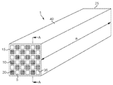
본 발명은 자동차 배기물과 같은, 배출물 처리 시스템에서 사용하기 위한 촉매 벽-유동형 모노리스에 관한 것이다. 미립자 필터에서 사용하기 위한 벽-유동형 모노리스는 관련 기술분야에 널리 공지되어 있다. 이는 배기 가스(미립자 물질 포함)의 유동이 다공성 재료로 형성된 벽을 통과하는 것을 강제함으로써 작업한다.The present invention relates to a catalytic wall-flow type monolith for use in an emission treatment system, such as an automobile exhaust. Wall-flow monoliths for use in particulate filters are well known in the art. This works by forcing the flow of exhaust gases (including particulate matter) to pass through a wall formed of a porous material.
모노리스는 바람직하게, 길이방향을 사이에 규정하는, 제1 면 및 제2 면을 갖는다. 사용 시에, 제1 면 및 제2 면 중 하나는 배기 가스를 위한 유입구 면일 것이고, 다른 하나는 처리된 배기 가스를 위한 배출구 면일 것이다.The monolith preferably has a first surface and a second surface defining a longitudinal direction therebetween. In use, one of the first and second faces will be the inlet face for the exhaust gas and the other will be the outlet face for the treated exhaust gas.
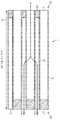
벽-유동형 모노리스에서 통상적인 바와 같이, 이는 길이방향으로 연장되는 제1 및 제2의 복수의 채널을 갖는다. 제1의 복수의 채널은 제1 면에서 개방되고 제2 면에서 폐쇄된다. 제2의 복수의 채널은 제2 면에서 개방되고 제1 면에서 폐쇄된다. 채널들이 바람직하게 서로 평행하여, 채널들 사이에서 일정한 벽 두께를 제공한다. 결과적으로, 복수의 채널 중 하나에 진입하는 가스는, 채널 벽을 통해서 다른 복수의 채널 내로 확산하지 않고는 모노리스를 빠져 나갈 수 없다. 채널은 채널의 개방 단부 내로 밀봉재 재료를 도입하는 것에 의해서 폐쇄된다. 바람직하게, 제1의 복수의 채널 내의 채널의 수는 제2의 복수의 채널 내의 채널의 수와 동일하고, 각각의 복수의 채널은 모노리스 전반을 통해서 균일하게 분포된다.As is common in wall-flow monoliths, it has first and second plurality of channels extending in the longitudinal direction. The first plurality of channels are open at the first side and closed at the second side. The second plurality of channels are open on the second side and closed on the first side. The channels are preferably parallel to each other, providing a constant wall thickness between the channels. As a result, the gas entering one of the plurality of channels can not escape the monolith without diffusing into the other plurality of channels through the channel walls. The channel is closed by introducing a sealing material into the open end of the channel. Preferably, the number of channels in the first plurality of channels is equal to the number of channels in the second plurality of channels, and each of the plurality of channels is uniformly distributed throughout the monolith.
바람직하게, 제1 및 제2의 복수의 채널의 유압 채널 직경은 1 내지 1.5 mm이고, 습윤된 둘레로 나눈 유동 면적의 4배로서 규정된다. 채널은 일정한 폭일 수 있고, 각각의 복수의 채널은 균일한 채널 폭을 가질 수 있다. 그러나, 바람직하게, 사용 시에 유입구로서의 역할을 하는 복수의 채널은, 배출구로서의 역할을 하는 복수의 채널보다, 더 큰 평균 횡단면 폭을 갖는다. 바람직하게, 차이가 적어도 10%이다. 이는 필터 내의 증가된 애쉬(ash) 저장 용량을 가능하게 하고, 이는 더 적은 재생 빈도수가 이용될 수 있다는 것을 의미한다. 채널의 습윤된 둘레는, SEM 또는 TEM과 같은 공지된 현미경 기술을 이용하여 측정될 수 있다.Preferably, the hydraulic channel diameter of the first and second plurality of channels is between 1 and 1.5 mm, and is defined as four times the flow area divided by the wetted perimeter. The channel may be of constant width, and each of the plurality of channels may have a uniform channel width. Preferably, however, the plurality of channels serving as the inlet in use have a larger average cross-sectional width than the plurality of channels serving as the outlet. Preferably, the difference is at least 10%. This allows an increased ash storage capacity in the filter, which means that less regeneration frequency can be used. The wetted perimeter of the channel can be measured using known microscopic techniques such as SEM or TEM.
바람직하게, 인접 채널들 사이의 기재의 평균 최소 두께는 8 내지 20 mil("밀은" 1/1000 인치이다)(0.02 내지 0.05 cm)이다. 이는 SEM 또는 TEM과 같은 알려진 현미경 기술을 이용하여 측정될 수 있다. 채널들은 바람직하게는 평행하고 바람직하게는 일정한 폭을 갖기 때문에, 인접 채널들 사이의 최소 벽 두께는 바람직하게는 일정하다. 인지되는 바와 같이, 재현가능한 측정을 보장하도록 평균 최소 거리를 측정하는 것이 필요하다. 예를 들어, 채널들이 원형 단면을 가지며 밀접하게 패킹되어 있으면, 2개의 인접 채널들 간에 벽이 가장 얇은 하나의 명백한 지점이 존재한다.Preferably, the average minimum thickness of the substrate between adjacent channels is from 8 to 20 mils ("mill" is 1/1000 inch) (0.02 to 0.05 cm). This can be measured using known microscopic techniques such as SEM or TEM. Since the channels are preferably parallel and preferably have a constant width, the minimum wall thickness between adjacent channels is preferably constant. As will be appreciated, it is necessary to measure the average minimum distance to ensure reproducible measurement. For example, if the channels have a circular cross section and are closely packed, there is one obvious point where the wall is thinnest between the two adjacent channels.
바람직하게, 길이방향에 수직인 평면 내에서, 모노리스는 평방 인치당 100 내지 500개의 채널(cpsi), 바람직하게 200 내지 400 cpsi를 갖는다. 예를 들어, 제1 면 상에서, 개방된 제1 채널 및 폐쇄된 제2 채널의 밀도는 제곱인치 당 200 내지 400개의 채널이다. 채널은 직사각형, 정사각형, 원형, 타원형, 삼각형, 육각형, 또는 다른 다각형 형상인 단면을 가질 수 있다.Preferably, in a plane perpendicular to the longitudinal direction, the monolith has 100 to 500 channels (cpsi) per square inch, preferably 200 to 400 cpsi. For example, on the first side, the density of the open first channel and the closed second channel is 200 to 400 channels per square inch. The channel may have a cross section that is rectangular, square, circular, elliptical, triangular, hexagonal, or other polygonal shape.
처리하고자 하는 가스의 채널 벽 통과를 용이하게 하기 위해, 모노리스는 다공성 기재로 형성된다. 기판은 또한 촉매 재료를 보유하기 위한 지지체로서 작용한다. 다공성 기재의 형성에 적합한 재료는 세라믹-유사 재료, 예컨대 근청석, 탄화규소, 질화규소, 지르코니아, 멀라이트(mullite), 스포듀민(spodumene), 알루미나-실리카-마그네시아 또는 지르코늄 실리케이트, 또는 다공성 내화성 금속을 포함한다. 벽-유동형 기재는 또한 세라믹 섬유 복합 재료로 형성될 수 있다. 바람직하게, 벽-유동형 기재는 근청석 및 규소 탄화물로 형성된다. 이러한 재료는 배기 스트림의 처리 시 직면하는 환경, 특히 고온을 견딜 수 있고, 충분히 다공성으로 제조될 수 있다. 이러한 재료, 및 다공성 모노리스 기판의 제조에서의 그의 용도는 관련 기술분야에 널리 공지되어 있다.In order to facilitate channel wall passage of the gas to be treated, the monolith is formed of a porous substrate. The substrate also serves as a support for holding the catalyst material. Suitable materials for forming the porous substrate include ceramic-like materials such as cordierite, silicon carbide, silicon nitride, zirconia, mullite, spodumene, alumina-silica-magnesia or zirconium silicate, . The wall-flowable substrate may also be formed of a ceramic fiber composite material. Preferably, the wall-flow type substrate is formed of cordierite and silicon carbide. Such a material can withstand the environment encountered in the treatment of the exhaust stream, especially at high temperatures, and can be made sufficiently porous. Such materials, and their use in the manufacture of porous monolith substrates, are well known in the art.
바람직하게, 코팅 전의 다공성 기재는, 30 내지 70%, 예를 들어 40 내지 65%, 가장 바람직하게 50% 초과, 예를 들어 55% 초과, 예를 들어 55 내지 70%의 다공도를 갖는다. 다공도 결정을 위한 적합한 기술이 당업계에 공지되어 있고 수은 다공도 측정법 및 x-레이 단층촬영법을 포함한다.Preferably, the porous substrate before coating has a porosity of from 30 to 70%, for example from 40 to 65%, most preferably greater than 50%, for example greater than 55%, for example from 55 to 70%. Suitable techniques for porosity determination are well known in the art and include mercury porosimetry and x-ray tomography.
바람직하게, 다공성 기재는 10 내지 30㎛, 예를 들어 13 내지 25㎛, 18 내지 23㎛, 15 내지 25㎛, 16 내지 21㎛ 또는 13 내지 23㎛ 범위의 평균 세공 크기를 포함할 수 있다. 다공성 기재의 평균 세공 크기를 결정하기 위한 적합한 기술이 당업계에 공지되어 있고 수은 다공도 측정법을 포함한다.Preferably, the porous substrate may comprise an average pore size in the range of 10 to 30 占 퐉, for example in the range of 13 to 25 占 퐉, 18 to 23 占 퐉, 15 to 25 占 퐉, 16 to 21 占 퐉 or 13 to 23 占 퐉. Suitable techniques for determining the average pore size of the porous substrate are known in the art and include mercury porosimetry.
본 발명은, 탄화수소, 질소 산화물, 및 일산화탄소와 같은 기체 배출물을 처리하는 것에 더하여 미립자를 포집하기 위해서, 가솔린 엔진, 특히 가솔린 직접 분사(GDI) 엔진 뿐만 아니라 주로 화학양론적으로 동작되는 가솔린 엔진과 함께 이용하기에 적합한 배기 시스템 및 구성요소에 관한 것이다. 특히, 본 발명은 삼원 촉매(TWC) 및 미립자 트랩을 포함하는 배기 처리 시스템에 관한 것이다. 즉, 미립자 트랩은 TWC 촉매 조성물을 내부에 구비한다.The present invention is directed to a gasoline engine, particularly a gasoline direct injection (GDI) engine, as well as a gasoline engine that is operated primarily stoichiometrically, in order to collect particulates in addition to treating gaseous emissions such as hydrocarbons, nitrogen oxides, and carbon monoxide To an exhaust system and components suitable for use. In particular, the invention relates to an exhaust treatment system comprising a three-way catalyst (TWC) and a particulate trap. That is, the particulate trap has a TWC catalyst composition therein.
모노리스는 삼원 촉매(TWC)를 포함한다. TWC는 당업계에 잘 알려져 있다. TWC는 실질적으로 다공성 기재 전반을 통해서 분포된다.The monolith includes a three-way catalyst (TWC). TWC is well known in the art. The TWC is distributed substantially throughout the porous substrate.
TWC 조성물은 일반적으로 워시코트 내에 제공된다. 층상형 TWC 촉매는 상이한 층들에 대해서 상이한 조성들을 가질 수 있다. 전형적으로, TWC 촉매는, 2.5 g/in3 이하의 부하 및 5 g/in3 이상의 총 부하를 가지는 워시코트 층을 포함할 수 있다. 미립자 트랩과 함께 이용하기 위해서, 배압 제약으로 인해서, TWC 촉매 워시코트 층은 바람직하게 1 g/in3 내지 0.1 g/in3, 바람직하게 0.7 g/in3 내지 0.25 g/in3, 그리고 가장 바람직하게 0.6 g/in3 내지 0.5 g/in3이다. 이는, 이산화탄소 및 탄화수소를 산화시킬 수 있는, 그리고 질소 산화물(NOx)을 감소시킬 수 있는 충분한 촉매 활성도를 제공한다.The TWC composition is typically provided in a washcoat. Layered TWC catalysts can have different compositions for different layers. Typically, TWC catalysts may comprise, 2.5 g / in 3 or less of the load, and 5 g / in the wash coat layer has a total of three or more load. Due to backpressure constraints, for use with particulate traps, the TWC catalyst washcoat layer preferably has a surface area of 1 g / in 3 to 0.1 g / in 3 , preferably 0.7 g / in 3 to 0.25 g / in 3 , 0.6 g / in 3 to 0.5 g / in 3 . This provides sufficient catalytic activity to oxidize carbon dioxide and hydrocarbons and to reduce nitrogen oxides (NOx).
도포는 "벽상의(on wall)" 도포 또는 "벽내의(in wall)" 도포로서 특성화될 수 있다. 전자는 채널 표면 상에의 코팅 층의 형성으로 특징지워진다. 후자는 다공성 재료 내부의 세공 내로의 촉매 재료의 침윤으로 특징지워진다. "벽내의" 또는 "벽상의" 도포를 위한 기술은 도포되는 재료의 점도, 도포 기술(예를 들어, 분무 또는 침지), 및 상이한 용매들의 존재에 따라 달라질 수 있다. 이러한 도포 기술은 관련 기술분야에 공지되어 있다. 워시코트의 점도는 예를 들어 그의 고형분 함량에 의해 영향을 받는다. 이는 또한 워시코트의 입자 크기 분포 - 상대적으로 평탄한 분포는, 입자 크기 분포가 날카로운 피크를 가지는 미세하게 밀링된 워시코트에 상이한 점도를 제공할 것이다 - 그리고 구아 검 및 다른 검과 같은 레올로지 개질제(rheology modifier)에 의해서 영향을 받는다. 적합한 코팅 방법이, 본원에서 참조로 포함되는, WO 2011/080525, WO 99/047260, WO 2014/195685 및 WO 2015/145122에 설명되어 있다.Application may be characterized as " on-wall " application or " in-wall " application. The former is characterized by the formation of a coating layer on the channel surface. The latter is characterized by the infiltration of the catalyst material into the pores inside the porous material. The techniques for " in-wall " or " on-the-wall " application may vary depending on the viscosity of the material being applied, the application technique (e.g., spraying or dipping) and the presence of different solvents. Such application techniques are well known in the art. The viscosity of the washcoat is affected, for example, by its solids content. This also suggests that the particle size distribution of the washcoat - a relatively flat distribution would provide different viscosities to the finely milled washcoat with a particle size distribution with sharp peaks - and rheology modifiers such as guar gum and other swords modifier. Suitable coating methods are described in WO 2011/080525, WO 99/047260, WO 2014/195685 and WO 2015/145122, which are incorporated herein by reference.
본원에서 설명된 모노리스는 다공성 기재 전반을 통해서 분포된 촉매 재료를 포함한다. 이러한 재료는, 예를 들어 워시코팅 방법을 이용한 침윤에 의해서, 기재의 세공 내에 포함된다. 이는 세공을 코팅하고 촉매 재료를 그 내부에 유지하는 한편, 가스가 채널 벽을 통해서 침투할 수 있게 하는 충분한 다공도를 유지한다.The monolith described herein comprises a catalytic material distributed throughout the porous substrate. Such a material is contained in the pores of the substrate, for example, by infiltration using a wash coating method. Which maintains a sufficient porosity to coat the pores and to retain the catalyst material therein while allowing gas to penetrate through the channel walls.
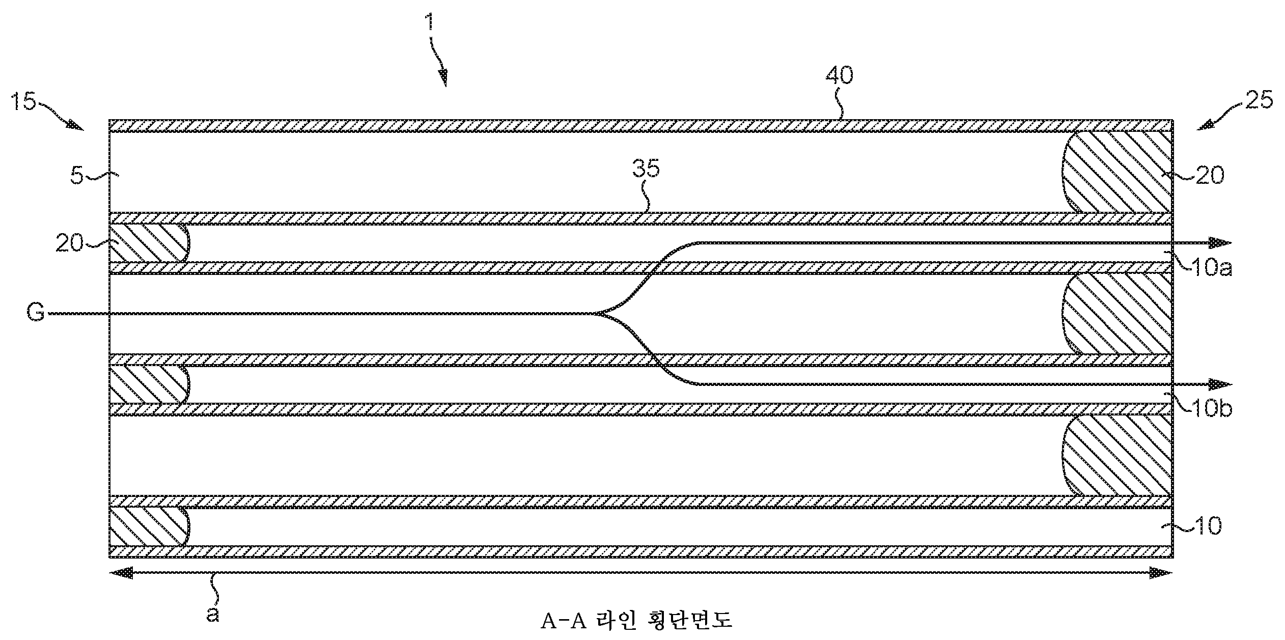
적어도 한 명의 발명자는 이제, 매우 놀랍게도, 특히 TWC 워시코트 성분의 D90을 조절함으로써 그리고 적절한 코팅 방법을 사용함으로써 벽상 웨지(on-wall wedge) 형상의 코팅 프로파일을 수득하는 것이 가능함을 발견하였고, 여기서 제1의 복수의 채널의 채널 벽 표면 상에 존재하는 벽상 코팅의 단위 부피당 하나 이상의 백금족 금속의 중량 기준의 양은 다공성 기재의 길이방향을 따라 계속적으로 변화되고; 및/또는 제1의 복수의 채널의 채널 벽 표면 상에 존재하는 벽상 코팅의 층 두께가 길이방향을 따라 계속적으로 변화한다. 이러한 코팅 배열은 TWC 활성도를 개선시킬 수 있고 및/또는 필터를 가로질러 배압을 감소(압력 강하라고도 지칭됨)시킬 수 있다.At least one inventor has now surprisingly found that it is possible to obtain a coating profile in the form of an on-wall wedge, especially by controlling the D90 of the TWC washcoat component and by using suitable coating methods, The amount based on the weight of the at least one platinum group metal per unit volume of the wall coating present on the channel wall surface of the plurality of channels of 1 is continuously varied along the length direction of the porous substrate; And / or the layer thickness of the wall coating present on the channel wall surface of the first plurality of channels continuously varies along the length direction. This coating arrangement can improve TWC activity and / or reduce back pressure across the filter (also referred to as pressure drop).
따라서, 본 발명의 제1 측면에서, (a) 제1의 복수의 채널의 채널 벽 표면 상에 존재하는 벽상 코팅의 단위 부피당 하나 이상의 백금족 금속의 중량의 양이 길이방향을 따라 연속적으로 변화될 수 있고; 및/또는 (b) 제1의 복수의 채널의 채널 벽 표면 상에 존재하는 벽상 코팅 - 또는 실질적으로 벽상 코팅 - 의 층 두께는 길이방향을 따라 연속적으로 변화될 수 있다.Thus, in a first aspect of the present invention there is provided a process for the preparation of (a) a process comprising the steps of (a) continuously varying the amount of one or more platinum group metal weights per unit volume of wall coating present on the channel wall surface of the first plurality of channels, Have; And / or (b) the wall thickness of the wall-like coating or substantially the wall-like coating present on the channel wall surface of the first plurality of channels can be continuously varied along the length direction.
다공성 기재는 길이방향을 그들 사이에서 규정하는 제1 면 및 제2 면, 및 길이방향으로 연장되어 있고 제1 복수 내면을 제공하는 적어도 제1의 복수의 채널을 갖는다. 사용 시에, 제1 면 및 제2 면 중 하나는 배기 가스를 위한 유입구 면일 것이고, 나머지는 처리된 배기 가스를 위한 배출구 면일 것이다. 모노리스가 길이방향으로 연장되어 있는 제2의 복수의 채널을 추가로 포함하고, 제1의 복수의 채널이 제1 면에서 개방되어 있고 제2 면에서 폐쇄되어 있으며 제1 복수 내면을 제공하고, 제2의 복수의 채널이 제2 면에서 개방되어 있고 제1 면에서 폐쇄되어 있으며 제2 복수 내면을 제공하고, 임의로 제2 복수 내면 상에 코팅이 추가로 제공되는 것인 벽-유동형 필터가 바람직하다. 벽-유동형 모노리스는 미립자 필터에서의 이용에 대해서 당업계에 잘 알려져 있다. 이는, (미립자 물질을 포함하는) 배기 가스의 유동이 다공성 재료로 형성된 벽을 통과하게 강제하는 것에 의해서 작업한다.The porous substrate has a first surface and a second surface defining a longitudinal direction therebetween, and at least a first plurality of channels extending in a longitudinal direction and providing a first plurality of inner surfaces. In use, one of the first and second faces will be the inlet face for the exhaust gas, and the remainder will be the outlet face for the treated exhaust gas. Wherein the first plurality of channels are open at the first surface and closed at the second surface and provide a first plurality of inner surfaces, 2 is open on the second side and closed on the first side and provides a second plurality of inner surfaces and optionally a coating on the second plurality of inner surfaces is further provided . Wall-flow monoliths are well known in the art for use in particulate filters. This works by forcing the flow of exhaust gas (including particulate matter) through a wall formed of a porous material.
코팅에 관해 본원에서 사용되는 "벽상" 또는 "실질적 벽상"에 대한 임의의 언급은, 촉매 성분의 50% 초과, 특히 촉매 성분의 60% 초과, 바람직하게는 촉매 성분의 70% 초과(예를 들어, 촉매 성분의 80% 초과), 보다 바람직하게는 촉매 성분의 90% 초과가 벽(즉, 필터 기재)의 표면 상에 배치되도록, 촉매 재료를 포함하는 액체가 벽의 표면 상에 코팅되어 있는 벽-유동형 필터 기재를 지칭한다. 액체가 복수의 촉매 성분을 포함하면, 전형적으로 모든 촉매 성분의 50% 초과, 특히 모든 촉매 성분의 60% 초과, 바람직하게는 모든 촉매 성분의 70% 초과(예를 들어, 모든 촉매 성분의 80% 초과), 보다 바람직하게는 모든 촉매 성분의 90% 초과가 벽의 표면 상에 배치된다.Any reference to a "wall" or "substantial wall" as used herein with respect to a coating is intended to encompass more than 50% of the catalyst component, especially more than 60% of the catalyst component, preferably more than 70% , More than 80% of the catalyst component), more preferably more than 90% of the catalyst component is disposed on the surface of the wall (i.e., the filter substrate) - refers to a flow-through filter substrate. If the liquid comprises a plurality of catalyst components, typically more than 50% of all catalyst components, especially more than 60% of all catalyst components, preferably more than 70% of all catalyst components (e.g., 80% , More preferably more than 90% of all catalyst components are disposed on the surface of the wall.
코팅에 관해 본원에서 사용되는 "벽내" 또는 "실질적 벽내"에 대한 임의의 언급은, 촉매 성분의 50% 초과, 특히 촉매 성분의 60% 초과, 바람직하게는 촉매 성분의 70% 초과(예를 들어, 촉매 성분의 80% 초과), 보다 바람직하게는 촉매 성분의 90% 초과가 벽(즉, 필터 기재) 내부에 배치되도록, 촉매 재료를 포함하는 액체가 벽의 표면 상에 코팅되어 있는 벽-유동형 필터 기재를 지칭한다. 액체가 복수의 촉매 성분을 포함하면, 전형적으로 모든 촉매 성분의 50% 초과, 특히 모든 촉매 성분의 60% 초과, 바람직하게는 모든 촉매 성분의 70% 초과(예를 들어, 모든 촉매 성분의 80% 초과), 보다 바람직하게는 모든 촉매 성분의 90% 초과가 벽의 내부에 배치된다. 100% 미만의 벽내 또는 실질적 벽내 코팅의 임의의 값에 대해, 나머지 분량은 벽상 코팅으로서 적절한 기술, 예를 들어 SEM을 사용하여 가시화될 것이고, 그러한 것으로서 벽상 코팅 두께를 가질 것이다. 벽내 코팅이 채널 벽 표면에서 가시화되는 경우, 이는 통상 제1 또는 제2 채널 벽 표면 중 어느 하나 또는 둘 다의 표면에서 보일 것이다. 그러나, 코팅을 벽내 삽입하도록 의도되고, 이와 같은 목적을 위해 코팅은 가능한 벽내에 전부 우선적으로 수용되도록 배열됨을 이해할 것이다. 벽내 위치를 촉진할 수 있는 파라미터는, 졸 성분의 밀링 또는 선택에 의해 바람직하게는 5 ㎛ 미만으로 적절한 D90을 선택하는 것, 및 벽내 다공도가 과충전되어 벽내 코팅의 유출을 독려하지 않도록 적절한 촉매 부하량을 선택하여 벽상에 있게 하는 것을 포함한다.Any reference to "in-wall" or "substantially in-wall" as used herein with respect to the coating means that more than 50% of the catalyst component, especially more than 60% of the catalyst component, preferably more than 70% , More preferably greater than 80% of the catalyst component), more preferably more than 90% of the catalyst component is disposed within the wall (i.e., filter substrate) Filter substrate. If the liquid comprises a plurality of catalyst components, typically more than 50% of all catalyst components, especially more than 60% of all catalyst components, preferably more than 70% of all catalyst components (e.g., 80% , More preferably more than 90% of all catalyst components are disposed inside the walls. For any value of less than 100% intrinsic or substantially intrinsic coating, the remaining amount will be visualized using a suitable technique such as SEM as a wall coating, and will have a wall coating thickness as such. If the in-wall coating is visible on the channel wall surface, it will typically be visible on the surface of either or both of the first or second channel wall surfaces. However, it is contemplated that the coating is intended to be intrathecally inserted, and for this purpose it will be understood that the coating is arranged to be wholly preferentially received within the possible walls. The parameters that can promote the in-wall location are selected by milling or selecting the sol component, preferably by a suitable D90 of less than 5 [mu] m, and by suitable catalyst loading such that the intragranular porosity is overcharged, And selecting it to be on the wall.
액체 촉매 워시코트 D90(부피)는 0.4 ㎛ 초과의 미립자 크기(즉, 일차적인 입자 크기)를 가질 수 있다. 바람직하게, 입자의 적어도 90%는 0.5 ㎛ 초과, 더 바람직하게 1 ㎛ 초과, 그리고 보다 더 바람직하게 2 ㎛ 초과의 입자 크기를 갖는다.The liquid catalyst washcoat D90 (volume) may have a particle size (i.e., primary particle size) of greater than 0.4 microns. Preferably, at least 90% of the particles have a particle size of greater than 0.5 [mu] m, more preferably greater than 1 [mu] m, and even more preferably greater than 2 [mu] m.
액체 중 입자의 적어도 90%는 25 ㎛ 미만의 입자 크기(즉, 일차적인 입자 크기)를 가질 수 있다. 바람직하게, 입자의 적어도 90%는 20 ㎛ 미만, 더 바람직하게 15 ㎛ 미만, 그리고 보다 더 바람직하게 10 ㎛ 미만의 입자 크기를 갖는다.At least 90% of the particles in the liquid may have a particle size of less than 25 [mu] m (i.e., a primary particle size). Preferably, at least 90% of the particles have a particle size of less than 20 microns, more preferably less than 15 microns, and even more preferably less than 10 microns.
입자 크기 측정은 맬버른 마스터사이저(Malvern Mastersizer) 2000을 사용하여 레이저 회절 입자 크기 분석에 의해 수득되며, 이는 부피-기반 기술이고 (즉, D(v, 0.1), D(v, 0.5), D(v, 0.9) 및 D(v, 0.98)은 각각 DV10, DV50, DV90 및 DV98(또는 각각 D10, D50, D90 및 D98)로도 지칭될 수 있음), 수학적 미(Mie) 이론 모델을 적용하여 입자 크기 분포를 결정한다. 희석된 워시코트 샘플은 35 와트에서 30초 동안 계면활성제 없이 증류수에서 초음파처리에 의해 제조되었다.Particle size measurements were obtained by laser diffraction particle size analysis using a Malvern Mastersizer 2000, which is a volume-based technique (i.e., D (v, 0.1) (v, 0.9) and D (v, 0.98) may also be referred to as DV10, DV50, DV90 and DV98 (or D10, D50, D90 and D98 respectively) The size distribution is determined. The diluted washcoat samples were prepared by ultrasonication in distilled water without surfactant at 35 watts for 30 seconds.
코팅의 단위 면적 당 제1 백금족 금속의 중량 기준의 양 및/또는 제2 백금족 금속의 중량 기준의 양은 길이방향을 따라 계속적으로 변화될 수 있다. 이는 코팅의 밀도를 변화시킴으로써, 또는 백금족 금속의 용액을 벽-유동형 모노리스 필터 상에 코팅된 내화성 금속 산화물의 층 내로 흡상시킴으로써 달성될 수 있으나, 길이방향의 코팅 두께를 변화시킴으로써 보다 용이하게 달성될 수 있다.The amount based on the weight of the first platinum group metal and / or the amount based on the weight of the second platinum group metal per unit area of the coating can be continuously varied along the length direction. This can be achieved by varying the density of the coating, or by sucking a solution of the platinum group metal into the layer of refractory metal oxide coated on the wall-flow type monolith filter, but can be achieved more easily by varying the coating thickness in the longitudinal direction have.
바람직하게는, 코팅 중의 제1 및/또는 제2 백금족 금속의 중량 기준의 양은 길이방향을 따라 코팅 내에서 선형적으로 변화될 수 있다. 즉, 양에서의 변화의 구배가 일정하게 유지된다.Preferably, the amount by weight of the first and / or second platinum group metal in the coating can be varied linearly in the coating along the length direction. That is, the gradient of the change in the amount is kept constant.
본 발명에 따른 촉매 모노리스 필터에서, 길이방향의 제1 복수 표면 상에 존재하는 촉매 재료의 최대 벽상 코팅 두께는 최대 150 마이크로미터일 수 있다. 벽-유동형 필터 채널은 전형적으로 적어도 1개의 측면을 포함한다(예를 들어, 정사각형 단면 또는 육각형 단면을 가짐). 채널이 적어도 1개의 플랫(flat) 측면을 갖는 단면 형상을 갖는 경우, 본 발명에 따라, 벽상 코팅의 두께는 단면 형상의 코너들 사이의 중간 지점에서 예를 들어 SEM에 의해 측정된다.In a catalytic monolith filter according to the present invention, the maximum wall coating thickness of the catalytic material present on the first plurality of longitudinal surfaces may be up to 150 micrometers. The wall-flow filter channel typically includes at least one side (e.g., having a square cross-section or a hexagonal cross-section). If the channel has a cross sectional shape with at least one flat side, according to the invention, the thickness of the wall coating is measured, for example by SEM, at an intermediate point between the corners of the cross sectional shape.
바람직하게는 코팅은 10 내지 150 마이크로미터, 보다 바람직하게는 50 내지 100 마이크로미터의 두께를 갖는다.Preferably, the coating has a thickness of 10 to 150 micrometers, more preferably 50 to 100 micrometers.
바람직하게는 제1 및 제2 층 중 적어도 하나의 두께는 길이방향을 따라 10 내지 100 마이크로미터, 보다 바람직하게는 20 내지 50 마이크로미터 만큼 변화한다. 즉, 층은 제1 채널의 길이를 따라 0에서 50 마이크로미터까지 증가할 수 있다.Preferably, the thickness of at least one of the first and second layers varies from 10 to 100 micrometers along the length, more preferably from 20 to 50 micrometers. That is, the layer may increase from 0 to 50 micrometers along the length of the first channel.
바람직하게는, 제1의 복수의 채널의 채널 벽 표면 상에 존재하는 최대 층 두께 및/또는 하나 이상의 백금족 금속의 최대 중량은 제1의 복수의 채널의 개방 단부에 있다. 용어 "웨지-형상의 프로파일"은 본원에서 상기 규정과 상호교환적으로 사용된다.Preferably, the maximum layer thickness present on the channel wall surface of the first plurality of channels and / or the maximum weight of the at least one platinum group metal is at the open end of the first plurality of channels. The term " wedge-shaped profile " is used herein interchangeably with the above definitions.
바람직하게는, 제2의 복수의 채널의 벽 표면 상에 층 두께를 갖는 촉매 재료를 포함하는 벽상 코팅이 추가로 제공되고,Preferably, a wall coating is further provided which comprises a catalytic material having a layer thickness on the wall surface of the second plurality of channels,
여기서 층 두께를 갖는 촉매 재료를 포함하는 벽상 코팅은 제2의 복수의 채널의 채널 벽 표면 상에 존재하고,Wherein a wall coating comprising a catalytic material having a layer thickness is present on a channel wall surface of a second plurality of channels,
제2의 복수의 채널의 채널 벽 표면 상의 촉매 재료는 (i) 로듐(Rh) 단독; (ii) 팔라듐(Pd) 단독; (iii) 백금(Pt) 및 로듐(Rh); (iv) 팔라듐(Pd) 및 로듐(Rh); 및 (v) 백금(Pt), 팔라듐(Pd) 및 로듐(Rh)으로 이루어진 군으로부터 선택된 하나 이상의 백금족 금속 및 내화성 금속 산화물 지지체를 포함하며, 여기서,The catalyst material on the channel wall surface of the second plurality of channels comprises (i) rhodium (Rh) alone; (ii) palladium (Pd) alone; (iii) platinum (Pt) and rhodium (Rh); (iv) palladium (Pd) and rhodium (Rh); And (v) at least one platinum group metal and a refractory metal oxide support selected from the group consisting of platinum (Pt), palladium (Pd), and rhodium (Rh)
(i) 제2의 복수의 채널의 채널 벽 표면 상에 존재하는 벽상 코팅의 단위 부피당 하나 이상의 백금족 금속의 중량 기준의 양이 길이방향을 따라 계속적으로 변화하고/거나,(i) the amount by weight of at least one platinum group metal per unit volume of wall coating present on the channel wall surface of the second plurality of channels continuously varies along the length direction and /
(ii) 제2의 복수의 채널의 채널 벽 표면 상에 존재하는 벽상 코팅의 층 두께가 길이방향을 따라 계속적으로 변화한다.(ii) the layer thickness of the wall coating present on the channel wall surface of the second plurality of channels continuously varies along the length direction.
실시예 4에 기재된 추가의 대안에서, 제1의 복수의 채널 또는 제2의 복수의 채널을 통해 적용되는 적어도 하나의 워시코트 조성의 D90을 조절함으로써, 실질적 벽내 코팅을 포함하는 생성물을 수득하는 것이 가능하고, 제1의 복수의 채널의 제1 벽상 코팅에 추가로 제1의 복수의 채널에 층 두께를 갖는 촉매 재료를 포함하는 제2 벽상 코팅이 존재하며, 여기서 실질적 벽내 코팅 및 제1의 복수의 채널의 제2 벽상 코팅의 촉매 재료는 (i) 로듐(Rh) 단독; (ii) 팔라듐(Pd) 단독; (iii) 백금(Pt) 및 로듐(Rh); (iv) 팔라듐(Pd) 및 로듐(Rh); 및 (v) 백금(Pt), 팔라듐(Pd) 및 로듐(Rh)으로 이루어진 군으로부터 선택된 백금족 금속 중 하나 이상 및 내화성 금속 산화물 지지체를 포함하며, 제1의 복수의 채널의 제1 벽상 코팅에 추가로 제1의 복수의 채널의 제2 벽상 코팅에서,In a further alternative described in Example 4, it is possible to obtain a product comprising a substantial intraluminal coating by adjusting the D90 of at least one washcoat composition applied through the first plurality of channels or the second plurality of channels There is a second wall coating comprising a catalyst material having a layer thickness in a first plurality of channels in addition to a first wall coating of a first plurality of channels, The catalyst material of the second wall coating of the channel comprises (i) rhodium (Rh) alone; (ii) palladium (Pd) alone; (iii) platinum (Pt) and rhodium (Rh); (iv) palladium (Pd) and rhodium (Rh); And (v) at least one of a platinum group metal selected from the group consisting of platinum (Pt), palladium (Pd) and rhodium (Rh) and a refractory metal oxide support, In the second wall coating of the first plurality of channels,
(i) 제1의 복수의 채널의 채널 벽 표면 상에 존재하는 벽상 코팅의 단위 부피당 하나 이상의 백금족 금속의 중량 기준의 양이 길이방향을 따라 계속적으로 변화하고/거나,(i) the amount by weight of at least one platinum group metal per unit volume of wall coating present on the channel wall surface of the first plurality of channels continuously varies along the length direction and /
(ii) 제1의 복수의 채널의 채널 벽 표면 상에 존재하는 제2 벽상 코팅의 층 두께가 길이방향을 따라 계속적으로 변화한다.(ii) the layer thickness of the second wall coating present on the channel wall surface of the first plurality of channels continuously varies along the length direction.
대안적으로, 제1의 복수의 채널의 채널 벽 표면 및 제2의 복수의 채널의 채널 벽 표면에 의해 규정된 채널 벽은 다공성이고, 이는 촉매 재료를 포함하는 제2 벽내(또는 실질적 벽내) 코팅을 포함하며, 여기서 벽내 촉매 재료는 (i) 로듐(Rh) 단독; (ii) 팔라듐(Pd) 단독; (iii) 백금(Pt) 및 로듐(Rh); (iv) 팔라듐(Pd) 및 로듐(Rh); 및 (v) 백금(Pt), 팔라듐(Pd) 및 로듐(Rh)으로 이루어진 군으로부터 선택된 하나 이상의 백금족 금속 및 내화성 금속 산화물 지지체를 포함하고, 촉매 재료를 포함하는 벽내(또는 실질적 벽내) 코팅은 제1의 복수의 채널의 채널 벽 표면 상에 존재하는 벽상 코팅 중에 포함된 촉매 재료와 동일하거나 또는 상이하다.Alternatively, the channel wall defined by the channel wall surface of the first plurality of channels and the channel wall surface of the second plurality of channels is porous, which is coated in a second wall (or substantially within the wall) Wherein the in-wall catalyst material comprises (i) rhodium (Rh) alone; (ii) palladium (Pd) alone; (iii) platinum (Pt) and rhodium (Rh); (iv) palladium (Pd) and rhodium (Rh); And (v) at least one platinum group metal and a refractory metal oxide support selected from the group consisting of platinum (Pt), palladium (Pd) and rhodium (Rh) 1 is the same as or different from the catalyst material contained in the wall coating present on the channel wall surface of the plurality of channels.
제2의 복수의 채널의 채널 벽 표면 상에 존재하는 최대 층 두께 및/또는 하나 이상의 백금족 금속의 최대 중량은 바람직하게는 제2의 복수의 채널의 개방 단부에 있다. 제1의 복수의 채널의 제2 벽상 코팅에 존재하는 최대 층 두께 및/또는 하나 이상의 백금족 금속의 최대 중량은 바람직하게는 제1의 복수의 채널의 폐쇄 단부에 있다.The maximum layer thickness present on the channel wall surface of the second plurality of channels and / or the maximum weight of the at least one platinum group metal is preferably at the open end of the second plurality of channels. The maximum layer thickness present in the second wall coating of the first plurality of channels and / or the maximum weight of the at least one platinum group metal is preferably at the closed end of the first plurality of channels.
TWC는 알루미나, 바람직하게 감마-알루미나를 포함한다. 이러한 것은 유리한 캐리어 재료인데, 이는 그것이 큰 표면적을 가지기 때문이고 내화성 금속 산화물이기 때문이다. 다시 말해서, 알루미나는 내화 지지 재료로서의 역할을 한다. 이는, 필터가, 직면되는 고온 조건에서 요구되는 양호한 열 용량을 가지게 한다.The TWC comprises alumina, preferably gamma-alumina. This is an advantageous carrier material, because it has a large surface area and is a refractory metal oxide. In other words, alumina serves as a refractory support material. This allows the filter to have the required good heat capacity at the high temperature conditions encountered.
TWC는 또한 하나 이상의 백금족 금속(예를 들어, 백금, 팔라듐, 로듐, 레늄, 및 이리듐)을 포함한다. 이들은 양호한 활성도 및 긴 수명을 나타낸다. 바람직하게, 하나 이상의 백금족 금속은 Pt, Pd 및 Rh, 또는 그 둘 이상의 조합으로부터 선택된다. 백금족 금속은 배기 가스의 정화에 필요한 반응에 촉매 작용을 하는 역할을 한다.TWCs also include one or more platinum group metals (e.g., platinum, palladium, rhodium, rhenium, and iridium). They exhibit good activity and long life. Preferably, the at least one platinum group metal is selected from Pt, Pd and Rh, or a combination of two or more thereof. The platinum group metal serves to catalyze the reaction required to purify the exhaust gas.
바람직하게, 백금족 금속은 Pt, Pd 및 Rh; Pd 및 Rh; 또는 단지 Pd; 또는 단지 Rh이다.Preferably, the platinum group metals are Pt, Pd and Rh; Pd and Rh; Or only Pd; Or just Rh.
NOx 환원은 O2가 없을 때 가장 효과적인 반면, CO 및 탄화수소의 감소는 O2를 요구한다. 3개의 성분 모두를 변환시키기 위해서, TWC에 진입하는 배기 가스는 "화학양론적 지점"(14.7:1 공기-대-연료(AFR) 질량비)에 근접하여야 한다. 공기-연료 당량비인, λ(람다)는 주어진 공기/연료 혼합물에 대한 실제 AFR 대 화학양론의 비율이다. 화학양론에서 λ = 1.0이고, 부화(rich) 혼합물(과다 산화 종(species)에서 미연소 탄화수소(HC) 및 CO와 같은 환원 종을 생성하는 혼합물)에서 λ은 1.0 미만이고, 즉 14.7:1 미만의 AFR이며, 그리고 희박 혼합물에서 λ는 1 초과, 즉 14.7:1 초과의 AFR이다. 3개의 NOx, CO 및 HC 모두의 동시적인 촉매 변환이 발생되는 좁은 창 만이 존재한다.NOx reduction is most effective in the absence of O 2 , while reduction of CO and hydrocarbons requires O 2 . To convert all three components, the exhaust gas entering the TWC should be close to the "stoichiometric point" (14.7: 1 air-to-fuel (AFR) mass ratio). The air-fuel equivalence ratio, lambda (lambda), is the ratio of the actual AFR to the stoichiometry for a given air / fuel mixture. Lambda = 1.0 in stoichiometry and lambda is less than 1.0 in a rich mixture (mixture that produces unburned hydrocarbons (HC) and reducing species such as CO in excess oxidizing species), i.e. less than 14.7: 1 , And in the lean mixture, [lambda] is greater than 1, i.e., greater than 14.7: 1. There is only a narrow window where simultaneous catalytic conversion of all three NOx, CO and HC occurs.
산소 센서가 희망 창 내에서 AFR을 유지하기 위해서 가능한 한 많은 피드백을 제공하지만, 그러한 피드백은 화학양론적 지점 주위에서 교란을 유발하고, 이는 촉매가 약간 부화 및 약간 희박 조건을 교번적으로 찾으려 한다는 것을 의미한다. 동적 운전 중에, 예를 들어 급가속은, 피드백 메커니즘이 제어를 다시 획득할 수 있기 전에, 배기 가스를 부화(enrich)시킬 수 있기 때문이다. 유사하게, 운전자가 가속기 페달에서 발을 뗄 때, 연료 차단(fuel cut)이 과다하게 희박한 배기 가스를 초래할 수 있다. 그에 따라, 가능한 한 완전한 삼원 변환 활성도를 달성하기 위해서, 부화 동작될 때, 미반응 CO 및 HC를 소모하기 위해서, TWC가 적은 양의 O2를 제공할 필요가 있다. 역으로, 배기 가스가 약간 산화적이 될 때, 과다 O2가 소모될 필요가 있다.While the oxygen sensor provides as much feedback as possible to maintain the AFR within the window of hope, such feedback causes disturbances around the stoichiometric point, which suggests that the catalyst will seek to alternate slightly hatching and slightly lean conditions it means. During dynamic operation, for example, rapid acceleration can enrich the exhaust gas before the feedback mechanism can regain control. Similarly, when the driver releases his / her foot from the accelerator pedal, fuel cuts can result in excessively lean exhaust gases. Thus, in order to achieve the full three-way conversion activity as much as possible, the TWC needs to provide a small amount of O 2 to consume unreacted CO and HC when incubated. Conversely, when the exhaust gas becomes slightly oxidative, excessive O 2 needs to be consumed.
따라서, TWC는 또한 산소 저장 성분(OSC)을 포함한다. 이는 다가-원자가 상태를 갖는 실체이고, 산화 조건 하에 산소 또는 아산화질소와 같은 산화제와 활발하게 반응할 수 있거나, 또는 환원 조건 하에 일산화탄소(CO) 또는 수소와 같은 환원제와 반응한다. 적합한 산소 저장 성분의 예는, 바람직하게 혼합 산화물 또는 복합 산화물 내의 하나 이상의 부가적인 산화물로 안정화된, 세리아를 포함한다. OSC로서 프라세오디미아가 포함될 수도 있다. OSC의 워시코트 층으로의 전달은 예를 들어 혼합 산화물의 사용에 의해 달성될 수 있다. 예를 들어, 세리아는 세륨 및 지르코늄의 혼합 산화물, 및/또는 세륨, 지르코늄 및 네오디뮴의 혼합 산화물에 의해 전달될 수 있다. 예를 들어, 프라세오디미아는 프라세오디뮴 및 지르코늄의 혼합 산화물, 및/또는 프라세오디뮴, 세륨, 란타넘, 이트륨, 지르코늄 및 네오디뮴의 혼합 산화물에 의해 전달될 수 있다.Thus, the TWC also contains an oxygen storage component (OSC). It is an entity with a multivalent-valence state and can actively react with oxidizing agents such as oxygen or nitrous oxide under oxidizing conditions or react with a reducing agent such as carbon monoxide (CO) or hydrogen under reducing conditions. Examples of suitable oxygen storage components include ceria preferably stabilized with one or more additional oxides in the mixed oxide or composite oxide. As the OSC, praseodymia may be included. The transfer of the OSC to the washcoat layer can be achieved, for example, by the use of mixed oxides. For example, ceria may be delivered by mixed oxides of cerium and zirconium, and / or mixed oxides of cerium, zirconium and neodymium. For example, praseodymia can be delivered by mixed oxides of praseodymium and zirconium, and / or mixed oxides of praseodymium, cerium, lanthanum, yttrium, zirconium and neodymium.
OSC는 하나 이상의 혼합 산화물을 포함하거나 그러한 것으로 구성된다. 바람직하게, OSC는, 선택적으로 하나 이상의 희토류 원소를 포함하는, 세리아 및 지르코니아 혼합 산화물을 포함한다.The OSC comprises or consists of one or more mixed oxides. Preferably, the OSC comprises ceria and zirconia mixed oxides, optionally including one or more rare earth elements.
세리아 및 지르코니아를 포함하는 혼합 산화물은 파이로클로르(pyrochlore) 구조, 즉 A2B2O7, 또는 유사 구조, 예컨대 무질서 플루오라이트([AB]2O7) 또는 소위 델타 (δ)-상 (A4B3O12)를 가질 수 있으며, 여기서 "A"는 3가 양이온을 나타내고, "B"는 4가 양이온을 나타낸다. 이러한 재료는 비교적 낮은 표면적(예를 들어, 15 m2/g 미만) 및 비교적 높은 벌크 밀도를 갖지만, 우수한 산소 저장 및 방출 특성을 갖는다. 고 벌크 밀도 OSC 성분을 사용하면, 유사한 산소 저장/방출 활성을 갖는 보다 전형적인 OSC 세리아-지르코니아 혼합 산화물과 비교해서 본 발명에 따른 감소된 배압 필터를 초래할 수 있다.The mixed oxide comprising ceria and zirconia may have a pyrochlore structure, i.e. A 2 B 2 O 7 , or a similar structure, such as disordered fluorite ([AB] 2 O 7 ) or so-called delta A 4 B 3 O 12 ), wherein "A" represents a trivalent cation and "B" represents a tetravalent cation. These materials have relatively low surface area (e.g., less than 15 m 2 / g) and relatively high bulk density, but have excellent oxygen storage and release characteristics. Using a high bulk density OSC component can result in a reduced backpressure filter according to the present invention as compared to more typical OSC ceria-zirconia mixed oxides having similar oxygen storage / release activities.
적어도 한 발명자는 세륨 및 지르코늄의 프라세오디뮴-도핑된 혼합 산화물이 제1의 복수의 채널 내의 촉매 재료의 그을음 산화를 촉진시킨다는 것을 발견하였다. 따라서 바람직하게는, 제1의 복수의 채널이 예를 들어 미립자 물질을 생성하는 가솔린 직접 분사 엔진용 시스템에서 OSC를 포함하는 경우, 제1의 복수의 채널은, 바람직하게 가솔린 미립자 물질과 접촉되는 벽 코팅 내에 또는 벽 코팅 상에서, 프라세오디뮴을 포함하는 OSC를 포함한다. 이와 관련하여, 프라세오디뮴은 혼합 산화물의 총 함량을 기준으로 2 내지 10 wt%로 존재할 수 있다.At least one inventor has found that the praseodymium-doped mixed oxide of cerium and zirconium promotes soot oxidation of the catalytic material in the first plurality of channels. Thus, preferably, where the first plurality of channels comprises, for example, an OSC in a system for a gasoline direct injection engine that produces particulate matter, the first plurality of channels preferably comprise a wall contacting the gasoline particulate material OSC containing praseodymium in the coating or on the wall coating. In this connection, praseodymium may be present in an amount of 2 to 10 wt% based on the total content of the mixed oxide.
임의의 이론에 얽매이고자 하는 의도 없이, 이하 실시예에서 제시된 실험 결과로부터, 본 발명자들은 프라세오디뮴의 그을음 연소 촉진 효과는 직접 촉매 효과(예를 들어, 프라세오디뮴이 그을음과 접촉)와는 관련이 없는 것으로 생각된다. 오히려, 본 발명자들은 상기 효과는 세륨 성분에 의한 그을음 산화의 촉진과 관련되는 것으로 생각된다. 특히, 본 발명자는, 관찰된 그을음 연소 효과의 개선은 세륨의 4+/3+ 산화환원 상태 간의 산소 베이컨시(vacancy) 및 관련 유출 산소를 통해 고체 벌크 내 확산되는 산소 음이온의 해리의 촉진 및 세리아-지르코니아 고용체의 입방 플루오라이트 구조에 대한 프라세오디뮴의 준안정화 효과와 관련됨을 제안한다.Without intending to be bound by any theory, from the experimental results presented in the following examples, the present inventors believe that the soot combustion promoting effect of praseodymium is not related to direct catalytic effect (e.g., praseodymium contacts soot) . Rather, we believe that this effect is associated with the acceleration of soot oxidation by the cerium component. In particular, the inventors have found that the improvement in the observed soot burning effect is due to the oxygen vacancy between the 4 + / 3 + redox state of cerium and the acceleration of dissociation of the oxygen anion diffusing into the solid bulk through the associated effluent oxygen, - zirconia solid solution is related to the metastable effect of praseodymium on the cubic fluorite structure.
OSC 대 알루미나의 중량비는 바람직하게는 65:35 내지 85:15, 보다 바람직하게는 70:30 내지 80:20, 가장 바람직하게는 약 75:25이다. TWC가 별도의 유닛으로서 제공되는 경우 알루미나 및 OSC를 대충 50:50 비율로 제공하는 것이 통상적이지만, 본 발명자들은 조합된 미립자 필터 및 촉매 처리 유닛을 제공하는 경우, 약 75:25의 비율이 훨씬 더 우수한 공정 효율을 제공한다는 것을 발견하였다. 특히, 추가의 산소 저장 용량은 디바이스가 기재에 접착 불능이거나 또는 기능하기에 불충분한 열질량 없이, 개시에서부터 전(full) 온도까지 광범위한 조건에 걸쳐 작동하는 것을 가능케 한다. 산소 저장 용량의 개선의 결과로서, 대부분의 조건 하 NOx 전환이 개선된다. OSC:알루미나의 상한 85:15를 초과하면, 코팅이 지나치게 열적으로 불안정하여 효과적으로 기능할 수 없는 것으로 밝혀졌다.The weight ratio of OSC to alumina is preferably 65:35 to 85:15, more preferably 70:30 to 80:20, and most preferably about 75:25. While it is customary to provide alumina and OSC at a roughly 50:50 ratio when the TWC is provided as a separate unit, the present inventors have found that when providing a combined particulate filter and a catalyst processing unit, Thereby providing excellent process efficiency. In particular, the additional oxygen storage capacity allows the device to operate over a wide range of conditions, from initiation to full temperature, without the thermal mass being insoluble or insufficient to function on the substrate. As a result of improved oxygen storage capacity, NO x conversion is improved under most conditions. Exceeding the upper limit of OSC: alumina of 85:15, the coating was found to be too thermally unstable and unable to function effectively.
바람직하게, TWC는 다공성 기재 전반에 걸쳐 균질하다. 즉, TWC 내의 성분의 상대적인 농도는 바람직하게 다공성 기재의 세공 전반을 통해서 일정하다.Preferably, the TWC is homogeneous throughout the porous substrate. That is, the relative concentration of components within the TWC is preferably constant throughout the pores of the porous substrate.
TWC는 바람직하게, 제1 및 제2의 복수의 채널 중 적어도 하나의 표면 상에서 코팅으로서 더 존재한다. 바람직하게, TWC는 미립자 트랩의 유입구 측 및 배출구측 모두에 코팅된다.The TWC is preferably further present as a coating on the surface of at least one of the first and second plurality of channels. Preferably, the TWC is coated on both the inlet side and the outlet side of the particulate trap.
추가적인 측면에 따라, 연소 배기 가스의 유동을 처리하기 위한 배출물 처리 시스템이 제공되고, 그러한 시스템은 본원에서 개시된 바와 같은 촉매 벽-유동형 모노리스를 포함한다.According to a further aspect, there is provided an effluent treatment system for treating the flow of combustion exhaust gas, the system comprising a catalyst wall-flowable monolith as disclosed herein.
배기 시스템은, 본 발명에 따른 촉매 벽-유동형 모노리스 필터의 상류 또는 하류에 배치되고 허니콤(honeycomb) 모노리스(관통형) 기재에 적용되는 TWC 조성과 같은 추가의 성분을 포함할 수 있다. 상류 또는 하류 TWC에서, 미연소 기상 및 비-휘발성 탄화수소(휘발성 유기 분획물) 및 일산화탄소는 대부분 연소되어 이산화탄소 및 물을 형성한다. 또한, 질소 산화물은 환원되어 질소 및 물을 형성한다. 산화 촉매를 사용하여 VOF의 상당 비율을 제거하면, 특히, 본 발명에 따른 하류 필터 상의 미립자 물질의 지나치게 많은 침착(즉, 막힘)을 방지하는데 도움이 된다.The exhaust system may include additional components such as the TWC composition disposed upstream or downstream of the catalyst wall-flow type monolith filter according to the present invention and applied to a honeycomb monolith (penetrating) substrate. In the upstream or downstream TWC, unburned gaseous and non-volatile hydrocarbons (volatile organic fractions) and carbon monoxide are mostly burned to form carbon dioxide and water. Also, the nitrogen oxides are reduced to form nitrogen and water. Removing a significant proportion of the VOF using an oxidation catalyst helps to prevent excessive deposition (i.e., clogging) of particulate matter on the downstream filter, in particular according to the present invention.
경우에 따라, 배기 시스템은 또한 추가의 성분을 포함할 수 있다. 예를 들어, 특히 희박 연소 엔진에 적용가능한 배기 시스템에서는, 허니콤 모노리스(관통형) 기재에 적용되는 상류 TWC 조성에 추가로 또는 그 대신에 본 발명에 따른 필터의 상류에 NOx 트랩이 배치될 수 있다. NOx 트랩(NOx 흡수체 촉매(NAC)라고도 공지됨)은 예를 들어 미국 특허 제5,473,887호로부터 공지되어 있으며, 희박 주행 모드 작동 동안 희박(산소 부화) 배기 가스(람다 >1)로부터 질소 산화물(NOx)을 흡착하고, 배기 가스 중의 산소 농도가 감소할 때(화학량론적 또는 부화 주행 모드) NOx를 탈착하도록 설계된다. 탈착된 NOx는, NAC의 하류에 위치하거나 또는 NAC 자체의 촉매 성분, 예컨대 로듐 또는 세리아에 의해 촉진되는 적합한 환원제, 예를 들어 가솔린 연료에 의해 N2로 환원될 수 있다.Optionally, the exhaust system may also include additional components. For example, in an exhaust system that is particularly applicable to lean burn engines, in addition to or instead of the upstream TWC composition applied to the honeycomb monolith (penetrating) substrate, a NO x trap is disposed upstream of the filter according to the present invention . NO x traps (also known as NO x absorber catalysts (NAC)) are known, for example, from U.S. Patent No. 5,473,887, and include nitrogen oxides (NO x ) from lean (oxygen enrichment) NO x ) and desorb NO x when the oxygen concentration in the exhaust gas decreases (stoichiometric or hatching mode). The desorbed NO x can be reduced to N 2 by a suitable reducing agent, such as gasoline fuel, located downstream of the NAC or promoted by the catalytic component of the NAC itself, such as rhodium or ceria.
NAC의 하류에 SCR 촉매가 배치되어 NAC의 배출구를 수용하고, 환원제로서 암모니아를 사용하여 질소 산화물을 환원시켜 질소 및 물을 형성하는 선택적 촉매 환원 촉매에 의해 NAC로 생성되는 임의의 암모니아의 배출물 처리를 추가로 제공할 수 있다. 적합한 SCR 촉매는, 예를 들어 구리 및/또는 철 또는 그의 산화물에 의한 이온 교환으로 촉진되는 분자체, 특히 알루미노실리케이트 제올라이트, 바람직하게는 국제 제올라이트 협회(International Zeolite Association)에 따른 CHA, AEI, AFX 또는 BEA 프레임워크 유형을 갖는 것을 포함한다.An SCR catalyst is disposed downstream of the NAC to receive the outlet of the NAC and the exhaust of any ammonia produced by the NAC by the selective catalytic reduction catalyst that forms nitrogen and water by reducing the nitrogen oxides using ammonia as the reducing agent Can be provided. Suitable SCR catalysts are, for example, zeolites, especially aluminosilicate zeolites promoted by ion exchange with copper and / or iron or its oxides, preferably CHA, AEI, AFX according to the International Zeolite Association Or having the BEA framework type.
본 발명은 또한, 본 발명의 제2 측면에 따른 배기 시스템을 포함하는 본원에 기재된 바와 같은 포지티브 점화 엔진을 포함할 수 있다. 부가적으로, 본 발명은 본 발명에 따른 엔진을 포함하는 차량, 예컨대 승용차를 포함할 수 있다.The present invention may also include a positive ignition engine as described herein including an exhaust system according to the second aspect of the present invention. Additionally, the present invention may include a vehicle including an engine according to the present invention, such as a passenger car.
추가적인 측면에 따라, 촉매 벽-유동형 모노리스의 제조 방법이 제공되고, 그러한 방법은:According to a further aspect, there is provided a process for producing a catalyst wall-flowable monolith, comprising:
길이방향을 사이에서 규정하는 제1 면 및 제2 면, 그리고 길이방향으로 연장되어 있는 제1 및 제2의 복수의 채널을 갖는 다공성 기재를 제공하는 단계로서, 여기서 제1의 복수의 채널은 제1 면에서 개방되어 있고 제2 면에서 폐쇄되어 있으며, 제2의 복수의 채널은 제2 면에서 개방되어 있고 제1 면에서 폐쇄되어 있는 단계;Providing a porous substrate having a first side and a second side defining a longitudinal direction therebetween and a first and a second plurality of channels extending in a longitudinal direction, The second plurality of channels being open at the second side and being closed at the first side;
촉매 재료를 포함하는 워시코트로 다공성 기재를 침윤시키는 단계; 및Infiltrating the porous substrate with a washcoat comprising a catalytic material; And
다공성 기재 내의 촉매 재료를 하소시키는 단계를 포함하고,And calcining the catalyst material in the porous substrate,
촉매 재료는:The catalyst material is:
(i) 알루미나;(i) alumina;
(ii) 하나 이상의 백금족 금속; 및(ii) one or more platinum group metals; And
(iii) 산소 저장 성분(OSC)을 포함하고,(iii) an oxygen storage component (OSC)
OSC는 세리아, 또는 세륨을 포함하는 하나 이상의 혼합 산화물을 포함하고, 65:35 내지 85:15의 OSC 대 알루미나의 중량비로 존재한다.The OSC comprises at least one mixed oxide comprising ceria, or cerium, and is present in a weight ratio of OSC to alumina of 65:35 to 85:15.
바람직하게, 전술한 방법에 따라 제조된 촉매 벽-유동형 모노리스는 본원에서 설명된 바와 같은 모노리스이다. 즉, 제1 측면의 모든 특징이 본원에서 설명된 추가적인 측면과 자유롭게 조합될 수 있다.Preferably, the catalyst wall-flowable monolith prepared according to the method described above is a monolith as described herein. That is, all features of the first aspect can be freely combined with the additional aspects described herein.
바람직하게, 다공성 기재 침윤 전의 워시코트의 준비는, Pt, Pd 및/또는 Rh를 알루미나와 혼합하는 것, 그리고 촉매 재료의 제1 부분을 형성하기 위해서 하소시키는 것을 포함한다. 본 발명자는, 이러한 처리가 백금족 금속을 미리-고정하는 역할을 한다는 것을 발견하였다.Preferably, the preparation of the washcoat prior to porous substrate infiltration comprises mixing Pt, Pd and / or Rh with alumina, and calcining to form a first portion of the catalyst material. The present inventors have found that this treatment serves to pre-fix the platinum group metals.
바람직하게, 다공성 기재 침윤 전의 워시코트의 준비는, Rh를 OSC와 혼합하는 것, 그리고 촉매 재료의 제2 부분을 형성하기 위해서 하소시키는 것을 포함한다. 본 발명자는, 이러한 처리가 유사하게 백금족 금속을 미리-고정하는 역할을 한다는 것을 발견하였다. 이는, 로듐이 알루미나와 접촉될 때 관찰될 수 있는 로듐의 비활성화를 방지한다.Preferably, the preparation of the washcoat prior to the porous substrate infiltration comprises mixing Rh with OSC and calcining to form a second portion of the catalyst material. The inventors have discovered that this treatment similarly serves to pre-immobilize platinum group metals. This prevents inactivation of rhodium that can be observed when rhodium is contacted with alumina.
본 발명은, 종래 기술 방법의 다수 층 아니라, 단일 도포 단계에서의 TWC의 제공을 허용한다. 그에 따라, 이는 프로세스 복잡성 및 큰 배압을 방지한다.The present invention allows the provision of TWCs in a single application step, rather than multiple layers of prior art methods. This, in turn, prevents process complexity and large back pressure.
웨지-형상의 벽상 프로파일을 가지는 촉매 벽-유동형 모노리스는 개시된 방법의 적합화에서 수득될 수 있다. 영국 특허 공개 제2524662호(그의 전체 내용이 본원에 참조로 포함됨)에는, (a) 미리 결정된 양의 액체를 필터 기재의 상부 단부에서 격납 수단 내로 도입하는 단계; 및 (b) 액체를 격납 수단으로부터 필터 기재 내로 배수시키는 단계를 포함하는, 복수 채널을 포함하는 필터 기재의 코팅 방법이 개시되어 있다. 상기 방법은 기재의 채널 벽 표면 상에 막 유형 코팅과 같은 벽상 코팅을 형성시키는데 적합하다.A catalytic wall-flow type monolith having a wedge-shaped wall-like profile can be obtained from the adaptation of the disclosed method. GB 2524662 (the entirety of which is incorporated herein by reference) discloses a method of making a filter comprising: (a) introducing a predetermined amount of liquid into the containment means at the upper end of the filter substrate; And (b) draining the liquid from the containment means into the filter substrate. The method is suitable for forming a wall coating, such as a film-type coating, on the channel wall surface of the substrate.
영국 특허 공개 제2524662호에 개시된 방법에서는, 비교적 낮은 점도가 사용되고, 바람직하게는 증점제가 첨가되지 않는다. 예를 들어, 상기 방법에서는 액체가 5 내지 100 cP, 예컨대 10 내지 100 cP, 특히 20 내지 90 cP, 바람직하게는 25 내지 80 cP, 더욱 더 바람직하게는 35 내지 65 cP(20℃에서 50 rpm 스핀들 속도로 SC4-27 스핀들을 사용하여 브룩필드(Brookfield) RV DVII+ 엑스트라 프로(Extra Pro) 점도계 상에서 측정 시)의 점도를 갖는 것이 바람직하다. 액체는 중력 하에 액체가 필터 기재 내로 점진적으로 배수되는 것을 가능케 하는 점도를 갖는다.In the process disclosed in GB-A-2524662, a relatively low viscosity is used, preferably no thickening agent is added. For example, in the process described above, the liquid may have a viscosity of from 5 to 100 cP, such as from 10 to 100 cP, especially from 20 to 90 cP, preferably from 25 to 80 cP, even more preferably from 35 to 65 cP (Measured on a Brookfield RV DVII + Extra Pro viscometer using an SC4-27 spindle at a speed of from about < RTI ID = 0.0 > 20 C) < / RTI > The liquid has a viscosity that allows the liquid to be gradually drained into the filter base under gravity.
일반적으로, 진공은 -0.5 내지 -50 kPa(대기압 미만), 특히 -1 내지 -30 kPa, 바람직하게는 -5 내지 -20 kPa이다(예를 들어, 필터 기재에 가해지는 진공). 진공은 0.25 내지 15초, 예컨대 0.5 내지 35초, 바람직하게는 1 내지 7.5초(예를 들어, 2 내지 5초) 동안 연속적으로 적용될 수 있다. 일반적으로, 높은 진공 강도 및/또는 더 긴 진공 지속시간이 더 높은 비율의 벽내 코팅을 초래한다.Generally, the vacuum is between -0.5 and -50 kPa (subatmospheric pressure), especially between -1 and -30 kPa, preferably between -5 and -20 kPa (e.g. vacuum applied to the filter substrate). The vacuum may be applied continuously for 0.25 to 15 seconds, such as 0.5 to 35 seconds, preferably 1 to 7.5 seconds (e.g., 2 to 5 seconds). Generally, high vacuum strength and / or longer vacuum durations result in higher rates of intralayer coating.
적어도 한명의 발명자는 고점도 액체, 즉, 100 cP 초과의 슬러리 또는 워시코트를 사용함으로써 길이방향을 따라 계속적으로 변화하는 벽상 코팅(또는 실질적 벽상 코팅)의 층 두께를 달성하는 것이 가능함을 발견하였다. 이 배열은 첨부된 실시예에 나타낸 바와 같은 유의한 이점을 갖는다.At least one inventor has found that it is possible to achieve a layer thickness of a wall coating (or substantially a wall coating) that continuously varies along the length direction by using a high viscosity liquid, i.e., a slurry or wash coat in excess of 100 cP. This arrangement has significant advantages as shown in the appended examples.
추가적인 측면에 따라, 본 발명은, 질소 산화물(NOx), 일산화탄소(CO), 미연소 탄화수소 연료(HC) 및 미립자 물질(PM)을 포함하는, 포지티브 점화 내연 기관으로부터의 연소 배기 가스를 처리하는 방법을 제공하고, 그러한 방법은 배기 가스를 본 발명의 제1 측면에 따른 촉매 벽 유동 필터와 접촉시키는 것을 포함한다.According to a further aspect, the present invention provides a method of treating combustion exhaust gas from a positive ignition internal combustion engine, comprising nitrogen oxide (NOx), carbon monoxide (CO), unburned hydrocarbon fuel (HC) and particulate matter The method comprising contacting the exhaust gas with a catalyst wall flow filter according to the first aspect of the present invention.
이제, 본 발명을 하기 비-제한적 도면과 관련하여 기재할 것이며, 여기서,
도 1a는 본 발명에 따른 벽-유동형 모노리스 필터(1)를 개략적으로 나타내는 사시도이고;
도 1b는 도 1a에 나타낸 벽-유동형 모노리스 필터(1)의 A-A 라인 단면도이고;
도 2는 가솔린 직접 분사 엔진용 배기 가스 처리 시스템의 개략도를 나타낸다.The present invention will now be described with reference to the following non-limiting drawings,
1A is a perspective view schematically showing a wall-flow
1B is an AA line cross-sectional view of the wall-flow
Figure 2 shows a schematic diagram of an exhaust gas treatment system for a gasoline direct injection engine.
본 발명에 따른 벽-유동형 모노리스(1)는 도 1a 및 도 1b에 나타나 있다. 이는 모노리스(1)의 길이방향(도 1a에서 양방향 화살표 "a"로 나타냄)으로 서로 평행하게 배열된 다수의 채널을 포함한다. 다수의 채널은 제1 서브세트의 채널(5) 및 제2 서브세트의 채널(10)을 포함한다.The wall-
채널은 제2 서브세트의 채널(10)이 제1 서브세트의 채널(5)보다 더 좁도록 묘사되어 있다. 이는 필터에서 증가된 애쉬/그을음 저장 용량을 제공하는 것으로 밝혀졌다. 그러나, 대안적으로, 채널은 실질적으로 동일한 크기일 수 있다.The channel is depicted such that the
제1 서브세트의 채널(5)은 벽-유동형 모노리스(1)의 제1 단부 면(15) 상의 단부 부분에서 개방되어 있고, 제2 단부 면(25) 상의 단부 부분에서 밀봉 재료(20)로 밀봉되어 있다.The
한편, 제2 서브세트의 채널(10)은 벽-유동형 모노리스(1)의 제2 단부 면(25) 상의 단부 부분에서 개방되어 있고, 제1 단부 면(15) 상의 단부 부분에서 밀봉 재료(20)로 밀봉되어 있다.On the other hand, the second subset of
벽-유동형 모노리스(1)에는 채널 벽(35)의 세공 내부에 촉매 재료가 제공되어 있다. 이는 명세서 내 다른 부분에 논의 및 관련 기술분야에 공지된 바와 같이 워시코트 적용 방법으로 제공될 수 있다.The wall-flowable monolith (1) is provided with a catalyst material inside the pores of the channel wall (35). This may be provided in a washcoat application method as is known in the art and discussed elsewhere in the specification.
따라서, 벽-유동형 모노리스가 배기 시스템에서 사용되는 경우, 제1 서브세트의 채널(5)에 도입되는 배기 가스(G)(도 1b에서, "G"는 배기 가스를 가리키고, 화살표는 배기 가스의 유동 방향을 가리킴)는 채널(5a)과 채널(10a 및 10b) 사이에 개재된 채널 벽(35)을 통과한 다음 모노리스(1)로부터 유출될 것이다. 따라서, 배기 가스 중의 미립자 물질은 채널 벽(35)에 의해 포획된다.Thus, when a wall-flow monolith is used in the exhaust system, the exhaust gas G introduced into the first subset of channels 5 (in Fig. 1B, "G" refers to the exhaust gas, Flow direction) will flow out of the
모노리스(1)의 채널 벽(35)에서 지지된 촉매는 배기 연기를 처리하기 위한 촉매로서의 기능을 한다.The catalyst supported in the
도 2에 나타낸 배기 가스 처리 시스템(100)의 실시양태에서, 배기 가스(110)의 유동은 벽-유동형 모노리스(1)를 통과한다. 배기 가스(110)는 엔진(115)에서부터 덕팅(ducting)(120)을 통해 배기 시스템(125)으로 보내진다.In the embodiment of the exhaust
벽-유동형 모노리스는 본원에 단일 구성요소로서 기재되어 있음을 참고하여야 한다. 그럼에도 불구하고, 배출물 처리 시스템을 형성할 때, 사용된 모노리스는 본원에 기재된 바와 같은 복수의 더 작은 모노리스를 함께 부착함으로써 또는 복수 채널을 함께 부착함으로써 형성될 수 있다. 이러한 기술 뿐만 아니라 배출물 처리 시스템의 적합한 케이싱 및 구성은 관련 기술분야에 널리 공지되어 있다.It should be noted that the wall-flowable monolith is described herein as a single component. Nevertheless, when forming the emission treatment system, the monolith used can be formed by attaching a plurality of smaller monoliths as described herein, or by attaching a plurality of channels together. As well as these techniques, suitable casing and construction of the emission treatment system are well known in the art.
이제, 촉매 벽-유동형 모노리스를 하기 비-제한적 실시예와 관련하여 추가로 기재할 것이다.Now, the catalytic wall-flow type monolith will be further described with respect to the following non-limiting embodiments.
실시예Example
실시예 1(비교예)Example 1 (Comparative Example)
4개의 벽-유동형 필터(4 Х 5" 및 600/4 셀 밀도)를, 40[g/ft-3]/0:9:1 [Pt:Pd:Rh 중량비]의 백금족 금속(PGM) 조성을 갖는 TWC로 코팅하였다. 각 TWC는 상이한 중량비의 Al2O3 대 CeZrO4를 포함하였다.Four wall-flow filters (4 × 5 "and 600/4 cell density) were fabricated with a platinum group metal (PGM) composition of 40 [g / ft -3 ] / 0: 9: 1 [Pt: Pd: Rh weight ratio] It was coated with a TWC. each TWC is comprised a different weight ratio of Al 2 O 3 dae CeZrO 4.
필터를 벤치(bench) 탑재된 실험실 V8 랜드 로버(Land Rover) 가솔린 터보 직접 분사(GTDI) 엔진의 배기 시스템에 끼우고, 80 시간 동안 반복된, 10초의 (운전자가 가속기 페달에서 발을 떼는 것을 시뮬레이트하여, 희박 배기 가스의 "스파이크(spike)"를 생성하기 위한) 연료 차단과 그에 이어지는 람다 1에서의 180초(5% 람다 진폭 및 5초 스위치 타임으로 630℃ 유입구 온도에서의 교란된 화학량론적 동작)를 포함하는 독점권이 부여된 실험 방법을 사용하여 시효시켰다.The filter was placed in a bench-mounted laboratory V8 Land Rover gasoline turbo direct injection (GTDI) engine exhaust system and simulated for 10 seconds (80 seconds), simulating the driver stepping off the accelerator pedal (To generate a " spike " of lean exhaust gas), followed by 180 seconds at lambda 1 (5% lambda amplitude and 5 second switch time to disturb stoichiometric operation at 630 & ) Using an exclusively granted experimental method.
이어서, 450℃ 필터 유입구 온도 및 130 kg/h 질량 유동, 4% 람다 진폭 및 0.991 내지 1.01의 람다 설정점에서 유로 5 배출 표준에 인증된 2.0 리터 GTDI(가솔린 터보 직접 분사) 실험실 벤치-탑재된 엔진을 사용하여, 시효된 샘플에 대해 람다 스윕(sweep) 실험을 수행하였다. 더 큰 값은 더 우수한 변환 활성도를 나타낸다. 결과를 이하의 표에 기재하였다. 본 발명에 따른 필터가 종래 필터보다 더 높은 CO/NOx 크로스-오버(Cross-Over) 점을 갖는다는 것, 즉 더 활성적이라는 것을 알 수 있다.Then, a 2.0 liter GTDI (gasoline turbo direct injection) laboratory bench-mounted engine certified to a
결과는 다음과 같다.The results are as follows.

표로부터 알 수 있는 바와 같이, CeZrO4:Al2O3 비율을 1:1 초과로 높이는 것은, 코팅된 관통-유동 모노리스의 NOx 변환 능력에 유해하다는 것이 발견되었다.As can be seen from the table, it was found that raising the CeZrO 4 : Al 2 O 3 ratio above 1: 1 is detrimental to the NO x conversion ability of the coated through-flow monoliths.
실시예 2Example 2
4개의 벽-유동형 필터(4.66 x 4.5" 및 300/8 셀 밀도)에 PGM 60/0.57:3를 가지는 TWC를 코팅하였다. 각 TWC는 상이한 중량비의 Al2O3 대 CeZrO4를 포함하였다. 코팅된 필터는 하소되었고 시효되었다(열수, 10% H2O 첨가된 공기 내의 1100℃, 5h).Four wall-flow filters (4.66 x 4.5 " and 300/8 cell densities) were coated with TWC having PGM 60 / 0.57: 3. Each TWC contained a different weight ratio of Al 2 O 3 to CeZrO 4 . The filter was calcined and aged (1100 ° C, 5 h in hot, 10% H 2 O-added air).
1.4l GTDI 실험 엔진을 사용하여, NOx 배출을 표준 엔진 실험에 기반하여 측정하였다. 결과는 다음과 같다:Using a 1.4l GTDI experimental engine, NOx emissions were measured based on standard engine experiments. The results are as follows:

표로부터 알 수 있는 바와 같이, CeZrO4:Al2O3 중량비가 1:2로부터 3:1로 증가됨에 따라, 상대적인 NOx 배출이 감소된다.As can be seen from the table, CeZrO4: Al 2 O 3 weight ratio is 1: 3 from 2: 1 in accordance with the increased, is reduced relative to NOx emissions.
실시예 3Example 3
3개의 벽-유동형 필터(4.66 x 4.5" 및 300/8 셀 밀도)에 PGM 22/0:20:2를 가지는 TWC를 코팅하였다. 각 TWC는 상이한 중량비의 Al2O3 대 CeZrO4를 포함하였다. 코팅된 필터를 실시예 2에서와 같이 하소하였고 시효처리 하였다.Three TWCs with PGM 22/0: 20: 2 were coated on three wall-flow filters (4.66 x 4.5 " and 300/8 cell densities). Each TWC contained a different weight ratio of Al 2 O 3 to CeZrO 4 The coated filter was calcined and aged as in Example 2.
2.0l GTDI 엔진 벤치 실험 엔진을 사용하여, NOx 배출을 표준 엔진 실험에 기반하여 측정하였다. 결과는 다음과 같다:Using a 2.0l GTDI engine bench test engine, NOx emissions were measured based on standard engine experiments. The results are as follows:

벽-유동형 필터를 TWC 조성물로 코팅하기 위해, 다공성 기재를 기재의 상단이 슬러리 표면 바로 위쪽에 위치하도록 소정 분량의 촉매 슬러리에 수직으로 침지시켰다. 이와 같은 방식으로, 슬러리는 각 허니콤 벽의 유입구 면과 접촉하지만, 각 벽의 배출구 면과 접촉하는 것은 방지된다. 샘플을 슬러리 중에 약 30초 동안 방치시킨다. 필터를 슬러리에서 꺼내고, 과잉의 슬러리는 먼저 채널로부터 배수시킨 후 압축 공기로 블로잉(슬러리 침투 방향의 반대쪽으로)한 다음 슬러리 침투 방향으로부터 진공을 풀링(pulling)함으로써 벽-유동형 필터로부터 제거한다. 이와 같은 기술을 사용함으로써, 촉매 슬러리가 필터의 벽을 침투하지만, 세공은 완성된 필터에 과도한 배압이 축적될 정도까지는 막히지 않는다. 본원에서 사용된 바와 같이, 본원에 사용되는 "침투"라는 용어는, 필터 상의 촉매 슬러리의 분산을 설명할 때, 촉매 조성물이 필터의 벽 전반에 걸쳐 분산됨을 의미한다.To coat the wall-flow filter with the TWC composition, the porous substrate was immersed vertically in a predetermined amount of the catalyst slurry so that the top of the substrate was positioned just above the slurry surface. In this manner, the slurry contacts the inlet surface of each honeycomb wall, but is prevented from contacting the outlet surface of each wall. The sample is left in the slurry for about 30 seconds. The filter is removed from the slurry and the excess slurry is first drained from the channel and then blown with compressed air (to the opposite side of the slurry infiltration direction) and then removed from the wall-flow filter by pulling the vacuum from the slurry infiltration direction. By using such a technique, the catalyst slurry permeates the walls of the filter, but the pores are not clogged to such an extent that excessive back pressure builds up in the finished filter. As used herein, the term " penetration " as used herein means that the catalyst composition is dispersed throughout the walls of the filter when describing the dispersion of the catalyst slurry on the filter.
코팅된 필터는 전형적으로 약 100℃에서 건조되고, 더 높은 온도(예를 들어, 300 내지 450℃ 및 550℃ 이하)에서 하소된다. 하소 후, 촉매 부하량은 필터의 코팅 및 비-코팅된 중량의 계산을 통해 결정될 수 있다. 관련 기술분야의 통상의 기술자에게 명백한 바와 같이, 촉매 부하량은 코팅 슬러리의 고형분 함량을 변화시킴으로써 변경될 수 있다. 대안적으로, 코팅 슬러리 중의 필터의 반복적 침지를 수행한 후, 상기 기재된 바와 같은 과잉의 슬러리의 제거를 수행할 수 있다.Coated filters are typically dried at about 100 캜 and calcined at higher temperatures (e.g., 300 to 450 캜 and 550 캜 or less). After calcination, the catalyst loading can be determined through the coating of the filter and the calculation of the non-coated weight. As is apparent to one of ordinary skill in the relevant art, the catalyst loading can be varied by varying the solids content of the coating slurry. Alternatively, after performing repeated immersion of the filter in the coating slurry, removal of excess slurry as described above may be performed.
실시예 4 -그을음 연소 실험Example 4 - Soot burning experiment
각각 하기 표에 나타낸 조성을 가지며 희토류 원소로 도핑된 2종의 세리아-지르코니아 혼합 산화물을 CATLAB-PCS 결합된 마이크로반응기 및 질량 분광계 실험실 장치(하이든 애널리티컬(Hiden Analytical))를 사용하여 그의 그을음 연소 활성도에 대해 실험하였다. 근청석 샘플을 대조군으로서 실험하였다. 세리아-지르코니아 혼합 산화물 및 근청석 대조군을 500℃에서 2시간 동안 예비-연소시켰다.Two ceria-zirconia mixed oxides each having a composition shown in the following table and doped with a rare earth element were subjected to a CATLAB-PCS coupled microreactor and a mass spectrometer laboratory apparatus (Hiden Analytical) Respectively. The cordierite sample was tested as a control. Ceria-zirconia mixed oxide and cordierite control were pre-burned at 500 ° C for 2 hours.
유로 IV 배출 기준을 만족시키도록 인증된 유럽 커먼 레일 경량 디젤 2.2 리터 용량 엔진의 엔진으로부터 그을음을 수집하였다. 배기 시스템은 알루미늄 티타네이트 벽-유동형 필터를 포함하는 상업적으로 입수가능한 그을음 필터를 포함하였다. 그을음은 필터 상에 수집되었고, 압축 공기를 건(gun)으로부터 필터의 배출구 채널을 통해 안내함으로써 필터로부터 그을음을 제거하였다.Soot was collected from an engine of a European Common Rail lightweight diesel 2.2 liter capacity engine certified to meet Euro IV emission standards. The exhaust system included a commercially available soot filter including an aluminum titanate wall-flow filter. The soot was collected on the filter and the soot was removed from the filter by guiding the compressed air from the gun through the outlet channel of the filter.
샘플을 제조하기 위해, 85 mg의 각각의 샘플 또는 근청석과 15 mg의 그을음을 믹스가 균일한 색이고 덩어리 및 스트리크(streak)가 없을 때까지 막자(pestle) 및 막자사발(mortar)을 사용하여 혼합하였다. 막자사발의 벽으로부터 케이크를 주기적으로 벗겨냈다. 전처리는 수행하지 않았다.To prepare the sample, mix 85 mg of each sample or cordierite and 15 mg of soot using a pestle and mortar until there is no uniform color and no lumps and streaks And mixed. Periodically peeled the cake from the wall of the mullet bowl. No pretreatment was performed.
0.1 g의 각각의 샘플/그을음 혼합물(명목적으로 15 mg 그을음 함유)을 CATLAB 마이크로반응기 튜브 내로 넣었다. 이를 10℃/min의 온도 램프(ramp) 비율로 13% O2/He에서 가열하였다. 배출구 가스를 질량 분광계에 의해 모니터링하였다.0.1 g of each sample / soot mixture (containing 15 mg soot for purposes) was placed in a CATLAB microreactor tube. This was heated at 13% O 2 / He at a ramp rate of 10 ° C / min. The outlet gas was monitored by a mass spectrometer.
동일한 분쇄 배치로부터 취한 미세 근청석(250 ㎛ 미만)과 함께 분쇄된 그을음의 3개의 샘플을 가동하여 방법의 반복성을 평가하였다. 진화된 CO2 프로파일의 형상 및 그을음 산화 피크 위치에 대해 매우 우수한 반복성이 수득되었다. 실험 방법의 재현성은 또한 2명의 상이한 과학자가 동일한 혼합 그을음/세리아-지르코니아 혼합 산화물 재료를 제조함으로써 조사하였다. 보다 높은 온도에서 산화의 차이가 관찰되었지만, 아마도 그을음 및 혼합 산화물 간의 불량한 접촉 또는 600℃에서 비촉진된 그을음 산화 때문에, 양쪽 혼합물에 대한 주요 산화 피크는 예리하고, 잘 규정되고, 동일한 온도에 있다. 따라서, 상기 방법은 재현가능하고, 주요 피크 온도는 샘플 산화 활성도를 나타낸다.The repeatability of the method was evaluated by running three samples of ground soot along with fine cordierite (less than 250 [mu] m) taken from the same grinding batch. Very good repeatability was obtained for the shape of the evolved CO 2 profile and the soot oxidation peak position. The reproducibility of the experimental method was also investigated by two different scientists producing the same mixed soot / ceria-zirconia mixed oxide material. Although differences in oxidation were observed at higher temperatures, the main oxidation peak for both mixtures was sharp, well defined, and at the same temperature, probably due to poor contact between soot and mixed oxide or unaccelerated soot oxidation at 600 ° C. Thus, the method is reproducible and the main peak temperature indicates the sample oxidation activity.
그을음 산화에 대한 결과는 하기 표에 기술되어 있고, 이로부터, 샘플 A가 샘플 B와 유사한 조성을 가짐에도 불구하고, 5 중량% Pr6O11을 포함하는 샘플 B는 샘플 A보다 2.5% 더 낮은 그을음 산화 온도를 가짐을 알 수 있다. 본 발명자들은 필터의 유입구 채널 상의 벽상 코팅에 샘플 A를 함유시켜 그을음과 코팅 간의 접촉을 증가시키면, 더 낮은 배기 가스 온도에서 그을음의 제거를 유익하게 촉진시킬 것으로 결론지었다.The results for soot oxidation are described in the table below, so that although Sample A has a composition similar to Sample B, Sample B containing 5 wt% Pr 6 O 11 is 2.5 wt% lower than Sample A Oxidation temperature. The inventors concluded that the inclusion of Sample A in the wall coating on the inlet channel of the filter would advantageously promote the removal of soot at lower exhaust gas temperatures by increasing the contact between the soot and the coating.
표table
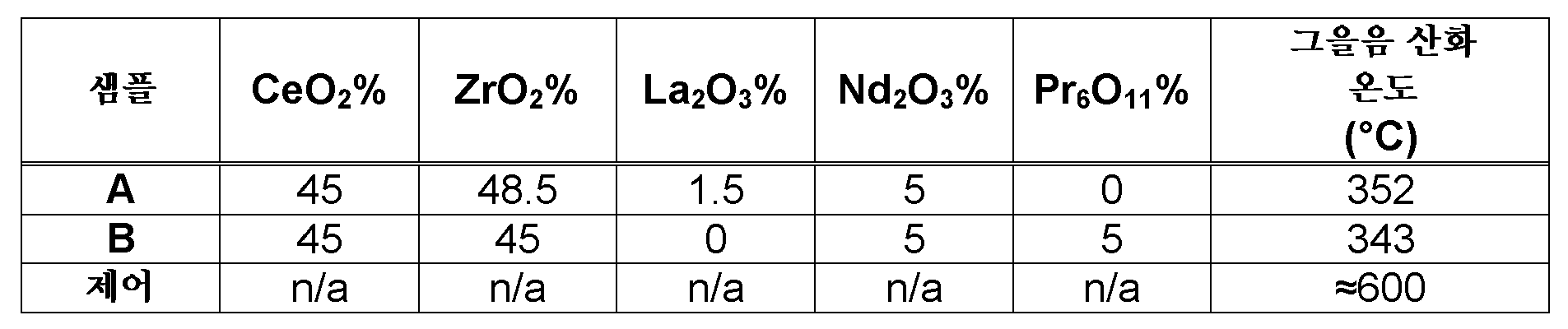
실시예 5Example 5
4.66 인치(직경) × 6 인치(길이)의 치수, 셀 밀도/벽 두께 300/8(제곱인치 당 셀 수/mil(1/1000 인치의 채널 벽 두께)), 및 완전 제형화된 삼원 촉매 워시코트를 갖는 기재에 기초하여 벽-유동형 필터를 제조하였고, 상기 완전 제형화된 삼원 촉매 워시코트는 Pd/Rh를 10 g/ft3에서 70:30 중량비로 포함하고 또한 세리아-지르코니아 기반 혼합 산화물 OSC 및 알루미나-기반 내화성 산화물 지지체를 1.6 g/in3의 부하량으로 포함하며, 상기 부하량은 제1의 복수의 채널 및 제2의 복수의 채널 간에 50:50 분할된다. 워시코트는 2 내지 4 마이크로미터의 D50 및 10 마이크로미터 미만의 D90을 포함하였다. 사용된 워시코트 고형분은 19%였고, 이는 통상의 기술자에게 공지된 바와 같은 증점제를 사용하여, 20℃에서 50 rpm 스핀들 속도로 SC4-27 스핀들을 사용하여 브룩필드 RV DVII+ 엑스트라 프로 점도계 상에서 측정 시, 목표 점도 900 내지 1000 cP로 증점되었다. 사용된 코팅 방법은 영국 특허 공개 제2524662호에 개시된 제1 방법(즉, 미리 결정된 양의 액체를 필터 기재의 상부 단부에서 격납 수단 내로 도입하고; 필터 기재의 하부 단부에 진공을 적용함)에 따른 것이었다. 사용된 진공은 더 짧은 지속시간 및 더 낮은 진공 강도의 조합을 사용한 것을 제외하고는 상기 설명에 기재된 바와 같다. 코팅된 생성물은 일반적인 방식으로 건조시키고 하소시켰다.A dimension of 4.66 inches (diameter) x 6 inches (length), cell density / wall thickness 300/8 (cells per square inch / mil (channel wall thickness in 1/1000 inch)), and fully formulated three- based on the substrate having the coating wall-flow type filter it was prepared, and the fully formulated in a three-way catalyst washcoat Pd / Rh of 10 g / ft 3 in a weight ratio of 70: 30 and also include a ceria-zirconia-based mixed oxide OSC And an alumina-based refractory oxide support at a loading of 1.6 g / in 3 , the loading being divided 50:50 between the first plurality of channels and the second plurality of channels. The washcoat included a D50 of 2 to 4 micrometers and a D90 of less than 10 micrometers. The washcoat solids used were 19%, which, when measured on a Brookfield RV DVII + ExtraPro viscometer using an SC4-27 spindle at 20 rpm at 50 rpm spindle speed using a thickener as is known to the ordinarily skilled artisan, The target viscosity was increased to 900 to 1000 cP. The coating method used is a first method disclosed in GB 2524662 (i.e., a first method disclosed in GB 2524662, i.e., introducing a predetermined amount of liquid into the containment means at the upper end of the filter substrate; applying a vacuum to the lower end of the filter substrate) . The vacuum used is the same as described above except that a combination of shorter duration and lower vacuum intensity is used. The coated product was dried and calcined in the usual manner.
본 실시예에 설명된 워시코트가 제1 단계에서 영국 특허 공개 제2524662호에 개시된 제1 방법을 사용하여 제1의 복수의 채널을 통해 상기와 같은 상이한 기재에 적용되었을 때, 워시코트는 채널 벽을 "풀 스루(pull through)" 하여 웨지-형상의 프로파일이 SEM에 의해 기재의 제1 면 단부의 기재의 구획에서만이 아니라 제2의 복수의 채널에서도 관찰되었다. 제1 면 단부에서 웨지-형상의 프로파일의 "두꺼운 단부"는 벽-유동형 필터의 제2의 복수의 채널의 "플러그 단부"에 있었다. 또한, TWC는 제1 면으로부터 연장되어 있는 길이방향의 처음 대략 50%의 채널 벽에서 벽내 위치되는 점이 결정되었다. 관찰가능한 벽상 코팅 웨지 프로파일의 "얇은 단부"는 제1 면에서부터 제2 면 쪽으로 길이방향으로 제2의 복수의 채널을 따라 약 50%까지 연장되어 있다.When the washcoat described in this embodiment is applied to such a different substrate through a first plurality of channels using the first method disclosed in GB 2524662 in the first step, Pulled " so that a wedge-shaped profile was observed by the SEM not only in the substrate section of the first side of the substrate but also in the second plurality of channels. The "thick end" of the wedge-shaped profile at the first face end was at the "plug end" of the second plurality of channels of the wall-flow filter. It was also determined that the TWC was located in the wall at the first approximately 50% of the channel walls in the longitudinal direction extending from the first surface. The " thin end " of the observable wall coating wedge profile extends about 50% along the second plurality of channels lengthwise from the first side to the second side.
이어서, 제2 단계에서, 제1 "웨지"로 코팅된 기재의 제2의 복수의 채널을 영국 특허 공개 제2524662호에 개시된 제1 방법을 사용하여 제2 면 단부로부터 명목적 50% 깊이까지 코팅하였고, 이로써 제2 면의 개방 채널 단부에서 웨지의 두꺼운 단부와 함께 제2의 복수의 채널에서 길이방향의 약 50%까지 제2 벽상 웨지 형상 코팅 프로파일이 생성된다(일부 코팅은 또한 벽내임). 수득된 배열은 도 5에 개략적으로 나타나 있다.Then, in a second step, a second plurality of channels of substrate coated with the first " wedge " are coated from the second side end to a nominal 50% depth using the first method disclosed in GB 2524662 Thereby creating a second wall-wedge-shaped coating profile in the second plurality of channels along the thicker end of the wedge at the open channel end of the second face (about 50% of the length in the longitudinal direction). The obtained arrangement is schematically shown in Fig.
비교를 위해 실시예 5에 대한 참조 샘플을 제조하였고, 여기서 워시코트가 4 내지 6 마이크로미터의 D50 및 20 마이크로미터 미만의 D90을 포함한 것을 제외하고는, 실시예 5를 제조하는 것과 동일한 기재 유형, 코팅 방법, 귀금속 및 워시코트 부하량을 사용하였다. 사용된 워시코트 고형분은 26.65%였고, 워시코트는 통상의 기술자에게 공지된 바와 같은 증점제를 사용하여, 20℃에서 50 rpm 스핀들 속도로 SC4-27 스핀들을 사용하여 브룩필드 RV DVII+ 엑스트라 프로 점도계 상에서 측정 시, 목표 점도 900 내지 1000 cP로 증점되었다.Reference samples for Example 5 were prepared for comparison, except that the washcoat had a D50 of 4 to 6 micrometers and a D90 of less than 20 micrometers, the same substrate type as that of Example 5, Coating method, noble metal and washcoat loading were used. The washcoat solids used were 26.65% and the washcoat was measured on a Brookfield RV DVII + Extra Pro viscometer using SC4-27 spindles at 20 rpm at 50 rpm spindle speed using a thickener as is known to those of ordinary skill in the art , The target viscosity was increased to 900 to 1000 cP.
실시예 5의 샘플 및 실시예 5 참조 샘플(비교예) 둘 다를 A 내지 C(길이방향을 따라 규칙적 간격으로 3개를 취함)로 표기된 3개의 간격의 이미지 측정 및 SEM을 사용하여 분석하였다. 그런 다음, 총유입구 및 배출구 채널 벽상 워시코트 두께(상기와 같은 간격에서 총 워시코트에 대한 %와 상관관계를 가짐, 균일 코팅이라 가정)를 사용하여, 벽내 위치한 워시코트의 양을 추론하였다. 결과는 하기 표에 나타나 있다. 유입구 채널은 제1의 복수의 채널에 상응하고; 배출구 채널은 제2의 복수의 채널에 상응한다.A sample of Example 5 and a sample of Reference Example 5 (comparative example) were analyzed using an image measurement and SEM of three intervals labeled A to C (taking three at regular intervals along the length direction). The amount of washcoat in the wall was then inferred using the total inlet and outlet channel wall washcoat thickness (assuming a uniform coating, correlated in% with the total washcoat in the same interval). The results are shown in the following table. The inlet channel corresponding to a first plurality of channels; The outlet channel corresponds to a second plurality of channels.
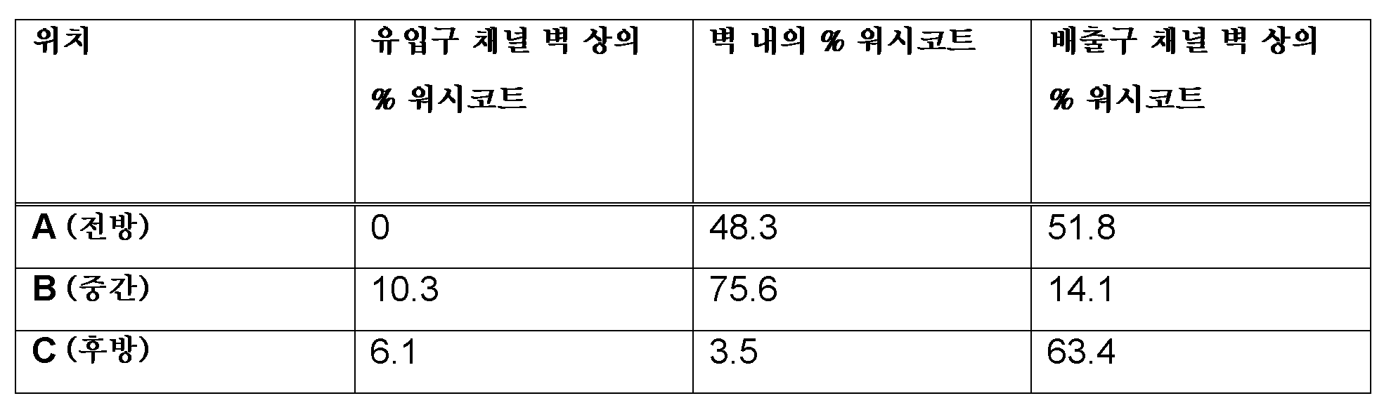
참조Reference
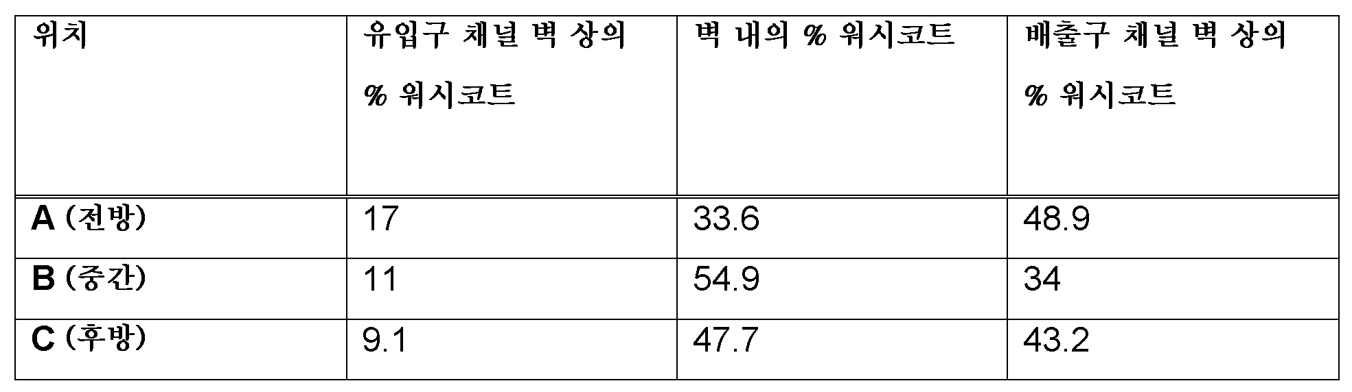
참조 샘플(비교예)은 실시예 4에 나타낸 더 현저한 웨지 형상이기 보다는 (축) 길이 (즉, 길이방향)의 부분을 따라 더 균질한 분포의 워시코트를 갖는 것으로 밝혀졌다.The reference sample (comparative example) was found to have a washcoat with a more homogeneous distribution along the (axial) length (i.e., longitudinal direction) portion rather than the more prominent wedge shape shown in Example 4. [
실시예 6Example 6
코팅 및 시효처리된 필터 실시예 4 및 그 참조물(비교예)의 저온 유동 배압 분석을 http://www.superflow.com/Flowbenches/sf1020.php에서 상업적으로 이용 가능한 슈퍼플로우 SF1020 장치를 사용하여 실시하였다.Coated and Aged Filters The cold flow back pressure analysis of Example 4 and its reference (comparative) was performed using a commercially available superflow SF1020 device at http://www.superflow.com/Flowbenches/sf1020.php Respectively.
21℃ 주위 온도 및 700 m3/hr의 유량에서, 결과는 다음과 같다:At an ambient temperature of 21 캜 and a flow rate of 700 m 3 / hr, the results are as follows:
실시예 4 = 92.82 mbar @ 700 m3/hr(9.28 KPa); 및Example 4 = 92.82 mbar @ 700 m 3 / hr (9.28 KPa); And
실시예 4 참조물 (비교예) = 116.56 mbar @ 700 m3/hr(11.66 KPa).Example 4 Reference (comparative) = 116.56 mbar @ 700 m 3 / hr (11.66 KPa).
이들 데이터로부터, 워시코트 성분의 D90을 조절함으로써, 본 발명에 따른 촉매 벽-유동형 필터는 종래 가솔린 미립자 필터에 비해 더 낮은 배압의 이점을 부가적으로 제공함을 알 수 있다.From these data, it can be seen that by adjusting the D90 of the washcoat component, the catalyst wall-flow filter according to the invention additionally provides the advantage of a lower backpressure compared to the conventional gasoline particulate filter.
본 발명의 바람직한 실시양태를 본원에 상세히 기재하였지만, 관련 기술분야의 통상의 기술자라면 첨부된 특허청구범위 또는 발명의 범주로부터 벗어나지 않고 그에 대한 변형이 이루어질 수 있음을 이해할 것이다.While preferred embodiments of the present invention have been described in detail herein, those skilled in the art will appreciate that variations can be made therein without departing from the scope of the appended claims or the invention.
불확실함을 피하기 위해, 본원에 인용된 모든 문헌의 전체 내용은 본원에 참조로 포함된다.To avoid uncertainty, the entire contents of all documents cited herein are incorporated herein by reference.
Claims (19)
(i) 알루미나;
(ii) 하나 이상의 백금족 금속; 및
(iii) 산소 저장 성분(OSC)을 포함하고,
OSC는 세리아, 또는 세륨을 포함하는 하나 이상의 혼합 산화물을 포함하고, 65:35 내지 85:15의 OSC 대 알루미나의 중량비로 존재하는, 촉매 벽-유동형 모노리스.Wherein the monolith comprises a porous substrate and a three-way catalyst (TWC), wherein the TWC is substantially distributed throughout the porous substrate, and wherein the TWC is a catalytic wall-flow monolith for use in an effluent treatment system,
(i) alumina;
(ii) one or more platinum group metals; And
(iii) an oxygen storage component (OSC)
The OSC comprises at least one mixed oxide comprising ceria, or cerium, and is present in a weight ratio of OSC to alumina of 65:35 to 85:15.
OSC가 세리아를 포함하는, 촉매 벽-유동형 모노리스.The method according to claim 1,
A catalyst wall-flowable monolith, wherein the OSC comprises ceria.
OSC가 세륨 및 지르코늄의 혼합 산화물; 세륨, 지르코늄 및 네오디뮴의 혼합 산화물; 프라세오디뮴 및 지르코늄의 혼합 산화물; 세륨, 지르코늄 및 프라세오디뮴의 혼합 산화물; 또는 프라세오디뮴, 세륨, 란타넘, 이트륨, 지르코늄 및 네오디뮴의 혼합 산화물을 포함하는, 촉매 벽-유동형 모노리스.3. The method of claim 2,
Mixed oxides of cerium and zirconium OSC; Mixed oxides of cerium, zirconium and neodymium; Mixed oxides of praseodymium and zirconium; Mixed oxides of cerium, zirconium and praseodymium; Or a mixed oxide of praseodymium, cerium, lanthanum, yttrium, zirconium and neodymium.
OSC가 프라세오디뮴을 포함하고 2 내지 10 중량%로 존재하는, 촉매 벽-유동형 모노리스.The method of claim 3,
A catalyst wall-flowable monolith wherein the OSC comprises praseodymium and is present from 2 to 10 wt%.
OSC가 프라세오디뮴을 포함하고, 제1의 복수의 채널은, 프라세오디뮴을 포함하는 OSC를 포함하는 벽상 TWC 코팅을 포함하는, 촉매 벽-유동형 모노리스.The method according to claim 3 or 4,
A catalyst wall-flowable monolith wherein the OSC comprises praseodymium and the first plurality of channels comprises a walled TWC coating comprising an OSC comprising praseodymium.
OSC 대 알루미나의 중량비가 약 75:25인, 촉매 벽-유동형 모노리스.6. The method according to any one of claims 1 to 5,
A catalyst wall-flowable monolith having a weight ratio of OSC to alumina of about 75:25.
하나 이상의 백금족 금속이 Pt, Pd 및 Rh, 또는 그 둘 이상의 조합으로부터 선택되는, 촉매 벽-유동형 모노리스.7. The method according to any one of claims 1 to 6,
Wherein the at least one platinum group metal is selected from Pt, Pd and Rh, or a combination of two or more thereof.
TWC가 다공성 기재 전반을 통해서 균질한, 촉매 벽-유동형 모노리스.8. The method according to any one of claims 1 to 7,
A catalyst wall-flow type monolith, wherein the TWC is homogeneous throughout the porous substrate.
모노리스는, 길이방향을 사이에 규정하는, 제1 면 및 제2 면을 가지고, 제1 및 제2의 복수의 채널이 길이방향으로 연장되며,
제1의 복수의 채널은 제1 면에서 개방되고 제2 면에서 폐쇄되며, 제2의 복수의 채널은 제2 면에서 개방되고 제1 면에서 폐쇄되며, 그리고
TWC는 제1 및 제2의 복수의 채널 중 적어도 하나의 표면 상에서 코팅으로서 더 존재하는, 촉매 벽-유동형 모노리스.9. The method according to any one of claims 1 to 8,
The monolith has a first surface and a second surface defining a longitudinal direction therebetween, the first and second plurality of channels extending in the longitudinal direction,
The first plurality of channels is opened on the first side and closed on the second side and the second plurality of channels is open on the second side and closed on the first side,
Wherein the TWC is further present as a coating on at least one surface of the first and second plurality of channels.
인접 채널들 사이의 기재의 평균 최소 두께가 8 내지 20 mil(0.02 내지 0.05 cm)인, 촉매 벽-유동형 모노리스.10. The method of claim 9,
A catalyst wall-flowable monolith having an average minimum thickness of the substrate between adjacent channels of between 8 and 20 mils (0.02 to 0.05 cm).
(a) 제1의 복수의 채널의 채널 벽 표면 상에 존재하는 벽상 코팅의 단위 부피당 하나 이상의 백금족 금속의 중량의 양이 길이방향을 따라 연속적으로 변화되고; 및/또는 (b) 제1의 복수의 채널의 채널 벽 표면 상에 존재하는 벽상 코팅 - 또는 실질적으로 벽상 코팅 - 의 층 두께는 길이방향을 따라 연속적으로 변화되는, 촉매 벽-유동형 모노리스.11. The method according to claim 9 or 10,
(a) the amount of weight of the at least one platinum group metal per unit volume of the wall coating present on the channel wall surface of the first plurality of channels is continuously varied along the length; And / or (b) the layer thickness of the wall coating or substantially the wall coating present on the channel wall surface of the first plurality of channels is continuously varied along the length direction.
길이방향을 사이에서 규정하는 제1 면 및 제2 면, 그리고 길이방향으로 연장되는 제1 및 제2의 복수의 채널을 갖는 다공성 기재를 제공하는 단계로서, 여기서 제1의 복수 채널은 제1 면에서 개방되어 있고 제2 면에서 폐쇄되어 있으며, 제2의 복수 채널은 제2 면에서 개방되어 있고 제1 면에서 폐쇄되어 있는, 단계;
다공성 기재를, 촉매 재료를 포함하는 워시코트로 침윤시키는 단계; 및
다공성 기재 내의 촉매 재료를 하소시키는 단계를 포함하고,
촉매 재료는:
(i) 알루미나;
(ii) 하나 이상의 백금족 금속; 및
(iii) 산소 저장 성분(OSC)을 포함하고,
OSC는 세리아, 또는 세륨을 포함하는 하나 이상의 혼합 산화물을 포함하고, 65:35 내지 85:15의 OSC 대 알루미나의 중량비로 존재하는, 방법.A method of manufacturing a catalyst wall-flow type monolith comprising:
Providing a porous substrate having a first side and a second side defining a longitudinal direction therebetween, and a first and a second plurality of channels extending in a longitudinal direction, wherein the first plurality of channels comprises a first side And the second plurality of channels are open on the second surface and closed on the first surface;
Infiltrating the porous substrate with a washcoat comprising a catalytic material; And
And calcining the catalyst material in the porous substrate,
The catalyst material is:
(i) alumina;
(ii) one or more platinum group metals; And
(iii) an oxygen storage component (OSC)
Wherein the OSC comprises at least one mixed oxide comprising ceria or cerium and is present in a weight ratio of OSC to alumina of 65:35 to 85:15.
다공성 기재를 침윤시키는 단계 전의 워시코트의 준비는:
Pt 및/또는 Pd를 알루미나와 혼합하고 하소시켜, 촉매 재료의 제1 부분을 형성하는 것을 포함하는, 방법.16. The method of claim 15,
The preparation of the washcoat prior to the step of infiltrating the porous substrate comprises:
Mixing Pt and / or Pd with alumina and calcining to form a first portion of the catalyst material.
다공성 기재를 침윤시키는 단계 전의 워시코트의 준비는:
Rh와 OSC를 혼합하고 하소시켜, 촉매 재료의 제2 부분을 형성하는, 방법.17. The method according to claim 15 or 16,
The preparation of the washcoat prior to the step of infiltrating the porous substrate comprises:
Rh and OSC are mixed and calcined to form a second portion of catalyst material.
촉매 벽-유동형 모노리스가 제1항 내지 제11항 중 어느 한 항에 따른 모노리스인, 방법.18. The method according to any one of claims 15 to 17,
Wherein the catalyst wall-flowable monolith is a monolith according to any one of claims 1 to 11.
A method for treating a combustion exhaust gas from a positive ignition internal combustion engine containing nitrogen oxide (NOx), carbon monoxide (CO), unburned hydrocarbon fuel (HC) and particulate matter (PM) Comprising contacting a catalyst wall-flow type filter according to any one of claims 1 to 11.
Applications Claiming Priority (5)
| Application Number | Priority Date | Filing Date | Title |
|---|---|---|---|
| GB1522917.2A GB2545747A (en) | 2015-12-24 | 2015-12-24 | Gasoline particulate filter |
| GB1522917.2 | 2015-12-24 | ||
| GB1604915.7 | 2016-03-23 | ||
| GBGB1604915.7A GB201604915D0 (en) | 2015-12-24 | 2016-03-23 | Gasoline particulate filter |
| PCT/GB2016/054070 WO2017109514A1 (en) | 2015-12-24 | 2016-12-23 | Gasoline particulate filter |
Publications (2)
| Publication Number | Publication Date |
|---|---|
| KR20180098600A true KR20180098600A (en) | 2018-09-04 |
| KR102694306B1 KR102694306B1 (en) | 2024-08-13 |
Family
ID=55359052
Family Applications (1)
| Application Number | Title | Priority Date | Filing Date |
|---|---|---|---|
| KR1020187021204A Active KR102694306B1 (en) | 2015-12-24 | 2016-12-23 | gasoline particulate filter |
Country Status (10)
| Country | Link |
|---|---|
| US (1) | US10625243B2 (en) |
| EP (1) | EP3393654B1 (en) |
| JP (1) | JP6920304B2 (en) |
| KR (1) | KR102694306B1 (en) |
| CN (1) | CN108602050B (en) |
| BR (1) | BR112018012782B1 (en) |
| DE (1) | DE112016005997T5 (en) |
| GB (3) | GB2545747A (en) |
| RU (1) | RU2732400C2 (en) |
| WO (1) | WO2017109514A1 (en) |
Cited By (2)
| Publication number | Priority date | Publication date | Assignee | Title |
|---|---|---|---|---|
| KR20200124270A (en) * | 2018-02-26 | 2020-11-02 | 바스프 코포레이션 | Gasoline engine exhaust gas post-treatment catalyst |
| KR20230079369A (en) * | 2020-09-29 | 2023-06-07 | 존슨 맛쎄이 퍼블릭 리미티드 컴파니 | Catalyst articles for filtering fine particles and uses thereof |
Families Citing this family (42)
| Publication number | Priority date | Publication date | Assignee | Title |
|---|---|---|---|---|
| MY180110A (en) * | 2014-12-12 | 2020-11-23 | Honda Motor Co Ltd | Exhaust gas purifying catalyst |
| US20180071679A1 (en) * | 2015-03-19 | 2018-03-15 | Basf Corporation | Automotive Catalysts With Palladium Supported In An Alumina-Free Layer |
| CN108367224B (en) | 2015-12-09 | 2022-04-29 | 康宁股份有限公司 | Porous ceramic materials, filters and articles |
| DE102017116405A1 (en) | 2017-07-20 | 2017-10-26 | FEV Europe GmbH | Method for determining the loading of a particulate filter with ash |
| JP7472014B2 (en) * | 2017-07-27 | 2024-04-22 | ビーエーエスエフ コーポレーション | N2O removal from automotive exhaust for lean/rich systems |
| EP3505246B1 (en) | 2017-12-19 | 2019-10-23 | Umicore Ag & Co. Kg | Catalytically active particle filter |
| EP3505245B1 (en) | 2017-12-19 | 2019-10-23 | Umicore Ag & Co. Kg | Catalytically active particle filter |
| EP3501648B1 (en) * | 2017-12-19 | 2023-10-04 | Umicore Ag & Co. Kg | Catalytically active particle filter |
| JP6544880B1 (en) * | 2017-12-28 | 2019-07-17 | ユミコア日本触媒株式会社 | Catalyst for hydrogen production and catalyst for purification of exhaust gas using the same |
| EP3749438A1 (en) | 2018-02-05 | 2020-12-16 | BASF Corporation | Four-way conversion catalyst having improved filter properties |
| JP6771119B2 (en) * | 2018-03-30 | 2020-10-21 | 三井金属鉱業株式会社 | Exhaust gas purification catalyst |
| JP7065551B2 (en) * | 2018-08-09 | 2022-05-12 | エヌ・イーケムキャット株式会社 | Catalyst coated gasoline particulate filter and its manufacturing method |
| EP3843883A1 (en) * | 2018-08-31 | 2021-07-07 | BASF Corporation | Four-way conversion catalyst for the treatment of an exhaust gas stream |
| JP7171751B2 (en) * | 2018-09-28 | 2022-11-15 | ユミコア日本触媒株式会社 | Exhaust gas purifying catalyst, method for purifying exhaust gas, and method for manufacturing exhaust gas purifying catalyst |
| EP3639919B1 (en) | 2018-10-18 | 2025-07-09 | Umicore AG & Co. KG | Exhaust gas purification system for a gasoline engine |
| DE102018127955A1 (en) * | 2018-11-08 | 2020-05-14 | Umicore Ag & Co. Kg | Catalytically active particle filter with high filtration efficiency |
| JP6740506B1 (en) * | 2018-12-27 | 2020-08-12 | ユミコア日本触媒株式会社 | Exhaust gas purification catalyst and exhaust gas purification method |
| KR20210111251A (en) | 2019-01-04 | 2021-09-10 | 패서픽 인더스트리얼 디벨럽먼트 코퍼레이션 | Nanocrystal sized cerium-zirconium oxide material and method for preparing same |
| CN109621952B (en) * | 2019-02-11 | 2021-09-03 | 无锡威孚环保催化剂有限公司 | Catalyst for gasoline engine tail gas particulate matter filter and preparation method thereof |
| WO2020200398A1 (en) | 2019-03-29 | 2020-10-08 | Umicore Ag & Co. Kg | Catalytically active particulate filter |
| GB2583581B (en) * | 2019-03-29 | 2022-06-15 | Johnson Matthey Plc | A catalyst article and the use thereof for filtering fine particles |
| US12264608B2 (en) * | 2019-04-22 | 2025-04-01 | Basf Mobile Emissions Catalysts Llc | Catalyzed gasoline particulate filter |
| EP3733266B1 (en) * | 2019-05-03 | 2024-04-24 | Johnson Matthey Public Limited Company | Catalyst article, method and use |
| WO2021012107A1 (en) | 2019-07-19 | 2021-01-28 | Rhodia Operations | Mixed oxide based on cerium and zirconium |
| JP7386651B2 (en) * | 2019-09-02 | 2023-11-27 | 株式会社キャタラー | Exhaust gas purification catalyst |
| JP6921261B1 (en) * | 2020-03-26 | 2021-08-18 | 株式会社キャタラー | Exhaust gas purification catalyst device |
| US11618008B2 (en) * | 2020-10-05 | 2023-04-04 | Ford Global Technologies, Llc | Precious group metal on pyrochlore-phase ceria zirconia with superior oxygen storage capacity and TWC performance |
| US11788450B2 (en) * | 2020-10-30 | 2023-10-17 | Johnson Matthey Public Limited Company | TWC catalysts for gasoline engine exhaust gas treatments |
| EP4015065B1 (en) * | 2020-12-15 | 2025-02-26 | Umicore AG & Co. KG | Catalytically active particle filter with high filtration efficiency |
| CN118647454A (en) | 2022-01-25 | 2024-09-13 | 庄信万丰(上海)化工有限公司 | Method for producing a gasoline particulate filter |
| US11801491B1 (en) * | 2022-04-21 | 2023-10-31 | GM Global Technology Operations LLC | Three-way catalyst with reduced palladium loading and method of making the three-way catalyst |
| US12544739B2 (en) | 2022-05-27 | 2026-02-10 | Johnson Matthey Public Limited Company | Method for manufacturing gasoline particulate filter |
| CN120019031A (en) | 2022-08-12 | 2025-05-16 | 罗地亚经营管理公司 | Cerium-based and zirconium-based mixed oxides |
| JP2025531218A (en) * | 2022-09-27 | 2025-09-19 | ビーエーエスエフ モバイル エミッションズ カタリスツ エルエルシー | Catalyzed Particulate Filter |
| JP2025531356A (en) * | 2022-09-27 | 2025-09-19 | ビーエーエスエフ モバイル エミッションズ カタリスツ エルエルシー | Catalyzed Particulate Filter |
| EP4420764B1 (en) | 2023-02-23 | 2025-07-30 | Johnson Matthey Public Limited Company | Catalytic wall flow filter |
| EP4438161A1 (en) | 2023-03-28 | 2024-10-02 | Johnson Matthey Public Limited Company | Catalytic gasoline particulate filter |
| US20240399309A1 (en) | 2023-05-31 | 2024-12-05 | Johnson Matthey Public Limited Company | Catalytic wall flow filter |
| WO2025199853A1 (en) | 2024-03-28 | 2025-10-02 | Johnson Matthey Public Limited Company | Catalytic wall flow filter |
| EP4640303A1 (en) | 2024-04-25 | 2025-10-29 | Johnson Matthey Public Limited Company | Catalytic gasoline particulate filter |
| EP4717346A1 (en) | 2024-09-26 | 2026-04-01 | Johnson Matthey Public Limited Company | Method for the manufacture of a catalytic gasoline particulate filter |
| EP4729155A1 (en) | 2024-10-15 | 2026-04-22 | Johnson Matthey Public Limited Company | Catalytic gasoline particulate filter |
Citations (9)
| Publication number | Priority date | Publication date | Assignee | Title |
|---|---|---|---|---|
| KR20100125291A (en) * | 2008-02-05 | 2010-11-30 | 바스프 코포레이션 | Gasoline engine emissions treatment systems having particulate traps |
| JP2011212639A (en) * | 2010-04-02 | 2011-10-27 | Toyota Motor Corp | Catalyst for vehicle exhaust gas purification |
| JP5176727B2 (en) * | 2008-07-02 | 2013-04-03 | マツダ株式会社 | Exhaust gas purification catalyst material manufacturing method and exhaust gas purification catalyst |
| KR20130092413A (en) * | 2010-04-19 | 2013-08-20 | 바스프 코포레이션 | Gasoline engine emissions treatment systems having gasoline particulate filters |
| US20140205523A1 (en) * | 2013-01-24 | 2014-07-24 | Basf Se | Automotive Catalyst Composites Having A Two-Metal Layer |
| WO2014162140A1 (en) * | 2013-04-05 | 2014-10-09 | Johnson Matthey Public Limited Company | Filter substrate comprising three-way catalyst |
| WO2015079908A1 (en) * | 2013-11-28 | 2015-06-04 | 株式会社キャタラー | Exhaust gas purification catalyst |
| KR20150119140A (en) * | 2013-02-15 | 2015-10-23 | 존슨 맛쎄이 퍼블릭 리미티드 컴파니 | Positive ignition engine and exhaust system comprising three-way catalysed filter |
| JP5859487B2 (en) * | 2012-06-20 | 2016-02-10 | 株式会社豊田中央研究所 | Exhaust gas purification catalyst carrier, exhaust gas purification catalyst using the same, and method for producing exhaust gas purification catalyst carrier |
Family Cites Families (26)
| Publication number | Priority date | Publication date | Assignee | Title |
|---|---|---|---|---|
| JPS60168537A (en) * | 1984-02-10 | 1985-09-02 | Nippon Shokubai Kagaku Kogyo Co Ltd | Preparation of integral structure type catalyst for purifying exhaust gas |
| US5041407A (en) * | 1989-12-14 | 1991-08-20 | Allied-Signal Inc. | High-temperature three-way catalyst for treating automotive exhaust gases |
| CA2097609C (en) | 1991-10-03 | 1999-03-16 | Shinichi Takeshima | Device for purifying exhaust of internal combustion engine |
| CA2144627A1 (en) * | 1992-09-28 | 1994-04-14 | Jack Curtis Ii Summers | Palladium-containing three-way automotive catalysts having unique support |
| DE19714707A1 (en) * | 1997-04-09 | 1998-10-15 | Degussa | Oxygen-storing material with high temperature stability and process for its production |
| GB9805815D0 (en) | 1998-03-19 | 1998-05-13 | Johnson Matthey Plc | Manufacturing process |
| IT1319258B1 (en) * | 2000-10-31 | 2003-09-26 | Sued Chemie Mt Srl | CATALYST FOR THE HYDRODECLORURATION OF CARBON TETRACHLORIDE ACLOROFORM. |
| JP4019357B2 (en) * | 2002-05-02 | 2007-12-12 | 日産自動車株式会社 | Method for producing exhaust gas purification catalyst powder and method for producing exhaust gas purification catalyst |
| DE10247946A1 (en) * | 2002-10-15 | 2004-04-29 | Robert Bosch Gmbh | exhaust aftertreatment arrangement |
| JP2007275704A (en) * | 2006-04-03 | 2007-10-25 | Johnson Matthey Japan Inc | Exhaust gas catalyst and exhaust gas treating device using the same |
| JP4316586B2 (en) * | 2006-05-26 | 2009-08-19 | 三井金属鉱業株式会社 | Exhaust gas purification catalyst |
| DE102007046158B4 (en) | 2007-09-27 | 2014-02-13 | Umicore Ag & Co. Kg | Use of a catalytically active particulate filter for the removal of particles from the exhaust gas of combustion engines operated with predominantly stoichiometric air / fuel mixture |
| DE502007002874D1 (en) | 2007-09-28 | 2010-04-01 | Umicore Ag & Co Kg | Removal of particles from the exhaust gas of combustion engines operated with predominantly stoichiometric air / fuel mixture |
| FR2947735B1 (en) * | 2009-07-09 | 2011-08-12 | Saint Gobain Ct Recherches | HONEYCOMB STRUCTURE MARQUEE |
| GB201000019D0 (en) | 2010-01-04 | 2010-02-17 | Johnson Matthey Plc | Coating a monolith substrate with catalyst component |
| RU2570454C2 (en) * | 2010-02-01 | 2015-12-10 | Джонсон Мэтти Плс | Extruded scr-filter |
| US20110212639A1 (en) | 2010-02-26 | 2011-09-01 | Jeffrey Paquette | Circuit card assembly connector and interconnection system |
| JP5938819B2 (en) * | 2011-10-06 | 2016-06-22 | ジョンソン、マッセイ、パブリック、リミテッド、カンパニーJohnson Matthey Public Limited Company | Oxidation catalyst for exhaust gas treatment |
| GB201207313D0 (en) * | 2012-04-24 | 2012-06-13 | Johnson Matthey Plc | Filter substrate comprising three-way catalyst |
| US20130336864A1 (en) * | 2012-06-15 | 2013-12-19 | Basf Corporation | Composites Of Mixed Metal Oxides For Oxygen Storage |
| GB201311615D0 (en) | 2013-06-03 | 2013-08-14 | Johnson Matthey Plc | Method of coating a substrate with a catalyst component |
| US20140369912A1 (en) * | 2013-06-13 | 2014-12-18 | Basf Corporation | Integrated Supports for Emission Control Catalysts |
| GB201405277D0 (en) | 2014-03-25 | 2014-05-07 | Johnson Matthey Plc | Method for coating a filter substrate |
| US9707545B2 (en) * | 2015-02-05 | 2017-07-18 | Johnson Matthey Public Limited Company | Three-way catalyst |
| EP3281697A4 (en) * | 2015-04-07 | 2018-03-21 | Umicore Shokubai Japan Co., Ltd. | Purification catalyst for internal combustion engine exhaust gases and exhaust gas purification method using said catalyst |
| EP3881932A1 (en) * | 2015-06-29 | 2021-09-22 | Corning Incorporated | Porous ceramic body to reduce emissions |
-
2015
- 2015-12-24 GB GB1522917.2A patent/GB2545747A/en not_active Withdrawn
-
2016
- 2016-03-23 GB GBGB1604915.7A patent/GB201604915D0/en not_active Ceased
- 2016-12-23 EP EP16822505.0A patent/EP3393654B1/en active Active
- 2016-12-23 US US16/065,439 patent/US10625243B2/en active Active
- 2016-12-23 WO PCT/GB2016/054070 patent/WO2017109514A1/en not_active Ceased
- 2016-12-23 BR BR112018012782-5A patent/BR112018012782B1/en active IP Right Grant
- 2016-12-23 CN CN201680080634.XA patent/CN108602050B/en active Active
- 2016-12-23 RU RU2018126874A patent/RU2732400C2/en active
- 2016-12-23 DE DE112016005997.3T patent/DE112016005997T5/en not_active Ceased
- 2016-12-23 GB GB1707959.1A patent/GB2558332B/en active Active
- 2016-12-23 JP JP2018533092A patent/JP6920304B2/en active Active
- 2016-12-23 KR KR1020187021204A patent/KR102694306B1/en active Active
Patent Citations (9)
| Publication number | Priority date | Publication date | Assignee | Title |
|---|---|---|---|---|
| KR20100125291A (en) * | 2008-02-05 | 2010-11-30 | 바스프 코포레이션 | Gasoline engine emissions treatment systems having particulate traps |
| JP5176727B2 (en) * | 2008-07-02 | 2013-04-03 | マツダ株式会社 | Exhaust gas purification catalyst material manufacturing method and exhaust gas purification catalyst |
| JP2011212639A (en) * | 2010-04-02 | 2011-10-27 | Toyota Motor Corp | Catalyst for vehicle exhaust gas purification |
| KR20130092413A (en) * | 2010-04-19 | 2013-08-20 | 바스프 코포레이션 | Gasoline engine emissions treatment systems having gasoline particulate filters |
| JP5859487B2 (en) * | 2012-06-20 | 2016-02-10 | 株式会社豊田中央研究所 | Exhaust gas purification catalyst carrier, exhaust gas purification catalyst using the same, and method for producing exhaust gas purification catalyst carrier |
| US20140205523A1 (en) * | 2013-01-24 | 2014-07-24 | Basf Se | Automotive Catalyst Composites Having A Two-Metal Layer |
| KR20150119140A (en) * | 2013-02-15 | 2015-10-23 | 존슨 맛쎄이 퍼블릭 리미티드 컴파니 | Positive ignition engine and exhaust system comprising three-way catalysed filter |
| WO2014162140A1 (en) * | 2013-04-05 | 2014-10-09 | Johnson Matthey Public Limited Company | Filter substrate comprising three-way catalyst |
| WO2015079908A1 (en) * | 2013-11-28 | 2015-06-04 | 株式会社キャタラー | Exhaust gas purification catalyst |
Cited By (2)
| Publication number | Priority date | Publication date | Assignee | Title |
|---|---|---|---|---|
| KR20200124270A (en) * | 2018-02-26 | 2020-11-02 | 바스프 코포레이션 | Gasoline engine exhaust gas post-treatment catalyst |
| KR20230079369A (en) * | 2020-09-29 | 2023-06-07 | 존슨 맛쎄이 퍼블릭 리미티드 컴파니 | Catalyst articles for filtering fine particles and uses thereof |
Also Published As
| Publication number | Publication date |
|---|---|
| KR102694306B1 (en) | 2024-08-13 |
| GB201707959D0 (en) | 2017-07-05 |
| DE112016005997T5 (en) | 2018-08-30 |
| BR112018012782B1 (en) | 2021-10-26 |
| US10625243B2 (en) | 2020-04-21 |
| RU2018126874A (en) | 2020-01-24 |
| EP3393654B1 (en) | 2020-08-12 |
| JP2019509166A (en) | 2019-04-04 |
| GB201522917D0 (en) | 2016-02-10 |
| EP3393654A1 (en) | 2018-10-31 |
| US20190009254A1 (en) | 2019-01-10 |
| GB2558332B (en) | 2020-10-28 |
| GB201604915D0 (en) | 2016-05-04 |
| GB2545747A (en) | 2017-06-28 |
| CN108602050B (en) | 2021-09-21 |
| RU2732400C2 (en) | 2020-09-16 |
| CN108602050A (en) | 2018-09-28 |
| BR112018012782A2 (en) | 2018-12-04 |
| RU2018126874A3 (en) | 2020-04-16 |
| WO2017109514A1 (en) | 2017-06-29 |
| JP6920304B2 (en) | 2021-08-18 |
| GB2558332A (en) | 2018-07-11 |
Similar Documents
| Publication | Publication Date | Title |
|---|---|---|
| KR102694306B1 (en) | gasoline particulate filter | |
| JP6970662B2 (en) | Gasoline particulate filter | |
| CN104254387B (en) | Filter substrates containing three-way catalysts | |
| JP6687666B2 (en) | Exhaust system for vehicle positive ignition internal combustion engine | |
| RU2668191C2 (en) | Positive ignition engine and exhaust system comprising catalysed zone-coated filter substrate | |
| RU2504431C2 (en) | NOx RETAINING MATERIALS AND TRAPS RESISTANT TO THERMAL AGEING | |
| KR102102695B1 (en) | Positive ignition engine and exhaust system comprising three-way catalysed filter | |
| RU2641814C2 (en) | Catalytic particle filter | |
| KR101975627B1 (en) | Diesel oxidation catalysts, systems and methods of treatment | |
| KR20150140727A (en) | Filter substrate comprising three-way catalyst | |
| KR102890659B1 (en) | Catalytic article for filtering fine particles and use thereof |
Legal Events
| Date | Code | Title | Description |
|---|---|---|---|
| PA0105 | International application |
Patent event date: 20180723 Patent event code: PA01051R01D Comment text: International Patent Application |
|
| PG1501 | Laying open of application | ||
| A201 | Request for examination | ||
| PA0201 | Request for examination |
Patent event code: PA02012R01D Patent event date: 20211221 Comment text: Request for Examination of Application |
|
| E902 | Notification of reason for refusal | ||
| PE0902 | Notice of grounds for rejection |
Comment text: Notification of reason for refusal Patent event date: 20231031 Patent event code: PE09021S01D |
|
| E701 | Decision to grant or registration of patent right | ||
| PE0701 | Decision of registration |
Patent event code: PE07011S01D Comment text: Decision to Grant Registration Patent event date: 20240730 |
|
| GRNT | Written decision to grant | ||
| PR0701 | Registration of establishment |
Comment text: Registration of Establishment Patent event date: 20240807 Patent event code: PR07011E01D |
|
| PR1002 | Payment of registration fee |
Payment date: 20240808 End annual number: 3 Start annual number: 1 |
|
| PG1601 | Publication of registration |