KR20180098590A - Photoconversion module - Google Patents
Photoconversion module Download PDFInfo
- Publication number
- KR20180098590A KR20180098590A KR1020187020989A KR20187020989A KR20180098590A KR 20180098590 A KR20180098590 A KR 20180098590A KR 1020187020989 A KR1020187020989 A KR 1020187020989A KR 20187020989 A KR20187020989 A KR 20187020989A KR 20180098590 A KR20180098590 A KR 20180098590A
- Authority
- KR
- South Korea
- Prior art keywords
- substrate
- light
- layer
- laser
- laser light
- Prior art date
- Legal status (The legal status is an assumption and is not a legal conclusion. Google has not performed a legal analysis and makes no representation as to the accuracy of the status listed.)
- Granted
Links
Images


Classifications
-
- F—MECHANICAL ENGINEERING; LIGHTING; HEATING; WEAPONS; BLASTING
- F21—LIGHTING
- F21S—NON-PORTABLE LIGHTING DEVICES; SYSTEMS THEREOF; VEHICLE LIGHTING DEVICES SPECIALLY ADAPTED FOR VEHICLE EXTERIORS
- F21S41/00—Illuminating devices specially adapted for vehicle exteriors, e.g. headlamps
- F21S41/10—Illuminating devices specially adapted for vehicle exteriors, e.g. headlamps characterised by the light source
- F21S41/14—Illuminating devices specially adapted for vehicle exteriors, e.g. headlamps characterised by the light source characterised by the type of light source
- F21S41/16—Laser light sources
-
- F—MECHANICAL ENGINEERING; LIGHTING; HEATING; WEAPONS; BLASTING
- F21—LIGHTING
- F21K—NON-ELECTRIC LIGHT SOURCES USING LUMINESCENCE; LIGHT SOURCES USING ELECTROCHEMILUMINESCENCE; LIGHT SOURCES USING CHARGES OF COMBUSTIBLE MATERIAL; LIGHT SOURCES USING SEMICONDUCTOR DEVICES AS LIGHT-GENERATING ELEMENTS; LIGHT SOURCES NOT OTHERWISE PROVIDED FOR
- F21K9/00—Light sources using semiconductor devices as light-generating elements, e.g. using light-emitting diodes [LED] or lasers
- F21K9/60—Optical arrangements integrated in the light source, e.g. for improving the colour rendering index or the light extraction
- F21K9/64—Optical arrangements integrated in the light source, e.g. for improving the colour rendering index or the light extraction using wavelength conversion means distinct or spaced from the light-generating element, e.g. a remote phosphor layer
-
- F—MECHANICAL ENGINEERING; LIGHTING; HEATING; WEAPONS; BLASTING
- F21—LIGHTING
- F21S—NON-PORTABLE LIGHTING DEVICES; SYSTEMS THEREOF; VEHICLE LIGHTING DEVICES SPECIALLY ADAPTED FOR VEHICLE EXTERIORS
- F21S41/00—Illuminating devices specially adapted for vehicle exteriors, e.g. headlamps
- F21S41/10—Illuminating devices specially adapted for vehicle exteriors, e.g. headlamps characterised by the light source
- F21S41/14—Illuminating devices specially adapted for vehicle exteriors, e.g. headlamps characterised by the light source characterised by the type of light source
- F21S41/176—Light sources where the light is generated by photoluminescent material spaced from a primary light generating element
-
- F—MECHANICAL ENGINEERING; LIGHTING; HEATING; WEAPONS; BLASTING
- F21—LIGHTING
- F21S—NON-PORTABLE LIGHTING DEVICES; SYSTEMS THEREOF; VEHICLE LIGHTING DEVICES SPECIALLY ADAPTED FOR VEHICLE EXTERIORS
- F21S41/00—Illuminating devices specially adapted for vehicle exteriors, e.g. headlamps
- F21S41/40—Illuminating devices specially adapted for vehicle exteriors, e.g. headlamps characterised by screens, non-reflecting members, light-shielding members or fixed shades
-
- F—MECHANICAL ENGINEERING; LIGHTING; HEATING; WEAPONS; BLASTING
- F21—LIGHTING
- F21V—FUNCTIONAL FEATURES OR DETAILS OF LIGHTING DEVICES OR SYSTEMS THEREOF; STRUCTURAL COMBINATIONS OF LIGHTING DEVICES WITH OTHER ARTICLES, NOT OTHERWISE PROVIDED FOR
- F21V9/00—Elements for modifying spectral properties, polarisation or intensity of the light emitted, e.g. filters
- F21V9/30—Elements containing photoluminescent material distinct from or spaced from the light source
-
- H01L33/50—
-
- H—ELECTRICITY
- H10—SEMICONDUCTOR DEVICES; ELECTRIC SOLID-STATE DEVICES NOT OTHERWISE PROVIDED FOR
- H10H—INORGANIC LIGHT-EMITTING SEMICONDUCTOR DEVICES HAVING POTENTIAL BARRIERS
- H10H20/00—Individual inorganic light-emitting semiconductor devices having potential barriers, e.g. light-emitting diodes [LED]
- H10H20/80—Constructional details
- H10H20/85—Packages
- H10H20/851—Wavelength conversion means
-
- F—MECHANICAL ENGINEERING; LIGHTING; HEATING; WEAPONS; BLASTING
- F21—LIGHTING
- F21Y—INDEXING SCHEME ASSOCIATED WITH SUBCLASSES F21K, F21L, F21S and F21V, RELATING TO THE FORM OR THE KIND OF THE LIGHT SOURCES OR OF THE COLOUR OF THE LIGHT EMITTED
- F21Y2115/00—Light-generating elements of semiconductor light sources
- F21Y2115/30—Semiconductor lasers
-
- H—ELECTRICITY
- H10—SEMICONDUCTOR DEVICES; ELECTRIC SOLID-STATE DEVICES NOT OTHERWISE PROVIDED FOR
- H10H—INORGANIC LIGHT-EMITTING SEMICONDUCTOR DEVICES HAVING POTENTIAL BARRIERS
- H10H20/00—Individual inorganic light-emitting semiconductor devices having potential barriers, e.g. light-emitting diodes [LED]
- H10H20/80—Constructional details
- H10H20/85—Packages
- H10H20/851—Wavelength conversion means
- H10H20/8514—Wavelength conversion means characterised by their shape, e.g. plate or foil
Landscapes
- Engineering & Computer Science (AREA)
- General Engineering & Computer Science (AREA)
- Physics & Mathematics (AREA)
- Optics & Photonics (AREA)
- Spectroscopy & Molecular Physics (AREA)
- Microelectronics & Electronic Packaging (AREA)
- Semiconductor Lasers (AREA)
- Non-Portable Lighting Devices Or Systems Thereof (AREA)
- Optical Filters (AREA)
- Led Device Packages (AREA)
Abstract
본 발명은 투명 기판(120), 및 기판(120)의 광 출사면에 부착된 변환 층(110)을 포함하는 광 변환 모듈(100)에 관한 것으로, 광 입사면을 통해 기판(120)에 입사하는 제1 파장 범위의 레이저 광(10)의 일부를 제1 파장 범위와 다른 제2 파장 범위의 변환된 레이저 광(20)으로 변환하고, 레이저 광(10)의 다른 일부를 투과시켜, 투과된 레이저 광(15)과 변환된 레이저 광(20) 일부의 혼합물이, 변환 층(110)이 기판(120)의 광 출사면에 부착된 면에 반대되는 순방향으로 변환 층(110)을 떠나도록 변환 층(110)이 배열되고, 기판(120)의 광 입사면에서 전반사되는 기판에 입사하는 변환된 레이저 광(20)이 광 입사면에서의 1회의 전반사 이후 변환 층(110)에 충돌하지 않도록 광 출사면에 수직한 기판(120)의 두께를 정하여, 광 출사면을 통해 기판에 입사하는 변환된 레이저 광(20)이 변환 층(110)으로 재진입하는 것을 억제하도록 기판(120)이 배열된다. 본 발명은 또한 이러한 광 변환 모듈(100)을 포함하는 레이저-기반 광원(200), 특히 자동차 전조등을 더 설명한다. 본 발명은 또한 그러한 광 변환 모듈(100)을 제조하는 방법에 관한 것이다.The present invention relates to a light conversion module (100) comprising a transparent substrate (120) and a conversion layer (110) attached to the light exit surface of the substrate (120) Converts a part of the laser light 10 in the first wavelength range into the converted laser light 20 in the second wavelength range different from the first wavelength range and transmits the other part of the laser light 10, The mixture of the laser light 15 and a part of the converted laser light 20 is converted so that the conversion layer 110 leaves the conversion layer 110 in a direction opposite to the surface attached to the light output surface of the substrate 120 The layer 110 is arranged so that the converted laser light 20 incident on the substrate totally reflected on the light incident surface of the substrate 120 does not collide with the conversion layer 110 after total reflection once on the light incident surface, The thickness of the substrate 120 perpendicular to the emitting surface is determined and the converted laser light 20 incident on the substrate through the light emitting surface is converted The substrate 120 is arranged so as to inhibit re-entry into the layer 110. The present invention further describes a laser-based light source 200 that includes such a light conversion module 100, particularly a car headlight. The invention also relates to a method of manufacturing such a light conversion module (100).
Description
본 발명은 광 변환 모듈, 그러한 광 변환 모듈을 포함하는 레이저-기반 광원, 및 광 변환 모듈의 제조 방법에 관한 것이다.The present invention relates to a light conversion module, a laser-based light source including such a light conversion module, and a method of manufacturing the light conversion module.
최신의 자동차 전조등에서, 광 분포가 동적으로 바뀔 수 있는 적응형 시스템으로의 추세가 강력하다. 예를 들어, 눈부심을 방지하기 위해 다가오는 자동차에 할애할 수 있는 잘 정의되고 움직이는 어두운 섹션이 있는 하이 빔 패턴(high-beam pattern)을 갖고 싶을 수 있다. 또는 주어진 도로 표지판, 또는 예를 들어 자동차의 카메라가 감지할 수 있는 장애물을 조명하고 싶을 수 있다.In modern automotive headlights, the trend towards adaptive systems in which light distribution can be changed dynamically is strong. For example, you might want to have a high-beam pattern with a well-defined, moving dark section that can be dedicated to an oncoming car to avoid glare. Or you may want to illuminate a given road sign, or an obstacle that can be detected, for example, by a car's camera.
전형적으로, 이러한 시스템들은 전환 가능한 기계적 애퍼처들(apertures), LED 매트릭스 조명들, (빔머들(beamers)에서와 같은) 마이크로 디스플레이, 또는 레이저 스캐너와 같이, 성능 뿐만 아니라, 복잡성도 증가하는 다양한 접근 방식을 통해 실현될 수 있다. 레이저 스캐너의 원리는 소형 미러, 전형적으로는 마이크로 전자 기계 시스템(micro electromechanical system, MEMS)에 의해 전자적으로 스위칭되고 방향 제어될 수 있는 강한 청색 레이저 빔을 포함한다. 이러한 방식으로, 광 변환 모듈의 변환기 또는 인광체 표면을 통해 신속하게 조종되어(steered) 부분적으로 황색 광으로 변환되고, 그 황색 광이 나머지 청색 광과 합해져 백색광을 형성한다. 인광체 상의 백색 광 스폿의 움직임이 충분히 빠르면, 변동 없는 백색광 분포 또는 이미지로 인식된다. 이러한 이미지는 렌즈를 통해 도로에 투사된다. 레이저 빔의 적절한 스위칭(온 및 오프, 상이한 강도들)과 동기화된 미러 움직임의 적절한 제어에 의해, 인광체 상의 매우 다양한 이미지들, 및 그에 따른 - 도로상의 광 분포가 생성될 수 있다.Typically, such systems include a variety of approaches that increase complexity as well as performance, such as switchable mechanical apertures, LED matrix lights, microdisplays (such as in beamers), or laser scanners Method can be realized. The principle of laser scanners includes a strong blue laser beam that can be electronically switched and directionally controlled by a small mirror, typically a micro electromechanical system (MEMS). In this way, it is quickly steered through the transducer or phosphor surface of the light conversion module and is partially converted into yellow light, which is combined with the rest of the blue light to form white light. If the movement of the white light spot on the phosphor is fast enough, it is recognized as a white light distribution or an image with no fluctuation. These images are projected onto the road through the lens. By proper switching of the laser beam (on and off, different intensities) and proper control of the synchronized mirror movement, a wide variety of images on the phosphor, and consequently the light distribution on the road, can be generated.
본 발명의 목적은 개선된 대비(contrast)를 갖는 광 변환 모듈을 제공하는 것이다.It is an object of the present invention to provide a light conversion module with improved contrast.
제1 양태에 따르면, 광 변환 모듈이 제공된다. 광 변환 모듈은 투명 기판, 및 투명 기판의 광 출사면에 부착된 변환 층을 포함한다. 변환 층은 광 입사면을 통해 기판에 입사하는 제1 파장 범위의 레이저 광을 제1 파장 범위와는 다른 제2 파장 범위의 변환된 레이저 광으로 변환하도록 배열된다. 기판은 기판의 광 입사면에서 전반사되는 기판에 입사하는 변환된 레이저 광이 광 입사면에서의 1회의 전반사 이후 변환 층에 충돌하지 않도록 광 출사면에 수직한 기판의 두께를 정하여, 광 출사면을 통해 기판에 입사하는 변환된 레이저 광이 광 출사면을 통해 변환 층으로 재입사하는 것을 억제하도록 배열된다.According to a first aspect, there is provided a light conversion module. The light conversion module includes a transparent substrate and a conversion layer attached to a light exit surface of the transparent substrate. The conversion layer is arranged to convert the laser light of the first wavelength range incident on the substrate through the light incident surface into the converted laser light of the second wavelength range different from the first wavelength range. The substrate defines the thickness of the substrate perpendicular to the light exit surface so that the converted laser light incident on the substrate totally reflected on the light incident surface of the substrate does not impinge on the conversion layer after total reflection once on the light incident surface, So that the converted laser light incident on the substrate is prevented from re-entering into the conversion layer through the light exit surface.
기판은 적어도 제1 파장 범위에서 투명해야 한다. 제1 파장 범위는 바람직하게는 청색 광을 포함한다. 기판의 투명성은 제1 파장 범위에서 광의 투과율이 80%보다 높고, 더 바람직하게는 90%보다 높고, 가장 바람직하게는 95%보다 높다는 것을 의미한다. 청색 레이저 광의 강도는 변환 층에 처음으로 충돌할 때의 초기 강도 I0의 적어도 80%이어야 하며, 강도 I0는 예를 들어 기판에 입사할 때 청색 레이저 광을 방출하는 레이저로부터 수신된 강도이다. 또한, 투명성은 바람직하게 제1 파장 범위에서 레이저 광의 산란이 없음을 의미한다. 예를 들어, 청색 레이저 광의 산란은 변환 모듈에 의해 방출되는 광의 대비를 감소시킬 수 있다. 청색 레이저 광은 거의 제어 불가능한 방식으로 변환 층에 진입할 수 있다.The substrate must be transparent at least in the first wavelength range. The first wavelength range preferably includes blue light. The transparency of the substrate means that the transmittance of light in the first wavelength range is higher than 80%, more preferably higher than 90%, and most preferably higher than 95%. The intensity of the blue laser light should be at least 80% of the initial intensity I 0 at the first impingement of the conversion layer and the intensity I 0 is the intensity received from the laser emitting blue laser light, for example when incident on the substrate. The transparency preferably means that there is no scattering of laser light in the first wavelength range. For example, the scattering of the blue laser light can reduce the contrast of the light emitted by the conversion module. The blue laser light can enter the conversion layer in an almost uncontrollable manner.
광 변환 모듈은 기판과 변환 층 사이에 배열된 반사 층을 포함할 수 있다. 반사 층은 제2 파장 범위 내의 광이 반사되고 제1 파장 범위 내의 광이 투과되도록 배열된다. 제1 파장 범위의 광과 제2 파장 범위의 광의 혼합물이 본질적으로 백색광을 초래하도록, 제2 파장 범위는 예를 들어 황색 광을 포함할 수 있다. 반사 층은 인광체 또는 변환체와 기판 사이의 기판 상에 다층 간섭 층 배열을 포함할 수 있다. 이러한 층 배열이 예를 들어 청색 레이저를 투과시키고 황색 광을 다시 인광체로 반사시키도록 설계되면, 기판-유도된 광 누설은 크게 감소될 것이다. 그러나, 간섭 층 배열은 모든 각도에서 황색을 반사해야 하고, 이는 간섭 필터들로는 불가능하다. 황색 광이 부분적으로 투과되어 여전히 기판으로 입사하여 결국 대비를 악화시키는 각도 또는 스펙트럼 범위가 항상 있을 것이다.The light conversion module may include a reflective layer arranged between the substrate and the conversion layer. The reflective layer is arranged such that light in the second wavelength range is reflected and light in the first wavelength range is transmitted. The second wavelength range may include, for example, yellow light, such that a mixture of light in the first wavelength range and light in the second wavelength range essentially results in white light. The reflective layer may comprise a multi-layer interferometric layer arrangement on the substrate between the phosphor or the transformer and the substrate. If such a layer arrangement is designed to transmit a blue laser, for example, and reflect the yellow light back to the phosphor, the substrate-induced light leakage will be greatly reduced. However, the interference layer arrangement must reflect yellow at all angles, which is not possible with interference filters. There will always be an angle or spectral range where the yellow light is partially transmitted and still enters the substrate, eventually worsening contrast.
기판의 두께는 변환된 레이저 광 및 제2 파장 범위가 전반사 후에 본질적으로 변환 층에 충돌하여 결과적으로 변환 층에 다시 입사하지 않도록 바람직하게는 적어도 10mm, 더 바람직하게는 적어도 14mm, 가장 바람직하게는 적어도 16mm이다. 기판의 두께는 반드시 변환 층에 의해 덮인 기판의 영역에 걸쳐 균일한 두께일 필요는 없다. 기판의 한 면(예를 들어, 광 입사 및/또는 광 출사면)은, 예를 들어, 기판의 두께가 변환 층에 수직으로 변하도록 만곡부를 포함할 수 있다.The thickness of the substrate is preferably at least 10 mm, more preferably at least 14 mm, and most preferably at least 10 mm so that the converted laser light and the second wavelength range do not substantially impinge on the conversion layer after total reflection, 16 mm. The thickness of the substrate need not necessarily be uniform over the area of the substrate covered by the conversion layer. One surface (e.g., light incidence and / or light exit surface) of the substrate may include a curved portion, for example, such that the thickness of the substrate changes perpendicularly to the conversion layer.
기판의 두께는 기판에 입사하여 후면에서 전반사된 제2 파장 범위의 광이 기판의 두께를 2회 통과한 이후 변환 층에 충돌하지 않도록 정해진다. 기판의 두께는 기판의 후면 또는 광 입사면에서 부분적으로 반사되는 제2 파장 범위의 광이 변환 층에 재입사할 가능성을 더 감소시킨다.The thickness of the substrate is determined so that light in the second wavelength range incident on the substrate and totally reflected from the rear surface does not collide with the conversion layer after passing twice the thickness of the substrate. The thickness of the substrate further reduces the likelihood that light in the second wavelength range, which is partially reflected at the back surface or light incident surface of the substrate, re-enters the conversion layer.
변환 층은 예를 들어, 세륨 도핑된 YAG(Y3Al5O12)와 같은 인광체 또는 변환체 재료들을 포함할 수 있다.Conversion layer is, for example, may include a phosphor or transducer material, such as cerium-doped YAG (Y 3 Al 5 O 12 ).
기판은 제2 파장 범위의 광을 흡수하도록 배열된 재료를 포함할 수 있다. 기판은 예를 들어 황색 광이 기판 또는 그것의 일부분 내에서 적어도 부분적으로 흡수되도록 배열될 수 있다. 기판은 예를 들어 황색 광의 적어도 일부를 흡수하지만 청색 광(제1 파장 범위)의 적어도 80%를 투과시키는 유색 유리를 포함할 수 있다. 전반사 후에 광 출사면에서 기판에 입사하는 제2 파장 범위 내에서의 광 강도의 감소는 제2 파장 범위 내의 광이 기판을 2회 통과하는 경우 적어도 50%, 더 바람직하게는 적어도 70%, 가장 바람직하게는 적어도 90%일 수 있다. 강도 감소는 각각의 흡수 계수 및 기판 또는 기판 일부분의 두께에 의해 제어될 수 있다. 제2 파장 범위 내의 광을 흡수하는 재료를 포함하는 기판은 이하에서 설명되는 각각의 실시예와 조합될 수 있다.The substrate may comprise a material arranged to absorb light in a second wavelength range. The substrate can be arranged, for example, such that yellow light is at least partially absorbed within the substrate or a portion thereof. The substrate may include, for example, colored glass that absorbs at least a portion of the yellow light but transmits at least 80% of the blue light (first wavelength range). The reduction in light intensity in the second wavelength range incident on the substrate at the light exit surface after the total reflection is at least 50%, more preferably at least 70%, and most preferably, To be at least 90%. The intensity reduction can be controlled by the respective absorption coefficient and the thickness of the substrate or a portion of the substrate. A substrate comprising a material that absorbs light within the second wavelength range may be combined with each of the embodiments described below.
기판은 반사 방지 코팅을 포함할 수 있다. 광 출사면을 통해 기판에 입사하는 변환된 레이저 광이 변환 층으로 후방 반사되는 것이 억제되도록, 반사 방지 코팅은 광 출사면과는 다른 기판의 표면에서의 반사율을 감소시키도록 배열된다.The substrate may comprise an anti-reflective coating. The anti-reflection coating is arranged to reduce the reflectance at the surface of the substrate different from the light exit surface, so that the converted laser light incident on the substrate through the light exit surface is suppressed from being reflected back to the conversion layer.
제2 파장 범위 내의 광은 기판의 다른 면들에서 부분적으로 반사될 수 있다. 광 출사면을 통해 기판에 입사하는 제2 파장 범위의 광은 특히 기판의 광 입사면에서 부분적으로 반사(전반사 각도보다 작은 반사 각도)될 수 있다. 이러한 부분 반사는 광대역 반사 방지 코팅에 의해 방지되거나 적어도 감소될 수 있다. 제2 파장 범위 내의 광(예를 들어, 황색 광)은 광 입사면에서 기판을 본질적으로 완전히 떠날 수 있다. 따라서, 이 광의 변환 층으로의 후방 반사는 방지되거나 적어도 감소된다. 바람직하게는 이 광이 반사 방지 코팅에 의해 덮인 기판의 면에서 0°와 기판 재료의 전반사 각도 사이의 각도로 반사 방지 코팅에 의해 덮인 기판의 측면에 충돌하는 경우 제2 파장 범위 내의 광이 기판을 떠날 수 있도록 반사 방지 코팅이 배열된다. 광대역 반사 방지 코팅은 바람직하게는 기판의 광 입사면(기판의 광 입사면 또는 후면에서 부분반사 또는 전반사 직후)에서 제1 파장 범위의 광의 반사를 최소화하도록 더 배열된다. 광대역 반사 방지 코팅은 이 경우 제1 파장 범위의 광이 다시 변환체로 반사되는 것을 더 방지하거나 적어도 감소시킬 수 있다. 그 광은 예를 들어 기판의 광 출사면에서 (부분적으로) 반사될 수 있다. 따라서, 광 변환 모듈에 의해 방출된 광의 대비는 제1 파장 범위의 광(예를 들어, 청색 레이저 광)에 의한 변환체의 원하지 않는 조명을 방지함으로써 개선될 수 있다.Light within the second wavelength range may be partially reflected at other sides of the substrate. Light in the second wavelength range incident on the substrate through the light exit surface can be partially reflected (a reflection angle smaller than the total reflection angle) particularly at the light incident surface of the substrate. This partial reflection can be prevented or at least reduced by the broadband anti-reflection coating. Light within the second wavelength range (e.g., yellow light) can essentially completely leave the substrate at the light incidence plane. Thus, the back reflection of this light to the conversion layer is prevented or at least reduced. Preferably, when this light impinges on the side of the substrate covered by the antireflective coating at an angle between 0 [deg.] On the side of the substrate covered by the antireflective coating and the total reflection angle of the substrate material, An antireflective coating is arranged to leave. The broadband antireflective coating is preferably further arranged to minimize reflection of light in the first wavelength range at the light incidence plane of the substrate (immediately after partial reflection or total reflection at the light incidence plane or back surface of the substrate). The broadband antireflective coating can further prevent or at least reduce the reflection of light in the first wavelength range back to the transformer in this case. The light can be (partially) reflected, for example, on the light exit surface of the substrate. Thus, the contrast of the light emitted by the light conversion module can be improved by preventing unwanted illumination of the conversion body by light in the first wavelength range (e.g., blue laser light).
기판은 적어도 10W/(mK), 더 바람직하게는 적어도 20W/(mK), 및 가장 바람직하게는 적어도 30W/(mK)의 열 전도도를 갖는 열 전도성 재료를 포함할 수 있다.The substrate may comprise a thermally conductive material having a thermal conductivity of at least 10 W / (mK), more preferably at least 20 W / (mK), and most preferably at least 30 W / (mK).
열 전도성 재료는 예를 들어 약 40W/(mK)의 열전도도를 갖는 사파이어일 수 있다. 열 전도성 재료를 포함하는 기판은 위에서 또는 아래에서 설명된 각각의 실시예와 조합될 수 있다.The thermally conductive material may be, for example, sapphire having a thermal conductivity of about 40 W / (mK). A substrate comprising a thermally conductive material may be combined with each of the embodiments described above or below.
기판은 열 전도성 재료 층을 포함할 수 있다. 층의 제1 면은 광 출사면으로서 배열된다. 층의 제2 면은 층의 제1 면에 평행하다. 제1 면에 수직인 층의 두께 t1은 적어도 t1 = d/(2*tan(α1))이고, d는 레이저 광을 수용할 수 있는 광 출사면에 평행한 변환 층의 가장 큰 (횡방향의) 연장 범위(extension)이다. 각도(α1)는 열 전도성 재료의 굴절률 및 층의 제2 면에 인접하는 재료의 굴절률에 대한 제2 파장 범위에서의 전반사 각도이다.The substrate may comprise a thermally conductive material layer. The first surface of the layer is arranged as a light exit surface. The second side of the layer is parallel to the first side of the layer. The thickness t1 of the layer perpendicular to the first surface is at least t1 = d / (2 * tan (alpha 1)), and d is the largest (in the transverse direction) of the conversion layer parallel to the light- ) Extension. The angle? 1 is the total reflection angle in the second wavelength range with respect to the refractive index of the thermally conductive material and the refractive index of the material adjacent to the second surface of the layer.
광 변환 모듈은 기판과 변환 층 사이에 배열될 수 있는 애퍼처(aperture)를 포함할 수 있다. 애퍼처는 제1 파장 범위 내의 레이저 광이 변환 층의 정의된 영역만을 조명할 수 있도록 배열될 수 있다. 애퍼처는 예를 들어 레이저 광이 변환 층을 통과하지 않고 기판을 떠나는 것을 방지하기 위해 사용될 수 있다. 예를 들어, MEMS-미러와 같은 스캐너의 오작동에 의해 야기될 수 있는 안구 안전 문제들은 애퍼처에 의해 감소될 수 있다. 층의 제2 면은 기판의 광 입사면으로서 배열될 수 있다. 기판은 이 경우 예를 들어 사파이어와 같은 열 전도성 재료의 균질 층을 포함할 수 있다. 대안적인 재료들은 청색 광에 대해 80% 초과의 투과율 및 45W/(mK) 초과의 열 전도도를 갖는, 특히 단결정의 MgO, 또는 약 15W/(mK)의 열 전도도를 갖는 MgAl2O4를 포함할 수 있다.The light conversion module may include an aperture that can be arranged between the substrate and the conversion layer. The aperture can be arranged so that laser light within the first wavelength range can illuminate only defined areas of the conversion layer. The aperture can be used, for example, to prevent laser light from leaving the substrate without passing through the conversion layer. For example, eye safety problems that can be caused by a malfunction of a scanner such as a MEMS-mirror can be reduced by an aperture. The second side of the layer may be arranged as the light incident side of the substrate. The substrate may in this case comprise a homogeneous layer of a thermally conductive material such as, for example, sapphire. Alternative materials include MgO, particularly of single crystal, or MgAl 2 O 4 , which has a thermal conductivity of about 15 W / (mK), with a transmittance of more than 80% and a thermal conductivity of more than 45 W / (mK) .
열 전도성 재료의 층은 대안적인 실시예에 따라 제1 기판 층일 수 있다. 기판은 이 실시예에서 제1 기판 층의 제2 면에 부착된 제2 기판 층을 포함한다. 제2 기판 층은 제1 기판 층에 부착된 제2 기판 층의 면의 반대편에 배열된 광 입사면을 포함한다. 광 출사면에 수직인 제2 기판 층의 두께는 기판의 광 입사면에서 전반사된 기판으로 입사한 변환된 레이저 광이 광 입사면에서의 반사 직후에 변환 층과 충돌하지 않도록 구성된다.The layer of thermally conductive material may be a first substrate layer according to an alternative embodiment. The substrate includes a second substrate layer attached to a second side of the first substrate layer in this embodiment. The second substrate layer comprises a light incident surface arranged opposite the surface of the second substrate layer attached to the first substrate layer. The thickness of the second substrate layer perpendicular to the light exit surface is configured such that the converted laser light incident on the substrate totally reflected by the light incident surface of the substrate does not collide with the converted layer immediately after reflection on the light incident surface.
제1 기판 층의 두께는 변환 층의 중심과 기판의 면들 사이의 온도 차가 35℃ 미만, 더 바람직하게는 25℃ 미만, 가장 바람직하게는 20℃ 미만이 되도록 선택된다. 따라서, 제1 기판 층의 두께는 열 전도성 재료의 열전도도에 의존한다. 제2 기판 층은 제1 파장 범위에서는 투명하지만 제2 파장 범위에서는 흡수성인 재료일 수 있다.The thickness of the first substrate layer is selected such that the temperature difference between the center of the conversion layer and the surfaces of the substrate is less than 35 占 폚, more preferably less than 25 占 폚, and most preferably less than 20 占 폚. Thus, the thickness of the first substrate layer depends on the thermal conductivity of the thermally conductive material. The second substrate layer may be a material which is transparent in the first wavelength range but absorbing in the second wavelength range.
변환 층의 재료의 변환 효율은 고온에서 감소할 수 있다. 따라서, 변환 층을 가로지르는 온도 편차는 변환 층을 떠나는 제1 파장 범위 및 제2 파장 범위의 광의 혼합물의 색 온도의 편차를 방지하거나 적어도 제한하기 위해 정의된 온도 범위 내에 있어야 한다. 온도는 제1 파장 범위의 광이 제2 파장 범위의 광으로 변환되는 것에 의해 야기되는 변환 손실로 인해 증가된다.The conversion efficiency of the material of the conversion layer can be reduced at high temperatures. Thus, the temperature deviation across the conversion layer must be within a defined temperature range to prevent or at least limit the deviation of the color temperature of the mixture of light in the first wavelength range and the second wavelength range leaving the conversion layer. The temperature is increased due to the conversion loss caused by the conversion of light in the first wavelength range into light in the second wavelength range.
제1 기판 층은 예를 들어 사파이어를 포함할 수 있다. 변환 층을 가로지르는 온도 편차를 제한하기 위해, 제1 기판 층의 두께는 적어도 0.5mm, 더 바람직하게는 적어도 1mm, 가장 바람직하게는 적어도 2mm이다.The first substrate layer may comprise, for example, sapphire. In order to limit the temperature variation across the conversion layer, the thickness of the first substrate layer is at least 0.5 mm, more preferably at least 1 mm, and most preferably at least 2 mm.
제1 기판 층 및 제2 기판 층은 제1 기판 층의 제2 면이 제2 기판 층과 접촉하도록 서로 부착된다. 열 전도성 재료의 굴절률과 제2 기판 층에 포함된 재료의 굴절률 사이의 차이는 0.1 미만, 더 바람직하게는 0.05 미만, 가장 바람직하게는 0.02 미만이다.The first substrate layer and the second substrate layer are attached to each other such that the second side of the first substrate layer contacts the second substrate layer. The difference between the refractive index of the thermally conductive material and the refractive index of the material contained in the second substrate layer is less than 0.1, more preferably less than 0.05, most preferably less than 0.02.
제2 기판 층의 재료의 굴절률은 바람직하게는 제1 기판 층 재료의 굴절률과 본질적으로 동일하다. 제1 기판 층 및 제2 기판 층은 열 본딩에 의해 함께 접합될 수 있다. 함께 접합되어야 하는 표면들은 폴리싱되고 700℃ 이상의 고온에서 본딩될 수 있다. 열 본딩 동안 사용되는 온도는 제1 및 제2 기판 층의 재료에 의존할 수 있다.The refractive index of the material of the second substrate layer is preferably essentially the same as the refractive index of the first substrate layer material. The first substrate layer and the second substrate layer may be bonded together by thermal bonding. The surfaces to be bonded together can be polished and bonded at a high temperature of 700 ° C or higher. The temperature used during thermal bonding may depend on the material of the first and second substrate layers.
제1 기판 층 및 제2 기판 층은 대안적인 실시예에 따라 중간 기계적 결합 층에 의해 서로 부착된다. 기계적 결합 층의 굴절률은 열 전도성 재료의 굴절률과 제2 기판 층에 포함된 재료의 굴절률 사이의 범위 내에 있다.The first substrate layer and the second substrate layer are attached to each other by an intermediate mechanical bonding layer according to an alternative embodiment. The refractive index of the mechanical bonding layer is in a range between the refractive index of the thermally conductive material and the refractive index of the material contained in the second substrate layer.
중간 기계적 결합 층의 굴절률은 바람직하게는 열 전도성 재료의 굴절률보다 작고 제2 기판 층 재료의 굴절률보다 클 수 있다. 광학 접착제들 또는 글루들(glues)은 중간 기계적 결합 층으로 사용될 수 있다. 굴절률이 최대 1.65인 시판 중인 광학 접착제들이 존재한다. 1.7을 초과하는 훨씬 더 높은 값들도 문헌에 기술되어 있다. 따라서, 예를 들어 굴절률 1.78의 사파이어를 예를 들면 굴절률이 1.55인 유리 재료(제2 기판 층)에 본딩할 수 있다. 이 경우 전반사 각도는 굴절률들 사이의 작은 차이로 인해 다소 높을 것이다. 또한, 경계층 또는 경계층들에서 부분적으로 반사되는 제2 파장 범위에서의 광의 양은 낮다. 또한 경계들에서 부분 반사를 억제하기 위해 기판 층들에 반사 방지 코팅을 추가하는 옵션이 있다.The refractive index of the intermediate mechanical bonding layer is preferably less than the refractive index of the thermally conductive material and may be greater than the refractive index of the second substrate layer material. Optical adhesives or glues can be used as the intermediate mechanical bonding layer. There are commercially available optical adhesives with a refractive index of up to 1.65. Much higher values than 1.7 are also described in the literature. Thus, for example, sapphire having a refractive index of 1.78 can be bonded to a glass material (second substrate layer) having a refractive index of 1.55, for example. In this case, the total reflection angle will be somewhat higher due to the small difference between the refractive indices. Also, the amount of light in the second wavelength range that is partially reflected in the boundary layer or boundary layers is low. There is also the option of adding an anti-reflective coating to the substrate layers to suppress partial reflections at the boundaries.
기판은 광 출사면에 인접한 적어도 하나의 측면을 포함할 수 있다. 기판은 적어도 하나의 측면의 적어도 일부에 배열된 반사 감소 구조체를 포함한다. 기판은 예를 들어, 원통 형상 또는 직사각 입체(rectangular solid) 형상을 포함할 수 있다. 원통형 기판 형상의 경우, 원통형 측면은 광 출사면에 인접한다. 직사각 입체의 경우, 4개의 측면들은 광 출사면에 인접한다.The substrate may include at least one side adjacent the light exit surface. The substrate includes a reflection reduction structure arranged on at least a portion of at least one side. The substrate may comprise, for example, a cylindrical shape or a rectangular solid shape. In the case of the cylindrical substrate shape, the cylindrical side surface is adjacent to the light exit surface. In the case of a rectangular solid, four sides are adjacent to the light exit surface.
반사 감소 구조체는, 예를 들어 광 입사면 및/또는 광 출사면의 표면 거칠기(roughness)와 비교하여 측면 또는 측면들을 거칠게 하는 것을 포함할 수 있다. 측면 또는 측면들의 거칠기는 측면 또는 측면들에서 부분 반사 또는 전반사 확률이 감소되도록 배열된다. 측면 또는 측면들은 예를 들어 샌드블라스트(sandblasted)될 수 있다.The reflection reduction structure may include, for example, roughening the side or sides in comparison with the surface roughness of the light incident surface and / or the light exit surface. The roughness of the side surface or the side surfaces is arranged such that the partial reflection or total reflection probability at the side surface or the side surfaces is reduced. The sides or sides may be sandblasted, for example.
반사 감소 구조체는 대안적으로 또는 부가적으로 제2 파장 범위의 광을 흡수하도록 구성되는 흡수 층을 포함할 수 있다. 또한, 제1 파장 범위(예를 들어, 반사된 청색 레이저 광)의 원하지 않는 광도 바람직하게 흡수된다.The reflection reduction structure may alternatively or additionally comprise an absorption layer configured to absorb light in a second wavelength range. Also, unwanted light of the first wavelength range (e.g., reflected blue laser light) is preferably absorbed.
예를 들어, 탄소 입자를 포함하는 투명 실리콘 기반 재료는 측면 또는 측면들에 부착될 수 있다. 실리콘 기반 재료의 굴절률은 바람직하게는 기판과 실리콘 재료 사이의 경계층에서의 반사를 방지하거나 적어도 감소시키기 위해 기판 재료와 본질적으로 동일하게 선택된다.For example, a transparent silicon based material comprising carbon particles may be attached to the sides or sides. The refractive index of the silicon-based material is preferably selected to be essentially the same as the substrate material to prevent or at least reduce reflection at the boundary layer between the substrate and the silicon material.
기판은 기판의 중심선에 수직인 원형 단면을 가질 수 있고, 중심선은 기판의 광 출사면의 중심에 수직으로 배열된다. 기판은, 예를 들어 위에서 설명한 바와 같이 원통형 측면을 갖는 원통 형상을 가질 수 있다.The substrate may have a circular cross section perpendicular to the center line of the substrate, and the center line is arranged perpendicular to the center of the light exit surface of the substrate. The substrate may have, for example, a cylindrical shape with a cylindrical side as described above.
광 변환 모듈은 하나의 실시예에 따라 기판을 포함할 수 있고, 광 입사 표면은 오목한 만곡부를 포함한다.The light conversion module may comprise a substrate according to one embodiment, and the light incident surface comprises a concave curved portion.
만곡부는 광 입사면을 통해 기판에 입사하는 제1 파장 범위 내의 광에 대한 기판에 의한 광학 왜곡이 최소화되도록 배열된다. 광 입사면의 오목한 만곡부는, 예를 들어, 제1 파장 범위 내에서 광을 방출하는 광원이 배치될 수 있는 초점이 있도록 배열될 수 있다.The curved portion is arranged to minimize optical distortion caused by the substrate with respect to light in the first wavelength range incident on the substrate through the light incident surface. The concave curved portion of the light incidence surface can be arranged so as to have a focal point at which a light source emitting light within the first wavelength range can be arranged, for example.
기판은 광 출사면에서 만곡부를 더 포함할 수 있다. 얇은 변환 층(예를 들어, 50㎛의 두께를 가짐)은 기판의 만곡된 광 출사면에 부착될 수 있다. 만곡부는 특히 광 변환 모듈을 포함하는 광원에서 광 변환 모듈과 결합될 수 있는 렌즈들 또는 반사기들과 같은 광학 요소들과 결합하여 광학 효과를 발생시키기 위해 사용될 수 있다.The substrate may further include a curved portion at the light emitting surface. A thin conversion layer (for example, having a thickness of 50 mu m) may be attached to the curved light exit surface of the substrate. The bends may be used to combine optical elements, such as lenses or reflectors, which may be combined with a light conversion module, in particular in a light source including a light conversion module, to generate an optical effect.
또 다른 양태에 따르면, 레이저 기반의 광원이 제공된다. 레이저 기반의 광원은 위에서 설명한 바와 같은 광 변환 모듈, 레이저 모듈, 및 광학 디바이스를 포함한다. 광 변환 모듈은 레이저 모듈과 광학 디바이스 사이에 배열된다. 레이저-기반 광원은 레이저 모듈에 의해 방출된 제1 파장 범위의 레이저 광이 광 입사면을 통해 기판에 입사하고 광 출사면을 통해 기판을 나가도록 배열되고, 또한 레이저-기반 광원은 변환 층을 통과하는 투과된 레이저 광 및 변환된 레이저 광의 적어도 일부가 광학 디바이스에 의해 타깃으로 이미징하도록(imaged) 배열된다.According to yet another aspect, a laser-based light source is provided. A laser-based light source includes a light conversion module, a laser module, and an optical device as described above. The light conversion module is arranged between the laser module and the optical device. The laser-based light source is arranged such that the laser light of the first wavelength range emitted by the laser module is incident on the substrate through the light incident surface and leaves the substrate through the light exit surface, and the laser- And at least some of the transmitted laser light and the converted laser light are imaged by the optical device to the target.
제1 파장 범위의 레이저 광은 기판을 통해 투과되고 변환 층에서 부분적으로 변환된다. 변환 층은 황색 광이 순방향(forward direction)으로 커플링 아웃되도록, 그리고 레이저 광이 산란되어 제2 파장 범위의 광과 혼합되는 제1 파장 범위의 광의 더 넓은 각도의 광 분포를 제공하도록 배열될 수 있다.The laser light in the first wavelength range is transmitted through the substrate and partially converted in the conversion layer. The conversion layer may be arranged to provide a broader angle of light distribution of light in the first wavelength range such that the yellow light is coupled out in a forward direction and the laser light is scattered and mixed with light in the second wavelength range have.
또 다른 양태에 따르면, 자동차 전조등이 제공된다. 자동차 전조등은 위에서 설명한 레이저 기반의 광원을 포함한다.According to yet another aspect, a vehicle headlight is provided. Automotive headlights include the laser-based light sources described above.
또 다른 양태에 따르면, 광 변환 모듈을 제조하는 방법이 제공된다. 방법은, 다음 단계들:According to yet another aspect, a method of manufacturing a light conversion module is provided. The method includes the following steps:
- 투명 기판을 제공하는 단계,- Providing a transparent substrate,
- 투명 기판의 광 출사면에 변환 층을 부착하는 단계 - 변환 층은 광 입사면을 통해 기판으로 입사하는 제1 파장 범위의 레이저 광을 제1 파장 범위와는 다른 제2 파장 범위의 변환된 레이저 광으로 변환하도록 배열됨 - ,- Attaching a conversion layer on a light output surface of a transparent substrate; converting the laser light of a first wavelength range incident on the substrate through the light incident surface into a converted laser light of a second wavelength range different from the first wavelength range; - < / RTI >
- 기판의 광 입사면에서 전반사된 기판에 입사하는 변환된 레이저 광이 광 입사면에서의 1회의 전반사 이후에 변환 층에 충돌하지 않도록, 광 출사면에 수직한 기판의 두께를 정하여 광 출사면을 통해 기판에 입사하는 변환된 레이저 광이 광 출사면을 통해 변환 층으로 재입사하는 것을 억제하도록 기판을 배열하는 단계- The thickness of the substrate perpendicular to the light output surface is determined so that the converted laser light incident on the substrate totally reflected by the light incident surface of the substrate does not collide with the conversion layer after total reflection once on the light incident surface, Arranging the substrate so as to suppress re-entry of the converted laser light incident on the substrate into the conversion layer through the light exit surface
를 포함한다..
방법의 단계들은 반드시 위에 제시된 순서대로 수행될 필요는 없다. 예를 들어, 기판의 두께는 예를 들어 연삭(grinding)에 의해 변환 층을 부착한 이후에 또는 대안적으로 추가 기판 층을 글루잉하여 배열될 수 있다.The steps of the method need not necessarily be performed in the order presented above. For example, the thickness of the substrate may be arranged after attaching the conversion layer by, for example, grinding, or alternatively by gluing additional substrate layers.
제1항 내지 제12항 중 어느 한 항에 따른 광 변환 모듈 및 제15항의 방법은, 구체적으로 종속항들에 정의된 바와 같은, 유사한 및/또는 동일한 실시예들을 갖는다는 것을 이해해야 한다.It is to be understood that the light conversion module according to any one of
본 발명의 바람직한 실시예는 또한 독립항들과 각각의 종속항의 임의의 조합일 수 있다는 것을 이해해야 한다.It should be understood that the preferred embodiment of the present invention may also be any combination of independent terms and respective dependent claims.
추가로 유리한 실시예들이 아래에서 정의된다.Further advantageous embodiments are defined below.
본 발명의 이러한 및 다른 양태들은 이하에 설명되는 실시예들을 참조하여 명백해지고 자세하게 설명될 것이다.
본 발명은 첨부 도면들을 참조하여 실시예들에 기반하여 예로서 설명될 것이다.
도면에서:
도 1은 제1 광 변환 모듈의 단면의 주요 스케치를 도시한다.
도 2는 제2 광 변환 모듈의 정면도의 주요 스케치를 도시한다.
도 3은 제3 광 변환 모듈의 단면의 주요 스케치를 도시한다.
도 4는 제4 광 변환 모듈의 단면의 주요 스케치를 도시한다.
도 5는 제5 광 변환 모듈의 단면의 주요 스케치를 도시한다.
도 6은 광 변환 모듈을 포함하는 레이저 기반 광원의 주요 스케치를 도시한다.
도 7은 광 변환 모듈을 제조하는 방법의 주요 스케치를 도시한다.
도면들에서, 동일한 번호들은 전체에서 동일한 객체들을 지칭한다. 도면들에서의 객체들은 반드시 비율에 맞게 그려지는 것은 아니다.These and other aspects of the invention will be apparent from and elucidated with reference to the embodiments described hereinafter.
The invention will now be described, by way of example, on the basis of embodiments with reference to the accompanying drawings.
In the drawing:
Figure 1 shows a major sketch of a cross section of a first light conversion module.
2 shows a main sketch of a front view of a second light conversion module;
Figure 3 shows a major sketch of a cross section of a third light conversion module.
Figure 4 shows a major sketch of a cross section of a fourth light conversion module.
Figure 5 shows a major sketch of a cross section of a fifth light conversion module.
Figure 6 shows a main sketch of a laser-based light source including a light conversion module.
Figure 7 shows a major sketch of a method of manufacturing a light conversion module.
In the drawings, like numbers refer to like objects throughout. Objects in the drawings are not necessarily drawn to scale.
이제 본 발명의 다양한 실시예들이 도면에 의해 설명될 것이다.Various embodiments of the present invention will now be described with reference to the drawings.
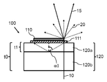
도 1은 제1 광 변환 모듈(100)의 단면의 주요한 스케치를 도시한다. 제1 광 변환 모듈(100)은 특히 제1 파장 범위(예를 들어, 청색 레이저 광) 내의 레이저 광(10)을 제1 파장 범위와는 다른 제2 파장 범위(예를 들어, 황색 광) 내의 변환된 레이저 광(20)으로 변환하기 위한 변환 층(110)을 포함한다. 변환 층(110)으로 변환되지 않은 레이저 광(10)의 일부는 투과된 레이저 광(15)이 변환 층(110)에 충돌하는 레이저 광(10)으로서 더 넓은 광 분포를 특징으로 하도록 변환 층(110)에서 산란된다. 제1 광 변환 모듈(100)은 두께 t0을 갖는 기판(120), 및 기판(120)과 변환 층(110) 사이에 배열된 반사 층(111)을 더 포함한다. 반사 층(111)은 미리 정의된 각도 범위 내에서 반사 층(111)에 충돌하는 변환된 레이저 광(20)이 기판(120)으로 들어갈 수 없도록 제2 파장 범위에서 반사성이다. 반사 층(111) 및 기판의 광 출사면을 통해 기판(120)으로 입사하는 변환된 레이저 광(20)이 기판(120)의 평행 광 입사면을 통해 기판(120)을 떠날 수 있도록, 제1 광 변환 모듈(100)은 기판의 광 입사면(레이저 광(10)이 기판(120)으로 입사하는 면)에 배열되는 반사 방지 코팅(130)을 더 포함한다. 특히, 광 입사면에서의 변환된 레이저 광(20)의 부분 반사는 반사 방지 코팅(130)에 의해 방지되거나 적어도 감소될 수 있다. 또한, 광대역 반사 방지 코팅(130)에 의해 기판(120)의 광 입사면에서 레이저 광(10)의 반사를 방지할 수 있다.Figure 1 shows a major sketch of a cross-section of a first
제1 면에 수직인 층의 두께(t0)는 적어도 t0=d/(2*tan(α1))이고, 여기서 d는 레이저 광(10)을 수용할 수 있는 광 출사면에 평행한 변환 층(110)의 가장 큰 또는 최대 연장 범위이다. 각도(α1)는 기판 재료의 굴절률 및 기판(120)의 광 입사면에 인접하는 재료의 굴절률에 대한 제2 파장 범위에서의 전반사 각도이다. 두께 t0는 기판(120)의 광 입사면에서 전반사된 변환된 레이저 광(20)이 변환 층(110)에 의해 덮인 광 출사면의 영역에 충돌하지 않도록 선택된다. 변환 층(110)은 정면 상에, 또는 더 정확하게는 기판(120)의 광 출사면 상에, 예를 들어 투명 실리콘 글루에 의해 글루잉된 얇은 인광체 층(예를 들어 25㎛ 두께)을 포함한다. 두꺼운 기판(120)의 재료는 바람직하게는 사파이어이다. 공기에 대한 전반사 임계각 α1은 33.7°이다. 10×20mm2의 횡방향 치수를 갖는 인광체 또는 변환 층(110)은 22.4㎜의 대각선을 갖는다. 그러면, 위 공식에 의해 최소 기판 두께는 t0=16.73mm로 된다. 안전 여백을 포함하여 두께 t0=20mm를 선택할 수 있다. 기판(120)은 이 실시예에서 직사각 입체의 형상을 갖는다. 단면은 22.4mm의 대각선을 따라 취해진다.The thickness t0 of the layer perpendicular to the first surface is at least t0 = d / (2 * tan (alpha 1)), where d is a conversion layer parallel to the light exit surface capable of accommodating the
변환 층(110)은 정의된 타겟 또는 타겟 영역의 조명을 가능하게 할 수 있는 임의의 형상(위에서 논의된 바와 같이 반드시 직사각형일 필요는 없음)을 포함할 수 있다.The
도 2는 제2 광 변환 모듈(100)의 정면도의 주요한 스케치를 도시한다. 이 경우, 기판(120)은 두께 t0=17mm를 갖는 원통 형상을 갖는다. 레이저 광(10)을 수용할 수 있는 기판(120)의 광 출사면에 평행한 변환 층(110)의 최대 연장 범위(d)와 함께, 기판(120)과 변환 층(110) 사이의 실린더 최상부 상에 반사 층(111)이 제공된다. 원통형 기판(120)의 횡방향 크기는 25mm의 지름을 특징으로 한다. 본 예의 기판의 원통 형상은 단지 표준 광기계적(optomechanical) 홀더들에의 장착을 용이하게 하도록 선택되었다. 초과된 부피는 실제로 필요하지는 않다. 횡방향 치수는 인광체 층보다 클 필요는 없다.Figure 2 shows the main sketches of the front view of the second
도 3은 제3 광 변환 모듈(100)의 단면의 주요한 스케치를 도시한다. 제3 광 변환 모듈(100)의 구성은 도 1과 관련하여 논의된 구성과 거의 동일하다. 기판(120)은 제2 파장 범위에서 흡수성인 사파이어로 구성된다. 이 경우, 청색 레이저 광(10)을 투과시키지만 황색 변환된 레이저 광을 흡수하는 청색 사파이어 재료를 제공하기 위해, 사파이어 재료에 크롬이 첨가될 수 있다. 기판(120)은 기판(120)의 광 출사면에 수직인 두께 t0가 22mm이고 광 입사 및 광 출사면의 크기가 12x22mm2인 직사각형 블록이다. 기판(120)의 4개의 측면들은 1.5의 굴절률을 갖는 투명 수지를 포함하는 반사 감소 구조체(140)에 의해 덮힌다. 반사 감소 구조체(140)에 입사하는 황색 광, 또는 더 정확하게는 제2 파장 범위 내의 광을 흡수하기 위해 탄소 조각들(flakes)이 수지에 첨가된다. 제1 파장 범위의 광이 제어되지 않은 방식으로 변환 층(110)에 입사할 가능성을 방지하거나 적어도 감소시키기 위해, 청색 광 또는 제1 파장 범위의 광은 흡수될 것이다.3 shows a major sketch of a cross-section of the third
도 4는 제4 광 변환 모듈(100)의 단면의 주요한 스케치를 도시한다. 제4 광 변환 모듈은 두께 t1 및 20W/(mK) 초과의 열전도도를 갖는 열 전도성 재료의 제1 기판 층(120a) 및 제1 기판 층(120a)에 열적으로 본딩된 제2 기판 층(120b)을 갖는 기판(120)을 포함한다. 기판(120)의 총 두께는 t0이다. 두께 t1은 제1 기판 층(120a)과 제2 기판 층(120b) 사이의 경계면에서 전반사된 변환된 레이저 광(20)이 변환 층(110)에 충돌하지 않도록 정해진다. 굴절률의 차이는 제1 기판 층(120a)의 두께를 감소시킨다. 사파이어의 굴절률이 1.78이고 제2 기판 층의 굴절률을 1.46(실리카의 굴절률)로 잡으면, 전반사 각도는 약 56.5°이다. 도 1에 관하여 설명된 바와 같이 변환 층(110)의 연장 범위를 10x20mm2로 하고 사파이어 층의 두께가 적어도 7.5mm인 경우, 변환 층(110)으로의 후방 반사를 초래하는 2개의 층 사이의 계면에서의 전반사는 방지된다.4 shows a major sketch of a cross section of the fourth
최소 두께(t0)는 위에서 설명한 바와 같이 제1 기판 층(120a)의 재료의 굴절률 및 제2 기판 층(120b)의 재료의 굴절률에 의존한다. 기판(120)의 총 두께(t0)는 기판(120)의 광 출사면으로부터 회피된, 기판(120)의 광 입사면에서 전반사된 변환된 레이저 광(20)이 변환 층(110)에 충돌하지 않도록 다시 정해진다. 변환 층(110)은 변환 층(110)과 기판(120) 사이에 배열된 반사 층(111)에 다시 부착된다. 제1 기판 층(120a)은 예를 들어 1.78의 굴절률을 갖는 사파이어를 포함할 수 있다. 제2 기판 층(120b)은 예를 들어 1.46의 굴절률을 갖는 실리카를 포함할 수 있다. 실리카 층은 황색으로 변환된 레이저 광(20)을 흡수하기 위해 흡수성일 수 있다.The minimum thickness t0 depends on the refractive index of the material of the
제2 기판 층(120b)은 대안적인 실시예에서 사파이어의 굴절률과 거의 동일한 굴절률을 갖는 유리(SF-11)를 포함할 수 있다. 이 경우, 사파이어 층의 두께는 변환 층(110)(예를 들어, 1mm의 두께)에 충분한 냉각을 제공하기 위해 필요한 절대적인 최소값으로 감소될 수 있다. 기판이 하나의 굴절률을 특징으로 하기 때문에, 이 경우 기판의 총 두께는 위에서 논의된 바(t0는 적어도 16.73mm임)와 동일할 것이다.The
예를 들어, 레이저는 20W의 청색 레이저 광을 갖는 레이저 광(10)을 방출할 수 있고, 20W 레이저 광(10) 중 10.5W는 열로 변환될 수 있다. 2cm2의 크기를 갖는 변환 층(110)의 면적 및 25㎛의 변환 층(110)의 두께를 취하면, 제1 기판 층(120a)이 두께 1mm이고 열전도도가 40W/(mK)인 사파이어를 포함하는 경우, 이는 얇은 변환 층(110)의 횡방향 중심과 기판(120)의 측면들 사이에 20℃의 온도 차를 초래한다. 제2 기판 층(120b)은 이 예에서 두께가 20mm이고 열전도도가 1.38W/(mK)인 실리카 층이다. 이 시뮬레이션에서, 레이저 스폿이 변환 층(110)을 가로질러 충분히 빠르게 이동하므로, 본질적으로 변환 층으로부터 사파이어 층으로의 열 흐름이 일정하다고 가정한다. 보수적으로 사파이어 층의 열 전도도는 30W/(mK)로 가정된다.For example, the laser may emit
도 5는 제5 광 변환 모듈(100)의 단면의 주요 스케치를 도시한다. 제5 광 변환 모듈(100)은 도 2에 관하여 논의된 바와 같이 기판(120), 반사 층(111), 및 변환 층(110)을 포함한다. 기판(120)은 원통 형상이고 광 입사면은 만곡부로 되어 있다. 광 입사면의 곡률은 광 입사면이 제1 파장 범위의 광을 방출하는 광원(예를 들어, 하나 이상의 레이저 또는 대응하는 스캐너)이 위치할 수 있는 초점을 정의하도록 선택된다. 따라서, 기판(120)의 광 입사면에서 제1 파장 범위의 광의 반사가 감소될 수 있다.5 shows a major sketch of a cross-section of the fifth
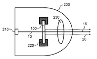
도 6은 예를 들어 도 2에 관하여 위에서 설명한 바와 같은 광 변환 모듈(100)을 포함하는 레이저 기반 광원(200)의 주요 스케치를 도시한다. 레이저 기반 광원(200)은 제1 파장 범위 내의 레이저 광(10)을 방출하는 레이저 모듈(210)을 포함한다. 광 변환 모듈(100)의 기판(120)은 변환 프로세스에 의해 발생된 열을 확산시키도록 구성된 히트 싱크(220)에 의해 둘러싸여있다. 레이저 기반 광원(200)은 렌즈, 반사기 등과 같은 하나 이상의 광학 요소를 포함할 수 있는 광학 디바이스(230)를 더 포함한다. 광학 디바이스(230)는 투과된 레이저 광(15) 및 변환된 레이저 광(20)을 타겟 영역에 이미징되도록 배열된다. 레이저 모듈(210)은 강한 청색 레이저 빔을 방출하기 위한 적어도 하나의 레이저를 포함할 수 있다. 적어도 하나의 레이저는 전자적으로 스위칭될 수 있고 레이저 광(10)의 방향은 변환 층(110)을 가로질러 레이저 빔을 이동시키기 위해 작은 미러, 전형적으로 마이크로 전기 기계 시스템 (micro electromechanical system, MEMS)에 의해 제어될 수 있다.FIG. 6 illustrates a major sketch of a laser-based
대안적으로, 레이저 모듈(210)은 2개, 3개 또는 그 이상의 스위칭 가능한 레이저 또는 심지어 레이저 어레이를 포함할 수 있다.Alternatively, the
도 6에 도시된 레이저 기반 광원(200)은 바람직하게는 거리들 및 그 주변들을 조명하기 위한 자동차 전조등이다. 다가오는 트래픽(traffic)이나 다른 트래픽 참가자의 눈부심을 최소화하면서 높은 밝기를 가능하게 하는 적응형 광 패턴을 제공하기 위해 레이저 제어가 사용된다.The laser-based
도 7은 광 변환 모듈을 제조하는 방법의 주요한 스케치를 도시한다. 위에서 설명된 투명 기판(120)은 단계(310)에서 제공된다. 변환 층(110)은 단계(320)에서 투명 기판(120)의 광 출사면에 부착된다. 변환 층(110)은 광 입사면을 통해 기판에 입사하는 제1 파장 범위의 레이저 광(10)을, 제1 파장 범위와 다른 제2 파장 범위의 변환된 레이저 광(20)으로 변환하도록 배열된다. 기판은 단계(330)에서 광 출사면을 통해 기판으로 입사되는 변환된 레이저 광이 광 출사면을 통해 변환 층으로 재입사하는 것을 억제하도록 배열된다.Figure 7 shows a major sketch of a method of manufacturing a light conversion module. The
추가적인 제조 단계에서 반사 층(111)이 기판(120)과 변환 층(110) 사이에 배열될 수 있다.The
본 발명의 기본 사상은 레이저 기반 광원(200) 내에서 사용될 때 최대 에지 대비를 가능하게 하는 광 변환 모듈(100)을 제공하는 것이다. 레이저 기반 광원(200)은 바람직하게는 자동차 전조등이다. 변환 층(110)에 직접 또는 간접적으로 부착된 기판(120)의 두께는, 변환 층(110)이 제1 파장 범위 내의 레이저 광(10)(예를 들어 청색 레이저 광)에 의해 단지 부분적으로만 조명될 때 최대 에지 대비가 달성되도록 증가된다. 다가오는 트래픽에 할애하기 위해 예를 들어 전조등 빔 또는 번들에서 완전히 어두운 영역을 생성하기 위해서, 변환 층(110) 또는 인광체의 부분적 어두움이 필요하다. 대비의 최대화는 변환 층(110)의 레이저-조명 영역으로부터 어두운 영역으로의 광의 임의의 누설 또는 확산을 본질적으로 방지하는 것을 의미한다. 이러한 광 누설의 일부는 변환 층(110) 또는 인광체 자체 때문일 수 있다. 제2 파장 영역 내의 변환된 레이저 광(20)(예를 들어, 황색 광)은 먼저 등방성으로 방출되고, 황색 광이 변환 층(110) 내에서 확산되는 것을 방지하기 위해 주의를 기울여야 한다. 따라서 재료에서의 산란이 증가될 수 있다. 대안적으로 또는 부가적으로 변환 층(110)은 가능한 한 얇게 만들어질 수 있다.The basic idea of the present invention is to provide a
그러나, 변환 층이 이러한 방식으로 최적화되면, 광 누설의 중요한 원인으로서 남아있는 것은 투명한 기판(120)이다. 기판(120)의 존재는 필수적이다. 기판이 없으면, 얇은 변환 층(110) 또는 인광체 층은 기계적으로 안정하지 않을 것이고, 기판(120)으로의 열전도에 의해 냉각되어 유지될 수도 없다. 기판에 의한 광의 누설은 다음의 메커니즘에 기인한다. 청색 레이저 스캐닝 빔의 스폿에서 발생하는 황색 광은 기판(120)을 향하는 것을 포함하는 모든 방향으로 방출된다. 변환 층(110)과 기판(120) 사이의 광학 접촉으로 인해, 그것은 투명 기판(120)의 후면 또는 광 입사면에 전반사 각도 미만으로 충돌할 수 있고, 스폿으로부터 멀리 떨어진 변환 층(110)으로 다시 반사될 것이다. 전반사된 변환된 레이저 광(20)은 또한 변환 층(110)을 빠져 나갈 수 있으며, 이러한 방식으로 변환 층(110)의 조명되지 않은 부분에서 원하지 않는 광을 생성할 수 있다. 본 발명은 기판의 후면에서 전반사된 변환된 레이저 광(20)이 조명에 사용될 수 있는 변환 층(110)의 영역 요소에 충돌하지 않도록, 스폿과 역반사된 변환된 레이저 광(20) 사이의 거리를 증가시키는 두께 t0를 가지는 기판(120)을 제공하는 것을 제안한다. 따라서, 변환 층(110)의 조명되지 않은 부분은 어둡다.However, once the conversion layer is optimized in this way, what remains a significant source of light leakage is the
본 발명은 도면들 및 전술한 설명에서 상세하게 도시되고 설명되었지만, 그러한 도시 및 설명은 도시적이거나 예시적인 것이고, 제한적이지 않은 것으로 간주되어야 한다.While the present invention has been shown and described in detail in the drawings and foregoing description, such city and description are to be considered illustrative or exemplary and not restrictive.
본 개시 내용을 읽음으로써, 본 기술분야의 통상의 기술자에게는 다른 변경들이 명백할 것이다. 그러한 변경들은 본 기술분야에 이미 공지되어 있고 본 명세서에 이미 설명된 특징들 대신에 또는 그러한 특징들에 추가하여 사용될 수 있는 다른 특징을 포함할 수 있다.Upon reading the present disclosure, other modifications will be apparent to those of ordinary skill in the art. Such modifications may include other features that are well known in the art and may be used in place of or in addition to the features already described herein.
개시된 실시예들에 대한 변화들은 도면, 개시내용, 및 첨부된 청구 범위의 연구로부터 본 기술분야의 통상의 기술자에 의해 이해되고 영향을 받을 수 있다. 청구 범위에서, "포함하는(comprising)"이라는 단어는 다른 요소 또는 단계를 배제하지 않으며, 부정 관사 "a" 또는 "an"은 복수의 요소 또는 단계를 배제하지 않는다. 특정 수단이 서로 다른 종속항들에서 인용된다는 단순한 사실이 이러한 수단들의 조합을 유리하게 사용할 수 없다는 것을 지시하지는 않는다.Changes to the disclosed embodiments can be understood and effected by those skilled in the art from study of the drawings, disclosure, and appended claims. In the claims, the word " comprising " does not exclude other elements or steps, and the word " a " or " an " does not exclude a plurality of elements or steps. The mere fact that certain measures are quoted in different dependent claims does not indicate that a combination of these measures can not be used to advantage.
청구 범위 내의 임의의 참조 부호는 그것의 범위를 제한하는 것으로 해석되어서는 안 된다.Any reference signs in the claims shall not be construed as limiting the scope thereof.
10 레이저 광
15 투과된 레이저 광
20 변환된 레이저 광
100 광 변환 모듈
110 변환 층
111 반사 층
120 기판
120a 제1 기판 층
120b 제2 기판 층
130 반사 방지 코팅
140 반사 감소 구조체
200 레이저 기반 광원
210 레이저 모듈
220 히트 싱크
230 광학 디바이스
310 기판을 제공하는 단계
320 변환 층을 부착하는 단계
330 기판을 배열하는 단계
t0 기판 두께
t1 제1 기판 층의 두께
α1 전반사 각도
d 변환 층의 횡방향 최대 연장 범위10 laser light
15 Transmitted laser light
20 converted laser light
100 photoconversion module
110 conversion layer
111 reflective layer
120 substrate
120a first substrate layer
120b second substrate layer
130 anti-reflective coating
140 reflection reduction structure
200 Laser-based light source
210 Laser Module
220 heat sink
230 optical device
310 substrate
320 < / RTI >
330 arranging the substrate
t0 substrate thickness
t1 thickness of the first substrate layer
d transverse direction maximum extension range
Claims (15)
투명 기판(120); 및
상기 기판(120)의 광 출사면에 부착된 변환 층(110)
을 포함하고,
상기 변환 층(110)은
광 입사면을 통해 기판(120)에 입사하는 제1 파장 범위의 레이저 광(10)의 일부를 상기 제1 파장 범위와는 다른 제2 파장 범위의 변환된 레이저 광(20)으로 변환시키고,
투과된 레이저 광(15) 및 상기 변환된 레이저 광(20)의 일부의 혼합물이, 상기 변환 층(110)이 상기 기판(120)의 상기 광 출사면에 부착되는 면에 반대되는 순방향으로 상기 변환 층(110)을 떠나도록, 상기 레이저 광(10)의 다른 부분을 투과시키도록 배열되고,
상기 기판(120)은 상기 기판(120)의 상기 광 입사면에서 전반사되는 상기 기판(120)으로 입사되는 상기 변환된 레이저 광(20)이 상기 광 입사면에서의 1회의 전반사 이후 상기 변환 층(110)에 충돌하지 않도록 상기 광 출사면에 수직한 상기 기판(120)의 두께를 정하여, 상기 광 출사면을 통해 상기 기판에 입사하는 상기 변환된 레이저 광(20)이 상기 변환 층(110)에 재입사하는 것을 억제하도록 배열되는, 광 변환 모듈(100).As the photo-conversion module 100,
A transparent substrate 120; And
A conversion layer 110 attached to the light output surface of the substrate 120,
/ RTI >
The conversion layer (110)
A part of the laser light 10 in the first wavelength range incident on the substrate 120 through the light incident surface is converted into the converted laser light 20 in the second wavelength range different from the first wavelength range,
A mixture of the transmitted laser light 15 and a part of the converted laser light 20 is converted by the conversion in the forward direction opposite to the plane in which the conversion layer 110 is attached to the light output surface of the substrate 120. [ Is arranged to transmit the other part of the laser light (10) so as to leave the layer (110)
The substrate 120 may be configured such that the converted laser light 20 incident on the substrate 120, which is totally reflected by the light incident surface of the substrate 120, (120) perpendicular to the light exit surface so as not to collide with the conversion layer (110), and the converted laser light (20) incident on the substrate through the light exit surface is transferred to the conversion layer And is arranged to suppress reincidence.
제1항 내지 제12항 중 어느 한 항에 따른 상기 광 변환 모듈(100),
레이저 모듈(210), 및
광학 디바이스(230)
를 포함하고,
상기 광 변환 모듈(100)은 상기 레이저 모듈(210)과 상기 광학 디바이스(230) 사이에 배열되고,
상기 레이저 기반 광원(200)은, 상기 레이저 모듈(210)에 의해 방출된 상기 제1 파장 범위 내의 레이저 광(10)이 상기 광 입사면을 통해 상기 기판(120)에 입사하고 상기 광 출사면을 통해 상기 기판(120)을 떠나도록 배열되고,
상기 레이저 기반 광원(200)은 상기 변환 층(110)을 통과하는 투과된 레이저 광(15) 및 변환된 레이저 광(20)의 적어도 일부가 상기 광학 디바이스(230)에 의해 타겟 영역으로 이미징되도록 더 배열되는, 레이저 기반 광원(200).As a laser-based light source 200,
13. A device according to any one of claims 1 to 12,
Laser module 210, and
Optical device 230,
Lt; / RTI >
The light conversion module 100 is arranged between the laser module 210 and the optical device 230,
The laser-based light source 200 is configured such that the laser light 10 within the first wavelength range emitted by the laser module 210 is incident on the substrate 120 through the light incident surface, And is arranged to leave the substrate (120)
The laser-based light source 200 is further adapted to cause at least a portion of the transmitted laser light 15 and the converted laser light 20 passing through the conversion layer 110 to be imaged by the optical device 230 into the target area A laser-based light source (200) comprising:
투명 기판(120)을 제공하는 단계;
상기 기판(120)의 광 출사면에 변환 층(110)을 부착하는 단계;
광 입사면을 통해 상기 기판(120)에 입사하는 제1 파장 범위의 레이저 광(10)의 일부를 상기 제1 파장 범위와는 다른 제2 파장 범위의 변환된 레이저 광(20)으로 변환하고,
상기 레이저 광(10)의 다른 일부를 투과시키도록
상기 변환 층(110)을 배열하여, 레이저 광(15) 및 변환된 레이저 광(20)의 일부의 혼합물이, 상기 변환 층(110)이 상기 기판(120)의 상기 광 출사면에 부착되는 면에 반대되는 순 방향으로 상기 변환 층(110)을 떠나게 하는 단계; 및
상기 기판(120)의 상기 광 입사면에서 전반사되는 상기 기판(120)에 입사하는 상기 변환된 레이저 광(20)이 상기 광 입사면에서의 1회의 전반사 이후 상기 변환 층(110)에 충돌하지 않도록 상기 광 출사면에 수직한 상기 기판(120)의 두께를 정하여, 상기 광 출사면을 통해 상기 기판에 입사하는 상기 변환된 레이저 광(20)이 상기 광 출사면을 통해 상기 변환 층(110)으로 재입사하는 것을 억제하도록 기판(120)을 배열하는 단계
를 포함하는, 광 변환 모듈(100)을 제조하는 방법.A method of manufacturing a photoconversion module (100)
Providing a transparent substrate (120);
Attaching a conversion layer (110) to a light exit surface of the substrate (120);
A part of the laser light 10 in the first wavelength range incident on the substrate 120 through the light incident surface is converted into the converted laser light 20 in the second wavelength range different from the first wavelength range,
To transmit a different part of the laser light 10
The conversion layer 110 is arranged so that a mixture of the laser light 15 and a part of the converted laser light 20 is incident on the surface of the conversion layer 110 which is attached to the light output surface of the substrate 120 Leaving the conversion layer (110) in a forward direction opposite to that of the conversion layer (110). And
The converted laser light 20 incident on the substrate 120 which is totally reflected by the light incident surface of the substrate 120 is prevented from colliding with the conversion layer 110 after total reflection once on the light incident surface The thickness of the substrate 120 perpendicular to the light output surface is determined and the converted laser light 20 incident on the substrate through the light output surface passes through the light output surface to the conversion layer 110 Arranging the substrate 120 so as to suppress the re-
(100). ≪ / RTI >
Applications Claiming Priority (3)
| Application Number | Priority Date | Filing Date | Title |
|---|---|---|---|
| EP15202568 | 2015-12-23 | ||
| EP15202568.0 | 2015-12-23 | ||
| PCT/EP2016/080560 WO2017108463A1 (en) | 2015-12-23 | 2016-12-12 | Light conversion module |
Publications (2)
| Publication Number | Publication Date |
|---|---|
| KR20180098590A true KR20180098590A (en) | 2018-09-04 |
| KR102631223B1 KR102631223B1 (en) | 2024-01-31 |
Family
ID=55070770
Family Applications (1)
| Application Number | Title | Priority Date | Filing Date |
|---|---|---|---|
| KR1020187020989A Active KR102631223B1 (en) | 2015-12-23 | 2016-12-12 | optical conversion module |
Country Status (7)
| Country | Link |
|---|---|
| US (1) | US10260695B2 (en) |
| EP (1) | EP3394903B1 (en) |
| JP (1) | JP6929850B2 (en) |
| KR (1) | KR102631223B1 (en) |
| CN (1) | CN108474536B (en) |
| TW (1) | TWI724086B (en) |
| WO (1) | WO2017108463A1 (en) |
Cited By (1)
| Publication number | Priority date | Publication date | Assignee | Title |
|---|---|---|---|---|
| KR20210071247A (en) * | 2019-12-06 | 2021-06-16 | 신동현 | laser lamp for mirror |
Families Citing this family (6)
| Publication number | Priority date | Publication date | Assignee | Title |
|---|---|---|---|---|
| EP3555689B1 (en) * | 2016-12-14 | 2024-06-05 | Lumileds LLC | Light converting device |
| JP2019109330A (en) * | 2017-12-18 | 2019-07-04 | パナソニックIpマネジメント株式会社 | Wavelength conversion device, light source apparatus, illumination apparatus and projection type video display apparatus |
| US10288800B1 (en) * | 2018-12-08 | 2019-05-14 | Tactotek Oy | Multilayer structure with embedded light source and light-guiding features and related method of manufacture |
| CN111724692B (en) * | 2020-05-12 | 2022-06-10 | 深圳市隆利科技股份有限公司 | Display capable of being spliced |
| CN112133812A (en) * | 2020-09-15 | 2020-12-25 | 湖州市汉新科技有限公司 | High thermal conductivity fluorescent film, preparation method and application in LED or laser lighting |
| CN112420899B (en) * | 2020-09-29 | 2022-06-14 | 湖州市汉新科技有限公司 | High-color rendering index high-thermal conductivity fluorescent film, preparation method and application in display equipment |
Citations (4)
| Publication number | Priority date | Publication date | Assignee | Title |
|---|---|---|---|---|
| JP2012243701A (en) * | 2011-05-24 | 2012-12-10 | Stanley Electric Co Ltd | Light source device and lighting system |
| JP2014207436A (en) * | 2013-03-18 | 2014-10-30 | 日本碍子株式会社 | Wavelength converter |
| WO2014178398A1 (en) * | 2013-04-30 | 2014-11-06 | シャープ株式会社 | Lighting device |
| JP2015149394A (en) * | 2014-02-06 | 2015-08-20 | スタンレー電気株式会社 | Wavelength conversion body and light-emitting device using the same |
Family Cites Families (11)
| Publication number | Priority date | Publication date | Assignee | Title |
|---|---|---|---|---|
| WO2011007816A1 (en) * | 2009-07-15 | 2011-01-20 | 三菱化学株式会社 | Semiconductor light-emitting element, semiconductor light-emitting device, method for manufacturing semiconductor light-emitting element, and method for manufacturing semiconductor light-emitting device |
| US8154052B2 (en) | 2010-05-06 | 2012-04-10 | Koninklijke Philips Electronics N.V. | Light emitting device grown on wavelength converting substrate |
| WO2012015013A1 (en) * | 2010-07-29 | 2012-02-02 | 旭化成株式会社 | Television receiver and surface light source device |
| DE102013200521B4 (en) * | 2013-01-15 | 2024-03-21 | Automotive Lighting Reutlingen Gmbh | Primary optical device for motor vehicle headlights with laser light source, layer-like photoluminescence element, light-guiding element and reflection surfaces for light from the photoluminescence element and corresponding motor vehicle headlights |
| FR3002023B1 (en) * | 2013-02-14 | 2015-03-20 | Valeo Vision | SECURE ADAPTIVE LIGHTING SYSTEM |
| GB201306351D0 (en) * | 2013-04-09 | 2013-05-22 | Gen Dynamics Broadband Inc | Apparatus and methods for device to device communications |
| WO2014203484A1 (en) * | 2013-06-21 | 2014-12-24 | パナソニックIpマネジメント株式会社 | Wavelength conversion member, light source and vehicle headlamp |
| AT514438B1 (en) * | 2013-07-04 | 2015-01-15 | Zizala Lichtsysteme Gmbh | vehicle headlights |
| KR102108994B1 (en) * | 2013-08-30 | 2020-05-12 | 삼성전자주식회사 | Light conversion device and manufacturing method thereof, and light source unit having the same |
| TWI540377B (en) * | 2014-01-29 | 2016-07-01 | 台達電子工業股份有限公司 | Optical wavelength converter and illumination system using same |
| DE102014202863A1 (en) * | 2014-02-17 | 2015-08-20 | Osram Gmbh | Lighting device with conversion device |
-
2016
- 2016-12-12 US US16/064,967 patent/US10260695B2/en active Active
- 2016-12-12 CN CN201680075688.7A patent/CN108474536B/en active Active
- 2016-12-12 EP EP16819453.8A patent/EP3394903B1/en active Active
- 2016-12-12 KR KR1020187020989A patent/KR102631223B1/en active Active
- 2016-12-12 WO PCT/EP2016/080560 patent/WO2017108463A1/en not_active Ceased
- 2016-12-12 JP JP2018532453A patent/JP6929850B2/en active Active
- 2016-12-23 TW TW105143098A patent/TWI724086B/en active
Patent Citations (4)
| Publication number | Priority date | Publication date | Assignee | Title |
|---|---|---|---|---|
| JP2012243701A (en) * | 2011-05-24 | 2012-12-10 | Stanley Electric Co Ltd | Light source device and lighting system |
| JP2014207436A (en) * | 2013-03-18 | 2014-10-30 | 日本碍子株式会社 | Wavelength converter |
| WO2014178398A1 (en) * | 2013-04-30 | 2014-11-06 | シャープ株式会社 | Lighting device |
| JP2015149394A (en) * | 2014-02-06 | 2015-08-20 | スタンレー電気株式会社 | Wavelength conversion body and light-emitting device using the same |
Cited By (1)
| Publication number | Priority date | Publication date | Assignee | Title |
|---|---|---|---|---|
| KR20210071247A (en) * | 2019-12-06 | 2021-06-16 | 신동현 | laser lamp for mirror |
Also Published As
| Publication number | Publication date |
|---|---|
| US10260695B2 (en) | 2019-04-16 |
| CN108474536A (en) | 2018-08-31 |
| KR102631223B1 (en) | 2024-01-31 |
| EP3394903A1 (en) | 2018-10-31 |
| TWI724086B (en) | 2021-04-11 |
| CN108474536B (en) | 2021-07-13 |
| EP3394903B1 (en) | 2024-04-17 |
| JP2019502951A (en) | 2019-01-31 |
| JP6929850B2 (en) | 2021-09-01 |
| US20180372293A1 (en) | 2018-12-27 |
| TW201801353A (en) | 2018-01-01 |
| WO2017108463A1 (en) | 2017-06-29 |
Similar Documents
| Publication | Publication Date | Title |
|---|---|---|
| KR102631223B1 (en) | optical conversion module | |
| JP6742445B2 (en) | Headlight device | |
| US10514151B2 (en) | Light-emitting device, illumination device, and vehicle headlamp | |
| KR101847932B1 (en) | Lighting device module | |
| JP4047266B2 (en) | Lamp | |
| CN103443534B (en) | Motor vehicle headlight with multifunctional projection module | |
| EP2159479B1 (en) | Vehicle lamp unit | |
| US9079529B2 (en) | Vehicle lighting unit and light guide lens | |
| KR102155080B1 (en) | Vehicle headlamp | |
| JP2022111358A (en) | headlight device | |
| KR102294317B1 (en) | Light emitting apparatus | |
| CN108291702B (en) | Light source device, lighting device and vehicle lamp | |
| US9822943B2 (en) | Lamp unit | |
| US10684004B2 (en) | Lamp unit | |
| CN111373195B (en) | Lighting device for a motor vehicle | |
| JP2014010918A (en) | Luminaire and vehicle headlight | |
| TWI487864B (en) | Radiation-emitting device and use of such device | |
| WO2016175214A1 (en) | Lighting device and optical member | |
| JP6072447B2 (en) | Lighting device and vehicle headlamp | |
| JP2619014B2 (en) | Effect spotlight | |
| JP2007165142A (en) | Vehicle lighting |
Legal Events
| Date | Code | Title | Description |
|---|---|---|---|
| PA0105 | International application |
St.27 status event code: A-0-1-A10-A15-nap-PA0105 |
|
| PG1501 | Laying open of application |
St.27 status event code: A-1-1-Q10-Q12-nap-PG1501 |
|
| A201 | Request for examination | ||
| P11-X000 | Amendment of application requested |
St.27 status event code: A-2-2-P10-P11-nap-X000 |
|
| P13-X000 | Application amended |
St.27 status event code: A-2-2-P10-P13-nap-X000 |
|
| PA0201 | Request for examination |
St.27 status event code: A-1-2-D10-D11-exm-PA0201 |
|
| E701 | Decision to grant or registration of patent right | ||
| PE0701 | Decision of registration |
St.27 status event code: A-1-2-D10-D22-exm-PE0701 |
|
| PR0701 | Registration of establishment |
St.27 status event code: A-2-4-F10-F11-exm-PR0701 |
|
| PR1002 | Payment of registration fee |
St.27 status event code: A-2-2-U10-U12-oth-PR1002 Fee payment year number: 1 |
|
| PG1601 | Publication of registration |
St.27 status event code: A-4-4-Q10-Q13-nap-PG1601 |
|
| P22-X000 | Classification modified |
St.27 status event code: A-4-4-P10-P22-nap-X000 |