KR20180098587A - Flow adjustment mechanism and fluid coupling - Google Patents
Flow adjustment mechanism and fluid coupling Download PDFInfo
- Publication number
- KR20180098587A KR20180098587A KR1020187020719A KR20187020719A KR20180098587A KR 20180098587 A KR20180098587 A KR 20180098587A KR 1020187020719 A KR1020187020719 A KR 1020187020719A KR 20187020719 A KR20187020719 A KR 20187020719A KR 20180098587 A KR20180098587 A KR 20180098587A
- Authority
- KR
- South Korea
- Prior art keywords
- working fluid
- valve rod
- cam
- fluid
- flow rate
- Prior art date
- Legal status (The legal status is an assumption and is not a legal conclusion. Google has not performed a legal analysis and makes no representation as to the accuracy of the status listed.)
- Withdrawn
Links
Images


Classifications
-
- F—MECHANICAL ENGINEERING; LIGHTING; HEATING; WEAPONS; BLASTING
- F16—ENGINEERING ELEMENTS AND UNITS; GENERAL MEASURES FOR PRODUCING AND MAINTAINING EFFECTIVE FUNCTIONING OF MACHINES OR INSTALLATIONS; THERMAL INSULATION IN GENERAL
- F16D—COUPLINGS FOR TRANSMITTING ROTATION; CLUTCHES; BRAKES
- F16D33/00—Rotary fluid couplings or clutches of the hydrokinetic type
- F16D33/06—Rotary fluid couplings or clutches of the hydrokinetic type controlled by changing the amount of liquid in the working circuit
- F16D33/08—Rotary fluid couplings or clutches of the hydrokinetic type controlled by changing the amount of liquid in the working circuit by devices incorporated in the fluid coupling, with or without remote control
- F16D33/10—Rotary fluid couplings or clutches of the hydrokinetic type controlled by changing the amount of liquid in the working circuit by devices incorporated in the fluid coupling, with or without remote control consisting of controllable supply and discharge openings
-
- F—MECHANICAL ENGINEERING; LIGHTING; HEATING; WEAPONS; BLASTING
- F16—ENGINEERING ELEMENTS AND UNITS; GENERAL MEASURES FOR PRODUCING AND MAINTAINING EFFECTIVE FUNCTIONING OF MACHINES OR INSTALLATIONS; THERMAL INSULATION IN GENERAL
- F16D—COUPLINGS FOR TRANSMITTING ROTATION; CLUTCHES; BRAKES
- F16D33/00—Rotary fluid couplings or clutches of the hydrokinetic type
- F16D33/06—Rotary fluid couplings or clutches of the hydrokinetic type controlled by changing the amount of liquid in the working circuit
- F16D33/08—Rotary fluid couplings or clutches of the hydrokinetic type controlled by changing the amount of liquid in the working circuit by devices incorporated in the fluid coupling, with or without remote control
- F16D33/14—Rotary fluid couplings or clutches of the hydrokinetic type controlled by changing the amount of liquid in the working circuit by devices incorporated in the fluid coupling, with or without remote control consisting of shiftable or adjustable scoops
-
- F—MECHANICAL ENGINEERING; LIGHTING; HEATING; WEAPONS; BLASTING
- F16—ENGINEERING ELEMENTS AND UNITS; GENERAL MEASURES FOR PRODUCING AND MAINTAINING EFFECTIVE FUNCTIONING OF MACHINES OR INSTALLATIONS; THERMAL INSULATION IN GENERAL
- F16H—GEARING
- F16H41/00—Rotary fluid gearing of the hydrokinetic type
- F16H41/24—Details
Landscapes
- Engineering & Computer Science (AREA)
- General Engineering & Computer Science (AREA)
- Mechanical Engineering (AREA)
- Mechanically-Actuated Valves (AREA)
Abstract
본 발명은 유체 커플링의 작동유체의 유량을 조정하는 유량 조정 기구에 관한 것이다. 또한, 본 발명은 이와 같은 유량 조정 기구를 구비한 유체 커플링에 관한 것이다. 유량 조정 기구(60)는 작동유체 순환 라인(27)에 연통되는 유로(76)를 갖는 하우징(75)과, 유로(76) 내에 이동 가능하게 수용된 밸브체(71)와, 임펠러(1)와 러너(2) 사이에 형성되는 유체실(5) 내에 있는 작동유체의 양을 조정하기 위한 스쿠프 튜브(30)와 일체로 이동 가능한 캠(80)과, 일단이 캠(80)에 접촉하고, 타단이 밸브체(71)에 접속된 밸브 로드(72)를 구비한다.The present invention relates to a flow rate adjusting mechanism for adjusting a flow rate of a working fluid of a fluid coupling. The present invention also relates to a fluid coupling including such a flow rate adjusting mechanism. The flow rate adjusting mechanism 60 includes a housing 75 having a flow path 76 communicating with the working fluid circulating line 27, a valve body 71 movably received in the flow path 76, A cam 80 integrally movable with the scoop tube 30 for adjusting the amount of the working fluid in the fluid chamber 5 formed between the runners 2; And a valve rod 72 connected to the valve body 71.
Description
본 발명은 유체 커플링의 작동유체의 유량을 조정하는 유량 조정 기구에 관한 것이다. 또한, 본 발명은 이와 같은 유량 조정 기구를 구비한 유체 커플링에 관한 것이다.The present invention relates to a flow rate adjusting mechanism for adjusting a flow rate of a working fluid of a fluid coupling. The present invention also relates to a fluid coupling including such a flow rate adjusting mechanism.
유체 커플링은, 입력측 날개 바퀴인 임펠러와, 출력측 날개 바퀴인 러너 사이에 존재하는 작동유체를 통해 입력축의 회전을 출력축에 전달하는 장치이다. 작동유체로는, 예를 들어 작동유가 사용된다. 임펠러와 러너 사이에 존재하는 작동유체의 양을 증감함으로써, 입력축에 대한 출력축의 회전 속도를 무단계로 바꿀 수 있다.The fluid coupling is a device for transmitting the rotation of the input shaft to the output shaft through a working fluid existing between an impeller, which is an input side impeller, and a runner, which is an output impeller. As the working fluid, for example, hydraulic fluid is used. The rotational speed of the output shaft relative to the input shaft can be steplessly changed by increasing or decreasing the amount of working fluid present between the impeller and the runner.
유체 커플링은 임펠러와 러너 사이에 형성되는 유체실 내에 있는 작동유체의 양을 증감시키기 위한 스쿠프 튜브(퍼올리기 관)를 구비하고 있다. 유체실 내의 작동유체의 양은 스쿠프 튜브의 위치에 의존하여 바뀐다. 스쿠프 튜브를 이동시킴으로써, 작동유체의 양, 즉, 출력축의 회전 속도를 바꿀 수 있다.The fluid coupling has a scoop tube (raising tube) for increasing or decreasing the amount of working fluid in the fluid chamber formed between the impeller and the runner. The amount of working fluid in the fluid chamber varies depending on the location of the scoop tube. By moving the scoop tube, the amount of working fluid, that is, the rotational speed of the output shaft, can be changed.
유체 커플링은 작동유체를 냉각하기 위한 유체 냉각 장치와, 유체 냉각 장치를 관통하여 연장되는 작동유체 순환 라인을 더 구비하고 있다. 작동유체 순환 라인의 입구는 스쿠프 튜브에 접속되어 있고, 작동유체 순환 라인의 출구는 유체실에 연통되어 있다. 스쿠프 튜브를 통해 배출된 작동유체는 작동유체 순환 라인을 흘러 유체 냉각 장치에서 냉각된 후, 다시 작동유체 순환 라인을 통해 유체실로 복귀된다. 이와 같이, 작동유체는 유체실과 유체 냉각 장치 사이에서 순환된다.The fluid coupling further includes a fluid cooling device for cooling the working fluid and a working fluid circulating line extending through the fluid cooling device. The inlet of the working fluid circulation line is connected to the scoop tube, and the outlet of the working fluid circulating line is in communication with the fluid chamber. The working fluid discharged through the scoop tube flows through the working fluid circulating line and is cooled in the fluid cooling device, and then returned to the fluid room through the working fluid circulating line. As such, the working fluid is circulated between the fluid chamber and the fluid cooling device.
유체 커플링은 스쿠프 튜브를 이동시킴으로써, 출력축의 회전 속도를 저속으로부터 고속까지 무단계로 변화시킬 수 있는 장치이지만, 임펠러와 러너 사이에는 미끄럼 손실이 발생하는 것이 알려져 있다. 유체 커플링을 구비한 터보 기계를 구동하는 경우, 입력축의 회전 속도에 대하여 출력축이 66.7%의 속도비로 회전하고 있을 때, 미끄럼 손실은 가장 커지고, 작동유체의 발열량도 커진다. 이로 인해, 작동유체 순환 라인을 흐르는 작동유체의 유량을 증가시켜, 유체실 내의 작동유체의 온도 상승을 억제할 필요가 있다. 이에 대해, 입력축의 회전 속도에 대하여 출력축이 최저 회전 속도 또는 최고 회전 속도로 회전하고 있을 때, 미끄럼 손실은 작으므로, 작동유체의 교반 손실을 저감시켜 효율을 양호하게 하기 위해, 작동유체의 유량은 적은 편이 바람직하다.The fluid coupling is a device capable of steplessly changing the rotational speed of the output shaft from low speed to high speed by moving the scoop tube, but it is known that sliding loss occurs between the impeller and the runner. In the case of driving a turbomachine having a fluid coupling, when the output shaft rotates at a speed ratio of 66.7% with respect to the rotational speed of the input shaft, the slip loss becomes largest and the amount of heat generated by the working fluid also increases. Accordingly, it is necessary to increase the flow rate of the working fluid flowing through the working fluid circulation line, and to suppress the temperature rise of the working fluid in the fluid chamber. On the other hand, since the sliding loss is small when the output shaft rotates at the minimum rotation speed or the maximum rotation speed with respect to the rotation speed of the input shaft, in order to reduce the agitation loss of the working fluid and improve the efficiency, Smaller is preferable.
이와 같은 관점에서, 출력축의 회전 속도, 즉, 스쿠프 튜브의 위치에 따라 작동유체의 유량을 조정할 필요가 있다. 그러나, 종래, 작동유체의 유량을 조정하는 기구는 복잡했다.From this point of view, it is necessary to adjust the flow rate of the working fluid according to the rotation speed of the output shaft, that is, the position of the scoop tube. However, conventionally, the mechanism for adjusting the flow rate of the working fluid has been complicated.
본 발명은 상술한 사정을 감안하여 이루어진 것으로, 간단한 구조로 작동유체의 유량을 용이하게 조정할 수 있는 유량 조정 기구를 제공하는 것을 목적으로 한다. 또한, 본 발명은 이와 같은 유량 조정 기구를 구비한 유체 커플링을 제공하는 것을 목적으로 한다.SUMMARY OF THE INVENTION It is an object of the present invention to provide a flow rate adjusting mechanism capable of easily adjusting a flow rate of a working fluid with a simple structure. It is another object of the present invention to provide a fluid coupling including such a flow rate adjusting mechanism.
상술한 목적을 달성하기 위해, 본 발명의 일 형태는, 유체 커플링의 작동유체의 유량을 조정하는 유량 조정 기구이며, 작동유체 순환 라인에 연통되는 유로를 갖는 하우징과, 상기 유로 내에 이동 가능하게 수용된 밸브체와, 임펠러와 러너 사이에 형성되는 유체실 내에 있는 상기 작동유체의 양을 조정하기 위한 스쿠프 튜브와 일체로 이동 가능한 캠과, 일단이 상기 캠에 접촉하고, 타단이 상기 밸브체에 접속된 밸브 로드를 구비하는 것을 특징으로 한다.According to one aspect of the present invention, there is provided a flow rate adjusting mechanism for adjusting a flow rate of a working fluid of a fluid coupling, comprising: a housing having a flow path communicating with a working fluid circulating line; A cam that is integrally moveable with a scoop tube for adjusting the amount of the working fluid in a fluid chamber formed between the impeller and the runner; one end contacting the cam and the other end being connected to the valve body And a valve rod provided in the valve body.
본 발명의 바람직한 양태는, 상기 밸브 로드의 상기 일단은 상기 캠에 구름 접촉하는 캠 팔로워로 구성되어 있는 것을 특징으로 한다.A preferred embodiment of the present invention is characterized in that the one end of the valve rod is constituted by a cam follower which comes into rolling contact with the cam.
본 발명의 바람직한 양태는, 상기 캠은 오목한 만곡면으로 구성되어 있는 것을 특징으로 한다.A preferred embodiment of the present invention is characterized in that the cam is constituted by concave curved surfaces.
본 발명의 바람직한 양태는, 상기 밸브 로드가 그 축방향으로 이동 가능하도록 상기 밸브 로드를 지지하는 밸브 로드 가이드를 더 구비하고, 상기 밸브 로드 가이드 및 상기 밸브 로드는 상기 유로의 개구단을 막고 있고, 상기 밸브체에는 균압 구멍이 형성되어 있는 것을 특징으로 한다.A preferred embodiment of the present invention further comprises a valve rod guide for supporting the valve rod such that the valve rod is movable in an axial direction thereof, wherein the valve rod guide and the valve rod block the open end of the flow passage, And a pressure equalizing hole is formed in the valve body.
본 발명의 다른 양태는, 서로 마주 보며 배치된 임펠러 및 러너와, 상기 임펠러와 상기 러너 사이에 형성되는 유체실 내에 있는 작동유체의 양을 조정하는 스쿠프 튜브와, 작동유체를 냉각하는 유체 냉각 장치와, 상기 유체실과 상기 유체 냉각 장치 사이에서 작동유체를 순환시키는 작동유체 순환 라인과, 상기 작동유체 순환 라인을 순환하는 작동유체의 유량을 조정하는 유량 조정 기구를 구비하고, 상기 유량 조정 기구는, 상기 작동유체 순환 라인에 연통되는 유로를 갖는 하우징과, 상기 유로 내에 이동 가능하게 수용된 밸브체와, 상기 스쿠프 튜브와 일체로 이동 가능한 캠과, 일단이 상기 캠에 접촉하고, 타단이 상기 밸브체에 접속된 밸브 로드를 구비하는 것을 특징으로 하는 유체 커플링이다.Another aspect of the present invention is directed to a fluid machine comprising: an impeller and a runner disposed opposite each other; a scoop tube for adjusting the amount of working fluid in a fluid chamber formed between the impeller and the runner; A working fluid circulating line for circulating a working fluid between the fluid chamber and the fluid cooling device; and a flow rate adjusting mechanism for adjusting a flow rate of the working fluid circulating the working fluid circulating line, A valve body movably housed in the flow passage; a cam movable integrally with the scoop tube; one end contacting the cam; the other end contacting the valve body; And a valve body having a valve body.
본 발명의 바람직한 양태는, 상기 밸브 로드의 상기 일단은 상기 캠에 구름 접촉하는 캠 팔로워로 구성되어 있는 것을 특징으로 한다.A preferred embodiment of the present invention is characterized in that the one end of the valve rod is constituted by a cam follower which comes into rolling contact with the cam.
본 발명의 바람직한 양태는, 상기 캠은 오목한 만곡면으로 구성되어 있는 것을 특징으로 한다.A preferred embodiment of the present invention is characterized in that the cam is constituted by concave curved surfaces.
본 발명의 바람직한 양태는, 상기 유량 조정 기구는 상기 밸브 로드가 그 축방향으로 이동 가능하도록 상기 밸브 로드를 지지하는 밸브 로드 가이드를 더 구비하고, 상기 밸브 로드 가이드 및 상기 밸브 로드는 상기 유로의 개구단을 막고 있고, 상기 밸브체에는 균압 구멍이 형성되어 있는 것을 특징으로 한다.In a preferred aspect of the present invention, the flow rate adjusting mechanism further comprises a valve rod guide for supporting the valve rod such that the valve rod is movable in an axial direction thereof, and the valve rod guide and the valve rod And a valve seat is formed in the valve body.
본 발명에 따르면, 스쿠프 튜브와 일체로 이동 가능한 캠에 밸브 로드의 일단이 접촉하고, 밸브 로드의 타단에는 밸브체가 접속되어 있기 때문에, 스쿠프 튜브의 움직임에 연동하여 밸브 로드 및 밸브체가 이동된다. 따라서, 간단한 구조로, 작동유체 순환 라인을 흐르는 작동유체의 유량을 용이하게 조정할 수 있다.According to the present invention, since one end of the valve rod is in contact with the cam that can be moved integrally with the scoop tube, and the valve body is connected to the other end of the valve rod, the valve rod and the valve body are moved in conjunction with the movement of the scoop tube. Therefore, with a simple structure, the flow rate of the working fluid flowing through the working fluid circulation line can be easily adjusted.
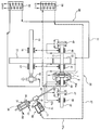
도 1은 본 발명의 유체 커플링의 일 실시 형태를 모식적으로 도시하는 평면도이다.
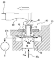
도 2는 유량 조정 기구를 도시하는 단면도이다.
도 3은 스쿠프 튜브가 전진했을 때의 캠 및 캠 팔로워를 도시하는 도면이다.
도 4는 스쿠프 튜브가 후퇴했을 때의 캠 및 캠 팔로워를 도시하는 도면이다.1 is a plan view schematically showing an embodiment of a fluid coupling of the present invention.
2 is a sectional view showing a flow rate adjusting mechanism.
3 is a view showing a cam and a cam follower when the scoop tube is advanced.
4 is a view showing a cam and a cam follower when the scoop tube is retracted.
이하, 본 발명의 실시 형태에 대하여 도면을 참조하여 설명한다. 도 1은 본 발명의 유체 커플링의 일 실시 형태를 모식적으로 도시하는 평면도이다. 도 1에 도시한 바와 같이, 유체 커플링은 서로 마주 보며 배치된 임펠러(1) 및 러너(2)와, 임펠러(1)가 고정된 구동축(11)과, 러너(2)가 고정된 출력축(12)을 구비한다. 임펠러(1)는 입력측 날개 바퀴, 러너(2)는 출력측 날개 바퀴라고도 불린다. 임펠러(1) 및 러너(2)는 각각 내측에 복수의 방사형 날개를 갖는 반구 형상을 갖고 있고, 임펠러(1)와 러너(2) 사이에는 유체실(5)이 형성된다.Hereinafter, embodiments of the present invention will be described with reference to the drawings. 1 is a plan view schematically showing an embodiment of a fluid coupling of the present invention. 1, the fluid coupling includes an impeller 1 and a
구동축(11)과 평행으로 입력축(15)이 배치되어 있다. 이 입력축(15)은 레이디얼 베어링(16, 17)에 의해 지지되어 있다. 입력축(15)에는 기어 휠(21)이 고정되고, 구동축(11)에는 기어 휠(21)에 맞물리는 피니언(22)이 고정되어 있다. 입력축(15)의 단부는 도시하지 않은 원동기(전동기나 가스 터빈 등)에 접속되어 있다. 원동기의 회전은 입력축(15)으로부터 기어 휠(21) 및 피니언(22)을 통해 구동축(11)으로 전달된다.And the
유체 커플링은 임펠러(1)와 러너(2) 사이에 형성되는 유체실(5)에 작동유체를 공급하는 작동유체 순환 시스템(25)과, 유체실(5) 내에 있는 작동유체의 양을 증감시키기 위한 스쿠프 튜브(퍼올리기 관)(30)를 더 구비하고 있다. 이 스쿠프 튜브(30)의 선단(30a)은 임펠러 케이싱(7) 내에 위치하고 있다. 임펠러 케이싱(7)은 임펠러(1)에 고정되고, 러너(2)를 둘러싸는 형상을 갖고 있다. 임펠러 케이싱(7)은 임펠러(1)와 함께 회전한다.The fluid coupling includes an operating
스쿠프 튜브(30)에는 액추에이터(구동 장치)(31)가 접속되어 있고, 이 액추에이터(31)에 의해 스쿠프 튜브(30)는 임펠러(1) 및 러너(2)의 반경 방향으로 이동 가능하게 되어 있다. 본 실시 형태에서는, 액추에이터(31)는 유압 서보와 전기식 또는 공기식 액추에이터의 조합으로 구성되어 있지만, 액추에이터(31)는 다른 구성을 구비해도 된다. 임펠러(1) 및 임펠러 케이싱(7)이 회전하고 있을 때, 작동유체(예를 들어, 작동유)는 회전하는 임펠러 케이싱(7)에 보유 지지된다. 이 임펠러 케이싱(7) 내의 작동유체는 회전하는 임펠러(1)에 의해 유동하고, 이 유동한 작동유체가 러너(2)를 회전시킨다.An
임펠러(1)가 회전하고 있을 때, 작동유체에는 원심력이 발생하여, 작동유체의 압력이 높아진다. 스쿠프 튜브(30)의 선단(30a)은 임펠러 케이싱(7) 내의 작동유체를 퍼내고, 작동유체는 스쿠프 튜브(30) 내를 통해 임펠러 케이싱(7)으로부터 배출된다. 작동유체 순환 시스템(25)은 작동유체를 냉각하기 위한 유체 냉각 장치(26)와, 이 유체 냉각 장치(26)를 관통하여 연장되는 작동유체 순환 라인(27)을 구비하고 있다. 작동유체 순환 라인(27)의 입구는 스쿠프 튜브(30)에 접속되어 있고, 작동유체 순환 라인(27)의 출구는 임펠러(1)와 러너(2) 사이의 유체실(5)에 연통되어 있다.When the impeller 1 is rotating, a centrifugal force is generated in the working fluid, so that the pressure of the working fluid is increased. The
임펠러 케이싱(7)으로부터 스쿠프 튜브(30)를 통해 배출된 작동유체는 작동유체 순환 라인(27)을 흘러 유체 냉각 장치(26)로 보내진다. 작동유체는 냉각수와의 열교환에 의해 냉각된 후, 다시 작동유체 순환 라인(27)을 통해 유체실(5)로 복귀된다. 이와 같이, 작동유체는 회전하는 임펠러(1)에 의해 상승된 자신의 압력에 의해, 유체실(5)과 유체 냉각 장치(26) 사이를 순환한다.The working fluid discharged from the impeller casing 7 through the
임펠러(1)는 구동축(11)에 고정되어 있고, 러너(2)는 출력축(12)에 고정되어 있다. 구동축(11)의 회전은 임펠러(1)로부터 작동유체를 통해 러너(2)로 전달되어, 출력축(12)이 회전한다. 러너(2)의 회전 속도는 임펠러(1)와 러너(2) 사이에 형성된 유체실(5) 내의 작동유체의 양에 따라 변화된다. 구체적으로는, 작동유체의 양이 많을수록, 러너(2)의 회전 속도는 높아진다.The impeller 1 is fixed to the
유체실(5) 내의 작동유체의 양은 스쿠프 튜브(30)의 위치에 의존하여 바뀐다. 즉, 스쿠프 튜브(30)의 선단(30a)이 반경 방향 외측으로 이동하면, 작동유체의 양이 감소하고, 스쿠프 튜브(30)의 선단(30a)이 반경 방향 내측으로 이동하면, 작동유체의 양이 증가한다. 이와 같이, 액추에이터(31)로 스쿠프 튜브(30)를 조작함으로써, 유체실(5) 내의 작동유체의 양, 즉, 출력축(12)의 회전 속도를 바꿀 수 있다.The amount of working fluid in the fluid chamber (5) varies depending on the position of the scoop tube (30). That is, when the
임펠러(1)의 회전에 의해 작동유체에 원심력이 부여되면, 작동유체의 압력이 높아져, 임펠러(1) 및 러너(2)에는 스러스트력이 작용한다. 따라서, 구동축(11)은 2개의 레이디얼 베어링(40, 41) 및 하나의 스러스트 베어링(42)에 의해 회전 가능하게 지지되어 있다. 마찬가지로, 출력축(12)도, 2개의 레이디얼 베어링(45, 46) 및 1개의 스러스트 베어링(47)에 의해 회전 가능하게 지지되어 있다.When the centrifugal force is applied to the working fluid by the rotation of the impeller 1, the pressure of the working fluid becomes high, and the thrust force acts on the impeller 1 and the
유체 커플링은 레이디얼 베어링(16, 17, 40, 41, 45, 46) 및 스러스트 베어링(42, 47)에 윤활유를 공급하는 윤활유 공급 시스템(50)을 구비하고 있다. 윤활유 공급 시스템(50)은 윤활유를 냉각하기 위한 오일 냉각 장치(54)와, 이 오일 냉각 장치(54)를 관통하여 연장되는 윤활유 공급 라인(51)과, 윤활유 공급 라인(51)에 접속된 오일 펌프(53)를 구비하고 있다. 본 실시 형태에서는, 오일 펌프(53)는 입력축(15)에 연결되고, 입력축(15)의 회전에 수반하여 운전되는 기어 펌프이다. 일 실시 형태에서는, 오일 펌프(53)는 전동기에 의해 입력축(15)의 회전과는 독립하여 구동되는 펌프여도 된다. 윤활유는 오일 펌프(53)에 의해 윤활유 공급 라인(51)을 통해 오일 냉각 장치(54)로 이송되고, 여기서 냉각수에 의해 냉각된다. 냉각된 윤활유는, 다시 윤활유 공급 라인(51)을 통해 레이디얼 베어링(40, 41, 45, 46) 및 스러스트 베어링(42, 47)에 공급된다. 냉각된 윤활유는 입력축(15)을 지지하는 레이디얼 베어링(16, 17)에도 공급된다.The fluid coupling has a
스쿠프 튜브(30)는 액추에이터(31)에 의해 구동된다. 이 액추에이터(31)는 실린더(35)와, 실린더(35) 내에 배치되어, 스쿠프 튜브(30)에 접속된 피스톤(38)을 구비한다. 실린더(35)에는 스쿠프 튜브(30)를 이동시키는 오일을 실린더(35) 내에 공급하기 위한 급유 라인(57) 및 실린더(35)에 공급된 오일을 배출하기 위한 배유 라인(58)이 접속되어 있다. 피스톤(38) 및 스쿠프 튜브(30)는 실린더(35) 내에 공급된 오일의 압력에 의해 전진 및 후퇴된다.The
유체 커플링은 작동유체 순환 라인(27)을 순환하는 작동유체의 유량을 조정하는 유량 조정 기구(60)를 더 구비하고 있다. 유체 냉각 장치(26)를 통과한 작동유체는 작동유체 순환 라인(27) 및 유량 조정 기구(60)를 흘러, 유체실(5) 내에 공급된다.The fluid coupling further includes a flow rate adjusting mechanism (60) for adjusting the flow rate of the working fluid circulating through the working fluid circulating line (27). The working fluid that has passed through the
도 2는 유량 조정 기구(60)를 도시하는 단면도이다. 유량 조정 기구(60)는 작동유체 순환 라인(27)에 연통되는 유로(76)를 갖는 하우징(75)과, 유로(76) 내에 이동 가능하게 수용된 밸브체(71)와, 스쿠프 튜브(30)와 일체로 이동 가능한 캠(80)과, 일단이 캠(80)에 접촉하고, 타단이 밸브체(71)에 접속된 밸브 로드(72)를 구비하고 있다. 캠(80)은 스쿠프 튜브(30)와 일체적으로 스쿠프 튜브(30)에 형성되어도 되고, 스쿠프 튜브(30)와는 별체로서, 스쿠프 튜브(30)에 설치되어도 된다.2 is a sectional view showing the flow
하우징(75)은 작동유체 순환 라인(27)의 상류측 구간(27a)에 접속된 작동유체 입구(75a)와, 작동유체 순환 라인(27)의 하류측 구간(27b)에 연통되는 작동유체 출구(75b)를 갖고 있다. 유로(76), 작동유체 입구(75a) 및 작동유체 출구(75b)는 서로 연통되어 있다. 작동유체 순환 라인(27)의 상류측 구간(27a)을 흐른 작동유체는 작동유체 입구(75a)를 통해 하우징(75)의 유로(76) 내에 유입되고, 작동유체 출구(75b)를 통해 유로(76)로부터 배출되고, 작동유체 순환 라인(27)의 하류측 구간(27b)을 통해 유체실(5)로 보내진다.The
도 2에 도시한 바와 같이, 밸브 로드(72)의 일단은 캠(80)에 구름 접촉하는 캠 팔로워(81)로 구성되어 있고, 밸브 로드(72)의 타단은 밸브체(71)에 접속되어 있다. 밸브체(71)는 도시하지 않은 나사에 의해 밸브 로드(72)의 타단에 고정되어 있다. 밸브 로드(72)는 스쿠프 튜브(30)에 대하여 수직으로 연장되어 있다. 또한, 밸브 로드(72)의 일단은 캠(80)에 접촉 가능하면, 캠(80)에 구름 접촉하는 캠 팔로워(81)로 구성되어 있지 않아도 된다.2, one end of the
유량 조정 기구(60)는 밸브 로드(72)가 그 축방향(길이 방향)으로 이동 가능하도록 밸브 로드(72)를 지지하는 밸브 로드 가이드(73)를 더 구비하고 있다. 밸브 로드(72)의 움직임은 밸브 로드 가이드(73)에 의해 직진 운동으로 제한된다. 밸브 로드(72)가 직진 운동하는 방향은 밸브 로드(72)의 축방향(길이 방향)이다. 밸브체(71)는 밸브 로드(72)와 일체로 이동한다. 밸브 로드 가이드(73)는 케이싱 등의 고정 부재(33)에 고정되어 있고, 밸브 로드 가이드(73) 및 밸브 로드(72)는 유로(76)의, 작동유체 입구(75a)와는 반대측의 개구단을 막고 있다.The flow
캠(80)은 오목한 만곡면으로 구성되어 있다. 스쿠프 튜브(30)가 그 길이 방향으로 이동하면, 캠 팔로워(81)는 캠(80)의 형상을 따라 이동하고, 밸브 로드(72) 및 밸브체(71)는 캠 팔로워(81)와 일체로 이동한다. 즉, 스쿠프 튜브(30)가 움직임으로써, 밸브체(71)가 하우징(75)의 유로(76) 내를 이동한다.The
유체 냉각 장치(26)에 의해 냉각된 작동유체는 작동유체 순환 라인(27)의 상류측 구간(27a)을 통해 하우징(75)의 작동유체 입구(75a)로부터 유로(76) 내로 유입된다. 작동유체는 하우징(75)의 작동유체 출구(75b)를 통과하여 작동유체 순환 라인(27)의 하류측 구간(27b)을 통해 유체실(5) 내에 공급된다. 본 실시 형태에서는, 복수의 작동유체 출구(75b)가 하우징(75)의 둘레 방향을 따라 등간격으로 형성되어 있다. 도 2에는 3개의 작동유체 출구(75b)가 도시되어 있지만, 작동유체 출구(75b)의 수 및 형상은 본 실시 형태에 한정되지 않는다.The working fluid cooled by the
밸브체(71)는 유로(76)를 형성하는 하우징(75)의 내면에 미끄럼 이동 가능하게 배치되어 있다. 보다 구체적으로는, 밸브체(71)는 밸브체(71)가 작동유체 출구(75b)의 일부를 덮는 위치에 배치되어 있다. 따라서, 유량 조정 기구(60)는 하우징(75) 내의 밸브체(71)의 위치를 바꿈으로써, 작동유체 순환 라인(27)을 흐르는 작동유체의 유량을 조정할 수 있다. 도 2에 도시한 바와 같이, 캠 팔로워(81)가, 오목한 만곡면으로 이루어지는 캠(80)의 중앙 영역에 접촉할 때, 작동유체 출구(75b)의 개구 면적은 가장 커진다.The
도 3은 스쿠프 튜브(30)가 전진했을 때, 즉 스쿠프 튜브(30)가 임펠러(1) 및 러너(2)의 반경 방향 외측으로 이동했을 때의 캠(80) 및 캠 팔로워(81)를 도시하는 도면이고, 도 4는 스쿠프 튜브(30)가 후퇴했을 때, 즉 스쿠프 튜브(30)가 임펠러(1) 및 러너(2)의 반경 방향 내측으로 이동했을 때의 캠(80) 및 캠 팔로워(81)를 도시하는 도면이다.3 shows the
스쿠프 튜브(30)가 도 2에 도시하는 위치로부터 전진 또는 후퇴하면, 캠 팔로워(81)는 캠(80)에 눌려, 밸브 로드(72) 및 밸브체(71)는 일체로 이동한다. 이때, 밸브체(71)는 작동유체 출구(75b)의 대부분을 막는 방향으로 이동한다. 결과적으로, 작동유체 순환 라인(27)을 순환하는 작동유체의 유량은 저하된다. 도 3 및 도 4에 도시하는 예에서는, 캠 팔로워(81)는 만곡면으로 이루어지는 캠(80)의 단부 영역에 접촉하고 있다. 이때, 하우징(75)의 작동유체 출구(75b)의 개구 면적은 가장 작아진다. 작동유체 출구(75b)는 밸브체(71)에 의해 완전히 폐쇄되지는 않아, 유체실(5) 내에는 항상 작동유체가 공급된다.When the
밸브체(71)에는 하우징(75)의 유로(76) 내를 흐르는 작동유체의 압력이 작용한다. 따라서, 캠 팔로워(81)가 캠(80)의 중앙 영역을 향하는 방향으로 스쿠프 튜브(30)가 이동하면, 캠 팔로워(81)는 캠(80)을 누르면서, 밸브체(71)는 작동유체 출구(75b)를 개방하는 방향으로 이동한다. 결과적으로, 작동유체 순환 라인(27)을 순환하는 작동유체의 유량은 증가한다.The pressure of the working fluid flowing in the
밸브체(71)에는 밸브 로드(72)의 축방향으로 연장되는 복수의 균압 구멍(71a)이 형성되어 있다. 이들 균압 구멍(71a)은 관통 구멍이고, 밸브체(71)의 둘레 방향으로 등간격으로 배열되어 있다. 밸브체(71)가 이동할 때, 작동유체의 일부는 균압 구멍(71a)을 통해 이동하므로, 밸브체(71)는 원활하게 움직일 수 있다. 따라서, 스쿠프 튜브(30)가 이동할 때에, 캠 팔로워(81)로부터 큰 부하가 스쿠프 튜브(30)에 가해지는 것을 방지할 수 있다.A plurality of equalizing
도 2에 도시한 바와 같이, 캠 팔로워(81)가 캠(80)의 중앙 영역에 접촉하고 있을 때, 즉, 입력축(15)의 회전 속도에 대하여 출력축(12)이 66.7%의 속도비로 회전하고 있을 때, 미끄럼 손실은 가장 커지고, 작동유체의 발열량도 커진다. 본 실시 형태에 따르면, 캠 팔로워(81)가 캠(80)의 중앙 영역에 접촉할 때, 작동유체 출구(75b)의 개구 면적은 최대가 되기 때문에, 작동유체 순환 라인(27)을 흐르는 작동유체의 유량을 증가시킬 수 있다. 따라서, 유체실(5) 내의 작동유체의 온도 상승을 억제할 수 있다.The
입력축(15)의 회전 속도에 대하여 출력축(12)이 최저 회전 속도 또는 최고 회전 속도로 회전하고 있을 때, 미끄럼 손실은 작으므로, 작동유체의 교반 손실을 저감시켜 효율을 양호하게 하기 위해, 작동유체의 유량은 적은 편이 바람직하다. 본 실시 형태에 따르면, 캠 팔로워(81)가 캠(80)의 단부 영역에 접촉하고 있을 때, 즉, 출력축(12)이 고속 또는 저속으로 회전하고 있을 때, 작동유체 순환 라인(27)을 흐르는 작동유체의 양을 저감시킬 수 있다. 따라서, 유체 커플링의 효율을 향상시킬 수 있다.Since the slip loss is small when the
이와 같이, 스쿠프 튜브(30)의 이동에 의해 유량 조정 기구(60)를 동작시킴으로써, 적절한 양의 작동유체를 순환시킬 수 있으므로, 작동유체의 발열량을 작게 하고, 또한 작동유체의 교반 손실을 저감시켜 효율을 양호하게 할 수 있다. 특히, 본 실시 형태에 따르면, 스쿠프 튜브(30)와 일체로 이동 가능한 캠(80)을 설치하고, 밸브 로드(72)의 일단을 캠(80)에 접촉시키는 것뿐인 간단한 구조이고, 밸브체(71)를 이동시키기 위한 액추에이터를 설치하는 것은 불필요하다.As described above, by operating the flow
상술한 실시 형태는, 본 발명이 속하는 기술 분야에 있어서의 통상의 지식을 갖는 자가 본 발명을 실시할 수 있는 것을 목적으로 하여 기재된 것이다. 상기 실시 형태의 다양한 변형예는 당업자라면 당연히 이룰 수 있는 것이고, 본 발명의 기술적 사상은 다른 실시 형태에도 적용할 수 있다. 따라서, 본 발명은 기재된 실시 형태에 한정되지 않고, 특허 청구 범위에 의해 정의되는 기술적 사상을 따른 가장 넓은 범위로 해석되는 것이다.The above-described embodiments are described for the purpose of enabling a person having ordinary skill in the art to practice the present invention. Various modifications of the above-described embodiments will be apparent to those skilled in the art, and the technical spirit of the present invention can be applied to other embodiments. Therefore, the present invention is not limited to the embodiments described, but is to be construed as broadest scope according to the technical idea defined by the claims.
본 발명은 유체 커플링의 작동유체의 유량을 조정하는 유량 조정 기구에 이용가능하다. 또한, 본 발명은 이와 같은 유량 조정 기구를 구비한 유체 커플링에 이용 가능하다.The present invention is applicable to a flow rate adjusting mechanism for adjusting the flow rate of working fluid of a fluid coupling. Further, the present invention is applicable to a fluid coupling having such a flow rate adjusting mechanism.
1 : 임펠러
2 : 러너
5 : 유체실
7 : 임펠러 케이싱
11 : 구동축
12 : 출력축
15 : 입력축
16, 17 : 레이디얼 베어링
21 : 기어 휠
22 : 피니언
25 : 작동유체 순환 시스템
26 : 유체 냉각 장치
27 : 작동유체 순환 라인
30 : 스쿠프 튜브(퍼올리기 관)
31 : 액추에이터(구동 장치)
33 : 고정 부재
35 : 실린더
38 : 피스톤
40, 41, 45, 46 : 레이디얼 베어링
42, 47: 스러스트 베어링
50 : 윤활유 공급 시스템
51 : 윤활유 공급 라인
53 : 오일 펌프
54 : 오일 냉각 장치
57 : 급유 라인
58 : 배유 라인
60 : 유량 조정 기구
71 : 밸브체
72 : 밸브 로드
73 : 밸브 로드 가이드
75 : 하우징
75a : 작동유체 입구
75b : 작동유체 출구
76 : 유로
80 : 캠
81: 캠 팔로워1: Impeller
2: Runner
5: fluid chamber
7: Impeller casing
11:
12: Output shaft
15: input shaft
16, 17: Radial bearing
21: Gear wheel
22: Pinion
25: Working fluid circulation system
26: Fluid cooling device
27: working fluid circulation line
30: Scoop tube (lifting pipe)
31: Actuator (driving device)
33: Fixing member
35: Cylinder
38: Piston
40, 41, 45, 46: Radial bearings
42, 47: thrust bearing
50: Lubricant supply system
51: Lubricating oil supply line
53: Oil pump
54: Oil cooling device
57: Lubrication line
58: Drain line
60: Flow adjusting mechanism
71:
72: Valve rod
73: Valve rod guide
75: Housing
75a: working fluid inlet
75b: working fluid outlet
76: Euro
80: Cam
81: Cam followers
Claims (8)
작동유체 순환 라인에 연통되는 유로를 갖는 하우징과,
상기 유로 내에 이동 가능하게 수용된 밸브체와,
임펠러와 러너 사이에 형성되는 유체실 내에 있는 상기 작동유체의 양을 조정하기 위한 스쿠프 튜브와 일체로 이동 가능한 캠과,
일단이 상기 캠에 접촉하고, 타단이 상기 밸브체에 접속된 밸브 로드를 구비하는 것을 특징으로 하는 유량 조정 기구.A flow rate adjusting mechanism for adjusting a flow rate of a working fluid of a fluid coupling,
A housing having a flow passage communicating with the working fluid circulation line,
A valve body movably received in the flow path,
A cam movable integrally with the scoop tube for adjusting the amount of the working fluid in the fluid chamber formed between the impeller and the runner,
And a valve rod having one end in contact with the cam and the other end connected to the valve body.
상기 밸브 로드 가이드 및 상기 밸브 로드는 상기 유로의 개구단을 막고 있고,
상기 밸브체에는 균압 구멍이 형성되어 있는 것을 특징으로 하는 유량 조정 기구.4. The valve apparatus according to any one of claims 1 to 3, further comprising a valve rod guide for supporting the valve rod such that the valve rod is movable in an axial direction thereof,
Wherein the valve rod guide and the valve rod block the open end of the flow passage,
Wherein the valve body is provided with a pressure equalizing hole.
상기 임펠러와 상기 러너 사이에 형성되는 유체실 내에 있는 작동유체의 양을 조정하는 스쿠프 튜브와,
작동유체를 냉각하는 유체 냉각 장치와,
상기 유체실과 상기 유체 냉각 장치 사이에서 작동유체를 순환시키는 작동유체 순환 라인과,
상기 작동유체 순환 라인을 순환하는 작동유체의 유량을 조정하는 유량 조정 기구를 구비하고,
상기 유량 조정 기구는,
상기 작동유체 순환 라인에 연통되는 유로를 갖는 하우징과,
상기 유로 내에 이동 가능하게 수용된 밸브체와,
상기 스쿠프 튜브와 일체로 이동 가능한 캠과,
일단이 상기 캠에 접촉하고, 타단이 상기 밸브체에 접속된 밸브 로드를 구비하는 것을 특징으로 하는 유체 커플링.An impeller and a runner disposed facing each other,
A scoop tube for adjusting an amount of working fluid in a fluid chamber formed between the impeller and the runner,
A fluid cooling device for cooling the working fluid,
A working fluid circulating line for circulating a working fluid between the fluid chamber and the fluid cooling device,
And a flow rate adjusting mechanism for adjusting a flow rate of a working fluid circulating through the working fluid circulating line,
The flow rate adjusting mechanism includes:
A housing having a flow path communicating with the working fluid circulating line;
A valve body movably received in the flow path,
A cam movable integrally with the scoop tube,
And a valve rod having one end in contact with the cam and the other end connected to the valve body.
상기 밸브 로드 가이드 및 상기 밸브 로드는 상기 유로의 개구단을 막고 있고,
상기 밸브체에는 균압 구멍이 형성되어 있는 것을 특징으로 하는 유체 커플링.The valve control apparatus according to any one of claims 5 to 7, wherein the flow rate adjusting mechanism further comprises a valve rod guide for supporting the valve rod such that the valve rod is movable in the axial direction thereof,
Wherein the valve rod guide and the valve rod block the open end of the flow passage,
Wherein the valve body is provided with a pressure equalizing hole.
Applications Claiming Priority (3)
| Application Number | Priority Date | Filing Date | Title |
|---|---|---|---|
| JP2015255350A JP2017116078A (en) | 2015-12-25 | 2015-12-25 | Flow regulating mechanism and fluid coupling |
| JPJP-P-2015-255350 | 2015-12-25 | ||
| PCT/JP2016/081305 WO2017110228A1 (en) | 2015-12-25 | 2016-10-21 | Flow rate adjustment mechanism and fluid coupling |
Publications (1)
| Publication Number | Publication Date |
|---|---|
| KR20180098587A true KR20180098587A (en) | 2018-09-04 |
Family
ID=59089973
Family Applications (1)
| Application Number | Title | Priority Date | Filing Date |
|---|---|---|---|
| KR1020187020719A Withdrawn KR20180098587A (en) | 2015-12-25 | 2016-10-21 | Flow adjustment mechanism and fluid coupling |
Country Status (3)
| Country | Link |
|---|---|
| JP (1) | JP2017116078A (en) |
| KR (1) | KR20180098587A (en) |
| WO (1) | WO2017110228A1 (en) |
Citations (2)
| Publication number | Priority date | Publication date | Assignee | Title |
|---|---|---|---|---|
| JPS6132601U (en) | 1984-07-31 | 1986-02-27 | 三菱重工業株式会社 | rotary pilot valve |
| JPH10196686A (en) | 1996-12-27 | 1998-07-31 | Ebara Corp | Fluid coupling |
Family Cites Families (4)
| Publication number | Priority date | Publication date | Assignee | Title |
|---|---|---|---|---|
| DE1237388B (en) * | 1959-06-02 | 1967-03-23 | Voith Gmbh J M | Flow coupling with adjustable filling level |
| JPS52104079U (en) * | 1976-02-06 | 1977-08-08 | ||
| JPS5872534U (en) * | 1981-11-10 | 1983-05-17 | 株式会社荏原製作所 | variable speed fluid coupling |
| JPS61168334U (en) * | 1985-04-10 | 1986-10-18 |
-
2015
- 2015-12-25 JP JP2015255350A patent/JP2017116078A/en active Pending
-
2016
- 2016-10-21 WO PCT/JP2016/081305 patent/WO2017110228A1/en not_active Ceased
- 2016-10-21 KR KR1020187020719A patent/KR20180098587A/en not_active Withdrawn
Patent Citations (2)
| Publication number | Priority date | Publication date | Assignee | Title |
|---|---|---|---|---|
| JPS6132601U (en) | 1984-07-31 | 1986-02-27 | 三菱重工業株式会社 | rotary pilot valve |
| JPH10196686A (en) | 1996-12-27 | 1998-07-31 | Ebara Corp | Fluid coupling |
Also Published As
| Publication number | Publication date |
|---|---|
| JP2017116078A (en) | 2017-06-29 |
| WO2017110228A1 (en) | 2017-06-29 |
Similar Documents
| Publication | Publication Date | Title |
|---|---|---|
| KR102035544B1 (en) | Speed reducer | |
| US10982676B2 (en) | Coolant pump for the automotive industry | |
| JP6147655B2 (en) | Turbocharger lubrication oil supply mechanism | |
| US4022021A (en) | Constant speed hydraulic motor | |
| KR20200141433A (en) | Automotive Thermal Management Module | |
| EP3851682B1 (en) | Centrifugal compressor and diffuser device | |
| WO2009116380A1 (en) | Hydraulic servo-drive device and variable turbo-supercharger using the same | |
| JP2006312936A (en) | Piston cooling nozzle controlled leakage valve | |
| KR102222343B1 (en) | Methods for regulating liquid injection of a compressor device or expander device, a liquid-injected compressor device or expander device, and a liquid-injected compressor element or expander element | |
| CN104295782A (en) | Relief valve | |
| CN116241457A (en) | High pressure variable vane pump with vane pins | |
| EP2682574A1 (en) | Control valve | |
| KR20180098587A (en) | Flow adjustment mechanism and fluid coupling | |
| EP3290713A1 (en) | Coolant pump for the automotive sector and a coolant circuit for a combustion engine | |
| CN103411121A (en) | Variable fuel pump | |
| RU2749519C2 (en) | Rotary electrohydraulic actuator | |
| NL1039925C2 (en) | SYSTEM FOR ARRANGING A CONTINUALLY VARIABLE TRANSMISSION. | |
| JP5594224B2 (en) | Oil cooling device and machine tool | |
| US11767831B2 (en) | Hydraulic radial piston device | |
| CN107002716A (en) | Actuating drive for a control valve, in particular a steam turbine control valve, and method for operating the same | |
| AU2013312751B2 (en) | Hydraulic motor-driven bearing lubrication system for a centrifugal pump | |
| GB2048385A (en) | A rotary fluid pump or motor | |
| JP2017020562A (en) | Relief valve | |
| CN120720339B (en) | Universal shaft assembly and screw drilling tool | |
| US2350865A (en) | Hydraulic transmission |
Legal Events
| Date | Code | Title | Description |
|---|---|---|---|
| PA0105 | International application |
Patent event date: 20180718 Patent event code: PA01051R01D Comment text: International Patent Application |
|
| PG1501 | Laying open of application | ||
| PC1203 | Withdrawal of no request for examination | ||
| WITN | Application deemed withdrawn, e.g. because no request for examination was filed or no examination fee was paid |