KR20180098497A - Printing apparatus and method for controlling the same, and program - Google Patents
Printing apparatus and method for controlling the same, and program Download PDFInfo
- Publication number
- KR20180098497A KR20180098497A KR1020180098508A KR20180098508A KR20180098497A KR 20180098497 A KR20180098497 A KR 20180098497A KR 1020180098508 A KR1020180098508 A KR 1020180098508A KR 20180098508 A KR20180098508 A KR 20180098508A KR 20180098497 A KR20180098497 A KR 20180098497A
- Authority
- KR
- South Korea
- Prior art keywords
- forming apparatus
- image forming
- power
- finisher
- power saving
- Prior art date
- Legal status (The legal status is an assumption and is not a legal conclusion. Google has not performed a legal analysis and makes no representation as to the accuracy of the status listed.)
- Granted
Links
Images


Classifications
-
- H—ELECTRICITY
- H04—ELECTRIC COMMUNICATION TECHNIQUE
- H04N—PICTORIAL COMMUNICATION, e.g. TELEVISION
- H04N1/00—Scanning, transmission or reproduction of documents or the like, e.g. facsimile transmission; Details thereof
- H04N1/00885—Power supply means, e.g. arrangements for the control of power supply to the apparatus or components thereof
- H04N1/00888—Control thereof
- H04N1/00891—Switching on or off, e.g. for saving power when not in use
-
- B—PERFORMING OPERATIONS; TRANSPORTING
- B41—PRINTING; LINING MACHINES; TYPEWRITERS; STAMPS
- B41J—TYPEWRITERS; SELECTIVE PRINTING MECHANISMS, i.e. MECHANISMS PRINTING OTHERWISE THAN FROM A FORME; CORRECTION OF TYPOGRAPHICAL ERRORS
- B41J2/00—Typewriters or selective printing mechanisms characterised by the printing or marking process for which they are designed
-
- G—PHYSICS
- G03—PHOTOGRAPHY; CINEMATOGRAPHY; ANALOGOUS TECHNIQUES USING WAVES OTHER THAN OPTICAL WAVES; ELECTROGRAPHY; HOLOGRAPHY
- G03G—ELECTROGRAPHY; ELECTROPHOTOGRAPHY; MAGNETOGRAPHY
- G03G15/00—Apparatus for electrographic processes using a charge pattern
- G03G15/65—Apparatus which relate to the handling of copy material
- G03G15/6538—Devices for collating sheet copy material, e.g. sorters, control, copies in staples form
- G03G15/6541—Binding sets of sheets, e.g. by stapling, glueing
-
- B—PERFORMING OPERATIONS; TRANSPORTING
- B25—HAND TOOLS; PORTABLE POWER-DRIVEN TOOLS; MANIPULATORS
- B25C—HAND-HELD NAILING OR STAPLING TOOLS; MANUALLY OPERATED PORTABLE STAPLING TOOLS
- B25C5/00—Manually operated portable stapling tools; Hand-held power-operated stapling tools; Staple feeding devices therefor
- B25C5/10—Driving means
-
- B—PERFORMING OPERATIONS; TRANSPORTING
- B42—BOOKBINDING; ALBUMS; FILES; SPECIAL PRINTED MATTER
- B42B—PERMANENTLY ATTACHING TOGETHER SHEETS, QUIRES OR SIGNATURES OR PERMANENTLY ATTACHING OBJECTS THERETO
- B42B4/00—Permanently attaching together sheets, quires or signatures by discontinuous stitching with filamentary material, e.g. wire
-
- B—PERFORMING OPERATIONS; TRANSPORTING
- B65—CONVEYING; PACKING; STORING; HANDLING THIN OR FILAMENTARY MATERIAL
- B65H—HANDLING THIN OR FILAMENTARY MATERIAL, e.g. SHEETS, WEBS, CABLES
- B65H37/00—Article or web delivery apparatus incorporating devices for performing specified auxiliary operations
- B65H37/04—Article or web delivery apparatus incorporating devices for performing specified auxiliary operations for securing together articles or webs, e.g. by adhesive, stitching or stapling
-
- B—PERFORMING OPERATIONS; TRANSPORTING
- B65—CONVEYING; PACKING; STORING; HANDLING THIN OR FILAMENTARY MATERIAL
- B65H—HANDLING THIN OR FILAMENTARY MATERIAL, e.g. SHEETS, WEBS, CABLES
- B65H43/00—Use of control, checking, or safety devices, e.g. automatic devices comprising an element for sensing a variable
-
- G—PHYSICS
- G03—PHOTOGRAPHY; CINEMATOGRAPHY; ANALOGOUS TECHNIQUES USING WAVES OTHER THAN OPTICAL WAVES; ELECTROGRAPHY; HOLOGRAPHY
- G03G—ELECTROGRAPHY; ELECTROPHOTOGRAPHY; MAGNETOGRAPHY
- G03G15/00—Apparatus for electrographic processes using a charge pattern
- G03G15/50—Machine control of apparatus for electrographic processes using a charge pattern, e.g. regulating differents parts of the machine, multimode copiers, microprocessor control
- G03G15/5004—Power supply control, e.g. power-saving mode, automatic power turn-off
-
- G—PHYSICS
- G03—PHOTOGRAPHY; CINEMATOGRAPHY; ANALOGOUS TECHNIQUES USING WAVES OTHER THAN OPTICAL WAVES; ELECTROGRAPHY; HOLOGRAPHY
- G03G—ELECTROGRAPHY; ELECTROPHOTOGRAPHY; MAGNETOGRAPHY
- G03G15/00—Apparatus for electrographic processes using a charge pattern
- G03G15/65—Apparatus which relate to the handling of copy material
- G03G15/6582—Special processing for irreversibly adding or changing the sheet copy material characteristics or its appearance, e.g. stamping, annotation printing, punching
-
- G—PHYSICS
- G03—PHOTOGRAPHY; CINEMATOGRAPHY; ANALOGOUS TECHNIQUES USING WAVES OTHER THAN OPTICAL WAVES; ELECTROGRAPHY; HOLOGRAPHY
- G03G—ELECTROGRAPHY; ELECTROPHOTOGRAPHY; MAGNETOGRAPHY
- G03G15/00—Apparatus for electrographic processes using a charge pattern
- G03G15/80—Details relating to power supplies, circuits boards, electrical connections
-
- H—ELECTRICITY
- H04—ELECTRIC COMMUNICATION TECHNIQUE
- H04N—PICTORIAL COMMUNICATION, e.g. TELEVISION
- H04N1/00—Scanning, transmission or reproduction of documents or the like, e.g. facsimile transmission; Details thereof
- H04N1/00885—Power supply means, e.g. arrangements for the control of power supply to the apparatus or components thereof
- H04N1/00888—Control thereof
- H04N1/00896—Control thereof using a low-power mode, e.g. standby
-
- H—ELECTRICITY
- H04—ELECTRIC COMMUNICATION TECHNIQUE
- H04N—PICTORIAL COMMUNICATION, e.g. TELEVISION
- H04N1/00—Scanning, transmission or reproduction of documents or the like, e.g. facsimile transmission; Details thereof
- H04N1/00885—Power supply means, e.g. arrangements for the control of power supply to the apparatus or components thereof
- H04N1/00907—Details of supply connection, e.g. arrangement of power cables
-
- G—PHYSICS
- G03—PHOTOGRAPHY; CINEMATOGRAPHY; ANALOGOUS TECHNIQUES USING WAVES OTHER THAN OPTICAL WAVES; ELECTROGRAPHY; HOLOGRAPHY
- G03G—ELECTROGRAPHY; ELECTROPHOTOGRAPHY; MAGNETOGRAPHY
- G03G2215/00—Apparatus for electrophotographic processes
- G03G2215/00362—Apparatus for electrophotographic processes relating to the copy medium handling
- G03G2215/00367—The feeding path segment where particular handling of the copy medium occurs, segments being adjacent and non-overlapping. Each segment is identified by the most downstream point in the segment, so that for instance the segment labelled "Fixing device" is referring to the path between the "Transfer device" and the "Fixing device"
- G03G2215/00379—Copy medium holder
- G03G2215/00392—Manual input tray
Landscapes
- Engineering & Computer Science (AREA)
- Physics & Mathematics (AREA)
- General Physics & Mathematics (AREA)
- Multimedia (AREA)
- Signal Processing (AREA)
- Textile Engineering (AREA)
- Microelectronics & Electronic Packaging (AREA)
- Mechanical Engineering (AREA)
- Control Or Security For Electrophotography (AREA)
- Accessory Devices And Overall Control Thereof (AREA)
- Facsimiles In General (AREA)
- Power Sources (AREA)
Abstract
Description
본 발명은, 화상 형성장치, 그 제어방법과 프로그램에 관한 것이다.The present invention relates to an image forming apparatus, a control method thereof, and a program.
화상 형성장치는, 절전 기능의 향상에 따라, 예를 들면 이하에 나타낸 것과 같은, 복수의 절전 기능을 갖고 있다. 오토매틱 슬립 타이머(automatic sleep timer)는, 유저가 화상 형성장치를 일정 시간 연속해서 사용하지 않은 경우에 화상 형성장치를 슬립 상태로 하는 기능이다. 또한, 오토매틱 슬립 시각은, 유저가 지정한 시각이 되면, 화상 형성장치가 자동으로 슬립 상태로 되는 기능이다. 오토매틱 셧다운 타이머(automatic shut-down timer)는, 유저가 화상 형성장치를 일정 시간 연속해서 사용하지 않을 때에 화상 형성장치의 셧다운 처리를 실행해서 화상 형성장치를 오프 상태로 하는 기능이다. 오토매틱 셧다운 시각은, 유저가 지정한 시간이 되면, 화상 형성장치의 셧다운 처리를 실행해서 화상 형성장치를 오프 상태로 하는 기능이다.The image forming apparatus has a plurality of power saving functions as shown below, for example, in accordance with the improvement of the power saving function. The automatic sleep timer is a function of putting the image forming apparatus into a sleep state when the user does not use the image forming apparatus continuously for a predetermined period of time. In addition, the automatic slip time is a function in which the image forming apparatus automatically enters the sleep state when the time specified by the user is reached. The automatic shut-down timer is a function for turning off the image forming apparatus by executing shutdown processing of the image forming apparatus when the user does not use the image forming apparatus continuously for a predetermined period of time. The automatic shutdown time is a function for shutting down the image forming apparatus to turn off the image forming apparatus at a time designated by the user.
스테이플러(stapler)을 갖는 피니셔(finisher)를 구비한 화상 형성장치에서는, 인쇄한 용지를 스테이플할 수 있다. 이 스테이플러를 갖는 피니셔는, 인쇄한 용지를 스테이플하는 기능과, 화상 형성장치의 인쇄 동작과는 관계없이, 유저가 용지의 삽입구에 용지 다발을 넣어 스테이플시키는 매뉴얼 스테이플 기능 등의 기능을 제공하고 있다.In an image forming apparatus provided with a finisher having a stapler, the printed sheet can be stapled. The finisher having the stapler provides functions such as a function of stapling a printed sheet and a function of a manual staple function in which a user inserts a sheet bundle into a sheet insertion hole and staples the sheet, irrespective of the printing operation of the image forming apparatus.
일본국 특개 2005-107322호 공보에는, 스테이플 기능을 갖는 피니셔 장치에 있어서, 자동 스테이플링과, 매뉴얼 스테이플링을, 모드 스위치를 이용해서 전환하는 것이 기재되어 있다.Japanese Patent Application Laid-Open No. 2005-107322 discloses switching between automatic stapling and manual stapling by using a mode switch in a finisher apparatus having a staple function.
상기한 매뉴얼 스테이플링 기능을 갖는 화상 형성장치에서, 매뉴얼 스테이플링 기능과 절전 기능을 동시에 유효로 하면, 화상 형성장치는 매뉴얼 스테이플링 중에 절전 상태로 이행해 버릴 가능성이 있다. 예를 들면, 유저가 수동으로 스테이플링하는 중에 오토매틱 슬립 타이머가 만료되거나, 오토매틱 슬립 시각이 되면, 화상 형성장치가 절전 상태로 되어, 매뉴얼 스테이플 기능이 중단한다. 또한, 유저가 수동으로 스테이플링하는 중에 오토매틱 셧다운 타이머가 만료되거나, 오토매틱 셧다운 시각이 되면, 화상 형성장치가 셧다운 처리를 실행하여 오프 상태로 된다. 이 경우에도, 매뉴얼 스테이플 기능이 중단한다.In the image forming apparatus having the manual stapling function described above, if the manual stapling function and the power saving function are both made effective, there is a possibility that the image forming apparatus shifts to the power saving state during manual stapling. For example, if the automatic sleep timer expires or the automatic slip time comes while the user manually staples, the image forming apparatus enters a power saving state, and the manual staple function is interrupted. In addition, when the automatic shutdown timer expires while the user manually staples, or when the automatic shutdown time comes, the image forming apparatus executes the shutdown process and turns off. Even in this case, the manual staple function is interrupted.
이것 이외에도, 피니셔와 접속된 화상 형성장치의 경우에는, 화상 형성장치가 슬립 상태나 셧다운 상태로 이행하면, 피니셔에 의해서 실행되는 기능의 실행이 중단된다. 또한, 그와 같은 구성의 화상 형성장치에 있어서, 유저가 피니셔만을 단독으로 사용하고 싶은 경우에도, 화상 형성장치를 슬립 모드로부터 복귀시킬 필요가 있어, 유저에게는 편리하지 않다.In addition, in the case of the image forming apparatus connected to the finisher, when the image forming apparatus shifts to the sleep state or the shutdown state, the execution of the function executed by the finisher is interrupted. Further, in the image forming apparatus having such a configuration, even when the user wants to use only the finisher alone, it is necessary to return the image forming apparatus from the sleep mode, which is not convenient for the user.
본 발명의 목적은, 상기 종래기술의 문제점을 해결하기 위해서, 화상 형성장치가 절전 상태로 되는 것에 의해 피니셔가 중단하는 것을 방지하는 기술을 제공한다.SUMMARY OF THE INVENTION An object of the present invention is to provide a technique for preventing the finisher from being stopped by the image forming apparatus being put into a power saving state in order to solve the problems of the prior art.
본 발명의 일면에 따르면, 피니셔를 접속한 화상 형성장치로서, 상기 화상 형성장치를 절전 상태로 이행시키는 전원 제어수단과, 제본 처리가 행해지는 용지가 상기 피니셔에 유저에 의해서 세트된 것을 검출하면 상기 전원 제어수단에 의해 상기 화상 형성장치가 상기 절전 상태로 이행하는 것을 금지하는 제어수단을 구비하는, 화상 형성장치가 제공된다.According to one aspect of the present invention, there is provided an image forming apparatus connected to a finisher, comprising: power source control means for shifting the image forming apparatus to a power saving state; and power source control means for, when detecting that the sheet, And control means for prohibiting the image forming apparatus from transitioning to the power saving state by the power source control means.
본 발명의 또 다른 일면에 따르면, 피니셔를 접속한 화상 형성장치를 제어하는 제어방법으로서, 상기 화상 형성장치를 절전 상태로 이행시키는 전원 제어단계와, 제본 처리가 행해지는 용지가 상기 피니셔에 유저에 의해서 세트된 것을 검출하면 상기 화상 형성장치가 상기 절전 상태로 이행하는 것을 금지하는 제어단계를 포함하는, 제어방법이 제공된다.According to another aspect of the present invention, there is provided a control method for controlling an image forming apparatus connected to a finisher, comprising: a power control step of shifting the image forming apparatus into a power saving state; And prohibiting the image forming apparatus from transitioning to the power saving state when detecting the set by the image forming apparatus.
본 발명에 따르면, 피니셔가 조작되고 있을 때는, 화상 형성장치가 슬립 상태, 셧다운 상태 등의 절전 상태로 되지 않도록 하여, 화상 형성장치가 절전 상태로 되는 것에 의해 피니셔의 기능이 중단되는 것을 방지할 수 있다.According to the present invention, when the finisher is being operated, the image forming apparatus can be prevented from becoming a power saving state such as a sleep state or a shutdown state, so that the function of the finisher can be prevented from being interrupted have.
본 발명의 추가 특징들은 (첨부도면을 참조하면서) 이하의 예시적인 실시예의 설명으로부터 밝혀질 것이다.Additional features of the invention will be apparent from the following description of exemplary embodiments (with reference to the accompanying drawings).
도 1은 제1 실시예에 따른 화상 형성장치(복합기)의 구성을 설명하는 블록도이다.
도 2는 제1 실시예에 따른 화상 형성장치의 구조를 설명하는 도면이다.
도 3은 제1 실시예에 따른 피니셔의 단면도이다.
도 4는 제1 실시예에 따른 스테이플러의 단면도이다.
도 5는 제1 실시예에 따른 화상 형성장치의 조작부의 평면도이다.
도 6은 제1 실시예에 따른 화상 형성장치의 전원 계통을 설명하는 블록도이다.
도 7은 제1 실시예에 따른 화상 형성장치의 제어부의 구성을 설명하는 블록도이다.
도 8은 제1 실시예에 따른 화상 형성장치가 슬립 상태일 때 발생하는 급전 상태를 설명하는 블록도이다.
도 9는 전원 제어·리셋 회로를 포함하는 도 7의 구성의 일부만 구체적으로 나타낸 블록도이다.
도 10은 제1 실시예에 따른 화상 형성장치가 슬립 상태(절전 상태)로 이행할 때의 처리를 설명하는 플로차트이다.
도 11a는 도 10의 스텝 S1004에서 절전 기능을 실행할 때의 제1 실시예에 따른 처리를 설명하는 플로차트이다.
도 11b는 도 10의 스텝 S1004에서 절전 기능을 실행할 때의 제2 실시예에 따른 처리를 설명하는 플로차트이다.
도 12a는 제3 실시예에 따른 화상 형성장치의 처리를 설명하는 플로차트이다.
도 12b는 제4 실시예에 따른 화상 형성장치의 처리를 설명하는 플로차트이다.
도 13은 제5 실시예에 따른 화상 형성장치의 처리를 설명하는 플로차트이다.
도 14는 제6 실시예에 따른 화상 형성장치의 처리를 설명하는 플로차트이다.
도 15는 제7 실시예에 따른 화상 형성장치의 전원 계통을 설명하는 블록도이다.
도 16은 제7 실시예에 따른 화상 형성장치의 처리를 설명하는 플로차트이다.1 is a block diagram illustrating the configuration of an image forming apparatus (multifunctional apparatus) according to the first embodiment.
2 is a view for explaining a structure of an image forming apparatus according to the first embodiment.
3 is a cross-sectional view of the finisher according to the first embodiment.
4 is a sectional view of the stapler according to the first embodiment.
5 is a plan view of the operating portion of the image forming apparatus according to the first embodiment.
6 is a block diagram illustrating a power supply system of the image forming apparatus according to the first embodiment.
7 is a block diagram illustrating the configuration of the control unit of the image forming apparatus according to the first embodiment.
8 is a block diagram for explaining a power supply state that occurs when the image forming apparatus according to the first embodiment is in the sleep state.
9 is a block diagram specifically showing only part of the configuration of Fig. 7 including the power supply control / reset circuit.
Fig. 10 is a flowchart for explaining processing when the image forming apparatus according to the first embodiment shifts to the sleep state (power saving state).
Fig. 11A is a flowchart for explaining a process according to the first embodiment when executing the power saving function in step S1004 of Fig.
FIG. 11B is a flowchart for explaining the processing according to the second embodiment when executing the power saving function in step S1004 of FIG.
12A is a flowchart for explaining the processing of the image forming apparatus according to the third embodiment.
12B is a flowchart for explaining the processing of the image forming apparatus according to the fourth embodiment.
FIG. 13 is a flowchart for explaining processing of the image forming apparatus according to the fifth embodiment.
Fig. 14 is a flowchart for explaining the processing of the image forming apparatus according to the sixth embodiment.
15 is a block diagram illustrating a power system of the image forming apparatus according to the seventh embodiment.
16 is a flowchart for explaining processing of the image forming apparatus according to the seventh embodiment.
이하, 본 발명의 실시예를 첨부도면을 참조하면서 상세히 설명한다. 이하의 실시예는 첨부된 청구항의 범위를 제한하는 것은 아니며, 이들 실시예에서 설명한 특징들의 조합은 반드시 본 발명의 해결수단에 필수적인 것은 아니라는 점에 유념해야 한다.Hereinafter, embodiments of the present invention will be described in detail with reference to the accompanying drawings. It should be noted that the following embodiments are not intended to limit the scope of the appended claims, and that combinations of the features described in these embodiments are not necessarily essential to the solution of the present invention.
[제1 실시예][First Embodiment]
도 1은, 제1 실시예에 따른 화상 형성장치(복합기)(1)의 구성을 설명하는 블록도다.1 is a block diagram for explaining a configuration of an image forming apparatus (multifunctional apparatus) 1 according to the first embodiment.
화상 형성장치(1)는, 스캐너부(2), 제어부(3), 프린터부(4), 조작부(5), FAX부(7) 등을 구비한다. 스캐너부(2)는, 원고를 판독하여, 그 원고의 화상에 대응하는 화상 데이터를 생성한다. 프린터부(4)는, 화상 데이터에 근거하여 용지(시이트)에 화상을 인쇄한다. 하드 디스크(6)는, 화상 데이터와 제어 프로그램 등을 기억하고 있다. FAX부(7)는 전화 회선 등에 접속해서 화상 데이터(팩시밀리 데이터)의 송수신을 행한다. 제어부(3)는, 이들 각 부에 지시를 출력하여, 이 화상 형성장치(1)의 동작을 제어한다. 또한, 화상 형성장치(1)는 LAN(8)을 통해서 컴퓨터(PC)(9)와의 사이에서의 화상 데이터의 입출력, 잡의 발행, 기기의 지시 등도 행할 수도 있다.The image forming apparatus 1 includes a
스캐너부(2)는, 원고 다발을 적재하고, 원고를 1매씩 스캐너 유닛(22)으로 반송하는 원고 급지 유닛(21)과, 원고를 광학적으로 주사해서 디지털 화상 데이터를 취득하는 스캐너 유닛(22)을 포함한다. 이와 같이 해서 얻어진 화상 데이터는 제어부(3)에 송신된다. 프린터부(4)는, 용지를 1매씩 순차 급지가능한 급지 유닛(42), 급지된 용지에 화상을 인쇄하기 위한 마킹 유닛(41), 인쇄된 용지를 배지하는 배지 유닛(43)을 갖는다.The
피니셔(100)는, 화상 형성장치(1)의 프린터부(4)의 배지 유닛(43)으로부터 배지된 용지에 대하여, 배지, 소팅, 스테이플링, 펀칭, 커팅 등의 후처리를 실시한다. 전원 스위치(101)는, 이 화상 형성장치(1)의 전원의 온/오프를 행하기 위한 스위치이다.The
이하, 이 화상 형성장치(1)가 갖는 기능을 설명한다.Hereinafter, functions of the image forming apparatus 1 will be described.
· 복사 기능· Copy function
스캐너부(2)에 의해서 얻어진 화상 데이터를 하드 디스크(6)에 기억하거나, 프린터부(4)에 의해 인쇄한다.The image data obtained by the
· 화상 송신 기능· Image transmission function
스캐너부(2)에 의해 얻어진 화상 데이터를, LAN(8)을 통해서 컴퓨터(9) 등에 송신한다.And transmits the image data obtained by the
· 화상 보존 기능· Image retention function
스캐너부(2)에 의해서 얻어진 화상 데이터를 하드 디스크(6)에 기억하고, 필요에 따라, 그 화상 데이터를 송신하거나 인쇄한다.The image data obtained by the
· 화상 인쇄 기능· Image printing function
컴퓨터(9)로부터 수신한, 예를 들면 페이지 기술 언어로 기술된 인쇄 잡을 해석해서 프린터부(4)를 이용해서 인쇄한다.For example, a print job described in a page description language, which is received from the
도 2는, 제1 실시예에 따른 화상 형성장치(1)의 구조를 설명하는 도면이다.2 is a view for explaining the structure of the image forming apparatus 1 according to the first embodiment.
스캐너부(2)에 있어서, 원고 급송 유닛(1250)은 원고를 1매씩 글래스 플래튼(glass platen)(1211)에 급송하고, 원고의 판독 동작 종료 후, 글래스 플래튼(1211) 위의 원고를 배출 트레이(1219)에 배출한다. 원고가 글래스 플래튼(1211)에 반송되면, 램프(1212)를 점등하고, 광학 유닛(1213)의 이동을 개시시켜 원고를 노광 주사한다. 이때의 원고로부터의 반사광은, 미러 1214∼1216, 및 렌즈(1217)에 의해 CCD 이미지 센서(이하, CCD)(1218)로 인도된다. 이와 같이, 주사된 원고의 화상은 CCD(1218)에 의해 화상 데이터로 변환되고, 그 화상 데이터에 대해서 소정의 처리가 실행된 후, 그 결과의 화상 데이터가 제어부(3)로 전송된다.In the
프린터부(4)의 레이저 드라이버(1321)는 레이저 발광부(1322)를 구동하여, 제어부(3)로부터 출력된 화상 데이터에 대응하는 레이저 광을 레이저 발광부(1322)에서 발광시킨다. 이 레이저 광은 감광 드럼(1323)을 조사하여, 그 감광 드럼(1323)의 표면에는 레이저 광에 대응하는 잠상이 형성된다. 이 감광 드럼(1323)의 잠상이 형성된 부분에는 현상기(1324)에 의해 현상제가 부착된다. 그 후에, 레이저 광의 조사 개시와 동기한 타이밍에서, 카세트 1311∼1314 및 수동 급지 트레이(1315) 중 어느 한 개로부터 용지를 급지한다. 그 후에, 용지는 반송로(1331)를 통해 전송부(1325)로 보내지고, 거기에서 감광 드럼(1323)에 부착되어 있는 현상제가 용지에 전사된다. 현상제가 전사된 용지는 반송 벨트(1326)에 의해 정착부(1327)로 반송되어, 정착부(1327)의 열과 압력에 의해 현상제가 용지에 정착된다. 그 후에, 정착부(1327)를 통과한 용지는 반송로 1335, 1334를 통과해서 배지 빈(discharge bin)(1328)으로 배출된다. 인쇄면을 반전해서 용지를 배지 빈(1328)으로 배출하는 경우에, 정착 완료의 용지는 반송로 1336, 1338로 반송되고, 거기에서 용지는 역방향으로 반송되어, 반송로 1337, 1334를 통과해서 배지된다. 배지 빈(1328)은 제거 가능하다. 용지를, 폴딩(folding)장치(미도시)를 통해서 피니셔(100)로 배출하는 것도 가능하다.The
또한, 양면 인쇄가 실행되는 경우에는, 용지는 정착부(1327)를 통과한 후, 반송로 1336으로부터 플래퍼(flapper)(1329)에 의해, 반송로(1333)로 인도된다. 그 후에, 용지는 역방향으로 반송되어, 플래퍼(1329)에 의해, 반송로 1338 및 재급지 반송로(1332)로 인도된다. 이와 같이 재급지 반송로(1332)로 인도된 용지는, 전술한 타이밍에서 반송로(1331)를 통해 전송부(1325)로 급지된다.When the double-sided printing is performed, the paper passes through the
이어서, 도 3과 도 4를 참조해서 피니셔(100)에 대해 설명한다. 도 3은, 피니셔(100)의 단면도다. 도 4는, 스테이플러(601)의 단면도다.Next, the
우선, 피니셔(100)의 피니셔부에 대해 설명한다. 피니셔(100)는, 폴딩장치(400)를 통해서, 배출된 용지를 순서대로 수신한다. 피니셔(100)는, 수신한 복수의 용지를 정렬해서 1개의 다발로 묶는 처리, 묶은 용지 다발의 후단을 스테이플(staple)을 이용해서 제본하는 처리, 및 수신한 용지의 후단 부근에 구멍을 내는 펀치 처리를 행한다. 또한, 피니셔(100)는, 소팅 처리, 논 소팅 처리(non-sorting), 제본 처리 등의 각 용지에 대해서 후처리를 행한다.First, the finisher portion of the
피니셔(100)는, 도 3에 나타낸 것과 같이, 프린터부(4)로부터 배출된 용지를, 폴딩장치(400)를 통해서 피니셔(100) 내부로 인도하기 위한 입구 롤러 쌍(502)과 용지 두께 검출 센서부(909)를 갖는다. 이 입구 롤러 쌍(502)의 하류에는, 용지를 피니셔 패스(path)(552) 또는 제1 제본 패스(553)로 인도하기 전환 플래퍼(551)가 설치되어 있다. 피니셔 패스(552)로 인도된 용지는, 전송 롤러 쌍(503)을 통해서 버퍼 롤러(505)를 향해서 전해진다. 전송 롤러 쌍(503)과 버퍼 롤러(505)는, 정회전 및 역회전 가능하게 구성되어 있다. 입구 롤러 쌍(502)과 전송 롤러 쌍(503) 사이에는, 입구 센서(531)가 설치되어 있다. 또한, 입구 센서(531)의 용지 반송 방향 상류 근방에 있어서는, 제2 제본 패스(554)가 피니셔 패스(552)로부터 분기되어 있다. 이 분기점은, 입구 롤러 쌍(502)으로부터 전송 롤러 쌍(503)으로 용지를 반송하기 위한 반송로로의 분기를 형성한다. 또한, 전송 롤러 쌍(503)이 역전해서 용지를 전송 롤러 쌍(503)으로부터 입구 센서(531) 측으로 반송할 때는, 제2 제본 패스(554)측으로만 용지가 반송되는 원-웨이(one-way) 구조를 갖는 분기를 형성한다. 전송 롤러 쌍(503)과 버퍼 롤러(505) 사이에는, 펀치 유닛(550)이 설치되어 있다. 펀치 유닛(550)은 필요에 따라 동작하여, 반송되어 온 용지의 후단 부근에 천공한다.3, the
버퍼 롤러(505)는, 반송된 용지를 소정매수 적층해서 둘러싸는 것이 가능한 롤러이다. 필요에 따라 이 롤러(505)의 외주에는 각 누름 롤러 512, 513, 514에 의해 용지가 둘러싸인다. 버퍼 롤러(505)로 둘러싸인 용지는 버퍼 롤러(505)의 회전 방향으로 반송된다. 이 버퍼 롤러(505)에의 용지의 둘러쌈은, 처리 트레이(630)에서 스테이플링 처리를 행하고 있는 동안, 후속의 용지를 일시 버퍼링하여 홀딩할 때에 행해진다. 둘러싸인 소정매수의 용지는, 앞의 용지 다발과의 충돌이 발생하지 않는 적절한 시간에 소정매수 적층된 채 처리 트레이(630)로 반송된다.The
누름 롤러 513, 514 사이에는 전환 플래퍼 510이 배치되어 있다. 누름 롤러 514의 하류에는 전환 플래퍼 511이 배치되어 있다. 전환 플래퍼 510은 버퍼 롤러(505)에 둘러싸인 용지를 버퍼 롤러(505)로부터 박리해서 논-소트(non-sort) 패스(521) 또는 소트 패스(522)로 인도하기 위한 플래퍼다. 전환 플래퍼 511은 버퍼 롤러(505)에 둘러싸인 용지를 버퍼 롤러(505)로부터 박리해서 소트 패스(522)로 용지를 인도하거나, 버퍼 롤러(505)에 둘러싸인 용지를 버퍼 롤러(505)에 둘러싸인 상태로 버퍼 패스(523)로 인도하기 위한 플래퍼다. 전환 플래퍼 510에 의해 논-소트 패스(521)로 인도된 용지는, 배출 롤러 쌍(509)을 통해서 샘플 트레이(701)로 배지된다. 또한, 전환 플래퍼 510에 의해 소트 패스(522)로 인도된 용지는, 전송 롤러 506, 507을 통해서 중간 트레이(이하, 처리 트레이)(630) 위에 적재된다. 이와 같이 해서 처리 트레이(630) 위에 다발 모양으로 적재된 용지는, 필요에 따라 정렬처리, 스테이플링 처리 등이 실행된 후, 배출 롤러 680a, 680b에 의해 스택 트레이(700)로 배출된다. 처리 트레이(630) 위로 다발 모양으로 적재된 용지를 제본하는 스테이플링 처리는, 스테이플러(601)를 이용해서 행해진다. 스택 트레이(700)는, 상하 방향으로 자유롭게 이동가능하게 구성되어 있다.A switching
도 4는, 스테이플러(601)의 개략도다.Fig. 4 is a schematic view of the
도 4에 있어서, 접촉부로서의 드라이버부(821)는 스테이플링 동작시에 화살표로 표시된 방향으로 이동하여, 용지 다발 P에 접촉해서 용지 다발 P의 윗면을 누른다. 거의 동시에, 스테이플 구동(staple driving)부(822)는 용지 다발 P를 관통해서 스테이플을 구동한다. 구동된 스테이플은 드라이버부(821)에 의해서 절곡되어 스테이플링 처리가 완료된다. 스테이플 구동부(822)와 드라이버부(821)를 일체로 설치하여, 고정된 스테이플 폴딩(staple folding)부를 향해서 이동하도록 해도 된다. 또한, 드라이버부(821)와 스테이플 구동부(822)에 센서를 설치하여, 원고의 삽입구에 용지 다발 P가 삽입된 것을 검출한다.4, the
도 3으로 되돌아가서, 스위치(450)는, 스테이플러(601)를 동작시키는 기계적 스위치다. 드라이버부(821)와 스테이플 구동부(822)의 센서에 의해 용지 다발 P를 검출한 상태에서 스위치(450)를 누름으로써, 스테이플러(601)를 동작시켜, 매뉴얼 스테이플링을 행한다. 스위치(450)는, 조작부(5)에 설치될 수도 있는 소프트웨어 스위치로 대체할 수도 있지만, 그 설명은 생략한다.Returning to Fig. 3, the
다음에, 피니셔(100)의, 새들(saddle)부에 대해 설명한다. 제1 제본 패스(553) 및 제2 제본 패스(554)를 통해서 전해진 용지는, 전송 롤러 쌍(813)에 의해 수납 가이드(820)에 수납되고, 용지의 선단이 가동식의 용지 위치 결정부재(823)에 접촉할 때까지 반송된다. 전송 롤러 쌍(813)의 상류측에는, 제본 입구 센서(817)가 배치되어 있다. 또한, 수납 가이드(820)의 도중 위치에는, 2대의 스테이플러(818)가 설치되어 있다. 이들 스테이플러(818)는 이 스테이플러(818)와 대향하는 앤빌(anvil)(819)과 협동해서 용지 다발의 중앙을 제본하도록 구성되어 있다. 스테이플러(818)의 하류 위치에는, 폴딩 롤러 쌍(826)이 설치되어 있다. 폴딩 롤러 쌍(826)의 대향 위치에는, 돌출부재(825)가 설치되어 있다. 이 돌출부재(825)가 수납 가이드(820)에 수납된 용지 다발을 향해서 돌출됨으로써, 용지 다발은 폴딩 롤러 쌍(826) 사이에 밀어 넣어진다. 그리고나서, 용지 다발은, 폴딩 롤러 쌍(826)에 의해 절첩된(folded) 후에, 배지 롤러(827)를 통해서 새들 배출 트레이(832)로 배출된다. 이 배지 롤러(827)의 하류측에는, 제본 배지 센서(830)가 배치되어 있다. 또한, 스테이플러(818)로 제본된 용지 다발을 절첩하는 경우에는, 스테이플링 처리가 종료한 후에 용지 다발의 스테이플 위치가 폴딩 롤러 쌍(826)의 중앙 위치가 되도록, 위치 결정부재(823)를 소정 거리만큼 하강시킨다.Next, the saddle portion of the
마지막으로, 피니셔(100)의 인서터(inserter)부에 대해 설명한다.Finally, the inserter portion of the
인서터(900)는, 피니셔(100)의 상부에 설치된다. 트레이(901) 위에 적재된 표지 또는 합지(낱장(leaf))인 용지 다발을 순차 분리하여, 피니셔 패스(552) 또는 제본 패스(553)로 반송한다. 여기에서, 인서터(900)의 트레이(901) 위에는, 특수 용지가 조작자측에서 직접 본 상태로 적재된다. 즉, 특수 용지는 그 표면이 위로 향한 상태에서 트레이(901) 위에 적재된다. 트레이(901) 위에 적재된 특수 용지는, 급지 롤러(902)에 의해, 전송 롤러(903) 및 분리 벨트(904)로 이루어진 분리부로 반송되어, 최상위의 용지로부터 1매씩 순차 분리되어 반송된다. 특수 용지의 존재 혹은 부재는, 급지 롤러(902)와 전송 롤러(903) 사이에 있는, 트레이(901) 위에 특수 용지가 세트되어 있는지 아닌지를 검출하기 위한 용지 검출 센서(910)에 의해 판별된다. 이 분리부의 하류측에는 추출 롤러 쌍(905)이 배치된다. 이 추출 롤러 쌍(905)에 의해 분리된 특수 용지는, 안정적으로 반송 패스(908)로 인도된다. 추출 롤러 쌍(905)의 하류측에는 급지 센서(907)가 설치된다. 또한, 급지 센서(907)와 입구 롤러 쌍(502) 사이에는, 반송 패스(908) 내의 특수 용지를 입구 롤러 쌍(502)으로 인도하기 위한 전송 롤러(906)가 설치되어 있다.The
도 5는, 제1 실시예에 따른 화상 형성장치(1)의 조작부(5)의 평면도다.5 is a plan view of the
조작부(5)는 제어부(3)와 접속되고, 터치스크린 등의 기능을 갖는 표시부와 하드 키 등을 가지고, 이 화상 형성장치(1)를 조작하기 위한 유저 인터페이스를 제공하고 있다. 표시부(1500)는 터치스크린 기능을 갖는 표시부이며, 주된 모드 설정과 표시 상태를 설정하기 위해서 사용된다. 텐키(ten-key)(1501)는 0∼9까지의 수치를 입력하는데 사용된다. ID 키(1502)는, 이 화상 형성장치(1)가 부문으로 관리되고 있는 경우에, 그 부문 번호와 식별(identification) 모드를 입력할 때에 사용된다. 리셋 키(1503)는, 현재의 모드를 리셋하는 데에 사용된다. 가이드 키(1504)는, 각 모드에 관한 설명 화면을 표시하도록 화상 형성장치(1)에 지시하는 데에 사용된다. 유저 모드 키(1505)는, 유저 모드 화면을 표시하기 위해서 사용된다. 인터럽트 키(1506)는 인터럽트 카피를 행하는 경우에 사용된다. 스타트 키(1507)는 카피 동작을 시작하기 위한 키다. 스톱 키(1508)는 현재의 카피 잡을 중지시키기 위한 키다. 절전 키(1509)는, 슬립(sleep) 상태로 이행하는 데에 사용된다. 절전 키(1509)를 누름으로써, 표시부(1500)의 백라이트가 꺼진다. 콘트라스트 조정 키(1510)는, 표시부(1500)의 콘트라스트를 조정하기 위해서 사용된다. 카운터 확인 키가 눌러지기 전에 인쇄되어 있었던 카운트 매수를 표시하는 카운트 화면을 표시부(1500)에 표시하기 위해서 카운트 확인 키(1511)가 사용된다. LED(1512)는, 잡의 실행 중, 화상 메모리에의 화상 축적 중을 나타내기 위해서 사용된다. 에러 LED(1513)은, 잼, 도어 오픈 등 화상 형성장치(1)가 에러 상태에 있는 경우에 점등한다. 전원 LED(1514)는, 화상 형성장치(1)의 메인 스위치가 온인 것을 나타내기 위해서 사용된다. 소프트웨어 버튼 1551∼1556은, 각각 카피, 스캔 및 보존, 보존 문서의 인쇄, 스캔 및 송신, FAX, 및 전력 가시화의 기능의 화면으로의 천이에 사용된다. 버튼 1551은, 카피 기능의 화면으로의 천이에 사용된다. 버튼 1552는, 스캐너부(2)를 이용해서 스캔한 화상 데이터를, 하드디스크(6)에 보존하는 스캔 및 보존 기능의 화면으로의 천이에 사용된다. 버튼 1553은, 하드디스크(6)에 보존한 화상 데이터를, 프린터부(4)를 이용해서 인쇄하는 보존 문서 인쇄 기능의 화면으로의 천이에 사용된다. 버튼 1554는, 스캐너부(2)에 의해서 얻어진 화상 데이터를, 제어부(3)로부터 LAN(8)을 경유하여, 컴퓨터(9)로 보내는 스캔 및 송신 기능의 화면으로의 천이에 사용된다. 버튼 1555는, 스캐너부(2)에 의해서 얻어진 화상 데이터를, 제어부(3)로부터, FAX부(7)를 경유해서 전화 회선으로 보내는 팩스 기능의 화면으로의 천이에 사용된다. 버튼 1556은, 유저가 화상 형성장치(1)의 전력 상태를 표시부(1500)에서 확인하는 전력 가시화 기능의 화면으로의 천이에 사용된다.The
도 6은, 제1 실시예에 따른 화상 형성장치(1)의 전원 계통을 설명하는 블록도다.6 is a block diagram for explaining the power supply system of the image forming apparatus 1 according to the first embodiment.
전원 제어부(303)에는, 전원(301)으로부터 철야(all-night) 전원선 302를 통해서 전력이 상시 공급되고 있다. 단, 전원 제어부(303)의 소비 전력은 상당히 작기 때문에, 슬립 모드에서는, 이 전원 제어부(303)와, 화상 형성장치(1)에게 슬립 모드로부터 복귀시키는 요인이 되는 개소에만 전력이 공급되도록 전력 제어가 행해진다. CPLD(Complex Programmable Logic Device)(304)는, 화상 형성장치(1)의 각 부에의 전력 공급의 개시 및 정지를 제어하는 하드웨어 로직 회로이다. 이 CPLD(304)는, 다음에 나타낸 원하는 동작을 실행하도록 미리 프로그램되어 있다. 즉, CPLD(304)는 IO 신호 V_ON(307)에 의해 릴레이 스위치 308을 온/오프함으로써, 전원(301)으로부터 비철야(non-all-night) 전원선 309를 통해서 제어부(3)에의 급전을 제어한다. 또한, CPU(201)는 복수의 타이머 값을 설정한다. 타이머 기동시에는, CPLD(304)는 CPU(201)에 의해 설정된 동작을 실행한다. 또한, CPLD(304)는 IO 신호 P_ON(310)에 의해 릴레이 스위치(311)를 온/오프함으로써, 전원(301)으로부터 비철야 전원선 312를 통해서 프린터부(4)에의 급전을 제어한다. 또한, CPLD(304)는 CPU(201)로부터의 지시에 의해 소정의 IO 신호를 동작시킬 수 있다. IO 신호는, 프린터부(4)의 CPU(320)에 제공된 DCON-LIVEWAKE 신호(305)를 포함한다. 이 신호 305가 어서트(assert)된 상태에서 프린터부(4)의 전원이 투입되면, 프린터부(4)는 가동부를 제어하거나 전력을 사용하는 특정한 동작을 행하지 않고 조용히 복귀한다. 이 특정한 동작에는, 예를 들면, 모터, 롤러, 폴리곤 등의 회전 동작이나, 드럼 321∼324의 온도 조절이나 FAN(325)에 의한 배열 처리라고 하는 제어가 포함된다.Power is always supplied from the
프린터부(4)의 CPU(320)는, 인터럽트(interruption)를 통지하는 INT_DCON 신호(306)에 따라, 센서 등의 인터럽트를 CPLD(304)에 통지한다. CPLD(304)는, 이 인터럽트의 통지를 받으면, IO 신호, 즉 P_ON 신호(310)에 의해 스위치(311)를 온으로 해서, 전원(301)으로부터 비철야 전원선 312를 통해서 프린터부(4)에 전력을 공급한다.The
피니셔(100)의 CPU(330)는, 인터럽트 통지하는 INT_ACC 신호(335)에 의해, 센서 등으로부터의 인터럽트를 프린터부(4)의 CPU(320)에 통지한다. 더구나, CPU(320)는 INT_DCON 신호(306)에 의해 인터럽트를 CPLD(304)에 통지한다. CPLD(304)는 이 인터럽트 통지를 받으면, IO 신호, 즉 IO 신호 P_ON(310)에 의해 스위치(311)를 ON으로 한다. 이에 따라, 전원(301)으로부터 비철야 전원선 312, 프린터부(4), 비철야 전원선 336을 통해서 피니셔(100)에 전력을 공급한다. 이와 같이, 피니셔(100)에 전력을 공급함으로써 스테이플러(601)에도 전력을 공급할 수 있다. 이때, CPLD(304)는, 인터럽트를 받지 않아도, 필요에 따라 전력 공급을 제어할 수도 있다. 스캐너부(2)에의 전력 공급은, 상기 설명한 프린터부(4)와 마찬가지로, CPLD(304)에 의해 제어가능하지만, 설명이 중복되기 때문에, 그 설명을 생략한다.The
도 7은, 제1 실시예에 따른 화상 형성장치(1)의 제어부(3)의 구성을 설명하는 블록도다.7 is a block diagram for explaining the configuration of the
이 제어부(3)는 메인 보드(200)와 서브 보드(220)를 갖고 있다. 메인 보드(200)는, 소위 범용 CPU 회로이다. 이 메인 보드(200)는, 전체 장치를 제어하는 CPU(201), 부트 프로그램이 포함되는 부트 ROM(202), CPU(201)이 워크 메모리로서 사용하는 메모리(203), 외부 버스와의 브리지 기능을 갖는 버스 콘트롤러(204), 및 불휘발성 메모리(205)를 갖고 있다. 또한, 메인 보드(200)는 스토리지 장치를 제어하는 디스크 콘트롤러(206), 반도체 디바이스로 구성된 비교적 소용량의 스토리지 장치인 플래시 디스크(207), USB을 제어하는 USB 콘트롤러(208) 등을 갖는다. 더구나, 이 메인 보드(200)에는 USB 메모리(209), 조작부(5), 하드디스크(6) 등이 접속되어 있다. 또한, CPU(201)는, 각 장치로부터의 인터럽트와 각 장치에 대한 전력 공급을 제어하는 CPLD(304)과 접속되어 있다. 또한, 메인 보드(200)는, 네트워크 콘트롤러(211)와, 리얼 타임 클록(RTC)(212)을 더 포함하고, 조작부(5)와, 스캐너부(2), 프린터부(4), FAX부(7), 피니셔(100) 등과도 접속되어 있다.The
서브 보드(220)는 비교적 작은 범용 CPU 시스템과, 화상처리용의 하드웨어를 구비하고 있다. 서브 보드(220)는 CPU(221), CPU(221)가 워크 메모리로서 사용하는 메모리(223), 외부 버스와의 브리지 기능을 갖는 버스 콘트롤러(224), 불휘발 메모리(225), 화상처리부(227), 디바이스 콘트롤러(226) 등을 갖는다. 스캐너부(2)와 프린터부(4)는, 디바이스 콘트롤러(226)를 통해서 디지털 화상 데이터의 교환을 행한다. FAX부(7)는 CPU(221)에 의해서 직접 제어되고 있다.The sub-board 220 has a relatively small general-purpose CPU system and hardware for image processing. The sub-board 220 includes a
이때, 이 도 7은 개략적인 블록도라는 점에 유념한다. 예를 들면, CPU(201), CPU(221) 등에는 칩세트, 버스 브리지, 클록 제너레이터 등의 CPU 주변 하드웨어 소자들이 다수 포함되어 있지만, 설명의 간략화를 위해 이들 소자는 도시되어 있지 않다. 이 블록 구성이 본 발명을 제한하는 것은 아니다.Note that FIG. 7 is a schematic block diagram at this time. For example,
다음에, 제어부(3)의 동작을, 화상의 복사를 예로 들어 설명한다.Next, the operation of the
유저가 조작부(5)를 이용해서 화상의 복사를 화상 형성장치(1)에 지시하면, CPU(201)가 CPU(221)을 통해서 스캐너부(2)에 원고의 판독 지시를 보낸다. 이에 따라, 스캐너부(2)는, 원고를 광학적으로 스캔하여, 그 원고의 화상을 화상 데이터로 변환하고, 디바이스 콘트롤러(226)를 통해서 화상처리부(227)에 화상 데이터를 입력한다. 화상처리부(227)는, 그 화상 데이터에 대해 화상처리를 실행하고, DMA에 의해, 그 처리 완료된 화상 데이터를 메모리(223)에 전송해서, 그 화상 데이터를 메모리(223)에 일시 보존한다. CPU(201)는, 이와 같이 해서 화상 데이터가 메모리(223)에 일정량 또는 모두 저장된 것을 확인하면, CPU(221)를 통해서 프린터부(4)에 인쇄 지시를 내린다. 이때, CPU(221)는, 화상처리부(227)에 메모리(223) 내의 화상 데이터의 어드레스를 통지한다. 메모리(223)에 저장된 화상 데이터는, 프린터부(4)로부터의 동기신호에 따라, 화상처리부(227)와 디바이스 콘트롤러(226)에 의해 프린터부(4)로 송신되어 인쇄된다.When the user instructs the image forming apparatus 1 to copy an image using the
또한, 복수부의 인쇄를 행하는 경우에는, CPU(201)가 메모리(223)의 화상 데이터를 하드디스크(6)에 보존하고, 2부째 이후는, 그 메모리(223)로부터 화상 데이터를 판독해서 인쇄한다.When a plurality of copies are to be printed, the
도 8은, 제1 실시예에 따른 화상 형성장치(1)가 슬립 상태일 때 발생하는 급전 상태를 설명하는 블록도다. 이때, 이 블록도는 도 7의 블록도에 대응하고 있고, 도 7과 동일한 부분은 동일한 참조번호로 나타낸다.Fig. 8 is a block diagram for explaining a power supply state that occurs when the image forming apparatus 1 according to the first embodiment is in the sleep state. At this time, this block diagram corresponds to the block diagram of Fig. 7, and the same parts as those in Fig. 7 are denoted by the same reference numerals.
슬립 상태란, 전력 소비를 줄이면서, 기동을 통상의 기동보다도 더 빠르게 완료할 수 있는 상태이다. 유저가 조작하지 않은 상태에서 일정 시간이 경과했을 때나, 조작부(5)의 소프트 스위치를 눌렀을 때 등에, 절전 기능을 개시하여, 화상 형성장치(1)가 최종적으로 슬립 상태에 진입한다.The sleep state is a state in which power consumption can be reduced and the startup can be completed faster than normal startup. The power saving function is started when a predetermined time has elapsed without being operated by the user or when the soft switch of the
슬립 상태에서는, 급전은, 제어부(3)의 메모리(203), CPLD(304) 등의 최저한 필요한 개소에 한정된다. 즉, 도 8의 해칭으로 나타낸 개소 이외의 개소에, 슬립 상태에서 급전되는 전력이 공급된다. 단, 슬립 상태로부터 복귀하기 위해 화상 형성장치(1)에 필요한 해칭으로 나타낸 일부 개소에도 전력이 공급된다.In the sleep state, power supply is limited to the minimum necessary portions such as the
이하, 도 8을 참조하여, 본 제1 실시예에 따른 슬립 상태에 있어서의 제어부(3)의 동작을 설명한다.Hereinafter, the operation of the
슬립 상태에서 전력을 공급받는 개소는, 슬립 상태로부터 CPLD(304)로 다시 복귀하는 인터럽트를 보내는 네트워크 콘트롤러(211), RTC(212), USB 콘트롤러(208) 등을 포함한다. 또한, 조작부(5)의 소프트 스위치, 스캐너부(2)와 프린터부(4)와 피니셔(100)의 각종 센서, 피니셔(100)의 스위치(450)(도 3), FAX부(7)의 착신이나 오프훅(off-hook)을 검출하는 일부의 개소 등에도 전력이 공급된다.The portion receiving the power in the sleep state includes the
CPLD(304)는, 전술한 슬립 상태에서 전력을 공급받는 개소로부터 적어도 한 개의 인터럽트를 받는다. 구체적으로, 예를 들면, 피니셔(100)의 스테이플러(601)의 드라이버부(821)와 스테이플 구동부(822)의 센서에 전력이 공급되어 있는 상태에서 원고의 삽입구에 원고가 삽입되었을 때에, CPLD(304)는 인터럽트를 받는다. 또한, 예를 들면, 피니셔(100)의 스위치(450)에 전력이 공급되어 있는 상태에서 피니셔(100)의 스위치(450)가 눌러졌을 때에는, CPLD(304)가 인터럽트를 받는다. 이와 같이 해서 CPLD(304)가 인터럽트를 받으면, CPLD(304)는 그 인터럽트가 발생한 것을 CPU(201)에게 통지한다. CPU(201)는, 이 인터럽트의 통지를 받으면, 전력 공급이나 소프트웨어의 상태를 통상의 상태로 되돌리는 슬립 상태로부터의 복귀 처리를 행한다. 단, 슬립 상태로부터의 복귀 요인은 시스템에 따라 다르기 때문에, 슬립 상태에서의 전력 공급은 이 구성에 한정되지 않는다.The
도 9는, 도 7에 나타낸 구성을, 제어부(3)의 전원 제어·리셋 회로 주변에만 주목한 블록도이고, 그 밖의 부분은 간략화해서 나타내고 있다.Fig. 9 is a block diagram in which only the configuration shown in Fig. 7 is noticed around the power supply control / reset circuit of the
리셋 회로 350은 메인 보드(200)에 설치되어 있다. 부트 ROM(202)은, 하드웨어의 기본적인 부분을 제어하는 BIOS를 포함한다. CPLD(304)은, 전술한 것과 같이, 인터럽트를 감시해서 전력 공급을 제어하고 있다. 리셋 회로 352는, 서브 보드(220) 위에 설치되어 있다. 하드웨어 회로 351, 353은, 각 보드 200, 220에 설치되어 있고, 도 7의 콘트롤러 등을 포함하고 있다.The
동기형의 하드웨어의 내부 상태는, 리셋 신호에 의해 리셋된다. 따라서, 동기형의 하드웨어 회로에서는, 전원 온 후, 전력이 각 칩에 공급된 후에, 리셋 회로가 각 하드웨어 소자를 리셋할 필요가 있다. 복수의 하드웨어 칩은 주종 관계를 갖기 때문에, 설계된 리셋 시퀀스에 따라, 순차적으로 리셋된다. 그 때문에, 일반적으로는, 도 9와 같이, 각 보드는 한 개의 리셋 회로를 갖고, 각각의 보드의 리셋 동작을, 대응하는 리셋 회로가 행한다.The internal state of the synchronous hardware is reset by the reset signal. Therefore, in a synchronous type hardware circuit, after the power is turned on, a reset circuit needs to reset each hardware element after power is supplied to each chip. Since a plurality of hardware chips have a dominant relationship, they are sequentially reset in accordance with a designed reset sequence. Therefore, generally, as shown in Fig. 9, each board has one reset circuit, and the reset operation of each board is performed by the corresponding reset circuit.
메인 보드(200)는, 이 화상 형성장치(1)에서 마스터 보드이며, CPLD(304)을 갖는다. CPLD(304)는, 전원 스위치(101)로부터 스위치 상태를 나타내는 입력 등을 받고, 릴레이 스위치(308)를 사용하여, 메인 보드(200)와 서브 모드(220)에의 전력 공급을 제어한다. CPLD(304)는, CPU(201)가 정상적으로 동작할 수 있는 경우에는, CPU(201)로부터의 지시에 따라 시스템을 리셋할 수 있다. 반대로, CPLD(304)는, CPU(201)에 전력이 공급되지 않는 경우에, 전원 스위치(101)의 입력을 받으면, CPLD(304)는 릴레이 스위치(308)를 온으로 해서 제어부(3)에 전력을 공급시킨다.The
부트 R0M(202)은, 저레벨의 하드웨어 제어 라이브러리 등이 포함되어 있는 BIOS이다. 부트 R0M(202)은, 일반적으로는, IBM 호환기 등과의 호환성을 확보하기 위해서 설치되어 있다. 부트 R0M(202)은, 소위 컴퓨터 시스템상 필수적인 것은 아니지만, 부트 R0M(202)은, ACPI 규격에 의한 저전력 기능의 일부를 실행하기 위해서 설치되어 있다. 이상의 하드웨어 구성을 갖는 화상 형성장치(1)에 있어서, CPU(201)는, 전원 스위치(101)가 오프가 될 때에, CPLD(304)를 통해서 전원 스위치(101)의 상태를 통지받는다. 즉, CPU(201)는, 통상, 전원 오프를 검출하면, 셧다운 시퀀스(shut-down sequence)를 시작해서, CPLD(304)에 셧다운 지시를 한다. 그 결과, IO 신호 V_ON(307)에 의해 릴레이 스위치 308을 오프로 하여, 전원(301)으로부터 비철야 전원선 309를 통해서 제어부(3)에의 전력 공급을 정지시킴으로써, 셧다운 동작을 완료한다. 이 셧다운 동작에 의해 CPU(201)에 의한 프로그램의 실행도 완료하기 때문에, 다음번에 전원 스위치(101)를 온으로 했을 때는, CPU(201)의 프로그램은 통상대로 기동하게 된다.The
다음에, 화상 형성장치(1)의 기동시에 행해지는 전력 공급에 대해서 보충 설명한다. 조작자가 화상 형성장치(1)를 사용하는 경우에는, 조작자가 전원 스위치(101)를 온으로 한다. CPLD(304)는, 이 전원 온을 검출하면, IO 신호 V_ON(307)에 의해 릴레이 스위치 308을 온으로 해서 전원(301)으로부터 비철야 전원선 309를 통해서 제어부(3)에 전력을 공급한다. 이에 따라, CPU(201)는, 하드웨어의 초기화를 행한다. 이 하드웨어의 초기화는, 레지스터 초기화, 인터럽트 초기화, 커널(kernel) 기동시의 디바이스 드라이버의 등록, 표시부의 초기화 등을 포함한다. 다음에, CPU(201)는 소프트웨어의 초기화를 행한다. 이 소프트웨어의 초기화는, 각 라이브러리의 초기화 루틴의 호출, 프로세스나 스레드(thread)의 기동, 프린터부(4)나 스캐너부(2)와 커뮤니케이션을 행하는 소프트웨어 서비스의 기동, 표시부의 묘화 등을 포함한다. 이와 같이 해서 초기화 처리가 종료하면, CPU(201)는 아이들(idle) 상태로 이행한다. 그 후에, 스캐너부(2), 프린터부(4), 피니셔(100) 등에 전력을 공급한다. 프린터부(4), 스캐너부(2), 및 피니셔(100)의 각각의 CPU가 전원 온에 의한 초기화 동작을 개시한다.Next, the power supply performed at the start of the image forming apparatus 1 will be described in addition. When the operator uses the image forming apparatus 1, the operator turns the
다음에, 화상 형성장치(1)의 프린터부(4)나 스캐너부(2)를 사용하지 않고 있는 통상 상태에서 행해지는 전력 공급에 대해서 보충 설명한다. 통상 상태는, 모든 유닛에 전력이 공급되어 있는 상태뿐만 아니라, 예를 들면, 인쇄하지 않고 있을 때는 프린터부(4)에 전력을 공급하지 않은 상태, 조작부(5)의 표시를 소등하여 유저가 화상 형성장치(1)의 앞에 없는 경우에는, 스캐너부(2)에 전력을 공급하지 않는 상태 등을 포함한다. 또한, 프린터부(4)의 인쇄 동작이나 스캐너부(2)의 판독 동작을 빠르게 완료하기 위해, 항상, 프린터부(4)나 스캐너부(2)에 전력을 공급하고 있다. 그러나, 인쇄를 위한 모터나 폴리곤을 동작시키지 않는 상태, 인쇄를 위한 전사 유닛의 온도를 조절하지 않는 상태, 및 원고를 판독하기 위한 홈 포지션(home position) 검출을 동작시키지 않는 동작 대기 상태가 있다.Next, the power supply performed in the normal state in which the
다음에, 화상 형성장치(1)가 PDL 데이터를 수신해서 인쇄할 때 프린터부(4)나 스캐너부(2)를 사용하는 상태의 전력 공급에 대해서 보충 설명한다.Next, the power supply in a state of using the
인쇄 기능에 있어서의 프린터부(4)의 전원 온/오프에 대해 설명한다. 제어부(3)의 CPU(201)는, 컴퓨터(9)로부터 LAN(8)을 통해서 인쇄 데이터를 수신하면, 인쇄 데이터를 메모리(203)에 저장한다. CPU(201)는, 수신한 인쇄 데이터를 해석하고, 인쇄를 실행하는 경우에는, 인쇄 잡을 생성한다. CPU(201)는, IO 신호 P_ON(310)에 의해 스위치 311을 온으로 해서 프린터부(4)에 전력을 공급한다. CPU(201)는, 이와 같이 해서 프린터부(4)가 사용 가능하게 되면 인쇄 잡을 실행한다. CPU(201)는, 메모리(203)로부터, 버스 콘트롤러 204, 224, 화상 처리부(227), 디바이스 콘트롤러(226)를 통해서 프린터부(4)에 데이터를 송신한다. 프린터부(4)는, 수신한 데이터를 인쇄하고, 인쇄가 완료하면, 그 결과를 CPU(201)에 통지한다. CPU(201)는 인쇄가 완료하면, CPLD(304)에게 IO 신호 P_ON(310)을 출력시켜, 릴레이 스위치 311을 오프시키고, 전원(301)으로부터 비철야 전원선 312를 통해서 프린터부(4)에의 전력 공급을 정지한다.The power on / off of the
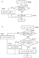
도 10은, 제1 실시예에 따른 화상 형성장치(1)가 슬립 상태(절전 상태)로 이행할 때의 처리를 설명하는 플로차트다. 이 처리를 실행하는 프로그램은, 이 프로그램 실행시에는 HDD(6)로부터 메모리(203)에 로드되고, 그 프로그램을 CPU(201)가 실행함으로써 처리가 실현된다.Fig. 10 is a flowchart for explaining the processing when the image forming apparatus 1 according to the first embodiment shifts to the sleep state (power saving state). The program for executing this processing is loaded from the
우선, 스텝 S1001에서, CPU(201)는, 절전 기능을 개시하는 타이밍이 되었는지 아닌지를 판정한다. 이 절전 기능을 개시하는 타이밍이란, 예를 들면, 오토매틱 슬립 타이머가 만료한 시점, 오토매틱 슬립 시각으로 된 시점, 오토매틱 셧다운 타이머가 만료한 시점, 오토매틱 셧다운 시각으로 된 시점 등이다. 여기에서, 절전 기능을 개시하는 타이밍으로 되었다고 판정되면, 제어가 스텝 S1002로 진행하여, CPU(201)는, 절전 기능의 개시를 표시하는 플래그(미도시)를 온으로 설정한다. 이 플래그는, 메모리(203)에 설치되어, 절전 기능을 개시하는 타이밍이 된 것을 표시한다.First, in step S1001, the
다음에, 제어가 스텝 S1003으로 진행하여, CPU(201)는, 실제로 절전 상태로 이행하기 위한 금지 조건이 충족되는지 아닌지를 판정한다. 이 금지 조건은, 예를 들면, 절전 기능을 개시하는 타이밍이 되었을 때에 인쇄 잡을 실행하고 있는 것 등이다. 이 금지 조건은, 실행 중인 인쇄 잡이 절전 기능에 의해 중단되면, 원하는 인쇄물이 얻어지지 않는다고 하는 문제가 생기는 것을 방지하기 위해서 설정되어 있다. 스텝 S1003에서 금지 조건이 충족되었다고 판정되면, CPU(201)는 스텝 S1003에서, 그 금지 조건이 충족되지 않았다고 판정될 때까지 기다리고, 즉 스텝 S1003에서 그 금지 조건이 충족되지 않았다고 판정된 후에는 제어가 스텝 S1004로 진행된다. 스텝 S1004에서, CPU(201)는, 절전 상태를 실행해서 화상 형성장치(1)를 슬립 상태로 이행한다.Next, the control proceeds to step S1003, and the
이와 같이 하여, 절전 기능을 개시하는 타이밍이 되고, 또한 화상 형성장치(1)가 절전 상태로 이행할 수 있는 상태이면, 화상 형성장치(1)는 슬립 상태(절전 상태)로 이행한다.In this way, the image forming apparatus 1 shifts to the sleep state (power saving state) when the timing at which the power saving function is started and the image forming apparatus 1 can transition to the power saving state.
도 11a 및 도 11b를 참조해서 제1 실시예에 있어서의 절전 기능을 실행할 때의 처리를 설명한다.The processing at the time of executing the power saving function in the first embodiment will be described with reference to Figs. 11A and 11B.
도 11a는, 도 10의 스텝 S1004에서 절전 기능을 실행할 때의 제1 실시예에 따른 처리를 설명하는 플로차트다.11A is a flowchart for explaining a process according to the first embodiment when executing the power saving function in step S1004 in Fig.
여기에서는, 스텝 S1101에서, CPU(201)는, 매뉴얼 스테이플러의 원고 삽입구의 센서가 원고를 검출했는지 아닌지를 판정한다. 원고를 검출했을 때는, 제어가 스텝 S1102로 진행하여, CPU(201)는, 절전 기능을 실행하지 않도록 한다. 이때, 전술한 스텝 S1002에서 설정한 플래그를 오프로 설정해도 된다는 점에 유념한다. 한편, 스텝 S1101에서 원고를 검출하지 않았을 때는, 처리가 스텝 S1103으로 진행하여, CPU(201)는, 절전 기능을 실행하도록 제어한다.Here, in step S1101, the
이에 따라, 매뉴얼 스테이플링 기능과 절전 기능을 동시에 유효하게 한 경우에도, 화상 형성장치(1)가 매뉴얼 스테이플링 실행 중에 절전 상태로 이행한다고 하는 문제를 해결할 수 있다. 즉, 매뉴얼 스테이플링 기능을 실행하고 있을 때는, 화상 형성장치(1)가 셧다운 조작, 슬립 타이머 등에 의해 절전 상태로 이행하는 조건이 충족된 것이 통지되어도, 화상 형성장치(1)가 매뉴얼 스테이플링용의 원고가 세트되어 있는 한, 절전 상태로 이행하는 일은 없다. 이때, 절전 상태로 이행하는 트리거(trigger)는, 전술한 것과 같이, 오토매틱 슬립 타이머, 오토매틱 슬립 시각, 오토매틱 셧다운 타이머, 오토매틱 셧다운 시각 등에 기인해서 발생한다.Accordingly, even when the manual stapling function and the power saving function are simultaneously enabled, it is possible to solve the problem that the image forming apparatus 1 shifts to the power saving state during execution of manual stapling. That is, when the manual stapling function is being executed, even if the image forming apparatus 1 is notified by the shutdown operation, the sleep timer, or the like that the condition for shifting to the power saving state is satisfied, the image forming apparatus 1 is not stapled for manual stapling As long as the document is set, there is no transition to the power saving state. At this time, a trigger for shifting to the power saving state occurs due to the automatic sleep timer, the automatic sleep time, the automatic shutdown timer, the automatic shutdown time, and the like, as described above.
[제2 실시예][Second Embodiment]
도 11b는, 도 10의 스텝 S1004에서 절전 기능을 실행할 때의 제2 실시예에 따른 처리를 설명하는 플로차트다. 이때, 제2 실시예에 따른 화상 형성장치(1)의 구성은 전술한 제1 실시예과 같기 때문에, 그 설명은 생략한다.Fig. 11B is a flowchart for explaining the processing according to the second embodiment when executing the power saving function in step S1004 in Fig. At this time, the configuration of the image forming apparatus 1 according to the second embodiment is the same as that of the first embodiment described above, and a description thereof will be omitted.
본 제2 실시예에서는, 절전 기능을 실행할 수 없는 금지 조건이 충족되기 때문에 절전 기능이 실행되지 않는 상태에서, 예를 들면, 오토매틱 슬립 타이머에 의해 절전 개시 시각이 된 것이 통지되어도, 절전 기능을 실행할 수 없는 경우의 처리를 설명한다.In the second embodiment, even if the automatic sleep timer is notified that the power saving start time has come, for example, in a state in which the power saving function is not executed because the prohibition condition in which the power saving function can not be executed is satisfied, The processing in the case where it can not be performed will be described.
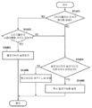
스텝 S1110에서, CPU(201)는 전술한 스텝 S1101과 마찬가지로, 매뉴얼 스테이플러의 원고 삽입구에 원고가 있는지 아닌지를 판정한다. 판정결과 원고가 있으면, 제어가 스텝 S1111로 진행하여, 절전 기능을 실행하지 않도록 한다. 한편, 스텝 S1110에서, 판정 결과 원고가 없으면, 제어가 스텝 S1112로 진행하여, CPU(201)는, 원고를 검출해서 절전 기능이 실행되지 않는 상태일 때에, 예를 들면, 셧다운 타이머나 슬립 타이머 등의 절전 기능의 개시 시각이 되었는지 아닌지를 판정한다. 판정 결과 원고가 있으면, 제어가 스텝 S1113로 진행하여, CPU(201)는, 그 개시 시각이 되었는데도 실행되지 않는 절전 기능을 즉시 실행하고, 이 처리를 종료한다. 이에 따라, 매뉴얼 스테이플러의 센서가 원고를 검출해서 절전 기능을 실행할 수 없는 상태일 때에, 셧다운 타이머나 슬립 타이머 등에 의거해서 절전 기능의 개시가 지시되었을 때, 즉시 절전 기능을 실행할 수 있다. 한편, 개시 시각이 되지 않았을 때는, 제어가 스텝 S1114로 진행하여, CPU(201)는, 통상의 절차에 따라 절전 기능을 실행한다.In step S1110, the
이와 같이, 본 제2 실시예에 따르면, 스테이플러(601)의 원고의 삽입구에 원고가 있는 경우에는, 스테이플러(601)의 절전 기능의 실행을 정지할 수 있다. 또한, 스테이플러(601)의 원고의 삽입구에 원고가 없을 경우에는, 삽입구에 원고가 있기 때문에, 실행되지 않은 절전 기능을 실행시킬 수 있다.As described above, according to the second embodiment, when there is a document at the insertion port of the document of the
[제3 실시예][Third Embodiment]
도 12a 및 도 12b를 참조해서 본 발명의 제3 실시예를 설명한다. 이때, 제3 실시예에 따른 화상 형성장치(1)의 구성은 전술한 제1 실시예와 같기 때문에, 그 설명을 생략한다.A third embodiment of the present invention will be described with reference to Figs. 12A and 12B. Since the configuration of the image forming apparatus 1 according to the third embodiment is the same as that of the first embodiment described above, the description thereof will be omitted.
본 제3 실시예는, 피니셔(100)의 전원이 온인 상태와, 피니셔(100)의 전원이 오프되어 있는 오프의 상태와, 피니셔(100)의 전원이 이들 상태의 중간 상태를 갖는 화상 형성장치를 지향한다. 화상 형성장치가 전원 온 상태로부터 전원 오프 상태로 이행하는 중간 상태일 때에, 유저가 매뉴얼 스테이플러(601)를 실행하려고 하면, 매뉴얼 스테이플러(601)의 실행중에 피니셔(100)의 전원이 꺼져 버린다.The third embodiment differs from the first embodiment in that the power supply of the
따라서, 이 문제를 해결하기 위해서, 제3 실시예에서는, 스테이플러(601)의 원고의 삽입구에 원고가 끼워져 있을 때는 스테이플러(601)의 전원이 오프되는 것을 지연시킨다.Therefore, in order to solve this problem, in the third embodiment, when the document is inserted into the insertion port of the document of the
도 12a는, 제3 실시예에 따른 화상 형성장치(1)의 처리를 설명하는 플로차트다.12A is a flowchart for explaining processing of the image forming apparatus 1 according to the third embodiment.
이 처리는, 셧다운 처리나 슬립 처리 등의 절전 처리에 의해, 스테이플러(601)를 전원 오프 상태로 천이하는 것에 의해 개시된다. 스텝 S1201에서, CPU(201)가 셧다운 처리를 개시하면, CPU(201)는 피니셔(100)의 스테이플러(601)의 원고의 삽입구에 원고가 있는지 없는지를 원고 검출 센서로 검출해서, 판정한다. 여기에서, 판정 결과 원고가 있으면, 제어가 스텝 S1202로 진행하여, CPU(201)는, 즉시 스테이플러(601)의 전원을 오프하지 않고, 대신에 전원의 오프를 예약하고 오프 처리를 종료한다. 한편, 스텝 S1201에서 판정 결과 원고가 없으면, 제어가 스텝 S1203으로 진행하여, CPU(201)는, 스테이플러(601)의 전원을 오프한다. 전원 오프가 예약되어 있는 경우에도, 즉시 전원을 오프한다.This process is started by shifting the
이와 같이, 제3 실시예에 따르면, 스테이플러(601)의 원고의 삽입구에 원고가 있는 경우에는, 스테이플러(601)의 절전 처리의 실행을 지연시킬 수 있다.As described above, according to the third embodiment, when there is a document at the insertion port of the document of the
[제4 실시예][Fourth Embodiment]
도 12b는, 제4 실시예에 따른 화상 형성장치(1)의 처리를 설명하는 플로차트다. 이때, 제4 실시예에 따른 화상 형성장치(1)의 구성은 전술한 제1 실시예와 같기 때문에, 그 구성 설명은 생략한다.12B is a flowchart for explaining the processing of the image forming apparatus 1 according to the fourth embodiment. Since the configuration of the image forming apparatus 1 according to the fourth embodiment is the same as that of the first embodiment described above, its description will be omitted.
제4 실시예는, 화상 형성장치(1)의 표시부(1500)가 오프일 때에, 매뉴얼 스테이플러를 셧다운하면, 유저는 아무것도 모르는 상태에서, 피니셔(100)를 갑자기 사용할 수 없게 된다고 하는 문제에 관한 것이다. 본 제4 실시예에서는, 표시부(1500)가 오프이고, 매뉴얼 스테이플러의 원고의 삽입구에서 원고가 검출된 상태에서, 셧다운 처리를 실행했을 때는, 표시부(1500)에 전력을 공급해서 표시부(1500)를 온으로 해서 유저에게 메시지를 표시한다. 이에 따라, 유저는, 그 표시부(1500)에 표시된 메시지에 의거해, 매뉴얼 스테이플러가 셧다운한 것을 인식할 수 있다.The fourth embodiment relates to a problem that if the manual stapler is shut down when the
스텝 S1210에서, CPU(201)는, 피니셔(100)의 스테이플러(601)의 원고의 삽입구에 원고가 있는지 아닌지를 판정하여, 판정 결과 원고가 없을 때는, 그대로 처리를 종료한다. 한편, 판정 결과 원고가 있을 때는, 제어가 스텝 S1211로 진행하여, CPU(201)는, 표시부(1500)의 백라이트가 오프인지 아닌지 판정한다. 판정 결과 오프가 아니면, 제어가 스텝 S1213으로 진행한다. 판정 결과 오프인 경우에는, 처리가 스텝 S1212로 진행하여, CPU(201)는, 표시부(1500)의 백라이트를 온으로 하고 스텝 S1213으로 진행한다. 스텝 S1213에서, CPU(201)는, 스테이플러(601)의 원고 삽입구로부터 원고를 제거하도록 유저에게 지시하는 메시지를 표시부(1500)에 표시하고, 이 처리를 종료한다.In step S1210, the
이상에서 설명한 것과 같이, 본 제4 실시예에 따르면, 매뉴얼 스테이플러의 셧다운을, 화상 형성장치의 유저에게 통지할 수 있다.As described above, according to the fourth embodiment, the shutdown of the manual stapler can be notified to the user of the image forming apparatus.
[제5 실시예][Fifth Embodiment]
도 13은, 제5 실시예에 따른 화상 형성장치(1)의 처리를 설명하는 플로차트다. 이때, 제5 실시예에 따른 화상 형성장치(1)의 구성은 전술한 제1 실시예와 같기 때문에, 그 구성 설명은 생략한다.13 is a flowchart for explaining the processing of the image forming apparatus 1 according to the fifth embodiment. Since the configuration of the image forming apparatus 1 according to the fifth embodiment is the same as that of the first embodiment described above, the description of the configuration is omitted.
본 제5 실시예는, 화상 형성장치(1)가 절전 상태일 때에, 유저가 매뉴얼 스테이플링을 행하기 위해서 스테이플러(601)의 원고 삽입구에 원고를 삽입해도, 스테이플할 수 없다는 문제에 관한 것이다.The fifth embodiment relates to a problem that staples can not be stapled even if a user inserts a document into the document insertion slot of the
CPU(201)는 화상 형성장치(1)가 슬립 상태로 이행하는 경우에 이 처리를 개시한다. 우선, 스텝 S1301에서, CPU(201)는, 절전 기능을 실행해서, 화상 형성장치(1)가 슬립 상태가 된다. 다음에, 제어가 스텝 1302로 진행하여, CPU(201)는, 피니셔(100)의 스테이플러(601)의 원고의 삽입구에 원고가 검출되었는지 아닌지를 판정한다. 전술한 바와 같이, 피니셔의 CPU(330)가 원고의 삽입구에서 원고를 검출했으면, CPU(330)는 원고의 존재를 CPLD(304)에 통지한다. 이에 따라, CPLD(304)는 신호 V_ON(307)에 의해 스위치 308을 온으로 해서, 제어부(3)에의 전력 공급을 개시해서 CPU(201)가 기동해, 원고의 존재를 인식한다. 스텝 S1302에서 CPU(201)가, 피니셔(100)의 스테이플러(601)의 원고의 삽입구에 원고가 존재한다는 것을 검출하면, 처리가 스텝 S1303으로 진행한다. 스텝 S1303에서, CPU(201)는 절전 상태로부터 복귀하고, 이 처리를 종료한다.The
즉, 스텝 S1303에서, 피니셔(100)의 CPU는, 스테이플러(601)의 센서에 의해 원고를 검출하면, 인터럽트 신호 INT_ACC(335)에 의해 CPLD(304)에 원고의 존재를 통지한다. 이에 따라, CPLD(304)는, IO 신호 V_ON(307)에 의해 릴레이 스위치 308을 온으로 해서, 제어부(3)에 전력을 공급해서, CPU(201)가 슬립 상태로부터 복귀한다.That is, in step S1303, when the CPU of the
제5 실시예에 따르면, 화상 형성장치(1)가 절전 상태일 때에, 스테이플러(601)를 사용하는 경우, 절절 상태로부터 복귀하기 위해 절전 키를 누르지 않아도, 스테이플러(601)에 원고를 세트하는 것만으로도 스테이플러(601)를 사용할 수 있게 된다.According to the fifth embodiment, in the case where the
[제6 실시예][Sixth Embodiment]
도 14는, 제6 실시예에 따른 화상 형성장치(1)의 처리를 설명하는 플로차트다. 이때, 제6 실시예에 따른 화상 형성장치(1)의 구성은 전술한 제1 실시예와 같기 때문에, 그 구성 설명은 생략한다.14 is a flowchart for explaining the processing of the image forming apparatus 1 according to the sixth embodiment. Since the configuration of the image forming apparatus 1 according to the sixth embodiment is the same as that of the first embodiment described above, its description will be omitted.
본 제6 실시예에서는, 스테이플러(601)가 스테이플을 가지고 있는 경우에는, 스테이플러(601)의 원고의 삽입구에서 원고가 검출되어도, 절전 기능을 실행한다. 예를 들면, 스테이플러(601)가 스테이플을 가지고 있지 않은 경우에, 슬립 상태로 이행하는 조건이 충족되면, 유저가 스테이플러(601)에서 스테이플을 설정할 때까지 화상 형성장치(1)가 슬립 상태로 이행한다.In the sixth embodiment, when the
우선, 스텝 S1401에서, CPU(201)는, 피니셔(100)의 스테이플러(601)의 원고 삽입구에 원고가 있는지 아닌지를 판정한다. 판정 결과 원고가 있을 때는, 제어가 스텝 S1402로 진행하여, CPU(201)는, 스테이플러(601)의 스테이플 구동부(822)에 스테이플이 있는지 아닌지를 판정한다. 판정 결과 스테이플이 있으면, 처리가 스텝 S1403으로 진행하여, CPU(201)는, 절전 기능의 실행을 금지하고, 이 처리를 종료한다. 이때, 절전 기능의 타이머 등은 정지하지 않는다.First, in step S1401, the
한편, 스텝 S1401에서, 원고가 없다고 판정했을 때, 또는 스텝 S1402에서 스테이플러(601)의 스테이플 구동부(822)에 스테이플이 없다고 판정하면, 제어가 스텝 S1404로 진행한다. 스텝 S1404에서, CPU(201)는, 도 11b의 스텝 S1112와 마찬가지로, 원고가 검출되어서 절전 기능이 실행되지 않은 상태일 때에, 절전 기능의 개시 시각이 되었는지 아닌지, 즉 셧다운 타이머나 슬립 타이머 등이 만료되었는지 아닌지를 판정한다. 판정 결과 개시 시각이 되었으면, 처리가 스텝 S1403으로 진행하여, CPU(201)는, 그 개시 시각에서 실행되지 않는 절전 기능을 즉시 실행한다. 한편, 개시 시각이 되지 않았을 때는, 처리가 스텝 S1406으로 진행하여, CPU(201)는, 통상의 절차에 따라 절전 기능을 실행한다.On the other hand, if it is determined in step S1401 that there is no document, or if it is determined in step S1402 that there is no staple in the
이상에서 설명한 것과 같이, 본 제6 실시예에 따르면, 피니셔(100)의 스테이플러(601)의 스테이플 구동부(822)에 스테이플이 없는 경우에는, 절전 기능을 정지하지 않도록 할 수 있다. 이에 따라, 스테이플러를 사용할 수 없는 데도 불구하고, 피니셔 처리에 의해 절전 기능을 실행할 수 없는 사태의 발생을 방지할 수 있다.As described above, according to the sixth embodiment, when there is no staple in the
[제7 실시예][Seventh Embodiment]
다음에, 본 발명의 제7 실시예를 설명한다. 본 제7 실시예에서는, 피니셔(100)가 별도의 전원을 가지고 있고, 그 자체에 대하여 매뉴얼 스테이플을 실행할 수 있으므로, 화상 형성장치(1)가 절전 상태로 이행할 수 있다.Next, a seventh embodiment of the present invention will be described. In the seventh embodiment, since the
구체적으로는, 절전 정지로부터 절전 개시까지의 절전 기능의 정지 중에, 절전 시간이 되는 경우에, 예를 들면, 셧다운이나 슬립 타이머가 만료되는 경우에는, 피니셔(100)가 별도의 전원을 가지고 있으면 즉시 절전 기능을 실행한다. 또한, 제7 실시예에서는, 제2 실시예와 마찬가지로, 절전 기능의 실행을 지연시킨다. 그러나, 절전 기능의 실행을 지연시키는 대신에, 제1 실시예와 마찬가지로, 절전 기능의 실행을 금지할 수도 있지만, 내용이 중복되기 때문에, 생략한다.Specifically, when the power saving time comes while the power saving function is stopped from the power saving stop to the power saving start, for example, when the shutdown or the sleep timer expires, if the
도 15는, 제7 실시예에 따른 화상 형성장치(1)의 전원 계통을 설명하는 블록도다. 이때, 전술한 도 6의 블록도와 공통되는 부분은 동일한 기호로 나타내고, 그들의 설명은 생략한다.15 is a block diagram for explaining a power supply system of the image forming apparatus 1 according to the seventh embodiment. At this time, the parts common to the blocks of Fig. 6 described above are denoted by the same symbols, and a description thereof will be omitted.
도 15에서는, 피니셔(100)의 전원 스위치(338)를 온하면, 전원(337)으로부터 전원선(339)을 통해서 피니셔(100)에 전력이 공급된다. 여기에서는, 전술한 제1 실시예와 달리, 전원(301)으로부터 피니셔(100)에 전력이 공급되지 않는다.15, power is supplied from the
도 16은, 제7 실시예에 따른 화상 형성장치(1)의 처리를 설명하는 플로차트다. 이때, 제7 실시예에 따른 화상 형성장치(1)의 구성은 전술한 제1 실시예과 같기 때문에, 그 설명은 생략한다.16 is a flowchart for explaining the processing of the image forming apparatus 1 according to the seventh embodiment. At this point, the configuration of the image forming apparatus 1 according to the seventh embodiment is the same as that of the first embodiment described above, and a description thereof will be omitted.
이 처리는, 유저에 의해 피니셔(100)의 스테이플러(601)의 원고 삽입구에 원고가 삽입된 것을 드라이버부(821)와 스테이플 구동부(822)의 원고 검출 센서가 검출하고, CPU(201)가 센서로부터 통지를 받는다. 우선, 스텝 S1601에서, CPU(201)는, 피니셔(100)의 스테이플러(601)의 원고의 삽입구에 원고가 있는지 아닌지를 판정한다. 판정 결과 원고가 있을 때는, 제어가 스텝 S1602로 진행하여, CPU(201)는, 피니셔(100)가 별도의 전원을 가지고 있는지 아닌지를 피니셔(100)에 문의해서 판정한다. 구체적으로는, CPU(201)는, 버스 콘트롤러 204와 224를 통해서 서브 보드(220)의 CPU(221)와 통신한다. 또한, CPU(201)는 화상 처리부(227), 디바이스 콘트롤러(226), 및 프린터부(4)의 CPU(320)을 통해서 피니셔(100)의 CPU(330)와 통신한다. 그리고나서, CPU(201)는, 피니셔(100)에 전원 스위치(338)가 있는지 없는지를 문의하고, 그것의 응답을 받음으로써, 피니셔(100)가 별도의 전원을 가지고 있는지 아닌지를 판정한다. 스텝 S1602에서, CPU(201)는, 피니셔(100)가 별도의 전원을 가지고 있지 않다고 판정했을 때는, 처리가 스텝 S1603으로 진행하고, CPU(201)는, 절전 기능의 실행을 금지하고, 이 처리를 종료한다. 이 경우에, 절전 기능의 타이머 등은 정지하지 않는다.This processing is carried out when the original detection sensor of the
한편, 스텝 S1601에서, CPU(201)가 원고가 존재하지 않는다고 판정한 경우, 또는 스텝 S1602에서, 피니셔(100)가 별도의 전원을 가지고 있다고 CPU(201)가 판정한 경우에는, 처리가 스텝 S1604로 진행하여, CPU(201)는, 도 11b의 S1112 등과 동일한 처리를 실행한다. 즉, CPU(201)는, 절전 기능의 실행을 금지하고나서 절전 기능을 개시할 때까지, 절전 기능 타이머가 만료되었는지 아닌지 혹은 절전 기능의 지정 시각이 되었는지 아닌지를 판정한다. 판정결과 지정 시각이 되었을 경우에는, 처리가 스텝 S1605로 진행한다. 스텝 S1605에서, CPU(201)는, 즉시 절전 기능을 실행해서 처리를 종료한다. 또한, 그렇지 않을 때는, 처리가 스텝 S1606으로 진행하여, CPU(201)는, 통상적으로 절전 기능을 실행해서 처리를 종료한다.On the other hand, if the
이상에서 설명한 것과 같이, 본 제7 실시예에 따르면, 화상 형성장치(1)와 피니셔(100)가 별도의 전원을 가지고 있는 경우에는, 화상 형성장치(1)가 슬립 상태로 이행해도, 피니셔에 영향을 미치지 않기 때문에, 화상 형성장치(1)는 즉시 절전 기능을 실행할 수 있다.As described above, according to the seventh embodiment, when the image forming apparatus 1 and the
[기타 실시예][Other Embodiments]
또한, 상기한 실시예에서는, 절전 상태로 이행하는 조건이 충족된 경우(S1003: Yes)에, 절전 기능을 실행한다. 그 절전 기능을 실행할 때에, 스테이플러의 센서가 원고를 검출했을 경우에는, 절전 기능의 실행을 금지하는 예를 설명하였다. 그렇지만, 상기 실시예에서는, 스테이플러의 센서가 원고를 검출하지 않았다고 하는 조건이, 절전 상태로 이행하는 조건이어도 된다. 즉, 스텝 S1003에 있어서, 스테이플러의 센서가 원고를 검출하지 않은 경우에(S1003: No), 스텝 S1004의 처리를 실행해도 된다.In the above-described embodiment, the power saving function is executed when the condition to shift to the power saving state is satisfied (S1003: Yes). The case where the execution of the power saving function is prohibited when the sensor of the stapler detects the document at the time of executing the power saving function has been described. However, in the above embodiment, the condition that the sensor of the stapler does not detect the original may be a condition to shift to the power saving state. That is, when the sensor of the stapler does not detect the original in step S1003 (S1003: No), the process of step S1004 may be executed.
본 발명의 추가 실시예(들)는, 상술한 실시 예(들) 중의 하나 또는 그 이상의 기능을 행하도록 기억매체(예를 들면, 비일시 컴퓨터 판독가능한 기억매체) 상에 기록된 컴퓨터 실행가능한 명령들을 판독 및 실행하는 시스템 또는 장치의 컴퓨터에 의해서 실현될 수 있고, 또 예를 들면, 상술한 실시예(들) 중의 하나 또는 그 이상의 기능을 행하도록 기억매체로부터 컴퓨터 실행가능한 명령들을 판독 및 실행함으로써 시스템 또는 장치의 컴퓨터에 의해 행해지는 방법에 의해서도 실현될 수 있다. 이 컴퓨터는 CPU(Central Processing Unit), MPU(Micro Processing Unit), 또는 다른 회로 중 하나 또는 그 이상을 구비할 수도 있고, 독립된 컴퓨터 또는 독립된 컴퓨터 프로세서의 네트워크를 포함할 수도 있다. 이 컴퓨터 실행가능한 명령들은 예를 들면, 네트워크 또는 기억매체로부터 컴퓨터에 제공될 수도 있다. 이 기억매체는 예를 들면, 하드 디스크, RAM(random-access memory), ROM(read only memory), 분산 컴퓨팅 시스템의 스토리지, 광디스크(컴팩트 디스크(CD), DVD(digital versatile disc), Blue-ray Disc(BD)TM 등), 플래시 메모리 디바이스, 메모리 카드 중 어느 하나 또는 그 이상을 포함할 수도 있다.Additional embodiments (s) of the present invention include computer executable instructions (e. G., Computer readable instructions) written on a storage medium (e. G., Non-temporary computer readable storage medium) to perform one or more of the above- For example, by reading and executing computer-executable instructions from a storage medium to perform one or more of the above-described embodiment (s), for example, But also by a method performed by a computer of the system or apparatus. The computer may comprise one or more of a central processing unit (CPU), a micro processing unit (MPU), or other circuitry, and may comprise a separate computer or a network of independent computer processors. These computer executable instructions may, for example, be provided to a computer from a network or storage medium. The storage medium may be, for example, a hard disk, a random-access memory (RAM), a read-only memory (ROM), a storage of a distributed computing system, an optical disk (compact disc (CD), a digital versatile disc Disc (BD) TM, etc.), a flash memory device, and a memory card.
본 발명은 예시적인 실시 예를 참조하면서 설명되었지만, 본 발명은 이 개시된 예시적인 실시 예에 한정되는 것이 아니라는 것이 이해될 것이다. 이하의 특허청구범위의 범주는 모든 변형 및 균등구조 및 기능을 포함하도록 가장 넓게 해석되어야 할 것이다. While the present invention has been described with reference to exemplary embodiments, it is to be understood that the invention is not limited to the disclosed exemplary embodiments. The scope of the following claims is to be accorded the broadest interpretation so as to encompass all such modifications and equivalent structures and functions.
1: 화상 형성장치 2: 스캐너부 3: 제어부 4: 프린터부 5: 조작부 6: 하드 디스크 7: FAX부 8: LAN 9: 컴퓨터(PC) 21: 원고 급지 유닛 41: 마킹 유닛 42: 급지 유닛 43 : 배지 유닛 100: 피니셔 301: 전원 303: 전원 제어부 302: 전원선 601: 스테이플러 700: 스택 트레이 821: 드라이버부 822: 스테이플 구동부 905: 추출 롤러 쌍 906: 전송 롤러 907: 급지 센서 908: 반송 패스 909:검출 센서부 910: 용지 검출 센서
1: Image forming apparatus 2: Scanner unit 3: Control unit 4: Printer unit 5: Operation unit 6: Hard disk 7: FAX unit 8: LAN 9: Computer 21: Original feed unit 41: Marking unit 42: : Stacker 700: stack tray 821: driver unit 822: staple driving unit 905: extraction roller pair 906: transfer roller 907: paper feed sensor 908: conveying path 909 : Detection sensor unit 910: paper detection sensor
Claims (19)
상기 화상 형성장치를 절전 상태로 이행시키는 전원 제어수단과,
제본처리가 행해지는 용지가 상기 피니셔에 유저에 의해서 세트된 것을 검출하면 상기 전원 제어수단에 의해 상기 화상 형성장치가 절전 상태로 이행하는 것을 금지하는 제어수단을 구비하는, 화상 형성장치.
An image forming apparatus to which a finisher is connected,
Power source control means for shifting the image forming apparatus to a power saving state,
And control means for prohibiting, by said power source control means, said image forming apparatus from transitioning to a power saving state when it is detected that a sheet on which bookbinding processing is performed is set by the user in said finisher.
상기 제어수단은, 상기 피니셔에 용지가 세트된 것을 검출하지 않는 경우에는 상기 전원 제어수단에 의해서 상기 화상 형성장치가 절전 상태로 이행하는 것을 허용하는, 화상 형성장치.
The method according to claim 1,
Wherein the control means allows the image forming apparatus to transition to a power saving state by the power source control means when the sheet finisher does not detect that the sheet is set.
상기 전원 제어수단은, 상기 피니셔에 용지가 세트된 것을 검출해서 절전 상태로의 이행을 금지하는 동안에 절전 기능을 개시하는 조건이 충족되었다고 판정된 경우에, 상기 피니셔에 설정된 용지가 더 이상 검출되지 않으면, 상기 화상 형성장치를 절전 상태로 이행시키는, 화상 형성장치.3. The method according to claim 1 or 2,
When the condition for starting the power saving function is determined to be satisfied while the power source control means detects that the paper has been set in the finisher and prohibits the transition to the power saving state, if the paper set in the finisher is no longer detected , And causes the image forming apparatus to transition to a power saving state.
상기 제어수단은, 상기 전원 제어수단에 의해서 상기 화상 형성장치가 절전 상태로 이행했을 때에 상기 피니셔에 용지가 세트된 것을 검출하면, 상기 전원 제어수단에 의해서 상기 화상 형성장치를 절전 상태로부터 복귀시키는, 화상 형성장치.
3. The method according to claim 1 or 2,
Wherein the control means controls the power source control means to return the image forming apparatus from the power saving state when the power source control means detects that the paper is set on the finisher when the image forming apparatus is in the power saving state, .
상기 전원 제어수단은, 상기 제본처리가 행해지는 용지가 상기 피니셔에 유저에 의해서 세트된 것을 검출한 경우에 표시수단의 백라이트를 온하는, 화상 형성장치.
3. The method according to claim 1 or 2,
Wherein the power source control means turns on the backlight of the display means when it is detected that the sheet on which the bookbinding processing is performed is set by the user on the finisher.
상기 제어수단은, 상기 제본처리가 행해지는 용지가 상기 피니셔에 유저에 의해서 세트된 것을 검출한 경우에, 또 상기 제본 처리에 사용되는 스테이플이 있는 경우에는, 상기 전원 제어수단에 의해서 상기 화상 형성장치를 절전 상태로 이행시키는 것을 금지하는, 화상 형성장치.
The method according to claim 1,
Wherein the control means controls the power supply control means to stop the image forming apparatus when the staple used in the bookbinding process is detected when it is detected that the sheet on which the bookbinding process is performed is set by the user on the finisher, To the power saving state.
상기 화상 형성장치와 상기 피니셔에 공통의 전원으로부터 전력이 공급되었는지 아닌지를 판정하는 판정수단을 더 구비하고,
상기 제어수단은, 상기 제본처리가 행해지는 용지가 상기 피니셔에 유저에 의해서 세트된 것을 검출한 경우에도, 상기 판정수단이 상기 화상 형성장치와 피니셔에 상이한 전원으로부터 전력이 공급되었다고 판정되면, 상기 전원 제어수단에 의해서 상기 화상 형성장치가 절전 상태로 이행하는 것을 허용하는, 화상 형성장치.
3. The method according to claim 1 or 2,
Further comprising determination means for determining whether power is supplied from a power source common to the image forming apparatus and the finisher,
Wherein the control unit is configured to control the image forming apparatus and the finisher so that when the determination unit determines that power is supplied from the power source different from the power source to the image forming apparatus and the finisher, And allows the image forming apparatus to transition to the power saving state by the control means.
상기 전원 제어수단은,
전원으로부터 제어부로의 전력 공급을 온/오프하도록 구성된 스위치와,
상기 스위치의 온/오프를 제어하는 신호를 출력하는 전원 감시수단을 구비하고,
상기 전원 감시수단에는, 절전 상태에서도 전력이 공급되는, 화상 형성장치.
3. The method according to claim 1 or 2,
Wherein the power source control means includes:
A switch configured to turn on / off power supply from the power source to the control unit,
And power supply monitoring means for outputting a signal for controlling on / off of the switch,
Wherein the power supply monitoring means is supplied with power even in a power saving state.
상기 피니셔는, 상기 용지가 세트된 것을 검출하도록 구성된 센서를 구비하고,
상기 전원 감시수단은, 상기 센서로부터의 신호에 의거하여 전력 공급을 제어하는, 화상 형성장치.
9. The method of claim 8,
Wherein the finisher has a sensor configured to detect that the paper is set,
Wherein the power supply monitoring means controls power supply based on a signal from the sensor.
상기 화상 형성장치를 절전 상태로 이행시키는 전원 제어단계와,
제본 처리가 행해지는 용지가 상기 피니셔에 유저에 의해서 세트된 것을 검출하면 상기 화상 형성장치가 절전 상태로 이행하는 것을 금지하는 제어단계를 포함하는, 제어방법.
A method of controlling an image forming apparatus connected to a finisher,
A power control step of causing the image forming apparatus to transition to a power saving state,
And prohibiting the image forming apparatus from transitioning to the power saving state if it is detected that the sheet subjected to bookbinding processing has been set by the user on the finisher.
상기 제어단계는, 상기 피니셔에 용지가 세트된 것을 검출하지 않은 경우에 상기 화상 형성장치가 절전 상태로 이행하는 것을 허용하는 것을 포함하는, 제어방법.
11. The method of claim 10,
Wherein said controlling step includes allowing the image forming apparatus to transition to a power saving state when it is not detected that the paper is set in the finisher.
상기 전원 제어단계는, 상기 피니셔에 용지가 세트된 것을 검출해서 절전 상태로의 이행을 금지하는 동안에 절전 기능을 개시하는 조건이 충족되었다고 판정된 경우에, 상기 피니셔에 설정된 용지가 더 이상 검출되지 않으면, 상기 화상 형성장치를 절전 상태로 이행시키는 것을 포함하는, 제어방법.
The method according to claim 10 or 11,
The power supply controlling step may be configured to perform the power supply control when the condition set for starting the power saving function is satisfied while detecting the setting of the sheet on the finisher and inhibiting the transition to the power saving state, , And causing the image forming apparatus to transition to a power saving state.
상기 전원 제어단계는, 상기 화상 형성장치가 절전 상태로 이행했을 때에 상기 피니셔에 용지가 세트된 것을 검출하면, 상기 화상 형성장치를 절전 상태로부터 복귀시키는 것을 포함하는, 제어방법.
The method according to claim 10 or 11,
Wherein the power supply controlling step includes returning the image forming apparatus from the power saving state when it detects that the paper is set on the finisher when the image forming apparatus has shifted to the power saving state.
상기 전원 제어단계는, 상기 제본처리가 행해지는 용지가 상기 피니셔에 유저에 의해서 세트된 것을 검출한 경우에, 표시수단의 백라이트를 온하는 것을 포함하는, 제어방법.
The method according to claim 10 or 11,
Wherein the power supply control step includes turning on the backlight of the display means when it is detected that the sheet on which the bookbinding processing is performed is set by the user in the finisher.
상기 제어단계는, 상기 제본처리가 행해지는 용지가 상기 피니셔에 유저에 의해서 세트된 것을 검출한 경우에, 또 상기 제본 처리에 사용되는 스테이플이 있는 경우에, 상기 화상 형성장치가 절전 상태로 이행하는 것을 금지하는 것을 포함하는, 제어방법.
11. The method of claim 10,
Wherein the control step includes a step of, when it is detected that the sheet on which the bookbinding process is performed is set by the user on the finisher, and when there is a staple used in the bookbinding process, the image forming apparatus shifts to the power- Lt; RTI ID = 0.0 > and / or < / RTI >
상기 화상 형성장치와 상기 피니셔에 공통의 전원으로부터 전력이 공급되는지 아닌지를 판정하는 판정단계를 더 포함하고,
상기 제어단계는, 상기 제본처리가 행해지는 용지가 상기 피니셔에 유저에 의해서 세트된 것을 검출한 경우에도, 상기 판정단계에서 상기 화상 형성장치와 피니셔에 상이한 전원으로부터 전력이 공급되었다고 판정되면, 상기 화상 형성장치가 절전 상태로 이행하는 것을 허용하는 것을 포함하는, 제어방법.
The method according to claim 10 or 11,
Further comprising a determining step of determining whether power is supplied from a power source common to the image forming apparatus and the finisher,
Wherein the control step includes a step of determining that the image forming apparatus and the finisher have been supplied with power from a different power source in the determination step even when the paper sheet on which the bookbinding processing is performed is detected as being set by the user on the finisher, Forming apparatus to transition to a power saving state.
상기 화상 형성장치는,
전원으로부터 제어부로의 전력 공급을 온/오프하도록 구성된 스위치와,
상기 스위치의 온/오프를 제어하는 신호를 출력하는 전원 감시수단을 구비하고,
상기 전원 제어단계는, 절전 상태에서도 상기 전원 감시수단에 전력을 공급하는 것을 포함하는, 제어방법.
The method according to claim 10 or 11,
The image forming apparatus comprising:
A switch configured to turn on / off power supply from the power source to the control unit,
And power supply monitoring means for outputting a signal for controlling on / off of the switch,
Wherein the power supply control step includes supplying power to the power supply monitoring means even in a power saving state.
상기 피니셔는, 상기 용지가 세트된 것을 검출하도록 구성된 센서를 포함하고,
상기 전원 감시단계는, 상기 센서로부터의 신호에 의거하여 상기 전원 감시수단이 전력 공급을 제어하는 것을 포함하는, 제어방법.
18. The method of claim 17,
Wherein the finisher includes a sensor configured to detect that the sheet is set,
And the power monitoring step includes controlling the power supply monitoring means based on a signal from the sensor.
Applications Claiming Priority (2)
| Application Number | Priority Date | Filing Date | Title |
|---|---|---|---|
| JP2014096220A JP6381275B2 (en) | 2014-05-07 | 2014-05-07 | Image forming apparatus, control method thereof, and program |
| JPJP-P-2014-096220 | 2014-05-07 |
Related Parent Applications (1)
| Application Number | Title | Priority Date | Filing Date |
|---|---|---|---|
| KR1020150062878A Division KR20150127544A (en) | 2014-05-07 | 2015-05-06 | Image forming apparatus and method for controlling same, and program |
Publications (2)
| Publication Number | Publication Date |
|---|---|
| KR20180098497A true KR20180098497A (en) | 2018-09-04 |
| KR102183757B1 KR102183757B1 (en) | 2020-11-27 |
Family
ID=53177056
Family Applications (2)
| Application Number | Title | Priority Date | Filing Date |
|---|---|---|---|
| KR1020150062878A Ceased KR20150127544A (en) | 2014-05-07 | 2015-05-06 | Image forming apparatus and method for controlling same, and program |
| KR1020180098508A Active KR102183757B1 (en) | 2014-05-07 | 2018-08-23 | Image forming system, image forming apparatus and method for controlling therof |
Family Applications Before (1)
| Application Number | Title | Priority Date | Filing Date |
|---|---|---|---|
| KR1020150062878A Ceased KR20150127544A (en) | 2014-05-07 | 2015-05-06 | Image forming apparatus and method for controlling same, and program |
Country Status (5)
| Country | Link |
|---|---|
| US (5) | US9454121B2 (en) |
| EP (2) | EP2942669B1 (en) |
| JP (1) | JP6381275B2 (en) |
| KR (2) | KR20150127544A (en) |
| CN (2) | CN105100530B (en) |
Families Citing this family (11)
| Publication number | Priority date | Publication date | Assignee | Title |
|---|---|---|---|---|
| JP6769765B2 (en) * | 2016-07-19 | 2020-10-14 | シャープ株式会社 | Image forming device, control program and control method |
| JP6669021B2 (en) | 2016-09-13 | 2020-03-18 | 京セラドキュメントソリューションズ株式会社 | Image forming device |
| JP6833491B2 (en) * | 2016-12-12 | 2021-02-24 | キヤノン株式会社 | Information processing device |
| JP7309342B2 (en) * | 2018-10-26 | 2023-07-18 | キヤノン株式会社 | image forming device |
| JP7254491B2 (en) * | 2018-11-29 | 2023-04-10 | キヤノン株式会社 | image forming system |
| JP7215250B2 (en) * | 2019-03-12 | 2023-01-31 | コニカミノルタ株式会社 | image forming device |
| JP7296911B2 (en) | 2019-04-11 | 2023-06-23 | キヤノン株式会社 | Image forming apparatus and its control method |
| KR20210026068A (en) * | 2019-08-29 | 2021-03-10 | 휴렛-팩커드 디벨롭먼트 컴퍼니, 엘.피. | Switch from sleep mode to manual stapling operation mode |
| JP7334591B2 (en) * | 2019-11-25 | 2023-08-29 | コニカミノルタ株式会社 | image forming system |
| CN112721433B (en) * | 2020-12-03 | 2022-06-14 | 东莞全艺印务科技有限公司 | A printing press with easy delivery and automatic alignment |
| JP7728690B2 (en) | 2021-12-07 | 2025-08-25 | シャープ株式会社 | Image forming apparatus and power saving control method thereof |
Citations (2)
| Publication number | Priority date | Publication date | Assignee | Title |
|---|---|---|---|---|
| JP2005246870A (en) * | 2004-03-05 | 2005-09-15 | Canon Inc | Image forming system and control method thereof |
| JP2012179895A (en) * | 2011-02-08 | 2012-09-20 | Canon Inc | Printing apparatus, control method therefor, and program |
Family Cites Families (33)
| Publication number | Priority date | Publication date | Assignee | Title |
|---|---|---|---|---|
| US4917366A (en) * | 1986-02-25 | 1990-04-17 | Canon Kabushiki Kaisha | Sheet handling apparatus |
| JPS6351278A (en) | 1986-08-21 | 1988-03-04 | Minolta Camera Co Ltd | Sorter equipped with finisher |
| JP2000086072A (en) * | 1998-09-11 | 2000-03-28 | Canon Inc | Sheet stacking apparatus and image forming apparatus having the same |
| JP2000206831A (en) | 1999-01-11 | 2000-07-28 | Ricoh Co Ltd | Image forming apparatus with post-processing device |
| JP2003015479A (en) * | 2001-06-29 | 2003-01-17 | Ricoh Co Ltd | Image forming device |
| US6948224B2 (en) * | 2003-05-02 | 2005-09-27 | Gradco (Japan) Ltd | Automatic stapling method and stapler |
| JP4287232B2 (en) * | 2003-09-30 | 2009-07-01 | 京セラミタ株式会社 | Stapling apparatus and image forming apparatus |
| JP3943069B2 (en) | 2003-09-30 | 2007-07-11 | 京セラミタ株式会社 | Paper post-processing apparatus and image forming apparatus |
| JP4371840B2 (en) | 2004-02-06 | 2009-11-25 | キヤノン株式会社 | Sheet processing apparatus and image forming apparatus |
| JP4366272B2 (en) * | 2004-08-05 | 2009-11-18 | キヤノン株式会社 | Image forming apparatus, control method, and image forming system |
| JP4533285B2 (en) * | 2005-08-30 | 2010-09-01 | キヤノン株式会社 | Image forming system and power saving control method |
| JP2007225771A (en) | 2006-02-22 | 2007-09-06 | Canon Inc | Image forming apparatus |
| JP4569522B2 (en) * | 2006-05-30 | 2010-10-27 | コニカミノルタビジネステクノロジーズ株式会社 | Image forming system |
| JP5064061B2 (en) * | 2007-02-28 | 2012-10-31 | 京セラドキュメントソリューションズ株式会社 | Image forming apparatus and program |
| US7845626B2 (en) * | 2007-06-13 | 2010-12-07 | Kabushiki Kaisha Toshiba | Sheet processing apparatus and sheet processing method |
| JP5473321B2 (en) * | 2008-12-27 | 2014-04-16 | キヤノン株式会社 | Image forming apparatus and image forming apparatus control method |
| JP5435968B2 (en) * | 2009-01-20 | 2014-03-05 | キヤノン株式会社 | Sheet processing apparatus, sheet processing apparatus control method, storage medium, and program |
| US20110033218A1 (en) * | 2009-08-04 | 2011-02-10 | Kabushiki Kaisha Toshiba | Stapling apparatus, finishing apparatus, and stapling method |
| CN102190195A (en) * | 2010-03-05 | 2011-09-21 | 株式会社东芝 | Sheet finishing apparatus and image forming apparatus |
| JP5565138B2 (en) * | 2010-06-28 | 2014-08-06 | 株式会社リコー | Control method of sheet folding apparatus |
| KR101755225B1 (en) * | 2010-11-23 | 2017-07-07 | 에스프린팅솔루션 주식회사 | Image forming apparatus and power control method thereof |
| JP5531005B2 (en) * | 2011-12-26 | 2014-06-25 | 株式会社沖データ | Electronics |
| TWI441741B (en) * | 2012-03-09 | 2014-06-21 | Primax Electronics Ltd | Stapling device of printing device |
| JP5870795B2 (en) | 2012-03-21 | 2016-03-01 | 富士ゼロックス株式会社 | Moving body detection device, power supply control device, image processing device |
| JP5932518B2 (en) * | 2012-06-26 | 2016-06-08 | キヤノン株式会社 | Image forming apparatus, image forming apparatus control method, program, and image forming system |
| JP2014108831A (en) * | 2012-11-30 | 2014-06-12 | Canon Inc | Printing system, printing system control method, and program |
| JP6087607B2 (en) * | 2012-12-07 | 2017-03-01 | キヤノン株式会社 | Printing apparatus, control method thereof, and program |
| JP6080608B2 (en) * | 2013-02-25 | 2017-02-15 | キヤノン株式会社 | Image forming apparatus, sheet post-processing apparatus, and control method |
| JP6202878B2 (en) * | 2013-05-09 | 2017-09-27 | キヤノン株式会社 | Sheet material binding apparatus and image forming system |
| JP2014238542A (en) * | 2013-06-10 | 2014-12-18 | キヤノン株式会社 | Printer, control method thereof, and program |
| JP6218447B2 (en) * | 2013-06-14 | 2017-10-25 | キヤノン株式会社 | Image forming apparatus, control method thereof, and program |
| JP6192376B2 (en) * | 2013-06-18 | 2017-09-06 | キヤノン株式会社 | Printing apparatus, printing apparatus control method, and program |
| JP6141128B2 (en) * | 2013-07-11 | 2017-06-07 | キヤノンファインテック株式会社 | Sheet bundle binding processing apparatus and image forming system using the same |
-
2014
- 2014-05-07 JP JP2014096220A patent/JP6381275B2/en active Active
-
2015
- 2015-04-24 EP EP15001219.3A patent/EP2942669B1/en active Active
- 2015-04-24 EP EP18201599.0A patent/EP3462242B1/en active Active
- 2015-04-24 US US14/695,523 patent/US9454121B2/en active Active
- 2015-05-05 CN CN201510223747.8A patent/CN105100530B/en active Active
- 2015-05-05 CN CN201910531706.3A patent/CN110266905B/en not_active Expired - Fee Related
- 2015-05-06 KR KR1020150062878A patent/KR20150127544A/en not_active Ceased
-
2016
- 2016-09-09 US US15/260,776 patent/US10067455B2/en active Active
-
2018
- 2018-07-31 US US16/050,267 patent/US10527997B2/en active Active
- 2018-08-23 KR KR1020180098508A patent/KR102183757B1/en active Active
-
2019
- 2019-11-20 US US16/689,273 patent/US10948865B2/en active Active
-
2021
- 2021-01-29 US US17/162,156 patent/US11320775B2/en active Active
Patent Citations (2)
| Publication number | Priority date | Publication date | Assignee | Title |
|---|---|---|---|---|
| JP2005246870A (en) * | 2004-03-05 | 2005-09-15 | Canon Inc | Image forming system and control method thereof |
| JP2012179895A (en) * | 2011-02-08 | 2012-09-20 | Canon Inc | Printing apparatus, control method therefor, and program |
Also Published As
| Publication number | Publication date |
|---|---|
| CN105100530B (en) | 2019-06-28 |
| CN105100530A (en) | 2015-11-25 |
| EP3462242B1 (en) | 2024-10-09 |
| US20160378046A1 (en) | 2016-12-29 |
| US20200089154A1 (en) | 2020-03-19 |
| KR102183757B1 (en) | 2020-11-27 |
| US9454121B2 (en) | 2016-09-27 |
| US10527997B2 (en) | 2020-01-07 |
| JP2015214034A (en) | 2015-12-03 |
| EP2942669A1 (en) | 2015-11-11 |
| CN110266905A (en) | 2019-09-20 |
| JP6381275B2 (en) | 2018-08-29 |
| US20150323894A1 (en) | 2015-11-12 |
| US10067455B2 (en) | 2018-09-04 |
| US10948865B2 (en) | 2021-03-16 |
| EP2942669B1 (en) | 2018-11-28 |
| CN110266905B (en) | 2021-09-21 |
| US20180335743A1 (en) | 2018-11-22 |
| EP3462242A1 (en) | 2019-04-03 |
| US20210149332A1 (en) | 2021-05-20 |
| KR20150127544A (en) | 2015-11-17 |
| US11320775B2 (en) | 2022-05-03 |
Similar Documents
| Publication | Publication Date | Title |
|---|---|---|
| KR102183757B1 (en) | Image forming system, image forming apparatus and method for controlling therof | |
| US12034896B2 (en) | Printing system, printing system control method, and storage medium | |
| US9223275B2 (en) | Image forming apparatus, method for controlling image forming apparatus, and storage medium storing program | |
| US8947691B2 (en) | Printing apparatus, method for controlling the same, and storage medium | |
| JP7296911B2 (en) | Image forming apparatus and its control method | |
| US7590362B2 (en) | Image forming apparatus for communicating with sheet processing apparatus for executing post-process to sheet | |
| JP6516913B2 (en) | Image forming system and image forming apparatus | |
| KR101972752B1 (en) | Sheet processing apparatus, method for controlling sheet processing apparatus, program and storage medium | |
| JP6431638B2 (en) | Apparatus and control method thereof, image forming apparatus and control method thereof, and image forming system | |
| JP2015100935A (en) | Printing apparatus, control method therefor, and program | |
| JP6685447B2 (en) | Image forming apparatus and control method thereof | |
| US20170043973A1 (en) | Post-processing apparatus, post-processing method and image forming apparatus | |
| JP2015101064A (en) | Image forming system control method and program |
Legal Events
| Date | Code | Title | Description |
|---|---|---|---|
| A107 | Divisional application of patent | ||
| PA0107 | Divisional application |
Comment text: Divisional Application of Patent Patent event date: 20180823 Patent event code: PA01071R01D Filing date: 20150506 Application number text: 1020150062878 |
|
| PG1501 | Laying open of application | ||
| A201 | Request for examination | ||
| PA0201 | Request for examination |
Patent event code: PA02012R01D Patent event date: 20181012 Comment text: Request for Examination of Application Patent event code: PA02011R04I Patent event date: 20180823 Comment text: Divisional Application of Patent |
|
| E902 | Notification of reason for refusal | ||
| PE0902 | Notice of grounds for rejection |
Comment text: Notification of reason for refusal Patent event date: 20190102 Patent event code: PE09021S01D |
|
| E902 | Notification of reason for refusal | ||
| PE0902 | Notice of grounds for rejection |
Comment text: Notification of reason for refusal Patent event date: 20190829 Patent event code: PE09021S01D |
|
| E90F | Notification of reason for final refusal | ||
| PE0902 | Notice of grounds for rejection |
Comment text: Final Notice of Reason for Refusal Patent event date: 20200313 Patent event code: PE09021S02D |
|
| E701 | Decision to grant or registration of patent right | ||
| PE0701 | Decision of registration |
Patent event code: PE07011S01D Comment text: Decision to Grant Registration Patent event date: 20200821 |
|
| GRNT | Written decision to grant | ||
| PR0701 | Registration of establishment |
Comment text: Registration of Establishment Patent event date: 20201123 Patent event code: PR07011E01D |
|
| PR1002 | Payment of registration fee |
Payment date: 20201124 End annual number: 3 Start annual number: 1 |
|
| PG1601 | Publication of registration | ||
| PR1001 | Payment of annual fee |
Payment date: 20231023 Start annual number: 4 End annual number: 4 |
|
| PR1001 | Payment of annual fee |
Payment date: 20241029 Start annual number: 5 End annual number: 5 |