KR20180098463A - Auto focussing apparatus for zoom lens - Google Patents
Auto focussing apparatus for zoom lens Download PDFInfo
- Publication number
- KR20180098463A KR20180098463A KR1020170025137A KR20170025137A KR20180098463A KR 20180098463 A KR20180098463 A KR 20180098463A KR 1020170025137 A KR1020170025137 A KR 1020170025137A KR 20170025137 A KR20170025137 A KR 20170025137A KR 20180098463 A KR20180098463 A KR 20180098463A
- Authority
- KR
- South Korea
- Prior art keywords
- groove
- optical axis
- zoom lens
- axis direction
- ball
- Prior art date
- Legal status (The legal status is an assumption and is not a legal conclusion. Google has not performed a legal analysis and makes no representation as to the accuracy of the status listed.)
- Granted
Links
Images


Classifications
-
- G—PHYSICS
- G02—OPTICS
- G02B—OPTICAL ELEMENTS, SYSTEMS OR APPARATUS
- G02B27/00—Optical systems or apparatus not provided for by any of the groups G02B1/00 - G02B26/00, G02B30/00
- G02B27/64—Imaging systems using optical elements for stabilisation of the lateral and angular position of the image
- G02B27/646—Imaging systems using optical elements for stabilisation of the lateral and angular position of the image compensating for small deviations, e.g. due to vibration or shake
-
- G—PHYSICS
- G02—OPTICS
- G02B—OPTICAL ELEMENTS, SYSTEMS OR APPARATUS
- G02B7/00—Mountings, adjusting means, or light-tight connections, for optical elements
- G02B7/02—Mountings, adjusting means, or light-tight connections, for optical elements for lenses
- G02B7/04—Mountings, adjusting means, or light-tight connections, for optical elements for lenses with mechanism for focusing or varying magnification
- G02B7/10—Mountings, adjusting means, or light-tight connections, for optical elements for lenses with mechanism for focusing or varying magnification by relative axial movement of several lenses, e.g. of varifocal objective lens
-
- G—PHYSICS
- G03—PHOTOGRAPHY; CINEMATOGRAPHY; ANALOGOUS TECHNIQUES USING WAVES OTHER THAN OPTICAL WAVES; ELECTROGRAPHY; HOLOGRAPHY
- G03B—APPARATUS OR ARRANGEMENTS FOR TAKING PHOTOGRAPHS OR FOR PROJECTING OR VIEWING THEM; APPARATUS OR ARRANGEMENTS EMPLOYING ANALOGOUS TECHNIQUES USING WAVES OTHER THAN OPTICAL WAVES; ACCESSORIES THEREFOR
- G03B3/00—Focusing arrangements of general interest for cameras, projectors or printers
- G03B3/10—Power-operated focusing
-
- G—PHYSICS
- G03—PHOTOGRAPHY; CINEMATOGRAPHY; ANALOGOUS TECHNIQUES USING WAVES OTHER THAN OPTICAL WAVES; ELECTROGRAPHY; HOLOGRAPHY
- G03B—APPARATUS OR ARRANGEMENTS FOR TAKING PHOTOGRAPHS OR FOR PROJECTING OR VIEWING THEM; APPARATUS OR ARRANGEMENTS EMPLOYING ANALOGOUS TECHNIQUES USING WAVES OTHER THAN OPTICAL WAVES; ACCESSORIES THEREFOR
- G03B2205/00—Adjustment of optical system relative to image or object surface other than for focusing
- G03B2205/0053—Driving means for the movement of one or more optical element
- G03B2205/0069—Driving means for the movement of one or more optical element using electromagnetic actuators, e.g. voice coils
Landscapes
- Physics & Mathematics (AREA)
- General Physics & Mathematics (AREA)
- Optics & Photonics (AREA)
- Lens Barrels (AREA)
Abstract
본 발명에 의한 줌렌즈용 자동초점 조절장치는, 상호 이격되게 위치되는 제1 및 제2가이드레일과, 상기 제1 및 제2가이드레일 각각의 끝단에 구비되는 제1 및 제2볼받침부를 포함하는 베이스프레임; 상기 제1 및 제2가이드레일 각각에 대응되도록 배치되는 제1 및 제2홈부레일이 구비되고, 광축 방향으로 선형 이동하는 줌렌즈캐리어; 상기 줌렌즈캐리어를 상기 광축 방향으로 선형 이동시키는 구동부; 및 상기 제1홈부레일과 제1가이드레일 사이 및 상기 제2홈부레일과 제2가이드레일 사이에 배치되며 상기 제1 및 제2볼 받침부에 의하여 외부 이탈이 방지되는 복수개의 볼을 포함하는 것을 특징으로 한다.The automatic focusing device for a zoom lens according to the present invention includes first and second guide rails spaced apart from each other and first and second ball receivers provided at the ends of the first and second guide rails, A base frame; A zoom lens carrier having first and second groove bores arranged to correspond to the first and second guide rails, respectively, and linearly moving in the optical axis direction; A driving unit for linearly moving the zoom lens carrier in the optical axis direction; And a plurality of balls disposed between the first groove guide and the first guide rail and between the second groove guide and the second guide rail and prevented from being detached by the first and second ball support portions .
Description
본 발명은 자동초점 조절장치에 관한 것으로서, 더욱 구체적으로는 저전력 환경의 구현 및 선형 이동의 정밀성을 향상시키는 구조가 적용된 줌렌즈용 자동초점 조절장치에 관한 것이다. The present invention relates to an autofocusing apparatus, and more particularly, to an autofocusing apparatus for a zoom lens to which a structure for improving the precision of linear movement and realization of a low-power environment is applied.
하드웨어 기술의 발전, 사용자 환경 등의 변화에 따라 스마트폰 등의 휴대 단말기(모바일 단말기)에는 통신을 위한 기본적인 기능 이외에 다양하고 복합적인 기능이 통합적으로 구현되고 있다. In accordance with the development of hardware technology, user environment, etc., various and complex functions other than basic functions for communication are integrally implemented in portable terminals (mobile terminals) such as smart phones.
그 대표적인 예로 오토포커스(AF, Auto Focus), 손떨림 보정(OIS, Optical Image Stabilization) 등의 기능이 구현된 카메라 모듈을 들 수 있으며, 근래에는 인증이나 보안 등을 위한 음성 인식, 지문 인식, 홍채 인식 기능 등도 휴대 단말기에 탑재되고 있다. 또한 최근에는 초점 거리를 다양하게 가변적으로 조정할 수 있도록 복수 개 렌즈 그룹이 집합되어 있는 줌렌즈의 장착도 시도되고 있다.Examples of the camera module include a camera module implemented with functions such as autofocus (AF), optical image stabilization (OIS), and the like. In recent years, there has been proposed a camera module for voice recognition, fingerprint recognition, Functions and the like are also being installed in mobile terminals. In recent years, attempts have also been made to mount a zoom lens in which a plurality of lens groups are assembled so that the focal length can be variably adjusted in various ways.
줌렌즈의 경우, 일반 렌즈와는 달리 광이 유입되는 방향인 광축 방향으로 복수 개 렌즈 또는 렌즈군들이 동축에 배열되는 구조를 가지고 있으므로 일반 렌즈보다 광축 방향으로 그 길이가 상당히 연장된다는 특성을 가진다. Unlike a general lens, the zoom lens has a structure in which a plurality of lenses or groups of lenses are arranged coaxially in the direction of an optical axis in which light is introduced, so that the length of the lens is significantly extended in the direction of the optical axis.
줌렌즈를 통과한 피사체의 광(Light)은 다른 렌즈와 같이 CCD(Charged-coupled Device), CMOS(Complementary Metal-oxide Semiconductor)와 같은 촬상소자로 유입된 후 후속 프로세싱을 통하여 이미지 데이터로 생성된다.Light of a subject passing through the zoom lens is introduced into an image pickup device such as a CCD (Charge-coupled Device) or CMOS (Complementary Metal-Oxide Semiconductor) like other lenses and is then generated as image data through subsequent processing.
줌 렌즈가 다른 일반 렌즈와 같이 휴대 단말의 메인 기판에서 입설(立設)되는 방향 즉, 메인 기판에서 수직한 방향으로 설치되는 경우 휴대 단말에는 줌 렌즈의 높이(광축 방향 길이)만큼의 공간이 확보되어야 하므로 휴대 단말이 지향하는 장치 소형과 경량화의 본질적 특성에 최적화되기 어렵다는 문제가 있다. When the zoom lens is installed in a direction perpendicular to the main board, that is, in a direction perpendicular to the main board of the portable terminal, such as another general lens, the portable terminal is provided with a space corresponding to the height of the zoom lens There is a problem that it is difficult to optimize the essential features of the compact and lightweight device that the portable terminal is aimed at.
종래 이러한 문제를 해결하기 위하여 렌즈의 각도, 크기, 이격된 간격, 초점 거리 등을 조정하여 광학계 자체의 크기를 축소시키는 방법이 있으나, 이러한 방법은 줌 렌즈 내지 줌렌즈 배럴의 크기를 물리적으로 줄이는 방법이므로 본질적인 한계가 있음은 물론, 줌 렌즈의 본질적인 특성을 저하시킬 수 있다는 문제점을 가진다. In order to solve such a problem, there is a method of reducing the size of the optical system itself by adjusting the angle, size, spaced distance, focal distance, and the like of the lens, but this method is a method of physically reducing the size of the zoom lens or zoom lens barrel There is an inherent limitation, and there is a problem that the intrinsic characteristics of the zoom lens can be deteriorated.
또한 자동초점기능(AF, Auto Focus)을 구현하는 경우 줌렌즈의 광축 방향 길이가 길어지고 자체 무게가 무거워짐에 따라 줌렌즈가 탑재된 배럴 내지 캐리어(프레임)의 선형 이동이 정밀하게 이루어지지 않고, 틸트 등의 불량이 발생하여 자동초점기능 자체의 성능이 저하되는 문제가 발생될 수 있다.In addition, when the auto focus function (AF, Auto Focus) is implemented, since the length of the zoom lens in the optical axis direction becomes long and its own weight becomes heavy, linear movement of the barrel or carrier (frame) on which the zoom lens is mounted is not precisely performed, And the performance of the auto focus function itself may be deteriorated.
또한, 줌렌즈가 탑재된 캐리어의 광축 방향 선형이동이 볼에 의하여 지지되는 구조도 개시되어 있는데, 캐리어의 길이가 길어진 만큼 다소 많은 볼에 의하여 캐리어가 지지되어야 하고 캐리어가 선형 이동함에 따라 지지되는 볼 또한, 함께 이동시키는 구조로 이루어져 있어 캐리어를 선형 이동시키는 구동력이 커진다는 문제점이 있다. Also disclosed is a structure in which a linear movement in the direction of the optical axis of the carrier on which the zoom lens is mounted is supported by the ball. As the length of the carrier is long, the carrier must be supported by a relatively large number of balls, And there is a problem that the driving force for moving the carrier linearly increases.
본 발명은 상기와 같은 배경에서 상술된 문제점을 해결하기 위하여 창안된 것으로서, 줌렌즈가 탑재되는 줌렌즈캐리어를 틸트 발생없이 저전력으로 선형 이동시킴으로써 줌렌즈의 자동 초점 기능을 최적화시킬 수 있는 줌렌즈용 자동초점 조절장치를 제공하는데 그 목적이 있다.SUMMARY OF THE INVENTION The present invention has been made in view of the above problems, and it is an object of the present invention to provide an automatic focusing device for a zoom lens capable of optimizing an auto-focus function of a zoom lens by linearly moving a zoom lens carrier on which a zoom lens is mounted, The purpose is to provide.
본 발명의 다른 목적 및 장점들은 아래의 설명에 의하여 이해될 수 있으며, 본 발명의 실시예에 의하여 보다 분명하게 알게 될 것이다. 또한 본 발명의 목적 및 장점들은 특허청구범위에 나타난 구성과 그 구성의 조합에 의하여 실현될 수 있다.Other objects and advantages of the present invention will become apparent from the following description, and it will be apparent from the description of the embodiments of the present invention. Further, the objects and advantages of the present invention can be realized by a combination of the constitution shown in the claims and the constitution thereof.
상기 목적을 달성하기 위한 본 발명의 줌렌즈용 자동초점 조절장치는, 상호 이격되게 위치되는 제1 및 제2가이드레일과, 상기 제1 및 제2가이드레일 각각의 끝단에 구비되는 제1 및 제2볼받침부를 포함하는 베이스프레임; 상기 제1 및 제2가이드레일 각각에 대응되도록 배치되는 제1 및 제2홈부레일이 구비되고, 광축 방향으로 선형 이동하는 줌렌즈캐리어; 상기 줌렌즈캐리어를 상기 광축 방향으로 선형 이동시키는 구동부; 및 상기 제1홈부레일과 제1가이드레일 사이 및 상기 제2홈부레일과 제2가이드레일 사이에 배치되며 상기 제1 및 제2볼 받침부에 의하여 외부 이탈이 방지되는 복수개의 볼을 포함하여 구성될 수 있다.According to an aspect of the present invention, there is provided an automatic focusing device for a zoom lens comprising first and second guide rails spaced apart from each other, first and second guide rails provided at the ends of the first and second guide rails, A base frame including a ball receiving portion; A zoom lens carrier having first and second groove bores arranged to correspond to the first and second guide rails, respectively, and linearly moving in the optical axis direction; A driving unit for linearly moving the zoom lens carrier in the optical axis direction; And a plurality of balls disposed between the first groove guide and the first guide rail and between the second groove guide and the second guide rail and prevented from being detached by the first and second ball bearings, .
또한, 본 발명의 상기 제1 및 제2홈부레일은 상기 볼이 상기 광축 방향을 기준으로 상부 방향으로 이동하는 것을 방지하는 볼스토퍼가 각각 구비될 수 있으며, 본 발명의 제1 및 제2홈부레일 중 하나 이상은, 상기 광축 방향을 기준으로 하부 끝단이 개방된 형태로 이루어지는 것이 바람직하다.In addition, the first and second groove grooves according to the present invention may be respectively provided with ball stoppers for preventing the ball from moving in the upward direction with respect to the optical axis direction, and the first and second groove grooves It is preferable that at least one of the work pieces is formed in such a manner that the lower end is opened with respect to the direction of the optical axis.
또한, 본 발명의 상기 제1홈부레일은, 상기 광축 방향을 기준으로 동일선상에 상하로 배치되는 상부홈부레일 및 하부홈부레일을 포함하며, 상기 상부홈부레일은 상기 광축 방향을 기준으로 상부 끝단에 상기 볼스토퍼가 구비되며, 상기 광축 방향을 기준으로 하부 끝단에 상기 볼의 이탈을 방지하는 볼걸림턱이 구비되며, 상기 하부홈부레일은 상기 광축 방향을 기준으로 상부 끝단에 상기 볼스토퍼가 구비되며, 상기 광축 방향을 기준으로 하부 끝단이 개방된 형태로 이루어질 수 있다.Further, the first groove groove of the present invention includes an upper groove groove and a lower groove groove, which are vertically arranged on the same line with reference to the optical axis direction, Wherein the ball stopper is provided at an end thereof and a ball catching jaw is provided at a lower end with respect to the optical axis direction to prevent the ball from being separated from the ball stopper. And the lower end thereof may be opened with respect to the optical axis direction.
바람직하게, 본 발명의 상기 제1볼받침부는, 상기 광축 방향을 기준으로 상기 제2볼받침부보다 아래 방향에 위치하여 상기 광축 방향을 기준으로 상기 제1홈부레일의 길이가 상기 제2홈부레일의 길이보다 길게 형성될 수 있다.Preferably, the first ball bearing portion of the present invention is positioned downward relative to the second ball bearing portion with respect to the optical axis direction, and the length of the first groove bearing is smaller than the length of the second groove portion, May be formed longer than the length of the boule.
또한, 본 발명의 상기 제1홈부레일 중 상부홈부레일에 구비되는 볼스토퍼는, 상기 광축 방향을 기준으로 상기 제2홈부레일에 구비되는 볼스토퍼보다 상부에 배치될 수 있다.In addition, the ball stopper provided on the upper groove groove of the first groove groove according to the present invention may be disposed above the ball stopper provided on the second groove groove with respect to the optical axis direction.
본 발명의 다른 실시예에 의할 때, 상기 제1 및 제2홈부레일 각각은, 상기 광축 방향을 기준으로 동일선상에 상하로 배치되는 상부홈부레일 및 하부홈부레일을 포함하며, 상기 상부홈부레일은 상기 광축 방향을 기준으로 상부 끝단에 상기 볼스토퍼가 구비되며, 상기 광축 방향을 기준으로 하부 끝단에 상기 볼의 이탈을 방지하는 볼걸림턱이 구비되며, 상기 하부홈부레일은 상기 광축 방향을 기준으로 상부 끝단에 상기 볼스토퍼가 구비되며, 상기 광축 방향을 기준으로 하부 끝단이 개방된 형태로 이루어질 수 있다.According to another embodiment of the present invention, each of the first and second groove grooves includes an upper groove groove and a lower groove groove arranged vertically in the same line on the basis of the optical axis direction, The upper groove bore includes a ball stopper at an upper end with respect to the optical axis direction and a ball catching jaw at a lower end to prevent the ball from being separated from the optical axis direction, The ball stopper may be provided at the upper end of the guide member and the lower end of the guide member may be opened with respect to the optical axis direction.
또한, 본 발명의 상기 구동부는 상기 줌렌즈캐리어 또는 상기 베이스프레임 중 어느 하나에 배치되는 마그네트부; 및 상기 줌렌즈캐리어 또는 상기 베이스프레임 중 상기 마그네트부가 배치되지 않는 다른 하나에 배치되고, 상기 줌렌즈캐리어를 상기 광축 방향으로 선형 이동시킬 수 있도록 상기 마그네트부에 전자기력을 발생시키는 구동 코일부를 포함할 수 있다.Further, the driving unit of the present invention may include: a magnet unit disposed on any one of the zoom lens carrier and the base frame; And a driving coil part that is disposed in the other of the zoom lens carrier or the base frame and in which the magnet part is not disposed and generates an electromagnetic force in the magnet part so as to linearly move the zoom lens carrier in the optical axis direction .
바람직하게, 본 발명의 상기 마그네트부는 상기 광축 방향을 따라 배치되는 복수의 마그네트를 포함하고, 상기 구동 코일부는 상기 복수의 마그네트와 각각 마주하도록 상기 광축 방향을 따라 배치되는 복수의 구동 코일을 포함할 수 있다.Preferably, the magnet portion of the present invention includes a plurality of magnets arranged along the optical axis direction, and the drive coil portion may include a plurality of drive coils disposed along the optical axis direction so as to face the plurality of magnets, respectively have.
본 발명의 일 실시예에 의할 때, 광의 경로를 변경시키는 광학계를 줌렌즈에 적용하여 광 경로를 절곡시키는 구조를 구현하고, 이를 통하여 휴대 단말기를 기준으로 두께 방향이 아닌 너비 방향으로 줌렌즈가 장착되도록 함으로써 줌렌즈용 자동초점 조절장치의 전체적인 공간을 최소화할 수 있어 휴대 단말기의 두께 최소화 내지 소형 등에 최적화될 수 있다.According to an embodiment of the present invention, an optical system for changing a light path is applied to a zoom lens to implement a structure for bending an optical path, so that a zoom lens is mounted in a width direction The entire space of the automatic focusing device for zoom lens can be minimized and the thickness of the portable terminal can be minimized or miniaturized.
또한 본 발명의 일 실시예에 의할 때, 줌렌즈 또는 줌렌즈를 포함하는 줌렌즈캐리어에 구비되는 마그네트 및 이 마그네트에 대응하는 구동 코일을 다원화 내지 분산시킴으로써, 줌렌즈의 무게를 더욱 효과적으로 분산 지지함과 동시에 충분한 구동력을 발생시킬 수 있어 자동초점 구동 시 선형 이동의 정밀성을 보장할 수 있으며, 자동초점 구동 시 발생되는 틸트 불량을 원천적으로 방지할 수 있는 효과가 있다.According to an embodiment of the present invention, the magnets provided in the zoom lens carrier including the zoom lens or the zoom lens and the drive coils corresponding to the magnets are diversified or dispersed to thereby more effectively disperse and support the weight of the zoom lens, The driving force can be generated. Therefore, the accuracy of the linear movement during the automatic focusing operation can be ensured, and the tilt defects occurring in the automatic focusing operation can be prevented at the source.
본 발명은 줌렌즈캐리어의 양측에 구비되는 제1홈부레일 및 제2홈부레일의 하측을 개방된 형태로 구현함으로써, 줌렌즈캐리어가 광축 방향을 기준으로 상측으로 이동할 때 제1홈부레일 및 제2홈부레일에 배치되는 볼이 줌렌즈캐리어에 의해 끌려 이동하는 현상을 줄일 수 있으며, 이를 통해 소음의 감소 효과는 물론, 줌렌즈캐리어의 선형 이동을 위한 구동력을 최소화시키는 효과를 제공할 수 있다.The first groove and the second groove provided on both sides of the zoom lens carrier are opened so that when the zoom lens carrier moves upward with respect to the optical axis direction, It is possible to reduce the phenomenon that the balls arranged in the two groove bores are moved by the zoom lens carrier and thereby reduce the noise and also provide the effect of minimizing the driving force for linear movement of the zoom lens carrier.
본 명세서에 첨부되는 다음의 도면들은 본 발명의 바람직한 실시예를 예시하는 것이며, 후술되는 발명의 상세한 설명과 함께 본 발명의 기술 사상을 더욱 효과적으로 이해시키는 역할을 하는 것이므로, 본 발명은 이러한 도면에 기재된 사항에만 한정되어 해석되어서는 아니 된다.
도 1은 본 발명의 일 실시예에 의한 줌렌즈용 자동초점 조절장치를 나타낸 사시도,
도 2는 본 발명의 일 실시예에 의한 줌렌즈용 자동초점 조절장치를 분해하여 나타낸 분해 사시도,
도 3은 본 발명의 일 실시예에 의한 줌렌즈용 자동초점 조절장치를 요크와 회로기판을 베이스프레임으로부터 분해하여 나타낸 도면,
도 4는 본 발명의 일 실시예에 의한 줌렌즈용 자동초점 조절장치의 베이스프레임과 줌렌즈캐리어의 결합 구조를 설명하기 위한 도면,
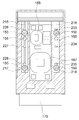
도 5는 본 발명의 일 실시예에 의한 줌렌즈용 자동초점 조절장치의 베이스프레임 일부를 절단하여 나타낸 단면도,
도 6은 본 발명의 다른 실시예에 따른 줌렌즈용 자동초점 조절장치를 분해하여 나타낸 분해 사시도,
도 7은 본 발명의 다른 실시예에 따른 줌렌즈용 자동초점 조절장치의 베이스프레임과 줌렌즈캐리어의 결합 구조를 설명하기 위한 도면,
도 8은 본 발명의 다른 실시예에 따른 줌렌즈용 자동초점 조절장치의 베이스프레임 일부를 절단하여 나타낸 단면도이다. BRIEF DESCRIPTION OF THE DRAWINGS The accompanying drawings, which are incorporated in and constitute a part of the specification, illustrate preferred embodiments of the invention and, together with the detailed description of the invention given below, serve to better understand the technical idea of the invention, And shall not be construed as limited to such matters.
1 is a perspective view illustrating an automatic focusing device for a zoom lens according to an exemplary embodiment of the present invention,
FIG. 2 is an exploded perspective view of an automatic focusing device for a zoom lens according to an embodiment of the present invention,
FIG. 3 is a view illustrating an automatic focusing device for a zoom lens according to an embodiment of the present invention, in which a yoke and a circuit board are exploded from a base frame,
4 is a view for explaining a coupling structure of a base frame and a zoom lens carrier of an automatic focusing device for a zoom lens according to an embodiment of the present invention,
FIG. 5 is a cross-sectional view showing a part of a base frame of an automatic focusing device for a zoom lens according to an embodiment of the present invention,
FIG. 6 is an exploded perspective view of an automatic focusing device for a zoom lens according to another embodiment of the present invention,
7 is a view for explaining a coupling structure of a base frame and a zoom lens carrier of an automatic focusing device for a zoom lens according to another embodiment of the present invention,
FIG. 8 is a cross-sectional view of a portion of a base frame of an automatic focusing device for a zoom lens according to another embodiment of the present invention.
이하, 첨부된 도면을 참조하여 본 발명의 바람직한 실시예를 상세히 설명하기로 한다. 이에 앞서, 본 명세서 및 청구범위에 사용된 용어나 단어는 통상적이거나 사전적인 의미로 한정해서 해석되어서는 아니 되며, 발명자는 그 자신의 발명을 가장 최선의 방법으로 설명하기 위해 용어의 개념을 적절하게 정의할 수 있다는 원칙에 입각하여 본 발명의 기술적 사상에 부합하는 의미와 개념으로 해석되어야만 한다.Hereinafter, preferred embodiments of the present invention will be described in detail with reference to the accompanying drawings. Prior to this, terms and words used in the present specification and claims should not be construed as limited to ordinary or dictionary terms, and the inventor should appropriately interpret the concepts of the terms appropriately It should be interpreted in accordance with the meaning and concept consistent with the technical idea of the present invention based on the principle that it can be defined.
따라서 본 명세서에 기재된 실시예와 도면에 도시된 구성은 본 발명의 가장 바람직한 일 실시예에 불과할 뿐이고 본 발명의 기술적 사상을 모두 대변하는 것은 아니므로, 본 출원시점에 있어서 이들을 대체할 수 있는 다양한 균등물과 변형예들이 있을 수 있음을 이해하여야 한다.Therefore, the embodiments described in the present specification and the configurations shown in the drawings are merely the most preferred embodiments of the present invention and are not intended to represent all of the technical ideas of the present invention. Therefore, various equivalents It should be understood that water and variations may be present.
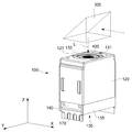
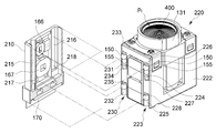
도 1 내지 도 5에 나타낸 것과 같이, 본 발명의 일 실시예에 의한 줌렌즈용 자동초점 조절장치(100)(이하 ‘자동초점 조절장치’라 지칭한다)는 베이스프레임(110), 베이스프레임(110)에 선형 이동 가능하게 결합되는 줌렌즈캐리어(130), 베이스프레임(110)과 줌렌즈캐리어(130) 사이에 배치되는 복수의 볼(150) 및 줌렌즈캐리어(130)를 선행 이동시키기 위한 구동부(160)를 포함할 수 있다.1 to 5, an automatic focusing
상기 복수의 볼(150)은 줌렌즈캐리어(130)가 베이스프레임(110)에 대해 상대 이동할 때 줌렌즈캐리어(130)와 베이스프레임(110) 간의 마찰을 줄여주고, 줌렌즈캐리어(130)가 부드럽게 선형 이동할 수 있도록 유도한다. The plurality of
본 발명의 자동초점 조절장치(100)는 도 1에 도시된 바와 같이 광학계(300)(미러, 프리즘 등)를 통하여 굴절 내지 반사되어 줌렌즈(400)로 유입되는 빛의 경로(L)인 광축 방향(Z축 방향)으로 줌렌즈(400)를 선형 이동시키도록 구성된다. 1, the automatic focusing
광학계(300)는 미러(mirror) 또는 프리즘(prism) 중 선택된 하나 또는 이들의 조합일 수 있으며, 외계에서 유입되는 빛을 본 발명의 자동초점 조절장치(100) 쪽으로 전환시킬 수 있는 다양한 부재로 구현될 수 있다.The
이와 같이 본 발명에 따른 자동초점 조절장치(100)는 광학계(300)에 의하여 광 경로가 굴절된 광의 광축 방향으로 줌렌즈(400)를 선형 이동시켜 줌렌즈(400)의 초점을 조절하도록 구성됨으로써, 휴대 단말기의 두께 방향으로 설치되지 않아도 된다. 따라서 휴대 단말기에 장착되더라도 휴대 단말기의 두께를 증가시키지 않으므로 휴대 단말기의 소형화 등에 최적화될 수 있다.As described above, the automatic focusing
줌렌즈(400)는 복수의 렌즈 내지 렌즈군 또는 프리즘, 미러 등과 같은 광학부재로 구성될 수 있다. 또한 줌렌즈(400)는 광학계(300)를 통과하여 진행하는 광의 광축 방향(Z축 방향)으로 연장된 형상을 가질 수 있다. The
본 발명의 설명에 있어서 줌렌즈(400)의 양쪽 끝단 중 광학계(300)를 통과한 광이 입사되는 쪽을 광입사부(Pi), 광이 출사되어 쪽을 광출사부(Po)로 정의한다. 또한 도면에 나타내지는 않았으나, 줌렌즈(400)의 광출사부(Po)로부터 출사되는 광의 경로 중에는 광 신호를 전기 신호로 변환시키는 CCD, CMOS 등과 같은 촬상소자가 구비될 수 있다.In the description of the present invention, a light incident portion Pi is defined as a side where light passing through the
본 발명의 베이스프레임(110)은 줌렌즈캐리어(130)를 수용하는 일종의 하우징으로서 광이 통과할 수 있는 개구(121)가 상부에 마련된 케이스(120)에 결합되어 휴대 단말기 등에 장착될 수 있다. The
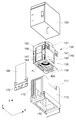
광축 방향을 기준으로 베이스프레임(110)의 상하면에는 개방구(111)(112)가 구비되고, 베이스프레임(110)의 일측면에는 구동 코일부(165)의 설치를 위한 개방구(113)가 형성된다. 베이스프레임(110)은 도시된 구조 이외에, 줌렌즈캐리어(130)를 상대 이동 가능하게 지지할 수 있는 다양한 다른 구조로 변경될 수 있음은 물론이다.
베이스프레임(110)의 개방구(113)가 형성된 측면의 내측에는 제1가이드레일(115) 및 제2가이드레일(116)이 구비되며(도 4 참조), 제1가이드레일(115)과 제2가이드레일(116)은 볼(150)이 부분적으로 수용되는 홈부가 연장된 형태로 이루어질 수 있다. The
제1가이드레일(115)의 하부(광축 방향을 기준으로 아래 방향) 끝단 즉, 광입사부(Pi)에서 먼 쪽 끝단에는 볼(150)의 외부 이탈을 방지하기 위한 제1볼받침부(117)가 구비되며, 제2가이드레일(116)의 하부 끝단에는 볼(150)의 외부 이탈을 방지하기 위한 제2볼받침부(118)가 구비된다. A first
제1볼받침부(117)는 광축 방향을 기준으로 제2볼받침부(118)보다 아래 방향에 위치하도록 구성하여 광축 방향을 기준으로 제1홈부레일(140)의 길이가 제2홈부레일(147)의 길이보다 길게 형성되도록 하는 것이 바람직하다.The first
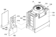
베이스프레임(110)의 제1가이드레일(115) 및 제2가이드레일(116)이 마련된 측면 외측에는 회로기판(170)과 요크(180)가 결합된다. 회로기판(170)에는 구동부(160)를 구성하는 구동 코일부(165), 마그네트부(161)에 인가되는 전류를 제어하는 구동드라이버(172), 홀센서 등의 자기장 센서(174)가 설치된다. 실시형태에 따라서 상기 홀센서(174)와 구동드라이버(172)는 원칩(one chip)으로 구현될 수 있다. The
요크(180)는 줌렌즈캐리어(130)에 구비되는 마그네트부(161)에 인력을 발생시켜 마그네트부(161)가 결합된 줌렌즈캐리어(130)가 요크(180) 쪽으로 당겨지도록 한다. 이러한 요크(180)의 인력에 의하여 줌렌즈캐리어(130)는 베이스프레임(110)의 측면과 볼(150)을 사이에 두고 일정한 간격을 지속적으로 유지할 수 있다.The
이와 같이 마그네트부(161)에 인력을 발생시키는 요크(180)는 독립된 구성으로 베이스프레임(110)에 결합되는 형태는 물론, 인서트 사출에 의하여 베이스프레임(110)에 구비되거나, 또는 베이스프레임 자체가 요크 기능을 할 수 있도록 일체형으로도 구현될 수 있다.The
베이스프레임(110)의 내측에 장착되어 광축 방향으로 선형 이동하는 본 발명의 줌렌즈캐리어(130)는 줌렌즈(400)가 결합되는 줌렌즈 삽입홀(132)이 구비된 줌렌즈배럴(131), 줌렌즈배럴(131)과 결합되어 베이스프레임(110)에 선형 이동 가능하게 결합되는 캐리어 바디(135)를 포함할 수 있다.The
줌렌즈배럴(131)은 실시형태에 따라서 광축 방향과 수직을 이루는 방향으로 상대 이동할 수 있도록 캐리어 바디(135)와 결합될 수도 있다.The
광축 방향을 기준으로 캐리어 바디(135)의 상하면에는 관통구(137)(138)가 각각 형성되고 이 관통구(137)(138)을 통해 줌렌즈배럴(131)의 양쪽 끝단이 외부로 노출될 수 있다. 줌렌즈배럴(131)과 캐리어 바디(135)는 도면에 예시된 바와 같이 분리형 구조가 아닌 일체형 구조로 이루어질 수 있음은 물론이다. Through
캐리어 바디(135)의 일측 외면에는 줌렌즈(400)의 광축 방향과 각각 평행하게 상호 이격되어 배치되는 제1홈부레일(140) 및 제2홈부레일(147)이 구비된다. A first groove bore 140 and a second groove bore 147 are provided on one outer surface of the
도면에 도시된 바와 같이 본 발명의 상기 제1홈부레일(140) 및 제2홈부레일(147)은 광축 방향을 기준으로 각각의 하부 끝단이 캐리어 바디(135)의 끝단 쪽으로 개방된 형태로 이루어진다. As shown in the drawing, the
이들 제1홈부레일(140) 및 제2홈부레일(147)은 베이스프레임(110)의 제1가이드레일(115) 및 제2가이드레일(116)과 각각 마주하게 배치되며, 제1홈부레일(140)과 제1가이드레일(115)의 사이 및 제2홈부레일(147)과 제2가이드레일(116) 사이에 복수의 볼(150)이 배치됨으로써, 캐리어 바디(135)가 베이스프레임(110)에 대해 부드럽게 선형 이동할 수 있다.The
제1홈부레일(140)과 제2홈부레일(147) 각각에 배치되는 볼(150)은 광축 방향과 수직인 방향(X축 방향)으로의 움직임이 제한되고, 제1홈부레일(140)과 제2홈부레일(147) 내에서 각각 구름 운동(rolling) 또는 광축 방향으로의 병진 운동(moving)을 하게 된다. The movement of the
실시형태에 따라서 볼(150)을 사이에 두고 상호 마주하는 제1가이드레일(115)과 제1홈부레일(140) 중 어느 하나만 볼(150)이 부분적으로 삽입되는 홈 형태로 이루어지고, 다른 하나는 평면 형태로 이루어질 수도 있다. 대응되는 관점에서, 상호 마주하는 제2가이드레일(116)과 제2홈부레일(147) 중 어느 하나만 홈 형태로 이루어질 수도 있다.Only one of the
제1홈부레일(140)은 광축 방향을 기준으로 동일선상에 상하로 배치되는 상부홈부레일(141) 및 하부홈부레일(142)을 포함하는 형태 즉, 홈부레일이 이원화된 형태로 구현되는 것이 바람직하다. The
이들 상부홈부레일(141) 및 하부홈부레일(142) 각각에는 볼(150)이 배치되며, 상부홈부레일(141)의 상부(광축 방향을 기준으로 윗 방향) 끝단에는 볼스토퍼(143)가 구비되며, 하부(광축 방향을 기준으로 아래 방향) 끝단에는 볼걸림턱(144)이 구비된다. A
볼스토퍼(143)와 볼걸림턱(144)은 상부홈부레일(141)의 상하 끝단에서 상부홈부레일(141)에 배치되는 볼(150)이 외부로 이탈하는 것을 방지한다. 즉, 볼스토퍼(143)는 볼(150)이 광축 방향을 기준으로 상부 방향으로 이동하는 것을 막아주고, 볼걸림턱(144)은 볼(150)이 하부 방향으로 이동하는 것을 막아준다.The
도시된 바와 같이, 상부홈부레일(141)에는 볼(150)과 함께 볼(150)보다 직경이 작은 보조 볼(155)이 배치될 수 있다. 보조 볼(155)은 볼(150)과 볼걸림턱(144) 사이에 개재되어 볼(150)을 볼걸림턱(144)으로부터 이격시키는 등의 역할을 한다.As shown in the figure, an
이와 같은 구조를 통하여 상부홈부레일(141)에 배치되는 볼(150)이 하부홈부레일(142) 측으로 이동하는 것이 제한되고, 하부홈부레일(142)에 배치되는 볼(150)이 상부홈부레일(141) 측으로 이동하는 것이 제한됨으로써, 줌렌즈캐리어(130)가 베이스프레임(110)에 대해 선형 이동할 때 상부홈부레일(141)의 볼(150)과 하부홈부레일(142)의 볼(150)이 일정 크기 이상의 이격 거리를 유지하며 움직일 수 있어 줌렌즈캐리어(130)의 물리적 지지가 더욱 효과적으로 이루어질 수 있다.The
또한, 하부홈부레일(142)은 그 상부 끝단에 볼(150)의 이탈을 방지하는 볼스토퍼(145)가 구비되나, 도 4에 도시된 바와 같이 하부홈부레일(142)의 하부 끝단은 개방된 형태로 구현되는 것이 바람직하며, 도 4에 도시된 바와 같이 제2홈부레일(147)의 하부 끝단(광축 방향 기준 아래 방향) 또한, 개방된 형태를 이루는 것이 바람직하다. 4, the lower end of the
이와 같이 제1홈부레일(140) 중 하부홈부레일(142) 및 제2홈부레일(147)의 하부가 개방된 구조를 통하여 줌렌즈캐리어(130)가 광축 방향으로 이동하는 경우 하부홈부레일(142) 및 제2홈부레일(147)에 위치한 볼(150)이 함께 이동하는 것을 최소화시킬 수 있어 줌렌즈캐리어(130)의 이동시키는 구동력 즉, 구동 코일부(165)에 인가되는 전력을 저전력 환경으로 개선시킬 수있게 된다.
When the
줌렌즈캐리어(130)가 효과적으로 지지되도록 하기 위하여 제2홈부레일(147)은 제1홈부레일(140)의 상부홈부레일(141) 또는 하부홈부레일(142)보다 길도록 구성하는 것이 바람직하다. The second groove bore 147 may be longer than the upper groove bore 141 or the lower groove bore 142 of the first groove bore 140 in order to effectively support the
도면에 도시된 바와 같이, 제1홈부레일(140)과 제2홈부레일(147) 각각에는 두 개의 볼(150)과 하나의 보조 볼(155)이 배치된다. 이 경우, 제2홈부레일(147)에는 두 개의 볼(150) 사이에 보조 볼(155)이 개재되도록 배치할 수 있다.As shown in the drawing, two
제1홈부레일(140)에는 각각 하나씩의 볼(150)이 상부홈부레일(141) 및 하부홈부레일(142)에 분배되어 배치되도록 하여 제2홈부레일(147)에 배치되는 볼(150)과의 관계에서 줌렌즈캐리어(130)가 전체적으로 3부분에서 지지되도록 구성하는 것이 바람직하다.
One
도 2 내지 도 4에 나타낸 것과 같이, 본 발명의 구동부(160)는 줌렌즈캐리어(130) 또는 베이스프레임(110) 중 어느 하나에 배치되는 마그네트부(161), 줌렌즈캐리어(130) 또는 베이스프레임(110) 중 상기 마그네트부(161)가 배치되지 않는 다른 하나에 배치되는 구동 코일부(165)를 포함한다. 2 to 4, the driving
이하에서는 도면에 예시된 바와 같이 마그네트부(161)가 이동체인 줌렌즈캐리어(130)에 배치되고 구동 코일부(165)가 상대적 고정체인 베이스프레임(110)에 배치되는 예를 기준으로 기술한다.The following description will be made on the basis of an example in which the
마그네트부(161)는 광축 방향을 따라 배치되는 복수의 마그네트(162)(163)를 포함할 수 있다. 마그네트(162)(163)는 줌렌즈캐리어(130)에 대한 구동력을 분산시킬 수 있다면 다양한 개수로 구현될 수 있다. 이하 설명에서는 이해와 설명의 편의성을 높이기 위하여 복수의 마그네트(162)(163)를 제1마그네트(162) 및 제2마그네트(163)로 예시하여 설명하도록 한다.The
구동 코일부(165)는 복수의 마그네트(162)(163)와 각각 마주하도록 광축 방향을 따라 배치되는 복수의 구동 코일(166)(167)을 포함한다. 구동 코일(166)(167)은 마그네트(162)(163)와 마주하도록 광축 방향을 따라 배치되며 각 마그네트(162)(163)와 대응하는 위치에 구비된다. The driving
구동 코일(166)(167) 또한 마그네트(162)(163)와 같이 줌렌즈캐리어(130)에 대한 구동력을 분산시킬 수 있다면 다양한 개수로 구현될 수 있다. 이하 설명에서는 도면에 도시된 예를 기준으로 복수의 구동 코일(166)(167)을 제1구동 코일(166)과 제2구동 코일(167)로 예시하여 설명하도록 한다.The drive coils 166 and 167 may be implemented in various numbers as long as they can distribute the driving force to the
제1구동 코일(166)과 제2구동 코일(167)은 회로기판(170)을 통하여 외부에서 전원이 인가되면, 인가되는 전원의 크기와 방향에 대응되는 전자기력을 발생시키고 발생된 전자기력에 의하여 제1마그네트(162)와 제2마그네트(163) 각각에 구동력을 발생시킨다. 이와 같이 구동력이 발생되면 제1마그네트(162)와 제2마그네트(163)가 구비된 줌렌즈캐리어(130)는 광축 방향을 기준으로 상하 측으로 선형 이동하게 된다.The
이와 관련하여, 홀 효과(hall effect)를 이용하는 홀센서 등 자기장 센서(174)가 마그네트(162)(163)의 위치(즉, 줌렌즈캐리어(130)의 위치)를 감지하여 특정 감지 신호를 구동드라이버(172)로 전달하면, 구동드라이버(172)는 입력된 자기장 센서(174)의 신호를 이용하여 적절한 크기와 방향의 전원이 각 구동 코일(166)(167) 측으로 인가되도록 제어할 수 있다.In this regard, a
이러한 방법을 통하여 광축 방향을 기준으로 줌렌즈캐리어(130)의 정확한 위치를 피드백 제어함으로써 자동초점조절기능이 정밀하게 구현될 수 있다. 구동드라이버(172)는 자기장 센서(174)와는 독립된 형태로 구현될 수도 있고, 자기장 센서(174)와 하나의 모듈 형태로 구현될 수도 있다.By performing feedback control of the exact position of the
앞서 기술된 바와 같이, 줌렌즈캐리어(130)의 줌렌즈배럴(131)은 광축 방향으로 길게 연장된 형상을 가지게 되는데, 종래와 같이 이러한 줌렌즈배럴(131)의 자동초점 구동과 관련하여 단일의 마그네트와 단일의 구동 코일을 배치하는 경우, 줌렌즈배럴(131)의 선형 이동 시 선형 이동 방향에 따라 줌렌즈배럴(131) 윗방향 또는 아래 방향에 미세한 틸트 현상 즉, 자세 불균형에 의한 기울어짐 현상이 발생할 수 있다.As described above, the
줌렌즈배럴(131) 내부에는 복수의 렌즈 등이 구비되고 줌렌즈배럴(131) 자체의 전체 길이가 길므로, 틸트 현상이 미세하더라도 촬상소자에 미치는 영향은 상당하다고 할 수 있다. Since a plurality of lenses and the like are provided in the
본 발명은 마그네트(162)(163)와 구동 코일(166)(167)을 다원화시켜 상하 방향으로 배치하고, 줌렌즈배럴(131)의 수직 길이 방향의 가운데 부분을 기준으로 상측과 하측에 각각 제1마그네트(162)와 제2마그네트(163)를 배치하며, 이들 각각과 제1구동 코일(166)과 제2구동 코일(167) 사이에 전자기력이 발생하도록 함으로써, 하중이 상대적으로 무거워진 줌렌즈배럴(131)의 상하 선형 이동의 구동력을 높임과 동시에, 선형 이동 방향에 따라 상측 또는 하측에서 발생되는 틸트 현상을 효과적으로 방지할 수 있게 된다.The present invention is characterized in that the
구동부(160)는 도시된 것으로 한정되지 않으며, 압전소자, 모터 등과 같은 물리적 구동 수단 등을 포함한 다양한 형태로 구현될 수 있다.
The driving
이하에서는 볼(150)을 매개하여 줌렌즈캐리어(130)가 광축 방향으로 선형 이동하는 작동 관계와 이를 위한 구체적인 구성을 도 4 및 도 5를 참조하여 설명하도록 한다.Hereinafter, the operation of linearly moving the
도시된 것과 같이, 줌렌즈캐리어(130)는 제1홈부레일(140) 및 제2홈부레일(147)이 마련된 외면이 제1가이드레일(115) 및 제2가이드레일(116)이 구비된 베이스프레임(110)의 내면과 마주하도록 베이스프레임(110)에 결합된다. As shown in the figure, the
상호 마주하는 제1홈부레일(140)과 제1가이드레일(115) 사이 및 제2홈부레일(147)과 제2가이드레일(116) 사이에 볼(150)이 배치된다. 줌렌즈캐리어(130)는 요크(180)에 의한 마그네트부(161)의 인력 작용으로 그 외면이 베이스프레임(110)의 내면 쪽으로 당겨지며, 줌렌즈캐리어(130)와 베이스프레임(110)은 각각 볼(150)과 점접촉하게 된다.The
이 상태에서 구동 코일부(165)에 전류가 인가되면 마그네트부(161)와 구동 코일부(165) 간의 전자기적인 상호 작용에 의해 줌렌즈캐리어(130)가 광축 방향으로 이동력을 받게 되며, 이때 볼(150)의 구름 운동과 점접촉에 의하여 최소화된 마찰력으로 줌렌즈캐리어(130)가 선형 이동한다. 따라서 소음의 감소는 물론, 줌렌즈캐리어(130)의 선형 이동을 위한 구동력을 최소화시킬 수 있게 된다.In this state, when a current is applied to the driving
앞서 간략히 설명된 바와 같이 요크(180)와 마그네트부(161) 사이의 인력에 의하여 줌렌즈캐리어(130)는 볼(150)과 점접촉을 지속적으로 유지할 수 있다. 따라서 줌렌즈캐리어(130)가 이탈되지 않음은 물론, 볼(150)의 직경에 대응되는 정확한 이격 거리를 베이스프레임(110)과 유지하면서 선형 이동할 수 있게 된다.The
또한 줌렌즈캐리어(130)가 베이스프레임(110)에 대해 상대 이동할 때, 줌렌즈캐리어(130)와 베이스프레임(110) 사이에 배치되는 복수의 볼(150) 중 일부는 제1가이드레일(115)과 제1홈부레일(140)을 따라 광축 방향으로 가이드되고, 다른 일부의 볼(150)은 제2가이드레일(116)과 제2홈부레일(147)을 따라 광축 방향으로 가이드됨으로써, 줌렌즈캐리어(130)는 더욱 정확하게 광축 방향으로 선형 이동할 수 있다.A portion of the plurality of
한편, 줌렌즈캐리어(130)가 광축 방향을 기준으로 상측으로 움직이는 경우, 줌렌즈캐리어(130) 윗 방향의 물리적 지지가 효과적으로 유지되도록 하기 위하여 상부홈부레일(141)에 배치되는 볼(150)은 볼걸림턱(144)에 의해 상측으로 이동하도록 하는 대신, 하부홈부레일(142)이나 제2홈부레일(147)은 하부 끝단이 개방된 형태로 구현하여 하부홈부레일(142)이나 제2홈부레일(147)에 위치한 볼(150)은 끌려 이동하지 않도록 구성한다.
In order to effectively maintain the upward physical support of the
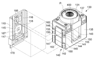
도 6은 본 발명의 다른 실시예에 따른 자동초점 조절장치를 분해하여 나타낸 분해 사시도이다.6 is an exploded perspective view of an automatic focusing device according to another embodiment of the present invention.
도 6에 나타낸 자동초점 조절장치(200)는 베이스프레임(210), 베이스프레임(210)에 선형 이동 가능하게 결합되는 줌렌즈캐리어(220), 베이스프레임(210)과 줌렌즈캐리어(220) 사이에 배치되는 복수의 볼(150), 줌렌즈캐리어(220)를 선행 이동시키기 위한 구동부(160)를 포함한다. 6 includes a
도 6에 도시된 본 발명의 자동초점 조절장치(200)는 상술된 자동초점 조절장치(100)와 비교하여 베이스프레임(210)과 줌렌즈캐리어(220)의 구성 일부가 변형된 것으로, 대부분의 구성은 상술한 것과 같다.6 is a modification of a part of the
베이스프레임(210) 일측면의 내측에는 제1가이드레일(215) 및 제2가이드레일(216)이 구비된다.A
제1가이드레일(215)의 하부 끝단에는 볼(150)의 외부 이탈을 방지하기 위한 제1볼받침부(217)가 구비되고, 제2가이드레일(216)의 광축 방향을 기준으로 하부 끝단에도 볼(150)의 외부 이탈을 방지하기 위한 제2볼받침부(218)가 구비된다. The
제1볼받침부(217)와 제2볼받침부(218)는 같은 높이에 위치할 수 있으며, 제1가이드레일(215)과 제2가이드레일(216)의 길이 또한, 상호 대응되도록 구성할 수 있다.The first
줌렌즈캐리어(220)는 줌렌즈(400)가 결합되는 줌렌즈배럴(131), 줌렌즈배럴(131)과 결합되어 베이스프레임(210)에 선형 이동 가능하게 결합되는 캐리어바디(222)를 포함한다. 줌렌즈배럴(131)은 상술한 것과 같다.The
캐리어바디(222)의 일측 외면에는 줌렌즈(400)의 광축 방향과 각각 평행하게 상호 이격되어 배치되는 제1홈부레일(223) 및 제2홈부레일(230)이 구비된다. A
이들 제1홈부레일(223) 및 제2홈부레일(230)은 광축 방향을 기준으로 각각의 하부 끝단이 캐리어바디(222)의 끝단 쪽으로 개방된 형태로 이루어진다. 이들 제1홈부레일(223) 및 제2홈부레일(230)은 베이스프레임(210)의 제1가이드레일(215) 및 제2가이드레일(216)과 각각 마주하게 배치된다. The first groove bores 223 and the second groove bores 230 are formed such that the lower ends of the first groove bores 223 and the second groove bores 230 open toward the end of the
제1홈부레일(223) 및 제2홈부레일(230)은 각각 광축 방향을 기준으로 동일선상에 상하로 배치되는 상부홈부레일(224)(231) 및 하부홈부레일(225)(232)을 포함할 수 있다.The
각 상부홈부레일(224)(231)의 상부(광축 방향을 기준으로 윗 방향) 끝단에는 볼스토퍼(226)(233)가 구비되며, 하부 끝단에는 볼걸림턱(227)(234)이 구비된다. 각 상부홈부레일(224)(231)에는 볼(150)과 함께 볼(150)보다 직경이 작은 보조 볼(155)이 배치될 수 있다.
각 하부홈부레일(225)(232)의 상부 끝단에는 볼(150)의 이탈을 막아주는 볼스토퍼(228)(235)가 구비되며, 앞서 설명된 바와 같이 각 하부홈부레일(225)(232)의 하부 끝단은 개방된 형태로 이루어진다.
이와 같이, 각 상부홈부레일(224)(231)에 배치되는 볼(150)이 각 하부홈부레일(225)(232) 측으로 이동하는 것을 제한하고, 각 하부홈부레일(225)(232)에 배치되는 볼(150)이 각 상부홈부레일(224)(231) 측으로 이동하는 것을 제한함으로써, 줌렌즈캐리어(220)가 베이스프레임(210)에 대해 선형 이동할 때 제1홈부레일(223) 및 제2홈부레일(230) 각각에 배치되는 볼들(150)은 일정 거리 이상의 이격 거리를 유지할 수 있다.In this way, the
특히, 제1홈부레일(223) 및 제2홈부레일(230)에 각각 배치되는 볼들(150)이 상부홈부레일(224)(231) 및 하부홈부레일(225)(232)에 각각 하나 이상씩 배치되어 일정 크기 이상의 간격을 유지할 수 있으므로 줌렌즈캐리어(220)는 더욱 안정적으로 균형을 유지할 수 있다.Particularly when the
한편, 줌렌즈캐리어(220)가 광축 방향을 기준으로 상측으로 움직이는 경우, 각 하부홈부레일(225)(232)은 하부 끝단이 개방된 형태로 이루어짐으로써, 하부홈부레일(225)(232) 내에 위치한 볼(150)이 줌렌즈캐리어(220)와 함께 이동하는 현상을 억제시킬 수 있어 소음의 감소는 물론, 줌렌즈캐리어(220)의 선형 이동을 위한 구동력을 최소화시킬 수있다.
When the
이상에서 본 발명은 비록 한정된 실시예와 도면에 의해 설명되었으나, 본 발명은 이것에 의해 한정되지 않으며 본 발명이 속하는 기술분야에서 통상의 지식을 가진 자에 의해 본 발명의 기술사상과 아래에 기재될 특허청구범위의 균등범위 내에서 다양한 수정 및 변형이 가능함은 물론이다.While the present invention has been particularly shown and described with reference to exemplary embodiments thereof, it is to be understood that the invention is not to be limited to the details thereof and that various changes and modifications will be apparent to those skilled in the art. And various modifications and variations are possible within the scope of the appended claims.
또한 본 발명의 설명에 있어 제1, 제2 또는 상, 하 등과 같은 표현은 상호 간의 각 구성(요소)을 상대적으로 구분하기 위하여 사용되는 도구적 개념의 용어일 뿐, 특정의 순서, 우선순위 등을 나타내기 위하여 사용되는 용어이거나, 절대적인 기준에서 각각의 구성(요소)을 물리적으로 구분하기 위하여 사용되는 용어가 아님은 자명하다.In addition, in the description of the present invention, the first, second, upper, and lower expressions are terms of a tool concept used to relatively divide the respective elements (elements) , Or it is obvious that it is not a term used to physically distinguish each component (element) from an absolute reference.
본 발명의 설명과 그에 대한 실시예의 도시를 위하여 첨부된 도면 등은 본 발명에 의한 기술 내용을 강조 내지 부각하기 위하여 다소 과장된 형태로 도시될 수 있으나, 앞서 기술된 내용과 도면에 도시된 사항 등을 고려하여 본 기술분야의 통상의 기술자 수준에서 다양한 형태의 변형 적용 예가 가능할 수 있음은 자명하다고 해석되어야 한다.It is to be understood that both the foregoing general description and the following detailed description are exemplary and explanatory and are intended to provide further explanation of the invention as claimed. It should be understood that various modifications may be made in the ordinary skill in the art.
100, 200 : 줌렌즈용 자동초점 조절장치
110, 210 : 베이스프레임
115, 215 : 제1가이드레일
116, 216 : 제2가이드레일
117, 217 : 제1볼받침부
118, 218 : 제2볼받침부
120 : 케이스
130, 220 : 줌렌즈캐리어
131 : 줌렌즈배럴
135, 222 : 캐리어 바디
140, 223 : 제1홈부레일
141, 224, 231 : 상부홈부레일
142, 225, 232 : 하부홈부레일
143, 145, 148, 226, 228, 233, 235: 볼스토퍼
144, 227, 234 : 볼걸림턱
147, 230 : 제2홈부레일
150 : 볼
155 : 보조 볼
160 : 구동부
161 : 마그네트부
162, 163 : 제1, 2마그네트
165 : 구동 코일부
166, 167 : 제1, 2구동 코일
170 : 회로기판
172 : 구동드라이버
174 : 자기장 센서
180 : 요크100, 200: Auto focusing device for zoom lens
110, 210:
116, 216:
118, 218: second ball bearing part 120: case
130, 220: zoom lens carrier 131: zoom lens barrel
135, 222:
141, 224, 231: upper groove bores 142, 225, 232: lower groove bores
143, 145, 148, 226, 228, 233, 235:
144, 227, 234:
150: Ball 155: Secondary ball
160: Driving section 161: Magnet section
162, 163: first and second magnets 165: driving coil part
166, 167: first and second drive coils 170: circuit board
172: drive driver 174: magnetic field sensor
180: York
Claims (9)
상기 제1 및 제2가이드레일 각각에 대응되도록 배치되는 제1 및 제2홈부레일이 구비되고, 광축 방향으로 선형 이동하는 줌렌즈캐리어;
상기 줌렌즈캐리어를 상기 광축 방향으로 선형 이동시키는 구동부; 및
상기 제1홈부레일과 제1가이드레일 사이 및 상기 제2홈부레일과 제2가이드레일 사이에 배치되며 상기 제1 및 제2볼 받침부에 의하여 외부 이탈이 방지되는 복수 개의 볼을 포함하는 것을 특징으로 하는 자동초점 조절장치. A base frame including first and second guide rails spaced apart from each other and first and second ball receivers provided at ends of the first and second guide rails;
A zoom lens carrier having first and second groove bores arranged to correspond to the first and second guide rails, respectively, and linearly moving in the optical axis direction;
A driving unit for linearly moving the zoom lens carrier in the optical axis direction; And
And a plurality of balls disposed between the first groove guide and the first guide rail and between the second groove guide and the second guide rail and prevented from being detached by the first and second ball support portions. And an auto-focusing device.
상기 볼이 상기 광축 방향을 기준으로 상부 방향으로 이동하는 것을 방지하는 볼스토퍼가 각각 구비되는 것을 특징으로 하는 줌렌즈용 자동초점 조절장치.2. The apparatus of claim 1, wherein the first and second groove-
And a ball stopper for preventing the ball from moving upward with respect to the optical axis direction.
상기 광축 방향을 기준으로 하부 끝단이 개방된 형태로 이루어지는 것을 특징으로 하는 줌렌즈용 자동초점 조절장치.2. The apparatus of claim 1, wherein at least one of the first and second groove < RTI ID = 0.0 >
And the lower end of the zoom lens is opened with respect to the optical axis direction.
상기 광축 방향을 기준으로 동일선상에 상하로 배치되는 상부홈부레일 및 하부홈부레일을 포함하며,
상기 상부홈부레일은 상기 광축 방향을 기준으로 상부 끝단에 상기 볼스토퍼가 구비되며, 상기 광축 방향을 기준으로 하부 끝단에 상기 볼의 이탈을 방지하는 볼걸림턱이 구비되며,
상기 하부홈부레일은 상기 광축 방향을 기준으로 상부 끝단에 상기 볼스토퍼가 구비되며, 상기 광축 방향을 기준으로 하부 끝단이 개방된 형태로 이루어지는 것을 특징으로 하는 줌렌즈용 자동초점 조절장치.3. The apparatus according to claim 2, wherein the first groove-
And upper and lower grooved bobbins arranged on the same line on the basis of the optical axis direction,
Wherein the upper groove bobbin includes a ball stopper at an upper end thereof with respect to the optical axis direction and a ball catching jaw at a lower end of the ball end stopper to prevent the ball from being separated from the optical axis direction,
Wherein the lower groove bore includes the ball stopper at an upper end with respect to the optical axis direction and has a lower end opened with respect to the optical axis direction.
상기 광축 방향을 기준으로 상기 제2볼받침부보다 아래 방향에 위치하여 상기 광축 방향을 기준으로 상기 제1홈부레일의 길이가 상기 제2홈부레일의 길이보다 길게 형성되는 것을 특징으로 하는 줌렌즈용 자동초점 조절장치.[2] The apparatus of claim 1, wherein the first ball-
And the length of the first groove bobbin is longer than the length of the second groove bobbin with respect to the direction of the optical axis, the first groove bobbin being positioned below the second ball receiving unit with respect to the optical axis direction. For example.
상기 광축 방향을 기준으로 상기 제2홈부레일에 구비되는 볼스토퍼보다 상부에 배치되는 것을 특징으로 하는 줌렌즈용 자동초점 조절장치.[5] The apparatus of claim 4, wherein the ball stopper provided on the upper groove bushing of the first groove bushing comprises:
Wherein the second stopper is disposed above the ball stopper provided on the second groove bore with respect to the optical axis direction.
상기 광축 방향을 기준으로 동일선상에 상하로 배치되는 상부홈부레일 및 하부홈부레일을 포함하며,
상기 상부홈부레일은 상기 광축 방향을 기준으로 상부 끝단에 상기 볼스토퍼가 구비되며, 상기 광축 방향을 기준으로 하부 끝단에 상기 볼의 이탈을 방지하는 볼걸림턱이 구비되며,
상기 하부홈부레일은 상기 광축 방향을 기준으로 상부 끝단에 상기 볼스토퍼가 구비되며, 상기 광축 방향을 기준으로 하부 끝단이 개방된 형태로 이루어지는 것을 특징으로 하는 줌렌즈용 자동초점 조절장치.3. The apparatus of claim 2, wherein each of the first and second groove-
And upper and lower grooved bobbins arranged on the same line on the basis of the optical axis direction,
Wherein the upper groove bobbin includes a ball stopper at an upper end thereof with respect to the optical axis direction and a ball catching jaw at a lower end of the ball end stopper to prevent the ball from being separated from the optical axis direction,
Wherein the lower groove bore includes the ball stopper at an upper end with respect to the optical axis direction and has a lower end opened with respect to the optical axis direction.
상기 줌렌즈캐리어 또는 상기 베이스프레임 중 어느 하나에 배치되는 마그네트부; 및
상기 줌렌즈캐리어 또는 상기 베이스프레임 중 상기 마그네트부가 배치되지 않는 다른 하나에 배치되고, 상기 줌렌즈캐리어를 상기 광축 방향으로 선형 이동시킬 수 있도록 상기 마그네트부에 전자기력을 발생시키는 구동 코일부를 포함하는 것을 특징으로 하는 줌렌즈용 자동초점 조절장치.The driving apparatus according to claim 1,
A magnet portion disposed on any one of the zoom lens carrier and the base frame; And
And a driving coil part that is disposed on the other of the zoom lens carrier or the other of the base frames and on which the magnet part is not disposed and that generates an electromagnetic force in the magnet part so as to linearly move the zoom lens carrier in the optical axis direction. A zoom lens for zooming.
상기 광축 방향을 따라 배치되는 복수의 마그네트를 포함하고, 상기 구동 코일부는 상기 복수의 마그네트와 각각 마주하도록 상기 광축 방향을 따라 배치되는 복수의 구동 코일을 포함하는 것을 특징으로 하는 줌렌즈용 자동초점 조절장치.The magnetron according to claim 8,
And a plurality of magnets disposed along the optical axis direction, wherein the drive coil unit includes a plurality of drive coils disposed along the optical axis direction so as to face the plurality of magnets, respectively, .
Priority Applications (1)
| Application Number | Priority Date | Filing Date | Title |
|---|---|---|---|
| KR1020170025137A KR102350710B1 (en) | 2017-02-25 | 2017-02-25 | Auto focussing apparatus for zoom lens |
Applications Claiming Priority (1)
| Application Number | Priority Date | Filing Date | Title |
|---|---|---|---|
| KR1020170025137A KR102350710B1 (en) | 2017-02-25 | 2017-02-25 | Auto focussing apparatus for zoom lens |
Publications (2)
| Publication Number | Publication Date |
|---|---|
| KR20180098463A true KR20180098463A (en) | 2018-09-04 |
| KR102350710B1 KR102350710B1 (en) | 2022-01-14 |
Family
ID=63598210
Family Applications (1)
| Application Number | Title | Priority Date | Filing Date |
|---|---|---|---|
| KR1020170025137A Active KR102350710B1 (en) | 2017-02-25 | 2017-02-25 | Auto focussing apparatus for zoom lens |
Country Status (1)
| Country | Link |
|---|---|
| KR (1) | KR102350710B1 (en) |
Cited By (24)
| Publication number | Priority date | Publication date | Assignee | Title |
|---|---|---|---|---|
| KR20200035522A (en) * | 2018-09-27 | 2020-04-06 | 자화전자(주) | Apparatus for operating lens |
| KR20200043056A (en) * | 2018-10-17 | 2020-04-27 | 자화전자(주) | Actuator mounted with structure of multi magnetic pole magnet |
| KR20200051354A (en) * | 2018-11-05 | 2020-05-13 | 삼성전기주식회사 | rens module and camera module having the same |
| WO2020101135A1 (en) * | 2018-11-15 | 2020-05-22 | 자화전자 주식회사 | Optical system driving device, optical system position control device, and position control method |
| WO2020209598A1 (en) * | 2019-04-10 | 2020-10-15 | 엘지이노텍 주식회사 | Camera module and camera apparatus comprising same |
| KR20210028635A (en) * | 2018-10-17 | 2021-03-12 | 자화전자(주) | Actuator mounted with structure of multi magnetic pole magnet |
| KR102313876B1 (en) | 2020-07-02 | 2021-10-18 | 자화전자(주) | Actuator for camera and camera module including it |
| US20220103725A1 (en) * | 2020-09-29 | 2022-03-31 | Samsung Electro-Mechanics Co., Ltd. | Camera module |
| WO2022086158A1 (en) * | 2020-10-21 | 2022-04-28 | 엘지이노텍 주식회사 | Camera actuator and camera module including same |
| CN114500785A (en) * | 2020-11-12 | 2022-05-13 | 磁化电子公司 | Zoom driving actuator |
| CN114721111A (en) * | 2020-12-18 | 2022-07-08 | 宁波舜宇光电信息有限公司 | Optical zoom camera module |
| CN114755875A (en) * | 2020-12-29 | 2022-07-15 | 三星电机株式会社 | Camera module |
| WO2022154244A1 (en) * | 2021-01-13 | 2022-07-21 | 자화전자(주) | Zoom drive actuator |
| WO2022235109A1 (en) * | 2021-05-06 | 2022-11-10 | 엘지이노텍 주식회사 | Camera actuator and camera device comprising same |
| CN116648652A (en) * | 2020-12-18 | 2023-08-25 | 宁波舜宇光电信息有限公司 | Optical zoom camera module and corresponding portable terminal equipment |
| JP2024015082A (en) * | 2019-12-26 | 2024-02-01 | ミツミ電機株式会社 | Lens drive device, camera module and camera mounting device |
| WO2024117849A1 (en) * | 2022-12-01 | 2024-06-06 | 엘지이노텍 주식회사 | Camera actuator |
| US12032219B2 (en) | 2019-04-30 | 2024-07-09 | Samsung Electro-Mechanics Co., Ltd. | Camera module |
| WO2024155016A1 (en) * | 2023-01-18 | 2024-07-25 | 엘지이노텍 주식회사 | Camera actuator and camera module including same |
| US12066691B2 (en) | 2021-02-03 | 2024-08-20 | Largan Digital Co., Ltd. | Lens driving module, photographing camera and electronic device |
| WO2025159406A1 (en) * | 2024-01-25 | 2025-07-31 | 엘지이노텍(주) | Lens driving device, and camera device and optical instrument comprising same |
| US12422642B2 (en) | 2021-12-08 | 2025-09-23 | Samsung Electro-Mechanics Co., Ltd. | Camera module |
| EP4439170A4 (en) * | 2021-11-24 | 2025-10-15 | Lg Innotek Co Ltd | CAMERA ACTUATOR, LENS TRANSFER DEVICE AND CAMERA DEVICE THEREOF |
| US12449632B2 (en) | 2021-03-09 | 2025-10-21 | Samsung Electro-Mechanics Co., Ltd. | Camera module |
Families Citing this family (1)
| Publication number | Priority date | Publication date | Assignee | Title |
|---|---|---|---|---|
| KR20230166937A (en) | 2022-05-30 | 2023-12-07 | 이호재 | Wireless robotic focusing device for telescopes |
Citations (4)
| Publication number | Priority date | Publication date | Assignee | Title |
|---|---|---|---|---|
| KR100849580B1 (en) * | 2007-04-10 | 2008-07-31 | 삼성전자주식회사 | Camera lens assembly |
| JP2012103373A (en) * | 2010-11-09 | 2012-05-31 | Shicoh Engineering Co Ltd | Lens drive device, autofocus camera and camera-equipped mobile terminal |
| KR101643771B1 (en) * | 2008-10-30 | 2016-07-29 | 삼성전자주식회사 | Camera lens assembly |
| KR101704498B1 (en) * | 2016-03-10 | 2017-02-09 | 자화전자(주) | Apparatus for auto focus with 3 location supporting structure |
-
2017
- 2017-02-25 KR KR1020170025137A patent/KR102350710B1/en active Active
Patent Citations (4)
| Publication number | Priority date | Publication date | Assignee | Title |
|---|---|---|---|---|
| KR100849580B1 (en) * | 2007-04-10 | 2008-07-31 | 삼성전자주식회사 | Camera lens assembly |
| KR101643771B1 (en) * | 2008-10-30 | 2016-07-29 | 삼성전자주식회사 | Camera lens assembly |
| JP2012103373A (en) * | 2010-11-09 | 2012-05-31 | Shicoh Engineering Co Ltd | Lens drive device, autofocus camera and camera-equipped mobile terminal |
| KR101704498B1 (en) * | 2016-03-10 | 2017-02-09 | 자화전자(주) | Apparatus for auto focus with 3 location supporting structure |
Cited By (35)
| Publication number | Priority date | Publication date | Assignee | Title |
|---|---|---|---|---|
| KR20200035522A (en) * | 2018-09-27 | 2020-04-06 | 자화전자(주) | Apparatus for operating lens |
| KR20210028635A (en) * | 2018-10-17 | 2021-03-12 | 자화전자(주) | Actuator mounted with structure of multi magnetic pole magnet |
| KR20200043056A (en) * | 2018-10-17 | 2020-04-27 | 자화전자(주) | Actuator mounted with structure of multi magnetic pole magnet |
| US11824417B2 (en) | 2018-10-17 | 2023-11-21 | Jahwa Electronics Co., Ltd. | Actuator with multipolar magnet structure |
| KR20200051354A (en) * | 2018-11-05 | 2020-05-13 | 삼성전기주식회사 | rens module and camera module having the same |
| WO2020101135A1 (en) * | 2018-11-15 | 2020-05-22 | 자화전자 주식회사 | Optical system driving device, optical system position control device, and position control method |
| KR20200119630A (en) * | 2019-04-10 | 2020-10-20 | 엘지이노텍 주식회사 | Camera module and Camera Apparatus including the same |
| WO2020209598A1 (en) * | 2019-04-10 | 2020-10-15 | 엘지이노텍 주식회사 | Camera module and camera apparatus comprising same |
| US12298591B2 (en) | 2019-04-10 | 2025-05-13 | Lg Innotek Co., Ltd. | Camera module and camera apparatus comprising same |
| US12607819B2 (en) | 2019-04-30 | 2026-04-21 | Samsung Electro-Mechanics Co., Ltd. | Camera module |
| US12554093B2 (en) | 2019-04-30 | 2026-02-17 | Samsung Electro-Mechanics Co., Ltd. | Camera module |
| US12032219B2 (en) | 2019-04-30 | 2024-07-09 | Samsung Electro-Mechanics Co., Ltd. | Camera module |
| JP2024015082A (en) * | 2019-12-26 | 2024-02-01 | ミツミ電機株式会社 | Lens drive device, camera module and camera mounting device |
| KR102313876B1 (en) | 2020-07-02 | 2021-10-18 | 자화전자(주) | Actuator for camera and camera module including it |
| US20220103725A1 (en) * | 2020-09-29 | 2022-03-31 | Samsung Electro-Mechanics Co., Ltd. | Camera module |
| CN114355703A (en) * | 2020-09-29 | 2022-04-15 | 三星电机株式会社 | Camera module |
| WO2022086158A1 (en) * | 2020-10-21 | 2022-04-28 | 엘지이노텍 주식회사 | Camera actuator and camera module including same |
| US12429748B2 (en) | 2020-10-21 | 2025-09-30 | Lg Innotek Co., Ltd. | Camera actuator and camera module including same |
| CN114500785A (en) * | 2020-11-12 | 2022-05-13 | 磁化电子公司 | Zoom driving actuator |
| CN114721111B (en) * | 2020-12-18 | 2023-08-11 | 宁波舜宇光电信息有限公司 | Optical zoom camera module |
| CN116648652A (en) * | 2020-12-18 | 2023-08-25 | 宁波舜宇光电信息有限公司 | Optical zoom camera module and corresponding portable terminal equipment |
| CN114721111A (en) * | 2020-12-18 | 2022-07-08 | 宁波舜宇光电信息有限公司 | Optical zoom camera module |
| CN114755875A (en) * | 2020-12-29 | 2022-07-15 | 三星电机株式会社 | Camera module |
| US12382155B2 (en) | 2020-12-29 | 2025-08-05 | Samsung Electro-Mechanics Co., Ltd. | Camera module and mobile device including the same |
| WO2022154244A1 (en) * | 2021-01-13 | 2022-07-21 | 자화전자(주) | Zoom drive actuator |
| US12066691B2 (en) | 2021-02-03 | 2024-08-20 | Largan Digital Co., Ltd. | Lens driving module, photographing camera and electronic device |
| US12449632B2 (en) | 2021-03-09 | 2025-10-21 | Samsung Electro-Mechanics Co., Ltd. | Camera module |
| WO2022235109A1 (en) * | 2021-05-06 | 2022-11-10 | 엘지이노텍 주식회사 | Camera actuator and camera device comprising same |
| US12452511B2 (en) | 2021-05-06 | 2025-10-21 | Lg Innotek Co., Ltd. | Camera actuator and camera device comprising same |
| EP4439170A4 (en) * | 2021-11-24 | 2025-10-15 | Lg Innotek Co Ltd | CAMERA ACTUATOR, LENS TRANSFER DEVICE AND CAMERA DEVICE THEREOF |
| US12422642B2 (en) | 2021-12-08 | 2025-09-23 | Samsung Electro-Mechanics Co., Ltd. | Camera module |
| WO2024117849A1 (en) * | 2022-12-01 | 2024-06-06 | 엘지이노텍 주식회사 | Camera actuator |
| EP4628986A4 (en) * | 2022-12-01 | 2026-03-18 | Lg Innotek Co Ltd | CAMERA ACTUATOR |
| WO2024155016A1 (en) * | 2023-01-18 | 2024-07-25 | 엘지이노텍 주식회사 | Camera actuator and camera module including same |
| WO2025159406A1 (en) * | 2024-01-25 | 2025-07-31 | 엘지이노텍(주) | Lens driving device, and camera device and optical instrument comprising same |
Also Published As
| Publication number | Publication date |
|---|---|
| KR102350710B1 (en) | 2022-01-14 |
Similar Documents
| Publication | Publication Date | Title |
|---|---|---|
| KR20180098463A (en) | Auto focussing apparatus for zoom lens | |
| KR102400386B1 (en) | Apparatus for driving zoom lens | |
| KR102423363B1 (en) | Actuator for zoom camera | |
| US11824417B2 (en) | Actuator with multipolar magnet structure | |
| KR102090625B1 (en) | Apparatus for auto focus and camera module including it | |
| US11163133B2 (en) | Camera actuator and compact camera including same | |
| USRE49010E1 (en) | Auto-focusing apparatus having asymmetric supporting structure | |
| KR20180096073A (en) | Apparatus for driving optical-reflector for ois with multi-axisal structure | |
| KR20180116965A (en) | Camera module actuator | |
| KR20180120894A (en) | Apparatus for driving optical-reflector with multi-axial structure | |
| KR102433193B1 (en) | Actuator for camera with module combination | |
| KR102423685B1 (en) | Apparatus for operating lens | |
| KR20180015966A (en) | Actuator for zoom lens | |
| KR101862228B1 (en) | Apparatus for driving optical-reflector for ois | |
| KR101889835B1 (en) | Camera module for portable device | |
| US11860445B2 (en) | Actuator for driving reflector | |
| CN116324613A (en) | Zoom driving actuator and position control method for zoom driving | |
| KR20210014875A (en) | Lens assembly moving device and camera module including the same | |
| KR20190024443A (en) | Actuator for optical use | |
| CN114721111B (en) | Optical zoom camera module | |
| CN119805839A (en) | Reflector actuator | |
| KR20220064525A (en) | Actuator for driving zoom | |
| US20240345360A1 (en) | Hybrid actuator for zoom driving | |
| CN114730122B (en) | Reflector actuator and camera module including the reflector actuator | |
| CN114651210B (en) | Camera actuator and camera device including the same |
Legal Events
| Date | Code | Title | Description |
|---|---|---|---|
| PA0109 | Patent application |
St.27 status event code: A-0-1-A10-A12-nap-PA0109 |
|
| PG1501 | Laying open of application |
St.27 status event code: A-1-1-Q10-Q12-nap-PG1501 |
|
| R18-X000 | Changes to party contact information recorded |
St.27 status event code: A-3-3-R10-R18-oth-X000 |
|
| A201 | Request for examination | ||
| PA0201 | Request for examination |
St.27 status event code: A-1-2-D10-D11-exm-PA0201 |
|
| D13-X000 | Search requested |
St.27 status event code: A-1-2-D10-D13-srh-X000 |
|
| D14-X000 | Search report completed |
St.27 status event code: A-1-2-D10-D14-srh-X000 |
|
| E902 | Notification of reason for refusal | ||
| PE0902 | Notice of grounds for rejection |
St.27 status event code: A-1-2-D10-D21-exm-PE0902 |
|
| E13-X000 | Pre-grant limitation requested |
St.27 status event code: A-2-3-E10-E13-lim-X000 |
|
| P11-X000 | Amendment of application requested |
St.27 status event code: A-2-2-P10-P11-nap-X000 |
|
| P13-X000 | Application amended |
St.27 status event code: A-2-2-P10-P13-nap-X000 |
|
| E701 | Decision to grant or registration of patent right | ||
| PE0701 | Decision of registration |
St.27 status event code: A-1-2-D10-D22-exm-PE0701 |
|
| GRNT | Written decision to grant | ||
| PR0701 | Registration of establishment |
St.27 status event code: A-2-4-F10-F11-exm-PR0701 |
|
| PR1002 | Payment of registration fee |
St.27 status event code: A-2-2-U10-U11-oth-PR1002 Fee payment year number: 1 |
|
| PG1601 | Publication of registration |
St.27 status event code: A-4-4-Q10-Q13-nap-PG1601 |
|
| P22-X000 | Classification modified |
St.27 status event code: A-4-4-P10-P22-nap-X000 |
|
| PR1001 | Payment of annual fee |
St.27 status event code: A-4-4-U10-U11-oth-PR1001 Fee payment year number: 4 |
|
| PR1001 | Payment of annual fee |
St.27 status event code: A-4-4-U10-U11-oth-PR1001 Fee payment year number: 5 |
|
| U11 | Full renewal or maintenance fee paid |
Free format text: ST27 STATUS EVENT CODE: A-4-4-U10-U11-OTH-PR1001 (AS PROVIDED BY THE NATIONAL OFFICE) Year of fee payment: 5 |