KR20180098425A - DEVICE AND METHOD FOR ELECTRICALLY CLOSURE OF VEHICLE DOOR - Google Patents
DEVICE AND METHOD FOR ELECTRICALLY CLOSURE OF VEHICLE DOOR Download PDFInfo
- Publication number
- KR20180098425A KR20180098425A KR1020187024488A KR20187024488A KR20180098425A KR 20180098425 A KR20180098425 A KR 20180098425A KR 1020187024488 A KR1020187024488 A KR 1020187024488A KR 20187024488 A KR20187024488 A KR 20187024488A KR 20180098425 A KR20180098425 A KR 20180098425A
- Authority
- KR
- South Korea
- Prior art keywords
- door
- pulley
- cable
- actuator
- hub
- Prior art date
- Legal status (The legal status is an assumption and is not a legal conclusion. Google has not performed a legal analysis and makes no representation as to the accuracy of the status listed.)
- Granted
Links
Images


Classifications
-
- E—FIXED CONSTRUCTIONS
- E05—LOCKS; KEYS; WINDOW OR DOOR FITTINGS; SAFES
- E05F—DEVICES FOR MOVING WINGS INTO OPEN OR CLOSED POSITION; CHECKS FOR WINGS; WING FITTINGS NOT OTHERWISE PROVIDED FOR, CONCERNED WITH THE FUNCTIONING OF THE WING
- E05F15/00—Power-operated mechanisms for wings
- E05F15/60—Power-operated mechanisms for wings using electrical actuators
- E05F15/603—Power-operated mechanisms for wings using electrical actuators using rotary electromotors
- E05F15/611—Power-operated mechanisms for wings using electrical actuators using rotary electromotors for swinging wings
- E05F15/627—Power-operated mechanisms for wings using electrical actuators using rotary electromotors for swinging wings operated by flexible elongated pulling elements, e.g. belts, chains or cables
-
- B—PERFORMING OPERATIONS; TRANSPORTING
- B60—VEHICLES IN GENERAL
- B60J—WINDOWS, WINDSCREENS, NON-FIXED ROOFS, DOORS, OR SIMILAR DEVICES FOR VEHICLES; REMOVABLE EXTERNAL PROTECTIVE COVERINGS SPECIALLY ADAPTED FOR VEHICLES
- B60J5/00—Doors
- B60J5/04—Doors arranged at the vehicle sides
- B60J5/0486—Special type
-
- E—FIXED CONSTRUCTIONS
- E05—LOCKS; KEYS; WINDOW OR DOOR FITTINGS; SAFES
- E05B—LOCKS; ACCESSORIES THEREFOR; HANDCUFFS
- E05B79/00—Mounting or connecting vehicle locks or parts thereof
- E05B79/10—Connections between movable lock parts
- E05B79/20—Connections between movable lock parts using flexible connections, e.g. Bowden cables
-
- E—FIXED CONSTRUCTIONS
- E05—LOCKS; KEYS; WINDOW OR DOOR FITTINGS; SAFES
- E05B—LOCKS; ACCESSORIES THEREFOR; HANDCUFFS
- E05B81/00—Power-actuated vehicle locks
- E05B81/24—Power-actuated vehicle locks characterised by constructional features of the actuator or the power transmission
- E05B81/32—Details of the actuator transmission
- E05B81/34—Details of the actuator transmission of geared transmissions
- E05B81/38—Planetary gears
-
- E—FIXED CONSTRUCTIONS
- E05—LOCKS; KEYS; WINDOW OR DOOR FITTINGS; SAFES
- E05B—LOCKS; ACCESSORIES THEREFOR; HANDCUFFS
- E05B81/00—Power-actuated vehicle locks
- E05B81/54—Electrical circuits
- E05B81/64—Monitoring or sensing, e.g. by using switches or sensors
-
- E—FIXED CONSTRUCTIONS
- E05—LOCKS; KEYS; WINDOW OR DOOR FITTINGS; SAFES
- E05B—LOCKS; ACCESSORIES THEREFOR; HANDCUFFS
- E05B81/00—Power-actuated vehicle locks
- E05B81/54—Electrical circuits
- E05B81/64—Monitoring or sensing, e.g. by using switches or sensors
- E05B81/70—Monitoring or sensing, e.g. by using switches or sensors the wing position
-
- E—FIXED CONSTRUCTIONS
- E05—LOCKS; KEYS; WINDOW OR DOOR FITTINGS; SAFES
- E05C—BOLTS OR FASTENING DEVICES FOR WINGS, SPECIALLY FOR DOORS OR WINDOWS
- E05C17/00—Devices for holding wings open; Devices for limiting opening of wings or for holding wings open by a movable member extending between frame and wing; Braking devices, stops or buffers, combined therewith
- E05C17/02—Devices for holding wings open; Devices for limiting opening of wings or for holding wings open by a movable member extending between frame and wing; Braking devices, stops or buffers, combined therewith by mechanical means
- E05C17/04—Devices for holding wings open; Devices for limiting opening of wings or for holding wings open by a movable member extending between frame and wing; Braking devices, stops or buffers, combined therewith by mechanical means with a movable bar or equivalent member extending between frame and wing
- E05C17/12—Devices for holding wings open; Devices for limiting opening of wings or for holding wings open by a movable member extending between frame and wing; Braking devices, stops or buffers, combined therewith by mechanical means with a movable bar or equivalent member extending between frame and wing consisting of a single rod
- E05C17/20—Devices for holding wings open; Devices for limiting opening of wings or for holding wings open by a movable member extending between frame and wing; Braking devices, stops or buffers, combined therewith by mechanical means with a movable bar or equivalent member extending between frame and wing consisting of a single rod sliding through a guide
- E05C17/203—Devices for holding wings open; Devices for limiting opening of wings or for holding wings open by a movable member extending between frame and wing; Braking devices, stops or buffers, combined therewith by mechanical means with a movable bar or equivalent member extending between frame and wing consisting of a single rod sliding through a guide concealed, e.g. for vehicles
-
- E—FIXED CONSTRUCTIONS
- E05—LOCKS; KEYS; WINDOW OR DOOR FITTINGS; SAFES
- E05F—DEVICES FOR MOVING WINGS INTO OPEN OR CLOSED POSITION; CHECKS FOR WINGS; WING FITTINGS NOT OTHERWISE PROVIDED FOR, CONCERNED WITH THE FUNCTIONING OF THE WING
- E05F15/00—Power-operated mechanisms for wings
- E05F15/60—Power-operated mechanisms for wings using electrical actuators
- E05F15/603—Power-operated mechanisms for wings using electrical actuators using rotary electromotors
- E05F15/611—Power-operated mechanisms for wings using electrical actuators using rotary electromotors for swinging wings
- E05F15/63—Power-operated mechanisms for wings using electrical actuators using rotary electromotors for swinging wings operated by swinging arms
-
- E—FIXED CONSTRUCTIONS
- E05—LOCKS; KEYS; WINDOW OR DOOR FITTINGS; SAFES
- E05F—DEVICES FOR MOVING WINGS INTO OPEN OR CLOSED POSITION; CHECKS FOR WINGS; WING FITTINGS NOT OTHERWISE PROVIDED FOR, CONCERNED WITH THE FUNCTIONING OF THE WING
- E05F15/00—Power-operated mechanisms for wings
- E05F15/70—Power-operated mechanisms for wings with automatic actuation
- E05F15/79—Power-operated mechanisms for wings with automatic actuation using time control
-
- E—FIXED CONSTRUCTIONS
- E05—LOCKS; KEYS; WINDOW OR DOOR FITTINGS; SAFES
- E05Y—INDEXING SCHEME ASSOCIATED WITH SUBCLASSES E05D AND E05F, RELATING TO CONSTRUCTION ELEMENTS, ELECTRIC CONTROL, POWER SUPPLY, POWER SIGNAL OR TRANSMISSION, USER INTERFACES, MOUNTING OR COUPLING, DETAILS, ACCESSORIES, AUXILIARY OPERATIONS NOT OTHERWISE PROVIDED FOR, APPLICATION THEREOF
- E05Y2201/00—Constructional elements; Accessories therefor
- E05Y2201/20—Brakes; Disengaging means; Holders; Stops; Valves; Accessories therefor
- E05Y2201/214—Disengaging means
- E05Y2201/216—Clutches
-
- E—FIXED CONSTRUCTIONS
- E05—LOCKS; KEYS; WINDOW OR DOOR FITTINGS; SAFES
- E05Y—INDEXING SCHEME ASSOCIATED WITH SUBCLASSES E05D AND E05F, RELATING TO CONSTRUCTION ELEMENTS, ELECTRIC CONTROL, POWER SUPPLY, POWER SIGNAL OR TRANSMISSION, USER INTERFACES, MOUNTING OR COUPLING, DETAILS, ACCESSORIES, AUXILIARY OPERATIONS NOT OTHERWISE PROVIDED FOR, APPLICATION THEREOF
- E05Y2201/00—Constructional elements; Accessories therefor
- E05Y2201/20—Brakes; Disengaging means; Holders; Stops; Valves; Accessories therefor
- E05Y2201/23—Actuation thereof
- E05Y2201/232—Actuation thereof by automatically acting means
- E05Y2201/234—Actuation thereof by automatically acting means direction dependent
-
- E—FIXED CONSTRUCTIONS
- E05—LOCKS; KEYS; WINDOW OR DOOR FITTINGS; SAFES
- E05Y—INDEXING SCHEME ASSOCIATED WITH SUBCLASSES E05D AND E05F, RELATING TO CONSTRUCTION ELEMENTS, ELECTRIC CONTROL, POWER SUPPLY, POWER SIGNAL OR TRANSMISSION, USER INTERFACES, MOUNTING OR COUPLING, DETAILS, ACCESSORIES, AUXILIARY OPERATIONS NOT OTHERWISE PROVIDED FOR, APPLICATION THEREOF
- E05Y2201/00—Constructional elements; Accessories therefor
- E05Y2201/20—Brakes; Disengaging means; Holders; Stops; Valves; Accessories therefor
- E05Y2201/252—Type of friction
- E05Y2201/26—Mechanical friction
-
- E—FIXED CONSTRUCTIONS
- E05—LOCKS; KEYS; WINDOW OR DOOR FITTINGS; SAFES
- E05Y—INDEXING SCHEME ASSOCIATED WITH SUBCLASSES E05D AND E05F, RELATING TO CONSTRUCTION ELEMENTS, ELECTRIC CONTROL, POWER SUPPLY, POWER SIGNAL OR TRANSMISSION, USER INTERFACES, MOUNTING OR COUPLING, DETAILS, ACCESSORIES, AUXILIARY OPERATIONS NOT OTHERWISE PROVIDED FOR, APPLICATION THEREOF
- E05Y2201/00—Constructional elements; Accessories therefor
- E05Y2201/60—Suspension or transmission members; Accessories therefor
- E05Y2201/606—Accessories therefor
- E05Y2201/608—Back-drive
-
- E—FIXED CONSTRUCTIONS
- E05—LOCKS; KEYS; WINDOW OR DOOR FITTINGS; SAFES
- E05Y—INDEXING SCHEME ASSOCIATED WITH SUBCLASSES E05D AND E05F, RELATING TO CONSTRUCTION ELEMENTS, ELECTRIC CONTROL, POWER SUPPLY, POWER SIGNAL OR TRANSMISSION, USER INTERFACES, MOUNTING OR COUPLING, DETAILS, ACCESSORIES, AUXILIARY OPERATIONS NOT OTHERWISE PROVIDED FOR, APPLICATION THEREOF
- E05Y2201/00—Constructional elements; Accessories therefor
- E05Y2201/60—Suspension or transmission members; Accessories therefor
- E05Y2201/622—Suspension or transmission members elements
- E05Y2201/644—Flexible elongated pulling elements
- E05Y2201/654—Cables
-
- E—FIXED CONSTRUCTIONS
- E05—LOCKS; KEYS; WINDOW OR DOOR FITTINGS; SAFES
- E05Y—INDEXING SCHEME ASSOCIATED WITH SUBCLASSES E05D AND E05F, RELATING TO CONSTRUCTION ELEMENTS, ELECTRIC CONTROL, POWER SUPPLY, POWER SIGNAL OR TRANSMISSION, USER INTERFACES, MOUNTING OR COUPLING, DETAILS, ACCESSORIES, AUXILIARY OPERATIONS NOT OTHERWISE PROVIDED FOR, APPLICATION THEREOF
- E05Y2201/00—Constructional elements; Accessories therefor
- E05Y2201/60—Suspension or transmission members; Accessories therefor
- E05Y2201/622—Suspension or transmission members elements
- E05Y2201/658—Members cooperating with flexible elongated pulling elements
- E05Y2201/66—Deflectors; Guides
- E05Y2201/662—Cable sheaths
-
- E—FIXED CONSTRUCTIONS
- E05—LOCKS; KEYS; WINDOW OR DOOR FITTINGS; SAFES
- E05Y—INDEXING SCHEME ASSOCIATED WITH SUBCLASSES E05D AND E05F, RELATING TO CONSTRUCTION ELEMENTS, ELECTRIC CONTROL, POWER SUPPLY, POWER SIGNAL OR TRANSMISSION, USER INTERFACES, MOUNTING OR COUPLING, DETAILS, ACCESSORIES, AUXILIARY OPERATIONS NOT OTHERWISE PROVIDED FOR, APPLICATION THEREOF
- E05Y2201/00—Constructional elements; Accessories therefor
- E05Y2201/60—Suspension or transmission members; Accessories therefor
- E05Y2201/622—Suspension or transmission members elements
- E05Y2201/71—Toothed gearing
- E05Y2201/72—Planetary gearing
-
- E—FIXED CONSTRUCTIONS
- E05—LOCKS; KEYS; WINDOW OR DOOR FITTINGS; SAFES
- E05Y—INDEXING SCHEME ASSOCIATED WITH SUBCLASSES E05D AND E05F, RELATING TO CONSTRUCTION ELEMENTS, ELECTRIC CONTROL, POWER SUPPLY, POWER SIGNAL OR TRANSMISSION, USER INTERFACES, MOUNTING OR COUPLING, DETAILS, ACCESSORIES, AUXILIARY OPERATIONS NOT OTHERWISE PROVIDED FOR, APPLICATION THEREOF
- E05Y2400/00—Electronic control; Electrical power; Power supply; Power or signal transmission; User interfaces
- E05Y2400/10—Electronic control
- E05Y2400/30—Electronic control of motors
- E05Y2400/3013—Electronic control of motors during manual wing operation
- E05Y2400/3014—Back driving the transmission or motor
-
- E—FIXED CONSTRUCTIONS
- E05—LOCKS; KEYS; WINDOW OR DOOR FITTINGS; SAFES
- E05Y—INDEXING SCHEME ASSOCIATED WITH SUBCLASSES E05D AND E05F, RELATING TO CONSTRUCTION ELEMENTS, ELECTRIC CONTROL, POWER SUPPLY, POWER SIGNAL OR TRANSMISSION, USER INTERFACES, MOUNTING OR COUPLING, DETAILS, ACCESSORIES, AUXILIARY OPERATIONS NOT OTHERWISE PROVIDED FOR, APPLICATION THEREOF
- E05Y2400/00—Electronic control; Electrical power; Power supply; Power or signal transmission; User interfaces
- E05Y2400/10—Electronic control
- E05Y2400/32—Position control, detection or monitoring
- E05Y2400/322—Position control, detection or monitoring by using absolute position sensors
- E05Y2400/326—Position control, detection or monitoring by using absolute position sensors of the angular type
-
- E—FIXED CONSTRUCTIONS
- E05—LOCKS; KEYS; WINDOW OR DOOR FITTINGS; SAFES
- E05Y—INDEXING SCHEME ASSOCIATED WITH SUBCLASSES E05D AND E05F, RELATING TO CONSTRUCTION ELEMENTS, ELECTRIC CONTROL, POWER SUPPLY, POWER SIGNAL OR TRANSMISSION, USER INTERFACES, MOUNTING OR COUPLING, DETAILS, ACCESSORIES, AUXILIARY OPERATIONS NOT OTHERWISE PROVIDED FOR, APPLICATION THEREOF
- E05Y2400/00—Electronic control; Electrical power; Power supply; Power or signal transmission; User interfaces
- E05Y2400/10—Electronic control
- E05Y2400/32—Position control, detection or monitoring
- E05Y2400/334—Position control, detection or monitoring by using pulse generators
- E05Y2400/336—Position control, detection or monitoring by using pulse generators of the angular type
- E05Y2400/337—Encoder wheels
-
- E—FIXED CONSTRUCTIONS
- E05—LOCKS; KEYS; WINDOW OR DOOR FITTINGS; SAFES
- E05Y—INDEXING SCHEME ASSOCIATED WITH SUBCLASSES E05D AND E05F, RELATING TO CONSTRUCTION ELEMENTS, ELECTRIC CONTROL, POWER SUPPLY, POWER SIGNAL OR TRANSMISSION, USER INTERFACES, MOUNTING OR COUPLING, DETAILS, ACCESSORIES, AUXILIARY OPERATIONS NOT OTHERWISE PROVIDED FOR, APPLICATION THEREOF
- E05Y2900/00—Application of doors, windows, wings or fittings thereof
- E05Y2900/50—Application of doors, windows, wings or fittings thereof for vehicles
- E05Y2900/53—Type of wing
- E05Y2900/531—Doors
Landscapes
- Engineering & Computer Science (AREA)
- Mechanical Engineering (AREA)
- Power-Operated Mechanisms For Wings (AREA)
Abstract
본 기술은 자동으로 도어를 당겨 닫음으로써 차량 도어(102)의 폐쇄를 돕는 것에 관한 것이다. 하나 이상의 프로세서를 갖는 하나 이상의 컴퓨팅 디바이스는 하나 이상의 센서로부터 차량의 도어(102)가 닫혀 있지 않음을 나타내는 정보를 수신할 수 있다. 도어가 닫혀 있지 않음을 나타내는 수신된 정보에 응답하여, 하나 이상의 컴퓨팅 디바이스는 도어를 닫기 위한 트리거링 신호를 송신하도록 결정할 수 있다. 하나 이상의 컴퓨팅 디바이스는 트리거링 신호를 액추에이터(202)에 송신할 수 있고, 액추에이터(202)는 트리거링 신호를 수신할 수 있다. 트리거링 신호를 수신하는 것에 응답하여, 액추에이터(202)는 사용자 입력 없이 차량의 도어를 닫도록 작동될 수 있다.The present technique relates to helping to close the vehicle door 102 by automatically pulling and closing the door. One or more computing devices having one or more processors may receive information from one or more sensors indicating that the door 102 of the vehicle is not closed. In response to the received information indicating that the door is not closed, the one or more computing devices may determine to transmit a triggering signal to close the door. One or more computing devices may send a triggering signal to the actuator 202 and the actuator 202 may receive a triggering signal. In response to receiving the triggering signal, the actuator 202 may be actuated to close the door of the vehicle without user input.
Description
관련 출원에 대한 상호 참조Cross-reference to related application
본 출원은 2016년 2월 26일자로 출원되었고 발명의 명칭이 "차량 도어의 전동 폐쇄를 위한 디바이스 및 방법(Device And Method For Powered Closing Of Car Doors)"인 미국 특허 출원 제15/054,811호의 출원일의 이익을 청구하며, 그 개시내용은 본 명세서에 참조에 의해 포함된다.This application claims the benefit of the filing date of U.S. Patent Application No. 15 / 054,811, filed February 26, 2016, entitled " Device And Method For Powered Closing Of Car Doors & The disclosures of which are incorporated herein by reference.
인간 운전자를 필요로 하지 않는 차량과 같은 자율 주행 차량들은 승객들 또는 물품들을 한 위치로부터 다른 위치로 운송하는 것을 돕기 위해 사용될 수 있다. 이러한 차량들은, 승객들이 픽업 또는 목적지 위치와 같은 소정의 초기 입력을 제공할 수 있고 차량은 스스로 그 위치까지 이동하는 완전 자율 모드로 작동할 수 있다.Autonomous vehicles, such as vehicles that do not require a human driver, can be used to help transport passengers or goods from one location to another. Such vehicles can operate in a fully autonomous mode in which passengers can provide some initial input, such as a pickup or destination location, and the vehicle moves to that location by itself.
자율 주행 차량의 작동 동안, 승객은 도어를 닫는 것을 잊어버리거나 도어를 완전히 닫지 못할 수 있다. 그와 같이, 자율 주행 차량은 도어가 닫힐 때까지 계속 운전하지 못할 수 있다. 따라서, 자율 주행 차량은 도어가 닫힐 때까지 한 위치에서 꼼짝하지 못할 수 있다.During operation of the autonomous vehicle, the passenger may forget to close the door or may not be able to completely close the door. As such, an autonomous vehicle may not be able to continue to operate until the door is closed. Therefore, the autonomous vehicle can not be stowed in one position until the door is closed.
본 개시내용의 실시예들은 일반적으로 차량의 도어를 자동으로 닫는 것에 관한 것이다. 일 양태는 차량의 도어를 자동으로 닫기 위한 방법을 포함한다. 하나 이상의 컴퓨팅 디바이스는 하나 이상의 센서로부터 차량 상의 도어가 닫혀 있지 않음을 나타내는 정보를 수신할 수 있다. 하나 이상의 컴퓨팅 디바이스는 도어가 닫혀 있지 않음을 나타내는 수신된 정보에 응답하여, 도어를 닫기 위한 트리거링 신호를 송신하기로 결정하고, 트리거링 신호를 액추에이터에 송신할 수 있다. 액추에이터는 트리거링 신호를 수신할 수 있고, 트리거링 신호를 수신하는 것에 응답하여, 사용자 입력 없이 차량의 도어를 닫도록 액추에이터를 작동시킬 수 있다.Embodiments of the present disclosure generally relate to automatically closing a door of a vehicle. One aspect includes a method for automatically closing a door of a vehicle. One or more computing devices may receive information from one or more sensors indicating that doors on the vehicle are not closed. The one or more computing devices may determine to transmit a triggering signal to close the door in response to the received information indicating that the door is not closed and may transmit the triggering signal to the actuator. The actuator can receive the triggering signal and, in response to receiving the triggering signal, actuate the actuator to close the door of the vehicle without user input.
일부 실시예들에서, 하나 이상의 컴퓨팅 디바이스는 트리거링 신호를 송신하기로 결정하기 전에, 도어가 닫혀 있지 않은 연속적인 시간량을 계산할 수 있다.In some embodiments, one or more computing devices may calculate a continuous amount of time that the door is not closed before deciding to transmit the triggering signal.
일부 실시예들에서, 하나 이상의 컴퓨팅 디바이스는 도어가 열려 있던 시간이 임계값보다 클 때 트리거링 신호를 송신하기로 결정할 수 있다.In some embodiments, the one or more computing devices may decide to transmit a triggering signal when the time the door was open is greater than the threshold.
일부 실시예들에서, 하나 이상의 컴퓨팅 디바이스는 하나 이상의 컴퓨팅 디바이스에 의해 원격 트리거링 신호가 수신될 때 트리거링 신호를 송신하기로 결정할 수 있다.In some embodiments, one or more computing devices may decide to transmit a triggering signal when a remote triggering signal is received by one or more computing devices.
일부 실시예들에서, 하나 이상의 컴퓨팅 디바이스는 모터 각도 센서로부터 모터 각도 판독치를 수신하고, 수신된 모터 각도 센서 판독치에 기초하여, 액추에이터가 도어를 닫아야하는 속도, 도어를 닫는 데 필요한 전력, 및 도어를 닫는 데 필요한 회전량 중 적어도 하나를 결정하고, 액추에이터가 도어를 닫아야 하는 속도를 나타내는 제어 신호를 액추에이터에 송신할 수 있다.In some embodiments, the one or more computing devices receive the motor angle readings from the motor angle sensor and determine, based on the received motor angle sensor readings, the rate at which the actuator must close the door, the power required to close the door, And to transmit to the actuator a control signal indicating the speed at which the actuator should close the door.
일부 실시예들에서, 하나 이상의 센서는 도어 각도 센서를 포함할 수 있고, 도어 각도 센서는 액추에이터 내의 풀리(pulley)의 위치를 모니터링하고, 풀리의 위치가 도어 개방 위치에 연관될 때 도어가 닫혀 있지 않은 것을 나타내는 정보를 송신한다.In some embodiments, the one or more sensors may include a door angle sensor, which monitors the position of the pulley in the actuator and determines whether the door is closed when the position of the pulley is associated with the door opening position And transmits information indicating that it is not.
다른 양태는 차량의 도어를 자동으로 닫기 위한 시스템을 포함한다. 시스템은 차량의 몸체와 차량의 도어 사이에 연결된 도어 체크; 케이블; 및 모터 및 풀리를 포함하는 액추에이터를 포함하고, 케이블의 제1 단부는 도어 체크에 부착되고 케이블의 제2 단부는 풀리에 부착되며, 모터는 케이블의 제2 단부를 풀리 둘레로 당기고, 그에 의해 케이블의 제1 단부는 도어 체크가 폐쇄 상태에 들어가게 하도록 구성된다.Another aspect includes a system for automatically closing a door of a vehicle. The system comprises a door check connected between the body of the vehicle and the door of the vehicle; cable; And an actuator including a motor and a pulley, wherein a first end of the cable is attached to the door check and a second end of the cable is attached to the pulley, the motor pulling the second end of the cable about the pulley, Is configured to cause the door check to enter a closed state.
일부 실시예들에서, 케이블의 제1 단부는 도어 체크 상의 커넥터에 부착된다.In some embodiments, the first end of the cable is attached to the connector on the door check.
일부 실시예들에서, 케이블은 외부 하우징 및 내부 케이블을 포함하는 보우덴 케이블(Bowden cable)이다.In some embodiments, the cable is a Bowden cable that includes an outer housing and an inner cable.
일부 실시예들에서, 도어 체크는 마운트(mount)를 더 포함하고, 액추에이터는 케이블 하우징을 더 포함한다.In some embodiments, the door check further includes a mount, and the actuator further includes a cable housing.
일부 실시예들에서, 내부 케이블의 제1 단부는 도어 체크 상의 커넥터에 부착되고, 내부 케이블의 제2 단부는 풀리에 부착된다.In some embodiments, the first end of the inner cable is attached to the connector on the door check, and the second end of the inner cable is attached to the pulley.
일부 실시예들에서, 외부 하우징의 제1 단부는 마운트에 부착되고, 외부 하우징의 제2 단부는 케이블 하우징에 부착된다.In some embodiments, the first end of the outer housing is attached to the mount and the second end of the outer housing is attached to the cable housing.
일부 실시예들에서, 풀리는 하나 이상의 내부 치형부(internal teeth)를 포함한다.In some embodiments, the pulleys include one or more internal teeth.
일부 실시예들에서, 액추에이터는 허브를 더 포함하고, 허브는 하나 이상의 치형부를 포함한다.In some embodiments, the actuator further includes a hub, and the hub includes one or more toothed portions.
일부 실시예들에서, 액추에이터는 허브에 연결된 출력 샤프트를 더 포함하고, 모터는 케이블의 제2 단부를 풀리 둘레로 당기도록 구성되고, 그에 의해 케이블의 제1 단부는 출력 샤프트를 회전시켜 출력 샤프트가 허브를 회전시키게 함으로써 도어 체크가 폐쇄 상태에 배치되게 하고, 허브의 하나 이상의 치형부는 풀리의 하나 이상의 내부 치형부와 맞물림으로써 풀리가 회전하게 한다.In some embodiments, the actuator further comprises an output shaft coupled to the hub, wherein the motor is configured to pull the second end of the cable about the pulley so that the first end of the cable rotates the output shaft such that the output shaft By causing the hub to rotate, the door check is placed in the closed state, and one or more toothed portions of the hub engage the at least one internal tooth of the pulley to cause the pulley to rotate.
일부 실시예들에서, 모터는 트리거링 신호가 수신될 때 케이블의 제2 단부를 풀리 둘레로 당기도록 구성되고, 그에 의해 케이블의 제1 단부는 도어 체크가 폐쇄 상태에 배치되게 한다.In some embodiments, the motor is configured to pull the second end of the cable around the pulley when the triggering signal is received, whereby the first end of the cable causes the door check to be placed in the closed state.
일부 실시예들에서, 하나 이상의 도어 각도 센서는 풀리의 위치를 모니터링할 수 있다.In some embodiments, one or more door angle sensors may monitor the position of the pulleys.
일부 실시예들에서, 하나 이상의 모터 각도 센서는 출력 샤프트의 위치를 모니터링할 수 있다.In some embodiments, one or more motor angle sensors may monitor the position of the output shaft.
일부 실시예들에서, 액추에이터는 허브 및 마찰 디스크를 더 포함하고, 허브는 하나 이상의 폴(pawl)을 포함하고, 풀리는 하나 이상의 치형부를 포함하고, 모터는 케이블의 제2 단부를 풀리 둘레로 당기도록 구성되고, 그에 의해, 케이블의 제1 단부가 출력 샤프트를 회전시켜 출력 샤프트가 허브를 제1 방향으로 회전시키게 함으로써 도어 체크가 폐쇄 상태에 배치되게 하고, 허브의 하나 이상의 치형부는 풀리의 하나 이상의 내부 치형부와 맞물림으로써 풀리가 회전하게 한다.In some embodiments, the actuator further includes a hub and a friction disc, wherein the hub includes one or more pawls, the pulley includes one or more toothed portions, and the motor is configured to pull the second end of the cable about the pulley Thereby causing the first end of the cable to rotate the output shaft such that the output shaft causes the hub to rotate in the first direction so that the door check is placed in the closed state and one or more toothed portions of the hub Engaging the teeth to allow the pulley to rotate.
일부 실시예들에서, 액추에이터는 출력 샤프트가 허브를 제1 방향으로 회전시키는 동안 마찰 디스크가 하나 이상의 폴에 하향력을 제공할 때는 허브의 하나 이상의 폴을 풀리의 하나 이상의 치형부에 맞물리게 하고, 출력 샤프트가 허브를 제2 방향으로 회전시키는 동안 마찰 디스크가 하나 이상의 폴에 하향력을 제공할 때는 허브의 하나 이상의 폴을 맞물림 해제하도록 구성된다.In some embodiments, the actuator causes one or more pawls of the hub to engage one or more toothed portions of the pulley when the output shaft provides a downward force on one or more pawls while the output shaft rotates the hub in the first direction, And is configured to disengage one or more of the pawls of the hub when the friction disc provides a downward force on the one or more pawls while the shaft rotates the hub in the second direction.
본 발명의 기술은 첨부 도면의 도면들에서 제한이 아니라 예로서 도시되며, 도면들에서 유사 참조 번호들은 유사한 구성요소들을 참조한다.
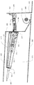
도 1은 실시예에 따라 차량에 장착되고 제어 케이블에 부착된 예시적인 도어 체크이다.
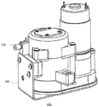
도 2는 본 개시내용의 양태들에 따른 액추에이터의 이미지이다.
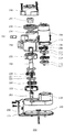
도 3 내지 도 4는 본 개시내용의 양태들에 따른 액추에이터의 내부 컴포넌트들의 분해 사시도이다.
도 5는 본 개시내용의 양태들에 따른 리셋 위치에 있는 액추에이터의 단면도이다.
도 6 내지 도 7은 본 개시내용의 양태들에 따라 풀리에 맞물리는 액추에이터의 허브의 단면도들이다.
도 8은 본 개시내용의 양태들에 따른 부분적으로 열린 구성의 도어 체크의 이미지이다.
도 9는 본 개시내용의 양태들에 따른 풀리와 맞물리는 액추에이터의 허브의 단면도이다.
도 10은 본 개시내용의 양태들에 따른 닫힌 구성의 도어 체크의 이미지이다.
도 11 및 도 12는 본 개시내용의 양태들에 따른, 도어가 수동으로 동작되고 있는 동안의 액추에이터의 단면도들이다.
도 13 내지 도 14는 본 개시내용의 양태들에 따른 허브, 풀리 및 마찰판의 사시도들이다.
도 15 및 도 16은 본 개시내용의 양태들에 따른 풀리와 맞물리는 허브의 이미지들이다.
도 17은 실시예에 따른 시스템의 기능도이다.
도 18은 본 개시내용의 양태들에 따른 도어 각도 센서의 사시도이다.
도 19는 본 개시내용의 양태들에 따른 모터 각도 센서의 사시도이다.
도 20a 및 도 20b는 본 개시내용의 양태들에 따른 과부하 해제부의 단면도이다.
도 21a 및 도 21b는 도어를 닫기 위한 시스템을 포함하는 차량의 도면들이다.
도 22는 실시예에 따른 흐름도이다.The techniques of the present invention are illustrated by way of example and not by way of limitation in the figures of the accompanying drawings, in which like reference numerals refer to like elements.
1 is an exemplary door check mounted on a vehicle and attached to a control cable according to an embodiment.
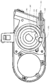
2 is an image of an actuator according to aspects of the present disclosure;
Figures 3-4 are exploded perspective views of internal components of the actuator in accordance with aspects of the present disclosure.
5 is a cross-sectional view of an actuator in a reset position in accordance with aspects of the present disclosure;
Figures 6-7 are cross-sectional views of a hub of an actuator engaged with a pulley in accordance with aspects of the present disclosure;
8 is an image of a door check of a partially open configuration in accordance with aspects of the present disclosure;
9 is a cross-sectional view of a hub of an actuator engaged with a pulley in accordance with aspects of the present disclosure;
10 is an image of a door check of a closed configuration in accordance with aspects of the present disclosure;
11 and 12 are cross-sectional views of the actuator while the door is being manually operated, in accordance with aspects of the present disclosure.
Figures 13-14 are perspective views of hubs, pulleys, and friction plates in accordance with aspects of the present disclosure.
Figures 15 and 16 are images of a hub that engages a pulley in accordance with aspects of the present disclosure.
17 is a functional diagram of the system according to the embodiment.
18 is a perspective view of a door angle sensor in accordance with aspects of the present disclosure;
19 is a perspective view of a motor angle sensor in accordance with aspects of the present disclosure;
20A and 20B are cross-sectional views of an overload release portion according to aspects of the present disclosure;
Figures 21A and 21B are views of a vehicle including a system for closing a door.
22 is a flowchart according to an embodiment.
개요summary
본 기술은 도어를 자동으로 당겨 닫음으로써 차량 도어의 폐쇄를 돕는 것에 관한 것이다. 예를 들어, 차량 내의 컴퓨팅 디바이스들은 차량 도어가 열린 채로 남겨졌거나 부분적으로만 닫혀있음을 결정할 수 있다. 이 경우, 컴퓨팅 디바이스들은 액추에이터를 트리거링하여, 차량의 몸체와 차량 도어 사이에 연결된 도어 체크에 부착된 제어 케이블을 당기게 할 수 있다. 제어 케이블의 견인력에 종속될 때, 도어 체크는 폐쇄 상태로 강제될 수 있고, 그에 의해 도어가 완전히 닫히게 할 수 있다.This technique relates to helping to close a vehicle door by automatically pulling the door closed. For example, computing devices in a vehicle can determine that the vehicle door is left open or partially closed. In this case, the computing devices may trigger the actuator to pull the control cable attached to the door check connected between the vehicle body and the vehicle door. When subject to the traction force of the control cable, the door check can be forced into the closed state, thereby making the door completely closed.
차량 도어들은 하나 이상의 힌지 및 도어 체크의 사용에 의해 차량의 몸체에 장착될 수 있다. 예를 들어, 차량의 조수석 도어와 같은 도어가 힌지에 의해 차량의 몸체에 부착될 수 있다. 힌지는 도어가 힌지 둘레의 회전의 축 상에서, 폐쇄 또는 개방 위치와 그것들 사이의 중간 위치들 사이를 자유롭게 움직일 수 있도록 한다. 일부 실시예들에서, 차량의 몸체에 도어를 장착하기 위해, 하나보다 많은 힌지가 사용될 수 있다.The vehicle doors may be mounted to the body of the vehicle by use of one or more hinges and door checks. For example, a door such as a passenger seat door of a vehicle may be attached to the vehicle body by a hinge. The hinge allows the door to freely move between closed or open positions and intermediate positions therebetween, on the axis of rotation about the hinge. In some embodiments, more than one hinge may be used to mount the door to the vehicle body.
하나 이상의 도어 체크는 힌지 둘레의 회전의 축 상에서 도어의 이동 범위를 제한하기 위해 사용될 수 있다. 도어 체크는 제1 단부 및 제2 단부를 포함할 수 있으며, 개방 상태, 폐쇄 상태 및 그것들 사이의 중간 상태들로 위치될 수 있다. 이와 관련하여, 개방, 폐쇄 및 중간 상태들은 각각 개방, 폐쇄, 및 중간 위치들에 있는 동안의 도어의 위치에 대응할 수 있다. 일부 실시예들에서, 힌지 및 도어 체크는 후드, 연료 탱크 커버, 트렁크 등과 같은, 차량의 도어 외의 컴포넌트들을 부착하기 위해 사용될 수 있다. 일부 실시예들에서, 도어, 후드, 연료 탱크 커버, 트렁크 등과 같은 컴포넌트들은 도어 체크, 힌지 및 다른 그러한 부착 방법들의 임의의 조합으로 차량에 부착될 수 있다.One or more door checks may be used to limit the range of movement of the door on the axis of rotation about the hinge. The door check may include a first end and a second end and may be positioned in an open state, a closed state, and intermediate states therebetween. In this regard, the open, closed and intermediate states may correspond to the position of the door during opening, closing, and intermediate positions, respectively. In some embodiments, the hinge and door check may be used to attach components other than the door of the vehicle, such as a hood, a fuel tank cover, a trunk, and the like. In some embodiments, components such as doors, hoods, fuel tank covers, trunks, etc. may be attached to the vehicle in any combination of door checks, hinges, and other such attachment methods.
도어 체크는 제어 케이블을 부착하기 위한 커넥터를 포함할 수 있다. 이와 관련하여, 커넥터는 도어의 내부에 위치된 도어 체크의 제1 단부에 부착될 수 있다. 보우덴 케이블(Bowden cable)과 같은 제어 케이블은 커넥터에 제거가능하게 또는 영구적으로 부착될 수 있다. 이와 관련하여, 제어 케이블은 용접, 매듭(knot), 나사, 아이 피팅(eye fitting), 클램프, 접착제 또는 다른 그러한 연결을 통해 커넥터에 연결될 수 있다. 일부 실시예들에서, 제어 케이블은 힌지 또는 컴포넌트(예를 들어, 도어, 후드, 연료 탱크 커버, 트렁크 등)에 영구적으로 또는 제거가능하게 부착될 수 있다.The door check may include a connector for attaching the control cable. In this connection, the connector can be attached to the first end of the door check located inside the door. A control cable, such as a Bowden cable, may be removably or permanently attached to the connector. In this regard, the control cable may be connected to the connector through welding, knots, screws, eye fittings, clamps, adhesives or other such connections. In some embodiments, the control cable may be permanently or removably attached to a hinge or component (e.g., a door, hood, fuel tank cover, trunk, etc.).
제어 케이블의 제2 단부는 액추에이터에 연결될 수 있다. 예를 들어, 액추에이터는 케이블 하우징을 통해 제어 케이블을 수용하고, 풀리 상의 슬롯 내에서 제어 케이블의 단부를 연결하도록 구성될 수 있다. 일부 실시예들에서, 액추에이터는 마운팅 브래킷으로 도어의 내부에 장착될 수 있다. 다른 실시예들에서, 액추에이터는 차량 도어에 근접한 위치에 장착될 수 있으며, 이에 의해 제어 케이블은 액추에이터에 의한 견인력에 종속될 수 있다.The second end of the control cable may be connected to an actuator. For example, the actuator may be configured to receive the control cable through the cable housing and to connect the end of the control cable within the slot on the pulley. In some embodiments, the actuator may be mounted within the door with a mounting bracket. In other embodiments, the actuator may be mounted at a location proximate the vehicle door, whereby the control cable may be subject to traction by the actuator.
액추에이터는 제어 케이블에 견인력을 제공함으로써 도어 체크를 폐쇄 상태에 배치하도록 구성될 수 있다. 이와 관련하여, 액추에이터는 모터의 회전력을 선형 힘으로 변환하도록 구성될 수 있다. 예를 들어, 액추에이터는 다수의 샤프트를 통해 기어들의 세트에 회전력을 제공하는 모터를 포함할 수 있다. 그러면, 기어들은 출력 회전력을 출력 샤프트에 제공할 수 있다. 일부 실시예들에서, 액추에이터는 모터에 의해 제공된 회전력을 출력 샤프트에 전달하기 위해, 다수의 기어 스테이지, 및 평 기어들(spur gears)의 하나 이상의 세트를 포함하는 파워 트레인(power train)을 포함할 수 있다.The actuator may be configured to place the door check in a closed state by providing a traction force on the control cable. In this connection, the actuator can be configured to convert the rotational force of the motor into a linear force. For example, an actuator may include a motor that provides rotational force to a set of gears through a plurality of shafts. Then, the gears can provide an output torque to the output shaft. In some embodiments, the actuator includes a power train comprising a plurality of gear stages, and one or more sets of spur gears, for transmitting the rotational force provided by the motor to the output shaft .
출력 샤프트는 허브에 연결될 수 있다. 액추에이터가 동작하고 있지 않을 때, 허브는 리셋 위치에 머무를 수 있다. 액추에이터 동작하고 있을 때, 허브는 풀리와 맞물리도록 제1 방향으로 회전할 수 있다. 이와 관련하여, 허브는 하나 이상의 외부 치형부를 포함할 수 있으며, 그러한 외부 치형부는 풀리 상의 하나 이상의 내부 치형부와 연동함으로써 풀리를 회전시킨다. 그러면, 제어 케이블이 풀리 둘레로 당겨질 수 있고, 그에 의해 제어 케이블이 액추에이터 내로 후퇴하게 한다. 그렇게 함으로써, 제어 케이블에 의해 도어 체크에 선형 힘이 가해질 수 있고, 그에 의해 도어가 닫히게 된다. 제어 케이블이 힌지 또는 컴포넌트에 직접 부착되는 실시예들에서, 선형 힘이 부착 지점에 가해지며, 그에 의해 힌지 또는 컴포넌트가 닫히게 한다.The output shaft can be connected to the hub. When the actuator is not operating, the hub may remain in the reset position. When the actuator is operating, the hub may rotate in a first direction to engage the pulley. In this regard, the hub may include one or more outer teeth, such that the outer teeth rotate in conjunction with one or more internal teeth on the pulley. The control cable can then be pulled around the pulley, thereby causing the control cable to retract into the actuator. By doing so, a linear force can be applied to the door check by the control cable, thereby closing the door. In embodiments in which the control cable is attached directly to the hinge or component, a linear force is applied to the attachment point, thereby causing the hinge or component to close.
액추에이터가 도어를 닫는 동작을 완료하면, 허브는 리셋 위치로 복귀할 수 있다. 예를 들어, 허브가 리셋 위치로 복귀할 때까지, 허브는 제1 방향에 반대되는 제2 방향으로 회전할 수 있다. 풀리는 허브가 리셋 위치로 복귀할 때 풀리를 제위치에 유지하고 제어 케이블에 대한 장력을 유지하는 하나 이상의 스프링에 연결될 수 있다.When the actuator completes closing the door, the hub can return to the reset position. For example, until the hub returns to the reset position, the hub may rotate in a second direction opposite to the first direction. The pulley can be connected to one or more springs that maintain the pulley in place and maintain tension on the control cable as the hub returns to the reset position.
액추에이터 및 제어 케이블은 도어를 수동으로 동작시키는 데 필요한 힘에 거의 영향을 주지 않도록 구성될 수 있다. 이와 관련하여, 풀리는 도어가 수동으로 개폐될 때 풀리 둘레에 제어 케이블을 감는 것을 돕는 하나 이상의 스프링에 연결될 수 있다. 예를 들어, 도어가 열릴 때, 제어 케이블은 도어 체크에 의해 당겨질 수 있고, 그에 의해 풀리가 제어 케이블을 풀어주는 방향으로 회전하게 한다. 도어가 닫힐 때, 도어가 열릴 때 스프링에 가해졌던 장력이 해제될 수 있고, 그에 의해 풀리가 풀리 둘레에서 제어 케이블을 역방향으로 회전시키게 된다.The actuator and control cable may be configured to have little effect on the force required to manually operate the door. In this regard, the pulley can be connected to one or more springs that help wrap the control cable around the pulley when the door is manually opened and closed. For example, when the door is opened, the control cable can be pulled by the door check, thereby causing the pulley to rotate in the direction to release the control cable. When the door is closed, the tension applied to the spring when the door is opened can be released, thereby causing the pulley to rotate the control cable in the opposite direction around the pulley.
액추에이터의 일부 실시예들에서, 허브는 래칫(ratchet)의 일부로서 구현될 수 있다. 예를 들어, 허브는 풀리 상의 하나 이상의 치형부와 맞물릴 수 있는 하나 이상의 폴을 포함할 수 있다. 하나 이상의 폴을 맞물리게 하기 위해, 마찰 디스크는 허브가 회전할 때 하나 이상의 폴이 허브 상의 컷 아웃들로부터 풀리 상의 하나 이상의 치형부 내로 확장하게 할 수 있다. 이와 관련하여, 마찰 패드가 허브 상으로 밀려 내려갈 수 있다. 래칫이 회전할 때, 하나 이상의 폴은 마찰 패드로부터의 마찰력에 종속될 수 있고, 그에 의해 하나 이상의 폴이 외향 위치로 확장하게 할 수 있다. 허브가 리셋 위치로 복귀할 때, 하나 이상의 폴은 반대 방향으로의 마찰력에 종속될 수 있고, 그에 의해, 도 16에 보여진 바와 같이 하나 이상의 폴이 후퇴하게 한다. 풀리는 마찰 패드에 의한 마찰력에 종속되지 않을 때 어느 방향으로든 자유롭게 회전할 수 있다.In some embodiments of the actuator, the hub may be implemented as part of a ratchet. For example, the hub may include one or more pawls that can engage one or more teeth on the pulley. To engage one or more of the pawls, the friction disk may cause one or more pawls to expand into the at least one tooth on the pulley from the cutouts on the hub as the hub rotates. In this regard, the friction pad can be pushed down onto the hub. As the ratchet rotates, one or more pawls may be subject to frictional forces from the friction pads, thereby causing one or more of the pawls to expand into an outward position. When the hub returns to the reset position, one or more of the pawls may be subject to a frictional force in the opposite direction, thereby causing one or more of the pawls to retract, as shown in FIG. The pulleys can freely rotate in any direction when they are not subject to frictional forces by the friction pads.
차량 내의 컴퓨팅 디바이스들은 차량의 도어가 열린 채로 남겨졌거나 중간 위치에 있다고 결정할 수 있다. 이와 관련하여, 차량은 복수의 센서를 포함할 수 있는 도어 보조 시스템을 포함하는 매우 정교한 차량용 컴퓨터 시스템을 가질 수 있다. 복수의 센서로부터의 데이터는 도어가 열렸는지 또는 닫혔는지를 검출하기 위해 실시간으로 차량의 중앙 프로세서에 의해 수신되고 처리될 수 있다. 도어 보조 시스템이 도어가 열려 있음을 검출할 때, 트리거링 신호가 액추에이터로 송신되어 액추에이터가 도어를 닫게 할 수 있다.Computing devices in the vehicle may determine that the door of the vehicle is left open or in an intermediate position. In this regard, the vehicle may have a highly sophisticated vehicle computer system including a door assistance system that may include a plurality of sensors. Data from the plurality of sensors can be received and processed by the central processor of the vehicle in real time to detect whether the door is open or closed. When the door assist system detects that the door is open, a triggering signal may be sent to the actuator to cause the actuator to close the door.
일부 실시예들에서, 액추에이터는 과도한 힘이 제어 케이블에 전달되는 것을 방지하기 위해 과부하 해제부(overload release)를 포함할 수 있다. 예를 들어, 링 기어가 기어 세트들 중 하나의 주위에 배치될 수 있다. 링 기어의 외부는 테이퍼링된 폴이 위치될 수 있는 복수의 노치를 포함할 수 있다. 링 기어가 기어 세트로부터의 과도한 힘에 종속될 때, 테이퍼링된 폴은 하나 이상의 노치 중 하나로부터 해제될 수 있고, 그에 의해 링 기어가 기어 세트의 반대 방향으로 회전하는 것을 허용한다. 힘의 양이 감소될 때, 테이퍼링된 폴에 부착된 스프링은 테이퍼링된 폴을 하나 이상의 노치 중 하나에 밀어 넣을 수 있다.In some embodiments, the actuator may include an overload release to prevent excessive force from being transmitted to the control cable. For example, a ring gear may be placed around one of the gear sets. The exterior of the ring gear may include a plurality of notches through which the tapered pawls may be located. When the ring gear is subjected to excessive force from the gear set, the tapered pawl can be released from one of the one or more notches, thereby allowing the ring gear to rotate in the opposite direction of the gear set. When the amount of force is reduced, a spring attached to the tapered pawl may push the tapered pawl into one of the one or more notches.
본 명세서에서 설명된 특징들은 자율 주행 차량이 승객이 차량을 떠나면서 완전하게 닫지 않은 도어를 자동으로 닫는 것을 허용할 수 있다. 이렇게 함으로써, 개인이 도어를 수동으로 닫을 필요없이 자율 주행 차량은 동작을 계속할 수 있다. 추가로, 이러한 특징들은 차량이 운전될 수 있기 전에 차량의 모든 도어가 완전히 닫힐 것을 보장하기 위해, 자율 주행 및 비-자율 주행 차량 둘 다에서 사용될 수 있다.The features described herein may allow an autonomous vehicle to automatically close a door that is not completely closed as the passenger leaves the vehicle. By doing so, the autonomous vehicle can continue to operate without the need for an individual to manually close the door. Additionally, these features may be used in both autonomous and non-autonomous vehicles to ensure that all doors of the vehicle are fully closed before the vehicle can be operated.
예시적인 시스템An exemplary system
본 개시내용의 특정 양태들은 자율 주행 차량들과 관련하여 특히 유용하지만, 차량은 자동차, 트럭, 버스, 보트, 항공기, 헬리콥터, 레크리에이션 차량, 놀이 공원 차량, 농장 장비, 건설 장비, 트램, 골프 카트, 열차, 및 트롤리, 또는 아래에서 더 상세하게 논의되는 바와 같은 도어들을 이용하는 임의의 차량을 포함하지만 그에 한정되지는 않는 임의의 유형의 차량일 수 있다.Certain aspects of the present disclosure are particularly useful with respect to autonomous vehicles, but the vehicle may be used in a variety of applications including automobiles, trucks, buses, boats, aircraft, helicopters, recreational vehicles, amusement park vehicles, farm equipment, construction equipment, trams, A car, a train, and a trolley, or any vehicle that uses doors such as those discussed in more detail below.
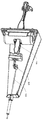
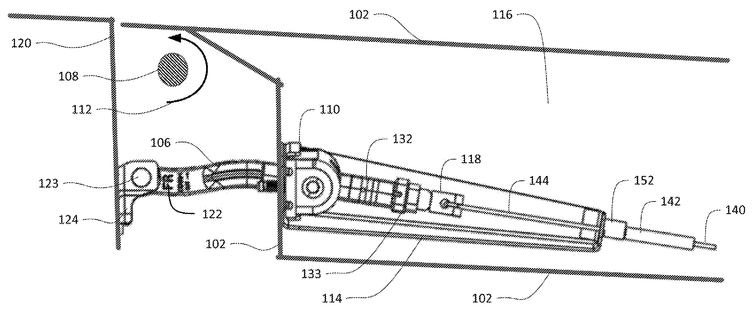
차량 도어들은 하나 이상의 힌지 및 도어 체크의 사용에 의해 차량의 몸체에 장착될 수 있다. 예를 들어, 차량의 조수석 도어와 같은 도어(102)는 도 1에 보여진 바와 같이 힌지(108)에 의해 차량(120)의 몸체에 부착될 수 있다. 이와 관련하여, 힌지(108)는 도어가 힌지(108) 둘레의 회전의 축[화살표(112)로 표현되는 회전의 축) 상에서, 개방 또는 폐쇄 위치와 이들 사이의 중간 위치들 사이를 자유롭게 움직이는 것을 허용한다. 일부 실시예들에서, 차량(120)의 몸체에 도어(102)를 장착하기 위해, 하나보다 많은 힌지가 사용될 수 있다.The vehicle doors may be mounted to the body of the vehicle by use of one or more hinges and door checks. For example, a
하나 이상의 도어 체크는 힌지 둘레의 회전의 축 상에서 도어의 이동의 범위를 제한하는 데 사용될 수 있다. 예를 들어, 도어 체크(106)는 도 1에 도시된 바와 같이 차량(120)의 몸체 및 도어(116)의 내부에 연결될 수 있다. 이와 관련하여, 도어 체크(106)는 제1 단부(132) 및 제2 단부(122)를 포함할 수 있다. 제2 단부(122)는 회전가능한 연결 지점(123)을 통해 마운팅 포스트(124)에 연결될 수 있다. 따라서, 도어 체크(106)는 연결 지점(123) 둘레를 회전할 수 있고, 개방, 폐쇄, 및 그들 사이의 중간 상태들 내에 위치될 수 있다. 이러한 개방, 폐쇄, 및 중간 상태들은 각각 개방, 폐쇄, 및 중간 위치들에 있는 동안의 도어(102)의 위치에 대응할 수 있다.One or more door checks may be used to limit the range of movement of the door on the axis of rotation about the hinge. For example, the door check 106 may be connected to the body of the
도어 체크의 개방 상태는 도어 체크 상에 위치된 스토퍼에 의해 설정될 수 있다. 예를 들어, 도 1에 보여진 바와 같이, 도어 체크의 제1 단부(132)는 스토퍼(133)를 포함할 수 있다. 도어 체크(106)가 연결 지점(123) 둘레를 회전할 때, 도어 체크(106)는 도어 가이드(110)를 통해 슬라이딩할 수 있다. 개방 상태에 있을 때, 스토퍼(133)는 도어 가이드(110)에 접촉할 수 있고, 그에 의해 도어 체크(106)가 연결 지점(123) 둘레에서 더 회전하는 것을 정지시킬 수 있다. 일부 실시예들에서, 힌지(108) 및 도어 체크(106)는 차량의 도어 이외의 컴포넌트들, 예컨대 후드, 연료 탱크 커버, 트렁크 등을 부착하기 위해 사용될 수 있다.The open state of the door check can be set by the stopper positioned on the door check. For example, as shown in FIG. 1, the
도어 체크는 제어 케이블을 부착하기 위한 커넥터 및 마운트를 포함할 수 있다. 이와 관련하여, 커넥터(118)는 도 1에 보여진 바와 같이 도어(116)의 내부에 위치된 도어 체크(132)의 제1 단부에 부착될 수 있다. 커넥터(118)는 도어 체크(106)에 용접되거나, 나사 결합되거나, 접착되거나, 다르게 부착될 수 있다. 일부 경우들에서, 커넥터(118)는 도어 체크(106) 상에 일체로 형성될 수 있다. 마운트(114)는 도어 체크(106)를 도어(102)에 유지시키는 볼트들과 같은 기존의 연결 지점들을 사용하여 기존 도어 체크 주위에 개장될(retrofitted) 수 있거나, 도어 체크의 일체형 컴포넌트로서 형성될 수 있다.The door check may include a connector and a mount for attaching the control cable. In this regard, the
도어 체크에는 제어 케이블이 부착될 수 있다. 예를 들어, 외부 하우징(142)을 구성하는 보우덴 케이블, 및 외부 하우징 내에 위치된 내부 케이블(144)과 같은 제어 케이블(140)은 도 1에 보여진 바와 같이 마운트(114) 및 커넥터(118)에 부착될 수 있다. 이와 관련하여, 마운트(114)는 제어 케이블(140)의 제1 단부의 외부 하우징(142)이 삽입될 수 있는 부착 지점(152)을 포함할 수 있다. 제어 케이블(140)의 외부 하우징(142)은 마운트(114)의 부착 지점(152)에 제거가능하게 또는 영구적으로 부착될 수 있다. 대안적으로, 외부 하우징(142)은 마운트(114)에 직접 부착될 수 있다. 일부 실시예들에서, 제어 케이블을 대신하여, 벨트 또는 링크 체인이 사용될 수 있다.A control cable can be attached to the door check. For example, a
제어 케이블의 내부 케이블은 커넥터에 부착될 수 있다. 이와 관련하여, 제어 케이블(140)의 내부 케이블(144)은 용접, 니플 연결(nipple connection), 매듭, 나사, 아이 피팅, 클램프, 접착제 또는 다른 그러한 연결을 통해 커넥터에 연결될 수 있다. 이와 같이, 제어 케이블(140)이 도어 체크(106)에 힘을 가하면, 내부 케이블(144)에 의해 도어 체크(132)의 제1 단부에 힘이 가해지고, 외부 하우징(142)에 의해 생성된 힘은 마운트(114)에 의해 저항될 수 있다. 이와 같이, 도어(102)를 통해 전달되는 최소한의 힘이 존재한다.The internal cable of the control cable can be attached to the connector. In this regard, the
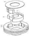
제어 케이블의 제2 단부는 액추에이터에 연결될 수 있다. 예를 들어, 도 2에 보여진 액추에이터와 같은 액추에이터(202)는 케이블 하우징(236)을 통해 제어 케이블을 수용하고 제어 케이블의 단부를 풀리(도시되지 않음) 상의 슬롯 내에 연결하도록 구성될 수 있다. 본 명세서에 더 설명되는 바와 같이, 케이블 하우징(236)은 내부 케이블(144)이 액추에이터(202)의 내부로 통과하여 풀리에 부착되는 것을 허용하면서, 제어 케이블(140)의 외부 하우징(142)을 영구적으로 또는 제거가능하게 고정할 수 있다. 일부 실시예들에서, 외부 하우징(142)은 내부 케이블(144)의 일부 또는 전부를 마운트(114)로부터 케이블 하우징(236)까지 덮을 수 있다. 일부 실시예들에서, 액추에이터는 마운팅 브래킷(250)으로 도어(102)의 내부에 장착될 수 있다. 다른 실시예들에서, 액추에이터는 차량 도어에 근접한 위치에 장착될 수 있고, 그에 의해 제어 케이블은 액추에이터에 의한 견인력에 종속될 수 있다.The second end of the control cable may be connected to an actuator. For example, an
액추에이터(202)가 제어 케이블(140)에 힘을 가하면, 힘은 내부 케이블(144)에 가해지고 마운팅 브래킷(250)에 의해 저항된다. 이와 같이, 도어(102)를 닫는 힘은 액추에이터(202) 내에 담겨지고, 도어(102)를 통해서는 힘이 거의 또는 전혀 전달되지 않는다.When the
액추에이터는 제어 케이블 상에 견인력을 제공함으로써 도어 체크를 폐쇄 상태로 배치하도록 구성될 수 있다. 이와 관련하여, 액추에이터는 모터의 회전력을 선형 힘으로 변환하도록 구성될 수 있다. 예를 들면, 도 3 및 도 4에 도시된 바와 같이, 액추에이터(202)는 다수의 샤프트를 통해 기어들의 세트에 회전력을 제공하는 모터(204)를 포함할 수 있다. 그러면 기어들은 출력 회전력을 출력 샤프트에 제공할 수 있다. 일부 실시예들에서, 모터는 분당 4000회전(RPM), 또는 그 이상 또는 이하로 동작할 수 있다.The actuator may be configured to place the door check in a closed state by providing a traction force on the control cable. In this connection, the actuator can be configured to convert the rotational force of the motor into a linear force. For example, as shown in Figures 3 and 4, the
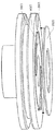
액추에이터는 모터(204)에 의해 제공된 회전력을 출력 샤프트에 전달하기 위해, 다수의 기어 스테이지 및 평 기어들의 세트를 갖는 파워 트레인을 포함할 수 있다. 도 3 및 도 4의 액추에이터(202)의 분해도에 더 보여진 바와 같이, 기어 스테이지들 및 평 기어들의 세트는 기어 박스들(218 및 234)과 같은 하나 이상의 기어 박스 내에 위치될 수 있다.The actuator may include a powertrain having a plurality of gear stages and a set of spur gears for transmitting the rotational force provided by the
모터(204)의 출력은 제1 중앙 기어(213)를 통해 제2 기어 세트(214)에 연결된 제1 기어 세트(208)에 연결될 수 있다. 제2 기어 세트(214)는 제1 샤프트(217)를 통해 제1 평 기어(220)에 연결될 수 있다. 예를 들어, 모터와 제1 기어 세트 사이의 기어 비는 6:1, 또는 그 이상 또는 이하일 수 있고, 제1 기어 세트와 제2 기어 세트 사이의 기어 비는 6:1, 또는 그 이상 또는 이하일 수 있다.The output of the
파워 트레인은 상기 제1 평 기어(220)에 의해 발생된 회전력을 수용하기 위한 제2 평 기어(221)를 더 포함할 수 있다. 일부 실시예들에서, 제1 평 기어(220)와 제2 평 기어(221)의 기어 비는 1:1, 또는 그 이상 또는 이하이다. 다음으로, 제2 평 기어(221)는 제3 및 제4 기어 세트(각각 224 및 228)를 구동할 수 있고, 이어서도 3 및 도 4에 더 보여진 바와 같이 출력 샤프트(230)를 구동할 수 있다. 예를 들어, 제2 평 기어(221)는 제3 기어 세트(224)를 구동하기 위한 제3 중앙 기어를 포함할 수 있는 피니언(pinion)(252)을 통해 제3 기어 세트(224)에 연결될 수 있다. 제3 기어 세트(224)는 제4 중앙 기어(227)를 통해 제4 기어 세트(228)에 연결된다. 제4 기어 세트(228)는 출력 샤프트(230)에 연결될 수 있다. 제2 평 기어(221)와 제3 기어 세트(224) 사이의 기어 비는 1:1, 또는 그 이상 또는 이하일 수 있다. 제3 기어 세트와 제4 기어 세트 사이의 기어 비는 6:1, 또는 그 이상 또는 이하일 수 있다. 제4 기어 세트와 출력 샤프트 사이의 기어 비는 6:1, 또는 그 이상 또는 이하일 수 있다. 이와 같이, 출력 샤프트는 분당 3 회전(RPM), 또는 그 이상 또는 이하로 동작할 수 있다.The power train may further include a
각각의 기어 스테이지는 중앙 기어, 유성 기어(planet gear) 및 외부 링 기어를 포함하는 유성 기어링(epicyclic gearing)으로 구성될 수 있다. 예를 들어, 도 3에 보여진 바와 같이, 제1 기어 스테이지는 제1 기어 세트(208)(즉, 유성 기어들)를 포함할 수 있다. 제1 기어 세트(208)는 그 베이스에 제1 중앙 기어(213)를 가질 수 있는 캐리어(212) 상에 위치될 수 있다. 링 기어(도시되지 않음)는 기어 박스(218) 내에 또는 모터(204)의 하부 하우징(210)에 위치될 수 있다. 모터 샤프트(도시되지 않음)는 모터(204)가 작동될 때 제1 방향으로 회전할 수 있는 중앙 기어(206)를 포함할 수 있다. 중앙 기어는 제1 기어 세트(208)가 링 기어 둘레에서 반대의 제2 방향으로 회전하게 할 수 있다. 제1 기어 세트(208)의 회전들은 캐리어(212)가 제1 방향으로 회전하게 할 수 있고, 그에 의해 제1 중앙 기어(213)가 또한 제1 방향으로 회전하게 한다. 일부 실시예들에서, 4개, 또는 그 이상 또는 이하의 기어 스테이지가 사용될 수 있다.Each gear stage may be comprised of an epicyclic gearing including a center gear, a planet gear and an outer ring gear. For example, as shown in FIG. 3, the first gear stage may include a first gear set 208 (i.e., planetary gears). The first gear set 208 may be located on a
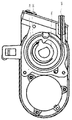
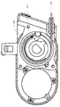
출력 샤프트(230)는 허브에 연결될 수 있다. 예를 들면, 도 3 및 도 4에 보여진 바와 같이, 허브(244)는 풀리(240) 및 하나 이상의 스프링(238) 내에 위치될 수 있다. 허브(244), 풀리(240), 및 하나 이상의 스프링(238)은 하우징(246) 내에 둘러싸일 수 있다. 출력 샤프트(230)는 허브(244) 내에 삽입될 수 있고, 그에 의해 액추에이터(202)가 허브(244)를 회전시킬 수 있게 한다.The
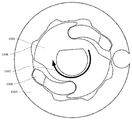
허브는 하나 이상의 외부 치형부를 포함할 수 있다. 예를 들어, 도 5에 보여진 바와 같이, 허브(244)는 풀리(240) 상의 내부 치형부(540)와 같은 하나 이상의 내부 치형부와 연동함으로써 풀리(240)를 회전시킬 수 있는 치형부(544)와 같은 하나 이상의 치형부를 포함할 수 있다. 케이블 부착 지점(510)에서 풀리에 부착된 내부 케이블(144)의 제2 단부는 풀리 둘레로 당겨질 수 있고, 그에 의해 제어 케이블의 내부 케이블(144)이 액추에이터 내로 후퇴하게 할 수 있다. 이렇게 함으로써, 제어 케이블(140)에 의해 도어 체크(106)에 선형 힘이 가해질 수 있고, 그에 의해 도어가 닫히게 한다. 일부 실시예들에서, 내부 케이블(144)의 제2 단부는 용접, 니플 연결, 매듭, 나사, 아이 피팅, 클램프, 접착제, 또는 다른 그러한 연결을 통해 풀리에 제거가능하게 또는 영구적으로 부착될 수 있다. 일부 실시예들에서, 드럼 또는 크랭크 아암은 풀리 대신에 사용될 수 있다.The hub may include one or more external teeth. 5, the
허브는 액추에이터가 작동하고 있지 않을 때 리셋 위치에 머무를 수 있다. 예를 들어, 도 5에 보여진 바와 같이, 리셋 위치에 있을 때, 허브(244)의 치형부(544)는 풀리의 내부 치형부(540)로부터 맞물림 해제된 채로 남아있는다. 이와 같이, 리셋 위치에 있는 동안, 액추에이터(202)에 의해 제어 케이블(140) 상에 어떠한 힘도 가해지지 않는다.The hub can remain in the reset position when the actuator is not operating. For example, as shown in FIG. 5, when in the reset position, the
도어(102)가 개방되거나 중간 위치에 배치될 때, 풀리의 위치가 조절될 수 있다. 이와 관련하여, 도어(102)가 개방되거나 중간 위치에 배치될 때, 도어 체크(106)는 커넥터(118)에 연결된 내부 케이블(140)의 제1 단부를 당길 수 있다. 그러면, 도어 체크(106)의 커넥터(118)가 내부 케이블(144)의 제1 단부에 견인력을 제공함에 따라, 제어 케이블(140)은 풀리(240)를 회전시킬 수 있고, 그에 의해 케이블 부착 지점(510)에서 풀리(240)에 견인력을 제공한다. 이와 같이, 내부 케이블(144)은 풀리(240)가 도어의 위치에 대응하는 위치들로 회전하는 동안 액추에이터(202)의 내부로부터 부분적으로 해제된다.When the
액추에이터가 작동하고 있을 때, 허브는 풀리와 맞물리도록 제1 방향으로 회전할 수 있다. 예를 들어, 도 6에 보여진 바와 같이, 액추에이터가 작동될 때, 허브(244)는 화살표(602)에 의해 표시된 제1 방향으로 회전할 수 있다. 허브(244)가 회전함에 따라, 허브(244)의 치형부(544)는 풀리(240)의 내부 치형부(540)와 맞물릴 수 있다.When the actuator is in operation, the hub may rotate in a first direction to engage the pulley. For example, as shown in FIG. 6, when the actuator is actuated,
허브가 회전함에 따라, 내부 케이블은 액추에이터 내로 후퇴할 수 있다. 이와 관련하여, 허브(244)가 회전함에 따라, 치형부가 서로 접촉하고 나면, 풀리(240)는 도 5, 도 6 및 도 7 사이에서 볼 수 있는 바와 같이 대응 거리만큼 회전할 수 있다. 즉, 일단 치형부(544)가 내부 치형부(544)와 맞물리고 나면, 풀리(240)는 허브(244)와 동일한 각도 거리만큼 회전할 수 있고, 그에 의해 연결 지점(510)이 풀리와 함께 회전함에 따라 내부 케이블(144)의 제2 단부가 풀리(240) 둘레에 감기게 할 수 있다.As the hub rotates, the inner cable can retract into the actuator. In this regard, as the
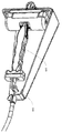
허브가 풀리를 회전시킴에 따라, 선형 힘이 제어 케이블에 의해 도어 체크에 가해질 수 있다. 이와 관련하여, 내부 케이블(144)의 제2 단부가 풀리(240) 둘레에 감겨짐에 따라, 도 8에 보여진 바와 같이 커넥터(118)에서 내부 케이블(144)의 제1 단부에 의해 견인력이 도어 체크(106)에 견인력이 가해진다. 견인력이 도어 체크(106)에 가해짐에 따라, 도어 체크(106)는 중간 상태들을 통해 폐쇄 상태를 향해 당겨진다. 예를 들어, 도 8에 보여진 바와 같이, 도어 체크(106)는 도어의 중간 위치에 연관된 중간 위치에 있다.As the hub rotates the pulley, a linear force can be applied to the door check by the control cable. In this regard, as the second end of the
제어 케이블은 도어 체크가 도어를 닫게 할 수 있다. 이와 관련하여, 허브(244)와 맞물린 풀리(240)는 내부 케이블(144)이 도 9의 화살표(602)에 의해 보여진 제1 방향으로 풀리(240) 둘레로 미리 결정된 거리만큼 회전되게 할 수 있다. 미리 결정된 거리는 270도, 또는 그 이상 또는 이하이다. 내부 케이블(144)의 제2 단부가 미리 결정된 거리를 회전하면, 도어 체크(106) 상에서 내부 케이블(144)의 제1 단부에서 발생된 힘은 도 10에 보여진 바와 같이 도어 체크를 폐쇄 상태로 배치하기에 충분할 수 있다. 이와 같이, 도어(102)는 폐쇄 상태에 대응하는 폐쇄 위치로 강제될 것이다.The control cable allows the door check to close the door. In this regard, the
액추에이터가 도어를 닫는 동작을 완료하면, 허브는 리셋 위치로 복귀할 수 있다. 예를 들어, 도 5에 보여진 바와 같이 허브가 리셋 위치로 복귀할 때까지, 허브는 제1 방향의 반대인 제2 방향으로 회전할 수 있다. 풀리는 하나 이상의 클럭 스프링과 같은 하나 이상의 스프링(238)에 연결될 수 있고, 이러한 스프링은 허브(244)가 리셋 위치로 복귀할 때 풀리(240)를 제위치에 고정시키고 제어 케이블(140)에 장력을 유지한다.When the actuator completes closing the door, the hub can return to the reset position. For example, until the hub returns to the reset position, as shown in FIG. 5, the hub may rotate in a second direction opposite to the first direction. The pulley may be coupled to one or
액추에이터 및 제어 케이블은 도어를 수동으로 동작시키는 데 필요한 힘에 거의 영향을 미치지 않도록 구성될 수 있다. 이와 관련하여, 풀리는 하나 이상의 스프링(238)에 연결될 수 있으며, 그러한 스프링들은 도 11 및 도 12에 각각 보여진 바와 같이 도어가 수동으로 열리고 닫힐 때 각각 제어 케이블을 풀리 둘레에서 풀거나 감는 것을 돕는다. 예를 들어, 도어가 수동으로 열릴 때, 내부 케이블(144)의 제1 단부는 도어 체크(106)에 의해 당겨질 수 있으며, 그에 의해 내부 케이블(144)의 제2 단부가 도 11에 보여진 바와 화살표(1102)에 보여진 제2 방향으로 풀리(240)를 회전시키게 한다. 풀리(240)가 화살표(1102)에 의해 보여진 제2 방향으로 회전됨에 따라, 내부 케이블(144)이 액추에이터(240)로부터 풀리면서 하나 이상의 스프링(238)이 장력 하에 놓일 수 있다.The actuator and control cable may be configured so as to have little effect on the force required to manually operate the door. In this regard, the pulleys may be connected to one or
내부 케이블은 도어가 수동으로 닫힐 때 풀리 둘레에 감겨질 수 있다. 예를 들어, 도어(102)가 수동으로 닫힐 때, 도어 체크(106)는 중간 상태들을 통해 폐쇄 상태로 이동할 수 있고, 그에 의해 하나 이상의 스프링(238)에 의해 풀리(240)에 가해진 인장력을 야기한 제1 단부로부터의 인장력을 해제하여, 도 12에 보여진 바와 같이 풀리(240)가 화살표(602)에 의해 보여진 제1 방향으로 회전하게 한다. 도어가 폐쇄 위치에 도달할 때까지 풀리가 회전하여 내부 케이블(144)을 그 둘레에 감는 동안, 하나 이상의 스프링(238)은 풀리(240) 상에 장력을 유지할 수 있다.The inner cable can be wrapped around the pulley when the door is manually closed. For example, when the
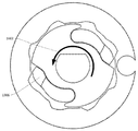
액추에이터의 일부 실시예들에서, 허브는 래칫의 일부로서 구현될 수 있다. 예를 들어, 도 13에 보여진 바와 같이, 래칫 허브(1302)는 도 5의 허브(244)와 비교될 수 있는 하나 이상의 폴(1306)을 포함할 수 있다. 하나 이상의 폴(1306)은 래칫 허브(1302) 상의 컷아웃들 내에 위치될 수 있다. 하나 이상의 폴(1306)은 마찰 디스크(1310)가 하나 이상의 폴(1306)에 압력을 가하는 것에 응답하여, 도 3의 풀리(240)에 비교될 수 있는 래칫 풀리(1304) 상의 하나 이상의 치형부(1308)와 맞물릴 수 있다.In some embodiments of the actuator, the hub may be implemented as part of a ratchet. For example, as shown in FIG. 13, the
하나 이상의 폴에 맞물리기 위해, 마찰 디스크는 래칫 허브가 회전할 때 하나 이상의 폴이 래칫 풀리 상의 하나 이상의 치형부 내로 확장하게 할 수 있다. 예를 들면, 도 14에 보여진 바와 같이, 마찰 디스크(1310)는 래칫 허브(1302) 상으로 하향 방향으로 눌러질 수 있다. 도 15에 보여진 바와 같이, 래칫 허브(1302)가 화살표(1502)에 의해 보여진 맞물림 방향으로 회전할 때, 하나 이상의 폴(1306)은 제1 방향(1502)으로 마찰 디스크로부터 마찰력에 종속될 수 있고, 그에 의해 하나 이상의 폴(1306)이 하나 이상의 치형부(1308) 내로 외향 위치(outwards position)까지 확장하게 할 수 있다. 도 16에 보여진 바와 같이, 래칫 허브가 리셋 위치에 복귀할 때, 하나 이상의 폴(1306)은 제1 방향(1502)의 마찰력의 반대 방향으로 화살표(1602)에 의해 보여진 제2 마찰력에 종속될 수 있고, 그에 의해 하나 이상의 폴(1306)이 래칫 허브(1302) 상의 컷아웃들 내로 후퇴하게 한다. 래칫 풀리(1304)는 마찰 패드에 의한 마찰력에 종속되지 않을 때 어느 방향으로든 자유롭게 회전할 수 있다.To engage one or more pawls, the friction disc may allow one or more pawls to expand into one or more teeth on the ratchet pulley as the ratchet hub rotates. For example, as shown in FIG. 14, the
래칫 허브는 하나 이상의 폴이 후퇴하고 나면 어느 임의적 위치에서든 리셋될 수 있다. 이와 같이, 래칫 허브의 리셋 위치는 제1 방향(1502)과 반대인 제2 방향으로 5도, 또는 그 이상 또는 이하와 같이, 단지 몇 도일 수 있다. 따라서, 도어는 허브(244)가 사용될 때보다 더 짧은 리셋 지연으로 수동 동작될 수 있다. 또한, 하나 이상의 치형부(1308)가 래칫 풀리(1304) 둘레에 패턴으로 배열되면, 도어 폐쇄의 재맞물림 및 개시는 래칫 허브 상의 하나 이상의 폴(1306)이 풀리 상의 하나 이상의 치형부(1308)와 맞물리도록 회전하기 위한 잠재적으로 적은 지연을 갖고서, 임의의 도어 위치로부터 발생할 수 있다.The ratchet hub may be reset at any arbitrary position once more than one pole has been retracted. As such, the reset position of the ratchet hub may be only a few degrees, such as 5 degrees in a second direction opposite to the
차량 내의 컴퓨터들 또는 컴퓨팅 디바이스들은 차량의 도어가 열린 채로 남겨졌거나 중간 위치에 있는 것으로 결정할 수 있다. 이와 관련하여, 차량은 복수의 센서를 포함할 수 있는 도어 보조 시스템을 포함하는 고도로 정교한 차량용 컴퓨터 시스템을 가질 수 있다. 예를 들어, 도 17에 보여진 바와 같이, 본 개시내용의 일 양태에 따른 드라이빙 시스템(1710)은 다양한 컴포넌트를 갖는 차량(1701)을 포함한다. 차량은 프로세서(1720), 메모리(1730), 및 범용 컴퓨터에 전형적으로 존재하는 다른 컴포넌트들을 포함하는 컴퓨터(1710)와 같은 하나 이상의 컴퓨터를 가질 수 있다.Computers or computing devices in the vehicle may determine that the vehicle's door is left open or in an intermediate position. In this regard, the vehicle may have a highly sophisticated vehicle computer system that includes a door assistance system that may include a plurality of sensors. For example, as shown in FIG. 17, a
메모리(1730)는 프로세서(1720)에 의해 실행되거나 다른 방식으로 사용될 수 있는 명령어들(1732) 및 데이터(1734)를 포함하여, 프로세서(1720)에 의해 액세스 가능한 정보를 저장한다. 메모리(1730)는 하드 드라이브, 메모리 카드, ROM, RAM, DVD 또는 다른 광 디스크는 물론, 다른 기입 가능 및 판독 전용 메모리와 같이, 전자 디바이스의 도움으로 판독될 수 있는 데이터를 저장하는 컴퓨터 판독가능한 매체, 또는 다른 매체를 포함하여, 프로세서에 의해 액세스가능한 정보를 저장할 수 있는 임의의 유형일 수 있다. 시스템들 및 방법들은 전술한 것들의 상이한 조합들을 포함할 수 있으며, 이에 의해 명령어들 및 데이터의 상이한 부분들이 상이한 유형들의 매체 상에 저장된다.
명령어들(1732)은 프로세서에 의해 직접적으로(예컨대, 머신 코드) 또는 간접적으로(예컨대, 스크립트들) 실행될 명령어들의 임의의 세트일 수 있다. 예를 들어, 명령어들은 컴퓨터 판독가능한 매체 상에 컴퓨터 코드로서 저장될 수 있다. 이와 관련하여, "명령어들" 및 "프로그램들"이라는 용어는 본 명세서에서 상호교환되어 사용할 수 있다. 명령어들은 프로세서에 의한 직접 처리를 위해 객체 코드 포맷으로, 또는 요구에 따라 해석되거나 사전에 컴파일되는 독립 소스 코드 모듈들의 스크립트들 또는 콜렉션들을 포함하는 임의의 다른 컴퓨터 언어로 저장될 수 있다. 명령어들의 함수들, 메소드들 및 루틴들은 아래에 더 상세하게 설명된다.The
데이터(1734)는 명령어들(1732)에 따라 프로세서(1720)에 의해 검색되거나, 저장되거나, 수정될 수 있다. 예를 들어, 청구된 내용이 임의의 특정한 데이터 구조에 의해 제한되지는 않지만, 데이터는 컴퓨터 레지스터들, 복수의 상이한 필드 및 레코드를 갖는 테이블로서의 관계형 데이터베이스, XML 문서들 또는 플랫 파일들에 저장될 수 있다. 데이터는 또한 임의의 컴퓨터 판독가능한 포맷으로 포맷될 수 있다. 오직 추가의 예로서, 이미지 데이터는 압축되거나 압축되지 않은, 무손실(예를 들어, BMP) 또는 손실(예를 들어, JPEG), 및 비트맵 또는 벡터 기반(예를 들어, SVG)인 포맷들에 따라 저장된 픽셀들의 그리드로 구성된 비트맵은 물론, 그래픽을 그리기 위한 컴퓨터 명령어들로서 저장될 수 있다. 데이터는 숫자들, 설명 텍스트, 전용 코드들, 동일한 메모리의 다른 영역들 또는 상이한 메모리들(다른 네트워크 위치들을 포함함)에 저장된 데이터에 대한 참조들, 또는 관련 데이터를 계산하기 위해 함수에 의해 이용되는 정보와 같은, 관련 정보를 식별하기에 충분한 임의의 정보를 포함할 수 있다.The
프로세서(1720)는 상업적으로 이용가능한 CPU와 같은 임의의 종래의 프로세서일 수 있다. 대안적으로, 프로세서는 ASIC 또는 다른 하드웨어 기반 프로세서와 같은 전용 디바이스일 수 있다. 도 17은 컴퓨터(1710)의 프로세서, 메모리 및 다른 구성요소들을 동일한 블록 내에 있는 것으로서 기능적으로 도시하지만, 본 기술분야의 통상의 기술자들은 프로세서, 컴퓨터, 또는 메모리가 동일한 물리적 하우징 내에 저장되거나 저장되지 않을 수 있는 복수의 프로세서, 컴퓨터 또는 메모리를 실제로 포함할 수 있음을 이해할 것이다. 예를 들어, 메모리는 컴퓨터(1710)의 하우징과 다른 하우징에 위치된 하드 드라이브 또는 다른 저장 매체일 수 있다. 따라서, 프로세서 또는 컴퓨터에 대한 언급은 병렬로 동작하거나 그렇지 않을 수 있는 프로세서들 또는 컴퓨터들 또는 메모리들의 컬렉션에 대한 참조를 포함하는 것으로 이해될 것이다. 여기에 설명된 단계들을 수행하기 위해 단일 프로세서를 사용하는 대신, 조향 컴포넌트들(steering components) 및 감속 컴포넌트들과 같은 컴포넌트들의 일부는 컴포넌트의 특정 기능에 관련된 계산들만을 수행하는 자기 자신의 프로세서를 각각 가질 수 있다.The
본 명세서에 설명된 다양한 양태들에서, 프로세서는 차량으로부터 멀리 떨어져 위치될 수 있고 차량과 무선으로 통신할 수 있다. 다른 양태들에서, 단일 조작(maneuver)을 실행하는 데 필요한 단계들을 취하는 것을 포함하여, 본 명세서에 설명된 프로세스들 중 일부는 원격 프로세서에 의해 차량 및 다른 것들 내에 배치된 프로세서에서 실행된다.In the various aspects described herein, the processor may be located remotely from the vehicle and communicate wirelessly with the vehicle. In other aspects, some of the processes described herein, including taking the steps necessary to perform a single operation, are performed by a remote processor in a processor disposed within a vehicle and others.
컴퓨터(1710)는 중앙 처리 장치(CPU), 웹 브라우저와 같은 데이터(1734) 및 명령어들을 저장하는 메모리(예를 들어, RAM 및 내부 하드 드라이브들), 전자 디스플레이(1742)(예를 들어, 스크린을 갖는 모니터, 소형 LCD 터치스크린, 또는 정보를 디스플레이하도록 동작가능한 임의의 다른 전자 디바이스), 사용자 입력부(1740)(예를 들어, 마우스, 키보드, 터치스크린, 및/또는 마이크로폰)는 물론, 사람의 상태 및 욕구에 관한 명시적(예를 들어 제스처) 또는 암시적(예를 들어, "사람이 수면 중임") 정보를 수집하기 위한 다양한 센서들(예를 들어, 카메라)과 같이, 통상적으로 컴퓨터와 관련되어 사용되는 컴포넌트들 전부일 수 있다.The
일례에서, 컴퓨터(1710)는 차량(1701)에 통합된 자율 드라이빙 컴퓨팅 시스템일 수 있다. 자율 주행 차량은 비 자율 주행 차량의 특징들 전부를 포함할 수 있다.In one example, the
드라이빙 컴퓨팅 시스템은 차량의 다양한 컴포넌트들과 통신할 수 있을 수 있다. 예를 들어, 컴퓨터(1710)는 차량의 중앙 프로세서(1760)와 통신할 수 있고, 차량(1701)의 이동, 속도, 충돌 관리, 일반적 동작 등을 제어하기 위해, 차량(1701)의 다양한 시스템들, 예를 들어 제동 시스템(1780), 가속 시스템(1782), 시그널링 시스템(1784), 내비게이션 시스템(1786) 및 도어 보조 시스템(1788)으로부터 정보를 송신 및 수신할 수 있다. 이러한 시스템들 각각은 컴퓨터(1710)와 유사하게 구성된 하나 이상의 프로세서 및/또는 전용 컴퓨터를 포함할 수 있다(하나 이상의 프로세서, 및 데이터 및 명령어들을 저장하는 메모리를 가짐). 도어 보조 시스템(1788)은 하나 이상의 액추에이터를 제어함으로써 차량의 도어들의 위치를 관리할 수 있다. 또한, 맞물린 때, 컴퓨터(1710)는 차량(1701)의 이들 기능들 중 일부 또는 전부를 제어할 수 있으며, 따라서 완전히 또는 부분적으로만 자율적일 수 있다. 비록 다양한 시스템들 및 컴퓨터(1710)가 차량(1701) 내에 도시되었지만, 이들 구성요소들은 차량(1701)의 외부에 있거나 큰 거리만큼 물리적으로 분리될 수 있음을 이해할 것이다.The driving computing system may be able to communicate with various components of the vehicle. For example, the
차량은 또한 디바이스의 지리적 위치를 결정하기 위해 컴퓨터(1710)와 통신하는 지리적 위치 컴포넌트(1744)를 포함할 수 있다. 예를 들어, 위치 컴포넌트는 디바이스의 위도, 경도 및/또는 고도 위치를 결정하기 위해, GPS 수신기를 포함할 수 있다. 레이저 기반 위치 파악 시스템들, 관성 보조 GPS, 또는 카메라 기반 위치 파악과 같은 다른 위치 시스템들이 또한 차량의 위치를 식별하기 위해 사용될 수 있다. 차량의 위치는 위도, 경도 및 고도와 같은 절대 지리적 위치뿐만 아니라, 종종 절대 지리 위치보다 더 적은 잡음으로 결정될 수 있는, 바로 주변의 다른 차량들에 대한 위치와 같은 상대 위치 정보를 포함할 수 있다.The vehicle may also include a
차량은 또한 차량의 방향 및 속도 또는 그에 대한 변화를 결정하기 위해, 가속도계, 자이로스코프 또는 다른 방향/속도 검출 디바이스(546)와 같은, 컴퓨터(1710)와 통신하는 다른 디바이스들을 포함할 수 있다. 단지 예로서, 가속 디바이스(1746)는 중력의 방향 또는 이에 수직한 평면에 대해, 그것의 피치, 요(yaw) 또는 롤(roll)(또는 그에 대한 변화)을 결정할 수 있다. 또한, 디바이스는 속도의 증가 또는 감소와, 그러한 변화들의 방향을 추적할 수 있다. 본 명세서에 제시된 바와 같은 위치 및 방위 데이터의 디바이스의 프로비저닝은 사용자, 컴퓨터(1710), 다른 컴퓨터들 및 전술한 것들의 조합들에 자동으로 제공될 수 있다.The vehicle may also include other devices in communication with the
컴퓨터(1710)는 다양한 컴포넌트들을 제어함으로써 차량의 방향 및 속도를 제어할 수 있다. 예로서, 차량이 완전 자율 모드로 동작하고 있는 경우, 컴퓨터(1710)는 상세한 맵 정보(1736) 및 다양한 컴포넌트들로부터의 입력에 기초하여 차량을 (예를 들어, 엔진에 제공되는 연료 또는 다른 에너지를 증가시킴으로써) 가속시키고, (예를 들어, 엔진에 공급되는 연료를 감소시키거나 브레이크를 가함으로써) 감속시키고, (예를 들어, 전방 2개의 휠을 돌림으로써) 방향을 변경할 수 있다.The
또한, 차량은 다른 차량들, 도로의 장애물들, 교통 신호들, 표지판들, 나무들, 보행자들, 승객들 등과 같은 차량 외부 및 내부의 물체들을 검출하기 위한 물체 검출 컴포넌트(1748)를 또한 포함할 수 있다. 검출 시스템은 레이저들, 소나, 레이더, 카메라들, 또는 컴퓨터(1710)에 의해 처리될 수 있는 데이터를 기록하는 임의의 다른 검출 디바이스들일 수 있다. 예를 들어, 차량이 소형 승용차인 경우, 차량은 지붕 또는 다른 편리한 위치에 장착된 레이저를 포함할 수 있다.The vehicle also includes an
도어 보조 시스템(1788)의 복수의 센서로부터의 데이터는 도어가 열려있는지 아니면 닫혀있는지를 검출하기 위해, 컴퓨터(1710), 및/또는 컴퓨터(1710)와 유사하게 구성된 도어 보조 시스템(1788)의 전용 컴퓨터(하나 이상의 프로세서, 및 데이터 및 명령어들을 저장하는 메모리를 가짐)에 의해 실시간으로 수신되고 처리될 수 있다. 예를 들어, 도어 보조 시스템(1788)이 도어가 열려있는 것을 검출하면, 트리거링 신호가 액추에이터로 송신되어, 액추에이터가 도어를 닫게 할 수 있다.Data from the plurality of sensors of the door
일부 실시예들에서, 도어 엔트리 센서는 승객 또는 다른 이물질이 도어와 차량 사이에 위치되어 있는지를 결정할 수 있다. 이와 관련하여, 도어 엔트리 센서(2102)는 센서 데이터, 텔레매틱스(telematics) 및/또는 시각 데이터(예를 들어, 카메라/비디오/라이더 이미지 등)를 통해 승객 또는 이물질이 검출된다고 결정할 수 있다. 이러한 센서는 도어 보조 시스템의 인식 시스템 및/또는 복수의 센서에 통합될 수 있고, 그에 의해 이 정보는 도어 보조 시스템(1788)에 제공된다. 승객 또는 이물질이 검출될 때, 도어 엔트리 센서(2102)는 도어 보조 시스템이 도어를 닫도록 액추에이터를 트리거링하는 것을 막을 수 있다.In some embodiments, the door entry sensor may determine whether a passenger or other foreign object is located between the door and the vehicle. In this regard,
예로서, 복수의 센서는 도 18에 보여진 바와 같은 도어 각도 센서, 및 도 19에 보여진 바와 같은 모터 각도 센서를 포함할 수 있다. 이와 관련하여, 도어 각도 센서(1810)는 도 18에 보여진 바와 같이 풀리 상의 센서 링 내에 위치된 자석(1820)을 추적함으로써 풀리의 위치를 추적할 수 있다. 도어 보조 시스템(1788)은 자석(1820)의 위치를 추적함으로써 도어의 위치를 결정할 수 있을 수 있다. 일부 실시예들에서, 도어 센서는 도어의 위치를 모니터링하기 위해 도어 체크(106) 부근에 배치될 수 있다. 이와 관련하여, 도어 센서는 도어 각도 센서에 의해 결정된 위치를 검증하기 위해 도어의 위치의 추가 표시를 제공할 수 있다.By way of example, the plurality of sensors may include a door angle sensor as shown in Fig. 18, and a motor angle sensor as shown in Fig. In this regard, the
하나의 경우에서, 모터 각도 센서는 출력 샤프트에 장착된 자석의 위치를 결정할 수 있다. 이와 관련하여, 모터 각도 센서(1910)는 도 19에 보여진 바와 같이 허브의 위치를 결정하기 위해 출력 샤프트(1920) 내의 자석을 추적할 수 있다. 도어 보조 시스템(1788)은 허브의 위치에 기초하여, 허브가 도어를 닫거나 허브를 리셋 위치로 복귀시키는 데에 필요한 회전의 양을 결정할 수 있을 수 있다. 부가적으로, 도어 보조 시스템은 허브의 위치에 기초하여 도어를 닫는 데에 필요한 전력의 양 및 속도를 결정할 수 있을 수 있다. 도어 보조 시스템(1788)은 결정된 도어 위치, 회전의 양, 전력 및/또는 속도에 기초하여, 도어(102)의 폐쇄를 제어하기 위해 액추에이터(202)에 제어 신호를 송신할 수 있다. 모터 각도 센서(1910)로부터의 신호는 도어의 위치를 추론하여, 도어 각도 센서(1810)로부터의 신호를 제거하거나 확인하기 위해 이용될 수 있다.In one case, the motor angle sensor can determine the position of the magnet mounted on the output shaft. In this regard, the
도어가 측정된 도어 각도에 대해 닫히고 있는 동안 모터 구동 전류가 측정될 수 있다. 이와 관련하여, 도어가 닫히고 있는 동안 모터 구동 전류를 검출하기 위해 전류 센서가 사용될 수 있다. 검출된 모터 전류는 무언가가 정상적인 도어 폐쇄 프로세스를 방해하는지를 결정하기 위해 사용될 수 있다. 예를 들어, 검출된 전류가 소정의 측정된 도어 각도에 연관된 미리 결정된 값보다 큰 경우, 도어 보조 시스템(1788)은 무언가가 도어의 폐쇄를 방해하고 있다고 결정하고, 도어 폐쇄 작용을 종결 또는 역전시킬 수 있다. 일부 실시예들에서, 검출된 전류는 미리 결정된 값을 조절하기 위해, 중력에 대한 차량의 방위와 같은 기타 정보와 함께 사용될 수 있다.The motor drive current can be measured while the door is closed against the measured door angle. In this regard, a current sensor may be used to detect the motor drive current while the door is closed. The detected motor current may be used to determine if something interferes with a normal door closing process. For example, if the sensed current is greater than a predetermined value associated with a predetermined measured door angle, the
일부 실시예들에서, 액추에이터는 과도한 힘이 제어 케이블에 전달되는 것을 방지하기 위해 과부하 해제부를 포함할 수 있다. 예를 들면, 도 20a 및 도 20b에 보여진 바와 같이, 링 기어(2020)는 제3 기어 세트와 같은 기어 세트들(2030) 중 하나의 주위에 배치될 수 있다. 링 기어의 외부는 테이퍼링된 폴(2010)이 위치될 수 있는 복수의 노치(2040)를 포함할 수 있다. 링 기어(2020)가 기어 세트(2030)로부터 과도한 힘에 종속될 때, 테이퍼링된 폴(2010)은 하나 이상의 노치(2040) 중 하나로부터 해제될 수 있고, 그에 의해 링 기어가 기어 세트의 반대 방향으로 회전하는 것을 허용한다. 힘의 양이 감소될 때, 테이퍼링된 폴(2010)에 부착된 스프링은 테이퍼링된 폴을 하나 이상의 노치(2040) 중 하나에 밀어 넣을 수 있고, 그에 의해 기어 세트가 회전하는 것을 허용한다. 이와 관련하여, 테이퍼링된 폴은 과부하 해제부로서 작용한다.In some embodiments, the actuator may include an overload release to prevent excessive force from being transmitted to the control cable. For example, as shown in FIGS. 20A and 20B, the
예시적인 방법들Exemplary methods
도어 보조 시스템(1788)의 복수의 센서로부터의 데이터는 차량 도어들의 동작 특성들을 검출하고 식별하기 위해 도어 보조 시스템에 의해 실시간으로 수신되고 처리될 수 있다. 이와 관련하여, 도어 보조 시스템(1788)의 프로세서들 및/또는 컴퓨터는 인식 시스템의 하나 이상의 센서 및/또는 도어 보조 시스템(1788)의 복수의 센서로부터의 정보를 사용하여, 도어가 차량(1701)에서 열린 채로 남겨졌고 물체(예컨대, 사람 등)에 의해 가로막히지 않은 시간의 양을 모니터링할 수 있다.Data from the plurality of sensors of the door
도어가 열린 채로 남겨졌던 시간의 양이 30초, 또는 그 이상 또는 이하와 같은 미리 결정된 값을 초과할 때, 도어 보조 시스템은 트리거링 신호를 액추에이터에 송신할 수 있다. 트리거링 신호는 액추에이터(202)와 같은 액추에이터가 도어를 작동시키고 닫게 할 수 있다. 특정 실시예들에서, 카메라, 라이더, 레이더 등과 같은 센서들은 승객 또는 물체가 차량에 들어왔는지 또는 차량에서 나갔는지를 결정하기 위해 사용될 수 있다. 승객 또는 물건이 차량에 출입한 것으로 결정되면, 도어가 열린 채로 남겨졌던 시간의 양은 0으로 리셋될 수 있다.When the amount of time that the door has been left open is greater than a predetermined value such as 30 seconds or more or less, the door assistance system may send a triggering signal to the actuator. The triggering signal may cause the actuator, such as
일부 실시예들에서, 도어 보조 시스템의 복수의 센서로부터의 데이터는 도어를 닫는 것을 돕기 위해 사용될 수 있다. 예를 들어, 도 21a에 보여진 바와 같이, 도어 엔트리 센서(2102)와 같은 센서는 차량(2100)의 출입구를 모니터링할 수 있다. 도어 엔트리 센서(2102)는 도어 보조 시스템(1788)(도시되지 않음)에, 차량(2100)의 도어(102)가 개방 위치에 있음을 나타내는 신호를 제공할 수 있다. 도어 보조 시스템(1788)은 도어(102)의 내부에 장착된 액추에이터(202)에 트리거링 신호를 송신할 수 있다. 도 21b에 보여진 바와 같이, 액추에이터(202)가 트리거링 신호를 수신하면, 액추에이터(202)는 케이블(140)을 당길 수 있고, 이는 결국 도어 체크(106)를 당겨서, 도어(102)를 닫는다.In some embodiments, data from the plurality of sensors of the door assistance system can be used to help close the door. For example, as shown in FIG. 21A, a sensor, such as the
일부 실시예들에서, 도어를 닫기 위한 트리거링 신호는 도어 보조 시스템 외부의 소스로부터 올 수 있다. 예를 들어, 원격 트리거링 신호는 차량의 운전자 또는 승객과 같은 사용자가 누를 수 있는 버튼 또는 다른 입력에 의해 "수동으로" 생성될 수 있다. 그러면, 원격 트리거링 신호는 도어 보조 시스템으로 하여금 액추에이터를 트리거링하게 하거나, 원격 트리거링 신호가 액추에이터를 직접 트리거링할 수 있다. 특정 실시예에서, 음성 커맨드 또는 시각적 커맨드는 원격 트리거링 신호를 생성할 수 있다. 트리거링은 오버디에어 커맨드(over-the-air command)로서, 원격으로, 예를 들어 원격 컴퓨터 또는 디스패처와 같은 개인으로부터 올 수 있다. 이와 관련하여, 원격지의 개인 또는 컴퓨터는 차량 센서들로부터의 데이터를 모니터링하고 도어가 열린 채로 남겨져 있는 것을 결정할 수 있다. 예를 들어, 원격지의 개인 또는 컴퓨터는 센서 데이터, 텔레매틱스 및/또는 시각적 데이터(예를 들어, 카메라/비디오/라이더 이미지 등)를 통해, 차량의 도어가 열린 채로 남겨져 있음을 결정할 수 있다. 이와 같이, 원격지의 개인 또는 컴퓨터는 타이머에만 단독으로 기초하여 작동하는 것이 아니라, 차량 내부 및 주위에 누가 있는지, 및 언제 안전한지에 대한 정밀한 이해에 기초하여, 도어를 닫는 것이 안전함을 결정할 수 있다.In some embodiments, the triggering signal for closing the door may come from a source external to the door assistance system. For example, the remote triggering signal may be "manually" generated by a button or other input that can be depressed by a user, such as a driver or passenger of the vehicle. The remote triggering signal may then cause the door assist system to trigger the actuator, or the remote triggering signal may trigger the actuator directly. In certain embodiments, a voice command or visual command may generate a remote triggering signal. Triggering may be from an individual, such as a remote computer or dispatcher, remotely, as an over-the-air command. In this regard, a remote person or computer may monitor the data from the vehicle sensors and determine that the door is left open. For example, a person or computer at a remote location can determine through the sensor data, telematics and / or visual data (e.g., camera / video / rider image, etc.) that the door of the vehicle is left open. As such, the remote individual or computer may determine that it is safe to close the door, based on a precise understanding of who is inside and around the vehicle, and when it is safe, rather than operating solely on a timer alone.
도 22의 흐름도(2200)는 도어 보조 시스템(1788)에 의해 수행될 수 있는, 위에서 설명된 양태들 중 일부의 예이다. 이러한 예에서, 블록(2201)에 보여진 바와 같이, 도어 보조 시스템(1788)은 하나 이상의 센서로부터, 차량의 도어가 닫혀 있지 않음을 나타내는 정보를 수신할 수 있다. 블록(2202)에 보여진 바와 같이, 도어가 닫혀 있지 않음을 나타내는 수신된 정보에 응답하여, 도어 보조 시스템(1788)은 도어를 닫기 위한 트리거링 신호를 송신하기로 결정할 수 있다. 블록(2203)에 보여진 바와 같이, 트리거링 신호가 송신되어야 한다고 결정하면, 도어 보조 시스템(1788)은 트리거링 신호를 액추에이터에 송신할 수 있고, 트리거링 신호를 수신한 것에 응답하여, 액추에이터가 차량 도어를 닫을 수 있다. The
Claims (20)
하나 이상의 프로세서를 갖는 하나 이상의 컴퓨팅 디바이스에 의해, 하나 이상의 센서로부터, 상기 차량의 도어가 닫혀 있지 않음을 나타내는 정보를 수신하는 단계;
상기 하나 이상의 컴퓨팅 디바이스에 의해, 상기 도어가 닫혀 있지 않음을 나타내는 상기 수신된 정보에 응답하여, 상기 도어를 닫기 위한 트리거링 신호를 송신하기로 결정하는 단계;
상기 하나 이상의 컴퓨팅 디바이스에 의해, 상기 트리거링 신호를 액추에이터에 송신하는 단계;
상기 액추에이터에 의해, 상기 트리거링 신호를 수신하는 단계; 및
상기 트리거링 신호를 수신하는 것에 응답하여, 사용자 입력 없이 상기 차량의 도어를 닫도록 상기 액추에이터를 작동시키는 단계
를 포함하는 방법.A method for automatically closing a door of a vehicle,
Receiving, by one or more computing devices having one or more processors, information from at least one sensor indicating that the door of the vehicle is not closed;
Determining by the one or more computing devices to transmit a triggering signal for closing the door in response to the received information indicating that the door is not closed;
Transmitting, by the one or more computing devices, the triggering signal to an actuator;
Receiving, by the actuator, the triggering signal; And
Responsive to receiving the triggering signal, actuating the actuator to close the door of the vehicle without user input
≪ / RTI >
상기 트리거링 신호를 송신하기로 결정하는 단계 전에, 상기 도어가 닫혀 있지 않은 연속적인 시간량을 계산하는 단계를 더 포함하는 방법.The method according to claim 1,
Further comprising calculating a continuous amount of time when the door is not closed before determining to transmit the triggering signal.
상기 도어가 열려 있던 시간이 임계값보다 클 때 상기 트리거링 신호를 송신하기로 결정하는 단계를 더 포함하는 방법.3. The method of claim 2,
Further comprising determining to transmit the triggering signal when the time that the door is open is greater than a threshold value.
상기 하나 이상의 컴퓨팅 디바이스에 의해, 모터 각도 센서로부터 모터 각도 판독치(motor angle reading)를 수신하는 단계;
수신된 모터 각도 센서 판독치에 기초하여, 상기 액추에이터가 상기 도어를 닫아야 하는 속도, 상기 도어를 닫는 데 필요한 전력, 및 상기 도어를 닫는 데 필요한 회전량 중 적어도 하나를 결정하는 단계; 및
상기 하나 이상의 컴퓨팅 디바이스에 의해, 상기 액추에이터가 상기 도어를 닫아야 하는 속도를 나타내는 제어 신호를 액추에이터에 송신하는 단계
를 더 포함하는 방법.The method according to claim 1,
Receiving, by the one or more computing devices, a motor angle reading from a motor angle sensor;
Determining at least one of a speed at which the actuator closes the door, a power required to close the door, and a rotation amount required to close the door, based on the received motor angle sensor readout value; And
Sending, by the one or more computing devices, a control signal to the actuator indicating a rate at which the actuator should close the door
≪ / RTI >
상기 차량의 몸체와 상기 차량의 도어 사이에 연결된 도어 체크;
케이블; 및
모터 및 풀리를 포함하는 액추에이터
를 포함하고, 상기 케이블의 제1 단부는 상기 도어 체크에 부착되고 상기 케이블의 제2 단부는 상기 풀리에 부착되며, 상기 모터는 상기 케이블의 제2 단부를 상기 풀리 둘레로 당기도록 구성되고, 그에 의해 상기 케이블의 상기 제1 단부는 상기 도어 체크가 폐쇄 상태에 배치되게 하는, 시스템. A system for automatically closing a door of a vehicle,
A door check connected between the body of the vehicle and the door of the vehicle;
cable; And
An actuator including a motor and a pulley
Wherein a first end of the cable is attached to the door check and a second end of the cable is attached to the pulley and the motor is configured to pull the second end of the cable about the pulley, Wherein the first end of the cable causes the door check to be placed in the closed state.
상기 케이블의 상기 제1 단부는 상기 도어 체크 상의 커넥터에 부착되는, 시스템.8. The method of claim 7,
Wherein the first end of the cable is attached to the connector on the door check.
상기 모터는 상기 케이블의 상기 제2 단부를 상기 풀리 둘레로 당기도록 구성되고, 그에 의해 상기 케이블의 상기 제1 단부는 상기 출력 샤프트를 회전시켜 상기 출력 샤프트가 상기 허브를 회전시키게 함으로써, 상기 도어 체크가 폐쇄 상태에 배치되게 하고, 상기 허브의 상기 하나 이상의 치형부는 상기 풀리의 상기 하나 이상의 내부 치형부와 맞물리며, 그에 의해 상기 풀리가 회전하게 하는, 시스템.15. The actuator of claim 14, wherein the actuator further comprises an output shaft coupled to the hub,
The motor is configured to pull the second end of the cable about the pulley so that the first end of the cable rotates the output shaft so that the output shaft rotates the hub, The at least one toothed portion of the hub engaging the at least one internal tooth of the pulley, thereby causing the pulley to rotate.
상기 허브는 하나 이상의 폴(pawl)을 포함하고,
상기 풀리는 하나 이상의 치형부를 포함하고,
상기 모터는 상기 케이블의 상기 제2 단부를 상기 풀리 둘레로 당기도록 구성되고, 그에 의해 상기 케이블의 상기 제1 단부는 상기 출력 샤프트를 회전시켜 상기 출력 샤프트가 상기 허브를 제1 방향으로 회전시키게 함으로써, 상기 도어 체크가 폐쇄 상태로 배치되게 하고, 상기 허브의 하나 이상의 치형부는 상기 풀리의 상기 하나 이상의 내부 치형부와 맞물림으로써 상기 풀리가 회전하게 하는, 시스템.8. The apparatus of claim 7, wherein the actuator further comprises a hub and a friction disc,
The hub includes one or more pawls,
Said pulley comprising at least one toothed portion,
The motor is configured to pull the second end of the cable about the pulley so that the first end of the cable rotates the output shaft such that the output shaft rotates the hub in a first direction So that the door check is placed in a closed state and one or more toothed portions of the hub engage the at least one internal toothed portion of the pulley to cause the pulley to rotate.
Applications Claiming Priority (3)
| Application Number | Priority Date | Filing Date | Title |
|---|---|---|---|
| US15/054,811 US9879463B2 (en) | 2016-02-26 | 2016-02-26 | Device and method for powered closing of car doors |
| US15/054,811 | 2016-02-26 | ||
| PCT/US2017/018886 WO2017147156A1 (en) | 2016-02-26 | 2017-02-22 | Device and method for powered closing of car doors |
Publications (2)
| Publication Number | Publication Date |
|---|---|
| KR20180098425A true KR20180098425A (en) | 2018-09-03 |
| KR102102298B1 KR102102298B1 (en) | 2020-04-21 |
Family
ID=59679431
Family Applications (1)
| Application Number | Title | Priority Date | Filing Date |
|---|---|---|---|
| KR1020187024488A Expired - Fee Related KR102102298B1 (en) | 2016-02-26 | 2017-02-22 | Device and method for electric closing of vehicle door |
Country Status (6)
| Country | Link |
|---|---|
| US (2) | US9879463B2 (en) |
| EP (1) | EP3420171B1 (en) |
| JP (2) | JP6751768B2 (en) |
| KR (1) | KR102102298B1 (en) |
| CN (1) | CN108699884B (en) |
| WO (1) | WO2017147156A1 (en) |
Families Citing this family (21)
| Publication number | Priority date | Publication date | Assignee | Title |
|---|---|---|---|---|
| JP6211506B2 (en) * | 2014-12-03 | 2017-10-11 | アイシン精機株式会社 | Open / close detection device for vehicle opening / closing body |
| US10611490B2 (en) * | 2016-11-02 | 2020-04-07 | Rohr, Inc. | Fan cowl fairing restraining system |
| CN106761136B (en) * | 2016-12-27 | 2018-04-20 | 青岛海尔股份有限公司 | Automatic door operator and the refrigerator with the device |
| US10344519B2 (en) * | 2017-04-11 | 2019-07-09 | Ford Global Technologies Llc | Vehicle power door system |
| DE102017115183A1 (en) * | 2017-07-06 | 2019-01-10 | Edscha Engineering Gmbh | Drive device for a vehicle door |
| US10465430B2 (en) | 2017-07-20 | 2019-11-05 | Brose Fahrzeugteile Gmbh & Co. Kommanditgesellschaft, Bamberg | Drive device for a vehicle door |
| GB2565794A (en) * | 2017-08-22 | 2019-02-27 | Brose Fahrzeugteile Gmbh & Co Kg | Drive device for a vehicle door |
| US10774574B2 (en) * | 2018-03-26 | 2020-09-15 | Honda Motor Co., Ltd. | Operation of vehicle power doors |
| CN109281568A (en) * | 2018-12-05 | 2019-01-29 | 广东东箭汽车科技股份有限公司 | Nut screw type automatic door opening and closing mechanism, auto automatic doors and automobiles |
| DE102018132666A1 (en) * | 2018-12-18 | 2020-06-18 | Kiekert Aktiengesellschaft | POSITIONING DEVICE FOR A MOTOR VEHICLE DOOR ELEMENT |
| JP2020111134A (en) * | 2019-01-10 | 2020-07-27 | アイシン精機株式会社 | Vehicle door device |
| DE102019101514A1 (en) * | 2019-01-22 | 2020-07-23 | Bayerische Motoren Werke Aktiengesellschaft | Control unit and method for operating an automatic flap and / or door |
| US11492835B2 (en) * | 2019-07-05 | 2022-11-08 | Toyota Research Institute, Inc. | Autonomous control of vehicle cargo area doors |
| US11814889B2 (en) * | 2020-03-27 | 2023-11-14 | AISIN Technical Center of America, Inc. | Systems and methods for operating a power tailgate system |
| CN111441688A (en) * | 2020-05-12 | 2020-07-24 | 谢朋朋 | Electric switch mechanism based on automobile side door and automobile electric door formed by electric switch mechanism |
| CN111691781A (en) * | 2020-07-20 | 2020-09-22 | 谢朋朋 | Stretching mechanism |
| DE102022103328A1 (en) * | 2021-02-22 | 2022-08-25 | Magna Closures Inc. | DISTRIBUTED CONTROL SYSTEM FOR SERVO-CONTROLLED DOOR OPERATOR |
| JP7726449B2 (en) * | 2021-10-15 | 2025-08-20 | 三井金属アクト株式会社 | Door opening and closing device |
| JP7687558B2 (en) * | 2021-10-22 | 2025-06-03 | 三井金属アクト株式会社 | Vehicle opening/closing body drive device |
| US12035868B2 (en) * | 2022-04-14 | 2024-07-16 | Haier Us Appliance Solutions, Inc. | Systems for prevention of accidental control inputs in appliances |
| US12146353B2 (en) * | 2022-08-15 | 2024-11-19 | GM Global Technology Operations LLC | Secure stop adjustable door opening limiter |
Citations (5)
| Publication number | Priority date | Publication date | Assignee | Title |
|---|---|---|---|---|
| US5434487A (en) * | 1993-05-20 | 1995-07-18 | General Motors Corporation | Vehicle door manual to power move |
| EP2210795A1 (en) * | 2009-01-21 | 2010-07-28 | Jtekt Corporation | Electric power steering apparatus |
| US20150283886A1 (en) * | 2014-04-04 | 2015-10-08 | Ford Global Technologies, Llc | Power door system for a motor vehicle |
| US20150360616A1 (en) * | 2014-06-11 | 2015-12-17 | Ford Global Technologies, Llc | Automatic closing arrangement for vehicle stowage compartments |
| US20160026191A1 (en) * | 2014-07-28 | 2016-01-28 | Omron Automotive Electronics Co., Ltd. | Door opening/closing control device |
Family Cites Families (32)
| Publication number | Priority date | Publication date | Assignee | Title |
|---|---|---|---|---|
| FR2222852A5 (en) * | 1973-03-20 | 1974-10-18 | Peugeot & Renault | |
| US4823059A (en) * | 1988-01-14 | 1989-04-18 | General Motors Corporation | Control apparatus for a compartment panel pull down mechanism |
| US4850140A (en) * | 1988-08-25 | 1989-07-25 | General Motors Corporation | Releasable connector for closure operating mechanism |
| US5361612A (en) * | 1993-02-11 | 1994-11-08 | Winner International | Hood lock with reel and cable |
| US5531498A (en) * | 1994-12-01 | 1996-07-02 | Chrysler Corporation | Vehicle body with powered lift type tailgate |
| JP3314681B2 (en) * | 1996-09-26 | 2002-08-12 | トヨタ車体株式会社 | Automatic closing device for flip-up type vehicle door |
| US6126222A (en) * | 1998-05-06 | 2000-10-03 | Ford Global Technologies, Inc. | Liftgate assembly |
| WO2003062575A1 (en) * | 2002-01-24 | 2003-07-31 | Intier Automotive Closures Inc. | Power lift gate actuator |
| US20060151231A1 (en) | 2002-08-23 | 2006-07-13 | Thomas Bucksch | Motor vehicle comprising a device for controlling the shifting movement of a closure element |
| WO2004018809A1 (en) * | 2002-08-23 | 2004-03-04 | Daimlerchrysler Ag | System for locking a motor vehicle door |
| US6918210B1 (en) * | 2003-02-20 | 2005-07-19 | Edward D. Smiley | Cable driven sliding door actuator |
| DE10318674B8 (en) * | 2003-04-24 | 2006-04-13 | Stabilus Gmbh | actuator |
| WO2005049947A1 (en) * | 2003-11-20 | 2005-06-02 | Intier Automotive Closures Inc. | System for power closing of a self rising closure panel |
| WO2005066441A1 (en) * | 2004-01-08 | 2005-07-21 | Valeo Securite Habitacle (Sas) | Device for automatically closing the hatchback of a motor vehicle |
| DE102004004957A1 (en) * | 2004-01-08 | 2005-08-04 | Valeo Sicherheitssysteme Gmbh | Device for automatically closing the tailgate of a motor vehicle comprises a drive unit fixed on the rear of the vehicle and consisting of a motor, a clutch and a cable drum, a drive cable, and a receiving device fixed on the tailgate |
| DE102005061610A1 (en) | 2005-12-21 | 2007-07-05 | Brose Fahrzeugteile Gmbh & Co. Kommanditgesellschaft, Coburg | Method and device for controlling the closing movement of a body component for vehicles |
| JP4809106B2 (en) * | 2006-04-14 | 2011-11-09 | アスモ株式会社 | Switchgear |
| JP2007308929A (en) * | 2006-05-17 | 2007-11-29 | Aisin Seiki Co Ltd | Vehicle door opening / closing control device |
| US7600345B2 (en) * | 2006-05-25 | 2009-10-13 | Marlene Rene Slopack | Swing door operating system |
| JP4389897B2 (en) * | 2006-05-30 | 2009-12-24 | 三菱自動車工業株式会社 | Automobile door opening movement regulating device |
| JP2008057157A (en) * | 2006-08-30 | 2008-03-13 | Aisin Seiki Co Ltd | Control device for moving body |
| US7770959B2 (en) * | 2006-10-30 | 2010-08-10 | Gm Global Technology Operations, Inc. | Door actuation systems using active materials |
| US7686378B2 (en) * | 2007-06-01 | 2010-03-30 | Gm Global Technology Operations, Inc. | Power swinging side door system and method |
| US8755975B2 (en) * | 2011-01-06 | 2014-06-17 | Honda Motor Co., Ltd. | Automatic vehicle door movement control system |
| JP5382050B2 (en) * | 2011-04-06 | 2014-01-08 | アイシン精機株式会社 | Opening and closing body actuator for vehicle |
| JP6114946B2 (en) * | 2012-06-19 | 2017-04-19 | 三井金属アクト株式会社 | Vehicle door opening and closing drive device |
| JP2014136879A (en) * | 2013-01-15 | 2014-07-28 | Auto Network Gijutsu Kenkyusho:Kk | Door opening/closing device |
| WO2015061885A1 (en) | 2013-10-29 | 2015-05-07 | Magna Closures Inc. | Closure panel drive mechanism with associated linear actuator |
| US10337216B2 (en) * | 2014-01-02 | 2019-07-02 | Strattec Power Access Llc | Vehicle door |
| JP2015218466A (en) * | 2014-05-15 | 2015-12-07 | 三井金属アクト株式会社 | Door opening and closing device and door opening and closing method |
| US10030431B2 (en) * | 2015-07-29 | 2018-07-24 | Ford Global Technologies, Llc | Automotive door power assist |
| US9890576B2 (en) * | 2015-07-29 | 2018-02-13 | Ford Global Technologies, Llc | Active door operation based on voice commands |
-
2016
- 2016-02-26 US US15/054,811 patent/US9879463B2/en active Active
-
2017
- 2017-02-22 WO PCT/US2017/018886 patent/WO2017147156A1/en not_active Ceased
- 2017-02-22 JP JP2018542748A patent/JP6751768B2/en not_active Expired - Fee Related
- 2017-02-22 EP EP17757126.2A patent/EP3420171B1/en active Active
- 2017-02-22 CN CN201780012528.2A patent/CN108699884B/en active Active
- 2017-02-22 KR KR1020187024488A patent/KR102102298B1/en not_active Expired - Fee Related
- 2017-11-21 US US15/819,350 patent/US10544616B2/en active Active
-
2020
- 2020-08-17 JP JP2020137469A patent/JP7054723B2/en not_active Expired - Fee Related
Patent Citations (5)
| Publication number | Priority date | Publication date | Assignee | Title |
|---|---|---|---|---|
| US5434487A (en) * | 1993-05-20 | 1995-07-18 | General Motors Corporation | Vehicle door manual to power move |
| EP2210795A1 (en) * | 2009-01-21 | 2010-07-28 | Jtekt Corporation | Electric power steering apparatus |
| US20150283886A1 (en) * | 2014-04-04 | 2015-10-08 | Ford Global Technologies, Llc | Power door system for a motor vehicle |
| US20150360616A1 (en) * | 2014-06-11 | 2015-12-17 | Ford Global Technologies, Llc | Automatic closing arrangement for vehicle stowage compartments |
| US20160026191A1 (en) * | 2014-07-28 | 2016-01-28 | Omron Automotive Electronics Co., Ltd. | Door opening/closing control device |
Also Published As
| Publication number | Publication date |
|---|---|
| WO2017147156A1 (en) | 2017-08-31 |
| US20180142511A1 (en) | 2018-05-24 |
| US9879463B2 (en) | 2018-01-30 |
| JP2019511650A (en) | 2019-04-25 |
| EP3420171A1 (en) | 2019-01-02 |
| EP3420171B1 (en) | 2024-05-22 |
| US20170247929A1 (en) | 2017-08-31 |
| US10544616B2 (en) | 2020-01-28 |
| EP3420171A4 (en) | 2020-02-12 |
| JP6751768B2 (en) | 2020-09-09 |
| KR102102298B1 (en) | 2020-04-21 |
| CN108699884A (en) | 2018-10-23 |
| JP2020193559A (en) | 2020-12-03 |
| CN108699884B (en) | 2021-03-23 |
| JP7054723B2 (en) | 2022-04-14 |
Similar Documents
| Publication | Publication Date | Title |
|---|---|---|
| JP7054723B2 (en) | Vehicle door power closure devices and methods | |
| US11142175B2 (en) | Brake supplement assist control | |
| CN106157614B (en) | Method and system for determining responsibility for automobile accident | |
| US9315178B1 (en) | Model checking for autonomous vehicles | |
| EP3558779B1 (en) | Vehicle controls based on the measured weight of freight | |
| CN102858606B (en) | Method and system for preventing unsupervised vehicle movement | |
| US20160155452A1 (en) | Method for Siren Detection Based on Audio Samples | |
| KR20180069274A (en) | Vehicle and method for controlling thereof | |
| US11827292B2 (en) | Method for determining friction torque | |
| FR2959470A1 (en) | VEHICLE PARKING SYSTEM | |
| US12202457B2 (en) | Supplemental braking control system in autonomous vehicles | |
| WO2018205375A1 (en) | Vehicle control method and apparatus | |
| DE102016014294A1 (en) | Steering system for semi-autonomous and / or autonomous motor vehicles with an evidence preserving device for recording accident data | |
| KR20210031167A (en) | Vehicle sudden unintended acceleration detection system | |
| CN116872883A (en) | Vehicle rear seat belt reminder method, device, vehicle and readable storage medium | |
| FR2998242A1 (en) | METHOD FOR PERSONALLY CONTROLLING THE MOVEMENT OF A MOTOR VEHICLE AND GUIDING DEVICE | |
| US20240416875A1 (en) | Vehicle Guidance System and Method for Controlling an Emergency Stop Assistance Function of a Motor Vehicle | |
| KR101450797B1 (en) | A memory apparatus for vehicle information | |
| KR101865178B1 (en) | System and method for safe driving | |
| US20260014974A1 (en) | Automatic coordinated control of vehicle and winch | |
| EP3077228A1 (en) | Vehicle having a device for preventing shocks from an underbody member, and corresponding prevention method | |
| CN214253392U (en) | Safety warning device for occupants in the car | |
| EP1908665A2 (en) | Method of preventing oversteering and automobile equipped with power-assisted steering preventing oversteering | |
| EP1043213A1 (en) | Assistance device for controlling the moving of an automotive vehicle, especially in view of its parking | |
| FR3058695A1 (en) | BRAKING DEVICE OF A MOTOR VEHICLE FOR THE PROTECTION OF THE PARKING BRAKE |
Legal Events
| Date | Code | Title | Description |
|---|---|---|---|
| A201 | Request for examination | ||
| P11-X000 | Amendment of application requested |
St.27 status event code: A-2-2-P10-P11-nap-X000 |
|
| P13-X000 | Application amended |
St.27 status event code: A-2-2-P10-P13-nap-X000 |
|
| PA0105 | International application |
St.27 status event code: A-0-1-A10-A15-nap-PA0105 |
|
| PA0201 | Request for examination |
St.27 status event code: A-1-2-D10-D11-exm-PA0201 |
|
| PG1501 | Laying open of application |
St.27 status event code: A-1-1-Q10-Q12-nap-PG1501 |
|
| E902 | Notification of reason for refusal | ||
| PE0902 | Notice of grounds for rejection |
St.27 status event code: A-1-2-D10-D21-exm-PE0902 |
|
| E13-X000 | Pre-grant limitation requested |
St.27 status event code: A-2-3-E10-E13-lim-X000 |
|
| P11-X000 | Amendment of application requested |
St.27 status event code: A-2-2-P10-P11-nap-X000 |
|
| P13-X000 | Application amended |
St.27 status event code: A-2-2-P10-P13-nap-X000 |
|
| E701 | Decision to grant or registration of patent right | ||
| PE0701 | Decision of registration |
St.27 status event code: A-1-2-D10-D22-exm-PE0701 |
|
| GRNT | Written decision to grant | ||
| PR0701 | Registration of establishment |
St.27 status event code: A-2-4-F10-F11-exm-PR0701 |
|
| PR1002 | Payment of registration fee |
St.27 status event code: A-2-2-U10-U12-oth-PR1002 Fee payment year number: 1 |
|
| PG1601 | Publication of registration |
St.27 status event code: A-4-4-Q10-Q13-nap-PG1601 |
|
| PC1903 | Unpaid annual fee |
St.27 status event code: A-4-4-U10-U13-oth-PC1903 Not in force date: 20230414 Payment event data comment text: Termination Category : DEFAULT_OF_REGISTRATION_FEE |
|
| PC1903 | Unpaid annual fee |
St.27 status event code: N-4-6-H10-H13-oth-PC1903 Ip right cessation event data comment text: Termination Category : DEFAULT_OF_REGISTRATION_FEE Not in force date: 20230414 |