KR20180098411A - X-ray collimator and X-ray imaging apparatus using the same - Google Patents
X-ray collimator and X-ray imaging apparatus using the same Download PDFInfo
- Publication number
- KR20180098411A KR20180098411A KR1020187023342A KR20187023342A KR20180098411A KR 20180098411 A KR20180098411 A KR 20180098411A KR 1020187023342 A KR1020187023342 A KR 1020187023342A KR 20187023342 A KR20187023342 A KR 20187023342A KR 20180098411 A KR20180098411 A KR 20180098411A
- Authority
- KR
- South Korea
- Prior art keywords
- ray
- collimator
- edge
- opening
- curved shape
- Prior art date
- Legal status (The legal status is an assumption and is not a legal conclusion. Google has not performed a legal analysis and makes no representation as to the accuracy of the status listed.)
- Granted
Links
Images


Classifications
-
- A—HUMAN NECESSITIES
- A61—MEDICAL OR VETERINARY SCIENCE; HYGIENE
- A61B—DIAGNOSIS; SURGERY; IDENTIFICATION
- A61B6/00—Apparatus or devices for radiation diagnosis; Apparatus or devices for radiation diagnosis combined with radiation therapy equipment
- A61B6/06—Diaphragms
-
- A—HUMAN NECESSITIES
- A61—MEDICAL OR VETERINARY SCIENCE; HYGIENE
- A61B—DIAGNOSIS; SURGERY; IDENTIFICATION
- A61B6/00—Apparatus or devices for radiation diagnosis; Apparatus or devices for radiation diagnosis combined with radiation therapy equipment
- A61B6/02—Arrangements for diagnosis sequentially in different planes; Stereoscopic radiation diagnosis
- A61B6/03—Computed tomography [CT]
- A61B6/032—Transmission computed tomography [CT]
-
- A—HUMAN NECESSITIES
- A61—MEDICAL OR VETERINARY SCIENCE; HYGIENE
- A61B—DIAGNOSIS; SURGERY; IDENTIFICATION
- A61B6/00—Apparatus or devices for radiation diagnosis; Apparatus or devices for radiation diagnosis combined with radiation therapy equipment
- A61B6/10—Safety means specially adapted therefor
- A61B6/107—Protection against radiation, e.g. shielding
-
- A—HUMAN NECESSITIES
- A61—MEDICAL OR VETERINARY SCIENCE; HYGIENE
- A61B—DIAGNOSIS; SURGERY; IDENTIFICATION
- A61B6/00—Apparatus or devices for radiation diagnosis; Apparatus or devices for radiation diagnosis combined with radiation therapy equipment
- A61B6/52—Devices using data or image processing specially adapted for radiation diagnosis
-
- A—HUMAN NECESSITIES
- A61—MEDICAL OR VETERINARY SCIENCE; HYGIENE
- A61B—DIAGNOSIS; SURGERY; IDENTIFICATION
- A61B6/00—Apparatus or devices for radiation diagnosis; Apparatus or devices for radiation diagnosis combined with radiation therapy equipment
- A61B6/54—Control of apparatus or devices for radiation diagnosis
- A61B6/542—Control of apparatus or devices for radiation diagnosis involving control of exposure
-
- A—HUMAN NECESSITIES
- A61—MEDICAL OR VETERINARY SCIENCE; HYGIENE
- A61B—DIAGNOSIS; SURGERY; IDENTIFICATION
- A61B6/00—Apparatus or devices for radiation diagnosis; Apparatus or devices for radiation diagnosis combined with radiation therapy equipment
- A61B6/54—Control of apparatus or devices for radiation diagnosis
- A61B6/547—Control of apparatus or devices for radiation diagnosis involving tracking of position of the device or parts of the device
-
- A—HUMAN NECESSITIES
- A61—MEDICAL OR VETERINARY SCIENCE; HYGIENE
- A61B—DIAGNOSIS; SURGERY; IDENTIFICATION
- A61B6/00—Apparatus or devices for radiation diagnosis; Apparatus or devices for radiation diagnosis combined with radiation therapy equipment
- A61B6/58—Testing, adjusting or calibrating thereof
-
- G—PHYSICS
- G21—NUCLEAR PHYSICS; NUCLEAR ENGINEERING
- G21K—HANDLING OF PARTICLES OR IONISING RADIATION NOT OTHERWISE PROVIDED FOR; IRRADIATION DEVICES; GAMMA RAY OR X-RAY MICROSCOPES
- G21K1/00—Arrangements for handling particles or ionising radiation, e.g. focusing or moderating
- G21K1/02—Arrangements for handling particles or ionising radiation, e.g. focusing or moderating using diaphragms, collimators
- G21K1/04—Arrangements for handling particles or ionising radiation, e.g. focusing or moderating using diaphragms, collimators using variable diaphragms, shutters, choppers
- G21K1/046—Arrangements for handling particles or ionising radiation, e.g. focusing or moderating using diaphragms, collimators using variable diaphragms, shutters, choppers varying the contour of the field, e.g. multileaf collimators
Landscapes
- Health & Medical Sciences (AREA)
- Life Sciences & Earth Sciences (AREA)
- Engineering & Computer Science (AREA)
- Medical Informatics (AREA)
- Physics & Mathematics (AREA)
- High Energy & Nuclear Physics (AREA)
- Radiology & Medical Imaging (AREA)
- Molecular Biology (AREA)
- Veterinary Medicine (AREA)
- Nuclear Medicine, Radiotherapy & Molecular Imaging (AREA)
- Optics & Photonics (AREA)
- Pathology (AREA)
- Public Health (AREA)
- Biomedical Technology (AREA)
- Heart & Thoracic Surgery (AREA)
- Biophysics (AREA)
- Surgery (AREA)
- Animal Behavior & Ethology (AREA)
- General Health & Medical Sciences (AREA)
- Spectroscopy & Molecular Physics (AREA)
- General Engineering & Computer Science (AREA)
- Computer Vision & Pattern Recognition (AREA)
- Pulmonology (AREA)
- Theoretical Computer Science (AREA)
- Apparatus For Radiation Diagnosis (AREA)
Abstract
본 발명은 엑스선 영상 촬영 시 엑스선의 조사 영역을 조절할 수 있는 엑스선 콜리메이터 및 이를 이용한 엑스선 영상 촬영 장치에 관한 것으로, 엑스선을 방출하는 엑스선 광원부; 상기 엑스선을 검출하는 엑스선 검출부; 상기 엑스선 광원부와 상기 엑스선 검출부 사이에서 상기 엑스선의 조사영역을 결정하는 개구를 제공하는 콜리메이터를 포함하고, 상기 개구는, 상기 엑스선 광원부를 향하는 입구측의 제1 에지와 상기 엑스선 검출부를 향하는 출구측의 제2 에지 중 적어도 하나가 만곡 형태이다.The present invention relates to an X-ray collimator capable of adjusting an irradiation area of an X-ray when an X-ray image is taken and an X-ray imaging apparatus using the same, wherein the X-ray source includes: An X-ray detector for detecting the X-ray; And a collimator for providing an opening for determining an irradiation area of the X-ray between the X-ray light source part and the X-ray detecting part, the opening including a first edge on the entrance side toward the X-ray light source part and a second edge on the exit side At least one of the second edges is curved.
Description
본 발명은 엑스선 콜리메이터 및 이를 이용한 엑스선 영상 촬영 장치에 관한 것으로, 좀 더 구체적으로는 엑스선 영상 촬영 시 엑스선의 조사 영역(FOV, Field Of View)을 조절하는 엑스선 콜리메이터 및 이를 이용한 엑스선 영상 촬영 장치에 관한 것이다. The present invention relates to an X-ray collimator and an X-ray imaging apparatus using the X-ray collimator. More particularly, the present invention relates to an X-ray collimator for adjusting a field of view (FOV) of an X- will be.
일반적으로 정형외과 또는 치과 의사와 같은 의학적 전문가들은 진단 또는 치료 방법의 결정 등을 위해 엑스선 영상 촬영 장비를 이용하여 왔다. 최근에는 디지털 엑스선 디텍터(detector)를 포함한 디지털 엑스선 영상 촬영 기술의 발전으로 인해 더욱 다양한 용도로 활용 가능한 엑스선 영상 촬영 장치들이 개발되고 있다. In general, medical professionals such as orthopedic surgeons or dentists have used x-ray imaging equipment to determine diagnosis or treatment methods. In recent years, development of X-ray imaging technology including a digital X-ray detector has been developing X-ray imaging devices that can be used for various purposes.
특히 치과용 엑스선 영상 촬영 장치의 경우는 하나의 장치를 이용하여 파노라마 영상과 단층 촬영 영상(CT) 및 두부 촬영 영상(cephalo.) 등을 촬영할 수 있도록 제공된다. 이와 같이, 다양한 형태의 엑스선 영상을 얻기 위해서는 그 촬영 목적에 따른 엑스선 영상에 따라 엑스선 광원으로부터 엑스선이 조사되는 영역, 엑스선 조사영역(FOV, Field Of View)을 조절할 필요가 있다. In particular, in the case of a dental X-ray imaging apparatus, a panoramic image, a tomographic image (CT), and a cephalo image (cephalo) can be photographed using a single device. Thus, in order to obtain various types of X-ray images, it is necessary to adjust the X-ray irradiation area (FOV, Field Of View) from the X-ray source according to the X-ray image for the purpose of image taking.
이와 같이, 엑스선 영상 촬영 장치에서 엑스선 광원으로부터 방출된 엑스선의 조사영역을 조절하는 장치가 엑스선 콜리메이터(Collimator)이다. 종래의 엑스선 콜리메이터는 서로 나란한 한 쌍의 엑스선 차단용 금속판을 X축 방향 및 Y축 방향으로 배치하고, 각 쌍의 금속판 사이 간격을 조절함으로써 그 사이의 개구, 즉, 엑스선이 조사될 수 있는 개구의 크기를 조절하게 된다.As described above, the X-ray collimator is an apparatus for adjusting the irradiation area of the X-rays emitted from the X-ray source in the X-ray imaging apparatus. A conventional X-ray collimator has a pair of X-ray shielding metal plates arranged in parallel with each other in the X-axis direction and the Y-axis direction, and the gap between the pair of metal plates is adjusted so that an opening therebetween, The size is adjusted.
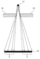
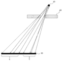
도 1은 종래의 엑스선 콜리메이터 및 이를 이용한 엑스선 영상 촬영 장치를 도시한 도면으로, 종래의 엑스선 영상 촬영 장치는, 엑스선 광원부(10), 엑스선 광원부(10)에서 방출된 엑스선의 조사영역을 조절하는 콜리메이터(20) 및 엑스선 광원부(10)에서 방출된 엑스선을 검출하는 디텍터(30)를 포함한다.FIG. 1 is a view showing a conventional X-ray collimator and an X-ray imaging apparatus using the same. FIG. 1 shows a conventional X-ray imaging apparatus including an
그러나, 도 1에 도시된 바와 같은 종래의 엑스선 콜리메이터 및 이를 이용한 엑스선 영상 촬영 장치는, 콜리메이터의 개구의 에지(edge)가 수직의 각진 형태를 나타내는바, 엑스선 광원부(10)로부터 방사선으로 조사되는 엑스선의 일부가 각진 에지 부분에서 간섭 내지는 일부 차단되어 디텍터(30)에서 획득한 영상의 가장자리 부분으로 반음영 부분(A)이 넓게 발생한다.However, the conventional X-ray collimator as shown in FIG. 1 and the X-ray imaging apparatus using the X-ray collimator as shown in FIG. 1 have angled vertical edges of the openings of the collimator, Part of the image is interrupted or partially blocked at the angled edge portion, so that the half-shaded portion A is widely formed as the edge portion of the image obtained by the
따라서, 엑스선 영상의 품질이 저하되기 쉽고, 만약 엑스선 영상으로부터 반음영 부분(A)을 제거할 경우에는 디텍터(30)의 면적을 충분히 활용할 수 없는 문제점이 있다.Therefore, the quality of the X-ray image tends to deteriorate, and if the half-shadowed portion A is removed from the X-ray image, the area of the
[선행기술문헌] 대한민국 등록특허공보 제10-1534098호[Prior art literature] Korean Patent Publication No. 10-1534098
본 발명은 상기와 같은 제반 문제점을 해결하기 위하여, 엑스선의 조사영역을 조절하는 콜리메이터 개구의 에지 부분을 종래의 각진 형태에서 만곡 형태로 변경함으로써, 엑스선의 불필요한 간섭이나 일부 차단에 따른 영향, 즉, 엑스선 영상 내 반음영 영역을 감소시키고, 이를 통하여 엑스선 영상의 품질을 높이며 엑스선 영상 촬영 장치를 보다 더 정확하게 제어할 수 있는 엑스선 콜리메이터 및 이를 이용한 엑스선 영상 촬영 장치를 제공하는데 그 목적이 있다.In order to solve the above problems, it is an object of the present invention to provide a collimator having an edge portion of a collimator opening that adjusts an irradiation area of an X-ray is changed from a conventional angled shape to a curved shape, It is an object of the present invention to provide an X-ray collimator capable of reducing the semi-shaded area in an X-ray image, thereby improving the quality of the X-ray image and more accurately controlling the X-ray imaging apparatus and an X-ray imaging apparatus using the same.
본 발명에 따른 엑스선 영상 촬영 장치는, 엑스선을 방출하는 엑스선 광원부; 상기 엑스선을 검출하는 엑스선 검출부; 상기 엑스선 광원부와 상기 엑스선 검출부 사이에서 상기 엑스선의 조사영역을 결정하는 개구를 제공하는 콜리메이터를 포함하고, 상기 개구는, 상기 엑스선 광원부를 향하는 입구측의 제1 에지와 상기 엑스선 검출부를 향하는 출구측의 제2 에지 중 적어도 하나가 만곡 형태이다.An x-ray imaging apparatus according to the present invention includes: an x-ray source unit for emitting an x-ray; An X-ray detector for detecting the X-ray; And a collimator for providing an opening for determining an irradiation area of the X-ray between the X-ray light source part and the X-ray detecting part, the opening including a first edge on the entrance side toward the X-ray light source part and a second edge on the exit side At least one of the second edges is curved.
여기서, 상기 엑스선 광원부와 상기 콜리메이터는 상대적인 위치가 고정되고, 상기 제1 에지는 수직의 각진 형태, 상기 제2 에지는 상기 만곡 형태일 수 있다.Here, the relative positions of the X-ray source part and the collimator are fixed, the first edge may be a vertical angled shape, and the second edge may be a curved shape.
또한, 상기 엑스선 검출부와 상기 콜리메이터는 일방향으로 상대 이동하고, 상기 개구 중 상기 이동 방향을 향하는 일측의 에지는 상기 제1 에지가 수직의 각진 형태, 상기 제2 에지가 만곡형태이고, 상기 개구 중 상기 일측을 제외한 나머지 에지는 상기 제1 에지 및 제2 에지가 상기 만곡 형태일 수 있다.The X-ray detecting unit and the collimator are relatively moved in one direction, and one edge of the opening facing the moving direction is a vertically angled shape of the first edge and a curved shape of the second edge. The remaining edges except for one side may have the first edge and the second edge in the curved shape.
한편, 상기 엑스선 검출부와 상기 콜리메이터는 양방향으로 상대 이동하고, 상기 개구의 에지는 상기 제1 에지 및 제2 에지가 상기 만곡 형태일 수 있다.Meanwhile, the X-ray detecting portion and the collimator may be moved in both directions, and the edge of the opening may have a curved shape at the first edge and the second edge.
또한, 상기 만곡 형태는, 원호 형태일 수 있다.Further, the curved shape may be an arc shape.
한편, 상기 만곡 형태는, 상기 제1 에지 및 제2 에지를 각진 형태로 가정할 때, 상기 엑스선 검출부에서 검출된 상기 엑스선의 세기가 상기 개구를 통화한 엑스선의 세기의 40% 이상 60% 이하인 부분 중 한 점과 상기 엑스선 광원부를 연결하는 선을 접선으로 하는 원호의 형태일 수 있다.On the other hand, in the curved shape, when the intensity of the X-ray detected by the X-ray detecting unit is 40% or more and 60% or less of the intensity of the X- And an arc that tangentially connects a line connecting the x-ray source unit and the x-ray source unit.
또한, 상기 원호의 곡률 반경은 상기 콜리메이터 두께 이하이고 상기 콜리메이터 두께의 1/2 이상일 수 있다.Further, the radius of curvature of the arc may be equal to or less than the thickness of the collimator, and may be equal to or more than one-half of the thickness of the collimator.
한편, 본 발명에 따른 엑스선 콜리메이터는, 엑스선을 방출하는 엑스선 광원부와 상기 엑스선을 검출하는 엑스선 검출부 사이에서 상기 엑스선의 조사영역을 결정하는 개구를 제공하는 엑스선 콜리메이터로서, 상기 엑스선 광원부와 상기 콜리메이터는 상대적인 위치가 고정될 경우, 상기 개구는 상기 엑스선 광원부를 향하는 제1 에지가 각진 형태 상기 엑스선 검출부를 향하는 제2 에지가 만곡 형태이고, 상기 엑스선 광원부와 상기 콜리메이터가 일방향으로 상대 이동될 경우, 상기 개구 중 상기 이동 방향을 향하는 일측은 상기 제1 에지가 각진 형태, 상기 제2 에지가 만곡 형태이며, 상기 일측을 제외한 나머지는 상기 제1 에지 및 제2 에지가 상기 만곡 형태이고, 상기 엑스선 광원부와 상기 콜리메이터가 양방향으로 상대 이동될 경우, 상기 개구는 상기 제1 에지 및 제2 에지가 상기 만곡 형태이다.The X-ray collimator according to the present invention is an X-ray collimator for providing an opening for determining an irradiation region of the X-ray between an X-ray source portion emitting an X-ray and an X-ray detecting portion detecting the X-ray, When the position is fixed, the opening has an angled first edge toward the x-ray light source portion, a second edge toward the x-ray detecting portion is a curved shape, and when the x-ray source portion and the collimator are relatively moved in one direction, Wherein the first edge and the second edge are curved, the first edge and the second edge facing each other in the moving direction are angled, the second edge is curved, When the movable member is moved in both directions relative to each other, The first and second edges are of the curved shape.
또한, 상기 만곡 형태는, 원호 형태일 수 있다.Further, the curved shape may be an arc shape.
한편, 상기 만곡 형태는, 상기 제1 에지 및 제2 에지를 각진 형태로 가정할 때, 상기 엑스선 검출부에서 검출된 상기 엑스선의 세기가 상기 개구를 통화한 엑스선의 세기의 40% 이상 60% 이하인 부분 중 한 점과 상기 엑스선 광원부를 연결하는 선을 접선으로 하는 원호의 형태일 수 있다.On the other hand, in the curved shape, when the intensity of the X-ray detected by the X-ray detecting unit is 40% or more and 60% or less of the intensity of the X- And an arc that tangentially connects a line connecting the x-ray source unit and the x-ray source unit.
본 발명에 따르면, 엑스선의 조사영역을 조절하는 콜리메이터의 개구의 에지 부분을 종래의 각진 형태에서 만곡 형태로 변경함으로써, 엑스선의 불필요한 간섭 내지는 일부 차단에 따른 영향, 즉, 엑스선 영상 내 반음영 부분을 감소시키고, 이를 통하여 엑스선 영상의 품질을 높이며 엑스선 영상 촬영 장치를 보다 더 정확하게 제어할 수 있는 효과가 있다.According to the present invention, by changing the edge portion of the opening of the collimator that adjusts the irradiation area of the X-rays from the conventional angular shape to the curved shape, the effect of unnecessary interference or partial blocking of the X-ray, Thereby improving the quality of the x-ray image and controlling the x-ray imaging apparatus more accurately.
도 1은 종래의 엑스선 콜리메이터 및 이를 이용한 엑스선 영상 촬영 장치를 도시한 도면이다.
도 2는 본 발명의 일 실시예에 따른 엑스선 콜리메이터 및 이를 이용한 엑스선 영상 촬영 장치를 도시한 도면이다.
도 3a 및 도 3b는 본 발명의 일 실시예에 따른 엑스선 콜리메이터의 다양한 구조를 도시한 도면이다.
도 4a 및 도 4b는 본 발명의 다른 실시예에 따른 엑스선 콜리메이터 및 이를 이용한 엑스선 영상 촬영 장치를 도시한 도면이다.
도 5는 종래의 스캔 모드를 제공하는 엑스선 콜리메이터 및 이를 이용한 엑스선 영상 촬영 장치를 도시한 도면이다.
도 6은 본 발명의 일 실시예에 따른 엑스선 콜리메이터 및 이를 이용한 엑스선 영상 촬영 장치의 콜리메이터 에지의 형성 방식을 나타낸 도면이다.
[부호의 설명]
100: 엑스선 광원부
200: 콜리메이터
300: 엑스선 검출부
400: 구동부1 is a view showing a conventional X-ray collimator and an X-ray imaging apparatus using the same.
2 is a view showing an X-ray collimator according to an embodiment of the present invention and an X-ray imaging apparatus using the same.
3A and 3B are views showing various structures of an X-ray collimator according to an embodiment of the present invention.
4A and 4B are views showing an X-ray collimator according to another embodiment of the present invention and an X-ray imaging apparatus using the same.
FIG. 5 is a view showing an X-ray collimator for providing a conventional scan mode and an X-ray imaging apparatus using the same.
FIG. 6 is a view illustrating a method of forming an X-ray collimator according to an embodiment of the present invention and a collimator edge of an X-ray imaging apparatus using the same.
[Description of Symbols]
100: X-ray light source part
200: collimator
300: X-ray detector
400:
이하에서는 도면을 참조하여 본 발명의 다양한 실시예를 설명한다. 실시예를 통해 본 발명의 기술적 사상이 좀 더 명확하게 이해될 수 있을 것이다. 또한, 본 발명이 이하에 설명된 실시예에 한정되는 것이 아니라 본 발명이 속하는 기술적 사상의 범위 내에서 다양한 형태로 변형될 수 있는 것이라는 점은 본 발명의 기술 분야에서 통상의 지식을 가진 자에게 명백할 것이다. 한편 동일한 도면 부호는 동일한 특성을 갖는 구성요소임을 나타내는 것으로서, 어느 도면에서 설명된 구성요소와 동일한 도면 부호를 갖는 구성요소에 대한 설명은 다른 도면에 대한 설명에서는 생략될 수 있다.Hereinafter, various embodiments of the present invention will be described with reference to the drawings. The technical idea of the present invention can be understood more clearly by way of examples. It will be apparent to those skilled in the art that various modifications and variations can be made in the present invention without departing from the spirit or scope of the invention. something to do. The same reference numerals denote elements having the same characteristics, and description of elements having the same reference numerals as those described in the drawings may be omitted in the description of other drawings.
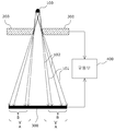
도 2는 본 발명의 일 실시예에 따른 엑스선 콜리메이터 및 이를 이용한 엑스선 영상 촬영 장치를 도시한 도면이고, 도 3a 및 도 3b는 본 발명의 일 실시예에 따른 엑스선 콜리메이터의 다양한 구조를 도시한 도면으로, 본 발명의 일 실시예에 따른 엑스선 영상 촬영 장치는, 엑스선 광원부(100), 콜리메이터(200), 엑스선 검출부(300) 및 구동부(400)를 포함할 수 있다.FIG. 2 is a view showing an X-ray collimator according to an embodiment of the present invention and an X-ray imaging apparatus using the same. FIGS. 3a and 3b are views showing various structures of an X-ray collimator according to an embodiment of the present invention An X-ray imaging apparatus according to an exemplary embodiment of the present invention may include an
엑스선 광원부(100)는 엑스선 검출부(300) 방향으로 방사상의 엑스선을 방출한다. 여기서, 엑스선 광원부(100)와 엑스선 검출부(300) 사이에는 피사체가 배치된다.The
콜리메이터(200)는 엑스선 광원부(100)으로부터 방출된 엑스선의 조사영역을 조절한다. 이를 위해 콜리메이터(200)는 엑스선 광원부(100)와 엑스선 검출부(300) 사이에서 엑스선의 조사영역을 결정하는 개구를 제공하고, 구동부(400)는 개구의 사이즈 및 형태를 조절한다. 이때, 콜리메이터(200)는 적어도 하나의 엑스선 차폐용 금속판을 포함할 수 있고, 구동부(400)는 적어도 하나의 차폐용 금속판을 이동시킴으로써 개구의 사이즈 및 형태를 조정할 수 있다.The
여기서, 콜리메이터(200)의 차폐용 금속판은 엑스선을 차단하는 금속재질로서 적어도 하나가 엑스선의 조사경로에 배치되어 엑스선이 통과하는 개구를 제공하되, 특히 개구의 에지 부분의 적어도 일부는 길이방향에 수직한 단면이 만곡 구조를 가진다. 즉, 콜리메이터(200)의 개구의 에지 부분의 적어도 일부의 길이방향에 수직한 단면을 종래의 각진 형태에서 만곡 형태로 변경함으로써, 엑스선의 간섭이나 일부 차단에 따른 영향, 즉, 엑스선 영상 내 반음영 영역을 감소시킬 수 있다. 이때, 만곡 구조는 일례로 소정 곡률을 갖는 원호 형태일 수 있다.Here, the shielding metal plate of the
여기서, 엑스선 영상 촬영 장치가 치과용 파노마라 영상, 단층 촬영 영상, 두부 촬영 영상 중 적어도 하나를 위한 것이고, 콜리메이터(200)의 차폐용 금속판의 재질이 납(Pb)인 것을 전제로 하면, 콜리메이터(200)의 차폐용 금속판의 두께는 적어도 2mm 내지 3mm는 되어야 엑스선의 차폐 효과를 볼 수 있다.Assuming that the X-ray imaging apparatus is for at least one of a dental panoramic image, a tomographic image, and a head-on imaging image, and the material of the shielding metal plate of the
또한, 콜리메이터(200)가 엑스선 광원부(100)에 대하여 상대적으로 고정된 위치에 배치되는 경우에, 콜리메이터(200)의 개구의 에지 중 엑스선 광원부(100)에 향하는 부분은 엑스선 영상의 반음영 영역에 큰 영향을 미치지 않으므로 도 2에 도시된 바와 같이 각진 형태를 유지할 수 있고, 콜리메이터(200)의 개구의 에지 중 엑스선 검출부(300)를 향하는 부분은 소정의 곡률을 갖는 만곡 구조일 수 있다. 즉, 콜리메이터(200)의 개구의 에지 중 엑스선 광원부(100)를 향하는 제1 에지는 각진 형태를 유지하고, 콜리메이터(200)의 개구의 에지 중 엑스선 검출부(300)에 향하는 제2 에지는 소정의 곡률을 갖는 곡면 형태를 가지는 만곡 구조일 수 있다.In the case where the
상술하면, 엑스선 광원부(100)에서 조사되는 엑스선은 방사상의 진행 경로를 나타낸다. 따라서 콜리메이터(200)가 엑스선 광원부(100)에 대하여 상대적으로 그 위치가 고정되는 경우에 콜리메이터(200)의 개구의 에지 중 엑스선 광원부(100)를 향하는 제1 에지로 조사된 엑스선은 콜리메이터에 의해 차단될 가능성이 상대적으로 높다. 반면 콜리메이터(200)의 개구의 에지 중 엑스선 검출부(300)를 향하는 제2 에지로 조사된 엑스선은 미처 차단되지 못하고 그 일부가 투과하거나 간섭을 일으킬 가능성이 높다. In detail, the x-rays irradiated from the
따라서, 콜리메이터(200)가 엑스선 광원부(100)에 대하여 상대적으로 그 위치가 고정되는 것을 전제로, 본 발명에 따른 콜리메이터(200)는 개구의 에지 중 엑스선 검출부(300)를 향하는 제2에지에 소정의 만곡 구조를 적용한다.Therefore, the
한편, 개구의 에지 부분이 만곡 구조를 갖는 본 발명에 따른 콜리메이터(200)는 다양한 방식의 콜리메이터에 적용 가능하다.On the other hand, the
예를 들면, 도 3a에 도시된 바와 같이 본 발명에 따른 콜리메이터는 적어도 하나의 차폐용 금속판을 포함하고, 적어도 하나의 차폐용 금속판 내부에 서로 다른 사이즈 및 형태를 갖는 통공(201, 202)이 관통되어 각각 개구를 형성할 수 있다. 이 경우 적어도 하나의 차폐용 금속판을 도 2에 도시된 구동부(400)를 통해 적절히 이동시킴으로써 원하는 사이즈 및 형태를 갖는 통공의 개구가 엑스선 광원부에 대응 배치되도록 할 수 있는데, 이 같은 형태, 이른바 윈도우 형태의 콜리메이터에 본 발명을 적용시켜 개구의 에지 부분을 만곡 구조로 할 수 있다.For example, as shown in FIG. 3A, the collimator according to the present invention includes at least one shielding metal plate, and the through
즉, 본 발명에 따른 콜리메이터(200)는 적어도 하나의 차폐용 금속판이 구동부(400)의 제어에 따라 이동하면서 서로 다른 사이즈 및 형태를 갖는 통공(201, 202) 중 어느 하나를 개구로 제공할 수 있고, 이러한 콜리메이터(200)의 통공, 즉 개구의 에지 부분에 만곡 구조를 적용하여 엑스선 영상 내 반음영 부분을 감소시킬 수 있다.That is, in the
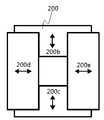
한편, 도 3b에 도시된 바와 같이 본 발명에 따른 콜리메이터는 서로 나란한 차폐용 금속판인 블레이드를 두 쌍으로 구비하고, 이들 두 쌍의 블레이드를 서로 교차 배치한 상태에서 구동부의 제어에 따라 적어도 한 쌍의 블레이드 사이 간격을 조절함으로써 그 사이로 형성되는 개구의 사이즈 및 형태를 조절할 수 있다. 이 같은 형태, 이른바 블래이드 형태의 콜리메이터에도 본 발명을 적용시켜 개구의 에지 부분을 만곡구조로 할 수 있다.As shown in FIG. 3B, the collimator according to the present invention includes two pairs of blades, ie, metal plates for shielding, which are parallel to each other. In a state where the two pairs of blades are crossed with each other, By adjusting the distance between the blades, the size and shape of the opening formed therebetween can be adjusted. The edge portion of the opening can be formed into a curved structure by applying the present invention to this type of collimator of the so-called blade type.
즉, 본 발명에 따른 콜리메이터는 4개의 블레이드가 구동부(400)의 제어에 따라 이동하면서 개구의 사이즈 및 형태를 조절할 수 있고, 이러한 콜리메이터의 개구의 에지 부분에 만곡 구조를 적용하여 엑스선 영상 내 반음영 부분을 감소시킬 수 있다.In other words, the collimator according to the present invention can adjust the size and shape of the opening while moving the four blades under the control of the
한편, 엑스선 검출부(300)는 콜리메이터(200)의 개구를 통해 조사되어 피사체를 투과한 엑스선을 감지하고, 감지된 결과를 영상 데이터 처리부(도시되지 않음)로 전달한다. 즉, 엑스선 검출부(300)는 미리 설정된 프레임 레이트로 피사체를 투과한 프레임 데이터를 획득하고, 영상 데이터 처리부는 엑스선 검출부(300)로부터 전달받은 프레임 데이터를 기초로 엑스선 영상을 획득하게 된다.The
이때, 엑스선 광원부(100)에서 방사상으로 조사되는 엑스선의 일부는 콜리메이터(200)의 개구의 에지 부분을 투과하게 되는데, 이로 인해 엑스선 검출부(300)에는 콜리메이터(200)에 의해 완전히 차단되지 않은 엑스선, 즉 개구의 에지 부분을 최대 길이로 투과하여 엑스선 검출부(300)에 도달하는 엑스선 경로(101)와 개구의 에지 부분을 최소 길이로 투과하여 엑스선 검출부(300)에 도달하는 엑스선 경로(102) 사이 영역에서 최초의 엑스선 대비 상대적으로 약한 세기의 엑스선이 검출된다. At this time, a part of the X-rays radiated from the
그리고 이 같은 엑스선의 영향으로 엑스선 영상에서 반음영 영역(B)이 나타나는바, 본 발명에 따른 엑스선 콜리메이터 및 이를 이용한 엑스선 영상 촬영 장치는 콜리메이터(200)의 개구의 에지 부분을 만곡 형태로 구현하여 종래의 엑스선 콜리메이터 및 이를 이용한 엑스선 영상 촬영 장치의 엑스선 영상 대비 반음영 영역(B)의 면적을 감소시킨다.The X-ray collimator according to the present invention and the X-ray imaging apparatus using the X-ray collimator according to the present invention can be realized by the curved shape of the edge portion of the opening of the
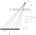
도 4a 및 도 4b는 본 발명의 다른 실시예에 따른 엑스선 콜리메이터 및 이를 이용한 엑스선 영상 촬영 장치를 도시한 도면으로, 구동부(400)는 콜리메이터(200)의 개구의 형태 및 사이즈를 조절하는 것 이외에도 엑스선 광원부(100)와 콜리메이터(200)의 상대적인 위치를 조정할 수 있다. 4A and 4B illustrate an X-ray collimator and an X-ray imaging apparatus using the X-ray collimator according to another embodiment of the present invention. In addition to adjusting the shape and size of the opening of the
이때, 엑스선 광원부(100)는 콜리메이터(200)의 개구를 통해 엑스선 검출부(300) 방향으로 엑스선을 조사하는데, 콜리메이터(200)가 엑스선 광원부(100)에 대해 상대적으로 위치 이동하면 콜리메이터(200)의 개구를 투과한 엑스선도 해당 방향을 따라 엑스선 검출부(300)에 스캔 조사된다. 즉, 콜리메이터(200)는 구동부(400)의 제어에 의하여 엑스선 광원부(100)에 대해 상대적으로 위치 이동될 수 있고, 이를 통하여 엑스선 조사 경로의 방향을 조절하여 엑스선 검출부(300)에 엑스선을 스캔 조사하는 스캔 모드를 진행할 수 있다.When the
이와 같이 콜리메이터(200)가 엑스선 광원부(100)에 대하여 상대적인 위치가 변화되는 경우에는 콜리메이터(200)의 개구의 에지 중 엑스선 광원부(100)에 향하는 제1 에지도 엑스선 영상의 반음영 영역에 영향을 미치는바, 도 4a 및 도 4b에 도시된 바와 같이 콜리메이터(200)의 개구의 에지 중 엑스선 광원부(100)에 향하는 제1 에지 및 콜리메이터(200)의 개구의 에지 중 엑스선 검출부(300)에 향하는 제2 에지 모두가 소정의 곡률을 갖는 만곡 구조를 나타낼 수 있고, 결국 개구의 에지는 반원 또는 이와 유사한 형태를 나타낼 수 있다.When the position of the
이때, 콜리메이터(200)가 엑스선 광원부(100)의 엑스선 조사 중에 일 방향으로만 이동하는 경우에는, 이동 방향을 향하는 개구의 일측의 에지는 도 2에 도시된 바와 같이 엑스선 검출부(300) 측에 대응하는 제2 에지가 만곡 형태를 갖고, 타측의 개구의 에지는 제1,2 에지가 모두 만곡인 반원 또는 이와 유사한 형태일 수 있다. At this time, when the
예를 들면, 도 4a에 도시된 바와 같이 엑스선 광원부(100)의 엑스선 조사 중에 콜리메이터(200)가 엑스선 광원부(100)에 대하여 일방향(200f)으로만 상대로 이동하는 경우, 콜리메이터(200)의 개구 중 이동방향을 향하는 일측의 에지는 엑스선 검출부(200) 방향의 제2 에지만 만곡 형태를 가지고, 타측의 에지는 제1 에지 및 제2 에지 모두 만곡인 반원 형태, 즉, 원호 형태를 나타낼 수 있다.For example, as shown in FIG. 4A, when the
반면에, 콜리메이터(200)가 엑스선 광원부(100)에 대하여 도 4a에 도시된 바과 같은 방향(200f) 및 도 4b에 도시된 바와 같은 방향(200g)으로 양방향 이동할 수 있는 경우에는, 콜리메이터(200)의 개구의 양 방향 에지 부분은 모두 제1,2 에지가 만곡인 반원 형태를 가질 수 있다.On the other hand, when the
한편, 이상에서는 엑스선 검출부(300)의 면적이 상대적으로 커서 엑스선 광원부(100)와 콜리메이터(200)의 상대적인 위치이동에 따라 엑스선 검출부(300)의 일부영역에 엑스선이 스캔 조사되는 것으로 설명하였지만, 필요하다면 엑스선 검출부(300)는 콜리메이터(200)를 투과한 엑스선에 대응되는 소면적을 나타내는 동시에 구동부(400)의 제어에 의해 엑스선 광원부(100)와 콜리메이터(200)의 상대적인 위치이동을 따른 엑스선의 스캔 조사방향을 따라 이동하면서 엑스선을 감지하는 것도 가능하다. In the above description, the area of the
이때, 구동부(400)는 엑스선 광원부(100), 콜리메이터(200), 엑스선 검출부(300)를 모두 이동시키는 것도 가능한데, 이 경우 구동부(400)는 엑스선 검출부(300)에 콜리메이터(200)의 개구를 투과한 엑스선이 검출될 수 있도록 엑스선 광원부(100), 콜리메이터(200), 엑스선 검출부(300)를 상호 동기화하여 이동시키게 된다. 예를 들면, 엑스선 광원부(100)와 콜리메이터(200)의 거리가 상대적으로 가까운 경우에는 콜리메이터(200)의 개구가 약간만 이동되어도 엑스선의 조사 경로가 개구의 이동방향을 따라 상대적으로 크게 이동되므로 그에 부합하도록 엑스선 검출부(300)를 이동시킨다. 반면에 엑스선 광원부(100)와 콜리메이터(200)의 거리가 상대적으로 먼 경우에는 콜리메이터(200)의 개구가 많이 이동되어도 엑스선의 조사 경로가 개구의 이동방향을 따라 상대적으로 작게 이동되므로 그에 부합하도록 엑스선 검출부(300)를 이동시킨다.In this case, the driving
도 4a 및 도 4b에 도시된 바와 같이 본 발명에 따른 엑스선 콜리메이터 및 이를 이용한 엑스선 영상 촬영 장치의 경우 반음영 영역(D)은 도 5에 도시된 바와 같은 종래의 각진 개구의 콜리메이터(20)에 비해 감소함을 알 수 있다.As shown in FIGS. 4A and 4B, the X-ray collimator according to the present invention and the X-ray imaging apparatus using the X-ray collimator according to the present invention are different from the conventional
도 6은 본 발명의 일 실시예에 따른 엑스선 콜리메이터 및 이를 이용한 엑스선 영상 촬영 장치의 콜리메이터(200)의 개구의 에지 부분을 형성하는 방식을 나타낸 도면이다.6 is a view illustrating a method of forming an edge portion of an opening of an X-ray collimator according to an embodiment of the present invention and a
편의상 콜리메이터(200)의 개구가 각진 것으로 가정할 때, 엑스선 영상의 반음영 영역은 엑스선 광원부(100)로부터 방사상으로 조사되는 엑스선 중 각진 형태의 에지를 최소 길이로 투과하는 제1 엑스선 경로(103)와 완전히 차단되는 엑스선 중 제1 엑스선 경로(103)와 최소 각도를 이루는 제2 엑스선 경로(101) 사이에서 나타난다. The semi-shaded area of the x-ray image is a
본 발명에 따른 콜리메이터의 개구는 이 같은 반음영 영역(A) 중 방사선 검출부(300)를 통해 검출된 엑스선의 세기(104)가 최초 엑스선 세기의 약 40% 내지 60% 검출되는 영역 중의 한 점, 바람직하게는 50%인 점(301)에 도달하는 제 3 엑스선 경로(102)를 접선으로 하는 어느 하나의 접점(102a)을 기준으로 소정의 곡률(Curvature)을 갖도록 만곡될 수 있다.The opening of the collimator according to the present invention is one of the areas where the
이때, 곡률 반경 및 접점(102a)은 임의로 결정될 수 있으나, 곡률 반경은 콜리메이터, 엄밀하게는 차폐형 금속판의 두께 이하이고, 차폐형 금속판 두께의 1/2 이상인 것이 바람직하다. 또한, 콜리메이터의 개구의 에지는 연속적으로 다수의 곡률로 만곡되는 것도 가능하며, 이 경우 접선에 대응하는 곡률이 그 주변에 대응하는 곡률보다 크게 형성되는 것이 바람직하다.At this time, the radius of curvature and the
상술한 바와 같은 본 발명의 일 실시예에 따른 엑스선 콜리메이터 및 이를 이용한 엑스선 영상 촬영 장치에 의하면, 36mm 폭의 엑스선 검출부(300)에 대하여 약 3mm 폭의 반음영 영역을 감소시킬 수 있다.According to the X-ray collimator and the X-ray imaging apparatus using the X-ray collimator according to an embodiment of the present invention, the half-shaded area of about 3 mm in width can be reduced with respect to the X-
한편, 반음영 영역이 감소함에 따라, 영상의 품질을 높이는 것은 물론 구동부(400)에 의한 제어의 정확성도 증가하는 효과가 있다. 따라서 본 발명은 엑스선 조사범위의 고속제어가 필요한 엑스선 영상, 특히 스캔 방식의 세팔로 영상에 적용될 경우에 그 효과가 클 수 있다. On the other hand, as the semi-shaded area decreases, the quality of the image is enhanced, and the accuracy of the control by the driving
이상에서 설명한 본 발명은 전술한 실시예 및 도면에 한정되는 것이 아니고, 본 발명의 기술적 사상을 벗어나지 않는 범위 내에서 얼마든지, 치환, 변경 및 변형이 가능하다는 것은 본 발명이 속하는 분야에서 통상의 지식을 가진 자에게 있어서 명백할 것이다.While the present invention has been described in connection with what is presently considered to be practical exemplary embodiments, it is to be understood that the invention is not limited to the disclosed embodiments, but, on the contrary, It will be clear to those who have.
Claims (10)
상기 엑스선을 검출하는 엑스선 검출부;
상기 엑스선 광원부와 상기 엑스선 검출부 사이에서 상기 엑스선의 조사영역을 결정하는 개구를 제공하는 콜리메이터를 포함하고,
상기 개구는, 상기 엑스선 광원부를 향하는 입구측의 제1 에지와 상기 엑스선 검출부를 향하는 출구측의 제2 에지 중 적어도 하나가 만곡 형태인 엑스선 영상 촬영 장치.An x-ray source portion for emitting x-rays;
An X-ray detector for detecting the X-ray;
And a collimator provided between the x-ray source part and the x-ray detector part to provide an opening for determining an irradiation area of the x-
Wherein the opening has at least one of a first edge on the entrance side facing the x-ray source part and a second edge on the exit side facing the x-ray detection part is curved.
상기 엑스선 광원부와 상기 콜리메이터는 상대적인 위치가 고정되고,
상기 제1 에지는 수직의 각진 형태, 상기 제2 에지는 상기 만곡 형태인 엑스선 영상 촬영 장치.The method according to claim 1,
The relative position of the X-ray source part and the collimator is fixed,
Wherein the first edge is a vertically angled shape and the second edge is a curved shape.
상기 엑스선 검출부와 상기 콜리메이터는 일방향으로 상대 이동하고,
상기 개구 중 상기 이동 방향을 향하는 일측의 에지는 상기 제1 에지가 수직의 각진 형태, 상기 제2 에지가 만곡형태이고,
상기 개구 중 상기 일측을 제외한 나머지 에지는 상기 제1 에지 및 제2 에지가 상기 만곡 형태인 엑스선 영상 촬영 장치.The method according to claim 1,
The X-ray detector and the collimator are relatively moved in one direction,
Wherein one edge of the opening facing the moving direction is formed so that the first edge is a vertically angled shape and the second edge is a curved shape,
Wherein the first edge and the second edge of the opening other than the one side are curved shapes.
상기 엑스선 검출부와 상기 콜리메이터는 양방향으로 상대 이동하고,
상기 개구의 에지는 상기 제1 에지 및 제2 에지가 상기 만곡 형태인 엑스선 영상 촬영 장치.The method according to claim 1,
Wherein the X-ray detecting unit and the collimator are relatively moved in both directions,
Wherein the edge of the opening is the curved shape of the first edge and the second edge.
상기 만곡 형태는, 원호 형태인 엑스선 영상 촬영 장치.The method according to any one of claims 1 to 4,
Wherein the curved shape is an arcuate shape.
상기 만곡 형태는,
상기 제1 에지 및 제2 에지를 각진 형태로 가정할 때, 상기 엑스선 검출부에서 검출된 상기 엑스선의 세기가 상기 개구를 통화한 엑스선의 세기의 40% 이상 60% 이하인 부분 중 한 점과 상기 엑스선 광원부를 연결하는 선을 접선으로 하는 원호의 형태인 엑스선 영상 촬영장치.The method according to claim 1,
Preferably,
Ray detecting unit detects that the intensity of the X-ray detected by the X-ray detecting unit is 40% or more and 60% or less of the intensity of the X-ray with which the opening is communicated, Ray image taking device in the form of a circular arc which tangentially connects a line connecting the X-
상기 원호의 곡률 반경은 상기 콜리메이터 두께 이하이고 상기 콜리메이터 두께의 1/2 이상인 엑스선 영상 촬영 장치.The method of claim 6,
Wherein the radius of curvature of the arc is less than or equal to the thickness of the collimator and equal to or greater than a half of the thickness of the collimator.
상기 엑스선 광원부와 상기 콜리메이터는 상대적인 위치가 고정될 경우,
상기 개구는 상기 엑스선 광원부를 향하는 제1 에지가 각진 형태 상기 엑스선 검출부를 향하는 제2 에지가 만곡 형태이고,
상기 엑스선 광원부와 상기 콜리메이터가 일방향으로 상대 이동될 경우,
상기 개구 중 상기 이동 방향을 향하는 일측은 상기 제1 에지가 각진 형태, 상기 제2 에지가 만곡 형태이며, 상기 일측을 제외한 나머지는 상기 제1 에지 및 제2 에지가 상기 만곡 형태이고,
상기 엑스선 광원부와 상기 콜리메이터가 양방향으로 상대 이동될 경우,
상기 개구는 상기 제1 에지 및 제2 에지가 상기 만곡 형태인 엑스선 콜리메이터.An X-ray collimator for providing an opening for determining an irradiation region of the X-ray between an X-ray source portion emitting an X-ray and an X-ray detecting portion detecting the X-
When the relative position of the X-ray source part and the collimator is fixed,
Wherein the opening has an angled first edge toward the x-ray light source portion and a second edge directed toward the x-
When the X-ray source part and the collimator are relatively moved in one direction,
Wherein one side of the opening facing the moving direction has the first edge in an angled shape and the second edge in a curved shape and the remaining one except the one side has the curved shape of the first edge and the second edge,
When the X-ray source part and the collimator are relatively moved in both directions,
Wherein the aperture is the curved shape of the first edge and the second edge.
상기 만곡 형태는, 원호 형태인 엑스선 콜리메이터.The method of claim 8,
The curved shape is an arc-shaped X-ray collimator.
상기 만곡 형태는,
상기 제1 에지 및 제2 에지를 각진 형태로 가정할 때, 상기 엑스선 검출부에서 검출된 상기 엑스선의 세기가 상기 개구를 통화한 엑스선의 세기의 40% 이상 60% 이하인 부분 중 한 점과 상기 엑스선 광원부를 연결하는 선을 접선으로 하는 원호의 형태인 엑스선 콜리메이터.The method of claim 8,
Preferably,
Ray detecting unit detects that the intensity of the X-ray detected by the X-ray detecting unit is 40% or more and 60% or less of the intensity of the X-ray with which the opening is communicated, X-ray collimator in the form of an arc that tangentially connects the line connecting the X-
Applications Claiming Priority (3)
| Application Number | Priority Date | Filing Date | Title |
|---|---|---|---|
| KR1020160014976A KR20170093500A (en) | 2016-02-05 | 2016-02-05 | X-ray collimator and x-ray imaging apparatus using the same |
| KR1020160014976 | 2016-02-05 | ||
| PCT/KR2017/001274 WO2017135782A1 (en) | 2016-02-05 | 2017-02-06 | X-ray collimator and x-ray imaging apparatus using same |
Publications (2)
| Publication Number | Publication Date |
|---|---|
| KR20180098411A true KR20180098411A (en) | 2018-09-03 |
| KR102163767B1 KR102163767B1 (en) | 2020-10-08 |
Family
ID=59500407
Family Applications (2)
| Application Number | Title | Priority Date | Filing Date |
|---|---|---|---|
| KR1020160014976A Pending KR20170093500A (en) | 2016-02-05 | 2016-02-05 | X-ray collimator and x-ray imaging apparatus using the same |
| KR1020187023342A Active KR102163767B1 (en) | 2016-02-05 | 2017-02-06 | X-ray collimator and X-ray imaging apparatus using the same |
Family Applications Before (1)
| Application Number | Title | Priority Date | Filing Date |
|---|---|---|---|
| KR1020160014976A Pending KR20170093500A (en) | 2016-02-05 | 2016-02-05 | X-ray collimator and x-ray imaging apparatus using the same |
Country Status (5)
| Country | Link |
|---|---|
| US (1) | US10638984B2 (en) |
| EP (1) | EP3412210B1 (en) |
| KR (2) | KR20170093500A (en) |
| CN (1) | CN108778138B (en) |
| WO (1) | WO2017135782A1 (en) |
Cited By (1)
| Publication number | Priority date | Publication date | Assignee | Title |
|---|---|---|---|---|
| KR20240072657A (en) * | 2022-11-17 | 2024-05-24 | 주식회사 우리엔 | X-Ray Imaging Apparatus |
Families Citing this family (23)
| Publication number | Priority date | Publication date | Assignee | Title |
|---|---|---|---|---|
| KR20170093500A (en) * | 2016-02-05 | 2017-08-16 | 주식회사바텍 | X-ray collimator and x-ray imaging apparatus using the same |
| EP3442421B1 (en) * | 2016-04-11 | 2020-11-25 | Dedicated2Imaging, LLC | C-arm with integrated ct system |
| CN110325098A (en) | 2016-11-28 | 2019-10-11 | 适内有限责任公司 | With the endoscope for separating disposable axis |
| US10586624B2 (en) * | 2017-07-31 | 2020-03-10 | H3D, Inc. | Control of imaging assembly with interchangeable radiation shielding |
| US10433798B2 (en) * | 2017-09-29 | 2019-10-08 | General Electric Company | Aperture, collimator, and X-ray tomographic imaging apparatus |
| DE102018112054B4 (en) * | 2018-05-18 | 2023-02-09 | Yxlon International Gmbh | X-ray tube with collimator and collimator device for closed X-ray tube |
| US10948428B2 (en) * | 2018-05-25 | 2021-03-16 | Delavan Inc. | Reducing scatter for computed tomography |
| USD1018844S1 (en) | 2020-01-09 | 2024-03-19 | Adaptivendo Llc | Endoscope handle |
| CN112107324B (en) * | 2020-09-03 | 2024-04-26 | 上海联影医疗科技股份有限公司 | Scanning method, medium and medical equipment for digital breast tomosynthesis equipment |
| USD1051380S1 (en) | 2020-11-17 | 2024-11-12 | Adaptivendo Llc | Endoscope handle |
| CN112727865A (en) * | 2021-01-01 | 2021-04-30 | 滨松光子医疗科技(廊坊)有限公司 | Mechanism suitable for collimator pinhole head installation is fixed |
| CN113063807A (en) * | 2021-03-12 | 2021-07-02 | 梅特勒-托利多(常州)测量技术有限公司 | Ray light field adjusting mechanism and ray imaging device |
| USD1031035S1 (en) | 2021-04-29 | 2024-06-11 | Adaptivendo Llc | Endoscope handle |
| USD1070082S1 (en) | 2021-04-29 | 2025-04-08 | Adaptivendo Llc | Endoscope handle |
| USD1066659S1 (en) | 2021-09-24 | 2025-03-11 | Adaptivendo Llc | Endoscope handle |
| KR102548631B1 (en) * | 2021-09-29 | 2023-06-27 | 국립암센터 | Irradiation apparatus and irradiation method using the same |
| CN114098787A (en) * | 2021-11-04 | 2022-03-01 | 明峰医疗系统股份有限公司 | Collimator with focus tracking function |
| CN114305478B (en) * | 2021-12-22 | 2024-12-20 | 明峰医疗系统股份有限公司 | A collimator, CT equipment, calibration method and preparation method |
| KR20240057560A (en) | 2022-10-25 | 2024-05-03 | 주식회사 리스템 | A blade-type collimator applied to a C-type X-ray imaging device |
| EP4390973A4 (en) * | 2022-11-04 | 2024-12-25 | Contemporary Amperex Technology (Hong Kong) Limited | COLLIMATOR, RADIOACTIVE SOURCE CONTAINER, DETECTOR, INSTRUMENT, APPARATUS AND SYSTEM FOR SURFACE DENSITY |
| CN219015981U (en) * | 2022-11-04 | 2023-05-12 | 宁德时代新能源科技股份有限公司 | Collimator, radioactive source box, detector, surface density meter, pole piece weight detection device and pole piece production system |
| KR102752687B1 (en) * | 2023-06-30 | 2025-01-10 | 오스템임플란트 주식회사 | X-ray imaging apparatus |
| KR20250122170A (en) | 2024-02-06 | 2025-08-13 | 오스템글로벌 주식회사 | Collimator for x-ray imaging apparatus |
Citations (4)
| Publication number | Priority date | Publication date | Assignee | Title |
|---|---|---|---|---|
| US4534052A (en) * | 1982-04-02 | 1985-08-06 | C.G.R. - Mev | Block for partially limiting a radiation beam, and a collimator comprising such blocks |
| US6320929B1 (en) * | 1999-02-12 | 2001-11-20 | Siemens Aktiengesellschaft | Method for scanning an examination subject with a CT device |
| US20080063147A1 (en) * | 2006-09-12 | 2008-03-13 | John Juschka | Multileaf collimator |
| US20140146948A1 (en) * | 2012-11-27 | 2014-05-29 | Ge Medical Systems Global Technology Company, Llc | Ct collimator and ct system including the ct collimator |
Family Cites Families (15)
| Publication number | Priority date | Publication date | Assignee | Title |
|---|---|---|---|---|
| GB2211710A (en) * | 1987-10-28 | 1989-07-05 | Philips Nv | Multileaf collimator |
| US5165106A (en) * | 1991-06-06 | 1992-11-17 | Siemens Medical Laboratories, Inc. | Contour collimator |
| US5166531A (en) * | 1991-08-05 | 1992-11-24 | Varian Associates, Inc. | Leaf-end configuration for multileaf collimator |
| JP2004357956A (en) | 2003-06-05 | 2004-12-24 | Ge Medical Systems Global Technology Co Llc | X-ray photographing device and collimator |
| US7076029B2 (en) * | 2003-10-27 | 2006-07-11 | General Electric Company | Method and apparatus of radiographic imaging with an energy beam tailored for a subject to be scanned |
| JP4891673B2 (en) | 2005-06-30 | 2012-03-07 | 株式会社東芝 | X-ray CT system |
| US7535987B2 (en) | 2005-06-30 | 2009-05-19 | Kabushiki Kaisha Toshiba | X-ray CT apparatus |
| US8637841B2 (en) * | 2010-08-23 | 2014-01-28 | Varian Medical Systems, Inc. | Multi level multileaf collimators |
| US8311184B2 (en) | 2010-08-30 | 2012-11-13 | General Electric Company | Fan-shaped X-ray beam imaging systems employing graded multilayer optic devices |
| KR101534098B1 (en) | 2013-09-13 | 2015-07-07 | 삼성전자주식회사 | Computed tomography apparatus and method for controlling x-ray by using the same |
| DE102013222209A1 (en) | 2013-10-31 | 2015-04-30 | Fraunhofer-Gesellschaft zur Förderung der angewandten Forschung e.V. | Blinding system for a radiation source and apparatus and method for taking a projection image and for determining a relative position between a radiation source and a radiation detector |
| JP2015092953A (en) * | 2013-11-11 | 2015-05-18 | キヤノン株式会社 | Radiographic apparatus and radiographic imaging system |
| CN104835547B (en) * | 2014-02-11 | 2019-11-19 | 上海联影医疗科技有限公司 | Multi-diaphragm collimator |
| CN104795122B (en) * | 2014-05-28 | 2017-11-28 | 上海联影医疗科技有限公司 | Selection method of collimator, radiation system and collimator blades |
| KR20170093500A (en) * | 2016-02-05 | 2017-08-16 | 주식회사바텍 | X-ray collimator and x-ray imaging apparatus using the same |
-
2016
- 2016-02-05 KR KR1020160014976A patent/KR20170093500A/en active Pending
-
2017
- 2017-02-06 KR KR1020187023342A patent/KR102163767B1/en active Active
- 2017-02-06 WO PCT/KR2017/001274 patent/WO2017135782A1/en not_active Ceased
- 2017-02-06 EP EP17747825.2A patent/EP3412210B1/en active Active
- 2017-02-06 US US16/075,751 patent/US10638984B2/en active Active
- 2017-02-06 CN CN201780015398.8A patent/CN108778138B/en active Active
Patent Citations (4)
| Publication number | Priority date | Publication date | Assignee | Title |
|---|---|---|---|---|
| US4534052A (en) * | 1982-04-02 | 1985-08-06 | C.G.R. - Mev | Block for partially limiting a radiation beam, and a collimator comprising such blocks |
| US6320929B1 (en) * | 1999-02-12 | 2001-11-20 | Siemens Aktiengesellschaft | Method for scanning an examination subject with a CT device |
| US20080063147A1 (en) * | 2006-09-12 | 2008-03-13 | John Juschka | Multileaf collimator |
| US20140146948A1 (en) * | 2012-11-27 | 2014-05-29 | Ge Medical Systems Global Technology Company, Llc | Ct collimator and ct system including the ct collimator |
Cited By (1)
| Publication number | Priority date | Publication date | Assignee | Title |
|---|---|---|---|---|
| KR20240072657A (en) * | 2022-11-17 | 2024-05-24 | 주식회사 우리엔 | X-Ray Imaging Apparatus |
Also Published As
| Publication number | Publication date |
|---|---|
| US20190029614A1 (en) | 2019-01-31 |
| CN108778138B (en) | 2021-12-21 |
| KR20170093500A (en) | 2017-08-16 |
| EP3412210A4 (en) | 2019-08-07 |
| KR102163767B1 (en) | 2020-10-08 |
| WO2017135782A1 (en) | 2017-08-10 |
| EP3412210B1 (en) | 2020-08-05 |
| CN108778138A (en) | 2018-11-09 |
| US10638984B2 (en) | 2020-05-05 |
| EP3412210A1 (en) | 2018-12-12 |
Similar Documents
| Publication | Publication Date | Title |
|---|---|---|
| KR20180098411A (en) | X-ray collimator and X-ray imaging apparatus using the same | |
| EP2718936B1 (en) | Multiple focal spot x-ray radiation filtering | |
| KR101076319B1 (en) | Cone beam CT device with collimator with dynamic control | |
| JP2010240106A (en) | X-ray imaging device, control method therefor and computer program | |
| US9239304B2 (en) | X-ray imaging apparatus | |
| US9655577B2 (en) | Apparatus and method for diagnosing lesions | |
| US10709405B2 (en) | X-ray CT scanning apparatus and scanning method thereof | |
| JPH05256950A (en) | Solid detector for x-ray computer tomography | |
| CN108903963B (en) | An X-ray shielding assembly and a front collimator thereof | |
| JP6307268B2 (en) | Collimator for use in CT system | |
| KR102279966B1 (en) | Dental x-ray imaging apparatus | |
| US8625738B2 (en) | Radiation therapy and scanning system | |
| CN109788928B (en) | Radiation phase difference imaging device | |
| KR102752687B1 (en) | X-ray imaging apparatus | |
| JP4436342B2 (en) | Radiotherapy apparatus control apparatus and radiation irradiation method | |
| KR102339064B1 (en) | Rotary x-ray collimator and x-ray imaging apparatus comprising the same | |
| JP6034687B2 (en) | X-ray imaging apparatus and light shielding apparatus for X-ray imaging | |
| KR101793100B1 (en) | X-ray examination apparatus | |
| JP4770594B2 (en) | Tomography equipment | |
| JP2004248983A (en) | Radiation detector | |
| US10276276B1 (en) | Radiation phase-contrast image capturing device | |
| JP6372614B2 (en) | Radiation source and radiation phase contrast imaging apparatus having the same | |
| CN121399500A (en) | Modular computed tomography detector configuration | |
| JPH11285489A (en) | Radiation exposure position adjusting method, radiation exposure and detection device and tomograph |
Legal Events
| Date | Code | Title | Description |
|---|---|---|---|
| A201 | Request for examination | ||
| PA0105 | International application |
Patent event date: 20180813 Patent event code: PA01051R01D Comment text: International Patent Application |
|
| PA0201 | Request for examination | ||
| PG1501 | Laying open of application | ||
| E902 | Notification of reason for refusal | ||
| PE0902 | Notice of grounds for rejection |
Comment text: Notification of reason for refusal Patent event date: 20200115 Patent event code: PE09021S01D |
|
| E701 | Decision to grant or registration of patent right | ||
| PE0701 | Decision of registration |
Patent event code: PE07011S01D Comment text: Decision to Grant Registration Patent event date: 20200710 |
|
| GRNT | Written decision to grant | ||
| PR0701 | Registration of establishment |
Comment text: Registration of Establishment Patent event date: 20200929 Patent event code: PR07011E01D |
|
| PR1002 | Payment of registration fee |
Payment date: 20201005 End annual number: 3 Start annual number: 1 |
|
| PG1601 | Publication of registration | ||
| PR1001 | Payment of annual fee |
Payment date: 20230703 Start annual number: 4 End annual number: 4 |
|
| PR1001 | Payment of annual fee |
Payment date: 20240703 Start annual number: 5 End annual number: 5 |
|
| PR1001 | Payment of annual fee |
Payment date: 20250701 Start annual number: 6 End annual number: 6 |