KR20180098376A - Construction material container - Google Patents
Construction material container Download PDFInfo
- Publication number
- KR20180098376A KR20180098376A KR1020187021646A KR20187021646A KR20180098376A KR 20180098376 A KR20180098376 A KR 20180098376A KR 1020187021646 A KR1020187021646 A KR 1020187021646A KR 20187021646 A KR20187021646 A KR 20187021646A KR 20180098376 A KR20180098376 A KR 20180098376A
- Authority
- KR
- South Korea
- Prior art keywords
- reservoir
- container
- build
- exit
- wall
- Prior art date
- Legal status (The legal status is an assumption and is not a legal conclusion. Google has not performed a legal analysis and makes no representation as to the accuracy of the status listed.)
- Granted
Links
Images


Classifications
-
- B—PERFORMING OPERATIONS; TRANSPORTING
- B29—WORKING OF PLASTICS; WORKING OF SUBSTANCES IN A PLASTIC STATE IN GENERAL
- B29C—SHAPING OR JOINING OF PLASTICS; SHAPING OF MATERIAL IN A PLASTIC STATE, NOT OTHERWISE PROVIDED FOR; AFTER-TREATMENT OF THE SHAPED PRODUCTS, e.g. REPAIRING
- B29C64/00—Additive manufacturing, i.e. manufacturing of three-dimensional [3D] objects by additive deposition, additive agglomeration or additive layering, e.g. by 3D printing, stereolithography or selective laser sintering
- B29C64/30—Auxiliary operations or equipment
- B29C64/307—Handling of material to be used in additive manufacturing
- B29C64/321—Feeding
- B29C64/329—Feeding using hoppers
-
- B—PERFORMING OPERATIONS; TRANSPORTING
- B29—WORKING OF PLASTICS; WORKING OF SUBSTANCES IN A PLASTIC STATE IN GENERAL
- B29C—SHAPING OR JOINING OF PLASTICS; SHAPING OF MATERIAL IN A PLASTIC STATE, NOT OTHERWISE PROVIDED FOR; AFTER-TREATMENT OF THE SHAPED PRODUCTS, e.g. REPAIRING
- B29C31/00—Handling, e.g. feeding of the material to be shaped, storage of plastics material before moulding; Automation, i.e. automated handling lines in plastics processing plants, e.g. using manipulators or robots
- B29C31/02—Dispensing from vessels, e.g. hoppers
-
- B—PERFORMING OPERATIONS; TRANSPORTING
- B22—CASTING; POWDER METALLURGY
- B22F—WORKING METALLIC POWDER; MANUFACTURE OF ARTICLES FROM METALLIC POWDER; MAKING METALLIC POWDER; APPARATUS OR DEVICES SPECIALLY ADAPTED FOR METALLIC POWDER
- B22F12/00—Apparatus or devices specially adapted for additive manufacturing; Auxiliary means for additive manufacturing; Combinations of additive manufacturing apparatus or devices with other processing apparatus or devices
- B22F12/50—Means for feeding of material, e.g. heads
- B22F12/52—Hoppers
-
- B22F3/1055—
-
- B—PERFORMING OPERATIONS; TRANSPORTING
- B29—WORKING OF PLASTICS; WORKING OF SUBSTANCES IN A PLASTIC STATE IN GENERAL
- B29C—SHAPING OR JOINING OF PLASTICS; SHAPING OF MATERIAL IN A PLASTIC STATE, NOT OTHERWISE PROVIDED FOR; AFTER-TREATMENT OF THE SHAPED PRODUCTS, e.g. REPAIRING
- B29C64/00—Additive manufacturing, i.e. manufacturing of three-dimensional [3D] objects by additive deposition, additive agglomeration or additive layering, e.g. by 3D printing, stereolithography or selective laser sintering
- B29C64/10—Processes of additive manufacturing
- B29C64/141—Processes of additive manufacturing using only solid materials
- B29C64/153—Processes of additive manufacturing using only solid materials using layers of powder being selectively joined, e.g. by selective laser sintering or melting
-
- B—PERFORMING OPERATIONS; TRANSPORTING
- B29—WORKING OF PLASTICS; WORKING OF SUBSTANCES IN A PLASTIC STATE IN GENERAL
- B29C—SHAPING OR JOINING OF PLASTICS; SHAPING OF MATERIAL IN A PLASTIC STATE, NOT OTHERWISE PROVIDED FOR; AFTER-TREATMENT OF THE SHAPED PRODUCTS, e.g. REPAIRING
- B29C64/00—Additive manufacturing, i.e. manufacturing of three-dimensional [3D] objects by additive deposition, additive agglomeration or additive layering, e.g. by 3D printing, stereolithography or selective laser sintering
- B29C64/10—Processes of additive manufacturing
- B29C64/165—Processes of additive manufacturing using a combination of solid and fluid materials, e.g. a powder selectively bound by a liquid binder, catalyst, inhibitor or energy absorber
-
- B—PERFORMING OPERATIONS; TRANSPORTING
- B29—WORKING OF PLASTICS; WORKING OF SUBSTANCES IN A PLASTIC STATE IN GENERAL
- B29C—SHAPING OR JOINING OF PLASTICS; SHAPING OF MATERIAL IN A PLASTIC STATE, NOT OTHERWISE PROVIDED FOR; AFTER-TREATMENT OF THE SHAPED PRODUCTS, e.g. REPAIRING
- B29C64/00—Additive manufacturing, i.e. manufacturing of three-dimensional [3D] objects by additive deposition, additive agglomeration or additive layering, e.g. by 3D printing, stereolithography or selective laser sintering
- B29C64/20—Apparatus for additive manufacturing; Details thereof or accessories therefor
- B29C64/255—Enclosures for the building material, e.g. powder containers
-
- B—PERFORMING OPERATIONS; TRANSPORTING
- B29—WORKING OF PLASTICS; WORKING OF SUBSTANCES IN A PLASTIC STATE IN GENERAL
- B29C—SHAPING OR JOINING OF PLASTICS; SHAPING OF MATERIAL IN A PLASTIC STATE, NOT OTHERWISE PROVIDED FOR; AFTER-TREATMENT OF THE SHAPED PRODUCTS, e.g. REPAIRING
- B29C64/00—Additive manufacturing, i.e. manufacturing of three-dimensional [3D] objects by additive deposition, additive agglomeration or additive layering, e.g. by 3D printing, stereolithography or selective laser sintering
- B29C64/30—Auxiliary operations or equipment
- B29C64/307—Handling of material to be used in additive manufacturing
-
- B—PERFORMING OPERATIONS; TRANSPORTING
- B29—WORKING OF PLASTICS; WORKING OF SUBSTANCES IN A PLASTIC STATE IN GENERAL
- B29C—SHAPING OR JOINING OF PLASTICS; SHAPING OF MATERIAL IN A PLASTIC STATE, NOT OTHERWISE PROVIDED FOR; AFTER-TREATMENT OF THE SHAPED PRODUCTS, e.g. REPAIRING
- B29C64/00—Additive manufacturing, i.e. manufacturing of three-dimensional [3D] objects by additive deposition, additive agglomeration or additive layering, e.g. by 3D printing, stereolithography or selective laser sintering
- B29C64/30—Auxiliary operations or equipment
- B29C64/357—Recycling
-
- B—PERFORMING OPERATIONS; TRANSPORTING
- B29—WORKING OF PLASTICS; WORKING OF SUBSTANCES IN A PLASTIC STATE IN GENERAL
- B29C—SHAPING OR JOINING OF PLASTICS; SHAPING OF MATERIAL IN A PLASTIC STATE, NOT OTHERWISE PROVIDED FOR; AFTER-TREATMENT OF THE SHAPED PRODUCTS, e.g. REPAIRING
- B29C67/00—Shaping techniques not covered by groups B29C39/00 - B29C65/00, B29C70/00 or B29C73/00
- B29C67/24—Shaping techniques not covered by groups B29C39/00 - B29C65/00, B29C70/00 or B29C73/00 characterised by the choice of material
-
- B—PERFORMING OPERATIONS; TRANSPORTING
- B32—LAYERED PRODUCTS
- B32B—LAYERED PRODUCTS, i.e. PRODUCTS BUILT-UP OF STRATA OF FLAT OR NON-FLAT, e.g. CELLULAR OR HONEYCOMB, FORM
- B32B27/00—Layered products comprising a layer of synthetic resin
- B32B27/30—Layered products comprising a layer of synthetic resin comprising vinyl (co)polymers; comprising acrylic (co)polymers
- B32B27/302—Layered products comprising a layer of synthetic resin comprising vinyl (co)polymers; comprising acrylic (co)polymers comprising aromatic vinyl (co)polymers, e.g. styrenic (co)polymers
-
- B—PERFORMING OPERATIONS; TRANSPORTING
- B32—LAYERED PRODUCTS
- B32B—LAYERED PRODUCTS, i.e. PRODUCTS BUILT-UP OF STRATA OF FLAT OR NON-FLAT, e.g. CELLULAR OR HONEYCOMB, FORM
- B32B27/00—Layered products comprising a layer of synthetic resin
- B32B27/30—Layered products comprising a layer of synthetic resin comprising vinyl (co)polymers; comprising acrylic (co)polymers
- B32B27/306—Layered products comprising a layer of synthetic resin comprising vinyl (co)polymers; comprising acrylic (co)polymers comprising vinyl acetate or vinyl alcohol (co)polymers
-
- B—PERFORMING OPERATIONS; TRANSPORTING
- B32—LAYERED PRODUCTS
- B32B—LAYERED PRODUCTS, i.e. PRODUCTS BUILT-UP OF STRATA OF FLAT OR NON-FLAT, e.g. CELLULAR OR HONEYCOMB, FORM
- B32B27/00—Layered products comprising a layer of synthetic resin
- B32B27/30—Layered products comprising a layer of synthetic resin comprising vinyl (co)polymers; comprising acrylic (co)polymers
- B32B27/308—Layered products comprising a layer of synthetic resin comprising vinyl (co)polymers; comprising acrylic (co)polymers comprising acrylic (co)polymers
-
- B—PERFORMING OPERATIONS; TRANSPORTING
- B32—LAYERED PRODUCTS
- B32B—LAYERED PRODUCTS, i.e. PRODUCTS BUILT-UP OF STRATA OF FLAT OR NON-FLAT, e.g. CELLULAR OR HONEYCOMB, FORM
- B32B27/00—Layered products comprising a layer of synthetic resin
- B32B27/34—Layered products comprising a layer of synthetic resin comprising polyamides
-
- B—PERFORMING OPERATIONS; TRANSPORTING
- B33—ADDITIVE MANUFACTURING TECHNOLOGY
- B33Y—ADDITIVE MANUFACTURING, i.e. MANUFACTURING OF THREE-DIMENSIONAL [3D] OBJECTS BY ADDITIVE DEPOSITION, ADDITIVE AGGLOMERATION OR ADDITIVE LAYERING, e.g. BY 3D PRINTING, STEREOLITHOGRAPHY OR SELECTIVE LASER SINTERING
- B33Y30/00—Apparatus for additive manufacturing; Details thereof or accessories therefor
-
- B—PERFORMING OPERATIONS; TRANSPORTING
- B33—ADDITIVE MANUFACTURING TECHNOLOGY
- B33Y—ADDITIVE MANUFACTURING, i.e. MANUFACTURING OF THREE-DIMENSIONAL [3D] OBJECTS BY ADDITIVE DEPOSITION, ADDITIVE AGGLOMERATION OR ADDITIVE LAYERING, e.g. BY 3D PRINTING, STEREOLITHOGRAPHY OR SELECTIVE LASER SINTERING
- B33Y40/00—Auxiliary operations or equipment, e.g. for material handling
-
- B—PERFORMING OPERATIONS; TRANSPORTING
- B33—ADDITIVE MANUFACTURING TECHNOLOGY
- B33Y—ADDITIVE MANUFACTURING, i.e. MANUFACTURING OF THREE-DIMENSIONAL [3D] OBJECTS BY ADDITIVE DEPOSITION, ADDITIVE AGGLOMERATION OR ADDITIVE LAYERING, e.g. BY 3D PRINTING, STEREOLITHOGRAPHY OR SELECTIVE LASER SINTERING
- B33Y70/00—Materials specially adapted for additive manufacturing
- B33Y70/10—Composites of different types of material, e.g. mixtures of ceramics and polymers or mixtures of metals and biomaterials
-
- B—PERFORMING OPERATIONS; TRANSPORTING
- B22—CASTING; POWDER METALLURGY
- B22F—WORKING METALLIC POWDER; MANUFACTURE OF ARTICLES FROM METALLIC POWDER; MAKING METALLIC POWDER; APPARATUS OR DEVICES SPECIALLY ADAPTED FOR METALLIC POWDER
- B22F10/00—Additive manufacturing of workpieces or articles from metallic powder
- B22F10/10—Formation of a green body
- B22F10/14—Formation of a green body by jetting of binder onto a bed of metal powder
-
- B—PERFORMING OPERATIONS; TRANSPORTING
- B22—CASTING; POWDER METALLURGY
- B22F—WORKING METALLIC POWDER; MANUFACTURE OF ARTICLES FROM METALLIC POWDER; MAKING METALLIC POWDER; APPARATUS OR DEVICES SPECIALLY ADAPTED FOR METALLIC POWDER
- B22F10/00—Additive manufacturing of workpieces or articles from metallic powder
- B22F10/20—Direct sintering or melting
- B22F10/28—Powder bed fusion, e.g. selective laser melting [SLM] or electron beam melting [EBM]
-
- B22F2003/1056—
-
- B—PERFORMING OPERATIONS; TRANSPORTING
- B29—WORKING OF PLASTICS; WORKING OF SUBSTANCES IN A PLASTIC STATE IN GENERAL
- B29K—INDEXING SCHEME ASSOCIATED WITH SUBCLASSES B29B, B29C OR B29D, RELATING TO MOULDING MATERIALS OR TO MATERIALS FOR MOULDS, REINFORCEMENTS, FILLERS OR PREFORMED PARTS, e.g. INSERTS
- B29K2055/00—Use of specific polymers obtained by polymerisation reactions only involving carbon-to-carbon unsaturated bonds, not provided for in a single one of main groups B29K2023/00 - B29K2049/00, e.g. having a vinyl group, as moulding material
- B29K2055/02—ABS polymers, i.e. acrylonitrile-butadiene-styrene polymers
-
- B—PERFORMING OPERATIONS; TRANSPORTING
- B29—WORKING OF PLASTICS; WORKING OF SUBSTANCES IN A PLASTIC STATE IN GENERAL
- B29K—INDEXING SCHEME ASSOCIATED WITH SUBCLASSES B29B, B29C OR B29D, RELATING TO MOULDING MATERIALS OR TO MATERIALS FOR MOULDS, REINFORCEMENTS, FILLERS OR PREFORMED PARTS, e.g. INSERTS
- B29K2101/00—Use of unspecified macromolecular compounds as moulding material
- B29K2101/10—Thermosetting resins
-
- B—PERFORMING OPERATIONS; TRANSPORTING
- B29—WORKING OF PLASTICS; WORKING OF SUBSTANCES IN A PLASTIC STATE IN GENERAL
- B29K—INDEXING SCHEME ASSOCIATED WITH SUBCLASSES B29B, B29C OR B29D, RELATING TO MOULDING MATERIALS OR TO MATERIALS FOR MOULDS, REINFORCEMENTS, FILLERS OR PREFORMED PARTS, e.g. INSERTS
- B29K2105/00—Condition, form or state of moulded material or of the material to be shaped
- B29K2105/25—Solid
- B29K2105/251—Particles, powder or granules
-
- B—PERFORMING OPERATIONS; TRANSPORTING
- B29—WORKING OF PLASTICS; WORKING OF SUBSTANCES IN A PLASTIC STATE IN GENERAL
- B29K—INDEXING SCHEME ASSOCIATED WITH SUBCLASSES B29B, B29C OR B29D, RELATING TO MOULDING MATERIALS OR TO MATERIALS FOR MOULDS, REINFORCEMENTS, FILLERS OR PREFORMED PARTS, e.g. INSERTS
- B29K2509/00—Use of inorganic materials not provided for in groups B29K2503/00 - B29K2507/00, as filler
- B29K2509/02—Ceramics
-
- B—PERFORMING OPERATIONS; TRANSPORTING
- B29—WORKING OF PLASTICS; WORKING OF SUBSTANCES IN A PLASTIC STATE IN GENERAL
- B29K—INDEXING SCHEME ASSOCIATED WITH SUBCLASSES B29B, B29C OR B29D, RELATING TO MOULDING MATERIALS OR TO MATERIALS FOR MOULDS, REINFORCEMENTS, FILLERS OR PREFORMED PARTS, e.g. INSERTS
- B29K2509/00—Use of inorganic materials not provided for in groups B29K2503/00 - B29K2507/00, as filler
- B29K2509/08—Glass
-
- B—PERFORMING OPERATIONS; TRANSPORTING
- B29—WORKING OF PLASTICS; WORKING OF SUBSTANCES IN A PLASTIC STATE IN GENERAL
- B29K—INDEXING SCHEME ASSOCIATED WITH SUBCLASSES B29B, B29C OR B29D, RELATING TO MOULDING MATERIALS OR TO MATERIALS FOR MOULDS, REINFORCEMENTS, FILLERS OR PREFORMED PARTS, e.g. INSERTS
- B29K2877/00—Use of PA, i.e. polyamides, e.g. polyesteramides or derivatives thereof, as mould material
-
- C—CHEMISTRY; METALLURGY
- C01—INORGANIC CHEMISTRY
- C01P—INDEXING SCHEME RELATING TO STRUCTURAL AND PHYSICAL ASPECTS OF SOLID INORGANIC COMPOUNDS
- C01P2004/00—Particle morphology
- C01P2004/60—Particles characterised by their size
- C01P2004/61—Micrometer sized, i.e. from 1-100 micrometer
-
- Y—GENERAL TAGGING OF NEW TECHNOLOGICAL DEVELOPMENTS; GENERAL TAGGING OF CROSS-SECTIONAL TECHNOLOGIES SPANNING OVER SEVERAL SECTIONS OF THE IPC; TECHNICAL SUBJECTS COVERED BY FORMER USPC CROSS-REFERENCE ART COLLECTIONS [XRACs] AND DIGESTS
- Y02—TECHNOLOGIES OR APPLICATIONS FOR MITIGATION OR ADAPTATION AGAINST CLIMATE CHANGE
- Y02P—CLIMATE CHANGE MITIGATION TECHNOLOGIES IN THE PRODUCTION OR PROCESSING OF GOODS
- Y02P10/00—Technologies related to metal processing
- Y02P10/25—Process efficiency
Landscapes
- Engineering & Computer Science (AREA)
- Chemical & Material Sciences (AREA)
- Materials Engineering (AREA)
- Manufacturing & Machinery (AREA)
- Mechanical Engineering (AREA)
- Optics & Photonics (AREA)
- Physics & Mathematics (AREA)
- Robotics (AREA)
- Sustainable Development (AREA)
- Life Sciences & Earth Sciences (AREA)
- Composite Materials (AREA)
- Civil Engineering (AREA)
- Ceramic Engineering (AREA)
- Structural Engineering (AREA)
- Producing Shaped Articles From Materials (AREA)
- On-Site Construction Work That Accompanies The Preparation And Application Of Concrete (AREA)
- Toys (AREA)
- Coating Apparatus (AREA)
- Packages (AREA)
Abstract
적층 가공 축조 재료 용기(15)는 축조 재료를 수용하는 저장소 및 축조 재료 출구 구조체(13)를 포함한다.The stacked build-up material container 15 includes a reservoir for storing the build-up material and a build-up material outlet structure 13.
Description
3차원(3D) 프린팅과 같은 적층 가공 기술은 적층 공정을 통해 디지털 3D 모델로부터 거의 임의의 형상의 3D 물체를 제조하기 위한 기술에 관련되며, 여기서 3D 물체는 컴퓨터 제어하에서 층별로 생성된다. 축조 재료(build material), 퇴적 기술, 및 축조 재료로부터 3D 물체가 형성되게 하는 공정에 있어서 상이한, 매우 다양한 적층 가공 기술이 개발되었다. 그러한 기술은 광중합체 수지에 자외 광을 적용하는 것에서, 분말 형태의 반-결정질 열가소성 재료를 용융시키는 것, 금속 분말의 전자-빔 용융까지 다양할 수 있다.Background of the Invention Lamination techniques, such as three-dimensional (3D) printing, relate to techniques for producing 3D objects of almost any shape from a digital 3D model through a lamination process, where 3D objects are layered under computer control. A wide variety of different lamination techniques have been developed in the process of making 3D objects from build materials, deposition techniques, and build materials. Such techniques may range from applying ultraviolet light to the photopolymer resin, melting the semi-crystalline thermoplastic material in powder form, to electron-beam melting of the metal powder.
적층 가공 공정은 보통 제조될 3D 물체의 디지털 표현으로 시작된다. 이러한 디지털 표현은 컴퓨터 소프트웨어에 의해 층으로 가상으로 슬라이스되거나, 사전-슬라이스된 포맷으로 제공될 수 있다. 각각의 층은 원하는 물체의 단면을 표현하며, 몇몇 경우에 3D 프린터로 알려진 적층 가공 장치로 전송되며, 여기서 그것은 이전에 축조된 층 상에 축조된다. 이러한 공정은 물체가 완성될 때까지 반복되어서, 물체를 층별로 축조한다. 몇몇 이용가능한 기술은 재료를 직접 프린팅하지만, 다른 기술은 물체의 새로운 단면을 생성하기 위해 후속하여 선택적으로 고형화될 수 있는 추가의 층을 형성하기 위해 재코팅 공정을 사용한다.The lamination process usually begins with a digital representation of the 3D object to be fabricated. Such digital representations can be sliced into layers by computer software or provided in a pre-sliced format. Each layer represents a cross section of the desired object and is transmitted in some cases to a stacking machine known as a 3D printer, which is built on a previously constructed layer. This process is repeated until the object is completed, and the object is layered. Although some available techniques print the material directly, other techniques use a re-coating process to form additional layers that can subsequently be selectively solidified to create a new cross-section of the object.
물체가 그것으로부터 제조되는 축조 재료는 제조 기술에 따라 다를 수 있으며, 분말 재료, 페이스트 재료, 슬러리 재료 또는 액체 재료를 포함할 수 있다. 축조 재료는 보통 소스 용기(source container) 내에 제공되며, 그곳으로부터 축조 재료는 실제 제조가 일어나는 적층 가공 장치의 축조 영역(building area) 또는 축조 구획(building compartment)으로 이송될 필요가 있다.The build material from which the object is made may vary depending on the manufacturing technique and may include a powder material, a paste material, a slurry material, or a liquid material. The build material is usually provided in a source container from which the build material needs to be transferred to a building area or building compartment of the stack processing apparatus where actual manufacture takes place.
도 1은 축조 재료의 용기의 예의 도식을 예시하는 도면,
도 2a는 축조 재료의 용기의 다른 예의 도식을 예시하는 도면,
도 2b는 축조 재료의 용기의 또 다른 예의 도식을 예시하는 도면,
도 3은 축조 재료의 용기의 다른 예의 도식을 예시하는 도면,
도 3b는 축조 재료의 용기의 다른 예의 도식을 예시하는 도면,
도 4는 축조 재료의 용기의 또 다른 예의 도식을 예시하는 도면,
도 4b는 진공 관의 단부 부분의 예의 도식을 예시하는 도면,
도 5는 축조 재료 출구 구조체의 예의 도식을 예시하는 도면,
도 6은 축조 재료 출구 구조체의 예의 도식적 평면도를 예시하는 도면,
도 7은 도 6 및 도 8의 출구 구조체에 연결될 진공 관의 예의 도식적 정면도를 예시하는 도면,
도 8은 정면도로 도 6의 예시적인 출구 구조체의 도식적 정면도를 예시하는 도면,
도 9는 다수의 용기를 포함하는 적층 가공 시스템의 예의 도식을 예시하는 도면,
도 10은 축조 재료의 용기의 다른 예의 도식을 예시하는 도면,
도 11은 축조 재료 용기를 사용하는 방법의 예의 흐름도를 예시하는 도면,
도 12는 축조 재료 용기를 버퍼로서 사용하는 방법의 다른 예의 흐름도를 예시하는 도면,
도 13은 축조 재료 용기로부터 축조 재료를 수동으로 붓는 방법의 예의 흐름도를 예시하는 도면,
도 14는 출구 구조체 및 대응하는 스나우트(snout)의 예의 도식을 예시하는 도면,
도 15는 출구 구조체 및 대응하는 스나우트의 다른 예의 도식을 예시하는 도면.BRIEF DESCRIPTION OF THE DRAWINGS Figure 1 is a diagram illustrating a schematic of an example of a container of a building material,
2A is a diagram illustrating a schematic of another example of a container of a build material,
2B is a diagram illustrating a schematic diagram of another example of a container of a build material,
3 is a diagram illustrating a schematic diagram of another example of a container of a build material,
Figure 3B is a diagram illustrating a schematic of another example of a container of a build material,
4 is a diagram illustrating a schematic diagram of another example of a container of a building material,
FIG. 4B is a diagram illustrating an exemplary diagram of an end portion of a vacuum tube,
5 is a diagram illustrating a schematic diagram of an example of a building material outlet structure,
6 is a diagram illustrating a schematic plan view of an example of a building material outlet structure,
Figure 7 illustrates a schematic front view of an example of a vacuum tube to be connected to the exit structure of Figures 6 and 8;
Figure 8 is a diagram illustrating a schematic top view of the exemplary exit structure of Figure 6 in a front view,
9 is a diagram illustrating a schematic diagram of an example of a stack processing system including a plurality of containers,
10 is a diagram illustrating a schematic of another example of a container of a building material,
11 is a diagram illustrating a flow chart of an example of a method of using a build-
12 is a diagram illustrating a flow chart of another example of a method of using a build-up material container as a buffer,
13 is a diagram illustrating a flow chart of an example of a method of manually pouring a build material from a build material container,
14 is a diagram illustrating a schematic of an example of an exit structure and a corresponding snout,
15 is a diagram illustrating a schematic of another example of an exit structure and corresponding Snooth.
3차원 물체가 적층 가공 기술을 사용하여 생성될 수 있다. 물체는 축조 재료의 연속 층의 부분을 고형화함으로써 생성될 수 있다. 축조 재료는 분말-기반일 수 있으며, 생성된 물체의 재료 특성은 축조 재료의 유형 및 고형화의 유형에 의존적일 수 있다. 몇몇 예에서, 분말 재료의 고형화는 액체 융합제를 사용하여 가능해진다. 고형화는 또한 축조 재료에 대한 에너지의 일시적 적용에 의해 가능해질 수 있다. 소정 예에서, 융합제 및/또는 결합제가 축조 재료에 적용되며, 여기서 융합제는, 적합한 양의 에너지가 축조 재료와 융합제의 조합에 적용될 때, 축조 재료가 융합 및 고형화되게 하는 재료이다. 다른 예에서, 다른 축조 재료 및 다른 고형화 방법이 사용될 수 있다. 소정 예에서, 축조 재료는 페이스트 재료, 슬러리 재료 또는 액체 재료를 포함한다. 본 개시는 적층 가공 공정에 축조 재료를 추가하기 위한 축조 재료 용기의 예를 설명한다.Three-dimensional objects can be created using stacking techniques. The object can be created by solidifying a portion of the continuous layer of the build material. The build material may be powder-based and the material properties of the resulting object may depend on the type of build material and the type of solidification. In some instances, solidification of the powder material is made possible using liquid fusing agents. Solidification may also be possible by temporary application of energy to the building material. In certain instances, a fusing agent and / or a binder is applied to the build material, wherein the fusing agent is a material that causes the fusing material to fuse and solidify when a suitable amount of energy is applied to the combination of the build material and the fusing agent. In another example, other building materials and other solidification methods may be used. In certain instances, the build material comprises a paste material, a slurry material, or a liquid material. This disclosure describes an example of a build-up material container for adding a build-up material to a laminating process.
하나의 예에서, 본 개시의 용기 내의 축조 재료는 대략 5 내지 대략 400 미크론(micron), 대략 10 내지 대략 200 미크론, 대략 15 내지 대략 120 미크론, 또는 대략 20 내지 대략 70 미크론의 평균 체적-기반 단면 입자 직경 크기(average volume-based cross sectional particle diameter size)를 갖는 분말이다. 적합한 평균 체적-기반 입자 직경 범위의 다른 예는 대략 5 내지 대략 70 미크론, 또는 대략 5 내지 대략 35 미크론을 포함한다. 본 개시에서, 체적-기반 입자 크기는 분말 입자와 동일한 체적을 갖는 구의 크기이다. "평균"은, 용기 내의 체적-기반 입자 크기의 대부분이 언급된 크기 또는 크기 범위를 갖지만, 용기는 또한 언급된 범위 밖의 직경을 갖는 비교적 소량의 입자를 포함할 수 있다는 것을 설명하기 위한 것이다. 예를 들어, 입자 크기는 대략 10 내지 대략 500 미크론, 또는 대략 10 내지 대략 200 미크론, 또는 대략 15 내지 대략 150 미크론의 두께를 갖는 축조 재료 층의 분배를 용이하게 하도록 선택될 수 있다. 적층 가공 장치의 일 예는 대략 40 내지 대략 60 미크론의 평균 체적-기반 입자 직경을 갖는 분말을 수용하는 축조 재료 용기를 사용하여 대략 80 미크론의 축조 재료 층을 분배하도록 사전-설정될 수 있다. 예를 들어, 적층 가공 장치는 상이한 층 두께를 분배하도록 재설정될 수 있다.In one example, the build material in the container of the present disclosure has an average volume-based cross section of from about 5 to about 400 microns, from about 10 to about 200 microns, from about 15 to about 120 microns, or from about 20 to about 70 microns And has an average volume-based cross sectional particle diameter size. Other examples of suitable mean volume-based particle diameter ranges include about 5 to about 70 microns, or about 5 to about 35 microns. In the present disclosure, the volume-based particle size is the size of a sphere having the same volume as the powder particle. The term "average" is intended to illustrate that although most of the volume-based particle size in the vessel has a size or size range referred to, the vessel may also include a relatively small amount of particles having a diameter outside the recited range. For example, the particle size can be selected to facilitate the distribution of the build material layer having a thickness of from about 10 to about 500 microns, or from about 10 to about 200 microns, or from about 15 to about 150 microns. One example of a stack processing apparatus may be pre-set to dispense a layer of build material of approximately 80 microns using a build-up material container containing powder having a mean volume-based particle diameter of approximately 40 to approximately 60 microns. For example, the stack processing apparatus can be reset to dispense different layer thicknesses.
적층 가공에 적합한 분말-기반 축조 재료는 중합체, 결정질 플라스틱, 반-결정질 플라스틱, 폴리에틸렌(PE), 폴리락트산(PLA), 아크릴로니트릴 부타디엔 스티렌(ABS), 비정질 플라스틱, 폴리비닐 알코올 플라스틱(PVA), 폴리아미드(예를 들어, 나일론), 열(경화성) 플라스틱, 수지, 투명 분말, 유색 분말, 금속 분말, 세라믹 분말, 이를테면 예를 들어 유리 분말, 및/또는 이들 또는 다른 재료 중 적어도 2개의 조합을 포함하며, 여기서 그러한 조합은 각각 상이한 재료의 상이한 입자, 또는 단일 화합물 입자 내의 상이한 재료를 포함할 수 있다. 블렌딩된 축조 재료의 예는 알루미늄과 폴리아미드의 블렌드를 포함할 수 있는 알루마이드(alumide), 다색 분말, 및 플라스틱/세라믹 블렌드를 포함한다. 본 개시의 용기에 의해 수용될 수 있고 본 개시에서 언급되지 않은 더 많은 축조 재료 및 축조 재료의 블렌드가 존재한다.Suitable powder-based building materials for lamination are polymers, crystalline plastics, semi-crystalline plastics, polyethylene (PE), polylactic acid (PLA), acrylonitrile butadiene styrene (ABS), amorphous plastics, polyvinyl alcohol plastics (PVA) , A combination of at least two of these, or a combination of these or other materials, for example, polyamide (for example, nylon), thermosetting plastics, resins, transparent powders, colored powders, metal powders, ceramic powders such as glass powders, , Where such combinations may each comprise different particles of different materials, or different materials within a single compound particle. Examples of blended building materials include alumides, multicolor powders, and plastic / ceramic blends, which may include blends of aluminum and polyamides. There are more build materials and blends of build materials that can be accommodated by the containers of this disclosure and not mentioned in this disclosure.
적층 가공 공정에 사용되는 축조 재료의 특정한 배치(batch)는 "미사용(virgin)" 축조 재료 또는 재순환된 축조 재료일 수 있다. 미사용 축조 재료는, 그것이 축조 재료 제조자에 의해 제조된 이후로, 적층 가공 공정의 어떠한 부분에서도 사용되지 않았고/않았거나, 3D 프린팅 시스템의 어떠한 부분도 통과하지 않은 축조 재료로 기술될 수 있다. 이전에 개봉되지 않은 축조 재료의 공급물이 미사용 축조 재료를 포함할 수 있다. 대조적으로, 사용된 또는 재순환된 축조 재료는 적층 가공 동안 축조 재료 스테이지(예를 들어, 분말 베드(powder bed)의 부분)에 이전에 제공되었지만, 융합되지 않은 축조 재료로 기술될 수 있다. 그러한 이전에 공급된, 그러나 융합되지 않은, 축조 재료의 적어도 일부는 후속 적층 가공 공정에서 사용하기에 적합할 수 있다. 따라서, 그러한 축조 재료는 사용된 또는 재순환된 축조 재료로 기술될 수 있다.A particular batch of the building material used in the lamination process may be a "virgin" building material or a recycled building material. The unused build material may be described as a build material that has not been used in any part of the lamination process or has not passed through any part of the 3D printing system since it was manufactured by the build material manufacturer. The feed of the previously unopened building material may comprise unused construction material. In contrast, the used or recycled construction material may be described as a non-fused build material, although previously provided in the build-up material stage (e.g., part of the powder bed) during lamination processing. At least a portion of such previously supplied, yet unfused, build material may be suitable for use in a subsequent lamination process. Thus, such building materials can be described as used or recycled building materials.
본 개시에서, 적층 가공 장치는 3D 프린터 또는 축조 재료 리사이클러(recycler)와 같은, 적층 가공 공정을 위한 호스트 디바이스일 수 있다. 적층 가공 시스템의 구성요소의 예는 축조 재료 스테이지이다. 축조 재료 스테이지는, 예를 들어 축조 재료의 층 상으로 융합제를 분배함으로써, 융합 동안 축조 재료를 지지한다. 하나의 예에서, 축조 재료 스테이지는 3D 프린터 또는 리사이클러와 같은 적층 가공 장치에 연결될 개별적으로 이동가능한 구성요소에 관한 것이다.In the present disclosure, the stack processing apparatus may be a host device for a stack processing process, such as a 3D printer or a build material recycler. An example of a component of a stack processing system is a build material stage. The build-up material stage supports the build-up material during fusion, for example by dispensing the fusion agent onto the layer of build-up material. In one example, the build material stage relates to individually movable components to be connected to a stack processing apparatus such as a 3D printer or a recycler.
적층 가공 장치 또는 구성요소(예를 들어, 프린터, 리사이클러 또는 스테이지)는 축조 재료 용기로부터 축조 재료를 수집하기 위한 축조 재료 수집 시스템을 포함할 수 있다. 그러나, 축조 재료 수집 시스템은 또한 이들 적층 가공 장치 중 임의의 것과는 독립된, 별개의 서브-시스템일 수 있다.A stack processing apparatus or component (e.g., a printer, recycler, or stage) may include a build material collection system for collecting the build material from the build material container. However, the building material collection system may also be a separate sub-system, independent of any of these stack processing apparatuses.
하나의 예에서, 적층 가공 시스템은 분말을 축조 재료로서 사용한다. 상대적으로 작은-크기의 분말 입자(예를 들어, 분말 가루)가 시스템으로부터 빠져나갈 수 있다. 이들 입자는 공기 중에서 부유하는 경향이 있을 수 있다. 따라서, 작업자는 적층 가공 동안 기도 및/또는 눈을 가릴 필요가 있을 수 있다.In one example, the lamination processing system uses powder as a building material. Relatively small-sized powder particles (e.g., powdered powder) may escape from the system. These particles may tend to float in air. Thus, the operator may need to cover the airways and / or the eyes during lamination.
본 개시의 소정 예에서, 예를 들어 적층 가공 장치에 용기를 연결하거나 그것으로부터 용기를 분리할 때, 빠져나가는 분말 가루의 양을 유지하면서 적층 가공 장치에 축조 재료를 제공하는 것을 목표로 하는 용기가 논의된다. 축조 재료 용기는 축조 재료가 그것으로부터 적층 가공 시스템에 추가되는 소스 용기일 수 있다. 소스 용기는 미사용 또는 사용된(재순환된) 축조 재료를 수용할 수 있다.In certain embodiments of the present disclosure, a container aimed at providing a build material to a stack processing apparatus while maintaining the amount of powder powder escaping, for example when connecting or disconnecting the vessel to a stack processing apparatus, Is discussed. The build-up material vessel may be a source vessel from which the build-up material is added to the stack processing system. The source container may receive unused or used (recycled) building materials.
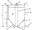
도 1은 축조 재료(11)를 적층 가공 공정에 공급하기 위한 용기(1)의 예의 도식적 정면도를 예시한다. 하나의 예에서, 용기(1)는 용기(1)로부터 축조 재료의 대부분 또는 전부를 수집하기 위해 적층 가공 장치의 수집 시스템 또는 별개의 건축 재료 수집 시스템에 연결될 교체가능한 소스 용기(1)이다. 용기(1)는 고갈 후에 축조 재료를 가진 다른 유사한 용기로 교체되기 위해 적층 가공 장치로부터 분리될 수 있다.Fig. 1 illustrates a schematic front view of an example of a
본 개시의 몇몇 예시적인 용기는 이들 용기 내에 수용된 축조 재료의 효율적인 제거를 용이하게 하기 위한 것일 수 있다. 몇몇 그러한 예시적인 용기는 예를 들어 축조 재료의 대부분 또는 전부가 용기로부터 제거될 수 있는 것을 보장하는 특징부를 포함할 수 있다. 동시에, 용기는 용기가 용이하게 적층, 보관, 수송, 폐기 및/또는 재충전될 수 있는 것을 보장하는 특징부를 포함할 수 있다.Some exemplary containers of the present disclosure may be to facilitate efficient removal of the build material contained in these containers. Some such exemplary containers may include features that ensure, for example, that most or all of the build material can be removed from the container. At the same time, the container can include a feature that ensures that the container can be easily stacked, stored, transported, discarded and / or refilled.
용기(1)는 직립 배향, 예를 들어 용기가 수집 시스템에 연결될 예정이고 축조 재료가 용기 내의 중력 작용의 더 낮은 지점으로 이동하도록 의도되는 배향으로 예시된다. 하나의 예에서, 축조 재료는 예를 들어 상기에 기술된 바와 같은 유형 및/또는 입자 크기를 갖는 분말이다. 용기(1)는 축조 재료(11)를 수용하기 위한 저장소(reservoir)(3)를 포함한다. 축조 재료는 저장소(3)의 벽에 의해 수용된다. 용기(1)는 축조 재료가 저장소(3) 밖으로 나가도록, 또는 필요한 경우 저장소(3) 내로 들어가도록 허용하는 개구를 포함하는 출구 구조체(13)를 추가로 포함한다. 도 1에 예시된 예에서, 출구 구조체(13)는 용기(1)의 상단부 측(15)에 또는 그 부근에 제공된다. 출구 구조체(13)는 용기(1)로부터 축조 재료를 수집할 대응하는 수집 시스템과 협력하도록 구성된다. 용기(1)의 제 1 사용에서, 용기(1)는 미사용 축조 재료를 수용할 수 있다.The
저장소(3)는 또한 적어도 하나의 수렴 측벽(21)을 갖는 깔때기형 하부 부분을 포함한다. 저장소(3)는 깔때기(7) 위에 있는, 적어도 하나의 비-수렴 측벽(19)의 상부 부분(5)을 포함한다. 하나의 예에서, 상부 및 하부 부분(5, 7)은 단일의, 실질적으로 단일체의 저장소 벽 구조체의 부분이다. 직립 배향에서, 비-수렴 측벽은 깔때기(7)로부터 높이(h)의 대부분을 따라 상향으로 연장된다. 상이한 예에서, 상부 부분(5)은 하나의 둥근 비-수렴 벽, 또는 직선 또는 둥근 모서리를 갖는 직사각형을 형성하는 4개의 직선 벽을 가질 수 있다. 이 예에서, 4개의 비-수렴 측벽(19)을 갖는 직사각형 버전을 논의할 것이다.The
예에서, 비-수렴 상부 벽(19)은, 예를 들어 제조 허용오차(tolerance), 이형각(mold release angle), 저장소의 열 경화, 또는 다른 이유 때문에, 용기(1)의 상기 직립 배향에서, 수직과는 차이가 있다. 예를 들어, 비-수렴 벽은 수평(H)으로부터 대략 85 내지 95도의, 또는 약간 불룩한 파형(외향 또는 내향) 형상의 각도(α)를 가질 수 있다. 하나의 예에서, 상대적 비-수렴 측벽(19)의 수평(H)에 대한 각도(α)는 수평(H)에 대한 깔때기(7)의 수렴 측벽(21)의 각도(β)보다 평각(straight angle)에 더 가까워야 한다.In the example, the non-converging
하나의 예에서, 깔때기(7)의 수렴 측벽(21)의 수평에 관한 대략적인 각도(β)는 대략 10 내지 대략 70도, 또는 20 내지 대략 60도일 수 있다. 비-수렴 측벽(19)은 어느 정도 수렴할 수 있지만, 깔때기형 부분의 수렴 벽(21)만큼 많이 수렴하지는 않는다. 하나의 예에서, 깔때기(7)의 상단 또는 상부 부분(5)의 하단에서의 용기(1)의 폭은 상부 부분(5)의 상단에서의 용기(1)의 폭과 대략 동일하다. 비-수렴 상부 부분(5)은 효율적인 축조 재료 저장을 허용할 수 있는 반면, 깔때기(7)는 효율적인 축조 재료 회수를 허용할 수 있다.In one example, the approximate angle? About the horizontal of the converging
도 2a는 상부 부분(5A)의 벽(21A)은 파형 형상을 갖는 반면, 하부의 깔때기형 부분(7A)은 하단(9A)으로 수렴하는, 본 개시의 예시적인 용기(1A)를 예시한다. 상부 부분(5A)은 파형 형상 때문에 국부적으로 약간의 전환을 보일 수 있지만, 깔때기(7A)의 상단 또는 상부 부분(5A)의 하단에서의 용기(1A)의 폭은 상부 부분(5A)의 상단(15A)에서의 용기(1A)의 폭과 대략 동일하다. 깔때기(7A)는 분명히 하단까지 수렴하는 측벽(21A)을 갖는다. 따라서, 상부 부분을, 깔때기(7A)와 비교해, 상대적 비-수렴 측벽(19A)을 갖는 상대적 비-수렴 부분(5A)으로 지칭한다.2A illustrates an
도 1의 예로 되돌아가, 저장소(3)의 하부 부분은 깔때기(7)이고, 적어도 하나의 수렴 측벽(21)을 포함한다. 깔때기(7)는 절두형(truncated) 및/또는 둥근 하단부(9)를 가질 수 있으며, 그것 상에서 수렴 벽(21)이 종료된다. 상이한 예에서, 깔때기(7)는 하나의 둥근 측벽을 포함할 수 있거나, 측벽(21) 사이의 뾰족한 또는 둥근 경계를 갖는 4개의 수렴 측벽(21)의 직사각형 단면을 가질 수 있다. 여기서, 4개의 수렴 측벽(21)의 뒤집힌 피라미드-형상의 깔때기(7)를 논의할 것이다. 피라미드형 깔때기(7)는 동일 직경의 원추형(둥근) 깔때기(7)보다 많은 축조 재료 저장을 허용할 수 있다.1, the lower part of the
깔때기형 벽(21)의 경사도(β)는 축조 재료가 중력의 도움으로 하단부(9)를 향해 낙하하거나 활주하고, 이에 의해 축조 재료가 하단부(9)로부터 수집될 수 있는 것을 용이하게 하도록 선택될 수 있다. 예를 들어, 수평(H)에 대한 깔때기형 벽의 경사도(β)는 대략 60 내지 대략 20도일 수 있다. 하나의 예에서, 깔때기(7)의 수렴 벽(21)은 비교적 직선이다. 다른 예에서, 깔때기 벽(21)은 또한 적어도 부분적으로 둥글 수 있고/있거나, 예를 들어 적어도 부분적으로 상기 범위 내의, 수평(H)에 대한 상이한 경사도를 포함할 수 있다. 수렴 벽(21)은 저장소(3)의 부분적으로 비어 있는 또는 작동 상태에서 적어도 부분적으로 휘어질 수 있으며; 벽(21)은 저장소(3)의 내부에 압력이 인가되기 전에, 인가되는 동안, 또는 인가된 후에, 주름, 만곡, 리지(ridge), 파형 형상 등을 포함할 수 있다. 수렴 벽(21)은 축조 재료(11)를 하단부(9)를 향해 안내할 수 있으며, 이 하단부로부터 축조 재료(11)가 각자의 적층 가공 장치로의 전달을 위해 쉽게 수집될 수 있으며, 이에 의해 저장소(3)로부터의 축조 재료의 대부분 또는 전부의 수집을 용이하게 할 수 있다.The inclination beta of the funnel-shaped
저장소(3)는 적어도 부분적으로 가요성인 재료로 제조될 수 있다. 예를 들어, 저장소(3)는 비어 있는 상태에서 절첩될 수 있고, 벽은 저장소(3)의 부분적으로 비어 있는 또는 작동 상태에서 휘어질 수 있고, 벽(19, 21)은 주름, 만곡, 리지, 파형 형상 등을 포함할 수 있다. 예를 들어, 상부 부분(5)의 직립 벽은 용기(1)의 비절첩 충전된 상태에서 실질적으로 직립인 디폴트 배향을 갖는다. 다른 예에서, 저장소(3)는 비교적 강성, 또는 부분적으로 비교적 강성 및 부분적으로 비교적 가요성일 수 있다.The
하나의 예에서, 비교적 가요성은 벽 재료의 구부림을 허용하는 것으로 이해될 수 있는 반면, 강성 재료는 구부림 또는 신장(stretching)에 저항하는 것으로 이해되어야 한다. 가요성 재료 또는 화합물은 탄성, 예를 들어 PE 또는 다른 중합체 기반 재료일 수 있거나, 비-탄성, 예를 들어 증기 장벽 층(vapor barrier layer)을 포함하는 필름 층을 포함한 마일라(Mylar) 또는 다른 재료일 수 있다. 하나의 예에서, 가요성 및 탄성 벽 재료는 대략 1 * 109 N/m2 GPa 미만, 또는 대략 0.3 * 109 N/m2 GPa 미만의 영률(Young's modulus)을 갖는다. 하나의 예에서, 비교적 강성 또는 비-탄성 벽 재료는 대략 1 * 109 N/m2 GPa 초과의 영률을 갖는다.In one example, relatively flexibility may be understood as allowing bending of the wall material, while it should be understood that the rigid material is resistant to bending or stretching. The flexible material or compound may be elastic, e.g., PE or other polymer-based material, or may be a non-elastic, e.g., Mylar, or other material, including a film layer comprising a vapor barrier layer. Lt; / RTI > In one example, the flexible and resilient wall material has a Young's modulus of less than about 1 * 10 9 N / m 2 GPa, or less than about 0.3 * 10 9 N / m 2 GPa. In one example, a relatively stiff or non-elastic wall material has a Young's modulus of greater than about 1 * 10 9 N / m 2 GPa.
하나의 예에서, 축조 재료(11)는 수집 유닛(17)의 도움으로 하단부(9)로부터 수집되도록 의도된다. 예시된 예에서, 수집 유닛(17)은 상단부 출구 구조체(13)의 상단부 개구로부터 하단부(9)까지 연장된다. 하나의 예에서, 수집 유닛(17)은 관일 수 있는데, 이 관은 외부 압력 유닛을 통해 이 관에 진공을 가함으로써 하단부(9)로부터 축조 재료를 흡입한다. 외부 압력 유닛은 축조 재료를 빨아올리도록 저장소에 음압을 생성할 수 있거나, 그것이 충전 모드로 전환되는지 또는 흡입 모드로 전환되는지에 따라, 음압과 양압을 생성하도록 구성될 수 있다. 다른 예에서, 수집 유닛(17)은 축조 재료를 회수하기 위한 스크류 또는 나선-유형 수송 메커니즘을 포함할 수 있다.In one example, the
수집 유닛(17)은 용기(1)의 부분 또는 외부 수집 시스템의 부분일 수 있다. 그것이 용기(1)의 부분인 경우, 수집 유닛(17)은 외부 축조 재료 수집 시스템에 연결가능할 수 있다. 그것이 용기(1)의 부분인 경우, 수집 유닛(17)은 용기(1)의 출구 구조체(13)의 부분이며, 이에 의해 축조 재료가 출구 구조체(13)를 통해 수집 유닛(17)에 연결되는 외부 수집 시스템의 도움으로 하단부(9)로부터 수집된다. 예를 들어, 수집 유닛(17)은 관이고 수집 시스템은 압력 유닛을 포함하며, 이에 의해 축조 재료가 압력 유닛에 의해 수집 유닛(17) 내로 흡입된다.The
수집 유닛(17)이 외부 수집 시스템의 부분인 예에서, 그것은 축조 재료를 회수하기 위해 저장소(3) 내로 삽입되도록 의도된다. 그러한 외부 수집 유닛(17)은 출구 구조체(13)를 통해 삽입될 수 있다.In the example in which the
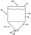
다른 예시적인 용기(1B)가 도 2b에 예시된다. 도 2b의 용기(1B)는 도 1의 용기(1B)와 유사하다. 용기(1B)는 상부 비-수렴 부분(5B) 및 하부 깔때기(7B)를 갖는다. 분말이 중력을 통해 저장소(3B)를 빠져나갈 수 있는 것을 용이하게 하기 위해 출구 구조체(13B)는 하단부(9B)에 제공된다.Another
도 1, 도 2a 및 도 2b에 예시된 예에서, 저장소(3, 3A, 3B)의 상부 비-수렴 부분(5, 5A, 5B)은 하단부(9, 9A, 9B)와 상단부(15) 사이에서 측정될 때 저장소(3, 3A, 3B)의 높이(h)의 대부분에 걸친다. 예를 들어, 상부 부분(5, 5A, 5B)은 하단부(9, 9A, 9B)와 상단부(15, 15A, 15B) 사이에서 측정될 때 저장소(3, 3A, 3B)의 높이(h)의 적어도 50%, 적어도 60%, 적어도 70%, 적어도 80%, 또는 적어도 90%에 걸친다. 상부 부분(5, 5A, 5B)은 주어진 폭 또는 직경의 용기(1, 1A, 1B) 내에 상대적으로 많은 체적의 축조 재료를 저장하는 것을 용이하게 한다. 저장소(3, 3A, 3B)의 더 작은 하단부 부분만이 깔때기형이다. 하나의 예에서, 하단부 부분의 5% 내지 40%, 5% 내지 30%, 5% 내지 20%, 또는 5% 내지 10%가 깔때기형이다. 따라서, 용기(1, 1A, 1B)가 미사용 분말의 교체가능한 공급부인 경우, 많은 충전된 용기(1, 1A, 1B)가 수송을 위해 수직 및 수평으로 적층될 수 있으며, 이에 의해 적층된 용기(1, 1A, 1B)에 의해 소비되는 총 공간 중 비교적 많은 양이 축조 재료에 의해 점유된다. 동시에, 깔때기(7, 7A, 7B)는 하단부(9, 9A, 9B)로부터 축조 재료를 수집함으로써 적층 가공 동안 이들 용기(1, 1A, 1B)를 쉽게 비우는 것을 용이하게 한다. 용기(1, 1A, 1B)는 비움 후에 교체될, 교체가능한 공급부로서의 역할을 할 수 있다.In the example illustrated in Figures 1, 2A and 2B, the upper
상이한 예에서, 축조 재료 저장소(3)는 예를 들어 대략 5 내지 대략 70 리터, 대략 10 내지 대략 60리터, 예를 들어 대략 30 리터의 축조 재료 체적을 수용하도록 의도된다. 이들 체적과 연관된 중량은 축조 재료, 분말 알갱이 크기 등에 의존할 수 있다. 이들 체적을 수용하는 예시적인 용기(1)는 대략 700 mm 이하, 대략 650 밀리미터 이하의 높이를 가질 수 있으며, 예를 들어 대략 400 mm 이하의 폭을 가질 수 있다. 이들 치수 및 연관된 중량은 예를 들어 용기(1)를 수동으로 들어올리고, 적층하고, 이동시키는, 작업자에 의한 용기(1)의 손쉬운 취급을 허용할 수 있다. 또한, 용기(1)는 비어 있는 상태에서 절첩, 적층 및/또는 폐기되도록 구성될 수 있다.In a different example, the build-up
소정 예에서, 용기(1)는 예를 들어 50 리터 초과, 예를 들어 적어도 대략 100, 150 또는 200리터와 같은 더 큰 축조 재료 체적을 가질 수 있다.In certain instances, the
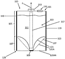
도 3은 적어도 부분적으로 가요성인 저장소(103) 및 저장소(103)의 적어도 부분을 지지하는 보강 구조체(123)를 포함하는 3D 프린팅 축조 재료 용기(101)를 예시한다. 축조 재료가 저장소(103)를 빠져나가는 것을 허용하기 위해 제 1 개구를 갖는 출구 구조체(113)가 저장소(103)의 상단부 벽(115)에 제공된다. 저장소(103)를 통한 제 2 개구를 포함하는 스루풋 구조체(throughput structure)(135)가 상단부 벽(115)에 제공되며, 통기구(vent)로서 기능할 수 있다. 예시된 예에서, 저장소(103)는 압력하에서 적어도 부분적으로 구부러지고/구부러지거나 신장될 수 있는, 비교적 가요성인 재료의 적어도 하나의 벽(121)을 포함한다. 예를 들어, 저장소(103)는 비어 있는 상태에서 수송, 보관 또는 폐기를 위한 찌부러짐(collapsing)을 용이하게 하기 위해, 그리고/또는 축조 재료의 유동을 용이하게 하기 위해 적어도 부분적으로 가요성이다.3 illustrates a 3D printing building material container 101 that includes an at least partially
보강 구조체(123)는 적어도 부분적으로 가요성인 저장소(103)를 보강하도록 의도된다. 보강 구조체(123)의 벽은 가요성 재료의 벽보다 강성이다. 보강 벽은 휨 또는 구부림에 저항하도록 의도된다. 보강 구조체(123)는 용기(101)의 상단부(115)로부터 하단부(109)까지 연장되는 벽(125)을 포함할 수 있다. 보강 구조체(123)는 상이한 단면 또는 구멍을 포함할 수 있다. 보강 구조체(123)는 일반적으로 단일 재료의 것일 수 있다. 보강 구조체(123)는 용기(101)의 기부(129) 또는 적어도 하나의 풋(foot)을 형성할 수 있으며, 이에 의해 깔때기(107)가 기부(129)를 형성하는 보강 벽 사이에서 연장될 수 있다. 하나의 예에서, 보강 구조체(123)는 충전된 용기 수송 및/또는 축조 재료 회수 동안 저장소(103)의 소정 벽 부분을 사전결정된 형상으로 유지하도록 의도된다. 예를 들어, 저장소(103)는 플라스틱 또는 다층 증기 장벽 재료를 포함하는 적어도 부분적으로 가요성인 백(bag)을 포함하며, 보강 구조체(123)는 판지, 금속 또는 비교적 강성인 화합물과 같은 절첩가능한 재료를 포함한다.The
하나의 예에서, 보강 구조체(123)는 판지 절첩 구조체 및 금속 와이어프레임(wireframe) 중 하나만을 포함한다. 다른 예에서, 보강 구조체(123)는 판지 절첩 구조체 및 금속 와이어프레임을 포함한다. 다른 예에서, 보강 구조체(123)는 성형된 또는 압출된 플라스틱을 포함할 수 있고, 저장소와 별개이거나 일체일 수 있다.In one example, the
하나의 예에서, 저장소(103)의 4개의 비-수렴 측벽(119) 및 4개의 수렴 하단부 벽(121) 모두는 가요성이다. 보강 구조체(123)는 저장소(103)의 외측 에지를 따라 그리고 그것의 외부에서 연장된다. 가요성 저장소 벽(119, 121)의 부분은 외측 보강 구조체(123)에 부착된다. 이에 의해, 보강 구조체(123)는 가요성 저장소(103)를 지지한다.In one example, both the four
하나의 작동 모드에서, 출구 구조체(113)에 진공 시스템을 연결함으로써 진공(F)이 저장소(103)에 가해진다. 이에 의해, 축조 재료는 출구 구조체(113)를 통해, 저장소(103) 밖으로 빨아내진다. 저장소(103)에 가해진 진공 때문에, 적어도 부분적으로 가요성인 하부 부분(107)의 하부 벽(121)은 상기 진공(F)의 결과로서 하부 벽(121)을 내향으로 구부림으로써 예시된 바와 같이 내향으로 불룩할 수 있다.In one mode of operation, the vacuum F is applied to the
그러나, 저장소(103)의 비-작동, 충전된 상태에서, 하부 벽(121A 또는 121AA)은 디폴트 직선 형상을 가질 수 있다. 하나의 예에서, 하부 부분(107)은 깔때기형 하단부를 형성하도록 경사진 수렴 벽(121A)을 포함할 수 있다. 다른 예에서, 벽(121AA)은 비교적 평평한 하단부를 형성할 수 있으며, 여기서 벽(121B)은, 선(121)에 의해 예시된 바와 같이, 깔때기형 형상을 형성하도록, 진공 압력하에서 내향으로 불룩하다.However, in the non-actuated, filled state of the
보강 구조체(123)에 부착되지 않은 저장소(103)의 임의의 가요성 벽 재료는 진공이 가해질 때 형상을 변경할 수 있다. 예를 들어, 가요성 벽은 진공이 출구 구조체(113)에 가해질 때 진동하거나, 구부러지거나, 휘거나, 신장되거나, 주름지거나 등등을 할 수 있다. 벽 이동 및 변형은 축조 재료를 하단부(109)에 있는 수집 영역을 향해 이동시키는 것을 도울 수 있다. 벽 이동은 축조 재료의 교반, 혼합 및/또는 회수를 도울 수 있다. 예시된 예시적인 용기(101)는 하단부(109) 부근에 있는 수집 영역으로부터 축조 재료(111)를 수집하고 이것을 출구 구조체(113)를 통해 저장소(103) 밖으로 안내하기 위해, 상단부(115)에 있는 출구 구조체(113)로부터 하단부(109) 부근까지 연장되는 종방향 수집 유닛(117)을 추가로 포함한다.Any flexible wall material of the
보강 구조체(123)는 저장소(103)의 소정 부분을 전략적으로 보강하면서 가요성 부분이 휘도록 허용할 수 있다. 보강 구조체(123)는 가요성 벽 재료가 축조 재료를 수집 영역으로부터, 예를 들어 가요성 벽 내의 포켓(pocket) 내에 격리시킬 수 있는 것을 억제할 수 있다. 하나의 예에서, 보강 구조체(123)는 저장소(103)의 2개의 서로 반대편에 있는 비-수렴 측벽(119)을 보강하면서, 부착되지 않은 2개의 다른 비-수렴 측벽(119)이 내향으로 구부러지도록 허용한다. 하나의 예에서, 보강 구조체(123)는 모든 4개의 수렴 하단부 벽(121)의 적어도 부분을 보강한다. 다른 예에서, 보강 구조체(123)는 2개의 서로 반대편에 있는 수렴 하단부 벽(121)을 보강하면서, 2개의 다른 서로 반대편에 있는 수렴 벽(121)이 내향으로 구부러지도록 허용한다.The
가요성 저장소 벽(119, 121)은 비교적 탄성이거나 비교적 비-탄성일 수 있다. 비교적 탄성인 저장소 벽의 예는 폴리에틸렌 또는 박벽(thin-walled) PET로 제조될 수 있다. 비-탄성 가요성 벽 재료의 예는 금속 필름 층을 포함한다. 탄성 벽 재료는 대략 1 * 109 N/m2 GPa 미만, 또는 대략 0.3 * 109 N/m2 GPa 미만의 영률을 가질 수 있다. 보강 벽 재료는 대략 1 * 109 N/m2 GPa 초과의 영률을 가질 수 있다.The
저장소 벽(119, 121, 109, 115)은 예를 들어 축조 재료의 저하를 억제하기 위해 비교적 낮은 기체/증기 투과성을 갖는 증기 및/또는 기체 장벽을 형성할 수 있다. 가요성 저장소의 예에서, 벽 재료는 금속화된 장벽 필름 또는 중합체 장벽 재료, 예를 들어 마일라, 폴리에틸렌(PE), 박형 PET를 각각 포함할 수 있다.The
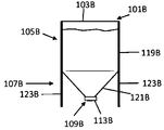
도 3b는 적어도 부분적으로 가요성인 저장소(103B)를 갖는 용기(101B)의 예를 예시한다. 용기(101B)는, 예를 들어 중력 공급식 축조 재료 분배를 용이하게 하기 위해 출구 구조체(113B)가 하단부(109B)에 제공된 것을 제외하고는, 도 3의 용기(101)와 유사한 특성을 갖는다. 용기(101B)는 보강 구조체(123B)를 포함할 수 있다. 하나의 예에서, 보강 구조체(123B)는 상부 부분(105B)을 따라 적어도 부분적으로 가요성인 저장소(103B)를 지지할 수 있다. 예를 들어, 보강 구조체(123B)는 상부 부분의 적어도 2개의 서로 반대편에 있는 벽에 부착될 수 있다. 보강 구조체(123B)는 깔때기형 부분(107B) 및 출구 구조체(113B)가 하단부(109B)를 향한 상태로 용기(101B)가 직립 방식으로 서 있는 것을 허용하도록 용기(101)의 기부를 형성할 수 있다. 예에서, 저장소(103B)는 가요성 플라스틱 백에 의해 형성될 수 있고, 보강 구조체(123B)는 판지로 형성될 수 있다.3B illustrates an example of a
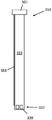
도 4는 축조 재료 저장소(203)를 포함하는, 축조 재료(211)를 위한 다른 예시적인 용기(201)를 예시한다. 저장소(203)는 적어도 부분적으로 가요성일 수 있다. 용기(201)에는 보강 구조체(223, 223A)가 제공될 수 있다. 보강 구조체(223, 223A)는 저장소(203)의 외부를 따라 제공될 수 있고, 저장소(203)를 지지하기 위해 저장소(203)의 부분에 부착될 수 있다. 보강 구조체(223, 223A)는 저장소(203)를 지지하기 위한 내측 지지 구조체(223), 및 내측 지지 구조체(223) 주위의 외측 쉘 구조체(223A)를 포함할 수 있다. 외측 쉘 구조체(223A)는 하단부 보호, 디스플레이 영역, 추가의 지지 등을 제공할 수 있다.4 illustrates another
용기(201)는 상부 부분(205) 및 하부 부분(207) 또는 깔때기를 가지며, 여기서 상부 부분(205)은 비-수렴하는, 예를 들어 실질적으로 직립인, 벽(219)을 포함하고, 용기(201)의 높이(h)의 대부분을 덮는다. 용기는 축조 재료(211)가 상단부 측(215)으로부터 저장소(203)를 빠져나가는 것을 허용하기 위해 상단부 측에서 출구 개구(231)를 갖는 출구 구조체(213)를 포함한다. 출구 구조체(213)는 진공 흡입에 의해 저장소(203)로부터 축조 재료를 회수하는 것을 용이하게 하기 위해, 진공 소스와 같은, 외부 압력 유닛에 연결하기 위한 어댑터(251)를 포함할 수 있다.The
예시된 예에서, 하부 부분(207)은 중력 및/또는 압력 유닛에 의해 생성되는 압력의 영향하에서 저장소(203)의 하단부(209)에 있는 중심 수집 영역을 향해 축조 재료를 안내하도록 깔때기형이다. 깔때기는 경사진 수렴 벽(221)에 의해 형성된다.In the illustrated example, the
용기(201)는 하단부(209)로부터 축조 재료를 수집하기 위해 상단부(215) 부근으로부터 하단부(209)까지 연장되는 종방향 수집 유닛(217)을 포함한다. 수집 유닛(217)은 출구 구조체(213)의 고정된 또는 분리가능한 부분을 형성할 수 있다. 수집 유닛(217)은 하단부(209)에 있는 수집 영역으로부터 축조 재료를 수집하고, 상단부(215)에 있는 출구 개구(231)를 통해 축조 재료를 밖으로 안내하도록 의도된다. 하나의 예에서, 수집 유닛(217)은 적어도 부분적으로 관-형상이다. 관-형상의 유닛(217)은 상단부(215)에 있는 출구 개구(231)로부터 저장소(203)의 중심 하단부(209)까지 연장된다. 수집 유닛(217)은 깔때기(207)의 하단부(209)로부터 축조 재료를 수집하기 위해 비-수렴하는, 예를 들어 직립의, 상부 부분(205)을 따라, 그리고 깔때기(207) 내로 연장된다. 수집 유닛(217)은 강성 관(233) 또는 가요성 호스일 수 있다.The
하나의 예에서, 수집 유닛(217)은 그것의 관(233)을 통한 진공 흡입을 용이하게 하도록 의도된다. 그러한 예에서, 출구 구조체(213)의 어댑터 부분(251)은 적층 가공 장치의 압력 유닛에 연결하도록 배열되어, 압력 유닛이 출구 구조체(213)에 연결되고 스위치 온될 때, 축조 재료(및 공기) 유동이 관(233)을 통해 상향 방향(F)으로 확립된다.In one example, the
예에서, 용기(201)는 진공 흡입 동안 저장소(203) 내로 공기를 통기시키는 것을 용이하게 하기 위해 출구 구조체(213) 옆에 상단부 벽(215) 내에 스루풋 구조체(235)를 포함한다. 다른 예에서, 저장소(203)는 적어도 부분적으로 가요성이며, 이에 의해 상기 진공 흡입 동안 소정의 벽 부분이 내향으로 휘어지고/휘어지거나 진동할 수 있다. 추가의 예에서, 예를 들어 저장소(203)를 충전하거나 플러싱(flushing)할 때, 압력 유닛은 저장소(203)에 양압을 인가할 수 있다.In an example, the
하나의 예에서, 저장소(203)는 대략 5 내지 70 리터의 내부 체적을 갖고, 관(233)은 대략 40 내지 65 센티미터의, 출구 개구(231)와 원위 단부(distal end)(241) 사이의 길이를 가질 수 있다. 관(233)은 대략 10 내지 70 밀리미터, 예를 들어 대략 25 내지 60 밀리미터의 직경을 가질 수 있다.In one example, the
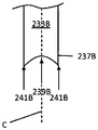
축조 재료는 관의 원위 단부 부분(237)에서 관(233)에 들어가도록 의도된다. 단부 부분(237)은 하단부(209)로부터 축조 재료를 추출하기 위해 하단부(209) 부근으로 연장된다. 추가의 예에서, 단부 부분(237)은 하단부(209)에 접촉하며, 이에 의해 관(233)은 예를 들어 보강 구조체(223)에 더하여 추가의 구조적 보강을 용기(201)에 제공할 수 있다. 단부 부분(237)은 적어도 하나의 입구 또는 흡입 개구(239)를 포함하며, 이것을 통해 축조 재료가 들어가도록 의도된다. 하나의 예에서, 단부 부분(237)은 다수의 그러한 흡입 개구(239)가 그것들 사이에서 연장되는 나사산(thread) 또는 표면을 포함한다. 예에서, 단부 부분(237)은 원치 않는 입자가 수집 시스템에 제공되는 것을 억제하기 위해 필터를 포함할 수 있다.The build material is intended to enter the
하나의 예에서, 관(233)의 단부 부분(237)은 측방향 개구(239)를 포함하며, 이에 의해 작동 시에 축조 재료가 적어도 부분적으로 측방향(L)으로 관(233)에 들어간다. 단부 부분(237)은 캡(cap) 또는 나사산과 같은 원위 단부 구조체(241)를 추가로 포함할 수 있다. 예에서, 원위 단부 구조체(241)는 저장소 하단부(209)와 맞물린다. 측방향 개구(239)는 적어도 부분적으로 원위 단부 구조체(241) 위로 연장되어, 작동 시에 축조 재료가 원위 단부 구조체(241) 위에서, 측방향으로 관(233)에 들어간다. 원위 단부 구조체(241)는 하단부 벽 부분이 흡입 개구(239)를 차단하는 것을 방지할 수 있다.In one example, the
도 4b는 축조 재료 진공 관(233B)의 단부 부분(237B)의 다른 예를 정면 단면도로 예시한다. 관(233B)은 중심축(C)을 갖는다. 단부 부분(237B)은 예를 들어 저장소 하단부와 맞물리기 위해 관(233)의 최저 지점을 한정하는 원위 단부 구조체(241B)를 포함한다. 측방향 개구(239B)는 원위 단부 구조체(241B) 위에 축조 재료 진입 지점을 제공한다. 예시된 예에서, 측방향 개구(239B)는 관(233B)의 단부에 있는 단일의 일체형 관 단부 개구의 부분이다.Fig. 4B illustrates another example of the
도 4의 용기(201)는 통기를 용이하게 하는 공기/축조 재료 스루풋 구조체(235)를 추가로 포함한다. 스루풋 구조체(235)는 저장소(203)의 상단부 벽(215)에 또는 그 부근에, 출구 구조체(213) 옆에 제공된다. 통기에 더하여, 스루풋 구조체(235)는 작업자가 (i) 저장소(203)에 축조 재료를 추가하고/하거나, (ii) 저장소(203) 밖으로 축조 재료를 부을 수 있게 하도록 구성된다. 따라서, 스루풋 구조체(235)는 하나의 모드에서 공기가, 그리고 다른 모드에서 축조 재료가 통과하도록 허용하기 위해 저장소를 통한 개구(243)를 포함한다. 상단부 벽(215)에 스루풋 구조체(235)를 갖는 것은, 또한 저장소(203)가 상단부까지 충전될 때, 통기를 용이하게 한다. 스루풋 구조체(235)는 저장소(203)의 측방향 측벽(219)과 출구 구조체(213) 사이에, 예를 들어 출구 구조체(213)로부터 거리를 두고서, 저장소(203)의 측방향 측벽(219)에 비교적 가까이에 위치될 수 있다. 측벽(219) 가까이의 위치는 저장소(203)로부터 직접 축조 재료를 붓는 것을 용이하게 한다.The
스루풋 구조체(235)는 통기 모드에서 축조 재료를 보유하면서 공기가 통과하도록 허용하기 위해, 개구(243)를 덮는 필터(245)를 포함한다. 스루풋 구조체(235)는 필터(245)를 유지하기 위해 필터 홀더(247)를 포함한다. 필터(245)를 가진 필터 홀더(247)는, 축조 재료를 충전하거나 붓기 위해, 축조 재료가 개구(243)를 통과하도록 허용하기 위해서, 저장소(203)로부터 결합 해제될 수 있다. 저장소(203)는 필터 홀더(247)에 대한 연결 및 분리를 위해 플랜지 및 스크류-나사산 형성된 목부(neck)를 가진 개구를 포함할 수 있다. 필터(245)가 없다면, 저장소(203) 밖으로 축조 재료를 붓는 것을 용이하게 하기 위해 축조 재료가 개구(243)를 통해 저장소(203)를 빠져나갈 수 있다. 필터(245)가 없다면, 저장소(203)를 충전하기 위해 축조 재료가 저장소(203)에 들어갈 수 있다.The
출구 구조체(213) 및 스루풋 구조체(235)는 적어도 하나의 적합한 밀봉 구조체, 예를 들어 각각의 각자의 개구(231, 243) 위에 부착되는 밀봉 필름으로 밀봉될 수 있다. 하나의 예에서, 충전된 용기(201)가 그것이 충전 스테이션에서 미사용 축조 재료로 충전된 후에 일회용 시일로 밀봉된다. 또한, 캡 또는 리드(lid)(239)가 출구 구조체(213) 및 스루풋 구조체(235) 각각 위에 제공될 수 있다.The
도 5는 축조 재료 수집 관(333)을 포함하는 출구 구조체(313)의 예를 예시한다. 축조 재료 수집 관(333)은 그것의 원위 단부에서, 적어도 하나의 축조 재료 진공 흡입 개구(339)를 갖는 단부 부분(337)을 포함할 수 있다. 작동 시, 관(333)은 저장소의 하단부로부터 축조 재료를 수집하기 위해 축조 재료 저장소 내로 연장될 수 있다. 관(333)은 관련 외부 압력 유닛에 연결하기 위해 그것의 근위 단부(proximal end)에서 어댑터(351)에 연결된다. 예시된 예에서, 수집 관(333)은 공기 채널(353)을 추가로 포함한다. 공기 채널(353)은 관(333)의 길이를 따라 연장될 수 있다. 공기 채널(353)은 주위 공기와 연통하도록 의도되는 근위 개구(355), 및 저장소의 내부, 예를 들어 저장소 내의 하단부 축조 재료 수집 영역 부근과 연통하도록 의도되는 원위 개구(357)를 포함한다. 하나의 예에서, 출구 구조체(313)의 상단부 부근에 입구를 갖는 공기 채널(353)은, 저장소의 상단부 측에 있는 다른 통기 개구에 더하여(예를 들어, 도 4 참조), 저장소의 하단부에 있는 축조 재료 수집 영역과 주위 공기 간의 통기 연결을 제공할 수 있다. 공기 채널(353)은 하단부(209)로부터 축조 재료를 손쉽게 수집하는 것을 촉진할 수 있는데, 예를 들어 하단부(209) 부근에 난류를 생성하는 것을 도울 수 있다.Fig. 5 illustrates an example of an
공기 채널(353)은 관(333)에 일체일 수 있다. 하나의 예에서, 하나 이상의 공기 채널(353)이 관(333)의 진공 채널 옆에서, 관(333) 내의 진공 채널에 평행하게 연장된다. 다른 예에서, 공기 채널(353)은 관(333) 내의 진공 채널에 동심으로, 즉 진공 채널의 적어도 일부 주위에 연장되며, 이에 의해 관(333)은 중심축 주위에 2개의 동심 관형 벽을 포함한다.The
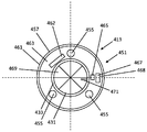
도 6 내지 도 8은 출구 구조체(413) 및 관련 압력 유닛(459)의 어댑터 부분의 도식을 예시한다. 도 6은 출구 구조체(413)의 도식적 평면도를 예시한다. 도 7은 출구 구조체(413)와 관련될 외부 압력 유닛(459)의 단부 부분의 도식적인 부분 측단면도를 예시한다. 도 8은 출구 구조체(413)의 도식적 측단면도를 예시한다.6-8 illustrate schematics of the
출구 구조체(413)는 압력 유닛(459)에 연결하기 위해 어댑터(451)를 포함한다. 출구 구조체(413)는, 예를 들어 어댑터(451)의 하단부로부터 저장소 내로 저장소 하단부(409)까지 하향 돌출하는 출구 관(433)을 통해, 저장소의 내부에 대한 접근을 제공하기 위해 그것의 중심에서 출구 개구(431)를 포함한다.The
예시된 예에서, 어댑터(451)는 관(433)보다 넓다. 어댑터(451)는 어댑터(451)의 인터페이스 면(interface face)(463)의 외측 에지(461)를 따른 적어도 하나의 직립 벽(457)을 포함한다. 직립 벽(457)은 단일 원형의 원주방향 벽일 수 있다. 직립 벽(457)은 대응하는 압력 유닛(459)의 대응하는 어댑터(475)를 상호연결로 안내하는 역할을 할 수 있다.In the illustrated example, the
관(433)의 내측 벽은 제 1 안내 특징부로서 기능할 수 있는데, 왜냐하면 그것은 압력 스나우트(473)를 출구 구조체(413) 내로 안내하기 때문이다. 직립 벽(457)은 제 2 안내 특징부로서 기능할 수 있는데, 왜냐하면 그것은 압력 유닛 어댑터(475)를 출구 구조체(413) 내로 안내할 수 있기 때문이다. 직립 벽(457)은 공기/축조 재료 유동 방향(A)으로 돌출한다. 압력 유닛(459)은 원주방향 직립 벽(457)의 벽 내에, 또는 그 주위에 끼워맞춤될 수 있다.The inner wall of the
인터페이스 면(463)은 공기/축조 재료 유동 방향(A)에 직교하여, 직립 벽(457) 내에서, 출구 개구(431) 주위에 환형으로 연장된다. 몇몇의 인터페이스 요소가 환형 인터페이스 면(463) 내에 제공될 수 있다. 하나의 예에서, 제 3 안내 특징부로서의 역할을 할 수 있는, 디지털 상호연결 포켓(468)과 같은, 소정의 추가의 안내 특징부가 압력 유닛(459)을 출구 구조체(413)로 안내하고 그것에 결합하는 것을 돕기 위해 인터페이스 면(463) 내에 제공될 수 있다. 다시, 추가의 안내 특징부는 압력 유닛(459)의 대응하는 돌출부를 안내하도록 의도되는 안내 슬롯(guide slot)(462), 또는 반대로 압력 유닛(459) 내의 대응하는 슬롯을 안내하는 안내 돌출부일 수 있다.The
어댑터(451)는 인터페이스 면(463) 내에 적어도 하나의 자기적 안내 특징부(455) 또는 다른 추가의 안내/래치(latch) 특징부를 포함할 수 있다. 자기적 안내 특징부(455)는 외부 압력 유닛(459) 내의 대응하는 자기적 요소를 끌어당기기 위해, 자성 금속 또는 자석과 같은, 적어도 하나의 자기적 요소를 포함한다. 자기적 안내 특징부(455)는 압력 유닛(475)의 자기적 요소(483)가 자기적 안내 특징부(455)에 근접한 때 압력 유닛 어댑터(451)를 끌어당기도록 의도된다. 자기적 안내 특징부(455)는 스나우트(473)를 최종 상호연결된 상태로 끌어당길 수 있으며, 이에 의해 자기적 안내 특징부(455)의 인력(attraction force) 및 후속의 클릭킹 음(clicking sound)은 출구 구조체(413)와 스나우트(473)가 적절히 연결되었다는 피드백을 작업자에게 제공할 수 있다. 자기적 끌어당김은 또한 상호연결된 스나우트(473)와 출구 구조체(413) 간의 소정 수준의 보유력(retention force)을 제공할 수 있다. 스나우트(473)와 어댑터(451)의 보유는 진공 흡입력에 의해 추가로 도움을 받는다. 자기적 안내 특징부(455)가 압력 유닛(459)을 끌어당기기 위해, 어댑터(451)와 스나우트(473)는 서로에 관하여 적절한 회전 배향을 가질 필요가 있다. 자기적 안내 특징부(455)는, 예를 들어 먼지가 많은 환경에서 잘 작동할 수 있는, 강건하고 사용자 친화적인 상호연결을 촉진할 수 있다.The
출구 구조체(413)의 다른 안내 특징부는 돌출부, 레일(rail), 노치(notch), 슬롯 등을 포함할 수 있으며, 예를 들어 상호연결 구조체의 암형 또는 수형 요소가 둘 모두의 상호연결 어댑터(451, 475) 상에 제공될 수 있다. 더욱이, 또한 압력 유닛이 턴 온되지 않은 때, 어댑터(451)와 압력 유닛(459)이 예를 들어 후킹(hooking), 래칭(latching), 마찰 등에 의해 결합된 상태로 유지되도록, 클릭 핑거(click finger), 래치, 노치, 마찰 끼워맞춤 요소 등과 같은 보유 특징부가 압력 유닛에 래칭하기 위해 제공될 수 있다. 자기적 안내 특징부(455)가 또한 보유 특징부로서의 역할을 한다.Other guiding features of the
어댑터(451)는 센서 트리거 구조체(sensor trigger structure)(465)를 추가로 포함할 수 있다. 예에서, 트리거 구조체(465)는 압력 유닛(459)의 센서 디바이스를, 예를 들어 광학적으로 또는 기계적으로 트리거하기 위해 환형 인터페이스 면(463)으로부터 돌출한다. 트리거 구조체(465)는 메인 어댑터 구조체와 일체로 성형된 정육면체 또는 원통형 돌출부일 수 있다. 어댑터(451)는 데이터 인터페이스(467)를 추가로 포함한다. 데이터 인터페이스는 인터페이스 면(463) 내에, 예를 들어 인터페이스 면(463)의 포켓(468) 내에 제공될 수 있다. 데이터 인터페이스(467) 자체는 메모리 칩, 마이크로컨트롤러, 집적 회로, 스마트 칩 등의 접촉 패드(contact pad)에 의해 형성될 수 있다. 데이터 인터페이스(467)는 압력 유닛(459) 상에 제공된 대응하는 데이터 인터페이스(487)에 연결하도록 의도된다.The
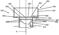
출구 구조체(413)는 출구 개구(431)를 덮는 밸브(469)를 추가로 포함할 수 있다. 밸브(469)는 관(433) 내부로 연장될 수 있다. 밸브(469)는 압력 유닛(459)이 연결되지 않은 때 축조 재료, 예를 들어 분말 가루가 저장소를 빠져나가는 것을 억제하도록 의도된다. 하나의 예에서, 밸브(469)는 (i) 압력 유닛(459)에 의한 출구 구조체(413)에의 충분한 압력, 및 (ii) 출구 구조체(413) 내에 삽입되고 그에 의해 밸브(469)를 밀어 개방하는 외부 어댑터 관 등 중 적어도 하나에 의해 개방되도록 의도된다. 예시된 예에서, 밸브(469)는, 예를 들어 각각 원의 1/4을 형성하고 관(433)의 내측 벽으로부터 돌출하는 4개의 가요성 필름으로 된, 가요성 필름 밸브이다. 도 8은 폐쇄 상태 및 개방 상태에 있는 필름 밸브 필름(469B)을 예시하며, 개방 위치는 점선으로 표시되어 있다. 필름 밸브(469B)는 스나우트(473)의 삽입에 의해 개방되고, 스나우트(473)가 출구 구조체(413)로부터 빼내어질 때 다시 폐쇄 위치로 휘어진다.The
어댑터(451)는 관(433)의 내측 벽으로부터 상향 방향으로 돌출하는 돌출 핑거(471)를 추가로 포함할 수 있다. 예시된 예에서, 핑거(471)는 압력 유닛(459) 내의 대응하는 밸브를 밀어 개방하기 위해 먼저 내측 벽으로부터 멀어지는 쪽으로 돌출하고, 이어서 출구 개구(431)를 향해 상향으로 향한다.The
도 7은 도 6 및 도 8의 출구 구조체(413)와 관련되는 압력 유닛(459)의 단부 부분의 예를 예시한다. 압력 유닛(459)은 적층 가공 장치 또는 별개의 수집 시스템의 부분일 수 있다. 도 7은 압력 유닛(459)의 스나우트(473), 어댑터(475) 및 관(477)의 예를 예시한다.Figure 7 illustrates an example of an end portion of a
스나우트(473)는 관-형상일 수 있으며, 진공 흡입 방향(A)과는 반대인 삽입 방향(I)으로 스나우트(473)가 관(433) 내로 활주하는 것을 용이하게 하기 위해 용기(401)의 출구 관(433)의 내경에 대응하는 외측 벽 직경을 갖는다. 스나우트(473)는 단지 관(433)의 상부 부분에만 삽입되도록 관(433)보다 짧다. 스나우트(473)는 관(433) 내에 끼워맞춤되어, 스나우트(473)의 외측 벽과 관(433)의 내측 벽 사이에 축조 재료가 머무는 것을 억제하면서 저장소(403)로부터 축조 재료를 흡입할 수 있다. 예에서, 스나우트(473)와 관(433) 사이에 마찰 끼워맞춤이 확립될 수 있다.The
예를 들어 압력 유닛이 턴 오프된 때, 스나우트(473)를 폐쇄하기 위해 밸브(479)가 스나우트(473) 내에 제공될 수 있다. 폐쇄 밸브(479)는 진공이 턴 오프된 때 축조 재료가 스나우트(473)를 빠져나가는 것을 억제할 수 있다. 예시된 예에서, 스나우트 밸브(479)는 둥근 스위블 밸브(swivel valve)이며, 그것의 외경은 스나우트의 내경과 일치한다. 밸브(479)는 스나우트(473)의 원위 단부에서 입구 개구(481) 부근에 위치될 수 있다. 출구 관(433) 내의 핑거(471)는 스나우트(479)가 관(433) 내에 삽입될 때 밸브(479)와 맞물리며, 이에 의해 밸브(479)를 밀어 개방하여, 축조 재료가 스나우트(479) 내로 자유롭게 유동할 수 있다. 동시에, 출구 관(433) 내의 다른 밸브(469, 469B)가 스나우트(473)에 의해 개방된다.For example, when the pressure unit is turned off, a
압력 유닛(459)의 어댑터(475)는 스나우트(473)와 출구 구조체(413) 간의 적절한 상호연결을 용이하게 하기 위해서, 출구 어댑터(451)의 관련된 자기적 안내 특징부(455)를 끌어당기기 위해 자석과 같은 자기적 요소(483)를 포함할 수 있다. 또한, 압력 유닛(459)이 스위치 온될 때, 진공 자체가 스나우트(473)와 출구 구조체(413)를 상호연결된 상태로 유지할 수 있다. 어댑터(475)는 출구 어댑터(451)의 돌출형 센서 트리거 구조체(465)를 감지하는 센서 회로(485)를 포함할 수 있다. 센서 회로(485)는 예를 들어 압력 유닛(459)을 스위치 온하기 위해 그리고/또는 압력 유닛(459) 내부의 추가의 내부 밸브를 개방하기 위해, 적절한 상호연결이 확립되었음을 압력 유닛(459) 또는 적층 가공 장치의 컨트롤러(controller) 또는 서보(servo)에게 신호할 수 있다. 이에 의해, 압력 유닛(459)은 축조 재료 용기(401)와의 적절한 기계적 및 전기적 상호연결 동안에만 스위치 온된다. 압력 유닛 어댑터(475)는 출구 어댑터(451)의 데이터 인터페이스(467)와 상호연결하도록 의도되는 데이터 인터페이스(487)를 추가로 포함할 수 있다. 하나의 예에서, 데이터 인터페이스(487)는 인증 데이터 및 축조 재료 데이터를 포함한 데이터를 압력 유닛(459) 또는 적층 가공 장치의 컨트롤러에 제공할 수 있다. 컨트롤러는 판독 데이터에 기초하여 용기를 인증할 수 있다. 하나의 예에서, 압력 유닛(459)은 인증이 확립된 경우에만 스위치 온된다. 추가의 예에서, 인증 데이터를 비롯해, 센서 트리거 구조체(465)와 데이터 인터페이스(467) 둘 모두가 압력 유닛(459)을 스위치 온하기 위해 적절히 상호연결될 필요가 있다.The
도 6 내지 도 8의 출구 구조체(413) 및 관련 요소는 본 개시의 임의의 예시적인 용기, 예를 들어 전술한 도 1 내지 도 5 중 임의의 것에 예시된 바와 같은 용기에 장착될 수 있다.The
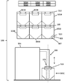
도 9는 본 개시의 용기(501A, 501B, 501C)를 포함하는 적층 가공 시스템(589)을 예시한다. 용기(501A, 501B, 501C)는 사용 시나리오에서의 상이한 시점 동안의, 상이한 상태에 있는 동일한 용기를 나타낸다. 도면의 상부에, 수평 및 수직으로 적층된, 실질적으로 비어 있는 용기(501A)의 배치가 예시된다. 용기(501A)는 충전 스테이션 및/또는 분말 제조자로의 수송 동안 찌부러진다. 중앙에, 수평 및 수직으로 적층된, 충전된 용기(501B)의 배치가, 예를 들어 적층 가공 장치(591)로의 충전 상태 수송(filled transport) 또는 그것과의 상호연결 전의 보관에 대해 예시된다. 하부에, 적층 가공 장치(591) 및 상호연결된 용기(501C)가 예시된다. 도 9의 시스템(589)의 예시된 구성요소는 이전의 도면 및 이후의 도면에 관하여 논의되는 용기 및 구성요소 중 임의의 것에 대응할 수 있다.FIG. 9 illustrates a
각각의 찌부러진 용기(501A)는 비어 있는, 적어도 부분적으로 가요성인 저장소를 포함할 수 있다. 용기(501A)는 찌부러진 저장소에 부착된 절첩식 보강 구조체를 포함할 수 있다. 이를 위해, 보강 구조체는 절첩선을 포함할 수 있다. 저장소는 보강 구조체에, 둘 모두의 구조체가 서로 부착된 채로 유지되는 동안, (i) 찌부러짐/절첩, 및 (ii) 확장/절첩 해제를 허용하도록 선택적으로 부착될 수 있다. 다른 예에서, 저장소와 보강 구조체는 별개의 행위에 의해, 각각, 찌부러짐 후에 및 전에 부착 및 분리될 수 있다. 적층된 그리고 찌부러진 용기(501A)는 패키지 제조자로부터 축조 재료 충전 시설로 수송될 수 있거나, 찌부러진 용기(501A)는 고갈 후에, 사용자에 의해, 재충전 스테이션으로 복귀될 수 있다.Each crushed
하나의 예에서, 찌부러진 용기(501A)는 충전 또는 수송 공정의 하류에 부착되는 별개의 찌부러진 부분, 이를테면 예를 들어 별개의 찌부러진 저장소 및 보강 구조체, 또는 각각의 부분을 포함한다. 하나의 예에서, 전술한 도면 중 일부에 관하여 설명된 바와 같은, 출구 구조체 또는 스루풋 구조체와 같은 소정의 강성 구성요소는 개별적으로 수송되도록 연결(분리)가능하다.In one example, the crushed
도 9의 중앙에 있는, 충전된 용기(501B)의 적층된 세트 중의 용기(501B)는 각각 축조 재료로 충전된 저장소(503)를 포함한다. 각각의 저장소(503)는 깔때기형 하단부 부분(507), 및 충전된 저장소(503)를 보강하는 보강 구조체(523)를 가질 수 있다. 보강 구조체(523)는 용기(501B)의 나머지를 위한 지지체로서 기능할 수 있다. 각각의 용기(501B)는 출구 구조체(513)를 포함한다. 하나의 예에서, 출구 구조체(513)는 용기(501B)가 사용을 위해 개방될 때까지 밀봉된다(도면의 하부 참조). 다른 예에서, 용기(501B)는 상단부 측에 제거가능한 또는 개방가능한 커버(593)를 포함한다. 하나의 예에서, 커버(593)는 용기(501B)의 밀봉, 보호 및 적층을 돕는다. 용기(501B)는 수송 준비는 물론 사용 준비가 된다. 용기(501B)는 손쉽게 적층 가공 장치(591)에 연결되고 사용 후에 교체될 수 있다. 모든 용기(501B)는 적층 가공 장치(591)의 관 스나우트(573)에 상호연결하기 위해 유사한 특징부, 또는 적어도 유사한 출구 구조체(513)를 가질 수 있다.The
적층 가공 장치(591)는 진공 관 스나우트(573)를 통해 용기(501)로부터 축조 재료를 흡입하기 위해 압력 유닛(559)을 포함한다. 압력 유닛(559)은 진공 펌프를 포함한다. 압력 유닛(559) 및 용기(501)는 출구 구조체(513)와 스나우트(573)의 상호연결을 용이하게 하기 위해, 그리고 진공 흡입 전에, 그 동안에 그리고 그 후에 분말 누출을 억제하기 위해 상호연결 어댑터를 포함할 수 있다. 적층 가공 장치(591)는 적어도 하나의 축조 재료 재순환 시스템을 추가로 포함할 수 있다.The
소정의 예에서, 적층 가공 장치(591)는 재순환 시스템에 더하여, 융제(fusing agent) 분배기, 예를 들어 프린트헤드를 포함한다. 적층 가공 장치(591)는 예를 들어 축조 재료의 버퍼링(buffering) 또는 재순환을 위해서, 용기(501)를 (재)충전하기 위한 축조 재료 반환 시스템을 추가로 포함할 수 있다. 이를 위해, 압력 유닛(459)은 저장소(503)로부터의 축조 재료 회수 및 저장소의 축조 재료 충전 둘 모두를 용이하게 하기 위해 양방향 공기 펌프를 포함할 수 있다.In some instances, the
예시된 적층 가공 시스템(589)은 비교적 저가이고, 깨끗하고, 교체가능하고, 폐기가능한 용기(501A, 501B, 501C)를 제공할 수 있다. 용기(501A, 501B, 501C)는 수송, 호스트 장치 상호연결, 축조 재료 수집, 평평한 적층가능 구조로의 찌부러짐, 용이한 폐기, 단일 충전 사용, 다수 충전 사용, 재순환, 보관, 작업자에 의한 들어올림 등을 비롯한 다수의 목적에 적합하다. 용기는 시스템(589)으로부터의 축조 재료(예를 들어, 분말) 누출을 억제하면서 호스트 장치와의 비교적 용이한 상호연결을 촉진한다. 하나의 예에서, 용기는 용기 라이프 사이클 동안, 즉 충전 상태 수송, 장치 상호연결, 회수 동안, 고갈 때까지, 축조 재료 분말 가루가 환경으로 빠져나가는 것을 억제한다. 예를 들어 평균의 힘 및 능력을 가진 임의의 작업자가 한정된 양의 교육으로, 그리고 너무 많은 분말 가루에 노출될 위험이 비교적 낮은 상태로, 한정된 기간 내에, 다수의 용기를 교체할 수 있다. 또한, 찌부러질 수 있는 용기는 용이한 폐기 또는 반환을 허용한다. 하나의 예에서, 주된 용기 재료 중 하나로서 판지를 사용하는 것은 용기를 생분해성으로 만드는 것을 돕는다.The illustrated
도 10은 저장소(603)를 포함하는 용기(601)의 예를 예시한다. 이 예에서, 저장소(603)는 가요성 백이다. 저장소(603)는 확장되었지만 실질적으로 응력이 없는 상태로 예시된다. 저장소(603)는 상단부 벽(615)과 하부 깔때기형 부분(607) 사이에서 연장되는 비-수렴 벽(619A, 619B, 619C, 619D)의 상부 부분(605)을 포함한다. 상부 부분(605)은 대체로 정육면체 형상일 수 있다. 저장소(603)는 하단부 선(609)으로 수렴하는 삼각형 형상의 수렴 벽(621A, 621B, 621C, 621D)의 하부 깔때기형 부분(607)을 추가로 포함한다. 하부 깔때기형 부분(607)은 실질적으로 피라미드 형상인데, 그것의 벽(621A, 621B, 621C, 621D)이 선으로 수렴하는 약간의 차이를 갖는다. 모든 벽(615, 619A, 619B, 619C, 619D, 621A, 621B, 621C, 621D)은 단일의, 일체형, 가요성 플라스틱 백 구조를 갖는다.10 illustrates an example of a
깔때기형 부분(607)은 하단부(609)로부터 상단부 벽(615)까지 측정될 때, 저장소 백의 총 높이(h)의 대략 3% 내지 40%, 또는 대략 3% 내지 25%에 걸쳐 연장될 수 있다. 예시에서, 저장소(603)의 내부 체적은 대략 10 내지 60 리터, 또는 15 내지 50 리터이지만, 유사한 구조가 더 작은 또는 더 큰 내부 체적에 적합할 수 있다.The
용기(601)는 상단부 벽(615) 상에 제공된 출구 구조체(613) 및 스루풋 구조체(635)를 추가로 포함한다. 출구 구조체(613)는 용기(601)로부터 축조 재료를 회수하기 위해 외부 수집 시스템의 압력 유닛에 연결하도록 의도된다. 스루풋 구조체(635)는 제 1 모드에서 용기(601) 내로 공기를 통기시키도록 의도되며, 제 2 모드에서 용기(601) 밖으로 축조 재료를 수동으로 붓도록 분리될 수 있다. 또한 출구 구조체(613)가 분리가능하다.The
용기(601)는 상단부 벽(615) 내에 제 1 개구(697A) 및 제 2 개구(697B)를 포함한다. 제 1 및 제 2 개구(697A, 697B)는 나란히 연장된다. 비교적 강성의 개구 커넥터(695A, 695B)가, 각각, 각각의 개구(697A, 697B) 주위에서 상단부 벽(615)에 부착된다. 각각의 강성의 개구 커넥터(695A, 695B)는, 각각, 출구 구조체(613)와 스루풋 구조체(635)를 연결하기 위한 스크류 나사산 형성된 원통형 목부 부분, 및 스크류 나사산 형성된 목부 부분 주위의 플랜지 부분을 포함하며, 여기서 플랜지 부분은 목부 부분의 중심축에 실질적으로 직교하여, 부분적으로 상단부 벽(615)에 평행하게 연장될 수 있다. 플랜지 부분은 누출을 방지하기 위해 상단부 벽(615)에 부착되거나 적층될 수 있다. 예에서, 적어도 저장소(603)의 예시된 확장된 상태에서, 제 1 개구(697A) 및 각자의 개구 커넥터(695A)는 상단부 벽(615)의 중심에서 또는 그 부근에서 연장되고, 제 2 개구(697B) 및 각자의 개구 커넥터(695B)는 상기 제 1 개구(697A)와 측벽 사이에서, 상단부 벽(615)의 중심으로부터 떨어져 연장된다. 제 1 및 제 2 개구 커넥터(697A, 697B)는 출구 구조체(613)와 스루풋 구조체(635)의 손쉬운 부착 또는 분리를 촉진한다. 출구 구조체(613)와 스루풋 구조체(635)가 분리되고, 저장소(603)가 비어 있을 때, 저장소(603)의 나머지는 손쉽게 찌부러질 수 있다.The
예시된 예에서, 출구 구조체(613)는 제 1 개구 커넥터(695A)에 스크류 끼워맞춤된다. 또한, 출구 구조체(613)는 개폐 가능한 리드(613A), 어댑터(651), 어댑터(651)를 통한 출구 개구(631), 및 출구 개구(631)로부터 깔때기형 저장소 부분(607) 내로 연장되는 종방향 출구 관(633)을 포함한다. 어댑터(651)는 적층 가공 시스템의 스나우트와의 비교적 용이하고 확실한 상호연결을 촉진할 수 있다. 어댑터(651)는 어댑터(651)의 환형 인터페이스 면(663)의 외측 에지(661)를 따른 적어도 하나의 직립 원주방향 벽(657)을 포함한다. 인터페이스 면(663)은 축조 재료/공기 유동 방향(A)에 직교하여, 출구 개구(631)와 직립 벽(657) 사이에서, 출구 개구(631) 주위에 연장된다. 적어도 하나의 자기적 안내 특징부(655), 데이터 인터페이스(667), 및 돌출형 센서 트리거 구조체를 포함한 몇몇의 인터페이스 요소가 원주방향 벽(657) 내에 인터페이스 면(663)에 제공된다.In the illustrated example, the
하나의 예에서, 관(633)의 단부 부분(637)은, 예를 들어 핀(fin)(640) 사이에, 측방향 축조 재료 입구(639)를 포함한다. 예에서, 적어도 4개의 핀과 4개의 입구 개구가 단부 부분(637) 주위에 균일하게 분포된다. 핀(640)은 가요성 저장소 재료가 입구(639)를 차단하는 것을 방지하기 위해 관(633)의 직경으로부터 측방향으로 돌출할 수 있으며, 또한 난류 특징부를 제공할 수 있다. 단부 부분(637)은 캡(641)을 추가로 포함할 수 있다. 캡(641)이 또한 저장소(603)의 가요성 하단부 벽이 개구(639)를 차단하는 것을 방지하면서 축조 재료가 관(633)에 들어가도록 허용할 수 있다. 예에서, 캡(641)은 저장소 하단부(609)에 접촉하여, 출구 구조체(613) 전체가 저장소(603)의 추가의 구조적 보강을 제공한다. 어댑터(651), 관(633), 및 단부 부분(637)은 서로 끼워맞춤될 수 있고, 손쉽게 연결가능하고 분리가능할 수 있다.In one example, the
스루풋 구조체(635)는 제 2 개구 커넥터(695B)에 연결되는데, 예를 들어 스크류 끼워맞춤된다. 스루풋 구조체(635)는 필터 홀더(647) 및 필터(645)를 포함할 수 있다. 필터(645)는 축조 재료를 보유하면서 공기가 통과하도록 허용하기 위해 제 2 개구(697B)를 덮는다. 스루풋 구조체(635)는 축조 재료가 제 2 개구(697B)를 통과하도록 허용하기 위해 분리될 수 있는데, 예를 들어 스크류 해제될 수 있다. 제 2 개구(697B)는 저장소(603) 밖으로 축조 재료를 수동을 붓는 것을 용이하게 하기 위해 제 1 개구(697A)보다 측벽에 더 가까이 연장될 수 있다. 출구 구조체(613)는 그러한 붓기 동안 리드(613A)에 의해 폐쇄될 수 있다. 따라서, 용기(601)는 출구 개구(631)를 통한 자동 진공 축조 재료 회수와, 제 2 개구(697B)를 통한 축조 재료의 수동 붓기 둘 모두를 용이하게 한다.The
예시된 용기(601)는, 예를 들어 PE로 제조된, 가요성 저장소일 수 있다. 충전된 그리고 밀봉된 상태에서, 너무 많은 주위 공기 및/또는 증기가 분말과 접촉하는 것을 억제하기 위해, 밀봉 필름이 출구 구조체(613)를, 예를 들어 인터페이스 면(663) 위 및 리드(613A) 아래에서, 그리고 스루풋 구조체(631)를, 예를 들어 필터 위에서 밀봉할 수 있다. 밀봉 필름은 사용 전에 제거될 수 있다.The illustrated
추가의 예에서, 보강 구조체가 저장소(603)를 지지하기 위해 저장소(603)에 부착될 수 있다. 예에서, 보강 구조체는 저장소(603)의 벽(619A, 619B, 619C, 619D, 621A, 621B, 621C, 621D) 모두에 인접하게 연장된다. 보강 구조체는 저장소(603)의 상부 부분(605)의 2개의 서로 반대편에 있는 측벽(619A, 619B)에 부착되는 동시에, 2개의 다른 서로 반대편에 있는 측벽(619C, 619D)이 보강 구조체에 관하여 휘어지도록 허용할 수 있다. 또한, 하단부 부분(607)의 2개의 서로 반대편에 있는 측벽(621A, 621B)이 보강 구조체에 부착될 수 있는 반면, 2개의 다른 하단부 벽(621C, 621D)은 휘어지도록 허용된다. 예를 들어, 부착된 측벽(619A, 619B, 621A, 621B)은 그것의 표면적의 대부분을 따라 보강 구조체에 부착될 수 있다. 예를 들어, 휘어지는 측벽(619C, 619D, 621C, 621D)은 전혀 부착되지 않거나, 점 또는 작은 표면적에서만 부착된다. 실제로, 예시된 예에서, 휘어지는 벽(619C, 619D, 621C, 621D)에는, 예를 들어 하단부(609)에 있는 수집 영역을 향한 난류 또는 분말 유동을 향상시키는 방식으로, 휘어지는 벽(619C, 619D, 621C, 621D)의 소정 부분이 고정된 채로 유지되고 다른 부분이 휘어질 수 있게 하도록 보강 구조체(623)에 연결하기 위한 리벳(622)이 제공된다. 예시된 예에서, 가요성 상단부 벽(615)은 별개의 지지 구조체(623B)에 의해 지지된다. 지지 구조체(623B)는 평탄하다. 지지 구조체는 개구 커넥터(695A, 695B) 및 이에 의해 상단부 벽(615)을 지지한다. 예를 들어, 지지 구조체(623B)는 본질적으로 보강 구조체에 의해 또는 그것의 일부에 의해 지지될 수 있다.In a further example, a reinforcing structure may be attached to the
도 11은 외부 수집 시스템과 함께 본 개시의 축조 재료 용기를 사용하는 방법의 예를 예시한다. 수집 시스템은 축조 재료 재순환 유닛 및/또는 3D 프린터와 같은 적층 가공 장치의 부분일 수 있다. 방법은, 예를 들어 미사용 축조 재료로 충전된, 새로운 용기를 제공하는 것을 포함한다(블록 100). 방법은 용기를 수집 시스템 부근에 배치하는 것을 포함한다(블록 110). 수집 시스템은 압력 유닛을 포함할 수 있다. 방법은 수집 시스템을 용기의 축조 재료 출구 구조체와 상호연결하는 것을 포함한다(블록 120). 방법은, 예를 들어 용기가 실질적으로 빌 때까지, 용기로부터 축조 재료를 회수하는 것을 포함한다(블록 130). 방법은 용기를 폐기물로서 폐기하거나, 빈 용기를 재활용 또는 재충전을 위해 수송하는 것을 포함한다(블록 140). 방법은 다른 충전된 용기를 수집 시스템과 상호연결하는 것을 포함한다(블록 150). 축조 재료는 고갈 때까지 다른 용기로부터 회수될 수 있고, 또한 다른 용기는 폐기, 재활용 또는 재충전될 수 있다(블록 130, 블록 140). 블록 130 내지 블록 150의 사이클은 적층 가공 장치의 수명 동안 여러 번 반복될 수 있다. 본 개시의 용기는 초기 충전, 수송, 보관, 및 적층 가공 장치로의 축조 재료 전달을 포함할 수 있는 이러한 다수의 단계 동안 축조 재료를 봉입할 수 있다. 본 개시의 예시적인 용기 중 일부는 수송 또는 보관을 위한 빈 용기의 부분의 찌부러짐을 용이하게 할 수 있다.Figure 11 illustrates an example of a method of using the present build container of the present disclosure with an external collection system. The collection system may be part of a stack processing apparatus such as a building material recycle unit and / or a 3D printer. The method includes, for example, providing a new container filled with unused construction material (block 100). The method includes placing the vessel near the collection system (block 110). The collection system may include a pressure unit. The method includes interconnecting the collection system with the building material outlet structure of the vessel (block 120). The method includes recovering the building material from the vessel, for example, until the vessel is substantially empty (block 130). The method includes discarding the container as waste, or transporting the empty container for recycling or refilling (block 140). The method includes interconnecting other filled containers with the collection system (block 150). The building material can be recovered from the other vessel until depleted, and the other vessel can also be disposed of, recycled or refilled (block 130, block 140). The cycle from
도 12는 본 개시의 축조 재료 용기를 버퍼로서 사용하는 방법의 예를 예시한다. 방법은 축조 재료로 충전된 새로운 용기를 제공하는 것을 포함할 수 있다(블록 200). 방법은 용기를 적층 가공 장치 부근에 배치하는 것을 포함할 수 있다(블록 210). 적층 가공 장치는 리사이클러 및 수집 시스템을 포함한다. 수집 시스템은 압력 유닛을 포함할 수 있다. 방법은 적층 가공 장치를 용기와 상호연결하는 것을 포함한다(블록 220). 방법은 적층 가공 장치가 출구 개구를 통해 용기로부터 축조 재료를 회수하게 하는 것을 포함한다(블록 230). 예를 들어, 그러한 회수 동안, 공기가 제 2 개구를 통해 용기 내로 통기될 수 있다. 방법은, 예를 들어 적층 가공이 축조 재료를 혼합하거나, 재순환시키거나, 프린팅하고 있는 동안, 적층 가공 장치가 제 2 개구를 통해 용기를 재충전하게 하는 것을 추가로 포함할 수 있다(블록 240).Figure 12 illustrates an example of a method of using the build-up material container of the present disclosure as a buffer. The method may include providing a new container filled with a build material (block 200). The method may include placing the vessel in proximity to the stack processing apparatus (block 210). The stack processing apparatus includes a recycler and a collection system. The collection system may include a pressure unit. The method includes interconnecting the stack processing apparatus with the container (block 220). The method includes causing the stack processing apparatus to retrieve the build material from the vessel through the exit opening (block 230). For example, during such withdrawal, air can be vented through the second opening into the vessel. The method may further include, for example, allowing the lamination apparatus to refill the vessel through the second opening while the lamination process is mixing, recirculating, or printing the building material (block 240).
도 13은 본 개시의 축조 재료 용기를 사용하는 방법의 예를 예시한다. 본 방법의 용기는 예시적인 용기 중 임의의 것일 수 있거나, 이전의 도 3, 도 4 내지 도 12 중 임의의 것에 관하여 설명된 바와 같은 구성요소 중 임의의 것을 포함할 수 있다. 방법은 축조 재료로 충전된 새로운 용기를 제공하는 것을 포함할 수 있다(블록 300). 용기는 수집 시스템의 대응하는 어댑터에 연결하기 위한 어댑터를 갖는 출구 구조체, 및 통기를 위한 필터를 갖는 스루풋 구조체를 포함한다. 방법은 필터를 분리하고 출구 구조체를 폐쇄하는 것을 포함한다(블록 310). 예를 들어, 필터를 분리하는 것은 스루풋 구조체를 개방시켜 축조 재료가 통과해 유동하도록 허용한다. 출구 구조체는 리드에 의해 폐쇄될 수 있다. 방법은 제 2 개구를 통해 축조 재료를 수동으로 붓는 것을 추가로 포함한다(블록 320).Figure 13 illustrates an example of a method of using a build-up material container of the present disclosure. The container of the present method may be any of the exemplary containers or may comprise any of the components as described above with respect to any of the previous Figures 3, 4 to 12. The method may include providing a new container filled with a build material (block 300). The vessel includes an outlet structure having an adapter for connection to a corresponding adapter of the collection system, and a throughput structure having a filter for venting. The method includes disconnecting the filter and closing the exit structure (block 310). For example, separating the filter opens the throughput structure allowing the build material to flow through. The exit structure may be closed by a lid. The method further includes manually pouring the building material through the second opening (block 320).
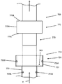
도 14는 도 6 내지 도 8과 유사한, 출구 구조체(713)에 연결되도록 의도되는 수집 시스템의 예시적인 진공 스나우트(773)의 도식을 예시한다. 스나우트(773)는 제 2 어댑터(775)로부터 연장된다. 제 2 어댑터(775)는 외측 벽(775A), 예를 들어 원통형 외측 벽(775A), 및 제 2 인터페이스 면(475C) 반대편의 상단부 리지(475B)를 가질 수 있다. 제 2 인터페이스 면(475C)은 출구 구조체의 인터페이스 면(763)에 연결하도록 의도된다. 스나우트(773) 및 제 2 어댑터(775)는 수집 시스템의 부분인 압력 유닛(459)의 부분이다. 스나우트(773)는 출구 구조체(713) 내에 삽입하기 위한 관 형상의 노즐이다.Figure 14 illustrates a schematic of an exemplary vacuum scan 773 of a collection system intended to be coupled to the
출구 구조체(713)는 그것의 중심에서 출구 개구(731)를 갖는 제 1 어댑터(751)를 포함한다. 출구 구조체는 적어도 하나의 직립 원주방향 벽(457)을 가질 수 있다. 출구 관(733)이 제 1 어댑터(751)로부터 하향으로 연장된다. 개구(731)는 출구 관(733)에 대한 접근을 제공한다. 스나우트(773)는 축조 재료 및 공기를 흡입하기 위해 출구 관(733) 내에 삽입되도록 의도된다. 스나우트(773)는 출구 관(733)의 원주방향 내측 벽에 비교적 단단히 또는 비교적 느슨하게 끼워맞춤될 수 있다.The
하나의 예에서, 적어도 하나의 보유 특징부(755A)가, 삽입될 때 스나우트(773)와 맞물려 그것을 보유하기 위해, 출구 관(733)의 내측 벽으로부터 돌출한다. 예시된 예에서, 보유 특징부(755A)는, 내측 벽으로부터 돌출하고, 스나우트(773)가 관(733) 내로 밀어 넣어질 때 변형되는 변형가능한 구조체를 포함할 수 있다. 보유 특징부(755A)는 관과 일체일 수 있다. 예를 들어, 보유 특징부(755A)는 출구 관(733)과 동일한 플라스틱 화합물의 것이다. 보유 특징부(755A)는 유동 방향(F)에 직교하여, 출구 관(733)의 내측 벽으로부터 돌출하는 환형 리지일 수 있다. 다른 예에서, 적어도 하나의 범프(bump) 또는 리브(rib), 또는 일련의 범프 또는 리브가 제공될 수 있다. 상이한 예에서, 리브는 유동 방향(F)에 평행하게 또는 직교하여 연장될 수 있다. 보유 특징부(755A)는 스나우트(773)가 삽입될 때 출구 관(733)과 스나우트(773) 사이의 마찰 끼워맞춤을 용이하게 할 수 있다. 보유 특징부(755A)는 또한, 예를 들어 부유하는 축조 재료 가루가 빠져나가는 것을 억제하기 위해, 연결된 상태에서 출구 구조체(713)를 밀봉할 수 있다.In one example, at least one
다른 예에서, 어댑터(751)의 직립 벽(757)은 직립 벽(757)의 내측 표면으로부터 돌출하는, 관(733)의 전술된 보유 특징부(755A)와 유사한, 적어도 하나의 보유 특징부(755B)를 포함한다. 벽 보유 특징부(755B)는, 제 2 어댑터(775)의 외측 벽(775A)과 맞물리고 이에 의해 또한 스나우트를 삽입된 상태로 보유하기 위해, 관(733)의 보유 특징부(755A)에 더하여 또는 그 대신에 제공될 수 있다. 유사하게, 그러한 보유 특징부(755B)는 유동 방향(F)에 직교하여, 원주방향 벽(757)의 내측 표면으로부터 돌출하는 환형 리지일 수 있다. 다른 예에서, 적어도 하나의 범프 또는 리브, 또는 일련의 범프 또는 리브가 제공될 수 있다. 상이한 예에서, 리브는 유동 방향(F)에 평행하게 또는 직교하여 연장될 수 있다.The
도 15에, 출구 구조체(733)의 부분인 보유 특징부(755C)의 다른 예가 예시된다. 이 예에서, 보유 특징부(755C)는 래치를 포함할 수 있다. 예를 들어, 보유 특징부(755C)는 직립 벽(757)의 부분이거나 그것에 연결될 수 있다. 예를 들어, 보유 특징부(755C)는 제 2 어댑터(775) 및 스나우트(773)가 출구 구조체(713)에 연결되도록 허용하기 위해 외향으로, 그리고 어댑터(775)의 상단부 리지(775B)에 래칭하기 위해 내향으로 힌지식 운동을 하도록 의도된다. 보유 특징부(755C)는 어댑터(775)의 상단부 리지(775B)와 맞물리기 위한 후크(755D) 등을 포함할 수 있다. 예를 들어, 후크(755D)는 스나우트(773)를 출구 구조체(713)로부터 해제시키기 위해, 힘에 의해, 수동으로 상단부 리지(775B)로부터 제거될 수 있다.Another example of the retaining
보유 특징부(755C)는 리브 힌지(live hinge)를 중심으로 힌지식 운동을 하는, 직립 벽(757) 또는 어댑터(751)의 일체형 부분일 수 있다. 다른 예에서, 보유 특징부(775C)는, 예를 들어 금속 핀을 중심으로 힌지식 운동을 하는, 별개의 힌지형 부분일 수 있다. 하나의 예에서, 적어도 3개의 힌지형 보유 특징부(755C)가 상단부 리지(775B)에 걸기 위해 어댑터(751) 주위에 균일하게 분포되어 제공된다. 예에서, 보유 특징부(755C)는 인터페이스 면(763)에 부착된다. 다른 예에서, 보유 특징부(755C)는 직립 벽(757)에 부착되거나, 직립 벽(757)(의 일부)을 형성할 수 있다. 보유 특징부(755C)의 치수는 제 2 어댑터 벽(775A)의 높이에 맞춰질 수 있다.
도 14 및 도 15의 예시적인 보유 특징부(755A, 755B, 755C)는, 예를 들어 자기적 안내 특징부(455) 대신에 또는 그것에 더하여, 도 6 내지 도 8의 출구 구조체(413)에 적용될 수 있다.The exemplary retaining features 755A, 755B and 755C of Figures 14 and 15 may be applied to the
본 개시의 용기의 저장소 부분은 그것의 높이의 대부분에 걸쳐 대체로 정육면체 형상을, 그리고 하단부 부근에서 뒤집힌 피라미드 형상을 가질 수 있다. 정육면체 부분은 실질적으로 비-수렴, 예를 들어 대략 직립한 벽을 갖는다. 정육면체 및 피라미드 형상은 직사각형 단면을 가지며, 이는 예를 들어 원통 또는 원추형 형상과 같은 둥근 단면과 비교해 효율적인 보관 및 수송을 용이하게 할 수 있다.The reservoir portion of the container of the present disclosure may have a generally cuboidal shape over most of its height and an inverted pyramidal shape in the vicinity of its lower end. The cube portion has a substantially non-converging, e.g., substantially upright, wall. The cube and pyramid shapes have a rectangular cross-section, which can facilitate efficient storage and transport compared to a round cross-section, such as, for example, a cylindrical or conical shape.
비-수렴 상부 부분과 수렴 하부 부분은 일체형의 가요성 백-유사 저장소의 부분일 수 있다. 수렴 하단부는 축조 재료의 대부분이 중력에 의해 하단부에 있는 수집 영역을 향해 낙하하도록 허용한다. 비-수렴 상부 부분은 비교적 큰 체적의 축조 재료를 용기의 윤곽 내에 저장하는 것을 용이하게 한다.The non-converging upper portion and the converging lower portion may be part of an integral flexible bag-like storage. The converging bottom allows most of the building material to fall towards the collection area at the bottom by gravity. The non-converging upper portion facilitates storing a relatively large volume of the building material within the contour of the vessel.
하나의 예에서, 저장소는 적어도 부분적으로 가요성이다. 저장소의 가요성 벽의 부분은 양압 또는 음압이 가해질 때 휘어지고/휘어지거나 진동할 수 있으며, 이에 의해 축조 재료의 부분이 저장소 내에 뒤에 남아 있는 것을 방지하고 축조 재료의 유동을 도울 수 있다. 소정 시나리오에서, 축조 재료의 일부는 벽의 진동 또는 휘어짐에 의해 가요성 벽 내에 형성된 소정의 포켓 또는 모서리로부터 그 자신을 해제시킬 수 있다. 이에 의해, 축조 재료의 대부분 또는 전부가 저장소로부터 회수될 수 있다.In one example, the repository is at least partially flexible. The portion of the flexible wall of the reservoir can be bent and / or bent or vibrated when a positive or negative pressure is applied, thereby preventing a portion of the build material from remaining behind in the reservoir and helping flow of the build material. In some scenarios, a portion of the building material may release itself from a predetermined pocket or edge formed in the flexible wall by vibration or warping of the wall. Thereby, most or all of the building material can be recovered from the storage.
소정 예에서, 저장소의 하부 부분은 깔때기형 형상을 가질 필요가 없다. 예를 들어, 저장소의 측벽은 상단부로부터 하단부까지 직립일 수 있다. 예를 들어, 측벽은 실질적으로 직사각형일 수 있다. 그러한 용기는 축조 재료를 용기의 윤곽 내에 효율적으로 저장할 수 있다. 불리한 점은, 깔때기형 저장소와 비교해, 그것은 하단부로부터 축조 재료의 전부 또는 대부분을 뽑아내기가 더 어려울 수 있다는 것일 수 있다. 그러한 용기에서, 그러한 잠재적인 불리한 점을 상쇄하기 위해 소정의 조치가 제공될 수 있는데, 예를 들어 저장소 내부에서 하단부까지 연장되는 출구 관이, 저장소의 하단부의 하단부 에지 부근의 축조 재료에 도달할 수 있도록, 단부에서 만곡되거나 가요성으로 만들어지거나, 또는 다른 방식으로 맞추어질 수 있다. 다른 예에서, 하단부는, 예를 들어 도 3에 예시된 바와 같이, 축조 재료가 중심 하단부 수집 영역을 향해 낙하하거나 이동하는 방식으로, 진공 압력하에서 진동하거나 휘어지도록 가요성으로 만들어질 수 있다. 다시 도 3을 참조하면, 종방향 출구 관(117)이 중심에서 하단부와 맞물릴 수 있으며, 이에 의해 중심 주위의 하단부가 진공 압력하에서 들어올려질 수 있고 출구 관(117)은 중심 하단부에 보유되며, 이에 의해 축조 재료가 출구 관의 흡입 개구의 입구를 향해 이동할 수 있다.In certain instances, the lower portion of the reservoir need not have a funnel-shaped configuration. For example, the side walls of the reservoir may be upright from the top to the bottom. For example, the side wall may be substantially rectangular. Such a container can efficiently store the build material in the contour of the container. The disadvantage is that, compared to a funnel-type reservoir, it may be more difficult to extract all or most of the building material from the bottom end. In such a vessel, certain measures may be provided to offset such potential disadvantages, for example an outlet tube extending from the interior to the lower end of the reservoir may reach the building material near the lower edge of the lower end of the reservoir , Bent or flexed at the ends, or otherwise fitted. In another example, the lower end can be made flexible to vibrate or bend under vacuum pressure, for example, in such a manner that the build material falls or moves toward the central lower end collection area, as illustrated in Fig. Referring again to FIG. 3, the
하나의 예에서, 용기는 수송, 적층 가공 장치 상호연결, 축조 재료 회수, 교체, 및 폐기에 적합하다. 하나의 예에서, 폐기 목적으로, 보강 구조체는 판지 또는 다른 생분해성 재료를 포함한다. 다른 생분해성 재료는 다른 셀룰로오스 섬유 기반 재료, 전분 등을 포함할 수 있다. 가요성 저장소는 소정의 폴리에틸렌 필름과 같은 비교적 분해성인 플라스틱으로 제조될 수 있다. 다른 예에서, 가요성 저장소는 코팅된 압축 셀룰로오스 기반 재료와 같은 적어도 하나의 생분해성 층을 포함할 수 있다. 특수 코팅이 공기/증기 장벽을 제공할 수 있다.In one example, the vessel is suitable for transportation, stacking machine interconnect, building material recovery, replacement, and disposal. In one example, for disposal purposes, the reinforcing structure comprises a cardboard or other biodegradable material. Other biodegradable materials may include other cellulosic fiber based materials, starches, and the like. The flexible storage may be made of relatively degradable plastic, such as certain polyethylene films. In another example, the flexible reservoir may comprise at least one biodegradable layer, such as a coated pressed cellulose-based material. Special coatings can provide air / vapor barrier.
하나의 예에서, 저장소는, 예를 들어 다양한 재료 및/또는 벽 두께를 가짐으로써, 부분적으로 가요성이고 부분적으로 보강될 수 있다. 그러한 예에서, 보강 구조체는, 저장소와는 별개이고 그것에 부착되기보다는, 저장소에 일체일 수 있다. 저장소는 가요성 벽 부분 및 강성 벽 부분을 가질 수 있다. 예를 들어, 저장소는, 일체적으로, (i) 가요성 저장소 벽 또는 저장소 벽의 가요성 부분, 및 (ii) 보강된 저장소 벽 또는 저장소 벽의 부분을 포함한다. 그러한 저장소는 보강된 벽 부분의 절첩을 용이하게 하기 위해 보강된 벽 부분을 따른 절첩선을 가질 수 있다.In one example, the reservoir can be partially flexible and partially reinforced, for example by having various materials and / or wall thicknesses. In such an instance, the reinforcing structure may be integral to the reservoir, rather than being separate from and attached to the reservoir. The reservoir may have a flexible wall portion and a rigid wall portion. For example, the reservoir may integrally comprise (i) a flexible reservoir wall or a flexible portion of the reservoir wall, and (ii) a portion of the reinforced reservoir wall or reservoir wall. Such a reservoir may have a fold line along the reinforced wall portion to facilitate folding of the reinforced wall portion.
하나의 예에서, 본 개시의 용기는 별개의 부분의 조립체일 수 있다. 이를 위해, 별개의 부분의 키트(kit)가 본 개시의 용기를 형성하도록 제공될 수 있다. 키트는 저장소, 보강 구조체, 출구 구조체, 및 스루풋 구조체를 포함할 수 있다. 저장소는 출구 구조체와 스루풋 구조체를 연결하기 위해 사전절단된 개구를 가질 수 있다. 출구 구조체의 별개의 하위-구성요소는 어댑터, 디지털 메모리 회로, 자기적 용소, 종방향 관, 및 측방향 구멍을 갖는 관 단부 부분을 포함할 수 있다. 또한, 스크류 및 접착제가 사용될 수 있다. 또한, 용기의 그래픽 디자인을 가지고 있는 추가의 외측 구조체가 제공될 수 있다. 별개의 밀봉 필름이 용기의 사용을 위해 개방될 때까지 출구 구조체 및 스루풋 구조체를 덮을 수 있다.In one example, the container of the present disclosure may be an assembly of discrete portions. To this end, a separate kit of parts may be provided to form the container of the present disclosure. The kit may include a reservoir, a stiffening structure, an exit structure, and a throughput structure. The reservoir may have pre-cut openings to connect the outlet structure and the throughput structure. The separate sub-components of the exit structure may include an adapter, a digital memory circuit, a magnetron, a longitudinal tube, and a tube end portion with a lateral aperture. Also, screws and adhesives can be used. In addition, an additional outer structure having a graphic design of the container can be provided. The exit structure and the throughput structure can be covered until a separate sealing film is opened for use of the container.
하나의 예에서, 본 개시의 용기에 연결되도록 의도되는, 적층 가공 장치의 압력 유닛은 적어도 10 리터/초 또는 적어도 15 리터/초, 예를 들어 20 내지 30 리터/초의 공기 속도를 갖는다. 그러한 압력 유닛은 대략 5 내지 60 리터의 저장소 체적을 갖는 용기에 연결할 수 있다. 하나의 예에서, 가요성 저장소 벽은 공기가 스루풋 개구를 통해 용기 내로 그리고 출구 개구를 통해 용기 밖으로 순환할 때 휘어지거나 진동하도록 의도된다. In one example, the pressure unit of the stack processing apparatus, intended to be connected to the container of the present disclosure, has an air velocity of at least 10 liters / second or at least 15 liters / second, for example 20 to 30 liters / second. Such a pressure unit may be connected to a vessel having a storage volume of approximately 5 to 60 liters. In one example, the flexible reservoir wall is intended to bend or vibrate as air circulates through the throughput opening into and out of the vessel through the outlet opening.
본 개시의 용기는 적층 가공을 위한 적층 가공 장치에 축조 재료를 제공하도록 배열될 수 있다. 소정의 예에서, 적층 가공 장치는 용기로부터 분말을 수집하고 그것을 적층 가공 공정에 추가하기 위해 용기에 직접 연결가능하다. 적층 가공 장치는 압력 유닛을 포함하는 리사이클러 및/또는 3D 프린터일 수 있다. 다른 예에서, 별개의 특수화된 축조 재료 압력 유닛이 용기로부터 적층 가공 장치로 축조 재료를 수송하는 데 사용될 수 있다.The vessel of the present disclosure may be arranged to provide a building material to a stack processing apparatus for stack processing. In some instances, a stack processing apparatus is directly connectable to the vessel to collect the powder from the vessel and add it to the lamination process. The stack processing apparatus may be a recycler and / or a 3D printer including a pressure unit. In another example, a separate specialized building material pressure unit may be used to transport the build material from the vessel to the stack processing apparatus.
하나의 예에서, 용기는 대략 5 내지 60 리터, 예를 들어 대략 10 내지 50 리터 또는 대략 15 내지 40 리터의 축조 재료를 저장하도록 의도된다. 축조 재료의 유형에 의존하는 이들 체적 및 관련 중량은 작업자가 용기를 손쉽게 취급하도록, 예를 들어 수송, 보관 및 적층 가공을 위해 용기를 수동으로 들어올리고, 적층하고, 이동시키도록 허용할 수 있다. 또한, 용기는 축조 재료를 수집하기 위해 용이하고, 신속하고, 비교적 산뜻한 상호연결 행위에 의해 적층 가공 장치에 손쉽게 연결될 수 있다. 용기는 빈 때 새로운 용기로 교체될 수 있으며, 이는 실질적으로 비어 있는 상태에서의 용이한 폐기 또는 찌부러짐을 허용할 수 있다. 공정 단계의 대부분 동안, 빠져나가는 축조 재료 분말이 억제될 수 있다.In one example, the vessel is intended to store approximately 5 to 60 liters, for example approximately 10 to 50 liters, or approximately 15 to 40 liters of the building material. These volumes and associated weights, which depend on the type of build material, can allow the operator to manually lift, stack, and move the containers manually for handling, e.g., transport, storage and lamination operations. In addition, the container can be easily connected to the stack processing apparatus by an easy, quick and relatively clean interconnecting action to collect the build material. The container may be replaced with a new container when empty, which may allow for easy disposal or collapse in a substantially empty state. During most of the processing steps, the escaping building material powder can be suppressed.
하나의 예에서, 용기는 미사용 축조 재료의 소스 공급부이다. 다른 예에서, 용기는 재순환된 또는 부분적으로 재순환된 축조 재료의 소스 공급부이다. 또 다른 예에서, 용기는 적어도 일시적으로 버퍼 공급부로서 사용될 수 있다.In one example, the vessel is a source supply of unused build-up material. In another example, the vessel is a source supply of recycled or partially recycled building material. In another example, the vessel may be used at least temporarily as a buffer supply.
본 개시는 "직립", "하부", "상부", "상단부", "하단부", "측부" 등을 언급한다. 이들 설명적 용어는 본 출원의 가독성을 위해 선택되었다. 그러나, 이들 설명적 용어는 용기를 단일 배향만을 갖는 것으로 제한하지 않아야 한다. 이들 설명적 용어는, 용기가 수집 시스템에 연결되고 중력을 사용하여 축조 재료가 하단부로 유동하거나 낙하하도록 허용하는 상태를 지칭할 수 있다. 그러나, 본 개시에 설명된 것과 유사한 구조체가 임의의 배향을 가질 수 있다. 하나의 예에서, "하단부"는, 예를 들어 축조 재료가 저장소 내부로부터 수집되도록 의도되는 경우, 설치된 상태에서 용기의 중력적으로 아래쪽으로 이해될 수 있으며, 다른 설명적 용어는 그 하단부에 상대적인 것으로 해석될 수 있다. 또한, 용기가 비어 있고 사용 중이 아닐 때, 용기의 적절한 사용 배향은 무엇인지가 손쉽게 추론가능할 수 있다. 용기는 예를 들어 수송, 보관, 절첩된 상태, (부분적으로) 분해된 상태 등 또는 다른 비-사용 상태 동안 다른 배향을 가질 수 있는데, 여기서 용기의 하단부인 쪽은 하단부에서 연장되지 않고, 예를 들어, 용기의 상단부 부분이 실제로 하단부 아래에서 또는 옆에서 연장될 수 있다. 또한, 상이한 이유로 상이한 설치/사용 배향이 있을 수 있다. 동일한 용기에 대해 기준계를 사용할 경우, "하단부" 또는 "하부"는 y-축 상의 더 낮은 지점을 지칭하고, "상부" 또는 "상단부"는 동일한 y-축 상의 더 높은 지점을 지칭하고, "측부"는 x-축 또는 z-축 상의 극단을 지칭하고, "직립"은 y-축이 용기의 중심축인 상태를 지칭할 수 있으며, 여기서 기준계는 임의의 배향을 가질 수 있다.This disclosure refers to "upright", "lower", "upper", "upper", "lower", "side" These descriptive terms have been chosen for the readability of the present application. However, these descriptive terms should not limit the container to having only a single orientation. These descriptive terms may refer to a condition in which a vessel is connected to a collection system and using gravity to allow the build material to flow or fall to the bottom. However, structures similar to those described in this disclosure may have any orientation. In one example, "lower end" can be understood to be gravitationally downward of the vessel in the installed state, for example when the build-up material is intended to be collected from inside the reservoir, and other descriptive terms are relative to the lower end thereof Can be interpreted. Also, when the container is empty and not in use, it can be easily deduced what the proper usage orientation of the container is. The container may have other orientations such as, for example, transport, storage, folded condition, (partially) disassembled condition, or other non-use condition wherein the lower end of the container does not extend from the lower end, For example, the upper end portion of the container may actually extend below or beside the lower end. There may also be different installation / usage orientations for different reasons. Refers to the lower point on the y-axis, "upper" or "upper end" refers to the higher point on the same y-axis, Quot; refers to the extreme on the x-axis or z-axis, and "upright" can refer to the state where the y-axis is the center axis of the vessel, where the reference system can have any orientation.
본 개시의 일 태양은 (i) 축조 재료를 수용하기 위한 저장소(3, 3A, 3B, 103, 103B, 203, 503, 603)를 포함하는 적층 가공 축조 재료 용기(1, 1A, 1B, 101, 101B, 201, 501, 601)를 포함한다. 저장소는, 적어도 충전된 상태에서, (i) 적어도 하나의 비교적 비-수렴 측벽(19, 19A, 19B, 119, 119B, 219, 619A 내지 619D)을 갖는, 저장소의 높이(H)의 절반 초과의 상부 부분(5, 5A, 5B, 105, 105B, 205, 605), 및 (ii) 수렴 측벽(21, 21A, 21B, 121A, 121B, 221, 621)을 갖는, 상부 부분과 하단부(9, 9A, 9B, 109, 109B, 209, 609) 사이의 하부 부분(7, 7A, 7B, 107, 107B, 207, 607)을 포함한다. 용기는 축조 재료가 저장소를 빠져나가도록 허용하기 위해 축조 재료 출구 구조체(13, 13A, 13B, 113, 113B, 213, 313, 413, 513, 613)를 추가로 포함한다. 예를 들어, 상부 부분은 대체로 정육면체 형상이고 하부 부분은 대체로 피라미드 형상이다. 피라미드형 벽(21, 21A, 21B, 121A, 121B, 221, 621)은 절두되거나, 둥근 표면에서 또는 선을 따라 종료될 수 있다.One aspect of the present disclosure relates to a method of manufacturing a stacked build-up material container (1, 1A, 1B, 101, 102) comprising (i) a reservoir (3, 3A, 3B, 103, 103B, 203, 503, 603) 101B, 201, 501, 601). The reservoir is at least partially filled with (i) at least one relatively non-converging sidewall (19, 19A, 19B, 119, 119B, 9A, 9A, 9B, 9A, 9B, 9A, 9A, 9A, 9A, 9A, 9B, 7A, 7B, 107, 107B, 207, 607 between the first, second, third, fourth, fifth, The vessel further includes a build-up material outlet structure (13, 13A, 13B, 113, 113B, 213, 313, 413, 513, 613) to allow the build material to exit the reservoir. For example, the upper portion is generally cube-shaped and the lower portion is generally pyramidal. The
본 개시의 다른 태양은 가요성 재료를 포함하는 상대적으로 가요성인 저장소(3, 3A, 3B, 103, 103B, 203, 503, 603), 상대적으로 가요성인 저장소의 부분을 지지하기 위한, 가요성 재료보다 강성인, 상대적으로 강성인 재료를 포함하는 보강 구조체(123, 123B, 223, 523), 및 개구(231, 431, 631)를 통해 저장소의 내부에 대한 접근을 제공하는 출구 구조체(13, 13A, 13B, 113, 113B, 213, 313, 413, 513, 613)를 포함하는 3D 프린팅 축조 재료 용기(1, 1A, 1B, 101, 101B, 201, 501, 601)를 포함한다. 가요성 벽은 압력 차이에 의해 이동하거나 진동할 수 있다. 가요성 저장소 벽(19, 19A, 19B, 119, 119B, 219, 619A 내지 619D, 21, 21A, 21B, 121A, 121AA, 121B, 221, 621)이 어느 정도 탄성인 예에서, 이들 벽은 대략 1 * 109 N/m2 GPa 이하의 영률을 가질 수 있다. 보강 구조체는, 예를 들어 저장소의 내부에 압력이 인가되는 경우, 저장소의 다른 비-부착된 부분의 휘어짐을 용이하게 하면서 저장소의 소정 부분을 유지할 수 있다. 예를 들어, 보강 구조체를 선택적으로 부착함으로써, 실질적으로 전부의 저장소 벽 표면이 유지될 수 있는 것과 동시에 다른 벽 표면이 완전히 또는 부분적으로 가요성이도록 허용될 수 있다. 하나의 예에서, 보강 구조체는 판지 절첩 구조체를 포함한다. 다른 예에서, 보강 구조체는 와이어프레임과 같은 지지 프레임일 수 있다.Another aspect of the present disclosure relates to a relatively
비어 있는 상태에서, 가요성 저장소는 찌부러질 수 있다. 보강 구조체는 절첩가능할 수 있다. 소정의 예에서, 저장소 구조체는 부분적으로 강성 및 부분적으로 가요성일 수 있다. 저장소는 비교적 낮은 공기/증기 투과성을 갖는 반면, 보강 구조체는 저장소보다 높은 공기/증기 투과성을 갖는다. 예를 들어, 판지는 비교적 높은 공기/증기 투과성을 갖는다.In an empty state, the flexible storage can collapse. The reinforcing structure may be foldable. In certain instances, the storage structure may be partially rigid and partially flexible. The reservoir has relatively low air / vapor permeability, while the reinforced structure has a higher air / vapor permeability than the reservoir. For example, the cardboard has relatively high air / vapor permeability.
출구 구조체는 저장소의 상단부 부분에 출구 개구를 포함할 수 있다. 예를 들어, 출구 개구는 상단부 벽을 통해, 또는 상단부 벽 부근의 측벽 내에 제공될 수 있다. 따라서, 축조 재료는 용기의 상단부 측으로부터 회수될 수 있으며, 이는 사용 동안 용기를 지면 상에 또는 그 부근에 배치하는 것을 허용할 수 있다.The outlet structure may include an outlet opening at an upper end portion of the reservoir. For example, the exit opening may be provided through the top wall, or within the side wall near the top wall. Thus, the building material can be recovered from the top end side of the container, which can allow the container to be placed on or near the ground during use.
출구 구조체는 손쉽게 외부 수집 시스템의 대응하는 제 2 어댑터에 연결하고 그것으로부터 분리하기 위한 제 1 어댑터를 포함할 수 있다. 제 1 어댑터는 공기 또는 축조 재료 유동 방향에 대략 수직인, 출구 개구 주위의 인터페이스 면을 포함하며, 여기서 적어도 하나의 안내 특징부 및 적어도 하나의 추가 인터페이스 특징부가 인터페이스 면에 제공된다. 그러한 안내 특징부의 예는 수집 시스템의 대응하는 자기적 특징부를 끌어당기기 위한 자기적 특징부이며, 여기서 예시적인 인터페이스 특징부는 데이터 인터페이스 및 센서 트리거 구조체를 포함할 수 있다. 안내 특징부의 다른 예는 데이터 인터페이스 슬롯(또는 돌출부)이며, 여기서 인터페이스 특징부는 자기적 특징부 또는 센서 트리거 구조체일 수 있다. 수집 시스템을 위한 추가의 안내는 인터페이스 면 및 관 주위의 직립 벽에 의해 제공될 수 있다.The outlet structure may include a first adapter for easily connecting to and disconnecting from a corresponding second adapter of the external collection system. The first adapter includes an interface surface around the exit opening, substantially perpendicular to the air or building material flow direction, wherein at least one guide feature and at least one additional interface feature are provided on the interface surface. An example of such a guidance feature is a magnetic feature for attracting a corresponding magnetic feature of the acquisition system, wherein an exemplary interface feature may include a data interface and a sensor trigger structure. Another example of a guide feature is a data interface slot (or protrusion), wherein the interface feature may be a magnetic feature or a sensor trigger structure. Additional guidance for the collection system may be provided by the upright walls around the interface surface and the tube.
출구 구조체는 압력 유닛과의 연결을 보유하기 위한 적어도 하나의 보유 특징부를 추가로 포함할 수 있다. 보유 특징부는 자기적 끌어당김에 의해 반대편 자기적 특징부에 연결하기 위한 자기적 특징부, 래치, 마찰 끼워맞춤 돌출부 등 중 적어도 하나일 수 있다.The exit structure may further include at least one retaining feature for retaining a connection with the pressure unit. The retaining feature may be at least one of a magnetic feature, a latch, a friction fit protrusion, or the like for coupling to the opposite magnetic feature by magnetic attraction.
데이터 인터페이스는 수집 시스템에 연결될 때 축조 재료 파라미터를 수집 시스템의 반대편 제 2 데이터 인터페이스에 전달하도록 구성된다. 예를 들어, 데이터 인터페이스는 출구 구조체의 어댑터 상의 칩, 집적 회로, 메모리 유닛에 의해 제공되는 바와 같은, 축조 재료 파라미터를 수집 시스템에 전달하도록 의도되는 접촉 패드를 포함할 수 있다.The data interface is configured to communicate the building material parameters to the second data interface opposite the collection system when connected to the collection system. For example, the data interface may include a contact pad intended to deliver building material parameters to the collection system, such as provided by a chip, an integrated circuit, or a memory unit on an adapter of an exit structure.
출구 구조체는, 하단부로부터 축조 재료를 수집하고 축조 재료를 출구 개구로 안내하기 위한 종방향 수집 유닛을 포함할 수 있다. 예에서, 수집 유닛은, 하단부에 있는 수집 영역으로부터 축조 재료를 수집하고 축조 재료를 출구 개구로 안내하기 위해, 비-수렴 벽 사이에서 그리고 그것을 지나, 저장소의 상단부 부분으로부터 하단부 부근까지 저장소 내에서 연장되는 관을 포함한다. 출구 관의 단부 부분은 저장소의 하단부 부분에 접촉하거나 거의 접촉할 수 있으며, 측방향 개구를 갖는다. 여기서, 하단부 부분은 수렴 벽 또는 하단부 중 하나일 수 있다. 출구 구조체의 구성요소는 예를 들어 접지를 위한 전도성 입자를 포함한 성형 플라스틱 화합물로 형성될 수 있다. 출구 구조체는 용기의 나머지에 관해서 개별적으로 분리, 재활용 및/또는 폐기될 수 있다.The exit structure may include a longitudinal collection unit for collecting the build material from the lower end and guiding the build material to the exit opening. In an example, the collecting unit may extend between the non-converging walls and past it, from the upper end portion of the reservoir to the lower end portion of the reservoir in order to collect the build material from the collection area at the lower end and guide the build material to the exit opening Lt; / RTI > The end portion of the outlet tube may contact or be in close contact with the lower end portion of the reservoir and have a lateral opening. Here, the lower end portion may be either a converging wall or a lower end portion. The components of the exit structure may be formed, for example, of a molded plastic compound including conductive particles for grounding. The exit structure may be separately separated, recycled and / or discarded with respect to the remainder of the container.
하나의 예에서, 출구 관은 저장소의 상단부로부터 하단부 부근까지 서로 평행하게 연장되는, 축조 재료 출구 채널 및 통기 채널 둘 모두를 포함한다. 통기는 저장소의 하단부에 있는 수집 영역 부근의 통기일 수 있다. 다른 예에서, 출구 관의 통기구 대신에 또는 그것에 추가하여, 통기 구조체가 저장소의 하부 깔때기형 부분에 제공될 수 있다.In one example, the outlet conduit includes both the outlet channel and the vent channel, which extend parallel to each other from the upper end to the lower end of the reservoir. The vent may be a vent near the collection area at the bottom of the reservoir. In another example, a vent structure may be provided in the lower funnel-shaped portion of the reservoir instead of, or in addition to, the vent of the outlet conduit.
도 8에 예시된 바와 같이, 출구 구조체는 (i) 출구 구조체가 수집 시스템으로부터 분리될 때 축조 재료 입자가 빠져나가는 것을 억제하고, (ii) 수집 시스템의 스나우트가 출구 구조체에 연결될 때 개방되는 내부 밸브를 포함할 수 있다. 하나의 예에서, 이것은 적어도 부분적으로 힌지식 운동하는 또는 구부러지는 밸브에 의해 달성된다. 다른 예에서, 스나우트가 어댑터 내로 가압될 때 개방되는 스프링-바이어스 밸브(spring-biased valve)가 사용될 수 있다. 밸브는 스나우트를 분리할 때 압력 유닛의 반복적인 연결을 허용할 수 있다. 또 다른 예에서, 스나우트에 대한 연결 전에 또는 그 동안에 파괴되거나 제거될 수 있는 밸브 대신에 또는 그것에 더하여, 단일 사용 제거가능 또는 파괴가능 필름 또는 시일이 사용될 수 있다.As illustrated in Figure 8, the exit structure is configured to (i) inhibit escape of the build material particles as the exit structure separates from the collection system, and (ii) Valve. In one example, this is accomplished by a valve that at least partially hinges or buckles. In another example, a spring-biased valve may be used that opens when the snout is pushed into the adapter. The valve may allow repeated connection of the pressure unit when disconnecting the snout. In another example, a single use removable or breakable film or seal may be used instead of or in addition to a valve that may be destroyed or removed prior to or during connection to Snooth.
용기는 통기를 용이하게 하기 위해 출구 구조체 옆에 공기/축조 재료 스루풋 구조체를 추가로 포함할 수 있다. 예에서, 스루풋 구조체는 저장소 내의 축조 재료 상단부 표면 위에서 통기를 용이하게 하기 위해 상단부 벽 내에서 연장된다. 스루풋 구조체는 축조 재료 출구 구조체로부터 거리를 두고서 축조 재료 출구 구조체와 용기의 측부 사이에서 연장될 수 있으며, 축조 재료를 차단하기 위해 필터를 포함한다. 스루풋 구조체는, 예를 들어 용기를 자동 가압식 수집 시스템에 결합하는 것에 대한 대안으로서, 필터를 분리하고 축조 재료를 수동으로 붓는 것을 용이하게 하기 위해 분리가능한 방식으로 제 2 개구 위에서 용기에 부착될 수 있다. 이는 특정한 수집 시스템 또는 재순환 시스템을 갖지 않는 사용자가 용기를 사용/재사용하는 것을 용이하게 할 수 있다. 또한, 용기로부터 출구 구조체 및 스루풋 구조체를 분리하는 것은 수송 또는 보관 목적을 위한 찌부러짐을 용이하게 할 수 있다.The container may further include an air / build material throughput structure next to the exit structure to facilitate venting. In the example, the throughput structure extends within the top end wall to facilitate venting over the building top top surface in the reservoir. The throughput structure may extend between the building material outlet structure and the side of the vessel at a distance from the building material outlet structure and includes a filter to block the build material. The throughput structure can be attached to the vessel on a second opening in a detachable manner, for example, to facilitate separation of the filter and manual pouring of the build material, as an alternative to coupling the vessel to an automatic pressurized collection system . This may facilitate a user having a particular collection system or recirculation system to use / reuse the container. Also, separating the exit structure and the throughput structure from the vessel can facilitate crushing for transport or storage purposes.
Claims (20)
축조 재료를 수용하는 저장소(reservoir)로서,
비교적 비-수렴 측벽을 갖는, 상기 저장소의 높이의 절반 초과의 상부 부분,
적어도 충전된 상태에서 수렴 측벽을 갖는, 상기 상부 부분과 하단부 사이의 하부 부분을 포함하는, 상기 저장소; 및
축조 재료가 상기 저장소를 빠져나가도록 허용하는 축조 재료 출구 구조체를 포함하는
적층 가공 축조 재료 용기.In an additive manufacturing build material container,
A reservoir for receiving a build material,
Converging sidewalls, an upper portion of more than half of the height of the reservoir,
Said reservoir having a converging sidewall at least in a filled state, said lower portion being between said upper portion and said lower portion; And
And a build-up material exit structure that allows the build-up material to exit the reservoir
Multilayer processing material container.
상기 상부 부분은 대체로 정육면체 형상이고, 상기 하부 부분은 대체로 피라미드 형상인
적층 가공 축조 재료 용기.The method according to claim 1,
Wherein the upper portion is generally cuboidal in shape and the lower portion is generally pyramidal in shape
Multilayer processing material container.
상기 출구 구조체는 상기 저장소의 상단부 부분에 출구 개구를 포함하는
적층 가공 축조 재료 용기.3. The method according to claim 1 or 2,
The outlet structure includes an outlet opening in an upper end portion of the reservoir
Multilayer processing material container.
상기 출구 구조체는 외부 수집 시스템에 연결하고 상기 외부 수집 시스템으로부터 분리하는 어댑터를 포함하고, 상기 어댑터는 공기 또는 축조 재료 유동 방향에 대략 수직인, 상기 출구 개구 주위의 인터페이스 면(interface face)을 포함하며, 적어도 하나의 안내 특징부 및 적어도 하나의 추가 인터페이스 특징부가 상기 인터페이스 면에 제공되는
적층 가공 축조 재료 용기.The method of claim 3,
The exit structure comprising an adapter connecting to and separating from an external collection system, the adapter including an interface face around the exit opening, substantially perpendicular to air or a flow direction of the build material , At least one guiding feature and at least one additional interface feature are provided on the interface surface
Multilayer processing material container.
상기 출구 구조체는 상기 수집 시스템의 센서를 트리거(trigger)하기 위한, 상기 출구 구조체의 면으로부터 상향 방향으로 돌출하는 센서 트리거 구조체를 포함하는
적층 가공 축조 재료 용기.5. The method of claim 4,
The exit structure including a sensor trigger structure projecting upwardly from the face of the exit structure for triggering a sensor of the collection system
Multilayer processing material container.
상기 출구 구조체는, 상기 어댑터가 상기 수집 시스템에 연결될 때, 축조 재료 파라미터를 상기 수집 시스템의 제 2 데이터 인터페이스에 전달하는 데이터 인터페이스를 포함하는
적층 가공 축조 재료 용기.The method according to claim 4 or 5,
Wherein the exit structure includes a data interface for communicating the build material parameters to a second data interface of the collection system when the adapter is connected to the collection system
Multilayer processing material container.
상기 출구 구조체는, 상기 하단부로부터 축조 재료를 수집하고, 상기 축조 재료를 상기 출구 개구로 안내하는 종방향 수집 유닛을 포함하는
적층 가공 축조 재료 용기.7. The method according to any one of claims 3 to 6,
Wherein the exit structure includes a longitudinal collection unit for collecting the building material from the lower end and guiding the building material to the exit opening
Multilayer processing material container.
상기 수집 유닛은, 상기 하단부에 있는 수집 영역으로부터 상기 축조 재료를 수집하고 상기 축조 재료를 상기 출구 개구로 안내하기 위해, 상기 비-수렴 벽 사이에서 그리고 상기 비-수렴 벽을 지나, 상기 저장소의 상단부 부분으로부터 하단부 부근까지 상기 저장소 내에서 연장되는 관을 포함하는
적층 가공 축조 재료 용기.8. The method of claim 7,
Converging wall and through the non-converging wall to collect the building material from the collection area at the lower end and guide the building material to the exit opening, Lt; RTI ID = 0.0 > a < / RTI > portion extending from the portion
Multilayer processing material container.
출구 관의 단부 부분은 상기 저장소의 하단부 부분에 접촉하거나 거의 접촉하고, 측방향 개구를 갖는
적층 가공 축조 재료 용기.9. The method of claim 8,
The end portion of the outlet tube is in contact with or substantially in contact with the lower end portion of the reservoir,
Multilayer processing material container.
출구 관은 상기 상단부 부분으로부터 상기 하단부까지 서로 평행하게 연장되는 축조 재료 출구 채널 및 통기 채널(vent channel)을 포함하는
적층 가공 축조 재료 용기.10. The method according to claim 8 or 9,
Wherein the outlet conduit comprises a building material outlet channel and a vent channel extending parallel to each other from the top portion to the bottom portion
Multilayer processing material container.
저장소 벽은 대략 1 * 109 N/m2 GPa 이하의 영률(Young's modulus)을 갖는
적층 가공 축조 재료 용기.11. The method according to any one of claims 1 to 10,
The reservoir wall has a Young's modulus of about 1 * 10 9 N / m 2 GPa or less
Multilayer processing material container.
저장소 벽은 비교적 가요성이고, 상기 용기는 상기 저장소의 소정 벽 부분의 휘어짐에 저항하는 보강 구조체를 추가로 포함하는
적층 가공 축조 재료 용기.12. The method according to any one of claims 1 to 11,
Wherein the reservoir wall is relatively flexible and the container further comprises a reinforcing structure that resists bowing of a predetermined wall portion of the reservoir
Multilayer processing material container.
상기 보강 구조체는 상기 저장소의 내부에 압력이 인가되는 경우 다른 비-부착된 부분의 휘어짐을 용이하게 하면서 상기 저장소의 소정 부분에 부착되는
적층 가공 축조 재료 용기.13. The method of claim 12,
The reinforcement structure may be attached to a predetermined portion of the reservoir while facilitating bending of other non-attached portions when pressure is applied to the interior of the reservoir
Multilayer processing material container.
상기 저장소는 비교적 낮은 공기/증기 투과성을 갖는 반면, 상기 보강 구조체는 상기 저장소보다 높은 공기/증기 투과성을 갖는
적층 가공 축조 재료 용기.The method according to claim 12 or 13,
The reservoir has a relatively low air / vapor permeability, while the reinforcing structure has a higher air / vapor permeability than the reservoir
Multilayer processing material container.
상기 출구 구조체는 내부 밸브를 포함하며, 상기 내부 밸브는,
상기 출구 구조체가 상기 수집 시스템으로부터 분리될 때 축조 재료 입자가 빠져나가는 것을 억제하고,
상기 수집 시스템의 스나우트(snout)가 상기 출구 구조체에 연결될 때 개방되는
적층 가공 축조 재료 용기.15. The method according to any one of claims 1 to 14,
Wherein the outlet structure includes an inner valve,
To prevent the build-up material particles from escaping when the exit structure is separated from the collection system,
A snout of the collection system is opened when connected to the exit structure
Multilayer processing material container.
통기를 용이하게 하기 위한, 상기 출구 구조체 옆의 공기/축조 재료 스루풋 구조체(throughput structure)를 포함하며, 상기 스루풋 구조체는, 상기 축조 재료 출구 구조체로부터 거리를 두고서, 상기 축조 재료 출구 구조체와 상기 용기의 측부 사이에 있어서의 상단부 부분에서 연장되고, 제거가능한 필터 구조체를 포함하는
적층 가공 축조 재료 용기.16. The method according to any one of claims 1 to 15,
A throughput structure adjacent to the outlet structure for facilitating ventilation, the throughput structure including a throughput structure at a distance from the building material outlet structure, the throughput structure of the building material outlet structure, And a filter structure extending from an upper end portion between the side portions and including a removable filter structure
Multilayer processing material container.
상기 용기는 분말 축조 재료를 수용하며, 분말은 120 미크론(micron) 미만의 평균 체적-기반 입자 직경(average volume-based particle diameter)을 갖는
적층 가공 축조 재료 용기.17. The method according to any one of claims 1 to 16,
The vessel receives the powdered building material and the powder has an average volume-based particle diameter of less than 120 microns
Multilayer processing material container.
가요성 재료를 포함하는 비교적 가요성의 저장소,
상기 비교적 가요성의 저장소의 일부분을 지지하기 위한, 상기 가요성 재료보다 강성인 비교적 강성의 재료를 포함하는 보강 구조체, 및
상기 저장소 내의 제 1 개구를 통해 상기 저장소의 내부에 대한 접근을 제공하는 출구 구조체를 포함하는
3D 프린팅 축조 재료 용기.In a 3D printing building material container,
A relatively flexible reservoir containing flexible material,
A reinforcing structure comprising a relatively rigid material that is more rigid than the flexible material for supporting a portion of the relatively flexible reservoir,
And an outlet structure for providing access to the interior of the reservoir through a first opening in the reservoir
Containers for 3D printing construction materials.
상기 가요성 저장소는 플라스틱 백(bag)을 포함하고,
상기 보강 구조체는,
저장소 벽의 일부분을 지지하기 위한, 적어도 부분적으로 상기 백 주위에 있는 절첩가능한 구조체, 및
외측 판지 쉘(cardboard shell)을 포함하는
3D 프린팅 축조 재료 용기.19. The method of claim 18,
Said flexible storage comprising a plastic bag,
Wherein the reinforcing structure comprises:
A foldable structure at least partially around the bag for supporting a portion of the reservoir wall, and
Including an outer cardboard shell
Containers for 3D printing construction materials.
상기 제 1 개구로부터 떨어져 있는 제 2 개구 위의 스루풋 구조체를 포함하며,
상기 출구 구조체는 축조 재료 출구로서 기능하는 것이고, 상기 스루풋 구조체는 통기구로서 기능하는 것이며,
상기 스루풋 구조체는 공기를 통과시키면서 축조 재료를 차단하기 위해 상기 제 2 개구 위에 필터를 포함하고,
상기 필터는 축조 재료가 상기 제 2 개구를 통해 유동할 수 있게 하도록 분리될 수 있는
3D 프린팅 축조 재료 용기.20. The method according to claim 18 or 19,
And a through-hole structure on a second aperture remote from the first aperture,
Wherein the exit structure functions as a build-up material outlet, the throughput structure functions as a vent,
Wherein the throughput structure includes a filter over the second opening to block the building material while passing air therethrough,
The filter may be detachable to allow the build material to flow through the second opening
Containers for 3D printing construction materials.
Applications Claiming Priority (1)
| Application Number | Priority Date | Filing Date | Title |
|---|---|---|---|
| PCT/EP2016/060790 WO2017194147A1 (en) | 2016-05-12 | 2016-05-12 | Build material container |
Publications (2)
| Publication Number | Publication Date |
|---|---|
| KR20180098376A true KR20180098376A (en) | 2018-09-03 |
| KR102171912B1 KR102171912B1 (en) | 2020-11-02 |
Family
ID=56026848
Family Applications (1)
| Application Number | Title | Priority Date | Filing Date |
|---|---|---|---|
| KR1020187021646A Active KR102171912B1 (en) | 2016-05-12 | 2016-05-12 | Construction material container |
Country Status (10)
| Country | Link |
|---|---|
| US (2) | US10632675B2 (en) |
| EP (2) | EP3392011B1 (en) |
| JP (1) | JP6674034B2 (en) |
| KR (1) | KR102171912B1 (en) |
| CN (1) | CN108698260B (en) |
| BR (1) | BR112018015200A2 (en) |
| ES (2) | ES2788401T3 (en) |
| HU (2) | HUE039844T2 (en) |
| PL (2) | PL3259106T3 (en) |
| WO (1) | WO2017194147A1 (en) |
Families Citing this family (23)
| Publication number | Priority date | Publication date | Assignee | Title |
|---|---|---|---|---|
| EP3386725B1 (en) * | 2016-05-12 | 2020-11-25 | Hewlett-Packard Development Company, L.P. | Build material container, and collection tube structure |
| KR102229766B1 (en) * | 2016-05-12 | 2021-03-19 | 휴렛-팩커드 디벨롭먼트 컴퍼니, 엘.피. | Build material containers |
| HUE039844T2 (en) * | 2016-05-12 | 2019-02-28 | Hewlett Packard Development Co | Build material container |
| EP3265294B1 (en) * | 2016-05-12 | 2020-10-07 | Hewlett-Packard Development Company, L.P. | Build material container |
| US11104073B2 (en) * | 2016-05-12 | 2021-08-31 | Hewlett-Packard Development Company, L.P. | Build material container |
| US20210331395A1 (en) * | 2018-05-11 | 2021-10-28 | Hewlett-Packard Development Company, L.P. | Extracting build material |
| WO2020046318A1 (en) * | 2018-08-30 | 2020-03-05 | Hewlett-Packard Development Company, L.P. | Additive manufacturing device with mating interface |
| GB2588125A (en) * | 2019-10-08 | 2021-04-21 | Xaar 3D Ltd | Interface device for a container for fluid material and for an apparatus for formation of three-dimensional objects from fluid material |
| US12427716B2 (en) | 2019-10-15 | 2025-09-30 | Peridot Print Llc | Three-dimensional printing with cellulose-based additives |
| EP3851266A1 (en) * | 2020-01-20 | 2021-07-21 | Vito NV | A system and method for manufacturing three-dimensional structures |
| CN111515394B (en) * | 2020-05-18 | 2022-06-07 | 南京理工大学 | Laser three-dimensional forming inert atmosphere protection box |
| CN111873421A (en) * | 2020-06-29 | 2020-11-03 | 北京科技大学 | Lower powder feeding type gradient powder layer laying device and powder layer laying method |
| CN116348274A (en) | 2020-10-20 | 2023-06-27 | 通用电气公司 | Print components and how to use them |
| JP7525738B2 (en) | 2020-10-20 | 2024-07-30 | ゼネラル・エレクトリック・カンパニイ | Method for forming an object and additive manufacturing system |
| EP4232267A1 (en) | 2020-10-21 | 2023-08-30 | General Electric Company | Material supply system and method for using the same |
| US20230382045A1 (en) * | 2020-10-21 | 2023-11-30 | General Electric Company | Material supply systems and methods for using the same |
| EP4237228B1 (en) | 2020-10-29 | 2026-03-25 | General Electric Company | Additive manufacturing apparatuses and methods for using the same |
| WO2022093691A1 (en) | 2020-10-29 | 2022-05-05 | General Electric Company | Print head assembly and methods for using the same |
| WO2022093942A1 (en) | 2020-10-29 | 2022-05-05 | General Electric Company | Additive manufacturing apparatuses with removable build boxes and build box management systems |
| US11904528B2 (en) | 2021-02-23 | 2024-02-20 | Mighty Buildings, Inc. | Three-dimensional printing of free-radical polymerizable composites with continuous fiber reinforcement for building components and buildings |
| US20230226763A1 (en) * | 2022-01-19 | 2023-07-20 | Fermi Research Alliance, Llc | Additive manufacturing platform system |
| JP2025535178A (en) * | 2022-10-24 | 2025-10-22 | シーディーエフ・コーポレーション | container |
| EP4647244A1 (en) | 2024-05-06 | 2025-11-12 | OSSBERGER GmbH + Co KG | Building material container, a manufacturing method therefor, and a preparing method for building material using same |
Citations (5)
| Publication number | Priority date | Publication date | Assignee | Title |
|---|---|---|---|---|
| US3275197A (en) * | 1963-10-24 | 1966-09-27 | Interconsult Aktiebolag | Inflatable discharge device |
| JP2002205791A (en) * | 2000-10-31 | 2002-07-23 | Raisen:Kk | Foldable container |
| JP2006312309A (en) * | 2005-03-31 | 2006-11-16 | Three D Syst Inc | Pneumatic powder transport system |
| JP2009201543A (en) * | 2008-02-26 | 2009-09-10 | Fujinon Corp | Endoscope system |
| US20130164960A1 (en) * | 2011-12-22 | 2013-06-27 | Stratasys, Inc. | Universal adapter for consumable assembly used with additive manufacturing system |
Family Cites Families (30)
| Publication number | Priority date | Publication date | Assignee | Title |
|---|---|---|---|---|
| US3696952A (en) * | 1970-03-23 | 1972-10-10 | Sea Land Service | Bulk cargo handling system and method |
| US4499669A (en) * | 1982-09-30 | 1985-02-19 | Miller Hofft, Inc. | Combination dryer and surge bin |
| WO1995034468A1 (en) * | 1994-06-14 | 1995-12-21 | Soligen, Inc. | Powder handling apparatus for additive fabrication equipment |
| US6930791B2 (en) | 2001-02-27 | 2005-08-16 | Eastman Kodak Company | Method for selecting a finishing device for digital printing |
| US6877933B2 (en) * | 2001-09-20 | 2005-04-12 | Asm Technology Singapore Pte. Ltd. | Pellet feeding system for a molding machine |
| CA2523284C (en) * | 2004-10-12 | 2011-03-22 | Pactiv Corporation | Methods of reducing the stacking height of containers, lids, and bases |
| JP2006303713A (en) | 2005-04-18 | 2006-11-02 | Sharp Corp | Image forming apparatus and image forming control method |
| JP4464312B2 (en) | 2005-04-26 | 2010-05-19 | キヤノン株式会社 | Image forming system, information processing apparatus and control method thereof |
| WO2007039450A1 (en) * | 2005-09-20 | 2007-04-12 | Pts Software Bv | An apparatus for building a three-dimensional article and a method for building a three-dimensional article |
| CN2918329Y (en) | 2006-03-01 | 2007-07-04 | 吴耀明 | Vacuum powder feeding machine |
| US7828022B2 (en) | 2006-05-26 | 2010-11-09 | Z Corporation | Apparatus and methods for handling materials in a 3-D printer |
| US7311474B1 (en) * | 2007-01-04 | 2007-12-25 | Itswa Co., Ltd. | Pellet loader |
| DE102007005307A1 (en) | 2007-02-02 | 2008-08-07 | Itw Gema Ag | Emptying device for powder bags for powder spray coating systems |
| CN101636339B (en) | 2007-03-23 | 2011-07-20 | 佳能株式会社 | Image forming apparatus, print job processing method |
| US7690634B2 (en) | 2007-04-30 | 2010-04-06 | Xerox Corporation | Method of processing and printing print job portions for enabling bindery efficiencies |
| JP5247114B2 (en) * | 2007-08-14 | 2013-07-24 | 敏治 大坂 | Packaging equipment |
| US8079492B2 (en) * | 2008-03-25 | 2011-12-20 | Meissner Filtration Products, Inc. | Disposable containers and method of making the same |
| FI124163B (en) * | 2008-06-30 | 2014-04-15 | Uponor Infra Oy | Container |
| US8856226B2 (en) | 2009-01-30 | 2014-10-07 | Nokia Corporation | Method, apparatus, and computer program product for context-based contact information management |
| US8643856B2 (en) | 2010-02-02 | 2014-02-04 | Ricoh Company, Ltd. | Methods and systems for network printing with user selectable settings |
| US20110220707A1 (en) * | 2010-03-09 | 2011-09-15 | Solimini Michael E | Five Side Panel Shipping and Storage System |
| WO2012012630A1 (en) * | 2010-07-22 | 2012-01-26 | Sun Chemical Corporation | Collapsible container for transport of viscous liquids |
| DE102010043166A1 (en) * | 2010-10-29 | 2012-05-03 | Eos Gmbh Electro Optical Systems | Device for treating powder for a device for producing a three-dimensional object and device for producing a three-dimensional object |
| CN201949844U (en) | 2010-12-13 | 2011-08-31 | 安徽好思家涂料有限公司 | Vacuum absorption and dispersion device for latex paint powder |
| CN202609624U (en) | 2012-06-05 | 2012-12-19 | 滁州斯迈特复合材料有限公司 | Powder charging machine for silica gel production |
| CN204019803U (en) * | 2014-08-04 | 2014-12-17 | 北京南极熊科技有限公司 | A kind of feeding device for 3D printer |
| GB2520191B (en) * | 2014-09-24 | 2015-10-07 | Lpw Technology Ltd | A powder container comprising a pressure vessel and a pilot line |
| CN104842563B (en) * | 2015-05-12 | 2017-11-14 | 杭州先临三维科技股份有限公司 | A kind of 3D printer system |
| HUE039844T2 (en) * | 2016-05-12 | 2019-02-28 | Hewlett Packard Development Co | Build material container |
| CN109689525B (en) * | 2016-09-12 | 2020-12-04 | 毛瑟工厂有限责任公司 | pallet container |
-
2016
- 2016-05-12 HU HUE16724008A patent/HUE039844T2/en unknown
- 2016-05-12 BR BR112018015200A patent/BR112018015200A2/en active Search and Examination
- 2016-05-12 ES ES18176807T patent/ES2788401T3/en active Active
- 2016-05-12 ES ES16724008.4T patent/ES2690768T3/en active Active
- 2016-05-12 EP EP18176807.8A patent/EP3392011B1/en active Active
- 2016-05-12 CN CN201680080341.1A patent/CN108698260B/en active Active
- 2016-05-12 PL PL16724008T patent/PL3259106T3/en unknown
- 2016-05-12 JP JP2018539900A patent/JP6674034B2/en active Active
- 2016-05-12 PL PL18176807T patent/PL3392011T3/en unknown
- 2016-05-12 KR KR1020187021646A patent/KR102171912B1/en active Active
- 2016-05-12 WO PCT/EP2016/060790 patent/WO2017194147A1/en not_active Ceased
- 2016-05-12 EP EP16724008.4A patent/EP3259106B1/en active Active
- 2016-05-12 US US16/069,075 patent/US10632675B2/en active Active
- 2016-05-12 HU HUE18176807A patent/HUE049530T2/en unknown
-
2020
- 2020-03-18 US US16/822,395 patent/US11364682B2/en active Active
Patent Citations (5)
| Publication number | Priority date | Publication date | Assignee | Title |
|---|---|---|---|---|
| US3275197A (en) * | 1963-10-24 | 1966-09-27 | Interconsult Aktiebolag | Inflatable discharge device |
| JP2002205791A (en) * | 2000-10-31 | 2002-07-23 | Raisen:Kk | Foldable container |
| JP2006312309A (en) * | 2005-03-31 | 2006-11-16 | Three D Syst Inc | Pneumatic powder transport system |
| JP2009201543A (en) * | 2008-02-26 | 2009-09-10 | Fujinon Corp | Endoscope system |
| US20130164960A1 (en) * | 2011-12-22 | 2013-06-27 | Stratasys, Inc. | Universal adapter for consumable assembly used with additive manufacturing system |
Also Published As
| Publication number | Publication date |
|---|---|
| CN108698260A (en) | 2018-10-23 |
| US20200215753A1 (en) | 2020-07-09 |
| US20190061251A1 (en) | 2019-02-28 |
| ES2690768T3 (en) | 2018-11-22 |
| HUE049530T2 (en) | 2020-09-28 |
| KR102171912B1 (en) | 2020-11-02 |
| CN108698260B (en) | 2021-02-12 |
| EP3259106B1 (en) | 2018-08-29 |
| ES2788401T3 (en) | 2020-10-21 |
| US10632675B2 (en) | 2020-04-28 |
| JP6674034B2 (en) | 2020-04-01 |
| EP3259106A1 (en) | 2017-12-27 |
| HUE039844T2 (en) | 2019-02-28 |
| JP2019513091A (en) | 2019-05-23 |
| PL3392011T3 (en) | 2020-07-13 |
| US11364682B2 (en) | 2022-06-21 |
| EP3392011B1 (en) | 2020-03-11 |
| BR112018015200A2 (en) | 2018-12-11 |
| WO2017194147A1 (en) | 2017-11-16 |
| PL3259106T3 (en) | 2019-01-31 |
| EP3392011A1 (en) | 2018-10-24 |
Similar Documents
| Publication | Publication Date | Title |
|---|---|---|
| KR102171912B1 (en) | Construction material container | |
| US11110659B2 (en) | Build material container, and collection tube structure | |
| CN108602256B (en) | Container for constructing material source | |
| US10751941B2 (en) | Build material container | |
| CN108602258B (en) | Build material container | |
| KR102144300B1 (en) | Construction material container |
Legal Events
| Date | Code | Title | Description |
|---|---|---|---|
| A201 | Request for examination | ||
| AMND | Amendment | ||
| PA0105 | International application |
Patent event date: 20180726 Patent event code: PA01051R01D Comment text: International Patent Application |
|
| PA0201 | Request for examination | ||
| PG1501 | Laying open of application | ||
| E902 | Notification of reason for refusal | ||
| PE0902 | Notice of grounds for rejection |
Comment text: Notification of reason for refusal Patent event date: 20191219 Patent event code: PE09021S01D |
|
| AMND | Amendment | ||
| E601 | Decision to refuse application | ||
| PE0601 | Decision on rejection of patent |
Patent event date: 20200630 Comment text: Decision to Refuse Application Patent event code: PE06012S01D Patent event date: 20191219 Comment text: Notification of reason for refusal Patent event code: PE06011S01I |
|
| X091 | Application refused [patent] | ||
| AMND | Amendment | ||
| PX0901 | Re-examination |
Patent event code: PX09011S01I Patent event date: 20200630 Comment text: Decision to Refuse Application Patent event code: PX09012R01I Patent event date: 20200214 Comment text: Amendment to Specification, etc. Patent event code: PX09012R01I Patent event date: 20180726 Comment text: Amendment to Specification, etc. |
|
| PX0701 | Decision of registration after re-examination |
Patent event date: 20200922 Comment text: Decision to Grant Registration Patent event code: PX07013S01D Patent event date: 20200828 Comment text: Amendment to Specification, etc. Patent event code: PX07012R01I Patent event date: 20200630 Comment text: Decision to Refuse Application Patent event code: PX07011S01I Patent event date: 20200214 Comment text: Amendment to Specification, etc. Patent event code: PX07012R01I Patent event date: 20180726 Comment text: Amendment to Specification, etc. Patent event code: PX07012R01I |
|
| X701 | Decision to grant (after re-examination) | ||
| GRNT | Written decision to grant | ||
| PR0701 | Registration of establishment |
Comment text: Registration of Establishment Patent event date: 20201026 Patent event code: PR07011E01D |
|
| PR1002 | Payment of registration fee |
Payment date: 20201026 End annual number: 3 Start annual number: 1 |
|
| PG1601 | Publication of registration | ||
| PR1001 | Payment of annual fee |
Payment date: 20230921 Start annual number: 4 End annual number: 4 |
|
| PR1001 | Payment of annual fee |