KR20180098304A - 셸 및 튜브형 열교환기, 이러한 열교환기용 핀을 가진 튜브, 및 대응하는 방법 - Google Patents
셸 및 튜브형 열교환기, 이러한 열교환기용 핀을 가진 튜브, 및 대응하는 방법 Download PDFInfo
- Publication number
- KR20180098304A KR20180098304A KR1020187020540A KR20187020540A KR20180098304A KR 20180098304 A KR20180098304 A KR 20180098304A KR 1020187020540 A KR1020187020540 A KR 1020187020540A KR 20187020540 A KR20187020540 A KR 20187020540A KR 20180098304 A KR20180098304 A KR 20180098304A
- Authority
- KR
- South Korea
- Prior art keywords
- tube
- heat exchanger
- shell
- fin
- advance angle
- Prior art date
- Legal status (The legal status is an assumption and is not a legal conclusion. Google has not performed a legal analysis and makes no representation as to the accuracy of the status listed.)
- Ceased
Links
Images


Classifications
-
- F—MECHANICAL ENGINEERING; LIGHTING; HEATING; WEAPONS; BLASTING
- F28—HEAT EXCHANGE IN GENERAL
- F28F—DETAILS OF HEAT-EXCHANGE AND HEAT-TRANSFER APPARATUS, OF GENERAL APPLICATION
- F28F1/00—Tubular elements; Assemblies of tubular elements
- F28F1/10—Tubular elements and assemblies thereof with means for increasing heat-transfer area, e.g. with fins, with projections, with recesses
- F28F1/12—Tubular elements and assemblies thereof with means for increasing heat-transfer area, e.g. with fins, with projections, with recesses the means being only outside the tubular element
- F28F1/34—Tubular elements and assemblies thereof with means for increasing heat-transfer area, e.g. with fins, with projections, with recesses the means being only outside the tubular element and extending obliquely
- F28F1/36—Tubular elements and assemblies thereof with means for increasing heat-transfer area, e.g. with fins, with projections, with recesses the means being only outside the tubular element and extending obliquely the means being helically wound fins or wire spirals
-
- B—PERFORMING OPERATIONS; TRANSPORTING
- B21—MECHANICAL METAL-WORKING WITHOUT ESSENTIALLY REMOVING MATERIAL; PUNCHING METAL
- B21C—MANUFACTURE OF METAL SHEETS, WIRE, RODS, TUBES, PROFILES OR LIKE SEMI-MANUFACTURED PRODUCTS OTHERWISE THAN BY ROLLING; AUXILIARY OPERATIONS USED IN CONNECTION WITH METAL-WORKING WITHOUT ESSENTIALLY REMOVING MATERIAL
- B21C37/00—Manufacture of metal sheets, rods, wire, tubes, profiles or like semi-manufactured products, not otherwise provided for; Manufacture of tubes of special shape
- B21C37/06—Manufacture of metal sheets, rods, wire, tubes, profiles or like semi-manufactured products, not otherwise provided for; Manufacture of tubes of special shape of tubes or metal hoses; Combined procedures for making tubes, e.g. for making multi-wall tubes
- B21C37/15—Making tubes of special shape; Making tube fittings
- B21C37/20—Making helical or similar guides in or on tubes without removing material, e.g. by drawing same over mandrels, by pushing same through dies ; Making tubes with angled walls, ribbed tubes or tubes with decorated walls
- B21C37/207—Making helical or similar guides in or on tubes without removing material, e.g. by drawing same over mandrels, by pushing same through dies ; Making tubes with angled walls, ribbed tubes or tubes with decorated walls with helical guides
-
- B—PERFORMING OPERATIONS; TRANSPORTING
- B21—MECHANICAL METAL-WORKING WITHOUT ESSENTIALLY REMOVING MATERIAL; PUNCHING METAL
- B21H—MAKING PARTICULAR METAL OBJECTS BY ROLLING, e.g. SCREWS, WHEELS, RINGS, BARRELS, BALLS
- B21H7/00—Making articles not provided for in the preceding groups, e.g. agricultural tools, dinner forks, knives, spoons
- B21H7/18—Making articles not provided for in the preceding groups, e.g. agricultural tools, dinner forks, knives, spoons grooved pins; Rolling grooves, e.g. oil grooves, in articles
- B21H7/187—Rolling helical or rectilinear grooves
-
- F—MECHANICAL ENGINEERING; LIGHTING; HEATING; WEAPONS; BLASTING
- F28—HEAT EXCHANGE IN GENERAL
- F28D—HEAT-EXCHANGE APPARATUS, NOT PROVIDED FOR IN ANOTHER SUBCLASS, IN WHICH THE HEAT-EXCHANGE MEDIA DO NOT COME INTO DIRECT CONTACT
- F28D7/00—Heat-exchange apparatus having stationary tubular conduit assemblies for both heat-exchange media, the media being in contact with different sides of a conduit wall
- F28D7/16—Heat-exchange apparatus having stationary tubular conduit assemblies for both heat-exchange media, the media being in contact with different sides of a conduit wall the conduits being arranged in parallel spaced relation
- F28D7/1607—Heat-exchange apparatus having stationary tubular conduit assemblies for both heat-exchange media, the media being in contact with different sides of a conduit wall the conduits being arranged in parallel spaced relation with particular pattern of flow of the heat exchange media, e.g. change of flow direction
-
- F—MECHANICAL ENGINEERING; LIGHTING; HEATING; WEAPONS; BLASTING
- F28—HEAT EXCHANGE IN GENERAL
- F28D—HEAT-EXCHANGE APPARATUS, NOT PROVIDED FOR IN ANOTHER SUBCLASS, IN WHICH THE HEAT-EXCHANGE MEDIA DO NOT COME INTO DIRECT CONTACT
- F28D7/00—Heat-exchange apparatus having stationary tubular conduit assemblies for both heat-exchange media, the media being in contact with different sides of a conduit wall
- F28D7/16—Heat-exchange apparatus having stationary tubular conduit assemblies for both heat-exchange media, the media being in contact with different sides of a conduit wall the conduits being arranged in parallel spaced relation
- F28D7/1615—Heat-exchange apparatus having stationary tubular conduit assemblies for both heat-exchange media, the media being in contact with different sides of a conduit wall the conduits being arranged in parallel spaced relation the conduits being inside a casing and extending at an angle to the longitudinal axis of the casing; the conduits crossing the conduit for the other heat exchange medium
- F28D7/1623—Heat-exchange apparatus having stationary tubular conduit assemblies for both heat-exchange media, the media being in contact with different sides of a conduit wall the conduits being arranged in parallel spaced relation the conduits being inside a casing and extending at an angle to the longitudinal axis of the casing; the conduits crossing the conduit for the other heat exchange medium with particular pattern of flow of the heat exchange media, e.g. change of flow direction
-
- F—MECHANICAL ENGINEERING; LIGHTING; HEATING; WEAPONS; BLASTING
- F28—HEAT EXCHANGE IN GENERAL
- F28F—DETAILS OF HEAT-EXCHANGE AND HEAT-TRANSFER APPARATUS, OF GENERAL APPLICATION
- F28F1/00—Tubular elements; Assemblies of tubular elements
- F28F1/10—Tubular elements and assemblies thereof with means for increasing heat-transfer area, e.g. with fins, with projections, with recesses
- F28F1/42—Tubular elements and assemblies thereof with means for increasing heat-transfer area, e.g. with fins, with projections, with recesses the means being both outside and inside the tubular element
- F28F1/422—Tubular elements and assemblies thereof with means for increasing heat-transfer area, e.g. with fins, with projections, with recesses the means being both outside and inside the tubular element with outside means integral with the tubular element and inside means integral with the tubular element
Landscapes
- Engineering & Computer Science (AREA)
- Physics & Mathematics (AREA)
- Mechanical Engineering (AREA)
- Thermal Sciences (AREA)
- General Engineering & Computer Science (AREA)
- Geometry (AREA)
- Life Sciences & Earth Sciences (AREA)
- Agronomy & Crop Science (AREA)
- Heat-Exchange Devices With Radiators And Conduit Assemblies (AREA)
- Details Of Heat-Exchange And Heat-Transfer (AREA)
- Filling Or Discharging Of Gas Storage Vessels (AREA)
Abstract
Description
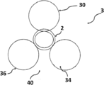
도 2는 셸 및 튜브형 종류 열교환기의 개략도를 도시하고;
도 3은 셸 및 튜브형 사행 흐름 열교환기의 개략도를 도시하고;
도 4는 셸 및 튜브형 나선 흐름 열교환기의 개략도를 도시하고;
도 5는 본 발명에 따른 셸 및 튜브형 종류 열교환기에서 사용될 수 있는 핀을 가진 튜브의 일부를 도시하고;
도 6a는 본 발명에 따른 셸 및 튜브형 종류 열교환기에서 사용될 수 있는 핀을 가진 튜브의 핀들의 나선형 추세(trend)를 개략적으로 도시하고;
도 6b는 본 발명에 따른 셸 및 튜브형 종류 열교환기에서 사용될 수 있는 핀을 가진 튜브의 핀의 프로파일에 할입(interruption)되는 그루브의 나선형 추세를 개략적으로 도시하고;
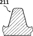
도 7a 내지 도 7c는 본 발명에 따른 셸 및 튜브형 종류 열교환기에서 사용될 수 있는 핀을 가진 튜브의 핀의 대안적인 프로파일의 단면을 도시하고;
도 8은 본 발명에 따른 셸 및 튜브형 종류 열교환기에서 사용될 수 있는 매끈한 부분이 핀 부분 내에 할입된 핀을 가진 튜브의 일부를 도시하고;
도 9는 본 발명에 따른 핀을 가진 튜브를 제조하는 방법을 구현하는 기계의 제 1 실시형태의 개략 측면도이고;
도 10은 도 9의 기계의 개략 정면도이고;
도 11a는 본 발명에 따른 핀을 가진 튜브를 제조하는 방법으로 튜브 상에 제 1 핀/그루브를 형성하는 것을 개략적으로 도시하고;
도 11b는 본 발명에 따른 핀을 가진 튜브를 제조하는 방법으로 튜브 상에 (근간의) 제 2 핀을 형성하는 것을 개략적으로 도시하고;
도 12는 본 발명에 따른 핀을 가진 튜브를 제조하는 방법을 구현하는 기계의 제 2 실시형태의 개략 측면도이고;
도 13은 도 12의 기계의 개략 정면도이고;
도 14는 본 발명에 따른 셸 및 튜브형 종류 열교환기의 개략도를 도시하고;
도 15는 도 14의 셸 및 튜브형 종류 열교환기의 세부를 도시한다.
Claims (10)
- 격납 케이싱(101) 및 복수의 그리드(grid) 형상의 배플(102)을 포함하는 셸 및 튜브형 종류 열교환기(shell and tube longitudinal flow heat exchanger; 1)로서,
상기 격납 케이싱(101)의 내부에서 제 1 유체가 상기 케이싱(101)의 종축선에 대해 실질적으로 평행하게 흐를 수 있고, 상기 격납 케이싱(101)은 그 내부에 실질적으로 서로에 대해 그리고 상기 케이싱(101)의 종축선에 대해 평행한 튜브(2)의 다발을 수용하고,
상기 배플(102)은 상기 케이싱(101)의 종축선에 대해 실질적으로 횡방향이고, 상기 배플(102)은 상기 튜브(2)를 지지하고, 상기 튜브(2)의 다발은 그 내부의 제 2 유체의 흐름에 적합하도록 구성되어 있고,
상기 튜브(2)의 외면의 적어도 일부 상에는 복수의 낮은 핀(21)이 제공되고, 상기 낮은 핀(21)은 상기 튜브(2)의 외면 상에 제 1 진각(angle of advancement; α)으로 나선형으로 배치되고, 상기 낮은 핀(21)은 제 2 나선형 진각(β)(α ≠ β)을 갖는 나선형 그루브(22)가 할입(interruption)된 프로파일을 갖는,
셸 및 튜브형 종류 열교환기. - 제 1 항에 있어서,
상기 낮은 핀(21)은 2 mm 이하, 바람직하게는 0.5 내지 1.5 mm의 높이(H)를 갖는,
셸 및 튜브형 종류 열교환기(1). - 제 1 항에 있어서,
상기 제 1 진각(α)은 80° 미만, 바람직하게는 15° ≤ α ≤ 60°, 더 바람직하게는 20° ≤ α ≤ 45°인,
셸 및 튜브형 종류 열교환기(1). - 제 1 항 내지 제 3 항 중 어느 한 항에 있어서,
상기 제 1 진각(α)과 상기 제 2 진각(β) 사이의 상대 각도는 0° 내지 90°, 바람직하게는 30° 내지 60°인,
셸 및 튜브형 종류 열교환기(1). - 제 1 항 내지 제 4 항 중 어느 한 항에 있어서,
상기 튜브(2)의 내면 상에는 복수의 낮은 핀이 제공되는,
셸 및 튜브형 종류 열교환기(1). - 제 1 항 내지 제 5 항 중 어느 한 항에 있어서,
상기 튜브(2)에는 매끈한 부분(200)이 개재되는 핀 부분(20)이 제공되는,
셸 및 튜브형 종류 열교환기(1). - 가공 조립체(30, 50) 및 하나 이상의 지지 조립체(40, 70)를 포함하고, 상기 제 1 가공 조립체(30, 50)는 제 1 회전식 피닝 공구(32) 및 동일한 구동 축선(33) 상에 순차적으로 장착되는 제 2 회전식 피닝 공구(31)를 포함하고, 상기 제 1 회전식 피닝 공구(32)에는 제 1 진각(α1)을 가진 제 1 나선 가공 프로파일이 제공되고, 상기 제 2 회전식 피닝 공구(31)에는 제 2 진각(α2)(α2≠α1)을 가진 제 2 나선 가공 프로파일이 제공되는 기계(3, 5)를 사용하여 핀을 가진 튜브(2)를 제조하는 방법으로서,
상기 방법은 상기 지지 조립체(40, 70)에 의해 형성되는 평면 상에서 상기 튜브(2)를 전진시키는 단계, 상기 제 1 회전식 피닝 공구(32)에 의해 상기 튜브(2) 상에 제 1 핀(22)을 형성하는 단계, 및 상기 제 2 회전식 피닝 공구(31)에 의해 상기 튜브(2) 상에 제 2 핀(21)을 형성하는 단계를 포함하고,
상기 제 2 핀(21)의 형성은 상기 제 2 핀(21)의 형성의 직후에 실시되고, 상기 제 1 핀(22)의 높이는 상기 제 2 핀(21)의 높이보다 낮은,
핀을 가진 튜브를 제조하는 방법. - 제 7 항에 있어서,
상기 제 1 진각(α1)과 상기 제 2 진각(α2) 사이의 상대 각도는 0° 내지 90°, 바람직하게는 30° 내지 60°이고, 상기 제 1 핀의 높이(h)는 0.5 mm 이하이고, 상기 제 2 핀의 높이(H)는 2 mm 이하인,
핀을 가진 튜브를 제조하는 방법. - 제 7 항 또는 제 8 항에 따라 얻어지는 열교환기(1, 10, 100)를 위한, 특히 셸 및 튜브형 열교환기(1)를 위한,
핀을 가진 튜브(2). - 제 9 항에 있어서,
상기 핀을 가진 튜브(2)의 외면의 적어도 일부 상에는 복수의 낮은 핀(21)이 제공되고, 상기 낮은 핀(21)은 상기 튜브(2)의 외면 상에 제 1 진각(α)으로 나선형으로 배치되고, 상기 낮은 핀(21)은 제 2 나선형 진각(β)(α ≠ β)을 가진 나선형 그루브(22)가 할입되는 프로파일을 가지며, 상기 제 1 진각(α)은 바람직하게는 80° 미만, 더 바람직하게는 15° ≤ α ≤ 60°이고, 상기 제 1 진각(α)과 상기 제 2 진각(β) 사이의 상대 각도는 바람직하게는 0° 내지 90°, 더 바람직하게는 30° 내지 60°이고, 상기 낮은 핀(21)은 바람직하게는 2 mm 이하, 더 바람직하게는 0.5 내지 1.5 mm의 높이(H)를 갖는,
핀을 가진 튜브(2).
Applications Claiming Priority (3)
| Application Number | Priority Date | Filing Date | Title |
|---|---|---|---|
| ITUB2015A009298A ITUB20159298A1 (it) | 2015-12-23 | 2015-12-23 | Scambiatore di calore a fascio tubiero e mantello, tubi alettati per tale scambiatore e relativo metodo di produzione. |
| IT102015000086994 | 2015-12-23 | ||
| PCT/EP2016/078809 WO2017108330A1 (en) | 2015-12-23 | 2016-11-25 | Shell and tube heat exchanger, finned tubes for such heat exchanger and corresponding method |
Publications (1)
| Publication Number | Publication Date |
|---|---|
| KR20180098304A true KR20180098304A (ko) | 2018-09-03 |
Family
ID=55697346
Family Applications (1)
| Application Number | Title | Priority Date | Filing Date |
|---|---|---|---|
| KR1020187020540A Ceased KR20180098304A (ko) | 2015-12-23 | 2016-11-25 | 셸 및 튜브형 열교환기, 이러한 열교환기용 핀을 가진 튜브, 및 대응하는 방법 |
Country Status (9)
| Country | Link |
|---|---|
| US (2) | US20180372427A1 (ko) |
| EP (1) | EP3394550B1 (ko) |
| JP (1) | JP2019502084A (ko) |
| KR (1) | KR20180098304A (ko) |
| CN (1) | CN108431538A (ko) |
| DK (1) | DK3394550T3 (ko) |
| ES (1) | ES2944546T3 (ko) |
| IT (1) | ITUB20159298A1 (ko) |
| WO (1) | WO2017108330A1 (ko) |
Families Citing this family (5)
| Publication number | Priority date | Publication date | Assignee | Title |
|---|---|---|---|---|
| CN108759184B (zh) * | 2018-08-13 | 2024-05-10 | 珠海格力电器股份有限公司 | 冷凝管及冷凝器 |
| CN109489456A (zh) * | 2018-11-28 | 2019-03-19 | 江阴市森博特种换热设备有限公司 | 一种高换热效率的碳化硅列管换热器 |
| CN110763047B (zh) * | 2019-11-18 | 2024-11-15 | 中国恩菲工程技术有限公司 | 管壳式蒸发器 |
| KR20230110247A (ko) | 2020-11-17 | 2023-07-21 | 빌란트-베르케악티엔게젤샤프트 | 다관형 열교환기 |
| CN115397184B (zh) * | 2021-05-25 | 2025-09-02 | 英业达科技有限公司 | 电子装置及散热组件 |
Family Cites Families (13)
| Publication number | Priority date | Publication date | Assignee | Title |
|---|---|---|---|---|
| GB1359647A (en) * | 1971-10-12 | 1974-07-10 | Dewandre Co Ltd C | Heat transfer tubes |
| US4660630A (en) * | 1985-06-12 | 1987-04-28 | Wolverine Tube, Inc. | Heat transfer tube having internal ridges, and method of making same |
| US5141049A (en) * | 1990-08-09 | 1992-08-25 | The Badger Company, Inc. | Treatment of heat exchangers to reduce corrosion and by-product reactions |
| CN1084876C (zh) * | 1994-08-08 | 2002-05-15 | 运载器有限公司 | 传热管 |
| DE69525594T2 (de) * | 1994-11-17 | 2002-08-22 | Carrier Corp., Syracuse | Wärmeaustauschrohr |
| US5697430A (en) * | 1995-04-04 | 1997-12-16 | Wolverine Tube, Inc. | Heat transfer tubes and methods of fabrication thereof |
| US5933953A (en) * | 1997-03-17 | 1999-08-10 | Carrier Corporation | Method of manufacturing a heat transfer tube |
| CA2230213C (en) * | 1997-03-17 | 2003-05-06 | Xin Liu | A heat transfer tube and method of manufacturing same |
| US6176302B1 (en) * | 1998-03-04 | 2001-01-23 | Kabushiki Kaisha Kobe Seiko Sho | Boiling heat transfer tube |
| US6182743B1 (en) * | 1998-11-02 | 2001-02-06 | Outokumpu Cooper Franklin Inc. | Polyhedral array heat transfer tube |
| US6176301B1 (en) * | 1998-12-04 | 2001-01-23 | Outokumpu Copper Franklin, Inc. | Heat transfer tube with crack-like cavities to enhance performance thereof |
| CN100437011C (zh) * | 2005-12-13 | 2008-11-26 | 金龙精密铜管集团股份有限公司 | 一种电制冷机组用满液式铜蒸发换热管 |
| DE102006008083B4 (de) * | 2006-02-22 | 2012-04-26 | Wieland-Werke Ag | Strukturiertes Wärmeaustauscherrohr und Verfahren zu dessen Herstellung |
-
2015
- 2015-12-23 IT ITUB2015A009298A patent/ITUB20159298A1/it unknown
-
2016
- 2016-11-25 US US16/063,378 patent/US20180372427A1/en not_active Abandoned
- 2016-11-25 KR KR1020187020540A patent/KR20180098304A/ko not_active Ceased
- 2016-11-25 ES ES16810268T patent/ES2944546T3/es active Active
- 2016-11-25 WO PCT/EP2016/078809 patent/WO2017108330A1/en not_active Ceased
- 2016-11-25 EP EP16810268.9A patent/EP3394550B1/en active Active
- 2016-11-25 JP JP2018533675A patent/JP2019502084A/ja active Pending
- 2016-11-25 CN CN201680074849.0A patent/CN108431538A/zh active Pending
- 2016-11-25 DK DK16810268.9T patent/DK3394550T3/da active
-
2020
- 2020-10-20 US US17/074,740 patent/US20210033351A1/en not_active Abandoned
Also Published As
| Publication number | Publication date |
|---|---|
| US20180372427A1 (en) | 2018-12-27 |
| EP3394550B1 (en) | 2023-04-05 |
| WO2017108330A1 (en) | 2017-06-29 |
| JP2019502084A (ja) | 2019-01-24 |
| EP3394550A1 (en) | 2018-10-31 |
| ES2944546T3 (es) | 2023-06-22 |
| US20210033351A1 (en) | 2021-02-04 |
| ITUB20159298A1 (it) | 2017-06-23 |
| CN108431538A (zh) | 2018-08-21 |
| DK3394550T3 (da) | 2023-05-01 |
Similar Documents
| Publication | Publication Date | Title |
|---|---|---|
| US20210033351A1 (en) | Shell and tube heat exchanger, finned tubes for such heat exchanger and corresponding method | |
| US6488078B2 (en) | Heat-exchanger tube structured on both sides and a method for its manufacture | |
| EP2232187B1 (en) | Heat transfer tube | |
| US3779312A (en) | Internally ridged heat transfer tube | |
| JP5376763B2 (ja) | 熱交換器管 | |
| US20050241150A1 (en) | Method of manufacture of heat-exchanger tube structured on both sides | |
| CN1575403A (zh) | 换热器翅片管、换热器及其制造方法 | |
| EP2917674B1 (en) | Evaporation heat transfer tube with a hollow cavity | |
| WO2014072047A1 (en) | Evaporation heat transfer tube | |
| MY168235A (en) | Production method of tube-grasping body for grasping an insert tube in a heat exchanger, and production method of heat exchanger using apparatus utilizing such tube-grasping body, and air-conditioner and/or its outdoor unit with a heat exchanger produced by such method and/or apparatus | |
| JP2011106746A (ja) | 伝熱管、熱交換器及び伝熱管加工品 | |
| EP2735386A2 (en) | Heat exchanger and method for manufacturing same | |
| EP3406997B1 (en) | Entwined tubular arrangements for heat exchangers and counterflow heat transfer systems | |
| EP3218664B1 (en) | Fin for a finned pack for heat exchangers, as well as heat exchanger | |
| EP2941610B1 (en) | Tubing element for a heat exchanger means | |
| EP4090901B1 (en) | Energy exchange device between media with improved structure and performances | |
| JP2004322141A (ja) | ヘアピン曲げ銅管および銅管のヘアピン曲げ加工方法 | |
| JP2010133581A (ja) | ヒートパイプ用内面溝付管及びヒートパイプ | |
| JP2010185610A (ja) | 熱交換器及び伝熱管 | |
| JP2012200769A (ja) | 熱交換器用扁平管及びその製造方法 | |
| Tangsri et al. | Influences of total reduction of area on drawing stress and tube dimension in inner spiral ribbed copper tube sinking | |
| JP2006130558A (ja) | 熱交換器の製造方法 | |
| EP3653981B1 (en) | C-shaped heat exchanger tube and nested bundle of c-shaped heat exchanger tubes | |
| JP2003062610A (ja) | 内面傾斜フィン付伝熱管の製造方法 | |
| JP2024087621A (ja) | 内面螺旋溝付伝熱管とその設計方法および熱交換器 |
Legal Events
| Date | Code | Title | Description |
|---|---|---|---|
| PA0105 | International application |
Patent event date: 20180717 Patent event code: PA01051R01D Comment text: International Patent Application |
|
| PG1501 | Laying open of application | ||
| A201 | Request for examination | ||
| PA0201 | Request for examination |
Patent event code: PA02012R01D Patent event date: 20211001 Comment text: Request for Examination of Application |
|
| E902 | Notification of reason for refusal | ||
| PE0902 | Notice of grounds for rejection |
Comment text: Notification of reason for refusal Patent event date: 20230504 Patent event code: PE09021S01D |
|
| E601 | Decision to refuse application | ||
| PE0601 | Decision on rejection of patent |
Patent event date: 20230711 Comment text: Decision to Refuse Application Patent event code: PE06012S01D Patent event date: 20230504 Comment text: Notification of reason for refusal Patent event code: PE06011S01I |