KR20180098229A - Stator coil, method of manufacturing stator and rotating electric machine - Google Patents
Stator coil, method of manufacturing stator and rotating electric machine Download PDFInfo
- Publication number
- KR20180098229A KR20180098229A KR1020187013907A KR20187013907A KR20180098229A KR 20180098229 A KR20180098229 A KR 20180098229A KR 1020187013907 A KR1020187013907 A KR 1020187013907A KR 20187013907 A KR20187013907 A KR 20187013907A KR 20180098229 A KR20180098229 A KR 20180098229A
- Authority
- KR
- South Korea
- Prior art keywords
- coil
- slot
- coil portion
- diameter side
- stator core
- Prior art date
- Legal status (The legal status is an assumption and is not a legal conclusion. Google has not performed a legal analysis and makes no representation as to the accuracy of the status listed.)
- Withdrawn
Links
Images


Classifications
-
- H—ELECTRICITY
- H02—GENERATION; CONVERSION OR DISTRIBUTION OF ELECTRIC POWER
- H02K—DYNAMO-ELECTRIC MACHINES
- H02K3/00—Details of windings
- H02K3/04—Windings characterised by the conductor shape, form or construction, e.g. with bar conductors
- H02K3/28—Layout of windings or of connections between windings
-
- H—ELECTRICITY
- H02—GENERATION; CONVERSION OR DISTRIBUTION OF ELECTRIC POWER
- H02K—DYNAMO-ELECTRIC MACHINES
- H02K1/00—Details of the magnetic circuit
- H02K1/06—Details of the magnetic circuit characterised by the shape, form or construction
- H02K1/12—Stationary parts of the magnetic circuit
- H02K1/16—Stator cores with slots for windings
- H02K1/165—Shape, form or location of the slots
-
- H—ELECTRICITY
- H02—GENERATION; CONVERSION OR DISTRIBUTION OF ELECTRIC POWER
- H02K—DYNAMO-ELECTRIC MACHINES
- H02K1/00—Details of the magnetic circuit
- H02K1/06—Details of the magnetic circuit characterised by the shape, form or construction
- H02K1/22—Rotating parts of the magnetic circuit
- H02K1/27—Rotor cores with permanent magnets
- H02K1/2706—Inner rotors
- H02K1/272—Inner rotors the magnetisation axis of the magnets being perpendicular to the rotor axis
- H02K1/274—Inner rotors the magnetisation axis of the magnets being perpendicular to the rotor axis the rotor consisting of two or more circumferentially positioned magnets
- H02K1/2753—Inner rotors the magnetisation axis of the magnets being perpendicular to the rotor axis the rotor consisting of two or more circumferentially positioned magnets the rotor consisting of magnets or groups of magnets arranged with alternating polarity
-
- H—ELECTRICITY
- H02—GENERATION; CONVERSION OR DISTRIBUTION OF ELECTRIC POWER
- H02K—DYNAMO-ELECTRIC MACHINES
- H02K15/00—Processes or apparatus specially adapted for manufacturing, assembling, maintaining or repairing of dynamo-electric machines
- H02K15/02—Processes or apparatus specially adapted for manufacturing, assembling, maintaining or repairing of dynamo-electric machines of stator or rotor bodies
- H02K15/021—Magnetic cores
-
- H—ELECTRICITY
- H02—GENERATION; CONVERSION OR DISTRIBUTION OF ELECTRIC POWER
- H02K—DYNAMO-ELECTRIC MACHINES
- H02K15/00—Processes or apparatus specially adapted for manufacturing, assembling, maintaining or repairing of dynamo-electric machines
- H02K15/02—Processes or apparatus specially adapted for manufacturing, assembling, maintaining or repairing of dynamo-electric machines of stator or rotor bodies
- H02K15/03—Processes or apparatus specially adapted for manufacturing, assembling, maintaining or repairing of dynamo-electric machines of stator or rotor bodies having permanent magnets
-
- H—ELECTRICITY
- H02—GENERATION; CONVERSION OR DISTRIBUTION OF ELECTRIC POWER
- H02K—DYNAMO-ELECTRIC MACHINES
- H02K15/00—Processes or apparatus specially adapted for manufacturing, assembling, maintaining or repairing of dynamo-electric machines
- H02K15/04—Processes or apparatus specially adapted for manufacturing, assembling, maintaining or repairing of dynamo-electric machines of windings prior to their mounting into the machines
- H02K15/043—Processes or apparatus specially adapted for manufacturing, assembling, maintaining or repairing of dynamo-electric machines of windings prior to their mounting into the machines winding flat conductive wires or sheets
- H02K15/0432—Distributed windings
-
- H—ELECTRICITY
- H02—GENERATION; CONVERSION OR DISTRIBUTION OF ELECTRIC POWER
- H02K—DYNAMO-ELECTRIC MACHINES
- H02K15/00—Processes or apparatus specially adapted for manufacturing, assembling, maintaining or repairing of dynamo-electric machines
- H02K15/06—Embedding prefabricated windings in the machines
- H02K15/062—Windings in slots; Salient pole windings
- H02K15/065—Windings consisting of complete sections, e.g. coils or waves
- H02K15/066—Windings consisting of complete sections, e.g. coils or waves inserted perpendicularly to the axis of the slots or inter-polar channels
-
- H—ELECTRICITY
- H02—GENERATION; CONVERSION OR DISTRIBUTION OF ELECTRIC POWER
- H02K—DYNAMO-ELECTRIC MACHINES
- H02K23/00—DC commutator motors or generators having mechanical commutator; Universal AC/DC commutator motors
- H02K23/26—DC commutator motors or generators having mechanical commutator; Universal AC/DC commutator motors characterised by the armature windings
- H02K23/30—DC commutator motors or generators having mechanical commutator; Universal AC/DC commutator motors characterised by the armature windings having lap or loop windings
-
- H—ELECTRICITY
- H02—GENERATION; CONVERSION OR DISTRIBUTION OF ELECTRIC POWER
- H02K—DYNAMO-ELECTRIC MACHINES
- H02K3/00—Details of windings
- H02K3/04—Windings characterised by the conductor shape, form or construction, e.g. with bar conductors
- H02K3/12—Windings characterised by the conductor shape, form or construction, e.g. with bar conductors arranged in slots
-
- H—ELECTRICITY
- H02—GENERATION; CONVERSION OR DISTRIBUTION OF ELECTRIC POWER
- H02K—DYNAMO-ELECTRIC MACHINES
- H02K3/00—Details of windings
- H02K3/46—Fastening of windings on the stator or rotor structure
- H02K3/48—Fastening of windings on the stator or rotor structure in slots
-
- H—ELECTRICITY
- H02—GENERATION; CONVERSION OR DISTRIBUTION OF ELECTRIC POWER
- H02K—DYNAMO-ELECTRIC MACHINES
- H02K1/00—Details of the magnetic circuit
- H02K1/06—Details of the magnetic circuit characterised by the shape, form or construction
- H02K1/12—Stationary parts of the magnetic circuit
- H02K1/14—Stator cores with salient poles
- H02K1/146—Stator cores with salient poles consisting of a generally annular yoke with salient poles
- H02K1/148—Sectional cores
Landscapes
- Engineering & Computer Science (AREA)
- Power Engineering (AREA)
- Manufacturing & Machinery (AREA)
- Windings For Motors And Generators (AREA)
- Manufacture Of Motors, Generators (AREA)
Abstract
이 회전 전기 기기는, 코일을 포함하고, 코일은, 슬롯의 외경측에 배치되는 단층 중첩권 코일로 이루어지는 제1 코일부와, 제1 코일부에 연속하여 접속되는 제1 접속선부에 연속하여 접속되고, 슬롯의 내경측에 배치되는 단층 중첩권 코일로 이루어지는 제2 코일부와, 2층 중첩권 코일로 이루어지는 제3 코일부를 복수 포함하는 제3 코일부군을 포함한다.The rotating electric machine includes a coil, and the coil includes a first coil portion made of a single layer superposed coil disposed on the outer diameter side of the slot, and a second coil portion connected to the first connecting portion continuously connected to the first coil portion And a third coil group including a plurality of third coil portions each composed of a two-layer superposed winding coil.
Description
본 발명은 스테이터 코일, 스테이터의 제조 방법 및 회전 전기 기기에 관한 것이다.The present invention relates to a stator coil, a method for manufacturing a stator, and a rotating electrical machine.
종래, 코일 중 슬롯에 배치되는 한 쌍의 슬롯 수용부의 한쪽이 슬롯의 외경측에 배치됨과 함께, 한 쌍의 슬롯 수용부의 다른 쪽이 슬롯의 내경측에 배치되는 2층 중첩권 코일을 구비한 회전 전기 기기가 알려져 있다. 이러한 회전 전기 기기는, 예를 들어, 일본 특허 공개 제2009-195004호 공보에 개시되어 있다.One of the pair of slot accommodating portions disposed in the slots of the coils is disposed on the outer diameter side of the slots and the other of the pair of slot accommodating portions is arranged on the inner diameter side of the slot. Electric devices are known. Such a rotating electrical machine is disclosed in, for example, Japanese Patent Application Laid-Open No. 2009-195004.
일본 특허 공개 제2009-195004호 공보에 기재된 회전 전기 기기에서는, 인접하도록 배치되는 2개의 2층 중첩권 코일 중, 한쪽의 2층 중첩권 코일의 슬롯 수용부가 슬롯의 외경측에 배치되고, 다른 쪽의 2층 중첩권 코일의 슬롯 수용부가, 한쪽의 2층 중첩권 코일의 슬롯 수용부가 배치되는 것과 동일한 슬롯의 내경측에 배치되어 있다. 또한, 일본 특허 공개 제2009-195004호 공보에 기재된 회전 전기 기기에서는, 복수의 슬롯 모두에 2층 중첩권 코일이 배치되어 있다.In the rotating electrical machine described in Japanese Patent Laid-Open Publication No. 2009-195004, among the two two-layer superposed winding coils arranged so as to be adjacent to each other, the slot accommodating portion of one of the two-layer superposed winding coils is arranged on the outer diameter side of the slot, Of the two-layer superposition coil is disposed on the inner diameter side of the same slot in which the slot accommodating portion of the two-layer superposed coil is disposed. Further, in the rotating electrical machine described in Japanese Patent Application Laid-Open No. 2009-195004, a two-layer superposed winding coil is disposed in all of a plurality of slots.
여기서, 일본 특허 공개 제2009-195004호 공보에 기재된 회전 전기 기기에서는, 2층 중첩권 코일을 하나씩 슬롯에 배치해 갔을 경우, 처음에 배치된 2층 중첩권 코일의 슬롯 수용부와, 최후의 2층 중첩권 코일의 슬롯 수용부가, 동일한 슬롯에 배치된다. 이 때문에, 처음에 배치된 2층 중첩권 코일의 슬롯 수용부를 일단 슬롯으로부터 제거한 상태에서, 마지막으로 배치되는 2층 중첩권 코일의 슬롯 수용부를 슬롯에 배치한 후, 일단 슬롯으로부터 제거된 처음에 배치된 2층 중첩권 코일의 슬롯 수용부를 다시 슬롯에 배치할 필요가 있다. 그래서, 처음에 스테이터 코어(슬롯)에 배치되는 1개의 중첩권 코일과, 마지막으로 스테이터 코어에 배치되는 다른 중첩권 코일을, 단층 중첩권 코일로서 구성하고, 처음에 슬롯의 안측에 하나의 단층 중첩권 코일을 배치하고, 2층 중첩권 코일을 스테이터 코어에 배치한 후, 마지막으로 슬롯의 전방측에 다른 단층 중첩권 코일을 배치하는 구성이 생각된다.Here, in the rotary electric machine disclosed in Japanese Patent Laid-Open Publication No. 2009-195004, when two stacked superposed winding coils are arranged one by one in the slots, the slot accommodating portion of the two-layer superposed winding coils disposed at the beginning, The slot accommodating portions of the layer overlapping winding coils are disposed in the same slot. Therefore, in the state where the slot accommodating portion of the two-layer superposed winding coil disposed at the beginning is removed from the one-end slot, the slot accommodating portion of the last two stacked superposed coil is disposed in the slot, It is necessary to dispose the slot accommodating portion of the two-layer superimposed winding coil in the slot again. Thus, one superposed winding coil initially disposed in the stator core (slot) and finally another superposed winding coil disposed in the stator core are constructed as single layer superposed winding coils, It is conceivable to dispose a winding coil, arrange a two-layer superposed winding coil on the stator core, and finally arrange another single layer superposed winding coil on the front side of the slot.
그러나, 상기 구성의 경우, 슬롯의 안측(외경측 또는 내경측의 한쪽)에만 배치되는 하나의 단층 중첩권 코일과, 슬롯의 전방측(외경측 또는 내경측의 다른 쪽)에만 배치되는 다른 단층 중첩권 코일을 개별로 병렬로 동력선과 접속한 경우에는, 하나의 단층 중첩권 코일과 다른 단층 중첩권 코일의 직경 방향의 배치 위치의 차이에 기인하여, 2층 중첩권 코일에 비하여, 쇄교 자속의 밸런스가 나빠지는 경우가 있을 것으로 생각된다. 이 경우에, 쇄교 자속의 밸런스의 악화를 방지하기 위해서, 하나의 단층 중첩권 코일과 다른 단층 중첩권 코일을, 스테이터 코어에 배치한 후에, 서로 배색(배색 바꿈)을 행하는 것이 생각된다. 이에 의해, 하나의 단층 중첩권 코일과 다른 단층 중첩권 코일을 서로 접속하여, 2층 중첩권 코일과 마찬가지인 쇄교 자속의 밸런스를 갖도록 구성하는 것이 생각된다.However, in the case of the above configuration, one single layer superimposed winding coil disposed only on the inner side (one of the radially outer side and the inner radial side) of the slot and the other single layer superposed on only the front side Layer winding superposed winding coils and the other single layer superposed winding coils are connected to the power lines in parallel with each other in the radial direction, It is thought that there may be a case where it is bad. In this case, in order to prevent the balance of the flux linkage from deteriorating, it is conceivable to arrange the single layer superimposed winding coils and the other single layer superimposed winding coils on the stator core and then perform coloring (color changing) with each other. Thus, it is conceivable that one single layer superposed winding coil and another single layer superposed winding coil are connected to each other so as to have a balance of the flux-linkage similar to that of the two-layer superposed winding coil.
그러나, 하나의 단층 중첩권 코일과 다른 단층 중첩권 코일을 스테이터 코어에 배치 후에 배색(또는 배색 바꿈)하는 작업은, 수작업으로 행할 필요가 있어, 기계화(자동화)하는 것이 곤란하게 된다. 또한, 배색(또는 배색 바꿈)하기 위해서, 접합 단자 및 절연 부재를 설치하기 위한 스페이스를 확보할 필요가 발생하므로, 스테이터 코일(회전 전기 기기)이 대형화한다는 문제가 있다. 따라서, 상기 구성의 스테이터 코일에서는, 스테이터 코일(회전 전기 기기)의 대형화를 방지하면서, 스테이터 코일의 슬롯에의 배치 작업을 기계화(자동화)하는 것이 곤란하다는 문제점이 있다.However, the operation of coloring (or changing the coloring) after arranging one single-layer superposed-winding coil and another single-layer superposed-winding coil in the stator core needs to be performed by hand, making it difficult to mechanize (automate). In addition, there is a problem that the stator coil (rotating electric machine) becomes large in size because it is necessary to secure a space for installing the junction terminal and the insulating member in order to color (or change color). Therefore, in the stator coil having the above-described structure, there is a problem in that it is difficult to mechanize (automate) the arrangement work of the stator coil in the slot while preventing the stator coil (rotating electrical machine) from becoming larger.
본 발명은 상기와 같은 과제를 해결하기 위하여 이루어진 것이며, 본 발명의 하나의 목적은, 스테이터 코일(회전 전기 기기)의 대형화를 방지하면서, 스테이터 코일의 슬롯에의 배치 작업의 기계화(자동화)를 용이하게 실현하는 것이 가능한 스테이터 코일, 스테이터의 제조 방법 및 회전 전기 기기를 제공하는 것이다.SUMMARY OF THE INVENTION The present invention has been made in order to solve the above problems, and an object of the present invention is to provide a stator for a stator, which is capable of facilitating the machining (automation) A method of manufacturing a stator, and a rotating electrical machine.
상기 목적을 달성하기 위해서, 본 발명의 제1 국면에 있어서의 스테이터 코일은, 스테이터 코어에 배치되는 코일이며, 코일은, 제1 슬롯의 외경측 및 제2 슬롯의 외경측에 배치되는 한 쌍의 제1 슬롯 수용부를 포함하는 단층 중첩권 코일로 이루어지는 제1 코일부와, 제1 코일부에 연속하여 접속되는 한쪽 단부를 갖는 제1 접속선부의 다른 쪽 단부에 연속하여 접속되고, 제1 슬롯의 내경측에 한쪽이 배치됨과 함께, 제1 슬롯 및 제2 슬롯과는 다른 제3 슬롯의 내경측에 다른 쪽이 배치되는 한 쌍의 제2 슬롯 수용부를 포함하는 단층 중첩권 코일로 이루어지는 제2 코일부와, 2층 중첩권 코일로 이루어지는 제3 코일부를 복수 포함하는 제3 코일부군을 포함하고, 제3 코일부군의 둘레 방향 한쪽 단부의 제3 슬롯 수용부가, 제2 슬롯의 내경측에 배치되고, 제3 코일부군의 둘레 방향 다른 쪽 단부의 제3 슬롯 수용부가 제3 슬롯의 외경측에 배치되어 있다.In order to attain the above object, a stator coil according to a first aspect of the present invention is a coil disposed in a stator core, and the coil includes a pair of coils disposed on an outer diameter side of the first slot and an outer diameter side of the second slot Layered superposed winding coil including the first slot accommodating portion and the other end portion of the first connecting wire portion having one end continuously connected to the first coil portion, And a pair of second slot accommodating portions disposed on the inner diameter side of the first slot and the other of which is disposed on the inner diameter side of the third slot different from the first slot and the second slot, And a third coil unit group including a plurality of third coil units made up of a two-layer superposed coil, wherein the third slot unit at one end in the circumferential direction of the third coil unit group is disposed on the inner diameter side of the second slot And the third coil part And the third slot accommodating portion at the other end in the circumferential direction of the group is disposed on the outer diameter side of the third slot.
본 발명의 제1 국면에 의한 스테이터 코일에서는, 상기와 같이 구성함으로써, 예를 들어, 스테이터 코어의 외경측에 슬롯이 개구하고 있는 경우, 제1 코일부를 스테이터 코어의 외부(예를 들어, 스테이터 코어의 내경측)에 퇴피시킨 상태에서, 처음에 단층 중첩권 코일로 이루어지는 제2 코일부를 스테이터 코어에 배치하고, 2층 중첩권 코일로 이루어지는 제3 코일부를 복수 포함하는 제3 코일부군을 스테이터 코어에 배치한 후, 마지막으로 스테이터 코어의 외부에 배치(퇴피)되어 있었던 제1 코일부를 스테이터 코어에 배치할 수 있다. 이에 의해, 처음에 배치된 2층 중첩권 코일의 슬롯 수용부를 일단 슬롯으로부터 제거시킬 필요가 없고, 제1 코일부와 제2 코일부를, 스테이터 코어에 배치한 후에, 제1 코일부와 제2 코일부를 배색(또는 배색 바꿈)할 필요가 없으므로, 스테이터 코일의 슬롯에의 배치 작업의 기계화(자동화)를 용이하게 실현할 수 있다. 또한, 제1 코일부와 제2 코일부를, 스테이터 코어에 배치한 후에, 제1 코일부와 제2 코일부를 배색(또는 배색 바꿈)할 필요가 없으므로, 배색(또는 배색 바꿈)하기 위한 접합 단자 및 절연 부재를 설치하기 위한 스페이스가 불필요해져, 스테이터 코일(회전 전기 기기)이 대형화하는 것을 방지할 수 있다. 그 결과, 스테이터 코일(회전 전기 기기)의 대형화를 방지하면서, 스테이터 코일의 슬롯에의 배치 작업의 기계화(자동화)를 용이하게 실현할 수 있다.In the stator coil according to the first aspect of the present invention, for example, when the slot is opened on the outer diameter side of the stator core, the first coil part is connected to the outside of the stator core Layered superposed winding coil is disposed on the stator core and the third coil group including a plurality of third coil portions composed of two-layer superposed winding coils is wound around the stator core, The first coil part disposed (retracted) to the outside of the stator core can be disposed in the stator core after the stator core is disposed in the stator core. Thereby, it is not necessary to remove the slot accommodating portion of the two-layer stacked winding coils initially disposed from the slot at one time, and after the first coil portion and the second coil portion are disposed in the stator core, It is not necessary to color (or change the color of) the coil part, so that the mechanization (automation) of the arrangement work of the stator coil in the slot can be easily realized. Further, since the first coil portion and the second coil portion do not need to be colored (or color changed) after the first coil portion and the second coil portion are arranged in the stator core, a joint for coloring The space for installing the terminals and the insulating member becomes unnecessary, and the stator coil (rotating electric machine) can be prevented from becoming larger. As a result, it is possible to easily realize the mechanization (automation) of the arrangement work of the stator coil in the slots while preventing the stator coil (rotating electric machine) from becoming larger.
본 발명의 제2 국면에 있어서의 스테이터의 제조 방법은, 서로 다른 슬롯인 제1 슬롯, 제2 슬롯 및 제3 슬롯을 갖는 스테이터 코어를 포함하는, 스테이터의 제조 방법이며, 스테이터 코어의 제1 슬롯의 외경측 및 제2 슬롯의 외경측에 배치되는 한 쌍의 제1 슬롯 수용부를 포함하는 단층 중첩권 코일로 이루어지는 제1 코일부와, 제1 코일부에 연속하여 접속되는 한쪽 단부를 갖는 제1 접속선부의 다른 쪽 단부에 연속하여 접속되고, 제1 슬롯의 내경측에 한쪽이 배치됨과 함께, 제1 슬롯 및 제2 슬롯과는 다른 제3 슬롯의 내경측에 다른 쪽이 배치되는 한 쌍의 제2 슬롯 수용부를 포함하는 단층 중첩권 코일로 이루어지는 제2 코일부 중 한쪽을, 스테이터 코어의 외부로 퇴피시킨 상태에서, 다른 쪽을 스테이터 코어에 배치하고, 그 후, 2층 중첩권 코일로 이루어지는 제3 코일부를 복수 포함하는 제3 코일부군의 둘레 방향 한쪽 단부의 제3 슬롯 수용부를 제2 슬롯의 내경측에 배치함과 함께, 제3 코일부군의 둘레 방향 다른 쪽 단부의 제3 슬롯 수용부를 제3 슬롯의 외경측에 배치하고, 그 후, 스테이터 코어의 외부로 퇴피시키고 있었던 제1 코일부 및 제2 코일부 중 한쪽을 스테이터 코어에 배치한다.A method of manufacturing a stator in a second aspect of the present invention is a method of manufacturing a stator including a stator core having first slots, second slots and third slots, which are different slots, A first coil portion comprising a single layer superposed winding coil including a pair of first slot receiving portions arranged on the outer diameter side of the first coil portion and the outer diameter side of the second slot and a first end portion connected to the first coil portion, And a pair of first and second slots which are connected to the other end of the connection line portion and which are disposed on the inner diameter side of the first slot and which are arranged on the inner diameter side of the third slot different from the first slot and the second slot, One of the second coil portions constituted by the single layer superimposed winding coil including the second slot accommodating portion is retracted to the outside of the stator core and the other is arranged in the stator core and thereafter is made up of a two- G The third coil accommodating portion at one end in the circumferential direction of the third coil group including a plurality of third coil portions is disposed at the inner diameter side of the second slot and the third slot accommodating portion at the third slot The accommodating portion is disposed on the outer diameter side of the third slot, and then one of the first coil portion and the second coil portion retracted to the outside of the stator core is disposed in the stator core.
본 발명의 제2 국면에 의한 스테이터의 제조 방법에서는, 상기와 같이 구성함으로써, 스테이터 코일(회전 전기 기기)의 대형화를 방지하면서, 스테이터 코일의 슬롯에의 배치 작업의 기계화(자동화)를 용이하게 실현 가능한 스테이터의 제조 방법을 제공할 수 있다.In the method for manufacturing a stator according to the second aspect of the present invention, it is possible to easily realize the mechanization (automation) of the positioning operation of the stator coil in the slots while preventing the stator coil It is possible to provide a manufacturing method of a stator as far as possible.
본 발명의 제3 국면에 있어서의 회전 전기 기기는, 영구 자석이 설치되는 로터 코어와, 로터 코어와 반경 방향에 대향하도록 배치되고, 서로 다른 슬롯인 제1 슬롯, 제2 슬롯 및 제3 슬롯을 갖는 스테이터 코어와, 스테이터 코어에 배치된 코일을 구비하고, 코일은, 제1 슬롯의 외경측 및 제2 슬롯의 외경측에 배치되는 한 쌍의 제1 슬롯 수용부를 포함하는 단층 중첩권 코일로 이루어지는 제1 코일부와, 제1 코일부에 연속하여 접속되는 한쪽 단부를 갖는 제1 접속선부의 다른 쪽 단부에 연속하여 접속되고, 제1 슬롯의 내경측에 한쪽이 배치됨과 함께, 제1 슬롯 및 제2 슬롯과는 다른 제3 슬롯의 내경측에 다른 쪽이 배치되는 한 쌍의 제2 슬롯 수용부를 포함하는 단층 중첩권 코일로 이루어지는 제2 코일부와, 2층 중첩권 코일로 이루어지는 제3 코일부를 복수 포함하는 제3 코일부군을 포함하고, 제3 코일부군의 둘레 방향 한쪽 단부의 제3 슬롯 수용부가, 제2 슬롯의 내경측에 배치되고, 제3 코일부군의 둘레 방향 다른 쪽 단부의 제3 슬롯 수용부가 제3 슬롯의 외경측에 배치되어 있다.A rotary electric machine according to a third aspect of the present invention includes a rotor core provided with permanent magnets, and a first slot, a second slot, and a third slot, which are arranged to face the rotor core in the radial direction, And a coil disposed on the outer diameter side of the first slot and a pair of first slot accommodating portions disposed on the outer diameter side of the second slot, the coil including a stator core having a stator core The first coil portion and the other end portion of the first connection wire portion having one end continuously connected to the first coil portion are continuously connected and one of them is disposed on the inner diameter side of the first slot, A second coil portion composed of a single layer superposed winding coil including a pair of second slot accommodating portions in which the other is disposed on the inner diameter side of the third slot different from the second slot, Some of the plural The third coil portion of the third coil group is disposed at the inner diameter side of the second slot and the third slot portion of the third coil portion group is disposed at the other end of the third coil portion in the circumferential direction, And the additional portion is disposed on the outer diameter side of the third slot.
본 발명의 제3 국면에 의한 회전 전기 기기에서는, 상기와 같이 구성함으로써, 제3 국면에 의한 회전 전기 기기에 있어서도, 스테이터 코일(회전 전기 기기)의 대형화를 방지하면서, 스테이터 코일의 슬롯에의 배치 작업의 기계화(자동화)를 용이하게 실현 가능한 회전 전기 기기를 제공할 수 있다.In the rotating electrical machine according to the third aspect of the present invention, even in the rotating electrical machine according to the third aspect, the stator coil (rotating electric machine) can be prevented from becoming larger, It is possible to provide a rotating electrical machine that can easily realize the mechanization (automation) of the work.
본 발명에 따르면, 상기한 바와 같이 스테이터 코일(회전 전기 기기)의 대형화를 방지하면서, 스테이터 코일의 슬롯에의 배치 작업의 기계화(자동화)를 용이하게 실현할 수 있다.According to the present invention, it is possible to easily realize the mechanization (automation) of the positioning operation of the stator coil in the slot while preventing the stator coil (rotating electrical machine) from becoming larger as described above.
도 1은 본 발명의 제1 실시 형태에 의한 회전 전기 기기의 평면도이다.
도 2는 본 발명의 제1 실시 형태에 의한 회전 전기 기기의 코일을 도시하는 도면이다.
도 3은 본 발명의 제1 실시 형태에 의한 회전 전기 기기의 제1 코일부 및 제2 코일부를 도시하는 도면이다.
도 4는 본 발명의 제1 실시 형태에 의한 회전 전기 기기의 제1 접속선부의 길이를 설명하기 위한 도면이다.
도 5는 본 발명의 제1 실시 형태에 의한 회전 전기 기기의 제3 코일부를 도시하는 도면이다.
도 6은 본 발명의 제1 실시 형태에 의한 회전 전기 기기의 제3 코일부의 제조 방법을 설명하기 위한 도 (1)이다.
도 7은 본 발명의 제1 실시 형태에 의한 회전 전기 기기의 제3 코일부의 제조 방법을 설명하기 위한 도 (2)이다.
도 8은 본 발명의 제1 실시 형태에 의한 회전 전기 기기의 제3 코일부의 제조 방법을 설명하기 위한 도 (3)이다.
도 9는 본 발명의 제1 실시 형태에 의한 회전 전기 기기의 제1 코일부 및 제2 코일부의 제조 방법을 설명하기 위한 도면이다.
도 10은 본 발명의 제1 실시 형태에 의한 회전 전기 기기의 제1 코일부의 퇴피와 제2 코일부의 스테이터 코어에의 배치를 설명하기 위한 도 (1)이다.
도 11은 본 발명의 제1 실시 형태에 의한 회전 전기 기기의 제1 코일부의 퇴피와 제2 코일부의 스테이터 코어에의 배치를 설명하기 위한 도 (2)이다.
도 12는 본 발명의 제1 실시 형태에 의한 회전 전기 기기의 제3 코일부의 스테이터 코어에의 배치를 설명하기 위한 도면이다.
도 13은 본 발명의 제1 실시 형태에 의한 회전 전기 기기의 퇴피되어 있었던 제1 코일부의 스테이터 코어에의 배치를 설명하기 위한 도 (1)이다.
도 14는 본 발명의 제1 실시 형태에 의한 회전 전기 기기의 퇴피되어 있었던 제1 코일부의 스테이터 코어에의 배치를 설명하기 위한 도 (2)이다.
도 15는 본 발명의 제2 실시 형태에 의한 회전 전기 기기의 평면도이다.
도 16은 본 발명의 제2 실시 형태에 의한 회전 전기 기기의 제2 코일부의 퇴피와, 제1 코일부 및 제3 코일부의 스테이터 코어에의 배치를 설명하기 위한 도면이다.
도 17은 본 발명의 제2 실시 형태에 의한 회전 전기 기기의 퇴피되어 있었던 제2 코일부의 스테이터 코어에의 배치를 설명하기 위한 도면이다.
도 18은 본 발명의 제1 실시 형태 변형예에 의한 회전 전기 기기의 내주측 코어를 도시한 도면이다.
도 19는 본 발명의 제1 실시 형태 변형예에 의한 회전 전기 기기의 퇴피되어 있었던 제1 코일부의 스테이터 코어에의 배치를 설명하기 위한 도면이다.1 is a plan view of a rotating electrical machine according to a first embodiment of the present invention.
2 is a view showing a coil of a rotating electrical machine according to a first embodiment of the present invention.
3 is a diagram showing a first coil part and a second coil part of a rotating electrical machine according to the first embodiment of the present invention.
4 is a view for explaining the length of the first connecting portion of the rotating electrical machine according to the first embodiment of the present invention.
5 is a diagram showing a third coil part of the rotating electrical machine according to the first embodiment of the present invention.
6 is a view (1) for explaining a method of manufacturing a third coil portion of a rotating electric machine according to the first embodiment of the present invention.
7 is a view (2) for explaining a method of manufacturing a third coil portion of a rotating electric machine according to the first embodiment of the present invention.
8 is a view (3) for explaining a method of manufacturing a third coil portion of a rotating electric machine according to the first embodiment of the present invention.
Fig. 9 is a view for explaining a first coil part and a second coil part of a rotating electrical machine according to the first embodiment of the present invention. Fig.
10 is a view (1) for explaining the retraction of the first coil part of the rotating electrical machine according to the first embodiment of the present invention and the arrangement of the second coil part in the stator core.
11 is a view (2) for explaining the retraction of the first coil portion of the rotating electric machine and the disposition of the second coil portion in the stator core according to the first embodiment of the present invention.
12 is a view for explaining the arrangement of the third coil portion of the rotating electrical machine in the stator core according to the first embodiment of the present invention.
13 is a view (1) for explaining the arrangement of the retracted first coil part in the stator core of the rotating electric machine according to the first embodiment of the present invention.
Fig. 14 is a view (2) for explaining the arrangement of the retracted first coil part in the stator core of the rotating electric machine according to the first embodiment of the present invention; Fig.
15 is a plan view of a rotating electrical machine according to a second embodiment of the present invention.
16 is a view for explaining the retraction of the second coil portion of the rotating electrical machine according to the second embodiment of the present invention and the arrangement of the first coil portion and the third coil portion in the stator core.
17 is a view for explaining the arrangement of the retracted second coil portion in the stator core of the rotating electric machine according to the second embodiment of the present invention.
18 is a view showing an inner peripheral core of a rotating electrical machine according to a modified example of the first embodiment of the present invention.
Fig. 19 is a diagram for explaining the arrangement of the retracted first coil part in the stator core of the rotating electric machine according to the modification of the first embodiment of the present invention. Fig.
이하, 본 발명의 실시 형태를 도면에 기초하여 설명한다.DESCRIPTION OF THE PREFERRED EMBODIMENTS Hereinafter, embodiments of the present invention will be described with reference to the drawings.
[제1 실시 형태][First Embodiment]
(회전 전기 기기의 구조)(Structure of rotating electric machine)
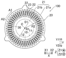
도 1∼도 5를 참조하여, 제1 실시 형태에 의한 회전 전기 기기(100)의 구조에 대하여 설명한다. 도 1에 도시하는 회전 전기 기기(100)는 예를 들어, 모터(바람직하게는, 3상의 브러시리스 모터)이다. 또한, 도 2에, 3상의 코일(30) 중 1상분의 코일(30)만을 도시하고 있다. 또한, 코일(30)은 특허 청구범위의 「스테이터 코일」의 일례이다.The structure of the rotating
또한, 본원 명세서에서는, 간단히 「회전축 방향」 또는 간단히 「축방향」이라고 기재한 경우에는, 회전 전기 기기(100)의 회전축 방향을 의미하고, 도면 중의 Z축에 평행한 방향을 의미한다. 또한, 간단히 「둘레 방향」이라고 기재한 경우에는, 회전 전기 기기(100)의 둘레 방향을 의미하고, 도면 중의 화살표 A1 방향 또는 화살표 A2 방향을 의미한다. 간단히 「직경 방향」이라고 기재한 경우에는, 회전 전기 기기(100)의 직경 방향을 의미하고, 도면 중의 화살표 R1 방향 또는 화살표 R2 방향을 의미한다. 또한, 간단히 「내경측」이라고 기재한 경우에는, 회전 전기 기기(100)의 내경측을 의미하고, 도면 중의 화살표 R1 방향측을 의미하는 것으로서 기재하고 있다. 또한, 간단히 「외경측」이라고 기재한 경우에는, 회전 전기 기기(100)의 외경측을 의미하고, 도면 중의 화살표 R2 방향측을 의미하는 것으로서 기재하고 있다.In the present specification, in the case of simply describing the "rotation axis direction" or simply "axial direction", it means the rotation axis direction of the rotating
도 1에 도시한 바와 같이, 회전 전기 기기(100)는 로터(10)를 구비하고 있다. 로터(10)의 로터 코어(11)에는, 복수의 영구 자석(12)이 설치되어 있다. 복수의 영구 자석(12)은 둘레 방향을 따라, 대략 동일한 각도 간격으로 배치되어 있다.As shown in Fig. 1, the rotating
또한, 회전 전기 기기(100)는 로터 코어(11)의 외주면과 직경 방향에 대향하도록 배치되는 스테이터(20)(스테이터 코어(21))를 구비하고 있다. 스테이터 코어(21)는 내외 분할형의 스테이터 코어(내외 분할 철심)로서 형성되어 있다.The rotating
구체적으로는, 스테이터 코어(21)는 스테이터 코어(21)의 외경측에 배치된 외경측 코어(21a)(외주측 철심)와, 스테이터 코어(21)의 외경측에 배치된 내경측 코어(21b)(내주측 철심)를 포함한다. 내경측 코어(21b)에는, 복수(예를 들어, 48개)의 티스(22)가 설치되어 있다. 그리고, 내경측 코어(21b)는, 티스(22)와, 인접하는 티스(22) 사이에 위치하는 복수(예를 들어, 48개)의 슬롯(23)을 포함한다. 또한, 제1 실시 형태에서는, 슬롯(23)은 내경측 코어(21b)의 외경측을 향하여 개구하고 있다. 그리고, 외경측 코어(21a)와 내경측 코어(21b)가 조합되는 것에 의해, 복수(제1 실시 형태에서는, 48개)의 슬롯(23)(클로즈드 슬롯)을 갖는 스테이터 코어(21)가 구성된다.More specifically, the
또한, 스테이터 코어(21)의 슬롯(23)에는, 코일(30)이 배치되어 있다. 코일(30)은 예를 들어, 도선에 의해 구성되어 있다. 또한, 도선은, 각선 또는 환선 중 어느 쪽으로 형성되어 있어도 된다.A
여기서, 도 1에 도시한 바와 같이, 스테이터 코어(21)는 내경 D1(내경측 코어(21b)의 내경)을 가지도록 구성되어 있다. 또한, 내경 D1은, 제1 코일부(40)의 축방향의 길이 L1(도 3 참조)보다도 길고, 또한, 제2 코일부(50)의 축방향의 길이 L2(도 3 참조)보다도 길다.Here, as shown in Fig. 1, the
(코일의 구조)(Coil structure)
이어서, 도 2를 참조하여, 코일(30)의 구조에 대하여 설명한다. 또한, 도 2에서는, 48개(슬롯 번호 #1∼#48)의 슬롯(23)에 배치된 상태의 1상분의 코일(30)만이 도시되어 있다.Next, the structure of the
예를 들어, 제1 실시 형태에서는, 슬롯 번호 #1의 슬롯(23)의 내경측 및 외경측의 양쪽에 U상의 코일(30)이 배치되고, 슬롯 번호 #2의 슬롯(23)의 내경측은, W상의 코일(30), 슬롯 번호 #2의 슬롯(23)의 외경측은, U상의 코일(30)이 배치된다. 그리고, 슬롯 번호 #3의 슬롯(23)의 내경측 및 외경측의 양쪽에, W상의 코일(30)이 배치된다. 따라서, 슬롯 번호 #1, #2, #3, #4, #5, #6, #7, …에, U-U(내경측에 권회되는 코일-외경측에 권회되는 코일), U-W, W-W, W-V, V-V, V-U, U-U로서 코일(30)이 슬롯(23)에 권회된다.For example, in the first embodiment, the
여기서, 제1 실시 형태에서는, 코일(30)은 제1 코일부(40)와, 제2 코일부(50)와, 제3 코일부군(60)(제3 코일부(60a∼60f))을 포함한다. 또한, 3상(U상, V상, W상)의 각 상의 코일(30)이 각각, 제1 코일부(40)와, 제2 코일부(50)와, 제3 코일부군(60)을 갖고 있다.Here, in the first embodiment, the
제1 코일부(40)는 도 2에 도시한 바와 같이, 복수(예를 들어, 2개)의 동중심의 제1 내측 코일 부분(141) 및 제1 외측 코일 부분(142)으로 이루어지는 단층 중첩권 코일로 이루어진다. 상세하게는, 제1 실시 형태에서는, 제1 코일부(40)는 슬롯 번호 #1 및 #2의 슬롯(23)의 외경측(개구측), 및 슬롯 번호 #43 및 #44의 슬롯(23)의 외경측(개구측)에 각각 배치되는 한 쌍의 제1 슬롯 수용부(41)와, 한 쌍의 제1 슬롯 수용부(41)끼리를 회전축 방향의 양측에 있어서 접속하는 제1 코일 엔드부(42)를 포함하는 단층 중첩권 코일로 이루어진다. 또한, 본원 명세서에 있어서, 단층 중첩권 코일이란, 슬롯 수용부가 슬롯(23)의 외경측만, 또는, 슬롯 수용부가 슬롯(23)의 내경측에만 배치되는 코일을 의미한다. 또한, 슬롯 번호 #1, #2 및 #48의 슬롯(23)은 「제1 슬롯」의 일례이다. 또한, 슬롯 번호 #42, #43 및 #44의 슬롯(23)은 「제2 슬롯」의 일례이다.2, the
제2 코일부(50)는 복수(예를 들어, 2개)의 동중심의 제2 내측 코일 부분(151) 및 제2 외측 코일 부분(152)으로 이루어지는 단층 중첩권 코일로 이루어진다. 상세하게는, 제1 실시 형태에서는, 제2 코일부(50)는 슬롯 번호 #1 및 #48의 슬롯(23)의 내경측(안측), 및 슬롯 번호 #43 및 #44와는 다른 슬롯이며, 슬롯 번호 #1 및 #48에 대하여 슬롯 번호 #43 및 #44와는 둘레 방향의 반대측(화살표 A1 방향측)에 배치되는 슬롯 번호 #6 및 #7의 슬롯(23)의 내경측(안측)에 각각 배치되는 한 쌍의 제2 슬롯 수용부(51)와, 한 쌍의 제2 슬롯 수용부(51)끼리를 회전축 방향의 양측에 있어서 접속하는 제2 코일 엔드부(52)를 포함하는 단층 중첩권 코일로 이루어진다. 또한, 슬롯 번호 #6, #7 및 #8의 슬롯(23)은 「제3 슬롯」의 일례이다.The
제3 코일부군(60)은 제3 코일부(60a∼60f)로 이루어진다. 그리고, 제1 실시 형태에서는, 제3 코일부(60a∼60f)는, 각각, 복수(예를 들어, 2개(2연))의 2층 코일 부분(일방측 코일 부분(161) 및 타방측 코일 부분(162))으로 이루어지는 2층 중첩권 코일로 이루어진다. 또한, 본원 명세서에 있어서, 2층 중첩권 코일이란, 슬롯 수용부가, 슬롯(23)의 외경측과 슬롯(23)의 내경측에 배치되는 코일을 의미한다. 그리고, 제3 코일부(60a)는 슬롯 번호 #42 및 #43의 슬롯(23)의 내경측에 배치되는 제3 슬롯 수용부(61)를 포함한다. 또한, 제3 코일부(60f)는 슬롯 번호 #7 및 #8의 슬롯(23)의 외경측에 배치되는 제3 슬롯 수용부(61)를 포함한다. 또한, 제3 코일부(60b∼60e)는, 동일한 슬롯(23)의 외경측에, 인접하는 제3 코일부(제3 코일부(60b∼60e) 중 어느 것) 중 한쪽 제3 슬롯 수용부(61)가 배치되고, 동일한 슬롯(23)의 내경측에, 인접하는 제3 코일부(제3 코일부(60b∼60e) 중 어느 것) 중의 다른 쪽 제3 슬롯 수용부(61)가 배치되어 있다. 또한, 일방측 코일 부분(161) 및 타방측 코일 부분(162)은 특허 청구 범위의 「2층 코일 부분」의 일례이다.The
또한, 코일(30) 중, 단층 중첩권 코일로 이루어지는 제1 코일부(40), 및 단층 중첩권 코일로 이루어지는 제2 코일부(50) 이외의 부분은, 2층 중첩권 코일로 이루어지는 제3 코일부(60a∼60f)를 갖는 제3 코일부군(60)에 의해 구성되어 있다.A portion of the
또한, 제1 실시 형태에서는, 도 3에 도시한 바와 같이, 제1 코일부(40)의 제1 내측 코일 부분(141)은 제1 외측 코일 부분(142)의 둘레 방향 및 축방향(동심원)의 내측에 권회되어 있다. 또한, 제1 외측 코일 부분(142)은 제1 내측 코일 부분(141)의 둘레 방향 및 축방향의 외측(동심원의 외측)에 권회되어 있다. 또한, 제2 코일부(50)의 제2 내측 코일 부분(151)은 제2 외측 코일 부분(152)의 둘레 방향(동심원)의 내측에 권회되어 있다. 또한, 제2 외측 코일 부분(152)은 제2 내측 코일 부분(151)의 둘레 방향 외측(동심원의 외측)에 권회되어 있다. 또한, 제1 내측 코일 부분(141)과, 제1 외측 코일 부분(142)과, 제2 내측 코일 부분(151)과, 제2 외측 코일 부분(152)은, 각각, 복수회 권회된 도선(각선 또는 환선)으로 이루어진다.3, the first
여기서, 제1 실시 형태에서는, 도 3에 도시한 바와 같이, 제1 코일부(40)의 회전축 방향의 길이 L1은, 스테이터 코어(21)의 내경 D1(도 1 참조)보다도 짧다. 또한, 제2 코일부(50)의 회전축 방향의 길이 L2는, 스테이터 코어(21)의 내경 D1보다도 짧다. 또한, 제1 코일부(40)의 회전축 방향의 길이 L1은, 제1 외측 코일 부분(142)의 상단부(142a)와 하단부(142b)의 거리를 의미한다. 또한, 제2 코일부(50)의 회전축 방향의 길이 L2는, 제2 외측 코일 부분(152)의 상단부(152a)와 하단부(152b)의 거리를 의미한다. 또한, 도 3에서는, 제1 코일부(40)의 회전축 방향의 길이 L1과, 제2 코일부(50)의 회전축 방향의 길이 L2는, 대략 동등하게 도시하고 있지만, 길이 L1과 길이 L2는, 서로 다른 길이여도 된다.3, the length L1 of the
여기서, 제1 실시 형태에서는, 도 3에 도시한 바와 같이, 코일(30)은 제1 접속선부(70)를 포함한다. 그리고, 제2 코일부(50)는 제1 코일부(40)에 연속하여 접속되는 한쪽 단부(71a 및 71b)를 갖는 제1 접속선부(70)의 다른 쪽 단부(72a 및 72b)에 연속하여 접속되어 있다. 즉, 제1 코일부(40)와 제2 코일부(50)와 제1 접속선부(70)는, 하나의 연속한 도선에 의해 형성되어 있다. 구체적으로는, 제1 접속선부(70)는 제1 코일 엔드부(42)와 제2 코일 엔드부(52)를 접속하고 있다.Here, in the first embodiment, as shown in Fig. 3, the
상세하게는, 제1 접속선부(70)는 코일 간 도선(70a 및 70b)을 포함한다. 그리고, 제1 실시 형태에서는, 코일 간 도선(70a)은 제1 내측 코일 부분(141)의 제1 코일 엔드부(42)와 제2 외측 코일 부분(152)의 제2 코일 엔드부(52)를 연속하여 접속하도록 구성되어 있다. 또한, 코일 간 도선(70b)은 제1 외측 코일 부분(142)의 제1 코일 엔드부(42)와 제2 내측 코일 부분(151)의 제2 코일 엔드부(52)를 연속하여 접속하도록 구성되어 있다. 즉, 제1 내측 코일 부분(141)과 제2 외측 코일 부분(152)은, 직렬로 접속되어 있다. 또한, 제1 외측 코일 부분(142)과 제2 내측 코일 부분(151)은, 직렬로 접속되어 있다.Specifically, the first
또한, 코일 간 도선(70a)은 특허 청구 범위의 「일방측 제1 접속선부」 및 「제1 접속선부」의 일례이다. 또한, 코일 간 도선(70b)은 특허 청구 범위의 「타방측 제1 접속선부」 및 「제1 접속선부」의 일례이다. 또한, 본원 명세서에서는, 「연속해서」란, 간단히 부품 간을 접속하는 것을 의미할 뿐만 아니라, 예를 들어, 접합 단자 등을 사용하여 도선끼리를 접합하지 않고, 코일끼리가 접속되어 있는 상태를 의미하는 것으로서 기재하고 있다. 또한, 도 3에서는, 코일 간 도선(70a 및 70b)을 각각, 1개씩(1개의 도선으로서) 도시하고 있지만, 코일 간 도선(70a 및 70b)을 각각, 복수개에 의해(복수개의 도선으로서) 구성해도 된다.The
그리고, 제1 내측 코일 부분(141)은 코일 간 도선(70a)의 한쪽 단부(71a)에 연속하여 접속하는 제1 내측 접속점(141a)을 포함한다. 또한, 제1 외측 코일 부분(142)은 코일 간 도선(70b)의 한쪽 단부(71b)에 연속하여 접속하는 제1 외측 접속점(142c)을 포함한다. 또한, 제1 내측 접속점(141a) 및 제1 외측 접속점(142c)은 제1 코일 엔드부(42)에 설치되어 있다. 또한, 제2 내측 코일 부분(151)은 코일 간 도선(70b)의 다른 쪽 단부(72b)에 연속하여 접속하는 제2 내측 접속점(151a)을 포함한다. 또한, 제2 외측 코일 부분(152)은 코일 간 도선(70a)의 다른 쪽 단부(72a)에 연속하여 접속하는 제2 외측 접속점(152c)을 포함한다. 또한, 제2 내측 접속점(151a) 및 제2 외측 접속점(152c)은 제2 코일 엔드부(52)에 설치되어 있다. 또한, 제1 내측 접속점(141a)은 특허 청구 범위의 「제1 접속부」의 일례이다. 또한, 제1 외측 접속점(142c)은 특허 청구 범위의 「제1 접속부」의 일례이다. 또한, 제2 내측 접속점(151a)은 특허 청구 범위의 「제2 접속부」의 일례이다. 또한, 제2 외측 접속점(152c)은 특허 청구 범위의 「제2 접속부」의 일례이다.The first
보다 상세하게는, 도 2에 도시한 바와 같이, 제1 내측 코일 부분(141)의 제1 슬롯 수용부(41a 및 41b)가, 각각, 슬롯 번호 #44 및 #1의 슬롯(23)의 외경측에 배치되어 있다. 또한, 제1 외측 코일 부분(142)의 제1 슬롯 수용부(41c 및 41d)가 각각, 슬롯 번호 #43 및 #2의 슬롯(23)의 외경측에 배치되어 있다. 또한, 제2 내측 코일 부분(151)의 제2 슬롯 수용부(51a 및 51b)가, 각각, 슬롯 번호 #1 및 #6의 슬롯(23)의 내경측에 배치되어 있다. 또한, 제2 외측 코일 부분(152)의 제2 슬롯 수용부(51c 및 51d)가 각각, 슬롯 번호 #48 및 #7의 슬롯(23)의 내경측에 배치되어 있다.More specifically, as shown in Fig. 2, the first
그리고, 코일 간 도선(70a)은 제1 내측 코일 부분(141)(슬롯 번호#44의 근방)과 제2 외측 코일 부분(152)(슬롯 번호#48의 근방)을 연속하여 접속하고 있다. 또한, 코일 간 도선(70b)은 제1 외측 코일 부분(142)(슬롯 번호#2의 근방)과 제2 내측 코일 부분(151)(슬롯 번호#6의 근방)을 연속하여 접속하고 있다.The
여기서, 제1 실시 형태에서는, 도 4에 도시한 바와 같이, 코일 간 도선(70a)의 길이 L3은, 제1 내측 접속점(141a)과 제1 외측 접속점(142c)의 최단 거리 D2보다도 길다. 또한, 코일 간 도선(70a)의 길이 L4는, 제1 내측 접속점(141a)과 제1 외측 접속점(142c)의 최단 거리 D3보다도 길다. 즉, 제1 접속선부(70)는 제1 코일부(40)와 제2 코일부(50)를 서로 접속한 상태에서, 또한, 제1 코일부(40)를 스테이터 코어(21)의 외부(내경측 코어(21b)의 중심(C)측)에 퇴피시킨 상태에서, 제2 코일부(50)를 스테이터 코어(21)에 설치 가능한 길이 L3 및 L4를 갖는다. 또한, 제1 접속선부(70)는 제2 코일부(50)를 스테이터 코어(21)에 설치한 상태에서, 퇴피시키고 있었던 제1 코일부(40)를 스테이터 코어(21)에 설치 가능한 길이 L3 및 L4를 갖는다.4, the length L3 of the
제3 코일부(60a∼60f)는, 도 5에 도시한 바와 같이, 둘레 방향의 일방측(화살표 A1 방향측)에 배치되는 일방측 코일 부분(161)과, 둘레 방향의 타방측(화살표 A2 방향측)에 배치되는 타방측 코일 부분(162)을 포함한다. 그리고, 일방측 코일 부분(161)과 타방측 코일 부분(162)은, 각각, 복수회 권회된 도선(각선 또는 환선)으로 이루어지고, 서로 코일 간 도선(163)에 의해 직렬로 접속되어 있다. 또한, 코일 간 도선(163)은 특허 청구 범위의 「제2 접속선부」의 일례이다. 또한, 도 5에서는, 코일 간 도선(163)을 1개의 도선으로서 도시하고 있지만, 코일 간 도선(163)을 복수개의 도선으로서 구성해도 된다.As shown in Fig. 5, the
그리고, 제1 실시 형태에서는, 도 4에 도시한 바와 같이, 코일 간 도선(70a)의 길이 L3 및 코일 간 도선(70a)의 길이 L4는, 제3 코일부(60a∼60f)의 일방측 코일 부분(161)과 타방측 코일 부분(162)을 접속하는 코일 간 도선(163)의 길이 L5보다도 길다.4, the length L3 of the
그리고, 도 2에 도시한 바와 같이, 제3 코일부(60a)의 일방측 코일 부분(161)은 슬롯 번호 #38 및 #43의 슬롯(23)에 권회(배치)되어 있다. 또한, 제3 코일부(60a)의 타방측 코일 부분(162)은 슬롯 번호 #37 및 #42의 슬롯(23)에 권회되어 있다. 또한, 제3 코일부(60f)의 일방측 코일 부분(161)은 슬롯 번호 #8 및 #12의 슬롯(23)에 권회되어 있다. 또한, 제3 코일부(60f)의 타방측 코일 부분(162)은 슬롯 번호 #7 및 #11의 슬롯(23)에 권회되어 있다.As shown in Fig. 2, the one-
또한, 제3 코일부(60a)의 제3 슬롯 수용부(61a 및 61b)(제3 코일부군(60)의 둘레 방향 한쪽 단부의 제3 슬롯 수용부(61a 및 61b))가 각각, 슬롯 번호 #42 및 #43의 슬롯(23)(제2 슬롯)의 내경측에 배치되어 있다. 또한, 제3 코일부(60a)의 제3 슬롯 수용부(61c 및 61d)가 각각, 슬롯 번호 #37 및 #38의 슬롯(23)의 외경측에 배치되어 있다.The third
또한, 제3 코일부(60f)의 제3 슬롯 수용부(61a 및 61b)가, 각각, 슬롯 번호 #11 및 #12의 슬롯(23)의 내경측에 배치되어 있다. 또한, 제3 코일부(60f)의 제3 슬롯 수용부(61c 및 61d)(제3 코일부군(60)의 둘레 방향 다른 쪽 단부의 제3 슬롯 수용부(61a 및 61b))가 각각, 슬롯 번호 #7 및 #8의 슬롯(23)(제3 슬롯)의 외경측에 배치되어 있다.The third
또한, 제1 실시 형태에서는, 도 1 및 도 2에 도시한 바와 같이, 제1 코일부(40)와, 제2 코일부(50)와, 제3 코일부군(60)을 포함하는 코일(30)은 스테이터 코어(21)(내경측 코어(21b))의 외경측으로부터 내경측을 향하여 슬롯(23)에 설치되도록 구성되어 있다. 그리고, 제1 코일부(40)의 단선(143)(도 3 참조)과, 제2 코일부(50)의 단선(153)과, 제3 코일부군(60)의 단선(164)(도 5 참조)은, 각각, 제1 코일부(40)와, 제2 코일부(50)와, 제3 코일부군(60)이 슬롯(23)에 배치된 후, 접속선(도시하지 않음)에 의해 배색되도록 구성되어 있다. 이에 의해, 제1 코일부(40)와, 제2 코일부(50)와, 제3 코일부군(60)의 제3 코일부(60a∼60f)가, 병렬(8병렬)로 접속된다.1 and 2, in the first embodiment, the
(제1 실시 형태의 구조의 효과)(Effect of Structure of First Embodiment)
제1 실시 형태에서는, 이하와 같은 효과를 얻을 수 있다.In the first embodiment, the following effects can be obtained.
제1 실시 형태에서는, 도 2에 도시한 바와 같이, 코일(30)은 슬롯 번호 #1 및 #2의 슬롯(23)의 외경측 및 슬롯 번호 #43 및 #44의 슬롯(23)의 외경측에 각각 배치되는 한 쌍의 제1 슬롯 수용부(41)를 포함하는 단층 중첩권 코일로 이루어지는 제1 코일부(40)를 포함한다. 또한, 코일(30)은 제1 코일부(40)에 연속하여 접속되는 한쪽 단부(71a 및 71b)를 갖는 제1 접속선부(70)의 다른 쪽 단부(72a 및 72b)에 연속하여 접속되고, 슬롯 번호 #1 및 #48의 슬롯(23)의 내경측, 및 슬롯 번호 #43 및 #44의 슬롯(23)과는 다른 슬롯(23)임과 동시에, 슬롯 번호 #1 및 #48의 슬롯(23)에 대하여 슬롯 번호 #43 및 #44의 슬롯(23)과는 반대측에 배치되는 슬롯 번호 #6 및 #7의 슬롯(23)의 내경측에 각각 배치되는 한 쌍의 제2 슬롯 수용부(51)를 포함하는 단층 중첩권 코일로 이루어지는 제2 코일부(50)를 포함한다. 또한, 코일(30)은 2층 중첩권 코일로 이루어지는 제3 코일부(60a∼60f)를 포함하는 제3 코일부군(60)을 포함한다. 그리고, 코일(30)은 슬롯 번호 #42 및 #43의 슬롯(23)의 내경측에 배치되고, 제3 코일부군(60)의 둘레 방향 한쪽 단부로서의 제3 슬롯 수용부(61)를 포함하는 제3 코일부(60a), 및 슬롯 번호 #6 및 #7의 슬롯(23)의 외경측에 배치되고, 제3 코일부군(60)의 둘레 방향 다른 쪽 단부로서의 제3 슬롯 수용부(61)를 포함하는 제3 코일부(60f)를 포함한다. 이에 의해, 스테이터 코어(21)의 외경측에 슬롯(23)이 개구하고 있는 경우, 제1 코일부(40)를 스테이터 코어(21)의 외부(예를 들어, 스테이터 코어(21)의 내경측)로 퇴피시킨 상태에서, 처음에 단층 중첩권 코일로 이루어지는 제2 코일부(50)를 스테이터 코어(21)에 배치하고, 2층 중첩권 코일로 이루어지는 제3 코일부군(60)을 스테이터 코어(21)에 배치한 후, 마지막으로 스테이터 코어(21)의 외부에 배치(퇴피)되어 있었던 제1 코일부(40)를 스테이터 코어(21)에 배치할 수 있다.2, the
그 결과, 제1 실시 형태에서는, 제1 코일부(40)와 제2 코일부(50)가 서로 연속하여 접속된 상태를 유지하면서, 처음에 스테이터 코어(21)에 배치된 제2 코일부(50)의 제2 슬롯 수용부(51)를 교환(일단 제거)하지 않고, 제1 코일부(40)의 제1 슬롯 수용부(41)를 슬롯 번호 #1, #2, #43 및 #44에 배치할 수 있다. 이에 의해, 코일(30)의 슬롯(23)에의 배치 작업의 기계화(자동화)를 용이하게 행할 수 있다. 그리고, 제1 코일부(40)와 제2 코일부(50)를 스테이터 코어(21)에 배치한 후에, 제1 코일부(40)와 제2 코일부(50)를 배색(또는 배색 바꿈)할 필요가 없으므로, 코일(30)의 슬롯(23)에의 배치 작업의 기계화(자동화)를 용이하게 행할 수 있다.As a result, in the first embodiment, the
또한, 제1 코일부(40)와 제2 코일부(50)를 배색(또는 배색 바꿈)할 필요가 없으므로, 배색(또는 배색 바꿈)하기 위한 접합 단자 및 절연 부재를 설치하기 위한 스페이스가 불필요해져, 코일(30)(회전 전기 기기(100))이 대형화하는 것을 방지할 수 있다. 이들의 결과, 코일(30)(회전 전기 기기(100))의 대형화를 방지하면서, 코일(30)의 슬롯(23)에의 배치 작업의 기계화(자동화)를 용이하게 실현하는 동시에, 쇄교 자속의 밸런스 악화를 방지할 수 있다.Further, since there is no need to color (or change the coloring) the
또한, 제1 실시 형태에서는, 제2 코일부(50)를 제1 코일부(40)에 연속하여 접속되는 한쪽 단부(71a 및 71b)를 갖는 제1 접속선부(70)의 다른 쪽 단부(72a 및 72b)에 연속하여 접속하도록 구성함으로써, 제2 코일부(50)와 제1 코일부(40)를 2층 중첩권 코일과 동등한 접속 관계로 구성할 수 있으므로, 제1 코일부(40)와 제2 코일부(50)를 단층 중첩권 코일에 의해 구성하는 경우에도, 쇄교 자속의 밸런스 악화를 방지할 수 있다. 이들의 결과, 코일(30)(회전 전기 기기(100))의 대형화를 방지하면서, 코일(30)의 슬롯(23)에의 배치 작업의 기계화(자동화)를 용이하게 실현하는 동시에, 쇄교 자속의 밸런스 악화를 방지할 수 있다.In the first embodiment, the
또한, 제1 실시 형태에서는, 제3 코일부(60a∼60f)를, 일방측 코일 부분(161) 및 타방측 코일 부분(162)이 코일 간 도선(163)을 통하여 서로 연속하여 접속되도록 구성한다. 그리고, 코일 간 도선(70a)을 코일 간 도선(163)의 길이 L5보다 긴 길이 L3을 갖도록 구성한다. 또한, 코일 간 도선(70b)을 코일 간 도선(163)의 길이 L5보다 긴 길이 L4를 갖도록 구성한다. 이에 의해, 제1 접속선부(70)(코일 간 도선(70a 및 70b))의 길이가 비교적 긴 만큼, 용이하게, 제1 코일부(40)를 스테이터 코어(21)의 외부로 퇴피시킨 상태에서, 제2 코일부(50)를 스테이터 코어(21)에 배치할 수 있다.In the first embodiment, the
또한, 제1 실시 형태에서는, 제1 코일부(40)에, 둘레 방향의 내측에 권회되는 제1 내측 코일 부분(141)과, 제1 내측 코일 부분(141)의 둘레 방향 외측에 권회되는 제1 외측 코일 부분(142)을 설치한다. 그리고, 제2 코일부(50)에, 둘레 방향의 내측에 권회되는 제2 내측 코일 부분(151)과, 제2 내측 코일 부분(151)의 둘레 방향 외측에 권회되는 제2 외측 코일 부분(152)을 설치한다. 그리고, 제1 접속선부(70)에, 제1 내측 코일 부분(141)과 제2 외측 코일 부분(152)을 연속하여 접속하는 코일 간 도선(70a)과, 제1 외측 코일 부분(142)과 제2 내측 코일 부분(151)을 연속하여 접속하는 코일 간 도선(70b)을 설치한다. 이에 의해, 제1 코일부(40) 및 제2 코일부(50)를 각각, 2연의 단층 중첩권 코일로서 구성하는 경우에도, 코일 간 도선(70a 및 70b)에 의해, 제1 코일부(40)를 스테이터 코어(21)의 외부로 퇴피시킨 상태에서, 제2 코일부(50)를 스테이터 코어(21)에 배치할 수 있다. 또한, 코일 간 도선(70a 및 70b)에 의해, 제1 코일부(40) 및 제2 코일부(50)를 2층 중첩권 코일과 동등한 접속 관계로 구성할 수 있으므로, 쇄교 자속의 밸런스 악화를 방지할 수 있다.In the first embodiment, the
또한, 제1 실시 형태에서는, 제1 코일부(40)의 회전축 방향의 길이 L1을, 스테이터 코어(21)의 내경 D1보다도 짧게 구성한다. 이에 의해, 제1 코일부(40)를 스테이터 코어(21)의 내경측으로 퇴피시켜서, 제2 코일부(50)를 스테이터 코어(21)에 배치한 후, 제1 코일부(40)의 제1 내측 접속점(141a) 및 제1 외측 접속점(142c)을 제2 코일부(50)에 근접시킨 상태에서, 제1 코일부(40)를 스테이터 코어(21)의 내경측의 공간을 축방향을 향하여 가로 지르도록 회동시켜서, 제1 코일부(40)를 스테이터 코어(21)에 배치할 수 있다. 그 결과, 제1 코일부(40)를 제1 내측 접속점(141a) 및 제1 외측 접속점(142c)을 제2 코일부(50)에 근접시키는 만큼, 스테이터 코어(21)의 축방향 외측에 배치하고, 축방향으로 평행 이동시키는 경우에 비하여, 제1 접속선부(70)의 필요한 길이를 축소할 수 있다. 이 결과, 제1 접속선부(70)를 배치하기 위하여 필요한 스페이스가 대형화하는 것을 방지할 수 있으므로, 회전 전기 기기(100)(스테이터)가 대형화하는 것을 방지할 수 있다.In the first embodiment, the length L1 of the
또한, 제1 실시 형태에서는, 제1 코일부(40)의 제1 내측 코일 부분(141)에, 코일 간 도선(70a)의 한쪽 단부(71a)에 연속하여 접속하는 제1 내측 접속점(141a)을 포함하도록 구성한다. 그리고, 제1 코일부(40)의 제1 외측 코일 부분(142)에, 코일 간 도선(70b)의 한쪽 단부(71b)에 연속하여 접속하는 제1 외측 접속점(142c)을 포함하도록 구성한다. 또한, 제2 코일부(50)의 제2 내측 코일 부분(151)에, 코일 간 도선(70b)의 다른 쪽 단부(72b)에 연속하여 접속하는 제2 내측 접속점(151a)을 포함하도록 구성한다. 그리고, 제2 코일부(50)의 제2 외측 코일 부분(152)에, 코일 간 도선(70a)의 다른 쪽 단부(72a)에 연속하여 접속하는 제2 외측 접속점(152c)을 포함하도록 구성한다. 그리고, 코일 간 도선(70a)의 길이 L3을, 제1 내측 접속점(141a)과 제1 외측 접속점(142c)의 최단 거리 D2보다도 길게 구성한다. 또한, 코일 간 도선(70a)의 길이 L4를, 제1 내측 접속점(141a)과 제1 외측 접속점(142c)의 최단 거리 D3보다도 길게 구성한다. 이에 의해, 비교적 길이가 긴 제1 접속선부(70)(코일 간 도선(70a 및 70b))에 의해, 용이하게, 제1 코일부(40)를 스테이터 코어(21)의 외부로 퇴피시킨 상태에서, 제2 코일부(50)를 스테이터 코어(21)에 배치할 수 있다.In the first embodiment, the first inner connecting
(스테이터의 제조 방법)(Manufacturing Method of the Stator)
이어서, 도 1, 도 3 및 도 6∼도 14를 참조하여, 회전 전기 기기(100)의 스테이터(20)의 제조 방법(코일(30)의 제조 방법)에 대하여 설명한다. 또한, 도 6∼도 8에서는, 상단에 코일의 정면도가 기재되고, 하단에는, 코일의 단면도(회전축 방향으로부터 본 단면도)가 기재되어 있다.Next, a method of manufacturing the stator 20 (method of manufacturing the coil 30) of the rotating
<코일의 조립 공정>≪ Coil Assembly Process >
도 6에 도시하는 바와 같이, 2층 중첩권 코일로 이루어지는 제3 코일부(60a∼60f)를 구성하는 일방측 코일 부분(161) 및 타방측 코일 부분(162)이 준비된다. 또한, 제3 코일부(60a∼60f)(후술하는 제1 코일부(40) 및 제2 코일부(50)도 마찬가지)는 절연지(80)에 덮여 있다.As shown in Fig. 6, the one-
이어서, 도 7에 도시하는 바와 같이, 일방측 코일 부분(161)이 일방측(화살표 A1 방향측)에 배치됨과 함께, 타방측 코일 부분(162)이 타방측(화살표 A2 방향측)에 배치되도록, 일방측 코일 부분(161)과 타방측 코일 부분(162)이 겹쳐진다. 이때, 일방측 코일 부분(161)의 제3 슬롯 수용부(61)와, 타방측 코일 부분(162)의 제3 슬롯 수용부(61)가 둘레 방향으로 겹치도록, 일방측 코일 부분(161)과 타방측 코일 부분(162)이 비틀리도록 변형된다.7, the one-
이어서, 도 8에 도시하는 바와 같이, 일방측 코일 부분(161)과 타방측 코일 부분(162)이 겹쳐진 상태의 제3 코일부(60a∼60f)가, 각각, 슬롯(23) 내에 배치 가능하도록, 회전 전기 기기(100)의 회전축 방향으로부터 보아서, 원호 형상을 가지도록 변형된다. 또한, 제3 코일부(60a∼60f)로부터 제3 코일부군(60)이 구성된다.Next, as shown in Fig. 8, the
그리고, 도 3에 도시한 바와 같이, 제1 코일부(40)와, 제1 코일부(40)에 연속하여 접속되는 한쪽 단부(71a 및 71b)를 갖는 제1 접속선부(70)의 다른 쪽 단부(72a 및 72b)에 연속하여 접속되는 제2 코일부(50)가 준비된다.3, the
상세하게는, 단층 중첩권 코일로 이루어지는 제1 코일부(40)를 구성하는 제1 내측 코일 부분(141) 및 제1 외측 코일 부분(142)이 준비된다. 또한, 단층 중첩권 코일로 이루어지는 제2 코일부(50)를 구성하는 제2 내측 코일 부분(151) 및 제2 외측 코일 부분(152)이 준비된다. 또한, 준비된 상태에서, 제2 내측 코일 부분(151)은 제1 내측 코일 부분(141)에 연속하여 접속되는 한쪽 단부(71b)를 갖는 코일 간 도선(70b)의 다른 쪽 단부(72b)에 연속하여 접속되어 있다. 또한, 제2 외측 코일 부분(152)은 제1 외측 코일 부분(142)에 연속하여 접속되는 한쪽 단부(71a)를 갖는 코일 간 도선(70a)의 다른 쪽 단부(72a)에 연속하여 접속되어 있다.Specifically, the first
그리고, 도 9에 도시하는 바와 같이, 제1 내측 코일 부분(141)의 둘레 방향 외측에 제1 외측 코일 부분(142)이 배치된 상태에서, 제1 코일부(40)가 슬롯(23) 내에 배치 가능하도록, 회전 전기 기기(100)의 회전축 방향으로부터 보아서, 원호 형상을 가지도록 변형된다. 마찬가지로, 제2 코일부(50)가 원호 형상으로 형성(변형)된다.9, when the
<코일의 스테이터 코어에 대한 배치 공정>≪ Arrangement process for stator core of coil >
여기서, 제1 실시 형태에서는, 도 10에 도시하는 바와 같이, 스테이터 코어(21)의 슬롯 번호 #1, #2, #43 및 #44의 슬롯(23)의 외경측에 배치되는 한 쌍의 제1 슬롯 수용부(41)를 포함하는 단층 중첩권 코일로 이루어지는 제1 코일부(40)를 스테이터 코어(21)의 외부로 퇴피시킨다. 그리고, 이 상태에서, 제1 코일부(40)에 연속하여 접속되는 한쪽 단부(71a 및 71b)를 갖는 제1 접속선부(70)의 다른 쪽 단부(72a 및 72b)에 연속하여 접속되고, 슬롯 번호 #43 및 #44의 슬롯(23)과는 다른 슬롯 번호 #6 및 #7의 내경측에 배치되는 한 쌍의 제2 슬롯 수용부(51)를 포함하는 단층 중첩권 코일로 이루어지는 제2 코일부(50)를 스테이터 코어(21)에 배치한다.In the first embodiment, as shown in Fig. 10, a pair of
구체적으로는, 도 10에 도시하는 바와 같이, 제2 코일부(50)의 제2 내측 코일 부분(151)이 화살표 B1 방향으로 이동됨으로써, 제2 내측 코일 부분(151)의 제2 슬롯 수용부(51)가 슬롯 번호 #1 및 #6의 슬롯(23)의 개구측으로부터, 슬롯(23)의 내경측(안측)에 배치된다(설치된다). 또한, 제2 내측 코일 부분(151)에 코일 간 도선(70b)에 의해 접속되어 있는 제1 코일부(40)의 제1 외측 코일 부분(142)이 화살표 B2 방향으로 이동됨으로써, 제1 외측 코일 부분(142)이 스테이터 코어(21)(내경측 코어(21b))의 내경측으로 퇴피(배치)된다. 이때, 제1 외측 코일 부분(142)은 스테이터 코어(21)의 내경측에 있어서, 제조 장치 등에 의해 보유 지지되어 있는 것이 바람직하다.Specifically, as shown in Fig. 10, the second
또한, 제1 실시 형태에서는, 제2 코일부(50)가 스테이터 코어(21)에 배치되는 때에는, 제1 코일부(40)가 회전축 방향에서 보았을 때(화살표 Z1 방향측에서 보아), 제1 코일부(40)와 스테이터 코어(21)가 겹치지 않는 위치에서, 또한, 스테이터 코어(21)의 내경측의 위치에 퇴피되어 있다.In the first embodiment, when the
그 후, 도 11에 도시한 바와 같이, 제2 코일부(50)의 제2 외측 코일 부분(152)이 화살표 B1 방향으로 이동됨으로써, 제2 외측 코일 부분(152)의 제2 슬롯 수용부(51)가 슬롯 번호 #48 및 #7의 슬롯(23)의 개구측으로부터, 슬롯(23)의 내경측(안측)에 배치된다(설치된다). 또한, 제2 외측 코일 부분(152)에 코일 간 도선(70a)에 의해 접속되어 있는 제1 코일부(40)의 제1 내측 코일 부분(141)이 화살표 B2 방향으로 이동됨으로써, 제1 내측 코일 부분(141)이 스테이터 코어(21)(내경측 코어(21b))의 내경측에, 다른 코일부에 간섭하지 않도록 퇴피(배치)된다.11, the second
그 후, 제1 실시 형태에서는, 도 12에 도시하는 바와 같이, 슬롯 번호 #7 및 #8의 슬롯(23)(제3 슬롯)의 외경측(개구측)에 배치되는 제3 코일부군(60)의 둘레 방향 다른 쪽 단부로서의 제3 슬롯 수용부(61)와, 슬롯 번호 #12 및 #13의 슬롯(23)의 내경측(안측)에 배치되는 제3 슬롯 수용부(61)를 포함하는 2층 중첩권 코일로 이루어지는 제3 코일부(60f)가 스테이터 코어(21)의 외경측으로부터 내경측으로 이동됨으로써, 스테이터 코어(21)에 설치된다. 마찬가지로, 제3 코일부(30e, 30d, 30c 및 30b)가 이 순으로, 스테이터 코어(21)의 외경측으로부터 내경측을 향하여, 스테이터 코어(21)의 슬롯(23)에 하나씩 배치된다.Thereafter, in the first embodiment, as shown in Fig. 12, the third coil group 60 (third slot) disposed on the outer diameter side (opening side) of the slot 23 (third slot) And a third
그 후, 제1 실시 형태에서는, 슬롯 번호 #37 및 #38의 슬롯(23)의 외경측(개구측)에 배치되는 제3 슬롯 수용부(61)와, 슬롯 번호 #42 및 #43의 슬롯(23)(제2 슬롯)의 내경측(안측)에 배치되는 제3 코일부군(60)의 둘레 방향 한쪽 단부로서의 제3 슬롯 수용부(61)를 포함하는 2층 중첩권 코일로 이루어지는 제3 코일부(60a)가 스테이터 코어(21)의 외경측으로부터 내경측으로 이동됨으로써, 스테이터 코어(21)에 설치된다.Thereafter, in the first embodiment, the third
그 후, 제1 실시 형태에서는, 도 13에 도시하는 바와 같이, 스테이터 코어(21)의 외부(내경측 코어(21b)의 내경측)에 퇴피시키고 있었던 제1 코일부(40)가 스테이터 코어(21)에 배치된다. 구체적으로는, 퇴피시키고 있었던 제1 코일부(40)가 스테이터 코어(21)의 내경측으로부터 외경측으로(화살표 B3 방향으로) 이동시키고, 스테이터 코어(21)의 외경측으로부터 스테이터 코어(21)로(화살표 B4 방향으로) 이동시켜서 배치된다.13, the
보다 상세하게는, 퇴피시키고 있었던 제1 코일부(40)의 제1 외측 코일 부분(142)이 화살표 B3 방향으로, 내경측 코어(21b)를 타고 넘도록, 반전됨으로써, 스테이터 코어(21)의 내경측의 위치로부터 스테이터 코어(21)의 외경측의 위치로 이동된다. 상세하게는, 제1 코일부(40)의 제1 내측 접속점(141a) 및 제1 외측 접속점(142c)을 제2 코일부(50)에 근접시킨 상태에서, 제1 코일부(40)가 스테이터 코어(21)의 내경측의 공간을 축방향을 향하여 가로 지르도록 회동된다. 또한, 제1 외측 코일 부분(142)의 길이 L1은, 스테이터 코어(21)의 내경 D1보다도 짧으므로, 제1 외측 코일 부분(142)이 반전되는 때에, 제1 외측 코일 부분(142)과 스테이터 코어(21)가 간섭하는 것을 방지하는 것이 가능하다.More specifically, the first
그리고, 스테이터 코어(21)의 외경측으로 이동된 제1 외측 코일 부분(142)이 화살표 B4 방향으로 이동됨으로써, 슬롯 번호 #43 및 #2의 슬롯(23)의 외경측(개구측)에 제1 외측 코일 부분(142)의 제1 슬롯 수용부(41)가 배치된다. 이때, 슬롯 번호 #43 및 #2의 슬롯(23)의 외경측은, 빈 상태(도 12 참조)로 되어 있으므로, 제2 코일부(50)의 제2 슬롯 수용부(51), 또는, 제3 코일부(60a 또는 60f)의 제3 슬롯 수용부(61)를 슬롯(23)의 외부로 일단 제거할 일 없이(교환할 일 없이), 제1 코일부(40)가 스테이터 코어(21)의 슬롯(23)에 배치된다.The first
그 후, 도 14에 도시하는 바와 같이, 퇴피시키고 있었던 제1 코일부(40)의 제1 내측 코일 부분(141)이 제1 외측 코일 부분(142)과 마찬가지로, 화살표 B3 방향으로, 내경측 코어(21b)를 타고 넘도록, 반전됨으로써, 스테이터 코어(21)의 내경측의 위치로부터 스테이터 코어(21)의 외경측의 위치로 이동된다. 그리고, 스테이터 코어(21)의 외경측으로 이동된 제1 내측 코일 부분(141)이 화살표 B4 방향으로 이동됨으로써, 슬롯 번호 #44 및 #1의 슬롯(23)의 외경측(개구측)에 제1 내측 코일 부분(141)의 제1 슬롯 수용부(41)가 배치된다.14, the first
이와 같이, 제1 실시 형태에서는, 제1 코일부(40), 제2 코일부(50), 및 제3 코일부(60a∼60f)는, 하나씩, 스테이터 코어(21)에 배치된다.Thus, in the first embodiment, the
<스테이터 코어의 조립 공정>≪ Assembly process of stator core &
그 후, 도 1에 도시한 바와 같이, 코일(30)이 설치된 내경측 코어(21b)와, 외경측 코어(21a)가 축 방향으로 상대 이동됨으로써, 서로 감합(헐거운 끼워맞춤) 된다.Thereafter, as shown in Fig. 1, the inner
마지막으로, 제1 코일부(40)와, 제2 코일부(50)와, 제3 코일부(60a∼60f)가 슬롯(23)에 배치된 후, 접속선(도시하지 않음)에 의해, 병렬(8병렬)로 배색된다.Finally, after the
(제1 실시 형태의 제조 방법의 효과)(Effects of the Manufacturing Method of the First Embodiment)
제1 실시 형태에서는, 이하와 같은 효과를 얻을 수 있다.In the first embodiment, the following effects can be obtained.
제1 실시 형태에서는, 스테이터 코어(21)의 슬롯 번호 #1, #2, #43 및 #44의 슬롯(23)의 외경측에 배치되는 한 쌍의 제1 슬롯 수용부(41)를 포함하는 단층 중첩권 코일로 이루어지는 제1 코일부(40)를 스테이터 코어(21)의 외부로 퇴피시킨다. 그리고, 이 상태에서, 제1 코일부(40)에 연속하여 접속되는 한쪽 단부(71a 및 71b)를 갖는 제1 접속선부(70)의 다른 쪽 단부(72a 및 72b)에 연속하여 접속되고, 슬롯 번호 #43 및 #44의 슬롯(23)과는 다른 슬롯 번호 #6 및 #7의 내경측에 배치되는 한 쌍의 제2 슬롯 수용부(51)를 포함하는 단층 중첩권 코일로 이루어지는 제2 코일부(50)를 스테이터 코어(21)에 배치한다. 그 후, 슬롯 번호 #42 및 #43의 슬롯(23)의 내경측(안측)에 배치되는 제3 슬롯 수용부(61)를 포함하는 2층 중첩권 코일로 이루어지는 제3 코일부(60a)가 스테이터 코어(21)에 설치된다. 그 후, 스테이터 코어(21)의 외부(내경측 코어(21b)의 내경측)로 퇴피시키고 있었던 제1 코일부(40)가 스테이터 코어(21)에 배치된다. 그 결과, 코일(30)(회전 전기 기기(100))의 대형화를 방지하면서, 코일(30)의 슬롯(23)에의 배치 작업의 기계화(자동화)를 용이하게 실현할 수 있다.The first embodiment includes a pair of first
또한, 제1 실시 형태에서는, 상기한 바와 같이 제2 코일부(50)를 스테이터 코어(21)에 배치하는 것을, 회전축 방향에서 보았을 때, 제1 코일부(40)와 스테이터 코어(21)가 겹치지 않는 위치에서, 또한, 스테이터 코어(21)의 내경측에, 제1 코일부(40)를 퇴피시킨 상태에서, 제2 코일부(50)를 스테이터 코어(21)에 배치함으로써 행한다. 이에 의해, 제2 코일부(50)를 스테이터 코어(21)에 배치할 때에 제2 코일부(50), 또는, 제2 코일부(50)를 스테이터 코어(21)에 배치하기 위한 제조 장치가, 퇴피시키고 있는 제1 코일부(40)와 간섭하는 것을 방지할 수 있으므로, 제1 코일부(40)를 퇴피시킨 상태에서, 제2 코일부(50)를 용이하게 스테이터 코어(21)에 배치할 수 있다.In the first embodiment, the
또한, 제1 실시 형태에서는, 상기한 바와 같이 제2 코일부(50)를 스테이터 코어(21)에 배치하는 것을, 제1 코일부(40)를 스테이터 코어(21)의 내경측으로 퇴피시킨 상태에서, 제2 코일부(50)를 스테이터 코어(21)의 슬롯 번호 #1, #6, #7 및 #48의 내경측에 배치함으로써 행한다. 이에 의해, 제2 코일부(50)를 스테이터 코어(21)의 외경측으로부터 내경측에 배치할 때에 제1 코일부(40)가 스테이터 코어(21)의 내경측으로 퇴피되므로, 제2 코일부(50), 또는, 제2 코일부(50)를 스테이터 코어(21)에 배치하기 위한 제조 장치가, 퇴피시키고 있는 제1 코일부(40)와 간섭하는 것을 방지할 수 있다. 그 결과, 제1 코일부(40)를 퇴피시킨 상태에서, 제2 코일부(50)를 더욱 용이하게 스테이터 코어(21)에 배치할 수 있다.In the first embodiment, the
또한, 제1 실시 형태에서는, 상기한 바와 같이 제1 코일부(40)를 스테이터 코어(21)에 배치하는 것을, 제1 코일부(40)를 스테이터 코어(21)의 내경측으로 퇴피시킨 상태에서, 제2 코일부(50)를 스테이터 코어(21)에 배치하고, 그 후, 제1 코일부(40)를 스테이터 코어(21)의 내경측으로부터 외경측으로 이동시키고(도 13 및 도 14의 화살표 B3 방향으로 이동시키고), 스테이터 코어(21)의 외경측으로부터(도 13 및 도 14의 화살표 B4 방향으로 이동시키고) 스테이터 코어(21)에 배치함으로써 행한다. 이에 의해, 퇴피되어 있었던 제1 코일부(40)를 스테이터 코어(21)의 외경측으로부터 용이하게 슬롯(23)에 배치할 수 있다.In the first embodiment, the
[제2 실시 형태][Second Embodiment]
(회전 전기 기기의 구조)(Structure of rotating electric machine)
도 15를 참조하여, 제2 실시 형태에 의한 회전 전기 기기(200)의 구조에 대하여 설명한다. 제2 실시 형태에 의한 회전 전기 기기(200)(스테이터(220))에서는, 스테이터 코어(21)가 외경측에 개구를 가지도록 구성되어 있었던 상기 제1 실시 형태와 달리, 스테이터 코어(221)가 내경측에 개구를 가지도록 구성되어 있다. 또한, 상기 제1 실시 형태와 동일한 구성에 대해서는, 동일한 부호를 부여하여 그 설명을 생략한다.Referring to Fig. 15, the structure of the rotating
도 15에 도시하는 바와 같이, 회전 전기 기기(200)에서는, 코일(230)은 제1 코일부(240), 제2 코일부(250)와, 제3 코일부군(260)(제3 코일부(260a∼260f))을 포함한다. 제1 코일부(240)는 둘레 방향의 내측에 권회되는 제1 내측 코일 부분(241)과, 제1 내측 코일 부분(241)의 둘레 방향 외측에 권회되는 제1 외측 코일 부분(242)을 포함한다. 또한, 제2 코일부(250)는 둘레 방향의 내측에 권회되는 제2 내측 코일 부분(251)과, 제2 내측 코일 부분(251)의 둘레 방향 외측에 권회되는 제2 외측 코일 부분(252)을 포함한다. 또한, 제1 내측 코일 부분(241)과 제2 외측 코일 부분(252)은, 코일 간 도선(270a)(제1 접속선부(270))에 의해 연속하여 접속되어 있다. 또한, 제1 외측 코일 부분(242)과 제2 내측 코일 부분(251)은, 코일 간 도선(270b)(제1 접속선부(270))에 의해 연속하여 접속되어 있다. 또한, 코일 간 도선(270a)은 특허 청구 범위의 「일방측 제1 접속선부」 및 「제1 접속선부」의 일례이다. 또한, 코일 간 도선(270b)은 특허 청구 범위의 「타방측 제1 접속선부」 및 「제1 접속선부」의 일례이다.15, in the rotating
또한, 제2 실시 형태에서는, 스테이터 코어(221)는 내경측(중심(C)측)을 향하여 연장하는 복수(예를 들어, 48개)의 티스(222)와, 인접하는 티스(222)끼리의 사이에 형성되고, 내경측(중심(C)측)을 향하여 개구하는 복수(예를 들어, 48개)의 슬롯(223)을 포함한다. 또한, 스테이터 코어(221)의 내경 D11(중심(C)에 대하여 점대칭으로 배치된 티스(222)끼리간의 거리)은 제2 코일부(250)의 길이 L11(도 17 참조)보다도 길다.In the second embodiment, the
또한, 제2 실시 형태에서는, 제1 실시 형태와 달리, 제1 코일부(240)가 배치되어 있는 슬롯 번호 #1 및 #48의 내경측(개구측)의 양쪽 슬롯(223)에, 제2 코일부(250)가 배치되어 있다. 또한, 제1 코일부(240)가 배치되어 있는 슬롯 번호 #42 및 #43의 내경측(개구측)의 양쪽 슬롯(223)에, 제3 코일부(260a)가 배치되어 있다. 또한, 제2 코일부(250)가 배치되어 있는 슬롯 번호 #6 및 #7의 외경측(안측)의 양쪽 슬롯(223)에, 제3 코일부(260f)가 배치되어 있다. 또한, 슬롯 번호 #1 및 #48의 슬롯(23)은 특허 청구 범위의 「제1 슬롯」의 일례이다. 또한, 슬롯 번호 #42 및 #43의 슬롯(23)은 특허 청구 범위의 「제2 슬롯」의 일례이다. 또한, 슬롯 번호 #6 및 #7의 슬롯(23)은 특허 청구 범위의 「제3 슬롯」의 일례이다.In the second embodiment, unlike the first embodiment, in both
즉, 제2 실시 형태에서는, 슬롯 번호 #48의 슬롯(223)의 내경측 및 외경측의 양쪽에, U상의 코일(230)이 배치되고, 슬롯 번호 #1의 슬롯(223)의 내경측 및 외경측의 양쪽에, U상의 코일(230)이 배치된다. 또한, 슬롯 번호 #2의 슬롯(223)의 내경측 및 외경측의 양쪽에, W상의 코일(230)이 배치되고, 슬롯 번호 #3의 슬롯(223)의 내경측 및 외경측의 양쪽에, W상의 코일(230)이 배치된다. 또한, 슬롯 번호 #4의 슬롯(223)의 내경측 및 외경측의 양쪽에, V상의 코일(230)이 배치되고, 슬롯 번호 #5의 슬롯(223)의 내경측 및 외경측의 양쪽에, V상의 코일(230)이 배치된다. 따라서, 슬롯 번호 #1, #2, #3, #4, #5, #6, #7, …에, U-U(내경측에 권회되는 코일-외경측에 권회되는 코일), U-U, W-W, W-W, V-V, V-V, U-U로서 코일(230)이 슬롯(223)에 권회된다.That is, in the second embodiment, the
또한, 제2 실시 형태의 기타의 구성은, 상기 제1 실시 형태와 마찬가지이다.Other configurations of the second embodiment are the same as those of the first embodiment.
(제2 실시 형태의 구조의 효과)(Effect of Structure of Second Embodiment)
제2 실시 형태에서는, 이하와 같은 효과를 얻을 수 있다.In the second embodiment, the following effects can be obtained.
제2 실시 형태에서는, 상기와 같이 구성함으로써, 스테이터 코어(221)의 내경측에 슬롯(223)이 개구하므로, 제2 코일부(250)를 스테이터 코어(221)의 외부(예를 들어, 스테이터 코어(221)의 외경측)에 퇴피시킨 상태에서, 처음에 단층 중첩권 코일로 이루어지는 제1 코일부(240)를 스테이터 코어(221)에 배치하고, 2층 중첩권 코일로 이루어지는 제3 코일부군(260)을 스테이터 코어(221)에 배치한 후, 마지막으로 스테이터 코어(221)의 외부에 배치되어 있었던 제2 코일부(250)를 스테이터 코어(221)에 배치할 수 있다. 그 결과, 제2 실시 형태에 있어서도, 코일(230)(회전 전기 기기(100))의 대형화를 방지하면서, 코일(30)의 슬롯(23)에의 배치 작업의 기계화(자동화)를 용이하게 실현하는 동시에, 쇄교 자속의 밸런스 악화를 방지할 수 있다.Since the
또한, 제2 실시 형태에서는, 제1 코일부(240)가 배치되어 있는 슬롯 번호 #1 및 #48의 내경측(개구측)의 양쪽 슬롯(223)에, 제2 코일부(250)가 배치되도록 구성한다. 이에 의해, 제1 실시 형태의 제1 코일부(40)가 배치되어 있는 슬롯 번호 #1 및 #2의 개구측의 한쪽 슬롯 번호 #1의 슬롯(23)에, 제2 코일부(50)가 배치되는 경우에 비하여, 전력으로부터 토크로의 변환 효율을 크게 할 수 있다. 또한, 제1 실시 형태의 구성에서는, 제2 실시 형태의 구성에 비하여, 구동 시의 노이즈 및 진동이 발생하는 것을 방지할 수 있다.In the second embodiment, the
(스테이터의 제조 방법)(Manufacturing Method of the Stator)
이어서, 도 15∼도 17을 참조하여, 회전 전기 기기(200)의 스테이터(220)의 제조 방법에 대하여 설명한다.Next, a method for manufacturing the
<코일의 조립 공정>≪ Coil Assembly Process >
제1 코일부(240), 제2 코일부(250) 및 제3 코일부군(260)의 준비 방법은, 상기 제1 실시 형태(도 3 및 도 5∼도 9 참조)와 마찬가지이다.The method of preparing the
<코일의 스테이터 코어에 대한 배치 공정>≪ Arrangement process for stator core of coil >
제2 실시 형태에서는, 도 16에 도시하는 바와 같이, 제2 코일부(250)를 스테이터 코어(221)의 외부(스테이터 코어(221)의 외경측)로 퇴피시킨 상태에서, 제1 코일부(240)가 스테이터 코어(221)의 내경측으로부터 외경측으로 이동됨으로써, 스테이터 코어(221)의 슬롯(223)의 외경측에 배치된다. 그 후, 제3 코일부(260a∼260f)가, 이 순서대로, 스테이터 코어(221)의 슬롯(223)에 각각 배치된다.16, in a state in which the
그 후, 도 17에 도시하는 바와 같이, 퇴피되어 있었던 제2 코일부(250)가 스테이터 코어(221)의 외경측으로부터 내경측으로 반전하여 이동되고(화살표 B11 방향), 그 후, 제2 코일부(250)가 스테이터 코어(221)의 내경측으로부터 외경측으로 이동되는(화살표 B12 방향) 것에 의해, 스테이터 코어(221)의 슬롯(223)의 내경측(개구측)에 배치된다.17, the retracted
(제2 실시 형태의 제조 방법의 효과)(Effects of the Manufacturing Method of Second Embodiment)
제2 실시 형태에서는, 이하와 같은 효과를 얻을 수 있다.In the second embodiment, the following effects can be obtained.
제2 실시 형태에서는, 제2 코일부(250)를 스테이터 코어(221)의 외부(스테이터 코어(221)의 외경측)로 퇴피시킨 상태에서, 제1 코일부(240)가 스테이터 코어(221)의 슬롯(223)의 외경측에 배치된다. 그 후, 제3 코일부(260a∼260f)가, 이 순서대로, 스테이터 코어(221)의 슬롯(223)에 각각 배치된다. 그 후, 퇴피되어 있었던 제2 코일부(250)가 스테이터 코어(221)에 배치된다. 이에 의해, 제2 실시 형태에 있어서도, 코일(230)(회전 전기 기기(200))의 대형화를 방지하면서, 코일(230)의 슬롯(223)에의 배치 작업의 기계화(자동화)를 용이하게 실현하는 동시에, 쇄교 자속의 밸런스 악화를 방지할 수 있다.The
또한, 제2 실시 형태의 기타의 효과는, 상기 제1 실시 형태와 마찬가지이다.Other effects of the second embodiment are similar to those of the first embodiment.
[변형예][Modifications]
또한, 금회 개시된 실시 형태는, 모든 점에서 예시이며 제한적인 것은 아니라고 생각되어야 한다. 본 발명의 범위는, 상기한 실시 형태의 설명이 아니고 특허 청구 범위에 의해 나타나고, 또한 특허 청구 범위와 균등한 의미 및 범위 내에서의 모든 변경(변형예)이 포함된다.It is also to be understood that the embodiments disclosed herein are illustrative and non-restrictive in all respects. The scope of the present invention is not limited to the description of the above-described embodiment, but is expressed by the claims, and includes all changes (modifications) within the meaning and scope equivalent to the claims.
예를 들어, 상기 제1 실시 형태 및 제2 실시 형태에서는, 단층 중첩권 코일로 이루어지는 제1 코일부 및 제2 코일부가 하나씩 설치되어 있는 예를 나타냈지만, 본 발명은 이것에 한정되지 않는다. 예를 들어, 제1 코일부 및 제2 코일부를 복수 설치해도 된다.For example, in the above-described first and second embodiments, there is shown an example in which the first coil portion and the second coil portion each composed of a single-layer superposition coil are provided one by one, but the present invention is not limited to this. For example, a plurality of the first coil part and the second coil part may be provided.
또한, 상기 제1 실시 형태 및 제2 실시 형태에서는, 2층 중첩권 코일로 이루어지는 제3 코일부가 6개 설치되어 있는 예를 나타냈지만, 본 발명은 이것에 한정되지 않는다. 즉, 제3 코일부가 6개 미만 7개 이상 설치되어 있어도 된다.In the above-described first and second embodiments, six third coil portions composed of two-layer superposed winding coils are provided, but the present invention is not limited to this. That is, the number of the third coil portions may be less than six and seven or more.
또한, 상기 제1 실시 형태 및 제2 실시 형태에서는, 제1 코일부 및 제2 코일부가, 각각, 내측 코일 부분과 외측 코일 부분을 포함하고, 제3 코일부가, 둘레 방향의 일방측과 타방측에 배치되는 2층 코일 부분을 포함하는(즉, 제1 코일부, 제2 코일부 및 제3 코일부가 각각 2개의 코일 부분이 이어진 2연의 코일로 이루어진다) 예를 나타냈지만, 본 발명은 이것에 한정되지 않는다. 예를 들어, 제1 코일부, 제2 코일부 및 제3 코일부가 각각 하나의 코일 부분, 또는, 3연 이상의 코일로 구성되어 있어도 된다.In the first and second embodiments, the first coil portion and the second coil portion each include an inner coil portion and an outer coil portion, and the third coil portion includes a first coil portion and a second coil portion, (I.e., the first coil part, the second coil part, and the third coil part are each made up of two coils each having two coil parts connected to each other), but the present invention is not limited thereto It is not limited. For example, the first coil part, the second coil part, and the third coil part may each be constituted by one coil part or three or more coil.
또한, 상기 제1 실시 형태에서는, 제1 코일부(40)가 배치되어 있는 슬롯 번호 #1 및 #2의 내경측(안측) 중 한쪽 슬롯 번호 #1의 슬롯(23)에, 제2 코일부(50)를 배치함과 함께, 제2 코일부(50)가 배치되어 있는 슬롯 번호 #6 및 #7 중 한쪽 외경측(개구측)의 슬롯 번호 #7의 슬롯(23)에, 제3 코일부(60f)를 배치하도록 구성하는 예를 나타냈지만, 본 발명은 이것에 한정되지 않는다. 예를 들어, 도 18 및 도 19에 도시하는 제1 실시 형태의 변형예, 제1 코일부(340)가 배치되어 있는 슬롯 번호 #1 및 #48의 내경측의 양쪽 슬롯(23)에, 제2 코일부(350)를 배치하고, 제2 코일부(350)가 배치되어 있는 슬롯 번호 #6 및 #7의 외경측의 양쪽 슬롯(23)에, 제3 코일부(360f)를 배치하도록 구성해도 된다.In the first embodiment, the
여기서, 제1 실시 형태의 변형예에 의한 회전 전기 기기(300)는 도 18에 도시하는 바와 같이, 외경측 코어(21a)와 내경측 코어(21b)로 이루어지는 스테이터 코어(21)를 포함한다. 또한, 스테이터 코어(21)은 제1 실시 형태의 스테이터 코어(21)와 마찬가지로 구성되어 있다. 그리고, 회전 전기 기기(300)는 제1 코일부(340)와, 제2 코일부(350)와, 제3 코일부군(360)(360a∼360f)으로 이루어지는 코일(330)을 포함한다. 그리고, 제1 코일부(340)와 제2 코일부(350)는, 코일 간 도선(370a 및 370b)으로 이루어지는 제1 접속선부(370)에 의해 접속되어 있다.Here, as shown in Fig. 18, the rotating
그리고, 변형예에서는, 제1 코일부(340)가 배치되어 있는 슬롯 번호 #1 및 #48의 내경측(안측)의 양쪽 슬롯(23)에 제2 코일부(350)가 배치되어 있다. 또한, 제1 코일부(340)가 배치되어 있는 슬롯 번호 #42 및 #43의 내경측(안측)의 양쪽 슬롯(23)에 제3 코일부(360a)가 배치되어 있다. 또한, 제2 코일부(350)가 배치되어 있는 슬롯 번호 #6 및 #7의 외경측(개구측)의 양쪽 슬롯(23)에, 제3 코일부(360f)가 배치되어 있다.In the modified example, the
즉, 변형예에서는, 슬롯 번호 #48의 슬롯(23)의 내경측 및 외경측의 양쪽에, U상의 코일(330)이 배치되고, 슬롯 번호 #1의 슬롯(223)의 내경측 및 외경측의 양쪽에, U상의 코일(330)이 배치된다. 또한, 슬롯 번호 #2의 슬롯(23)의 내경측 및 외경측의 양쪽에, W상의 코일(330)이 배치되고, 슬롯 번호 #3의 슬롯(23)의 내경측 및 외경측의 양쪽에, W상의 코일(330)이 배치된다. 또한, 슬롯 번호 #4의 슬롯(23)의 내경측 및 외경측의 양쪽에, V상의 코일(330)이 배치되고, 슬롯 번호 #5의 슬롯(23)의 내경측 및 외경측의 양쪽에, V상의 코일(330)이 배치된다. 따라서, 슬롯 번호 #1, #2, #3, #4, #5, #6, #7, …에, U-U(내경측에 권회되는 코일-외경측에 권회되는 코일), U-U, W-W, W-W, V-V, V-V, U-U로서 코일(330)이 슬롯(23)에 권회된다.That is, in the modified example, the
이에 의해, 변형예에서는, 제1 실시 형태에 비하여, 전력으로부터 토크에의 변환 효율을 크게 할 수 있다. 또한, 제1 실시 형태의 구성에서는, 변형예의 구성에 비하여, 구동 시의 노이즈 및 진동이 발생하는 것을 방지할 수 있다.Thus, in the modified example, the conversion efficiency from the electric power to the torque can be increased as compared with the first embodiment. Further, in the configuration of the first embodiment, noise and vibration during driving can be prevented from occurring as compared with the configuration of the modification.
또한, 도 19에 도시하는 바와 같이, 변형예의 코일(330)의 스테이터 코어(21)에 대한 배치 공정에서는, 제1 실시 형태의 회전 전기 기기(100)와 마찬가지로, 먼저, 회전 전기 기기(300)의 제1 코일부(340)를 스테이터 코어(21)의 외부의 내경측으로 퇴피시킨 상태에서, 제1 코일부(340)에 연속하여 접속되는 제1 접속선부(370)에 연속하여 접속되는 제2 코일부(350)가 스테이터 코어(21)에 외경측으로부터 내경측을 향하여 배치된다. 그 후, 제3 코일부(360f, 360e, 360d, 360c, 360b 및 360a)가 이 순서대로, 스테이터 코어(21)에 설치된다. 그 후, 스테이터 코어(21)의 외부(내경측 코어(21b)의 내경측)에 퇴피시키고 있었던 제1 코일부(340)가 화살표 B20 방향으로 이동된 후, 스테이터 코어(21)에 배치된다.19, in the process of arranging the
또한, 상기 제1 실시 형태 및 제2 실시 형태에서는, 제1 코일부의 단선과, 제2 코일부의 단선과, 제3 코일부의 단선은, 각각, 제1 코일부와, 제2 코일부와, 제3 코일부가 슬롯에 배치된 후, 배색되도록 구성되어 있는 예를 나타냈지만, 본 발명은 이것에 한정되지 않는다. 예를 들어, 제1 코일부의 단선과, 제2 코일부의 단선과, 제3 코일부의 단선이 배색된 상태에서, 제1 코일부와, 제2 코일부와, 제3 코일부를 슬롯에 배치해도 된다.In the first and second embodiments, the single wire of the first coil part, the single wire of the second coil part, and the single wire of the third coil part each have a first coil part, And the third coil portion is arranged in the slot, but the present invention is not limited to this. For example, the first coil part, the second coil part, and the third coil part may be arranged in a slot in the state where the disconnection of the first coil part, the disconnection of the second coil part and the disconnection of the third coil part are colored, .
또한, 상기 제1 실시 형태 및 제2 실시 형태에서는, 제1 코일부, 제2 코일부, 및 제3 코일부를 하나씩, 스테이터 코어에 배치하는 예를 나타냈지만, 본 발명은 이것에 한정되지 않는다. 예를 들어, 제1 코일부, 제2 코일부, 및 제3 코일부를 동시에 스테이터 코어에 배치해도 된다.In the above-described first and second embodiments, the first coil part, the second coil part, and the third coil part are arranged one by one in the stator core, but the present invention is not limited to this . For example, the first coil portion, the second coil portion, and the third coil portion may be disposed in the stator core at the same time.
또한, 상기 제1 실시 형태 및 제2 실시 형태에서는, 스테이터 코어에 48개의 슬롯이 설치되어 있는 예를 나타냈지만, 본 발명은 이것에 한정되지 않는다. 본 발명에서는, 스테이터 코어에 48개 이외의 수의 슬롯이 설치되어 있어도 된다.In the first and second embodiments, 48 slots are provided in the stator core. However, the present invention is not limited to this. In the present invention, slots other than 48 may be provided in the stator core.
또한, 상기 제1 실시 형태 및 제2 실시 형태에서는, 제1 접속선부에, 제1 내측 코일 부분과 제2 외측 코일 부분을 접속하는 코일 간 도선과, 제1 외측 코일 부분과 제2 내측 코일 부분을 연속하여 접속하는 코일 간 도선을 포함하도록 구성하는 예를 나타냈지만, 본 발명은 이것에 한정되지 않는다. 제1 접속선부에, 제1 내측 코일 부분과 제2 내측 코일 부분을 접속하는 코일 간 도선과, 제1 외측 코일 부분과 제2 외측 코일 부분을 연속하여 접속하는 코일 간 도선을 포함하도록 구성해도 된다.In the first and second embodiments, the first connecting wire portion is provided with an inter-coil wire connecting the first inner coil portion and the second outer coil portion, and a second inner coil portion and a second inner coil portion Coil interconnection lines continuously connected to each other. However, the present invention is not limited to this. The first connecting wire portion may include an inter-coil wire connecting the first inner coil portion and the second inner coil portion and an inter-coil wire connecting the first outer coil portion and the second outer coil portion successively .
또한, 상기 제1 실시 형태 및 제2 실시 형태에서는, 퇴피되어 있었던 제1 코일부 또는 제2 코일부를, 스테이터 코어의 외경측 또는 내경측으로 이동시킬 때에, 반전하도록 구성하는 예를 나타냈지만, 본 발명은 이것에 한정되지 않는다. 예를 들어, 퇴피되어 있었던 제1 코일부 또는 제2 코일부를, 제1 접속선부가 충분히 길면, 일단 축방향으로 평행 이동(스테이터 코어의 축방향 외측으로 이동)시킨 후, 스테이터 코어의 외경측 또는 내경측으로 이동시켜도 된다.In the above-described first and second embodiments, the example in which the retracted first coil portion or the second coil portion is inverted when the stator core is moved to the outer diameter side or the inner diameter side of the stator core is shown. However, The invention is not limited to this. For example, if the first coil portion or the second coil portion that has been retracted is moved in the axial direction in parallel (moved outward in the axial direction of the stator core) once the first connecting wire portion is sufficiently long, Or to the inner diameter side.
또한, 상기 제1 실시 형태 및 제2 실시 형태에서는, 제1 코일부 및 제2 코일부의 양쪽 회전축 방향의 길이를, 스테이터 코어의 내경보다도 짧게 구성하는 예를 나타냈지만, 본 발명은 이것에 한정되지 않는다. 즉, 제1 코일부 또는 제2 코일부 중 적어도 한쪽 회전축 방향의 길이를, 스테이터 코어의 내경보다도 짧게 구성해도 된다.In the above-described first and second embodiments, examples in which the lengths of the first coil portion and the second coil portion in the direction of the rotational axis are shorter than the inner diameter of the stator core have been described. However, It does not. That is, the length in the direction of the rotational axis of at least one of the first coil portion and the second coil portion may be shorter than the inner diameter of the stator core.
11: 로터 코어
12: 영구 자석
20, 220: 스테이터
21, 221: 스테이터 코어
23: (슬롯 번호 #1, #2 및 #48의) 슬롯(제1 슬롯)
23: (슬롯 번호 #42∼#44의) 슬롯(제2 슬롯)
23: (슬롯 번호 #6∼#8의) 슬롯(제3 슬롯)
30, 230, 330: 코일(스테이터 코일)
40, 240, 340: 제1 코일부
41, 41a∼41d: 제1 슬롯 수용부
50, 250, 350: 제2 코일부
51, 51a∼51d: 제2 슬롯 수용부
60, 260, 360: 제3 코일부군
60a∼60f, 260a∼260f, 360a∼360f: 제3 코일부
61, 61a∼61d: 제3 슬롯 수용부
70, 270, 370: 제1 접속선부
70a, 270a, 370a: 코일 간 도선(일방측 제1 접속선부, 제1 접속선부)
70b, 270b, 370b: 코일 간 도선(타방측 제1 접속선부, 제1 접속선부)
71a, 71b: 한쪽 단부
72a, 72b: 다른 쪽 단부
100, 200: 회전 전기 기기
141, 241: 제1 내측 코일 부분
141a: 제1 내측 접속점(제1 접속부)
142, 242: 제1 외측 코일 부분
142c: 제1 외측 접속점(제2 접속부)
151, 251: 제2 내측 코일 부분
151a: 제2 내측 접속점(제2 접속부)
152, 252: 제2 외측 코일 부분
152c: 제1 외측 접속점(제2 접속부)
161: 일방측 코일 부분(2층 코일 부분)
162: 타방측 코일 부분(2층 코일 부분)
163: 코일 간 도선(제2 접속선부)11: rotor core
12: permanent magnet
20, 220: stator
21, 221: stator core
23: Slot (first slot) (of
23: slot (second slot) (of slot numbers # 42 to # 44)
23: slot (of the
30, 230, 330: coil (stator coil)
40, 240, 340: first coil part
41, 41a to 41d:
50, 250, 350: a second coil part
51, 51a to 51d:
60, 260, 360: Third coil group
60a to 60f, 260a to 260f and 360a to 360f:
61, 61a to 61d:
70, 270, 370:
70a, 270a, and 370a: a coil interconnection line (one side first connection line portion, first connection line portion)
70b, 270b, and 370b: coil-to-coil wire (first and second connection wire portions on the other side)
71a, 71b: one end
72a, 72b: the other end
100, 200: rotating electric machine
141, 241: a first inner coil portion
141a: first inner connecting point (first connecting portion)
142, 242: a first outer coil portion
142c: first outer connection point (second connection portion)
151, 251: a second inner coil portion
151a: second inner connection point (second connection portion)
152, 252: a second outer coil portion
152c: first outside connection point (second connection portion)
161: One-side coil portion (2-layer coil portion)
162: the other-side coil portion (second-layer coil portion)
163: Inter-coil wire (second connection part)
Claims (10)
상기 코일은,
제1 슬롯의 외경측 및 제2 슬롯의 외경측에 배치되는 한 쌍의 제1 슬롯 수용부를 포함하는 단층 중첩권 코일로 이루어지는 제1 코일부와,
상기 제1 코일부에 연속하여 접속되는 한쪽 단부를 갖는 제1 접속선부의 다른 쪽 단부에 연속하여 접속되고, 상기 제1 슬롯의 내경측에 한쪽이 배치됨과 함께, 상기 제1 슬롯 및 상기 제2 슬롯과는 다른 제3 슬롯의 내경측에 다른 쪽이 배치되는 한 쌍의 제2 슬롯 수용부를 포함하는 단층 중첩권 코일로 이루어지는 제2 코일부와,
2층 중첩권 코일로 이루어지는 제3 코일부를 복수 포함하는 제3 코일부군을 포함하고,
상기 제3 코일부군의 둘레 방향 한쪽 단부의 제3 슬롯 수용부가, 상기 제2 슬롯의 내경측에 배치되고, 상기 제3 코일부군의 둘레 방향 다른 쪽 단부의 제3 슬롯 수용부가 상기 제3 슬롯의 외경측에 배치되어 있는, 스테이터 코일.A coil disposed in the stator core,
Wherein:
And a pair of first slot accommodating portions disposed on an outer diameter side of the first slot and an outer diameter side of the second slot,
And the other end is connected to the other end of the first connecting wire portion having one end continuously connected to the first coil portion, one end is disposed on the inner diameter side of the first slot, A second coil portion comprising a single layer superposed winding coil including a pair of second slot accommodating portions in which the other is disposed on the inner diameter side of the third slot different from the slot,
And a third coil group including a plurality of third coil parts composed of two-layer superposed winding coils,
The third slot accommodating portion of the third coil group is disposed on the inner diameter side of the second slot and the third slot accommodating portion of the other end of the third coil group on the circumferential direction of the third coil group is accommodated in the third slot And the stator coil is disposed on the outer diameter side.
상기 제1 접속선부의 길이는, 상기 제2 접속선부의 길이보다 긴, 스테이터 코일.2. The power unit according to claim 1, wherein the third coil portion has a plurality of two-layer coil portions connected to each other through a second connecting wire portion,
And the length of the first connecting wire portion is longer than the length of the second connecting wire portion.
상기 제2 코일부는, 둘레 방향의 내측에 권회되는 제2 내측 코일 부분과, 상기 제2 내측 코일 부분의 둘레 방향 외측에 권회되는 제2 외측 코일 부분을 포함하고,
상기 제1 접속선부는, 상기 제1 내측 코일 부분과 상기 제2 외측 코일 부분을 연속하여 접속하는 일방측 제1 접속선부와, 상기 제1 외측 코일 부분과 상기 제2 내측 코일 부분을 연속하여 접속하는 타방측 제1 접속선부를 포함하는, 스테이터 코일.The coil according to claim 1 or 2, wherein the first coil portion includes a first inner coil portion wound in the circumferential direction and a first outer coil portion wound around the outer circumferential direction of the first inner coil portion and,
The second coil portion includes a second inner coil portion wound in the circumferential direction and a second outer coil portion wound around the second inner coil portion in the circumferential direction,
Wherein the first connecting wire portion includes a first connecting wire portion that continuously connects the first inner coil portion and the second outer coil portion and a second connecting wire portion that continuously connects the first inner coil portion and the second inner coil portion And a second connecting wire portion on the other side of the first connecting wire portion.
상기 제2 코일부는, 상기 제1 접속선부의 다른 쪽 단부에 연속하여 접속하는 제2 접속부를 포함하고,
상기 제1 접속선부의 길이는, 상기 제1 접속부와 상기 제2 접속부의 최단 거리보다도 긴, 스테이터 코일.5. The connector according to any one of claims 1 to 4, wherein the first coil portion includes a first connecting portion continuously connected to one end of the first connecting wire portion,
The second coil portion includes a second connecting portion that is connected to the other end portion of the first connecting wire portion continuously,
Wherein a length of the first connecting portion is longer than a shortest distance between the first connecting portion and the second connecting portion.
상기 스테이터 코어의 상기 제1 슬롯의 외경측 및 상기 제2 슬롯의 외경측에 배치되는 한 쌍의 제1 슬롯 수용부를 포함하는 단층 중첩권 코일로 이루어지는 제1 코일부와, 상기 제1 코일부에 연속하여 접속되는 한쪽 단부를 갖는 제1 접속선부의 다른 쪽 단부에 연속하여 접속되고, 상기 제1 슬롯의 내경측에 한쪽이 배치됨과 함께, 상기 제3 슬롯의 내경측에 다른 쪽이 배치되는 한 쌍의 제2 슬롯 수용부를 포함하는 단층 중첩권 코일로 이루어지는 제2 코일부 중 한쪽을, 상기 스테이터 코어의 외부로 퇴피시킨 상태에서, 다른 쪽을 상기 스테이터 코어에 배치하고,
그 후, 2층 중첩권 코일로 이루어지는 제3 코일부를 복수 포함하는 제3 코일부군의 둘레 방향 한쪽 단부의 제3 슬롯 수용부를 상기 제2 슬롯의 내경측에 배치함과 함께, 상기 제3 코일부군의 둘레 방향 다른 쪽 단부의 제3 슬롯 수용부를 상기 제3 슬롯의 외경측에 배치하고,
그 후, 상기 스테이터 코어의 외부로 퇴피시키고 있었던 상기 제1 코일부 및 상기 제2 코일부의 한쪽을, 상기 스테이터 코어에 배치하는, 스테이터의 제조 방법.And a stator core having a first slot, a second slot and a third slot which are different slots,
And a pair of first slot accommodating portions disposed on an outer diameter side of the first slot of the stator core and an outer diameter side of the second slot, One end is connected to the other end of the first connection line portion having one end connected continuously and one end is disposed on the inner diameter side of the first slot and the other end is arranged on the inner diameter side of the third slot One of the second coil portions constituted by the single layer superimposed winding coil including the pair of second slot accommodating portions is retracted to the outside of the stator core and the other is disposed in the stator core,
Then, a third slot accommodating portion at one end in the circumferential direction of the third coil group including a plurality of third coil portions made of two-layer superposed winding coils is disposed on the inner diameter side of the second slot, And the third slot receiving portion at the other end in the circumferential direction of the group is disposed on the outer diameter side of the third slot,
And then one of the first coil portion and the second coil portion retracted to the outside of the stator core is disposed in the stator core.
상기 로터 코어와 직경 방향에 대향하도록 배치되고, 서로 다른 슬롯인 제1 슬롯, 제2 슬롯 및 제3 슬롯을 갖는 스테이터 코어와,
상기 스테이터 코어에 배치된 코일을 구비하고,
상기 코일은,
상기 제1 슬롯의 외경측 및 상기 제2 슬롯의 외경측에 배치되는 한 쌍의 제1 슬롯 수용부를 포함하는 단층 중첩권 코일로 이루어지는 제1 코일부와,
상기 제1 코일부에 연속하여 접속되는 한쪽 단부를 갖는 제1 접속선부의 다른 쪽 단부에 연속하여 접속되고, 상기 제1 슬롯의 내경측에 한쪽이 배치됨과 함께, 상기 제3 슬롯의 내경측에 다른 쪽이 배치되는 한 쌍의 제2 슬롯 수용부를 포함하는 단층 중첩권 코일로 이루어지는 제2 코일부와,
2층 중첩권 코일로 이루어지는 제3 코일부를 복수 포함하는 제3 코일부군을 포함하고,
상기 제3 코일부군의 둘레 방향 한쪽 단부의 제3 슬롯 수용부가, 상기 제2 슬롯의 내경측에 배치되고, 상기 제3 코일부군의 둘레 방향 다른 쪽 단부의 제3 슬롯 수용부가 상기 제3 슬롯의 외경측에 배치되어 있는, 회전 전기 기기.A rotor core provided with permanent magnets,
A stator core arranged to face the rotor core in the radial direction and having first slots, second slots and third slots which are different slots;
And a coil disposed in the stator core,
Wherein:
And a pair of first slot accommodating portions disposed on an outer diameter side of the first slot and an outer diameter side of the second slot,
And the other end is connected to the other end of the first connecting wire portion having one end connected to the first coil portion continuously, and one end is disposed on the inner diameter side of the first slot, A second coil portion comprising a single layer superposed winding coil including a pair of second slot accommodating portions in which the other is disposed,
And a third coil group including a plurality of third coil parts composed of two-layer superposed winding coils,
The third slot accommodating portion of the third coil group is disposed on the inner diameter side of the second slot and the third slot accommodating portion of the other end of the third coil group on the circumferential direction of the third coil group is accommodated in the third slot And is disposed on the outer diameter side.
Applications Claiming Priority (3)
| Application Number | Priority Date | Filing Date | Title |
|---|---|---|---|
| JP2015254924 | 2015-12-25 | ||
| JPJP-P-2015-254924 | 2015-12-25 | ||
| PCT/JP2016/088492 WO2017111085A1 (en) | 2015-12-25 | 2016-12-22 | Stator coil, method for manufacturing stator, and dynamo-electric machine |
Publications (1)
| Publication Number | Publication Date |
|---|---|
| KR20180098229A true KR20180098229A (en) | 2018-09-03 |
Family
ID=59090522
Family Applications (1)
| Application Number | Title | Priority Date | Filing Date |
|---|---|---|---|
| KR1020187013907A Withdrawn KR20180098229A (en) | 2015-12-25 | 2016-12-22 | Stator coil, method of manufacturing stator and rotating electric machine |
Country Status (6)
| Country | Link |
|---|---|
| US (1) | US20180351427A1 (en) |
| EP (1) | EP3352340A4 (en) |
| JP (1) | JP6547008B2 (en) |
| KR (1) | KR20180098229A (en) |
| CN (1) | CN108475952A (en) |
| WO (1) | WO2017111085A1 (en) |
Families Citing this family (9)
| Publication number | Priority date | Publication date | Assignee | Title |
|---|---|---|---|---|
| WO2017038706A1 (en) * | 2015-08-28 | 2017-03-09 | アイシン・エィ・ダブリュ株式会社 | Stator coil, method for producing stator, and rotary electric machine |
| CN107925298B (en) * | 2015-09-17 | 2019-08-06 | 爱信艾达株式会社 | The stator of rotating electric machine |
| DE102017112837A1 (en) * | 2017-06-12 | 2018-12-13 | Ebm-Papst Mulfingen Gmbh & Co. Kg | Winding arrangement for a rotary field machine |
| FR3082372B1 (en) * | 2018-06-07 | 2022-06-03 | Leroy Somer Moteurs | ROTATING ELECTRIC MACHINE STATOR |
| GB201906455D0 (en) * | 2019-05-08 | 2019-06-19 | Rolls Royce Plc | Electric machines |
| JP7348029B2 (en) * | 2019-10-31 | 2023-09-20 | ファナック株式会社 | stator and motor |
| DE102019131973A1 (en) | 2019-11-26 | 2021-05-27 | Valeo Siemens Eautomotive Germany Gmbh | Stator with pins for an electrical machine |
| US12009714B2 (en) * | 2019-12-02 | 2024-06-11 | Mitsubishi Electric Corporation | Rotating electric machine stator and rotating electric machine |
| IT202300003912A1 (en) * | 2023-03-03 | 2024-09-03 | Marsilli S P A | METHOD AND APPARATUS FOR THE CONSTRUCTION OF A STATOR FOR ELECTRIC MOTORS |
Citations (1)
| Publication number | Priority date | Publication date | Assignee | Title |
|---|---|---|---|---|
| JP2009195004A (en) | 2008-02-14 | 2009-08-27 | Hitachi Ltd | Rotating electric machine |
Family Cites Families (6)
| Publication number | Priority date | Publication date | Assignee | Title |
|---|---|---|---|---|
| SU773839A1 (en) * | 1979-04-04 | 1980-10-23 | Предприятие П/Я А-7376 | Asymmetric multi-phase lap winding |
| JP2010527869A (en) * | 2007-05-22 | 2010-08-19 | ティッセンクルップ・エレベーター・アーゲー | Electric drive part of elevator drive |
| JP2009077468A (en) * | 2007-09-19 | 2009-04-09 | Hitachi Ltd | Rotating electric machine and method of manufacturing rotating electric machine |
| WO2015121960A1 (en) * | 2014-02-14 | 2015-08-20 | 三菱電機株式会社 | Rotating electric machine |
| JP2015216752A (en) * | 2014-05-09 | 2015-12-03 | アイシン・エィ・ダブリュ株式会社 | Stator and stator manufacturing method |
| WO2017038706A1 (en) * | 2015-08-28 | 2017-03-09 | アイシン・エィ・ダブリュ株式会社 | Stator coil, method for producing stator, and rotary electric machine |
-
2016
- 2016-12-22 WO PCT/JP2016/088492 patent/WO2017111085A1/en not_active Ceased
- 2016-12-22 KR KR1020187013907A patent/KR20180098229A/en not_active Withdrawn
- 2016-12-22 CN CN201680073979.2A patent/CN108475952A/en active Pending
- 2016-12-22 JP JP2017558283A patent/JP6547008B2/en not_active Expired - Fee Related
- 2016-12-22 US US15/778,896 patent/US20180351427A1/en not_active Abandoned
- 2016-12-22 EP EP16878971.7A patent/EP3352340A4/en not_active Withdrawn
Patent Citations (1)
| Publication number | Priority date | Publication date | Assignee | Title |
|---|---|---|---|---|
| JP2009195004A (en) | 2008-02-14 | 2009-08-27 | Hitachi Ltd | Rotating electric machine |
Also Published As
| Publication number | Publication date |
|---|---|
| EP3352340A4 (en) | 2019-02-27 |
| JP6547008B2 (en) | 2019-07-17 |
| WO2017111085A1 (en) | 2017-06-29 |
| JPWO2017111085A1 (en) | 2018-07-26 |
| EP3352340A1 (en) | 2018-07-25 |
| CN108475952A (en) | 2018-08-31 |
| US20180351427A1 (en) | 2018-12-06 |
Similar Documents
| Publication | Publication Date | Title |
|---|---|---|
| KR20180098229A (en) | Stator coil, method of manufacturing stator and rotating electric machine | |
| JP3903922B2 (en) | Concentrated winding stator coil of rotating electric machine | |
| EP2273654B1 (en) | Rotating electric machine and manufacturing method thereof | |
| EP3285369B1 (en) | Stator and electromotive machine | |
| CN103812239B (en) | Stator and electric rotating machine | |
| JP5405880B2 (en) | Stator and rotating electric machine using the same | |
| CN103430431B (en) | three-phase AC motor | |
| EP3070817B1 (en) | Stator and rotating electric machine equipped with same | |
| CN115149673B (en) | Motor with a motor housing | |
| JP6509350B2 (en) | Method of manufacturing stator and method of manufacturing rotating electric machine | |
| JP5456991B2 (en) | Stator, motor, and stator manufacturing method | |
| JP2022043915A5 (en) | ||
| CN105896782B (en) | Radial gap type motor and its coiling configuration method | |
| JP5481302B2 (en) | Abduction type electric motor | |
| JP2000217293A (en) | Rotating electric machine | |
| KR101991209B1 (en) | Stator coil, method of manufacturing stator and rotating electric machine | |
| JP5909790B2 (en) | Rotating electric machine, rotating electric stator and vehicle | |
| JP5965207B2 (en) | Motor stator | |
| JP2022084737A (en) | Stator for rotary electromechanical machines | |
| JP5650819B2 (en) | Stator manufacturing method | |
| WO2015104734A1 (en) | Method of manufacturing split stator for electric machine which converts between electric energy and mechanical energy, split stator, and electric machine using said split stator | |
| JP6847030B2 (en) | Stator and motor | |
| JP2012080609A (en) | Manufacturing method of stator for three-phase rotating electric machine | |
| JP2013110889A (en) | Stator mounting method of rotary electric machine | |
| JP2012231570A (en) | Salient pole concentrated winding stator of electric motor |
Legal Events
| Date | Code | Title | Description |
|---|---|---|---|
| PA0105 | International application |
Patent event date: 20180516 Patent event code: PA01051R01D Comment text: International Patent Application |
|
| PG1501 | Laying open of application | ||
| PC1203 | Withdrawal of no request for examination | ||
| WITN | Application deemed withdrawn, e.g. because no request for examination was filed or no examination fee was paid |