KR20180098227A - harvest - Google Patents
harvest Download PDFInfo
- Publication number
- KR20180098227A KR20180098227A KR1020187013031A KR20187013031A KR20180098227A KR 20180098227 A KR20180098227 A KR 20180098227A KR 1020187013031 A KR1020187013031 A KR 1020187013031A KR 20187013031 A KR20187013031 A KR 20187013031A KR 20180098227 A KR20180098227 A KR 20180098227A
- Authority
- KR
- South Korea
- Prior art keywords
- exhaust gas
- engine
- exhaust
- tank
- urea water
- Prior art date
- Legal status (The legal status is an assumption and is not a legal conclusion. Google has not performed a legal analysis and makes no representation as to the accuracy of the status listed.)
- Withdrawn
Links
Images


Classifications
-
- A—HUMAN NECESSITIES
- A01—AGRICULTURE; FORESTRY; ANIMAL HUSBANDRY; HUNTING; TRAPPING; FISHING
- A01D—HARVESTING; MOWING
- A01D45/00—Harvesting of standing crops
- A01D45/02—Harvesting of standing crops of maize, i.e. kernel harvesting
-
- A—HUMAN NECESSITIES
- A01—AGRICULTURE; FORESTRY; ANIMAL HUSBANDRY; HUNTING; TRAPPING; FISHING
- A01D—HARVESTING; MOWING
- A01D41/00—Combines, i.e. harvesters or mowers combined with threshing devices
- A01D41/02—Self-propelled combines
-
- A—HUMAN NECESSITIES
- A01—AGRICULTURE; FORESTRY; ANIMAL HUSBANDRY; HUNTING; TRAPPING; FISHING
- A01D—HARVESTING; MOWING
- A01D41/00—Combines, i.e. harvesters or mowers combined with threshing devices
- A01D41/12—Details of combines
-
- A—HUMAN NECESSITIES
- A01—AGRICULTURE; FORESTRY; ANIMAL HUSBANDRY; HUNTING; TRAPPING; FISHING
- A01D—HARVESTING; MOWING
- A01D41/00—Combines, i.e. harvesters or mowers combined with threshing devices
- A01D41/12—Details of combines
- A01D41/1208—Tanks for grain or chaff
-
- A—HUMAN NECESSITIES
- A01—AGRICULTURE; FORESTRY; ANIMAL HUSBANDRY; HUNTING; TRAPPING; FISHING
- A01D—HARVESTING; MOWING
- A01D45/00—Harvesting of standing crops
- A01D45/02—Harvesting of standing crops of maize, i.e. kernel harvesting
- A01D45/028—Harvesting devices mounted to a vehicle
-
- A—HUMAN NECESSITIES
- A01—AGRICULTURE; FORESTRY; ANIMAL HUSBANDRY; HUNTING; TRAPPING; FISHING
- A01D—HARVESTING; MOWING
- A01D67/00—Undercarriages or frames specially adapted for harvesters or mowers; Mechanisms for adjusting the frame; Platforms
-
- A—HUMAN NECESSITIES
- A01—AGRICULTURE; FORESTRY; ANIMAL HUSBANDRY; HUNTING; TRAPPING; FISHING
- A01F—PROCESSING OF HARVESTED PRODUCE; HAY OR STRAW PRESSES; DEVICES FOR STORING AGRICULTURAL OR HORTICULTURAL PRODUCE
- A01F12/00—Parts or details of threshing apparatus
- A01F12/46—Mechanical grain conveyors
-
- A—HUMAN NECESSITIES
- A01—AGRICULTURE; FORESTRY; ANIMAL HUSBANDRY; HUNTING; TRAPPING; FISHING
- A01F—PROCESSING OF HARVESTED PRODUCE; HAY OR STRAW PRESSES; DEVICES FOR STORING AGRICULTURAL OR HORTICULTURAL PRODUCE
- A01F12/00—Parts or details of threshing apparatus
- A01F12/60—Grain tanks
-
- B—PERFORMING OPERATIONS; TRANSPORTING
- B01—PHYSICAL OR CHEMICAL PROCESSES OR APPARATUS IN GENERAL
- B01D—SEPARATION
- B01D53/00—Separation of gases or vapours; Recovering vapours of volatile solvents from gases; Chemical or biological purification of waste gases, e.g. engine exhaust gases, smoke, fumes, flue gases, aerosols
- B01D53/34—Chemical or biological purification of waste gases
- B01D53/46—Removing components of defined structure
- B01D53/54—Nitrogen compounds
- B01D53/56—Nitrogen oxides
-
- B—PERFORMING OPERATIONS; TRANSPORTING
- B01—PHYSICAL OR CHEMICAL PROCESSES OR APPARATUS IN GENERAL
- B01D—SEPARATION
- B01D53/00—Separation of gases or vapours; Recovering vapours of volatile solvents from gases; Chemical or biological purification of waste gases, e.g. engine exhaust gases, smoke, fumes, flue gases, aerosols
- B01D53/34—Chemical or biological purification of waste gases
- B01D53/74—General processes for purification of waste gases; Apparatus or devices specially adapted therefor
- B01D53/77—Liquid phase processes
- B01D53/78—Liquid phase processes with gas-liquid contact
-
- B—PERFORMING OPERATIONS; TRANSPORTING
- B60—VEHICLES IN GENERAL
- B60K—ARRANGEMENT OR MOUNTING OF PROPULSION UNITS OR OF TRANSMISSIONS IN VEHICLES; ARRANGEMENT OR MOUNTING OF PLURAL DIVERSE PRIME-MOVERS IN VEHICLES; AUXILIARY DRIVES FOR VEHICLES; INSTRUMENTATION OR DASHBOARDS FOR VEHICLES; ARRANGEMENTS IN CONNECTION WITH COOLING, AIR INTAKE, GAS EXHAUST OR FUEL SUPPLY OF PROPULSION UNITS IN VEHICLES
- B60K13/00—Arrangement in connection with combustion air intake or gas exhaust of propulsion units
- B60K13/04—Arrangement in connection with combustion air intake or gas exhaust of propulsion units concerning exhaust
-
- F—MECHANICAL ENGINEERING; LIGHTING; HEATING; WEAPONS; BLASTING
- F01—MACHINES OR ENGINES IN GENERAL; ENGINE PLANTS IN GENERAL; STEAM ENGINES
- F01N—GAS-FLOW SILENCERS OR EXHAUST APPARATUS FOR MACHINES OR ENGINES IN GENERAL; GAS-FLOW SILENCERS OR EXHAUST APPARATUS FOR INTERNAL-COMBUSTION ENGINES
- F01N3/00—Exhaust or silencing apparatus having means for purifying, rendering innocuous, or otherwise treating exhaust
- F01N3/08—Exhaust or silencing apparatus having means for purifying, rendering innocuous, or otherwise treating exhaust for rendering innocuous
- F01N3/10—Exhaust or silencing apparatus having means for purifying, rendering innocuous, or otherwise treating exhaust for rendering innocuous by thermal or catalytic conversion of noxious components of exhaust
- F01N3/24—Exhaust or silencing apparatus having means for purifying, rendering innocuous, or otherwise treating exhaust for rendering innocuous by thermal or catalytic conversion of noxious components of exhaust characterised by constructional aspects of converting apparatus
- F01N3/28—Construction of catalytic reactors
-
- B—PERFORMING OPERATIONS; TRANSPORTING
- B01—PHYSICAL OR CHEMICAL PROCESSES OR APPARATUS IN GENERAL
- B01D—SEPARATION
- B01D2251/00—Reactants
- B01D2251/20—Reductants
- B01D2251/206—Ammonium compounds
- B01D2251/2067—Urea
-
- B—PERFORMING OPERATIONS; TRANSPORTING
- B01—PHYSICAL OR CHEMICAL PROCESSES OR APPARATUS IN GENERAL
- B01D—SEPARATION
- B01D2258/00—Sources of waste gases
- B01D2258/01—Engine exhaust gases
-
- Y—GENERAL TAGGING OF NEW TECHNOLOGICAL DEVELOPMENTS; GENERAL TAGGING OF CROSS-SECTIONAL TECHNOLOGIES SPANNING OVER SEVERAL SECTIONS OF THE IPC; TECHNICAL SUBJECTS COVERED BY FORMER USPC CROSS-REFERENCE ART COLLECTIONS [XRACs] AND DIGESTS
- Y02—TECHNOLOGIES OR APPLICATIONS FOR MITIGATION OR ADAPTATION AGAINST CLIMATE CHANGE
- Y02T—CLIMATE CHANGE MITIGATION TECHNOLOGIES RELATED TO TRANSPORTATION
- Y02T10/00—Road transport of goods or passengers
- Y02T10/10—Internal combustion engine [ICE] based vehicles
- Y02T10/12—Improving ICE efficiencies
Landscapes
- Engineering & Computer Science (AREA)
- Chemical & Material Sciences (AREA)
- Environmental Sciences (AREA)
- Life Sciences & Earth Sciences (AREA)
- Chemical Kinetics & Catalysis (AREA)
- Mechanical Engineering (AREA)
- Health & Medical Sciences (AREA)
- Combustion & Propulsion (AREA)
- Environmental & Geological Engineering (AREA)
- General Engineering & Computer Science (AREA)
- Toxicology (AREA)
- Biomedical Technology (AREA)
- Oil, Petroleum & Natural Gas (AREA)
- General Chemical & Material Sciences (AREA)
- Analytical Chemistry (AREA)
- Transportation (AREA)
- Combines (AREA)
- Exhaust Gas After Treatment (AREA)
Abstract
주행 기체에, 운전 좌석(10)을 갖는 운전부와, 운전 좌석(10)의 하방에 위치하여 엔진(44)을 갖는 엔진룸(43)과, 엔진(44)의 배기 가스에 포함되는 질소산화물을 저감하는 배기 가스 정화 장치(48)가 구비되고, 배기 가스 정화 장치(48)가 엔진룸(43) 내에 설치되어 있다.An engine room 43 having an engine 44 positioned below the driver's seat 10 and an engine room 43 provided with a nitrogen oxide And an exhaust gas purifying device 48 is provided in the engine room 43. The exhaust gas purifying device 48 is provided in the engine room 43,
Description
본 발명은 수확기에 관한 것이다.The present invention relates to a harvester.
(1) 수확기 중에는, 예를 들어 콤바인이나 옥수수 수확기 등, 엔진을 탑재하여, 엔진의 동력에 의해 주행 기체(機體)를 주행시키면서 수확 작업을 행하는 경우가 있다.(1) In the harvester, for example, an engine such as a combine harvester or a corn harvester may be mounted, and the harvesting operation may be carried out while the traveling airframe is driven by the power of the engine.
엔진은 작동에 따라서 배기 가스가 발생하지만, 근년 배기 가스에 포함되는 질소산화물을 감소시킬 것이 요망되고 있다. 그래서, 엔진의 배기 가스 경로 중에 질소산화물을 제거하기 위한 배기 가스 정화 장치를 구비한 것이 있다. 배기 가스 정화 장치는, 요소수를 배기 가스에 혼합하여 암모니아를 생성하여, 암모니아에 의한 환원 작용에 의해 배기 가스에 포함되는 질소산화물(NOx)을 감소시키도록 구성되어 있다.Although the exhaust gas is generated according to the operation of the engine, it is desired to reduce the nitrogen oxide contained in the exhaust gas in recent years. Therefore, there is an exhaust gas purifying apparatus for removing nitrogen oxide in the exhaust gas passage of the engine. The exhaust gas purifying apparatus is configured to mix urea water with exhaust gas to generate ammonia to reduce nitrogen oxides (NOx) contained in the exhaust gas by a reducing action by ammonia.
그리고, 종래에는, 수확기의 일례인 콤바인에 있어서, 배기 가스 정화 장치가, 기체 후방부측에 위치하는 탈곡 장치와 곡립 탱크 사이의 공간에 구비되고, 요소수를 저류하는 요소수 탱크가 기체 전방부의 엔진의 상방측 공간에 구비된 것이 있었다(예를 들어, 특허문헌 1 참조).Conventionally, in a combine which is an example of a harvester, an exhaust gas purifier is provided in a space between a threshing device located at a rear side of the gasifier and a cornification tank, and a urea water tank for storing urea water is provided in the engine (For example, refer to Patent Document 1).
(2) 수확기 중에는, 예를 들어 콤바인이나 옥수수 수확기 등, 기체의 주행에 수반하여 작물을 수확하도록 구성되어 있는 것이 있다.(2) Some of the harvesters are, for example, harvesters such as combine harvesters and corn harvesters that harvest crops along with the running of the gas.
종래에는, 수확기의 일례로서의 콤바인에 있어서, 운전 좌석을 갖는 운전부의 하방에 원동부가 구비되고, 원동부에, 엔진과, 엔진으로부터의 배기 가스를 정화 처리하는 배기 가스 정화 장치가 구비되고, 그 배기 가스 정화 장치에서 정화 처리된 배기 가스를, 주행 기체의 하부를 통해 후방으로 유도하여 외측으로 방출하는 배기관이 구비된 것이 있었다(예를 들어, 특허문헌 2 참조.).Conventionally, a combine as an example of a harvester is provided with a driving section below a driving section having a driver's seat, and the driving section is provided with an engine and an exhaust gas purifying apparatus for purifying the exhaust gas from the engine, There is an exhaust pipe for evacuating the exhaust gas purified by the exhaust gas purifying device to the outside through a lower portion of the traveling gas and discharging the exhaust gas to the outside (see, for example, Patent Document 2).
(3) 수확기 중에는, 예를 들어 콤바인이나 옥수수 수확기 등, 엔진을 탑재하여, 엔진의 동력에 의해 주행 기체를 주행시키면서 수확 작업을 행하는 것이 있다.(3) In the harvester, for example, a combine, a corn harvester, or the like is mounted on the engine, and the harvesting operation is carried out while the running vehicle runs by the power of the engine.
엔진은 작동에 따라서 배기 가스가 발생하지만, 근년 배기 가스에 포함되는 질소산화물을 감소시킬 것이 요망되고 있다. 그래서, 엔진의 배기 가스 경로 중에 질소산화물을 제거하기 위한 배기 가스 정화 장치를 구비한 것이 있다. 배기 가스 정화 장치는, 요소수를 배기 가스에 혼합하여 암모니아를 생성하여, 암모니아에 의한 환원 작용에 의해 배기 가스에 포함되는 질소산화물(NOx)을 감소시키도록 구성되어 있다.Although the exhaust gas is generated according to the operation of the engine, it is desired to reduce the nitrogen oxide contained in the exhaust gas in recent years. Therefore, there is an exhaust gas purifying apparatus for removing nitrogen oxide in the exhaust gas passage of the engine. The exhaust gas purifying apparatus is configured to mix urea water with exhaust gas to generate ammonia to reduce nitrogen oxides (NOx) contained in the exhaust gas by a reducing action by ammonia.
그리고, 종래에는, 수확기의 일례인 콤바인에 있어서, 요소수를 저류하는 요소수 탱크가 기체 전방부의 엔진룸의 상방측이며 또한 운전 좌석의 후방에 위치하는 공간에 구비된 것이 있었다. 배기 가스 정화 장치는, 기체 후방부측 개소에 있어서의 탈곡 장치와 곡립 탱크 사이의 공간에 구비되고, 연료 탱크는 기체 후방부측에 배치되어 있다(예를 들어, 특허문헌 1 참조).Conventionally, in a combine which is an example of a harvester, there is a urea water tank for storing urea water in a space above the engine room of the gas front part and in the rear of the driver's seat. The exhaust gas purifier is provided in a space between the threshing device and the tearing tank at the rear side of the base body, and the fuel tank is disposed at the rear side of the base body (see, for example, Patent Document 1).
(4) 수확기 중에는, 예를 들어 콤바인이나 옥수수 수확기 등, 주행 기체와, 주행 기체의 전방측에 위치하여, 주행에 수반하여 작물을 수확하는 수확부가 구비되어 있는 것이 있다.(4) Some harvesters include a traveling vehicle such as a combine or a corn harvester, and a harvesting section located on the front side of the traveling vehicle to harvest crops along with traveling.
수확기는, 엔진을 탑재하여, 엔진의 동력에 의해 주행 기체를 주행시키면서 수확 작업을 행한다. 엔진은 작동에 따라서 배기 가스가 발생하지만, 근년 배기 가스에 포함되는 질소산화물을 감소시킬 것이 요망되고 있다. 그래서, 엔진의 배기 가스 경로 중에 질소산화물을 제거하기 위한 배기 가스 정화 장치를 구비한 것이 있다. 배기 가스 정화 장치는, 요소수를 배기 가스에 혼합하여 암모니아를 생성하여, 암모니아에 의한 환원 작용에 의해 배기 가스에 포함되는 질소산화물(NOx)을 감소시키도록 구성되어 있다.In the harvester, an engine is mounted, and the harvesting operation is carried out while running the traveling gas by the power of the engine. Although the exhaust gas is generated according to the operation of the engine, it is desired to reduce the nitrogen oxide contained in the exhaust gas in recent years. Therefore, there is an exhaust gas purifying apparatus for removing nitrogen oxide in the exhaust gas passage of the engine. The exhaust gas purifying apparatus is configured to mix urea water with exhaust gas to generate ammonia to reduce nitrogen oxides (NOx) contained in the exhaust gas by a reducing action by ammonia.
그리고, 종래에는, 수확기의 일례인 콤바인에 있어서, 배기 가스 정화 장치가, 기체 후방부측에 위치하는 탈곡 장치와 곡립 탱크 사이의 공간에 구비되고, 요소수를 저류하는 요소수 탱크가 기체 전방부의 엔진의 상방측 공간에 구비된 것이 있었다(예를 들어, 특허문헌 1 참조).Conventionally, in a combine which is an example of a harvester, an exhaust gas purifier is provided in a space between a threshing device located at a rear side of the gasifier and a cornification tank, and a urea water tank for storing urea water is provided in the engine (For example, refer to Patent Document 1).
(1) [배경기술] (1)에 대응하는 과제는 이하와 같다.(1) Background Art Problems that correspond to (1) are as follows.
상기 종래 구성에서는, 배기 가스 정화 장치가 엔진으로부터 이격된 위치에 구비되므로, 엔진으로부터 배출되는 고온의 배기 가스를 배기 가스 정화 장치에까지 유동 안내하기 위해 긴 배관이 필요하고, 게다가, 그 긴 배관에 대하여 단열 처리를 실시하는 등, 배관 구조가 복잡해지는 불리함이 있다.In the above conventional structure, since the exhaust gas purifier is provided at a position spaced apart from the engine, a long pipeline is required to guide the hot exhaust gas discharged from the engine to the exhaust gas purifier, and further, There is a disadvantage that piping structure becomes complicated, for example, heat insulation treatment is performed.
그래서, 배기 가스 처리에 필요한 설비를 설치함에 있어서, 배기 가스 처리용의 구성을 간소화할 것이 요망되고 있었다.Therefore, it has been desired to simplify the structure for treating exhaust gas when installing facilities necessary for the exhaust gas treatment.
(2) [배경기술] (2)에 대응하는 과제는 이하와 같다.(2) [Background Art] Problems corresponding to (2) are as follows.
상기 종래 구성에서는, 엔진으로부터의 배기 가스가 기체 하방의 좁은 공간에 배출되므로, 배기 가스가 기체 외측의 대기 중으로 확산되기 어렵고, 고온의 배기 가스가 기체 하방의 공간에 가득차게 될 우려가 있다. 그 결과, 포장(圃場)에서 주행하는 주행 기체에 인접해있는 미(未)베기 영역의 작물에 고온의 배기 가스가 악영향을 주는 등의 불리한 면이 있다. 또한, 배기관에, 포장의 이토가 걸리거나 하여, 배기관의 열화가 촉진될 우려도 있었다.In the above-described conventional configuration, since the exhaust gas from the engine is discharged into a narrow space below the gas, the exhaust gas is hardly diffused into the atmosphere outside the gas, and there is a fear that the high temperature exhaust gas is filled in the space below the gas. As a result, there are disadvantages such as high-temperature exhaust gas adversely affecting the crops in the area of the unseasoned area adjacent to the traveling gas running in the field. In addition, there is a concern that the exhaust pipe is caught by the packing material and the deterioration of the exhaust pipe is promoted.
그래서, 배기관의 내구성을 향상시키면서, 엔진으로부터의 배기 가스를 신속히 대기 중으로 확산시키기 쉽게 하는 것이 요망되고 있었다.Therefore, it has been desired to improve the durability of the exhaust pipe, and to make it easier to quickly diffuse the exhaust gas from the engine into the atmosphere.
(3) [배경기술] (3)에 대응하는 과제는 이하와 같다.(3) [Problems to be solved by the above-mentioned (3)] are as follows.
상기 구성의 수확기에서는, 엔진이 작동함에 따라서, 요소수 탱크에 저류되어 있는 요소수는 소비되므로, 잔량이 적어지면 보급할 필요가 있다. 한편, 연료 탱크에 저류되어 있는 연료도 동일하게 엔진이 작동함에 따라서 소비되므로 보급할 필요가 있다.In the harvester having the above-described structure, as the engine is operated, the urea water stored in the urea water tank is consumed. On the other hand, the fuel stored in the fuel tank is also consumed as the engine is operated, so it is necessary to supply it.
상기 종래 구성에서는, 요소수 탱크와 연료 탱크가 이격된 개소에 구비되어 있기 때문에, 예를 들어 작업 개시 전에 요소수와 연료를 모두 보급하는 경우, 요소수와 연료를 이격된 개소에서 각각, 각기 다르게 행하지 않으면 안되어, 작업 능률이 낮아지는 불리함이 있다.In the above-described conventional configuration, since the urea water tank and the fuel tank are provided at the positions spaced apart from each other, for example, when the urea water and the fuel are all supplied before starting the operation, There is a disadvantage that work efficiency is lowered.
그래서, 요소수와 연료를 보급하는 경우에 있어서의 작업 능률의 향상을 도모할 것이 요망되고 있었다.Therefore, it has been desired to improve the working efficiency in the case of supplying urea water and fuel.
(4) [배경기술] (4)에 대응하는 과제는 이하와 같다.(4) Background Art Problems corresponding to (4) are as follows.
상기 종래 구성에서는, 배기 가스 정화 장치가 엔진으로부터 이격된 위치에 구비되므로, 엔진으로부터 배출되는 고온의 배기 가스를 배기 가스 정화 장치에까지 유동 안내하기 위해 긴 배관이 필요하고, 게다가, 그 긴 배관에 대하여 단열 처리를 실시하는 등, 배관 구조가 복잡해지는 불리함이 있다.In the above conventional structure, since the exhaust gas purifier is provided at a position spaced apart from the engine, a long pipeline is required to guide the hot exhaust gas discharged from the engine to the exhaust gas purifier, and further, There is a disadvantage that piping structure becomes complicated, for example, heat insulation treatment is performed.
그래서, 배기 가스 처리에 필요한 설비를 다른 장치의 레이아웃에 영향을 주는 일없이 배치하여, 배기 가스 처리용의 구성을 간소화할 것이 요망되고 있었다.Therefore, it has been desired to arrange the facilities necessary for the exhaust gas treatment without affecting the layout of other apparatuses, thereby simplifying the structure for treating the exhaust gas.
(1) 과제 1에 대응하는 해결 수단은 이하와 같다.(1) The solution to the
본 발명에 따른 수확기의 특징 구성은,The characteristic configuration of the harvester according to the present invention is that,
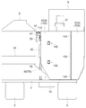
주행 기체에, 운전 좌석을 갖는 운전부와, 상기 운전 좌석의 하방에 위치하여 엔진을 갖는 엔진룸과, 상기 엔진의 배기 가스에 포함되는 질소산화물을 저감하는 배기 가스 정화 장치가 구비되고,An engine room having an engine positioned below the driver's seat and an exhaust gas purifier for reducing nitrogen oxides contained in the exhaust gas of the engine,
상기 배기 가스 정화 장치가 상기 엔진룸 내에 설치되어 있는 점에 있다.And the exhaust gas purifying apparatus is installed in the engine room.
본 발명에 따르면, 배기 가스 정화 장치가 운전 좌석의 하방에 위치하는 엔진룸 내에 설치되어 있기 때문에, 엔진룸 내에는, 엔진과 배기 가스 정화 장치가 구비되게 된다. 따라서, 엔진과 배기 가스 정화 장치를 가깝게 한 상태로 구비할 수 있어, 그것들을 접속하는 배기 가스 통류용 배관이 짧아져, 배관 구조가 간단해진다.According to the present invention, since the exhaust gas purifying apparatus is installed in the engine room located below the driver's seat, the engine and the exhaust gas purifying apparatus are provided in the engine room. Therefore, the engine and the exhaust gas purifier can be provided close to each other, and the piping for exhaust gas communication connecting them is shortened, so that the piping structure is simplified.
본 발명에 있어서는, 상기 배기 가스 정화 장치가 상기 엔진 상에 구비되어 있으면 적합하다.In the present invention, it is preferable that the exhaust gas purifying apparatus is provided on the engine.
본 구성에 의하면, 엔진의 상방 공간을 이용하여, 다른 장치의 배치에 영향을 주는 일없이, 배기 가스 정화 장치를 합리적으로 배치할 수 있다.According to this configuration, the exhaust gas purifying device can be rationally arranged without affecting the arrangement of other devices by utilizing the space above the engine.
본 발명에 있어서는, 상기 배기 가스 정화 장치가 상기 엔진의 상부에 적재 지지되어 있으면 적합하다.In the present invention, it is preferable that the exhaust gas purifier is mounted on the upper portion of the engine.
본 구성에 의하면, 강성이 높은 엔진의 케이싱을 이용하여, 안정한 상태로 배기 가스 정화 장치를 지지할 수 있다.According to this configuration, the exhaust gas purifying apparatus can be supported in a stable state by using the casing of the engine with high rigidity.
본 발명에 있어서는,In the present invention,
상기 엔진이 상기 엔진룸의 전방부 종벽부의 후방에 위치하는 상태로 구비되고,Wherein the engine is provided in a state of being positioned behind a front vertical wall portion of the engine room,
기체 측면에서 보아, 상기 배기 가스 정화 장치의 전단부의 기체 전후 방향에서의 위치가, 상기 엔진의 전단부의 기체 전후 방향에서의 위치와 동일하거나 또는 대략 동일하다면 적합하다.It is preferable that the position of the front end of the exhaust gas purifying device in the forward and backward directions of the gas is the same or substantially the same as the position of the front end of the engine in the forward and backward directions of the gas.
본 구성에 의하면, 배기 가스 정화 장치와 엔진이, 기체 측면에서 보아, 전단부의 기체 전후 방향에서의 위치가 동일하거나 또는 대략 동일하기 때문에, 배기 가스 정화 장치가 엔진보다도 기체 전방부측을 향해 돌출되는 일이 없다.According to this configuration, since the exhaust gas purifying device and the engine have the same or substantially the same position in the front-rear direction of the gas as viewed from the base side, the exhaust gas purifying device is more likely to be projected toward the gas- There is no.
배기 가스 정화 장치가 엔진보다도 전방부측으로 돌출되는 것이면, 엔진룸의 전방부 종벽부의 위치를 변경하는 등의 대폭적인 구조 개량을 필요로 하지만, 본 구성에 의하면, 이러한 구조 개량을 요하지 않고, 엔진룸 내에 있어서의 다른 장치의 배치 구조를 변경하지 않고, 배기 가스 정화 장치를 설치할 수 있다.If the exhaust gas purifying device is projected to the front side of the engine, it is necessary to drastically improve the structure such as changing the position of the front vertical wall of the engine room. However, according to this configuration, The exhaust gas purifying device can be provided without changing the arrangement structure of the other devices in the exhaust gas purifying device.
본 발명에 있어서는,In the present invention,
상기 엔진의 상방에 상기 운전 좌석이 구비되고,The driver's seat is provided above the engine,
상기 운전 좌석의 횡측에 탑승자가 출입하는 승강구가 구비되고,Wherein a driver's seat is provided on a lateral side of the driver's seat,
상기 승강구와는 반대측의 상기 운전 좌석의 횡측에 사이드 패널이 구비되고,A side panel is provided on a lateral side of the driver's seat opposite to the entrance,
상기 배기 가스 정화 장치는, 상기 엔진룸 내 중 상기 사이드 패널의 하방측 개소에, 길이 방향이 기체 전후 방향을 따르는 상태로 구비되어 있으면 적합하다.It is preferable that the exhaust gas purifying apparatus is provided in the engine compartment at a position on the lower side of the side panel in a state where the longitudinal direction is along the gas longitudinal direction.
수확기에 있어서, 운전 좌석에 대하여 승강구와 반대측에 구비되는 사이드 패널은, 각종 조작구가 구비되는 것이며, 운전 좌석에 착좌한 운전자가 팔꿈치를 둘 수 있을 정도로 좌석의 지지대보다도 높은 위치에 설치되고, 또한 전후 방향으로 긴 형상으로 설치되는 경우가 많다.In the harvester, the side panel provided on the opposite side of the driver's seat with respect to the driver's seat is provided with various operation openings, and is provided at a position higher than the support of the seat so that the driver who is seated in the driver's seat can place the elbow, It is often installed in a long shape in the front-rear direction.
그래서, 본 구성에서는, 사이드 패널의 하방측에, 배기 가스 정화 장치를 길이 방향이 기체 전후 방향을 따르는 상태로 구비함으로써, 사이드 패널의 하방측 공간을 유용하게 이용하여 다른 장치의 배치에 영향을 주는 일없이, 배기 가스 정화 장치를 배치할 수 있다.Thus, in this configuration, the exhaust gas purifying device is provided on the lower side of the side panel in the longitudinal direction along the gas longitudinal direction, so that the space on the lower side of the side panel is advantageously utilized, It is possible to dispose the exhaust gas purifying apparatus without any work.
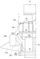
본 발명에 있어서는,In the present invention,
상기 엔진의 배기 가스에 포함되는 입자상 물질을 저감하는 별도의 배기 가스 정화 장치가, 상기 엔진과 상기 배기 가스 정화 장치 사이에 개재 장착되고,A separate exhaust gas purifying apparatus for reducing particulate matter contained in the exhaust gas of the engine is interposed between the engine and the exhaust gas purifying apparatus,
상기 별도의 배기 가스 정화 장치가 상기 엔진룸 내에 설치되어 있으면 적합하다.It is suitable if the separate exhaust gas purifying device is installed in the engine room.
본 구성에 의하면, 엔진룸 내에, 배기 가스에 포함되는 질소산화물을 저감하는 배기 가스 정화 장치와, 배기 가스에 포함되는 입자상 물질을 저감하는 별도의 배기 가스 정화 장치가 각각 구비된다. 엔진의 배기 가스는, 별도의 배기 가스 정화 장치를 통과하여, 입자상 물질이 저감된 후에, 배기 가스 정화 장치를 통과하여 질소산화물이 저감되어, 한층 더 배기 가스가 정화된다.According to this structure, an exhaust gas purifying apparatus for reducing nitrogen oxides contained in the exhaust gas and a separate exhaust gas purifying apparatus for reducing particulate matter contained in the exhaust gas are provided in the engine room, respectively. The exhaust gas of the engine passes through a separate exhaust gas purifying device to reduce the particulate matter, and then passes through the exhaust gas purifying device to reduce nitrogen oxides and further purify the exhaust gas.
배기 가스 정화 장치 및 별도의 배기 가스 정화 장치는, 엔진룸 내에 설치되므로, 엔진에 가깝게 한 상태로 구비할 수 있고, 그것들을 접속하는 배기 가스 통류용 배관이 짧아져, 배관 구조가 간단해진다.Since the exhaust gas purifying device and the separate exhaust gas purifying device are provided in the engine room, the exhaust gas purifying device and the exhaust gas purifying device can be provided close to the engine, and the exhaust gas passing pipe connecting them is shortened.
본 발명에 있어서는, 상기 별도의 배기 가스 정화 장치가, 상기 엔진에 있어서의 라디에이터 냉각팬의 존재측과는 반대측의 측방에 구비되어 있으면 적합하다.In the present invention, it is preferable that the separate exhaust gas purifying apparatus is provided on the side opposite to the side where the radiator cooling fan is present on the engine.
본 구성에 의하면, 라디에이터 냉각팬에 의해 생기된 냉각풍은, 라디에이터 및 엔진의 주위를 통과하고, 또한 별도의 배기 가스 정화 장치의 주위를 통과하여, 외부로 배출된다. 즉, 별도의 배기 가스 정화 장치는 냉각풍의 하류측에 구비된다. 따라서, 배기 가스가 통과함으로써 고온이 되기 쉬운 별도의 배기 가스 정화 장치 주위의 고온의 공기를, 엔진룸 내를 통과시키지 않고, 그대로 외부로 배출할 수 있다.According to this configuration, the cooling wind generated by the radiator cooling fan passes around the radiator and the engine, passes through the circumference of another exhaust gas purification apparatus, and is discharged to the outside. That is, a separate exhaust gas purifier is provided on the downstream side of the cooling wind. Therefore, the high-temperature air around the separate exhaust gas purifying device, which is likely to become hot due to the passage of the exhaust gas, can be discharged to the outside without passing through the engine room.
본 발명에 있어서는, 상기 별도의 배기 가스 정화 장치 중 좌우 방향에서 상기 라디에이터 냉각팬과는 반대측 부분이, 상기 엔진룸 중 좌우 방향에서 상기 라디에이터 냉각팬과는 반대측의 단부로부터 상기 엔진룸의 외측으로 돌출되어 있으면 적합하다.In the present invention, a portion of the separate exhaust gas purifier opposite to the radiator cooling fan in the left-right direction projects from the end of the engine room opposite to the radiator cooling fan in the left-right direction to the outside of the engine room Is appropriate.
배기 가스에 포함되는 입자상 물질을 저감시키기 위해 별도의 배기 가스 정화 장치를 엔진의 근방에 구비할 때, 별도의 배기 가스 정화 장치의 전체를 엔진룸의 내부에 수납하여, 그 주위를, 예를 들어 엔진 보닛 등의 엔진룸을 형성하는 부재에 의해 둘러싸는 것을 생각할 수 있다.When a separate exhaust gas purifier is provided in the vicinity of the engine to reduce the particulate matter contained in the exhaust gas, the entirety of the separate exhaust gas purifier is housed in the engine room, It can be conceived to be surrounded by a member forming an engine room such as an engine bonnet.
그러나, 이와 같은 구성에서는, 배기가 통과함으로써 고온이 되는 별도의 배기 가스 정화 장치의 열이 엔진룸 내에서 가득차게 되어버려, 엔진룸 내의 온도가 상승할 우려가 있다. 엔진룸 내에 대형의 장치인 별도의 배기 가스 정화 장치의 전체를 수납시키면, 엔진룸이 상방으로 돌출되어 운전부의 스페이스가 좁아지는 등, 엔진룸의 주위 영역에 대하여 악영향을 줄 우려도 있다.However, in such a configuration, the heat of the exhaust gas purifying apparatus, which becomes high in temperature due to the passage of the exhaust gas, is filled in the engine room, and the temperature in the engine room may rise. If the whole of the exhaust gas purifying apparatus, which is a large apparatus, is accommodated in the engine room, the engine room may protrude upward to narrow the space of the operating unit, and the adverse effect on the peripheral region of the engine room may be reduced.
이에 비해, 본 구성에 의하면, 별도의 배기 가스 정화 장치가 라디에이터 냉각팬과는 반대측의 단부로부터 엔진룸의 외측으로 돌출되어 있으므로, 별도의 배기 가스 정화 장치 주위의 고온의 공기가 엔진룸 내에서 가득차지 않고 외측으로 배출되기 쉽다. 게다가, 별도의 배기 가스 정화 장치의 전체를, 주위가 구획벽으로 둘러싸진 엔진룸 내에 억지로 수납시킬 필요가 없으므로, 운전부의 스페이스가 좁아지는 등, 주위 영역에 대한 영향을 적게 할 수 있다.On the other hand, according to this configuration, since the separate exhaust gas purifier is protruded to the outside of the engine room from the end opposite to the radiator cooling fan, high temperature air around the exhaust gas purifier is filled in the engine room And is likely to be discharged to the outside. In addition, since it is not necessary to forcibly store the entirety of the separate exhaust gas purifying apparatus in the engine room surrounded by the partition walls, the influence on the peripheral region can be reduced, for example, the space of the operation portion is narrowed.
본 발명에 있어서는, 상기 별도의 배기 가스 정화 장치 중 상기 엔진룸으로부터 외측으로 돌출되어 있는 정화 장치 돌출 부분의 상방, 전방 및 횡측방을 덮는 커버가 구비되어 있으면 적합하다.In the present invention, it is preferable that a cover for covering the upper, front and transverse sides of the purifying device projecting portion protruding outward from the engine room among the separate exhaust gas purifying devices is provided.
본 구성에 의하면, 수확 작업에 따라서 발생하는 짚 부스러기나 미세한 진애 등이, 별도의 배기 가스 정화 장치에 있어서의 정화 장치 돌출 부분에 대하여 상방측 또는 횡측방으로부터 내리덮이거나, 기체의 주행에 수반하여 전방측으로부터 내리덮이거나 하는 것을, 커버에 의해 막음으로써, 진애가 별도의 배기 가스 정화 장치에 내리덮이는 것에 의한 악영향을 피할 수 있다.According to this structure, the straw crumbs and fine dusts generated by the harvesting operation are covered downward from the upper side or the lateral side with respect to the purge device projecting portion in the separate exhaust gas purifying device, or accompanied with the running of the gas It is possible to avoid an adverse effect caused by the fact that the dust is covered with a separate exhaust gas purifying device by covering the inside of the exhaust gas purifying device from the front side with the cover.
본 발명에 있어서는, 상기 커버 중 상기 정화 장치 돌출 부분을 횡측방으로부터 덮는 횡측 커버 부분이 다공 부재로 구성되고, 상기 정화 장치 돌출 부분의 후방이 개방되어 있으면 적합하다.In the present invention, it is preferable that the lateral side cover portion covering the protruding portion of the purifying device from the lateral side of the cover is a porous member, and the rear portion of the purifying device projecting portion is open.
본 구성에 의하면, 별도의 배기 가스 정화 장치 주위의 고온의 공기를, 횡측 커버 부분에 형성된 다수의 구멍으로부터 횡측 외측으로 방출시킬 수 있고, 게다가, 개방되어 있는 정화 장치 돌출 부분의 후방측으로부터도 고온의 공기를 후방 외측으로 방출시킬 수 있다. 그 결과, 별도의 배기 가스 정화 장치의 주위에 있어서 열이 가득차서 온도가 과도하게 상승하는 것을 한층 더 회피하기 쉬워지게 된다. 또한, 커버는, 정화 장치 돌출 부분의 후방이 개방되어 있으므로, 진애가 별도의 배기 가스 정화 장치에 내리덮이는 것을 피할 수 있는 것이면서도, 다수의 구멍으로부터만 방출시키는 것에 비해 열 방출 효과가 높아진다.According to this configuration, it is possible to release the high-temperature air around the separate exhaust gas purifying device from the plurality of holes formed in the transverse cover portion to the lateral side, and furthermore, from the rear side of the open purifying device projecting portion, Air can be released to the rearward outward. As a result, it becomes easier to avoid an excessively rising temperature due to the heat being filled around a separate exhaust gas purifying device. Further, since the rear portion of the purge device projecting portion is open, the dust can be prevented from falling down on the separate exhaust gas purifying device, but the heat release effect is enhanced as compared with the case where the dust is discharged only from a large number of holes .
본 발명에 있어서는, 상기 별도의 배기 가스 정화 장치는 상기 엔진에 지지되어 있으면 적합하다.In the present invention, the separate exhaust gas purifying apparatus is suitable if it is supported by the engine.
본 구성에 의하면, 강성이 높은 엔진의 케이싱을 이용하여, 안정한 상태로 별도의 배기 가스 정화 장치를 지지할 수 있다.According to this configuration, it is possible to support a separate exhaust gas purifying apparatus in a stable state by using the casing of the engine with high rigidity.
본 발명에 있어서는,In the present invention,
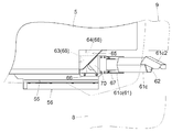
상기 별도의 배기 가스 정화 장치는, 상기 엔진의 상부에 대응하는 위치에 구비되고,Wherein the separate exhaust gas purifier is provided at a position corresponding to an upper portion of the engine,
상기 배기 가스 정화 장치는, 상기 별도의 배기 가스 정화 장치로부터 배출된 배기 가스와 요소수를 혼합시키는 배기 중계부와, 상기 배기 중계부로부터 배출된 배기 가스를 환원 처리하는 장치 본체부를 구비하고,The exhaust gas purifying apparatus includes an exhaust repeater for mixing exhaust gas and urea water discharged from the separate exhaust gas purifier and an apparatus main body for reducing the exhaust gas discharged from the exhaust gas relay,
상기 장치 본체부는, 상기 엔진의 상측에 있어서, 상기 엔진에 대하여 상기 라디에이터 냉각팬의 존재측과는 반대측에 위치하는 상태로 구비되고,The apparatus main body portion is provided on the upper side of the engine in a state of being positioned opposite to the side where the radiator cooling fan is present with respect to the engine,
상기 배기 중계부가, 상기 별도의 배기 가스 정화 장치의 상측이며 또한 상기 장치 본체부에 대하여 상기 라디에이터 냉각팬의 존재측과는 반대측에 위치하는 상태로 구비되어 있으면 적합하다.It is preferable that the exhaust repeater is provided on the upper side of the separate exhaust gas purifier and on the side opposite to the side where the radiator cooling fan is present with respect to the apparatus main body.
본 구성에 의하면, 별도의 배기 가스 정화 장치는, 엔진의 상부에 대응하는 위치에 구비되기 때문에, 엔진의 상방 공간을 이용하여, 다른 장치의 배치에 영향을 주는 일없이, 별도의 배기 가스 정화 장치를 합리적으로 배치할 수 있다. 또한, 배기 가스 정화 장치는 라디에이터 냉각팬의 존재측과는 반대측의 측방에 위치하고 있으며, 그 중 장치 본체부는 엔진의 상측에 위치하고, 배기 중계부는 별도의 배기 가스 정화 장치의 상측에 위치하고 있다.According to this configuration, since the separate exhaust gas purifying apparatus is provided at the position corresponding to the upper portion of the engine, it is possible to use the space above the engine, without affecting the arrangement of other apparatuses, Can be reasonably arranged. Further, the exhaust gas purifying apparatus is located on the side opposite to the side where the radiator cooling fan is present, of which the apparatus main body is located on the upper side of the engine, and the exhaust gas relay is located on the upper side of the other exhaust gas purifying apparatus.
따라서, 배기 가스 정화 장치는, 라디에이터 냉각팬에 의한 냉각풍의 하류측에 구비되고, 고온이 되기 쉬운 배기 가스 정화 장치 주위의 고온의 공기를, 엔진룸 내를 통과시키지 않고, 그대로 외부로 배출할 수 있다. 또한, 배기 가스 정화 장치와 별도의 배기 가스 정화 장치를, 엔진의 상부에 콤팩트하게 배치할 수 있다.Therefore, the exhaust gas purifying apparatus is capable of discharging hot air around the exhaust gas purifying apparatus, which is provided on the downstream side of the cooling wind by the radiator cooling fan, which is prone to high temperature, to the outside without passing through the engine room have. Further, the exhaust gas purifying device and the exhaust gas purifying device separate from each other can be arranged compactly on the top of the engine.
본 발명에 있어서는, 상기 배기 중계부 중 좌우 방향에서 상기 라디에이터 냉각팬과는 반대측 부분이, 상기 엔진룸 중 좌우 방향에서 상기 라디에이터 냉각팬과는 반대측의 단부로부터 상기 엔진룸의 외측으로 돌출되어 있으면 적합하다.In the present invention, it is preferable that a portion of the exhaust gas relay portion opposite to the radiator cooling fan in the left-right direction protrudes from the end portion of the engine room on the opposite side of the radiator cooling fan from the left- Do.
본 구성에 의하면, 상기한 바와 같은 별도의 배기 가스 정화 장치의 경우와 동일하게, 배기 중계부가 라디에이터 냉각팬과는 반대측의 단부로부터 엔진룸의 외측으로 돌출되어 있으므로, 배기 중계부 주위의 고온의 공기가 엔진룸 내에서 가득차지 않고 외측으로 배출되기 쉽다. 게다가, 배기 중계부 전체를, 주위가 구획벽으로 둘러싸진 엔진룸 내에 억지로 수납시킬 필요가 없으므로, 운전부의 스페이스가 좁아지는 등, 주위 영역에 대한 영향을 적게 할 수 있다.According to this configuration, as in the case of the separate exhaust gas purifying apparatus as described above, since the exhaust repeating portion protrudes outside the engine room from the end opposite to the radiator cooling fan, the high temperature air around the exhaust repeating portion Is likely to be exhausted to the outside without filling up in the engine room. In addition, since it is not necessary to forcibly store the entire exhaust gas recirculation unit in the engine room surrounded by the partition wall, the influence on the surrounding region can be reduced, for example, the space of the operation unit is reduced.
본 발명에 있어서는, 상기 배기 중계부 중 상기 엔진룸으로부터 외측으로 돌출되어 있는 중계부 돌출 부분의 상방, 전방 및 횡측방을 덮는 커버가 구비되어 있으면 적합하다.In the present invention, it is preferable that a cover that covers the upper portion, the front portion, and the lateral portion of the projecting portion of the relay portion protruding outward from the engine room out of the exhaust repeater portions is provided.
본 구성에 의하면, 수확 작업에 따라서 발생하는 짚 부스러기나 미세한 진애 등이, 배기 중계부에 있어서의 중계부 돌출 부분에 대하여 상방측 또는 횡측방으로부터 내리덮이거나, 기체의 주행에 수반하여 전방측으로부터 내리덮이거나 하는 것을, 커버에 의해 막음으로써, 진애가 배기 중계부에 내리덮이는 것에 의한 악영향을 피할 수 있다.According to this configuration, the straw crumbs and fine dusts generated by the harvesting operation are covered downward from the upper side or the transverse side with respect to the projecting portion of the relay portion in the exhaust relay portion, It is possible to avoid an adverse effect caused by the fact that the dust is covered with the exhaust gas relay portion by covering the dust cover with the cover.
본 발명에 있어서는, 상기 커버 중 상기 중계부 돌출 부분의 횡측방을 덮는 횡측 커버 부분이 다공 부재로 구성되고, 상기 중계부 돌출 부분의 후방이 개방되어 있으면 적합하다.In the present invention, it is preferable that the lateral side cover portion covering the transverse side of the relay projecting portion is made of a porous member and the rear portion of the relay projecting portion is opened.
본 구성에 의하면, 배기 중계부 주위의 고온의 공기를, 횡측 커버 부분에 형성된 다수의 구멍으로부터 횡측 외측으로 방출시킬 수 있고, 게다가, 개방되어 있는 중계부 돌출 부분의 후방측으로부터도 고온의 공기를 후방 외측으로 방출시킬 수 있다. 그 결과, 배기 중계부 주위에 있어서 열이 가득차서 온도가 과도하게 상승하는 것을 한층 더 회피하기 쉬운 것이 된다. 또한, 커버는, 중계부 돌출 부분의 후방이 개방되어 있으므로, 진애가 배기 중계부에 내리덮이는 것을 피할 수 있는 것이면서도, 다수의 구멍으로부터만 방출시키는 것에 비해 열 방출 효과가 높아진다.According to this configuration, it is possible to discharge the high-temperature air around the exhaust relay portion from the plurality of holes formed in the transverse cover portion to the lateral side, and furthermore, the hot air from the rear side of the opening portion of the relay portion And can be discharged to the rearward outside. As a result, the temperature rises excessively around the exhaust repeating portion due to the heat being filled. Further, since the rear portion of the relay projected portion is open, the dust can be prevented from falling down on the exhaust relay portion, but the heat release effect is enhanced as compared with the case where the dust is discharged only from a large number of holes.
본 발명에 있어서는, 상기 별도의 배기 가스 정화 장치는 상기 배기 중계부의 하방에 구비되고,In the present invention, the separate exhaust gas purifier may be provided below the exhaust gas relay,
상기 별도의 배기 가스 정화 장치 중 좌우 방향에서 상기 라디에이터 냉각팬과는 반대측 부분이, 상기 엔진룸 중 좌우 방향에서 상기 라디에이터 냉각팬과는 반대측의 단부로부터 상기 엔진룸의 외측으로 돌출되고,A portion of the separate exhaust gas purifying device opposite to the radiator cooling fan in a lateral direction is protruded from the end portion of the engine room opposite to the radiator cooling fan in a lateral direction of the engine room to the outside of the engine room,
상기 배기 중계부 중 좌우 방향에서 상기 라디에이터 냉각팬과는 반대측 부분이, 상기 엔진룸 중 좌우 방향에서 상기 라디에이터 냉각팬과는 반대측의 단부로부터 상기 엔진룸의 외측으로 돌출되어 있으면 적합하다.It is preferable that a portion of the exhaust gas relay portion opposite to the radiator cooling fan in the lateral direction protrudes from the end portion of the engine room opposite to the radiator cooling fan to the outside of the engine room.
본 구성에 의하면, 별도의 배기 가스 정화 장치 및 배기 중계부 각각이 엔진룸의 외측으로 돌출되어 있으므로, 별도의 배기 가스 정화 장치 및 배기 중계부 주위의 고온의 공기가 엔진룸 내에서 가득차지 않고 외측으로 배출되기 쉽다. 게다가, 별도의 배기 가스 정화 장치 및 배기 중계부 전체를, 주위가 구획벽으로 둘러싸진 엔진룸 내에 억지로 수납시킬 필요가 없으므로, 운전부의 스페이스가 좁아지는 등, 주위 영역에 대한 영향을 적게 할 수 있다.According to this configuration, since each of the separate exhaust gas purifying device and the exhaust relaying portion protrudes to the outside of the engine room, the high temperature air around the exhaust gas purifying device and the exhaust relay portion does not fill up in the engine room, . In addition, since it is not necessary to forcibly store the entire exhaust gas purifying device and the exhaust gas recirculation part in the engine room surrounded by the partition wall, the influence on the surrounding area can be reduced, for example, the space of the operation part is narrowed .
본 발명에 있어서는, 상기 별도의 배기 가스 정화 장치 중 상기 엔진룸으로부터 외측으로 돌출되어 있는 정화 장치 돌출 부분, 및 상기 배기 중계부 중 상기 엔진룸으로부터 외측으로 돌출되어 있는 중계부 돌출 부분의 상방, 전방 및 횡측방을 덮는 커버가 구비되어 있으면 적합하다.In the present invention, the purge device projecting portion protruding outward from the engine room of the separate exhaust gas purifying device, and the upper portion and the front portion of the projecting portion of the relay portion protruding outward from the engine room, And a cover for covering the lateral side are provided.
본 구성에 의하면, 수확 작업에 따라서 발생하는 짚 부스러기나 미세한 진애 등이, 별도의 배기 가스 정화 장치에 있어서의 정화 장치 돌출 부분, 및 배기 중계부에 있어서의 중계부 돌출 부분에 대하여 상방측 또는 횡측방으로부터 내리덮이거나, 기체의 주행에 수반하여 전방측으로부터 내리덮이거나 하는 것을, 커버에 의해 덮음으로써, 진애가 별도의 배기 가스 정화 장치나 배기 중계부에 내리덮이는 것에 의한 악영향을 피할 수 있다.According to this configuration, the straw crumbs and fine dusts generated in accordance with the harvesting operation can be prevented from reaching the purge device projecting portions of the exhaust gas purifying apparatus and the relay projecting portions of the exhaust gas relaying portion, It is possible to avoid the adverse effect caused by the covering of the dust and dirt on the separate exhaust gas purifying device or the exhaust gas repeating portion by covering the under cover from the side or covering the cover from the front side with the running of the gas have.
본 발명에 있어서는, 상기 커버 중 상기 정화 장치 돌출 부분 및 상기 중계부 돌출 부분의 횡측방을 덮는 횡측 커버 부분이 다공 부재로 구성되고,In the present invention, the side cover portion covering the lateral sides of the purge device projecting portion and the relay projecting portion of the cover is constituted by a porous member,
상기 정화 장치 돌출 부분 및 상기 중계부 돌출 부분의 후방이 개방되어 있으면 적합하다.It is suitable that the purifier projection and the rear portion of the projection project from the relay are open.
본 구성에 의하면, 별도의 배기 가스 정화 장치 및 배기 중계부 주위의 고온의 공기를, 횡측 커버 부분에 형성된 다수의 구멍으로부터 횡측 외측으로 방출시킬 수 있고, 게다가, 개방되어 있는 정화 장치 돌출 부분 및 중계부 돌출 부분의 후방측으로부터도 고온의 공기를 후방 외측으로 방출시킬 수 있다. 그 결과, 별도의 배기 가스 정화 장치 및 배기 중계부 주위에 있어서 열이 가득차서 온도가 과도하게 상승하는 것을 한층 더 회피하기 쉬운 것이 된다. 커버는, 정화 장치 돌출 부분 및 중계부 돌출 부분의 후방이 개방되어 있으므로, 진애가 별도의 배기 가스 정화 장치 및 배기 중계부에 내리덮이는 것을 피할 수 있는 것이면서도, 다수의 구멍으로부터만 방출시키는 것에 비해 열 방출 효과가 높아진다.According to this configuration, it is possible to discharge the high-temperature air around the exhaust gas purifying device and the exhaust relay section from the plurality of holes formed in the side cover portion to the lateral side, and further, The high-temperature air can be released from the rear side of the sub-projecting portion to the rearward outward side. As a result, it is easy to avoid excessive rise of temperature around the exhaust gas purifying device and the exhaust gas relay portion due to the heat being filled. Since the cover is open to the rear of the purge device projecting portion and the projecting portion of the relay portion, the dust can be prevented from falling down on the separate exhaust gas purifying device and the exhaust gas relay portion, The effect of heat emission is enhanced.
본 발명에 있어서는, 상기 커버는, 상기 중계부 돌출 부분의 상방 및 횡측방을 덮는 제1 커버부와, 상기 정화 장치 돌출 부분의 횡측방을 덮는 제2 커버부를 구비하고,In the present invention, it is preferable that the cover includes a first cover portion which covers the upper side and the lateral side of the relay projecting portion, and a second cover portion which covers the transverse side of the purifier projecting portion,
상기 정화 장치 돌출 부분이 상기 중계부 돌출 부분보다도 외측으로 돌출되어 있으며,The purge device projecting portion protrudes outward beyond the relay projecting portion,
상기 제2 커버부가 상기 제1 커버부보다도 외측으로 돌출되어 좌우 방향으로 단차를 형성하는 상태에서, 상기 제1 커버부와 상기 제2 커버부가 상하로 나열되는 상태로 구비되어 있으면 적합하다.It is preferable that the first cover portion and the second cover portion are provided in a state in which the first cover portion and the second cover portion are arranged vertically in a state in which the second cover portion protrudes outward from the first cover portion to form a step in the left and right direction.
일반적으로 배기 중계부보다도 대형이 되는 경향이 있는 별도의 배기 가스 정화 장치를, 배기 중계부보다도 외측으로 돌출시키고 있으므로, 별도의 배기 가스 정화 장치 및 배기 중계부 전체를, 주위가 구획벽으로 둘러싸인 엔진룸 내에 무리하게 수납시킬 필요가 없으므로, 운전부의 스페이스가 좁아지는 등, 주위 영역에 대한 영향을 적게 할 수 있다.A separate exhaust gas purifying device, which generally tends to become larger than the exhaust relay portion, is projected outwardly from the exhaust relay portion. Therefore, the entirety of the exhaust gas purifying device and the exhaust gas relay portion can be replaced by an engine It is not necessary to accommodate them in a room excessively, so that the influence on the peripheral region can be reduced, for example, the space of the operation portion is narrowed.
또한, 커버로서, 중계부 돌출 부분을 덮는 제1 커버부와, 정화 장치 돌출 부분을 덮는 제2 커버부를 상하로 나열되는 상태로 구비하는 구성으로 하고, 제2 커버부가 제1 커버부보다도 외측으로 돌출되어, 제2 커버부와 제1 커버부 사이에 좌우 방향으로 단차가 형성되어 있다.The cover may have a structure in which the first cover portion covering the projecting portion of the relay portion and the second cover portion covering the purge device projecting portion are arranged vertically and the second cover portion is arranged outward And a step is formed between the second cover portion and the first cover portion in the lateral direction.
이렇게 구성함으로써, 제1 커버부를 배기 중계부에 근접시킴과 함께, 제2 커버부를 별도의 배기 가스 정화 장치에 근접시켜, 커버가 불필요하게 튀어나오는 일이 없고, 단차의 상방측에 형성된 외측 공간을 배선이나 배관 등의 통과 영역으로서 유용하게 이용할 수도 있다. 또한, 제1 커버부와 제2 커버부로 분할 형성됨으로써, 청소 등의 메인터넌스 작업 등에서는, 커버 전체를 떼어내지 않고, 필요한 개소만 떼어내어 쉽게 작업을 행할 수 있다.With this configuration, the first cover portion is brought close to the exhaust gas relay portion, and the second cover portion is brought close to the other exhaust gas purifier so that the cover does not unnecessarily protrude, and the outer space formed above the step It can also be usefully used as a passage region for wiring and piping. Further, by forming the first cover portion and the second cover portion in a divided manner, the maintenance can be easily performed by removing only the necessary portions without removing the entire cover.
본 발명에 있어서는,In the present invention,
상기 별도의 배기 가스 정화 장치는, 전방부측에 상기 엔진으로부터의 배기를 받아들이는 배기 입구부를 구비함과 함께, 후방부측에 정화 처리 후의 배기 가스를 배출하는 배기 출구부를 구비하고,The separate exhaust gas purifying apparatus includes an exhaust inlet portion for receiving exhaust from the engine on the front side and an exhaust outlet portion for exhausting the exhaust gas after the purification treatment on the rear side,
상기 배기 가스 정화 장치는, 전방부측에 상기 별도의 배기 가스 정화 장치로부터 상기 배기 중계부를 통해 공급되는 배기 가스를 받아들이는 배기 입구부를 구비함과 함께, 후방부측에 정화 처리 후의 배기 가스를 배출하는 배기 출구부를 구비하고 있으면 적합하다.The exhaust gas purifying apparatus includes an exhaust inlet portion for receiving the exhaust gas supplied from the separate exhaust gas purifying device through the exhaust relay portion in the front side portion and an exhaust inlet portion for receiving the exhaust gas after the purifying process, It is suitable if it has an outlet.
본 구성에 의하면, 별도의 배기 가스 정화 장치는, 엔진으로부터 배출된 배기 가스를 전방부측의 배기 입구부로부터 받아들여, 기체 후방측으로 유동시키면서 입자상 물질의 저감 처리를 실행한 후에 후방부측의 배기 출구부로부터 배출시키도록, 장치 내부에 배기 유동 경로가 형성된다.According to this configuration, the separate exhaust gas purifying apparatus is configured such that the exhaust gas discharged from the engine is taken in from the exhaust inlet portion on the front side and flows to the rear side of the gas so as to perform the particulate matter reduction treatment, An exhaust flow path is formed inside the apparatus.
배기 가스 정화 장치는, 별도의 배기 가스 정화 장치로부터 배출된 배기 가스를, 배기 중계부를 통해 요소수와 혼합시키면서 기체 전방측으로 유동시킨 후 장치 본체에 공급하고, 장치 본체내를 기체 후방측으로 유동시킨 후 배기 출구부로부터 배출시키도록 배기 유동 경로가 형성된다.The exhaust gas purifying apparatus is characterized in that exhaust gas discharged from a separate exhaust gas purifying apparatus is mixed with urea water through an exhaust gas relay unit to flow to the front side of the gas and then supplied to the main body of the apparatus, An exhaust flow path is formed so as to be discharged from the exhaust outlet portion.
배기 가스 정화 장치와 별도의 배기 가스 정화 장치를 엔진의 상부에 콤팩트하게 배치하면서, 배기 유동 경로가 가능한 한 짧아지도록 합리적으로 배기를 유동시킬 수 있다.The exhaust gas purifying device and the exhaust gas purifying device separate from each other can be compactly arranged on the top of the engine and the exhaust flow can be reasonably flowed so that the exhaust flow path becomes as short as possible.
본 발명에 있어서는,In the present invention,
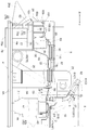
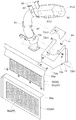
수확한 작물을 탈곡 처리하는 탈곡 장치가 구비되고,A threshing device for threshing the harvested crop is provided,
상기 운전부의 후방부와 상기 탈곡 장치의 전방부가 기체 측면에서 보아 중복되는 상태에서, 상기 운전부가 상기 주행 기체의 좌우 방향 일방측에 설치됨과 함께, 상기 탈곡 장치가 상기 주행 기체의 좌우 방향 타방측에 설치되고,Wherein the driving part is provided on one side in the left and right direction of the traveling body in a state in which the rear part of the driving part and the front part of the traveling device overlap each other as viewed from the side of the base, Installed,
상기 배기 가스 정화 장치의 기체 후방부측 개소에, 정화 처리된 배기 가스를 외측으로 방출하는 배기관이 접속되고,An exhaust pipe for discharging the purified exhaust gas to the outside is connected to a position on the rear side of the exhaust gas purifying device,
상기 배기관은, 상기 운전부의 후방부와 상기 탈곡 장치의 전방부 사이에 있어서 상방으로 연장되어 있으면 적합하다.It is preferable that the exhaust pipe extends upward between the rear portion of the operation portion and the front portion of the threshing device.
본 구성에 의하면, 운전부의 후방부와 탈곡 장치의 전방부 사이의 공간을 이용하여, 다른 장치의 배치에 제약을 주는 일없이, 배기관을 구비할 수 있다. 배기관은 배기 가스를 기체 상방측으로부터 배출하므로, 배기 가스를 외측으로 방산시키기 쉽다.According to this configuration, the space between the rear portion of the operation portion and the front portion of the threshing device can be used, and the exhaust pipe can be provided without restricting the arrangement of the other devices. Since the exhaust pipe discharges the exhaust gas from above the gas, it is easy to dissipate the exhaust gas to the outside.
본 발명에 있어서는,In the present invention,
상기 탈곡 장치와 횡 나열 상태로 곡립 탱크가 구비되고,A graining tank is provided in a transversely aligned state with the threshing device,
상기 곡립 탱크의 기체 전방부측에서 또한 상기 탈곡 장치측의 횡측 개소에, 상기 탈곡 장치로부터 배출된 곡립을 상기 곡립 탱크로 반송하는 양곡 장치가 구비되고,A grazing device for conveying the grains discharged from the threshing device to the graining tank is provided at a gas front side of the graining tank and at a lateral position of the threshing device side,
상기 배기관은, 상기 양곡 장치의 전방부측에 있어서 상기 양곡 장치의 상방까지 연장 설치됨과 함께, 상단부에 배기구가 형성되고,Wherein the exhaust pipe is provided so as to extend to the upper side of the gravity device on the front side of the grazing device and has an exhaust port formed in the upper end thereof,
상기 배기구는, 상기 양곡 장치의 상방에 있어서 상기 탈곡 장치측을 향해 개구되어 있으면 적합하다.It is preferable that the exhaust port is opened toward the threshing device side above the grazing device.
본 구성에 의하면, 배기관은 양곡 장치의 상방까지 연장 설치되고, 게다가, 상단부의 배기구는 탈곡 장치측을 향해 개구되어 있으므로, 배기구로부터 배출되는 배기 가스가, 내부에 곡립이 존재하고 있는 곡립 탱크나 양곡 장치에 직접 내리덮이는 일이 없고, 곡립에 악영향을 줄 우려가 적다.According to this configuration, since the exhaust pipe is extended to the upper side of the grazing machine and the exhaust port at the upper end opens toward the threshing device, the exhaust gas discharged from the exhaust port is discharged to the outside of the grappling tank, There is no possibility of falling down directly on the apparatus, and there is little possibility of adversely affecting the grain.
본 발명에 있어서는,In the present invention,
상기 주행 기체 전체를 지지하는 기체 프레임과, 상기 기체 프레임으로부터 기립 설치되며 또한 상기 운전부의 후방부측을 지지하는 종(縱)프레임이 구비되고,A base frame for supporting the entire traveling body, and a vertical frame which stands up from the base frame and supports the rear side of the operation section,
상기 종프레임에, 상기 배기 가스 정화 장치의 보조 기기가 지지되어 있으면 적합하다.It is preferable that the auxiliary frame of the exhaust gas purifying device is supported on the longitudinal frame.
본 구성에 의하면, 운전부를 지지하기 위해 구비된 종프레임을 이용하여 배기 가스 정화 장치의 보조 기기를 지지함으로써, 예를 들어 보조 기기는, 엔진 또는 그것과 일체적으로 설치되는 장치에 지지되는 경우에 비해, 진동이 적은 상태에서 안정된 동작을 행하게 할 수 있다.According to this structure, by supporting the auxiliary equipment of the exhaust gas purification apparatus by using the longitudinal frame provided for supporting the operation unit, for example, when the auxiliary equipment is supported by the engine or an apparatus integrally provided with the engine It is possible to perform a stable operation in a state where the vibration is small.
본 발명에 있어서는, 상기 엔진룸을 구획 형성하는 엔진 보닛이 구비되고,In the present invention, an engine bonnet for partitioning the engine room is provided,
상기 엔진 보닛에 있어서의 상부측 부분 중 상기 엔진의 상측에 위치하는 개소에 상기 운전 좌석이 지지되고,Wherein the driver's seat is supported on a portion of the upper portion of the engine bonnet which is located on the upper side of the engine,
상기 엔진 보닛에 있어서의 상부측 부분 중 상기 운전 좌석의 횡측에 위치하는 개소에 상방으로 돌출되는 돌출부가 형성되고,A protruding portion protruding upward is formed at a portion of the upper portion of the engine bonnet which is located on the lateral side of the driver's seat,
상기 엔진룸 중 상기 돌출부에 대응하는 돌출부 형성 영역에 상기 배기 가스 정화 장치가 배치되어 있으면 적합하다.It is preferable that the exhaust gas purifying device is arranged in a protruding portion forming region corresponding to the protruding portion of the engine room.
본 구성에 의하면, 운전 좌석을 피한 위치에서, 또한 비교적 스페이스에 여유가 있는 개소를 이용하여, 배기 가스 정화 장치를 콤팩트하게 배치할 수 있다.According to this configuration, the exhaust gas purifying apparatus can be compactly arranged at a position where the driver's seat is avoided and at a portion having a margin in a relatively space.
(2) 과제 2에 대응하는 해결 수단은 이하와 같다.(2) The solution to the
본 발명에 따른 수확기의 특징 구성은, 주행 기체에, 엔진과, 운전 좌석을 갖는 운전부와, 상기 운전 좌석의 하방에 위치하여 상기 엔진의 배기 가스를 정화 처리하는 배기 가스 처리 장치와, 상기 배기 가스 처리 장치에서 처리된 배기 가스를 외측으로 방출하는 배기관이 구비되고, 상기 배기관이, 상기 운전 좌석보다도 후방측에 있어서 상향으로 연장되어 있는 점에 있다.A characteristic feature of the harvester according to the present invention is that the driving machine includes an engine, an operation unit having a driver's seat, an exhaust gas processing device disposed below the driver's seat for purifying the exhaust gas of the engine, There is provided an exhaust pipe for exhausting the exhaust gas processed by the gas treatment device to the outside, and the exhaust pipe extends upwardly on the rear side of the driver's seat.
본 발명에 따르면, 배기관이 상향으로 연장되어 있으므로, 엔진으로부터의 배기가 상방측으로 유도되어, 주행 기체의 높은 위치로부터 외측으로 방출되게 된다. 이렇게 높은 위치에서 방출됨으로써, 대기 중에 신속히 확산시킬 수 있다. 그리고, 배기관은 운전 좌석보다도 후방측에 있어서 상향으로 연장되므로, 운전 좌석에 착좌하고 있는 운전자의 시계가 상향으로 연장되는 배기관에 의해 차단되어 운전 조작에 악영향을 줄 우려가 적다. 게다가, 배기관에, 포장의 이토가 걸리거나 하여 배기관의 열화가 촉진되거나 할 우려도 없다.According to the present invention, since the exhaust pipe extends upward, the exhaust gas from the engine is directed upward and discharged outward from the high position of the traveling gas. By being emitted at such a high position, it can be rapidly diffused into the atmosphere. Further, since the exhaust pipe extends upwardly on the rear side of the driver's seat, the driver's watch sitting on the driver's seat is blocked by the exhaust pipe extending upward, and there is little possibility of adverse effect on the driving operation. In addition, there is no possibility that the exhaust pipe is caught in the exhaust pipe, thereby accelerating deterioration of the exhaust pipe.
따라서, 운전 조작에 악영향을 주는 일없이, 배기관의 내구성을 향상시키면서, 엔진으로부터의 배기 가스를 대기 중으로 확산시키기 쉽게 하는 것이 가능해졌다.Therefore, it becomes possible to easily diffuse the exhaust gas from the engine into the atmosphere, while improving the durability of the exhaust pipe without adversely affecting the driving operation.
본 발명에 있어서는, 상기 주행 기체에, 수확한 작물을 탈곡 처리하는 탈곡 장치와, 곡립을 저류하는 곡립 탱크가, 좌우 방향으로 나열되는 상태로 구비되고, 상기 배기관이, 상기 운전부의 후방부 개소와, 상기 탈곡 장치의 전방부에 있어서의 좌우 방향 중앙측 개소와, 상기 곡립 탱크의 전방부에 있어서의 좌우 방향 중앙측 개소에 의해 둘러싸인 공간을 상향으로 연장되고, 또한 상기 운전부의 후방부에 지지되어 있으면 적합하다.In the present invention, the running vehicle is provided with a threshing device for threshing the harvested crop and a grape tanks for storing the grains are arranged in the left-right direction, and the exhaust pipe is connected to the rear portion of the driving portion , A space surrounded by a central side portion in the left and right direction in the front portion of the threshing device and a central side portion in the right and left direction in the front portion of the curling tank extends upward and is supported at the rear portion of the operation portion If you are fit.
본 구성에 의하면, 운전부, 탈곡 장치 및 곡립 탱크에 의해 둘러싸인 공간을 유효하게 이용하여, 다른 장치에 방해되는 일이 없는 상태에서, 배기관을 배치할 수 있다. 배기관 주위가 탈곡 장치, 곡립 탱크, 운전부라는 대형의 장치에 의해 둘러싸여 있으므로, 기체 외측으로부터 작업자가 잘못해서 배기관에 접촉할 우려가 없다.According to this configuration, the space surrounded by the operation portion, the threshing device, and the grainy tank can be effectively used, and the exhaust pipe can be disposed in a state in which the other device is not disturbed. Since the exhaust pipe is surrounded by a large apparatus such as a threshing device, a graining tank, and a driving unit, there is no fear that an operator accidentally touches the exhaust pipe from the outside of the base.
그리고, 배기관이 운전부의 후방부에 지지되므로, 기체의 진동에 의해 지지 상태가 불안정해질 우려가 적다. 이와 같은 구성 대신에, 예를 들어 배기관을 탈곡 장치에 지지하는 구성을 생각할 수 있다. 그러나, 탈곡 장치는 급동의 회전에 따라서 진동이 발생하지만, 탈곡 장치와 엔진에 연계되는 배기관은 진동의 주기에 차이가 있다. 그 결과, 배기관을 탈곡 장치에 지지하는 구성에서는, 진동 주기의 차이에서 기인하여, 장기간 사용에 따라서 배기관을 지지하는 개소가 파손되는 등, 배기관의 지지 상태가 불안정해질 우려가 있다. 이에 비해, 배기관이 운전부의 후방부에 지지되는 구성에서는, 운전부에는 특별한 진동원은 없고, 엔진의 진동과 대략 동일한 주기의 진동이 되므로, 상기한 바와 같은 불리함이 없어 양호한 지지 상태를 유지하기 쉽다.Further, since the exhaust pipe is supported on the rear portion of the operation portion, there is little possibility that the support state becomes unstable due to vibration of the base body. Instead of such a configuration, for example, a configuration in which the exhaust pipe is supported by the threshing device can be considered. However, in the threshing device, vibration occurs in accordance with the rotation of the swash plate, but the cycle of vibration differs between the threshing device and the exhaust pipe connected to the engine. As a result, in a configuration in which the exhaust pipe is supported on the threshing device, there is a possibility that the support state of the exhaust pipe becomes unstable due to a difference in the oscillation period, such that a portion supporting the exhaust pipe is broken due to use for a long period of time. On the other hand, in the configuration in which the exhaust pipe is supported on the rear portion of the operation portion, there is no special vibration source in the operation portion, and vibration of approximately the same cycle as the vibration of the engine is obtained. easy.
본 발명에 있어서는, 상기 운전부에, 상기 운전 좌석의 상방 공간을 덮는 캐빈이 구비되고,In the present invention, the operation section is provided with a cabin which covers the upper space of the driver's seat,
상기 배기관의 상부가 상기 캐빈의 후방부에 지지되어 있으면 적합하다.It is suitable if the upper portion of the exhaust pipe is supported on the rear portion of the cabin.
캐빈은, 운전 좌석의 상방 공간을 덮기 위해 대형이면서 또한 견고하게 설치된다. 본 구성에 의하면, 배기관이 이러한 캐빈에 지지되므로, 배기관을 안정된 상태로 지지하기 쉽다. 또한, 상향으로 연장되어 외팔보 형상으로 되어 있는 배기관의 상부가 캐빈의 후방부에 지지되므로, 배기관을 덜걱거림이 없는 안정한 상태로 지지할 수 있다.The cabin is large and rigidly installed to cover the upper space of the driver's seat. According to this configuration, since the exhaust pipe is supported by such a cabin, it is easy to support the exhaust pipe in a stable state. Further, since the upper portion of the exhaust pipe extending upward and cantilevered is supported on the rear portion of the cabin, the exhaust pipe can be supported in a stable state without rattling.
본 발명에 있어서는, 상기 배기관은, 하부측 개소 및 상부측 개소 각각에 굴곡부가 형성되고, 또한 상기 하부측 개소 및 상기 상부측 개소 각각이 상기 캐빈의 후방부에 지지되어 있으면 적합하다.In the present invention, it is preferable that the exhaust pipe is provided with a bent portion on each of the lower side portion and the upper side portion, and each of the lower side portion and the upper side portion is supported on the rear portion of the cabin.
배기관에 있어서의 굴곡부가 형성되는 개소는, 직선상으로 길게 연장되는 직관 부분에 비해 강도가 높게 설정되는 경우가 많다. 그래서, 본 구성에 의하면, 상하 양측에 위치하는 강도가 높은 개소를 캐빈에 지지하므로, 안정된 상태에서 배기관을 지지할 수 있다.The portion where the bent portion is formed in the exhaust pipe is often set to have a higher strength than the straight portion extending straightly. Therefore, according to this structure, the exhaust pipe can be supported in a stable state by supporting the cabin with high strength portions located on both the upper and lower sides.
본 발명에 있어서는, 상기 배기관의 하측 부분을 덮는 하부 커버가 구비되고,In the present invention, a lower cover is provided to cover a lower portion of the exhaust pipe,
상기 하부 커버는, 상기 배기관의 주위를 둘러싸는 종벽부와, 상기 종벽부의 상부와 상기 배기관의 외주의 간극을 막는 상측 덮개부를 구비하고 있으면 적합하다.It is preferable that the lower cover includes a vertical wall surrounding the periphery of the exhaust pipe and an upper lid covering the gap between the upper portion of the vertical wall and the outer periphery of the exhaust pipe.
본 구성에 의하면, 하부 커버에 있어서의 종벽부에 의해 배기관의 하부 주위를 덮을 뿐만 아니라, 상측 덮개부에 의해, 종벽부의 상부와 배기관의 외주의 간극을 막도록 했기 때문에, 배기관의 주위 공간을 통해, 하방에 위치하는 고온의 배기 가스 정화 장치를 향해, 배출 짚 부스러기나 작업에 따른 진애 등이 내리덮이는 것을 방지할 수 있다.According to this configuration, not only the bottom portion of the exhaust pipe is covered by the vertical wall portion of the lower cover but also the gap between the upper portion of the vertical wall portion and the outer periphery of the exhaust pipe is blocked by the upper lid portion, , It is possible to prevent the discharged straw crumbs and the dust and the like caused by the operation from falling down toward the high-temperature exhaust gas purifying device located below.
본 발명에 있어서는, 상기 배기관 중 상기 하부 커버로 덮인 부분보다도 상측 부분을 덮는 상부 커버가 구비되어 있으면 적합하다.In the present invention, it is preferable that an upper cover covering the upper portion of the exhaust pipe above the portion covered with the lower cover is provided.
본 구성에 의하면, 배기관이 상부 커버 및 하부 커버에 의해 상하 방향의 대략 전체 영역에 걸쳐 덮이므로, 배기관에 대한 배출 짚 부스러기 등의 내리덮임을 방지할 수 있음과 함께, 작업자가 잘못해서 배기관에 접촉하는 것을 방지할 수 있다.According to this structure, since the exhaust pipe is covered by the upper cover and the lower cover over substantially the whole area in the up-and-down direction, it is possible to prevent the bottom cover of the exhaust straw from being exhausted to the exhaust pipe, Can be prevented.
본 발명에 있어서는, 상기 배기관의 하부측 개소에 굴곡부가 형성되고,In the present invention, a bent portion is formed at a lower side portion of the exhaust pipe,
상기 배기관에 있어서의 상기 굴곡부보다도 하측 부분이 상기 하부 커버에 의해 덮이고,The lower portion of the exhaust pipe below the bent portion is covered by the lower cover,
상기 배기관에 있어서의 상기 굴곡부보다도 상측 부분이 상기 상부 커버에 의해 덮여 있으면 적합하다.It is preferable that the upper portion of the exhaust pipe above the bent portion is covered with the upper cover.
본 구성에 의하면, 하부 커버와 상부 커버가 굴곡부에 대응하는 개소로 나뉘어져 있으므로, 하부 커버 및 상부 커버는 각각 이 굴곡부에 대응하는 영역에서는, 복잡한 형상으로 할 필요가 없어, 형상의 간소화를 도모할 수 있다.According to this configuration, since the lower cover and the upper cover are divided into the portions corresponding to the bent portions, the lower cover and the upper cover need not be complicated shapes in the regions corresponding to the bent portions, have.
본 발명에 있어서는, 상기 주행 기체에, 수확한 작물을 탈곡 처리하는 탈곡 장치와, 곡립을 저류하는 곡립 탱크가, 좌우 방향으로 나열되는 상태로 구비되고,In the present invention, the traveling vehicle is provided with a threshing device for threshing the harvested crop and a grapefruit tank for storing the grains, which are arranged in the left-right direction,
상기 곡립 탱크의 전방측 부분에 있어서의 상기 탈곡 장치측의 횡측 개소에, 상기 탈곡 장치로부터 배출된 곡립을 상기 곡립 탱크로 반송하는 양곡 장치가 구비되고,And a grazing device for transporting the grains discharged from the threshing device to the grapefruit tank at a horizontal position on the side of the threshing device on the front side portion of the grapefruit tank,
상기 배기관은, 상기 양곡 장치의 전방 상측을 통과하여 상기 양곡 장치보다도 상측까지 연장 설치되고,Wherein the exhaust pipe extends from the front upper side of the grazing device to an upper side of the grazing device,
상기 배기관의 상단부에 배기구가 형성되고,An exhaust port is formed at an upper end of the exhaust pipe,
상기 배기구는, 상기 양곡 장치의 상방에 있어서 상기 탈곡 장치측을 향해 개구되어 있으면 적합하다.It is preferable that the exhaust port is opened toward the threshing device side above the grazing device.
본 구성에 의하면, 배기관은 양곡 장치의 상방까지 연장 설치되고, 게다가, 상단부의 배기구는 탈곡 장치측을 향해 개구되어 있으므로, 배기구로부터 배출되는 배기 가스가, 내부에 곡립이 존재하고 있는 곡립 탱크나 양곡 장치에 내리덮이는 일이 없어, 곡립에 악영향을 줄 우려가 적다.According to this configuration, since the exhaust pipe is extended to the upper side of the grazing machine and the exhaust port at the upper end opens toward the threshing device, the exhaust gas discharged from the exhaust port is discharged to the outside of the grappling tank, There is no possibility that the device will be covered down, and there is little possibility of adversely affecting the grain.
(3) 과제 3에 대응하는 해결 수단은 이하와 같다.(3) The solution to the
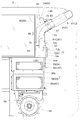
본 발명에 따른 수확기의 특징 구성은, 주행 기체에, 엔진과, 상기 엔진에 공급하는 연료를 저류하는 연료 탱크와, 상기 엔진의 배기 가스에 포함되는 질소산화물을 저감하는 배기 가스 정화 장치와, 상기 배기 가스 정화 장치에 공급하기 위한 요소수를 저류하는 요소수 탱크가 구비되고, 상기 요소수 탱크는 상기 연료 탱크와 인접하는 위치에 설치되어 있는 점에 있다.A characteristic feature of the harvester according to the present invention resides in that the running vehicle is provided with an engine, a fuel tank for storing fuel to be supplied to the engine, an exhaust gas purifying device for reducing nitrogen oxides contained in the exhaust gas of the engine, There is provided a urea water tank for storing urea water to be supplied to the exhaust gas purification apparatus, wherein the urea water tank is provided at a position adjacent to the fuel tank.
본 발명에 따르면, 요소수 탱크가 연료 탱크와 인접하는 위치에 설치되므로, 요소수와 연료를 보급하는 경우에, 요소수와 연료를 동일한 장소에서 보급하는 것이 가능해져, 작업 능률의 향상을 도모할 수 있다.According to the present invention, since the urea water tank is provided at a position adjacent to the fuel tank, when urea water and fuel are supplied, urea water and fuel can be supplied at the same place, .
본 발명에 있어서는, 상기 연료 탱크는 기체 프레임에 지지되고, 상기 요소수 탱크는 상기 연료 탱크의 상방에 구비되어 있으면 적합하다.In the present invention, it is preferable that the fuel tank is supported by the base frame and the urea water tank is provided above the fuel tank.
연료를 보충하고 나서 다음번 보충까지의 작동 시간을 길게 하기 위해서는, 연료 탱크는 저류량을 많게 해두는 편이 낫다. 그래서, 본 구성에서는, 대형이 되기 쉬운 연료 탱크는 기체 프레임으로써 안정적으로 지지할 수 있다. 한편, 비교적 소형의 요소수 탱크는, 연료 탱크의 상방에 구비하도록 하고 있다. 그 결과, 연료 탱크의 상방 공간을 유효하게 이용하여, 다른 부재의 배치에 영향을 주는 일없이 합리적으로 요소수 탱크를 배치할 수 있다.In order to increase the operating time from replenishing the fuel to the next replenishment, it is better for the fuel tank to make a large amount of storage. Therefore, in this configuration, the fuel tank, which tends to become large, can be stably supported by the base frame. On the other hand, a relatively small urea water tank is provided above the fuel tank. As a result, the upper space of the fuel tank can be effectively used, and the urea water tanks can be disposed reasonably without affecting the arrangement of the other members.
본 발명에 있어서는, 상기 연료 탱크는, 그 하단부가 상기 기체 프레임의 상면보다도 하방측으로 들어가는 상태에서, 상기 기체 프레임에 지지되어 있으면 적합하다.In the present invention, it is preferable that the fuel tank is supported by the base frame in a state in which the lower end of the fuel tank is lower than the upper surface of the base frame.
본 구성에 의하면, 연료 탱크를 기체 프레임에 대하여 낮은 위치에 구비할 수 있다. 연료 탱크의 상방에 위치하는 요소수 탱크의 상하 위치를 낮출 수 있어, 요소수의 보급 작업을 행하기 쉬운 것이 된다. 게다가, 대형이며 대중량의 연료 탱크를 낮은 위치로 함으로써, 기체 무게 중심 위치를 낮추어 주행 안정성을 높이는 이점도 있다.According to this configuration, the fuel tank can be provided at a lower position with respect to the base frame. The vertical position of the urea water tank located above the fuel tank can be lowered, and it becomes easy to perform the urea water supply work. In addition, there is an advantage in that the large, large-sized fuel tank is placed at a low position, thereby lowering the center of gravity position of the vehicle and improving the running stability.
본 발명에 있어서는, 상기 요소수 탱크를 지지하는 지지 프레임이 구비되고, 상기 지지 프레임은, 상기 연료 탱크의 측방을 통과하는 상태에서 상기 기체 프레임으로부터 상방을 향해 연장되어 있으면 적합하다.In the present invention, it is preferable that a support frame for supporting the urea water tank is provided, and the support frame extends upward from the base frame in a state of passing through the side of the fuel tank.
요소수 탱크를 연료 탱크의 상부에 직접 지지하는 구성이면, 연료 탱크의 지지 강도를 필요 이상으로 크게 할 필요가 있다. 이에 비해, 본 구성에 의하면, 연료 탱크의 지지 강도를 필요 이상으로 크게 하지 않고, 요소수 탱크를 지지 프레임으로써 안정적으로 지지할 수 있다.If the urea water tank is directly supported on the upper portion of the fuel tank, the support strength of the fuel tank needs to be increased more than necessary. By contrast, according to this configuration, the urea water tank can be stably supported as the support frame without increasing the support strength of the fuel tank more than necessary.
본 발명에 있어서는, 상기 주행 기체에, 곡립을 저류하는 곡립 탱크가 구비되고,In the present invention, the running vehicle is provided with a grape tanks for storing the grains,
상기 곡립 탱크의 후방부에, 상기 곡립 탱크 내의 곡립을 외부로 배출하는 곡립 배출 장치가 구비되고,And a curved discharging device for discharging the curl in the curled tanks to the outside is provided at a rear portion of the curled tanks,
상기 지지 프레임이 상기 주행 기체의 후단부에 구비되고, 상기 곡립 배출 장치가 상기 지지 프레임에 지지되어 있으면 적합하다.It is suitable that the support frame is provided at the rear end of the running vehicle, and the grainy paper discharging device is supported by the support frame.
본 구성에 의하면, 요소수 탱크를 지지하는 지지 프레임이 곡립 배출 장치를 지지하는 지지 프레임을 겸용하므로, 요소수 탱크용 지지 프레임과는 별도로 곡립 배출 장치 전용의 지지 프레임을 구비하는 구성에 비해 지지 구조의 간소화를 도모할 수 있다.According to this configuration, since the support frame for supporting the urea water tanks also serves as a support frame for supporting the curled discharge device, the support frame for the urea water tank is provided separately from the support frame for the urea water tank, Can be simplified.
본 발명에 있어서는, 상기 요소수 탱크에 저류되는 상기 요소수를 소비 개소까지 보내는 펌프가 구비되고, 상기 지지 프레임의 후방측 부분에 상기 요소수 탱크가 지지되고, 상기 지지 프레임의 전방측 부분에 상기 펌프가 지지되고, 상기 배기 가스 정화 장치는 상기 펌프보다도 전방측에 구비되어 있으면 적합하다.In the present invention, it is preferable that a pump for sending the urea water stored in the urea water tank to a consumption point is provided, the urea water tank is supported on a rear side portion of the support frame, It is preferable that the pump is supported and the exhaust gas purifying device is provided on the front side of the pump.
본 구성에 의하면, 펌프의 작동에 의해 요소수 탱크 내의 요소수를 배기 가스 정화 장치에 공급할 수 있다. 요소수 탱크가 최후방부측에 위치하고, 요소수 탱크의 전방측에 펌프가 위치하고, 펌프의 전방측에 배기 가스 정화 장치가 위치하므로, 요소수의 반송 경로가 불필요하게 길어지는 것을 피할 수 있다. 게다가, 기체 후방부측으로부터 요소수 탱크에 대하여 요소수를 보급할 때, 펌프가 작업에 방해되지 않으므로, 요소수의 보급 작업을 효율적으로 행할 수 있다.According to this configuration, the urea water in the urea water tank can be supplied to the exhaust gas purifying apparatus by the operation of the pump. The elliptical water tank is located on the rear end side, the pump is located on the front side of the urea water tank, and the exhaust gas purifying device is located on the front side of the pump, so that the conveyance path of the urea water can be avoided unnecessarily long. In addition, when the urea water is supplied to the urea water tank from the gas rear side, the pump does not interfere with the operation, so that the urea water supply work can be efficiently performed.
본 발명에 있어서는, 상기 지지 프레임은, 상기 연료 탱크의 전방측 및 후방측 각각에 있어서 상하 방향으로 연장되는 복수의 지주와, 그것들 복수의 지주의 상부끼리에 걸치는 적재대를 구비하고 있으면 적합하다.In the present invention, it is preferable that the support frame has a plurality of support columns extending in the vertical direction on the front side and a rear side of the fuel tank, respectively, and a loading table extending over the upper portions of the plurality of support columns.
본 구성에 의하면, 연료 탱크의 전후 양측에 설치된 전후 양측의 지주에 의해 적재대가 안정적으로 지지된다. 그렇게 지지되는 적재대에 요소수 탱크가 적재 지지되므로, 요소수 탱크를 안정적으로 지지할 수 있다.According to this configuration, the stacking pads are stably supported by the front and rear stanchions provided on both the front and rear sides of the fuel tank. Since the elliptical water tank is supported on the support stand so supported, the urea water tank can be stably supported.
본 발명에 있어서는, 상기 지지 프레임에, 상기 요소수 탱크에 대한 보급용 요소수를 저류하는 보급 용기를 적재 지지 가능한 보급 용기 적재대가 구비되어 있으면 적합하다.In the present invention, it is preferable that the supporting frame is provided with a replenishing container loading table capable of loading and storing a replenishing container for storing the number of replenishing elements for the urea water tank.
본 구성에 의하면, 요소수 탱크에 요소수를 보급할 때는, 작업자는, 보급용 요소수를 저류하는 보급 용기를 보급 용기 적재대에 적재하여 하중을 받아내어 지지시킨 상태로, 중량 부담이 적은 상태에서 쉽게 보급 작업을 행할 수 있다.According to this configuration, when the urea water is supplied to the urea water tank, the operator places the replenishing container storing the water for replenishment on the replenishing container mounting table, It is possible to easily perform the replenishment operation.
본 발명에 있어서는, 상기 주행 기체의 전방측에, 기체 주행에 수반하여 작물을 수확하는 수확부가 구비되고, 상기 연료 탱크 및 상기 요소수 탱크는, 상기 주행 기체의 후단부에 구비되어 있으면 적합하다.In the present invention, a harvesting section for harvesting a crop along with the running of the vehicle is provided on the front side of the running vehicle, and the fuel tank and the urea water tank are preferably provided at the rear end of the running vehicle.
본 구성에 의하면, 수확부가 주행 기체의 전방측에 구비되므로, 기체 전체로서 전후 중량 밸런스가 전중(前重) 상태가 되기 쉽다. 그래서, 연료 탱크 및 요소수 탱크를, 주행 기체의 후단부에 구비함으로써, 전후 중량 밸런스를 개선시킬 수 있다.According to this configuration, since the harvesting portion is provided on the front side of the traveling body, the balance of the front and back weights is liable to become a front weight state as a whole of the base body. Therefore, by providing the fuel tank and the urea water tank at the rear end portion of the running vehicle, the balance of the front and rear weights can be improved.
연료나 요소수를 보급할 때, 연료 탱크 및 요소수 탱크가 주행 기체의 후단부에 구비되는 점에서, 기체 후방측으로부터 작업을 행하는 경우에, 연료 탱크 및 요소수 탱크가 가까운 위치에 있어서 작업을 행하기 쉽다.When the fuel tank and the urea water tank are provided at the rear end of the traveling gas when the fuel or urea water is replenished, when the operation is performed from the gas rear side, the fuel tank and the urea water tank are close to each other It is easy to do.
본 발명에 있어서는, 상기 연료 탱크 및 상기 요소수 탱크 각각을 후방측으로부터 덮는 후방부 외장 커버가 구비되고,In the present invention, a rear outer cover covering the fuel tank and the urea water tank from the rear side is provided,
상기 후방부 외장 커버는, 상기 연료 탱크 및 상기 요소수 탱크를 덮는 작용 상태와, 상기 연료 탱크 및 상기 요소수 탱크의 후방측을 개방하는 비작용 상태로 자세 변경 가능하다면 적합하다.The rear outer cover is suitable if it is possible to change the posture to the non-operating state in which the fuel tank and the urea water tank are covered and the rear side of the fuel tank and the urea water tank are opened.
본 구성에 의하면, 수확 작업 시 등에 있어서는, 후방부 외장 커버를 작용 상태로 함으로써, 연료 탱크 및 요소수 탱크 각각을 후방측으로부터 덮을 수 있고, 외부의 장해물이 접촉되어 연료 탱크나 요소수 탱크가 손상되는 것을 방지할 수 있다. 한편, 연료나 요소수를 보급할 때는, 후방부 외장 커버를 비작용 상태로 자세 변경함으로써 대응할 수 있다.According to this configuration, when the harvesting operation is performed, the rear outer cover can be actuated to cover each of the fuel tank and the urea water tanks from the rear side, and an external obstacle comes in contact with the fuel tank and the urea water tank Can be prevented. On the other hand, when replenishing fuel or urea water, it is possible to cope by replenishing the posterior outer cover in a non-operating state.
본 발명에 있어서는, 상기 연료 탱크의 급유구가 상기 연료 탱크의 후방부측에 구비되고,In the present invention, the fuel filler port of the fuel tank is provided on the rear side of the fuel tank,
상기 요소수 탱크의 급수구가 상기 요소수 탱크의 후방부측에 구비되어 있으면 적합하다.It is suitable that a water supply port of the urea water tank is provided on the rear side of the urea water tank.
본 구성에 의하면, 기체 후방부측으로부터 보급 작업을 행하는 경우에 있어서, 급유구 및 급수구가 모두 작업자에 가까운 개소에 위치하므로, 번거로움이 없이 보급 작업을 행하기 쉽다.According to this configuration, in the case of performing the replenishing operation from the back side of the base, since both the refueling port and the water supply port are located in positions close to the operator, it is easy to perform the replenishing operation without inconvenience.
본 발명에 있어서는, 상기 급유구는, 상기 연료 탱크의 후방 벽부로부터 기체 후방을 향해 돌출되어 있으면 적합하다.In the present invention, it is preferable that the oil supply port projects from the rear wall portion of the fuel tank toward the rear of the gas.
본 구성에 의하면, 연료 탱크의 급유구가 후방 벽부로부터 기체 후방을 향해 돌출되어 있으므로, 연료 탱크의 상측에 위치하는 요소수 탱크를 연료 탱크의 상벽부에 가능한 한 근접시킬 수 있다. 요소수 탱크를 상벽부에 근접시켜 배치해도, 급유구로부터 연료의 보급 작업에 방해되지 않는다.According to this configuration, since the refueling port of the fuel tank protrudes from the rear wall portion toward the back of the gas, the urea water tank located on the upper side of the fuel tank can be made as close as possible to the upper wall portion of the fuel tank. Even if the urea water tank is arranged close to the upper wall portion, the fuel supply operation is not disturbed from the fuel supply port.
따라서, 연료의 보급 작업을 방해하는 일없이, 요소수 탱크를 낮은 위치에 설치할 수 있다.Therefore, the urea water tank can be installed at a low position without interfering with the fuel supply operation.
본 발명에 있어서는, 상기 연료 탱크와 상기 요소수 탱크 중 적어도 어느 한쪽에, 양자를 식별하기 위한 식별 표지가 구비되어 있으면 적합하다.In the present invention, it is preferable that at least one of the fuel tank and the urea water tank is provided with an identification mark for identifying them.
본 구성에 의하면, 연료 탱크의 급유구와 요소수 탱크의 급수구가 기체 후방부측에서 나열되는 상태로 구비되는 구성이어도, 작업자가 연료 또는 요소수의 보급 작업을 행하는 경우, 식별 표지에 의해, 연료를 공급해야 할 급유구인지, 요소수를 공급해야 할 급수구인지를 식별할 수 있다. 따라서, 적정한 보급 작업을 양호하게 행할 수 있다.According to this configuration, even if the water supply port of the fuel tank and the water inlet port of the urea water tank are provided in a state where they are arranged on the rear side of the gas supply line, when the operator performs the operation of replenishing fuel or urea water, It is possible to identify the supply port to be supplied and the supply port to which the urea number should be supplied. Therefore, proper dispensing work can be performed satisfactorily.
본 발명에 있어서는, 수확한 작물을 탈곡 처리하는 탈곡 장치와, 곡립을 저류하는 곡립 탱크가, 좌우 방향으로 나열되는 상태로 구비되고, 상기 요소수 탱크는, 상기 탈곡 장치와 상기 곡립 탱크 사이에 구비되어 있으면 적합하다.In the present invention, a threshing device for threshing the harvested crop and a grapefruit tank for storing the grains are arranged in a left-right direction, and the urea water tank is provided between the threshing device and the grapefruit tank Is appropriate.
본 구성에 의하면, 탈곡 장치에서 작물을 탈곡 처리하여 얻어진 곡립이, 탈곡 장치와 좌우 방향으로 나열되는 상태로 구비된 곡립 탱크에서 저류된다. 그리고, 요소수 탱크는, 좌우 양측에 탈곡 장치와 곡립 탱크가 구비되므로, 요소수 탱크는, 탈곡 장치와 곡립 탱크라는 대형 장치에 의해 보호됨으로써, 두렁이나 다른 장해물에 충돌하여 손상될 우려가 적다.According to this configuration, the grains obtained by threshing the crops in the threshing apparatus are stored in the grappling tank provided in a state in which they are arranged in the left-right direction with the threshing apparatus. Since the urea water tanks are provided on both sides of the left and right sides with the threshing device and the curling tanks, the urea water tanks are less likely to be damaged by colliding with the slugs or other obstacles by being protected by the threshing device and the large-
본 발명에 있어서는, 상기 주행 기체에, 수확한 작물을 탈곡 처리하는 탈곡 장치와, 곡립을 저류하는 곡립 탱크가, 좌우 방향으로 나열되는 상태로 구비되고,In the present invention, the traveling vehicle is provided with a threshing device for threshing the harvested crop and a grapefruit tank for storing the grains, which are arranged in the left-right direction,
상기 주행 기체의 전방부에 상기 배기 가스 정화 장치가 구비되고,Wherein the exhaust gas purifier is provided at a front portion of the traveling gas,
상기 주행 기체의 후방부에 상기 요소수 탱크가 구비되고,Wherein the urea water tank is provided at a rear portion of the traveling gas,
상기 요소수 탱크와 상기 배기 가스 정화 장치를 접속하는 배관이, 상기 탈곡 장치와 상기 곡립 탱크 사이를 통과하고 있으면 적합하다.It is preferable that a pipe connecting the urea water tank and the exhaust gas purifying device passes between the threshing device and the grainy tank.
본 구성에 의하면, 기체 전방부의 배기 가스 정화 장치와 기체 후방부의 요소수 탱크가, 탈곡 장치와 곡립 탱크 사이를 통과하는 배관으로 접속된다. 배관은, 탈곡 장치와 곡립 탱크에 의해 보호된다. 따라서, 탈곡 장치와 곡립 탱크 사이의 빈 영역을 유효하게 이용하여, 외물(外物)과의 접촉에 의한 손상을 받을 우려가 적은 상태로, 배관을 양호하게 배치할 수 있다.According to this configuration, the exhaust gas purifier of the gas front part and the urea water tank of the gas rear part are connected by a pipe passing between the threshing device and the grape tanks. The piping is protected by a threshing device and a graining tank. Accordingly, the hollow space between the threshing device and the curling tanks can be effectively used, and the piping can be disposed in a good condition with less risk of being damaged by contact with the outer product.
본 발명에 있어서는, 상기 탈곡 장치와 상기 곡립 탱크 사이에 위치하여, 상기 탈곡 장치의 하부에서 회수된 곡립을 상기 곡립 탱크의 상부로 반송하는 양곡 장치가 구비되고,In the present invention, there is provided a grain machine which is positioned between the threshing device and the grape tanks and transports the grains recovered from the lower portion of the threshing device to the upper portion of the grape tanks,
상기 배관은, 상기 탈곡 장치와 상기 양곡 장치 사이를 통과하고 있으면 적합하다.The pipe is suitable if it passes between the threshing device and the grain machine.
본 구성에 의하면, 탈곡 장치와 양곡 장치 사이의 간극을 유효하게 이용하여 배관을 배치할 수 있다.According to this configuration, it is possible to arrange the pipe by effectively utilizing the clearance between the threshing device and the grain device.
본 발명에 있어서는, 상기 탈곡 장치와 상기 곡립 탱크 사이에 위치하여, 상기 탈곡 장치의 하부에서 회수된 2번물을 상기 탈곡 장치의 전방부로 환원하는 2번물 환원 장치가 구비되고,In the present invention, there is provided a two-burner reduction device which is located between the threshing device and the curling tanks and reduces the two pieces recovered from the lower portion of the threshing device to the front portion of the threshing device,
상기 배관은, 상기 2번물 환원 장치의 상방을 통하고 있으면 적합하다.The pipe is suitable if it passes above the two-piece reduction device.
2번물 환원 장치는, 2번물을 복귀시키는 위치가 탈곡 장치의 상하 중간 위치이기 때문에, 그 상방측에는 빈 공간이 있다. 본 구성에 의하면, 그 빈 공간을 유효하게 이용하여 배관을 배치할 수 있다.In the two-burner reduction device, since the position for returning the second item is the upper and lower middle position of the threshing device, there is an empty space above the second device. According to this configuration, the piping can be arranged by effectively utilizing the empty space.
본 발명에 있어서는, 상기 탈곡 장치와 상기 곡립 탱크 사이에 있어서의 상기 배관의 상방 개소에, 작업대가 설치되어 있으면 적합하다.In the present invention, it is preferable that a workbench is provided at a position above the pipe between the threshing device and the grainy tank.
본 구성에 의하면, 작업대를 사용함으로써 작업자가 탈곡 장치나 곡립 탱크에 대하여 메인터넌스 작업을 행하는 것을, 배관에 악영향을 주지 않는 상태에서 양호하게 행할 수 있다.According to this configuration, by using the workbench, it is possible for the operator to perform the maintenance work on the threshing device or the grapefruit tank in a satisfactory condition without adversely affecting the piping.
본 발명에 있어서는, 상기 배관을 지지하는 배관 지지 부재가 구비되고, 상기 작업대가 상기 배관 지지 부재에 지지되어 있으면 적합하다.In the present invention, it is preferable that a piping support member for supporting the piping is provided and the worktable is supported by the piping support member.
본 구성에 의하면, 배관 지지 부재는, 배관을 지지함과 함께 작업대를 지지한다. 작업대 전용의 지지 부재를 설치할 필요가 없고, 부재의 겸용에 의해 구조의 간소화를 도모할 수 있다.According to this configuration, the piping support member supports the worktable while supporting the piping. It is not necessary to provide a support member dedicated to the workbench, and the structure can be simplified by combining the members.
(4) 과제 4에 대응하는 해결 수단은 이하와 같다.(4) The solution to the
본 발명에 따른 수확기의 특징 구성은,The characteristic configuration of the harvester according to the present invention is that,
주행 기체와, 상기 주행 기체의 전방측에 위치하여, 주행에 수반하여 작물을 수확하는 수확부가 구비되고,And a harvesting unit located on the front side of the traveling vehicle for harvesting crops along with running,
상기 주행 기체의 전방부에, 엔진 및 상기 엔진의 배기 가스에 포함되는 질소산화물을 저감하는 배기 가스 정화 장치가 구비되고,An exhaust gas purifying device for reducing nitrogen oxide contained in the engine and exhaust gas of the engine is provided in the front portion of the traveling gas,
상기 주행 기체의 후방부에, 상기 배기 가스 정화 장치에 공급하기 위한 요소수를 저류하는 요소수 탱크가 구비되어 있는 점에 있다.And a urea water tank for storing urea water to be supplied to the exhaust gas purifier is provided at a rear portion of the traveling gas.
본 발명에 따르면, 주행 기체의 전방부에 엔진 및 배기 가스 정화 장치가 구비되므로, 엔진과 배기 가스 정화 장치를 가깝게 한 상태로 구비할 수 있고, 그것들을 접속하는 배기 가스 통류용 배관이 짧아져, 배관 구조가 간단해진다.According to the present invention, since the engine and the exhaust gas purifier are provided in the front portion of the traveling gas, the engine and the exhaust gas purifier can be provided close to each other, and the exhaust gas passageway pipe connecting them is shortened, The piping structure is simplified.
수확기에 있어서는, 기체 후방부측에 위치하는 상태에서, 수확한 작물의 처리를 행하는 작물 처리 장치 등의 다른 장치가 구비된다. 요소수 탱크는, 배기 가스 정화 장치에 비해 소형의 장치이다. 그래서, 소형의 장치인 요소수 탱크를 주행 기체의 후방부에 구비함으로써, 다른 장치의 레이아웃에 영향을 주는 일이 없는 상태에서, 배기 가스 처리에 필요한 설비를 배치할 수 있다.In the harvester, another apparatus such as a crop processing apparatus for treating the harvested crop in a state of being located on the rear side of the base is provided. The urea water tank is a smaller apparatus than the exhaust gas purifying apparatus. Therefore, by providing the urea water tank, which is a compact device, in the rear portion of the traveling gas, it is possible to arrange the facilities necessary for the exhaust gas treatment in a state in which the layout of the other devices is not affected.
따라서, 배기 가스 처리에 필요한 설비를 다른 장치의 레이아웃에 영향을 주는 일없이 배치하여, 배기 가스 처리용의 구성을 간소화할 수 있다.Accordingly, the arrangement necessary for the exhaust gas treatment can be arranged without affecting the layout of the other apparatus, and the structure for treating the exhaust gas can be simplified.
본 발명에 있어서는, 상기 요소수 탱크가 상기 주행 기체의 후단부에 구비되어 있으면 적합하다.In the present invention, it is preferable that the urea water tank is provided at the rear end of the traveling vehicle.
요소수는 배기 가스 처리를 실행함에 따라서 소비되므로, 잔량이 적어지면 보충할 필요가 있다. 본 구성에 의하면, 요소수 탱크가 주행 기체의 후단부에 구비되므로, 요소수 탱크가 기체 후방 외측에 면하는 상태로 구비된다. 그 결과, 기체 후방측으로부터 요소수의 보충 작업을 용이하게 행할 수 있다.Since the number of urea is consumed by performing the exhaust gas treatment, it is necessary to replenish when the remaining amount becomes small. According to this configuration, since the urea water tank is provided at the rear end portion of the traveling gas, the urea water tank is provided so as to face the outside of the gas rear. As a result, the urea water replenishing operation can be easily performed from the gas rear side.
본 발명에 있어서는, 상기 엔진은 상기 주행 기체의 좌우 방향 일방측에 구비되고,In the present invention, the engine is provided on one side in the lateral direction of the running vehicle,
상기 주행 기체의 좌우 방향 타방측에, 수확한 작물을 탈곡 처리하는 탈곡 장치가 구비되고,And a threshing device for threshing the harvested crop is provided on the other side in the lateral direction of the running vehicle,
상기 탈곡 장치의 상기 좌우 방향 일방측의 측방에 상기 요소수 탱크가 구비되어 있으면 적합하다.It is preferable that the urea water tank is provided on the side of one side of the threshing device in the left-right direction.
본 구성에 의하면, 요소수 탱크가 탈곡 장치의 좌우 방향 일방측, 즉, 기체 내측이며 또한 엔진 존재측의 측방에 구비된다. 그 결과, 요소수 탱크와 엔진에 가까운 개소에 구비되는 배기 가스 정화 장치 사이의 배관을 설치하기 쉬워지고, 게다가, 요소수 탱크를 탈곡 장치에 의해 보호할 수 있다.According to this configuration, the urea water tank is provided on one side in the left and right direction of the threshing device, that is, on the gas inside side and on the side of the engine present side. As a result, it is easy to install the piping between the urea water tank and the exhaust gas purifier provided at a position close to the engine, and furthermore, the urea water tank can be protected by the threshing device.
본 발명에 있어서는, 상기 요소수 탱크와 상기 배기 가스 정화 장치를 접속하는 배관이, 상기 탈곡 장치의 상기 좌우 방향 일방측의 측벽을 따르는 상태로 구비되어 있으면 적합하다.In the present invention, it is preferable that a pipe connecting the urea water tank and the exhaust gas purifying device is provided along the side wall on one side in the left-right direction of the threshing device.
본 구성에 의하면, 배관이 탈곡 장치의 측벽을 따르게 한 상태로 구비되므로, 배관은, 탈곡 장치의 좌우 방향 타방측에 설치되는 다른 장치와 간섭하지 않다. 즉, 다른 장치의 설치에 제약을 주는 일이 없는 상태로 배관을 구비할 수 있다.According to this configuration, since the piping is provided along the side wall of the threshing device, the piping does not interfere with other devices installed on the other side in the lateral direction of the threshing device. That is, the piping can be provided in a state in which there is no restriction on the installation of another apparatus.
본 발명에 있어서는, 상기 배관이, 상기 탈곡 장치의 상기 좌우 방향 일방측의 측벽 상부를 따르는 상태로 구비되어 있으면 적합하다.In the present invention, it is preferable that the pipe is provided so as to follow the upper portion of the side wall on one side in the left-right direction of the threshing device.
본 구성에 의하면, 배관이 탈곡 장치의 측벽 상부를 따르는 상태로 구비되므로, 배관이 2번물(二番物) 환원 장치 등의 탈곡 장치의 측벽에 구비되는 장치와 간섭하는 경우가 없다.According to this configuration, since the piping is provided along the upper portion of the side wall of the threshing device, the piping does not interfere with the device provided on the side wall of the threshing device such as a two-piece reduction device.
본 발명에 있어서는, 상기 탈곡 장치의 상기 좌우 방향 일방측의 측벽에, 상기 배관을 지지하는 지지 부재가 구비되어 있으면 적합하다.In the present invention, it is preferable that a side wall on one side in the left-right direction of the threshing device is provided with a supporting member for supporting the pipe.
본 구성에 의하면, 배관이 지지 부재에 의해 지지되므로, 배관은 기체의 진동에 의해 흔들리는 일없이, 자세가 안정된다.According to this configuration, since the piping is supported by the supporting member, the piping is stabilized in posture without being shaken by the vibration of the base body.
본 발명에 있어서는,In the present invention,
상기 주행 기체의 전방부에 있어서, 기체 프레임에 상기 엔진이 지지됨과 함께, 상기 엔진 상에 상기 배기 가스 정화 장치가 구비되고,Wherein the engine is supported on a gas frame in a front portion of the traveling gas and the exhaust gas purifying device is provided on the engine,
상기 주행 기체의 후방부에 있어서, 상기 기체 프레임에 연료 탱크가 지지됨과 함께, 상기 연료 탱크 상에 상기 요소수 탱크가 구비되고,A fuel tank is supported on the base frame at the rear portion of the running vehicle and the urea water tank is provided on the fuel tank,
상기 배관은 대략 직선상으로 연장되어 있으면 적합하다.It is suitable if the pipe extends approximately in a straight line.
본 구성에 의하면, 기체 전방부측에서는, 기체 프레임에 의해 안정적으로 엔진이 지지되고, 그 엔진의 상측 공간을 이용하여 배기 가스 정화 장치가 구비된다. 기체 후방부측에서는, 기체 프레임에 안정적으로 대형의 연료 탱크가 지지되고, 그 상측의 공간을 이용하여 요소수 탱크가 구비된다. 이와 같이, 배기 가스 정화 장치와 요소수 탱크가 기체 프레임보다도 상방의 높은 위치에 구비되고, 그와 같이 높은 위치에 있는 배기 가스 정화 장치와 요소수 탱크가 대략 직선상으로 연장되는 배관으로써 접속된다.According to this configuration, on the gas front side, the engine is stably supported by the gas frame, and the exhaust gas purifying device is provided using the upper space of the engine. On the gas rear side, a large-sized fuel tank is stably supported on the base frame, and a urea water tank is provided using the space above the base. Thus, the exhaust gas purifying apparatus and the urea water tank are provided at higher positions above the gas frame, and the exhaust gas purifying apparatus at such a high position and the urea water tank are connected by a pipe extending substantially in a straight line.
엔진이나 연료 탱크의 상방 공간을 유효 이용하여, 다른 장치의 배치에 제약을 주는 일없이, 배기 가스 정화 장치와 요소수 탱크를 합리적으로 배치할 수 있고, 게다가, 배관이 짧아져 배관 구조를 간소화할 수 있는 이점도 있다.The exhaust gas purifying device and the urea water tank can be rationally arranged without any restriction on the arrangement of the other devices by efficiently utilizing the space above the engine or the fuel tank and further the piping is shortened to simplify the piping structure There is also an advantage.
본 발명에 있어서는, 상기 주행 기체의 좌우 방향 일방측에, 상기 탈곡 장치와 좌우 방향으로 나열되는 상태로 곡립 탱크가 구비되고,According to the present invention, the curling tanks are provided on one side of the traveling body in the lateral direction,
상기 요소수 탱크는, 상기 탈곡 장치와 상기 곡립 탱크 사이에 구비되어 있으면 적합하다.The urea water tank is preferably provided between the threshing device and the curling tanks.
본 구성에 의하면, 탈곡 장치에서 작물을 탈곡 처리하여 얻어진 곡립이, 탈곡 장치와 좌우 방향으로 나열되는 상태로 구비된 곡립 탱크에서 저류된다. 그리고, 요소수 탱크는, 좌우 양측에 탈곡 장치와 곡립 탱크가 구비되므로, 요소수 탱크는, 탈곡 장치와 곡립 탱크라는 대형의 장치에 의해 보호됨으로써, 두렁이나 다른 장해물에 충돌하여 손상될 우려가 적다.According to this configuration, the grains obtained by threshing the crops in the threshing apparatus are stored in the grappling tank provided in a state in which they are arranged in the left-right direction with the threshing apparatus. Since the urea water tanks are provided with a threshing device and a curling tank on both sides of the urea water tank, the urea water tank is protected by a large apparatus such as a threshing device and a curling tank, .
본 발명에 있어서는, 상기 곡립 탱크에 하향 협소 형상의 경사면이 구비되고,In the present invention, the grainy tank is provided with a downwardly narrow sloped surface,
상기 탈곡 장치와 상기 곡립 탱크 사이에 있어서, 상기 곡립 탱크의 상기 경사면의 외측에 형성된 공간에, 연료 탱크가 구비되고,A fuel tank is provided in a space formed outside the inclined surface of the curling tank between the curling apparatus and the curling tank,
상기 연료 탱크 상에 상기 요소수 탱크가 구비되어 있으면 적합하다.It is suitable if the urea water tank is provided on the fuel tank.
본 구성에 의하면, 곡립 탱크는, 하향 협소 형상의 경사면을 구비함으로써, 하단부에 구비되는, 예를 들어 스크류 컨베이어 등으로 이루어지는 반송 장치를 향해 유하 안내할 수 있다. 그리고, 이렇게 경사상으로 형성된 곡립 탱크의 외측 공간을 이용하여 연료 탱크를 구비함으로써, 다른 장치에 제약을 주는 일없이, 연료 탱크를 대용량화하는 것이 가능해진다.According to this configuration, the curling tanks can be guided downward toward the conveying device provided at the lower end portion, for example, a screw conveyor or the like, by having the inclined surface having a downwardly narrow shape. By providing the fuel tank using the outer space of the tortuous tanks formed in this manner, it becomes possible to increase the capacity of the fuel tank without restricting other devices.
도 1은 콤바인의 전체 좌측면도이다.
도 2는 콤바인의 전체 평면도이다.
도 3은 콤바인의 전체 우측면도이다.
도 4는 콤바인의 후방부 외장 커버를 떼어낸 상태의 배면도이다.
도 5는 콤바인의 배면도이다.
도 6은 배기 가스 정화용 배관 구조를 나타내는 측면도이다.
도 7은 배기 가스 정화 장치 설치부의 종단 배면도이다.
도 8은 엔진 주변의 측면도이다.
도 9는 연료 탱크 및 요소수 탱크의 지지 구조를 나타내는 배면도이다.
도 10은 곡립 탱크 및 주변의 평면도이다.
도 11은 엔진과 배기 가스 처리용 설비를 나타내는 사시도이다.
도 12는 엔진과 배기 가스 처리용 설비를 나타내는 측면도이다.
도 13은 배기관 배치부의 평면도이다.
도 14는 배기관 커버의 지지 구조를 나타내는 분해 사시도이다.
도 15는 기체 프레임의 일부 사시도이다.
도 16은 배관 지지용의 구성을 나타내는 사시도이다.
도 17은 다른 실시 형태의 요소수 탱크 배치부의 측면도이다.Figure 1 is an entire left side view of the combine.
2 is a plan view of the entire combine.
3 is a full right side view of the combine.
4 is a rear view of the combine with the rear outer cover removed therefrom.
5 is a rear view of the combine.
6 is a side view showing the exhaust gas purifying piping structure.
7 is a rear end elevational view of the exhaust gas purifying apparatus installing portion.
8 is a side view of the vicinity of the engine.
9 is a rear view showing a supporting structure of the fuel tank and the urea water tank.
10 is a plan view of the grained tank and its surroundings.
11 is a perspective view showing an engine and an exhaust gas processing facility.
12 is a side view showing an engine and an exhaust gas treatment facility.
13 is a plan view of the exhaust pipe arrangement portion.
14 is an exploded perspective view showing the supporting structure of the exhaust pipe cover.
15 is a partial perspective view of the gas frame.
16 is a perspective view showing a structure for supporting piping.
17 is a side view of the urea water tank arranging portion according to another embodiment.
이하, 본 발명에 따른 수확기의 일례인 콤바인의 실시 형태를 도면에 기초하여 설명한다. 이 실시 형태에서, 기체의 전후 방향을 정의할 때는, 작업 상태에 있어서의 기체 진행 방향을 따라서 정의하고, 기체의 좌우 방향을 정의할 때는, 기체 진행 방향에서 본 상태에서 좌우를 정의한다. 즉, 도 1, 2, 3에 부호(F)로 나타내는 방향이 기체 전방측, 도 1, 2, 3에 부호(B)로 나타내는 방향이 기체 후방측이다. 도 2에 부호(L)로 나타내는 방향이 기체 좌측, 도 2에 부호(R)로 나타내는 방향이 기체 우측이다.BEST MODE FOR CARRYING OUT THE INVENTION Hereinafter, an embodiment of a combine, which is an example of a harvester according to the present invention, will be described with reference to the drawings. In this embodiment, the forward and backward directions of the gas are defined according to the gas advancing direction in the working state, and the left and right directions are defined in the gas guiding direction when defining the gas lateral direction. That is, the direction indicated by reference character F in FIGS. 1, 2, and 3 is the gas front side, and the direction indicated by reference symbol B in FIGS. 1, 2, and 3 is the gas rear side. The direction indicated by the letter (L) in Fig. 2 is the left side of the body, and the direction indicated by (R) in Fig. 2 is the right side of the body.
[전체 구성][Overall configuration]
도 1, 2, 3에, 본 발명에 따른 수확기로서의 보통형 콤바인을 나타내고 있다. 이 콤바인은, 벼, 보리, 메밀, 대두, 옥수수 등의 작물을 수확할 수 있다.Figs. 1, 2 and 3 show an ordinary combine harvester according to the present invention. The combine harvests crops such as rice, barley, buckwheat, soybean, and corn.
이 콤바인은, 주행 기체(1)와, 주행 기체(1)의 전방측에 위치하여, 주행에 수반하여 작물을 수확하는 수확부로서의 예취부(2)를 구비하고 있다. 주행 기체(1)는, 좌우 한 쌍의 크롤러식 주행 장치(3)와, 주행 장치(3)로 지지되는 기체 프레임(4)을 구비하고 있다. 기체 프레임(4)의 전방부에 예취부(2)가 승강 가능하게 연결되어 있다. 주행 기체(1)의 전방부 우측에는 운전부(6)가 구비되고, 운전부(6)의 하방에는 원동부(7)가 구비되어 있다. 주행 기체(1)의 후방부에는, 예취 작물을 탈곡하는 탈곡 장치(8) 및 탈곡 처리에서 얻어진 곡립을 저류하는 곡립 탱크(9)가 기체 좌우 방향으로 나열되는 상태로 구비되어 있다.The combine has a traveling
도 1, 2에 나타내는 바와 같이, 운전부(6)의 후방부와 탈곡 장치(8)의 전방부가 기체 측면에서 보아 중복되는 상태에서, 운전부(6)가 주행 기체(1)의 좌우 방향 일방측으로서의 기체 우측에 설치됨과 함께, 탈곡 장치(8)가 주행 기체(1)의 좌우 방향 타방측으로서의 기체 좌측에 설치되어 있다.The
운전부(6)에는, 운전 좌석(10), 미터 패널(11), 사이드 패널(12), 조향 레버(13) 등이 비치되어 있다. 운전부(6)에, 운전 좌석(10)의 상방 공간을 덮는 캐빈(5)이 구비되어 있다. 캐빈(5)의 우측면에는, 탑승자가 출입하는 승강구(14)가 구비되어 있다. 사이드 패널(12)은 승강구(14)와는 반대측의 운전 좌석(10)의 좌횡측에 구비되어 있다. 사이드 패널(12)에는, 주변속 레버(15) 외에도, 작업용 클러치 레버(16) 등도 구비되어 있다.The
예취부(2)에는, 식립(植立) 작물을 예취 대상과 비예취 대상으로 나누는 좌우 한 쌍의 디바이더(17)와, 식립 작물을 긁어모으는 긁어모으기 릴(18)과, 식립 작물을 절단하는 바리캉형 예취 장치(19)와, 예취 작물을 예취폭 방향 중앙측으로 모으는 오거(20)와, 예취 작물을 탈곡 장치(8)로 반송하는 피더(21)가 구비되어 있다.The
예취부(2)에서는, 좌우 한 쌍의 디바이더(17)에 의해 구분된 예취 대상의 식립 작물이 긁어모으기 릴(18)에 의해 긁어 넣어진다. 그리고, 긁어모으기 릴(18)로 긁어모은 식립 작물이 예취 장치(19)에 의해 밑동이 절단된다. 예취된 예취 작물의 전부가 오거(20)로 좌우 방향 중앙측으로 모일 수 있으며, 피더(21)에 의해 탈곡 장치(8)의 급실(扱室)로 반송된다.In the preloading section (2), the cutting crops to be cut, which are separated by a pair of left and right dividers (17), are scraped by the raking reel (18). Then, the ground crops scraped by the raking
탈곡 장치(8)는 급실 내에 구비된 급동(扱胴)(22)과, 그 하방측에 구비된 수망(受網)(도시하지 않음)에 의해, 반송된 예취 작물의 탈곡 처리를 실행한다. 급실의 하방에 구비된 선별부(23)에서, 수망을 누하(漏下)한 탈곡 처리물을 곡립과 배출 짚 부스러기 등으로 선별한다. 탈곡 장치(8)의 기체 후방부에는, 배출 짚 부스러기를 세단 처리하여 하방 외측으로 배출하는 배출 짚 세단 장치(24)가 구비되어 있다.The threshing
도시하지는 않았지만, 배출 짚 세단 장치(24)는, 횡축심 주위로 회전하는 회전날과 위치 고정의 고정날을 구비하고, 탈곡 장치(8)의 후방부로부터 배출되는 배출 짚 부스러기를 세단하여 외측으로 배출한다. 그리고, 세단한 처리물을 하방 외측으로 배출시키는 안내 커버(24a)를 구비하고 있다. 도 2에 도시한 바와 같이, 안내 커버(24a)는, 좌측면은 전후 방향을 따르는 상태로 설치되고, 우측면은 기체 후방측일수록 우측에 위치하는 비스듬한 자세로 설치되어 있다. 이렇게 구성함으로써, 세단한 처리물을 기체 횡방향 중앙측으로 안내하도록 하고 있다.Although not shown, the discharge
도 1, 2에 나타내는 바와 같이, 곡립 탱크(9)의 기체 전방부측에서 또한 탈곡 장치(8)측의 우횡측 개소에, 탈곡 장치(8)의 하부에서 회수된 곡립을 곡립 탱크(9)의 상부로 반송하는 버킷 컨베이어식의 양곡 장치(25)가 구비되어 있다. 선별부(23)에 의한 선별 처리로 얻어진 곡립은, 1번물(一番物) 반송 스크류(27)로써 탈곡 장치(8)의 우횡측 외측으로 반송된 후, 양곡 장치(25)에서 상방으로 반송되어 곡립 탱크(9)에 공급된다.1 and 2, the corn recovered from the lower portion of the threshing
도 1, 6에 나타내는 바와 같이, 탈곡 장치(8)의 하부에서 회수된 가지 달린 벼 등의 2번물을 탈곡 장치(8)의 전방부로 환원하는 2번물 환원 장치(26)가 구비되어 있다. 이 2번물 환원 장치(26)는 탈곡 장치(8)와 곡립 탱크(9) 사이에 위치하여, 탈곡 장치(8)의 우횡측 개소에 양곡 장치(25)와 좌우 방향으로 나열되는 상태로 구비되어 있다. 선별부(23)에서 발생한 가지 달린 벼 등의 2번물은, 2번물 반송 스크류(28)에서 탈곡 장치(8)의 우횡측 외측으로 반송된 후, 2번물 환원 장치(26)에 의해 선별부(23)의 상부로 환원된다.As shown in Figs. 1 and 6, there is provided a two-
곡립 탱크(9)의 후방부에는, 그 내부에 저류되어 있는 곡립을 외부로 배출하는 곡립 배출 장치(29)가 구비되어 있다. 곡립 배출 장치(29)는, 곡립을 상방으로 반송하는 종스크류 컨베이어(29A)와, 이 종스크류 컨베이어(29A)의 상단부로부터 곡립을 횡방향으로 반송하여 선단의 배출구로부터 배출하는 횡스크류 컨베이어(29B)를 구비하고 있다.At the rear portion of the
도 4에 도시한 바와 같이, 곡립 탱크(9)의 하부에는 기체 전후 방향에서 볼 때 하향 협소 형상의 경사면(30)이 구비되어 있다. 곡립 탱크(9) 내부에 있어서의 경사면(30)의 하단부에는, 저류되어 있는 곡립을, 곡립 배출 장치(29)에 있어서의 종스크류 컨베이어(29A)의 반송 시단부까지 전후 방향을 따라서 반송하는 저스크류(32)가 구비되어 있다(도 3 참조). 그리고, 도 4에 도시한 바와 같이, 저스크류(32)와 종스크류 컨베이어(29A)의 도시되지 않은 반송 스크류가 벨트 전동 기구(31)를 통해 연동 연결되고, 또한 각부(角部) 케이스(33) 내의 곡립 통로를 통과하여, 곡립 탱크(9)로부터 종스크류 컨베이어(29A)로 곡립을 이송할 수 있다.As shown in Fig. 4, the lower portion of the
종스크류 컨베이어(29A)는, 횡스크류 컨베이어(29B)와 함께, 종축심(Y)(종스크류 컨베이어(29A)의 회전 축심) 주위로 회동 가능하게 기체 프레임(4)에 지지되어 있다. 도 4에 도시한 바와 같이, 종스크류 컨베이어(29A)의 좌횡측에, 각통재로 이루어지는 후방부측 종프레임(79)이 설치되어 있다. 후방부측 종프레임(79)은 하단이 기체 프레임(4)에 고정되어 있다. 종스크류 컨베이어(29A)는, 하단부가 각부 케이스(33)에 종축심(Y) 주위로 회동 가능하게 지지되고, 상하 중간부가 각통상의 후방부측 종프레임(79)의 상부에 지지 브래킷(35)을 통해 회동 가능하게 지지되어 있다. 종스크류 컨베이어(29A)의 하단부는, 각부 케이스(33) 및 회동 보스부(36)를 통해 기체 프레임(4)에 의해 하중을 받아내어 지지되고 있다.The
곡립 탱크(9)는, 종축심(Y)(종스크류 컨베이어(29A)의 회전 축심) 주위로 회동 가능하게 기체 프레임(4)에 지지되어 있다. 곡립 탱크(9)의 후방 하부는, 각부 케이스(33)를 통해 회동 보스부(36)에 대하여 종축심(Y) 주위로 회동 가능하게 지지되어 있다. 곡립 탱크(9)의 후방 상부는, 지지 브래킷(37)을 통해 종축심(Y) 주위로 회동 가능하게 종스크류 컨베이어(29A)에 지지되어 있다.The
도 4, 10에 나타내는 바와 같이, 각부 케이스(33)의 외주부에, 곡립 배출 장치(29)를 종축심(Y) 주위로 회동시키는 구동 기구(38)가 구비되어 있다. 구동 기구(38)는 전동 모터(39)로 구동되는 소직경 기어(도시하지 않음)를 종스크류 컨베이어(29A)의 외주부에 설치된 대직경 기어(40)를 맞물려 연동시켜 곡립 배출 장치(29)를 종축심(Y) 주위로 회동시킨다.4 and 10, a
후방부측 종프레임(79)은, 곡립 탱크(9)를 회동 가능하게 지지하기 때문에 큰 부하가 걸린다. 그래서, 후방부측 종프레임(79)을 탈곡 장치(8)의 측벽(8a)으로부터 횡방향으로 연장되는 보강 프레임(41)에 의해 지지하고 있다. 도 10에 도시한 바와 같이, 보강 프레임(41)은 각통재를 평면에서 보아 대략 L자형으로 절곡하여 구성되어 있다. 보강 프레임(41)의 전후 방향 부분(41A)은, 도시하지 않았지만, 탈곡 장치(8)의 측벽(8a)에 연결되어, 보강 프레임(41)의 횡방향 부분(41B)이 후방부측 종프레임(79)에 연결되어 있다. 보강 프레임(41)은, 전후 방향 부분(41A)과 횡방향 부분(41B)에 걸쳐 광폭의 판상 리브(41C)를 연결하여 보강을 도모하고 있다.The rear-side
도 6, 7에 나타내는 바와 같이, 원동부(7)에는, 엔진 보닛(42)에 의해 구획 형성되는 상태에서 엔진룸(43)이 형성되어 있다. 엔진 보닛(42)은 상부면(42a)과 전방부 종벽부(42b)를 구비하고, 이 엔진 보닛(42)에 의해, 엔진룸(43)과 운전용 공간이 구획되어 있다. 엔진 보닛(42)의 상부면(42a)의 상방에 운전 좌석(10)이 지지되어 있다. 도 7에 나타내는 바와 같이, 엔진 보닛(42)에 있어서의 상부측 부분 중 운전 좌석(10)의 좌횡측에 위치하는 개소에 상방으로 돌출되는 돌출부(42t)는, 사이드 패널(12)의 하측에 위치하고, 사이드 패널(12)의 프레임을 구성하고 있다.As shown in Figs. 6 and 7, an
[배기 가스 정화 장치][Exhaust gas purifying device]
도 7에 나타내는 바와 같이, 엔진룸(43) 내에, 디젤 엔진(44)(이하, 엔진이라 약칭함)과, 엔진 냉각용 라디에이터(45)와, 라디에이터(45)에 공급하는 냉각풍을 생기하는 라디에이터 냉각팬(46)과, 엔진(44)의 배기 가스에 포함되는 입자상 물질(PM)(Particulate Matter)을 감소시키는 별도의 배기 가스 정화 장치로서의 제1 배기 가스 정화 장치(47)와, 엔진(44)의 배기 가스에 포함되는 질소산화물(NOx)을 감소시키는 배기 가스 정화 장치로서의 제2 배기 가스 정화 장치(48)를 구비하고 있다. 엔진(44)은 엔진 보닛(42)의 전방부 종벽부(42b)의 후방측에 위치하는 상태로 구비된다. 제2 배기 가스 정화 장치(48)는 엔진룸(43) 중 엔진 보닛(42)의 돌출부(42t)에 대응하는 돌출부 형성 영역에 배치되어 있다.7, a diesel engine 44 (hereinafter abbreviated as an engine), an
제1 배기 가스 정화 장치(47)는, 배기 가스에 포함되는 디젤 미립자를 포집하는 공지 기술인 디젤 미립자 포집 필터(DPF)(Diesel Particulate Filter)(도시하지 않음)를 구비하고, 이 디젤 미립자 포집 필터(DPF)를 배기 가스가 통과함으로써 입자상 물질(PM)을 감소시킨다.The first exhaust
제2 배기 가스 정화 장치(48)는 SCR(Selective Cataltic Reduction)(선택적 촉매 환원)을 사용하여 배기 가스에 포함되는 질소산화물(NOx)을 감소시킨다. 설명을 부가하면, 환원제의 일례인 요소수를 배기 가스 중에 분사하여 가수 분해시켜 암모니아를 생성하고, 그 암모니아(NH3)와 배기 가스에 포함되는 질소산화물(NOx)을 화학 반응시켜, 질소(N2)와 물(H2O)로 환원시킴으로써 배기 가스 중에 포함되는 질소산화물을 감소시킨다.The second exhaust
도 8에 나타내는 바와 같이, 제1 배기 가스 정화 장치(DPF)(47)와 제2 배기 가스 정화 장치(SCR)(48)는, 엔진(44)과 일체적으로 고정되는 상태에서 엔진(44)의 상부에 지지되어 있다.The first exhaust gas purifying device (DPF) 47 and the second exhaust gas purifying device (SCR) 48 are connected to the
도 7에 나타내는 바와 같이, 제1 배기 가스 정화 장치(47)는, 엔진(44)에 있어서의 라디에이터 냉각팬(46)이 존재하는 측과는 반대측, 즉, 기체 좌측의 측방 중 엔진(44)의 상부에 대응하는 위치에 구비되어 있다.7, the first exhaust
도 8에 나타내는 바와 같이, 제2 배기 가스 정화 장치(48)는, 전후 방향으로 연장되는 대직경 원통형의 장치 본체(48A)와, 장치 본체(48A)와 배열하는 상태에서 전후 방향으로 연장되는 소직경 원통형의 배기 중계부(48B)를 구비하고 있다. 장치 본체(48A)는, 엔진(44)의 상측이며 또한 제1 배기 가스 정화 장치(47)측, 즉, 기체 좌측에 위치하는 상태로 구비되어 있다. 즉, 제2 배기 가스 정화 장치(48)의 장치 본체(48A)는, 제1 배기 가스 정화 장치(47)에 대하여 기체 우측의 경사 상방측에 위치하고 있으며, 엔진룸(43) 내 중 사이드 패널(12)의 하방측 개소에, 길이 방향이 기체 전후 방향을 따르는 상태로 구비되어 있다. 제2 배기 가스 정화 장치(48)의 배기 중계부(48B)는, 장치 본체(48A)의 기체 좌측이며, 또한 제1 배기 가스 정화 장치(47)의 상방측에 위치하고 있다.8, the second exhaust
도 3, 8에 나타내는 바와 같이, 기체 측면에서 보아, 제2 배기 가스 정화 장치(48)의 전단부의 기체 전후 방향에서의 위치가, 엔진(44)의 전단부의 기체 전후 방향에서의 위치와 동일하거나 또는 대략 동일하다. 제1 배기 가스 정화 장치(47)에 대해서도, 제2 배기 가스 정화 장치(48)와 동일하게, 기체 측면에서 보아, 제1 배기 가스 정화 장치(47)의 전단부의 기체 전후 방향에서의 위치가, 엔진(44)의 전단부의 기체 전후 방향에서의 위치와 동일하거나 또는 대략 동일하게 설치되어 있다. 또한, 제1 배기 가스 정화 장치(47) 및 제2 배기 가스 정화 장치(48)는 모두, 기체 전후 방향을 따르는 전후 폭이 엔진(44)의 전후 폭과 대략 동일하다.As shown in Figs. 3 and 8, the position of the front end of the second exhaust
도 8에 나타내는 바와 같이, 제1 배기 가스 정화 장치(47)에는, 전방부측에 엔진(44)으로부터의 배기를 받아들이는 배기 입구부(49)가 구비됨과 함께, 후방부측에 정화 처리 후의 배기 가스를 배출하는 배기 출구부(50)가 구비되어 있다. 제1 배기 가스 정화 장치(47)는, 엔진(44)의 기체 전방부 상부측에 설치된 배기부로부터 배출된 배기 가스를 전방부측의 배기 입구부(49)로부터 받아들여, 기체 후방측으로 유동시키면서 입자상 물질의 저감 처리를 실행한 후에 후방부측으로부터 배출시키도록, 장치 내부에 배기 유동 경로가 형성되어 있다.8, the first exhaust
제2 배기 가스 정화 장치(48)의 장치 본체(48A)에는, 전방부측에 배기 가스를 받아들이는 배기 입구부(51)가 구비됨과 함께, 후방부측에 정화 처리 후의 배기 가스를 배출하는 배기 출구부(52)가 구비되어 있다.The apparatus
제2 배기 가스 정화 장치(48)의 배기 중계부(48B)는, 일단부가 제1 배기 가스 정화 장치(47)의 배기 출구부(50)에 연통 접속되고, 타단부가 장치 본체(48A)의 배기 입구부(51)에 연통 접속되어 있다. 그리고, 배기 중계부(48B)의 후방부에, 배기 중계부(48B)의 내부에 요소수를 분출하기 위한 분사 노즐(53)이 설치되어 있다.The
제2 배기 가스 정화 장치(48)는, 제1 배기 가스 정화 장치(47)로부터 배출된 배기 가스를, 배기 중계부(48B)를 통해 요소수와 혼합시키면서 기체 전방측으로 유동시킨 후 장치 본체(48A)에 공급하고, 장치 본체(48A) 내를 기체 후방측으로 유동시킨 후 배기 출구부(52)로부터 배출시키도록 배기 유동 경로가 형성되어 있다.The second
도 7에 나타내는 바와 같이, 제1 배기 가스 정화 장치(47)는 배기 중계부(48B)의 하방에 구비되어 있다. 제1 배기 가스 정화 장치(47)의 좌우 방향에서 라디에이터 냉각팬(46)과는 반대측의 단부가, 엔진룸(43)의 좌우 방향에서 라디에이터 냉각팬(46)과는 반대측의 단부(E)로부터 엔진룸(43)의 외측으로 돌출되어 있다. 또한, 배기 중계부(48B)의 좌우 방향에서 라디에이터 냉각팬(46)과는 반대측의 단부가, 엔진룸(43)의 좌우 방향에서 라디에이터 냉각팬(46)과는 반대측의 단부(E)로부터 엔진룸(43)의 외측으로 돌출되어 있다.As shown in Fig. 7, the first exhaust
[배기 가스 정화 장치의 커버][Cover of Exhaust Gas Purifier]
도 7, 11에 나타내는 바와 같이, 제1 배기 가스 정화 장치(47) 중 엔진룸(43)으로부터 외측으로 돌출되어 있는 정화 장치 돌출 부분(47t), 및 배기 중계부(48B) 중 엔진룸(43)으로부터 외측으로 돌출되어 있는 중계부 돌출 부분(48Bt)의 상방, 전방 및 횡측방을 덮는 외측 돌출 부분 커버(54)(이하, 돌출부 커버라고 함)가 구비되어 있다.As shown in Figs. 7 and 11, the purge
돌출부 커버(54)는, 중계부 돌출 부분(48Bt)의 상방, 전방 및 횡측방을 덮는 제1 커버부(55)와, 정화 장치 돌출 부분(47t)의 상방, 전방 및 횡측방을 덮는 제2 커버부(56)를 구비하고 있다. 정화 장치 돌출 부분(47t)이 중계부 돌출 부분(48Bt)보다도 외측으로 돌출되어 있다. 제2 커버부(56)가 제1 커버부(55)보다도 외측으로 돌출되어 좌우 방향으로 단차를 형성하는 상태에서, 제1 커버부(55)와 제2 커버부(56)가 상하로 나열되는 상태로 구비되어 있다. 제1 커버부(55)와 제2 커버부(56)는 별체로 구성되어 있다.The
도 11에 도시한 바와 같이, 제1 커버부(55)는, 중계부 돌출 부분(48Bt)의 상방을 덮는 판상의 상측 부분(55a)과, 중계부 돌출 부분(48Bt)의 전방을 덮는 판상의 전방측 부분(55b)과, 중계부 돌출 부분(48Bt)의 횡측방을 덮는 횡측 커버 부분으로서의 횡측 부분(55c)을 구비하고 있다. 상측 부분(55a)과, 전방측 부분(55b)과, 횡측 부분(55c)이 일체적으로 연결되어 있다. 횡측 부분(55c)은 다공 부재로서의 펀칭 메탈(57)로 구성되어 있다.11, the
제2 커버부(56)는, 제1 커버부(55)와의 사이의 좌우 방향의 단차부(58)를 덮음과 함께, 정화 장치 돌출 부분(47t)의 상방을 덮는 판상의 상측 부분(56a)과, 정화 장치 돌출 부분(47t)의 전방을 덮는 판상의 전방측 부분(56b)과, 정화 장치 돌출 부분(47t)의 횡측방을 덮는 횡측 커버 부분으로서의 횡측 부분(56c)을 구비하고 있다. 상측 부분(56a)과, 전방측 부분(56b)과, 횡측 부분(56c)이 일체적으로 연결되어 있다. 횡측 부분(56c)은 다공 부재로서의 펀칭 메탈(57)로 구성되어 있다.The
돌출부 커버(54)는 기체 프레임(4)에 고정된 캐빈 지지 프레임(59)에 의해 지지되어 있다. 도 11, 12에 나타내는 바와 같이, 캐빈(5)의 좌측면의 전후 중앙부를 하측으로부터 지지하는 상하 방향으로 긴 캐빈 지지 프레임(59)이 구비되고, 캐빈 지지 프레임(59)의 하단부가 기체 프레임(4)에 연결되어 지지되어 있다. 캐빈 지지 프레임(59)에, 도시하지 않은 지지 브래킷을 통해, 제1 커버부(55) 및 제2 커버부(56) 각각의 전방측 부분(55b, 56b)이 볼트 연결되어 있다. 제2 커버부(56)에 있어서의 상측 부분(56a)과 제1 커버부(55)의 횡측 부분(55c)의 하부가 복수 개소에 있어서 볼트 연결되고, 제1 커버부(55)와 제2 커버부(56)가 일체적으로 연결되어 있다.The
정화 장치 돌출 부분(47t) 및 중계부 돌출 부분(58Bt) 각각의 후방측은 개방되어 있다.The rear side of each of the purge
이렇게 구성함으로써, 제2 배기 가스 정화 장치(48)의 배기 중계부(48B) 및 제1 배기 가스 정화 장치(47) 주위의 고온의 공기는, 횡측 부분(55c, 56c)에 다수 형성된 구멍이나 후방부측의 개방 개소로부터 외측으로 배출시킬 수 있다.The high temperature air around the exhaust
상기한 바와 같이 배기 중계부(48B)의 후방부, 즉, 배기 가스 유동 시단부측 개소에 분사 노즐(53)이 구비되어 있다. 이 분사 노즐(53)로부터 배기 가스가 유동되고 있는 배기 중계부(48B)의 내부를 향해 요소수가 분사된다. 요소수가 배기 가스에 분사되면, 요소수가 가수 분해되어 암모니아를 생성한다. 장치 본체(48A) 내에 있어서, 그 암모니아(NH3)와 배기 가스에 포함되는 질소산화물(NOx)이 화학 반응하여, 질소(N2)와 물(H2O)로 환원된다. 이에 의해 배기 가스 중의 질소산화물(NOx)이 감소한다. 제2 배기 가스 정화 장치(48)에 공급되는 요소수는 요소수 탱크(60)에 저류되어 있다. 이 요소수 탱크(60)에 대해서는 후술한다.As described above, the
[배기관][vent pipe]
도 6, 7에 나타내는 바와 같이, 제2 배기 가스 정화 장치(48)의 기체 후방부측 개소에, 정화 처리된 배기 가스를 외측으로 방출하는 배기관(61)이 접속되어 있다. 도 13에 나타내는 바와 같이, 배기관(61)은, 운전 좌석(10)보다도 후방측에 있어서, 운전부(6)의 후방부 개소와, 탈곡 장치(8)의 전방부에 있어서의 좌우 방향 중앙측 개소와, 곡립 탱크(9)의 전방부에 있어서의 좌우 방향 중앙측 개소에 의해 둘러싸인 공간이 상향으로 연장되어 있다.As shown in Figs. 6 and 7, an
도 6, 7, 12에 나타내는 바와 같이, 배기관(61)은, 제2 배기 가스 정화 장치(48)에 있어서의 장치 본체(48A)의 기체 후방부의 상부측에 접속된 기단부측 관부(61A)와, 기단부측 관부(61A) 사이에 외기 취입구(61B)가 형성되는 상태로 접속되는 상부측 관부(61C)로 이루어진다.6, 7, and 12, the
도 7에 나타내는 바와 같이, 배기관(61)은, 양곡 장치(25)의 전방 상측을 통과하여 양곡 장치(25)보다도 상측까지 연장 설치되고, 상단부에 배기구(62)가 형성되어 있다. 배기구(62)는 양곡 장치(25)의 상방에 있어서 탈곡 장치(8)측을 향해 개구되어 있다. 배기관(61)은 캐빈(5)의 천장부를 피하도록 대략 S자상으로 만곡 형성되고, 제2 배기 가스 정화 장치(48)의 장치 본체(48A)에 접속되는 개소로부터 후방 상방을 향해 연장 설치되어 있다. 구체적으로는, 도 7에 나타내는 바와 같이, 배기관(61)은, 하부측 개소에 있어서, 기체 횡측방을 향해 절곡되어 있다. 또한, 도 6에 나타내는 바와 같이, 배기구(62)에 가까운 상부측 개소에 있어서 기체 후방측을 향해 절곡되어 있다. 즉, 배기관(61)은, 하부측 개소 및 상부측 개소 각각에 굴곡부(k)가 형성되어 있다.As shown in Fig. 7, the
도 13에 나타내는 바와 같이, 캐빈(5)의 좌측 후방부측 개소에는, 평면에서 보아 단차상으로 들어가도록, 전후 방향면(63)과 횡방향면(64)에 의해 형성된 각형의 요입부(65)가 형성되어 있다. 캐빈(5)의 요입부(65)의 상부측에는, 전후 방향면(63)과 횡방향면(64)에 걸쳐 경사 방향으로 연장되는 보강 부재(66)가 설치되어 있다. 엔진 보닛(42)은, 평면에서 보아 요입부(65)에 대응하는 개소가 상하 방향으로 개방되어 있으며, 이 엔진 보닛(42)이 개방된 개소 및 요입부(65)에 의해 형성된 공간을 통해 배기관(61)이 상방을 향해 연장되는 상태로 구비되어 있다.13, a rectangular recessed
도 12에 나타내는 바와 같이, 배기관(61)은, 하부측 개소 및 상부측 개소 각각에 있어서, 연결 브래킷(67)을 통해, 운전부(6)의 후방부로서의 캐빈(5)의 후방측면(68)에 지지되어 있다. 연결 브래킷(67)은 띠판상의 강재를 대략 U자형으로 구부려서 형성되고, 절곡부가 배기관(61)의 외주면을 따르도록 원호 형상으로 형성되고, 외측으로 연장되는 연장 설치 개소의 양쪽 측단부에 설치부(69)가 형성되어 있다. 연결 브래킷(67)은 원호상 부분을 배기관(61)의 외주면을 따르도록 한 상태에서, 배기관(61)에 일체적으로 연결됨과 함께, 설치부(69)가 캐빈(5)의 후방측면(68)에 볼트 연결되어 있다.The
하부측 개소에 위치하는 연결 브래킷(67)은, 캐빈(5)의 후방측면(68) 중 요입부(65)의 전후 방향면(63)에 볼트 연결되어 있다. 상부측 개소에 위치하는 연결 브래킷(67)은, 비스듬한 자세의 보강 부재(66)로부터 연장 설치된 지지 부재(70)에 볼트 연결되어 있다.The connecting
배기관(61)의 상단부(61C1)는 육각통상으로 형성됨과 함께, 그 상단부(61C1)가 개구되어 있는 선단부에 육각통을 2 분할한 반할상(半割狀)의 안내부(61C2)가 설치되어 있다. 이 안내부(61C2)는 탈곡 장치(8)측으로 개구되도록 방향이 설정되어 있다.An upper end portion 61C1 of the
[배기관 커버][Exhaust pipe cover]
배기관(61)의 하부로부터 상부에 걸쳐 배기관(61)의 외측을 덮는 배기관 커버(71)가 설치되어 있다. 도 7, 12에 나타내는 바와 같이, 배기관 커버(71)는 배기관(61)의 하부 외측을 덮는 하부 커버(72)와, 배기관(61)의 상부 외측을 덮는 상부 커버(73)를 구비하고 있다. 도 6에서는, 배기관(61)의 구성을 이해하기 쉽게 하기 위해 하부 커버(72)는 생략하고 있다.There is provided an
도 14에 도시한 바와 같이, 하부 커버(72)는 배기관(61)의 주위를 둘러싸는 종벽부로서, 배기관(61)의 좌측부를 덮는 좌측 종벽부(72a)와, 배기관(61)의 후방측부를 덮는 후방측 종벽부(72b)를 구비하고, 또한 종벽부(72a, 72b)의 상부와 배기관(61)의 외주의 간극을 막는 상측 덮개부로서, 배기관(61)의 주위로부터 진애가 하방의 엔진룸(43)에 들어가는 것을 방지하는 경사상 덮개부(72c)를 구비하고 있다. 배기관(61)의 우측부는 캐빈(5)의 횡방향면(64)에 의해 덮여 있고, 배기관(61)의 전방 측부는 캐빈(5)의 전후 방향면(63)에 의해 덮여 있다. 즉, 횡방향면(64)과 전후 방향면(63)이 배기관(61) 주위 중 하부 커버(72)에 의해 덮여 있지 않은 우측부 및 전방 측부를 둘러싸는 벽부를 형성하고 있다.14, the
좌측 종벽부(72a)의 하단부의 설치부(72a1)가 돌출부 커버(54)에 있어서의 제1 커버부(55)의 상면에 볼트 연결되어 있다. 후방측 종벽부(72b)의 우측 단부의 설치부(72b1)가, 캐빈(5)의 후방측면(68) 중 요입부(65)의 횡방향면(64)에 볼트 연결되어 있다. 경사상 덮개부(72c)의 우측 단부가 횡방향면(64)에 볼트 연결되고, 경사상 덮개부(72c)의 좌우 중간부가 연결 브래킷(67)에 볼트 연결되어 있다. 경사상 덮개부(72c)는, 배기관(61)의 좌우 양측으로부터 용이하게 장착될 수 있도록, 배기관(61)의 좌측을 덮는 좌측 부분(72c1)과, 배기관(61)의 우측을 덮는 우측 부분(72c2)으로 분할되어 있다. 좌측 부분(72c1)과 우측 부분(72c2)은 우측 단부에서 볼트 연결되어 있다.The mounting portion 72a1 of the lower end of the left
도 11, 12, 13에 나타내는 바와 같이, 상부 커버(73)는, 배기관(61)의 상부에 있어서의 좌측부, 후방측부, 우측부를 덮도록 단면이 대략 U자상의 판재로 구성되어 있다. 상부 커버(73)는, 배기관(61)의 기체 후방측으로의 절곡 형상을 따르도록 측면에서 보아 대략 L자형으로 절곡되는 형상으로 되어 있다. 상부 커버(73)는 배기관(61)에 지지되는 구성으로 되어 있다. 즉, 상부 커버(73)의 상하 중간 개소가 배기관(61)의 외주부에 설치된 피설치부(74)에 볼트 연결되고, 상부 커버(73)의 상부측 개소가 상측에 위치하는 연결 브래킷(67)에 볼트 연결되어 있다.11, 12, and 13, the
[탱크 지지 구조][Tank support structure]
도 4, 6, 9에 나타내는 바와 같이, 주행 기체(1)의 후단부에 있어서, 탈곡 장치(8)와 곡립 탱크(9) 사이에 연료 탱크(75)가 구비되어 있다. 즉, 탈곡 장치(8)와 곡립 탱크(9) 사이에 있어서, 곡립 탱크(9)의 좌측 경사면(30)의 좌외측에 형성된 공간에 연료 탱크(75)가 구비되어 있다. 연료 탱크(75)의 상부 우측은, 곡립 탱크(9)의 경사면(30)을 따르도록 경사 자세로 설치되고, 탈곡 장치(8)와 곡립 탱크(9) 사이의 좁은 공간을 상하 방향으로 폭넓게 이용하고 있다. 또한, 연료 탱크(75)는 2번물 환원 장치(26)에 가능한 한 근접하는 위치까지 전후 방향으로 길게 연장되어 있어, 용량의 증대화를 도모하고 있다.4, 6, and 9, a
연료 탱크(75)는, 그 하단부가 기체 프레임(4)의 상면(4a)보다도 하방측으로 들어가는 상태에서 기체 프레임(4)에 지지되어 있다. 도 9, 15에 나타내는 바와 같이, 기체 프레임(4)은 복수의 전후 방향 프레임체(4A)와 복수의 횡방향 프레임체(4B)를 격자상으로 연결하여 구성되어 있다. 기체 프레임(4)의 후단부의 좌우 방향 중앙부에는, 전후 양측의 횡방향 프레임체(4B)에 연결된 각형 받침 접시 형상, 바꾸어 말하면, 상부가 개방된 상자 형상의 판상 프레임체(76)가 구비되어 있다. 판상 프레임체(76)의 저부(76a)는, 기체 프레임(4)의 상면(4a)보다도 하방을 향해 깊이 들어가는 상태로 설치되어 있다. 그리고, 연료 탱크(75)는 하단부가 기체 프레임(4)의 상면(4a)보다도 하방으로 들어가는 상태로 판상 프레임체(76)에 지지되어 있다. 연료 탱크(75)는, 판상 프레임체(76)에 지지되어 있는 상태에서 밴드(77)에 의해 상방측으로부터 눌러, 부상이 저지되고 있다. 그런데, 판상 프레임체(76)의 저부(76a)는 기체 프레임(4)의 상면(4a)보다도 하방에 위치하고 있지만, 습전 포장이어도 지면에 접촉하지 않을 정도의 지상고는 확보하고 있다.The
도 4, 6, 9에 나타내는 바와 같이, 연료 탱크(75)에 대하여 상하에 인접하는 상태에서 요소수 탱크(60)가 구비되어 있다. 따라서, 요소수 탱크(60)는 탈곡 장치(8)의 우측(좌우 방향 일방측의 일례) 측방에 구비되어 있다. 그리고, 연료 탱크(75)의 측방을 통과하는 상태에서 상방을 향해 연장되는 지지 프레임(78)이 설치되어 있다. 이 지지 프레임(78)은 후방부측 종프레임(79)과, 연료 탱크(75)의 전방측 및 후방측 각각에 있어서 상하 방향으로 연장되는 전후의 지주(80)와, 그것들에 걸치는 적재대(81)를 구비하고 있다. 즉, 연료 탱크(75)의 측방은, 연료 탱크(75)의 전방측쪽 및 후방측쪽에 대응한다. 요소수 탱크(60)는 연료 탱크(75)의 상방에 위치하는 상태에서 지지 프레임(78)에 지지되어 있다.4, 6, and 9, the
설명을 부가하면, 적재대(81)는 전후 방향으로 폭이 넓으면서 또한 좌우 방향으로 폭이 좁은 직사각형의 판체로 구성되어 있다. 그리고, 연료 탱크(75)의 전방측에 있어서의 적재대(81)의 좌우 방향 중앙부에 위치하는 개소에, 기체 프레임(4)으로부터 전방부측의 지주(80)가 설치되어 있다. 전방부측의 지주(80)의 상단부는 적재대(81)에 볼트 연결되어 있다.When the description is added, the loading table 81 is formed of a rectangular plate having a wide width in the front-rear direction and a narrow width in the left-right direction. A
연료 탱크(75)의 후방측에 있어서의 적재대(81)의 좌측에, 기체 프레임(4)으로부터 후방측의 지주(80)가 기립 설치되어 있다. 또한, 연료 탱크(75)의 후방측에 있어서의 적재대(81)의 우측방에는, 후방부측 종프레임(79)이 위치하고 있다. 후방측의 지주(80)와 후방부측 종프레임(79)은, 연료 탱크(75)의 급유구(82)를 피하도록 좌우 양측으로 나누는 상태로 설치되어 있다. 후방측의 지주(80)는 적재대(81)의 좌측 하방에 위치하고 있으며, 상단부가 적재대(81)의 하면에 볼트 연결되어 있다. 후방부측 종프레임(79)은, 적재대(81)의 우횡측 개소를 통과하여 상하 방향으로 길게 연장되는 상태로 설치되어 있다. 그리고, 적재대(81)가 지주(80)의 전후 양측에 설치된 브래킷(83)에 볼트 연결되어 있다.A
적재대(81)의 상측에 요소수 탱크(60)를 적재하여 체결구(84)로 압박하여 풀림 고정되어 있다. 이와 같이, 요소수 탱크(60)를 적재 지지하는 적재대(81)는 후방부측 종프레임(79)과 2개의 지주(80)에 의해 안정적으로 기체 프레임(4)에 지지되어 있다.The
요소수 탱크(60)에 저류되는 요소수를 소비 개소까지 보내는 전동식 요소수 펌프(85)가 구비되어 있다. 요소수 펌프(85)는, 요소수 탱크(60) 내의 요소수를 제2 배기 가스 정화 장치(48)의 배기 중계부(48B)에 구비된 분사 노즐(53)까지 보낸다.And an electric
지지 프레임(78)의 후방부측에 요소수 탱크(60)가 지지되고, 지지 프레임(78)의 전방부측에 요소수 펌프(85)가 지지되어 있다. 구체적으로는, 도 6에 나타내는 바와 같이, 적재대(81)의 전방부측에 종방향 자세의 지지판(86)이 고정 상태로 설치되고, 이 지지판(86)에 요소수 펌프(85)가 설치되어 있다. 적재대(81)의 후방부측에 요소수 탱크(60)가 적재 지지되어 있다.The
도 6에 나타내는 바와 같이, 탈곡 장치(8)의 우측 측벽(8A)을 따라서 통과하는 상태에서, 요소수 탱크(60)와 제2 배기 가스 정화 장치(48)를 접속하는 배관(87)이 구비되어 있다. 배관(87)은, 요소수 탱크(60)로부터 요소수 펌프(85)를 경유하여 분사 노즐(53)에까지 보내는 수송관(88)과, 요소수 펌프(85)에서 보내진 요소수 중 분사 노즐(53)에서 소비되지 않고 남은 요소수를 요소수 탱크(60)로 되돌리는 복귀관(89)을 구비한다. 배관(87)으로서는, 수송관(88)과 복귀관(89) 이외에도, 별도의 종류의 관로, 예를 들어 요소수의 동결을 방지하기 위한 동결 방지제를 공급하기 위한 관로 등을 구비하게 해도 된다.A
도 6에 나타내는 바와 같이, 탈곡 장치(8)의 우측 측벽(8A)에 배관(87)을 지지하기 위한 지지 부재(90)가 구비되어 있다. 배관(87)은, 탈곡 장치(8)의 우측 측벽(8A)의 상부를 따라서 통과하는 상태로 구비되고, 지지 부재(90)에 의해 지지되어 있다. 배관(87)은, 2번물 환원 장치(26)의 상방을 통과하도록 높은 위치를 통과하는 상태로 배치되어 있다.A
도 16에 나타내는 바와 같이, 지지 부재(90)는, 전후 방향으로 긴 설치판(91)과, 전후에 설치된 배관 지지부(92)를 구비하고 있다. 설치판(91)은, 전후에 간격을 둔 복수 개소에 연결부(93)를 구비하고 있다. 지지 부재(90)는, 탈곡 장치(8)의 우측 측벽(8A)에, 복수의 연결부(93)를 볼트 연결하여 고정되어 있다. 설치판(91)의 전단부는, 기체 프레임(4)으로부터 기립 설치된 전방부측 종프레임(94)에 고정되어 있다.As shown in Fig. 16, the
기체 전후 방향으로 연장되는 배관(87)은, 적절히 간격을 두고 설치된 복수의 체결 도구(95)에 의해 배관 지지 부재로서의 배관 지지부(92)에 지지된다. 도 16에 나타내는 바와 같이, 배관 지지부(92)는 전후 2군데에 설치되고, 전후 방향에서 볼 때 대략 삼각형상으로 형성된 복수의 유지구(96)와, 상하로 나열되는 복수의 유지구(96)를 지지하는 지지구(97)를 구비하고 있다. 그리고, 후방부측의 배관 지지부(92)에 있어서의 지지구(97)는 상방으로 연장 설치되고, 수평 자세의 적재부(98)가 형성되어 있다.The
곡립 탱크(9)는 상술한 바와 같이 후방부의 종축심(Y) 주위로 요동 가능하게 설치된다. 곡립 탱크(9)에는, 기체 내측으로 후퇴된 통상 작업 위치(도 2에서 나타내는 위치)에서 전방부측을 위치 유지하기 위해 훅 걸림 결합식 로크 기구(도시하지 않음)가 구비되어 있다. 도 6, 16에 나타내는 바와 같이, 전방부측 종프레임(94)의 상부에는, 로크 기구가 걸림 결합하는 고정측 걸림 결합부(99)가 설치되어 있다. 도시하지 않았지만, 로크 기구는, 곡립 탱크(9)가 통상 작업 위치에 있을 때에 고정측 걸림 결합부(99)에 걸림 결합하여, 곡립 탱크(9)를 위치 유지할 수 있다. 그리고, 로크 기구는 횡측 외측으로부터 로크 해제할 수 있도록 구성되어 있다. 전방부측 종프레임(94)은, 곡립 탱크(9)를 통상 작업 위치에서 유지하기 위해 큰 지지 강도를 갖고 있다.The
도 6에 나타내는 바와 같이, 요소수 펌프(85)가 설치되는 위치와, 제2 배기 가스 정화 장치(48)가 설치되는 위치는, 상하 방향의 높이가 대략 동일한 높이가 되도록 설정되어 있다. 배관(87)은 전후 방향을 따라서 대략 직선상으로 연장되는 상태로 구비되어 있다. 배관(87)의 전방부측 개소는, 전방부측 종프레임(94)과 탈곡 장치(8)의 연결 개소의 상방측을 통과하도록 설치되어 있다. 이렇게 구성함으로써, 장기간 기체 진동에서 기인하여 체결 도구(95)가 벗겨지는 일이 있어도, 배관(87)이 하방으로 수하되어 2번물 환원 장치(26)에 접촉하는 등의 불리함이 발생하지 않게 하고 있다.As shown in Fig. 6, the position where the
연료 탱크(75)의 급유구(82)가 연료 탱크(75)의 후방부측에 구비되고, 요소수 탱크(60)의 급수구(100)가 요소수 탱크(60)의 후방부측에 구비되어 있다. 즉, 도 6에 나타내는 바와 같이, 연료 탱크(75)의 급유구(82)는, 연료 탱크(75)의 후방 벽부(75a)의 상부로부터 기체 후방 상방을 향해 경사 방향으로 돌출되어 있다. 요소수 탱크(60)의 후방 벽부(60a)의 상부에는, 후방부측일수록 하방에 위치하도록 경사 자세로 설치된 후방 하향 자세의 경사면(60b)이 형성되어 있다. 그리고, 급수구(100)는 경사면(60b)에 대하여 직교하는 방향, 즉, 후방 상측을 향해 돌출되어 있다. 급유구(82) 및 급수구(100)는 각각 수동 조작으로 개폐 가능한 덮개(101, 102)로 폐색되어 있다.The
연료 탱크(75)와 요소수 탱크(60) 중 적어도 어느 한쪽에, 양자를 식별하기 위한 식별 표지가 구비되어 있다. 구체적으로는, 급유구(82)의 덮개(101)가 흑색의 부재로 구성되고, 급수구(100)의 덮개(102)가 청색의 부재로 구성되고, 또한 공급해야 할 대상(연료, 요소수)을 덮개(101, 102)의 표면에 직접적으로 나타내는 문자 정보로서, 엠보스 가공을 실시함으로써 표시하고 있다. 이와 같이 하여, 급유구(82)와 급수구(100)를 식별할 수 있도록 하고 있다. 즉, 덮개(101, 102)의 색을 상이하게 하는 것 및 문자 정보를 나타내는 것이, 각각 식별 표지에 대응한다.At least one of the
도 2, 5, 10에 나타내는 바와 같이, 곡립 탱크(9), 연료 탱크(75) 및 요소수 탱크(60) 각각을 후방측으로부터 덮는 후방부 외장 커버(103)가 구비되어 있다. 후방부 외장 커버(103)는, 기체 우측에 위치하는 우측 커버부(103A)와, 기체 좌측에 위치하는 좌측 커버부(103B)를 구비하고 있다. 우측 커버부(103A)는, 평면에서 보아 대략 L자형으로 형성되고, 곡립 탱크(9)의 우측 후방 공간에 있어서의 후방 및 횡측방을 덮는 상태로, 또한 위치 고정 상태로 구비되어 있다.As shown in Figs. 2, 5 and 10, a rear
좌측 커버부(103B)는, 우측 단부가 우측 커버부(103A)에 대하여 힌지(104)를 통해 상하 축심 주위로 요동 개폐 가능하게 지지되어 있다. 좌측 커버부(103B)의 좌측(요동 단측) 개소에, 폐쇄 상태에서 위치 유지 가능함과 함께, 수동으로의 개방 조작에 의해 유지 해제 가능한 위치 유지 기구(105)가 상하 1쌍 구비되어 있다.The right side end portion of the left
위치 유지 기구(105)는 도시하지는 않지만, 걸림 부재가 탄성력에 의해 고정측의 피결합 부재(106)에 걸림 결합하여 위치 유지함과 함께, 수동으로 걸림 부재를 탄성력에 저항하여 걸림 결합을 해제하여 위치 유지 상태를 해제하는 것이 가능한, 주지 구조의 탄성 걸림 결합식 로크 기구이다. 도 10에 도시한 바와 같이, 위치 유지 기구(105)가 걸림 결합하는 고정측의 피결합 부재(106)는, 후방부측 종프레임(79)에 구비되어 있다.Although not shown, the
또한, 도 4, 6에서는, 내부의 구성을 이해하기 쉽게 하기 위해 후방부 외장 커버(103)의 기재는 생략하고 있다.4 and 6, the description of the rear
제2 배기 가스 정화 장치(48)의 배기 중계부(48B)에 구비된 분사 노즐(53)은, 도시하지 않은 제어 장치에 의해 요소수의 분사량을 변경 조정하도록 제어된다. 즉, 배기 가스 중에 포함되는 질소산화물(NOx)의 농도를 계측하는 NOx 계측 장치(107)(배기 가스 정화 장치의 보조 기기 일례)가 구비되고, 제어 장치는, NOx 계측 장치(107)의 계측 정보에 기초하여, 요소수의 분출량이 적정한 분출량이 되도록 분사 노즐(53)을 제어한다.The
도 7에 나타내는 바와 같이, NOx 계측 장치(107)는 배기 가스의 유동 경로 내에 위치하여, 질소산화물(NOx)의 농도에 상당하는 검출 정보를 출력하는 검지부(107a)와, 검지부(107a)로부터의 정보에 기초하여 질소산화물(NOx)의 농도를 산출하는 제어 회로부(107b)를 포함한다. 검지부(107a)는 배기 중계부(48B)에 있어서의 배기 유동 경로에 면하게 배치된다. 제어 회로부(107b)는 상세히 기술하지는 않지만, 배선 기판에 각종 전자 부품이 장착되어 있으며, 강한 진동이 계속적으로 가해지면 문제를 일으키기 쉽다. 그래서, 제어 회로부(107b)는 진동이 적은 개소에 설치되어 있다.7, the
즉, 엔진(44)의 기체 후방측에 위치하여, 기체 프레임(4)으로부터 기립 설치됨과 함께, 운전부(6)의 후방부측을 지지하는 종프레임(108)이 구비되어 있다. 그리고, 이 종프레임(108)의 상하 도중부에 지지 브래킷(109)이 고정되고, 이 지지 브래킷(109)에 제어 회로부(107b)가 설치되어 있다.That is, the
또한, 지지 브래킷(109)에, NOx 계측 장치(107)와는 다른 제2 배기 가스 정화 장치(48)의 보조 기기를 지지시키도록 해도 된다.An auxiliary device of the second exhaust
도 4, 6, 10, 16에 나타내는 바와 같이, 탈곡 장치(8)와 곡립 탱크(9) 사이에 있어서의 배관(87)의 상방 개소에, 작업대(110)가 설치되어 있다. 작업대(110)는, 좌측 단부가 탈곡 장치(8)의 측벽(8a)에 고정된 지지 부재(111)에 적재 지지되고, 우측 단부가 후방부측의 배관 지지부(92)에 있어서의 적재부(98)에 적재 지지됨과 함께 볼트 연결되어 있다. 이 작업대(110)는, 예를 들어 탈곡 장치(8) 내부의 청소 등의 메인터넌스 작업 시에, 작업자가 위에 올라타서 작업을 행하기 위한 것이다.As shown in Figs. 4, 6, 10 and 16, a
[다른 실시 형태] (1) 상기 실시 형태에서는, 제2 배기 가스 정화 장치(48)가, 사이드 패널(12)의 하방측에서, 또한 길이 방향이 기체 전후 방향을 따르는 상태에서, 라디에이터 냉각팬(46)의 존재측과는 반대측에, 엔진(44)의 상부에 적재 지지되는 구성으로 했지만, 이 구성 대신에, 다음 (1-1) 내지 (1-4)에 기재하는 각종 구성을 채용할 수 있다.[Other Embodiments] (1) In the above-described embodiment, the second exhaust
(1-1) 제2 배기 가스 정화 장치(48)를, 엔진(44) 상에 있어서, 별체의 프레임으로 지지하는 구성.(1-1) A configuration in which the second exhaust
(1-2) 제2 배기 가스 정화 장치(48)를 운전 좌석(10)의 하방측에 구비하는 구성이어도 된다.(1-2) The second exhaust
(1-3) 제2 배기 가스 정화 장치(48)를 라디에이터 냉각팬(46)의 존재측에 구비하는 구성이어도 된다.(1-3) The second exhaust
(1-4) 제2 배기 가스 정화 장치(48)를, 길이 방향이 상하 방향으로 향하는 자세로 구비하는 구성이어도 된다.(1-4) The second exhaust
요컨대, 제2 배기 가스 정화 장치(48)가 엔진룸(43) 내에 있으면 되고, 배치 구성은 다양하게 변경하여 실시해도 된다.That is, the second exhaust
또한, 상기 실시 형태에서는, 제2 배기 가스 정화 장치(48)의 배기 중계부(48B)가, 사이드 패널(12)의 하방측 개소로부터 기체 좌측의 측방으로 일부 벗어난 상태로 설치되었지만, 제2 배기 가스 정화 장치(48)의 배기 중계부(48B) 전체가 사이드 패널(12)의 하방측에 구비되는 구성으로 해도 된다.Although the
(2) 상기 실시 형태에서는, 제2 배기 가스 정화 장치(48)의 전체가 엔진룸(43) 내에 수용되는 상태로 구비되는 구성으로 했지만, 제2 배기 가스 정화 장치(48)의 일부만이 엔진룸(43) 내에 수용되는 구성이어도 된다.(2) In the above embodiment, the second
(3) 상기 실시 형태에서는, 배기관(61)이, 운전부(6)의 후방부와 탈곡 장치(8)의 전방부 사이에 있어서 상방으로 연장되고, 배기구(62)가 탈곡 장치(8)측을 향해 개구되는 상태로 구비하는 구성으로 했지만, 이 구성 대신에, 배기구(62)가 후방을 향해 개구되는 형태나 전방을 향해 개구되는 형태 등, 배기구(62)의 방향을 변경해도 된다. 또한, 배기관(61)이 주행 기체(1)의 하방측을 기체 후방으로 연장하는 구성, 또는 배기관(61)이 탈곡 장치(8)와 곡립 탱크(9) 사이의 높은 위치를 따라서 후방으로 연장하는 구성 등이어도 된다.(3) In the above embodiment, the
(4) 상기 실시 형태에서는, 정화 장치 돌출 부분(47t) 및 중계부 돌출 부분(48Bt) 각각의, 상방, 전방 및 횡외측을 덮는 돌출부 커버(54)가 구비되는 구성으로 했지만, 이 구성 대신에, 다음 <4-1> 내지 <4-3>에 기재하는 구성으로 해도 된다.(4) In the above embodiment, the protruding
<4-1> 제1 배기 가스 정화 장치(47)만이 엔진룸(43)으로부터 외측으로 돌출되고, 배기 중계부(48B)는 엔진룸(43) 내에 수용되어 있으며, 돌출부 커버(54)가 제1 배기 가스 정화 장치(47)의 정화 장치 돌출 부분(47t)을 덮는 구성.4-1 only the first exhaust
<4-2> 배기 중계부(48B)만이 엔진룸(43)으로부터 외측으로 돌출되고, 제1 배기 가스 정화 장치(47)는 엔진룸(43) 내에 수용되어 있으며, 돌출부 커버(54)가 배기 중계부(48B)의 중계부 돌출 부분(48Bt)을 덮는 구성.4-2 Only the
<4-3> 제1 배기 가스 정화 장치(47) 및 배기 중계부(48B)가 모두 엔진룸(43)으로부터 외측으로 돌출되어 있으며, 돌출부 커버(54)가 구비되어 있지 않은 구성.<4-3> A configuration in which the first exhaust
(5) 상기 실시 형태에서는, 돌출부 커버(54) 중 횡측 부분(55c, 56c)이 다공 부재로서의 펀칭 메탈(57)로 구성되는 것을 나타냈지만, 다공 부재로서는, 망상 부재, 격자상 부재 등의 다양한 형태로 실시할 수 있다. 또한, 이러한 다공 부재로 구성하는 것 대신에, 횡측 부분(55c, 56c)을 폐색된 판상의 부재로 구성되는 것이어도 된다.(5) In the above embodiment, the
(6) 상기 실시 형태에서는, 정화 장치 돌출 부분(47t) 및 중계부 돌출 부분(48Bt) 각각의 후방측이 개방되어 있는 구성으로 했지만, 정화 장치 돌출 부분(47t) 및 중계부 돌출 부분(48Bt) 각각, 또는 어느 한쪽의 후방측을 돌출부 커버(54)에 의해 덮는 구성으로 해도 된다.(6) Although the purge
(7) 상기 실시 형태에서는, 돌출부 커버(54)가 제1 커버부(55)와 제2 커버부(56)를 구비하는 구성으로 하고, 제2 커버부(56)가 제1 커버부(55)보다도 외측으로 돌출되어 좌우 방향으로 단차를 형성하는 상태에서, 그것들이 상하로 나열되는 상태로 구비되는 구성으로 했지만, 이 구성 대신에, 다음과 같은 구성으로 해도 된다.(7) In the above embodiment, the protruding
<7-1> 제1 커버부(55)와 제2 커버부(56)가 단차를 갖지 않고 상하로 나열되는 구성.<7-1> The configuration in which the
<7-2> 돌출부 커버(54)가 분할되지 않고 전체가 일체로서 형성되는 구성.≪ 7-2 > A configuration in which the
(8) 상기 실시 형태에서는, 제1 배기 가스 정화 장치(47)의 좌측 단부가, 엔진룸(43)의 좌측 단부로부터 엔진룸(43)의 외측으로 일부 돌출되는 구성으로 했지만, 이 구성 대신에, 제1 배기 가스 정화 장치(47)의 전체가 엔진룸(43) 내에 수용되는 상태로 구비하는 구성으로 해도 된다.(8) In the above-described embodiment, the left end of the first exhaust
(9) 상기 실시 형태에서는, 요소수 탱크(60)가 기체 후단부에 구비되었지만, 요소수 탱크(60)를 기체 전방부에 구비하는 구성이나, 전후 중간부에 구비하는 구성 등 다양한 구성을 채용할 수 있다.(9) Although the
(10) 상기 실시 형태에서는, 연료 탱크(75)와 요소수 탱크(60)의 양자를 식별하기 위한 식별 표지로서, 덮개(101, 102)의 색을 상이하게 하는 것, 및 문자 정보를 나타내는 것에 의해 식별 표지를 구성했지만, 이에 한정되지 않고, 다양한 변경이 가능하다. 예를 들어, 덮개(101, 102)의 색을 상이하게 하는 것만이어도 되고, 문자 정보를 나타내는 것만이어도 된다. 또한, 덮개(101, 102)의 형상, 소재, 크기 등으로 구별하도록 해도 된다. 문자 정보로서는, 엠보스 가공을 실시하는 것 대신에, 간단히 인자하는 것만이어도 되고, 라벨을 붙이는 구성으로 해도 된다. 문자 정보는 덮개(101, 102)의 어느 한쪽에 형성해도 되고, 양쪽에 형성해도 된다.(10) In the above-described embodiment, as the identification mark for identifying both the
(11) 상기 실시 형태에서는, 제1 배기 가스 정화 장치(47)가 엔진(44) 근방에 구비되는 구성으로 했지만, 이 구성에 한정되지 않고, 적절히 설치 위치를 변경하여 배치할 수 있다. 예를 들어, 탈곡 장치(8)와 곡립 탱크(9) 사이에 설치하는 구성이나, 곡립 탱크의 하방에 설치하는 구성 등이어도 된다.(11) In the above embodiment, the first exhaust
(12) 상기 실시 형태에서는, 배기관(61)에는 하부측 개소 및 상부측 개소 각각에 굴곡부(k)가 형성되는 구성으로 했지만, 이 구성 대신에, 배기관(61)을 전체 범위에 걸쳐 직선상으로 연장하는 구성으로 해도 된다.(12) In the above embodiment, the bent portion k is formed in each of the lower side portion and the upper side portion of the
(13) 상기 실시 형태에서는, 운전부(6)에, 운전 좌석(10)의 상방 공간을 덮는 캐빈(5)이 구비되고, 배기관(61)이 캐빈(5)의 후방부에 지지되는 구성으로 했지만, 이 구성 대신에, 운전부(6)에 캐빈을 구비하지 않고, 운전부(6)에 있어서의, 예를 들어 운전 좌석(10)을 지지하기 위한 지지 부재 등에 배기관(61)을 지지하도록 해도 된다.(13) In the embodiment described above, the
(14) 상기 실시 형태에서는, 배기관(61)의 하부를 덮는 하부 커버(72)가, 배기관(61)의 주위를 둘러싸는 종벽부로서, 배기관(61)의 좌측부를 덮는 좌측 종벽부(72a)와, 배기관(61)의 후방측부를 덮는 후방측 종벽부(72b)를 구비하는 구성으로 했지만, 하부 커버(72)가 배기관(61)의 전방 측부, 후방측부, 우측부, 좌측부 각각을 덮는, 즉, 배기관(61)의 외주 전역을 덮는 종벽부를 구비하는 구성으로 해도 된다.(14) In the above embodiment, the
(15) 상기 실시 형태에서는, 배기관(61)의 하부로부터 상부에 걸쳐 배기관(61)의 외측을 덮는 배기관 커버(71)로서, 하부 커버(72)와 상부 커버(73)를 구비하는 구성으로 했지만, 이 구성 대신에, 배기관 커버(71)로서, 하부 커버(72)와 상부 커버(73) 중 어느 1개만을 구비하는 것이어도 되고, 또한 배기관 커버(71)의 형상은 상기 실시 형태에서 개시한 형상 대신에 다양하게 변경하여 실시하는 것이 가능하며, 이러한 배기관 커버(71)를 구비하지 않는 구성으로 해도 된다.(15) In the above embodiment, the
(16) 상기 실시 형태에서는, 배기관(61)이 양곡 장치(25)의 전방부측에 있어서 양곡 장치(25)의 상방까지 연장 설치되고, 상단부의 배기구(62)가 양곡 장치(25)의 상방에 있어서 탈곡 장치(8)측을 향해 개구되는 구성으로 했지만, 이 구성 대신에, 배기구(62)가 후방을 향해 개구되거나, 전방을 향해 개구되는 등, 배기구(62)의 방향은 변경해도 된다. 또한, 배기관(61)이, 주행 기체(1)의 하방측을 기체 후방으로 연장하는 구성이나, 탈곡 장치(8)와 곡립 탱크(9) 사이의 높은 위치를 따라서 후방으로 연장하는 구성 등이어도 된다.(16) In the above embodiment, the
(17) 상기 실시 형태에서는, 탈곡 장치(8)와 곡립 탱크(9) 사이에 있어서, 연료 탱크(75)가 기체 프레임(4)에 지지되고, 요소수 탱크(60)가 연료 탱크(75)의 상방에 구비되는 구성으로 했지만, 이 구성 대신에, 요소수 탱크(60)와 연료 탱크(75)가 기체 프레임(4)에 지지되는 상태에서 횡방향 또는 전후 방향으로 배열하는 상태로 구비되는 구성으로 해도 된다. 또한, 연료 탱크(75)를 탈곡 장치(8)와 곡립 탱크(9) 사이가 아니라, 탈곡 장치(8)의 하측에 구비하는 구성, 곡립 탱크(9)의 하측에 구비하는 구성, 탈곡 장치(8)의 하측과 곡립 탱크(9)의 하측에 걸쳐 구비하는 구성 등 각종 형태로 구비할 수 있다.(17) In the above embodiment, the
(18) 상기 실시 형태에서는, 지지 프레임(78)의 후방측 부분에 요소수 탱크(60)가 지지되고, 지지 프레임(78)의 전방측 부분에 요소수 펌프(85)가 지지되는 구성으로 했지만, 이 구성 대신에, 요소수 탱크(60)가 전방측에 위치하고, 요소수 펌프(85)가 후방측에 지지되는 구성으로 해도 된다.(18) In the above embodiment, the
(19) 상기 실시 형태에서는, 주행 기체(1)의 전방부에 엔진(44)과 제2 배기 가스 정화 장치(48)가 구비되고, 주행 기체(1)의 후방부에 연료 탱크(75)와 요소수 탱크(60)가 구비되는 구성으로 했지만, 연료 탱크(75)와 요소수 탱크(60)가 인접하는 위치에 설치되는 것이면 되고, 각 장치의 설치 위치는 상기 구성에 한정되지 않는다.(19) In the above embodiment, the
(20) 상기 실시 형태에서는, 급유구(82)가 연료 탱크(75)의 후방 벽부(75a)로부터 기체 후방 상방의 경사 방향으로 돌출되는 구성으로 했지만, 이 구성 대신에, 급유구(82)가 기체 후방을 향해 수평 자세로 돌출되는 구성이어도 된다.(20) In the above embodiment, the
또한, 급유 작업의 중량 부담을 경감하기 위한 구성으로서, 도 17에 나타내는 바와 같이, 지지 프레임(78)에 있어서의 후방부측의 지주(80)에, 요소수 탱크(60)에 대한 보급용 요소수를 저류하는 보급 용기(200)를 적재 지지 가능한 보급 용기 적재대(201)를 구비하는 구성으로 해도 된다.As shown in Fig. 17, in the
이 보급 용기 적재대(201)는 고정 상태에서 지지 프레임(78)에 설치하는 구성에 한정되지 않고, 제거 가능하게 지지하는 구성이나 후방으로 돌출되는 작용 자세와 기체 내측으로 후퇴하는 후퇴 자세로 전환 가능하게 지지하는 구성 등이어도 된다.The replenishment container mounting table 201 is not limited to the structure in which it is fixed to the
(21) 상기 실시 형태에서는, 요소수 탱크(60)가 주행 기체(1)의 후단부에 구비되는 구성으로 했지만, 이 구성 대신에, 요소수 탱크(60)가 주행 기체(1)의 후단부보다도 조금 전방측에 구비되는 구성으로 해도 된다.(21) In the above embodiment, the
(22) 상기 실시 형태에서는, 요소수 탱크(60)가 탈곡 장치(8)의 우측 측방에 구비되는 구성으로 했지만, 탈곡 장치(8)의 후방부측 또는 곡립 탱크(9)의 후방부측에 구비하는 구성으로 해도 된다.(22) Although the
(23) 상기 실시 형태에서는, 요소수 탱크(60)와 배기 가스 정화 장치(48)를 접속하는 배관(87)이, 탈곡 장치(8)의 우측 측벽(8a)의 상부를 따르는 상태로 구비되는 구성으로 했지만, 이 구성 대신에, 배관(87)이 측벽(8a)의 하부를 따라서 구비되는 구성, 배관(87)이 기체 프레임(4) 상을 따르는 상태로 구비되는 구성 등 각종 형태로 실시할 수 있다.(23) In the above embodiment, the
본 발명은 보통형 콤바인 외에도, 자탈형 콤바인, 옥수수 수확기, 당근 수확기, 무 수확기 등 각종 수확기에 적용할 수 있다.The present invention can be applied to various harvesters such as a decapod combine, a corn harvester, a carrot harvester, and a non-harvester in addition to the ordinary combine harvester.
1
주행 기체
2
수확부
4
기체 프레임
4a
상면
5
캐빈
6
운전부
8
탈곡 장치
8a
측벽
9
곡립 탱크
10
운전 좌석
12
사이드 패널
14
승강구
25
양곡 장치
26
2번물 환원 장치
29
곡립 배출 장치
30
경사면
42
엔진 보닛
42a
돌출부
43
엔진룸
44
엔진
46
라디에이터 냉각팬
47
별도의 배기 가스 정화 장치
47t
정화 장치 돌출 부분
48
배기 가스 정화 장치
48A
장치 본체부
48B
배기 중계부
48Bt
중계부 돌출 부분
49
배기 입구부
50
배기 출구부
51
배기 입구부
52
배기 출구부
54
방진 커버
55c
횡측 커버 부분
56c
횡측 커버 부분
60
요소수 탱크
61
배기관
62
배기구
72
하부 커버
72a, 72b
종벽부
72c
상측 덮개부
73
상부 커버
75
연료 탱크
78
지지 프레임
80
지주
81
적재대
82
급유구
85
펌프
87
배관
100
급수구
107
보조 기기
108
세로 프레임
110
작업대
201
보급 용기 적재대
E
엔진룸의 단부
k
굴곡부1 running gas
2 harvesting section
4 airframe frame
4a upper surface
5 Cabins
6 Operation section
8 Thresher
8a side wall
9 Grain tanks
10 driver's seat
12 Side panel
14 hatchway
25 grain machine
26 2-Burner Reduction Device
29 Grain discharging device
30 slope
42 engine bonnet
42a protrusion
43 engine room
44 engine
46 Radiator cooling fan
47 Separate Exhaust Gas Purifier
47t purge device overhang
48 Exhaust gas purifier
48A < / RTI &
48B Exhaust relay section
48Bt Repeating part protruding part
49 Exhaust inlet section
50 exhaust outlet portion
51 Exhaust inlet section
52 Exhaust outlet part
54 Dust cover
55c side cover portion
56c side cover portion
60 urea water tank
61 exhaust pipe
62 Vents
72 bottom cover
72a and 72b,
72c upper cover portion
73 Upper cover
75 fuel tank
78 Support frame
80 holding
81 loading stand
82 floodgates
85 Pumps
87 Piping
100 water column
107 Ancillary equipment
108 vertical frame
110 workbench
201 Supply Container Stand
E End of engine room
k bend
Claims (60)
상기 배기 가스 정화 장치가 상기 엔진룸 내에 설치되어 있는, 수확기.An engine room having an engine positioned below the driver's seat and an exhaust gas purifier for reducing nitrogen oxides contained in the exhaust gas of the engine,
Wherein the exhaust gas purifying device is installed in the engine room.
기체 측면에서 보아, 상기 배기 가스 정화 장치의 전단부의 기체 전후 방향에서의 위치가, 상기 엔진의 전단부의 기체 전후 방향에서의 위치와 동일하거나 또는 대략 동일한, 수확기.The engine as claimed in any one of claims 1 to 3, wherein the engine is disposed in a rear position of a front vertical wall portion of the engine room,
Wherein the position of the front end of the exhaust gas purifying device in the gas front and rear direction is the same as or substantially the same as the position in the gas front and rear direction of the front end portion of the engine as viewed from the gas side.
상기 운전 좌석의 횡측에 탑승자가 출입하는 승강구가 구비되고,
상기 승강구와는 반대측의 상기 운전 좌석의 횡측에 사이드 패널이 구비되고,
상기 배기 가스 정화 장치는, 상기 엔진룸 내 중 상기 사이드 패널의 하방측 개소에, 길이 방향이 기체 전후 방향을 따르는 상태로 구비되어 있는, 수확기.The vehicle seat according to any one of claims 1 to 4, wherein the driver seat is provided above the engine,
Wherein a driver's seat is provided on a lateral side of the driver's seat,
A side panel is provided on a lateral side of the driver's seat opposite to the entrance,
Wherein the exhaust gas purifier is provided at a position on a lower side of the side panel in the engine room so that its longitudinal direction is along the gas longitudinal direction.
상기 별도의 배기 가스 정화 장치가 상기 엔진룸 내에 설치되어 있는, 수확기.6. The exhaust gas purifying apparatus according to any one of claims 1 to 5, further comprising a separate exhaust gas purifying device for reducing particulate matter contained in the exhaust gas of the engine, interposed between the engine and the exhaust gas purifying device,
And the separate exhaust gas purifying device is installed in the engine room.
상기 정화 장치 돌출 부분의 후방이 개방되어 있는, 수확기.10. The cleaning apparatus according to claim 9, wherein a lateral side cover portion covering the purge device projecting portion from the lateral side of the cover is constituted by a porous member,
And the rear portion of the purifying device projecting portion is opened.
상기 배기 가스 정화 장치는, 상기 별도의 배기 가스 정화 장치로부터 배출된 배기 가스와 요소수를 혼합시키는 배기 중계부와, 상기 배기 중계부로부터 배출된 배기 가스를 환원 처리하는 장치 본체부를 구비하고,
상기 장치 본체부는, 상기 엔진의 상측에 있어서, 상기 엔진에 대하여 상기 라디에이터 냉각팬의 존재측과는 반대측에 위치하는 상태로 구비되고,
상기 배기 중계부가, 상기 별도의 배기 가스 정화 장치의 상측이며 또한 상기 장치 본체부에 대하여 상기 라디에이터 냉각팬의 존재측과는 반대측에 위치하는 상태로 구비되어 있는, 수확기.12. The exhaust gas purifying apparatus according to any one of claims 7 to 11, wherein the separate exhaust gas purifying apparatus is provided at a position corresponding to an upper portion of the engine,
The exhaust gas purifying apparatus includes an exhaust repeater for mixing exhaust gas and urea water discharged from the separate exhaust gas purifier and an apparatus main body for reducing the exhaust gas discharged from the exhaust gas relay,
The apparatus main body portion is provided on the upper side of the engine in a state of being positioned opposite to the side where the radiator cooling fan is present with respect to the engine,
Wherein the exhaust repeater is provided on the upper side of the separate exhaust gas purifying device and on the side opposite to the side where the radiator cooling fan is present with respect to the apparatus main body.
상기 중계부 돌출 부분의 후방이 개방되어 있는, 수확기.15. The apparatus according to claim 14, wherein the lateral side cover portion covering the transverse side of the relay projecting portion of the cover is constituted by a porous member,
And the rear portion of the relay projecting portion is opened.
상기 별도의 배기 가스 정화 장치 중 좌우 방향에서 상기 라디에이터 냉각팬과는 반대측 부분이, 상기 엔진룸 중 좌우 방향에서 상기 라디에이터 냉각팬과는 반대측의 단부로부터 상기 엔진룸의 외측으로 돌출되고,
상기 배기 중계부 중 좌우 방향에서 상기 라디에이터 냉각팬과는 반대측 부분이, 상기 엔진룸 중 좌우 방향에서 상기 라디에이터 냉각팬과는 반대측의 단부로부터 상기 엔진룸의 외측으로 돌출되어 있는, 수확기.16. The exhaust emission control device according to any one of claims 12 to 15, wherein the separate exhaust gas purification device is provided below the exhaust gas relay,
A portion of the separate exhaust gas purifying device opposite to the radiator cooling fan in a lateral direction is protruded from the end portion of the engine room opposite to the radiator cooling fan in a lateral direction of the engine room to the outside of the engine room,
Wherein a portion of the exhaust gas relay portion opposite to the radiator cooling fan in the left-right direction is protruded from an end portion of the engine room opposite to the radiator cooling fan in a lateral direction of the engine room to the outside of the engine room.
상기 중계부 돌출 부분의 후방이 개방되어 있는, 수확기.18. The air conditioner according to claim 17, wherein a lateral side cover portion covering lateral sides of the purge device projecting portion and the relay projecting portion of the cover is constituted by a porous member,
And the rear portion of the relay projecting portion is opened.
상기 정화 장치 돌출 부분이 상기 중계부 돌출 부분보다도 외측으로 돌출되어 있으며,
상기 제2 커버부가 상기 제1 커버부보다도 외측으로 돌출되어 좌우 방향으로 단차를 형성하는 상태에서, 상기 제1 커버부와 상기 제2 커버부가 상하로 나열되는 상태로 구비되어 있는, 수확기.The air conditioner according to claim 17 or 18, wherein the cover includes: a first cover portion that covers the upper side and the lateral side of the relay projecting portion; and a second cover portion that covers the transverse side of the purification device projecting portion,
The purge device projecting portion protrudes outward beyond the relay projecting portion,
Wherein the first cover portion and the second cover portion are vertically arranged in a state in which the second cover portion protrudes outward from the first cover portion to form a step in the left and right direction.
상기 배기 가스 정화 장치는, 전방부측에 상기 별도의 배기 가스 정화 장치로부터 상기 배기 중계부를 통해 공급되는 배기 가스를 받아들이는 배기 입구부를 구비함과 함께, 후방부측에 정화 처리 후의 배기 가스를 배출하는 배기 출구를 구비하고 있는, 수확기.20. The exhaust gas purifying apparatus according to any one of claims 12 to 19, further comprising an exhaust inlet portion for receiving exhaust from the engine in a front side portion thereof, And an exhaust outlet for exhausting the exhaust gas,
The exhaust gas purifying apparatus includes an exhaust inlet portion for receiving the exhaust gas supplied from the separate exhaust gas purifying device through the exhaust relay portion in the front side portion and an exhaust inlet portion for receiving the exhaust gas after the purifying process, A harvester with an outlet.
상기 운전부의 후방부와 상기 탈곡 장치의 전방부가 기체 측면에서 보아 중복되는 상태에서, 상기 운전부가 상기 주행 기체의 좌우 방향 일방측에 설치됨과 함께, 상기 탈곡 장치가 상기 주행 기체의 좌우 방향 타방측에 설치되고,
상기 배기 가스 정화 장치의 기체 후방부측 개소에, 정화 처리된 배기 가스를 외측으로 방출하는 배기관이 접속되고,
상기 배기관은, 상기 운전부의 후방부와 상기 탈곡 장치의 전방부 사이에 있어서 상방으로 연장되어 있는, 수확기.21. The method according to any one of claims 1 to 20, further comprising a threshing device for threshing the harvested crop,
Wherein the driving part is provided on one side in the left and right direction of the traveling body in a state in which the rear part of the driving part and the front part of the traveling device overlap each other as viewed from the side of the base, Installed,
An exhaust pipe for discharging the purified exhaust gas to the outside is connected to a position on the rear side of the exhaust gas purifying device,
Wherein the exhaust pipe extends upward between a rear portion of the operation portion and a front portion of the threshing device.
상기 곡립 탱크의 기체 전방부측에서 또한 상기 탈곡 장치측의 횡측 개소에, 상기 탈곡 장치로부터 배출된 곡립을 상기 곡립 탱크로 반송하는 양곡 장치가 구비되고,
상기 배기관은, 상기 양곡 장치의 전방부측에 있어서 상기 양곡 장치의 상방까지 연장 설치됨과 함께, 상단부에 배기구가 형성되고,
상기 배기구는, 상기 양곡 장치의 상방에 있어서 상기 탈곡 장치측을 향해 개구되어 있는, 수확기.22. The apparatus of claim 21, further comprising: a graining tank arranged transversely to the threshing device,
A grazing device for conveying the grains discharged from the threshing device to the graining tank is provided at a gas front side of the graining tank and at a lateral position of the threshing device side,
Wherein the exhaust pipe is provided so as to extend to the upper side of the gravity device on the front side of the grazing device and has an exhaust port formed in the upper end thereof,
Wherein the exhaust port is opened toward the threshing device side above the grazing device.
상기 종프레임에, 상기 배기 가스 정화 장치의 보조 기기가 지지되어 있는, 수확기.23. The driving mechanism according to any one of claims 1 to 22, further comprising: a gas frame for supporting the entire traveling body; and a longitudinal frame standing up from the gas frame and supporting the rear side of the driving part,
And an auxiliary device of the exhaust gas purifying device is supported on the longitudinal frame.
상기 엔진 보닛에 있어서의 상부측 부분 중 상기 엔진의 상측에 위치하는 개소에 상기 운전 좌석이 지지되고,
상기 엔진 보닛에 있어서의 상부측 부분 중 상기 운전 좌석의 횡측에 위치하는 개소에 상방으로 돌출되는 돌출부가 형성되고,
상기 엔진룸 중 상기 돌출부에 대응하는 돌출부 형성 영역에 상기 배기 가스 정화 장치가 배치되어 있는, 수확기.24. The engine control apparatus according to any one of claims 1 to 23, further comprising an engine bonnet for partitioning the engine room,
Wherein the driver's seat is supported on a portion of the upper portion of the engine bonnet which is located on the upper side of the engine,
A protruding portion protruding upward is formed at a portion of the upper portion of the engine bonnet which is located on the lateral side of the driver's seat,
Wherein the exhaust gas purifying device is disposed in a protruding portion forming region corresponding to the protruding portion of the engine room.
상기 배기관이, 상기 운전 좌석보다도 후방측에 있어서 상향으로 연장되어 있는, 수확기.An exhaust gas processing device for purifying the exhaust gas of the engine, the exhaust gas processing device being located below the driver's seat; To the exhaust pipe,
Wherein the exhaust pipe extends upwardly on the rear side of the driver's seat.
상기 배기관이, 상기 운전부의 후방부 개소와, 상기 탈곡 장치의 전방부에 있어서의 좌우 방향 중앙측 개소와, 상기 곡립 탱크의 전방부에 있어서의 좌우 방향 중앙측 개소에 의해 둘러싸인 공간을 상향으로 연장되고, 또한 상기 운전부의 후방부에 지지되어 있는, 수확기.26. The method according to claim 25, wherein the running vehicle is provided with a threshing device for threshing the harvested crop and a grapefruit tank for storing the grains,
Wherein the exhaust pipe extends upwardly from a space surrounded by a rear portion of the operation portion, a center side portion in the left and right direction in the front portion of the threshing device, and a center side portion in the left and right direction in the front portion of the curling tank And is supported on the rear portion of the operation portion.
상기 배기관의 상부가 상기 캐빈의 후방부에 지지되어 있는, 수확기.26. The cabin of claim 25 or 26, wherein the cabin is provided on the operation unit to cover an upper space of the driver's seat,
And an upper portion of the exhaust pipe is supported at a rear portion of the cabin.
상기 하부측 개소 및 상기 상부측 개소 각각이 상기 캐빈의 후방부에 지지되어 있는, 수확기.28. The exhaust system according to claim 27, wherein a bent portion is formed in each of a lower side portion and an upper side portion of the exhaust pipe,
Wherein the lower side portion and the upper side portion are respectively supported at a rear portion of the cabin.
상기 하부 커버는, 상기 배기관의 주위를 둘러싸는 종벽부와, 상기 종벽부의 상부와 상기 배기관의 외주의 간극을 막는 상측 덮개부를 구비하고 있는, 수확기.29. The exhaust gas purifying apparatus according to any one of claims 25 to 28, further comprising a lower cover for covering a lower portion of the exhaust pipe,
Wherein the lower cover includes a vertical wall portion surrounding the periphery of the exhaust pipe and an upper lid portion covering the gap between the upper portion of the vertical wall portion and the outer periphery of the exhaust pipe.
상기 배기관에 있어서의 상기 굴곡부보다도 하측 부분이 상기 하부 커버에 의해 덮이고,
상기 배기관에 있어서의 상기 굴곡부보다도 상측 부분이 상기 상부 커버에 의해 덮여 있는, 수확기.The exhaust system according to claim 30, wherein a bent portion is formed at a lower side portion of the exhaust pipe,
The lower portion of the exhaust pipe below the bent portion is covered by the lower cover,
Wherein a portion of the exhaust pipe above the bent portion is covered by the upper cover.
상기 곡립 탱크의 전방측 부분에 있어서의 상기 탈곡 장치측의 횡측 개소에, 상기 탈곡 장치로부터 배출된 곡립을 상기 곡립 탱크로 반송하는 양곡 장치가 구비되고,
상기 배기관은, 상기 양곡 장치의 전방 상측을 통과하여 상기 양곡 장치보다도 상측까지 연장 설치되며,
상기 배기관의 상단부에 배기구가 형성되고,
상기 배기구는, 상기 양곡 장치의 상방에 있어서 상기 탈곡 장치측을 향해 개구되어 있는, 수확기.32. The method according to any one of claims 25 to 31, wherein the running vehicle is provided with a threshing device for threshing the harvested crop and a grapefruit tank for storing the grains,
And a grazing device for transporting the grains discharged from the threshing device to the grapefruit tank at a horizontal position on the side of the threshing device on the front side portion of the grapefruit tank,
Wherein the exhaust pipe extends from the front upper side of the grazing device to an upper side of the grazing device,
An exhaust port is formed at an upper end of the exhaust pipe,
Wherein the exhaust port is opened toward the threshing device side above the grazing device.
상기 요소수 탱크는 상기 연료 탱크와 인접하는 위치에 설치되어 있는, 수확기.An exhaust gas purifying apparatus for reducing NOx contained in exhaust gas of an engine, comprising: an engine, a fuel tank for storing fuel to be supplied to the engine, an exhaust gas purifying device for reducing NOx contained in the exhaust gas of the engine, An urea water tank for storing the urea water,
Wherein the urea water tank is installed at a position adjacent to the fuel tank.
상기 요소수 탱크는 상기 연료 탱크의 상방에 구비되어 있는, 수확기.34. The fuel cell system according to claim 33, wherein the fuel tank is supported by a gas-
Wherein the urea water tank is provided above the fuel tank.
상기 지지 프레임은, 상기 연료 탱크의 측방을 통과하는 상태에서 상기 기체 프레임으로부터 상방을 향해 연장되어 있는, 수확기.36. The water treatment system according to claim 34 or 35, further comprising a support frame for supporting said urea water tank,
And the support frame extends upward from the base frame in a state of passing through the side of the fuel tank.
상기 곡립 탱크의 후방부에, 상기 곡립 탱크 내의 곡립을 외부로 배출하는 곡립 배출 장치가 구비되고,
상기 지지 프레임이 상기 주행 기체의 후단부에 구비되고, 상기 곡립 배출 장치가 상기 지지 프레임에 지지되어 있는, 수확기.37. The method according to claim 36, wherein the traveling gas is provided with a grape tanks for storing the grains,
And a curved discharging device for discharging the curl in the curled tanks to the outside is provided at a rear portion of the curled tanks,
Wherein the support frame is provided at the rear end of the running vehicle, and the grainy paper discharging device is supported by the support frame.
상기 지지 프레임의 후방측 부분에 상기 요소수 탱크가 지지되고, 상기 지지 프레임의 전방측 부분에 상기 펌프가 지지되고,
상기 배기 가스 정화 장치는 상기 펌프보다도 전방측에 구비되어 있는, 수확기.37. The apparatus according to claim 36 or 37, further comprising a pump for sending the urea water stored in the urea water tank to the consumption point,
The urea water tank is supported on a rear side portion of the support frame, the pump is supported on a front side portion of the support frame,
Wherein the exhaust gas purifying device is provided on the front side of the pump.
상기 연료 탱크 및 상기 요소수 탱크는, 상기 주행 기체의 후단부에 구비되어 있는, 수확기.41. A method according to any one of claims 33 to 40, further comprising a harvesting section for harvesting the crop along with the running of the vehicle on the front side of the running vehicle,
Wherein the fuel tank and the urea water tank are provided at a rear end of the traveling vehicle.
상기 후방부 외장 커버는, 상기 연료 탱크 및 상기 요소수 탱크를 덮는 작용 상태와, 상기 연료 탱크 및 상기 요소수 탱크의 후방측을 개방하는 비작용 상태로 자세 변경 가능한, 수확기.42. The fuel cell system according to claim 41, further comprising a rear outer cover covering the fuel tank and the urea water tank from the rear side,
Wherein the rear outer cover is capable of changing attitude in an operating state of covering the fuel tank and the urea water tank and a non-operating state of opening the rear side of the fuel tank and the urea water tank.
상기 요소수 탱크의 급수구가 상기 요소수 탱크의 후방부측에 구비되어 있는, 수확기.43. The fuel tank as claimed in claim 41 or 42, wherein a fuel fill port of the fuel tank is provided at a rear side of the fuel tank,
And a water supply port of the urea water tank is provided at a rear side of the urea water tank.
상기 요소수 탱크는 상기 탈곡 장치와 상기 곡립 탱크 사이에 구비되어 있는, 수확기.46. The method according to any one of claims 33 to 45, wherein the traveling vehicle is provided with a threshing device for threshing the harvested crop and a grapefruit tank for storing the grains,
Wherein said urea water tank is provided between said threshing device and said grainy tank.
상기 주행 기체의 전방부에 상기 배기 가스 정화 장치가 구비되고,
상기 주행 기체의 후방부에 상기 요소수 탱크가 구비되고,
상기 요소수 탱크와 상기 배기 가스 정화 장치를 접속하는 배관이, 상기 탈곡 장치와 상기 곡립 탱크 사이를 통하고 있는, 수확기.46. The method according to any one of claims 33 to 46, wherein the traveling vehicle is provided with a threshing device for threshing the harvested crop and a grapefruit tank for storing the grains,
Wherein the exhaust gas purifier is provided at a front portion of the traveling gas,
Wherein the urea water tank is provided at a rear portion of the traveling gas,
Wherein a pipe connecting the urea water tank and the exhaust gas purifying device is communicated between the threshing device and the grainy tank.
상기 배관은, 상기 탈곡 장치와 상기 양곡 장치 사이를 통하고 있는, 수확기.The graining tank according to claim 47, further comprising a gravity device positioned between the threshing device and the grape tanks, for transporting the grains recovered from the lower portion of the threshing device to an upper portion of the grape tanks,
Wherein the piping passes between the threshing device and the grain machine.
상기 배관은 상기 2번물 환원 장치의 상방을 통하고 있는, 수확기.48. The apparatus according to claim 47 or 48, further comprising a two-piece reduction device disposed between the threshing device and the grainy tank, for reducing the second item recovered from the lower portion of the threshing device to the front portion of the threshing device,
And the piping passes above the two-piece reduction device.
상기 작업대가 상기 배관 지지 부재에 지지되어 있는, 수확기.52. The piping system according to claim 50, further comprising a piping support member for supporting the piping,
Wherein the worktable is supported by the piping support member.
상기 주행 기체의 전방부에, 엔진 및 상기 엔진의 배기 가스에 포함되는 질소산화물을 저감하는 배기 가스 정화 장치가 구비되고,
상기 주행 기체의 후방부에, 상기 배기 가스 정화 장치에 공급하기 위한 요소수를 저류하는 요소수 탱크가 구비되어 있는, 수확기.And a harvesting unit located on the front side of the traveling vehicle for harvesting crops along with running,
An exhaust gas purifying device for reducing nitrogen oxide contained in the engine and exhaust gas of the engine is provided in the front portion of the traveling gas,
And a urea water tank for storing urea water to be supplied to the exhaust gas purifier is provided at a rear portion of the traveling gas.
상기 주행 기체의 좌우 방향 타방측에, 수확한 작물을 탈곡 처리하는 탈곡 장치가 구비되고,
상기 탈곡 장치의 상기 좌우 방향 일방측의 측방에 상기 요소수 탱크가 구비되어 있는, 수확기.54. The vehicle as claimed in claim 52 or 53, wherein the engine is provided on one side of the traveling body in the left-right direction,
And a threshing device for threshing the harvested crop is provided on the other side in the lateral direction of the running vehicle,
Wherein the urea water tank is provided at a side of one side in the left-right direction of the threshing device.
상기 주행 기체의 후방부에 있어서, 상기 기체 프레임에 연료 탱크가 적재 지지됨과 함께, 상기 연료 탱크 상에 상기 요소수 탱크가 구비되고,
상기 배관은 대략 직선상으로 연장되어 있는, 수확기.61. The exhaust gas purifying apparatus according to any one of claims 55 to 57, wherein the engine is mounted on and supported by a base frame at a front portion of the traveling gas, the exhaust gas purifying apparatus is provided on the engine,
A fuel tank is mounted on the gas frame at a rear portion of the running vehicle and the urea water tank is provided on the fuel tank,
Wherein the piping extends approximately in a straight line.
상기 요소수 탱크는 상기 탈곡 장치와 상기 곡립 탱크 사이에 구비되어 있는, 수확기.The gravity tank as claimed in any one of claims 54 to 58, further comprising: a curling tank provided on one side of the traveling body in a left-right direction,
Wherein said urea water tank is provided between said threshing device and said grainy tank.
상기 탈곡 장치와 상기 곡립 탱크 사이에 있어서, 상기 곡립 탱크의 상기 경사면의 외측에 형성된 공간에, 연료 탱크가 구비되고,
상기 연료 탱크 상에 상기 요소수 탱크가 구비되어 있는, 수확기.60. The method according to claim 59, wherein the grappling tank is provided with a downwardly narrow sloped surface,
A fuel tank is provided in a space formed outside the inclined surface of the curling tank between the curling apparatus and the curling tank,
Wherein the urea water tank is provided on the fuel tank.
Applications Claiming Priority (13)
| Application Number | Priority Date | Filing Date | Title |
|---|---|---|---|
| JPJP-P-2015-250455 | 2015-12-22 | ||
| JP2015250455 | 2015-12-22 | ||
| JPJP-P-2015-250453 | 2015-12-22 | ||
| JP2015250453A JP6579946B2 (en) | 2015-12-22 | 2015-12-22 | Harvesting machine |
| JPJP-P-2015-250454 | 2015-12-22 | ||
| JP2015250454 | 2015-12-22 | ||
| JP2016223628A JP6879715B2 (en) | 2015-12-22 | 2016-11-16 | Harvester |
| JPJP-P-2016-223627 | 2016-11-16 | ||
| JPJP-P-2016-223629 | 2016-11-16 | ||
| JP2016223629A JP6785622B2 (en) | 2015-12-22 | 2016-11-16 | Harvester |
| JPJP-P-2016-223628 | 2016-11-16 | ||
| JP2016223627A JP6879714B2 (en) | 2015-12-22 | 2016-11-16 | Harvester |
| PCT/JP2016/086760 WO2017110530A1 (en) | 2015-12-22 | 2016-12-09 | Harvester |
Publications (1)
| Publication Number | Publication Date |
|---|---|
| KR20180098227A true KR20180098227A (en) | 2018-09-03 |
Family
ID=59525541
Family Applications (1)
| Application Number | Title | Priority Date | Filing Date |
|---|---|---|---|
| KR1020187013031A Withdrawn KR20180098227A (en) | 2015-12-22 | 2016-12-09 | harvest |
Country Status (2)
| Country | Link |
|---|---|
| KR (1) | KR20180098227A (en) |
| CN (2) | CN208724407U (en) |
Families Citing this family (5)
| Publication number | Priority date | Publication date | Assignee | Title |
|---|---|---|---|---|
| CN111918545A (en) * | 2018-04-27 | 2020-11-10 | 株式会社久保田 | combine harvester |
| CN108718670B (en) * | 2018-06-06 | 2021-09-17 | 内蒙古民族大学 | Vibration picking type castor harvester |
| JP6566335B1 (en) * | 2018-06-28 | 2019-08-28 | 井関農機株式会社 | Combine |
| WO2021020519A1 (en) * | 2019-07-31 | 2021-02-04 | 株式会社クボタ | Working vehicle and combine |
| US12150412B2 (en) * | 2021-04-30 | 2024-11-26 | Cnh Industrial America Llc | Electronically controlled viscous coupler for combine harvester |
Citations (1)
| Publication number | Priority date | Publication date | Assignee | Title |
|---|---|---|---|---|
| JP2014193120A (en) | 2013-03-28 | 2014-10-09 | Iseki & Co Ltd | Combine harvester |
Family Cites Families (4)
| Publication number | Priority date | Publication date | Assignee | Title |
|---|---|---|---|---|
| JP2012165662A (en) * | 2011-02-10 | 2012-09-06 | Yanmar Co Ltd | Normal-type combine harvester |
| JP5908222B2 (en) * | 2011-06-10 | 2016-04-26 | 株式会社クボタ | Harvester |
| WO2014030612A1 (en) * | 2012-08-24 | 2014-02-27 | ヤンマー株式会社 | Combine |
| JP5956373B2 (en) * | 2013-03-28 | 2016-07-27 | ヤンマー株式会社 | Engine device for work vehicle |
-
2016
- 2016-12-09 CN CN201690001295.7U patent/CN208724407U/en not_active Expired - Fee Related
- 2016-12-09 KR KR1020187013031A patent/KR20180098227A/en not_active Withdrawn
- 2016-12-09 CN CN201611131898.1A patent/CN107018748B/en active Active
Patent Citations (1)
| Publication number | Priority date | Publication date | Assignee | Title |
|---|---|---|---|---|
| JP2014193120A (en) | 2013-03-28 | 2014-10-09 | Iseki & Co Ltd | Combine harvester |
Non-Patent Citations (1)
| Title |
|---|
| 일본 특허 공개 제2013-1호 공보 |
Also Published As
| Publication number | Publication date |
|---|---|
| CN208724407U (en) | 2019-04-12 |
| CN107018748B (en) | 2022-08-23 |
| CN107018748A (en) | 2017-08-08 |
Similar Documents
| Publication | Publication Date | Title |
|---|---|---|
| JP6879715B2 (en) | Harvester | |
| JP6785622B2 (en) | Harvester | |
| KR20180098227A (en) | harvest | |
| JP6602031B2 (en) | Combine | |
| JP6509510B2 (en) | Combine | |
| JP6489638B2 (en) | Combine | |
| CN106465604B (en) | Combine harvester | |
| JP6579946B2 (en) | Harvesting machine | |
| CN105960933B (en) | Combine harvester | |
| KR102326721B1 (en) | Combine harvester | |
| FI126524B (en) | Mobile recycling device | |
| CN115299238B (en) | Harvester | |
| JP7546101B2 (en) | combine | |
| CN109417898B (en) | Combine harvester | |
| KR20160030081A (en) | Combine | |
| JP6455740B2 (en) | Combine | |
| JP6465412B2 (en) | Combine | |
| JP7606423B2 (en) | combine | |
| JP2016042850A (en) | Combine harvester | |
| JP2020031605A (en) | Combine | |
| JP2020080748A (en) | Combine | |
| JP2019110766A (en) | Combine | |
| KR20160110062A (en) | combine |
Legal Events
| Date | Code | Title | Description |
|---|---|---|---|
| PA0105 | International application |
Patent event date: 20180508 Patent event code: PA01051R01D Comment text: International Patent Application |
|
| PG1501 | Laying open of application | ||
| PC1203 | Withdrawal of no request for examination | ||
| WITN | Application deemed withdrawn, e.g. because no request for examination was filed or no examination fee was paid |