KR20180098162A - High earthquake-resistant fuel storage rack system for fuel pools in nuclear plants - Google Patents
High earthquake-resistant fuel storage rack system for fuel pools in nuclear plants Download PDFInfo
- Publication number
- KR20180098162A KR20180098162A KR1020180021655A KR20180021655A KR20180098162A KR 20180098162 A KR20180098162 A KR 20180098162A KR 1020180021655 A KR1020180021655 A KR 1020180021655A KR 20180021655 A KR20180021655 A KR 20180021655A KR 20180098162 A KR20180098162 A KR 20180098162A
- Authority
- KR
- South Korea
- Prior art keywords
- reservoir
- fuel
- nuclear fuel
- rack
- buried
- Prior art date
- Legal status (The legal status is an assumption and is not a legal conclusion. Google has not performed a legal analysis and makes no representation as to the accuracy of the status listed.)
- Granted
Links
Images


Classifications
-
- G—PHYSICS
- G21—NUCLEAR PHYSICS; NUCLEAR ENGINEERING
- G21C—NUCLEAR REACTORS
- G21C19/00—Arrangements for treating, for handling, or for facilitating the handling of, fuel or other materials which are used within the reactor, e.g. within its pressure vessel
- G21C19/02—Details of handling arrangements
- G21C19/06—Magazines for holding fuel elements or control elements
- G21C19/07—Storage racks; Storage pools
-
- G—PHYSICS
- G21—NUCLEAR PHYSICS; NUCLEAR ENGINEERING
- G21F—PROTECTION AGAINST X-RADIATION, GAMMA RADIATION, CORPUSCULAR RADIATION OR PARTICLE BOMBARDMENT; TREATING RADIOACTIVELY CONTAMINATED MATERIAL; DECONTAMINATION ARRANGEMENTS THEREFOR
- G21F5/00—Transportable or portable shielded containers
- G21F5/005—Containers for solid radioactive wastes, e.g. for ultimate disposal
- G21F5/008—Containers for fuel elements
- G21F5/012—Fuel element racks in the containers
-
- G—PHYSICS
- G21—NUCLEAR PHYSICS; NUCLEAR ENGINEERING
- G21C—NUCLEAR REACTORS
- G21C3/00—Reactor fuel elements and their assemblies; Selection of substances for use as reactor fuel elements
- G21C3/02—Fuel elements
- G21C3/04—Constructional details
- G21C3/06—Casings; Jackets
-
- G—PHYSICS
- G21—NUCLEAR PHYSICS; NUCLEAR ENGINEERING
- G21F—PROTECTION AGAINST X-RADIATION, GAMMA RADIATION, CORPUSCULAR RADIATION OR PARTICLE BOMBARDMENT; TREATING RADIOACTIVELY CONTAMINATED MATERIAL; DECONTAMINATION ARRANGEMENTS THEREFOR
- G21F5/00—Transportable or portable shielded containers
- G21F5/06—Details of, or accessories to, the containers
- G21F5/08—Shock-absorbers, e.g. impact buffers for containers
-
- Y—GENERAL TAGGING OF NEW TECHNOLOGICAL DEVELOPMENTS; GENERAL TAGGING OF CROSS-SECTIONAL TECHNOLOGIES SPANNING OVER SEVERAL SECTIONS OF THE IPC; TECHNICAL SUBJECTS COVERED BY FORMER USPC CROSS-REFERENCE ART COLLECTIONS [XRACs] AND DIGESTS
- Y02—TECHNOLOGIES OR APPLICATIONS FOR MITIGATION OR ADAPTATION AGAINST CLIMATE CHANGE
- Y02E—REDUCTION OF GREENHOUSE GAS [GHG] EMISSIONS, RELATED TO ENERGY GENERATION, TRANSMISSION OR DISTRIBUTION
- Y02E30/00—Energy generation of nuclear origin
- Y02E30/30—Nuclear fission reactors
Landscapes
- Physics & Mathematics (AREA)
- Engineering & Computer Science (AREA)
- General Engineering & Computer Science (AREA)
- High Energy & Nuclear Physics (AREA)
- Plasma & Fusion (AREA)
- Monitoring And Testing Of Nuclear Reactors (AREA)
- Buildings Adapted To Withstand Abnormal External Influences (AREA)
Abstract
핵연료 저장조(pool)용 내진 핵연료 저장 시스템은 줄 지어진 핵연료 저장조; 및 공통 베이스플레이트에 부착된 튜브 모양의 핵연료 저장셀을 포함하는 핵연료 랙(rack);을 포함한다. 받침대는 저장조 기저 슬라브에서 랙을 지지하는 상기 베이스플레이트로부터 아래로 돌출된다. 이격된 매립 플레이트들은 상기 기저 슬라브에 고정식으로 고정되어 상기 플레이트와 저장조 라이너(liner) 사이의 상대적 이동을 제거한다. 매립 플레이트는 상향 개방된 움푹 패인 저장소들을 포함한다. 각 저장소는 그 안에 랙 받침대들 중 하나를 각각 포획한다. 상기 저장소는 지진이 발생하는 경우 상기 기저 슬라브를 따라 상기 핵연료 랙의 측 방향 이동이 저장소 벽과 받침대 사이의 결합을 통해 제한되도록 구성된다. 측 방향 지진 하중은 상기 저장조 라이너에 전달되지 않는다. 일부 실시의 예에 있어서, 상기 저장조의 베이스플레이트들은 동일 평면 상에 있고, 인접하게 결합되어 지진 발생 중에 랙의 이동을 완화시킨다. A seismic fuel storage system for a nuclear fuel pool comprises a lined fuel reservoir; And a nuclear fuel rack comprising a tubular nuclear fuel storage cell attached to a common base plate. The pedestal protrudes downward from the base plate supporting the rack in the reservoir base slab. The spaced apart buried plates are fixedly secured to the base slab to eliminate relative movement between the plate and the storage tank liner. The buried plate includes recessed depressions open upward. Each reservoir captures one of the rack supports within it. The reservoir is configured such that, in the event of an earthquake, lateral movement of the fuel rack along the base slab is limited through engagement between the reservoir wall and the pedestal. The lateral seismic loads are not transmitted to the reservoir liner. In some embodiments, the base plates of the reservoir are coplanar and adjoiningly coupled to mitigate movement of the rack during earthquakes.
Description
본 발명은 2017년 2월 24일에 출원된 미국 가출원 제62/463,319에 대한 우선권을 주장하고 상기 출원의 내용 모두는 참조로서 본 출원에 포함된다.The present application claims priority to U.S. Provisional Application No. 62 / 463,319, filed February 24, 2017, the entire contents of which are incorporated herein by reference.
본 발명은 핵연료 저장에 관한 것으로, 특히 원자력발전소에서 핵연료 저장조(pool)용 향상된 내진(耐震) 핵연료 저장 랙(rack) 시스템에 관한 것이다.FIELD OF THE INVENTION The present invention relates to nuclear fuel storage, and more particularly to an improved earthquake nuclear fuel storage rack system for a nuclear fuel pool in a nuclear power plant.
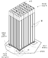
기존의 고밀도 핵연료 저장 랙은 도1에 도시된 바와 같이 받침대 세트 상에서 지지되는 셀(cell)형상 구조물이다. 각 연료 저장셀의 최하단은 위쪽으로 연장되는 저장셀들 및 그 안에 저장된 핵연료에 대한 지지면을 제공하는 역할을 하는 공통 베이스플레이트(baseplate)에 용접된다. 셀 영역은 새로운 또는 사용후 연료를 포함하는 단일 핵연료 집합체를 각각 수용하는 크기인 셀들에 의하여 형성된 협소한 각기둥 형상의 공동(空洞)를 포함한다. '활성 연료 영역'이라는 용어는 농축 우라늄이 위치하는 베이스플레이트 상부의 수직 공간을 일컫는다. 핵연료 랙의 주요 안전 기능은 신뢰할 수 있는 사건-가장 심각한 것은 발전소의 가정된 지진 상황인-하에서 상기 '활성 연료 영역'의 기하학적 구조를 역방향으로 영향 받는 것으로부터 보호하는 것이다. The conventional high-density fuel storage rack is a cell-shaped structure supported on a pedestal set as shown in FIG. The lowermost end of each fuel storage cell is welded to a common base plate that serves to provide support surfaces for upwardly extending storage cells and fuel stored therein. The cell region includes a narrow prismatic cavity formed by cells that are sized to accommodate a single fuel assembly, each containing a new or spent fuel. The term 'active fuel region' refers to the vertical space above the base plate where the enriched uranium is located. The main safety function of the nuclear fuel rack is to protect the geometry of the 'active fuel area' from being affected in the reverse direction under reliable events - the most serious being the assumed seismic conditions of the power plant.
종래의 랙은 4개 또는 그 이상의 받침대를 가진다(예를 들어, 도1 참조). 지진이 발생하면 랙은 바닥 받침대에 상당한 응력을 가하는 캔틸레버 빔(cantilever beam)으로 동작한다. 받침대를 핵연료 저장조의 바닥 콘크리트 슬라브(slab)에 고정시키는 표준 관행은 약 40피트 깊이의 저장조의 물에 잠겨 있는 랙을 제거하는 것을 매우 어렵게 하는 심각한 결점을 가지고 있다. '리랙(rerack)'하는 능력(필요시)과 발전소 직원들에 대한 최소한의 선량(線量)으로 간편하게 폐로(廢爐)하는 것을 고려하여 업계는 '독립형(free-standing)' 구성으로 랙을 설치하였다. 독립형 랙 설계 구성은 지난 30년 동안 전 세계의 발전소에서 사용후핵연료용 습식 저장 용량을 설치하는 지배적인 방법이 되었다. 예상되는 대로, 제조 시설에서 발전소로의 랙 모듈의 운송 및 저장조 내 설치를 위해 발전소 내에서의 랙 모듈 취급의 제약 조건에 의해서만 제한되는 랙 모듈은 가능한 한 크게 만들어진다. 랙 모듈은 또한 소위 '고밀도 구성'에서 가능한 한 근접하게 배치되어 저장조 내 연료 저장 용량을 최대화한다. 인접한 핵연료 랙들 사이의 모듈간 간극은 일부 설치에 있어서 2 인치 정도일 수 있다.Conventional racks have four or more pedestals (e.g., see FIG. 1). When an earthquake occurs, the rack acts as a cantilever beam that gives significant stress to the floor pedestal. The standard practice of securing the pedestal to the bottom concrete slab of a nuclear fuel reservoir has serious drawbacks that make it very difficult to remove the water-immersed rack of the reservoir at about 40 feet deep. Considering that the ability to "rerack" (if necessary) and the ease of dismantling with minimal dose (dose) to plant staff, the industry will set up the rack in a "free-standing" configuration Respectively. Stand-alone rack design configurations have become the dominant method of installing wet storage capacity for spent fuel in power plants around the world for the past 30 years. As expected, the rack modules, which are limited only by the constraints of rack module handling within the plant, are made as large as possible for the transport and storage of the rack modules from the manufacturing facility to the power plant. Rack modules are also positioned as close as possible in so-called 'high-density configurations' to maximize fuel storage capacity in the reservoir. The inter-module clearance between adjacent fuel racks can be as little as two inches in some installations.
독립형 핵연료 랙은 주로 저장조 표면 인터페이스에 대한 받침대에서의 반응 마찰, 소위 유체 결합 효과에 의해 지진 하중에 저항한다. 종래의 독립형 핵연료 랙에서, 받침대는 도1에 도시된 바와 같이 일부 타입의 베어링 패드(bearing pad)상의 핵연료 저장조 바닥 기저 슬라브(bottom base slab) 상에 지지된다. 그러나, 지진이 심한 경우, 인터페이스 마찰은 랙의 측 방향 슬라이딩 이동 또는 기울어짐/뒤틀림을 방지하기에 적절하지 않을 수 있어서, 랙이 충돌하여 셀을 손상시키는 위험을 야기할 수 있고 저장된 핵연료의 물리적 무결성을 손상시킨다.Stand-alone nuclear fuel racks are resistant to earthquake loads primarily by reaction friction in the pedestal to the reservoir surface interface, the so-called fluid coupling effect. In a conventional stand-alone nuclear fuel rack, the pedestal is supported on a fuel base bottom base slab on some types of bearing pads as shown in Fig. However, in the event of severe earthquakes, interface friction may not be appropriate to prevent lateral sliding or tilting / twisting of the rack, which may lead to rack collision and risk of damage to the cell, and physical integrity of the stored fuel .
개선된 내진 핵연료 랙 저장 시스템이 요구된다.An improved seismic nuclear fuel rack storage system is required.
본 발명의 실시의 예들은 랙의 운동을 제한하고 심한 지진 동안 자신의 셀형상 구조 내의 활성 연료 영역에 대한 손상을 방지하고자 하는 핵연료 저장조(pool) 용 내진(高度) 핵연료 랙(rack) 안정화 시스템을 제공한다. 따라서 본 시스템은 예를 들어 지진의 구성 요소 중 '영주기 가속도(zero period acceleration, ZPA)'가 0.5g을 초과하는 경우와 같이 높은 지진 시나리오에서 사용하기 위한 것이다. 본 내진 설계의 실시의 예들의 특징은 상기 랙 모듈은 '독립형' 핵연료 랙을 제공하는 저장조 슬라브(pool slab)에 고정되지 않고 유리하게는 지진 발생 동안 측 방향 수평 이동에 대해 실질적으로 구속되며 모듈의 몸체에 있어서 가장 견고한 위치-베이스플레이트-를 제공하여 지진 하에서 다른 인접 랙들로부터의 충격하중을 흡수하는 범퍼 역할을 한다.Embodiments of the present invention provide a seismic (advanced) fuel rack stabilization system for a nuclear fuel pool that limits the movement of the rack and prevents damage to the active fuel area within its cell structure during severe seismic events to provide. Thus, the system is intended for use in high seismic scenarios, for example when the zero period acceleration (ZPA) of the components of the earthquake exceeds 0.5 g. A feature of embodiments of the present seismic design is that the rack module is not secured to a pool slab providing a 'stand-alone' nuclear fuel rack and is advantageously substantially restrained against lateral lateral movement during an earthquake occurrence, The most rigid position in the body - the base plate - is provided to act as a bumper to absorb impact loads from other adjacent racks under earthquake.
본 발명의 일 실시의 예에 따른 내진(耐震) 핵연료 저장 시스템은 기저 슬라브(base slab) 및 핵연료 습식 저장을 위해 구성된 공동(空洞, cavity)을 집합적으로 정의하는 복수개의 수직 측벽을 포함하는 핵연료 저장조; 복수개의 수직으로 긴 튜브 모양의 셀을 포함하는 핵연료 랙(rack)으로서, 상기 각 셀은 내부에 핵연료를 저장하도록 구성된 각기둥 형상의 공동을 정의하고, 상기 셀은 공통 베이스플레이트(baseplate)에 부착되는, 핵연료 랙; 상기 베이스플레이트로부터 아래로 돌출하는 복수개의 받침대; 및 상기 기저 슬라브에 고정식으로 고정되는 복수개의 이격된 매립 플레이트로서, 각 매립 플레이트는 저장소의 깊이를 정의하는 저장소 벽을 가지는 상향으로 개방된 저장소를 포함하며, 각 저장소는 상기 핵연료 랙의 받침대들 중 하나를 수용하고 포획하는, 매립 플레이트;를 포함하고, 상기 매립 플레이트 저장소는, 지진 발생 시에 상기 핵연료 랙의 상기 기저 슬라브를 따른 측 방향 이동이 각 저장소의 저장소 벽과 상기 받침대 사이의 결합에 의하여 제한되도록 구성된다.A seismic resistant nuclear fuel storage system in accordance with an embodiment of the present invention includes a base slab and a nuclear fuel comprising a plurality of vertical sidewalls collectively defining a cavity configured for wet storage of the nuclear fuel Storage tank; A nuclear fuel rack comprising a plurality of vertically long tubular cells, each cell defining a prismatic cavity configured to store nuclear fuel therein, the cells being attached to a common baseplate , Nuclear fuel rack; A plurality of pedestals projecting downward from the base plate; And a plurality of spaced buried plates fixedly secured to the base slab, each buried plate comprising an upwardly open reservoir having a reservoir wall defining a depth of reservoir, Wherein the buried plate reservoir is adapted to receive lateral movement along the base slab of the nuclear fuel rack upon occurrence of an earthquake by engagement between the reservoir wall of each reservoir and the pedestal .
본 발명의 다른 실시의 예에 따른 핵연료 내진(耐震) 저장을 위한 핵연료 랙(rack) 안정화 시스템은 기저 슬라브(base slab) 및 핵연료의 수중 습식 저장을 위해 구성된 공동(空洞)을 집합적으로 정의하는 복수개의 수직 측벽을 포함하는 핵연료 저장조; 상기 기저 슬라브 상에 지지되는 복수개의 핵연료 랙으로서, 각 핵연료 랙은 수직으로 긴 복수개의 튜브를 포함하고, 각 튜브는 핵연료를 안에 저장하도록 구성된 각기둥 형상의 공동(空洞)을 정의하며, 상기 튜브는 공통 베이스플레이트(baseplate)에 부착되고, 각 핵연료 랙은 상기 베이스플레이트로부터 아래로 돌출하는 이격된 복수개의 받침대를 포함하는, 핵연료 랙; 상기 기저 슬라브에 고정식으로 고정되는 복수개의 이격된 매립 플레이트로서, 각 매립 플레이트는 공동 벽을 가지는 상향으로 개방된 적어도 하나의 매립 공동을 가지며, 각 공동은 그 안의 핵연료 랙들의 각 받침대를 수용하고 포획하는, 매립 플레이트; 및 상기 핵연료 저장조의 기저 슬라브에 고정되고, 상기 복수개의 이격된 매립 플레이트 사이에서 연장되며 상기 매립 플레이트보다 작은 두께를 가지는 저장조 라이너(liner);를 포함하고, 상기 매립 플레이트의 둘레는 매립 플레이트의 모든 측면 주위의 저장조 라이너에 밀폐되게 용접되어 상기 핵연료 저장조로부터의 저장조 물의 외부 누출에 대한 불침투성 장벽을 형성하고, 상기 매립 플레이트 공동은, 지진 발생에 의해 야기되는 상기 기저 슬라브를 따른 상기 핵연료 랙의 측 방향 이동이 측 방향으로 작용하는 지진력이 상기 저장조 라이너로 전달되지 않도록 각 공동의 공동 벽과 받침대 사이의 결합에 의하여 제한되도록 구성된다.A nuclear fuel rack stabilization system for nuclear fuel quake resistant storage according to another embodiment of the present invention is a system for collectively defining a base slab and a cavity configured for underwater wet storage of nuclear fuel A fuel reservoir comprising a plurality of vertical sidewalls; A plurality of fuel racks supported on the base slab, wherein each nuclear fuel rack includes a plurality of vertically long tubes, each tube defining a prismatic cavity configured to store fuel therein, A fuel rack attached to a common base plate, wherein each nuclear fuel rack comprises a plurality of spaced apart pedestals protruding downward from the base plate; A plurality of spaced buried plates fixedly secured to the base slab, each buried plate having at least one buried cavity open upwardly with a cavity wall, each cavity receiving a respective pedestal of nuclear fuel racks therein, A buried plate; And a reservoir liner fixed to the base slab of the fuel reservoir and extending between the plurality of spaced apart buried plates and having a thickness less than that of the buried plate, Wherein the buried plate cavity is welded tightly to a reservoir liner around the sides to form an impermeable barrier to external leakage of the reservoir from the fuel reservoir, Is constrained by engagement between the cavity wall of each cavity and the pedestal so that lateral movement of the lateral movement is not transmitted to the reservoir liner.
본 발명의 또 다른 실시의 예에 따른 핵연료 저장조에서의 핵연료의 내진 저장 방법은 핵 시설에서 제1및 제2 핵연료 랙(rack)을 준비(staging)하는 단계로서, 각 핵연료 랙은 내부에 핵연료를 저장하도록 구성된 각기둥 형상의 공동(空洞, cavity)을 각각 정의하는 복수개의 튜브를 포함하고, 상기 튜브는 베이스플레이트(baseplate)로부터 아래로 돌출하는 복수개의 받침대를 포함하는 공통 베이스플레이트 상에 지지되는, 단계; 기저 슬라브(base slab) 및 상기 기저 슬라브에 고정된 금속 저장조 라이너(liner)를 포함하는 물이 채워진 핵연료 저장조로 상기 제1 핵연료 랙을 낮추는 단계; 및 상기 제1 핵연료 랙의 받침대 각각을 핵연료 저장조의 기저 슬라브에 고정식으로 고정된 복수개의 이격된 매립 플레이트에 형성된 대응하는 상향 개방된 저장소와 삽입가능하게 결합시키는 단계로서, 각 매립 플레이트는 상기 저장조에 밀폐되게 용접되어 상기 핵연료 저장조의 기저 슬라브를 통한 저장조 물의 외부 누출에 대한 불침투성 장벽을 형성하는, 단계;를 포함하고, 상기 매립 플레이트는, 지진 발생 동안 상기 기저 슬라브를 따른 상기 받침대의 측 방향 이동이 측 방향으로 작용하는 지진력이 상기 저장조 라이너로 전달되지 않도록 받침대와 상기 매립 플레이트의 저장소 사이의 결합에 의하여 제한되도록 구성된다.According to another embodiment of the present invention, a method of seismic storage of nuclear fuel in a nuclear fuel storage vessel is a step of staging first and second nuclear fuel racks in a nuclear facility, wherein each nuclear fuel rack contains nuclear fuel A plurality of tubes each defining a prismatic cavity configured to store a plurality of tubes each of which is supported on a common base plate comprising a plurality of pedestals projecting downwardly from a base plate, step; Lowering the first fuel rack with a water-filled fuel reservoir comprising a base slab and a metal reservoir liner secured to the base slab; And inserting each of the pedestals of the first nuclear fuel rack into a corresponding upwardly open reservoir formed in a plurality of spaced buried plates fixedly secured to a base slab of a fuel reservoir, And forming an impermeable barrier against external leakage of the reservoir through the base slab of the fuel reservoir, wherein the burr plate is configured to move laterally of the pedestal along the base slab during an earthquake occurrence, And is constrained by engagement between the pedestal and the reservoir of the buried plate to prevent the lateral force acting on it from being transmitted to the reservoir liner.
또한, 본 발명의 이용 가능한 다른 분야는 이하의 상세한 설명으로부터 명확해질 것이다.Further, other fields that can be utilized by the present invention will be apparent from the following detailed description.
본 발명의 바람직한 실시의 예의 특징들을 유사한 구성요소들은 유사하게 기재되는 하기의 도면들을 참조하여 설명한다.
도1a는 핵연료 저장조(pool)용 종래의 핵연료 저장 시스템의 사시도이다.
도1b는 도1a의 상세도이다.
도2a는 본 발명에 따른 핵연료 저장조 용 핵연료 저장 시스템의 사시도이다
도2b는 도2a의 상세도이다.
도3a는 습식 핵연료 저장 시스템을 형성하는 도2a의 다중 핵연료 랙을 포함하는 핵연료 저장조를 포함하는 핵연료 습식 저장 시스템의 평면도이다.
도3b는 도3a의 상세도이다.
도4는 지진 발생시 핵연료 저장조 내의 2개의 인접한 핵연료 랙 사이의 손상 완화를 위해 구성된 베이스플레이트 에지(edge) 접촉 시스템을 도시한 측단면도이다.
도5는 지진 발생시 핵연료 저장조 내의 2개의 인접한 핵연료 랙 사이의 손상 완화를 위해 구성된 핵연료 랙 지지 레그 또는 받침대 매립 시스템을 도시하는 상세 측입면도이다.
도6은 핵연료 저장조 및 다중 핵연료 랙을 포함하는 핵연료 습식 저장 시스템의 측입면 부분 단면도이다.
도7은 핵연료 랙 받침대의 이동을 측 방향으로 제한하기 위한 본 발명에 따른 제1 매립 플레이트(plate)의 평면도이다.
도8은 제 2 매립 플레이트의 평면도이다.
도9는 제 3 매립 플레이트의 평면도이다.
도10은 도7의 X-X 선에 따른 측단면도이다.
도11은 도 8의 XI-XI 선을 따른 측단면도이다.
도12는 제4 매립 플레이트의 평면도이다.
도13은 핵 조립체의 사시도이다.
도14는 핵연료 랙 지지 받침대 매립 시스템의 대안 배열을 도시하는 상세 측입면도이다.
도15는 핵연료 랙 지지 받침대 매립 시스템의 제2의 대안 배열을 도시하는 상세 측입면도이다.
모든 도면은 개략적이며 반드시 일정한 비율일 필요가 없다. 하나의 도면에서 도시된 및/또는 참조번호가 지정된 부품들은 구체적으로 상이한 참조번호로 지정되고 본 명세서에서 설명되지 않는 한, 간략화를 위해 참조번호의 지정 없이 다른 도면에 나타나는 동일한 부품들로 간주될 수 있다. 본 명세서에서 도면번호(예를 들어, 도1)에 대한 언급은 달리 표시되지 않는 한, 그룹 내의 모든 알파벳 순서의 하위 도면(예를 들어, 도 1a, 1b 등)에 대한 참조로 해석되어야 한다.BRIEF DESCRIPTION OF THE DRAWINGS The features of a preferred embodiment of the invention will be described with reference to the following drawings,
IA is a perspective view of a conventional nuclear fuel storage system for a nuclear fuel pool.
FIG. 1B is a detail view of FIG. 1A.
2A is a perspective view of a nuclear fuel storage system for a nuclear fuel storage vessel according to the present invention
FIG. 2B is a detail view of FIG. 2A.
FIG. 3A is a top view of a nuclear fuel storage system including a fuel reservoir including multiple fuel racks of FIG. 2A, forming a wet fuel storage system; FIG.
FIG. 3B is a detail view of FIG. 3A.
Figure 4 is a side cross-sectional view showing a base plate edge contact system configured for damage mitigation between two adjacent fuel racks in a nuclear fuel reservoir during an earthquake.
5 is a detail side elevation view showing a fuel rack support leg or pedestal landfill system configured for damage mitigation between two adjacent fuel racks in a nuclear fuel reservoir during an earthquake.
Figure 6 is a side elevational partial cross-sectional view of a nuclear fuel storage system including a nuclear fuel reservoir and a multi-fuel rack;
7 is a plan view of a first buried plate according to the present invention for laterally restricting the movement of the nuclear fuel rack.
8 is a plan view of the second embedding plate.
9 is a plan view of the third embedding plate.
10 is a side sectional view taken along the line XX of Fig.
11 is a side sectional view along line XI-XI in Fig.
12 is a plan view of the fourth embedding plate.
Figure 13 is a perspective view of a nuclear assembly.
14 is a detail side elevational view showing an alternative arrangement of a nuclear rack rack support embedding system.
15 is a detail side elevational view showing a second alternative arrangement of the nuclear fuel rack support pedestal embedding system.
All drawings are schematic and do not necessarily have to be a certain percentage. Parts designated and / or numbered in one drawing may be considered the same parts appearing in the other drawings without the designation of reference numerals for the sake of simplicity, unless specifically designated by different reference numerals and described herein have. References herein to a reference numeral (e.g., FIG. 1) should be construed as references to all sub-figures (e.g., FIGS. 1A, 1B, etc.) in alphabetical order within a group unless otherwise indicated.
본 발명의 특징 및 이점은 바람직한 실시의 예들을 참고하여 본 명세서에 도시되고 설명된다. 바람직한 실시의 예들의 설명은 전체 명세서의 한 부분으로 간주되는 첨부된 도면들과 연계하여 해석되도록 한다. 따라서, 본 발명은 단독으로 또는 특징들의 다른 조합으로 존재할 수 있는 특징들의 여러 가능한 비한정적 조합들을 예시하는 이러한 바람직한 실시의 예들로 한정되어서는 명백하게 아니된다. 또한, 본 명세서에 개시된 모든 특징과 설계는 이와 같이 명시적으로 기술되지 않더라도 조합하여 이용될 수 있다.The features and advantages of the present invention are shown and described herein with reference to the preferred embodiments. The description of the preferred embodiments is intended to be interpreted in conjunction with the accompanying drawings, considered as a part of the entire specification. Accordingly, it is not intended that the present invention be limited to such preferred embodiments, which illustrate various possible non-limiting combinations of features that may exist alone or in different combinations of features. Further, all features and designs disclosed herein may be used in combination, even if not explicitly described herein.
본 명세서에 개시되는 실시의 예들의 설명에 있어서, 방향 또는 지향에 대한 어떠한 참조도 단지 설명의 편의를 위함이고 본 발명의 범위를 제한하는 어떠한 방법으로도 의도되어서는 아니 된다. ‘하부의’, ‘상부의’, ‘수평의’, ‘수직의’, ‘위로’, ‘아래로’, ‘위에’, ‘아래에’, ‘상단’ 및 ‘하단’뿐만 아니라 이들의 파생어(예를 들면, ‘수평으로’, ‘아래쪽으로’, ‘위쪽으로’ 등)은 논의된 도면에서 개시되거나 도시된 대로 방향을 참조하는 것으로 해석되어야 한다. 이러한 연관 용어들은 단지 설명의 편의를 위함이고, 장치를 특정 방향으로 구성하거나 작용하는 것을 요구하지 않는다. 명백히 달리 기재되지 않는 한, ‘부착된’, ‘첨부된’, ‘연결된’, ‘결합된’, ‘상호연결된’ 및 유사어는 뗄 수 있거나 견고한 부착 또는 그러한 관계뿐만 아니라 구조물들이 그 구조물들 사이의 개입구조물들을 통하여 직접적으로 또는 간접적으로 서로 고정되고 부착되는 관계를 참조한다. 본 명세서에 기술될 수 있는 임의의 수치 범위는 인용된 범위의 하한 및 상한 수치값 또는 한계를 포함하는 것으로 이해되어야 하고, 인용된 범위에 포함된 임의의 수치값은 한계 값으로서 작용할 수 있음을 이해해야 할 것이다.In the description of the embodiments disclosed herein, any reference to a direction or orientation is for convenience of description only and is not intended to be in any way limiting the scope of the present invention. The terms "lower", "upper", "horizontal", "vertical", "up", "down", "above", "below", "upper" (E.g., "horizontally", "downwardly", "upwardly", etc.) should be interpreted as referring to directions as disclosed or illustrated in the figures discussed. These related terms are merely for convenience of description and do not require that the device be configured or functioned in a particular direction. Unless expressly stated to the contrary, the terms 'attached', 'attached', 'connected', 'coupled', 'interconnected', and the like are intended to encompass both removable or rigid attachment or such relationship, Refer to the relationships that are fixed and attached to each other directly or indirectly through intervening structures. It is to be understood that any numerical range that may be set forth herein should be understood to include lower and upper limit numerical values or limits of the recited range, and that any numerical value included in the recited range may act as a limit value something to do.
도3 및 6을 참고하면, 원자력발전소일 수 있는 핵시설(30)은 본 발명에 따른 복수개의 핵연료 랙(100)을 저장하도록 구성된 핵연료 저장조(pool)(40)를 포함한다. 상기 핵연료 저장조(40)는 인접한 실질적으로 수평인 바닥 기저 벽 또는 슬라브(42)로부터 위쪽으로 상승하는 복수개의 수직 측벽(41)을 포함할 수 있다(상기 저장조가 때로는 그리고 설치공차로 인해 비워지고 씻어내고/오염이 제거되어야 할 경우, 낮은 지점으로의 배수를 위해 일부 경사면은 기저 슬라브의 상부면에 의도적으로 구비될 수 있음을 인식하면서). 상기 기저 슬라브(42) 및 측벽들(41)은 하나의 비 한정적인 실시의 예에서 철근 콘크리트로 형성될 수 있다. 상기 핵연료 저장조 기저 슬라브(42)는 상면이 등급G를 규정하는 토양 지반(26)에 형성될 수 있고 그 위에 놓일 수 있다. 본 출원에 예시된 실시의 예에서, 측벽은 등급 이상으로 상승된다. 상기 기저 슬라브(42)는 도시된 바와 같이 등급 G, 등급 이하 또는 등급 이상으로 위치될 수 있다. 고려될 수 있는 다른 가능한 실시의 예에서, 상기 기저 슬라브(42)와 측벽들(41)은 측벽들의 외면들을 둘러싸는 토양 지반(26)에 대안적으로 매립될 수 있다. 전술한 배열 또는 다른 배열이 핵시설의 배치에 따라 사용될 수 있으며 본 발명을 제한하지 않는다.3 and 6, a nuclear facility 30, which may be a nuclear power plant, includes a
일 실시의 예에 있어서, 핵연료 저장조(40)는 평면도에 있어서 직선형상을 가질 수 있다. 저장조가 2개의 보다 긴 마주보는 측벽과 2개의 보다 짧은 마주보는 측벽 (예를 들어, 단부 벽)을 갖는 긴 직사각형 형상 (평면도 상에서)을 갖는 4개의 측벽(41)이 제공 될 수 있다. 정사각형 형상, 다른 다각형 형상 및 비 다각형 형상과 같은 핵연료 저장조(40)의 다른 구성이 가능하다.In one embodiment, the
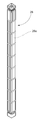
상기 핵연료 저장조(40)의 측벽(41) 및 기저 슬라브(42)는 냉각 저장조 물(W) 및 각각이 다수의 핵연료다발 또는 집합체(28)(도13에 전형적인 것이 도시됨)를 담고 있는 복수개의 수중 핵연료 랙(100)을 담도록 구성된 위로 개방된 우물 또는 공동(cavity, 空洞)(43)을 정의한다. 각 핵연료 집합체(28)는 다수의 개별적인 새로운 또는 사용된 우라늄 연료봉(28a)을 포함한다. 핵연료 집합체는 출원 내용 모두가 참조로서 본 출원에 포함되는 2013년 7월 9일에 출원된 공동 양도된 미국 특허출원 14/367,705에 추가로 설명되어 있다. 가압수형 원자로(PWR)에 대한 통상적인 핵연료 집합체(28)는 집합체 당 10Х10 내지 17Х17 핵연료봉 격자배열로 150개 이상의 연료봉을 각각 보유할 수 있다. 상기 집합체는 통상적으로 각각 약 1400 내지 1500 파운드 무게로 약 14피트 높이일수 있다. 상기 핵연료 집합체를 저장하는 상기 핵연료 랙(100)은 본 명세서에서 추가로 기술된 바와 같이 수평으로 맞닿는 방식으로 고밀도 배열로 상기 기저 슬라브(42)상에 설치된다.The
상기 핵연료 저장조(40)는 핵연료 저장조(40)를 둘러싸는 작동 데크(deck)(22)로부터 아래방향으로 충분한 수직 깊이 D1까지 연장되어 적절한 방사선 차폐 목적으로 핵연료 랙에서 연료집합체(28)를 저장조 물(W)의 표면 수위S 아래로 잠근다(예를 들어, 도6 참조). 일 실시의 예에서 측벽(41) 및 저장조(40)의 모든 면을 둘러싸는 실질적으로 수평인 작동 데크(22)는 강철 및/또는 철근 콘크리트로 형성될 수 있다. 일 실시의 예에서, 핵연료 저장조는 적어도 10피트의 물이 핵연료 집합체의 상단 위에 존재할 수 있는 깊이를 가질 수 있다. 저장조와 저장조 물의 다른 적절한 깊이는 물론 사용될 수 있다. 저장조(40)내의 저장조 물(W)(예를 들어, 액체 냉각제)의 표면 수위는 핵연료 집합체 적재 하역 작업 중 및 지진발생으로 인한 데크로의 유출을 방지하기에 충분한 양으로 작동 데크(22) 아래에서 이격될 수 있다. 하나의 비 한정적 실시의 예에서, 예를 들어, 작업 데크(22)의 표면은 일 실시의 예에서의 해당 사이트에 대한 최대 100년 홍수 수위보다 적어도 5피트 위일 수 있다. 작동 데크 높이 아래로 연장되는 상기 핵연료 저장조(40)는 대략 40피트 또는 그보다 깊을 수 있다 (예를 들어, 일 실시의 예에서 42피트). 상기 핵연료 저장조는 필요한 만큼의 핵연료 랙(100) 및 여기에 저장된 핵연료 집합체(28)를 수용할 만큼 충분히 길고 넓다. 저장조 주위에 작동 데크 공간이 충분히 있어서 작업자들을 위한 공간 및 시설 유지 보수에 필요한 도구와 장비를 집결시키기 위한 공간을 제공한다. 돌발적인 물의 배수 및 연료의 노출을 방지하기 위해 바닥 30피트 깊이 이내의 핵연료 저장조(40)에는 침투가 없을 수 있다.The
일부 실시의 예에서, 핵연료 저장조 라이너(liner) 시스템은 환경으로의 저장조 물 누출의 위험을 최소화하기 위해 제공될 수 있다. 상기 라이너 시스템은 냉각수 누출 집진 및 검출/모니터링을 포함하여 라이너 시스템의 무결성 파괴로 야기되는 누출 상태를 나타낸다. 라이너 시스템은 출원 내용 모두가 참조로서 본 출원에 포함되는 2015 년 10 월 7 일에 출원된 공동 소유된 미국 특허출원 14/877,217에 추가로 설명되어 있다.In some embodiments, a nuclear fuel liner system may be provided to minimize the risk of leaking water to the environment. The liner system represents a leaking condition resulting from the integrity failure of the liner system, including cooling water leakage dust collection and detection / monitoring. The liner system is further described in commonly owned U. S. Patent Application Serial No. 14 / 877,217, filed October 7, 2015, the entire contents of which are incorporated herein by reference.
일 실시의 예에서 라이너 시스템은 핵연료 저장조 측벽(41) 및 기저 슬라브(42)의 내부면(63)에 부착된 라이너(60)를 포함할 수 있다. 라이너의 내부면(63)은 핵연료 저장조 물(W)에 접촉되고 습윤된다. 상기 라이너(60)는 비 제한적 예를 들어 스테인리스 강, 알루미늄 또는 그 외 다른 것들을 포함하는, 바람직하게 부식에 강한 적절한 두께(T2)의 임의의 적합한 금속으로 제조될 수 있다. 전형적인 라이너의 두께(T2)는 대략 3/16 인치 내지 5/16 인치 사이일 수 있다. 전형적인 스테인리스 강 라이너 플레이트(plate)는 ASTM 240-304 또는 304L을 포함한다.In one embodiment, the liner system may include a
일부 실시의 예에서, 상기 라이너(60)는 연속된 주변 가장자리를 따라 밀봉용접을 통해 함께 밀폐되게 용접되어 상기 핵연료 저장조(40)의 측벽과 기저 슬라브(42)를 완전하게 캡슐화(encapsulate)하고 저장조 물(W)이 빠져 나가는 것을 방지하는 연속 라이너 시스템을 형성하는 다수의 실질적으로 평평한 금속판들 또는 섹션들로 이루어질 수 있다. 상기 라이너(60)는 상기 핵연료 저장조(40)의 수직 측벽(41)을 따라 그 주위로 그리고 수평 기저 슬라브(42)를 완전히 가로 질러 연장되어 저장조의 습윤 표면 영역을 완전히 덮는다. 이는 상기 라이너의 수평부분(60b) 및 수직부분(60a)을 형성하여 핵연료 저장조(40)로부터 저장조 물(W)의 외부 누출에 대한 불침투성 장벽을 제공한다. 상기 기저 슬라브(42)상의 라이너(60b)의 수평부분은 상기 수직부분(60a)에 이들 사이의 둘레 모서리 이음새를 따라 밀폐 밀봉 용접에 의해 결합될 수 있다. 상기 라이너(60)는 체결구와 같은 임의의 적합한 방법에 의해 상기 핵연료 저장조(40)의 기저 슬라브(42) 및 측벽(41)에 고정식으로 고정될 수 있다.In some embodiments, the
도2 내지 6을 참조하면, 본 발명의 일 실시의 예에 따른 핵연료 랙(100)의 사시도가 개시된다. 상기 핵연료 랙(100)은 셀(cell)형상의 직립형 프리즘 형상의 모듈이다. 상기 핵연료 랙(100)은 인접한 셀들(110) 사이에 중성자 선속 트랩의 존재를 요구하지 않는 핵연료 집합체와 함께 사용되도록 설계된, 도시된 바와 같이 고밀도의 단단히 다져진 비-선속 타입의 랙일 수 있다. 따라서, 소중한 핵연료 저장조 바닥 영역이 불필요하게 낭비되기 때문에, 필요하지 않을 때 핵연료 랙에 중성자 선속 트랩을 포함(예를 들면, 간극)하는 것은 바람직하지 않다. 물론, 비-선속 및 선속 핵연료 랙 유형 모두는 본 발명에 따른 내진 핵연료 저장 시스템을 이용하여 동일한 저장조에 나란히 저장 될 수 있다. 따라서, 본 발명은 임의의 특정 유형의 랙의 사용에 있어서 제한되지 않는다.Referring to Figures 2 to 6, a perspective view of a
핵연료 랙(100)은 수직 길이방향 축(LA)을 정의하고 서로 평행한 축 관계로 배치된 복수개의 인접한 긴 튜브(120)에 의해 형성된 밀집된 개방 셀(110)의 격자 배열을 포함한다. 랙은 핵연료 랙의 둘레를 정의하는 주변에 배치된 외측 튜브 (120A) 및 상기 외측 튜브들 사이에 위치한 내측 튜브(120B)를 포함한다. 상기 튜브들(120)은 그들의 하단부(114)에서 베이스플레이트(baseplate)(102)의 평평한 상면에 결합되고 그로부터 실질적으로 수직 방향으로 상향 연장된다. 이 실시의 예에서, 각 튜브(120)의 수직 또는 중심 축은 실질적으로 수직일 뿐만 아니라 상기 베이스플레이트(102)의 상면에 실질적으로 수직이다. 일 실시의 예에서, 상기 튜브(120)는 용접 및/또는 볼트로 조이기, 클램프(clamp)로 조이기, 나사가공 등과 같은 기계적 결합에 의하여 베이스플레이트(102)에 고정될 수 있다.
상기 튜브(120)는 상단부(112), 하단부(114) 및 높이(H1)를 정의하는 단부들 사이의 길이 방향으로 연장되는 복수개의 수직 측벽(116)을 포함한다. 각 튜브(120)는 상단부 및 하단부(112, 114) 사이에서 길이 방향으로 연장되는 내부 공동(118)을 정의한다. 도2a 내지 도2b에 도시된 실시의 예에서, 직선형 다각형 관계로 배열된 4개의 튜브 측벽(116)이 구비되어 평면도 또는 수평도에서 횡단면 또는 가로지르는 단면(즉, 길이방향 축(LA)에 횡단 또는 직각)으로 정사각형 또는 직사각형 튜브(120)를 형성한다(또한 도3 참조). 따라서, 셀(110) 및 내부 공동(118)은 횡단면에서 대응하는 직사각형 구성을 가진다. 상기 튜브(120)의 상단부는 개방되어 핵연료 집합체가 튜브 측벽(116)의 내면에 의해 형성된 내부 공동(118) 내로 미끄러져 내려갈 수 있다. 각 셀(110) 및 그 공동(118)은 단일 핵연료 집합체(28)만을 보유하도록 구성된다.The
각 튜브(120)는 원하는 전체 높이(H1)를 연장시키는 하나의 단일 구조적 구성 요소로서 형성될 수 있거나, 수직으로 적층되고 용접 또는 원하는 높이(H1)까지 집합적으로 합하는 기계적 수단에 의해 함께 연결되는 다수의 부분 높이 튜브들로 구성될 수 있음은 명확하다. 상기 튜브(120)의 높이(H1)는 핵연료 집합체가 튜브에 삽입될 때 상기 핵연료 집합체의 전체 높이가 튜브 내에 포함될 수 있도록 충분한 것이 바람직하다. 상기 튜브(120)의 상단부(112)는 바람직하게는 하지만 반드시 그런 것은 아니지만 실질적으로 동일한 수평면(길이방향 축(LA)에 수직으로 정의되는)에서 끝날 수 있어서 튜브의 상단들은 서로 수평을 이룬다. 상기 튜브의 하단부(114)에 있는 상기 베이스플레이트(102)는 제2수평 기준면(HR)을 정의한다.Each
도2a 내지 도2b에 가장 잘 도시된 바와 같이, 상기 튜브들(120)은 Z축 및 X축을 따라 행 및 열로 베이스플레이트(102) 위에 기하학적으로 각각 배열된다. 저장조 기저 슬라브(42)의 수평 길이 및 폭 과 구비될 핵연료 랙(100)의 개수에 따라, 각 행 및 열에서 동일하거나 동일하지 않은 개수의 튜브를 포함하는 임의의 적절한 배열의 크기가 제공될 수 있다. 일부 실시의 예에서, 상기 핵연료 랙(100)의 일부 또는 모두는 각 설치에 대해 이용 가능한 슬라브 표면적의 양을 가능한 최대한 활용할 수 있도록 동일하지 않은 측면 폭 및 측면 길이를 가질 수 있다.As best seen in FIGS. 2A-2B, the
참조의 편의를 위해, 상기 외측 튜브(120A)의 외향 측벽(116)은 도1 내지 도2에 도시된 바와 같이 랙 둘레 주위로 연장되는 상기 핵연료 랙(100)의 복수개의 측면(130)을 집합적으로 정의하는 것으로 간주될 수 있다.For convenience of reference, the
상기 튜브(120)는 핵연료 저장 랙에서 이용 가능한 임의의 적합한 소재로 구성될 수 있다. 일 실시의 예에서, 제한 없이, 상기 튜브는 금속 매트릭스 복합 소재, 바람직하게는 불연속적으로 강화된 알루미늄/붕소 카바이드 금속 매트릭스 복합 소재, 보다 바람직하게는 붕소 함침 알루미늄으로 형성될 수 있다. 하나의 이러한 적합한 소재는 상표명 MetamicTM하에 판매된다. 상기 튜브(120)는 구조적 지지뿐만 아니라 반응성 제어의 이중 기능을 수행한다. 유리하게는, 중성자 흡수재를 포함하는 튜브 소재는 상기 튜브 측벽(116)의 더 작은 단면(즉, 길이 방향 축(LA)에 대해 측 방향 또는 가로지르는) 두께를 허용하여, 셀이 더욱 단단히 다져지게 되어 핵연료 랙 당 더 많은 수의 셀이 제공되도록 한다. 상기 베이스플레이트(102)는 바람직하게는 용접이 용이하도록 상기 튜브(120)가 구성되는 소재와 야금학적으로 호환 가능한 금속으로 구성된다.The
도2 내지 6(모든 알파벳 하위 항목을 포함하는)을 참조하면, 각 핵연료 랙(100)은 상기 핵연료 저장조(40)의 기저 슬라브(42)로부터 랙을 지지하는 복수개의 레그(leg) 또는 받침대(200)를 포함한다. 상기 받침대(200) 각각은 바람직하게 평평한 하단부(204)를 포함하여 상기 저장조 기저 슬라브(42)와 상기 베이스플레이트(102)의 바닥에 고정식으로 부착된 상단부(202)를 맞물리게 한다. 상기 받침대(200)는 상기 베이스플레이트(102)로부터 아래로 돌출한다. 이는 상기 랙의 베이스플레이트(102)를 상기 기저 슬라브(42)로부터 들어 올림으로써 상기 랙(100) 아래의 바닥 유동 플리넘(plenum, P)을 정의하는 간극을 상기 기저 슬라브들(42) 사이에서 형성할 수 있다. 상기 플레넘(P)은 저장조 내의 냉각수(W)로 하여금 각 핵연료 저장 튜브(120)를 통해 자연 대류 순환 유로를 생성하게 한다(예를 들어, 도5의 유동 방향 화살표 참조). 냉각수가 각각의 튜브(120)의 공동(118)을 통해 위쪽으로 그리고 튜브의 개방된 상단부(112)를 통해 바깥쪽으로 흐를 수 있도록 하는 종래의 방식으로 복수개의 유동 홀(hole, 115)이 상기 베이스플레이트(102)를 통해 랙에 형성된다. 2014년 6월 20일에 출원된 공동 소유의 미국 특허출원 14/367,705는 유동 홀을 가지는 핵연료 랙 베이스플레이트를 도시하며, 출원 내용 모두가 참조로서 본 출원에 포함된다. 상기 튜브를 통해 흐르는 저장조 물(W)은 상기 핵연료 집합체의 핵연료에 의해 가열되어 자연 대류 흐름을 유도하는 원동력을 생성할 수 있다.Referring to Figures 2-6 (including all alphabetic sub-items), each
이제 도3 및 도5를 참조하면, 상기 유동 홀(115)은 상기 베이스플레이트(102) 아래에서 상기 튜브(120)에 의해 형성된 셀(110)로 통로를 생성한다. 바람직하게는, 단일 유동 홀(115)이 각각의 셀(110)에 구비되지만, 필요에 따라 더 많은 유동 홀이 이용되어 상기 튜브를 통해 충분한 유동을 생성할 수 있다. 상기 유동 홀(115)은 유입구로서 구비되어, 열 부하를 가지는 핵연료 집합체가 내부에 위치할 때 상기 셀(110)을 통한 저장조 물의 자연적인 열 사이펀(thermosiphon) 흐름을 용이하게 한다. 보다 구체적으로, 잠수된 환경에서, 가열된 핵연료 집합체가 셀(110) 내에 배치되면, 상기 핵연료 집합체를 둘러싸고 있는 셀(110) 내의 물이 가열되어, 밀도의 감소 및 상승된 부력으로 인해 상승하여 자연스러운 상향 유동 패턴을 생성한다. 이 가열된 물이 상승하여 튜브 개방 상단부(112) 를 통해 셀(110)을 거쳐 배출될 때(도1 참조), 냉각수는 상기 유동 홀(115)을 통해 셀의 바닥으로 유입된다. 이 가열 유도된 물의 흐름 및 핵연료 집합체를 따른 순환 패턴은 자연적으로 계속해서 핵연료 집합체에 의해 생성된 열을 방출한다.Referring now to FIGS. 3 and 5, the
따라서, 상기 받침대(200)는 충분한 열적 유도 순환이 생성되어 상기 핵연료 집합체를 적절히 냉각시키는 것을 보장하는 일반적으로 상응하는 높이의 바닥 흐름 플리넘(P)을 형성하도록 선택된 높이(H2)를 가질 수 있다. 하나의 비 한정적인 예에서, 상기 플리넘(P)의 높이(H2)는 약 2 내지 2.5 인치(inch)일 수 있다(상기 열거된 범위 및 이 범위 사이의 값들을 포함).Thus, the
받침대(200)는 임의의 적합한 구성 또는 형상을 가질 수 있고 임의의 적절한 유형일 수 있다. 이용될 수 있는 형상의 일부 비 한정적인 예는 직선형 횡단면/가로지르는 단면 형상을 갖는 직사각형 또는 정사각형, 원형 단면 형상을 갖는 원통형, 다각형 단면 형상을 갖는 다각형, 비 다각형 단면 형상을 갖는 비 다각형 또는 이들의 조합일 수 있다. 도1에 도시된 하나의 조합은 핵연료 랙 베이스플레이트(102)에 부착된 직사각형 상부 및 안정된 방식으로 핵연료 저장조(40)를 결합시키기 위한 원형의 원통형 발판을 형성하는 확대된 원통형 디스크 형상의 하부를 포함하는 고정된 높이의 받침대이다. 도2a 및 도2b는 본 명세서에서 추가로 설명된 바와 같이 조절 가능한 받침대(200)를 도시한다. 도4 및 도5는 앞서 언급한 형상들 또는 기타 중 임의의 것을 가질 수 있는 고정 높이 받침대(200)를 도시한다.The
본 발명에 따른 내진 핵연료 랙 저장 시스템에 대해 본 명세서에서 기술된 받침대(200)는 배경기술에서 설명된 바와 같이 '독립형' 핵연료 랙(100) 용으로 구성된다는 것에 유의해야 한다(즉, 상기 받침대와 핵연료 랙을 상기 핵연료 저장조 바닥에 고정시키는 체결구 제공에 이용되는 홀과 같은 제공은 없음).It should be noted that the
상기 받침대(200)는 바람직하게는 적절한 치수 및 두께의 내(耐)부식성 금속으로 제조되어 상기 베이스플레이트(102)에 의해 지지되는 상기 핵연료 집합체(28) 및 저장 튜브(120)의 무게를 적절히 지지하는데 필요한 강도를 제공한다. 각 핵연료 랙(100)은 상기 베이스플레이트(102)의 주변 가장자리 및 둘레를 따라 이격되어 배치된 복수개의 주변 받침대(200)를 포함할 수 있고, 내측 핵연료 집합체 및 튜브(120B)를 보충적으로 지지해야 할 필요가 있다면, 선택적으로 하나 이상의 내부 받침대를 포함할 수 있다. 하나의 비 한정적인 실시의 예에서, 각각 상기 베이스플레이트의 4개의 모서리(206) 중 하나에 근접하여 위치하는 4개의 주변 받침대(200)가 구비될 수 있다. 필요에 따라 상기 베이스플레이트 주변의 모서리 받침대 사이에 추가적인 주변 받침대가 물론 구비될 수 있다. 상기 받침대는 바람직하게는 각 핵연료 랙 또는 모듈의 베이스플레이트(102)의 주변 가장자리(208)에 인접하여 가능한 한 외부에 위치하여 모듈에 최대의 회전 안정성을 부여한다.The
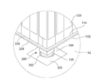
도2 내지 도6을 계속 참조하면, 내진 핵연료 저장 랙 시스템은 상기 핵연료 랙 받침대(200)와 결합하기 위해 핵연료 저장조(40)의 기저 슬라브(42)에 고정식으로 결합된 복수개의 특별히 구성된 매립 플레이트(plate)(300)를 더 포함한다. 따라서, 상기 매립 플레이트(300)는 상기 기저 슬라브(42) 또는 저장조 라이너(60)과 인접한 저장조와 관련하여 움직일 수 없다. 상기 매립 플레이트(300)는 상기 저장조 기저 슬라브(42) 둘레로 측 방향으로 이격된 패턴으로 배열되고, 각각은 상기 핵연료 랙 받침대(200)들 중 적어도 하나의 위치와 일치하도록 위치된다. 이것은 어떤 실시의 예에서는 두 개의 매립 플레이트(300)가 서로 접촉하지 않는 불연속 받침대 지지 시스템을 형성한다. 일 실시의 예에서 상기 저장조 라이너(60)는 산재되어 있으며 매립 플레이트들 사이에서 연장된다. 상기 매립 플레이트(300) 각각은 모든 방향으로 상기 핵연료 랙(100) 또는 라이너의 섹션보다 적은 측면 치수를 가진다.2 to 6, the seismic nuclear fuel storage rack system includes a plurality of specially configured landfill plates (not shown) coupled rigidly to the
측 방향으로 이격된 매립 플레이트(300)들 각각은 도5에 도시된 바와 같이 모든 주변 측면을 따라 밀봉용접부(140)를 거쳐 함께 밀폐되게 용접되어 상기 핵연료 저장조(40)의 기저 슬라브(42)를 완전하게 캡슐화하는 연속 밀폐 라이너 시스템을 형성한다. 일 구성에 있어서, 상기 매립 플레이트(300)는 도5에 도시된 바와 같이 상기 저장조 라이너(60)의 인접 부분의 상면(바닥 F)을 넘어서 위쪽으로 돌출하여 상기 라이너에 대한 매립 플레이트의 전체 둘레 주위에 필릿(fillet) 용접을 형성하는 것을 용이하게 한다. 기타 배열 및 용접 유형이 가능하다. 따라서, 밀봉용접된 상기 매립 플레이트(300) 및 라이너(60)의 하부 부분은 핵연료 저장조(40)로부터 기저 슬라브를 통한 저장조 물(W)의 외부 누출에 대한 불침투성 장벽인 저장조 바닥을 집합적으로 형성한다.Each laterally spaced buried
상기 매립 플레이트(300)는 상면을 정의하는 바람직하게 평평한 상부벽(212)을 포함하고, 받침대(200) 및 매립 플레이트 위에 안착된 상기 핵연료 랙의 총 중량의 일부분을 지지하기에 적절한 두께를 가진다. 예시된 바람직한 매립에 있어서, 상기 매립 플레이트들(300)은 바람직하게는 상기 라이너(60)와 독립적으로 그리고 그 사이에 임의의 개입 구조(도4 및 도5에 가장 잘 도시됨)없이 상기 핵연료 저장조(40)의 기저 슬라브(42)에 고정식으로 부착되고 직접 고정된다. 상기 매립 플레이트(300)와 상기 저장조 라이너(60) 또는 기저 슬라브(42) 사이에는 상대적인 이동이 없다. 이는지진 발생(예: 지진) 중에 저장조의 기저 슬라브(42)에 대한 상기 매립 플레이트(300)의 최적의 고정 및 안정화를 보장하여 상기 매립 플레이트가 상기 기저 슬라브 또는 라이너(60)에 대해 미끄러지거나 움직일 수 없도록 한다. 이는 또한 측 방향 또는 수직방향 힘을 상기 라이너(60)에 전달하지 않고 상기 라이너(60)의 무결성에 악영향을 미치지 않으면서 지진 발생에 의해 생성된 수평 방향의 측 방향 힘(F1)과 완전히 채워진 핵연료 랙(100)의 수직 중량이 상기 핵연료 저장조(40)의 강심(鋼心)(예를 들어, 철근(rebar)) 기저 슬라브(42)에 직접 전달되는 것을 보장한다. 이는 상기 라이너(60)가 상기 매립 플레이트(300)보다 얇게 되도록 하며 상기 라이너(60)가 저장조 물 격납고(pool water containment)의 무하중 지지 기능만을 위해 설계되도록 한다. 상기 매립 플레이트(300)의 구조적 특성 및 하중 지지 기능으로 인해, 상기 플레이트는 바람직하게는 예를 들어 두께(T2)의 적어도 2배와 같이 상기 저장조 라이너(60)의 두께(T2보다 실질적으로 큰 두께(T1)를 가진다)(도5 참조). 상기 매립 플레이트(300)는 1인치 이상의 최소 두께를 가질 수 있다.The buried
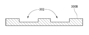
각 매립 플레이트(300)는 바닥(351) 및 수직 연장 측벽(352)을 포함하는 상보 적으로 구성된 상향 개방 고정 리세스(recess)(350)에 수용될 수 있다. 상기 리세스(350)의 바닥 및 측벽 상의 핵연료 저장조의 콘크리트 기저 슬라브(42)의 소재가 매립 플레이트의 바닥 및 측면과 밀접한 등각 접촉을 하도록, 등각 맞춤(conformal fit)이 가능하면 바람직하게 상기 매립 플레이트(300)와 고정 리세스(350) 사이에서 제공된다(예를 들어, 도5 참조). 이는 상기 기저 슬라브 용 콘크리트가 부어지기 전에 상기 매립 플레이트(300)가 설치되거나 상기 플레이트의 측면과 약간 확장된 리세스의 측벽(352) 사이의 플레이트(300)의 둘레 주변의 간극에 콘크리트 회반죽(grout)이 추가되면 쉽게 달성될 수 있다. 이들 구성 시나리오들 중 어느 하나에 있어서, 측 방향 및 수평 방향으로 작용하는 지진 하중 또는 이동 받침대(200)와 (이하에 설명된) 매립 공동(302)의 측벽(204)들 사이의 결합에 의해 생성된 매립 플레이트에 작용하는 힘(F1)은 저장조 라이너 시스템의 누출 방지 무결성을 훼손하거나 손상시킬 수 있는 보다 얇고 구조적으로 덜 튼튼한 저장조 라이너(60)에 전달되지 않고, 상기 매립 플레이트(300)의 측면과 접촉하는 슬라브의 수직 측벽(352)를 거쳐 측 방향으로 기저 슬라브(42)에 직접 전달된다. Each buried
대안적으로 일부 실시의 예에서, 상기 기저 슬라브(42)가 부어진 후 상기 매립 플레이트(300)가 추가되고 주변 콘크리트 회반죽이 상술한 바와 같이 첨가되지 않으면, 최소의 감지 가능한 간격이 바람직하게는 상기 매립 플레이트(300)의 측면과 리세스(350)의 측벽(352) 사이에 제공되어 본 명세서의 다른 곳에 기술된 주변 밀봉용접부(140)가 상기 플레이트와 저장조 라이너(60) 사이에서 형성되는 것을 허용한다. 추가적으로, 도14에 도시된 것과 유사하고 본 명세서에 추가로 기술된 하나 이상의 관통 앵커(anchor)(400)(현재 도5에서 점선으로 표시된)는 상기 고정 리세스(350)의 바닥(351)을 통해 상기 매립 플레이트(300)를 상기 매립 플레이트 하부의 콘크리트 기저 슬라브(42)로 고정시키기 위하여 추가되어야 한다. 이러한 구성에서의 측 방향으로 작용하는 지진 하중 또는 힘(F1)은 상기 매립 플레이트(300)로부터 앵커(400)를 통해 상기 기저 슬라브(42)로 전달되어 이들 지진력 중 어느 것도 상기 라이너 시스템의 무결성을 보호하기 위해 보다 얇은 저장조 라이너(60)에 전달되지 않는다.Alternatively, in some embodiments, if the buried
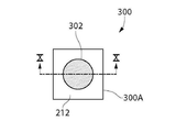
상기 랙 및 핵연료 저장 튜브(120)에 손상을 줄 수 있는 지진이 발생하는 동안 인접한 핵연료 랙(100)들 사이의 미끄럼 결합 및 충돌 하중을 최소화하기 위해, 각각의 매립 플레이트(300)는 상기 핵연료 랙(100)의 받침대(200)를 포획하여 결합하도록 구성된 적어도 하나의 움푹 패인 가공된 저장소 또는 공동(302)을 포함한다. 각 매립 공동(302)은 받침대(300)의 말단 하단부(204)를 수용하고 인접하게 맞물려 지진 발생 동안 받침대의 측 방향/수평 방향 이동을 제한하도록 구성(즉, 형상화 및 치수화)된다. 이는 도4 및 도5에 가장 잘 도시되어 있다. 각 공동(302)은 상기 받침대(200)의 하단부와 결합하기 위한 수직 상향 대향 수평 지지면을 정의하는 평평한 바닥벽(306)과 이로부터 상향으로 직각으로 연장되며 받침대의 측면과 결합하기 위한 내측 대향 수직 지지면을 정의하는 복수개의 바람직하게 평평한 측벽(304)에 의하여 집합적으로 정의된다. 상기 공동(302)들은 상기 핵연료 저장조(40)에 설치되는 경우 상기 핵연료 랙(100)의 받침대(200)를 수용하기 위한 개방 상부를 가진다.In order to minimize the sliding engagement and impact loads between
바람직하게는, 상부벽(212)의 일부 및 표면이 모든 면에서 공동을 완전히 제한하고 둘러싸도록(예를 들어 도4 내지 5 및 도7 내지 12 참조), 각 매립 플레이트 공동(302)은 상기 매립 플레이트(300)의 중심 영역에 위치될 수 있다. 이러한 배열은 공동 (302)를 둘러싸는 매립 플레이트(300)의 부분이 지진 발생 동안 슬라이딩 받침대(200)에 의한 충격으로 인해 수평 방향으로 공동의 측벽(304)에 작용하는 측 방향 충격력을 견딜 수 있는 적절한 구조적 강도를 갖는 것을 보장한다.Preferably, each of the buried
각 매립 플레이트 공동(302)은 공동의 경계 내에서 받침대(200)의 충분한 하부 부분을 수용하고 이를 포획 또는 구속하도록 선택되는 깊이(D2)를 가진다. 적절한 공동 깊이(D2)는 한편으로는 받침대를 가능한 한 짧게 유지하려는 경쟁적 관심사의 무게를 측정하여 선택되어 지진 발생시 받침대에 부여된 캔틸레버(cantilevered) 굽힘 모멘트에 저항할 수 있으며(받침대의 하부 부분이 저장조 라이너(60)의 상부면에 의해 정의된 저장조 바닥의 바닥(F) 아래의 매립 플레이트 공동내에서 연장됨을 인식하면서), 다른 한편으로는 적절한 높이의 바닥 유동 플리넘(P)을 유지하여 선택되어 핵연료 랙(100)를 통해 필요한 양의 자연 열 저장조 물 순환을 유도하여 핵연료를 냉각시킨다. 상기 깊이(D2)는 또한 지진 발생으로 인해 야기된 진동 동안 상기 받침대(200)가 공동으로부터 '튀어 나오지' 않도록 충분히 깊어야 한다. 하나의 비 한정적인 예에서, 상기 매립 공동(302)의 깊이(D2)는 바람직하게는 약 1 내지 3인치(inch), 보다 바람직하게는 약 1 내지 2인치, 가장 바람직하게는 약 1 내지 1.5인치일 수 있다(나열된 값 및 이들 범위 사이의 값들을 포함함).Each buried
각 매립 플레이트 공동(302)은 받침대(200)의 가로지르는 단면 또는 횡단면 형상에 상보적인 구성을 더 가진다. 각 공동(302)은 바람직하게는 받침대의 유사한 폭 또는 직경보다 측 방향 또는 수평 치수에 있어서 최소한도로 더 커서 상기 받침대 그리고 따라서 전체 핵연료 랙(100)에 허용된 측 방향 이동량을 최소화한다. 상기 공동(302) 내에 맞는 받침대(200) 하부의 최대 가로지르는 단면 치수는 가로지르는 폭(W2) 또는 직경(D3)이 상기 하부의 모양(예를 들어, 직선, 다각형, 원형 등)에 따라 적용 가능한 것으로 정의하는 것으로 고려될 수 있다. 사용된 명명법은 중요하지 않으며 단지 이 최대 가로지르는 치수를 설명한다. 비슷한 맥락에서, 매립 공동(302)의 가로지르는 단면 형상에 따라, 상기 공동은 가로지르는 폭(W3) 또는 직경(D4)을 가지는 것으로 정의될 수 있다. 일 실시의 예에서, 바람직하게는 제한 없이 공동(302)은 받침대(200)의 최대 가로지르는 단면 치수(예를 들어, 폭(W2) 또는 직경(D3))보다 단지 5% ~ 50%(이들 백분율을 포함하거나 그 사이의 백분율을 포함), 더욱 바람직하게는 단지 10% ~ 30% 큰 최대 가로지르는 단면 치수(예를 들어, 폭(W3) 또는 직경(D4))를 가질 수 있다. 다른 방법을 고려하면, 매립 공동(302)의 측벽(304)과 받침대(200) 사이에 형성된 물리적 고리모양의 유격 또는 간극(G1)(받침대의 하부부분의 최대 가로지르는 단면 치수로부터 측벽까지 측정된)은 바람직하게는 단지 0.5 ~ 4인치(inch)(이들 거리를 포함하거나 그 사이에 이들 거리를 포함), 더욱 바람직하게는 단지 0.5 ~2인치일 수 있다. 바람직하게는, 상기 간극(G1)은 받침대(200)의 최대 가로지르는 단면 치수(W2/D3)의 1/2 보다 적으며, 더욱 바람직하게는 1/3보다 적으며, 가장 바람직하게는 받침대(200)의 최대 가로지르는 단면 치수의 1/4보다 적다. 상기 핵연료 저장조(40)로부터 핵연료 랙을 설치하거나 제거하는데 이용되는 통상적인 방법인 천장기중기(天障起重機)을 통해 핵연료 랙(100)을 조종하는 경우, 각 받침대(200)의 하부 부분을 공동에 삽입하기에 충분한 유격을 허용하는 실용적인 관점에서 상기 매립 공동(302)의 최대 가로지르는 치수는 바람직하게는 가능한 한 작다.Each buried
작동 시, 상기 핵연료 랙(100)의 받침대(200) 각각은 도2a 내지 2b 및 도5에 도시 된 바와 같이 상기 매립 플레이트(300)의 공동(302)에 고정되지 않게 안착된다. 지진 발생 동안, 상기 핵연료 랙(100)은 지진에 의해 측 방향 및 수평 방향으로 이동하는 경향이 있다. 상기 받침대(200)의 하단부(204)와 상기 공동 표면의 바닥벽(306) 사이의 마찰 상호 작용력이 초과되면, 상기 핵연료 랙 및 받침대는 매립 플레이트의 공동을 가로 질러 측 방향/수평 방향으로 미끄러지기 시작할 것이다. 이동이 충분하면, 제1지지면을 정의하는 받침대(200)의 측면(210)은 제2지지면을 정의하는 공동(302)의 측벽(304)과 인접하여 맞물리게 될 것이다. 상기 받침대는 따라서 상기 상호 맞물림에 의해 포획되어 상기 핵연료 랙의 임의의 추가적인 측 방향/수평 방향 이동을 방지하여 인접하는 핵연료 랙(100)들 사이의 충격력을 방지하거나 최소화한다. 가능한 일부 실시의 예에서, 매립 플레이트 공동(302) 내에 삽입된 상기 받침대(200)의 적어도 하부 부분의 측면(210)은 공동의 측벽(304)방향에 대해 평행하게 구성되어 충돌 지지면들 사이의 접촉 영역을 최대화한다.In operation, each of the
일부 실시의 예에서, 핵연료 랙 베이스플레이트(102)의 가장자리에서의 적어도 모든 외측/외측 둘레 또는 외주 받침대(200)는 바람직하게는 지진 발생 동안 핵연료 랙(100)의 측 방향/수평 방향 이동을 억제하기에 충분한 해당 매립 플레이트 공동(302)에 수용된다. 핵연료 랙의 중앙 영역을 지지하기 위해 구비될 수 있는 임의의 내측/내부 받침대는 매립 플레이트 공동과의 맞물림을 통한 이동이 선택적으로 제한될 수 있지만 반드시 그렇게 제한될 필요는 없다. 따라서, 이러한 내부/내측 받침대는 공동이 없는 종래의 평평한 매립 플레이트에 의해 결합될 수 있다.In some embodiments, at least all of the outer / outer perimeter or
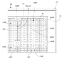
매립 플레이트(300)의 다양한 구성이 상기 핵연료 저장조(40)의 핵연료 랙(100)의 배치에 따라 제공될 수 있다. 각각의 내진 매립 플레이트(300)는 예를 들어 도5, 7 및 12에 도시된 바와 같이 적어도 하나의 매립 공동(302)을 포함한다. 전형적인 핵연료 저장조에 있어서, 상기 핵연료 랙(100)은 긴밀하게 이격되어 두 개 이상의 핵연료 랙의 적어도 모서리 영역이 예시적인 핵연료 저장조(40)의 평면도인 도3 에 도시된 바와 같이 서로 근접하여 위치한다. 인접한 핵연료 랙들 사이에 본 명세서에 기술된 수직 측 방향 측면(130) 및 상향 노출 베이스플레이트 돌출턱(220)는 각 핵연료 랙의 윤곽을 식별하는 두 개의 평행선으로서 표시되어(번호가 매겨져) 있다. 저장조의 둘레 또는 외주 핵연료 랙의 측면(130)은 측면(130)이 핵연료 저장조 측벽(41)에 인접하여 있는 단일 선으로 나타난다.Various configurations of the embedding
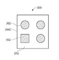
상기 핵연료 저장조(40)의 일부 위치에서, 두 개 이상의 핵연료 랙(100)으로부터 두 개 이상의 받침대(200)를 포획하기 위한 다수의 받침대-구속 공동(302)를 가지는 단일 대형 매립 플레이트(300)을 제공함으로써 경제성 및 설치 안정성을 달성할 수 있다. 다수의 공동을 가지는 이러한 매립 플레이트의 비 한정적 예들이 도8 및 도9에 도시되어 개념을 설명한다. 각 공동(302)은 동일한 매립 플레이트(300)상에서 다른 공동으로부터 공간적으로 분리되어 있어서 도시된 바와 같이 플레이트 상부벽(212)의 일부가 공동 사이에 있게 된다. 상기 공동(302)은 본 발명의 원리에 따라 인접한 핵연료 랙(100)들 및 그들의 받침대(200) 위치의 치수를 설명하기에 적절한 거리만큼 이격되어 있다.A single large buried
도3에 있어서, 매립 플레이트(300)들은 상기 매립 플레이트(300)들 및 그 공동(302)들과 결합하는 하나 이상의 받침대의 위치와 대체로 일치하는 'X'로 표시되어 있다. 예시적인 일 예로서, 6개의 인접한 핵연료 랙(100A, 100B, 100C, 100D, 100E, 100F)들은 설명을 위해 라벨화되어 있다. 단일-공동 매립 플레이트(300A)(예를 들어, 도7 또는 도12)는 예를 들어 랙(100A, 100C)의 단일 모서리 받침대(200)를 수용하도록 구성된 단일 매립 또는 구속 공동(302)을 갖는 상기 핵연료 저장조(40)의 각 측벽 (41) 모서리 영역(44)에 도시된다. 이중-공동 매립 플레이트(300B)(예를 들어, 도4 및 도8)는 두 개의 인접한 연료 랙(100A와100B, 100B와100C, 100C와100D, 및100A와100F)들 사이의 주변 경계 또는 교차점에 상기 핵연료 저장조의 측벽(41)을 따라 위치한다. 4중-공동 매립 플레이트(300C)(예를 들어, 도9)는 4개의 핵연료 랙의 모서리가 이를 테면 연료 랙(100A, 100B, 100E, 100F)과 랙(100B, 100C, 100D, 100E) 사이의 모서리 경계 또는 교차점에서 만나는 핵연료 저장조의 내부 영역에 위치한다. 각 다중-공동 매립 플레이트(300B 또는 300C)에 있는 공동들은 모두 동일한 형상이어야 할 필요는 없으며 각 공동에 수용되는 핵연료 랙 받침대(200)의 형상에 의존할 것임을 알 수 있다. 도9는 비 제한적 예로서 3개의 원형 공동(302) 및 하나의 직선형(예를 들어, 정사각형) 공동(302)를 가지는 매립 플레이트(300C)를 도시한다. 따라서, 매립 플레이트의 다양한 변형과 매립 공동들은 핵연료 랙의 설계 및 그 수용될 받침대 단면 형상에 따라 가능하다.In Figure 3, the buried
도3에 있어서, 각 핵연료 랙(100)의 내부 또는 내측 받침대(200A)의 예들이 도시된다. 이들 내부 받침대는 바람직하게는 받침대-구속 공동(302)을 포함할 수 있는 또는 대안적으로 상기 받침대(200A)를 삽입하기 위한 임의의 상부 리세스(recess)가 없는 완전히 평평한 종래의 매립 플레이트일 수 있는 짝을 이루는 매립 플레이트(300D)와 결합한다. 본 명세서의 다른 곳에서 설명된 바와 같이, 공동을 갖는 짝을 이루는 매립 플레이트(300)로 핵연료 랙의 외부 또는 외측 받침대를 제공하는 것은 지진 발생 시에 모든 수평 방향/측 방향으로 핵연료 랙의 이동을 억제하기에 충분하다. 도3에 도시된 핵연료 랙에서, 각각의 랙은 예를 들어 4개의 외부 모서리 받침대를 가진다(대형 핵연료 랙의 다른 가능한 실시의 예들은 모서리 받침대들 사이에 중간 외부 받침대를 가질 수 있다).In Fig. 3, examples of the inner or
상기 매립 플레이트(300)는 바람직하게는 제한 없이 스테인리스 강, 알루미늄 또는 다른 금속과 같은 적절한 강도의 적절한 부식 저항성 금속으로 형성된다. 선택된 금속은 설치를 용이하게 하는 이종(異種) 금속 용접을 요구하지 않고 상기 저장조 라이너(60)를 구성하는데 이용되는 금속의 유형에 용접하기에 적합하도록 선택적으로 선택될 수 있다.The buried
도4 내지 도6을 참조하여 내진 핵연료 저장조의 또 다른 특징에 따르면, 상기 핵연료 랙(100) 각각은 그 베이스플레이트(102)가 랙의 수직 측면(130)을 넘어서 거리(D6)만큼 수평 및 측 방향으로 외측으로 돌출하도록 구성되어, 돌출형 주변 턱(220)을 생성할 수 있다. 턱(220)은 상기 핵연료 랙(100)의 전체 둘레 주위를 완전히 둘러싸고 연장되어, 각 랙의 측면(예를 들어, 튜브 측벽(116))을 지진 발생시 손상으로부터 보호한다. 각각의 받침대는 미리 정해진 고정된 높이를 가질 수 있고 필요하다면 바닥에 끼워져, 모든 핵연료 랙 또는 모듈의 베이스플레이트(102)가 본질적으로 동일한 수평면(HP)(도5에서 참조됨) 내에 동일 평면 상에 있도록 한다. 지진 발생 중에, 실질적으로 동일한 수평면내에서의 베이스플레이트의 이러한 위치 설정(설치 공차를 인식하면서)과 베이스플레이트 주변 가장자리(208)로부터의 튜브 측벽(116)의 초과거리(set-back) 또는 오프셋 거리(D6)는 상기 셀(110)들을 손상으로부터 유리하게 보호하여 인접한 슬라이딩 핵연료 랙들 사이의 임의의 접촉은 랙의 주변 가장자리 사이에서만 발생하도록 보장한다. 이용되는 전형적인 오프셋 거리(D6)는 예를 들어 제한 없이1 내지 3인치일 수 있다. 보다 큰 또는 보다 작은 오프셋 거리가 다른 실시의 예에서 이용될 수 있다.4 to 6, each of the nuclear fuel racks 100 is configured such that the
대안적으로, 조절 가능한 받침대 구성은 끼움쇠(shim)의 필요를 회피하기 위하여 이용될 수 있다. 수직으로 높이를 조절하기 위한 2피스(piece) 나사산 다리 또는 받침대가 통상적으로 구비된 이러한 조절 가능한 받침대는 당 업계에 잘 알려져 있다. 도2A 및 도2B는 조절 가능한 받침대 설계의 예를 도시한다. 이러한 조절 가능한 높이 받침대 (200)는 베이스플레이트(102)의 바닥면에 연결된다. 일 실시의 예에서, 예를 들어 제한 없이, 조절 수단은 나사식 받침대 조립체를 통해 달성될 수 있다. 상기 조절 가능한 높이 받침대(200)는 핵연료 저장조(40)의 기저 슬라브(42)와 베이스플레이트(102)의 하부 표면 사이에 공간이 존재하는 것을 보장하여, 본 명세서의 다른 곳에서 설명된 바와 같이 물이 유동 홀(115) 및 셀(110)을 통해 상향으로 흐르는 유입구 플리넘(P)를 생성할 수 있다.Alternatively, an adjustable pedestal configuration can be used to avoid the need for a shim. These adjustable pedestals, which are typically equipped with two piece piece threaded legs or pedestals for adjusting the height vertically, are well known in the art. Figures 2A and 2B illustrate examples of adjustable pedestal designs. This
상기 조절 가능한 높이 받침대(200)는 이격되어 상기 베이스플레이트(102)와 그에 따른 상기 핵연료 랙(100)을 균일하게 지지한다. 이러한 각 받침대(200)는 바람직하게 개별적으로 조절 가능하여 불균일한 사용후 핵연료 기저 슬라브(42) 표면에서 상기 핵연료 랙을 수평을 이루고 지지함으로써, 모든 연료 랙(100)의 베이스플레이트(102)가 실질적으로 동일 평면 상에 있도록 보장하기 위한 끼움쇠 필요성을 피할 수 있다. 많은 가능한 구성의 일 예에서, 상기 받침대(200) 각각은 핵 연료 랙 베이스플레이트(102)의 바닥면에 견고하게 부착된 블록 형상의 직선형 상부 장착부(104)와, 상기 장착부에 나사 식으로 결합되고 상기 장착부에 대해 수직으로 이동 가능한 조절 가능 하부 기저부(105)를 포함할 수 있다. 상기 기저부(105)는 일 실시의 예에서 도시된 바와 같이 원형의 원통형일 수 있으며, 매립 플레이트 공동(302)의 바닥벽(306)과 결합하기 위한 안정된 베이스 패드(base pad)를 제공한다; 그러나, 다른 적절한 형상이 이용될 수 있다. 상기 받침대 장착부(104)는 일부 실시의 예에서 베이스플레이트(102)에 볼트 체결될 수 있다. 물론, 다른 실시의 예에서, 상기 장착부(104)는 단지 두 가지 예로서 용접 또는 나사 식 부착을 제한 없이 포함하는 다른 수단에 의해 베이스플레이트(102)에 부착될 수 있다.The
일부 실시의 예들에서, 지진 발생 동안 측 방향으로 미끄러지는 또는 이동하는 핵연료 랙들 사이의 손상의 가능성을 추가로 최소화하거나 방지하는 본 발명의 또 다른 특징에 따른 부가적인 수단이 제공될 수 있다. 인접한 연료 랙(100)들의 베이스플레이트(102)들(예를 들어, 수평 돌출턱(220)) 사이의 인접하고 마주하며 짝을 이루는 주변 가장자리(208)들이 지진 발생 이전의 정상 작동 조건에서 상기 핵연료 저장조에 설치시 상호 인접한 가장자리 접촉 또는 결합(abutting mutual edge contact or engagement)되도록 상기 핵연료 랙(100)은 상기 핵연료 저장조(40)의 기저 슬라브(42)에 배치될 수 있다. 짝을 이루는 베이스플레이트 주변 가장자리(208)들 사이에 형성된 인접 접합부(150)들을 가지는 이러한 가장자리 접촉 배열은 예로써 도3, 도4 및 도6에 도시된다. 도4는 그 사이에 베이스플레이트 인접 접합부(150)가 있는 제1 및 제2 핵연료 랙(100A, 100B)을 가장 잘 도시한다.In some embodiments, additional means in accordance with yet another aspect of the present invention may be provided that further minimizes or prevents the possibility of damage between the fuel racks sliding or moving laterally during the earthquake. The adjacent opposing
인접한 핵연료 랙(100)의 베이스플레이트(102)들 사이의 전술한 가장자리 접촉 배열은 인접한 핵연료 랙들 사이의 임의의 상당한 정도의 이동을 유리하게 방지한다. 이는 상기 베이스플레이트가 미리 결합되어 있기 때문에 지진 활동으로 인해 핵연료 랙의 측 방향 이동으로 야기되는 인접한 베이스플레이트들 사이의 초기 충격력을 제거한다. 지진 발생 전의 가장자리 접촉 배열로 인해, 이와 같이 결합된 상기 핵연료 랙(100)은 포획된 핵연료 랙 받침대(200)들이 매립 플레이트 공동 벽(204)과 결합하는 지점까지의 거리를 지진 활동 하에서 함께 측 방향으로 이동하거나 미끄러질 것이다. 유리하게는, 상기 핵연료 저장조(40) 내의 전체 랙 배열의 인접한 핵연료 랙에 대해 하나의 핵연료 랙(100)의 차동 운동이 없으므로 랙에 대한 상당한 손상이 제거될 수 있다.The aforementioned edge contact arrangement between the
금속 제조 공차로 인해, 완전한 등각 접촉이 비록 바람직하다 할지라도 두 개의 인접 베이스 플레이트(102) 사이에서 전체 수평 주변 가장자리 경계 길이를 따라 완전한 등각 접촉이 가능하지 않을 수 있다는 것을 알 수 있다. 예를 들어, 제한 없이 단지 1/4 인치인 최소 간극은 완전한 인접 등각 접촉이 금속 제조 한계로 인해 완전히 달성되지는 않을 수 있는 인접 핵연료 랙 베이스플레이트(102)들 사이에 만약 있다면 그 산재된 위치에서 합리적으로 얻을 수 있다. 그러나, 바람직하게는, 인접 등각 접촉은 핵연료 랙 베이스플레이트 주변 가장자리(208)의 상호 결합된 쌍들 사이에서 각 접합부(150)의 길이의 대부분에 대해 이루어진다(상기 등각 접촉이 작은 비-등각 접촉 영역에 의해 분리되는 짝을 이루는 베이스플레이트들을 따라 중간 길이에서 연속적으로 또는 불연속적으로 측정되는지 여부).It will be appreciated that due to metal manufacturing tolerances, complete conformal contact may not be possible along the entire horizontal perimeter edge boundary length between two
인접한 핵연료 랙 베이스 플레이트들 사이의 등각 접촉은 본 명세서에서 설명된 매립 플레이트 공동(302)의 대안으로서 일부 실시의 예에서 이용될 수 있거나, 또는 바람직하게는 지진 발생 중 핵연료 랙 손상에 대한 이중 보호를 제공하기 위해 공동과 함께 다른 실시의 예에서 이용될 수 있음을 유의해야 한다.Conformal contact between adjacent fuel rack base plates may be used in some embodiments as an alternative to the buried
핵연료 저장조에서의 핵연료의 내진 저장 프로세스 또는 방법은 여기서 설명된 내진 핵연료 저장 시스템에 기초하여 간략하게 설명한다. 일 실시의 예에서, 상기 방법은 랙을 저장조에 로딩하기 위한 핵 시설에서 상기 핵연료 저장조(40)에 근접한 복수개의 핵연료 랙(100)을 운반 및 결집(staging)하는 단계를 포함할 수 있다. 제1 핵연료 랙(100)은 크레인(미도시) 또는 적절한 리프팅(lifting) 장비를 통해 들어 올려지고 상기 핵연료 저장조(40) 위로 조종된다. 상기 제1 핵연료 랙(100)은 주변 받침대(200) 각각이 상기 저장조의 기저 슬라브(42) 상에서 대응하는 매립 플레이트(300)와 수직으로 정렬되도록 배향된다. 다음 단계는 상기 제1 핵연료 랙을 물이 채워진 핵연료 저장조로 낮추고 제1 핵연료 랙의 받침대 각각을 핵연료 저장조의 기저 슬라브에 고정식으로 이미 결합된 복수개의 매립 플레이트(300)에 형성된 대응하는 상향 개방된 매립 저장소 또는 공동(302)과 삽입가능하게 결합시키는 것이다. 상기 받침대(200)의 하단부는 공동의 움푹 패인 바닥벽(306)에 안착되고 측벽(304)은 그 안에 받침대를 잡아 준다. 지진 발생 동안 상기 받침대(200) 및 핵연료 랙의 상기 기저 슬라브(42)를 따르는 측 방향 이동은 받침대와 매립 플레이트의 매립 공동의 측벽 사이의 결합에 의해 제한된다.The seismic storage process or method of nuclear fuel in a nuclear fuel reservoir is briefly described based on the seismic resistant nuclear fuel storage system described herein. In one embodiment, the method may include transporting and staging a plurality of
상기 제1 핵연료 랙이 핵연료 저장조(40)에 위치된 후, 상기 방법은 제2 핵연료 랙(100)을 상기 핵연료 저장조로 낮추고, 상기 제2 핵연료 랙의 받침대(200) 각각을 핵연료 저장조의 기저 슬라브(42)에 고정식으로 결합된 상기 복수개의 매립 플레이트(300)에 형성된 대응하는 상향 개방된 저장소 또는 공동(302)과 삽입가능하게 결합시키고, 상기 제1 핵연료 랙의 베이스플레이트(102)의 주변 가장자리(208)를 상기 제2 핵연료 랙의 베이스플레이트의 인접한 주변 가장자리와 인접하게 결합시키는 것을 계속할 수 있다. 상기 제1 및 제2 핵연료 랙의 베이스플레이트(102)는 본 명세서에서 이미 기재된 바와 같이 실질적으로 동일 평면 상에 있어서 상호 결합을 보장한다. 어떤 상황에서는, 상기 제2 핵연료 랙(100)의 적어도 하나의 받침대(200) 및 제1 핵연료 랙의 적어도 하나의 받침대는 도8 및 도9에 각각 도시된 제한 없이 매립 플레이트(300B 또는 300C)와 같은 단일 공유 매립 플레이트에 형성된 개별 저장소와 결합할 수 있다. 전술한 방법에서 다양한 변형이 가능하다.After the first nuclear fuel rack is located in the
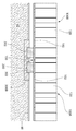
도14는 매립 플레이트(300)들이 그 사이에 개재(介在)된 저장조 라이너(60) 플레이트를 통해 핵연료 저장조(40)의 기저 슬라브(42)에 고정되는 매립 플레이트 시스템의 다른 실시의 예를 도시한다. 상기 매립 플레이트(300)의 바닥면은 상기 저장조 라이너(60)의 상면 상에 직접 안착된다. 상기 매립 플레이트 및 라이너(60)를 통해 기저 슬라브(42)로 수직으로 완전히 연장되는 하나 이상의 관통 금속 앵커(400)가 구비된다. 일 실시의 예에서, 상기 앵커(400)는, 하단부에서 상기 핵연료 저장조(40)의 기저 슬라브(42)로 나사식으로 고정되고 렌치(wrench)와 같은 조임 공구와 결합하기 위해 구성된 대향 단부에서 노출 확대된 헤드를 갖는 래그 볼트(lag bolt)와 같은 나사식 조임 체결구일 수 있다. 다른 유형의 앵커를 이용하는 것은 물론 가능하다. 이 실시의 예는 유사하게 상기 저장조 라이너(60)와 매립 플레이트(300) 사이의 임의의 상대적인 이동을 방지한다. 도5에 도시된 저장조 기저 슬라브(42)에 매립 플레이트(300)를 직접 매립하는 것은 만약 가능하다면 바람직하다 할지라도, 이 실시의 예는 본 발명에 따른 매립 플레이트 시스템이 라이너(60)를 가지는 기존의 핵연료 저장조(40)에 추가되는 개조 설치에 유용하다. 이는 매립 플레이트 위치에서 기존의 저장조 라이너(60)를 절삭할 필요를 제거한다. 상기 매립 플레이트(300)는 본 명세서에 이미 기재된 것과 유사한 방식으로 필릿 용접(fillet welds)(140)을 이용하여 그 둘레 주위로 라이너(60)에 완전하게 밀폐되게 용접될 수 있다.Figure 14 shows another embodiment of an embedding plate system in which the buried
도15는 매립 플레이트(300)들이 핵연료 저장조(40)의 기저 슬라브(42)에 고정되는 매립 플레이트 시스템의 제2 대안적인 실시의 예를 도시한다. 도14의 실시의 예와 대조적으로, 이 실시의 예에서, 상기 저장조 라이너(60) 플레이트의 어떠한 부분도 매립 플레이트(300)와 슬라브 사이에 개재되지 않는다. 상기 매립 플레이트(300)의 바닥면은 기저 슬라브(42)의 상면 상에 직접 안착된다. 상기 매립 플레이트를 통해 기저 슬라브(42)로 수직으로 완전히 연장되는 하나 이상의 관통 금속 앵커(400)가 구비된다. 이 실시의 예는 유사하게 상기 저장조 라이너(60)와 매립 플레이트(300) 사이의 임의의 상대적인 이동을 방지한다. 상기 매립 플레이트(300)는 본 명세서에 이미 기재된 것과 유사한 방식으로 필릿 용접(fillet welds)(140)을 이용하여 그 둘레 주위로 라이너(60)에 완전하게 밀폐되게 용접될 수 있다.15 shows a second alternative embodiment of a landfill plate system in which the buried
전술한 설명 및 도면은 본 발명의 바람직한 실시의 예들을 나타내지만, 다양한 추가, 변경 및 치환이 첨부된 특허청구범위의 균등물의 기술적 사상 및 범위의 이탈 없이 이루어질 수 있음을 이해해야 한다. 특히, 본 발명은 기술적 사상 또는 본질적인 특징을 벗어나지 않고, 다른 형태, 구조, 배치, 비율, 크기 및 다른 요소, 재질 및 구성 요소와 함께 실시될 수 있음은 당업자에게 명백할 것이다. 또한, 본 명세서에 설명되는 방법/프로세스에서 많은 변형이 본 발명의 범위 내에서 이루어질 수 있다. 당업자는 실시의 예들이 본 명세서에서 설명되는 원리에서 벗어남 없이 특정환경 및 동작가능 요구사항에 특히 적응되는 구조, 배치, 비율, 크기, 재질 및 구성요소의 많은 변경을 통해 사용될 수 있으며, 또한 본 발명의 실시에 사용될 수 있음을 더 이해할 것이다. 따라서, 현재 개시된 실시의 예들은 모든 측면에서 제한적이지 않으면서 예시적인 것이다. 첨부된 특허청구범위는 본 발명의 균등물의 범위에서 벗어나지 않고 당업자에 의해 이루어질 수 본 발명의 다른 변형과 실시의 예를 포함하도록 넓게 해석되어야 한다.It is to be understood that the foregoing description and drawings illustrate preferred embodiments of the invention, but it should be understood that various additions, alternations and substitutions can be made without departing from the spirit and scope of equivalents of the appended claims. In particular, it will be apparent to those skilled in the art that the present invention may be embodied in other forms, structures, arrangements, proportions, sizes, and other elements, materials, and components without departing from the spirit or essential characteristics thereof. In addition, many modifications in the methods / processes described herein may be made within the scope of the invention. Those skilled in the art will appreciate that the embodiments may be utilized without departing from the principles set forth herein and many modifications of the structure, arrangement, proportion, size, material, and components are specifically adapted to the specific environments and operable requirements, As will be understood by those skilled in the art. Accordingly, the presently disclosed embodiments are to be considered in all respects as illustrative and not restrictive. It is intended that the appended claims be construed to include other modifications and embodiments of the invention that may occur to those skilled in the art without departing from the scope of equivalents of the invention.
Claims (22)
공통 베이스플레이트(baseplate)에 부착되는 복수개의 수직으로 긴 튜브 모양의 셀을 포함하는 핵연료 랙(rack)으로서, 상기 셀 각각은 내부에 핵연료를 저장하도록 구성된 각기둥 형상의 공동을 정의하는, 핵연료 랙;
상기 베이스플레이트로부터 아래로 돌출하는 복수개의 받침대; 및
상기 기저 슬라브에 고정식으로 고정되는 복수개의 이격된 매립 플레이트로서, 각 매립 플레이트는 저장소의 깊이를 정의하는 저장소 벽을 가지는 상향으로 개방된 저장소를 포함하며, 각 저장소는 상기 핵연료 랙의 받침대들 중 하나를 수용하고 포획하는, 매립 플레이트;를 포함하고,
상기 매립 플레이트 저장소는, 지진 발생 시에 상기 핵연료 랙의 상기 기저 슬라브를 따른 측 방향 이동이 각 저장소의 상기 저장소 벽과 상기 받침대 사이의 결합에 의하여 제한되도록 구성되는,
내진(耐震) 핵연료 저장 시스템.A fuel reservoir comprising a plurality of vertical sidewalls collectively defining a base slab and a cavity configured for wet storage of the fuel;
A nuclear fuel rack comprising a plurality of vertically long tubular cells attached to a common base plate, each of said cells defining a prismatic cavity configured to store nuclear fuel therein;
A plurality of pedestals projecting downward from the base plate; And
A plurality of spaced buried plates fixedly secured to the base slab, each buried plate comprising an upwardly open reservoir having a reservoir wall defining a depth of reservoir, each reservoir including one of the bases of the nuclear fuel rack And a buried plate,
Wherein the buried plate reservoir is configured such that lateral movement of the fuel rack along the base slab upon occurrence of an earthquake is limited by engagement between the reservoir wall and the pedestal of each reservoir.
Earthquake resistant nuclear fuel storage system.
상기 받침대는 상기 핵연료 랙의 상기 베이스플레이트를 상기 기저 슬라브 위로 들어 올림으로써 바닥 플리넘(plenum)을 생성하여 저장조 물로 하여금 상기 핵연료의 냉각을 위해 상기 핵연료 랙의 아래로 순환하도록 하는,
핵연료 저장 시스템.The method according to claim 1,
Wherein the pedestal creates a bottom plenum by lifting the base plate of the fuel rack above the base slab to allow the stock to circulate down the fuel rack for cooling of the fuel,
Nuclear fuel storage system.
상기 셀은, 상기 베이스플레이트에 고정식으로 부착되고 상기 핵연료 랙의 측면을 집합적으로 정의하는 복수개의 상향 개방된 저장 튜브에 의하여 형성되는,
핵연료 저장 시스템.3. The method according to claim 1 or 2,
The cell being formed by a plurality of upwardly open storage tubes fixedly attached to the base plate and collectively defining sides of the nuclear fuel rack,
Nuclear fuel storage system.
상기 베이스플레이트는 상기 핵연료 랙의 상기 측면을 넘어서 수평 방향 외측으로 돌출되어, 상기 핵연료 랙의 둘레 주위로 연장되는 돌출형 주변 턱을 생성하는,
핵연료 저장 시스템.The method of claim 3,
The base plate projecting horizontally outward beyond the side of the fuel rack to create a protruding peripheral jaw extending around the periphery of the nuclear fuel rack,
Nuclear fuel storage system.
상기 저장소의 깊이는 1 내지 2인치의 깊이인,
핵연료 저장 시스템.The method according to claim 1,
The depth of the reservoir is a depth of 1 to 2 inches,
Nuclear fuel storage system.
상기 저장소는 상기 매립 플레이트의 중심 영역에 위치하고 상기 매립 플레이트의 평평한 상부벽으로 둘러싸이는,
핵연료 저장 시스템.The method according to any one of claims 1, 2, 4, or 5,
Said reservoir being located in a central region of said burying plate and surrounded by a flat top wall of said burying plate,
Nuclear fuel storage system.
상기 매립 플레이트는 제2 핵연료 랙으로부터 받침대를 수용하고 포획하기 위한 상기 저장소로부터 이격된 상향 개방된 제2 저장소를 포함하는,
핵연료 저장 시스템.The method according to claim 1,
Said buried plate comprising an upwardly open second reservoir spaced from said reservoir for receiving and capturing a pedestal from a second nuclear fuel rack,
Nuclear fuel storage system.
상기 받침대의 측벽과 상기 저장소 벽 사이에 형성된 수평 간극은 상기 받침대의 최대 가로지르는 단면 치수의 1/4보다 적은,
핵연료 저장 시스템.The method according to claim 1,
Wherein a horizontal clearance formed between the side wall of the pedestal and the reservoir wall is less than 1/4 of the maximum cross-sectional dimension of the pedestal,
Nuclear fuel storage system.
상기 핵연료 랙 아래의 상기 핵연료 저장조의 상기 기저 슬라브 상에 배치되고, 상기 복수개의 이격된 매립 플레이트들 사이로 연장되고 상기 매립 플레이트보다 적은 두께를 가지는 저장조 라이너(liner)를 더 포함하고, 지진 발생 시에 상기 매립 플레이트와 상기 저장조 라이너 사이에는 상대적인 이동이 없는,
핵연료 저장 시스템.The method according to claim 1,
Further comprising a reservoir liner disposed on the base slab of the fuel reservoir below the fuel rack and extending between the plurality of spaced buried plates and having a thickness less than the buried plate, Wherein there is no relative movement between the buried plate and the reservoir liner,
Nuclear fuel storage system.
상기 매립 플레이트 각각은 그 둘레 주위로 모든 측면에서 상기 저장조 라이너에 밀폐되게 용접되어 상기 핵연료 저장조로부터의 저장조 물의 외부 누출에 대한 불침투성 장벽을 형성하는,
핵연료 저장 시스템.10. The method of claim 9,
Each of said buried plates being hermetically welded to said reservoir liner at all sides about its perimeter to form an impermeable barrier to external leakage of the reservoir from said fuel reservoir,
Nuclear fuel storage system.
상기 매립 플레이트는 각 매립 플레이트 주위의 상기 저장조 라이너의 인접 부분들의 상면을 넘어서 상부로 돌출되는,
핵연료 저장 시스템.10. The method of claim 9,
Said buried plate projecting upwardly over an upper surface of adjacent portions of said reservoir liner around each buried plate,
Nuclear fuel storage system.
저장조 라이너가 상기 매립 플레이트와 상기 기저 슬라브 사이에 개재(介在)되지 않도록 상기 매립 플레이트는 상기 핵연료 저장조의 상기 기저 슬라브에 직접 매립되는,
핵연료 저장 시스템.The method according to claim 10 or 11,
Wherein the buried plate is directly buried in the base slab of the fuel reservoir so that the reservoir liner is not interposed between the buried plate and the base slab,
Nuclear fuel storage system.
상기 매립 플레이트는 각각은 상기 저장조 라이너의 상단 위에 배치되고, 각 매립 플레이트로부터 상기 저장조 라이너를 통해 상기 기저 슬라브로 연장되는 하나 이상의 관통 앵커(anchor) 에 의해, 상기 핵연료 저장조의 상기 기저 슬라브에 고정되는,
핵연료 저장 시스템.The method according to claim 10 or 11,
Each of the buried plates being disposed on top of the reservoir liner and secured to the base slab of the fuel reservoir by one or more through anchors extending from each buried plate through the reservoir liner to the base slab ,
Nuclear fuel storage system.
상기 기저 슬라브 상에 지지되는 복수개의 핵연료 랙으로서, 각 핵연료 랙은 공통 베이스플레이트(baseplate)에 부착되는 수직으로 긴 복수개의 튜브를 포함하고, 각 튜브는 핵연료를 안에 저장하도록 구성된 각기둥 형상의 공동(空洞)을 정의하며, 각 핵연료 랙은 상기 베이스플레이트로부터 아래로 돌출하는 이격된 복수개의 받침대를 포함하는, 핵연료 랙;
상기 기저 슬라브에 고정식으로 고정되는 복수개의 이격된 매립 플레이트로서, 각 매립 플레이트는 공동 벽을 가지는 상향으로 개방된 적어도 하나의 매립 공동을 가지며, 상기 공동 각각은 안에 상기 핵연료 랙들의 상기 받침대 중 하나를 수용하고 포획하는, 매립 플레이트; 및
상기 핵연료 저장조의 상기 기저 슬라브에 고정되고, 상기 복수개의 이격된 매립 플레이트 사이에서 연장되며 상기 매립 플레이트보다 작은 두께를 가지는 저장조 라이너(liner);를 포함하고,
상기 매립 플레이트의 둘레는 상기 매립 플레이트의 모든 측면 주위에서 상기 저장조 라이너에 밀폐되게 용접되어 상기 핵연료 저장조로부터의 저장조 물의 외부 누출에 대한 불침투성 장벽을 형성하고,
상기 매립 플레이트 공동은, 지진 발생에 의해 야기되는 상기 기저 슬라브를 따른 상기 핵연료 랙의 측 방향 이동이, 측 방향으로 작용하는 지진력이 상기 저장조 라이너로 전달되지 않도록, 각 공동의 상기 공동 벽과 상기 받침대 사이의 결합에 의하여 제한되도록 구성되는,
핵연료 내진(耐震) 저장을 위한 핵연료 랙(rack) 안정화 시스템.A fuel reservoir comprising a base slab and a plurality of vertical sidewalls collectively defining a cavity configured for underwater wet storage of the nuclear fuel;
A plurality of fuel racks supported on the base slab, each nuclear fuel rack comprising a plurality of vertically long tubes attached to a common base plate, each tube having a prismatic cavity Wherein each nuclear fuel rack comprises a plurality of spaced apart pedestals projecting downwardly from the base plate;
A plurality of spaced buried plates fixedly secured to said base slab, each buried plate having at least one buried cavity open upwardly having a cavity wall, each of said cavities having one of said supports of said nuclear fuel racks A buried plate to receive and capture; And
A reservoir liner secured to the base slab of the fuel reservoir and extending between the plurality of spaced buried plates and having a thickness less than the buried plate,
The perimeter of the buried plate is hermetically welded to the reservoir liner around all sides of the buried plate to form an impermeable barrier to external leakage of the reservoir from the fuel reservoir,
The buried plate cavity is configured such that the lateral movement of the nuclear fuel rack along the base slab caused by the occurrence of an earthquake is such that the seepage forces acting in the lateral direction are not transmitted to the reservoir liner, Lt; RTI ID = 0.0 > a < / RTI >
Nuclear Fuel Rack Stabilization System for Seismic Storage of Nuclear Fuel.
상기 핵연료 랙의 상기 베이스플레이트들은 실질적으로 서로 동일 평면 상에 배치되고 각 핵연료 랙의 상기 튜브의 상기 수직 측벽을 넘어서 측 방향으로 돌출되어 모든 측면에서 상기 핵연료 랙의 둘레 주위에서 수평 돌출턱을 형성하는,
핵연료 저장 시스템.15. The method of claim 14,
Wherein the base plates of the fuel rack are disposed substantially coplanar with each other and project laterally beyond the vertical sidewalls of the tubes of each nuclear fuel rack to form horizontal protruding tangs around the periphery of the fuel rack on all sides ,
Nuclear fuel storage system.
상기 핵연료 저장조에서 인접한 핵연료 랙들 사이의 짝을 이루는 수평 돌출턱들의 주변 가장자리들은 상호 인접하여 결합되어 있는,
핵연료 저장 시스템.16. The method according to claim 14 or 15,
Wherein the peripheral edges of the mating horizontal protrusions between adjacent fuel racks in the fuel reservoir are adjacent to each other,
Nuclear fuel storage system.
상기 짝을 이루는 수평 돌출턱들의 상기 주변 가장자리들은 상기 주변 가장자리의 길이의 대부분에 대해 상호 결합되는,
핵연료 저장 시스템.17. The method of claim 16,
Wherein the peripheral edges of the mating horizontal protrusions are mutually coupled with respect to a majority of the length of the peripheral edge,
Nuclear fuel storage system.
상기 핵연료 랙은 인접한 핵연료 랙들 사이의 짝을 이루는 베이스플레이트들이 상기 서로 짝을 이루는 베이스플레이트들의 주변 가장자리들 사이에서 수평으로 1/4인치 이하로 이격되도록 배열되는,
핵연료 저장 시스템.15. The method of claim 14,
Wherein the fuel racks are arranged such that mating base plates between adjacent fuel racks are spaced horizontally less than 1/4 inch between the peripheral edges of the mating base plates,
Nuclear fuel storage system.
상기 공동 벽은 원통형 또는 직선형 구성인,
핵연료 저장 시스템.15. The method of claim 14,
Wherein the cavity wall has a cylindrical or straight configuration,
Nuclear fuel storage system.
핵 시설에서 제1및 제2 핵연료 랙(rack)을 준비(staging)하는 단계로서, 핵연료 랙 각각은 내부에 핵연료를 저장하도록 구성된 각기둥 형상의 공동(空洞, cavity)을 각각 정의하는 복수개의 튜브를 포함하고, 상기 튜브는 공통 베이스플레이트상에 지지되며 상기 공통 베이스플레이트는 상기 베이스플레이트(baseplate)로부터 아래로 돌출하는 복수개의 받침대를 포함하는, 준비 단계;
기저 슬라브(base slab) 및 상기 기저 슬라브에 고정된 금속 저장조 라이너(liner)를 포함하는 물이 채워진 핵연료 저장조로 상기 제1 핵연료 랙을 낮추는 단계; 및
상기 제1 핵연료 랙의 상기 받침대 각각을 상기 핵연료 저장조의 상기 기저 슬라브에 고정식으로 고정된 복수개의 이격된 매립 플레이트에 형성된 대응하는 상향 개방된 저장소와 삽입가능하게 결합시키는 단계로서, 각 매립 플레이트는 상기 저장조에 밀폐되게 용접되어 상기 핵연료 저장조의 상기 기저 슬라브를 통한 저장조 물의 외부 누출에 대한 불침투성 장벽을 형성하는, 결합 단계;를 포함하고,
상기 매립 플레이트는, 지진 발생 동안 상기 기저 슬라브를 따른 상기 받침대의 측 방향 이동이, 측 방향으로 작용하는 지진력이 상기 저장조 라이너로 전달되지 않도록, 상기 받침대와 상기 매립 플레이트의 상기 저장소 사이의 결합에 의하여 제한되도록 구성되는,
핵연료 저장조에서의 핵연료의 내진 저장 방법.A method of seismic storage of nuclear fuel in a nuclear fuel reservoir,
Staging first and second nuclear fuel racks in a nuclear facility wherein each of the nuclear fuel racks comprises a plurality of tubes each defining a prismatic cavity configured to store nuclear fuel therein, Wherein the tube is supported on a common base plate and the common base plate comprises a plurality of pedestals projecting downwardly from the base plate;
Lowering the first fuel rack with a water-filled fuel reservoir comprising a base slab and a metal reservoir liner secured to the base slab; And
Inserting each of said pedestals of said first fuel rack into a corresponding upwardly open reservoir formed in a plurality of spaced buried plates fixedly secured to said base slab of said fuel reservoir, And a sealing step of sealingly welding to the reservoir to form an impermeable barrier to external leakage of the reservoir through the base slab of the fuel reservoir,
The buried plate is configured such that the lateral movement of the pedestal along the base slab during the occurrence of an earthquake is prevented by a coupling between the pedestal and the reservoir of the buried plate so that a laterally acting seismic force is not transmitted to the storage liner ≪ / RTI >
A Method for Seismic Storage of Nuclear Fuel in a Nuclear Fuel Storage Tank.
상기 물이 채워진 핵연료 저장조로 상기 제2 핵연료 랙을 낮추는 단계;
상기 제2 핵연료 랙의 상기 받침대 각각을 상기 핵연료 저장조의 상기 기저 슬라브에 고정식으로 결합된 상기 복수개의 이격된 매립 플레이트에 형성된 대응하는 상향 개방된 저장소와 삽입가능하게 결합시키는 단계; 및
상기 제1 핵연료 랙의 상기 베이스플레이트의 주변 가장자리를 상기 제2 핵연료 랙의 상기 베이스플레이트의 인접한 주변 가장자리와 인접하게 결합시키는 단계;를 더 포함하는,
핵연료 저장조에서의 핵연료의 내진 저장 방법.21. The method of claim 20,
Lowering the second fuel rack with the water filled fuel reservoir;
Inserting each of said pedestals of said second fuel rack into a corresponding upwardly open reservoir formed in said plurality of spaced buried plates fixedly coupled to said base slab of said fuel reservoir; And
Further comprising: coupling a peripheral edge of the base plate of the first fuel rack adjacent the adjacent peripheral edge of the base plate of the second fuel rack,
A Method for Seismic Storage of Nuclear Fuel in a Nuclear Fuel Storage Tank.
상기 제2 핵연료 랙의 적어도 하나의 받침대와 상기 제1 핵연료 랙의 적어도 하나의 받침대는 단일 공유 매립 플레이트에 형성된 개별 저장소와 결합되는,
핵연료 저장조에서의 핵연료의 내진 저장 방법.22. The method according to claim 20 or 21,
Wherein at least one pedestal of said second fuel rack and at least one pedestal of said first nuclear fuel rack are combined with an individual reservoir formed in a single shared buried plate,
A Method for Seismic Storage of Nuclear Fuel in a Nuclear Fuel Storage Tank.
Applications Claiming Priority (4)
| Application Number | Priority Date | Filing Date | Title |
|---|---|---|---|
| US201762463319P | 2017-02-24 | 2017-02-24 | |
| US62/463,319 | 2017-02-24 | ||
| US15/618,774 | 2017-06-09 | ||
| US15/618,774 US10847274B2 (en) | 2017-02-24 | 2017-06-09 | Earthquake-resistant fuel storage rack system for fuel pools in nuclear plants |
Publications (2)
| Publication Number | Publication Date |
|---|---|
| KR20180098162A true KR20180098162A (en) | 2018-09-03 |
| KR102103451B1 KR102103451B1 (en) | 2020-04-22 |
Family
ID=61274093
Family Applications (1)
| Application Number | Title | Priority Date | Filing Date |
|---|---|---|---|
| KR1020180021655A Expired - Fee Related KR102103451B1 (en) | 2017-02-24 | 2018-02-23 | High earthquake-resistant fuel storage rack system for fuel pools in nuclear plants |
Country Status (4)
| Country | Link |
|---|---|
| US (1) | US10847274B2 (en) |
| EP (1) | EP3367389B1 (en) |
| KR (1) | KR102103451B1 (en) |
| CN (1) | CN108511098B (en) |
Families Citing this family (11)
| Publication number | Priority date | Publication date | Assignee | Title |
|---|---|---|---|---|
| US11289227B2 (en) * | 2018-11-29 | 2022-03-29 | Holtec International | Spent nuclear fuel canister |
| TWI795484B (en) * | 2017-12-20 | 2023-03-11 | 美商Tn美國有限責任公司 | Modular basket assembly for fuel assemblies |
| CN109243645B (en) * | 2018-09-13 | 2022-03-01 | 中国核动力研究设计院 | Spent fuel assembly storage grillwork |
| JP7195969B2 (en) * | 2019-02-20 | 2022-12-26 | 三菱重工業株式会社 | NUCLEAR FUEL STORAGE RACK, METHOD FOR INSTALLING NUCLEAR FUEL STORAGE RACK, AND METHOD FOR MANUFACTURING NUCLEAR FUEL STORAGE RACK |
| EP3953948B1 (en) | 2019-04-12 | 2023-08-23 | Materion Corporation | Cask liner for nuclear fuel cask |
| JP6698924B1 (en) * | 2019-08-02 | 2020-05-27 | 三菱重工業株式会社 | Frame design method and frame |
| CN114846563A (en) * | 2019-12-09 | 2022-08-02 | 霍尔泰克国际公司 | Nuclear fuel storage system with integral gasket |
| EP4128283A4 (en) | 2020-04-01 | 2024-05-01 | Holtec International | STORAGE SYSTEM FOR RADIOACTIVE NUCLEAR WASTE WITH PRESSURE SURGE PROTECTION |
| US12112856B2 (en) * | 2021-10-26 | 2024-10-08 | Holtec International | Spent nuclear fuel storage rack system |
| CN114754600B (en) * | 2022-03-21 | 2022-12-09 | 三江化工有限公司 | Steam condensate water heat recycling system in storage and transportation system |
| CN114620384B (en) * | 2022-04-11 | 2023-05-30 | 江苏西顿科技有限公司 | Storage shelf for nuclear waste |
Citations (3)
| Publication number | Priority date | Publication date | Assignee | Title |
|---|---|---|---|---|
| JP2010160154A (en) * | 2009-01-09 | 2010-07-22 | Cci Ag | Storage rack structure for storing nuclear fuel element |
| KR20140103333A (en) * | 2011-12-22 | 2014-08-26 | 홀텍 인터내셔날, 인크. | Storage system for nuclear fuel |
| JP2015152443A (en) * | 2014-02-14 | 2015-08-24 | 三菱重工業株式会社 | storage rack |
Family Cites Families (12)
| Publication number | Priority date | Publication date | Assignee | Title |
|---|---|---|---|---|
| KR810001479B1 (en) * | 1978-03-18 | 1981-10-23 | 챨스 알. 라인 | Nuclear fuel rack lateral restraint |
| US4820472A (en) * | 1981-07-14 | 1989-04-11 | Westinghouse Electric Corp. | Nuclear reactor spent fuel storage rack |
| US4436693A (en) * | 1981-09-18 | 1984-03-13 | Automation Industries, Inc. | Non-impacting loose rod storage canister |
| US4889681A (en) * | 1981-10-19 | 1989-12-26 | U.S. Tool & Die, Inc. | Apparatus for reducing floor and seismic loadings in underwater storage areas used in the storing of spent nuclear fuel rods |
| US5245641A (en) | 1981-12-22 | 1993-09-14 | Westinghouse Electric Corp. | Spent fuel storage rack |
| DE3430180A1 (en) | 1984-08-16 | 1986-02-27 | Kraftwerk Union AG, 4330 Mülheim | Liner for a compartment in a nuclear installation |
| JPH10186074A (en) * | 1996-12-27 | 1998-07-14 | Mitsubishi Heavy Ind Ltd | Aseismatic grid of fuel assembly for nuclear reactor, fuel assembly, and nuclear reactor core |
| WO2008079439A2 (en) * | 2006-07-10 | 2008-07-03 | Holtec International, Inc. | Apparatus, system and method for facilitating transfer of high level radioactive waste to and/or from a pool |
| JP5610960B2 (en) | 2010-09-29 | 2014-10-22 | 三菱重工業株式会社 | Nuclear fuel storage rack |
| KR101857677B1 (en) | 2011-07-21 | 2018-05-14 | 에스케이하이닉스 주식회사 | Semiconductor integrated circuit and method of transmitting signal thereof |
| WO2014036158A2 (en) | 2012-08-28 | 2014-03-06 | Holtec International, Inc. | System and method for minimizing movement of nuclear fuel racks during a seismic event |
| EP3204949B1 (en) * | 2014-10-07 | 2019-09-04 | Holtec International | Environmentally sequestered spent fuel pool |
-
2017
- 2017-06-09 US US15/618,774 patent/US10847274B2/en active Active
-
2018
- 2018-02-22 EP EP18158156.2A patent/EP3367389B1/en active Active
- 2018-02-23 KR KR1020180021655A patent/KR102103451B1/en not_active Expired - Fee Related
- 2018-02-23 CN CN201810155193.6A patent/CN108511098B/en not_active Expired - Fee Related
Patent Citations (3)
| Publication number | Priority date | Publication date | Assignee | Title |
|---|---|---|---|---|
| JP2010160154A (en) * | 2009-01-09 | 2010-07-22 | Cci Ag | Storage rack structure for storing nuclear fuel element |
| KR20140103333A (en) * | 2011-12-22 | 2014-08-26 | 홀텍 인터내셔날, 인크. | Storage system for nuclear fuel |
| JP2015152443A (en) * | 2014-02-14 | 2015-08-24 | 三菱重工業株式会社 | storage rack |
Also Published As
| Publication number | Publication date |
|---|---|
| KR102103451B1 (en) | 2020-04-22 |
| EP3367389A1 (en) | 2018-08-29 |
| CN108511098B (en) | 2022-03-25 |
| EP3367389B1 (en) | 2019-12-18 |
| US10847274B2 (en) | 2020-11-24 |
| CN108511098A (en) | 2018-09-07 |
| US20180247720A1 (en) | 2018-08-30 |
Similar Documents
| Publication | Publication Date | Title |
|---|---|---|
| KR102103451B1 (en) | High earthquake-resistant fuel storage rack system for fuel pools in nuclear plants | |
| KR102565253B1 (en) | Reactor module support structure | |
| US11610696B2 (en) | Nuclear waste cask with impact protection, impact amelioration system for nuclear fuel storage, unventilated cask for storing nuclear waste, and storage and transport cask for nuclear waste | |
| US8660231B2 (en) | Storage rack arrangement for the storage of nuclear fuel elements | |
| JP2014529079A (en) | Ventilation system for storing high-level radioactive waste | |
| KR20130038867A (en) | Nuclear reactor containment vessel | |
| US20180301231A1 (en) | Apparatus for supporting spent nuclear fuel | |
| EP4100970A1 (en) | Unventilated cask for storing nuclear waste | |
| US20230268095A1 (en) | Impact amelioration system for nuclear fuel storage | |
| US12340911B2 (en) | Fuel rack apparatus having storage tubes comprising interior flux trap chambers | |
| US12033764B2 (en) | Fuel rack for storing spent nuclear fuel | |
| JP7178280B2 (en) | Restraint device, rack for nuclear fuel storage, and method for restraining rack for nuclear fuel storage | |
| US12567509B2 (en) | Spent nuclear fuel storage rack system with reactivity controls | |
| US12112856B2 (en) | Spent nuclear fuel storage rack system | |
| WO2024206705A1 (en) | Fuel storage rack system for underwater storage of spent nuclear fuel | |
| Liszkai et al. | Reactor module support structure | |
| HK1249960B (en) | Reactor module support structure |
Legal Events
| Date | Code | Title | Description |
|---|---|---|---|
| E13-X000 | Pre-grant limitation requested |
St.27 status event code: A-2-3-E10-E13-lim-X000 |
|
| PA0109 | Patent application |
St.27 status event code: A-0-1-A10-A12-nap-PA0109 |
|
| A201 | Request for examination | ||
| PA0201 | Request for examination |
St.27 status event code: A-1-2-D10-D11-exm-PA0201 |
|
| P11-X000 | Amendment of application requested |
St.27 status event code: A-2-2-P10-P11-nap-X000 |
|
| P13-X000 | Application amended |
St.27 status event code: A-2-2-P10-P13-nap-X000 |
|
| PG1501 | Laying open of application |
St.27 status event code: A-1-1-Q10-Q12-nap-PG1501 |
|
| D13-X000 | Search requested |
St.27 status event code: A-1-2-D10-D13-srh-X000 |
|
| D14-X000 | Search report completed |
St.27 status event code: A-1-2-D10-D14-srh-X000 |
|
| E902 | Notification of reason for refusal | ||
| PE0902 | Notice of grounds for rejection |
St.27 status event code: A-1-2-D10-D21-exm-PE0902 |
|
| E13-X000 | Pre-grant limitation requested |
St.27 status event code: A-2-3-E10-E13-lim-X000 |
|
| P11-X000 | Amendment of application requested |
St.27 status event code: A-2-2-P10-P11-nap-X000 |
|
| P13-X000 | Application amended |
St.27 status event code: A-2-2-P10-P13-nap-X000 |
|
| E701 | Decision to grant or registration of patent right | ||
| PE0701 | Decision of registration |
St.27 status event code: A-1-2-D10-D22-exm-PE0701 |
|
| GRNT | Written decision to grant | ||
| PR0701 | Registration of establishment |
St.27 status event code: A-2-4-F10-F11-exm-PR0701 |
|
| PR1002 | Payment of registration fee |
St.27 status event code: A-2-2-U10-U11-oth-PR1002 Fee payment year number: 1 |
|
| PG1601 | Publication of registration |
St.27 status event code: A-4-4-Q10-Q13-nap-PG1601 |
|
| PR1001 | Payment of annual fee |
St.27 status event code: A-4-4-U10-U11-oth-PR1001 Fee payment year number: 4 |
|
| PR1001 | Payment of annual fee |
St.27 status event code: A-4-4-U10-U11-oth-PR1001 Fee payment year number: 5 |
|
| PC1903 | Unpaid annual fee |
St.27 status event code: A-4-4-U10-U13-oth-PC1903 Not in force date: 20250417 Payment event data comment text: Termination Category : DEFAULT_OF_REGISTRATION_FEE |
|
| H13 | Ip right lapsed |
Free format text: ST27 STATUS EVENT CODE: N-4-6-H10-H13-OTH-PC1903 (AS PROVIDED BY THE NATIONAL OFFICE); TERMINATION CATEGORY : DEFAULT_OF_REGISTRATION_FEE Effective date: 20250417 |
|
| PC1903 | Unpaid annual fee |
St.27 status event code: N-4-6-H10-H13-oth-PC1903 Ip right cessation event data comment text: Termination Category : DEFAULT_OF_REGISTRATION_FEE Not in force date: 20250417 |