KR20180098115A - Earthquake-proof deck insert - Google Patents
Earthquake-proof deck insert Download PDFInfo
- Publication number
- KR20180098115A KR20180098115A KR1020170154538A KR20170154538A KR20180098115A KR 20180098115 A KR20180098115 A KR 20180098115A KR 1020170154538 A KR1020170154538 A KR 1020170154538A KR 20170154538 A KR20170154538 A KR 20170154538A KR 20180098115 A KR20180098115 A KR 20180098115A
- Authority
- KR
- South Korea
- Prior art keywords
- hole
- support
- bolt
- deck plate
- deck
- Prior art date
- Legal status (The legal status is an assumption and is not a legal conclusion. Google has not performed a legal analysis and makes no representation as to the accuracy of the status listed.)
- Granted
Links
Images




Classifications
-
- E—FIXED CONSTRUCTIONS
- E04—BUILDING
- E04B—GENERAL BUILDING CONSTRUCTIONS; WALLS, e.g. PARTITIONS; ROOFS; FLOORS; CEILINGS; INSULATION OR OTHER PROTECTION OF BUILDINGS
- E04B1/00—Constructions in general; Structures which are not restricted either to walls, e.g. partitions, or floors or ceilings or roofs
- E04B1/38—Connections for building structures in general
- E04B1/41—Connecting devices specially adapted for embedding in concrete or masonry
-
- E—FIXED CONSTRUCTIONS
- E04—BUILDING
- E04B—GENERAL BUILDING CONSTRUCTIONS; WALLS, e.g. PARTITIONS; ROOFS; FLOORS; CEILINGS; INSULATION OR OTHER PROTECTION OF BUILDINGS
- E04B5/00—Floors; Floor construction with regard to insulation; Connections specially adapted therefor
- E04B5/16—Load-carrying floor structures wholly or partly cast or similarly formed in situ
- E04B5/32—Floor structures wholly cast in situ with or without form units or reinforcements
- E04B5/36—Floor structures wholly cast in situ with or without form units or reinforcements with form units as part of the floor
- E04B5/38—Floor structures wholly cast in situ with or without form units or reinforcements with form units as part of the floor with slab-shaped form units acting simultaneously as reinforcement; Form slabs with reinforcements extending laterally outside the element
Landscapes
- Engineering & Computer Science (AREA)
- Architecture (AREA)
- Physics & Mathematics (AREA)
- Electromagnetism (AREA)
- Civil Engineering (AREA)
- Structural Engineering (AREA)
- Joining Of Building Structures In Genera (AREA)
Abstract
본 발명은 데크 인서트에 관한 것으로서, 건물의 슬라브용 데크플레이트의 소정 관통공을 통해 앙카볼트를 설치하기 위한 데크 인서트에 있어서, 상기 데크플레이트의 상면에 배치되고 일측에 상기 관통공과 연통되는 제1관통공이 형성되며 상면에 타설되는 콘크리트의 가압력이나 지진 등에 의해 파쇄된 콘크리트의 가압력에 저항하는 가압저항부가 마련된 상면지지대(10); 상기 제1관통공을 관통하여 상측부가 상기 상면지지대의 상방에 위치되고 하측부가 상기 관통공 하방으로 돌출되며 하단부 일측에 제1연결부가 마련된 가압핀(20); 상기 가압핀의 제1연결부와 연결되는 제2연결부가 상측에 마련되고 하측에 앙카볼트와 연결되는 볼트연결부가 마련된 볼트연결구(30); 상기 가압핀과 볼트연결구 사이에 고정되고 일측에 데크플레이트의 저면을 떠받치는 떠받침부가 마련된 저면지지대(40); 및 상기 상면지지대와 가압핀 사이에 개재되어 상기 상면지지대와 저면지지대에 각각 탄발력을 제공하는 탄성체(50);를 포함한다. 따라서, 기본적으로 외력에 저항하여 앙카볼트가 기울어지는 등의 우려없이 견고하고 안정적으로 데크플레이트에 설치할 수 있게 되면서 안정성 향상을 도모할 수 있도록 하고, 또한, 상면지지대와 저면지지대를 절연재질로 제작하여 앙카볼트를 통한 전기가 상기 데크플레이트로 전달되는 것을 차단함으로써 안전사고 발생을 미연에 예방할 수 있는 등의 효과를 얻는다. A deck insert for installing an anchor bolt through a predetermined through hole of a deck plate for a slab of a building, the deck insert comprising: a first through hole disposed on an upper surface of the deck plate and communicating with the through hole on one side, An upper surface support member 10 having a pressure resistance portion for forming a hole and resisting the pressing force of concrete crushed by an earthquake or the like; A push pin (20) passing through the first through hole, an upper portion positioned above the upper surface support, a lower portion projecting downwardly from the through hole, and a first connection portion provided at a lower end; A bolt connection port 30 provided on the upper side with a second connection portion connected to the first connection portion of the pressing pin and having a bolt connection portion connected to the anchor bolt on the lower side; A bottom support base 40 fixed between the pressing pin and the bolt connection hole and having a support portion for supporting the bottom surface of the deck plate at one side; And an elastic body (50) interposed between the upper surface support and the pressing pin to provide elastic force to the upper surface support and the lower surface support, respectively. Therefore, it is possible to mount on the deck plate firmly and stably without fear of tilting of the anchor bolt against the external force, and to improve the stability. In addition, the upper surface support table and the lower surface support table are made of an insulating material It is possible to prevent the occurrence of a safety accident by preventing electricity from being transmitted to the deck plate through the anchor bolt.
Description
본 발명은 데크 인서트에 관한 것으로서, 보다 상세하게는 상기 데크플레이트의 상면에 배치되고 제1관통공과 가압저항부가 마련된 상면지지대와, 상기 제1관통공을 관통하고 제1연결부가 마련된 가압핀과, 상기 제1연결부와 연결되는 제2연결부와 앙카볼트와 연결되는 볼트연결부가 마련된 볼트연결구와, 데크플레이트의 저면을 떠받치는 떠받침부가 마련된 저면지지대와, 상기 상면지지대와 가압핀 사이에 개재되는 탄성체를 포함하는 내진 데크 인서트에 관한 것이다.The present invention relates to a deck insert, and more particularly, to a deck insert having a top support base disposed on an upper surface of the deck plate and having a first through hole and a pressure resistance portion, a press pin having a first connection portion through the first through hole, A bolt connecting port having a second connecting portion connected to the first connecting portion and a bolt connecting portion connected to the anchor bolt, a bottom supporting base having a supporting portion for supporting the bottom surface of the deck plate, and an elastic member interposed between the top supporting rod and the pressing pin, The present invention relates to an earthquake-resistant deck insert.
일반적으로 빌딩이나 고층건물 등은 금속재로 된 I빔 형강을 상호 연결하여 건물의 프레임을 만든 후에 다시 I빔 형강에 거푸집 역할을 하는 데크프레이트를 설치하여 철근 등을 체결한 다음에 콘크리트를 타설하여 건축하는 방식으로써, 이렇게 건축되는 빌딩이나 고층건물 등에는 각종 전기기구나 환풍용 덕트 등 여러가지의 시설물들을 설치하기 위해 콘크리트를 타설하기 전에 데크프레이트에 시설물 고정수단인 앙카볼트를 설치한다. Generally, a building or a high-rise building is constructed by connecting I beam steel beams made of metal to construct a frame of a building, and then installing a deck plate to serve as a formwork in the I beam steel, In order to install various kinds of facilities such as various electric appliances and ventilation ducts in a building or a high-rise building to be constructed in this way, an anchor bolt, which is a facility fixing means, is installed on the deck plate before the concrete is installed.
이러한 앙카볼트는 다층건물의 건축시 각층의 제반시설, 즉 수도, 전기, 덕트나 천정구조물의 견고한 설치가 요망되기 때문에 견고한 고정구조가 필요하다. Such anchor bolts require a rigid fixing structure because it is required to rigidly install various facilities such as water, electricity, ducts and ceiling structures in the construction of multi-story buildings.
그러나, 이러한 종래 기술의 앙카볼트는 흔들림을 방지하기 위한 흔들림방지수단이 마련되어 있지 않기 때문에, 콘크리트 타설시나 지진 등에 의해 파쇄된 콘크리트의 가압력에 의해 앙카볼트의 축이 밀려 기울어지게 되면서 결과적으로 시설물이 파손되거나 설치 상태가 불량하게 되는 등의 문제점을 갖고 있었다.However, since such an anchor bolt of the prior art does not have a shake preventing means for preventing shaking, the axis of the anchor bolt is tilted by the pressing force of the crushed concrete due to the concrete pouring or earthquake, Or the installation state is poor.
그리고, 앙카볼트를 포함한 주변 구성부품들이 대부분 비철금속 등 비절연체로 되어 있기 때문에, 앙카볼트를 통한 전기가 상기 데크플레이트로 전달되어 안전사고로 이어질 우려가 있음은 물론 비철금속 자체가 고가여서 이에 따른 비용부담 등의 문제점도 갖고 있었다.Since most peripheral components including anchor bolts are made of non-insulated materials such as non-ferrous metals, electricity through the anchor bolts may be transmitted to the deck plate, leading to safety accidents, as well as the high cost of non-ferrous metals themselves And the like.
본 발명은 이러한 문제점을 해결하기 위해서 안출된 것으로서, 상기 데크플레이트의 상면에 배치되고 제1관통공과 가압저항부가 마련된 상면지지대와, 상기 제1관통공을 관통하고 제1연결부가 마련된 가압핀과, 상기 제1연결부와 연결되는 제2연결부와 앙카볼트와 연결되는 볼트연결부가 마련된 볼트연결구와, 데크플레이트의 저면을 떠받치는 떠받침부가 마련된 저면지지대와, 상기 상면지지대와 가압핀 사이에 개재되는 탄성체를 마련함으로써, 기본적으로 외력에 저항하여 앙카볼트가 기울어지는 등의 우려없이 견고하고 안정적으로 데크플레이트에 설치할 수 있도록 하는 데크 인서트를 제공하는데 그 목적이 있다. SUMMARY OF THE INVENTION The present invention has been conceived in order to solve the above problems, and it is an object of the present invention to provide a deck plate which has an upper surface support member disposed on an upper surface of the deck plate and having a first through hole and a pressure resistance portion, A bolt connecting port having a second connecting portion connected to the first connecting portion and a bolt connecting portion connected to the anchor bolt, a bottom supporting base having a supporting portion for supporting the bottom surface of the deck plate, and an elastic member interposed between the top supporting rod and the pressing pin, It is an object of the present invention to provide a deck insert which can be firmly and stably mounted on a deck plate without fear of tilting an anchor bolt against an external force.
또한, 상면지지대와 저면지지대를 절연재질(플라스틱)로 제작하여 앙카볼트를 통한 전기가 상기 데크플레이트로 전달되는 것을 차단할 수 있도록 하는 데크 인서트를 제공하는데 다른 목적이 있다. It is another object of the present invention to provide a deck insert which is made of an insulating material (plastic) so that the top surface support and the bottom surface support can be prevented from being transmitted to the deck plate through the anchor bolt.
이와 같은 상기 목적을 달성하기 위한 본 발명의 일 실시예에 따른 내진 데크 인서트는 건물의 슬라브용 데크플레이트의 소정 관통공을 통해 앙카볼트를 설치하기 위한 데크 인서트에 있어서, 상기 데크플레이트의 상면에 배치되고 일측에 상기 관통공과 연통되는 제1관통공이 형성되며 상면에 타설되는 콘크리트의 가압력이나 지진 등에 의해 파쇄된 콘크리트의 가압력에 저항하는 가압저항부가 마련된 상면지지대; 상기 제1관통공을 관통하여 상측부가 상기 상면지지대의 상방에 위치되고 하측부가 상기 관통공 하방으로 돌출되며 하단부 일측에 제1연결부가 마련된 가압핀; 상기 가압핀의 제1연결부와 연결되는 제2연결부가 상측에 마련되고 하측에 앙카볼트와 연결되는 볼트연결부가 마련된 볼트연결구; 상기 가압핀과 볼트연결구 사이에 고정되고 일측에 데크플레이트의 저면을 떠받치는 떠받침부가 마련된 저면지지대; 및 상기 상면지지대와 가압핀 사이에 개재되어 상기 상면지지대와 저면지지대에 각각 탄발력을 제공하는 탄성체;를 포함한다.According to another aspect of the present invention, there is provided an anti-earthquake deck insert for mounting an anchor bolt through a predetermined through-hole of a slab deck plate of a building, the deck insert comprising: An upper surface support having a first through hole communicating with the through hole at one side thereof and provided with a pressure resistance portion for resisting the pressing force of the concrete crushed by the pressing force or the earthquake of the concrete placed on the upper surface; A pressing pin passing through the first through hole and having an upper portion located above the upper surface support, a lower portion protruding downwardly from the through hole, and a first connecting portion provided at a lower end of the lower portion; A bolt connecting portion provided on the upper side with a second connecting portion connected to the first connecting portion of the pressing pin and having a bolt connecting portion connected to the anchor bolt on the lower side; A lower surface support member fixed between the pressing pin and the bolt connecting member and having a support portion for supporting a bottom surface of the deck plate at one side; And an elastic body interposed between the upper surface support and the pressing pin to provide an elastic force to the upper surface support and the lower surface support, respectively.
또한, 본 발명의 일 실시예에 따른 내진 데크 인서트에 있어서, 상기 상면지지대는, 상기 데크플레이트의 상면에 밀착되고 중앙에 상기 제1관통공이 형성되며 상기 제1관통공 테두리를 따라 상기 가압저항부가 복수개 마련된 지지판; 및 상기 제1관통공의 테두리에서 상기 관통공을 따라 하방으로 연장되는 지지관체;를 포함하는 것일 수 있다.Further, in the earthquake-resistant deck insert according to an embodiment of the present invention, the upper surface support bar is closely attached to the upper surface of the deck plate, the first through hole is formed at the center, A plurality of support plates; And a support tube extending downward along the through-hole at an edge of the first through-hole.
또한, 본 발명의 일 실시예에 따른 내진 데크 인서트에 있어서, 상기 가압저항부는 상기 제1관통공의 테두리에서 일정높이 상향 직립되고 상기 지지판의 테두리에서는 상기 상향 직립되는 방향으로 상향 경사진 경사판 구조로 된 것일 수 있다.Further, in the earthquake-resistant deck insert according to an embodiment of the present invention, the pressing resistance portion may have a slanting plate structure that is erected upward at a predetermined height from the rim of the first through-hole and inclined upward in the upright- .
또한, 본 발명의 일 실시예에 따른 내진 데크 인서트에 있어서, 상기 복수의 가압저항부는 상기 제1관통공의 테두리를 따라 등간격으로 이격되는 구조로 된 것일 수 있다.Further, in the earthquake-resistant deck insert according to an embodiment of the present invention, the plurality of pressing resistance portions may be structured so as to be spaced apart at regular intervals along the rim of the first through hole.
또한, 본 발명의 일 실시예에 따른 내진 데크 인서트에 있어서, 상기 가압저항부는 상단면에 상기 탄성체의 하단부가 안착되도록 하방으로 오목하게 패인 안착홈이 마련된 것일 수 있다.Further, in the earthquake-proof deck insert according to an embodiment of the present invention, the pressing resistance portion may have a seating groove recessed downward so that the lower end of the elastic body is seated on the upper surface.
또한, 본 발명의 일 실시예에 따른 내진 데크 인서트에 있어서, 상기 가압핀은 외주면에 상기 탄성체가 감싸는 형상으로 배치되고 상단부에 상기 탄성체의 상단부가 걸려 지지되도록 하는 대직경 판재 형상의 버튼부가 마련된 것일 수 있다.Further, in the earthquake-resistant deck insert according to an embodiment of the present invention, the pressing pin is disposed in the shape of wrapping the elastic body on the outer circumferential surface, and the upper end portion of the pushing pin is provided with a button portion of a large- .
또한, 본 발명의 일 실시예에 따른 내진 데크 인서트에 있어서, 상기 버튼부는 콘크리트와 맞물려 상기 가압핀의 축회전이 방지되도록 저면 테두리를 따라 복수의 회전방지돌기가 마련된 것일 수 있다.Further, in the earthquake-resistant deck insert according to an embodiment of the present invention, the button portion may be provided with a plurality of anti-rotation protrusions along the bottom surface of the bottom portion so as to prevent rotation of the pressing pin.
또한, 본 발명의 일 실시예에 따른 내진 데크 인서트에 있어서, 상기 가압핀의 제1연결부와 상기 볼트연결구의 제2연결부는 각각 서로가 나사 결합되도록 하는 나사산 구조로 된 것일 수 있다.Further, in the earthquake-resistant deck insert according to an embodiment of the present invention, the first connecting portion of the pressing pin and the second connecting portion of the bolt connecting portion may have a threaded structure for screwing each other.
또한, 본 발명의 일 실시예에 따른 내진 데크 인서트에 있어서, 상기 가압핀은 상기 상단부의 버튼부와 하단부의 제1연결부 사이에 원기둥 형상의 본체가 마련되고, 상기 제1연결부는 상기 본체보다 직경이 작은 소직경 구조로 되어 상기 제1연결부와 본체 사이에 걸림턱이 마련된 것일 수 있다.Further, in the earthquake-proof deck insert according to an embodiment of the present invention, a cylindrical main body is provided between the button portion of the upper end portion and the first connecting portion of the lower end portion, and the first connecting portion has a diameter Diameter structure so that the engagement protrusion is provided between the first connection portion and the main body.
또한, 본 발명의 일 실시예에 따른 내진 데크 인서트에 있어서, 상기 볼트연결구는, 상기 제1연결부가 삽입되어 나사 체결되도록 상단부 내주면에 상기 제2연결부가 형성되고, 상기 볼트연결부는 하단부 내주면에 상기 앙카볼트가 나사 결합되도록 하는 나사산 구조로 된 것일 수 있다.Further, in the vibration-proof deck insert according to an embodiment of the present invention, the bolt connecting portion may include the second connecting portion formed on the inner circumferential surface of the upper end portion so that the first connecting portion is inserted and screwed, And may be of a threaded structure for screwing the anchor bolts.
또한, 본 발명의 일 실시예에 따른 내진 데크 인서트에 있어서, 상기 저면지지대는, 상기 볼트연결구의 상단부에 안착되고 상기 가압핀의 제1연결부가 관통되는 링 형상으로, 상단 테두리를 따라 상기 떠받침부가 복수개 마련되며, 상기 떠받침부 내측인 상기 저면지지대의 상단부 내측 부위에 상기 가압핀의 걸림턱이 안착되도록 하는 걸림턱안착부가 마련된 것일 수 있다.Further, in the earthquake-resistant deck insert according to an embodiment of the present invention, the bottom support base is ring-shaped, which is seated on the upper end of the bolt connection hole and through which the first connection portion of the pressing pin passes, A plurality of attachment portions may be provided and an engagement protrusion portion for allowing the engagement protrusion of the pressing pin to be seated may be provided on the inner side of the upper end portion of the bottom support band which is the inside of the catch receiving portion.
또한, 본 발명의 일 실시예에 따른 내진 데크 인서트에 있어서, 상기 떠받침부는 하단부가 상기 저면지지대의 상단면에 연결되고 상단부가 일정높이 외향 경사진 경사판 구조로 된 것일 수 있다.Further, in the earthquake-resistant deck insert according to an embodiment of the present invention, the seat support portion may have a slanting plate structure in which the lower end portion is connected to the upper surface of the bottom support base and the upper end portion thereof is inclined outward.
또한, 본 발명의 일 실시예에 따른 내진 데크 인서트에 있어서, 상기 복수개의 떠받침부는 상기 저면지지대의 상단 테두리를 따라 등간격으로 배치되는 것일 수 있다.Further, in the earthquake-resistant deck insert according to an embodiment of the present invention, the plurality of the catch receiving portions may be arranged at regular intervals along the upper edge of the bottom support.
또한, 본 발명의 일 실시예에 따른 내진 데크 인서트에 있어서, 상기 탄성체는 상기 버튼부의 하향 가압에 의해 압축되었다가 상기 버튼부의 하향 가압력 해제시 상기 버튼부를 상방으로 밀어내어 원상 복귀시키는 코일스프링 구조로 된 것일 수 있다.Further, in the vibration-proof deck insert according to an embodiment of the present invention, the elastic body is compressed by the downward pressing of the button portion, and then pushes the button portion upward when the downward pressing force of the button portion is released, .
이상에서와 같이, 본 발명의 데크 인서트는 데크플레이트의 상면에 배치되고 제1관통공과 가압저항부가 마련된 상면지지대와, 상기 제1관통공을 관통하고 제1연결부가 마련된 가압핀과, 상기 제1연결부와 연결되는 제2연결부와 앙카볼트와 연결되는 볼트연결부가 마련된 볼트연결구와, 데크플레이트의 저면을 떠받치는 떠받침부가 마련된 저면지지대와, 상기 상면지지대와 가압핀 사이에 개재되는 탄성체를 마련함으로써, 기본적으로 외력에 저항하여 앙카볼트가 기울어지는 등의 우려없이 견고하고 안정적으로 데크플레이트에 설치할 수 있게 되면서 안정성 향상을 도모할 수 있도록 하는 등의 효과를 얻는다. As described above, the deck insert according to the present invention comprises an upper surface support member disposed on an upper surface of a deck plate and provided with a first through hole and a pressure resistance portion, a pressing pin passing through the first through hole and provided with a first connection portion, A bolt connection port provided with a second connection part connected to the connection part and a bolt connection part connected to the anchor bolt, a bottom support base provided with a support part for supporting the bottom surface of the deck plate, and an elastic body interposed between the top surface support part and the pressing pin , It is basically possible to provide a stable and stable installation on the deck plate without fear of tilting of the anchor bolt against the external force, thereby improving the stability.
또한, 상면지지대와 저면지지대를 절연재질(플라스틱)로 제작하여 앙카볼트를 통한 전기가 상기 데크플레이트로 전달되는 것을 차단함으로써 안전사고 발생을 미연에 예방할 수 있음은 물론 플라스틱 등의 재질을 적용하여 원가절감도 꾀할 수 있도록 하는 등의 효과를 얻는다. In addition, since the upper surface support member and the lower surface support member are made of an insulating material (plastic) to prevent electricity from being transmitted to the deck plate through the anchor bolt, safety accidents can be prevented, It is possible to obtain a reduction effect and the like.
도 1은 본 발명의 일 실시예에 따른 내진 데크 인서트를 나타낸 사시도이다.
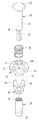
도 2는 본 발명의 일 실시예에 따른 내진 데크 인서트를 나타낸 분해사시도이다.
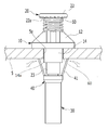
도 3은 본 발명의 일 실시예에 따른 내진 데크 인서트를 나타낸 단면도이다.
도 4는 본 발명의 일 실시예에 따른 내진 데크 인서트가 데크플레이트의 관통공을 통과하는 과정을 나타낸 개략도이다.
도 5는 본 발명의 일 실시예에 따른 내진 데크 인서트가 데크플레이트의 관통공을 통과한 상태를 나타낸 개략도이다.
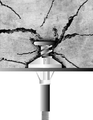
도 6a 및 6b는 지진에 의한 데크 인서트의 거동을 도식적으로 표현한 도면으로서 6a는 종래 데크 인서트이고, 6b는 본 발명의 일 실시예에 따른 내진 데크 인서트를 나타낸 도면이다.1 is a perspective view illustrating an anti-earthquake deck insert according to an embodiment of the present invention.
2 is an exploded perspective view showing an anti-earthquake deck insert according to an embodiment of the present invention.
3 is a cross-sectional view illustrating an anti-earthquake deck insert according to an embodiment of the present invention.
4 is a schematic view showing a process of passing an earthquake deck insert according to an embodiment of the present invention through a through hole of a deck plate.
5 is a schematic view showing a state in which an earthquake deck insert according to an embodiment of the present invention is passed through a through hole of a deck plate.
FIGS. 6A and 6B are diagrams showing a behavior of a deck insert due to an earthquake, in which FIG. 6A is a conventional deck insert, and FIG. 6B is an illustration of an earthquake deck insert according to an embodiment of the present invention.
이하, 첨부된 도면에 의거 본 발명을 설명하면 다음과 같다.Hereinafter, the present invention will be described with reference to the accompanying drawings.
도 1 내지 도 5에서 나타낸 것과 같이, 본 발명의 일 실시예에 따른 내진 데크 인서트는 건물의 슬라브용 데크플레이트(5)의 소정 관통공(5a)을 통해 앙카볼트(7, 전산볼트)를 설치하기 위한 것이다.1 to 5, an earthquake-proof deck insert according to an embodiment of the present invention includes an anchor bolt 7 (a computer bolt) installed through a predetermined through-
본 발명의 데크 인서트는 상면지지대(10)와, 가압핀(20)과, 볼트연결구(30)와, 저면지지대(40) 및 탄성체(50)를 포함한다.The deck insert of the present invention includes an
상기 상면지지대(10)는 상기 데크플레이트(5)의 상면에 배치되고 일측에 상기 관통공(5a)과 연통되는 제1관통공(11)이 형성되며 상면에 타설되는 콘크리트의 가압력이나 지진 등에 의해 파쇄된 콘크리트의 가압력에 저항하여 상기 가압핀(20)이 측방으로 기울어지는 것을 차단하는 가압저항부(12)가 마련되어 있다.The upper
그리고, 상기 상면지지대(10)는, 상기 데크플레이트(5)의 상면에 밀착되고 중앙에 상기 제1관통공(11)이 형성되며 상기 제1관통공(11) 테두리를 따라 상기 가압저항부(12)가 복수개 마련된 지지판(13) 및 상기 관통공(5a) 내에 배치되도록 상기 제1관통공(11)의 테두리에서 하향 연장되어 상기 지지판(13)이 상기 데크플레이트(5) 상면에서 유동되는 것을 방지하기 위해 지지하는 지지관체(14)가 마련되어 있다.The upper
여기서, 상기 가압저항부(12)는 상기 제1관통공(11)의 테두리에서 일정높이 상향 직립되고 상기 지지판(13)의 테두리에서는 상기 상향 직립되는 방향으로 상향 경사진 삼각형 경사판 구조로 되어 있다. Here, the
그리고, 상기 복수의 가압저항부(12)는 상기 제1관통공(11)의 테두리를 따라 등간격으로 이격되어 서로가 직각을 이루는 4조각으로 되어 있다.The plurality of pressing
그리고, 상기 각각의 가압저항부(12)는 상단면에 상기 탄성체(50)의 하단부가 안착되어 외측으로 이탈이 방지되도록 하방으로 오목하게 패인 안착홈(12a)이 마련되어 있다. Each of the pressure
그리고, 상기 지지관체(14)는 그 하단부가 데크플레이트(5)의 관통공(5a)을 관통한 상태로 일정길이 하향 돌출되는 길이를 갖는 하향연장부(14a)가 마련되어 있다.The
여기서, 상기 하향연장부(14a)는, 일례로, 조립이 완성된 본 발명의 데크 인서트가 상기 데크플레이트(5)에 장착되어 상기 지지관체(14)의 하향연장부(14a)가 데크플레이트(5)의 저면으로 일정길이 돌출된 상태가 되고, 또한, 저면지지대(40)의 떠받침부(41)가 상기 데크플레이트(5)의 저면에 탄성체(50)의 탄발력을 받고 밀착된 상태에서 아직 데크플레이트(5) 상으로 콘크리트 타설전인 시점일 때, 데크플레이트(5)의 하방에서 상기 펼쳐져 있는 복수의 떠받침부(41)들을 관통공(5a) 방향으로 자의 또는 타의에 의해 오무리게 될 경우에 상기 떠받침부(41)들은 상기 관통공(5a)으로 진입되기 전에 상기 하향연장부(14a)에 걸려 진입이 방지되도록 되어 있다.The downwardly extended
다시 말해서, 상기 하향연장부(14a)가 없다면 상기 오무라드는 떠받침부(41)는 별다른 저지없이 오무라들어 상기 관통공(5a)으로 진입된 후 탄성체(50)의 탄발력에 의해 데크플레이트(5) 상방으로 상승되어 결과적으로 상기 데크 인서트 전체가 데크플레이트(5)의 상방으로 이탈되어 장착이 해제되게 된다. In other words, if there is no downward extending
이는 의도치않게 떠받침부(41)가 외력에 의해 오무라들 경우 데크플레이트(5)에 대한 장착이 해제되면서 공사 전반에 차질이 생기게 될 수도 있으며, 또한, 자의에 의해 데크플레이트(5)에 장착되어 있는 데크 인서트를 이탈시키고자 할 경우에는 떠받침부(41)를 하방으로 일정길이 하향시킨 후 하향연장부(14a)의 저면으로 모운 후 상향 이탈시켜야 하는 이중 동작이 필요하기 때문에 단일 동작으로 떠받침부(41)를 모아서 이탈시키는 것과 비교하여 이탈이 어렵게 되도록 함으로써 예를 들어 도난 방지 등에 도움이 될 수 있다. This is because unintentional mounting of the
상기 가압핀(20)은 상기 제1관통공(11)을 관통하여 상측부가 상기 상면지지대(10)의 상방에 위치되고 하측부가 상기 관통공(5a) 하방으로 돌출되며 하단부 일측에 제1연결부(21)가 마련되어 있다.The
상기 가압핀(20)은 외주면에 상기 탄성체(50)가 감싸는 형상으로 배치되고 상단부에 상기 탄성체(50)의 상단부가 걸려 지지되도록 하는 대직경 원판재 형상의 버튼부(22)가 마련되어 있다. The
그리고, 상기 버튼부(22)는 타설 후 양생된 콘크리트와 맞물려 상기 가압핀(20)의 축회전이 방지되도록 저면 테두리를 따라 복수의 톱니 형상의 회전방지돌기(22a)가 마련되어 있다. The
여기서, 상기 가압핀(20)의 제1연결부(21)와 상기 볼트연결구(30)의 제2연결부(31)는 각각 서로가 나사 결합되도록 하는 나사산 구조로 되어 있다.The first connecting
그리고, 상기 가압핀(20)은 상기 상단부의 버튼부(22)와 하단부의 제1연결부(21) 사이에 원기둥 형상의 본체(23)가 마련되고, 상기 제1연결부(21)는 상기 본체(23)보다 직경이 작은 소직경 구조로 되어 상기 제1연결부(21)와 본체(23) 사이에 걸림턱(24)이 마련되어 있다. The
상기 볼트연결구(30)는 상기 가압핀(20)의 제1연결부(21)와 연결되는 제2연결부(31)가 상측에 마련되고 하측에 앙카볼트(7)와 연결되는 볼트연결부(32)가 마련되어 있다. The
그리고, 상기 볼트연결구(30)는, 원관체 형상으로 상기 제1연결부(21)가 삽입되어 나사 체결되도록 상단부 내주면에 나사산 구조의 상기 제2연결부(31)가 형성되고, 상기 볼트연결부(32)는 하단부 내주면에 상기 앙카볼트(7)가 나사 결합되도록 하는 나사산 구조로 되어 있다.The
그리고, 상기 제2연결부(31)와 볼트연결부(32) 사이에는 앙카볼트(7)의 나사 결합 정도(길이)를 조절하여 결과적으로 앙카볼트(7)에 연결되는 시설물의 하중에 선택적으로 적절히 대응할 수 있도록 상기 제2연결부(31) 및 볼트연결부(32)와 동일 나사 피치를 갖는 나사산부(33)가 마련되어 있다.The screw connection degree (length) of the anchor bolt 7 is adjusted between the second connecting
예를 들어,앙카볼트(7)에 연결되는 시설물의 하중이 작을 경우에는 앙카볼트(7)를 볼트연결부(32)에만 나합시키고, 시설물의 하중이 클 경우에는 볼트연결부(32)를 넘어 상기 나사산부(33)까지 나합시켜 선택적으로 적절히 시설물 하중에 대응할 수 있을 것이다. For example, when the load of the facilities connected to the anchor bolts 7 is small, the anchor bolts 7 are engaged only with the
상기 저면지지대(40) 상기 가압핀(20)과 볼트연결구(30) 사이에 고정되고 일측에 데크플레이트(5)의 저면을 떠받치는 떠받침부(41)가 마련되어 있다.The
여기서, 상기 저면지지대(40)는, 상기 볼트연결구(30)의 상단면에 안착되고 상기 가압핀(20)의 제1연결부(21)가 관통되는 링 형상으로, 상단 테두리를 따라 얇은 장방형 판재 형상의 상기 떠받침부(41)가 복수개 마련되며, 상기 떠받침부(41)의 인접 내측인 상기 저면지지대(40)의 상단면 내측 부위에 상기 가압핀(20)의 걸림턱(24)이 안착되도록 하는 걸림턱안착부(42)가 마련되어 있다. The
그리고, 상기 떠받침부(41)는 하단부가 상기 저면지지대(40)의 상단면에 연결되고 상단부가 일정높이 외향 경사진 구조로 되어 있다.The
그리고, 상기 복수개의 떠받침부(41)는 상기 저면지지대(40)의 상단 테두리를 따라 등간격으로 배치되는 4조각으로 이루어져 있다.In addition, the plurality of the
여기서, 상기 떠받침부(41)는 관통공(5a) 관통시 내측으로 오므라들었다가 관통공(5a)을 관통하고 나면 다시 펼쳐져서 그 상단부가 상기 데크플레이트(5)의 저면을 탄성적으로 떠받치는 역할을 수행한다.When the through-
상기 탄성체(50)는 상기 상면지지대(10)와 가압핀(20) 사이에 개재되어 상기 상면지지대(10)와 저면지지대(40)에 각각 탄발력을 제공하는 스프링 구조로 되어 있다. The
보다 상세하게, 상기 탄성체(50)는 상기 버튼부(22)의 하향 가압에 의해 압축되었다가 상기 버튼부(22)의 하향 가압력 해제시 상기 버튼부(22)를 상방으로 밀어내어 원상 복귀시키는 코일스프링 구조로 되어 있다.More specifically, the
그리고, 상기 탄성체(50)는 관통공(5a)에 본 발명의 데크 인서트의 설치가 완성되면 상면지지대(10)는 데크플레이트(5)의 상면을 탄성 가압하고 떠받침부(41)는 데크플레이트(5)의 저면을 탄성 가압하여 데크 인서트 전체가 견고히 지지될 수 있도록 탄성을 부여하는 역할을 수행한다.When the deck insert of the present invention is completed in the through
그리고, 상기 앙카볼트(7)를 통한 전기가 상기 데크플레이트(5)로 전달되는 것을 차단하기 위해 상기 본체(10)는 물론 고정너트(21)를 제외한 상면지지대(20)와 저면지지대(30) 및 상면지지대(40)를 플라스틱 등의 절연재질(플라스틱)로 제작할 수 있다.The upper and
미완성부호 60은 관통공(5a)의 내주면과 지지관체(14)의 외주면 사이에 형성되어 있는 완충틈새(60)를 나타낸 것이다.The
이러한 완충틈새(60)에 의해 데크플레이트(5)에 본 발명의 데크 인서트가 장착된 상태에서 콘크리트 타설 전 또는 타설 후에 상기 데크 인서트로 외력이 가해지는 경우, 상기 데크 인서트(지지관체(14))가 완충틈새(60) 사이의 공간에서 유동이 되어 외력에 의한 에너지가 곧바로 데크플레이트(5)로 전달되지 않아 결과적으로 데크플레이트(5)로의 직접적인 타격을 방지할 수 있게 됨은 물론 데크 인서트 자체에 대한 데크플레이트(5)의 반력도 방지할 수 있도록 하는 것이다. When the deck insert is attached to the
이러한 구성에 따른 본 발명의 일 실시예인 데크 인서트의 조립 과정을 살펴보면, 가압핀(20)의 본체(23) 외주면에 탄성체(50)를 장착하여 탄성체(50)의 상단부가 상기 버튼부(22)의 저면에 걸리도록 하고 상기 탄성체(50)의 하단부가 상면지지대(10)의 안착홈(12a)에 안착되도록 하여 상기 가압핀(20)을 상면지지대(10)의 제1관통공(11)으로 관통시킨다. The
그리고, 상면지지대(10)의 저면으로 돌출된 제1연결부(21) 외주로 상기 저면지지대(40)를 관통시킨 다음 볼트연결구(30)의 제2연결부(31)와 나사 결합시켜 본 발명의 데크 인서트의 조립을 완성한다.The
이렇게 조립이 완성된 본 발명의 데크 인서트의 설치 과정을 살펴보면, 우선 콘크리트 타설 전의 데크플레이트(5) 상방에서 그 관통공(5a)을 통해 상기 볼트연결구(30)를 하방으로 관통시킨다.The assembly process of the deck insert according to the present invention will now be described. First, the
이때, 상기 저면지지대(40)의 각 떠받침부(41)들이 지지관체(14)쪽으로 탄력있게 오므라들어 상기 관통공(5a)을 원활하게 통과할 수 있게 되고, 이렇게 관통공(5a)을 통과하게 되면 상기 각각의 떠받침부(41)들이 다시 탄발력에 의해 원상 복귀되면서 우산살 형상으로 펼쳐져 상기 데크플레이트(5)의 저면을 떠받친 상태가 된다.At this time, each of the
그리고, 이와 동시에 데크플레이트(5)의 상면에는 상기 상면지지대(10)의 지지판(13)이 밀착된 상태로 상기 본체(23) 외주부의 탄성체(50)가 상방의 버튼부(22)와 하방의 상면지지대(10) 사이에서 탄성 압축되어 결과적으로 상면지지대(10)와 저면지지대(40)에 탄성을 부여한 상태로 상기 데크플레이트(5)의 관통공(5a)에 탄성 지지된다. At the same time, the upper surface of the
이러한 상태에서 상기 데크플레이트(5)의 상면으로 콘크리트가 타설되어 상기 상면지지대(10)를 포함한 가압핀(20)까지 매립된 상태로 콘크리트가 양생되면 상기 버튼부(22)의 회전방지돌기(22a)가 콘크리트와 맞물려 가압핀(20)이 축 회전되는 일 없이 견고히 고정되게 된다. When the concrete is cured in a state where the concrete is laid on the upper surface of the
그리고, 차후 지진 등에 의해 콘크리트가 파쇄되면서 상기 가압핀(20)을 가압하게 되더라도 상면지지대(10)의 가압저항부(12)에 의해 가압핀(20)이 밀려 기울어지는 것을 방지할 수 있게 된다.(도면 6a, 6b 참조)It is also possible to prevent the
이렇게 하여, 본 발명의 내진 데크 인서트의 상측부는 데크플레이트(5)의 상방에서 콘크리트와 같이 굳어 고정되고, 상기 데크플레이트(5) 저면으로 노출된 볼트연결구(30)의 볼트연결부(32)를 통해 앙카볼트(7)를 나사 연결하여 이 앙카볼트(7)의 상단부가 상기 볼트연결부(32)에 연결 고정된 상태에서 상기 앙카볼트(7)의 하단부에 각종 전기기구나 덕트 등 필요한 시설물들을 연결하여 사용할 수 있게 되는 것이다. In this way, the upper portion of the earthquake-proof deck insert of the present invention is stiff and fixed like concrete at the upper part of the
위와 같이, 본 발명의 일 실시예에 따른 내진 데크 인서트는 데크플레이트의 상면에 배치되고 제1관통공과 가압저항부가 마련된 상면지지대와, 상기 제1관통공을 관통하고 제1연결부가 마련된 가압핀과, 상기 제1연결부와 연결되는 제2연결부와 앙카볼트와 연결되는 볼트연결부가 마련된 볼트연결구와, 데크플레이트의 저면을 떠받치는 떠받침부가 마련된 저면지지대와, 상기 상면지지대와 가압핀 사이에 개재되는 탄성체를 마련함으로써, 기본적으로 외력에 저항하여 앙카볼트가 기울어지는 등의 우려없이 견고하고 안정적으로 데크플레이트에 설치할 수 있게 되면서 안정성 향상을 도모할 수 있게 된다. As described above, the earthquake-resistant deck insert according to an embodiment of the present invention includes an upper surface support member disposed on an upper surface of a deck plate and having a first through hole and a pressure resistance portion, a pressing pin penetrating the first through- A bolt connecting hole having a bolt connecting part connected to the anchor bolt, a bottom supporting bar provided with a supporting part for supporting the bottom surface of the deck plate, and a bottom supporting part provided between the top supporting part and the pressing pin. By providing the elastic body, it is possible to mount on the deck plate firmly and stably without fear of tipping the anchor bolt against the external force, basically, and to improve the stability.
또한, 상면지지대와 저면지지대를 절연재질(플라스틱)로 제작하여 앙카볼트를 통한 전기가 상기 데크플레이트로 전달되는 것을 차단함으로써 안전사고 발생을 미연에 예방할 수 있음은 물론 플라스틱 등의 재질을 적용하여 원가절감도 꾀할 수 있게 된다.In addition, since the upper surface support member and the lower surface support member are made of an insulating material (plastic) to prevent electricity from being transmitted to the deck plate through the anchor bolt, safety accidents can be prevented, It is also possible to save money.
이상에서와 같이, 본 발명은 상기의 바람직한 실시예를 들어 설명하였으나, 이러한 실시예를 종래의 공지 기술과 단순히 조합 적용한 변형예는 물론 본 발명의 특허청구범위와 상세한 설명에서 본 발명이 속하는 기술 분야의 당업자가 용이하게 변경하여 이용할 수 있는 모든 기술들은 본 발명의 기술범위에 당연히 포함된다고 보아야 할 것이다. While the present invention has been particularly shown and described with reference to exemplary embodiments thereof, it is clearly understood that the same is by way of illustration and example only and is not to be taken by way of limitation, It should be understood that all of the techniques that can be easily changed and used by those skilled in the art are included in the technical scope of the present invention.
**도면의 주요부분에 대한 부호의 설명**
5 : 데크플레이트
5a : 관통공
7 : 앙카볼트
10 : 상면지지대
11 : 제1관통공
12 : 가압저항부
12a : 안착홈
13 : 지지판
14 : 지지관체
14a : 하향연장부
20 : 가압핀
21 : 제1연결부
22 : 버튼부
22a : 회전방지돌기
23 : 본체
24 : 걸림턱
30 : 볼트연결구
31 : 제2연결부
32 : 볼트연결부
33 : 나사산부
40 : 저면지지대
41 : 떠받침부
42 : 걸림턱안착부
50 : 탄성체
60 : 완충틈새DESCRIPTION OF REFERENCE NUMERALS
5:
7: Anchor bolt 10: Top surface support
11: first through hole 12: pressure resistance portion
12a: seating groove 13: supporting plate
14:
20: pressing pin 21: first connecting portion
22:
23: main body 24:
30: bolt connection port 31: second connection portion
32: bolt connection part 33:
40: bottom support 41:
42: retaining jaw mounting part 50: elastic body
60: buffer gap
Claims (1)
상기 데크플레이트의 상면에 배치되고 일측에 상기 관통공과 연통되는 제1관통공이 형성되며 상면에 타설되는 콘크리트의 가압력이나 지진 등에 의해 파쇄된 콘크리트의 가압력에 저항하는 가압저항부가 마련된 상면지지대;
상기 제1관통공을 관통하여 상측부가 상기 상면지지대의 상방에 위치되고 하측부가 상기 관통공 하방으로 돌출되며 하단부 일측에 제1연결부가 마련된 가압핀;
상기 가압핀의 제1연결부와 연결되는 제2연결부가 상측에 마련되고 하측에 앙카볼트와 연결되는 볼트연결부가 마련된 볼트연결구;
상기 가압핀과 볼트연결구 사이에 고정되고 일측에 데크플레이트의 저면을 떠받치는 떠받침부가 마련된 저면지지대; 및
상기 상면지지대와 가압핀 사이에 개재되어 상기 상면지지대와 저면지지대에 각각 탄발력을 제공하는 탄성체;
를 포함하고,
상기 상면지지대는,
상기 데크플레이트의 상면에 밀착되고 중앙에 상기 제1관통공이 형성되며 상기 제1관통공 테두리를 따라 상기 가압저항부가 복수개 마련된 지지판; 및
상기 제1관통공의 테두리에서 상기 관통공을 따라 하방으로 연장되는 지지관체;
를 포함하며,
상기 가압핀은 외주면에 상기 탄성체가 감싸는 형상으로 배치되고 상단부에 상기 탄성체의 상단부가 걸려 지지되도록 하는 대직경 판재 형상의 버튼부가 마련되고,
상기 가압저항부는 상기 제1관통공의 테두리에서 일정높이 상향 직립되고 상기 지지판의 테두리에서는 상기 상향 직립되는 방향으로 상향 경사진 경사판 구조로 되며,
상기 가압저항부는 상단면에 상기 탄성체의 하단부가 안착되도록 하방으로 오목하게 패인 안착홈이 마련되고,
상기 가압핀은 상기 상단부의 버튼부와 하단부의 제1연결부 사이에 원기둥 형상의 본체가 마련되고, 상기 제1연결부는 상기 본체보다 직경이 작은 소직경 구조로 되어 상기 제1연결부와 본체 사이에 걸림턱이 마련되며,
상기 저면지지대는, 상기 볼트연결구의 상단부에 안착되고 상기 가압핀의 제1연결부가 관통되는 링 형상으로, 상단 테두리를 따라 상기 떠받침부가 복수개 마련되며, 상기 떠받침부 내측인 상기 저면지지대의 상단부 내측 부위에 상기 가압핀의 걸림턱이 안착되도록 하는 걸림턱안착부가 마련되고,
상기 제2연결부와 볼트연결부 사이에는 앙카볼트의 나사 결합 정도(길이)를 조절하여 결과적으로 앙카볼트에 연결되는 시설물의 하중에 선택적으로 적절히 대응할 수 있도록 상기 제2연결부 및 볼트연결부와 동일 나사 피치를 갖는 나사산부가 마련되며,
상기 관통공의 내주면과 지지관체의 외주면 사이에는 상기 지지관체로 외력이 가해지는 경우 상기 지지관체가 소정길이 유동이 되어 상기 외력에 의한 에너지가 곧바로 상기 데크플레이트로 전달되지 못하게 하는 완충틈새가 마련된 것을 특징으로 하는 내진 데크 인서트.A deck insert for installing an anchor bolt through a predetermined through hole of a deck plate for a slab of a building,
An upper surface support member disposed on an upper surface of the deck plate and having a first through hole communicating with the through hole at one side thereof and having a pressing resistance portion for resisting pressing force of the concrete shattered by a pressing force or an earthquake of the concrete placed on the upper surface;
A pressing pin passing through the first through hole and having an upper portion located above the upper surface support, a lower portion protruding downwardly from the through hole, and a first connecting portion provided at a lower end of the lower portion;
A bolt connecting portion provided on the upper side with a second connecting portion connected to the first connecting portion of the pressing pin and having a bolt connecting portion connected to the anchor bolt on the lower side;
A lower surface support member fixed between the pressing pin and the bolt connecting member and having a support portion for supporting the bottom surface of the deck plate at one side; And
An elastic body interposed between the upper surface support and the pressing pin to provide an elastic force to the upper surface support and the lower surface support, respectively;
Lt; / RTI >
The upper surface support member,
A support plate which is in close contact with an upper surface of the deck plate and has the first through hole formed at the center thereof and has a plurality of pressing resistance portions along the frame through the first through hole; And
A support tube extending downward along the through-hole at an edge of the first through-hole;
/ RTI >
Wherein the pressing pin is disposed on an outer circumferential surface of the elastic body so as to surround the elastic body and the upper end of the elastic body is engaged with the upper end of the elastic body,
Wherein the pressure resistance portion has a slanting plate structure that is erected upward at a predetermined height from the rim of the first through hole and is inclined upward in the upright upright direction at the rim of the support plate,
Wherein the pressing resistance portion is provided with a receiving groove recessed downwardly so that a lower end of the elastic body is seated on an upper surface thereof,
Wherein the pressing pin has a cylindrical main body between the button portion of the upper end portion and the first connecting portion of the lower end portion and the first connecting portion has a small diameter structure smaller in diameter than the main body, A jaw is provided,
Wherein the bottom support base is a ring-shaped member that is seated on an upper end of the bolt connection port and through which the first connection portion of the presser pin passes, and a plurality of the retainer portions are provided along an upper edge, And an engaging jaw receiving portion for allowing the engaging jaw of the pressing pin to be seated on the inner side portion,
The length of screw connection of the anchor bolt may be adjusted between the second connection portion and the bolt connection portion so that the same screw pitch as that of the second connection portion and the bolt connection portion may be appropriately matched to the load of the facility connected to the anchor bolt Respectively,
A buffer gap is formed between the inner circumferential surface of the through-hole and the outer circumferential surface of the support tube to prevent the energy of the external force from being directly transmitted to the deck plate when the support tube has an external force applied thereto, Features an earthquake deck insert.
Priority Applications (1)
| Application Number | Priority Date | Filing Date | Title |
|---|---|---|---|
| KR1020170154538A KR102000933B1 (en) | 2017-11-20 | 2017-11-20 | Earthquake-proof deck insert |
Applications Claiming Priority (1)
| Application Number | Priority Date | Filing Date | Title |
|---|---|---|---|
| KR1020170154538A KR102000933B1 (en) | 2017-11-20 | 2017-11-20 | Earthquake-proof deck insert |
Related Parent Applications (1)
| Application Number | Title | Priority Date | Filing Date |
|---|---|---|---|
| KR1020170024520 Division | 2017-02-24 |
Publications (2)
| Publication Number | Publication Date |
|---|---|
| KR20180098115A true KR20180098115A (en) | 2018-09-03 |
| KR102000933B1 KR102000933B1 (en) | 2019-10-01 |
Family
ID=63601074
Family Applications (1)
| Application Number | Title | Priority Date | Filing Date |
|---|---|---|---|
| KR1020170154538A Active KR102000933B1 (en) | 2017-11-20 | 2017-11-20 | Earthquake-proof deck insert |
Country Status (1)
| Country | Link |
|---|---|
| KR (1) | KR102000933B1 (en) |
Citations (3)
| Publication number | Priority date | Publication date | Assignee | Title |
|---|---|---|---|---|
| KR19990004739A (en) | 1997-06-30 | 1999-01-25 | 윤종용 | Air conditioner outdoor unit |
| KR20120081748A (en) * | 2011-01-12 | 2012-07-20 | 상명엔프라(주) | Ceiling structure supports for inseret |
| KR101249305B1 (en) * | 2013-02-15 | 2013-04-03 | 정갑희 | A insert bolt having a structure of preventing rotation |
-
2017
- 2017-11-20 KR KR1020170154538A patent/KR102000933B1/en active Active
Patent Citations (3)
| Publication number | Priority date | Publication date | Assignee | Title |
|---|---|---|---|---|
| KR19990004739A (en) | 1997-06-30 | 1999-01-25 | 윤종용 | Air conditioner outdoor unit |
| KR20120081748A (en) * | 2011-01-12 | 2012-07-20 | 상명엔프라(주) | Ceiling structure supports for inseret |
| KR101249305B1 (en) * | 2013-02-15 | 2013-04-03 | 정갑희 | A insert bolt having a structure of preventing rotation |
Also Published As
| Publication number | Publication date |
|---|---|
| KR102000933B1 (en) | 2019-10-01 |
Similar Documents
| Publication | Publication Date | Title |
|---|---|---|
| US9097001B2 (en) | Concrete anchor | |
| US20070220815A1 (en) | Seismic isolation access floor assembly | |
| KR101337570B1 (en) | Construction method for addition pile | |
| KR101885992B1 (en) | Supporter for slab form of concrete structure | |
| KR101499111B1 (en) | Hybrid Foundation For Water Tank | |
| KR20140097752A (en) | Lower support of sectional dome structure | |
| KR101119852B1 (en) | Double bottom panel structure | |
| KR101920836B1 (en) | U bolt type fixture unit of construction material | |
| KR101713408B1 (en) | Steel rest including insert part | |
| JPS639622Y2 (en) | ||
| KR20090010031U (en) | Ceiling frame structure | |
| KR101469746B1 (en) | Insert structure body for anchor bolt | |
| JP5386214B2 (en) | Foundation structure | |
| KR101677671B1 (en) | Clumped access floor having earthquake-resistant coreframe | |
| KR20130001712A (en) | Pipe stands | |
| KR102000933B1 (en) | Earthquake-proof deck insert | |
| JP2014074488A (en) | Clearance management tool | |
| JP4999216B1 (en) | Basic block for earthquake-proof evacuation room | |
| JP2015094426A (en) | Base isolation stand and base isolation device using the same | |
| CN209837468U (en) | Anti-sliding connection structure of concrete main beam and secondary beam | |
| CN216690328U (en) | Fixing and supporting device for assembly type building | |
| KR20210115124A (en) | Anchoring inserts | |
| KR101063848B1 (en) | Fixture for Access Floor | |
| KR200375139Y1 (en) | Lower Part Fixing Structure of Gang Form | |
| KR200384367Y1 (en) | A support pipe for construction |
Legal Events
| Date | Code | Title | Description |
|---|---|---|---|
| A107 | Divisional application of patent | ||
| A201 | Request for examination | ||
| P11-X000 | Amendment of application requested |
St.27 status event code: A-2-2-P10-P11-nap-X000 |
|
| P13-X000 | Application amended |
St.27 status event code: A-2-2-P10-P13-nap-X000 |
|
| PA0107 | Divisional application |
St.27 status event code: A-0-1-A10-A18-div-PA0107 St.27 status event code: A-0-1-A10-A16-div-PA0107 |
|
| PA0201 | Request for examination |
St.27 status event code: A-1-2-D10-D11-exm-PA0201 |
|
| R15-X000 | Change to inventor requested |
St.27 status event code: A-3-3-R10-R15-oth-X000 |
|
| R16-X000 | Change to inventor recorded |
St.27 status event code: A-3-3-R10-R16-oth-X000 |
|
| E902 | Notification of reason for refusal | ||
| PE0902 | Notice of grounds for rejection |
St.27 status event code: A-1-2-D10-D21-exm-PE0902 |
|
| PG1501 | Laying open of application |
St.27 status event code: A-1-1-Q10-Q12-nap-PG1501 |
|
| AMND | Amendment | ||
| P11-X000 | Amendment of application requested |
St.27 status event code: A-2-2-P10-P11-nap-X000 |
|
| P13-X000 | Application amended |
St.27 status event code: A-2-2-P10-P13-nap-X000 |
|
| E601 | Decision to refuse application | ||
| PE0601 | Decision on rejection of patent |
St.27 status event code: N-2-6-B10-B15-exm-PE0601 |
|
| X091 | Application refused [patent] | ||
| AMND | Amendment | ||
| P11-X000 | Amendment of application requested |
St.27 status event code: A-2-2-P10-P11-nap-X000 |
|
| P13-X000 | Application amended |
St.27 status event code: A-2-2-P10-P13-nap-X000 |
|
| PX0901 | Re-examination |
St.27 status event code: A-2-3-E10-E12-rex-PX0901 |
|
| PX0701 | Decision of registration after re-examination |
St.27 status event code: A-3-4-F10-F13-rex-PX0701 |
|
| X701 | Decision to grant (after re-examination) | ||
| GRNT | Written decision to grant | ||
| PR0701 | Registration of establishment |
St.27 status event code: A-2-4-F10-F11-exm-PR0701 |
|
| PR1002 | Payment of registration fee |
St.27 status event code: A-2-2-U10-U11-oth-PR1002 Fee payment year number: 1 |
|
| PG1601 | Publication of registration |
St.27 status event code: A-4-4-Q10-Q13-nap-PG1601 |
|
| FPAY | Annual fee payment |
Payment date: 20220531 Year of fee payment: 4 |
|
| PR1001 | Payment of annual fee |
St.27 status event code: A-4-4-U10-U11-oth-PR1001 Fee payment year number: 4 |
|
| PR1001 | Payment of annual fee |
St.27 status event code: A-4-4-U10-U11-oth-PR1001 Fee payment year number: 5 |
|
| PR1001 | Payment of annual fee |
St.27 status event code: A-4-4-U10-U11-oth-PR1001 Fee payment year number: 6 |
|
| R18-X000 | Changes to party contact information recorded |
St.27 status event code: A-5-5-R10-R18-oth-X000 |
|
| R18-X000 | Changes to party contact information recorded |
St.27 status event code: A-5-5-R10-R18-oth-X000 |
|
| R18 | Changes to party contact information recorded |
Free format text: ST27 STATUS EVENT CODE: A-5-5-R10-R18-OTH-X000 (AS PROVIDED BY THE NATIONAL OFFICE) |
|
| R18-X000 | Changes to party contact information recorded |
St.27 status event code: A-5-5-R10-R18-oth-X000 |
|
| PN2301 | Change of applicant |
St.27 status event code: A-5-5-R10-R13-asn-PN2301 St.27 status event code: A-5-5-R10-R11-asn-PN2301 |
|
| R11 | Change to the name of applicant or owner or transfer of ownership requested |
Free format text: ST27 STATUS EVENT CODE: A-5-5-R10-R11-ASN-PN2301 (AS PROVIDED BY THE NATIONAL OFFICE) |
|
| R13 | Change to the name of applicant or owner recorded |
Free format text: ST27 STATUS EVENT CODE: A-5-5-R10-R13-ASN-PN2301 (AS PROVIDED BY THE NATIONAL OFFICE) |
|
| PN2301 | Change of applicant |
St.27 status event code: A-5-5-R10-R13-asn-PN2301 St.27 status event code: A-5-5-R10-R11-asn-PN2301 |
|
| R11 | Change to the name of applicant or owner or transfer of ownership requested |
Free format text: ST27 STATUS EVENT CODE: A-5-5-R10-R11-ASN-PN2301 (AS PROVIDED BY THE NATIONAL OFFICE) |
|
| R13 | Change to the name of applicant or owner recorded |
Free format text: ST27 STATUS EVENT CODE: A-5-5-R10-R13-ASN-PN2301 (AS PROVIDED BY THE NATIONAL OFFICE) |
|
| PN2301 | Change of applicant |
St.27 status event code: A-5-5-R10-R13-asn-PN2301 St.27 status event code: A-5-5-R10-R11-asn-PN2301 |
|
| R11 | Change to the name of applicant or owner or transfer of ownership requested |
Free format text: ST27 STATUS EVENT CODE: A-5-5-R10-R11-ASN-PN2301 (AS PROVIDED BY THE NATIONAL OFFICE) |
|
| R13 | Change to the name of applicant or owner recorded |
Free format text: ST27 STATUS EVENT CODE: A-5-5-R10-R13-ASN-PN2301 (AS PROVIDED BY THE NATIONAL OFFICE) |