KR20180087650A - Skeleton structure for furniture - Google Patents
Skeleton structure for furniture Download PDFInfo
- Publication number
- KR20180087650A KR20180087650A KR1020170011941A KR20170011941A KR20180087650A KR 20180087650 A KR20180087650 A KR 20180087650A KR 1020170011941 A KR1020170011941 A KR 1020170011941A KR 20170011941 A KR20170011941 A KR 20170011941A KR 20180087650 A KR20180087650 A KR 20180087650A
- Authority
- KR
- South Korea
- Prior art keywords
- connector
- frame
- horizontal frame
- coupling
- vertical frame
- Prior art date
Links
Images


Classifications
-
- A—HUMAN NECESSITIES
- A47—FURNITURE; DOMESTIC ARTICLES OR APPLIANCES; COFFEE MILLS; SPICE MILLS; SUCTION CLEANERS IN GENERAL
- A47B—TABLES; DESKS; OFFICE FURNITURE; CABINETS; DRAWERS; GENERAL DETAILS OF FURNITURE
- A47B47/00—Cabinets, racks or shelf units, characterised by features related to dismountability or building-up from elements
-
- A—HUMAN NECESSITIES
- A47—FURNITURE; DOMESTIC ARTICLES OR APPLIANCES; COFFEE MILLS; SPICE MILLS; SUCTION CLEANERS IN GENERAL
- A47B—TABLES; DESKS; OFFICE FURNITURE; CABINETS; DRAWERS; GENERAL DETAILS OF FURNITURE
- A47B96/00—Details of cabinets, racks or shelf units not covered by a single one of groups A47B43/00 - A47B95/00; General details of furniture
- A47B96/06—Brackets or similar supporting means for cabinets, racks or shelves
- A47B96/066—Supporting means received within an edge of the shelf
-
- A—HUMAN NECESSITIES
- A47—FURNITURE; DOMESTIC ARTICLES OR APPLIANCES; COFFEE MILLS; SPICE MILLS; SUCTION CLEANERS IN GENERAL
- A47B—TABLES; DESKS; OFFICE FURNITURE; CABINETS; DRAWERS; GENERAL DETAILS OF FURNITURE
- A47B96/00—Details of cabinets, racks or shelf units not covered by a single one of groups A47B43/00 - A47B95/00; General details of furniture
- A47B96/14—Bars, uprights, struts, or like supports, for cabinets, brackets, or the like
- A47B96/1433—Hollow members
Abstract
Description
본 발명은 가구용 골격 조립 구조에 관한 것으로서, 특히 가구용 구조물의 골격을 이루기 위해 세워져 설치되는 수직프레임에 다수의 수평프레임을 연결하여 설치할 때 작업성이 간편하면서도 견고하게 연결되어 쉽게 파손되지 않는 내구성이 있고 품질과 생산성을 향상시킬 수 있는 가구용 골격 조립 구조에 관한 것이다.
The present invention relates to a skeleton structure for furniture, and more particularly, it relates to a structure for assembling a skeleton for furniture, in which a plurality of horizontal frames are connected to a vertical frame erected to form a skeleton of a furniture structure, And more particularly, to a skeletal structure for furniture which can improve quality and productivity.
일반적으로 가구는 철제를 이용한 가구와 목재를 이용한 가구로 분리되며, 가정에서 사용하는 장농, 옷장 외에 싱크대와 수납장 등으로 구성되는 주방용 가구, 사무용으로 사용되는 캐비넷, 파일박스, 월 캐비넷, 도면함, 공구함, 책장 등의 가구가 있으며, 또한 상품 진열을 위해 많이 사용하는 진열대도 있다.In general, the furniture is divided into furniture made of iron and furniture made of wood. In addition to the household wardrobe and closet, there are kitchen furniture including a sink and a cabinet, a cabinet used for office use, a file box, a wall cabinet, There are furniture such as tool boxes and bookshelves, and there are shelves that are used for displaying goods.
이러한 가구들은 대부분 세워져 설치되는 수직프레임에 수평프레임을 가로방향이나 세로방향으로 연결하여 가구의 골격을 형성하고 있다.Most of these furniture are formed by vertical frames, which are installed vertically and horizontally or vertically.
이와 같이 조립식으로 가구의 골격을 형성하는 선행기술로는 아래의 특허문헌에 개시된 대한민국 공개실용신안공보 공개번호 20-2014-0005694호(2014.11.06.공개)의 "진열대 조립용 연결구"(이하 '선행기술 1'이라 칭한다)가 있다.As prior arts for forming the framework of the furniture in such a manner as described above, there are a "connector for assembling a shelf" (hereinafter referred to as " connector for assembling a shelf ") of Korean Utility Model Publication No. 20-2014-0005694 Quot; Prior Art 1 ").
상기 선행기술 1은 진열대의 뼈대를 구성하는 사각프레임들을 서로 연결 고정하는 연결구를 구성함에 있어서, 육면체 형상의 연결구몸체; 상기 연결구몸체의 육면 중 적어도 두 개 이상의 면에서 돌출 형성되되 연결구몸체 보다 작은 크기를 갖고 상기 사각프레임에 끼워지는 사각 형상의 내부 중공형 관삽입부; 관삽입부 사이에서 관삽입부들과 간격을 두고 상기 연결구몸체에 일체로 고정되며, 진열대 조립시 받침판을 지지하는 안착편;을 포함하여 구성된 것이다.In the prior art 1, a connecting port for connecting and fixing the rectangular frames constituting the frame of the shelf is formed, the connecting body including a hexahedron; A rectangular hollow tube insertion part protruding from at least two sides of the hexagon of the connector body and having a size smaller than that of the connector body and fitted in the square frame; And a seat piece integrally fixed to the connector body at an interval from the tube insertion parts between the tube insertion parts and supporting the support plate when assembling the display case.
상기 선행기술 1은 두개의 면 이상에 관삽입구가 구비된 연결구몸체를 이용하여 사각프레임들을 종,횡으로 연속 연결하여 여러 칸의 복층으로 구획되는 진열대로 조립할 수 있도록 한 것이다. 그런데, 상기 선행기술 1은 연결구몸체의 관삽입부에 사각프레임들을 단순히 끼워 조립한 것이므로 조립 후 외측으로 충격이 가해질 경우 사각프레임이 연결구몸체의 관삽입부에서 쉽게 빠져 무너질 우려가 있어 내구성이 약한 문제점이 있다.In the prior art 1, the rectangular frame is continuously connected longitudinally and transversely by using a connecting body having a tube insertion port on two or more surfaces, so that the rectangular frame can be assembled into a plurality of shelves divided into multiple layers. However, in the prior art 1, when the impact is applied to the outer side after assembling, the square frame easily slips off the tube insertion portion of the connector body because the square frame is simply assembled to the tube insertion portion of the connector body. .
그리고 포스트에 끼워져 체결되는 선반받침대의 부위는 양단과 일자를 유지하는 얇은 두께인 상태 그대로 포스트에 고정볼트로 조립되는 것이므로 선반에 놓인 물건의 하중이 선반받침대에 가해질 경우 얇은 체결부위가 쉽게 파손되며, 또한 포스트 양면에서 서로 마주보도록 2개의 선반받침대를 조립하였을 때 양쪽 선반받침대의 끝단이 쉽게 벌어지면서 지지력이 떨어지는 문제점이 있었다.
Since the part of the shelf bracket which is inserted and fastened to the post is assembled with the fixing bolt on the post in a state of thin thickness maintaining both ends and the date, when the load of the article placed on the shelf is applied to the rack bracket, In addition, when two shelf brackets are assembled so as to face each other on both sides of the post, the ends of both shelf brackets are easily widened and the bearing force is lowered.
따라서 본 발명은 상기와 같은 종래의 기술에서 발생하는 제반 문제점을 해결하기 위해서 제안된 것으로서 본 발명은 수직프레임에 다수의 수평프레임을 연결하여 설치할 때 작업성이 간편하면서도 견고하게 연결되어 쉽게 파손되지 않는 내구성이 있고 품질과 생산성을 향상시킬 수 있는 가구용 골격 조립 구조를 제공하기 위한 것이다.
SUMMARY OF THE INVENTION Accordingly, the present invention has been made keeping in mind the above problems occurring in the prior art, and it is therefore an object of the present invention to provide an apparatus and a method for connecting a plurality of horizontal frames to a vertical frame, And to provide a skeletal structure for furniture which is durable and can improve quality and productivity.
이에 본 발명은 이와 같은 종래의 문제점을 해결하기 위한 것으로 본 발명의 목적은 수직프레임과 수평프레임으로 가구용 골격을 구성함에 있어서, 사각파이프로 구성되어 세워져 설치되며, 길이 방향을 따라 사방의 면에 복수의 체결공이 일정 간격으로 다수 형성된 수직프레임; 상기 복수의 체결공에 일치되는 나사홀과 기준핀이 한 조를 이루도록 부착면에 구비되어 수직프레임의 4면 중 2면 이상에 부착되며, 양 측면에 결합돌기가 구비된 연결구; 상부에서 연결구에 끼워 걸 수 있도록 양쪽 단에 개방부가 구비되고, 상기 결합돌기에 끼워져 걸리는 결합공이 양 측벽에 구비된 수평프레임; 으로 구성됨으로써 상기 목적을 효과적으로 달성할 수 있다.SUMMARY OF THE INVENTION Accordingly, the present invention has been made keeping in mind the above problems occurring in the prior art, and an object of the present invention is to provide a vertical frame and a horizontal frame for constructing a furniture frame, A vertical frame formed with a plurality of fastening holes at regular intervals; A connecting hole provided on the mounting surface so as to form a pair of screw holes and reference pins corresponding to the plurality of fastening holes and attached to at least two of four sides of the vertical frame and having coupling projections on both sides; A horizontal frame provided with openings at both ends thereof so as to be able to be inserted into the connector at an upper portion thereof and having engagement holes which are engaged with the engagement protrusions, The above object can be achieved effectively.
이러한 본 발명은 수직프레임과 수평프레임으로 조립식 가구의 틀을 이루는 골격을 구성하고자 수직프레임에 부착되는 연결구를 매개체로 하여 수평프레임을 조립할 때 수평프레임 양단의 개방부를 이용하여 연결구 상부에서 아래로 내려 연결구에 조립하면 되는 것이므로 종래처럼 양쪽 수직프레임 간의 간격을 벌리지 않고서도 수평프레임을 신속 간편하게 조립할 수 있고, 분리할 때도 신속 간편하여 작업성이 매우 좋은 효과가 있다.In order to construct a frame that forms a frame of a prefabricated furniture with a vertical frame and a horizontal frame, when the horizontal frame is assembled by using a connector attached to the vertical frame, the open frame at both ends of the horizontal frame is used to lower the connector It is possible to assemble the horizontal frame quickly and easily without widening the gap between the two vertical frames as in the conventional art.
또한, 연결구에 록킹수단이 구비된 경우에는 록킹수단이 연결구에 조립된 수평프레임의 고정핀을 보다 견고하게 걸어주어서 외부에서 충격이나 물리적 힘이 가해지더라도 수평프레임이 연결구에서 쉽게 분리되지 않으므로 제품의 내구성과 품질을 향상시킬 수 있는 것이다.
In addition, when the locking means is provided in the connecting port, the locking means hermetically fixes the fixing pin of the horizontal frame assembled in the connecting port, so that even if impact or physical force is externally applied, the horizontal frame is not easily separated from the connecting port. And quality can be improved.
도 1 은 본 발명의 가구용 골격이 조립되는 상태를 일례로 보인 정면도.
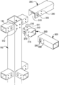
도 2a 는 본 발명의 가구용 골격을 일부 분해하여 보인 사시도.
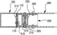
도 2b 는 도 2a의 수직프레임에 수평프레임이 조립된 상태를 보인 평단면도.
도 3a 는 본 발명의 가구용 골격을 다른 실시예로 보인 일부 분해사시도.
도 3b 는 도3a 의 수직프레임에 수평프레임이 조립된 상태를 보인 평단면도.BRIEF DESCRIPTION OF THE DRAWINGS Fig. 1 is a front view of an embodiment of a furniture skeleton according to the present invention. Fig.
FIG. 2A is a perspective view showing the furniture skeleton of FIG.
FIG. 2B is a plan sectional view showing a state in which a horizontal frame is assembled in the vertical frame of FIG. 2A. FIG.
FIG. 3A is a partially exploded perspective view showing a furniture skeleton according to another embodiment of the present invention; FIG.
FIG. 3B is a plan sectional view showing a state in which a horizontal frame is assembled in the vertical frame of FIG. 3A. FIG.
이하에서 본 발명의 상기 목적을 달성할 수 있는 기술 구성 및 작용을 바람직한 실시 예로 첨부한 도면에 의해 구체적으로 설명하면 다음과 같다.BEST MODE FOR CARRYING OUT THE INVENTION Hereinafter, description will be made in detail of preferred embodiments of the present invention with reference to the accompanying drawings.
도 1 은 본 발명의 가구용 골격이 조립되는 상태를 일례로 보인 정면도이고, 도 2a 는 본 발명의 가구용 골격을 일부 분해하여 보인 사시도이며, 도 2b 는 도 2a의 수직프레임에 수평프레임이 조립된 상태를 보인 평단면도이고, 도 3a 는 본 발명의 가구용 골격을 다른 실시예로 보인 일부 분해사시도이며, 도 3b 는 도3a 의 수직프레임에 수평프레임이 조립된 상태를 보인 평단면도이다.FIG. 2 is a perspective view illustrating a state in which the horizontal frame is assembled to the vertical frame of FIG. 2A; FIG. 2 is a perspective view of the furniture frame of FIG. FIG. 3A is a partially exploded perspective view showing a furniture frame according to another embodiment of the present invention, and FIG. 3B is a horizontal sectional view showing a state in which a horizontal frame is assembled in the vertical frame of FIG.
이와 같은 본 발명은 수직프레임과 수평프레임으로 가구용 골격을 구성함에 있어서, 사각파이프로 구성되어 세워져 설치되며, 길이 방향을 따라 사방의 면에 복수의 체결공(110)이 일정 간격으로 다수 형성된 수직프레임(100); 상기 복수의 체결공(110)에 일치되는 나사홀(211)과 기준핀(212)이 한 조를 이루도록 부착면(210)에 구비되어 수직프레임(100)의 4면 중 2면 이상에 부착되며, 양 측면에 결합돌기(213)가 구비된 연결구(200); 상부에서 연결구(200)에 끼워 걸 수 있도록 양쪽 단에 개방부(310)가 구비되고, 상기 결합돌기(213)에 끼워져 걸리는 결합공(320)이 양 측벽에 구비된 수평프레임(300);으로 구성된 것을 특징으로 한다.The vertical frame and the horizontal frame form a vertical frame and a horizontal frame. The vertical frame and the horizontal frame form a rectangular frame. The vertical frame and the horizontal frame form a rectangular frame. (100); And is attached to at least two of four sides of the
도면중 미설명부호 (215)는 연결구에 형성된 볼트공이고, (330)은 수평프레임에 형성된 볼트공이며, (410)은 수직프레임과 연결구를 결합하기 위한 볼트이고, (420)은 수평프레임과 연결구를 조립하기 위한 볼트이다.
이러한 본 발명은 장농, 옷장 외에 싱크대와 수납장 같은 주방용 가구, 캐비넷, 파일박스, 월 캐비넷, 도면함, 공구함, 책장과 같은 사무용 가구와 같이 수직프레임에 수평프레임을 가로 방향이나 세로 방향으로 연결하여 가구의 골격을 형성하는 것은 종래와 마찬가지이다.The present invention can be applied to a vertical frame such as office furniture such as kitchen furniture such as a sink and a cabinet, a cabinet, a file box, a wall cabinet, a drawer box, The formation of the framework of the furniture is the same as the conventional one.
그러나 본 발명에서의 특징은 수직프레임에 수평프레임을 연결할 시 작업성이 간편하면서도 견고하게 연결되어 쉽게 파손되지 않으면서 내구성이 있고 품질과 생산성을 향상시킬 수 있도록 한 것이다.However, the feature of the present invention is that when the horizontal frame is connected to the vertical frame, the workability is simple but firmly connected, so that it is not easily broken and is durable, and the quality and productivity can be improved.
즉, 본 발명은 수직프레임(100)과 그 수직프레임(100)에 부착되는 연결구(200) 및 연결구(200)에 의해 수직프레임(100)에 횡방향으로 조립되는 수평프레임(300)으로 구성된다.That is, the present invention comprises a
여기서 상기 수직프레임(100)은 사각파이프로 구성하고 사방의 면에 길이 방향을 따라 복수의 체결공(110)을 일정 간격으로 다수 형성하였다.Here, the
따라서 본 발명에서는 수직프레임(100)과 수평프레임(300)을 결합하고자 할 경우에는 우선 연결구(200)의 부착면(210)을 수직프레임(100)에 밀착시켜 즉, 연결구(200)에 구비된 기준핀(212)을 수직프레임(100)에 형성된 다수의 체결공(110) 중 아래쪽에 위치된 체결공(110)에 끼워주면 연결구(200)의 나사홀(211)은 수직프레임(100)의 위쪽 체결공(110)과 일치된 상태를 유지하기 때문에 이에 볼트(410)를 나사홀(211)과 체결공(110)에 관통되게 체결하여 주면 연결구(200)는 수직프레임(100)에 결합된다.Therefore, in the present invention, when the
즉, 상기 기준핀(212)이 먼저 삽입되어 위치를 잡아주면 나머지 나사홀(211)과 체결공(110)이 자연적으로 일치되기 때문에 작업자가 나사홀(211)과 체결공(110)을 일일이 맞춰줄 필요가 없어 그만큼 체결작업을 보다 신속하게 할 수 있다. That is, when the
이렇게 수직프레임(100)에 연결구(200)를 조립한 이후에는 수평프레임(300)을 연결구(200)에 결합하는데 상기 수평프레임(300)에는 양쪽 단에 개방부(310)가 구비되어 있기 때문에 즉, 수평프레임(300)을 개방부(310)를 이용하여 연결구(200)의 상부에서 아래로 내려 조립하여 수평프레임(300)의 결합공(320)속으로 연결구(200)의 결합돌기(213)가 끼워지게 하면 수평프레임(300)은 연결구(200)에 의해 수직프레임(100)에 밀착된 상태로 가조립된다.After assembling the
이처럼 연결구(200)의 결합돌기(213)와 수평프레임(100)의 결합공(320)에 의해 수평프레임(100)을 가조립시키면 연결구(200)의 볼트공(215)과 수평프레임(300)의 볼트공(330)이 서로 일치되는 것이고, 이에 볼트(420)를 체결하면 연결구(200)와 수평프레임(300)은 견고하게 서로 조립된다.When the
그리고 도3a, 3b 는 본 발명의 다른 실시 예를 도시한 것으로서 연결구(200)의 양 측면에 돌기공(214)을 형성하고, 양쪽 결합돌기(213)는 스프링(220)의 장력을 받아 연결구(200)의 돌기공(214)에서 출몰되도록 연결구(200) 내에 설치하였다.3A and 3B illustrate another embodiment of the present invention in which the
즉, 수직프레임(100)에 연결구(200)를 조립한 상태에서 수평프레임(300)을 개방부(310)를 이용하여 연결구(200)의 상부에서 아래로 내려 주면 스프링(220)의 장력을 받는 결합돌기(213)는 수평프레임(300)에 접촉되면 스프링(220)이 수축되면서 돌기공(214)속으로 밀려 들어가는 것이고, 결합돌기(213)와 결합공(320)이 일치되면 수축되었던 스프링(220)이 탄발되면서 결합돌기(213)를 밀어냄에 따라 결합돌기(213)가 결합공(320)을 통해 외측으로 돌출되면서 수평프레임(300)은 결합구(200)에 가조립된 상태를 유지하는 것이고, 이후 볼트(420)를 수평프레임(300)의 볼트공(330)과 연결구(200)의 볼트공(215)에 관통되게 체결하면 수평프레임(300)과 연결구(200)는 견고하게 조립된다.
That is, when the
100 : 수직프레임 110 : 체결공
200 : 연결구 210 : 부착면
211 : 나사홀 212 : 기준핀
213 : 결합돌기 214 : 돌기공
215,330 :볼트공 220 : 스프링
300 : 수평프레임 310 : 개방부
320 : 결합공 410,420 : 볼트100: vertical frame 110: fastening hole
200: connector 210: mounting surface
211: screw hole 212: reference pin
213: engaging projection 214:
215,330: Bolt hole 220: Spring
300: horizontal frame 310: opening
320:
Claims (2)
사각파이프로 구성되어 세워져 설치되며, 길이 방향을 따라 사방의 면에 복수의 체결공(110)이 일정 간격으로 다수 형성된 수직프레임(100);
상기 복수의 체결공(110)에 일치되는 나사홀(211)과 기준핀(212)이 한 조를 이루도록 부착면(210)에 구비되어 수직프레임(100)의 4면 중 2면 이상에 부착되며, 양 측면에 결합돌기(213)가 구비된 연결구(200);
상부에서 연결구(200)에 끼워 걸 수 있도록 양쪽 단에 개방부(310)가 구비되고, 상기 결합돌기(213)에 끼워져 걸리는 결합공(320)이 양 측벽에 구비된 수평프레임(300);
으로 구성되어 수평프레임(300)을 위에서 아래로 내려 끼우기만 하면 양쪽 수직프레임(100)들과 신속 간편하게 연결되도록 한 것을 특징으로 하는 가구용 골격 조립구조.
In constructing the furniture skeleton with the vertical frame and the horizontal frame,
A vertical frame 100 constructed and arranged as a square pipe and having a plurality of fastening holes 110 formed at regular intervals on the four sides along the longitudinal direction;
And is attached to at least two of four sides of the vertical frame 100 provided on the attachment surface 210 so as to form a pair of screw holes 211 and a reference pin 212 corresponding to the plurality of fastening holes 110 A connector 200 having coupling projections 213 on both sides thereof;
A horizontal frame 300 provided with openings 310 at both ends thereof so as to be able to be inserted into the connector 200 at the upper portion thereof and having coupling holes 320 fitted to the coupling protrusions 213 and provided on both side walls;
Wherein the horizontal frame (300) is easily and quickly connected to both the vertical frames (100) only when the horizontal frame (300) is pushed downward from above.
연결구(200)는 양 측면에 돌기공(214)을 형성하고,
양쪽 결합돌기(213)는 스프링(220)의 장력을 받아 연결구(200)의 돌기공(214)에서 출몰되도록 연결구(200) 내에 설치하여
수평프레임(300)의 결합공(320)이 탄력적으로 출물되는 결합돌기(213)에 끼워지면서 수평프레임(300)이 연결구(200)에 조립되게 한 것을 특징으로 하는 가구용 골격 조립구조.The method according to claim 1,
The connector 200 has a pore 214 on both sides thereof,
Both the coupling protrusions 213 are installed in the coupling hole 200 to receive the tension of the spring 220 and protrude and retract from the hole 214 of the coupling hole 200
Wherein the horizontal frame (300) is assembled to the connector (200) by fitting the coupling hole (320) of the horizontal frame (300) into the coupling protrusion (213) to be elastically discharged.
Priority Applications (1)
| Application Number | Priority Date | Filing Date | Title |
|---|---|---|---|
| KR1020170011941A KR20180087650A (en) | 2017-01-25 | 2017-01-25 | Skeleton structure for furniture |
Applications Claiming Priority (1)
| Application Number | Priority Date | Filing Date | Title |
|---|---|---|---|
| KR1020170011941A KR20180087650A (en) | 2017-01-25 | 2017-01-25 | Skeleton structure for furniture |
Publications (1)
| Publication Number | Publication Date |
|---|---|
| KR20180087650A true KR20180087650A (en) | 2018-08-02 |
Family
ID=63251562
Family Applications (1)
| Application Number | Title | Priority Date | Filing Date |
|---|---|---|---|
| KR1020170011941A KR20180087650A (en) | 2017-01-25 | 2017-01-25 | Skeleton structure for furniture |
Country Status (1)
| Country | Link |
|---|---|
| KR (1) | KR20180087650A (en) |
Cited By (4)
| Publication number | Priority date | Publication date | Assignee | Title |
|---|---|---|---|---|
| KR101973615B1 (en) * | 2019-01-03 | 2019-09-02 | 윤재철 | Table with bench and manufacturing method of the said |
| KR102099424B1 (en) * | 2019-08-28 | 2020-05-15 | 설지훈 | guide rail for rod |
| KR102338438B1 (en) * | 2021-07-30 | 2021-12-10 | 씨아이더블유하이테크주식회사 | Storage shelf frame frame for sink |
| KR102440906B1 (en) * | 2022-04-12 | 2022-09-05 | 전만섭 | A controller installing structure for machinery |
-
2017
- 2017-01-25 KR KR1020170011941A patent/KR20180087650A/en not_active Application Discontinuation
Cited By (5)
| Publication number | Priority date | Publication date | Assignee | Title |
|---|---|---|---|---|
| KR101973615B1 (en) * | 2019-01-03 | 2019-09-02 | 윤재철 | Table with bench and manufacturing method of the said |
| WO2020141755A1 (en) * | 2019-01-03 | 2020-07-09 | 윤재철 | Table integrated with bench, and method for manufacturing same |
| KR102099424B1 (en) * | 2019-08-28 | 2020-05-15 | 설지훈 | guide rail for rod |
| KR102338438B1 (en) * | 2021-07-30 | 2021-12-10 | 씨아이더블유하이테크주식회사 | Storage shelf frame frame for sink |
| KR102440906B1 (en) * | 2022-04-12 | 2022-09-05 | 전만섭 | A controller installing structure for machinery |
Similar Documents
| Publication | Publication Date | Title |
|---|---|---|
| KR101375599B1 (en) | Stand-alone type furniture for dress room system | |
| KR20180087650A (en) | Skeleton structure for furniture | |
| KR20180073331A (en) | Skeleton structure for the furniture | |
| KR200474283Y1 (en) | Shelf support apparatus | |
| KR200458090Y1 (en) | Assembly type for shelf | |
| KR20170035677A (en) | Apparatus for fixing of shelf | |
| KR200416201Y1 (en) | Fence of playroom with assembly structure | |
| US20220378195A1 (en) | Combined type shelf | |
| KR20170034061A (en) | Assembly type container box with mounted accessary | |
| KR102092858B1 (en) | Steel frame connection structure for furniture | |
| KR102186586B1 (en) | Boltless frame furniture | |
| JP2007117232A (en) | Knockdown cabinet | |
| KR101359491B1 (en) | Knockdown furniture system | |
| KR20180083577A (en) | Skeleton structure for the furniture | |
| JP2013118894A (en) | Shelf in cabinet under sink | |
| KR101656736B1 (en) | the connect tool for assembly furniture and the assembly furniture therewith | |
| JP2019202033A (en) | shelf | |
| JP2006239159A (en) | Connecting device of stud and bracket | |
| KR100365553B1 (en) | A prefabricated chest and operating method thereof | |
| KR20240016471A (en) | Assembly furniture | |
| EP2436847B1 (en) | Device for connecting parts | |
| KR102197394B1 (en) | Goods display stand for connecting | |
| KR102657308B1 (en) | Assembly furniture | |
| KR101929319B1 (en) | Connector module | |
| JP2018051266A (en) | Storage shelf and storage shelf unit |
Legal Events
| Date | Code | Title | Description |
|---|---|---|---|
| A201 | Request for examination | ||
| E902 | Notification of reason for refusal | ||
| E601 | Decision to refuse application |