KR20180086225A - Head-up display device and production method thereof - Google Patents
Head-up display device and production method thereof Download PDFInfo
- Publication number
- KR20180086225A KR20180086225A KR1020187017644A KR20187017644A KR20180086225A KR 20180086225 A KR20180086225 A KR 20180086225A KR 1020187017644 A KR1020187017644 A KR 1020187017644A KR 20187017644 A KR20187017644 A KR 20187017644A KR 20180086225 A KR20180086225 A KR 20180086225A
- Authority
- KR
- South Korea
- Prior art keywords
- light
- illumination
- units
- condensing
- light emitting
- Prior art date
Links
- 238000004519 manufacturing process Methods 0.000 title description 10
- 238000005286 illumination Methods 0.000 claims abstract description 207
- 230000005855 radiation Effects 0.000 claims abstract description 26
- 238000009826 distribution Methods 0.000 claims abstract description 23
- 230000003287 optical effect Effects 0.000 claims description 14
- 239000002131 composite material Substances 0.000 claims description 12
- 238000000034 method Methods 0.000 claims description 12
- 238000009792 diffusion process Methods 0.000 claims description 4
- 239000004973 liquid crystal related substance Substances 0.000 description 9
- 230000004048 modification Effects 0.000 description 7
- 238000012986 modification Methods 0.000 description 7
- 230000000694 effects Effects 0.000 description 6
- 229920003002 synthetic resin Polymers 0.000 description 6
- 239000000057 synthetic resin Substances 0.000 description 6
- 239000011521 glass Substances 0.000 description 5
- 238000010586 diagram Methods 0.000 description 4
- 238000004088 simulation Methods 0.000 description 4
- 239000000758 substrate Substances 0.000 description 4
- 238000003491 array Methods 0.000 description 3
- 239000003086 colorant Substances 0.000 description 3
- XAGFODPZIPBFFR-UHFFFAOYSA-N aluminium Chemical compound [Al] XAGFODPZIPBFFR-UHFFFAOYSA-N 0.000 description 2
- 229910052782 aluminium Inorganic materials 0.000 description 2
- 230000007423 decrease Effects 0.000 description 2
- 238000000151 deposition Methods 0.000 description 2
- 230000005684 electric field Effects 0.000 description 2
- 239000000463 material Substances 0.000 description 2
- 230000008569 process Effects 0.000 description 2
- 230000009467 reduction Effects 0.000 description 2
- OAICVXFJPJFONN-UHFFFAOYSA-N Phosphorus Chemical compound [P] OAICVXFJPJFONN-UHFFFAOYSA-N 0.000 description 1
- 230000009471 action Effects 0.000 description 1
- 230000008859 change Effects 0.000 description 1
- 238000005520 cutting process Methods 0.000 description 1
- 239000000428 dust Substances 0.000 description 1
- 239000010408 film Substances 0.000 description 1
- 230000004907 flux Effects 0.000 description 1
- 239000000446 fuel Substances 0.000 description 1
- 230000020169 heat generation Effects 0.000 description 1
- 239000011159 matrix material Substances 0.000 description 1
- 230000010287 polarization Effects 0.000 description 1
- 238000007789 sealing Methods 0.000 description 1
- 230000001629 suppression Effects 0.000 description 1
- 239000010409 thin film Substances 0.000 description 1
- 238000002834 transmittance Methods 0.000 description 1
Images


Classifications
-
- G—PHYSICS
- G02—OPTICS
- G02B—OPTICAL ELEMENTS, SYSTEMS OR APPARATUS
- G02B27/00—Optical systems or apparatus not provided for by any of the groups G02B1/00 - G02B26/00, G02B30/00
- G02B27/01—Head-up displays
- G02B27/0101—Head-up displays characterised by optical features
-
- B—PERFORMING OPERATIONS; TRANSPORTING
- B60—VEHICLES IN GENERAL
- B60K—ARRANGEMENT OR MOUNTING OF PROPULSION UNITS OR OF TRANSMISSIONS IN VEHICLES; ARRANGEMENT OR MOUNTING OF PLURAL DIVERSE PRIME-MOVERS IN VEHICLES; AUXILIARY DRIVES FOR VEHICLES; INSTRUMENTATION OR DASHBOARDS FOR VEHICLES; ARRANGEMENTS IN CONNECTION WITH COOLING, AIR INTAKE, GAS EXHAUST OR FUEL SUPPLY OF PROPULSION UNITS IN VEHICLES
- B60K35/00—Arrangement of adaptations of instruments
-
- G—PHYSICS
- G02—OPTICS
- G02B—OPTICAL ELEMENTS, SYSTEMS OR APPARATUS
- G02B19/00—Condensers, e.g. light collectors or similar non-imaging optics
- G02B19/0004—Condensers, e.g. light collectors or similar non-imaging optics characterised by the optical means employed
- G02B19/0009—Condensers, e.g. light collectors or similar non-imaging optics characterised by the optical means employed having refractive surfaces only
- G02B19/0014—Condensers, e.g. light collectors or similar non-imaging optics characterised by the optical means employed having refractive surfaces only at least one surface having optical power
-
- G—PHYSICS
- G02—OPTICS
- G02B—OPTICAL ELEMENTS, SYSTEMS OR APPARATUS
- G02B19/00—Condensers, e.g. light collectors or similar non-imaging optics
- G02B19/0033—Condensers, e.g. light collectors or similar non-imaging optics characterised by the use
- G02B19/0047—Condensers, e.g. light collectors or similar non-imaging optics characterised by the use for use with a light source
- G02B19/0061—Condensers, e.g. light collectors or similar non-imaging optics characterised by the use for use with a light source the light source comprising a LED
- G02B19/0066—Condensers, e.g. light collectors or similar non-imaging optics characterised by the use for use with a light source the light source comprising a LED in the form of an LED array
-
- G—PHYSICS
- G02—OPTICS
- G02B—OPTICAL ELEMENTS, SYSTEMS OR APPARATUS
- G02B27/00—Optical systems or apparatus not provided for by any of the groups G02B1/00 - G02B26/00, G02B30/00
- G02B27/30—Collimators
-
- G—PHYSICS
- G02—OPTICS
- G02B—OPTICAL ELEMENTS, SYSTEMS OR APPARATUS
- G02B3/00—Simple or compound lenses
- G02B3/0006—Arrays
- G02B3/0037—Arrays characterized by the distribution or form of lenses
-
- G—PHYSICS
- G02—OPTICS
- G02B—OPTICAL ELEMENTS, SYSTEMS OR APPARATUS
- G02B3/00—Simple or compound lenses
- G02B3/0006—Arrays
- G02B3/0037—Arrays characterized by the distribution or form of lenses
- G02B3/0062—Stacked lens arrays, i.e. refractive surfaces arranged in at least two planes, without structurally separate optical elements in-between
-
- B60K2360/334—
-
- B—PERFORMING OPERATIONS; TRANSPORTING
- B60—VEHICLES IN GENERAL
- B60R—VEHICLES, VEHICLE FITTINGS, OR VEHICLE PARTS, NOT OTHERWISE PROVIDED FOR
- B60R2300/00—Details of viewing arrangements using cameras and displays, specially adapted for use in a vehicle
- B60R2300/20—Details of viewing arrangements using cameras and displays, specially adapted for use in a vehicle characterised by the type of display used
- B60R2300/205—Details of viewing arrangements using cameras and displays, specially adapted for use in a vehicle characterised by the type of display used using a head-up display
-
- G—PHYSICS
- G02—OPTICS
- G02B—OPTICAL ELEMENTS, SYSTEMS OR APPARATUS
- G02B27/00—Optical systems or apparatus not provided for by any of the groups G02B1/00 - G02B26/00, G02B30/00
- G02B27/01—Head-up displays
- G02B27/0101—Head-up displays characterised by optical features
- G02B2027/0118—Head-up displays characterised by optical features comprising devices for improving the contrast of the display / brillance control visibility
-
- G—PHYSICS
- G02—OPTICS
- G02B—OPTICAL ELEMENTS, SYSTEMS OR APPARATUS
- G02B27/00—Optical systems or apparatus not provided for by any of the groups G02B1/00 - G02B26/00, G02B30/00
- G02B27/01—Head-up displays
- G02B2027/0192—Supplementary details
Abstract
HUD 장치는, 차량에 탑재되며, 화상을 윈드실드에 투영함으로써, 화상을 탑승자에 의해 시인 가능하게 허상 표시한다. HUD 장치는, 서로 배열되며, 조명을 행하는 복수의 조명 유닛(10)과, 조명 대상면(32)을 갖고, 각 조명 유닛(10)이 각각 조명 대상면(32) 중 대응 개소를 조명함으로써, 화상이 형성되는 화상 형성부(30)를 구비한다. 각 조명 유닛(10)은 발광 강도가 최대로 되는 피크 방향(PD)으로부터 괴리됨에 따라서 발광 강도가 저하되는 방사 각도 분포로, 조명광을 발하는 발광 소자(12)와, 발광 소자(12)와 마주보고 배치되며, 조명광 중 피크 방향 PD의 광을 포함하는 일부 방사속을 도입하여 집광에 의해 평행화하는 집광부(14)를 갖는다.The HUD device is mounted on a vehicle, and projects an image on a windshield so that the image can be visually displayed visually by the passenger. The HUD apparatus has a plurality of illumination units 10 arranged to be arranged with each other for illumination and an illumination target surface 32. Each illumination unit 10 illuminates corresponding points in the illumination target surface 32, And an image forming unit 30 in which an image is formed. Each of the illumination units 10 has a radiation angle distribution in which the light emission intensity is lowered as it deviates from the peak direction PD in which the light emission intensity is maximized. The light emission unit 12, which emits illumination light, And a light collecting part 14 for introducing a part of the radiation including the light in the peak direction PD among the illumination lights and collimating the light by condensing.
Description
<관련 출원의 상호 참조><Cross reference of related application>
본 출원은, 2016년 1월 26일에 출원된 일본 출원 번호 제2016-12761호에 기초하는 것이며, 여기에 그 기재 내용을 원용한다.This application is based on Japanese Patent Application No. 2016-12761, filed on January 26, 2016, the contents of which are incorporated herein by reference.
본 개시는, 이동체에 탑재되며, 화상을 탑승자에 의해 시인 가능하게 허상 표시하는 헤드업 디스플레이 장치(이하, HUD 장치를 약칭으로 함)에 관한 것이다.The present disclosure relates to a head-up display device (hereinafter abbreviated as HUD device) which is mounted on a moving body and visually displays an image visually by a passenger.
종래, 이동체에 탑재되며, 화상을 탑승자에 의해 시인 가능하게 허상 표시하는 HUD 장치가 알려져 있다. 특허문헌 1에 개시된 HUD 장치는, 서로 배열되며, 조명을 행하는 복수의 조명 유닛과, 조명 대상면을 갖고, 각 조명 유닛이 각각 조명 대상면 중 대응 개소를 조명함으로써, 화상이 형성되는 화상 형성부를 구비하고 있다.2. Description of the Related Art Conventionally, there is known a HUD device which is mounted on a moving body and visually displays an image visually by a passenger. The HUD apparatus disclosed in
여기서, 각 조명 유닛은, 조명광을 발하는 발광 소자와, 발광 소자와 마주보고 배치되며, 조명광을 집광하는 집광부를 갖고 있다.Here, each illumination unit has a light-emitting element that emits illumination light and a light-collecting portion that faces the light-emitting element and condenses the illumination light.
그러나, 특허문헌 1에는, 발광 소자가 어떤 방사 각도 분포를 갖는 것인지도, 발광 소자의 조명광에 대한 집광부의 집광 기능의 상세도, 개시되어 있지 않다. 따라서, 발광 소자로부터의 광을 효율적으로 이용하여, 휘도 불균일을 저감하는 것이 곤란하였다.However,
본 개시는, 효율적으로 허상의 휘도 불균일을 저감 가능한 HUD 장치를 제공하는 것을 목적으로 한다. 또한 본 개시는, 헤드업 디스플레이 장치의 생산 방법을 제공하는 것을 목적으로 한다.It is an object of the present disclosure to provide a HUD apparatus capable of effectively reducing brightness unevenness of an image. The present disclosure also aims to provide a production method of a head-up display device.
본 개시의 제1 양태에 있어서, 헤드업 디스플레이 장치는, 이동체에 탑재되며, 화상을 투영 부재에 투영함으로써, 상기 화상을 탑승자에 의해 시인 가능하게 허상 표시한다. 상기 헤드업 디스플레이 장치는, 서로 배열되며, 조명을 행하는 복수의 조명 유닛을 구비한다. 상기 헤드업 디스플레이 장치는, 조명 대상면을 갖고, 각 상기 조명 유닛이 각각 상기 조명 대상면 중 대응 개소를 조명함으로써, 상기 화상이 형성되는 화상 형성부를 더 구비한다. 각 상기 조명 유닛은, 발광 강도가 최대로 되는 피크 방향으로부터 괴리됨에 따라서 발광 강도가 저하되는 방사 각도 분포로, 조명광을 발하는 발광 소자를 갖는다. 각 상기 조명 유닛은, 상기 발광 소자와 마주보고 배치되며, 상기 조명광 중 상기 피크 방향의 광을 포함하는 일부 방사속을 도입하여 집광에 의해 평행화하는 집광부를 더 갖는다.In a first aspect of the present disclosure, a head-up display device is mounted on a moving body, and projects an image on a projection member so that the image is visibly displayed visually by the occupant. The head-up display device is provided with a plurality of illumination units which are arranged to each other and perform illumination. The head-up display apparatus further includes an image forming unit having the illumination target surface and each of the illumination units illuminating a corresponding one of the illumination target surfaces to form the image. Each of the illumination units has a luminous intensity distribution in which the luminous intensity is lowered as the luminous intensity deviates from the peak direction at which the luminous intensity is maximized. Each of the illumination units is further provided with a light collecting portion disposed facing the light emitting element and introducing a portion of the illumination light including the light in the peak direction and collimating the light by condensing.
본 개시의 일 양태에 있어서, 상기 헤드업 디스플레이 장치의 생산 방법은, 상기 조명 유닛의 배열에 있어서, 상기 발광 소자의 상기 방사 각도 분포에 따라서 상기 집광부의 F값을 설정하는 F값 설정 스텝을 포함한다. 상기 생산 방법은, 상기 F값에 기초하여, 상기 조명 유닛의 배열에 의해 상기 조명 대상면의 전체가 조명되도록, 상기 조명 유닛의 총수를 설정하는 유닛수 설정 스텝을 더 포함한다.In one aspect of the present disclosure, the production method of the head-up display device includes an F value setting step of setting the F value of the light condensing section in accordance with the radiation angle distribution of the light emitting element in the arrangement of the illumination units . The production method further includes a unit number setting step of setting the total number of the illumination units so that the entire illumination target surface is illuminated by the arrangement of the illumination units based on the F value.
본 개시에 대한 상기 목적 및 그 밖의 목적, 특징이나 이점은, 첨부의 도면을 참조하면서 하기의 상세한 기술에 의해, 보다 명확해진다. 그 도면은,
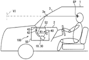
도 1은 제1 실시 형태에 있어서의 HUD 장치의 차량에의 탑재 상태를 도시하는 모식도이고,
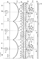
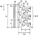
도 2는 제1 실시 형태에 있어서의 조명 유닛의 배열을 도시하는 모식도이고,
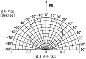
도 3은 제1 실시 형태에 있어서의 발광 소자의 방사 각도 분포를 나타내는 그래프이고,
도 4는 도 2의 조명 유닛의 하나의 구성을 간략화하여 도시하는 모식도이고,
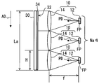
도 5는 도 2의 조명 유닛의 배열의 구성을 간략화하여 도시하는 모식도이고,
도 6은 도 5의 집광부를 제1 렌즈 소자와 제2 렌즈 소자로 분리하여 도시한 도면이고,
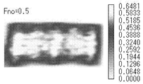
도 7은 제1 실시 형태에 있어서, 집광부의 F값이 0.5인 경우의 조명 대상면의 휘도를 나타내는 시뮬레이션 화상이고,
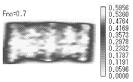
도 8은 제1 실시 형태에 있어서, 집광부의 F값이 0.7인 경우의 조명 대상면의 휘도를 나타내는 시뮬레이션 화상이고,
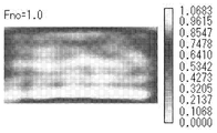
도 9는 제1 실시 형태에 있어서, 집광부의 F값이 1.0인 경우의 조명 대상면의 휘도를 나타내는 시뮬레이션 화상이고,
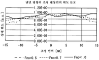
도 10은 배열 방향 단면에 있어서의 조명 대상면의 휘도 분포를 나타내는 그래프이고,
도 11은 제1 실시 형태에 있어서의 HUD 장치의 생산 방법을 나타내는 흐름도이고,
도 12는 제2 실시 형태에 있어서의 도 5에 대응하는 도면이고, 또한
도 13은 변형예 3에 있어서의 조명 유닛의 배열을 도시하는 모식도이다.The above and other objects, features and advantages of the present disclosure will become more apparent from the following detailed description with reference to the accompanying drawings. Fig.
1 is a schematic diagram showing a mounting state of the HUD device in a vehicle according to the first embodiment,
Fig. 2 is a schematic diagram showing the arrangement of the lighting units in the first embodiment,
Fig. 3 is a graph showing a radiation angle distribution of the light emitting element in the first embodiment,
Fig. 4 is a schematic diagram showing a simplified structure of one of the illumination units of Fig. 2,
FIG. 5 is a schematic view showing the arrangement of the arrangement of the illumination units of FIG. 2 in a simplified manner,
6 is a view showing the light collecting portion of FIG. 5 separated into a first lens element and a second lens element, and FIG.
7 is a simulation image showing luminance of the illumination target surface when the F value of the light collecting portion is 0.5 in the first embodiment,
8 is a simulation image showing the luminance of the illumination target surface when the F value of the light collecting portion is 0.7 in the first embodiment,
9 is a simulation image showing luminance of the illumination target surface when the F value of the light collecting portion is 1.0 in the first embodiment,
10 is a graph showing the luminance distribution of the illumination target surface in the arrangement direction cross section,
11 is a flowchart showing a production method of the HUD device in the first embodiment,
Fig. 12 is a view corresponding to Fig. 5 in the second embodiment, and Fig.
13 is a schematic diagram showing an arrangement of illumination units in
이하, 본 개시의 복수의 실시 형태를 도면에 기초하여 설명한다. 또한, 각 실시 형태에 있어서 대응하는 구성 요소에는 동일한 부호를 붙임으로써, 중복되는 설명을 생략하는 경우가 있다. 각 실시 형태에 있어서 구성의 일부분만을 설명하고 있는 경우, 당해 구성의 다른 부분에 대해서는, 선행하여 설명한 다른 실시 형태의 구성을 적용할 수 있다. 또한, 각 실시 형태의 설명에 있어서 명시하고 있는 구성의 조합뿐만 아니라, 특별히 조합에 지장이 발생하지 않으면, 명시하고 있지 않아도 복수의 실시 형태의 구성끼리를 부분적으로 조합할 수 있다.Best Mode for Carrying Out the Invention Hereinafter, a plurality of embodiments of the present disclosure will be described with reference to the drawings. In the embodiments, corresponding elements are denoted by the same reference numerals, and redundant explanations may be omitted. In the case where only a part of the configuration is described in each of the embodiments, the configuration of another embodiment described above can be applied to other portions of the configuration. In addition, not only the combination of the structures specified in the description of each embodiment but also the constitutions of a plurality of embodiments can be partially combined with each other even if the combination does not cause any trouble.
(제1 실시 형태)(First Embodiment)
도 1에 도시한 바와 같이, 본 개시의 제1 실시 형태에 의한 HUD 장치(100)는 이동체의 일종인 차량(1)에 탑재되며, 인스트루먼트 패널(2) 내에 수용되어 있다. HUD 장치(100)는 차량(1)의 투영 부재로서의 윈드실드(3)에 화상을 투영한다. 이에 의해, HUD 장치(100)는 화상을 차량(1)의 탑승자에 의해 시인 가능하게 허상 표시한다. 즉, 윈드실드(3)에 반사되는 화상의 광이, 차량(1)의 실내에 있어서 탑승자의 아이 포인트 EP에 도달하고, 탑승자가 당해 광을 지각한다. 그리고, 탑승자는, 허상 VI로서 표시되는 각종 정보를 인식할 수 있다. 허상 VI로서 표시되는 각종 정보로서는, 예를 들어 차속, 연료 잔량 등의 차량 상태값, 또는 도로 정보, 시계 보조 정보 등의 차량 정보를 들 수 있다.As shown in Fig. 1, the
차량(1)의 윈드실드(3)는 투광성의 유리 내지는 합성 수지 등에 의해 판 형상으로 형성되어 있다. 윈드실드(3)에 있어서, 실내측의 면은, 화상이 투영되는 투영면(3a)을 매끄러운 오목면 형상 또는 평면 형상으로 형성하고 있다. 또한, 투영 부재로서, 윈드실드(3) 대신에, 차량(1)과 별체로 되어 있는 컴바이너를 차량(1) 내에 설치하여, 당해 컴바이너에 화상을 투영하는 것이어도 된다.The
이와 같은 HUD 장치(100)의 구체적 구성을, 도 1∼도 6에 기초하여, 이하에 설명한다. HUD 장치(100)는 복수의 조명 유닛(10), 화상 형성부(30), 평면경(40) 및 오목경(42)을 구비하고 있고, 이들은 하우징(50)에 수용되어, 보유 지지되어 있다.The specific configuration of the
복수의 조명 유닛(10)은, 도 2에 도시한 바와 같이, 서로 배열되어 있다. 특히 본 실시 형태에서는, 1배열 방향 AD로 배열된 조명 유닛(10)이 3개 설치되어 있다. 각 조명 유닛(10)은, 각각 발광 소자(12) 및 집광부(14)를 갖고 있다.The plurality of
각 조명 유닛(10)에 있어서, 발광 소자(12)는 발열이 적은 발광 다이오드 소자이다. 발광 소자(12)는 광원용 회로 기판 상에 배치되며, 당해 기판 상의 배선 패턴을 통해, 전원과 전기적으로 접속되어 있다. 보다 상세하게, 발광 소자(12)는, 칩 형상의 청색 발광 다이오드 소자를, 투광성을 갖는 합성 수지에 황색 형광제를 혼합한 황색 형광체에 의해 밀봉함으로써 형성되어 있다. 청색 발광 다이오드 소자로부터 전류량에 따라서 발해지는 청색광에 의해, 황색 형광체가 여기되어 황색광을 발광하고, 청색광과 황색광의 합성에 의해 의사 백색의 조명광이 발해진다.In each
여기서 도 3에 도시한 바와 같이, 발광 소자(12)는 발광 강도가 최대로 되는 피크 방향 PD로부터 괴리됨에 따라서 발광 강도가 상대적으로 저하되는 방사 각도 분포로, 조명광을 발한다.Here, as shown in Fig. 3, the
각 조명 유닛(10)에 있어서 집광부(14)는, 도 2에 도시한 바와 같이, 발광 소자(12)와 쌍으로 되도록 설치되며, 발광 소자(12)와 마주보고 배치되어 있다. 구체적으로 제1 실시 형태의 집광부(14)는 2개의 렌즈 소자(15, 18)를 갖는 렌즈군으로 되어 있다.As shown in Fig. 2, the light-
제1 렌즈 소자(15)는 투광성의 합성 수지 내지는 유리 등으로 이루어지는 집광 소자이며, 집광부(14)에 있어서 발광 소자(12)측에 배치되어 있다. 제1 렌즈 소자(15)는, 발광 소자(12)측에 있어서, 입사측 굴절면(16)을 매끄러운 평면 형상으로 갖고 있다. 또한 제1 렌즈 소자(15)는, 제2 렌즈 소자(18)측에 있어서, 사출측 굴절면(17)을 매끄러운 볼록 곡면 형상으로 형성하고 있다.The
그리고, 조명 유닛(10)의 배열에 있어서 각 제1 렌즈 소자(15)는 1부품으로서 일체적으로 형성되어 렌즈 어레이를 구성하고 있다.In the arrangement of the
제2 렌즈 소자(18)는 투광성의 합성 수지 내지는 유리 등으로 이루어지는 집광 소자이며, 집광부(14)에 있어서 화상 형성부(30)측에 배치되어 있다. 제2 렌즈 소자(18)는, 제1 렌즈 소자(15)측에 있어서, 입사측 굴절면(16)을 매끄러운 평면 형상으로 형성하고 있다. 또한, 제2 렌즈 소자(18)는 화상 형성부(30)측에 있어서, 조명광을 굴절시키는 복합 광학면(20)을 형성하고 있다.The
복합 광학면(20)은 제2 렌즈 소자(18)의 전체면에 걸쳐 형성되어 있다. 복합 광학면(20)은 집광면(21)과, 편향면(22)이 교대로 이어지는 교호 배열 구조를 형성하고 있다.The composite
집광면(21)은, 집광 가상면 Sic를 배열 방향 AD로 소정의 분할 폭 Ws로 영역 분할한 1분할 영역으로서 형성되어 있다. 여기서, 집광 가상면 Sic는, 화상 형성부(30)측으로 볼록해지는 볼록면으로서 매끄러운 곡면 형상으로 되어 있다.The light-converging
편향면(22)은, 편향 가상면 Sid를 배열 방향 AD로 소정의 분할 폭 Ws로 영역 분할한 1분할 영역으로서 형성되어 있다. 편향 가상면 Sid는, 집광 가상면 Sic의 면 정점에 대응하는 개소에서 역구배로 바뀌는 복수의 경사면 Sis에 의해 구성되어 있고, 본 실시 형태에 있어서 각 경사면 Sis는, 매끄러운 평면 형상으로 되어 있다. 여기서, 각 경사면 Sis의 구배는, 집광 가상면 Sic의 대응하는 개소의 구배와는 역구배로 되도록 설정되어 있다.The deflecting
여기서, 집광면(21) 및 편향면(22)의 영역 분할에 있어서의 분할 폭 Ws는, 다양하게 설정되어 있지만, 각 면간에서 새그양이 대략 일정해지도록 설정됨으로써, 제2 렌즈 소자(18) 전체의 두께를 일정화하고 있다. 이들 집광면(21)과 편향면(22)이 교대로 배열됨으로써, 집광 가상면 Sic 중 일부의 형상, 및 편향 가상면 Sid 중 일부의 형상이 추출되어, 복합 광학면(20) 상에 재현되어 있다. 또한, 도 2에서는, 분할 폭 Ws 중 일부에만 그 치수가 도시되어 있다.Here, the division width Ws in the division of the light-collecting
이러한 집광면(21)은 조명광을 집광에 의해 평행화하고, 편향면(22)은 조명광을 집광면(21)에 의한 굴절과는 반대측으로 편향하도록 되어 있다.The condensing
각 집광면(21) 중, 집광 가상면 Sic의 면정점을 포함하는 집광면(21)에 있어서 면정점(21a)은, 발광 소자(12)와 제1 렌즈 소자(15)의 사출측 굴절면(17)의 면정점(17a)을 연결하는 직선 SL 상에 배치되어 있다. 이 직선 SL은 배열 방향 AD와 실질적으로 직교하고 있다. 이러한 제2 렌즈 소자(18)는 조명 유닛(10)의 배열에 있어서, 1부품으로서 일체적으로 형성되어 복합형 프레넬 렌즈 어레이를 구성하고 있다.The
그리고, 발광 소자(12)는 집광부(14)의 초점 FP 상에 배치되어 있다. 보다 상세하게는, 각 렌즈 소자(15, 18)의 합성 초점 거리(즉 주평면 PC로부터 초점까지의 거리, 도 6도 참조)인 집광부(14)의 초점 거리를 f라 하면, 발광 소자(12)의 배치에 있어서, 예를 들어 직선 SL을 따른 방향에 있어서 초점 거리 f의 10%, 배열 방향 AD에 있어서 초점 거리 f의 5%의 오차가 허용된다. 게다가 발광 소자(12)는 피크 방향 PD를 직선 SL을 따르게 하여 조명광을 발하도록 되어 있다.The light-emitting
이들 각 조명 유닛(10)에 있어서의 이러한 발광 소자(12)와 집광부(14)의 배치 구성 및 집광부(14)의 F값의 설정의 결과, 집광부(14)는 조명광 중 피크 방향 PD의 광을 포함하는 일부 방사속을 도입하여 집광에 의해 평행화하도록 되어 있다. 평행화된 광이 직선 SL을 따름으로써, 각 조명 유닛(10)에 있어서 직선 SL을 따른 광로가 구성되어 있다.As a result of the arrangement of the light-emitting
보다 상세하게, 발광 소자(12)의 발광 강도가 피크 방향 PD에 대하여, 제1 소정 비율(본 실시 형태에서는 50%) 이상인 분포 범위의 조명광을 일부 방사속으로서 집광 가능하게 하는 F값을 Fmin이라 한다. 또한, 발광 소자(12)의 발광 강도가 피크 방향 PD에 대하여 제1 소정 비율보다도 높은 제2 소정 비율(본 실시 형태에서는 90%) 이상인 분포 범위의 조명광을 일부 방사속으로서 집광 가능하게 하는 F값을 Fmax라 한다. 그렇게 하면, 집광부(14)의 F값은, Fmin 이상, 또한, Fmax 이하로 되어 있다. 또한, 본 실시 형태에 있어서의 F값의 정의에 대해서는 후술한다.More specifically, an F value that allows the illumination light of the
본 실시 형태의 방사 각도 분포의 발광 소자(12)에 대하여 말하면, Fmin의 경우, 도 3의 상대 발광 강도가 0.5로 되는 각도를 참조하면, 약 ±60도로 되어 있으므로, 집광부(14)는 조명광 중 -60도∼+60도의 범위를 일부 방사속으로서 도입하게 된다. Fmax의 경우, 도 3의 상대 발광 강도가 0.9로 되는 각도를 참조하면, 약 ±20도로 되어 있으므로, 집광부(14)는 조명광 중 -25도∼+25도의 범위를 일부 방사속으로서 도입하게 된다.With respect to the
이와 같이 조명을 행하는 1조명 유닛(10)은, 이와 같이 일부 방사속을 평행화하여, 화상 형성부(30)에 있어서 직선 SL과 실질적으로 직교하고 있는 조명 대상면(32) 중, 대응 개소를 조명한다.The illuminating
본 실시 형태의 화상 형성부(30)는, 도 1에 도시한 바와 같이, 박막 트랜지스터(Thin Film Transistor, TFT)를 사용한 액정 패널이며, 예를 들어 2차원 방향으로 배열된 복수의 액정 화소로 형성되는 액티브 매트릭스형의 액정 패널이다. 화상 형성부(30)에서는, 한 쌍의 편광판 및 한 쌍의 편광판 사이에 끼워진 액정층 등이 적층되어 있다. 편광판은, 전장 벡터가 소정 방향의 광을 투과시키고, 전장 벡터가 소정 방향과 실질적으로 수직인 방향의 광을 흡수하는 성질을 갖고, 한 쌍의 편광판은 당해 소정 방향을 실질적으로 직교하여 배치된다. 액정층은, 액정 화소마다의 전압 인가에 의해, 인가 전압에 따라서 액정층에 입사하는 광의 편광 방향을 회전시키는 것이 가능하게 되어 있다.As shown in Fig. 1, the
따라서, 화상 형성부(30)는 패널의 조명 유닛(10)측 표면인 조명 대상면(32)에의 광의 입사에 의해, 액정 화소마다의 당해 광의 투과율을 제어하여, 화상을 형성하는 것이 가능하게 되어 있다. 인접하는 액정 화소에는, 서로 상이한 색(예를 들어, 적, 녹 및 청)의 컬러 필터가 설치되어 있고, 이들의 조합에 의해, 다양한 색이 실현되도록 되어 있다.Therefore, the
여기서 각 조명 유닛(10)이 각각 조명 대상면(32) 중, 대응 개소를 조명함으로써, 조명 대상면(32)의 전체가 조명되도록 되어 있다. 본 실시 형태에서는, 1 배열 방향 AD로 3개의 조명 유닛(10)이 배열됨으로써, 배열 방향 AD에 대응하는 방향을 긴 쪽 방향으로 하는 직사각형의 화상이 형성된다.Here, each of the
또한 화상 형성부(30)는 조명 유닛(10)측 표면에 있어서, 확산부(34)를 갖고 있다. 확산부(34)는 조명 대상면(32)을 따라서 배치되며, 예를 들어 필름 형상으로 형성된다. 혹은 확산부(34)는 예를 들어 조명 대상면(32)에 미소한 요철을 마련함으로써 형성되어도 된다. 이러한 확산부(34)는 평행화된 조명광을 확산하고 나서 화상 형성부(30)를 투과시킨다.The
화상 형성부(30)에 의해 형성된 화상의 광은, 평면경(40)에 입사한다.The light of the image formed by the
평면경(40)은 합성 수지 내지는 유리 등으로 이루어지는 기재의 표면에, 반사면(41)으로서 알루미늄을 증착시키는 것 등에 의해 형성되어 있다. 반사면(41)은 매끄러운 평면 형상으로 형성되어 있다. 그리고, 평면경(40)은 화상 형성부(30)로부터의 화상의 광을, 오목경(42)을 향하여 반사한다.The
오목경(42)은 합성 수지 내지는 유리 등으로 이루어지는 기재의 표면에, 반사면(43)으로서 알루미늄을 증착시키는 것 등에 의해 형성되어 있다. 반사면(43)은 오목경(42)의 중심이 오목해지는 오목면으로서, 매끄러운 곡면 형상으로 형성되어 있다. 그리고, 오목경(42)은 평면경(40)으로부터의 화상의 광을, 윈드실드(3)를 향하여 반사한다.The
오목경(42)과 윈드실드(3) 사이에 있어서 하우징(50)에 개구부가 마련되어 있다. 개구부에는, 투광성의 방진 커버(52)가 설치되어 있다. 따라서, 오목경(42)으로부터의 화상의 광은, 당해 방진 커버(52)를 투과하여, 윈드실드(3)에 반사된다. 이렇게 하여 탑승자가 윈드실드(3)에 반사된 광을 허상 VI로서 시인 가능하게 되는 것이다.An opening is provided in the
다음에, 본 실시 형태의 조명 유닛(10)의 배열에 대하여, 도 4∼도 6에 간략화하여 도시된 배열 방향 AD의 단면 구성도를 사용하여 상세하게 설명한다.Next, the arrangement of the
먼저, 도 4를 기초로, 하나의 조명 유닛(10)이 조명 대상면(32)의 대응 개소를 조명하는 조명 폭 H에 대하여 생각한다. 지금, 발광 소자(12)가 초점 FP 상에 배치되어 있다. 따라서, 집광부(14)의 초점 거리 f를 사용하여, 집광부(14)의 F값인 Fno는 Fno=f/H로 정의될 수 있기 때문에, 평행화된 광에 의한 조명 폭 H는 H=f/Fno로 표현된다. 전술한 바와 같이, 집광부(14)의 F값은 Fmin 이상, 또한, Fmax 이하로 설정되어 있으므로, 결국, 조명 폭 H는,First, on the basis of FIG. 4, one
![]()
![]()
의 범위를 취할 수 있다.Lt; / RTI >
다음에, 도 5에 도시한 조명 유닛(10)의 배열에서, 배열 방향 AD에 있어서의 발광 소자(12)의 배열 개수를 Na라 하고, 배열 방향 AD에 대응하는 조명 대상면(32)의 치수를 La라 한다. 배열 방향 AD에 있어서 조명 대상면(32)의 전체 폭을 간극없이 조명하기 위해서는, Na=La/H의 배열 개수가 필요하다. 따라서, 본 실시 형태에서는, La/Na가Next, in the arrangement of the
![]()
![]()
의 범위로 설정되어 있다.As shown in FIG.
도 5에 대하여 집광부(14)를 제1 렌즈 소자(15) 및 제2 렌즈 소자(18)를 분리하여 도시한 도 6을 사용하여, 더욱 상세하게 설명한다. 여기서 발광 소자(12)와 제2 렌즈 소자(18) 사이의 거리를 Lop라 하고, 양쪽 렌즈 소자(15, 18) 사이의 거리를 d라 한다. 또한, 제1 렌즈 소자(15)의 초점 거리를 f1, 제2 렌즈 소자(18)의 초점 거리를 f2라 하면, 집광부(14)의 초점 거리 f는,5, the
![]()
![]()
를 만족시킨다..
이때 거리 Lop는 Lop=d+f·(1-d/f2)이다. 여기서, f2는 d에 대하여 크기 때문에, d/f2≒0으로 근사하면, 결국, Lop=d+f로 쓸 수 있다. 이것을 사용하여 식 2를 재기입하면, La/Na는,In this case, the distance Lop is Lop = d + f 占 (1-d / f2). Here, since f2 is larger than d, if d / f2 is approximated to 0, it can be written as Lop = d + f. When this is used to rewrite

의 범위로 설정되어 있는 것을 알 수 있다.Is set to a range of " a "
여기서, 식 2 혹은 식 4를 만족시키도록 설계된 HUD 장치(100)에 대하여, 발명자가 행한 허상 표시의 휘도 시뮬레이션에 대하여 설명한다. 각 조명 유닛(10)에 있어서, 집광부(14)의 F값을 Fno=0.5(도 7), Fno=0.7(도 8), Fno=1.0(도 9)으로 각각 설정한 경우가 도시되어 있다. 또한 배열 방향 AD 단면에 있어서의 휘도 분포가 도 10에 도시되어 있다.Here, the luminance simulation of the virtual image display performed by the inventor on the
이것을 검증하면, La/Na가 식 2의 하한에 가까워지는 Fno=1.0의 경우에서는, 이것보다도 F값이 작은 경우에 비해 휘도 불균일이 억제되어 있는 것을 알 수 있다. 한편 비교적 치수 La당의 배열 개수는 많아질 수 있다. 그리고, 식 2의 범위를 초과하여, F값을 Fmax보다도 크게 설정하면, F=1.0의 경우와 비교하여 휘도 불균일의 억제 효과가 그다지 변하지 않음에도 불구하고, 치수 La당의 배열 개수 Na가 급증해 버린다.As a result, it can be seen that, in the case of Fno = 1.0 where La / Na is close to the lower limit of
한편, La/Na가 식 2의 상한에 가까워지는 Fno=0.5의 경우에서는, 이것보다도 F값이 작은 경우에 비해, 치수 La당의 배열 개수 Na는 적어진다. 한편 비교적 휘도 불균일은 커진다. 그리고, 식 2의 범위를 초과하여, F값을 Fmin보다도 작게 설정하면, 휘도 불균일에 의해 허상 VI의 시인성에 큰 영향이 발생한다.On the other hand, in the case of Fno = 0.5 where La / Na is close to the upper limit of the
이하에서는, 이와 같은 HUD 장치(100)의 생산 방법에 대하여, 특히 조명 유닛(10)을 배열하는 방법을 중심으로, 도 11의 흐름도를 사용하여 설명한다.Hereinafter, a method of producing such a
먼저, 스텝 S10에서는, F값 설정 스텝으로서, 조명 유닛(10)의 배열에 있어서, 발광 소자(12)의 방사 각도 분포에 따른 집광부(14)의 F값을 설정한다. 특히 본 실시 형태에서는, 집광부(14)의 F값을 Fmin 이상, 또한, Fmax 이하로 설정한다. 스텝 S10의 종료 후, 스텝 S20으로 이행한다.First, in step S10, as the F value setting step, the F value of the light-collecting
스텝 S20에서는, 유닛수 설정 스텝으로서, F값에 기초하여, 조명 유닛(10)의 배열에 의해 조명 대상면(32)의 전체가 조명되도록, 조명 유닛(10)의 총수를 설정한다. 구체적으로는, F값 및 초점 거리 f로부터 조명 폭 H가 얻어지므로, 이것에 기초하여 La/H의 값을 잘라 올림으로써 얻어진 자연수를, 배열 개수 Na로서 설정하면 된다. 스텝 S20의 종료 후, 스텝 S30으로 이행한다.In step S20, as the unit number setting step, the total number of the
스텝 S30에서는, 조명 유닛(10)의 배열의 조립을 행한다. 즉, 각 조명 유닛(10)이 각각 조명 대상면(32) 중 대응 개소를 조명함으로써, 조명 대상면(32)의 전체가 조명되도록, 각 조명 유닛(10)을 서로 배열한다.In step S30, the arrangement of the
또한 그 밖의 요소가 전술한 바와 같이 구성됨으로써, HUD 장치(100)가 완성된다.Also, other elements are configured as described above, thereby completing the
(작용 효과)(Action effect)
이상 설명한 제1 실시 형태의 작용 효과를 이하에 설명한다.The operational effects of the first embodiment described above will be described below.
제1 실시 형태에 따르면, 각 조명 유닛(10)에 있어서, 발광 소자(12)로부터 발해지는 조명광은, 발광 소자(12)와 마주보고 배치된 집광부(14)에 의해 집광된다. 보다 상세하게는, 각 조명 유닛(10)에 있어서, 발광 강도가 최대로 되는 피크 방향 PD로부터 괴리됨에 따라서 발광 강도가 저하되는 방사 각도 분포의 조명광 중, 피크 방향 PD의 광을 포함하는 일부 방사속이, 집광부(14)의 집광에 의해 평행화된다. 요컨대, 조명광 중 피크 방향 PD에 대하여 발광 강도가 낮은 부분을 제외하고, 조명광을 평행화하는 것이 가능해진다. 이와 같은 집광부(14)에 의해 평행화된 조명광이 화상 형성부(30)의 조명 대상면(32) 중 대응 개소를 조명한다. 그리고, 서로 배열된 각 조명 유닛(10)에 의해, 조명 대상면(32)의 전체에의 균일화된 조명이 가능해지므로, 화상 전체의 휘도 불균일을 억제할 수 있다. 이상에 의해, 화상의 윈드실드(3)에의 투영에 의해 표시되는 허상 VI의 휘도 불균일을 저감 가능하게 되는 것이다.According to the first embodiment, in each
조명광 중 피크 방향 PD의 광을 포함하는 일부 방사속을 도입하는 집광부(14)에 있어서, F값이 과소한 경우, 조명광의 발광 강도가 보다 낮은 부분까지 집광되어 버려, 휘도 불균일의 저감 효과가 작아진다. 한편 F값이 과대한 경우, 조명 대상면(32)을 조명하기 위해 보다 다수의 조명 유닛(10)이 필요해진다. 따라서 제1 실시 형태에서는, 집광부(14)의 F값은 Fmin 이상, 또한, Fmax 이하로 되어 있다. 따라서, 조명 유닛(10)의 필요수와 휘도 불균일의 저감 효과의 조화가 도모되어, 효율적으로 허상 VI의 휘도 불균일을 저감하는 것이 가능해진다.In the
또한, 제1 실시 형태에 따르면, 식 2의 범위에 La/Na가 설정되어 있으므로, 1배열 방향 AD에 있어서, 발광 소자(12)의 배열 개수 Na의 증가를 억제하면서, 조명 대상면(32)에의 조명을 확실하게 균일화할 수 있다.According to the first embodiment, since La / Na is set in the range of
또한, 제1 실시 형태에 따르면, 조명광은, 집광부(14)가 갖는 렌즈 소자(18)의 복합 광학면(20)에서 굴절된다. 여기서, 복합 광학면(20)은 조명광을 집광에 의해 평행화하는 집광면(21)과, 편향면(22)이 교대로 이어지는 교호 배열 구조를, 형성하고 있다. 이 교호 배열 구조에서는, 발광 소자(12)로부터 대응하는 집광부(14)에 도입된 광은, 당해 집광면(21)에 의해 집광되는 한편, 대응하는 집광부(14)에 도입되지 않고 인접한 조명 유닛(10)에 입사한 광에 대해서도, 일부가 편향면(22)에 의해 다시 대응하는 조명 유닛(10)측으로 편광될 수 있다. 따라서, 인접한 조명 유닛(10)과 광이 서로 혼합될 뿐만 아니라, 도입되지 않은 광이 재이용되게 되므로, 허상 VI의 휘도 불균일을 저감할 수 있다.Further, according to the first embodiment, the illumination light is refracted on the composite
또한, 제1 실시 형태에 따르면, 식 4의 범위에 La/Na가 설정되어 있다. 이에 의해, 2개의 집광 소자로서 렌즈 소자(15, 18)를 갖는 집광부(14)에 있어서, 1배열 방향 AD에 있어서, 발광 소자(12)의 배열 개수 Na의 증가를 억제하면서, 조명 대상면(32)에의 조명을 확실하게 균일화할 수 있다.Further, according to the first embodiment, La / Na is set in the range of the expression (4). Thereby, in the
또한, 제1 실시 형태에 따르면, 화상 형성부(30)는 조명 대상면(32)을 따라서 배치되는 확산부(34)를 가지므로, 집광부(14)에 의해 조명광이 평행화되어도, 확산부(34)에 의해 화상의 광이 확산된다. 따라서, 효율적으로 허상 VI의 휘도 불균일을 저감하면서, 당해 허상 VI를 시인 가능한 시야각을 확대할 수 있다.According to the first embodiment, since the
또한, 제1 실시 형태의 HUD 장치(100)의 생산 방법에서는, 조명 유닛(10)에 있어서, 발광 소자(12)의 방사 각도 분포에 따라서 집광부(14)의 F값이 설정된다. 그리고, 설정된 F값에 기초하여, 조명 유닛(10)의 총수가 설정된다. 조명 유닛(10)의 총수의 설정에 의해, 당해 조명 유닛(10)의 배열에 의해 조명 대상면(32)의 전체가 조명된다. 이렇게 하여, 각 집광부(14)의 F값이 적합한 값으로 설정됨과 함께, 서로 배열된 각 조명 유닛(10)에 의해, 조명 대상면(32)의 전체에의 균일화된 조명이 가능해진다. 따라서, 조명 유닛(10)의 필요수와 화상 전체에 걸치는 휘도 불균일의 저감 효과의 조화를 도모할 수 있다. 이상에 의해, 화상의 윈드실드(3)에의 투영에 의해 표시되는 허상 VI의 휘도 불균일을 저감한 HUD 장치가 제공 가능해지는 것이다.In the manufacturing method of the
(제2 실시 형태)(Second Embodiment)
도 12에 도시한 바와 같이, 본 개시의 제2 실시 형태는 제1 실시 형태의 변형예이다. 제2 실시 형태에 대하여, 제1 실시 형태와는 상이한 점을 중심으로 설명한다.As shown in Fig. 12, the second embodiment of the present disclosure is a modification of the first embodiment. The second embodiment will be described mainly on the points different from the first embodiment.
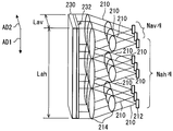
제2 실시 형태의 각 조명 유닛(210)은, 서로 교차하는 제1 배열 방향 AD1 및 제2 배열 방향 AD2의 2차원 방향으로 배열되어 있다. 특히 제2 실시 형태에서는, 제1 배열 방향 AD1은, 화상 형성부(230)의 조명 대상면(232)의 좌우 방향에 대응하고, 제2 배열 방향 AD2는, 조명 대상면(232)의 상하 방향에 대응하고 있다. 이렇게 하여, 제1 배열 방향 AD1과 제2 배열 방향 AD2가 실질적으로 직교하고 있다.Each of the
그리고, 조명 유닛(210)의 배열에서, 제1 배열 방향 AD1에 있어서의 발광 소자(212)의 배열 개수를 Nah라 하고, 조명 대상면(232)의 좌우 방향의 치수를 Lah라 하면, 제1 실시 형태의 식 2, 식 4와 마찬가지로, Lah/Nah는,In the arrangement of the
![]()
![]()

의 범위로 설정되어 있다.As shown in FIG.
또한, 조명 유닛(210)의 배열에서, 제2 배열 방향 AD2에 있어서의 발광 소자(212)의 배열 개수를 Nav라 하고, 조명 대상면(232)의 좌우 방향 치수를 Lav라 하면, 제1 실시 형태의 식 2, 식 4와 마찬가지로, Lav/Nav는,In the arrangement of the
![]()
![]()

의 범위로 설정되어 있다.As shown in FIG.
여기서, 각 배열 방향 AD1, AD2로 배열된 발광 소자(212)의 총수를 Ns라 하고, 조명 대상면(232)의 면적을 St라 한다. Ns=Nah·Nav, St=Lah·Lav이기 때문에, 식 5, 식 7로부터 St/Ns는,Here, the total number of the
![]()
![]()
의 범위로 설정되어 있는 것을 알 수 있다.Is set to a range of " a "
마찬가지로, 식 6, 식 8로부터 St/Ns는,Similarly, from Equation 6 and

의 범위로 설정되어 있는 것을 알 수 있다.Is set to a range of " a "
또한, 도 12에서는, 일부의 조명 유닛(210)에만 발광 소자(212) 및 집광부(214)의 부호가 붙여져 있다.In Fig. 12, only a part of the
또한, 생산 방법으로서는, 제1 실시 형태의 스텝 S20과 마찬가지의 배열 개수 Nah, Nav의 설정을, 각 배열 방향 AD1, AD2에 대하여 행함으로써, 조명 유닛의 총수를 설정할 수 있다.As the production method, the total number of illumination units can be set by setting the arrangement numbers Nah and Nav similar to those in step S20 of the first embodiment to the arrangement directions AD1 and AD2.
이와 같은 제2 실시 형태에 있어서도, 집광부(214)가 조명광 중 피크 방향 PD의 광을 포함하는 일부 방사속을 도입하여 집광에 의해 평행화하고 있으므로, 제1 실시 형태에 준한 작용 효과를 발휘하는 것이 가능해진다.In the second embodiment as described above, the
또한, 제2 실시 형태에 따르면, 2차원 방향으로 배열된 조명 유닛(210)의 배열에 있어서 식 9의 범위에 St/Ns가 설정되어 있으므로, 발광 소자(212)의 총수 Ns의 증가를 억제하면서, 조명 대상면(232)의 전체에의 조명을 확실하게 균일화할 수 있다.According to the second embodiment, since St / Ns is set in the range of expression 9 in the arrangement of the
또한, 제2 실시 형태에 따르면, 2차원 방향으로 배열된 조명 유닛(210)의 배열에 있어서 식 10의 범위에 St/Ns가 설정되어 있다. 이에 의해, 2개의 집광 소자를 갖는 집광부(214)에 있어서, 발광 소자(212)의 총수 Ns의 증가를 억제하면서, 조명 대상면(232)에의 조명을 확실하게 균일화할 수 있다.Further, according to the second embodiment, St / Ns is set in the range of
(다른 실시 형태)(Other Embodiments)
이상, 본 개시의 복수의 실시 형태에 대하여 설명하였지만, 본 개시는, 그것들의 실시 형태에 한정하여 해석되는 것은 아니고, 본 개시의 요지를 일탈하지 않는 범위 내에 있어서 다양한 실시 형태 및 조합에 적용할 수 있다.While the present invention has been described in connection with several embodiments, it is to be understood that the present invention is not limited to the specific embodiments thereof, but may be applied to various embodiments and combinations within the scope of the present disclosure. have.
구체적으로 변형예 1로서는, 제2 렌즈 소자(18)는 집광면(21)과 편향면(22)이 교대로 이어지는 교호 배열 구조를 형성한 복합 광학면(20)을 채용하고 있지 않아도 된다. 이 예로서, 제2 렌즈 소자(18)는 매끄러운 곡면 형상의 굴절면에 의해, 일부 방사속을 집광에 의해 평행화하는 것이어도 된다.Specifically, in the first modification, the
변형예 2로서는, 각 조명 유닛(10)에 있어서 집광부(14)는 1개의 렌즈 소자에 의해 구성되어 있어도 된다. 또한, 각 조명 유닛(10)에 있어서 집광부(14)는 3개 이상의 렌즈 소자에 의해 구성되어 있어도 된다.As a modified example 2, the
변형예 3으로서는, 각 조명 유닛(10)에 있어서 집광부(14)는 렌즈 소자 이외의 집광 소자를 채용할 수 있다. 도 13의 예에서는, 집광부(14)는 집광 소자로서 반사 소자를 포함하고 있다.As
변형예 4로서는, 화상 형성부(30)는 확산부(34)를 갖고 있지 않아도 된다.In
변형예 5로서는, 발광 소자(12)는 피크 방향 PD로부터 괴리됨에 따라서 발광 강도가 저하되는 방사 각도 분포이면 되고, 도 3에 도시한 분포보다도, 지향성이 높은 발광 소자 또는 지향성이 낮은 발광 소자를 채용할 수 있다.In the modified example 5, the
제2 실시 형태에 관한 변형예 6으로서는, 제1 배열 방향 AD1과 제2 배열 방향 AD2는 서로 교차하는 것이면, 직교하고 있지 않아도 된다.In Modification 6 relating to the second embodiment, the first arrangement direction AD1 and the second arrangement direction AD2 may be orthogonal if they intersect with each other.
변형예 7로서는, 차량(1) 이외의 선박 내지는 비행기 등의 각종 이동체(수송 기기)에, 본 개시를 적용해도 된다.As the modified example 7, this disclosure may be applied to various moving objects (transportation equipment) such as a ship or an airplane other than the
상술한 헤드업 디스플레이 장치는, 이동체(1)에 탑재되며, 화상을 투영 부재(3)에 투영함으로써, 화상을 탑승자에 의해 시인 가능하게 허상 표시한다. 상기 헤드업 디스플레이 장치는, 서로 배열되며, 조명을 행하는 복수의 조명 유닛(10, 210)을 구비한다. 상기 헤드업 디스플레이 장치는, 조명 대상면(32, 232)을 갖고, 각 조명 유닛이 각각 조명 대상면 중 대응 개소를 조명함으로써, 화상이 형성되는 화상 형성부(30, 230)를 더 구비한다. 각 조명 유닛은, 발광 강도가 최대로 되는 피크 방향 PD로부터 괴리됨에 따라서 발광 강도가 저하되는 방사 각도 분포로, 조명광을 발하는 발광 소자(12, 212)를 갖는다. 각 조명 유닛은, 발광 소자와 마주보고 배치되며, 조명광 중 피크 방향의 광을 포함하는 일부 방사속을 도입하여 집광에 의해 평행화하는 집광부(14, 214)를 더 갖는다.The above-described head-up display device is mounted on the moving
이와 같은 구성에 따르면, 각 조명 유닛에 있어서, 발광 소자로부터 발해지는 조명광은, 발광 소자와 마주보고 배치된 집광부에 의해 집광된다. 보다 상세하게는, 각 조명 유닛에 있어서, 발광 강도가 최대로 되는 피크 방향으로부터 괴리됨에 따라서 발광 강도가 저하되는 방사 각도 분포의 조명광 중, 피크 방향의 광을 포함하는 일부 방사속이, 집광부의 집광에 의해 평행화된다. 요컨대, 조명광 중 피크 방향에 대하여 발광 강도가 낮은 부분을 제외하고, 조명광을 평행화하는 것이 가능해진다. 이와 같은 집광부에 의해 평행화된 조명광이 화상 형성부의 조명 대상면 중 대응 개소를 조명한다. 그리고, 서로 배열된 각 조명 유닛에 의해, 조명 대상면의 전체에의 균일화된 조명이 가능해지므로, 화상 전체의 휘도 불균일을 억제할 수 있다. 이상에 의해, 화상의 투영 부재에의 투영에 의해 표시되는 허상의 휘도 불균일을 저감 가능하게 되는 것이다.According to such a configuration, in each illumination unit, the illumination light emitted from the light emitting element is condensed by the light collecting portion disposed facing the light emitting element. More specifically, in each illumination unit, among the illumination light of the radiation angle distribution in which the light emission intensity is lowered as it deviates from the peak direction in which the light emission intensity is maximized, some radiation spots including light in the peak direction, . In other words, the illumination light can be parallelized except the portion of the illumination light having a low light emission intensity with respect to the peak direction. The illumination light collimated by such a light condensing portion illuminates a corresponding portion of the illumination target surface of the image forming portion. Since uniform illumination is made possible over the entire illumination target surface by each of the illumination units arrayed, the brightness unevenness of the entire image can be suppressed. As described above, it is possible to reduce the luminance unevenness of the virtual image displayed by the projection of the image onto the projection member.
개시의 다른 하나에 따르면, 상기 헤드업 디스플레이 장치의 생산 방법은, 조명 유닛의 배열에 있어서, 발광 소자의 방사 각도 분포에 따라서 집광부의 F값을 설정하는 F값 설정 스텝 S10을 포함한다. 상기 생산 방법은, F값에 기초하여, 조명 유닛의 배열에 의해 조명 대상면의 전체가 조명되도록, 조명 유닛의 총수를 설정하는 유닛수 설정 스텝 S20을 더 포함한다.According to another aspect of the disclosure, the production method of the head-up display apparatus includes an F-number setting step S10 for setting the F value of the light-collecting section in accordance with the radiation angle distribution of the light-emitting element in the arrangement of the illumination units. The production method further includes a unit number setting step S20 for setting the total number of illumination units so that the entire illumination target surface is illuminated by the arrangement of the illumination units based on the F value.
조명광 중 피크 방향의 광을 포함하는 일부 방사속을 도입하는 집광부에 있어서, F값이 과소한 경우, 조명광의 발광 강도가 보다 낮은 부분까지 집광되어 버려, 휘도 불균일의 저감 효과가 작아진다. 한편 F값이 과대한 경우, 조명 대상면을 조명하기 위해 보다 다수의 조명 유닛이 필요해진다.In the light collecting part introducing a part of the radiation including the light in the peak direction of the illumination light, if the F value is too small, the light emission intensity of the illumination light is converged to the lower part, and the effect of reducing the luminance unevenness is reduced. On the other hand, when the F value is excessive, a larger number of illumination units are required to illuminate the illumination target surface.
따라서 본 개시의 생산 방법에서는, 조명 유닛에 있어서, 발광 소자의 방사 각도 분포에 따라서 집광부의 F값이 설정된다. 그리고, 설정된 F값에 기초하여, 조명 유닛의 총수가 설정된다. 조명 유닛의 총수의 설정에 의해, 당해 조명 유닛의 배열에 의해 조명 대상면의 전체가 조명된다. 이렇게 하여, 각 집광부의 F값이 적합한 값으로 설정됨과 함께, 서로 배열된 각 조명 유닛에 의해, 조명 대상면의 전체에의 균일화된 조명이 가능해진다. 따라서, 조명 유닛의 필요수와 화상 전체에 걸치는 휘도 불균일의 저감 효과의 조화를 도모할 수 있다. 이상에 의해, 화상의 투영 부재에의 투영에 의해 표시되는 허상의 휘도 불균일을 저감한 HUD 장치가 제공 가능해지는 것이다.Therefore, in the production method of the present disclosure, in the illumination unit, the F value of the light collecting portion is set in accordance with the radiation angle distribution of the light emitting element. Then, the total number of illumination units is set based on the set F value. By setting the total number of illumination units, the entire illumination target surface is illuminated by the arrangement of the illumination units. In this way, the F value of each light collecting portion is set to a suitable value, and uniform illumination of the entire illumination target surface becomes possible by each of the illumination units arranged to each other. Therefore, it is possible to balance the required number of illumination units and the reduction effect of luminance unevenness over the entire image. As described above, the HUD device capable of reducing the brightness unevenness of the virtual image displayed by the projection of the image onto the projection member can be provided.
본 개시는, 실시예에 준거하여 기술되었지만, 본 개시는 당해 실시예나 구조에 한정되는 것은 아니라고 이해된다. 본 개시는, 다양한 변형예나 균등 범위 내의 변형도 포함한다. 게다가, 다양한 조합이나 형태, 나아가, 그것들에 1요소만, 그것 이상, 혹은 그것 이하를 포함하는 다른 조합이나 형태도, 본 개시의 범주나 사상 범위에 들어가는 것이다.Although the present disclosure has been described in accordance with the embodiments, it is understood that the present disclosure is not limited to the embodiments and structures. This disclosure includes various modifications and variations within the scope of equivalents. Furthermore, various combinations or forms, and further combinations or forms thereof, including only one element, more or less, or less thereof, are within the scope or spirit of the present disclosure.
Claims (10)
서로 배열되며, 조명을 행하는 복수의 조명 유닛(10, 210)과,
조명 대상면(32, 232)을 갖고, 각 상기 조명 유닛이 각각 상기 조명 대상면 중 대응 개소를 조명함으로써, 상기 화상이 형성되는 화상 형성부(30, 230)를 구비하고,
각 상기 조명 유닛은,
발광 강도가 최대로 되는 피크 방향(PD)으로부터 괴리됨에 따라서 발광 강도가 저하되는 방사 각도 분포로, 조명광을 발하는 발광 소자(12, 212)와,
상기 발광 소자와 마주보고 배치되며, 상기 조명광 중 상기 피크 방향의 광을 포함하는 일부 방사속을 도입하여 집광에 의해 평행화하는 집광부(14, 214)를 갖는, 헤드업 디스플레이 장치.A head-up display device mounted on a moving body (1) for projecting an image onto a projection member (3) and visually displaying the image by a passenger visually,
A plurality of illumination units (10, 210) arranged to one another and performing illumination,
(30, 230) having the illumination target surfaces (32, 232) and each of the illumination units illuminating a corresponding one of the illumination target surfaces to form the image,
Each of said lighting units comprising:
The light emitting elements 12 and 212 that emit the illumination light with a radiation angle distribution in which the light emission intensity is lowered as the emission intensity deviates from the peak direction PD in which the light emission intensity is maximized,
And a light collecting part (14, 214) arranged to face the light emitting element and to introduce a part of the illumination light including the light in the peak direction of the illumination light and collimate it by condensing.
상기 발광 소자의 발광 강도가 상기 피크 방향에 대하여 50% 이상인 분포 범위의 상기 조명광을 상기 일부 방사속으로서 집광 가능하게 하는 F값을 Fmin이라 하고, 상기 발광 소자의 발광 강도가 상기 피크 방향에 대하여 90% 이상인 분포 범위의 상기 조명광을 상기 일부 방사속으로서 집광 가능하게 하는 F값을 Fmax라 하면,
각 상기 조명 유닛에 있어서, 각 상기 집광부의 F값은 Fmin 이상, 또한, Fmax 이하인, 헤드업 디스플레이 장치.The method according to claim 1,
An F value that allows the illumination light of the light emitting element to be condensed as a part of the radiation within a distribution range of 50% or more with respect to the peak direction is Fmin, and the light emission intensity of the light emitting element is 90 % Of the illumination light is allowed to be condensed as the part of the radiation,
In each of the illumination units, the F value of each of the light collecting units is Fmin or more and Fmax or less.
상기 조명 유닛의 배열에서, 1배열 방향(AD)에 있어서의 상기 발광 소자의 배열 개수를 Na라 하고, 상기 1배열 방향에 대응하는 상기 조명 대상면의 치수를 La라 하고, 각 상기 집광부의 초점 거리를 f라 하면, La/Na는,
f/Fmax≤Lt/Na≤f/Fmin
의 범위로 설정되어 있는, 헤드업 디스플레이 장치.3. The method of claim 2,
In the arrangement of the illumination units, Na is the number of the light emitting elements in one arrangement direction (AD), La is the dimension of the illumination target surface corresponding to the one arrangement direction, When the focal length is f, La /
f / Fmax? Lt / Na? f / Fmin
Of the head-up display device.
각 조명 유닛은, 서로 교차하는 제1 배열 방향(AD1) 및 제2 배열 방향(AD2)의 2차원 방향으로 배열되고,
상기 조명 유닛의 배열에서, 상기 발광 소자의 총수를 Ns라 하고, 상기 조명 대상면의 면적을 St라 하고, 각 상기 집광부의 초점 거리를 f라 하면, St/Ns는,
f2/Fmax2≤St/Ns≤f2/Fmin2
의 범위로 설정되어 있는, 헤드업 디스플레이 장치.The method according to claim 2 or 3,
Each of the illumination units is arranged in a two-dimensional direction of a first arrangement direction AD1 and a second arrangement direction AD2 intersecting with each other,
In the arrangement of the illumination units, when the total number of the light emitting elements is Ns, the area of the illumination target surface is St, and the focal distance of each of the light condensing portions is f, St /
f 2 / Fmax 2 ≤St / Ns≤f 2 / Fmin 2
Of the head-up display device.
각 상기 조명 유닛에 있어서, 상기 집광부는, 상기 조명광을 복합 광학면(20)에서 굴절시키는 렌즈 소자(18)를 갖고,
상기 복합 광학면은, 상기 조명광을 집광에 의해 평행화하는 집광면(21)과, 상기 조명광을 상기 집광면의 집광에 의한 굴절과는 반대측으로 편향하는 편향면(22)이, 교대로 이어지는 교호 배열 구조를 형성하고 있는, 헤드업 디스플레이 장치.5. The method according to any one of claims 1 to 4,
In each of the illumination units, the condensing unit has a lens element (18) for refracting the illumination light on the composite optical surface (20)
The composite optical surface includes a condensing surface (21) for collimating the illumination light by condensing, and a deflecting surface (22) for deflecting the illumination light to the opposite side of refraction caused by condensing the condensing surface, Forming an array structure.
각 상기 조명 유닛에서, 상기 집광부는, 상기 발광 소자와 상기 대응 개소 사이의 광로 상에 2개의 집광 소자(15, 18)를 갖고,
상기 조명 유닛의 배열에서, 1배열 방향에 있어서의 상기 발광 소자의 배열 개수를 Na라 하고, 상기 1배열 방향에 대응하는 상기 조명 대상면의 치수를 La라 하고, 상기 발광 소자와 각 상기 집광 소자 중 상기 대응 개소측의 집광 소자 사이의 거리를 Lop라 하고, 각 상기 집광 소자간의 거리를 d라 하면, La/Na는,
(Lop-d)/Fmax≤La/Na≤(Lop-d)/Fmin
의 범위로 설정되어 있는, 헤드업 디스플레이 장치.3. The method of claim 2,
In each of the illumination units, the condensing unit has two light converging elements (15, 18) on an optical path between the light emitting element and the corresponding portion,
In the arrangement of the illumination units, the number of the light emitting elements arranged in one arrangement direction is Na, the dimension of the illumination target surface corresponding to the one arrangement direction is La, The distance between the light-converging elements on the side of the corresponding portion is denoted by Lop, and the distance between the light-converging elements is denoted by d, La /
(Lop-d) / Fmax? La / Na? (Lop-d) / Fmin
Of the head-up display device.
각 상기 조명 유닛은, 서로 교차하는 제1 배열 방향 및 제2 배열 방향으로 2차원 방향으로 배열되고,
각 상기 조명 유닛에 있어서, 상기 집광부는, 상기 발광 소자와 상기 대응 개소 사이의 광로 상에 2개의 집광 소자를 갖고,
상기 조명 유닛의 배열에서, 상기 발광 소자의 총수를 Ns라 하고, 상기 조명 대상면의 면적을 St라 하고, 상기 발광 소자와 각 상기 집광 소자 중 상기 대응 개소측의 집광 소자 사이의 거리를 Lop라 하고, 각 상기 집광 소자간의 거리를 d라 하면, St/Ns는,
(Lop-d)2/Fmax2≤St/Ns≤(Lop-d)2/Fmin2
의 범위로 설정되어 있는, 헤드업 디스플레이 장치.7. The method according to claim 2 or 6,
Each of said illumination units is arranged in a two-dimensional direction in a first arrangement direction and a second arrangement direction intersecting with each other,
In each of the illumination units, the condensing unit has two light converging elements on an optical path between the light emitting element and the corresponding portion,
In the arrangement of the illumination units, the total number of the light emitting elements is Ns, the area of the illumination target surface is St, and the distance between the light emitting elements and the light collecting elements on the corresponding spot side among the light collecting elements is Lop And the distance between each of the light converging elements is denoted by d, St /
(Lop-d) 2 / Fmax 2? St / Ns? (Lop-d) 2 / Fmin 2
Of the head-up display device.
상기 발광 소자 중 적어도 하나는, 상기 조명광을 복합 광학면에서 굴절시키는 렌즈 소자이며,
상기 복합 광학면은, 상기 조명광을 집광에 의해 평행화하는 집광면과, 상기 조명광을 상기 집광면의 집광에 의한 굴절과는 반대측으로 편향하는 편향면이, 교대로 이어지는 교호 배열 구조를 형성하고 있는, 헤드업 디스플레이 장치.8. The method according to claim 6 or 7,
At least one of the light emitting elements is a lens element for refracting the illumination light on the composite optical surface,
The composite optical surface forms an alternate arrangement structure in which the light converging surface for parallel collimating the illumination light and the deflecting surface for deflecting the illumination light to the opposite side of the refraction caused by the condensing of the condensing surface , Head-up display device.
상기 화상 형성부는, 상기 조명 대상면을 따라서 배치되며, 상기 집광부에 의해 평행화된 상기 조명광을 확산하는 확산부(34)를 갖는, 헤드업 디스플레이 장치.9. The method according to any one of claims 1 to 8,
Wherein the image forming section has a diffusion section (34) arranged along the illumination target surface and diffusing the illumination light parallelized by the condensing section.
서로 배열되며, 조명을 행하는 복수의 조명 유닛(10, 210)과,
조명 대상면(32, 232)을 갖고, 각 상기 조명 유닛이 각각 상기 조명 대상면 중 대응 개소를 조명함으로써, 상기 화상이 형성되는 화상 형성부(30, 230)를 구비하고,
각 상기 조명 유닛은,
발광 강도가 최대로 되는 피크 방향(PD)으로부터 괴리됨에 따라서 발광 강도가 저하되는 방사 각도 분포로, 조명광을 발하는 발광 소자(12, 212)와,
상기 발광 소자와 마주보고 배치되며, 상기 조명광 중 상기 피크 방향의 광을 포함하는 일부분을 도입하여 집광에 의해 평행화하는 집광부(14, 214)를 갖는 헤드업 디스플레이 장치의 생산 방법이며,
상기 조명 유닛의 배열에 있어서, 상기 발광 소자의 상기 방사 각도 분포에 따라서 상기 집광부의 F값을 설정하는 F값 설정 스텝(S10)과,
상기 F값에 기초하여, 상기 조명 유닛의 배열에 의해 상기 조명 대상면의 전체가 조명되도록, 상기 조명 유닛의 총수를 설정하는 유닛수 설정 스텝(S20)을 포함하는, 헤드업 디스플레이 장치의 생산 방법.A head-up display device mounted on a moving body (1) for projecting an image onto a projection member (3) and visually displaying the image visually by a passenger,
A plurality of illumination units (10, 210) arranged to one another and performing illumination,
(30, 230) having the illumination target surfaces (32, 232) and each of the illumination units illuminating a corresponding one of the illumination target surfaces to form the image,
Each of said lighting units comprising:
The light emitting elements 12 and 212 that emit the illumination light with a radiation angle distribution in which the light emission intensity is lowered as the emission intensity deviates from the peak direction PD in which the light emission intensity is maximized,
And a light collecting part (14, 214) disposed opposite to the light emitting element and introducing a part including the light in the peak direction of the illumination light and collimating the light by condensing,
An F-number setting step (S10) of setting the F-number of the light-collecting section in accordance with the radiation angle distribution of the light-emitting element,
And a unit number setting step (S20) for setting the total number of the illumination units so that the entire illumination target surface is illuminated by the arrangement of the illumination units based on the F value. .
Applications Claiming Priority (3)
| Application Number | Priority Date | Filing Date | Title |
|---|---|---|---|
| JPJP-P-2016-012761 | 2016-01-26 | ||
| JP2016012761A JP2017134175A (en) | 2016-01-26 | 2016-01-26 | Head-up display device and method for producing the same |
| PCT/JP2016/081199 WO2017130481A1 (en) | 2016-01-26 | 2016-10-21 | Head up display apparatus and manufacturing method of same |
Publications (1)
| Publication Number | Publication Date |
|---|---|
| KR20180086225A true KR20180086225A (en) | 2018-07-30 |
Family
ID=59397806
Family Applications (1)
| Application Number | Title | Priority Date | Filing Date |
|---|---|---|---|
| KR1020187017644A KR20180086225A (en) | 2016-01-26 | 2016-10-21 | Head-up display device and production method thereof |
Country Status (6)
| Country | Link |
|---|---|
| US (1) | US20190025581A1 (en) |
| JP (1) | JP2017134175A (en) |
| KR (1) | KR20180086225A (en) |
| CN (1) | CN108474948A (en) |
| DE (1) | DE112016006305T5 (en) |
| WO (1) | WO2017130481A1 (en) |
Cited By (1)
| Publication number | Priority date | Publication date | Assignee | Title |
|---|---|---|---|---|
| US11360301B2 (en) | 2019-12-12 | 2022-06-14 | Samsung Electronics Co., Ltd. | Augmented reality head-up display apparatus |
Families Citing this family (2)
| Publication number | Priority date | Publication date | Assignee | Title |
|---|---|---|---|---|
| WO2019087594A1 (en) * | 2017-10-30 | 2019-05-09 | ソニー株式会社 | Display apparatus and display method |
| CN212160232U (en) * | 2019-05-17 | 2020-12-15 | 未来(北京)黑科技有限公司 | Head-up display system |
Citations (1)
| Publication number | Priority date | Publication date | Assignee | Title |
|---|---|---|---|---|
| JP2007108429A (en) | 2005-10-13 | 2007-04-26 | Denso Corp | Display device and headup display device for vehicle equipped therewith |
Family Cites Families (14)
| Publication number | Priority date | Publication date | Assignee | Title |
|---|---|---|---|---|
| US5612821A (en) * | 1995-06-15 | 1997-03-18 | United Technologies Corporation | Micro lens system for controlling an optical beam pattern |
| JP2003104087A (en) * | 2001-09-28 | 2003-04-09 | Nippon Seiki Co Ltd | Displaying device |
| JP4671117B2 (en) * | 2005-09-22 | 2011-04-13 | ミネベア株式会社 | Illumination device and light source unit using the same |
| JP2008209665A (en) * | 2007-02-27 | 2008-09-11 | Nippon Seiki Co Ltd | Head-up display device |
| JP2008268680A (en) * | 2007-04-24 | 2008-11-06 | Nippon Seiki Co Ltd | Display device |
| JP4952762B2 (en) * | 2009-09-30 | 2012-06-13 | 株式会社デンソー | Lighting device |
| WO2012002029A1 (en) * | 2010-07-01 | 2012-01-05 | シャープ株式会社 | Illumination device, display device, television receiving device, and led light source |
| JP5674032B2 (en) * | 2011-03-25 | 2015-02-18 | 日本精機株式会社 | Head-up display device |
| JP6237249B2 (en) * | 2014-01-15 | 2017-11-29 | 株式会社デンソー | Illumination lens, illumination unit, and head-up display device |
| JP2015219425A (en) * | 2014-05-20 | 2015-12-07 | 三菱電機株式会社 | Luminaire and head-up display system |
| JP6501052B2 (en) * | 2014-05-30 | 2019-04-17 | 日亜化学工業株式会社 | Light module, lighting device and display device |
| JP6287605B2 (en) * | 2014-06-09 | 2018-03-07 | 株式会社デンソー | Head-up display device and lighting unit thereof |
| JP6369148B2 (en) * | 2014-06-09 | 2018-08-08 | 株式会社デンソー | Head-up display device and lighting unit thereof |
| JP2016012761A (en) | 2014-06-27 | 2016-01-21 | セイコーエプソン株式会社 | Reading system, reading control device, and method for controlling reading control device |
-
2016
- 2016-01-26 JP JP2016012761A patent/JP2017134175A/en active Pending
- 2016-10-21 US US16/071,918 patent/US20190025581A1/en not_active Abandoned
- 2016-10-21 DE DE112016006305.9T patent/DE112016006305T5/en not_active Withdrawn
- 2016-10-21 KR KR1020187017644A patent/KR20180086225A/en not_active Application Discontinuation
- 2016-10-21 CN CN201680075745.1A patent/CN108474948A/en active Pending
- 2016-10-21 WO PCT/JP2016/081199 patent/WO2017130481A1/en active Application Filing
Patent Citations (1)
| Publication number | Priority date | Publication date | Assignee | Title |
|---|---|---|---|---|
| JP2007108429A (en) | 2005-10-13 | 2007-04-26 | Denso Corp | Display device and headup display device for vehicle equipped therewith |
Cited By (1)
| Publication number | Priority date | Publication date | Assignee | Title |
|---|---|---|---|---|
| US11360301B2 (en) | 2019-12-12 | 2022-06-14 | Samsung Electronics Co., Ltd. | Augmented reality head-up display apparatus |
Also Published As
| Publication number | Publication date |
|---|---|
| CN108474948A (en) | 2018-08-31 |
| JP2017134175A (en) | 2017-08-03 |
| DE112016006305T5 (en) | 2018-10-18 |
| WO2017130481A1 (en) | 2017-08-03 |
| US20190025581A1 (en) | 2019-01-24 |
Similar Documents
| Publication | Publication Date | Title |
|---|---|---|
| JP6579126B2 (en) | Head-up display device and image projection unit | |
| JP6579212B2 (en) | Head-up display device | |
| JP6508125B2 (en) | HEAD-UP DISPLAY DEVICE AND IMAGE PROJECTION UNIT | |
| JP6677268B2 (en) | Head-up display device | |
| KR101940946B1 (en) | Head-up display device | |
| JP7172840B2 (en) | virtual image display | |
| US10793003B2 (en) | Head-up display device | |
| KR20180086225A (en) | Head-up display device and production method thereof | |
| WO2017145557A1 (en) | Head-up display device | |
| JP6984619B2 (en) | Virtual image display device | |
| WO2017145558A1 (en) | Head-up display device | |
| WO2021182097A1 (en) | Virtual image display device | |
| WO2017203871A1 (en) | Head-up display device and image projection unit | |
| JP2022011390A (en) | Virtual image display device |
Legal Events
| Date | Code | Title | Description |
|---|---|---|---|
| A201 | Request for examination | ||
| E902 | Notification of reason for refusal | ||
| E601 | Decision to refuse application |