KR20180071063A - Water catchment type water permeable block - Google Patents
Water catchment type water permeable block Download PDFInfo
- Publication number
- KR20180071063A KR20180071063A KR1020160173818A KR20160173818A KR20180071063A KR 20180071063 A KR20180071063 A KR 20180071063A KR 1020160173818 A KR1020160173818 A KR 1020160173818A KR 20160173818 A KR20160173818 A KR 20160173818A KR 20180071063 A KR20180071063 A KR 20180071063A
- Authority
- KR
- South Korea
- Prior art keywords
- block
- permeable
- water
- block body
- collecting
- Prior art date
Links
Images


Classifications
-
- E—FIXED CONSTRUCTIONS
- E01—CONSTRUCTION OF ROADS, RAILWAYS, OR BRIDGES
- E01C—CONSTRUCTION OF, OR SURFACES FOR, ROADS, SPORTS GROUNDS, OR THE LIKE; MACHINES OR AUXILIARY TOOLS FOR CONSTRUCTION OR REPAIR
- E01C11/00—Details of pavings
- E01C11/22—Gutters; Kerbs ; Surface drainage of streets, roads or like traffic areas
- E01C11/224—Surface drainage of streets
- E01C11/225—Paving specially adapted for through-the-surfacing drainage, e.g. perforated, porous; Preformed paving elements comprising, or adapted to form, passageways for carrying off drainage
-
- E—FIXED CONSTRUCTIONS
- E03—WATER SUPPLY; SEWERAGE
- E03F—SEWERS; CESSPOOLS
- E03F1/00—Methods, systems, or installations for draining-off sewage or storm water
- E03F1/002—Methods, systems, or installations for draining-off sewage or storm water with disposal into the ground, e.g. via dry wells
-
- E—FIXED CONSTRUCTIONS
- E03—WATER SUPPLY; SEWERAGE
- E03F—SEWERS; CESSPOOLS
- E03F5/00—Sewerage structures
- E03F5/10—Collecting-tanks; Equalising-tanks for regulating the run-off; Laying-up basins
- E03F5/101—Dedicated additional structures, interposed or parallel to the sewer system
-
- Y—GENERAL TAGGING OF NEW TECHNOLOGICAL DEVELOPMENTS; GENERAL TAGGING OF CROSS-SECTIONAL TECHNOLOGIES SPANNING OVER SEVERAL SECTIONS OF THE IPC; TECHNICAL SUBJECTS COVERED BY FORMER USPC CROSS-REFERENCE ART COLLECTIONS [XRACs] AND DIGESTS
- Y02—TECHNOLOGIES OR APPLICATIONS FOR MITIGATION OR ADAPTATION AGAINST CLIMATE CHANGE
- Y02A—TECHNOLOGIES FOR ADAPTATION TO CLIMATE CHANGE
- Y02A30/00—Adapting or protecting infrastructure or their operation
- Y02A30/60—Planning or developing urban green infrastructure
Abstract
Description
본 발명은 집수식 투수블록에 관한 것으로, 상세하게는 집수관을 이용하여 다량의 우수를 저류하고 신속하게 지반 내로 투수시킬 수 있으며, 투수 성능이 지속적으로 발휘될 수 있도록 안정적인 유지관리가 가능한 집수식 투수블록에 관한 것이다.The present invention relates to a water-collecting permeable block, and more particularly, to a water-collecting permeable block capable of storing a large amount of stormwater using a collecting water pipe and allowing quick penetration into the ground, Permeable block.
일반적으로 보도블록은 단순히 시멘트와 모래를 일정 비율로 혼합 성형한 것으로, 이러한 보도블록은 보행자의 지면 보행을 돕고자 지면 층에 일정의 두께로 모래를 깔고 그 위에 연이어 맞결합 시공하여 사용하고 있다.Generally, the sidewalk block is formed by simply mixing cement and sand at a certain ratio. These sidewalk blocks are used by laying sand on the ground layer to sand the floor layer to help pedestrians to walk on the ground.
이러한 시멘트 보도블록은 단순히 지표면의 외장처리를 목적으로 할 뿐, 지표와 대기를 단절시킴으로 인한 물의 순환구조를 파괴시켜서 많은 환경문제들의 원인이 되고, 우수의 배수가 어렵게 되어 우수가 오랫동안 머무르게 되는 원인이 되고 있다.Such cement press block is merely intended to treat the surface of the earth's surface, and it breaks the circulation structure of the water by cutting off the surface and the atmosphere, which causes many environmental problems. It is difficult to drain the water and causes the rainwater to stay for a long time .
이와 같은 종래의 보도블록의 문제점을 극복하고자, 블록 자체에 임의 크기로 투수구멍을 형성시키거나 자체 내부 공극을 크게 하여 투수성을 향상시킨 투수블록이 제안되었다. 한국등록실용신안공보 제20-0451992호에 개시된 투수 패드를 구비한 보도블럭용 포석 케이스가 대표적인 일례이다.In order to overcome the problems of the conventional press block, a permeable block having a permeability improved by forming a permeable hole at an arbitrary size in the block itself or by enlarging its inner cavity has been proposed. A typical example is a pavement case for a sidewalk block having a pitcher pad disclosed in Korean Registered Utility Model No. 20-0451992.
그러나 이와 같은 종래 투수블록은 투수되는 우수의 양도 적을 뿐 아니라, 유지보수가 용이하지 못해 시간이 경과할수록 투수능력이 현격히 떨어져 결국 투수블록으로서 제기능을 발휘하지 못하는 단점이 있으며, 그렇다고 투수량을 늘리기 위해 투수 구멍을 키우는 경우 우수에 섞인 오염물질이 투수기층을 오염시켜 더 큰 문제가 야기될 수 있다. However, such a conventional permeable block has a disadvantage in that the permeability of the permeable water is not only low, but also the maintenance is not easy and the permeability is remarkably deteriorated over time, and as a result, the permeable block does not function as a permeable block. Raising permeability holes can contaminate the permeable layer with contaminants mixed with rainwater, which can lead to greater problems.
본 발명이 해결하고자 하는 과제는, 집수관을 이용하여 다량의 우수를 저류하고 신속하게 지반 내로 투수시킬 수 있고, 내부에 오염물질이 쌓이더라도 이를 용이하게 제거할 수 있어 안정적인 투수 성능이 지속적으로 발휘될 수 있는 집수식 투수블록을 제공하고자 하는 것이다.A problem to be solved by the present invention is that a large amount of stormwater can be stored using a water collecting pipe and can be rapidly permeated into the ground, and even if contaminants are piled in the inside, it can be easily removed, To provide a collection of numerical pitcher blocks that can be used.
과제 해결을 위한 수단으로서 본 발명의 실시 예에 따르면, According to an embodiment of the present invention as a means for solving the problem,
보도 또는 차도의 노면 자재로 사용되고 우천 시 빗물을 신속하게 지반 내로 투수시킬 수 있도록 한 것으로서,It is used as the road surface material of a sidewalk or a roadway, and it is possible to quickly transmit rainwater into the ground during rainy weather.
중앙에 집수부가 형성되고, 측면에 일정한 간격으로 측면 투수홀이 형성된 박스모양의 개방형 블록 본체;A box-shaped open block body having a water collecting part formed at the center thereof and formed with side penetrating holes at regular intervals on its side;
상기 블록 본체 상부에 설치되며, 우수가 상기 블록 본체 내부로 유입될 수 있도록 다수의 구멍이 형성된 투수판;A plurality of holes formed in the block body to allow the storm to flow into the block body;
상기 블록 본체의 집수부 하단에 연결되고, 모래로 이루어진 투수표층과 자갈들로 이루어진 투수기층에 매립되며, 상기 투수기층에 매립된 부분의 측면부에 다수의 투수구멍을 갖는 상부가 개구된 통형 구조의 집수관;A tubular structure having an upper portion which is connected to a lower end of a collecting portion of the block body and is buried in a permeable layer made of sand and a gravel and which has a plurality of permeable holes at a side portion of the portion buried in the permeable layer House water pipes;
상기 집수관 내부에 설치되며, 상기 투수구멍을 통해 투수기층으로 배출되는 우수에 포함된 오염물질을 걸러내는 포집망; 및A trapping mesh installed in the water collecting pipe to filter contaminants contained in the rainwater discharged to the water permeable layer through the watertight hole; And
상기 블록 본체 둘레에 연접 설치되며, 내측에 제1 방향 유로와, 제1 방향 유로와 교차하며 상기 측면 투수홀과 연통되는 제2 방향 유로가 형성된 복수의 우수유도블록;을 포함하는 집수식 투수블록을 제공한다. And a plurality of storm valve blocks provided adjacent to the block body and having a first directional flow path and a second directional flow path intersecting the first directional flow path and communicating with the side clearance holes, .
여기서 상기 블록 본체는, Here,
블록 본체 중앙에 형성되며, 상부와 하부가 개방된 중공의 집수부; A hollow collecting part formed at the center of the block body and having upper and lower openings;
상기 집수부를 둘러싸도록 구성되며, 상부가 개방되고 하부에 투수구멍이 형성되며, 측면에 상기 측면 투수홀이 형성된 유도부; 및A guiding part which is configured to surround the collecting part, the upper part of which is open, the lower part of which has a water hole, and the side surface of which is formed a side hole; And
상기 유도부 내부에 상기 집수부를 향하여 하향 경사지게 설치되는 경사판;으로 구성될 수 있다.And a swash plate disposed inside the guide portion so as to be inclined downward toward the collecting portion.
또한, 상기 유도부는 격벽에 의해 복수의 우수유도 셀로 구획될 수 있다.In addition, the guide portion may be partitioned into a plurality of excellent guiding cells by barrier ribs.
그리고 상기 집수부 위치에 대응되는 투수판의 일부가 상기 집수부 직경에 대응되는 크기로 개구되고, 개구된 부분에 다수의 구멍이 형성된 유지보수덮개가 분리 가능하게 설치될 수 있다.A portion of the permeable plate corresponding to the position of the collecting part is opened to a size corresponding to the diameter of the collecting part, and a maintenance lid having a plurality of holes formed in the opened part is detachably installed.
또한, 상기 집수관의 저부 둘레에 접지날개가 형성되고, 상기 접지날개에는 상기 투수기층 하부의 지층 표면에 상기 집수관을 고정시킬 수 있도록 앙카홀이 형성될 수 있다.Further, a ground blade may be formed around the bottom of the collector pipe, and an anchor hole may be formed in the ground blade so as to fix the collector pipe to the surface of the ground layer below the permeable layer.
또한, 상기 포집망은 상부가 개구된 용기 형태로 구성되며, 상기 투수기층에 대응되는 높이로 형성될 수 있으며, 상기 집수관으로부터 분리될 수 있다.In addition, the collecting net may be formed in the form of a container having an open upper portion, and may be formed at a height corresponding to the water permeable layer, and may be separated from the collecting pipe.
또한, 상기 우수유도블록은 블록 본체 상부에 투수판이 결합된 높이로 형성되며, 상기 투수표층 상에 설치되는 하부 블록과, 하부 블록 상부에 결합되는 상부 블록으로 구성될 수 있다.In addition, the storm surge block may have a height formed by coupling a pitcher plate to an upper portion of the block body, and may include a lower block installed on the permeable surface layer and an upper block coupled to an upper portion of the lower block.
이때, 상기 하부 블록의 네 모서리 돌출부 상면에 볼록 돌기가 각각 형성되고, 상기 상부 블록의 네 모서리 돌출부 하면에 상기 볼록 돌기에 대응되는 결합홈이 형성될 수 있다.At this time, convex protrusions are formed on the upper surface of the four corner protrusions of the lower block, and coupling grooves corresponding to the convex protrusions may be formed on the bottom surface of the four corner protrusions of the upper block.
또한, 본 발명의 실시 예에 따른 집수식 투수블록은 바람직하게는, 상기 우수유도블록을 경계로 하여 다수 개 인접 배치될 수 있다.In addition, the water collecting permeable block according to the embodiment of the present invention may be disposed adjacent to a plurality of the excellent permeable blocks with a boundary therebetween.
본 발명의 실시 예에 따른 투수블록에 의하면, 우천시 다량의 우수를 저수하고 신속하게 지반에 투수시킬 수 있으며, 시간이 경과함에 따라 집수관의 내부에 오염물질이 쌓이더라도 투수판 중앙의 유지보수덮개를 통해 포집망에 포획된 오염물질을 용이하게 제거할 수 있어 안정적인 투수 성능이 지속적으로 발휘될 수 있다.According to the water permeable block according to the embodiment of the present invention, it is possible to store a large amount of stormwater in a rainy period and to quickly permeate the ground, and even if contaminants accumulate in the collecting pipe over time, The contaminants trapped in the trap net can be easily removed, and stable permeability can be continuously exhibited.
또한, 넓은 면적에서 우수를 받아 가운데 집수관을 통해 집수한 후 오염물질을 제거한 상태로 직접 투수기층으로 투수시킴으로써, 투수기층이 오염물질에 의해 오염되거나 오염물질로 인해 투수기층의 공극이 막혀 투수성이 저하되는 것을 막을 수 있다.In addition, by receiving water from a large area and collecting the water through the water collecting pipe, the water permeable layer is contaminated by the pollutants or the pores of the permeable layer are clogged due to pollutants, Can be prevented from lowering.
또한, 집수관의 처리 용량에 비해 한꺼번에 많은 양의 우수가 들어오더라도 주변의 우수유도블록이나 블록 본체의 유도부 측으로 우수를 오버 플로우(Over flow)시켜 투수표층에 직접 투수할 수 있도록 구성됨으로써, 집중호우 시 우수의 역류를 최대한 억제할 수 있다. In addition, even if a large amount of storm water enters at a time compared with the treatment capacity of the collecting water pipe, the stormwater can be over-flowed to the vicinity of the outer storm block or the guide portion of the block body, It is possible to suppress the backflow of stormwater rain as much as possible.
도 1은 본 발명의 실시 예에 따른 집수식 투수블록의 분해 사시도.
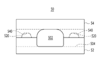
도 2는 본 발명의 실시 예에 따른 집수식 투수블록의 시공 단면도.
도 3는 도 1에 나타난 블록 본체의 평면도.
도 4는 도 1 내지 도 2에 도시된 우수유도블록의 분리 사시도.
도 5는 도 4에 도시된 우수유도블록의 결합 측면도.
도 6은 우수유도블록의 바람직한 다른 실시 예를 나타낸 측면도.
도 7은 우천 시 집수관을 통해 처리 가능한 양의 우수가 유입된 경우 우수의 흐름을 나타낸 본 발명의 작동 상태도.
도 8은 집중호우 등으로 인하여 집수관의 처리 용량보다 많은 양의 우수가 한꺼번에 유입된 경우 우수의 흐름을 나타낸 본 발명의 다른 작동 상태도.1 is an exploded perspective view of a water collecting permeable block according to an embodiment of the present invention;
2 is a construction cross-sectional view of a water-collecting permeable block according to an embodiment of the present invention.
3 is a plan view of the block body shown in Fig.
FIG. 4 is an exploded perspective view of the storm relief block shown in FIGS. 1 and 2. FIG.
Fig. 5 is an assembled side view of the abdominal guidance block shown in Fig. 4; Fig.
Figure 6 is a side view of another preferred embodiment of the abdominal guidance block.
FIG. 7 is an operating state diagram of the present invention showing the flow of stormwater when a stormable stormwater can be flowed through a stormwater line during rainfall. FIG.
FIG. 8 is another operating state of the present invention showing a flow of stormwater when a stormwater having a volume greater than the treatment capacity of the collector pipe due to heavy rain or the like is simultaneously introduced.
이하, 명세서에서 사용한 용어는 단지 특정한 실시 예를 설명하기 위해 사용된 것으로, 본 발명을 한정하려는 의도가 아니다. 단수의 표현은 문맥상 명백하게 다르게 뜻하지 않는 한, 복수의 표현을 포함한다. 본 명세서에서 "포함하다" 또는 "가지다" 등의 용어는 명세서상에 기재된 특징, 숫자, 단계, 동작, 구성요소, 부품 또는 이들을 조합한 것이 존재함을 지정하려는 것이지, 하나 또는 그 이상의 다른 특징들이나 숫자, 단계, 동작, 구성요소, 부품 또는 이들을 조합한 것들의 존재 또는 부가 가능성을 미리 배제하지 않는 것으로 이해되어야 한다.Hereinafter, the terminology used in the specification is used only to describe a specific embodiment and is not intended to limit the present invention. The singular expressions include plural expressions unless the context clearly dictates otherwise. It is to be understood that the terms "comprises", "having", and the like in the specification are intended to specify the presence of stated features, integers, steps, operations, elements, components, or combinations thereof, But do not preclude the presence or addition of one or more other features, integers, steps, operations, elements, parts, or combinations thereof.
또한, 제1, 제2 등의 용어는 다양한 구성요소들을 설명하는데 사용될 수 있지만, 상기 구성요소들은 상기 용어들에 의해 한정되어서는 안 된다. 상기 용어들은 하나의 구성요소를 다른 구성요소로부터 구별하는 목적으로만 사용된다.Also, the terms first, second, etc. may be used to describe various components, but the components should not be limited by the terms. The terms are used only for the purpose of distinguishing one component from another.
더하여, 명세서에 기재된 "…부", "…유닛", "…모듈" 등의 용어는 적어도 하나의 기능이나 동작을 처리하는 단위를 의미하며, 이는 하드웨어나 소프트웨어 또는 하드웨어 및 소프트웨어의 결합으로 구현될 수 있다.In addition, the terms " part, "" unit," " module, "and the like, which are described in the specification, refer to a unit for processing at least one function or operation, which may be implemented by hardware or software or a combination of hardware and software .
첨부 도면을 참조하여 설명함에 있어, 동일한 구성 요소에 대해서는 동일도면 참조부호를 부여하기로 하며 이에 대한 중복되는 설명은 생략하기로 한다. 그리고 본 발명을 설명함에 있어서 관련된 공지 기술에 대한 구체적인 설명이 본 발명의 요지를 불필요하게 흐릴 수 있다고 판단되는 경우 그 상세한 설명을 생략한다.In the following description with reference to the accompanying drawings, the same reference numerals are given to the same constituent elements, and a duplicate description thereof will be omitted. In the following description, well-known functions or constructions are not described in detail since they would obscure the invention in unnecessary detail.
이하, 본 발명의 바람직한 실시 예를 첨부도면을 참조하여 상세히 설명한다. Hereinafter, preferred embodiments of the present invention will be described in detail with reference to the accompanying drawings.
도 1은 본 발명의 실시 예에 따른 집수식 투수블록의 분해 사시도이며, 도 2는 본 발명의 실시 예에 따른 집수식 투수블록의 시공 단면도이다. 그리고 도 3는 도 1에 나타난 블록 본체의 평면도이며, 도 4는 도 1 내지 도 2에 도시된 우수유도블록의 분리 사시도이고, 도 5는 도 4에 도시된 우수유도블록의 결합 측면도이다.FIG. 1 is an exploded perspective view of a water collecting water receiving block according to an embodiment of the present invention, and FIG. 2 is a construction sectional view of a water collecting water receiving block according to an embodiment of the present invention. And FIG. 3 is a plan view of the block body shown in FIG. 1, FIG. 4 is an exploded perspective view of the rainbow guide block shown in FIGS. 1 and 2, and FIG. 5 is an assembled side view of the rainbow guide block shown in FIG.
도 1 내지 도 5를 참조하면, 본 발명의 실시 예에 따른 집수식 투수블록(1)은, 우천 시 빗물을 신속하게 지반 내로 투수시킬 수 있도록 한 보도 또는 차도의 노면 자재로서, 블록 본체(10), 블록 본체(10) 상부의 투수판(20), 블록 본체(10)와 연결되는 집수관(40), 우수에 포함된 오염물질을 걸러내는 포집망(30) 및 블록 본체(10)를 둘러싸는 복수의 우수유도블록(50)으로 구성된다.1 to 5, a water collecting
블록 본체(10)는 중앙에 집수부(15)가 형성되고, 측면에 일정한 간격으로 측면 투수홀(17)이 형성된 개방형 박스모양으로 구성된다. 블록 본체(10)는 그 상부에 설치되는 상기 투수판(20)과 하부에 설치되는 집수관(40)을 이어주며, 상기 투수판(20)을 통해 유입되는 우수가 집수관(40)으로 자연스럽게 흘러 들어갈 수 있도록 기능하는 경사판(14)을 내부에 구비한다.The
블록 본체(10)는 구체적으로, 블록 본체(10)의 중앙에 형성되며 상부와 하부가 개방된 중공의 상기 집수부(15)를 포함한다. 집수부(15) 둘레를 유도부(12)가 둘러싸며, 유도부(12) 내부에는 상기 집수부(15)를 향하여 하향 경사지게 경사판(14)이 설치된다. The
경사판(14)에 의하여 유도부(12)는 상부가 개방된 상부 공간(120)과 하부에 투수구멍(125)이 형성된 하부 공간(122)으로 구획되며, 유도부(12)의 측면에 상기 측면 투수홀(17)이 형성된다. The
유도부(12)는 또한, 격벽(13)에 의해 복수의 우수유도 셀(부호 생략)로 분할 구획될 수 있으며, 격벽(13)에 의해 구획된 우수유도 셀에 각각에 경사판(14)이 블록 본체(10) 중앙의 상기 상기 집수부(15)를 향하도록 하나씩 설치될 수 있다. 이에 따라 투수판(20)을 통해 유입된 우수는 각각의 우수유도 셀의 경사판(14)을 통해 집수부(15) 측으로 자연스럽게 모이게 되고, 집수부(15)를 통해 상기 집수관(40)으로 낙하 유입된다. The
투수판(20)은 상기 블록 본체(10) 상부에 설치되어 블록 본체(10)의 상측 개구를 덮는다. 투수판(20)에는 우수가 상기 블록 본체(10) 내부로 유입될 수 있도록 작은 크기(대략 2 ~ 3mm)의 구멍(200)이 다수 형성되어 있다. 투수판(20)은 블록 본체(10)의 면적에 대응되는 크기의 단일 판상체 또는 상기 격벽(13)에 의해 구획되는 우수유도 셀에 대응되는 크기로 분할 형성될 수 있다. The
집수부(15) 위치에 대응되는 투수판(20)의 일부가 상기 집수부(15) 직경에 대응되거나 그에 상응하는 크기로 개구될 수 있으며, 그 개구된 부분에는 다수의 구멍(220)이 형성된 유지보수덮개(22)가 분리 가능하게 설치될 수 있다.A part of the
이에 따라, 필요에 따라 유지보수덮개(22)를 분리하여 집수관(40) 내부에 축적된 오염물질을 제거할 수 있다. 즉 시간 경과에 따라 집수관(40)의 내부에 설치된 포집망(30)에 많은 오염물질이 쌓인 경우, 상기 유지보수덮개(22)를 분리하여 집수관(40) 내부의 포집망(30)을 외부로 빼내 세척 후 다시 설치하거나, 포집망(30)에 포획된 오염물질만을 제거함으로써 투수 성능을 회복시킬 수 있다.Accordingly, if necessary, the
집수관(40)은 상부가 개구된 통형, 예를 들면 원통 구조일 수 있다. 도 2에 도시된 바와 같이, 집수관(40)은 앙카(60)와 같은 고정수단을 통해 지층(A)에 고정될 수 있으며, 상기 블록 본체(10)의 집수부(15) 하단에 연결된다. 집수관(40)은 시공 시 상기 지층(A) 상부의 모래로 이루어진 투수표층(C)과 자갈들로 이루어진 투수기층(B)에 매립되며, 상기 투수기층(B)에 매립된 부분의 측면부에 투수구멍(400)이 다수 형성된다.The
이에 따라, 블록 본체(10)의 집수부(15)를 통해 집수관(40)으로 유입된 우수는 중간에 후술하는 포집망(30)을 통과하면서 오염물질이 걸러진 상태로 상기 투수구멍(400)을 통해 투수기층(B)으로 배출된다. 즉 우수와 함께 상기 집수관(40)에 유입된 오염물질은 필터로서 기능하는 상기 포집망(30)을 통해 걸러지고 정화 처리된 우수만이 투수기층(B)으로 배출되는 것이다. As a result, the rainwater flowing into the collecting
투수구멍(400)은 집수관(40)의 바닥 측면에서부터 상기 투수기층(B)의 높이(H)에 대응되는 높이에 걸쳐 상기 집수관(40)의 측면부에 일정한 패턴으로 형성될 수 있다. 그리고 집수관(40)이 지층(A) 표면에 안정적으로 접지될 수 있도록 집수관(40)의 저부 둘레에는 접지날개(42)가 형성되고, 접지날개(42)에는 집수관(40)이 상기 앙카(60) 등에 의해 지층(A)에 견고히 고정될 수 있도록 앙카홀(420)이 형성된다.The
포집망(30)은 상기 집수관(40) 내부에 설치되어 상기 투수구멍(125)을 통해 투수기층(B)으로 배출되는 우수에 포함된 오염물질을 걸러내는 일종의 필터 역할을 한다. 이러한 포집망(30)은 상부가 개구된 용기(Vessel) 모양의 스크린망 구성일 수 있으며, 상기 투수기층(B)의 높이(H)에 대응되는 높이로 형성될 수 있다. 또한 집수관(40)으로부터 분리하여 내부 오염물질을 제거할 수 있도록 집수관(40)과는 독립된 구성일 수 있다.The collection net 30 functions as a kind of filter installed inside the
우수유도블록(50)은 상기 블록 본체(10) 둘레에 연접 설치된다. 우수유도블록(50)은 복수로 구성되며, 각각의 내부에 형성된 유로 중 어느 한 방향의 유로(우수유도블록들을 상호 연접시킨 방향으로 형성된 유로, 도면상 제1 방향 유로(502))가 서로 연통되도록 이웃하는 우수유도블록(50)끼리 서로 연결 또는 마주하는 면이 서로 접하도록 설치될 수 있다.The
우수유도블록(50)에는 중앙부가 직각으로 교차되는 두 개의 유로가 형성된다. 두 개의 유로 중 하나는 이웃하는 우수유도블록(50) 사이를 우수가 이동할 수 있도록 형성되는 제1 방향 유로(502)이며, 다른 하나는 상기 제1 방향 유로(502)와 교차하며 상기 블록 본체(10)의 측면 투수홀(17)과 연통되어 우수가 블록 본체(10)에 유입될 수 있는 경로를 형성하는 제2 방향 유로(504)일 수 있다.In the
도 2에 도시된 바와 같이, 우수유도블록(50)은 블록 본체(10) 상부에 투수판(20)이 결합된 높이에 대응되는 높이로 형성될 수 있으며, 도 4 및 도 5에 도시된 바와 같이, 모래로 이루어진 상기 투수표층(C) 상에 설치되는 하부 블록(52)과, 상기 하부 블록(52) 상부에 분리 가능하게 결합되는 상부 블록(54)으로 구성될 수 있다.2, the storm
하부 블록(52)의 네 모서리 돌출부 상면과 여기에 대응되는 상부 블록(54)의 네 모서리 돌출부 하면에는 시공 시 하부 블록(52)에 대한 상부 블록(54)의 이탈 또는 어긋남 방지를 위해 볼록 돌기(520) 및 결합홈(540)이 각각 형성될 수 있다. 물론 반대로 상부 블록(54)의 네 모서리 돌출부 하면에 볼록 돌기가 형성되고 하부 블록(52)의 네 모서리 돌출부 상면에 결합홈이 형성될 수도 있다. The upper surface of the four corner protrusions of the
도 6은 우수유도블록의 바람직한 다른 실시 예를 도시한 측면도로서, 우수유도블록의 상기 하부 블록(52)의 제1 방향 유로(502)와 제2 방향 유로(504)가 서로 교차하는 지점 또는 제1 방향 유로(502)와 제2 방향 유로(504) 중 적어도 하나의 유로에는 유로를 따라 흐르는 우수 중 일부를 투수표층에 투수시키는 소정 크기의 투수홀(525)이 하나 이상 형성될 수 있다. 6 is a side view showing another preferred embodiment of the storm valve guide block in which the first
이때 각 투수홀(525)에는 해당 투수홀(525)에 대응되는 크기의 여과부재, 예컨대, 거름망이나 부직포 재질의 필터(도시 생략)가 각각 설치될 수 있다. 이 경우 투수홀(525)을 통해 투수표층(C)으로 투수가 행해짐에 있어, 우수에 포함된 미세 오염물에 대한 1차 정화 처리 후 투수표층으로 우수가 투수됨으로써 투수표층(C) 표면의 오염물질 누적으로 인한 투수성능 저하를 최소화할 수 있다.At this time, a filtering member having a size corresponding to the
이하 우천 시 전술한 구성의 투수블록에 의한 우수 처리 과정을 도면을 참조하여 간단하게 살펴보기로 한다. Hereinafter, the stormwater treatment process by the permeable block having the above-described structure will be briefly described with reference to the drawings.
도 7 및 도 8은 우천 시 투수블록에 유입된 우수가 구체적으로 어떠한 경로를 통해 지반 측에 투수되는지를 도시한 본 발명의 작동 상태도로서, 도 7은 우천 시 집수관을 통해 처리 가능한 양의 우수가 유입된 경우 우수의 흐름을 나타내고 있고, 도 8은 집중호우 등으로 인하여 집수관의 처리 용량보다 많은 양의 우수가 한꺼번에 유입된 경우 우수의 흐름을 나타내고 있다.FIGS. 7 and 8 are operation states of the present invention showing how the stormwater flowing into the water-permeable block during rainfall is poured to the ground side through concrete paths. FIG. And FIG. 8 shows the flow of stormwater when the amount of storm that is larger than the treated capacity of the water collecting pipe due to heavy rain or the like is introduced at a time.
도 7을 먼저 참조하면, 우수는 블록 본체(10) 상부의 투수판(20)과 유지보수덮개(22)의 구멍을 통해 블록 본체(10) 내부로 유입된다. 또한 일부 우수가 블록 본체(10) 둘레에 설치되는 각각의 우수유도블록(50)을 통해서도 블록 본체(10) 내부로 유입된다. 7, the storm flows into the
우수유도블록(50)을 통해 유입되는 우수의 대부분은 유도부(12) 저면의 투수구멍(125)을 통해 투수표층(C)에 투수되며, 다른 일부는 집수부(15) 측으로 이동된다.Most of the rainwater flowing through the
블록 본체(10)에 유입되는 우수 중 상기 투수판(20) 및 유지보수덮개(22)를 통해 유입된 우수는 블록 본체(10) 내부의 경사판(14)을 거쳐 집수부(15) 측으로 자연스럽게 이동하게 되고, 집수부(15)를 거쳐 블록 본체(10) 하부의 집수관(40)으로 낙하 유입된다. 그리고 집수관(40) 내부의 포집망(30)을 통과하면서 오염물질이 걸러진 상태로 투수구멍(400)을 통해 투수기층(B)으로 배출된다.The rainwater flowing through the water
즉 우수와 함께 상기 집수관(40)에 유입된 오염물질은 필터로서 기능하는 상기 포집망(30)을 통해 걸러지고 정화 처리된 우수만이 투수기층(B) 측으로 배출되는 것이며, 포집망(30)에 많은 오염물질이 쌓였을 경우 유지보수덮개(22)를 분리하여 집수관(40) 내부의 포집망(30)을 외부로 빼내 세척하거나, 포집망(30)에 포획된 오염물질만을 제거함으로써 투수 성능을 회복시킬 수 있다.That is, the contaminants introduced into the
한편, 도 8과 같이 집중호우로 인하여 집수관(40)의 처리 용량보다 많은 양의 우수가 한꺼번에 유입된 경우에는, 집수관(40)으로 유입되었던 일부 우수가 블록 본체(10)의 경사판(14) 하부의 유도부(12) 공간으로 오버 플로우(Over flow)되어 유도부(12) 저면의 투수구멍(125)을 통해 투수표층(C)에 투수됨으로써, 집중호우에도 우수가 지상 측으로 역류하는 것을 최대한 억제할 수 있다.8, some of the storm that has flowed into the collecting
이상에서 살펴본 본 발명의 실시 예에 따른 투수블록에 의하면, 우천시 다량의 우수를 저수하고 신속하게 지반에 투수시킬 수 있으며, 시간이 경과함에 따라 집수관의 내부에 오염물질이 쌓이더라도 투수판 중앙의 유지보수덮개를 통해 포집망에 포획된 오염물질을 용이하게 제거할 수 있어 안정적인 투수 성능이 지속적으로 발휘될 수 있다.According to the water permeable block according to the embodiment of the present invention as described above, a large amount of stormwater can be stored at the time of rainstorming and can be rapidly permeated to the ground, and even if contaminants are accumulated in the water pipe with time, The pollutant trapped in the trapping net can be easily removed through the repair cover, so that stable permeability can be continuously exhibited.
또한, 넓은 면적에서 우수를 받아 가운데 집수관을 통해 집수한 후 오염물질을 제거한 상태로 직접 투수기층으로 투수시킴으로써, 투수기층이 오염물질에 의해 오염되거나 오염물질로 인해 투수기층의 공극이 막혀 투수성이 저하되는 것을 막을 수 있다.In addition, by receiving water from a large area and collecting the water through the water collecting pipe, the water permeable layer is contaminated by the pollutants or the pores of the permeable layer are clogged due to pollutants, Can be prevented from lowering.
또한, 집수관의 처리 용량에 비해 한꺼번에 많은 양의 우수가 들어오더라도 주변의 우수유도블록이나 블록 본체의 유도부 측으로 우수를 오버 플로우(Over flow)시켜 투수표층에 직접 투수할 수 있도록 구성됨으로써, 집중호우 시 우수의 역류를 최대한 억제할 수 있다.In addition, even if a large amount of storm water enters at a time compared with the treatment capacity of the collecting water pipe, the stormwater can be over-flowed to the vicinity of the outer storm block or the guide portion of the block body, It is possible to suppress the backflow of stormwater rain as much as possible.
10 : 블록 본체
12 : 유도부
13 : 격벽
14 : 경사판
15 : 집수부
17 : 측면 투수홀
20 : 투수판
22 : 유지보수덮개
30 : 포집망
40 : 집수관
42 : 접지날개
50 : 우수유도블록
52 : 하부 블록
54 : 상부 블록
60 : 앙카
120 : 상부 공간
122 : 하부 공간
125 : 투수구멍
200, 220 : 구멍
400 : 투수구멍
420 : 앙카홀
502 : 제1 방향 유로
504 : 제2 방향 유로
520 : 볼록 돌기
540 : 결합홈
A : 지층
B : 투수기층
C : 투수표층
H : 투수기층의 높이
10: block body 12: guide part
13: partition wall 14: swash plate
15: collecting part 17: side penetrating hole
20: Pitch plate 22: Maintenance cover
30: collection network 40: house water pipe
42: grounding wing 50:
52: lower block 54: upper block
60: anchor 120: upper space
122: lower space 125: water hole
200, 220: hole 400: pitch hole
420: anchor hole 502: first directional flow path
504: second direction flow path 520: convex projection
540: coupling groove A: stratum
B: Permeable layer C: Permeable surface layer
H: Height of the permeable layer
Claims (9)
중앙에 집수부가 형성되고, 측면에 일정한 간격으로 측면 투수홀이 형성된 박스모양의 개방형 블록 본체;
상기 블록 본체 상부에 설치되며, 우수가 상기 블록 본체 내부로 유입될 수 있도록 다수의 구멍이 형성된 투수판;
상기 블록 본체의 집수부 하단에 연결되고, 모래로 이루어진 투수표층과 자갈들로 이루어진 투수기층에 매립되며, 상기 투수기층에 매립된 부분의 측면부에 다수의 투수구멍을 갖는 상부가 개구된 통형 구조의 집수관;
상기 집수관 내부에 설치되며, 상기 투수구멍을 통해 투수기층으로 배출되는 우수에 포함된 오염물질을 걸러내는 포집망; 및
상기 블록 본체 둘레에 연접 설치되며, 내측에 제1 방향 유로와, 제1 방향 유로와 교차하며 상기 측면 투수홀과 연통되는 제2 방향 유로가 형성된 복수의 우수유도블록;을 포함하는 집수식 투수블록.
It is used as the road surface material of a sidewalk or a roadway, and it is possible to quickly transmit rainwater into the ground during rainy weather.
A box-shaped open block body having a water collecting part formed at the center thereof and formed with side penetrating holes at regular intervals on its side;
A plurality of holes formed in the block body to allow the storm to flow into the block body;
A tubular structure having an upper portion opened at a side portion of a portion buried in the permeable substrate layer and having a plurality of water permeable holes, the tubular structure being connected to a lower end of the collecting portion of the block body, House water pipes;
A trapping mesh installed in the water collecting pipe to filter contaminants contained in the rainwater discharged to the water permeable layer through the watertight hole; And
And a plurality of storm valve blocks provided adjacent to the block body and having a first directional flow path and a second directional flow path intersecting the first directional flow path and communicating with the side clearance holes, .
상기 블록 본체는,
블록 본체 중앙에 형성되며, 상부와 하부가 개방된 중공의 집수부;
상기 집수부를 둘러싸도록 구성되며, 상부가 개방되고 하부에 투수구멍이 형성되며, 측면에 상기 측면 투수홀이 형성된 유도부; 및
상기 유도부 내부에 상기 집수부를 향하여 하향 경사지게 설치되는 경사판;으로 구성되는 것을 특징으로 하는 집수식 투수블록.
The method according to claim 1,
The block body includes:
A hollow collecting part formed at the center of the block body and having upper and lower openings;
A guiding part which is configured to surround the collecting part, the upper part of which is open, the lower part of which has a water hole, and the side surface of which is formed a side hole; And
And a swash plate installed inside the guide portion so as to be inclined downward toward the collecting portion.
상기 유도부는 격벽에 의해 복수의 우수유도 셀로 구획되는 것을 특징으로 하는 집수식 투수블록.
3. The method of claim 2,
And the induction part is partitioned into a plurality of storm cell by a partition wall.
상기 집수부 위치에 대응되는 투수판의 일부가 상기 집수부 직경에 대응되는 크기로 개구되고, 개구된 부분에 다수의 구멍이 형성된 유지보수덮개가 분리 가능하게 설치되는 것을 특징으로 하는 집수식 투수블록.
The method according to claim 1,
Wherein a part of the permeable plate corresponding to the position of the water collecting part is opened to a size corresponding to the diameter of the water collecting part and a maintenance lid having a plurality of holes formed in the opened part is detachably installed.
상기 집수관의 저부 둘레에 접지날개가 형성되고, 상기 접지날개에는 상기 투수기층 하부의 지층 표면에 상기 집수관을 고정시킬 수 있도록 앙카홀이 형성된 것을 특징으로 하는 집수식 투수블록.
The method according to claim 1,
Wherein a ground wing is formed around the bottom of the collector pipe and an anchor hole is formed in the ground wing so as to fix the collector pipe to the surface of the ground layer below the permeable layer.
상기 포집망은 상부가 개구된 용기 형태로 구성되며, 상기 투수기층에 대응되는 높이로 형성되는 것을 특징으로 하는 집수식 투수블록.
The method according to claim 1,
Wherein the collecting net is formed in a container shape having an open upper part and is formed to have a height corresponding to the water permeable layer.
상기 포집망이 집수관으로부터 분리되는 것을 특징으로 하는 집수식 투수블록.
7. The method according to claim 1 or 6,
And the collecting net is separated from the collecting pipe.
상기 우수유도블록은 블록 본체 상부에 투수판이 결합된 높이로 형성되며, 상기 투수표층 상에 설치되는 하부 블록과, 하부 블록 상부에 결합되는 상부 블록으로 구성되는 것을 특징으로 하는 집수식 투수블록.
The method according to claim 1,
Wherein the stormwater blocking block comprises a lower block formed on the water permeable surface layer and an upper block coupled to an upper portion of the lower block, the height of the stormwater block coupled to the upper portion of the block body.
상기 하부 블록의 네 모서리 돌출부 상면에 볼록 돌기가 각각 형성되고,
상기 상부 블록의 네 모서리 돌출부 하면에 상기 볼록 돌기에 대응되는 결합홈이 형성된 것을 특징으로 하는 집수식 투수블록.
9. The method of claim 8,
Convex projections are formed on the upper surface of the four corner projections of the lower block,
And an engaging groove corresponding to the convex protrusion is formed on a bottom surface of the four corner protrusions of the upper block.
Priority Applications (1)
| Application Number | Priority Date | Filing Date | Title |
|---|---|---|---|
| KR1020160173818A KR20180071063A (en) | 2016-12-19 | 2016-12-19 | Water catchment type water permeable block |
Applications Claiming Priority (1)
| Application Number | Priority Date | Filing Date | Title |
|---|---|---|---|
| KR1020160173818A KR20180071063A (en) | 2016-12-19 | 2016-12-19 | Water catchment type water permeable block |
Publications (1)
| Publication Number | Publication Date |
|---|---|
| KR20180071063A true KR20180071063A (en) | 2018-06-27 |
Family
ID=62789836
Family Applications (1)
| Application Number | Title | Priority Date | Filing Date |
|---|---|---|---|
| KR1020160173818A KR20180071063A (en) | 2016-12-19 | 2016-12-19 | Water catchment type water permeable block |
Country Status (1)
| Country | Link |
|---|---|
| KR (1) | KR20180071063A (en) |
Cited By (6)
| Publication number | Priority date | Publication date | Assignee | Title |
|---|---|---|---|---|
| CN108978397A (en) * | 2018-07-05 | 2018-12-11 | 浙江省水利河口研究院 | A kind of stagnant device of side-type water on urban streets row storage |
| CN110409558A (en) * | 2019-08-15 | 2019-11-05 | 浙江省交通规划设计研究院有限公司 | The rainwater utilization system and construction method of greenbelt |
| WO2019245202A1 (en) | 2018-06-20 | 2019-12-26 | 주식회사 엘지화학 | Separator for electrochemical device, method for manufacturing same, and electrochemical device comprising same |
| CN111305362A (en) * | 2020-03-30 | 2020-06-19 | 徐州工程学院 | Park road infiltration layer construction scheme based on initial rainwater interception and purification |
| CN112281577A (en) * | 2020-09-03 | 2021-01-29 | 宁波汇洲生态建设有限公司 | High-pressure-resistance concrete garden road with water permeability |
| KR102505041B1 (en) * | 2022-10-18 | 2023-02-28 | 남옥랑 | Ground surface water permeability structure with improved water permeation efficiency |
Citations (1)
| Publication number | Priority date | Publication date | Assignee | Title |
|---|---|---|---|---|
| KR200451992Y1 (en) | 2008-11-26 | 2011-01-25 | 김진완 | Pavement Case for Footpath Block having Water-Permeable Pad |
-
2016
- 2016-12-19 KR KR1020160173818A patent/KR20180071063A/en not_active Application Discontinuation
Patent Citations (1)
| Publication number | Priority date | Publication date | Assignee | Title |
|---|---|---|---|---|
| KR200451992Y1 (en) | 2008-11-26 | 2011-01-25 | 김진완 | Pavement Case for Footpath Block having Water-Permeable Pad |
Cited By (8)
| Publication number | Priority date | Publication date | Assignee | Title |
|---|---|---|---|---|
| WO2019245202A1 (en) | 2018-06-20 | 2019-12-26 | 주식회사 엘지화학 | Separator for electrochemical device, method for manufacturing same, and electrochemical device comprising same |
| CN108978397A (en) * | 2018-07-05 | 2018-12-11 | 浙江省水利河口研究院 | A kind of stagnant device of side-type water on urban streets row storage |
| CN110409558A (en) * | 2019-08-15 | 2019-11-05 | 浙江省交通规划设计研究院有限公司 | The rainwater utilization system and construction method of greenbelt |
| CN111305362A (en) * | 2020-03-30 | 2020-06-19 | 徐州工程学院 | Park road infiltration layer construction scheme based on initial rainwater interception and purification |
| CN111305362B (en) * | 2020-03-30 | 2020-12-01 | 徐州工程学院 | Structure of seepage layer under park road based on initial rainwater closure purification |
| CN112281577A (en) * | 2020-09-03 | 2021-01-29 | 宁波汇洲生态建设有限公司 | High-pressure-resistance concrete garden road with water permeability |
| CN112281577B (en) * | 2020-09-03 | 2022-03-11 | 宁波汇洲生态建设有限公司 | High-pressure-resistance concrete garden road with water permeability |
| KR102505041B1 (en) * | 2022-10-18 | 2023-02-28 | 남옥랑 | Ground surface water permeability structure with improved water permeation efficiency |
Similar Documents
| Publication | Publication Date | Title |
|---|---|---|
| KR20180071063A (en) | Water catchment type water permeable block | |
| KR101051778B1 (en) | Rainwater storage block, water collecting and filtering apparatus and rainwater treating system | |
| KR101703319B1 (en) | Rainwater permeate retention system | |
| KR101874284B1 (en) | Water Cycling System having Drain Road Boundary Stone | |
| KR20180124286A (en) | The Permeable sidewalk block construction method for stormwater runoff reduction | |
| KR101205223B1 (en) | System for treating infiltration water | |
| KR101977695B1 (en) | Penetration Gauges Structure | |
| KR101510615B1 (en) | Penetration type rainwater storage tank and construction method of the same | |
| KR20150114224A (en) | infiltration institution of rainwater in rainwater treatment | |
| JP2009127359A (en) | Drainage structure for side ditch | |
| KR101043662B1 (en) | Rain water draining side ditch assembly | |
| JP6106136B2 (en) | Osmosis system | |
| KR101331596B1 (en) | Permeate piping the initial rain purification | |
| KR101380776B1 (en) | A Monolithic street tree box with side gutter | |
| KR20160087099A (en) | Drain apparatus for bridge having horseshoe arch shape | |
| JP4608366B2 (en) | Underdrain drainage structure and rainwater infiltration treatment method | |
| KR101906075B1 (en) | Road side ditch having seepage paving-material | |
| JP2006322148A (en) | Underground storage permeation facility of rainwater | |
| KR101671768B1 (en) | Infiltration trench with inner inlet | |
| KR101055652B1 (en) | Infiltration trench having natural water circulation and make better use of a space the use of effective materials | |
| KR20100059750A (en) | Hoding tank for purification, dual-structure drainpipe and infiltration and detention system with them | |
| JPH04146Y2 (en) | ||
| KR20160150141A (en) | Water-permeable pavement and water circulation system | |
| KR101663914B1 (en) | Rainwater infilration structures | |
| KR100978238B1 (en) | Hoding tank for purification, Dual-structure drainpipe and Infiltration and detention system with them |
Legal Events
| Date | Code | Title | Description |
|---|---|---|---|
| A201 | Request for examination | ||
| E902 | Notification of reason for refusal | ||
| E601 | Decision to refuse application |