KR101671768B1 - Infiltration trench with inner inlet - Google Patents
Infiltration trench with inner inlet Download PDFInfo
- Publication number
- KR101671768B1 KR101671768B1 KR1020160033622A KR20160033622A KR101671768B1 KR 101671768 B1 KR101671768 B1 KR 101671768B1 KR 1020160033622 A KR1020160033622 A KR 1020160033622A KR 20160033622 A KR20160033622 A KR 20160033622A KR 101671768 B1 KR101671768 B1 KR 101671768B1
- Authority
- KR
- South Korea
- Prior art keywords
- infiltration
- water
- ditch
- trench
- rainwater
- Prior art date
- Legal status (The legal status is an assumption and is not a legal conclusion. Google has not performed a legal analysis and makes no representation as to the accuracy of the status listed.)
- Active
Links
Images


Classifications
-
- E—FIXED CONSTRUCTIONS
- E03—WATER SUPPLY; SEWERAGE
- E03F—SEWERS; CESSPOOLS
- E03F5/00—Sewerage structures
- E03F5/10—Collecting-tanks; Equalising-tanks for regulating the run-off; Laying-up basins
- E03F5/101—Dedicated additional structures, interposed or parallel to the sewer system
-
- B—PERFORMING OPERATIONS; TRANSPORTING
- B01—PHYSICAL OR CHEMICAL PROCESSES OR APPARATUS IN GENERAL
- B01D—SEPARATION
- B01D24/00—Filters comprising loose filtering material, i.e. filtering material without any binder between the individual particles or fibres thereof
- B01D24/02—Filters comprising loose filtering material, i.e. filtering material without any binder between the individual particles or fibres thereof with the filter bed stationary during the filtration
- B01D24/20—Filters comprising loose filtering material, i.e. filtering material without any binder between the individual particles or fibres thereof with the filter bed stationary during the filtration the filtering material being provided in an open container
-
- C—CHEMISTRY; METALLURGY
- C02—TREATMENT OF WATER, WASTE WATER, SEWAGE, OR SLUDGE
- C02F—TREATMENT OF WATER, WASTE WATER, SEWAGE, OR SLUDGE
- C02F1/00—Treatment of water, waste water, or sewage
- C02F1/001—Processes for the treatment of water whereby the filtration technique is of importance
-
- E—FIXED CONSTRUCTIONS
- E03—WATER SUPPLY; SEWERAGE
- E03F—SEWERS; CESSPOOLS
- E03F1/00—Methods, systems, or installations for draining-off sewage or storm water
- E03F1/002—Methods, systems, or installations for draining-off sewage or storm water with disposal into the ground, e.g. via dry wells
-
- E—FIXED CONSTRUCTIONS
- E03—WATER SUPPLY; SEWERAGE
- E03F—SEWERS; CESSPOOLS
- E03F5/00—Sewerage structures
- E03F5/14—Devices for separating liquid or solid substances from sewage, e.g. sand or sludge traps, rakes or grates
-
- B—PERFORMING OPERATIONS; TRANSPORTING
- B01—PHYSICAL OR CHEMICAL PROCESSES OR APPARATUS IN GENERAL
- B01D—SEPARATION
- B01D2221/00—Applications of separation devices
- B01D2221/12—Separation devices for treating rain or storm water
-
- C—CHEMISTRY; METALLURGY
- C02—TREATMENT OF WATER, WASTE WATER, SEWAGE, OR SLUDGE
- C02F—TREATMENT OF WATER, WASTE WATER, SEWAGE, OR SLUDGE
- C02F2103/00—Nature of the water, waste water, sewage or sludge to be treated
- C02F2103/001—Runoff or storm water
Landscapes
- Life Sciences & Earth Sciences (AREA)
- Engineering & Computer Science (AREA)
- Hydrology & Water Resources (AREA)
- Water Supply & Treatment (AREA)
- Health & Medical Sciences (AREA)
- Public Health (AREA)
- Chemical & Material Sciences (AREA)
- Chemical Kinetics & Catalysis (AREA)
- Environmental & Geological Engineering (AREA)
- Organic Chemistry (AREA)
- Sewage (AREA)
Abstract
본원발명은 강우유출수에 함유된 비점오염물질을 저감할 수 있음과 아울러 비점오염물질이 저감된 처리수를 지중으로 침투시켜 지하수를 확충하는 데 기여하고자 한다. 아울러 전처리조에서 협잡물을 걸러냄으로써 여과조의 부하를 대폭 줄이고 여과 효율을 향상시킬 수 있을 뿐만 아니라, 집중 강우 시나 호우 시에 유입수가 범람하는 것을 방지하기 위한 함침형 배출 수단을 제공하고자 한다.
본원발명은 여재 또는 쇄석을 포함하는 여재층을 포함하고 유입되는 처리대상수를 하부 지반으로 침투시키는 침투도랑으로서, 상기 침투도랑은 집중 강우 시 처리대상수를 배수관로로 배출시키는 것을 특징으로 하는 침투도랑을 제공한다.The present invention is intended to contribute to the reduction of nonpoint pollutants contained in rainfall runoff and the penetration of treated water with reduced nonpoint pollutants into the ground to expand groundwater. In addition, filtration efficiency can be improved by filtering the contaminants in the pretreatment tank to greatly reduce the load on the filtration tank, and to provide an impregnation type discharge means for preventing inflow water from overflowing during heavy rainfall or heavy rainfall.
The present invention relates to an infiltration trench for infiltrating an inflowing treatment water into a lower ground including a filter material layer containing filter media or crushed stone, wherein the infiltration trench discharges water to be treated at the time of intensive rainfall to a drain pipe, Provide a ditch.
Description
본원발명은 침투도랑에 관한 것이다. 구체적으로는 강우유출수에 함유된 비점오염물질을 저감할 수 있음과 아울러 비점오염물질이 저감된 처리수를 지중으로 침투시켜 지하수를 확충하는 데 기여할 수 있는 침투도랑을 제공하고자 한다. 아울러 전처리조에서 협잡물을 걸러냄으로써 여과조의 부하를 대폭 줄이고 여과 효율을 향상시킬 수 있을 뿐만 아니라, 집중 강우 시나 호우 시에 유입수가 범람하는 것을 방지하고 강우중기이후의 수질이 양호한 빗물은 별도의 처리없이 신속하게 배제하기 위한 함침형 배출 수단을 제공하고자 한다.The present invention relates to penetration trenches. Specifically, it is intended to provide a penetration ditch capable of reducing nonpoint pollutants contained in rainwater runoff and contributing to expanding groundwater by infiltrating treatment water with reduced nonpoint pollutants into the ground. In addition, filtration efficiency can be improved by greatly reducing the load on the filtration tank by filtering the contaminants in the pretreatment tank. In addition, it is possible to prevent inflow water from overflowing during heavy rainfall or heavy rainfall, And to provide an impregnated discharge means for rapid exclusion.
도시화와 인구집중에 따라 우리의 생활주변은 도로와 건물로 뒤덮이고, 도시화, 산업화의 진전으로 토지 개발이 가속화되고 도로, 산업단지, 택지 등 불투수층 면적이 늘어남에 따라 비점오염물질에 의한 하천, 호소 등의 수질에 대한 악영향이 커지고 있다.Due to urbanization and population concentration, our living surroundings are covered with roads and buildings. As the development of urbanization and industrialization accelerates the development of land and the area of roads, industrial complexes and residential floors becomes larger, And the like are adversely affecting the water quality.
또한 비가 오면 빗물이 즉각적으로 포장된 도로와 우수관로를 따라 빠르게 이동하며 이동하는 동안 도로의 많은 비점오염물질을 함께 담아 하천으로 흘러간다. 지표면이 포장됨에 따라 흙을 통과해서 지하수가 되는 물의 양은 점점 줄어들고 고갈되어 버린다. 공원이나 정원에 남아 있는 수목의 식재 기반 토양은 빗물에 곧잘 씻겨 내려가고 딱딱하게 굳어 있어 땅속 생물을 부양하기도 빗물을 받아들여 지하수로 내려 보내기도 힘겨워진 상태이다.In addition, when it rains, rainwater moves quickly along packed roads and bridges, and flows into the river with many non-point pollutants along the road while moving. As the surface of the earth is packed, the amount of water that passes through the soil and becomes ground water gradually decreases and becomes exhausted. The vegetation-based soils in the parks and gardens are often washed down in the rainwater and hardened to harden the underground creatures. It is also difficult to take down the rainwater to the groundwater.
비점오염물질을 저감하는 시설로는 저류형, 침투형, 식생형, 장치형, 하수처리형 등이 있으나, 이는 오염수에 함유되어 있는 특정 오염물질을 제거하는 것이므로 도시 지역의 특성을 고려하여 강우유출수에 포함되어 있는 비점오염물질을 제거함과 동시에 비점오염물질이 제거된 강우유출수를 지하수로 유도하는 통합형 처리시설의 필요성이 대두된다.There are various types of facilities to reduce nonpoint pollutants such as reservoir type, infiltration type, vegetation type, device type and sewage treatment type. However, since this is to remove specific pollutants contained in polluted water, The need for an integrated treatment facility that removes non-point pollutants contained in the effluent and at the same time directs rainwater runoff from which non-point pollutants have been removed to groundwater.
침투도랑은 기본적으로 강우유출수를 처리하기 위하여 일정한 깊이로 굴착한 도랑에 자갈이나 돌을 충전하여 조성한 일종의 지하 저수조이다. 나아가 현장에 따라 침투도랑을 통하여 비점오염물질을 저감하기도 한다.The penetration ditch is basically a kind of underground water reservoir formed by filling gravel or stones in a ditch excavated at a certain depth to treat rain water runoff. Furthermore, non-point pollutants are reduced through infiltration ditches depending on the site.
본원발명은 침투도랑에 개량한 기술을 공개하고자 한다. 본원발명은 침투도랑의 유지관리 효율을 높이고, 침투도랑의 범람을 방지하고 한다. The present invention intends to disclose an improved technique for infiltration trenches. The present invention improves the maintenance efficiency of the infiltration ditch and prevents the flooding of the infiltration ditch.
대한민국 등록특허공보 제1035519호 식생형 비점오염 처리 도랑은 강우 유출수 등이 유입되는 개거(開渠)와 개거 상단에 결합되고 식물이 식재되는 식재판으로 구성되어 비점오염을 처리하는 식생 도랑을 제공한다는 점에서 본원발명과 일부 공통되는 점이 있다. 하지만, 본원발명은 집중 강우 시에 신속한 배수가 가능한 수단을 제공한다는 점에서 차이가 있다.Korean Patent Publication No. 1035519 A vegetation-type non-point pollution ditch provides a vegetation ditch that is composed of a dew point into which rainwater runoff flows and an edible plate where plants are planted, There are some points in common with the present invention. However, the present invention is different in that it provides a means for rapid drainage at the time of concentrated rainfall.
대한민국 공개특허공보 제2011-0138051호 생태도랑을 이용한 도시비점오염물질처리장치는 초기 빗물 비점오염물질 처리장치를 제공한다는 점에서 본원발명과 일부 공통되는 점이 있다. 하지만, 본원발명이 제공하는 집중 강우 시의 배수 수단에 대하여 공개되는 점이 없는바, 본원발명과는 차이가 있다.Korean Patent Laid-Open Publication No. 2011-0138051 DISCLOSURE OF THE INVENTION PROBLEMS TO BE SOLVED BY THE INVENTION In view of providing an apparatus for treating rainwater non-point pollutants in an initial stage, there is a point in common with the present invention. However, the present invention is different from the present invention in that there is no disclosure of the drain means at the time of the concentrated rain provided by the present invention.
본원발명은 침투도랑에 많은 양의 강우유출수가 유입되는 경우에도 범람하지 않고 안정적으로 유지될 수 있는 수단을 제공하고자 한다.The present invention seeks to provide a means that can be stably maintained without flooding even when a large amount of rainfall runoff flows into the infiltration trench.
상기의 과제를 해결하기 위하여 본원발명은, 여재 또는 쇄석을 포함하는 여재층을 포함하고 유입되는 처리대상수를 하부 지반으로 침투시키는 침투도랑으로서, 상기 침투도랑은 집중 강우 시 처리대상수를 배수관로로 배출시키는 것을 특징으로 하는 침투도랑을 제공한다. In order to solve the above problems, the present invention provides an infiltration trench for infiltrating an inflowing treatment water into a lower ground including a filter material layer containing a filter material or a crushed stone, And then discharging the molten metal into the trench.
본원발명은 상기 침투도랑의 하부에 다수의 침투공이 형성되어 처리대상수를 하부 지반으로 침투시키고, 상기 침투도랑의 내측에는 빗물받이가 설치되어 있되, 상기 빗물받이는 상기 배수관로와 연결되어 있는 것을 특징으로 할 수 있다.The present invention is characterized in that a plurality of infiltration holes are formed in the lower part of the infiltration trench to infiltrate water to be treated into the lower infiltration ground, and a rainwater receiver is installed inside the infiltration trench, wherein the rainwater receiver is connected to the water pipe .
상기 침투도랑의 앞에는 전처리조가 구비되고, 상기 전처리조로부터 처리대상수가 월류하여 상기 침투도랑으로 유입되고, 집중 강우 시에는 유입되는 처리대상수가 상기 침투도랑을 월류하여 유출수로로 배출되는 것을 특징으로 할 수 있다.The pretreatment tank is provided in front of the infiltration trench. The object to be treated flows from the pretreatment tank to the infiltration trench and flows into the infiltration trench. During intensive rainfall, the inflowing target water flows through the infiltration trench and is discharged to the effluent passage .
상기 빗물받이의 높이는 상기 여재층의 높이보다는 높고 상기 침투도랑의 외부벽보다는 낮게 형성되는 것을 특징으로 할 수 있다.The height of the rainwater receiver is higher than the height of the filter material layer and lower than the outer wall of the infiltration trench.
상기 침투도랑의 최상단에는 범람방지턱이 형성되어 집중 강우 시나 우기 시에 시설 외측으로 처리대상수가 범람하지 않도록 하는 것을 특징으로 할 수 있다.And an overflow preventing jaw is formed at the uppermost end of the infiltration trench so that the number of objects to be treated does not flood outside the facility during heavy rainfall or rainy season.
상기 빗물받이의 높이는 상기 여재층의 높이보다는 높고 상기 침투도랑의 범람방지턱보다는 낮게 형성되는 것을 특징으로 할 수 있다.And the height of the rainwater receiver is higher than the height of the filter material layer and lower than the height of the infiltration ditch.
본원발명은 침투도랑에 많은 양의 강우유출수가 유입되는 경우에도 범람하지 않고 안정적으로 유지될 수 있는 수단을 제공하고자 한다.The present invention seeks to provide a means that can be stably maintained without flooding even when a large amount of rainfall runoff flows into the infiltration trench.
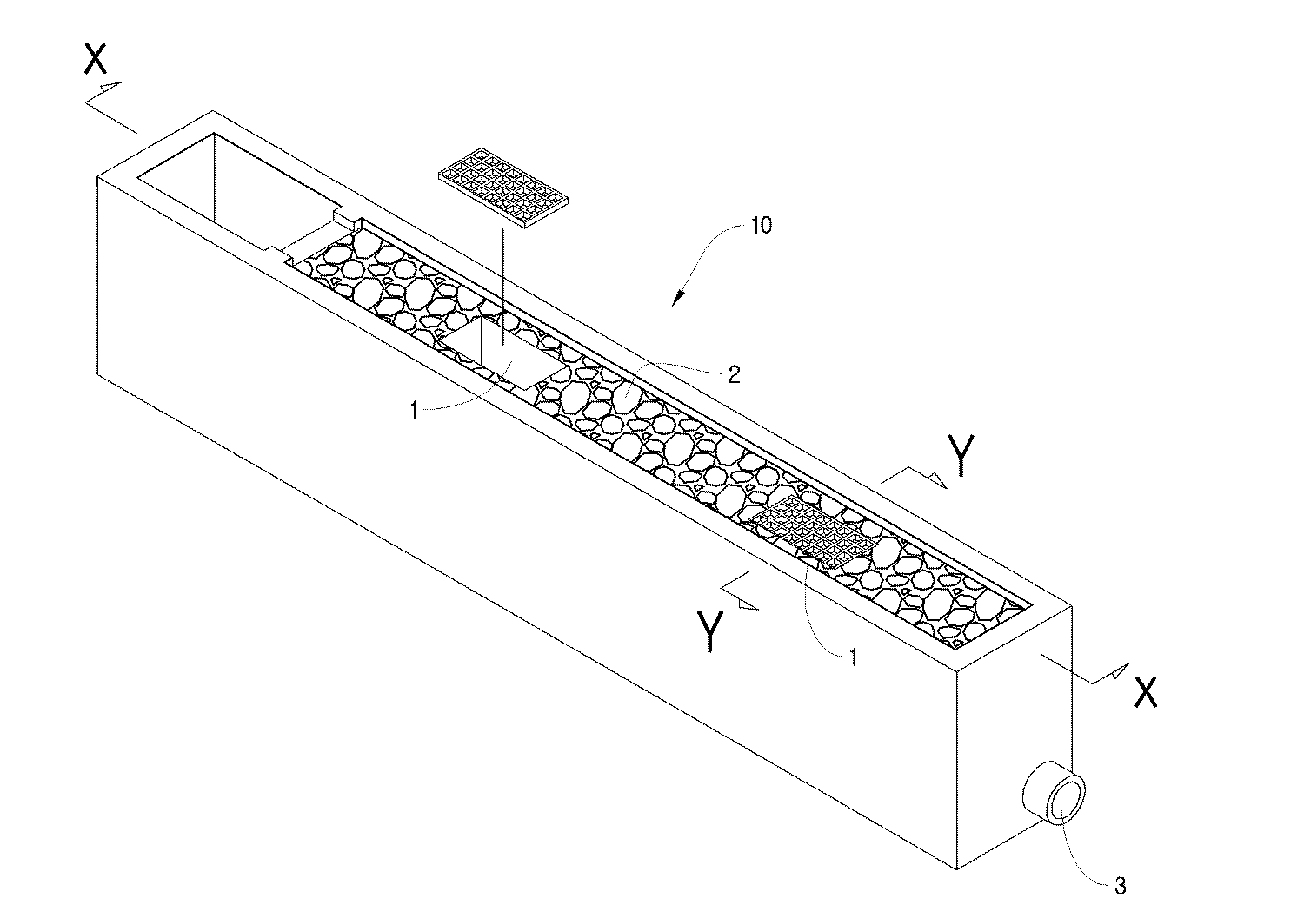
도 1은 본원발명의 제1 실시 예인 '함침형 침투도랑'의 시공 상태도를 개념적으로 보인 도면이다.
도 2는 도 1의 X-X의 단면을 개념적으로 도시한 것이고, 도 3은 도 1의 Y-Y의 단면을 보인 것으로 제1 실시 예가 주차장에 시공된 예를 보인 것이다.
도 4는 본원발명의 제2 실시 예인 '월류 유출형 침투도랑'의 평면을 보인 도면이다.
도 5는 도 4의 A-A 단면을 보인 도면이다.
도 6 내지 도 8은 본원발명의 제2 실시 예의 전처리조를 보인 것으로, 도 6은 도 4의 B-B 단면도, 도 7은 도 4의 C-C 단면도, 도 8은 도 4의 D-D 단면도이다.
도 9는 본원발명의 제2 실시 예인 침투도랑의 단면을 보인 것으로, 도 4의 E-E 단면도이다.
도 10은 본원발명의 제2 실시 예인 침투도랑에 형성된 관측정을 보인 개념도이다.
도 11은 본원발명의 제2 실시 예인 월류 유출형 침투도랑의 유출수로를 보인 것으로 그 단면도이다.1 is a view conceptually showing a construction state of 'impregnation-type penetration ditch' according to a first embodiment of the present invention.
FIG. 2 conceptually shows a cross section taken along the line XX in FIG. 1, and FIG. 3 shows a cross section taken along line YY in FIG. 1, showing an example in which the first embodiment is constructed in a parking lot.
FIG. 4 is a plan view of a 'overflow type outflow ditch' according to a second embodiment of the present invention.
5 is a cross-sectional view taken along line AA of FIG.
6 to 8 show the pretreatment tank of the second embodiment of the present invention. FIG. 6 is a sectional view taken along the line BB of FIG. 4, FIG. 7 is a sectional view taken along the line CC of FIG.
Fig. 9 is a cross-sectional view of a penetration trench according to a second embodiment of the present invention, which is a sectional view taken along the line EE of Fig.
FIG. 10 is a conceptual view showing an observation port formed in an infiltration trench according to a second embodiment of the present invention.
FIG. 11 is a cross-sectional view showing a runoff path of a overflow type infiltration trench according to a second embodiment of the present invention.
이하, 본원발명의 일 실시 예를 첨부도면을 참조하여 상세히 설명한다. 본원발명은 이하에서 개시되는 일 실시 예에 한정되는 것이 아니라 서로 다른 다양한 형태로 구현될 수 있으며, 단지 본 실시 예는 본원발명의 개시가 완전하도록 하며 통상의 지식을 가진 자에게 발명의 범주를 완전하게 알려주기 위하여 제공되는 것이다.Hereinafter, one embodiment of the present invention will be described in detail with reference to the accompanying drawings. It is to be understood that both the foregoing general description and the following detailed description are exemplary and explanatory and are not to be construed as limiting the invention to the precise form disclosed. It is provided to let you know.
도 1은 본원발명의 제1 실시 예인 '함침형 침투도랑'의 시공 상태도를 개념적으로 보인 도면이다. 본원발명은 기존에 설치되는 빗물받이(1)를 침투도랑(10)의 내부에 함침(含浸)시키는 것을 특징으로 한다. 본 명세서에서 함침이란 용어는 내부에 위치시킨다는 취지로 사용되었다.1 is a view conceptually showing a construction state of 'impregnation-type penetration ditch' according to a first embodiment of the present invention. The present invention is characterized by impregnating (impregnating) the existing rainwater collector 1 into the
강우초기 우수는 상기 침투도랑(10)으로 전량 유입되어 상기 침투도랑(10)에 충진된 여재층(도면부호 2; 본 명세서에서 각종 여재와 쇄석층을 포함하는 용어로 사용)을 통과하며 오염물질이 처리된 후 하부로 침투한다. 하부 지반으로의 침투는 시설의 하부에 형성된 다수의 침투공(4)에 의한다. 강우강도가 세지거나 하부 지반 공극층이 포화되어 침투가 더 이상 일어나지 않을 경우(침투도랑 용량은 초기우수가 모두 배제될 만큼으로 산정) 또는 집중호우가 내릴 경우에는 상기 침투도랑(10) 내부에 함침된 상기 빗물받이(1)로 신속하게 배제되도록 하여 홍수 또는 침수를 배제한다. 상기 빗물받이(1)는 배수관로(3)와 연결되어 신속하게 초과 유입된 처리대상수를 배제한다. 강우종료 후에는 침투도랑에 저류되었던 물은 서서히 상기 여재층(2)에서 여과 후 토양층으로 침투되어 초기상태로 돌아오게 된다.In the initial stage of the rainfall, all the water is introduced into the
바람직하게는 상기 침투도랑(10)은 1% 내지 3% 기울기(경사 또는 구배)를 두며 그 한쪽에는 집수정을 두어 도랑내부의 물이 집수될 수 있도록 하고, 기존 우수배제시스템에 연결하여 잔류수가 완전 배제될 수 있도록 한다. 또한 관측정(지하수 오염을 감시하기 위해 파놓은 샘.)을 두어 모니터링에 활용하는 것이 바람직하다. 함침형 침투도랑의 주요제거기작은 물순환기능(여과 후 침투, 인접된 녹지가 있을 경우 증산), 지하수 함양 및 우수배제 기능 등이다. Preferably, the
도 2는 도 1의 X-X의 단면을 개념적으로 도시한 것이고, 도 3은 도 1의 Y-Y의 단면을 보인 것으로 제1 실시 예가 주차장에 시공된 예를 보인 것이다. 도 2와 도 3에 도시된 화살표와 같이 초과로 유입되는 처리대상수는 상기 침투도랑(10)의 내측에 설치된 상기 빗물받이(1)로 유입되고, 배수관로(3)를 경유하여 신속하게 배출된다. 바람직하게는 상기 빗물받이(1)의 높이는 상기 여재층(2)의 높이보다는 높고 상기 침투도랑의 외부벽보다는 낮게 형성되는 것이 바람직하다(미도시). 초기 유입수는 상기 빗물받이(1)로 유입되지 않도록 하고, 많은 양의 유입수가 있는 경우 상기 침투도랑의 외부벽을 넘어 범람하기 전에 상기 빗물받이(1)로 신속하게 배출하기 위함이다.FIG. 2 conceptually shows a cross section taken along a line X-X in FIG. 1, and FIG. 3 shows a cross section taken along the line Y-Y in FIG. 1, showing an example in which the first embodiment is constructed in a parking lot. As shown by the arrows in FIG. 2 and FIG. 3, the water to be treated excessively flows into the rainwater receiver 1 provided inside the
도 4는 본원발명의 제2 실시 예인 '월류 유출형 침투도랑'의 평면을 보인 도면이다. 본 실시 예인 월류 유출형 침투도랑은 침투도랑의 전단에 전처리조(20)가 추가되었고, 후단에는 유출수로(30)가 형성되어 상기 침투도랑(10)을 경과한 강우가 연결배수로로 유출되어 배수된다.FIG. 4 is a plan view of a 'overflow type outflow ditch' according to a second embodiment of the present invention. In the overflow type infiltration trench according to the present embodiment, a
도 5는 도 4의 A-A 단면을 보인 도면이다. 상기 전처리조(20)로 최초 유입된 처리대상수는 상기 전처리조(20)에서 상기 침투도랑(10)으로 처리대상수가 유입되기 전에 1차적으로 처리 과정을 거친다. 침사지와 같이 수중에 포함되는 모래나 흙 등을 비중차를 이용하여 침강 분리하거나, 비중이 작고 비교적 부피가 큰 부유물들을 걸러낼 수도 있다. 도면에 도시하지 않았지만 협잡물 거름체나 스크린을 구비하여 처리대상수에 혼재하는 협잡물을 여과조에 유입되기 전에 미리 걸러냄으로써 침투도랑의 성능을 향상시키고 유출수의 수질을 향상시킬 수도 있다. 이와 같이 상기 전처리조(20)는 침투도랑의 부하를 낮추기 위한 것이며, 이를 통하여 전체적인 유지관리의 효율을 높일 수 있다. 상술한 바와 같이 침사지, 각종 스크린 또는 협잡물 거름체 등을 상기 전처리조에 배치할 수 있으며, 본원발명의 기술적 사상은 이와 같은 다양한 전처리조를 모두 포섭하는 것이다. 이와 같이 다양한 전처리조를 경과하여 어느 정도 협잡물이 제거된 처리대상수는 침투도랑 유입 월류부(10a)를 월류하여 상기 침투도랑(20)으로 유입된다. 상기 침투도랑(10)에는 관측정(15)이 구비되어 있다. 5 is a cross-sectional view taken along the line A-A in Fig. The water to be treated initially introduced into the
도 6 내지 도 8은 본원발명의 제2 실시 예의 전처리조를 보인 것으로, 도 6은 도 4의 B-B 단면도, 도 7은 도 4의 C-C 단면도, 도 8은 도 4의 D-D 단면도이다. 상기 전처리조로 유입되는 유입수는 상기 전처리조에 형성되는 전처리조 유입부(20a)를 통한다. 본 실시 예의 경우 측구인 유입수로를 통하여 유입되는 경우에 대응한 전처리조 유입부(20a)가 형성되어 있다. 상기 전처리조 유입부(20a)를 통하여 유입된 처리대상수는 상술한 바와 같이 상기 전처리조(20)에서 1차적으로 처리된 후 상기 침투도랑 유입 월류부(10a)를 넘어서 상기 침투도랑(20)으로 유입된다. 비가 오지 않는 기간에 상기 전처리조(20)에 남는 정체수는 상기 전처리조(20)의 하부에 형성되어 상기 침투도랑(10)으로 통하는 정체수 유출구(22)를 통하여 상기 침투도랑(10)으로 유입되어 하부 지반으로 침투된다. 상기 정체수 유출구(22)가 상기 전처리조(20)에 침강된 이물질에 의하여 폐색되는 것을 방지하고, 상기 정체수를 여과하여 상기 침투도랑(10)을 경유한 후 하부 지반으로 침투할 수 있도록 다음 위하여 상기 정체수 유출구(22)에 대응하여 이를 덮도록 상기 전처리조(20)의 내부에 배수용 필터섬유로 만든 모래팩(21)이 위치한다.6 to 8 show a pretreatment tank according to a second embodiment of the present invention. Fig. 6 is a sectional view taken along the line B-B in Fig. 4, Fig. 7 is a sectional view taken on line C-C in Fig. 4, and Fig. 8 is a sectional view taken on line D-D in Fig. The inflow water flowing into the pretreatment tank is passed through a pretreatment
도 9는 본원발명의 제2 실시 예인 침투도랑의 단면을 보인 것으로, 도 4의 E-E 단면도이다. 상기 침투도랑(10)의 최상단 양측에는 범람방지턱(13)이 형성되어 있다. 이는 집중 강우 시나 우기 시에 처리 용량을 초과하는 처리대상수의 유입 시에 시설 외측으로 처리대상수가 범람하지 않도록 하기 위한 것이다. 본 실시 예의 경우 터파기 후 측경사는 1:0.3으로 하였고, 최하층에는 0.1 내지 10mm의 모래 150mm가 포설된다. 상기 모래층의 상부와 상기 측경사면에는 배수용 필터섬유(14)가 배치된다. 상기 최하층 상부 배수용 필터섬유 위에 40mm 내지 60mm의 자갈이 포설되어 중간층을 형성한다. 상기 중간층의 깊이는 설계 용량에 따라 적절하게 정할 수 있다. 상기 중간층 상부에 다시 배수용 필터섬유를 배치하고, 그 상부에 최상층으로 20mm 내지 30mm의 잔자갈이 150mm 포설된다. 이와 같은 침투도랑 내의 여재층은 오염물질을 제거할 수 있는 기능이 있는 다른 구성들로 층을 형성할 수 있다. 침투도랑의 하부폭은 시공상 2.0m 이내가 바람직하며, 침투도랑의 깊이는 시공상 1.8m 이내가 바람직하다. 다만, 본원발명의 기술적 사상은 상술한 여재층의 종류나 깊이에 의하여 제한되지 않는다.9 is a cross-sectional view of a penetration trench according to a second embodiment of the present invention, which is a sectional view taken along line E-E of Fig. On both sides of the uppermost end of the infiltration ditch (10), a flood prevention tuck (13) is formed. This is to prevent the number of objects to be treated from being overflowed to the outside of the facility when the water to be treated exceeds the treatment capacity during heavy rainfall or rainy season. In this embodiment, the slope after the trench is 1: 0.3, and the lowest layer is sanded with 150 mm of sand of 0.1 to 10 mm. Draining filter fibers (14) are disposed on the upper and lower slopes of the sand layer. Gravels of 40 mm to 60 mm are laid on the lowermost top drainage filter fiber to form an intermediate layer. The depth of the intermediate layer can be appropriately determined according to the design capacity. Draining filter fibers are disposed again on the upper part of the intermediate layer, and 150 mm of gravels of 20 mm to 30 mm are laid on the upper part thereof. Such a media layer in the infiltration trench can form a layer with other structures capable of removing contaminants. The bottom width of the infiltration trench is preferably within 2.0 m on the construction site, and the infiltration depth should preferably be within 1.8 m on the construction side. However, the technical idea of the present invention is not limited by the type and depth of the above-mentioned filter medium layer.
한편, 이미 설명한 함침형 침투도랑이 본 실시 예에도 적용된다. 도 4 및 도 5에 도시된 바와 같이 함침된 빗물받이(1)는 유량이 많을 때 바이패스되도록 하는 기능을 한다. 바람직하게는 상기 빗물받이(1)의 높이는 상기 여재층의 높이보다는 높고 상기 침투도랑의 범람방지턱(13)보다는 낮게 형성되는 것이 바람직하다(미도시). 초기 유입수는 상기 빗물받이(1)로 유입되지 않도록 하고, 많은 양의 유입수가 있는 경우 상기 침투도랑의 범람방지턱(13)을 넘어 범람하기 전에 상기 빗물받이(1)와 상기 빗물받이(1)에 연결된 배수관로로 신속하게 배출하기 위함이다.On the other hand, the above-described impregnated infiltration ditch is also applied to this embodiment. As shown in FIGS. 4 and 5, the rainwater collector 1 impregnated therein functions to be bypassed when the flow rate is large. Preferably, the height of the rainwater receiver 1 is higher than the height of the filter material layer and lower than the
도 10은 본원발명의 제2 실시 예인 침투도랑에 형성된 관측정을 보인 개념도이다. 상기 관측정(15)은 아래가 밀폐된 유공관(15a)과 상기 유공관(15a)을 개폐하는 마개(15b)로 이루어져 있다. 상기 유공관은 바람직하게는 직경이 150mm인 HDPE관으로 형성할 수 있다. 본 실시 예의 경우 상기 관측정 유공관 설치는 15m 간격으로 하며 침투도랑 연장이 15m 미만일 때는 1개소를 설치한다.FIG. 10 is a conceptual view showing an observation port formed in an infiltration trench according to a second embodiment of the present invention. The
도 11은 본원발명의 제2 실시 예인 월류 유출형 침투도랑의 유출수로를 보인 것으로 그 단면도이다. 유출수로(30)의 경우에도 상기 침투도랑(10)과 마찬가지로 범람방지턱(13)이 형성되어 있다. 상기 유출수로(30)는 연결배수로로 흘러갈 수 있도록 조성하며, 바닥에 잔디를 식재할 수도 있다.FIG. 11 is a cross-sectional view showing a runoff path of a overflow type infiltration trench according to a second embodiment of the present invention. In the case of the
상술한 바와 같이 본원발명을 특정한 실시 예를 들어 설명하였으나, 본원발명은 이에 한정하는 것은 아니다. 본원발명의 기술적 사상의 범주 내에서는 얼마든지 수정 및 변형 실시가 가능함은 물론이다. Although the present invention has been described with reference to specific embodiments as described above, the present invention is not limited thereto. It will be understood by those skilled in the art that various changes and modifications may be made without departing from the scope of the present invention.
1: 빗물받이
2: 여재층
3: 배수관로
4: 침투공
10: 침투도랑
10a: 침투도랑 유입 월류부
13: 범람방지턱
14: 배수용 필터섬유
15: 관측정
15a: 유공관
15b: 마개
20: 전처리조
20a: 전처리조 유입부
21: 모래팩
22: 정체수 유출구
30: 유출수로1: Rainwater catcher
2:
3: By drain pipe
4: infiltration ball
10: penetration ditch
10a: infiltration ditch inflow section
13: Flooding bumps
14: Drainage filter fiber
15: Observation
15a:
15b: Plug
20: Pretreatment tank
20a: Pretreatment tank inflow section
21: Sand Pack
22: Stagnant water outlet
30: Runoff water
Claims (6)
상기 침투도랑은 상기 전처리조로부터 처리대상수가 유입되고,
집중 강우 시에는 유입되는 처리대상수가 상기 침투도랑을 월류하여 상기 침투도랑의 후단에 형성된 유출수로로 배출되는 월류 유출형 침투도랑이고,
상기 월류 유출형 침투도랑은 여재 또는 쇄석을 포함하는 여재층을 포함하고 유입되는 처리대상수를 하부 지반으로 침투시키는 침투도랑으로서,
상기 침투도랑의 하부에는 다수의 침투공이 형성되어 처리수를 하부 지반으로 침투시키고,
상기 침투도랑은 집중 강우 시 처리대상수를 배수관로로 배출시키며,
상기 침투도랑에는 집중 강우 시에 유입수가 범람하는 것을 방지하고 강우 중기 이후의 수질이 양호한 빗물은 별도의 처리 없이 신속하게 배제하기 위한 함침형 배출 수단을 더 포함하되,
상기 함침형 배출 수단은 유량이 많을 때 과대 유입수가 바이패스되도록 하는 것으로서 함침형 빗물받이이고,
상기 함침형 빗물받이는 상기 침투도랑의 내측에는 설치되는 빗물받이이되, 상기 빗물받이는 상기 배수관로와 연결되어 있고,
상기 빗물받이의 높이는 상기 여재층의 높이보다는 높고 상기 침투도랑의 외부벽보다는 낮게 형성되어, 초기 유입수는 상기 빗물받이로 유입되지 않으나, 많은 양의 유입수가 있는 경우 상기 침투도랑을 월류하기 전에 상기 빗물받이로 배출되는 것을 특징으로 하는
침투도랑.
As the infiltration trench in which the pretreatment tank is provided at the front end,
Wherein the infiltration trench is formed by flowing water to be treated from the pre-
Wherein the water to be treated flows through the infiltration ditch and is discharged to an effluent path formed at a rear end of the infiltration ditch .
Wherein the overflow type infiltration ditch includes infiltration material layers including filter media or crushed stone,
A plurality of infiltration holes are formed in the lower part of the infiltration trench to infiltrate the treated water into the lower ground,
The infiltration ditch discharges water to be treated at the time of intensive rainfall to a drain pipe,
The infiltration ditch further includes an impingement type discharging means for preventing inflow water from overflowing at the time of intensive rainfall and for quickly excluding the rainwater having good water quality after the middle of the rainfall without any special treatment,
The impingement type discharging means is an impregnated rainwater trap for bypassing the excessive inflow water when the flow rate is large,
Wherein the impregnated rainwater collector is a rainwater collector installed inside the infiltration trench, the rainwater collector is connected to the water pipe,
The height of the rainwater receiver is higher than the height of the filter material layer and is lower than the outer wall of the infiltration trench so that the initial influent water does not flow into the rainwater receiver. However, if there is a large amount of influent water, And is discharged to the receiver
Penetration ditch.
지하수 오염을 감시하기 위한 관측정을 더 포함하여, 시설을 모니터링할 수 있는 것을 특징으로 하는
침투도랑.
The method according to claim 1,
Further comprising an observation for monitoring groundwater contamination, characterized in that the facility can be monitored
Penetration ditch.
상기 관측정은 아래가 밀폐된 유공관과 상기 유공관을 개폐하는 마개로 이루어진 것을 특징으로 하는
침투도랑.
3. The method of claim 2,
Wherein the observation table is formed of a closed-type porous tube and a cap for opening and closing the porous tube.
Penetration ditch.
상기 전처리조에는 정체수 유출구가 형성되되,
비가 오지 않는 기간에 상기 전처리조 내에 남는 정체수를 상기 전처리조의 하부에 형성되어 상기 침투도랑으로 통하는 상기 정체수 유출구를 통하여 상기 침투도랑으로 배출하여 하부 지반으로 침투토록 하는 것을 특징으로 하는
침투도랑.
The method according to claim 1,
The pre-treatment tank is provided with a stagnant water outlet ,
The stagnant water remaining in the pre-treatment tank during a period in which no rain is generated is formed in the lower portion of the pretreatment tank and discharged to the infiltration trough through the stagnant water outlet port through the infiltration trench to infiltrate into the lower ground.
Penetration ditch.
상기 정체수 유출구가 상기 전처리조에 침강된 이물질에 의하여 폐색되는 것을 방지하고, 상기 정체수를 여과하여 상기 침투도랑을 경유한 후 하부 지반으로 침투할 수 있도록 하기 위하여 상기 정체수 유출구에 대응하여 이를 덮도록 상기 전처리조의 내부에 배수용 필터섬유로 만든 모래팩이 위치하는 것을 특징으로 하는
침투도랑.
5. The method of claim 4,
In order to prevent the stagnant water outlet from being obstructed by the foreign matter settled in the pretreatment tank and to allow the stagnant water to permeate through the infiltration trench and permeate into the lower ground, Characterized in that a sand pack made of drainage filter fibers is placed inside the pretreatment tank
Penetration ditch.
상기 침투도랑의 최상단에는 범람방지턱이 형성되어 집중 강우 시나 우기 시에 시설 외측으로 처리대상수가 범람하지 않도록 하는 것을 특징으로 하는
침투도랑.The method according to claim 1,
And an overflow preventing jaw is formed at the uppermost end of the infiltration trench so that the number of objects to be treated is not flooded outside the facility during heavy rainfall or rainy season
Penetration ditch.
Priority Applications (1)
| Application Number | Priority Date | Filing Date | Title |
|---|---|---|---|
| KR1020160033622A KR101671768B1 (en) | 2016-03-21 | 2016-03-21 | Infiltration trench with inner inlet |
Applications Claiming Priority (1)
| Application Number | Priority Date | Filing Date | Title |
|---|---|---|---|
| KR1020160033622A KR101671768B1 (en) | 2016-03-21 | 2016-03-21 | Infiltration trench with inner inlet |
Publications (1)
| Publication Number | Publication Date |
|---|---|
| KR101671768B1 true KR101671768B1 (en) | 2016-11-03 |
Family
ID=57571393
Family Applications (1)
| Application Number | Title | Priority Date | Filing Date |
|---|---|---|---|
| KR1020160033622A Active KR101671768B1 (en) | 2016-03-21 | 2016-03-21 | Infiltration trench with inner inlet |
Country Status (1)
| Country | Link |
|---|---|
| KR (1) | KR101671768B1 (en) |
Cited By (2)
| Publication number | Priority date | Publication date | Assignee | Title |
|---|---|---|---|---|
| KR101793057B1 (en) * | 2017-04-28 | 2017-11-02 | 주식회사 엔포텍디에스 | Natural type - non point pollution reducing system |
| KR102076482B1 (en) | 2019-11-14 | 2020-02-13 | 어반엘아이디 주식회사 | Vegetation Ditch Structure Using a Boundary Block |
Citations (6)
| Publication number | Priority date | Publication date | Assignee | Title |
|---|---|---|---|---|
| KR20100018781A (en) | 2008-08-07 | 2010-02-18 | 이제수 | Process and device for forming coal fuel using dered coal and the coal fuel thereof |
| KR100958326B1 (en) * | 2009-12-11 | 2010-05-17 | (주) 한국엔피기술 | Apparatus for treatment of first flush rainfall using osmosis and vegetation |
| KR101012749B1 (en) * | 2008-05-30 | 2011-02-10 | (주)비포엔지니어링 | Open Rainwater Treatment Unit |
| KR101080636B1 (en) * | 2008-12-15 | 2011-11-08 | 한국건설기술연구원 | System for decreasing nonpoint pollution source |
| KR20110138051A (en) | 2010-06-18 | 2011-12-26 | 씨앤지환경기술 (주) | Urban non-point pollutant treatment device using ecological trench |
| KR101329767B1 (en) * | 2013-05-16 | 2013-11-15 | 조국희 | Vegetation type rainwater management apparatus for filtering of nonpoint pollution |
-
2016
- 2016-03-21 KR KR1020160033622A patent/KR101671768B1/en active Active
Patent Citations (6)
| Publication number | Priority date | Publication date | Assignee | Title |
|---|---|---|---|---|
| KR101012749B1 (en) * | 2008-05-30 | 2011-02-10 | (주)비포엔지니어링 | Open Rainwater Treatment Unit |
| KR20100018781A (en) | 2008-08-07 | 2010-02-18 | 이제수 | Process and device for forming coal fuel using dered coal and the coal fuel thereof |
| KR101080636B1 (en) * | 2008-12-15 | 2011-11-08 | 한국건설기술연구원 | System for decreasing nonpoint pollution source |
| KR100958326B1 (en) * | 2009-12-11 | 2010-05-17 | (주) 한국엔피기술 | Apparatus for treatment of first flush rainfall using osmosis and vegetation |
| KR20110138051A (en) | 2010-06-18 | 2011-12-26 | 씨앤지환경기술 (주) | Urban non-point pollutant treatment device using ecological trench |
| KR101329767B1 (en) * | 2013-05-16 | 2013-11-15 | 조국희 | Vegetation type rainwater management apparatus for filtering of nonpoint pollution |
Cited By (2)
| Publication number | Priority date | Publication date | Assignee | Title |
|---|---|---|---|---|
| KR101793057B1 (en) * | 2017-04-28 | 2017-11-02 | 주식회사 엔포텍디에스 | Natural type - non point pollution reducing system |
| KR102076482B1 (en) | 2019-11-14 | 2020-02-13 | 어반엘아이디 주식회사 | Vegetation Ditch Structure Using a Boundary Block |
Similar Documents
| Publication | Publication Date | Title |
|---|---|---|
| KR100952192B1 (en) | Water pocket well for infiltrating a rainwater | |
| KR101703319B1 (en) | Rainwater permeate retention system | |
| KR102079736B1 (en) | Urban waterway system and construction method thereof | |
| KR100597203B1 (en) | Excellent receiving system for easy removal of foreign substances | |
| JP5346731B2 (en) | Rainwater penetration facilities | |
| KR100977882B1 (en) | Infiltration trench having natural water circulation and make better use of a spaceh the use of effective materials | |
| CN101624839B (en) | A Method for Comprehensively Removing Water from Underpass Roads by Filtering Infiltration Tanks | |
| KR20080101132A (en) | Rainforest reservoir for the green zone | |
| JP4445168B2 (en) | Rainwater infiltration system | |
| KR101510615B1 (en) | Penetration type rainwater storage tank and construction method of the same | |
| KR101639377B1 (en) | Rainwater storage structure of Low Impact Development | |
| JP5866221B2 (en) | Rainwater treatment facility | |
| KR102076482B1 (en) | Vegetation Ditch Structure Using a Boundary Block | |
| JPH05132993A (en) | Rainwater filter and maintaining method for its device and rainwater filtering method and its controlling equipment | |
| JP2008156974A (en) | Rainwater treating structure and rainwater treating method | |
| JP4511077B2 (en) | Rainwater drainage treatment system | |
| JP6371625B2 (en) | Rainwater storage and penetration facility | |
| KR101095322B1 (en) | Penetration trench with natural water circulation and nonpoint pollution reduction | |
| KR102377744B1 (en) | Plant box with LID infiltration ditch | |
| KR200407745Y1 (en) | Rainwater treatment system | |
| KR101792845B1 (en) | Non-point pollution treatment lid facility using garden near river stream | |
| KR101111185B1 (en) | Boundary Initial Rainfall Purification Block | |
| KR101674110B1 (en) | Infiltration trench with surface pan for pretreatment | |
| KR100714315B1 (en) | Infiltration and Reservoir System | |
| KR101055652B1 (en) | Penetration trench for natural water circulation and efficient use of media |
Legal Events
| Date | Code | Title | Description |
|---|---|---|---|
| A201 | Request for examination | ||
| PA0109 | Patent application |
St.27 status event code: A-0-1-A10-A12-nap-PA0109 |
|
| PA0201 | Request for examination |
St.27 status event code: A-1-2-D10-D11-exm-PA0201 |
|
| A302 | Request for accelerated examination | ||
| PA0302 | Request for accelerated examination |
St.27 status event code: A-1-2-D10-D17-exm-PA0302 St.27 status event code: A-1-2-D10-D16-exm-PA0302 |
|
| D13-X000 | Search requested |
St.27 status event code: A-1-2-D10-D13-srh-X000 |
|
| D14-X000 | Search report completed |
St.27 status event code: A-1-2-D10-D14-srh-X000 |
|
| E902 | Notification of reason for refusal | ||
| PE0902 | Notice of grounds for rejection |
St.27 status event code: A-1-2-D10-D21-exm-PE0902 |
|
| P11-X000 | Amendment of application requested |
St.27 status event code: A-2-2-P10-P11-nap-X000 |
|
| P13-X000 | Application amended |
St.27 status event code: A-2-2-P10-P13-nap-X000 |
|
| R18-X000 | Changes to party contact information recorded |
St.27 status event code: A-3-3-R10-R18-oth-X000 |
|
| E701 | Decision to grant or registration of patent right | ||
| PE0701 | Decision of registration |
St.27 status event code: A-1-2-D10-D22-exm-PE0701 |
|
| GRNT | Written decision to grant | ||
| PR0701 | Registration of establishment |
St.27 status event code: A-2-4-F10-F11-exm-PR0701 |
|
| PR1002 | Payment of registration fee |
St.27 status event code: A-2-2-U10-U11-oth-PR1002 Fee payment year number: 1 |
|
| PG1601 | Publication of registration |
St.27 status event code: A-4-4-Q10-Q13-nap-PG1601 |
|
| FPAY | Annual fee payment |
Payment date: 20191028 Year of fee payment: 4 |
|
| PR1001 | Payment of annual fee |
St.27 status event code: A-4-4-U10-U11-oth-PR1001 Fee payment year number: 4 |
|
| P14-X000 | Amendment of ip right document requested |
St.27 status event code: A-5-5-P10-P14-nap-X000 |
|
| P14-X000 | Amendment of ip right document requested |
St.27 status event code: A-5-5-P10-P14-nap-X000 |
|
| FPAY | Annual fee payment |
Payment date: 20201026 Year of fee payment: 5 |
|
| PR1001 | Payment of annual fee |
St.27 status event code: A-4-4-U10-U11-oth-PR1001 Fee payment year number: 5 |
|
| R18-X000 | Changes to party contact information recorded |
St.27 status event code: A-5-5-R10-R18-oth-X000 |
|
| FPAY | Annual fee payment |
Payment date: 20220125 Year of fee payment: 6 |
|
| PR1001 | Payment of annual fee |
St.27 status event code: A-4-4-U10-U11-oth-PR1001 Fee payment year number: 6 |
|
| R18-X000 | Changes to party contact information recorded |
St.27 status event code: A-5-5-R10-R18-oth-X000 |
|
| PR1001 | Payment of annual fee |
St.27 status event code: A-4-4-U10-U11-oth-PR1001 Fee payment year number: 7 |
|
| R18-X000 | Changes to party contact information recorded |
St.27 status event code: A-5-5-R10-R18-oth-X000 |
|
| PR1001 | Payment of annual fee |
St.27 status event code: A-4-4-U10-U11-oth-PR1001 Fee payment year number: 8 |
|
| PR1001 | Payment of annual fee |
St.27 status event code: A-4-4-U10-U11-oth-PR1001 Fee payment year number: 9 |
|
| R18-X000 | Changes to party contact information recorded |
St.27 status event code: A-5-5-R10-R18-oth-X000 |
|
| R18-X000 | Changes to party contact information recorded |
St.27 status event code: A-5-5-R10-R18-oth-X000 |
|
| PR1001 | Payment of annual fee |
St.27 status event code: A-4-4-U10-U11-oth-PR1001 Fee payment year number: 10 |
|
| U11 | Full renewal or maintenance fee paid |
Free format text: ST27 STATUS EVENT CODE: A-4-4-U10-U11-OTH-PR1001 (AS PROVIDED BY THE NATIONAL OFFICE) Year of fee payment: 10 |