KR20180063211A - LIDAR system with reflected signal strength measurement - Google Patents
LIDAR system with reflected signal strength measurement Download PDFInfo
- Publication number
- KR20180063211A KR20180063211A KR1020187012214A KR20187012214A KR20180063211A KR 20180063211 A KR20180063211 A KR 20180063211A KR 1020187012214 A KR1020187012214 A KR 1020187012214A KR 20187012214 A KR20187012214 A KR 20187012214A KR 20180063211 A KR20180063211 A KR 20180063211A
- Authority
- KR
- South Korea
- Prior art keywords
- time data
- analog signal
- lidar system
- reflected
- pulse
- Prior art date
Links
- 238000005259 measurement Methods 0.000 title description 12
- 238000000034 method Methods 0.000 claims abstract description 66
- 230000003287 optical effect Effects 0.000 claims abstract description 48
- 230000008569 process Effects 0.000 claims abstract description 21
- 230000004044 response Effects 0.000 claims abstract description 20
- 238000005070 sampling Methods 0.000 claims description 15
- 238000012545 processing Methods 0.000 claims description 13
- 238000001514 detection method Methods 0.000 claims description 7
- 238000002310 reflectometry Methods 0.000 claims description 6
- 238000010586 diagram Methods 0.000 description 13
- 230000006870 function Effects 0.000 description 9
- 230000003416 augmentation Effects 0.000 description 4
- 238000013461 design Methods 0.000 description 4
- 230000003190 augmentative effect Effects 0.000 description 3
- 238000004891 communication Methods 0.000 description 3
- 208000034188 Stiff person spectrum disease Diseases 0.000 description 2
- 230000008901 benefit Effects 0.000 description 2
- 230000005540 biological transmission Effects 0.000 description 2
- 230000009977 dual effect Effects 0.000 description 2
- 238000005516 engineering process Methods 0.000 description 2
- 208000012112 ischiocoxopodopatellar syndrome Diseases 0.000 description 2
- 230000007774 longterm Effects 0.000 description 2
- 238000012805 post-processing Methods 0.000 description 2
- XUIMIQQOPSSXEZ-UHFFFAOYSA-N Silicon Chemical compound [Si] XUIMIQQOPSSXEZ-UHFFFAOYSA-N 0.000 description 1
- 229920010524 Syndiotactic polystyrene Polymers 0.000 description 1
- 238000004458 analytical method Methods 0.000 description 1
- 238000003491 array Methods 0.000 description 1
- 239000003990 capacitor Substances 0.000 description 1
- 230000001413 cellular effect Effects 0.000 description 1
- 230000001427 coherent effect Effects 0.000 description 1
- 238000004590 computer program Methods 0.000 description 1
- 238000012937 correction Methods 0.000 description 1
- 230000008878 coupling Effects 0.000 description 1
- 238000010168 coupling process Methods 0.000 description 1
- 238000005859 coupling reaction Methods 0.000 description 1
- 230000007423 decrease Effects 0.000 description 1
- 238000002592 echocardiography Methods 0.000 description 1
- 230000000694 effects Effects 0.000 description 1
- 230000005670 electromagnetic radiation Effects 0.000 description 1
- 238000010304 firing Methods 0.000 description 1
- 238000010295 mobile communication Methods 0.000 description 1
- 238000012986 modification Methods 0.000 description 1
- 230000004048 modification Effects 0.000 description 1
- 239000002245 particle Substances 0.000 description 1
- 230000003252 repetitive effect Effects 0.000 description 1
- 229910052710 silicon Inorganic materials 0.000 description 1
- 239000010703 silicon Substances 0.000 description 1
- 239000007787 solid Substances 0.000 description 1
- 238000002490 spark plasma sintering Methods 0.000 description 1
- 230000001052 transient effect Effects 0.000 description 1
- 230000001960 triggered effect Effects 0.000 description 1
Images


Classifications
-
- G—PHYSICS
- G01—MEASURING; TESTING
- G01S—RADIO DIRECTION-FINDING; RADIO NAVIGATION; DETERMINING DISTANCE OR VELOCITY BY USE OF RADIO WAVES; LOCATING OR PRESENCE-DETECTING BY USE OF THE REFLECTION OR RERADIATION OF RADIO WAVES; ANALOGOUS ARRANGEMENTS USING OTHER WAVES
- G01S7/00—Details of systems according to groups G01S13/00, G01S15/00, G01S17/00
- G01S7/48—Details of systems according to groups G01S13/00, G01S15/00, G01S17/00 of systems according to group G01S17/00
- G01S7/483—Details of pulse systems
- G01S7/486—Receivers
- G01S7/4861—Circuits for detection, sampling, integration or read-out
-
- G—PHYSICS
- G01—MEASURING; TESTING
- G01S—RADIO DIRECTION-FINDING; RADIO NAVIGATION; DETERMINING DISTANCE OR VELOCITY BY USE OF RADIO WAVES; LOCATING OR PRESENCE-DETECTING BY USE OF THE REFLECTION OR RERADIATION OF RADIO WAVES; ANALOGOUS ARRANGEMENTS USING OTHER WAVES
- G01S17/00—Systems using the reflection or reradiation of electromagnetic waves other than radio waves, e.g. lidar systems
- G01S17/02—Systems using the reflection of electromagnetic waves other than radio waves
- G01S17/06—Systems determining position data of a target
- G01S17/08—Systems determining position data of a target for measuring distance only
- G01S17/10—Systems determining position data of a target for measuring distance only using transmission of interrupted, pulse-modulated waves
-
- G01S17/105—
-
- G—PHYSICS
- G01—MEASURING; TESTING
- G01S—RADIO DIRECTION-FINDING; RADIO NAVIGATION; DETERMINING DISTANCE OR VELOCITY BY USE OF RADIO WAVES; LOCATING OR PRESENCE-DETECTING BY USE OF THE REFLECTION OR RERADIATION OF RADIO WAVES; ANALOGOUS ARRANGEMENTS USING OTHER WAVES
- G01S17/00—Systems using the reflection or reradiation of electromagnetic waves other than radio waves, e.g. lidar systems
- G01S17/02—Systems using the reflection of electromagnetic waves other than radio waves
- G01S17/06—Systems determining position data of a target
- G01S17/08—Systems determining position data of a target for measuring distance only
- G01S17/10—Systems determining position data of a target for measuring distance only using transmission of interrupted, pulse-modulated waves
- G01S17/14—Systems determining position data of a target for measuring distance only using transmission of interrupted, pulse-modulated waves wherein a voltage or current pulse is initiated and terminated in accordance with the pulse transmission and echo reception respectively, e.g. using counters
-
- G—PHYSICS
- G01—MEASURING; TESTING
- G01S—RADIO DIRECTION-FINDING; RADIO NAVIGATION; DETERMINING DISTANCE OR VELOCITY BY USE OF RADIO WAVES; LOCATING OR PRESENCE-DETECTING BY USE OF THE REFLECTION OR RERADIATION OF RADIO WAVES; ANALOGOUS ARRANGEMENTS USING OTHER WAVES
- G01S7/00—Details of systems according to groups G01S13/00, G01S15/00, G01S17/00
- G01S7/48—Details of systems according to groups G01S13/00, G01S15/00, G01S17/00 of systems according to group G01S17/00
- G01S7/483—Details of pulse systems
- G01S7/486—Receivers
- G01S7/4865—Time delay measurement, e.g. time-of-flight measurement, time of arrival measurement or determining the exact position of a peak
-
- G—PHYSICS
- G01—MEASURING; TESTING
- G01S—RADIO DIRECTION-FINDING; RADIO NAVIGATION; DETERMINING DISTANCE OR VELOCITY BY USE OF RADIO WAVES; LOCATING OR PRESENCE-DETECTING BY USE OF THE REFLECTION OR RERADIATION OF RADIO WAVES; ANALOGOUS ARRANGEMENTS USING OTHER WAVES
- G01S7/00—Details of systems according to groups G01S13/00, G01S15/00, G01S17/00
- G01S7/48—Details of systems according to groups G01S13/00, G01S15/00, G01S17/00 of systems according to group G01S17/00
- G01S7/483—Details of pulse systems
- G01S7/486—Receivers
- G01S7/4868—Controlling received signal intensity or exposure of sensor
Abstract
예시적인 LIDAR 시스템은 검출기, 증폭기, TDC(time-to-digital converter), 적분기, ADC(analog-to-digital converter) 및 프로세서를 포함한다. 검출기는 반사된 광 펄스를 수신하도록 구성되며, 여기서 반사된 광 펄스는 오브젝트로부터 반사된다. 증폭기는 반사광 펄스에 대한 응답으로 아날로그 신호를 생성하도록 검출기에 커플링된다. TDC는, 아날로그 신호에 대한 응답으로 제 1 시간 데이터 및 제 2 시간 데이터를 생성하도록 증폭기에 커플링된다. 적분기는 아날로그 신호를 적분하도록 증폭기에 커플링된다. ADC는 적분기에 커플링되어 적분기의 출력을 샘플링하고 디지털 샘플을 생성한다. 프로세서는 반사된 광 펄스의 총 반사 에너지를 추정하기 위해 제 1 시간 데이터, 제 2 시간 데이터 및 디지털 샘플을 프로세싱하도록 구성된다. Exemplary LIDAR systems include detectors, amplifiers, time-to-digital converters (TDCs), integrators, analog-to-digital converters (ADCs), and processors. The detector is configured to receive the reflected optical pulses, wherein the reflected optical pulses are reflected from the object. The amplifier is coupled to the detector to produce an analog signal in response to the reflected light pulse. The TDC is coupled to the amplifier to produce first time data and second time data in response to the analog signal. The integrator is coupled to the amplifier to integrate the analog signal. The ADC is coupled to an integrator to sample the output of the integrator and generate a digital sample. The processor is configured to process the first time data, the second time data and the digital samples to estimate the total reflected energy of the reflected optical pulses.
Description
[0001] 본 특허출원은, 2015년 9월 29일자로 출원되고 발명의 명칭이 "LIDAR SYSTEM WITH REFLECTED SIGNAL STRENGTH MEASUREMENT"인 미국 가출원 번호 제62/234,328호를 우선권으로 주장하며, 이는 본원의 양수인에게 양도되고 그 전체가 인용에 의해 명시적으로 본원에 포함된다. [0001] This patent application claims priority to U.S. Provisional Application No. 62 / 234,328, filed on September 29, 2015, entitled " LIDAR SYSTEM WITH REFLECTED SIGNAL STRENGTH MEASUREMENT ", which is assigned to the assignee of the present application, The entirety of which is expressly incorporated herein by reference.
[0002] 본 개시는 일반적으로 LIDAR(Light Detection And Ranging) 시스템들에 관한 것이다. [0002] This disclosure generally relates to Light Detection And Ranging (LIDAR) systems.
[0003] LIDAR 및/또는 LADAR(즉, Laser Detection And Ranging) 시스템들에 대해, (타이밍 정보 외에도) 반사된 신호들의 강도/에너지에 관한 정보를 추출할 수 있는 것이 유익할 수 있다. 이 정보는 스캐터(scatter)의 위치 및 반사된 광의 강도에 관한 정보를 제공함으로써 LIDAR/LADAR 데이터의 사후 프로세싱 분석의 강화를 허용할 수 있다. 예를 들어, 실제 LIDAR/LADAR 시스템들이 종종, (태양, 자동차의 하이빔(high beam)들 등으로부터의) 강한 노이즈 신호들이 있는데서 동작하기 때문에, 이 노이즈는 시스템의 수신 경로로 새어 들어갈 것이고 이 노이즈는 오브젝트 검출의 정확성 및 신뢰성에 영향을 줄 수 있다. 수신된 신호 강도의 상관은, LIDAR 시스템이 신뢰성 메트릭들(reliability metrics)을 구현하는 것을 가능하게 하는데 ― 더 강한 반사 신호들을 갖는 오브젝트들을 검출할 때, LIDAR 시스템은 더 높은 신뢰도 값을 거기에 할당하고, 이에 따라 데이터의 보다 효율적인 사후 프로세싱을 가능하게 할 수 있다. [0003] For LIDAR and / or LADAR (i.e., Laser Detection And Ranging) systems, it may be advantageous to be able to extract information about the intensity / energy of the reflected signals (in addition to the timing information). This information may allow for enhanced post processing analysis of LIDAR / LADAR data by providing information about the location of the scatter and the intensity of the reflected light. For example, since the actual LIDAR / LADAR systems often operate with strong noise signals (from the sun, high beams of automobiles, etc.), this noise will leak into the receive path of the system, It may affect the accuracy and reliability of object detection. Correlation of the received signal strength makes it possible for the LIDAR system to implement reliability metrics-when it detects objects with stronger reflected signals, the LIDAR system assigns a higher confidence value there , Thereby enabling more efficient post-processing of the data.
[0004] 하나의 LIDAR 시스템에서, LIDAR 신호 트레이스를 직접 디지털화하기 위해 고성능의 속도 및 정확도의 ADC(analog-to-digital converter)가 사용된다. 이러한 고성능 ADC들을 이용하는 이점은, 이들이 수신된 신호 강도의 직접 측정 및 다중 반사들 사이의 양호한 분해능을 허용한다는 것이다. 그러나 이러한 ADC들에 대한 요건들은 매우 높다. 이러한 요건들을 충족시킬 수 있는 ADC들은 비용이 많이 들고 많은 전력을 소비하는 경향이 있다. [0004] In one LIDAR system, a high-performance, speed-and-accuracy analog-to-digital converter (ADC) is used to directly digitize the LIDAR signal traces. An advantage of using these high performance ADCs is that they permit a direct measurement of the received signal strength and good resolution between multiple reflections. However, the requirements for these ADCs are very high. ADCs capable of meeting these requirements tend to be expensive and consume much power.
[0005] 다른 LIDAR 시스템들은 다중-채널 타임-투-디스턴스(Time-to-Distance)(본원에서 타임-투-디지털(time-to-distance)로서 또한 지칭됨) 변환기(Converter)(TDC)를 활용할 수 있다. TDC들은 ADC보다 훨씬 더 단순한 솔루션이고, 상대적으로 저렴하며, 동작에 많은 전력이 필요로 하지 않는다. 그러나, TDC들이 반사된 신호의 타이밍 정보를 직접 측정할 수 있지만, TDC들은 반사된 광의 전력을 추정하는데 있어 매우 부정확할 수 있다. [0005] Other LIDAR systems may utilize a multi-channel time-to-distance (also referred to herein as time-to-distance) converter (TDC) . TDCs are a much simpler solution than ADCs, are relatively inexpensive, and do not require much power to operate. However, TDCs can directly measure the timing information of the reflected signal, but TDCs can be very inaccurate in estimating the power of the reflected light.
[0006] 본 개시의 양상들은 LIDAR 시스템에서 반사된 신호 강도 측정을 보조하거나 그렇지 않으면 이를 수행하기 위한 방법, 장치, LIDAR 시스템 및 컴퓨터-판독 가능 매체를 포함한다. [0006] Aspects of the present disclosure include methods, apparatus, LIDAR systems, and computer-readable media for aiding or otherwise supporting reflected signal strength measurements in a LIDAR system.
[0007] 예를 들어, 일 양상에 따라, 예시적인 LIDAR 시스템은 검출기, 증폭기, TDC(time-to-digital converter), 적분기, ADC(analog-to-digital converter) 및 프로세서를 포함한다. 검출기는 반사된 광 펄스를 수신하도록 구성되며, 여기서 반사된 광 펄스는 오브젝트로부터 반사된다. 증폭기는 반사된 광 펄스에 대한 응답으로 아날로그 신호를 생성하도록 검출기에 커플링된다. TDC는, 아날로그 신호에 대한 응답으로 적어도 제 1 시간 데이터 및 제 2 시간 데이터를 생성하도록 증폭기에 커플링된다. 적분기는 아날로그 신호를 적분하도록 증폭기에 커플링된다. ADC는 적분기에 커플링되어 적분기의 출력을 샘플링하고 디지털 샘플을 생성한다. 프로세서는 반사된 광 펄스의 총 반사 에너지를 추정하기 위해 제 1 시간 데이터, 제 2 시간 데이터 및 디지털 샘플을 프로세싱하도록 구성된다. [0007] For example, in accordance with an aspect, an exemplary LIDAR system includes a detector, an amplifier, a time-to-digital converter (TDC), an integrator, an analog-to-digital converter (ADC) and a processor. The detector is configured to receive the reflected optical pulses, wherein the reflected optical pulses are reflected from the object. The amplifier is coupled to the detector to generate an analog signal in response to the reflected optical pulses. The TDC is coupled to the amplifier to generate at least first time data and second time data in response to the analog signal. The integrator is coupled to the amplifier to integrate the analog signal. The ADC is coupled to an integrator to sample the output of the integrator and generate a digital sample. The processor is configured to process the first time data, the second time data and the digital samples to estimate the total reflected energy of the reflected optical pulses.
[0008] 다른 양상에 따라, LIDAR 시스템과 함께 사용하기 위한 예시적인 방법은 LIDAR 시스템의 검출기에서 반사된 광 펄스를 수신하는 단계를 포함하고, 반사된 광 펄스는 오브젝트로부터 반사된다. 방법은 추가로, 반사된 광 펄스에 대한 응답으로 아날로그 신호를 생성하는 단계 ― 아날로그 신호는 반사된 광 펄스를 나타냄 ― ; 및 아날로그 신호에 대한 응답으로 TDC(time-to-digital converter)로 적어도 제 1 시간 데이터 및 제 2 시간 데이터를 생성하는 단계를 포함한다. 또한, 방법은, 아날로그 신호를 적분기로 적분하는 단계 및 적분기의 출력을 나타내는 디지털 샘플을 생성하기 위해 하나 또는 그 초과의 샘플링 시간들에 ADC(analog-to-digital converter)로 적분기의 출력을 샘플링하는 단계를 포함한다. 그 후, 제 1 시간 데이터, 제 2 시간 데이터 및 디지털 샘플은 반사된 광 펄스의 총 반사 에너지를 추정하기 위해 프로세싱된다. [0008] According to another aspect, an exemplary method for use with a LIDAR system includes receiving a reflected optical pulse at a detector of a LIDAR system, wherein the reflected optical pulse is reflected from the object. The method further includes generating an analog signal in response to the reflected optical pulse, wherein the analog signal represents a reflected optical pulse; And generating at least first time data and second time data with a time-to-digital converter (TDC) in response to the analog signal. The method also includes sampling the output of the integrator with an analog-to-digital converter (ADC) at one or more sampling times to integrate the analog signal into an integrator and generate a digital sample representative of the output of the integrator . The first time data, second time data and digital samples are then processed to estimate the total reflected energy of the reflected optical pulses.
[0009] 또 다른 양상에서, 예시적인 LIDAR 시스템은 메모리 및 메모리에 커플링되는 프로세서를 포함한다. 메모리는 프로그램 코드를 저장하도록 적응되고, 프로세서는, 프로그램 코드에 포함된 명령들에 액세스 및 실행하여, (i) LIDAR 시스템의 검출기에서 반사된 광 펄스를 수신하고 ― 반사된 광 펄스는 오브젝트로부터 반사됨 ― ; (ii) 반사된 광 펄스에 대한 응답으로 아날로그 신호를 생성하고 ― 아날로그 신호는 반사된 광 펄스를 나타냄 ― ; (iii) 아날로그 신호에 대한 응답으로 TDC(time-to-digital converter)로 적어도 제 1 시간 데이터 및 제 2 시간 데이터를 생성하고; (iv) 아날로그 신호를 적분기로 적분하고; (v) 적분기의 출력을 나타내는 디지털 샘플을 생성하기 위해 하나 또는 그 초과의 샘플링 시간들에 ADC(analog-to-digital converter)로 적분기의 출력을 샘플링하고; 그리고 (vi) 반사된 광 펄스의 총 반사 에너지를 추정하기 위해 제 1 시간 데이터, 제 2 시간 데이터 및 디지털 샘플을 프로세싱하도록 LIDAR 시스템에 지시하게 구성된다. [0009] In another aspect, an exemplary LIDAR system includes a memory and a processor coupled to the memory. The memory is adapted to store the program code, and the processor accesses and executes the instructions contained in the program code to (i) receive the reflected optical pulses at the detector of the LIDAR system, and -; (ii) generating an analog signal in response to the reflected optical pulse, the analog signal representing a reflected optical pulse; (iii) generating at least first time data and second time data with a time-to-digital converter (TDC) in response to the analog signal; (iv) integrating the analog signal with an integrator; (v) sampling the output of the integrator with an analog-to-digital converter (ADC) at one or more sampling times to produce a digital sample representative of the output of the integrator; And (vi) instructing the LIDAR system to process the first time data, the second time data and the digital samples to estimate the total reflected energy of the reflected optical pulses.
[0010] 다른 양상에서, LIDAR 시스템은, (i) LIDAR 시스템의 검출기에서 반사된 광 펄스를 수신하기 위한 수단 ― 반사된 광 펄스는 오브젝트로부터 반사됨 ― ; (ii) 반사된 광 펄스에 대한 응답으로 아날로그 신호를 생성하기 위한 수단 ― 아날로그 신호는 반사된 광 펄스를 나타냄 ― ; (iii) 아날로그 신호에 대한 응답으로 TDC(time-to-digital converter)로 적어도 제 1 시간 데이터 및 제 2 시간 데이터를 생성하기 위한 수단; (iv) 아날로그 신호를 적분하기 위한 수단; (v) 적분하기 위한 수단의 출력을 나타내는 디지털 샘플을 생성하도록 하나 또는 그 초과의 샘플링 시간들에 적분하기 위한 수단의 출력을 샘플링하기 위한 수단; 및 (vi) 반사된 광 펄스의 총 반사 에너지를 추정하기 위해 제 1 시간 데이터, 제 2 시간 데이터 및 디지털 샘플을 프로세싱하기 위한 수단을 포함한다. [0010] In another aspect, the LIDAR system comprises: (i) means for receiving reflected light pulses at a detector of a LIDAR system, wherein the reflected light pulses are reflected from the object; (ii) means for generating an analog signal in response to a reflected optical pulse, the analog signal representing a reflected optical pulse; (iii) means for generating at least first time data and second time data with a time-to-digital converter (TDC) in response to an analog signal; (iv) means for integrating an analog signal; (v) means for sampling the output of the means for integrating into one or more sampling times to produce a digital sample representative of the output of the means for integrating; And (vi) means for processing the first time data, the second time data and the digital samples to estimate the total reflected energy of the reflected optical pulses.
[0011]
첨부 도면들은, 본 발명의 실시예들의 설명을 보조하도록 제시되며, 실시예들의 제한이 아니라 그들의 예시를 위해서만 제공된다.
[0012]
도 1은 예시적인 LIDAR 시스템을 예시하는 블록도이다.
[0013]
도 2는 예시적인 LIDAR 시스템을 예시하는 블록도이다.
[0014]
도 3은 LIDAR 시스템의 예시적인 검출기를 예시하는 블록도이다.
[0015]
도 4a 내지 도 4d는 LIDAR 시스템의 다중-채널 TDC의 동작을 예시하는 타이밍도이다.
[0016]
도 5는 LIDAR 시스템의 적분기의 동작을 예시하는 타이밍도이다.
[0017]
도 6은 LIDAR 시스템에서 반사된 신호 강도 측정을 수행하는 예시적인 프로세스를 예시하는 흐름도이다.
[0018]
도 7은 LIDAR 시스템에서 사용될 수 있고 본원에서 교시된 바와 같은 반사된 신호 강도 측정을 수행하는 것을 지원하도록 구성된 컴포넌트들의 여러 샘플 양상들의 단순화된 블록도이다. BRIEF DESCRIPTION OF THE DRAWINGS [0011] The accompanying drawings are provided to aid in describing the embodiments of the invention and are provided by way of illustration only, and not limitation of the embodiments.
[0012] Figure 1 is a block diagram illustrating an exemplary LIDAR system.
[0013] FIG. 2 is a block diagram illustrating an exemplary LIDAR system.
[0014] FIG. 3 is a block diagram illustrating an exemplary detector of a LIDAR system.
[0015] Figures 4A-4D are timing diagrams illustrating operation of a multi-channel TDC in a LIDAR system.
[0016] FIG. 5 is a timing diagram illustrating the operation of the integrator of the LIDAR system.
[0017] FIG. 6 is a flow diagram illustrating an exemplary process for performing a reflected signal strength measurement in a LIDAR system.
[0018] FIG. 7 is a simplified block diagram of several sample aspects of components that may be used in a LIDAR system and configured to support performing a reflected signal strength measurement as taught herein.
[0019] 본 개시의 양상들은, 특정한 실시예들에 관한 다음의 설명 및 관련된 도면들에서 개시된다. 본 발명의 범위를 벗어나지 않으면서 대안적인 실시예들이 고안될 수 있다. 부가적으로, 본 발명의 잘-알려진 엘리먼트들은 본 발명의 관련된 세부사항들이 모호하지 않도록, 상세히 설명되지 않거나 또는 생략될 것이다. [0019] Aspects of the disclosure are set forth in the following description of specific embodiments and the associated drawings. Alternative embodiments may be devised without departing from the scope of the invention. Additionally, well-known elements of the present invention will not be described in detail or will be omitted so as not to obscure the relevant details of the present invention.
[0020] "예시적인"이란 단어는, "예, 경우 또는 예시로서 기능하는" 것을 의미하도록 본원에서 사용된다. "예시적인" 것으로서 본원에서 설명되는 어떠한 실시예도 다른 실시예들에 비해 바람직하거나 또는 유리한 것으로 해석될 필요는 없다. 유사하게, "본 발명의 실시예들"이란 용어는, 본 발명의 실시예들 전부가 논의된 특징, 이점, 또는 동작 모드를 포함하는 것을 요구하지는 않는다. [0020] The word "exemplary" is used herein to mean "serving as an example, instance, or illustration. &Quot; Any embodiment described herein as "exemplary " is not necessarily to be construed as preferred or advantageous over other embodiments. Similarly, the term " embodiments of the present invention " does not require that all of the embodiments of the present invention include the features, advantages, or modes of operation discussed.
[0021] 본원에서 사용된 용어는 특정 실시예들을 설명하려는 목적만을 위한 것이며, 본 발명의 실시예들을 제한하는 것으로 의도되지 않는다. 본원에서 사용되는 바와 같이, 맥락이 명확하게 달리 표시하지 않으면, 단수 형태들은 복수 형태들을 또한 포함하는 것으로 의도된다. 추가로, 용어들 "구비하는", "구비", "포함하는" 및/또는 "포함"이 본원에서 사용될 때, 언급된 특징들, 정수들, 단계들, 동작들, 엘리먼트들, 및/또는 컴포넌트들의 존재를 특정하지만, 하나 또는 그 초과의 다른 특징들, 정수들, 단계들, 동작들, 엘리먼트들, 컴포넌트들, 및/또는 이들의 그룹들의 존재 또는 부가를 배제하지 않는다는 것이 이해될 것이다. [0021] The terminology used herein is for the purpose of describing particular embodiments only and is not intended to limit the embodiments of the invention. As used herein, the singular forms are intended to also include the plural forms unless the context clearly dictates otherwise. Further, when used in this application, terms such as "comprising," "comprising," "including," and / or "includes," when used herein, refer to the stated features, integers, steps, operations, elements, and / It will be appreciated that while specifying the presence of components does not exclude the presence or addition of one or more other features, integers, steps, operations, elements, components, and / or groups thereof.
[0022] 추가로, 많은 실시예들은, 예를 들어, 컴퓨팅 디바이스의 엘리먼트들에 의해 수행되는 액션들의 시퀀스들의 관점들에서 설명된다. 본원에 설명된 다양한 액션들은, 특정 회로들(예를 들어, ASIC(application-specific integrated circuit)들)에 의해, 하나 또는 그 초과의 프로세서들에 의해 실행되는 프로그램 명령들에 의해, 또는 이 둘 모두의 결합에 의해 수행될 수 있다는 것이 인지될 것이다. 부가적으로, 본원에 설명된 이들 액션들의 시퀀스는, 실행 시에, 연관된 프로세서로 하여금 본원에 설명된 기능을 수행하게 하는 컴퓨터 명령들의 대응하는 세트가 저장된 임의의 형태의 컴퓨터-판독 가능 저장 매체 내에서 완전히 실현되는 것으로 고려될 수 있다. 따라서, 본 발명의 다양한 양상들은 다수의 상이한 형태들로 구현될 수 있으며, 이들 전부는 청구되는 청구 대상의 범위 내에 있는 것으로 고려된다. [0022] Additionally, many embodiments are described in terms of, for example, sequences of actions performed by elements of a computing device. The various actions described herein may be performed by specific circuits (e.g., application-specific integrated circuits (ASICs)), by program instructions executed by one or more processors, ≪ / RTI > Additionally, the sequence of these actions described herein may be implemented in any form of computer-readable storage medium having stored thereon a corresponding set of computer instructions for causing an associated processor to perform the functions described herein Can be considered to be fully realized. Accordingly, various aspects of the present invention may be embodied in a number of different forms, all of which are considered within the scope of the claimed subject matter.
[0023]
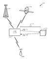
도 1은 환경(100)에서 동작하는 예시적인 LIDAR 시스템(102)을 예시하는 블록도이다. 도 1에 도시된 바와 같이, LIDAR 시스템(102)은 LIDAR 시스템(102)으로부터 오브젝트(110)까지의 거리(116)를 측정하도록 구성된다. 일 양상에서, LIDAR 시스템(102)은 ToF(Time of Flight) 방법을 활용하며, 여기서 LIDAR 시스템(102)은 레이저 펄스(112)가 환경(100)으로 전송된 시간과 반사된 펄스(114)(본원에서 에코(echo)로서 또한 지칭됨)가 LIDAR 시스템(102)에 의해 검출되는 시간 간의 시간 지연을 측정한다. 아래에서 보다 상세히 논의되는 바와 같이, LIDAR 시스템(102)은 또한 반사된 펄스(114)의 신호 강도 및/또는 오브젝트(110)의 반사도 값을 측정하도록 구성된다. [0023]
FIG. 1 is a block diagram illustrating an
[0024]
일 양상에서, LIDAR 시스템(102)은 하나 또는 그 초과의 포지셔닝 시스템들을 통해 오브젝트(110)의 스캐닝을 돕기 위해 그의 포지션/위치를 결정할 수 있다. 예를 들어, SPS(satellite positioning system)는 통상적으로 엔티티들이 송신기들로부터 수신된 신호들에 적어도 부분적으로 기초하여 지상의 또는 그 위의 엔티티들의 위치들을 결정하는 것을 가능하게 하도록 포지셔닝되는 송신기들의 시스템을 포함한다. 통상적으로, 그러한 송신기는 세팅된 수의 칩들의 반복 의사-랜덤 노이즈(PN) 코드로 마킹된 신호를 송신하며, 지상 기반 제어 스테이션들, 사용자 장비 및/또는 위성체(space vehicle)들 상에 로케이팅될 수 있다. 특정 예에서, 그러한 송신기들은 지구 궤도 SV(satellite vehicle)들(106) 상에 로케이팅될 수 있다. 예를 들어, GPS(Global Positioning System), Galileo, Glonass 또는 Compass와 같은 GNSS(Global Navigation Satellite System)의 성상도(constellation)에 있는 Sv는 (예를 들어, GPS에서와 같이 각각의 위성마다 다른 PN 코드들을 사용하거나 Glonass에서와 같이 상이한 주파수들 상에서 동일한 코드를 사용함으로써) 그 성상도에 있는 다른 SV들에 의해 송신된 PN 코드와 구별 가능한 PN 코드로 표시된 신호를 송신할 수 있다. [0024]
In an aspect, the LIDAR
[0025] 소정의 양상들에 따라, 본원에서 제시된 기술들은 SPS에 대한 글로벌 시스템들(예를 들어, GNSS)로 제한되지 않는다. 예를 들어, 본원에서 제공되는 기술들은 일본의 경우 QZSS(Quasi-Zenith Satellite System), 인도의 경우 IRNSS(Indian Regional Navigational Satellite System), 중국의 경우 Beidou 등과 같은 다양한 지역 시스템들 및/또는 하나 또는 그 초과의 글로벌 및/또는 지역 내비게이션 위성 시스템들과 연관될 수 있거나 그렇지 않으면 그것들에 이용하도록 인에이블될 수 있는 다양한 증강 시스템들(예를 들어, SBAS(Satellite Based Augmentation System))에 적용되거나 그렇지 않으면 그것들에 이용하도록 인에이블될 수 있다. 제한이 아닌 예로서, SBAS는 예를 들어, WAAS(Wide Area Augmentation System), EGNOS(European Geostationary Navigation Overlay Service), MSAS(Multi-functional Satellite Augmentation System), GPS Aided Geo Augmented Navigation 또는 GAGAN(GPS Aided Geo Augmented Navigation 또는 GPS and Geo Augmented Navigation) 시스템 등과 같이 무결성 정보, 차등 보정들(differential corrections) 등을 제공하는 증강 시스템(들)을 포함할 수 있다. 따라서, 본원에서 사용된 바와 같이, SPS는 하나 또는 그 초과의 글로벌 및/또는 지역 내비게이션 위성 시스템들 및/또는 증강 시스템들의 임의의 결합을 포함할 수 있고, SPS 신호들은 SPS, SPS-유사 및/또는 이러한 하나 또는 그 초과의 SPS와 연관된 다른 신호들을 포함할 수 있다. [0025] In accordance with certain aspects, the techniques presented herein are not limited to global systems for the SPS (e.g., GNSS). For example, the techniques provided herein may be applied to a variety of local systems, such as the Quasi-Zenith Satellite System (QZSS) in India, the Indian Regional Navigational Satellite System (IRNSS) in India, and Beidou in China, and / (E.g., Satellite Based Augmentation System (SBAS)) that may be associated with or otherwise enabled for use with more than one global and / or regional navigation satellite systems, Lt; / RTI > By way of example, and not limitation, the SBAS may be, for example, a Wide Area Augmentation System (WAAS), a European Geostationary Navigation Overlay Service (EGNOS), a Multi-functional Satellite Augmentation System (MSAS), GPS Aided Geo Augmented Navigation, (S) that provide integrity information, differential corrections, and the like, such as an augmented navigation or a GPS and Geo Augmented Navigation (GPS) system. Thus, as used herein, an SPS may include any combination of one or more global and / or regional navigation satellite systems and / or augmentation systems, and SPS signals may include SPS, SPS-like and / Or other signals associated with one or more of these SPSs.
[0026]
LIDAR 시스템(102)은, 그의 포지션/위치를 결정하기 위해 SPS를 이용하는 것으로 제한되지 않으며, 여기서 이러한 포지셔닝 기술들은 또한, 무선 광역 네트워크 WWAN(wireless wide area network), WLAN(wireless local area network) 및 WPAN(wireless personal area network)과 같이, 셀룰러 타워들(104) 및 무선 통신 액세스 포인트들(108)을 포함하는 다양한 무선 통신 네트워크들과 함께 구현될 수 있다. WWAN은, CDMA(Code Division Multiple Access) 네트워크, TDMA(Time Division Multiple Access) 네트워크, FDMA(Frequency Division Multiple Access) 네트워크, OFDMA(Orthogonal Frequency Division Multiple Access) 네트워크, SC-FDMA(Single-Carrier Frequency Division Multiple Access) 네트워크, LTE(Long Term Evolution) 등일 수 있다. CDMA 네트워크는, cdma2000, W-CDMA(Wideband-CDMA) 등과 같은 하나 또는 그 초과의 RAT(radio access technology)들을 구현할 수 있다. cdma2000은 IS-95, IS-2000 및 IS-856 표준들을 포함한다. TDMA 네트워크는 GSM(Global System for Mobile Communications), D-AMPS(Digital Advanced Mobile Phone System), 또는 일부 다른 RAT를 구현할 수 있다. GSM 및 W-CDMA는 3GPP("3rd Generation Partnership Project")란 명칭의 컨소시엄으로부터의 문헌들에 설명되어 있다. cdma2000은 3GPP2("3rd Generation Partnership Project 2")란 명칭의 컨소시엄으로부터의 문헌들에 설명되어 있다. 3GPP 및 3GPP2 문헌들은 공개적으로 이용 가능하다. WLAN은 IEEE 802.11x 네트워크일 수 있고, WPAN은 Bluetooth 네트워크, IEEE 802.15x, 또는 일부 다른 타입의 네트워크일 수 있다. 기술들은 또한, WWAN, WLAN, 및/또는 WPAN의 임의의 결합과 함께 구현될 수 있다. [0026]
The LIDAR
[0027]
도 2는 예시적인 LIDAR 시스템(202)을 예시하는 블록도이다. LIDAR 시스템(202)은 도 1의 LIDAR 시스템(102)의 하나의 가능한 구현이다. LIDAR 시스템(202)은 또한 LIDAR 동작들이 가능한, 무선 통신 디바이스들, 컴퓨터들, 랩톱들 등을 포함하는 디바이스일 수 있다. [0027]
FIG. 2 is a block diagram illustrating an
[0028]
LIDAR 시스템(202)은 레이저(206), 광학기(optics)(208) 및 검출기(210)에 연결되어 이들과 통신하는 제어 유닛(204)을 포함한다. 제어 유닛(204)은 검출기(210)로부터 수신된 데이터를 수용하고 프로세싱한다. 제어 유닛(204)은 프로세서(212), 하드웨어(214), 펌웨어(216), 메모리(218) 및 소프트웨어(220)에 의해 제공될 수 있다. [0028]
The
[0029]
제어 유닛(204)의 예시된 예는 추가로, LIDAR 제어 유닛(222) 및 포지션/내비게이션 유닛(226)을 포함한다. 프로세서(212) 및 LIDAR 제어 유닛(222)은 명확성을 위해 별개로 예시되지만, 프로세서(212)에서 실행되는 소프트웨어(220)의 명령들에 기초하여 프로세서(212)에서 구현되고 그리고/또는 단일 유닛일 수 있다. 프로세서(212)는 물론, LIDAR 제어 유닛(222)은 하나 또는 그 초과의 마이크로프로세서들, 임베디드 프로세서들, 제어기들, ASIC(application specific integrated circuit)들, DSP(digital signal processor)들 등을 포함할 수 있지만 반드시 그럴 필요는 없다. "프로세서"라는 용어는 특정 하드웨어 보단, 시스템에 의해 구현된 기능들을 설명한다. 또한, 본원에서 사용되는 바와 같이, "메모리"라는 용어는 LIDAR 시스템(202)과 연관된 장기, 단기 또는 다른 메모리를 포함하는 임의의 유형의 컴퓨터 저장 매체를 지칭하며, 임의의 특정한 유형의 메모리 또는 메모리들의 개수, 또는 메모리가 저장되는 매체들의 유형으로 제한되지 않는다. [0029]
The illustrated example of the
[0030]
레이저(206)는 하나 또는 그 초과의 주파수들에서 전자기 방사선(electromagnetic radiation)을 방출(예를 들어, 생성, 전파)하도록 구성되며, 이는 예를 들어, 가간섭성(coherent) 광 방출(예를 들어, 단색 광 방출) 또는 빔일 수 있다. 레이저(206)는 자외선, 가시광(visible) 또는 근적외선 광을 방출하도록 구성될 수 있다. 일 양상에서, 레이저(206)에 의해 생성된 레이저 펄스는 광학기(208)를 통해 지향되며, 여기서 광학기(208)는 LIDAR 시스템(202)에 의해 검출될 수 있는 각도 분해능 및 범위를 제어한다. 또한, 광학기(208)는 홀 미러 또는 빔 스플리터를 통해 반사된 펄스(예를 들어, 반사된 펄스(114))를 수신하도록 구성될 수 있다. 일부 예들에서, 광학기(208)는 광학 송신 및 수신 경로들을 함께 커플링한다. 그러나, 다른 예들에서, 광학 송신 및 수신 경로들은 서로 독립적이다. 일 실시예에서, 광학기(208)는 레이저(206)에 의해 생성된 레이저 펄스의 방향을 제어하기 위해 스캐닝 동작들을 수행하도록 구성된다. 예를 들어, 광학기(208)는 이중 오실레이팅 평면 미러들, 다각형 미러 또는 이중축 스캐너와 같이 방위각 및 고도를 스캔하기 위한 하드웨어를 포함할 수 있다. 검출기(210)는 반사된 펄스(예를 들어, 반사된 펄스(114))를 수신하고 검출하기 위해 광학기(208)에 커플링될 수 있다. 일 실시예에서, 검출기(210)는 하나 또는 그 초과의 실리콘 애벌란시 포토다이오드(silicon avalanche photodiode)들과 같은 고상 광검출기를 포함한다. 다른 실시예에서, 검출기(210)는 광전자 증배관을 포함한다. 아래에서 보다 상세히 논의되는 바와 같이, 검출기(210)는 또한 반사된 펄스(114)의 신호 강도 및/또는 오브젝트(110)의 반사도 값을 검출하도록 구성될 수 있다. [0030]
The
[0031]
도 2에 도시된 바와 같이, 제어 유닛(204)은 추가로, LIDAR 시스템(202)의 포지션 결정을 수행하거나 그렇지 않으면 이를 보조하도록 구성된 하나 또는 그 초과의 GPS 수신기들을 포함할 수 있는 포지션/내비게이션 유닛(226)을 포함한다. LIDAR 제어 유닛(222)은 레이저 펄스(예를 들어, 도 1의 레이저 펄스(112))를 생성하기 위해 점화 시간에 레이저(206)를 트리거하도록 구성된다. 그 후, LIDAR 제어 유닛(222)은 검출기(210)로부터 수신된 데이터에 기초하여 반사된 신호의 신호 강도 및/또는 ToF(Time of Flight)을 결정할 수 있다. [0031]
2, the
[0032]
본원에 설명된 프로세스들은 애플리케이션에 의존하여 다양한 수단에 의해 구현될 수 있다. 예를 들어, 이들 프로세스들은 하드웨어(214), 펌웨어(216), 프로세서(212) 및 소프트웨어(220)의 결합, 또는 이들의 임의의 결합으로 구현될 수 있다. 하드웨어 구현의 경우, 프로세싱 유닛들은 하나 또는 그 초과의 ASIC(application specific integrated circuit)들, DSP(digital signal processor)들, DSPD(digital signal processing device)들, PLD(programmable logic device)들, FPGA(field programmable gate array)들, 프로세서들, 제어기들, 마이크로-제어기들, 마이크로프로세서들, 전자 디바이스들, 본원에서 설명된 기능들을 수행하도록 설계된 다른 전자 유닛들, 또는 이들의 결합 내에 구현될 수 있다. [0032]
The processes described herein may be implemented by various means depending on the application. For example, these processes may be implemented as a combination of
[0033]
펌웨어 및/또는 소프트웨어 구현의 경우, 프로세스들은 본원에서 설명된 기능들을 수행하는 모듈들(예를 들어, 절차들, 함수들 등)을 이용하여 구현될 수 있다. 본원에서 설명된 프로세스들을 구현하는데 있어서 명령들을 유형으로(tangibly) 구현하는 임의의 비-일시적인 컴퓨터-판독 가능한 매체가 사용될 수 있다. 예를 들어, 프로그램 코드는 메모리(218)에 저장되고 프로세서(212)에 의해 실행될 수 있다. 메모리(218)는 프로세서(212) 내에서 또는 그 외부에서 구현될 수 있다. [0033]
For a firmware and / or software implementation, the processes may be implemented using modules (e.g., procedures, functions, etc.) that perform the functions described herein. Any non-transient computer-readable medium that tangibly embodies the instructions in implementing the processes described herein may be used. For example, the program code may be stored in
[0034] 펌웨어 및/또는 소프트웨어로 구현되면, 기능들은 컴퓨터-판독 가능한 매체 상에 하나 또는 그 초과의 명령들 또는 코드로서 저장될 수 있다. 예들은, 데이터 구조로 인코딩된 비-일시적인 컴퓨터-판독 가능 매체들 및 컴퓨터 프로그램으로 인코딩된 컴퓨터-판독 가능 매체들을 포함한다. 컴퓨터-판독 가능 매체들은 물리적 컴퓨터 저장 매체들을 포함한다. 저장 매체는 컴퓨터에 의해 액세스될 수 있는 임의의 이용 가능한 매체일 수 있다. 제한이 아닌 예로서, 이러한 컴퓨터-판독 가능한 매체들은 RAM, ROM, 플래시 메모리, EEPROM, CD-ROM 또는 다른 광학 디스크 저장소, 자기 디스크 저장 또는 다른 자기 저장 디바이스들, 또는 명령들 또는 데이터 구조들의 형태로 원하는 프로그램 코드를 저장하는데 사용될 수 있고 컴퓨터에 의해 액세스될 수 있는 임의의 다른 매체를 포함할 수 있고; 본원에 사용된 바와 같이, 디스크(disk) 및 디스크(disc)는 CD(compact disc), 레이저 디스크(disc), 광학 디스크(disc), DVD(digital versatile disc), 플로피 디스크(disk) 및 Blu-ray 디스크(disc)를 포함하며, 여기서, 디스크(disk)들은 일반적으로 데이터를 자기적으로 재생하지만, 디스크(disc)들은 레이저들을 이용하여 광학적으로 데이터를 재생한다. 위의 것들의 결합들이 또한 컴퓨터-판독 가능 매체들의 범위 내에 포함되어야 한다. [0034] When implemented in firmware and / or software, the functions may be stored as one or more instructions or code on a computer-readable medium. Examples include non-transitory computer-readable media encoded in a data structure and computer-readable media encoded with a computer program. Computer-readable media include physical computer storage media. The storage medium may be any available media that can be accessed by a computer. By way of example, and not limitation, such computer-readable media can be embodied as computer readable media in the form of RAM, ROM, flash memory, EEPROM, CD-ROM or other optical disk storage, magnetic disk storage or other magnetic storage devices, May include any other medium that can be used to store the desired program code and that can be accessed by a computer; As used herein, a disk and a disc are referred to as a compact disc (CD), a laser disc, an optical disc, a digital versatile disc (DVD), a floppy disc, and a Blu- ray disc in which discs generally reproduce data magnetically, while discs reproduce data optically using lasers. Combinations of the above should also be included within the scope of computer-readable media.
[0035]
도 3은 LIDAR 시스템의 예시적인 검출기(302)를 예시하는 블록도이다. 검출기(302)는 도 2의 검출기(210)의 하나의 가능한 구현이다. 검출기(302)의 예시된 예는, 광감성 엘리먼트(예를 들어, APD(avalanche photodiode)(304)), 증폭기(306), TDC(time-to-digital converter)(308), 적분기(310) 및 ADC(analog-to-digital converter)(312)를 포함한다. 증폭기(306)의 예시된 예는 TIA(transimpedance amplifier)(316) 및 VGC(variable gain control) 회로(318)를 포함한다. 도 3에는 프로세서(314)가 또한 도시된다. 일 실시예에서, 프로세서(314)는 검출기(302)에 포함된다. 그러나, 다른 예에서, 프로세서(314)는 LIDAR 제어 유닛(222)에 포함될 수 있고 그리고/또는 도 2의 프로세서(212)일 수 있다. [0035]
3 is a block diagram illustrating an
[0036]
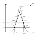
동작 시에, APD(304) 상에 입사된 반사된 광 펄스(320)는 전류 펄스를 생성하며, 이는 추가로 TIA(316)에서 증폭되고 전압 펄스로 변환된다. VGC 회로(318)는 선택적이며, 신호 감쇠를 보상할 수 있다(예를 들어, 스캐터에 대한 거리가 증가함에 따라, 수신된 전력이 1/R2로 감소함). 결과적으로, VGC 회로(318)는 거리(및 시간 지연)의 증가로 인해 VGC 회로(318)의 이득을 증가시킴으로써 이러한 효과를 보상하도록 구성된다. 그 결과, VGC 회로(318)의 출력에서의 아날로그 신호(322)는 스캔 범위에 걸쳐 주어진 스캐터에 대해 동일할 것이다. 일 예에서, 아날로그 신호(322)는 APD(304)의 순시 출력을 추적한다. VGC 회로(318) 이후에, 아날로그 신호(322)는 TDC(308) 및 적분기(310) 둘 모두에 제공된다. [0036] In operation, the reflected
[0037]
일 양상에서, TDC(308)는 레이저(206)의 발사(START)와 함께 카운팅을 시작하고 그것이 반사된 빔을 수신할 때(이는 본질적으로 STOP을 생성함) 카운트하는 고속 카운터이다. 일 예에서, TDC(308)는 다수의 측정 채널들을 구현할 수 있으며, 여기서 각각의 채널은 상이한 임계치들에서 트리거되는 다수의 STOP들을 등록할 수 있다. 도 4a의 예에서, TDC(308)는 2개의 채널들, 즉 채널 1 및 채널 2를 구현하며, 여기서 각각의 채널은 2개의 STOP들을 지원한다. 둘 모두의 채널들은 LIDAR 시스템(202)이 펄스(예를 들어, 레이저 펄스(112))를 발사할 때 준비(armed)되고, 이들은 반사된 신호(아날로그 신호(322)로 표현됨)가 미리 정의된 임계치를 교차할 때까지 계속 유지된다. 이 지점에서, TDC(308)는 STOP을 등록한다. 예시된 예에서, 스톱(stop)들에 관한 정보(예를 들어, 타임스탬프 및 연관된 전압 값)는 디지털 데이터(324)로서 TDC(308)로부터 출력될 수 있다. 도 4a는 채널 당 2개의 STOP들을 생성하는 것으로 TDC(308)를 예시하지만, TDC(308)는 2개 또는 그 초과를 포함하여 채널 당 임의의 수의 STOP들을 생성하도록 구성될 수 있다. [0037]
In an aspect, the
[0038]
도 4a에 도시된 예시적인 타이밍도(400)에서, TDC(308)는 채널 1에 대한 2개의 STOP들(즉, T1 1, T1 2) 및 채널 2에 대한 2개의 STOP들(즉, T2 1, T2 2)을 생성할 것이다. STOP들은 디지털 시간 데이터(324)로서 TDC(308)에 의해 출력될 수 있다. 각각의 신호 기울기는 T2 1-T1 1 또는 T1 2-T2 2에 대한 카운터 값들 간의 차이에 의해 결정될 수 있다. 또한, 반사된 신호의 중심은 타임스탬프들(T1 1 및 T1 2) 사이 또는 타임스탬프들(T2 1 및 T2 2) 사이의 평균 시간으로서 측정될 수 있다. 아날로그 신호(322)의 기울기는 펄스의 최대(즉, 피크) 값의 추정을 허용할 수 있다. 예를 들어, 도 4b는 아날로그 신호(322)의 최대 값을 추정하는 예시적인 방법을 예시한다. 이 예에서, 직선들(402 및 404)이 TDC(308)에 의해 생성된 다양한 STOP들에 기초하여 생성되는 선형 보간이 적용될 수 있다. 즉, 직선(402)은 지점들(406 및 408)을 통해 그려질 수 있는데, 여기서 지점(406)은 타임스탬프(T1 1)에서의 전압 값에 대응하고 지점(408)은 타임스탬프(T2 1)에서의 전압 값에 대응한다. 유사하게, 직선(404)은 지점들(410 및 412)을 통해 그려지는데, 여기서 지점(410)은 타임스탬프(T1 2)에서의 전압 값에 대응하고 지점(412)은 타임스탬프(T2 2)에서의 전압 값에 대응한다. 그 후, 직선들(402 및 404)은 이들이 교차할 때까지 연장될 수 있다. 도 4b에 도시된 바와 같이, 직선들(402, 404)은 교차점(414)을 형성한다. 교차점(414)에서의 전압 값(I)은 아날로그 신호(322)의 최대 값의 추정을 나타낼 수 있다. [0038] In the exemplary timing diagram 400 shown in FIG. 4A, the
[0039]
따라서, 위에서 도시된 바와 같이, 도 4b에 도시된 곡선 상에 로케이팅된 지점들은 아날로그 신호의 즉각적인 전력을 나타내며, 반사된 광 펄스의 최대(예를 들어, 피크) 값을 추정하는데 활용될 수 있다. 그러나, 일부 예들에서, 반사된 광 펄스의 총 반사된 에너지의 추정을 제공하는 것이 바람직할 수 있다. 일 예에서, 반사된 광 펄스의 총 반사된 에너지는 도 4b의 아날로그 신호(322)로서 도시된 곡선 아래의 영역에 의해 표현된다. [0039]
Thus, as shown above, the points located on the curve shown in FIG. 4B represent the instantaneous power of the analog signal and can be utilized to estimate the maximum (e.g., peak) value of the reflected optical pulse . However, in some instances, it may be desirable to provide an estimate of the total reflected energy of the reflected light pulses. In one example, the total reflected energy of the reflected optical pulses is represented by the area under the curve shown as
[0040]
그러나, TDC(308)의 출력에만 기초한 총 반사된 에너지의 추정은, 아날로그 신호(322)의 측정들이 강한 노이즈가 있는데서 수행되기 때문에 부정확할 수 있으며, 이는 대응하는 시간 데이터를 측정하는 데 있어서의 에러들에 기여할 수 있다. 따라서, TDC(308)의 출력에만 기초한 총 반사된 에너지의 측정의 정확도는 상대적으로 낮을 수 있다. [0040]
However, the estimation of the total reflected energy based only on the output of the
[0041]
따라서, 본원에서 개시된 실시예들은 TDC(308)에 병렬로 적분기(310)를 추가하는 것을 포함한다. 적분기(310)는 미리 정의된 시간 간격에 걸쳐 아날로그 신호(322)를 적분하도록 구성된다. 일 양상에서, 적분기(310)는 수동, 능동 또는 수동 및 능동의 결합 컴포넌트들, 예컨대, Op-Amp 적분기 또는 커패시터, 또는 유사한 기능성을 갖는 다른 디바이스를 이용하여 구현될 수 있다. [0041]
Thus, the embodiments disclosed herein include adding an
[0042]
적분기(310)는 아날로그 신호(322)의 하나 또는 그 초과의 펄스들에 의해 생성된 전하를 축적하도록 구성되며, ADC(312)는 적분기(310)의 출력에 축적된 전하의 디지털 샘플들(326)을 생성하도록 구성된다. 그 후, 디지털 샘플들(326)은 디지털 시간 데이터(324)(즉, TDC STOP 데이터)와 함께, 프로세서(314)에 제공될 수 있으며, 이 프로세서(314)는 스캔 데이터를 사후-프로세싱하고 디지털 시간 데이터(324)를 디지털 샘플들(326)과 상관시켜 총 반사된 에너지 및/또는 레이저가 입사되는 오브젝트의 반사도의 추정(328)을 생성한다. [0042]
The
[0043]
예로서, 도 4c는 반사된 광 펄스의 스캔을 예시하고 도 4d는 반사된 광 펄스의 연속적인 스캔을 예시한다. 이 예에서, 도 4c 및 도 4d의 양자의 스캔들에서 반사된 광 펄스는 유사하지만 동일하지는 않다. 그러나, TDC(308)에 의해 생성된 임계 크로싱(threshold crossing)들의 타임스탬프들은 일부 에러들을 가진 채로 측정될 수 있다. [0043]
By way of example, FIG. 4C illustrates a scan of a reflected light pulse and FIG. 4D illustrates a continuous scan of a reflected light pulse. In this example, the reflected light pulses in both scans of Figures 4c and 4d are similar but not identical. However, the time stamps of the threshold crossings generated by the
[0044]
아래의 표 1은 도 4c 및 도 4d의 연속적인 스캔들에 대해 TDC(308)에 의해 생성된 타임스탬프들의 예시적인 값들을 예시한다.

표 1Table 1
[0045]
위의 표에서 알 수 있는 바와 같이, 제 2 스캔에 대한 단지 하나의 타임스탬프들 사이에 1ns의 차이가 존재한다. 즉, 타임스탬프(T1 11)는 TDC(308)에 의해 568ns로 측정되는 반면에, 타임스탬프(T1 21)는 569ns로 측정된다. 결과적으로, 타임스탬프 값들만을 사용하여, 도 4c의 스캔에 대한 최대 값(예를 들어, 교차점(414)에서의 전압 값(I))의 추정은 3V의 값을 발생시키는 반면에, 도 4D의 스캔에 대한 최대 값의 추정은 3.1V의 값을 발생시킨다. 이러한 최대 값의 추정들에 기초한 총 반사된 에너지의 추정들은 심각한 에러를 초래할 수 있다. [0045] As can be seen in the above table, there is a 1 ns difference between only one time stamp for the second scan. That is, the time stamp (T 1 11 ) is measured by the
[0046]
따라서, 본원에서 제공되는 양상들은 ADC(312)에 의해 제공된 디지털 샘플들(326)을 활용함으로써 아날로그 신호(322)의 최대 값의 추정들을 개선하고 그리고/또는 총 반사된 에너지의 추정들을 개선할 수 있다. 즉, 일부 양상들에서, 적분기(310)로부터 유도된 값들(예를 들어, 디지털 샘플들(326))은, 아날로그 신호(322)의 최대 값 및/또는 총 반사된 에너지를 추정할 때 정규화 계수(normalizing coefficient)로서 사용될 수 있다. 예를 들어, 디지털 샘플들(326)이 45mV 로서 아날로그 신호(322)의 펄스 에너지(E)(즉, E = 45mV)를 표시한다고 가정한다. 다음으로, 직사각형의 영역은 총 반사된 에너지(E)에 선형적으로 비례한다는 가정이 이루어질 수 있다. 가정된 직사각형은 아날로그 신호(322)의 최대 값(예를 들어, 교차점(414)에서의 전압 값(I))과 동일한 높이 및 아날로그 신호(322)의 펄스 지속기간과 동일한 폭을 갖는 것으로 정의된다. 일 예에서, 펄스 지속기간은 TDC(308)에 의해 사용되는 채널들의 대응하는 타임스탬프들 간의 평균일 수 있다. 즉, 도 4c의 스캔의 아날로그 신호(322)의 펄스 기간은 ![]()
![]()
[0047]
유사하게, 도 4d의 스캔의 아날로그 신호(322)의 펄스 기간은 
[0048]
위로부터 알 수 있는 바와 같이, 타임스탬프들에만 기초한 아날로그 신호(322)의 최대 값의 추정은 도 4c의 스캔에 대해 3V의 값을 그리고 도 4d의 스캔에 대해 3.11V의 값을 렌더링할 것이다. 그러나, 디지털 샘플들(326)에 의해 표현된 바와 같이 펄스 에너지를 인수분해하는 것은 각각 3mV/ns 및 3.1mV/ns의 값들을 발생시킨다. [0048]
As can be seen from above, the estimation of the maximum value of the
[0049]
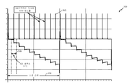
도 5는 LIDAR 시스템(202)의 적분기(310) 및 ADC(312)의 동작을 예시하는 타이밍도(500)이다. LIDAR 시스템(202)에 의해 생성된 레이저 펄스는 APD(304)에 의해 수신되고 차례로 APD(304)의 출력에서 전기 펄스들을 생성하는 균등 간격의 동일한 스캐터들에 의해 반사된다. 증폭기(306)를 통과한 후에, 이들 에코들은 균등한 진폭의 등거리 펄스들(502)로서 나타난다. [0049]
5 is a timing diagram 500 illustrating the operation of the
[0050]
따라서, 적분기(310)는 수신된 모든 반사된 펄스들에 의해 생성된 전하 및 스캔 간격(508) 동안의 노이즈를 (미리 정의된 ADC 샘플링 시간(506)에 걸쳐) 축적한다. 동시에, ADC(312)는 스캔 간격(508) 동안 적분기(310)의 출력에 축적된 전하의 다수의 샘플들을 디지털화한다. 일 양상에서, 스캔 간격(508)은 LIDAR 시스템(202)의 동작의 범위에 대응한다. 예를 들어, 동작의 범위는, LIDAR 시스템(202)이 주어진 레이저 펄스에 대한 모든 펄스들(502)을 수신할 것으로 예상하는 시간의 범위에 대응할 수 있다. [0050]
Thus, the
[0051]
그 후, 디지털 샘플들(326)은 디지털 시간 데이터(324)(즉, TDC STOP 데이터)와 함께, 프로세서(314)에 제공될 수 있으며, 이 프로세서(314)는 스캔 데이터를 사후-프로세싱하고 디지털 시간 데이터(324)를 디지털 샘플들(326)과 상관시켜 총 반사된 에너지 및/또는 레이저가 입사되는 오브젝트의 반사도의 추정(328)을 생성한다. [0051]
The
[0052]
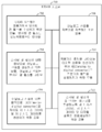
도 6은 LIDAR 시스템에서 반사된 신호 강도 측정을 수행하는 예시적인 프로세스(600)를 예시하는 흐름도이다. 프로세스(600)는 도 2의 LIDAR 시스템(202)에 의해 수행된 하나의 가능한 프로세스이다. 프로세스 블록(602)에서, 도 3의 검출기(302)는 반사된 광 펄스를 수신한다(예를 들어, APD(304)는 반사된 광 펄스(320)를 수신함). 프로세스 블록(604)에서, 증폭기(306)는 반사된 광 펄스(320)에 대한 응답으로 아날로그 신호(322)를 생성한다. 프로세스 블록(606)에서, TDC(308)는 반사된 광 펄스(320)에 대응하는 적어도 2개의 STOP들을 나타내는 제 1 및 제 2 디지털 시간 데이터(324)를 생성한다. 프로세스 블록(608)에서, 적분기(310)는 스캔 간격(508)에 걸쳐 아날로그 신호(322)를 적분한다. 프로세스 블록(610)에서, ADC(312)는 적분기(310)의 출력을 샘플링하여 적분기(310)의 출력을 나타내는 하나 또는 그 초과의 디지털 샘플들(326)을 생성한다. 프로세스 블록(612)에서, 프로세서(314)는 오브젝트(110)의 총 반사된 에너지 및/또는 반사도 값의 추정(328)을 제공하도록, 디지털 샘플(들)(326)과 함께 제 1 및 제 2 디지털 시간 데이터(324)를 프로세싱한다. [0052]
6 is a flow chart illustrating an
[0053]
도 7은 LIDAR 시스템에서 사용될 수 있고 본원에서 교시된 바와 같이 반사된 신호 강도 측정을 수행하는 것을 지원하도록 구성된 컴포넌트들의 여러 샘플 양상들의 단순화된 블록도이다. LIDAR 시스템(700)은 LIDAR 시스템(102 및/또는 202)의 하나의 가능한 구현이다. LIDAR 시스템의 검출기에서 반사된 광 펄스를 수신하기 위한 모듈(702)은 적어도 일부 양상들에서, 예를 들어, 본원에서 논의된 바와 같은 검출기(210) 및/또는 APD(304)에 대응할 수 있다. 반사된 광 펄스에 대한 응답으로 아날로그 신호를 생성하기 위한 모듈(704)은 적어도 일부 양상들에서, 예를 들어, 본원에서 논의된 바와 같은 증폭기(306)에 대응할 수 있다. 제 1 시간 데이터 및 제 2 시간 데이터를 생성하기 위한 모듈(706)은 적어도 일부 양상들에서, 예를 들어, 본원에서 논의된 바와 같은 TDC(308)에 대응할 수 있다. 아날로그 신호를 적분기로 적분하기 위한 모듈(708)은 적어도 일부 양상들에서, 예를 들어, 본원에서 논의된 바와 같은 적분기(310)에 대응할 수 있다. 적분기의 출력을 샘플링하기 위한 모듈(710)은 적어도 일부 양상들에서, 예를 들어, 본원에서 논의 바와 같은 ADC(312)에 대응할 수 있다. 제 1 시간 데이터, 제 2 시간 데이터 및 디지털 샘플을 프로세싱하기 위한 모듈(712)은 적어도 일부 양상들에서, 예를 들어, 본원에서 논의된 바와 같은 프로세서(314), LIDAR 제어 유닛(222) 및/또는 프로세서(212)에 대응할 수 있다. [0053]
7 is a simplified block diagram of various sample aspects of components that may be used in the LIDAR system and configured to support performing a reflected signal strength measurement as taught herein. The
[0054] 도 7의 모듈들(702-712)의 기능성은, 본원의 교시들에 부합하는 다양한 방식들로 구현될 수 있다. 일부 설계들에서, 이들 모듈들의 기능성은, 하나 또는 그 초과의 전기 컴포넌트들로서 구현될 수 있다. 일부 설계들에서, 이들 모듈들의 기능성은, 하나 또는 그 초과의 프로세서 컴포넌트들을 포함하는 프로세싱 시스템으로 구현될 수 있다. 일부 설계들에서, 이들 모듈들의 기능성은, 예를 들어, 하나 또는 그 초과의 집적 회로들(예를 들어, ASIC)의 적어도 일부를 사용하여 구현될 수 있다. 본원에 논의된 바와 같이, 집적 회로는, 프로세서, 소프트웨어, 다른 관련 컴포넌트들, 또는 이들의 일부 결합을 포함할 수 있다. 따라서, 상이한 모듈들의 기능성은, 예를 들어, 집적 회로의 상이한 서브세트들로서, 소프트웨어 모듈들의 세트의 상이한 서브세트들로, 또는 이들의 결합으로 구현될 수 있다. 또한, (예를 들어, 집적 회로 및/또는 소프트웨어 모듈들의 세트의) 주어진 서브세트는, 1개 초과의 모듈에 대한 기능성의 적어도 일부를 제공할 수 있다는 것이 인지될 것이다. [0054] The functionality of the modules 702-712 of FIG. 7 may be implemented in various manners consistent with the teachings herein. In some designs, the functionality of these modules may be implemented as one or more electrical components. In some designs, the functionality of these modules may be implemented in a processing system that includes one or more processor components. In some designs, the functionality of these modules may be implemented using, for example, at least a portion of one or more integrated circuits (e.g., an ASIC). As discussed herein, an integrated circuit may include a processor, software, other related components, or some combination thereof. Thus, the functionality of the different modules may be implemented, for example, as different subsets of the integrated circuit, different subsets of the set of software modules, or a combination thereof. It will also be appreciated that a given subset (e.g., of an integrated circuit and / or a set of software modules) may provide at least a portion of functionality for more than one module.
[0055] 부가적으로, 도 7에 의해 표현된 컴포넌트들 및 기능들 뿐만 아니라 본원에 설명된 다른 컴포넌트들 및 기능들은, 임의의 적합한 수단을 사용하여 구현될 수 있다. 그러한 수단은 또한, 본원에 교시된 바와 같은 대응하는 구조를 사용하여 적어도 부분적으로 구현될 수 있다. 예를 들어, 도 7의 컴포넌트들을 "위한 모듈"과 함께 위에서 설명된 컴포넌트들은 또한, 유사하게 지정된 기능성을 "위한 수단"에 대응할 수 있다. 따라서, 일부 양상들에서, 그러한 수단 중 하나 또는 그 초과는, 프로세서 컴포넌트들, 집적 회로들, 또는 본원에 교시된 바와 같은 다른 적합한 구조 중 하나 또는 그 초과를 사용하여 구현될 수 있다. [0055] In addition, the components and functions represented by FIG. 7 as well as other components and functions described herein may be implemented using any suitable means. Such means may also be implemented, at least in part, using corresponding structures as taught herein. For example, the components described above in conjunction with "module for components " of FIG. 7 may also correspond to" means for " similarly designated functionality. Thus, in some aspects, one or more of such means may be implemented using one or more of the following: processor components, integrated circuits, or other suitable structures as taught herein.
[0056] 정보 및 신호들이 다양한 상이한 기술들 및 기법들 중 임의의 기술 및 기법을 사용하여 표현될 수 있다는 것을 당업자들은 인지할 것이다. 예를 들어, 위의 설명 전반에 걸쳐 참조될 수 있는 데이터, 명령들, 커맨드들, 정보, 신호들, 비트들, 심볼들, 및 칩들은 전압들, 전류들, 전자기파들, 자기장들 또는 자기 입자들, 광학 필드들 또는 광학 입자들, 또는 이들의 임의의 결합에 의해 표현될 수 있다. [0056] Those skilled in the art will recognize that information and signals may be represented using any of a variety of different technologies and techniques. For example, data, instructions, commands, information, signals, bits, symbols, and chips that may be referenced throughout the above description may refer to voltages, currents, electromagnetic waves, , Optical fields or optical particles, or any combination thereof.
[0057] 추가로, 본원에 개시된 실시예들과 관련하여 설명된 다양한 예시적인 로직 블록들, 모듈들, 회로들, 및 알고리즘 단계들이 전자 하드웨어, 컴퓨터 소프트웨어, 또는 이 둘의 결합들로서 구현될 수 있음을 당업자들은 인지할 것이다. 하드웨어와 소프트웨어의 이러한 상호교환 가능성을 명확히 예시하기 위해, 다양한 예시적인 컴포넌트들, 블록들, 모듈들, 회로들, 및 단계들은 그들의 기능성 관점들에서 일반적으로 위에서 설명되었다. 이러한 기능성이 하드웨어로 구현되는지 또는 소프트웨어로 구현되는지 여부는 전체 시스템에 부과되는 설계 제약들 및 특정 애플리케이션에 의존한다. 당업자들은, 설명된 기능성을 각각의 특정 애플리케이션 마다 다양한 방식들로 구현할 수 있지만, 이러한 구현 결정들이 본 발명의 범위를 벗어나게 하는 것으로 해석되어서는 안 된다. [0057] In addition, those skilled in the art will appreciate that the various illustrative logical blocks, modules, circuits, and algorithm steps described in connection with the embodiments disclosed herein may be implemented as electronic hardware, computer software, or combinations of both I will recognize. To clearly illustrate this interchangeability of hardware and software, various illustrative components, blocks, modules, circuits, and steps have been described above generally in their functional aspects. Whether such functionality is implemented in hardware or software depends upon the particular application and design constraints imposed on the overall system. Skilled artisans may implement the described functionality in varying ways for each particular application, but such implementation decisions should not be interpreted as causing a departure from the scope of the present invention.
[0058] 본원에서 개시된 실시예들과 관련하여 설명되는 방법들, 시퀀스들, 및/또는 알고리즘들은 직접적으로 하드웨어로, 프로세서에 의해 실행되는 소프트웨어 모듈로, 또는 이 둘의 결합으로 실현될 수 있다. 소프트웨어 모듈은 RAM 메모리, 플래시 메모리, ROM 메모리, EPROM 메모리, EEPROM 메모리, 레지스터들, 하드디스크, 제거 가능 디스크, CD-ROM, 또는 당업계에 알려진 임의의 다른 형태의 저장 매체에 상주할 수 있다. 예시적인 저장 매체는, 프로세서가 저장 매체로부터 정보를 판독하고, 저장 매체에 정보를 기록할 수 있도록 프로세서에 커플링된다. 대안으로, 저장 매체는 프로세서에 통합될 수 있다. [0058] The methods, sequences, and / or algorithms described in connection with the embodiments disclosed herein may be embodied directly in hardware, in a software module executed by a processor, or in a combination of the two. The software module may reside in RAM memory, flash memory, ROM memory, EPROM memory, EEPROM memory, registers, a hard disk, a removable disk, a CD-ROM, or any other form of storage medium known in the art. An exemplary storage medium is coupled to the processor such that the processor can read information from, and write information to, the storage medium. Alternatively, the storage medium may be integrated into the processor.
[0059] 따라서, 본 발명의 실시예는 LIDAR 시스템에서 반사된 신호 강도 측정을 수행하기 위한 방법을 구현하는 컴퓨터-판독 가능 매체를 포함할 수 있다. 따라서, 본 발명은 예시된 예들로 제한되지 않으며, 본원에서 설명된 기능성을 수행하기 위한 임의의 수단이 본 발명의 실시예들에 포함된다. [0059] Accordingly, embodiments of the present invention may include a computer-readable medium embodying a method for performing signal strength measurements reflected in a LIDAR system. Accordingly, the present invention is not limited to the illustrated examples, and any means for performing the functionality described herein is included in embodiments of the present invention.
[0060] 위의 개시는 본 발명의 예시적인 실시예들을 도시하지만, 첨부된 청구항들에 의해 정의되는 본 발명의 범위를 벗어남 없이 본원에서 다양한 변경들 및 수정들이 이루어질 수 있다는 것이 주의되어야 한다. 본원에 설명된 본 발명의 실시예들에 따른 방법 청구항들의 기능들, 단계들 및/또는 액션들이 임의의 특정 순서로 수행될 필요는 없다. 또한, 본 발명의 엘리먼트들이 단수로 설명되거나 청구될 수 있지만, 단수에 대한 제한이 명시적으로 언급되지 않으면 복수가 고려된다. [0060] While the foregoing disclosure illustrates exemplary embodiments of the invention, it should be noted that various changes and modifications may be made herein without departing from the scope of the invention as defined by the appended claims. The functions, steps and / or actions of the method claims according to embodiments of the invention described herein need not be performed in any particular order. Furthermore, although elements of the invention may be described or claimed in the singular, the plural is contemplated unless limitation to the singular is explicitly stated.
Claims (25)
LIDAR 시스템의 검출기에서 반사된 광 펄스를 수신하는 단계 ― 상기 반사된 광 펄스는 오브젝트로부터 반사됨 ― ;
상기 반사된 광 펄스에 대한 응답으로 아날로그 신호를 생성하는 단계 ― 상기 아날로그 신호는 상기 반사된 광 펄스를 나타냄 ― ;
상기 아날로그 신호에 대한 응답으로 TDC(time-to-digital converter)로 적어도 제 1 시간 데이터 및 제 2 시간 데이터를 생성하는 단계;
상기 아날로그 신호를 적분기로 적분하는 단계;
상기 적분기의 출력을 나타내는 디지털 샘플을 생성하기 위해 하나 또는 그 초과의 샘플링 시간들에 ADC(analog-to-digital converter)로 상기 적분기의 출력을 샘플링하는 단계; 및
상기 반사된 광 펄스의 총 반사된 에너지를 추정하도록 상기 제 1 시간 데이터, 상기 제 2 시간 데이터 및 상기 디지털 샘플을 프로세싱하는 단계를 포함하고, 상기 제 1 시간 데이터, 상기 제 2 시간 데이터 및 상기 디지털 샘플을 프로세싱하는 단계는,
상기 제 1 시간 데이터 및 상기 제 2 시간 데이터에 기초하여 상기 아날로그 신호의 펄스 지속기간을 결정하는 단계;
상기 디지털 샘플에 기초하여 상기 아날로그 신호의 펄스 에너지를 결정하는 단계; 및
상기 펄스 에너지 대 상기 펄스 지속기간의 비(ratio)에 비례하여 상기 아날로그 신호의 최대 값을 추정하는 단계를 포함하는,
LIDAR 시스템과 함께 사용하기 위한 방법.A method for use with a LIDAR (LIght Detection And Ranging) system,
Receiving a reflected optical pulse at a detector of a LIDAR system, the reflected optical pulse reflected from an object;
Generating an analog signal in response to the reflected optical pulse, the analog signal representing the reflected optical pulse;
Generating at least first time data and second time data with a time-to-digital converter (TDC) in response to the analog signal;
Integrating the analog signal with an integrator;
Sampling an output of the integrator with an analog-to-digital converter (ADC) at one or more sampling times to produce a digital sample representative of the output of the integrator; And
Processing the first time data, the second time data and the digital samples to estimate a total reflected energy of the reflected light pulses, wherein the first time data, the second time data, and the digital Wherein processing the sample comprises:
Determining a pulse duration of the analog signal based on the first time data and the second time data;
Determining a pulse energy of the analog signal based on the digital sample; And
And estimating a maximum value of the analog signal in proportion to a ratio of the pulse energy to the pulse duration.
A method for use with a LIDAR system.
상기 제 1 시간 데이터는 상기 아날로그 신호가 제 1 임계치에 도달하는 것에 대응하는 제 1 타임스탬프(time stamp)를 포함하고 상기 제 2 시간 데이터는 상기 아날로그 신호가 제 2 임계치에 도달하는 것에 대응하는 제 2 타임스탬프를 포함하는,
LIDAR 시스템과 함께 사용하기 위한 방법.The method according to claim 1,
Wherein the first time data comprises a first time stamp corresponding to the analog signal reaching a first threshold and the second time data comprises a second time data corresponding to the analog signal reaching a second threshold 2 < / RTI > time stamp,
A method for use with a LIDAR system.
상기 아날로그 신호를 적분하는 단계는 상기 LIDAR 시스템의 스캔 간격에 걸쳐 상기 아날로그 신호를 적분하는 단계를 포함하는,
LIDAR 시스템과 함께 사용하기 위한 방법.The method according to claim 1,
Wherein integrating the analog signal comprises integrating the analog signal over a scan interval of the LIDAR system.
A method for use with a LIDAR system.
상기 스캔 간격은 상기 LIDAR 시스템의 동작의 범위에 대응하는,
LIDAR 시스템과 함께 사용하기 위한 방법.The method of claim 3,
Wherein the scan interval corresponds to a range of operation of the LIDAR system,
A method for use with a LIDAR system.
상기 아날로그 신호는 상기 검출기의 감광성 엘리먼트(photosensitive element)의 순시 출력을 추적하는,
LIDAR 시스템과 함께 사용하기 위한 방법.The method according to claim 1,
Wherein the analog signal tracks an instantaneous output of a photosensitive element of the detector,
A method for use with a LIDAR system.
상기 반사된 광 펄스의 총 반사된 에너지를 추정하도록 상기 제 1 시간 데이터, 상기 제 2 시간 데이터 및 상기 디지털 샘플을 프로세싱하는 단계는,
상기 제 1 시간 데이터, 상기 제 2 시간 데이터 및 상기 디지털 샘플에 기초하여 상기 오브젝트의 반사도(reflectance)를 추정하는 단계를 더 포함하는,
LIDAR 시스템과 함께 사용하기 위한 방법.The method according to claim 1,
Wherein processing the first time data, the second time data and the digital samples to estimate a total reflected energy of the reflected light pulses comprises:
Further comprising estimating a reflectance of the object based on the first time data, the second time data, and the digital sample.
A method for use with a LIDAR system.
반사된 광 펄스를 수신하도록 구성된 검출기 ― 상기 반사된 광 펄스는 오브젝트로부터 반사됨 ― ;
상기 반사된 광 펄스에 대한 응답으로 아날로그 신호를 생성하기 위해 상기 검출기에 커플링되는 증폭기 ― 상기 아날로그 신호는 상기 반사된 광 펄스를 나타냄 ― ;
상기 아날로그 신호에 대한 응답으로 적어도 제 1 시간 데이터 및 제 2 시간 데이터를 생성하도록 상기 증폭기에 커플링되는 TDC(time-to-digital converter);
상기 아날로그 신호를 적분하도록 상기 증폭기에 커플링되는 적분기;
상기 적분기의 출력을 나타내는 디지털 샘플을 생성하기 위해 하나 또는 그 초과의 샘플링 시간들에 상기 적분기의 출력을 샘플링하도록 커플링되는 ADC(analog-to-digital converter); 및
상기 반사된 광 펄스의 총 반사된 에너지를 추정하기 위해 상기 제 1 시간 데이터, 상기 제 2 시간 데이터 및 상기 디지털 샘플을 프로세싱하도록 상기 TDC 및 상기 ADC에 커플링되는 프로세서를 포함하고, 상기 프로세서는 추가로,
상기 제 1 시간 데이터 및 상기 제 2 시간 데이터에 기초하여 상기 아날로그 신호의 펄스 지속기간을 결정하고;
상기 디지털 샘플에 기초하여 상기 아날로그 신호의 펄스 에너지를 결정하고; 그리고
상기 펄스 에너지 대 상기 펄스 지속기간의 비에 비례하여 상기 아날로그 신호의 최대 값을 추정하도록 구성되는,
LIDAR 시스템.As a LIDAR (LIght Detection And Ranging) system,
A detector configured to receive a reflected light pulse, the reflected light pulse reflected from an object;
An amplifier coupled to the detector to generate an analog signal in response to the reflected optical pulse, the analog signal representing the reflected optical pulse;
A time-to-digital converter (TDC) coupled to the amplifier to generate at least first time data and second time data in response to the analog signal;
An integrator coupled to the amplifier to integrate the analog signal;
An analog-to-digital converter (ADC) coupled to sample the output of the integrator at one or more sampling times to produce a digital sample representative of the output of the integrator; And
And a processor coupled to the TDC and the ADC to process the first time data, the second time data, and the digital sample to estimate a total reflected energy of the reflected light pulse, in,
Determine a pulse duration of the analog signal based on the first time data and the second time data;
Determine a pulse energy of the analog signal based on the digital sample; And
And to estimate a maximum value of the analog signal in proportion to a ratio of the pulse energy to the pulse duration.
LIDAR system.
상기 제 1 시간 데이터는 상기 아날로그 신호가 제 1 임계치에 도달하는 것에 대응하는 제 1 타임스탬프를 포함하고 상기 제 2 시간 데이터는 상기 아날로그 신호가 제 2 임계치에 도달하는 것에 대응하는 제 2 타임스탬프를 포함하는,
LIDAR 시스템.8. The method of claim 7,
Wherein the first time data comprises a first time stamp corresponding to the analog signal reaching a first threshold and the second time data comprises a second time stamp corresponding to the analog signal reaching a second threshold Including,
LIDAR system.
상기 적분기는 추가로, 상기 LIDAR 시스템의 스캔 간격에 걸쳐 상기 아날로그 신호를 적분하도록 구성되는,
LIDAR 시스템.8. The method of claim 7,
Wherein the integrator is further configured to integrate the analog signal over a scan interval of the LIDAR system,
LIDAR system.
상기 스캔 간격은 상기 LIDAR 시스템의 동작의 범위에 대응하는,
LIDAR 시스템.10. The method of claim 9,
Wherein the scan interval corresponds to a range of operation of the LIDAR system,
LIDAR system.
상기 증폭기는 상기 아날로그 신호가 상기 검출기의 감광성 엘리먼트의 순시 출력을 추적하도록 상기 아날로그 신호를 생성하게 구성되는,
LIDAR 시스템.8. The method of claim 7,
Wherein the amplifier is configured to generate the analog signal such that the analog signal tracks the instantaneous output of the photosensitive element of the detector.
LIDAR system.
상기 감광성 엘리먼트는 APD(avalanche photodiode)를 포함하는,
LIDAR 시스템.12. The method of claim 11,
Wherein the photosensitive element comprises an avalanche photodiode (APD)
LIDAR system.
상기 프로세서는 추가로, 상기 제 1 시간 데이터, 상기 제 2 시간 데이터 및 상기 디지털 샘플에 기초하여 상기 오브젝트의 반사도를 추정하도록 구성되는,
LIDAR 시스템.8. The method of claim 7,
Wherein the processor is further configured to estimate a reflectivity of the object based on the first time data, the second time data, and the digital sample,
LIDAR system.
프로그램 코드를 저장하도록 적응된 메모리; 및
상기 프로그램 코드에 포함된 명령들에 액세스 및 실행하도록 상기 메모리에 커플링되는 프로세서를 포함하고, 상기 명령들은,
상기 LIDAR 시스템의 검출기에서 반사된 광 펄스를 수신하고 ― 상기 반사된 광 펄스는 오브젝트로부터 반사됨 ― ;
상기 반사된 광 펄스에 대한 응답으로 아날로그 신호를 생성하고 ― 상기 아날로그 신호는 상기 반사된 광 펄스를 나타냄 ― ;
상기 아날로그 신호에 대한 응답으로 TDC(time-to-digital converter)로 적어도 제 1 시간 데이터 및 제 2 시간 데이터를 생성하고;
상기 아날로그 신호를 적분기로 적분하고;
상기 적분기의 출력을 나타내는 디지털 샘플을 생성하기 위해 하나 또는 그 초과의 샘플링 시간들에 ADC(analog-to-digital converter)로 상기 적분기의 출력을 샘플링하고; 그리고
상기 반사된 광 펄스의 총 반사된 에너지를 추정하도록 상기 제 1 시간 데이터, 상기 제 2 시간 데이터 및 상기 디지털 샘플을 프로세싱하도록 상기 LIDAR 시스템에 지시하기 위한 것이고,
상기 제 1 시간 데이터, 상기 제 2 시간 데이터 및 상기 디지털 샘플을 프로세싱하기 위한 명령들은,
상기 제 1 시간 데이터 및 상기 제 2 시간 데이터에 기초하여 상기 아날로그 신호의 펄스 지속기간을 결정하고;
상기 디지털 샘플에 기초하여 상기 아날로그 신호의 펄스 에너지를 결정하고; 그리고
상기 펄스 에너지 대 상기 펄스 지속기간의 비에 비례하여 상기 아날로그 신호의 최대 값을 추정하기 위한 명령들을 포함하는,
LIDAR 시스템.As a LIDAR (LIght Detection And Ranging) system,
A memory adapted to store program code; And
And a processor coupled to the memory to access and execute instructions contained in the program code,
Receiving a reflected optical pulse at a detector of the LIDAR system, the reflected optical pulse reflected from an object;
Generating an analog signal in response to the reflected optical pulse, the analog signal representing the reflected optical pulse;
Generating at least first time data and second time data with a time-to-digital converter (TDC) in response to the analog signal;
Integrate the analog signal with an integrator;
Sampling the output of the integrator with an analog-to-digital converter (ADC) at one or more sampling times to produce a digital sample representative of the output of the integrator; And
To instruct the LIDAR system to process the first time data, the second time data and the digital samples to estimate a total reflected energy of the reflected light pulses,
Instructions for processing the first time data, the second time data, and the digital samples,
Determine a pulse duration of the analog signal based on the first time data and the second time data;
Determine a pulse energy of the analog signal based on the digital sample; And
And estimating a maximum value of the analog signal in proportion to a ratio of the pulse energy to the pulse duration.
LIDAR system.
상기 제 1 시간 데이터는 상기 아날로그 신호가 제 1 임계치에 도달하는 것에 대응하는 제 1 타임스탬프를 포함하고 상기 제 2 시간 데이터는 상기 아날로그 신호가 제 2 임계치에 도달하는 것에 대응하는 제 2 타임스탬프를 포함하는,
LIDAR 시스템.15. The method of claim 14,
Wherein the first time data comprises a first time stamp corresponding to the analog signal reaching a first threshold and the second time data comprises a second time stamp corresponding to the analog signal reaching a second threshold Including,
LIDAR system.
상기 프로그램 코드는, 상기 LIDAR 시스템의 스캔 간격에 걸쳐 상기 아날로그 신호를 적분하도록 상기 LIDAR 시스템에 지시하기 위한 명령들을 더 포함하는,
LIDAR 시스템.15. The method of claim 14,
The program code further comprising instructions for instructing the LIDAR system to integrate the analog signal over a scan interval of the LIDAR system,
LIDAR system.
상기 스캔 간격은 상기 LIDAR 시스템의 동작의 범위에 대응하는,
LIDAR 시스템.17. The method of claim 16,
Wherein the scan interval corresponds to a range of operation of the LIDAR system,
LIDAR system.
상기 아날로그 신호는 상기 검출기의 감광성 엘리먼트(photosensitive element)의 순시 출력을 추적하는,
LIDAR 시스템.15. The method of claim 14,
Wherein the analog signal tracks an instantaneous output of a photosensitive element of the detector,
LIDAR system.
상기 제 1 시간 데이터, 상기 제 2 시간 데이터 및 상기 디지털 샘플을 프로세싱하기 위한 명령들은,
상기 제 1 시간 데이터, 상기 제 2 시간 데이터 및 상기 디지털 샘플에 기초하여 상기 오브젝트의 반사도를 추정하기 위한 명령들을 더 포함하는,
LIDAR 시스템.15. The method of claim 14,
Instructions for processing the first time data, the second time data, and the digital samples,
Further comprising instructions for estimating a reflectivity of the object based on the first time data, the second time data, and the digital sample,
LIDAR system.
상기 LIDAR 시스템의 검출기에서 반사된 광 펄스를 수신하기 위한 수단 ― 상기 반사된 광 펄스는 오브젝트로부터 반사됨 ― ;
상기 반사된 광 펄스에 대한 응답으로 아날로그 신호를 생성하기 위한 수단 ― 상기 아날로그 신호는 상기 반사된 광 펄스를 나타냄 ― ;
상기 아날로그 신호에 대한 응답으로 TDC(time-to-digital converter)로 적어도 제 1 시간 데이터 및 제 2 시간 데이터를 생성하기 위한 수단;
상기 아날로그 신호를 적분하기 위한 수단;
상기 적분하기 위한 수단의 출력을 나타내는 디지털 샘플을 생성하도록 하나 또는 그 초과의 샘플링 시간들에 상기 적분하기 위한 수단의 출력을 샘플링하기 위한 수단; 및
상기 반사된 광 펄스의 총 반사된 에너지를 추정하도록 상기 제 1 시간 데이터, 상기 제 2 시간 데이터 및 상기 디지털 샘플을 프로세싱하기 위한 수단을 포함하고,
상기 제 1 시간 데이터, 상기 제 2 시간 데이터 및 상기 디지털 샘플을 프로세싱하기 위한 수단은,
상기 제 1 시간 데이터 및 상기 제 2 시간 데이터에 기초하여 상기 아날로그 신호의 펄스 지속기간을 결정하기 위한 수단;
상기 디지털 샘플에 기초하여 상기 아날로그 신호의 펄스 에너지를 결정하기 위한 수단; 및
상기 펄스 에너지 대 상기 펄스 지속기간의 비 에 비례하여 상기 아날로그 신호의 최대 값을 추정하기 위한 수단을 포함하는,
LIDAR 시스템.As a LIDAR (LIght Detection And Ranging) system,
Means for receiving a reflected optical pulse at a detector of the LIDAR system, the reflected optical pulse reflected from an object;
Means for generating an analog signal in response to the reflected optical pulse, the analog signal representing the reflected optical pulse;
Means for generating at least first time data and second time data with a time-to-digital converter (TDC) in response to the analog signal;
Means for integrating the analog signal;
Means for sampling an output of the means for integrating at one or more sampling times to produce a digital sample representative of an output of the means for integrating; And
And means for processing the first time data, the second time data and the digital samples to estimate a total reflected energy of the reflected light pulses,
Wherein the means for processing the first time data, the second time data and the digital sample comprises:
Means for determining a pulse duration of the analog signal based on the first time data and the second time data;
Means for determining a pulse energy of the analog signal based on the digital sample; And
And means for estimating a maximum value of the analog signal in proportion to the ratio of the pulse energy to the pulse duration.
LIDAR system.
상기 제 1 시간 데이터는 상기 아날로그 신호가 제 1 임계치에 도달하는 것에 대응하는 제 1 타임스탬프를 포함하고 상기 제 2 시간 데이터는 상기 아날로그 신호가 제 2 임계치에 도달하는 것에 대응하는 제 2 타임스탬프를 포함하는,
LIDAR 시스템.21. The method of claim 20,
Wherein the first time data comprises a first time stamp corresponding to the analog signal reaching a first threshold and the second time data comprises a second time stamp corresponding to the analog signal reaching a second threshold Including,
LIDAR system.
상기 아날로그 신호를 적분하기 위한 수단은, 상기 LIDAR 시스템의 스캔 간격에 걸쳐 상기 아날로그 신호를 적분하기 위한 수단을 더 포함하는,
LIDAR 시스템.21. The method of claim 20,
Wherein the means for integrating the analog signal further comprises means for integrating the analog signal over a scan interval of the LIDAR system.
LIDAR system.
상기 스캔 간격은 상기 LIDAR 시스템의 동작의 범위에 대응하는,
LIDAR 시스템.23. The method of claim 22,
Wherein the scan interval corresponds to a range of operation of the LIDAR system,
LIDAR system.
상기 아날로그 신호는 상기 검출기의 감광성 엘리먼트(photosensitive element)의 순시 출력을 추적하는,
LIDAR 시스템.21. The method of claim 20,
Wherein the analog signal tracks an instantaneous output of a photosensitive element of the detector,
LIDAR system.
상기 반사된 광 펄스의 총 반사된 에너지를 추정하도록 상기 제 1 시간 데이터, 상기 제 2 시간 데이터 및 상기 디지털 샘플을 프로세싱하기 위한 수단은,
상기 제 1 시간 데이터, 상기 제 2 시간 데이터 및 상기 디지털 샘플에 기초하여 상기 오브젝트의 반사도(reflectance)를 추정하기 위한 수단을 더 포함하는,
LIDAR 시스템.
21. The method of claim 20,
Wherein the means for processing the first time data, the second time data and the digital samples to estimate the total reflected energy of the reflected light pulses comprises:
Further comprising means for estimating a reflectance of the object based on the first time data, the second time data, and the digital sample.
LIDAR system.
Applications Claiming Priority (5)
| Application Number | Priority Date | Filing Date | Title |
|---|---|---|---|
| US201562234328P | 2015-09-29 | 2015-09-29 | |
| US62/234,328 | 2015-09-29 | ||
| US15/230,911 | 2016-08-08 | ||
| US15/230,911 US11131756B2 (en) | 2015-09-29 | 2016-08-08 | LIDAR system with reflected signal strength measurement |
| PCT/US2016/046123 WO2017058367A1 (en) | 2015-09-29 | 2016-08-09 | Lidar system with reflected signal strength measurement |
Publications (1)
| Publication Number | Publication Date |
|---|---|
| KR20180063211A true KR20180063211A (en) | 2018-06-11 |
Family
ID=58408834
Family Applications (1)
| Application Number | Title | Priority Date | Filing Date |
|---|---|---|---|
| KR1020187012214A KR20180063211A (en) | 2015-09-29 | 2016-08-09 | LIDAR system with reflected signal strength measurement |
Country Status (7)
| Country | Link |
|---|---|
| US (1) | US11131756B2 (en) |
| EP (1) | EP3356853B1 (en) |
| JP (1) | JP2018528437A (en) |
| KR (1) | KR20180063211A (en) |
| CN (1) | CN108139481B (en) |
| BR (1) | BR112018006392A2 (en) |
| WO (1) | WO2017058367A1 (en) |
Families Citing this family (39)
| Publication number | Priority date | Publication date | Assignee | Title |
|---|---|---|---|---|
| JP6791645B2 (en) * | 2016-03-29 | 2020-11-25 | 本田技研工業株式会社 | Optical communication equipment, optical communication system, and optical communication method |
| WO2018107298A1 (en) * | 2016-12-16 | 2018-06-21 | Cartier Energie Eolienne Inc. | System and method for monitoring blade deflection of wind turbines |
| US10139478B2 (en) | 2017-03-28 | 2018-11-27 | Luminar Technologies, Inc. | Time varying gain in an optical detector operating in a lidar system |
| US10641874B2 (en) * | 2017-03-29 | 2020-05-05 | Luminar Technologies, Inc. | Sizing the field of view of a detector to improve operation of a lidar system |
| US10509113B2 (en) | 2017-04-07 | 2019-12-17 | ActLight SA | Techniques for performing time of flight measurements |
| CN116359934A (en) * | 2017-07-20 | 2023-06-30 | 深圳市大疆创新科技有限公司 | System and method for optical distance measurement |
| KR102019382B1 (en) | 2017-09-29 | 2019-09-06 | 현대오트론 주식회사 | Distance detection sensor and operating method thereof |
| JP6907886B2 (en) * | 2017-10-27 | 2021-07-21 | オムロン株式会社 | Displacement sensor |
| CN110646806B (en) * | 2018-06-26 | 2021-11-30 | 深圳市速腾聚创科技有限公司 | Laser radar and laser radar control method |
| CN108845331B (en) * | 2018-06-28 | 2021-01-12 | 中国电子科技集团公司信息科学研究院 | Laser radar detection system |
| CN108614255A (en) * | 2018-06-28 | 2018-10-02 | 中国电子科技集团公司信息科学研究院 | A kind of reading circuit |
| CN109245765B (en) * | 2018-06-29 | 2022-06-07 | 西安电子科技大学昆山创新研究院 | TDC _ ADC multiplexing techniques |
| CN109171787B (en) * | 2018-08-27 | 2021-02-26 | 苏州瑞派宁科技有限公司 | Method and device for sampling pulse signal and computer program medium |
| CN109581333A (en) * | 2018-11-17 | 2019-04-05 | 天津大学 | Laser radar reading circuit based on the reconstruct of pulse echo ultra-high speed sampling |
| US10877134B2 (en) * | 2018-11-19 | 2020-12-29 | Baidu Usa Llc | LIDAR peak detection using splines for autonomous driving vehicles |
| DE102018129246B4 (en) * | 2018-11-21 | 2020-10-15 | Infineon Technologies Ag | INTERFERENCE DETECTION AND REDUCTION FOR LIDAR SYSTEMS |
| DE102018130006A1 (en) * | 2018-11-27 | 2020-05-28 | Instrument Systems Optische Messtechnik Gmbh | Device and method for measuring semiconductor-based light sources |
| US11372090B2 (en) * | 2018-12-10 | 2022-06-28 | Baidu Usa Llc | Light detection and range (LIDAR) device with SPAD and APD sensors for autonomous driving vehicles |
| US11506764B2 (en) | 2018-12-26 | 2022-11-22 | Beijing Voyager Technology Co., Ltd. | System and methods for ranging operations using multiple signals |
| WO2020139380A1 (en) * | 2018-12-26 | 2020-07-02 | Didi Research America, Llc | Three-dimensional light detection and ranging system using hybrid tdc and adc receiver |
| US11486984B2 (en) | 2018-12-26 | 2022-11-01 | Beijing Voyager Technology Co., Ltd. | Three-dimensional light detection and ranging system using hybrid TDC and ADC receiver |
| EP3683599B1 (en) * | 2019-01-16 | 2022-06-22 | Ibeo Automotive Systems GmbH | Method and device for optically measuring distances |
| CN112740075B (en) * | 2019-03-29 | 2022-05-13 | 华为技术有限公司 | Ranging method and device based on detection signals |
| DE102019207741A1 (en) * | 2019-05-27 | 2020-12-03 | Infineon Technologies Ag | A lidar system, a method for a lidar system and a receiver for a lidar system with first and second conversion elements |
| KR102266456B1 (en) | 2019-07-24 | 2021-07-14 | 현대모비스 주식회사 | Lidar system and signal processing method thereof |
| CN110308435B (en) * | 2019-08-05 | 2024-02-20 | 中国兵器工业集团第二一四研究所苏州研发中心 | Pixel-level time and intensity digital conversion circuit |
| KR20190106927A (en) * | 2019-08-30 | 2019-09-18 | 엘지전자 주식회사 | Lidar system and autonomous driving system using the same |
| US11486980B2 (en) * | 2019-09-04 | 2022-11-01 | Lumentum Operations Llc | Lidar receiver with dual analog-to-digital converters |
| US11635496B2 (en) | 2019-09-10 | 2023-04-25 | Analog Devices International Unlimited Company | Data reduction for optical detection |
| WO2021102648A1 (en) * | 2019-11-25 | 2021-06-03 | 深圳市大疆创新科技有限公司 | Reflectivity measurement method and apparatus, movable platform and computer-readable medium |
| US11774564B2 (en) * | 2020-02-06 | 2023-10-03 | Aptiv Technologies Limited | Low-cost readout module for a lidar system |
| JP7068364B2 (en) * | 2020-03-02 | 2022-05-16 | 三菱電機株式会社 | Object detection device |
| JP7383542B2 (en) | 2020-03-24 | 2023-11-20 | 株式会社東芝 | Photodetector and distance measuring device |
| CN113534180A (en) * | 2020-04-14 | 2021-10-22 | 华为技术有限公司 | Time of flight (TOF) measuring method and device |
| US11029395B1 (en) * | 2020-06-30 | 2021-06-08 | Aurora Innovation, Inc. | Systems and methods for pulsed-wave LIDAR |
| JP2022034136A (en) * | 2020-08-18 | 2022-03-03 | 北陽電機株式会社 | Photoelectronic sensor and optical range finder |
| EP4241110A1 (en) * | 2020-10-30 | 2023-09-13 | Nalu Scientific, LLC | System and method for high dynamic range waveform digitization |
| CN112986951B (en) * | 2021-04-29 | 2023-03-17 | 上海禾赛科技有限公司 | Method for measuring reflectivity of target object by using laser radar and laser radar |
| CN115032877B (en) * | 2022-05-26 | 2024-03-29 | 合肥综合性国家科学中心人工智能研究院(安徽省人工智能实验室) | Pulse sampling method, sampling system, device and computer readable storage medium |
Family Cites Families (35)
| Publication number | Priority date | Publication date | Assignee | Title |
|---|---|---|---|---|
| US4853543A (en) | 1983-09-13 | 1989-08-01 | Phillip Ozdemir | Method and apparatus for detecting a tracer gas using a single laser beam |
| US5291262A (en) * | 1989-03-27 | 1994-03-01 | Dunne Jeremy G | Laser surveying instrument |
| JP2872716B2 (en) | 1989-12-02 | 1999-03-24 | 株式会社リコー | Document density detector |
| JP3044146B2 (en) | 1993-03-10 | 2000-05-22 | 三菱電機株式会社 | Distance measuring device |
| US5988862A (en) | 1996-04-24 | 1999-11-23 | Cyra Technologies, Inc. | Integrated system for quickly and accurately imaging and modeling three dimensional objects |
| US6587573B1 (en) * | 2000-03-20 | 2003-07-01 | Gentex Corporation | System for controlling exterior vehicle lights |
| US6310682B1 (en) * | 1999-07-06 | 2001-10-30 | Quarton, Inc. | System and method for laser range finder |
| US6906793B2 (en) | 2000-12-11 | 2005-06-14 | Canesta, Inc. | Methods and devices for charge management for three-dimensional sensing |
| US20020117340A1 (en) * | 2001-01-31 | 2002-08-29 | Roger Stettner | Laser radar based collision avoidance system for stationary or moving vehicles, automobiles, boats and aircraft |
| AUPR301401A0 (en) | 2001-02-09 | 2001-03-08 | Commonwealth Scientific And Industrial Research Organisation | Lidar system and method |
| US6448923B1 (en) * | 2001-03-29 | 2002-09-10 | Dusan S. Zrnic | Efficient estimation of spectral moments and the polarimetric variables on weather radars, sonars, sodars, acoustic flow meters, lidars, and similar active remote sensing instruments |
| US6678039B2 (en) * | 2001-05-23 | 2004-01-13 | Canesta, Inc. | Method and system to enhance dynamic range conversion useable with CMOS three-dimensional imaging |
| US6665063B2 (en) * | 2001-09-04 | 2003-12-16 | Rosemount Aerospace Inc. | Distributed laser obstacle awareness system |
| US6975251B2 (en) | 2002-06-20 | 2005-12-13 | Dakota Technologies, Inc. | System for digitizing transient signals with waveform accumulator |
| US8242428B2 (en) | 2007-12-06 | 2012-08-14 | The United States Of America As Represented By The Secretary Of The Army | Method and system for lidar using spatial information from a light source in combination with nonspatial information influenced by the subject to derive an image |
| US7236235B2 (en) * | 2004-07-06 | 2007-06-26 | Dimsdale Engineering, Llc | System and method for determining range in 3D imaging systems |
| US8085388B2 (en) * | 2005-02-01 | 2011-12-27 | Laser Projection Technologies, Inc. | Laser radar projection with object feature detection and ranging |
| EP2033017B1 (en) | 2006-06-15 | 2015-08-26 | Koninklijke Philips N.V. | Integrated multi-channel time-to-digital converter for time-of-flight pet |
| JP5302244B2 (en) * | 2010-02-26 | 2013-10-02 | 浜松ホトニクス株式会社 | Distance image sensor |
| US8619239B2 (en) * | 2011-01-28 | 2013-12-31 | Analog Modules Inc. | Accuracy of a laser rangefinder receiver |
| US8324952B2 (en) | 2011-05-04 | 2012-12-04 | Phase Matrix, Inc. | Time interpolator circuit |
| JP2012237625A (en) | 2011-05-11 | 2012-12-06 | Honda Motor Co Ltd | Object distance detection device |
| RU2014107914A (en) | 2011-08-03 | 2015-09-10 | Конинклейке Филипс Н.В. | POSITIVE SENSITIVE READING MODES FOR MATRIX OF DIGITAL SILICON PHOTOELECTRON MULTIPLIERS |
| US8766682B2 (en) * | 2012-01-24 | 2014-07-01 | Voxtel, Inc. | Method and device for measuring duration of a time interval |
| EP2626722B1 (en) | 2012-02-07 | 2016-09-21 | Sick AG | Optoelectronic sensor and method for recording and determining the distance of an object |
| CN103608696B (en) | 2012-05-22 | 2016-05-11 | 韩国生产技术研究院 | The method of 3D scanning system and acquisition 3D rendering |
| PL2800212T3 (en) | 2013-05-03 | 2019-07-31 | Fotona D.O.O. | Method for operating a laser system |
| US9476988B2 (en) | 2013-05-09 | 2016-10-25 | Samsung Electronics Co., Ltd. | Method, apparatus and system for reducing power consumption in GNSS receivers |
| US9069080B2 (en) * | 2013-05-24 | 2015-06-30 | Advanced Scientific Concepts, Inc. | Automotive auxiliary ladar sensor |
| US9684066B2 (en) | 2013-10-28 | 2017-06-20 | Texas Instruments Incorporated | Light radar signal processing apparatus, systems and methods |
| CN103630908B (en) | 2013-12-08 | 2016-04-13 | 中国科学技术大学 | Laser frequency spectrum Measurement and calibration method in molecular scattering anemometry laser radar |
| CN103698305B (en) | 2013-12-30 | 2016-03-02 | 中国科学院遥感与数字地球研究所 | A kind of method and system of real-time monitored atmospheric transmissivity |
| US9354052B2 (en) * | 2014-01-24 | 2016-05-31 | Raytheon Company | Shared-aperture electro-optic imaging and ranging sensor |
| CN103760570B (en) | 2014-02-18 | 2016-01-20 | 北京理工大学 | A kind of laser three-dimensional imaging system based on Prosthetic Hand vision mechanism |
| EP2955539B1 (en) * | 2014-06-12 | 2018-08-08 | Delphi International Operations Luxembourg S.à r.l. | Distance measuring device |
-
2016
- 2016-08-08 US US15/230,911 patent/US11131756B2/en active Active
- 2016-08-09 EP EP16753542.6A patent/EP3356853B1/en active Active
- 2016-08-09 JP JP2018515811A patent/JP2018528437A/en active Pending
- 2016-08-09 WO PCT/US2016/046123 patent/WO2017058367A1/en active Application Filing
- 2016-08-09 CN CN201680056196.3A patent/CN108139481B/en active Active
- 2016-08-09 KR KR1020187012214A patent/KR20180063211A/en not_active Application Discontinuation
- 2016-08-09 BR BR112018006392A patent/BR112018006392A2/en active Search and Examination
Also Published As
| Publication number | Publication date |
|---|---|
| US11131756B2 (en) | 2021-09-28 |
| EP3356853A1 (en) | 2018-08-08 |
| WO2017058367A1 (en) | 2017-04-06 |
| CN108139481A (en) | 2018-06-08 |
| CN108139481B (en) | 2022-03-01 |
| US20170090019A1 (en) | 2017-03-30 |
| JP2018528437A (en) | 2018-09-27 |
| BR112018006392A2 (en) | 2018-10-09 |
| EP3356853B1 (en) | 2020-09-23 |
Similar Documents
| Publication | Publication Date | Title |
|---|---|---|
| EP3356853B1 (en) | Lidar system with reflected signal strength measurement | |
| US11204420B2 (en) | Distance measurement apparatus | |
| US11022680B2 (en) | Distance measuring device with SPAD array and range walk compensenation | |
| US11125863B2 (en) | Correction device, correction method, and distance measuring device | |
| EP2198323B9 (en) | Time delay estimation | |
| US10690448B2 (en) | Method and apparatus for variable time pulse sampling | |
| CN107907885B (en) | Underwater target detection device based on single photon counting method | |
| DK2909649T3 (en) | LONG-TERM TELEMETRY FOR SMALL GOALS | |
| CN109564288B (en) | Time dependent filtering of LIDAR signals | |
| Hintikka et al. | Experimental investigation into laser ranging with sub-ns laser pulses | |
| CN114428239A (en) | Laser radar, method for acquiring flight time of laser radar, method for measuring distance of laser radar, and storage medium | |
| CN115144863A (en) | Method for determining noise level, lidar and ranging method | |
| Zhu et al. | A wide dynamic range laser rangefinder with cm-level resolution based on AGC amplifier structure | |
| CN111538026B (en) | Laser ranging method and system | |
| US20230288538A1 (en) | Laser receiving system and laser ranging system | |
| CN110988901B (en) | TDC (time-to-digital converter) combined phase laser ranging method and system | |
| KR20130116900A (en) | Method and apparatus for estimating satellite positioning reliability | |
| KR20120034775A (en) | Carrier phase processing in discontinuous satellite positioning system tracking | |
| Staffas et al. | 3D scanning quantum LIDAR | |
| Li et al. | DTOF image LiDAR with stray light suppression and equivalent sampling technology | |
| CN111257902A (en) | Frequency modulation distance measurement system and method based on four-quadrant detector | |
| CN111580121A (en) | Range finding method and device based on SiPM signal swing amplitude | |
| JP2007212157A (en) | Optical range finder | |
| US11747472B2 (en) | Range estimation for LiDAR systems | |
| CN116917761A (en) | Detection device and detection method |
Legal Events
| Date | Code | Title | Description |
|---|---|---|---|
| E902 | Notification of reason for refusal | ||
| E601 | Decision to refuse application |